Embed Size (px)
Citation preview

Purdue UniversityPurdue e-Pubs
International Compressor Engineering Conference School of Mechanical Engineering
2010
Modeling and Control of a High Speed Three-lobeCompressor for Fuel Cell SystemJeremie M'BouaUTBM
Benjamin BlunierUTBM
Abdellatif MiraouiUTBM
Marcelo Simoes GodoyCSM
Follow this and additional works at: https://docs.lib.purdue.edu/icec
This document has been made available through Purdue e-Pubs, a service of the Purdue University Libraries. Please contact [email protected] foradditional information.Complete proceedings may be acquired in print and on CD-ROM directly from the Ray W. Herrick Laboratories at https://engineering.purdue.edu/Herrick/Events/orderlit.html
M'Boua, Jeremie; Blunier, Benjamin; Miraoui, Abdellatif; and Godoy, Marcelo Simoes, "Modeling and Control of a High Speed Three-lobe Compressor for Fuel Cell System" (2010). International Compressor Engineering Conference. Paper 2020.https://docs.lib.purdue.edu/icec/2020

1405, Page 1
International Compressor Engineering Conference at Purdue, July 12-15, 2010
Modeling and Control of a High Speed Three-lobe Compressor for Fuel Cell System
Jérémie M’BOUA*1, Benjamin BLUNIER1
Abdelatif MIRAOUI1, Marcelo Godoy SIMOES2 Transport and Systems Laboratory (SeT) – EA 3317/UTBM
University of Technology of Belfort-Montbéliard, France Contact Information: phone: +33 (0)3 84 58 35 08, Fax: +33 (0)3 84 58 34 13,
E-mail: [email protected], [email protected], [email protected]
2Colorado School of Mines (CSM), Power Electronics and Renewable Energy Laboratory, Golden, Colorado, USA
Contact Information: phone: (303) 384-2350, E-mail: [email protected]
* Corresponding Author
ABSTRACT
The air supply system is considered to have a major impact, subject to overall efficiency, noise emissions and costs on fuel cell systems. These properties are determined not only by the system hardware, but also by the chosen control strategy. In functional viewpoint, the air supply system must provide the total mass flow necessary to the power module at the pressure level required, while limiting electrical power consumed. The air supply system also has to ensure the good distribution of the mass flow in the circuit of the cathode and anode, and to maintain the optimal conditions of the fuel cell system. This paper focuses on the fuel cell air supply system rather than the complete fuel cell stack. The air circuit (cathode) of the fuel cell can be seen as a single control volume where some pressure drops occur. The air supply system is composed by a three-lobe compressor and a counter pressure electric-driven butterfly valve. The simulation and experimental results show that a simple control strategy based on two proportional-integral (PI) controllers can satisfy the fuel cell system air requirements: whatever the mass flow, the pressure can be maintained constant.
1. INTRODUCTION
Fuel cell systems emerge as a new technology, which is expected to play important role in future automotive applications. To enable this technology’s penetration into the market, new developments to improve robustness, efficiency, cost and maintainability are necessary.The increasing power demand of the air compressor to meet higher pressure negatively impacts the overall system efficiency (Blunier, et al., 2010). One solution to this problem is found in the optimization of the system pressure with regard to system efficiency (Swan, et al., 1994).With the knowledge of the fuel cell efficiency and the power consumption of the auxiliary components (mainly from the air compressor, but also from valves and other electronic devices) an optimal pressure control strategy can be derived. Model-based controllers are expected to show improved dynamic responses. In this paper a PI control optimized by Zeigler Nichols method is proposed. The section 2 describes the air supply system model and the components used to control the pressure, when the section 3 describes the test bench built in order to validate the control strategy. The section 4 gives some simulation and experimental results to validate the chosen control strategy.

1405, Page 2
International Compressor Engineering Conference at Purdue, July 12-15, 2010
2. MODEL OF TRE AIR SUPPLY SYSTEM
The air supply system is built from the model of the three-lobe compressor presented in (M'BOUA, et al., 2010) and (M'BOUA, et al., 2010), the manifold inlet, a control volume representing the fuel cell cathode, and an electrical butterfly valve at the cathode outlet allowing the control the pressure (Figure 1). The dynamic of each component will be given to design the proper controller of the fuel cell air supply system. The quantities to be controlled are the air mass flow depending on the load demand and the cathode pressure which has to remain constant. The actuators used are, a variable speed three-lobe compressor at the cathode inlet which mainly controls the air mass flow, and an electric-driven butterfly valve at the cathode outlet allowing the pressure control.
2.1 Model of three-lobe compressor To model the compressor, the test bench has been automated with a Dspace system using Matlab/Simulink and a Phyton script. The data tests have been save for several compressor speeds and valve positions, recording for each operating point in steady state, the average pipe pressure, and the mass flow. The nonlinear relationship between mass flow, pressure, and speed, the compressor behavior has been obtained using neural networks based on simulated and experimental data given in (M'BOUA, et al., 2010). Thus, the compressor model in this paper is described using 3D-maps based on neural networks as shown in Figure 2. From the compressor map, the compressor mass flow is given for each speed and pressure .
The compressor mass flow is determined on the basis of the compressor flow map, which is dependent on the compressor speed and the pressure ratio. The mass flow and pressure are strongly coupled quantities, consequently the system can be considered as a nonlinear MIMO (Multiple Input Multiple Output) system.
2.2 Model of the manifold The pressure transient response is based on the mass conservation principle. (Qureshi, et al., 1994):
Where is the molecular mass of the air, the ideal gas constant, the temperature, the manifold volume, the pressure, and are respectively the inlet and outlet mass flows.
Figure 1: The compressor, control volume, valve
Control Volume
ButterflyValve Compressor
Patm Wair,in Wair,out(V, P, T)
Inlet Manifold

1405, Page 3
International Compressor Engineering Conference at Purdue, July 12-15, 2010
Figure 2: Characteristic map of the three-lobe compressor
2.3 Model of the valve The nozzle flow equation is used to model the behavior of the mass flow between two volumes. For an upstream pressure, and downstream pressure, of the valve, the characteristic is divided into two regions by the critical
pressure ratio
The parameter is the discharge coefficient of the nozzle, the effective nozzle area, the constant of the ideal gas, is the ratio of the specific heat capacities, and are respectively the temperature the pressure in the manifold, and the pressure ratio. The valve may be modeled with the linear subsonic equation in the case where the pressure difference across the nozzle is small.
Where is the linear flow coefficient.
02000
40006000
800010000
12000
1
1.2
1.4
1.6
1.8
20
5
10
15
20
25
Speed (rpm)Pressure (bar)
Mas
s flo
w (
g/s)

1405, Page 4
International Compressor Engineering Conference at Purdue, July 12-15, 2010
3. TEST BENCH
The test bench shown in Figure 3 has been used to validate the model of the compressor presented in the reference (M'BOUA, et al., 2010). it has been built to be able to integrate easily different kinds of compressors. The test bench contains the following components:
• A three-lobe compressor coupled with an electrical machine assuming the variation of the speed; • An electric-driven butterfly valve coupled with a chopper to control the valve opening angle; • A conditioning and control dSpace board; • A computer with a developed Graphic-User Interface coupled to a python script for tests automation; • A power supply for all sensors and actuators (temperature sensor, mass flow sensor, torque meter, butterfly
valve ). The mass flow and pressure are regulated by means of the lobe compressor and the butterfly valve.
4. CONTROLLER SYSTEM
The objective of air supply system is the control of the air mass flow and the pressure. Functionally, the mass flow through the system is controlled by the rotational speed of the compressor, and the control of the pressure by the opening angle of the valve. However the mass flow and pressures interact with each other (e.g. an increase in mass flow implies into a higher pressure if the valve position is kept unchanged). So this interaction between inputs allows confirming that the system can be considered as a nonlinear MIMO (Multiple Input Multiple Output) system. The aim of the work is to propose control methods able to manage the system from two independent closed-loop control systems for mass flow and pressure. The control loop of mass flow allows to adjust at all time the speed of the compressor, following the requirement of the load. While the control loop of the pressure is to maintain the air pressure at the constant reference value
Figure 3: Photo of test bench
Butterfly valve
Compressor Computer equipped with Control desk, Dspace and Python script

1405, Page 5
International Compressor Engineering Conference at Purdue, July 12-15, 2010
(variation of pressure should be less 300 mbar) during all process and despite the change of mass flow. Without the control loop the increase of the pressure could drag damages of the stack of fuel cell system.
4.1 PI Control In the industry, most widely used controllers are P (proportional), PI (proportional-integral) and PID (proportional integral-derivative) controllers. This is due to its simple structure and ease of use in addition to robustness and wide range of applicability. In this paper the PI controller based on Ziegler Nichols rules has been used to control the air supply system. Some systems have interactions, and those interactions may be of various strengths and any interaction affects tuning of an individual PI. There may be a need for a loop to be tuned if it responds slowly, or if it oscillates too much, or if it has a steady-state error; and most definitely if it is unstable. The Ziegler-Nichols method is a heuristic method of tuning PID controller. It is performed by setting (integral gain) and (derivative gain) to zero, while increasing the proportional gain from zero until it reaches the critical ultimate gain ku, at which the output of the loop begins to oscillate (limit pumping). To obtain the limit pumping, we use only the proportional gain in the closed-loop and we increase slowly the gain of the regulator until to get the self-sustained oscillations (pumping phenomena). We call the gain which brings the system at its limit of stability, and the oscillations period obtained. The Ziegler-Nichols tuning formula is based on the empirical knowledge of the ultimate gain and ultimate period
, as shown in Table 1
PID PI Proportional gainIntegral timeDerivative time
Table 1:Ziegler-Nichols tuning formula
The PID controller is usually implemented as follows:
The controller output, process output and set-point are , and , respectively. A PID controller in the form of this equation avoids “derivative kick” and provides noise filtering (DESHPANDE, et al., 1981). The noise filtering constant N is usually in the range of 3-10. Without loss of generality, N= 10 is used throughout this study.
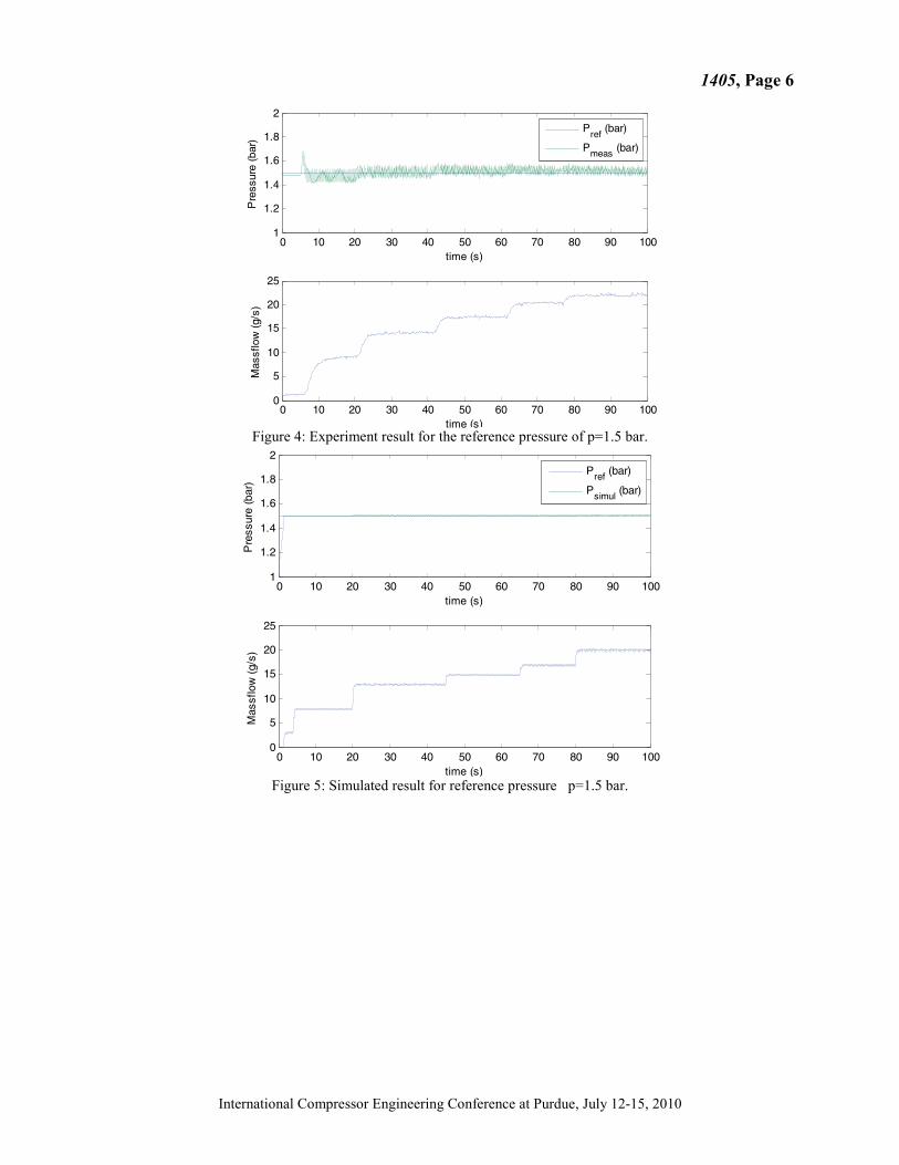
4.3 Simulation and experimental results Figure 4, Figure 5, Figure 6, Figure 7 show the comparison between the experiments and simulated results for different pressure references when the mass flow varies around 3 g/s to 20 g/s. It can be seen that the PI control based on Zeigler Nichols method is satisfactory in both cases. It can be conclude that the control strategy is working both in simulation and experimentation for different pressure references.
1405, Page 6
International Compressor Engineering Conference at Purdue, July 12-15, 2010
Figure 4: Experiment result for the reference pressure of p=1.5 bar.
Figure 5: Simulated result for reference pressure p=1.5 bar.
0 10 20 30 40 50 60 70 80 90 1001
1.2
1.4
1.6
1.8
2
time (s)P
ress
ure
(bar
)
0 10 20 30 40 50 60 70 80 90 1000
5
10
15
20
25
time (s)
Mas
sflo
w (
g/s)
Pref
(bar)
Pmeas (bar)
0 10 20 30 40 50 60 70 80 90 1001
1.2
1.4
1.6
1.8
2
time (s)
Pre
ssur
e (b
ar)
Pref (bar)
Psimul (bar)
0 10 20 30 40 50 60 70 80 90 1000
5
10
15
20
25
time (s)
Mas
sflo
w (
g/s)

1405, Page 7
International Compressor Engineering Conference at Purdue, July 12-15, 2010
Figure 6: Experiment result for the reference pressure of p=1.6 bar.
Figure 7: Simulated result for the reference pressure of p=1.6 bar.
4. CONCLUSION
A variable pressure strategy is a promising tool to increase the system efficiency of fuel cell systems. Indeed, the air compressor presents the major source of power losses in fuel cell systems. Especially in the low power output region the effect on the system efficiency is significant. However, a variable pressure strategy requires a fast and accurate control of mass flow and pressure. Two independent control loops with PI controller based on Zeigler Nichols method are used to control the mass flow and the pressure. The simulated and experimental results show a good agreement and show the goodness of the chosen control strategy.
0 10 20 30 40 50 60 70 80 90 1001
1.2
1.4
1.6
1.8
2
time (s)
Pre
ssur
e (b
ar)
0 10 20 30 40 50 60 70 80 90 100-10
0
10
20
30
time (s)
Mas
sflo
w (
g/s)
Pref (bar)
Pmeas (bar)
0 10 20 30 40 50 60 70 80 90 1001
1.2
1.4
1.6
1.8
2
time (s)
Pre
ssur
e (b
ar)
Pref (bar)
Psimul (bar)
0 10 20 30 40 50 60 70 80 90 1000
5
10
15
20
25
time (s)
Mas
sflo
w (
g/s)

1405, Page 8
International Compressor Engineering Conference at Purdue, July 12-15, 2010
REFERENCES
ASTRÖM K.J. and HÄGGLUND T. Automatic tuning of simple regulators with specifications on phase and amplitude margins [Journal]. - [s.l.] : Automatica, 1984. - Vol. Automatica. Blunier Benjamin and Miraoui Abdellatif Proton Exchange Membrane Fuel Cell Air Management in Automotive Applications [Journal] // Journal of Fuel Cell Science and Technology . - 2010. - pp. Volume 7, (11 pages) . DESHPANDE P.B. and ASH R.H. Computer process control [Journal]. - [s.l.] : ISA Pub, 1981. M'BOUA jeremie and Benjamin Blunier Abdelatif Miraoui A new analytical model of a three-lobes compressor, geometrical model, thermal model, simulation and experimental validation [Journal]. - [s.l.] : International Journal of refrigeration, 2010. - Vol. submitted. M'BOUA jeremie, Benjamin Blunier and Abdelatif Miraoui Geometrical and Thermodynamic Model of a Three Lobes Compressor with Simulation and Experimental Validation [Conference] // International Compressor Engineering Conference at Purdue, July 12-15, 2010. - Purdue : [s.n.], 2010. - Vol. Submitted. Qureshi TQ and Tassou SA Investigation into alternative compressor technologies for variable speed refrigeration applications [Conference] // International Compressor Technology Conference. - Purdue : [s.n.], 1994. Swan David H [et al.] Fuel cell dynamics in transit Application [Conference] // Proceedings of the 12th International Electric Vehicle . - Anaheim, California : [s.n.], 1994. - Vol. I.