Embed Size (px)
Citation preview

User’sManual Model ZR202G
Integrated type Zirconia Oxygen/Humidity Analyzer
IM 11M12A01-04E
IM 11M12A01-04E11th Edition

i
IM 11M12A01-04E 11th Edition : Jul. 19, 2017-00
u IntroductionThank you for purchasing the ZR202G Integrated type Oxygen/Humidity Analyzer.Please read the following respective documents before installing and using the ZR202G Integrated type Oxygen/Humidity Analyzer.
The related documents are as follows.
General SpecificationsContents Document number Note
Model ZR22G, ZR402G, and ZR202GDirect In Situ Zirconia Oxygen Analyzers and High Temperature Humidity Analyzers
GS 11M12A01-01E
* the “E” in the document number is the language code.
User’s ManualContents Document number Note
Model ZR202GIntegrated type Oxygen/Humidity Analyzer IM 11M12A01-04E (This manual)
Model ZR22A, ZR202AHeater Assembly IM 11M12A01-21E
Model EXAxt ZR SeriesHART Protocol IM 11M12A01-51E
* the “E” in the document number is the language code.
An exclusive User’s Manual might be attached to the products whose suffix codes or option codes contain the code “Z” (made to customers’ specifications). Please read it along with this manual.
The EXAxt ZR Integrated type Zirconia Oxygen/Humidity Analyzer is usually the Oxygen Analyzer, but it is to the High Temperature Humidity Analyzer when the option code “/HS (Set for Humidity Analyzer)” is selected.In this manual, the Oxygen Analyzer is mainly listed. When there are not mentions such as “in the case of Humidity Analyzer”, it becomes same as the Oxygen Analyzer.
The EXAxt ZR Integrated type Zirconia Oxygen/Humidity Analyzer has been developed for combustion control in various industrial processes. There are several version of this analyzer so you can select one that matches your application.Optional accessories are also available to improve measurement accuracy and automate calibration. An optimal control system can be realized by adding appropriate options.This instruction manual describes almost all of the equipment related to the EXAxt ZR. You may skip any section(s) regarding equipment which is not included in your system.Regarding the HART Communication Protocol, refer to IM 11M12A01-51E.IM 11M12A01-51E has been published as ‘’Model EXAxt ZR series HART protocol’’.Regarding Separate type Zirconia Oxygen Analyzer, refer to IM 11M12A01-02E.<Before using the equipment, please read any descriptions in this manual related to the equipment and system that you have, on appropriate use and operation of the EXAxt ZR.>
No. IM 11M12A01-04E 11th Edition : Jul. 2017 (YK)All Rights Reserved Copyright © 2000, Yokogawa Electric Corporation

ii
IM 11M12A01-04E 11th Edition : Jul. 19, 2017-00
Models and descriptions in this manual are listed below.
Models and descriptions in this manual
Model Product Name Description in this manualSpecification Installation Operation Maintenance CMPL
ZR202G Integrated type Oxygen Analyzer
ZO21R Probe protector
ZH21B Dust protector (only for Humidity analyzer)
ZA8F Flow setting unit (for manual calibration use)
ZR20H Automatic Calibration unit
- Case Assembly for calibration gas cylinder (Part No. E7044KF)
- Check valve (Part No. K9292DN, K9292DS)
- Dust filter for the detector (Part No. K9471UA)
- Dust guard protector (Part No. K9471UC)
ZO21S Standard gas unit CMPL: Customer Maintenance Parts List
This manual consists of twelve chapters. Please refer to the reference chapters for installation, operation and maintenance.
Table of Contents
Chapter Outline Relates toInstallation Operation Maintenance
1. Overview Equipment models and system configuration examples B C B
2. SpecificationsStandard specification, model code (or part number), dimension drawing for each equipment
A B B
3. Installation Installation method for each equipment A C
4. Piping Examples of piping in three standard system configurations A C
5. Wiring Wiring procedures such as “Power supply wiring”, “output signal wiring” or others A C
6. Components Major parts and function are described in this manual C B B
7. StartupBasic procedure to start operation of EXAxt ZR. Chapter 7 enables you to operate the equipment immediately.
A C
8. Detailed Data Setting Details of key operations and displays B C
9. Calibration Describes the calibration procedure required in the course of operation. B C
10. Other Functions Other functions described B C
11. Inspection and Maintenance
How to conduct maintenance of EXAxt ZR and procedures for replacement of deteriorated parts
B A
12. Troubleshooting This chapter describes measures to be taken when an abnormal condition occurs. C A
CMPL (parts list) User replaceable parts list C BA: Read and completely understand before operating the equipment.B: Read before operating the equipment, and refer to it whenever necessary.C: Recommended to read it at least once.
iii
IM 11M12A01-04E 11th Edition : Jul. 19, 2017-00
n For the safe use of this equipment
WARNINGBe sure not to accidentally drop it. Handle safely to avoid injury.Connect the power supply cord only after confirming that the supply voltage matches the rating of this equipment. In addition, confirm that the power is switched off when connecting power supply.Some sample gas is dangerous to people. When removing this equipment from the process line for maintenance or other reasons, protect yourself from potential poisoning by using a protective mask or ventilating the area well.
CAUTIONThe cell (sensor) at the tip of the probe is made of ceramic (zirconia element). Do not drop the equipment or subject it to pressure stress.
• Do NOT allow the sensor (probe tip) to make contact with anything when installing the analyzer.
• Avoid any water dropping directly on the probe (sensor) of the analyzer when installing it.• Check the calibration gas piping before introducing the calibration gas to ensure that there
is no leakage of the gas. If there is any leakage of the gas, the moisture drawn from the sample gas may damage the sensor.
• The probe (especially at the tip) becomes very hot. Be sure to handle it with gloves.
n NOTICE
l Specification check When the instrument arrives, unpack the package with care and check that the instrument
has not been damaged during transportation. In addition, please check that the specification matches the order, and required accessories are not missing. Specifications can be checked by the model codes on the nameplate. Refer to Chapter 2 Specifications for the list of model codes.
l Details on operation parameters When the EXAxt ZR Separate type Oxygen Analyzer arrives at the user site, it will operate
based on the operation parameters (initial data) set before shipping from the factory. Ensure that the initial data is suitable for the operation conditions before conducting analysis. Where necessary, set the instrument parameters for appropriate operation. For details of setting data, refer to chapters 7 to 10. When user changes the operation parameter, it is recommended to note down the changed setting data.
iv
IM 11M12A01-04E 11th Edition : Jul. 19, 2017-00
u Safety Precautionsn Safety, Protection, and Modification of the Product
• In order to protect the system controlled by the product and the product itself and ensure safe operation, observe the safety precautions described in this user’s manual. We assume no liability for safety if users fail to observe these instructions when operating the product.
• If this instrument is used in a manner not specified in this user’s manual, the protection provided by this instrument may be impaired.
• If any protection or safety circuit is required for the system controlled by the product or for the product itself, prepare it separately.
• Be sure to use the spare parts approved by Yokogawa Electric Corporation (hereafter simply referred to as YOKOGAWA) when replacing parts or consumables.
• Modification of the product is strictly prohibited.• The following safety symbols are used on the product as well as in this manual.
WARNINGThis symbol indicates that an operator must follow the instructions laid out in this manual in order to avoid the risks, for the human body, of injury, electric shock, or fatalities. The manual describes what special care the operator must take to avoid such risks.
CAUTIONThis symbol indicates that the operator must refer to the instructions in this manual in order to prevent the instrument (hardware) or software from being damaged, or a system failure from occurring.
CAUTIONThis symbol gives information essential for understanding the operations and functions.
NOTEThis symbol indicates information that complements the present topic.
This symbol indicates Protective Ground Terminal.
This symbol indicates Function Ground Terminal. Do not use this terminal as the protective ground terminal.
n Warning and DisclaimerThe product is provided on an “as is” basis. YOKOGAWA shall have neither liability nor responsibility to any person or entity with respect to any direct or indirect loss or damage arising from using the product or any defect of the product that YOKOGAWA can not predict in advance.
v
IM 11M12A01-04E 11th Edition : Jul. 19, 2017-00
n Notes on Handling User’s Manuals• Please hand over the user’s manuals to your end users so that they can keep the user’s
manuals on hand for convenient reference.• Please read the information thoroughly before using the product.• The purpose of these user’s manuals is not to warrant that the product is well suited to any
particular purpose but rather to describe the functional details of the product.• No part of the user’s manuals may be transferred or reproduced without prior written
consent from YOKOGAWA.• YOKOGAWA reserves the right to make improvements in the user’s manuals and product at
any time, without notice or obligation.• If you have any questions, or you find mistakes or omissions in the user’s manuals, please
contact our sales representative or your local distributor.
n Drawing ConventionsSome drawings may be partially emphasized, simplified, or omitted, for the convenience of description.Some screen images depicted in the user’s manual may have different display positions or character types (e.g., the upper / lower case). Also note that some of the images contained in this user’s manual are display examples.In the figure listed in this manual, the example of the oxygen analyzer is shown mainly. In the case of the humidity analyzer, unit indication may be different. Please read it appropriately.
n Product DisposalThe instrument should be disposed of in accordance with local and national legislation/regulations.
n Trademark Acknowledgments• All other company and product names mentioned in this user’s manual are trademarks or
registered trademarks of their respective companies.• We do not use TM or ® mark to indicate those trademarks or registered trademarks in this
user’s manual.

vi
IM 11M12A01-04E 11th Edition : Jul. 19, 2017-00
n Special descriptions in this manualThis manual indicates operation keys, displays and drawings on the product as follows:
l Operation keys, displays on the panelEnclosed in [ ]. (Ex. “MODE” key)(Ex. message display → “BASE”)(Ex. data display → “102” lit, “102” flashing)
l Drawing for flashingIndicated by gray characters (Flashing) (lit)
l Displays on the LCD display panel
9
8
7
6
5
4
3
2
1
0
W
V
U
T
S
R
Q
P
O
N
M
L
K
J
I
H
G
F
E
D
C
B
A
Alphanumerics Alphanumerics AlphanumericsLED Display LED Display LED Display
Z
Y

vii
IM 11M12A01-04E 11th Edition : Jul. 19, 2017-00
u CE marking productsn Authorised Representative in EEA
The Authorised Representative for this product in EEA is Yokogawa Europe B.V. (Euroweg 2, 3825 HD Amersfoort, The Netherlands).
n Identification TagThis manual and the identification tag attached on packing box are essential parts of the product.Keep them together in a safe place for future reference.
n UsersThis product is designed to be used by a person with specialized knowledge.
n How to dispose the batteries:This is an explanation about the EU Battery Directive. This directive is only valid in the EU.Batteries are included in this product. Batteries incorporated into this product cannot be removed by yourself. Dispose them together with this product.When you dispose this product in the EU, contact your local Yokogawa Europe B.V.office. Do not dispose them as domestic household waste.
Battery type: Manganese dioxide lithium battery
Notice: The symbol (see above) means they shall be sorted out and collected as ordained in the EU Battery Directive.

Blank Page

Toc-1
IM 11M12A01-04E 11th Edition : Jul. 19, 2017-00
Model ZR202GIntegrated typeOxygen/Humidity Analyzer
CONTENTS
IM 11M12A01-04E 11th Edition
u Introduction ....................................................................................................iu Safety Precautions ......................................................................................ivu CE marking products .................................................................................vii1. Overview .................................................................................................... 1-1
1.1 < EXAxt ZR > System Configuration ............................................................... 1-11.1.1 System 1 ............................................................................................1-1
1.1.2 System 2 ............................................................................................1-2
1.1.3 System 3 ............................................................................................1-3
1.2 < EXAxt ZR > System Components ................................................................1-41.2.1 System Components ......................................................................... 1-4
1.2.2 Oxygen/Humidity Analyzer and Accessories ..................................... 1-4
2. Specifications ........................................................................................... 2-12.1 General Specifications .....................................................................................2-1
2.1.1 Standard Specifications ..................................................................... 2-1
2.1.2 ZR202G Integrated type Zirconia Oxygen Analyzer .......................... 2-2
2.1.3 ZO21R Probe Protector .....................................................................2-9
2.1.4 ZH21B Dust Protector ......................................................................2-10
2.2 ZA8F Flow Setting Unit and ZR20H Automatic Calibration Unit ................ 2-112.2.1 ZA8F Flow Setting Unit .................................................................... 2-11
2.2.2 ZR20H Automatic Calibration Unit ...................................................2-14
2.3 ZO21S Standard Gas Unit ..............................................................................2-162.4 Other Equipment .............................................................................................2-17
2.4.1 Dust Filter for Oxygen Analyzer (part no. K9471UA) .......................2-17
2.4.2 Dust Guard Protector (K9471UC) ....................................................2-17
2.4.3 Stop Valve (part no. L9852CB or G7016XH) ...................................2-18
2.4.4 Check Valve (part no. K9292DN or K9292DS) ................................2-18
2.4.5 Air Set ...............................................................................................2-19
2.4.6 Zero Gas Cylinder (part no. G7001ZC) ...........................................2-20
2.4.7 Pressure Regulator (G7013XF or G7014XF) for Gas Cylinder .......2-21
2.4.8 Case Assembly (E7044KF) for Calibration gas Cylinder .................2-21
2.4.9 ZR202A Heater Assembly ...............................................................2-22
3. Installation ................................................................................................. 3-13.1 Installation of ZR202G Zirconia Oxygen/Humidity Analyzer ....................... 3-1

Toc-2
IM 11M12A01-04E 11th Edition : Jul. 19, 2017-00
3.1.1 Probe Insertion Hole .......................................................................... 3-1
3.1.2 Installation of the Probe .....................................................................3-2
3.1.3 Installation of the Dust Filter (K9471UA), Dust Guard Protector (K9471UC) Probe Protector (ZO21R) ............................................... 3-2
3.1.4 Installation of ZH21B Dust Protector ................................................. 3-4
3.2 Installation of ZA8F Flow Setting Unit ............................................................ 3-53.3 Installation of ZR20H Automatic Calibration Unit ......................................... 3-63.4 Installation of the Case Assembly (E7044KF) for Calibration Gas Cylinder 3-73.5 Insulation Resistance Test ............................................................................... 3-8
4. Piping ......................................................................................................... 4-14.1 Piping for System 1 ...........................................................................................4-1
4.1.1 Piping Parts for System 1 .................................................................. 4-2
4.1.2 Piping for the Calibration Gas ............................................................4-2
4.1.3 Piping for the Reference Gas.............................................................4-2
4.2 Piping for System 2 ...........................................................................................4-24.2.1 Piping Parts for System 2 .................................................................. 4-3
4.2.2 Piping for the Calibration Gas ............................................................4-3
4.2.3 Piping for the Reference Gas.............................................................4-4
4.3 Piping for System 3 ...........................................................................................4-44.4 Piping for the Oxygen Analyzer with Pressure Compensation ................... 4-6
4.4.1 Piping Parts for Oxygen Analyzer with Pressure Compensation ...... 4-8
4.4.2 Piping for the Calibration Gas ............................................................4-8
4.4.3 Piping for the Reference Gas.............................................................4-8
5. Wiring ......................................................................................................... 5-15.1 General ...............................................................................................................5-1
5.1.1 Terminals for the External Wiring ....................................................... 5-2
5.1.2 Wiring .................................................................................................5-2
5.1.3 Mounting of Cable Gland ................................................................... 5-3
5.2 Wiring for Analog Output .................................................................................5-35.2.1 Cable Specifications .......................................................................... 5-4
5.2.2 Wiring Procedure ............................................................................... 5-4
5.3 Wiring Power and Ground Terminals ............................................................. 5-45.3.1 Wiring for Power Line ......................................................................... 5-4
5.3.2 Wiring for Ground Terminals ..............................................................5-5
5.4 Wiring for Contact Output ................................................................................5-55.4.1 Cable Specifications .......................................................................... 5-5
5.4.2 Wiring Procedure ............................................................................... 5-5
5.5 Wiring for Contact Input ...................................................................................5-55.5.1 Cable Specifications .......................................................................... 5-6
5.5.2 Wiring Procedure ............................................................................... 5-6
6. Components ............................................................................................. 6-16.1 ZR202G Zirconia Oxygen/Humisity Analyzer ................................................ 6-1
Toc-3
IM 11M12A01-04E 11th Edition : Jul. 19, 2017-00
6.2 ZA8F Flow Setting Unit, ZR20H Automatic Calibration Unit ........................ 6-2
7. Startup ....................................................................................................... 7-17.1 Checking Piping and Wiring Connections ..................................................... 7-17.2 Valve Setup ........................................................................................................7-17.3 Supplying Power to Converter ........................................................................7-27.4 Operation of Infrared Switch ........................................................................... 7-2
7.4.1 Display and Switches ......................................................................... 7-2
7.4.2 Display Configuration ......................................................................... 7-4
7.4.3 Entering Parameter Code Selection Display ..................................... 7-5
7.4.4 Selecting Parameter Codes ............................................................... 7-6
7.4.5 Changing Set Values ......................................................................... 7-6
7.5 Confirmation of Equipment Type Setting .......................................................7-87.6 Selection of Measurement Gas .......................................................................7-97.7 Output Range Setting .......................................................................................7-9
7.7.1 Oxygen Analyzer -Minimum Current (4 mA) and Maximum Current (20 mA) Settings.......................................................................................7-9
7.7.2 Output Range Setting ...................................................................... 7-11
7.7.3 Humidity Analyzer -Minimum Current (4 mA) and Maximum Current (20 mA) Settings..................................................................................... 7-11
7.8 Setting Display Item ........................................................................................7-127.8.1 Oxygen Analyzer - Setting Display Item ..........................................7-12
7.8.2 Humidity Analyzer - Setting Display Item .........................................7-13
7.9 Checking Current Loop ..................................................................................7-137.10 Checking Contact I/O ......................................................................................7-14
7.10.1 Contact Output Check .....................................................................7-14
7.10.2 Checking Calibration Contact Output ..............................................7-15
7.10.3 Checking Input Contacts ..................................................................7-16
7.11 Calibration .......................................................................................................7-167.11.1 Calibration Setup .............................................................................7-16
7.11.2 Manual Calibration ...........................................................................7-19
8. Detailed Data Setting ............................................................................... 8-18.1 Current Output Setting .....................................................................................8-1
8.1.1 Oxygen Analyzer_Current Output Setting ......................................... 8-1
8.1.2 Oxygen Analyzer_Analog Output Setting .......................................... 8-1
8.1.3 Setting Minimum Oxygen Concentration (at 4 mA) and Maximum Oxygen Concentration (at 20 mA) ...................................................................8-2
8.1.4 Minimum and Maximum Settings Corresponding to 4 mA and 20 mA 8-2
8.1.5 Input Ranges ......................................................................................8-2
8.1.6 Entering Output Damping Constants ................................................. 8-5
8.1.7 Selection of Output Mode ..................................................................8-5
8.1.8 Default Values .................................................................................... 8-5
8.2 Output Hold Setting ..........................................................................................8-58.2.1 Definition of Equipment Status .......................................................... 8-6
Toc-4
IM 11M12A01-04E 11th Edition : Jul. 19, 2017-00
8.2.2 Preference Order of Output Hold Value ............................................. 8-7
8.2.3 Output Hold Setting ............................................................................ 8-7
8.2.4 Default Values .................................................................................... 8-7
8.3 Setting Alarms ...................................................................................................8-88.3.1 Alarm Values ......................................................................................8-8
8.3.2 Alarm Output Actions ......................................................................... 8-8
8.3.3 Alarm Setting......................................................................................8-9
8.3.4 Default Values ..................................................................................8-10
8.4 Output Contact Setup .....................................................................................8-108.4.1 Output Contact .................................................................................8-10
8.4.2 Setting Output Contact .................................................................... 8-11
8.4.3 Default Values ..................................................................................8-12
8.5 Input Contact Settings ....................................................................................8-128.5.1 Input Contact Functions ...................................................................8-12
8.5.2 Setting Input Contact .......................................................................8-13
8.5.3 Default Values ..................................................................................8-13
8.6 Other Settings .................................................................................................8-138.6.1 Setting the Date-and-Time ...............................................................8-13
8.6.2 Setting Periods over which Average Values are Calculated and Periods over which Maximum and Minimum Values Are Monitored.............8-14
8.6.3 Setting Fuels ....................................................................................8-15
8.6.4 Setting Measurement Gas Temperature and Pressure ...................8-19
8.6.5 Setting Purging ................................................................................8-20
9. Calibration ................................................................................................. 9-19.1 Calibration Briefs ..............................................................................................9-1
9.1.1 Principle of Measurement with a zirconia oxygen analyzer .............. 9-1
9.1.2 Measurement Principle of Zirconia Humidity Analyzer ...................... 9-2
9.1.3 Calibration Gas ..................................................................................9-4
9.1.4 Compensation .................................................................................... 9-4
9.1.5 Characteristic Data from a Sensor Measured During Calibration ..... 9-5
9.2 Calibration Procedures ....................................................................................9-69.2.1 Mode ..................................................................................................9-6
9.2.2 Calibration Procedure ........................................................................9-6
9.2.3 Zero gas Concentration ..................................................................... 9-7
9.2.4 Span gas Concentration .................................................................... 9-7
9.2.5 Calibration Time ................................................................................. 9-7
9.3 Calibration .........................................................................................................9-99.3.1 Manual Calibration ............................................................................. 9-9
9.3.2 Semi-automatic Calibration ...............................................................9-9
9.3.3 Automatic Calibration .......................................................................9-10
10. Other Functions ...................................................................................... 10-110.1 Detailed Display ..............................................................................................10-1

Toc-5
IM 11M12A01-04E 11th Edition : Jul. 19, 2017-00
10.1.1 Oxygen Concentration .....................................................................10-2
10.1.2 Humidity ...........................................................................................10-2
10.1.3 Mixing Ratio .....................................................................................10-2
10.1.4 Relative Humidity .............................................................................10-2
10.1.5 Dew Point .........................................................................................10-2
10.1.6 Air Ratio............................................................................................10-3
10.1.7 Cell Temperature ..............................................................................10-3
10.1.8 Process Gas Temperature ...............................................................10-3
10.1.9 C. J. Temperature.............................................................................10-3
10.1.10 Amount of Water Vapor in Exhaust Gas ..........................................10-3
10.1.11 Cell Voltage ......................................................................................10-4
10.1.12 Thermocouple Voltage .....................................................................10-4
10.1.13 Cold Junction Voltage ......................................................................10-4
10.1.14 Current Output .................................................................................10-4
10.1.15 Response Time ................................................................................10-4
10.1.16 Cell’s Internal Resistance ................................................................10-5
10.1.17 Robustness of a Cell ........................................................................10-5
10.1.18 Heater On-Time Ratio ......................................................................10-5
10.1.19 Oxygen Concentration (with time constant), Humidity (with time constant), and Mixing Ratio (with time constant) .............................................................10-6
10.1.20 Maximum Oxygen Concentration, Humidity, and Mixing Ratio ......10-6
10.1.21 Minimum Oxygen Concentration, Humidity, and Mixing Ratio ........10-6
10.1.22 Average Oxygen Concentration, Humidity, and Mixing Ratio .........10-6
10.1.23 Span and Zero Correction Ratios ....................................................10-6
10.1.24 History of Calibration Time ...............................................................10-7
10.1.25 Time .................................................................................................10-7
10.1.26 Software Revision ............................................................................10-7
10.2 Operational Data Initialization ......................................................................10-710.3 Initialization Procedure ..................................................................................10-810.4 Reset .................................................................................................................10-810.5 Handling of the ZO21S Standard Gas Unit .................................................10-21
10.5.1 Standard Gas Unit Component Identification ................................10-21
10.5.2 Installing Gas Cylinders .................................................................10-21
10.5.3 Calibration Gas Flow ......................................................................10-22
10.6 Methods of Operating Valves in the ZA8F Flow Setting Unit ...................10-2310.6.1 Preparation Before Calibration ......................................................10-24
10.6.2 Operating the Span Gas Flow Setting Valve .................................10-24
10.6.3 Operating the Zero Gas Flow Setting Valve ..................................10-24
10.6.4 Treatment After Calibration ............................................................10-24
11. Inspection and Maintenance ................................................................. 11-111.1 Inspection and Maintenance of the Detector ............................................... 11-1
11.1.1 Cleaning the Calibration Gas Tube .................................................. 11-1

Toc-6
IM 11M12A01-04E 11th Edition : Jul. 19, 2017-00
11.1.2 Replacing the Sensor Assembly ...................................................... 11-2
11.1.3 Replacement of the Heater Assembly ............................................. 11-4
11.1.4 Replacement of Dust Filter .............................................................. 11-6
11.1.5 Replacement of O-ring ..................................................................... 11-6
11.1.6 Stopping and Re-starting Operation ................................................ 11-7
11.2 Inspection and Maintenance of the Converter ............................................ 11-711.3 Replacement of Flowmeter for ZR20H Automatic Calibration Unit .......... 11-9
12. Troubleshooting ..................................................................................... 12-112.1 Displays and Measures to Take When Errors Occur ..................................12-1
12.1.1 What is an Error? .............................................................................12-1
12.1.2 Measures to Take When an Error Occurs .......................................12-2
12.2 Displays and Measures to Take When Alarms are Generated ...................12-412.2.1 What is an Alarm? ............................................................................12-4
12.2.2 Measures Taken When Alarms are Generated ...............................12-4
12.3 Measures When Measured Value Shows an Error ......................................12-812.3.1 Measured Value Higher (Lower for Humidity Analyzer) Than True Value ..12-8
12.3.2 Measured Value Lower (Higher for Humidity Analyzer) Than True Value ..12-9
12.3.3 Measurements Sometimes Show Abnormal Values .....................12-10
Customer Maintenance Parts List ......................................CMPL 11M12A01-04ECustomer Maintenance Parts List ......................................CMPL 11M12A01-12ECustomer Maintenance Parts List ..........................................CMPL 11M3D1-01ERevision Information ...............................................................................................i

<1. Overview> 1-1
IM 11M12A01-04E 11th Edition : Jul. 19, 2017-00
1. OverviewThe EXAxt ZR Integrated type Zirconia Oxygen/Humidity Analyzer is used to monitor and control the oxygen concentration in combustion gases, in boilers and industrial furnaces, for wide application in industries which consume considerable energy-such as steel, electric power, oil and petrochemical, ceramics, pulp and paper, food, or textiles, as well as incinerators and medium/small boilers. It can help conserve energy in these industries. The EXAxt ZR also contributes to preservation of the earth’s environment in preventing global warming and air pollution by controlling complete combustion to reduce CO2, SOx and NOx.The EXAxt ZR Integrated type Zirconia Oxygen/Humidity Analyzer integrates both probe and converter. The analyzers need not use a sampling device, and allow direct installation of the probe in the wall of a flue or furnace to measure the concentration of oxygen in the stack gas of the temperature up to 700°C.The EXAxt ZR Integrated-type Zirconia High-temperature Humidity Analyzer integrates the detector and the converter in one unit. This analyzer can measure humidity of hot air continuously, so can be used to measure humidity of air in driers which are heated by steam or electricity. It can also be used in a variety of manufacturing applications with humidifiers, as well as with driers, for humidity measurement and control. It can help improve productivity in these application fields.The probe uses a high-reliability Zirconia sensor and a heater assembly that can be replaced on site.The analyzer is equipped with three infrared switches, which enable the user to operate the equipment without opening the cover on site. Analyzer calibration can also be fully automated and the automatic calibration unit is provided. Choose the equipment which best suits your needs so that an optimal combustion control system can be obtained.Some examples of typical system configuration are illustrated below:
1.1 < EXAxt ZR > System ConfigurationThe system configuration should be determined by the conditions; e.g. whether the calibration is to be automated, and whether flammable gas is present and requires safety precautions. The system configuration can be classified into three basic patterns as follows:
1.1.1 System 1This is the simplest system consisting of an integrated type analyzer. This system can be implemented for monitoring oxygen concentration in the combustion gases boiler, and can be implemented for monitoring humidity in a production process such as food production.No piping is required for the reference gas (air) which is fed in at the installation site. The ZO21S standard gas unit is used for calibration.Zero gas from this unit and span gas (air) is sent to the probe through a tube which is connected during calibration.

<1. Overview> 1-2
IM 11M12A01-04E 11th Edition : Jul. 19, 2017-00
~
ZR202G Integrated type Zirconia Oxygen/Humidity Analyzer
ZO21S Standard gas unit
Stop valve
Calibration gas
F1.1E.ai
~
100 to 240 V AC
100/110/115200/220/240 V AC
Contact inputAnalog output, contact outputDigital output (HART)
Figure1.1 Example of System 1
NOTE• As this system uses ambient air for the reference gas, measuring accuracy will be affected
by the installation location.• A stop valve should be connected to the calibration gas inlet of the equipment. The valve
should be fully closed unless calibration is in progress.
1.1.2 System 2This system is for monitoring and controlling oxygen concentration in the combustion gases of a large-size boiler or heating furnace. Instrument air (clean and dry air of oxygen concentration 21%) is used as the reference gas and the span gas for calibration. Zero gas is fed from a cylinder during calibration. In case of humidity analyzer, this system is for accurate monitoring and controlling humidity when the installation environment is polluted with gases other than the air. Instrument air (clean and dry air of oxygen concentration 21%) is used for the reference gas and the span gas for calibration.The gas flow is controlled by the ZA8F flow setting unit (for manual valve operation).
~
ZR202G Integrated type Zirconia Oxygen/Humidity Analyzer
F1.2E.ai
ZA8F flow setting unit
Reference gas
Calibration gas
Needle valveFlowmeter
Instrument air
Air Set
Calibration gas pressure
regulatorZero gas cylinder
Calibration gas unit case
Stop valveor
Check valve
Span gas(Same as Zero gas calibration)
100 to 240 V ACContact inputAnalog output, contact outputDigital output (HART)
Figure1.2 Example of System 2

<1. Overview> 1-3
IM 11M12A01-04E 11th Edition : Jul. 19, 2017-00
1.1.3 System 3This example, System 3, represents typical applications in large boilers and heating furnaces, where is a need to monitor and control oxygen concentration. The reference gas and calibration-time span gas are (clean, dry) instrument air. Zero gas is supplied from a gas cylinder.System 3 uses the ZR20H automatic calibration unit, with auto-switching of the calibration gas.A “combustible gas detected” contact input turns off power to the heater. There’s also contact output from the converter that can be used to operate a purge gas valve to supply air to the sensor.
~ 100 to 240 V ACAutomatic calibration unit
Reference gas
Calibration gas (Zero)
Contact inputAnalog output, contact outputDigital output (HART)
Air Set
Instrument air
Calibration gas unit case
Calibration gas pressure
regulator Zero gas cylinder
ZR202G Integrated type Zirconia Oxygen/Humidity Analyzerwith automatic calibration unit (ZR202G----A-----A)
F1.3E.ai
Span gas
ZR20H
*3
Note: The installation temperature limits range for integrated type analyzer is -20 to 55°C.
*2
*1
*1 Shield cable: Use shielded signal cables, and connect the shields to the FG terminal of the converter.
*2 Select the desired probe from the Probe Configuration table on page 1-4. *3 When a zirconia oxygen analyzer is used, 100% N2 gas cannot be used as the zero gas.
Use approx. 1 vol% O2 gas (N2-based).Figure1.3 Example of System 3

<1. Overview> 1-4
IM 11M12A01-04E 11th Edition : Jul. 19, 2017-00
1.2 < EXAxt ZR > System Components1.2.1 System Components
System ComponentsSeparate type
Oxygen Analyzer
Humidity AnalyzerSystem config.
Ex.1 Ex.2 Ex.3Model ZR202G Integrated type Zirconia Oxygen Analyzers A A A A AModel ZO21R Probe Protector for Zirconia Oxygen Analyzers B B B BK9471UA Dust Filter for Oxygen Analyzer B B B BK9471UC Dust Guard Protector B B B B BZH21B Dust protector (only for Humidity Analyzer) B B B BModel ZO21S Standard Gas Unit A B BModel ZA8F Flow Setting Unit for manual calibration A B BModel ZR20H Automatic Calibration Unit for Integrated type Analyzer A B BL9852CB, G7016XH Stop Valve for Calibration gas line A (A) B BK9292DN,K9292DS Check Valve for Calibration gas line (A) B BG7003XF/K9473XK, G7004XF/K9473XG Air Set A A B BG7001ZC Zero gas Cylinder A A B BG7013XF, G7014XF Pressure Reducing Valve for Gas Cylinder A A B BE7044KF Case Assembly for Calibration gas Cylinder A A B BModel ZR202A Heater Assembly (Spare Parts for ZR202G) B B B B B
A: Items required for the above system exampleB: To be selected depending on each application. For details, refer to corresponding chapter.(A): Select either
1.2.2 Oxygen/Humidity Analyzer and Accessories
F1.4E.ai
Detector(ZR202G)
Detector(ZR202G)
Probe Protector(ZO21R)
Dust Filter(K9471UA)
orDust GuardProtector
(K9471UC)
+
Sample gas temperature 0 to 700°CMounting Insertion length General-use Probe Application
Horizontalto
vertical
Horizontalto
vertical
Horizontalto
vertical
Vertical
Vertical
0.4to
2 m
0.4 to2 m
2.5 mor more
3 m or less
2.5 m or more
• Boiler• Heating furnace
• For pulverized coal boiler with gas flow velocity 10 m/sec or more
• Cement Kiln
• Black liquid recovery boiler• Cement Kiln
Gas Flow
Sample inlet
Dust protector(ZH21B)
ZR202G
Only ZR22G-040
Humidity analyzer use
<2.Specifications> 2-1
IM 11M12A01-04E 11th Edition : Jul. 19, 2017-00
2. SpecificationsThis chapter describes the specifications for the following:ZR202G General-use Integrated type Zirconia Oxygen Analyzer (See Section 2.1.2)ZO21R-L Probe protector (See Section 2.1.3)ZH21B Dust protector (See Section 2.1.4)ZA8F Flow setting unit (See Section 2.2.1)ZR20H Automatic calibration unit (See Section 2.2.2)ZO21S Standard gas unit (See Section 2.3)K9471UA Dust Filter for Oxygen Analyzer (See Section 2.4)
2.1 General Specifications2.1.1 Standard Specifications
Measured Object: Oxygen concentration in combustion exhaust gas and mixed gas (excluding inflammable gases). May not be applicable corrosive gas such as ammonia, chlorine is present-check with YOKOGAWA.) (In case of Humidity Analyzer, Water vapor (in vol%) in mixed gases (air and water vapor))
Measured System: Zirconia systemMeasurement Range: 0.01 to 100 vol%O2 (In case of Humidity Analyzer, 0 to 100 vol% H2O or 0 to 1.000 kg/kg)Output Signal: 4 to 20 mA DC (maximum load resistance 550 Ω)Setting Range: Any setting in the range of 0 to 5 through 0 to 100 vol%O2 (in 1 vol%O2),
or partial range In case of Humidity Analyzer, Moisture quantity: 0 to 25 through 0 to 100 vol% H2O (in 1 vol% H2O), or
partial range. Mixture ratio; 0 to 0.2 through 0 to 1.000 kg/kg (in 0.001 kg/kg), or
partial range.Digital Communication (HART): 250 to 550 Ω, depending on number of field devices connected
to the loop (multi-drop mode). Note: HART is a registered trademark of the HART Communication Foundation.
Display Range: Oxygen concentration; 0 to 100 vol%O2 In case of Humidity Analyzer, Moisture quantity; 0 to 100 vol% H2O, Mixture ratio; 0 to 1 kg/kg, Relative humidity; 0 to 100% RH (Note), Dew point; -40 to 370°C (Note)
Note: These values are affected by temperature and absolute pressure, So accurate temperature and pressure values must be inputted to the converter.
Warm-up Time: Approx. 20 min.
These characteristics are calculated by oxygen concentration measured in air which include water vapor.Repeatability: (Excluding the case where the reference gas is by natural convection)
±0.5% Maximum value of set range; less than 0 to 25 vol%O2 range ±1% Maximum value of set range; 0 to 25 vol%O2 or more and up
to 0 to 100 vol%O2 range In case of Humidity Analyzer, ± 1 vol% H2O; (Sample gas pressure 2
kPa or less)
<2.Specifications> 2-2
IM 11M12A01-04E 11th Edition : Jul. 19, 2017-00
Linearity: (Excluding standard gas tolerance) (Excluding the case where the reference gas is by natural convection) (Use oxygen of known concentration (within the measuring range) as the zero and span calibration gases.)
±1% Maximum value of set range; less than 0 to 25 vol%O2 range
(Sample gas pressure: within ±4.9 kPa) ±3% Maximum value of set range; 0 to 25 vol%O2 or more and less than 0 to 50 vol%O2 range
(Sample gas pressure: within ±0.49 kPa) ±5% Maximum value of set range; 0 to 50 vol%O2 or more and up to 0 to 100 vol%O2 range
(Sample gas pressure: within ±0.49 kPa) In case of Humidity Analyzer,
± 2 vol% H2O; (Sample gas pressure: within ± 0.49 kPa) ± 3 vol% H2O; (Sample gas pressure: 2 kPa or less)
Drift: (Excluding the first two weeks in use) (Excluding the case where the reference gas is by natural convection.) Both zero and span ±2% Maximum value of set range/month
In case of Humidity Analyzer, Both zero and span ± 3 vol% H2O/month
Response Time: Response of 90% within 5 seconds. (Measured after gas is introduced from calibration gas inlet and analog output start changing.)
Installation Altitude: 2000 m or lessCategory based on IEC 61010: II (Note)Pollution degree based on IEC 61010: 2 (Note)Note: Installation category, called over-voltage category, specifies impulse withstand voltage. Category II is for electrical equipment. Pollution degree indicates the degree of existence of solid, liquid, gas or other inclusions which may reduce dielectric strength.
Degree 2 is the normal indoor environment.
Safety, EMC and RoHS conforming standards the ZR202GSafety: EN 61010-1, EN 61010-2-030, CAN/CSA-C22.2 No. 61010-1,
UL Std. No. 61010-1EMC: EN 61326-1 Class A*, Table 2, EN 61326-2-3, EN 61000-3-2 *: Influence of immunity environment (Criteria A ): ±20% of F. S. EMC Regulatory Arrangement in Australia and New Zealand (RCM)
EN61326-1 Class A Korea Electromagnetic Conformity Standard Note: This instrument is a Class A product, and it is designed for use in the industrial environment. Please use this
instrument in the industrial environment only.RoHS: EN 50581
2.1.2 ZR202G Integrated type Zirconia Oxygen AnalyzerCan be operated in the field without opening the cover using optical switches. Display: 6-digit LCDSwitch: Three optical switchesOutput Signal: 4 to 20 mA DC, one point (maximum load resistance 550 Ω)Digital Communication (HART): 250 to 550 Ω, depending on quantity of field devices connected
to the loop (multi-drop mode).Contact Output Signal: Two points (one is fail-safe, normally open)Contact Input Signal: Two points

<2.Specifications> 2-3
IM 11M12A01-04E 11th Edition : Jul. 19, 2017-00
Sample Gas Temperature: 0 to 700°C It is necessary to mount the cell using inconel cell-bolts when the temperature is greater than 600°C. High temperature service ― greater than 700°C ― is not available.
Sample Gas Pressure: -5 to +250 kPa (When the pressure in the furnace exceeds 3 kPa, it is recommended to use pressure compensated type. When the pressure in the furnace exceeds 5 kPa, pressure compensated type is required.) No pressure fluctuation in the furnace should be allowed.
Note: When the detector is used in conjunction with a check valve and the ZA8F Flow Setting Unit, the maximum pressure of sample gas is 150 kPa. When with a check valve and the ZR20H Automatic Calibration Unit, it is 200 kPa. If the pressure of your sample gas exceeds these limits, consult with Yokogawa.
Probe Length: 0.4, 0.7, 1.0, 1.5, 2.0, 2.5, 3.0 mProbe Material: SUS 316 (JIS)Ambient Temperature: -20 to +55°C (- 5 to +70°C on the case surface)Storage Temperature: -30 to +70°CHumidity Range: 0 to 95%RH (non-condensing)Power Supply Voltage: Ratings; 100 to 240 V AC Acceptable range; 85 to 264 V ACPower Supply Frequency: Ratings; 50/60 Hz Acceptable range; 45 to 66 HzPower Consumption: Max. 300 W, approx. 100 W for ordinary use.Reference Gas System: Natural Convection, Instrument Air, or Pressure CompensatedInstrument Air System (excluding Natural Convection): Pressure; 200 kPa + the pressure inside the furnace (It is recommended to use air
which is dehumidified by cooling to dew point -20°C or less, and dust or oil mist are removed.)
Consumption; Approx. 1Nl/minWetted Material: SUS 316 (JIS), Zirconia, SUS304 (JIS) or ASTM grade 304 (flange),
Hastelloy B, (Inconel 600, 601)Construction: Heater and thermocouple replaceable construction. Non explosion-proof JIS
C0920 / equivalent to IP44D. Equivalent to NEMA 4X/IP66 (Achieved when the cable entry is completely sealed with a cable gland in the recirculation pressure compensated version.)
Gas Connection: Rc1/4 or 1/4NPT(F)Wiring Connection: G1/2, Pg13.5, M20 x 1.5mm, 1/2NPT select one type (4 pieces)Installation: Flange mounting Probe Mounting Angle: Horizontal to vertically downward.
When the probe insertion length is 2 m or less, installing at angles from horizontal to vertically downward is available. When the probe insertion length is 2.5m or more, mount vertically downward (within ± 5°), and if installing at angles from horizontal to vertically downward (within ± 5°), use a probe protector.
Case: Aluminum alloyPaint Color: Cover; Mint green (Munsell 5.6BG3.3/2.9) Case; Mint green (Munsell 5.6BG3.3/2.9)Finish: Polyurethane corrosion-resistance coatingWeight: Insertion length of 0.4m: approx. 8 kg (JIS 5K 65) / approx. 13 kg (ANSI 150 4)
Insertion length of 1.0m: approx. 10 kg (JIS 5K 65) / approx. 15 kg (ANSI 150 4) Insertion length of 1.5m: approx. 12 kg (JIS 5K 65) / approx. 17 kg (ANSI 150 4) Insertion length of 2.0m: approx. 14 kg (JIS 5K 65) / approx. 19 kg (ANSI 150 4) Insertion length of 3.0m: approx. 17 kg (JIS 5K 65) / approx. 22 kg (ANSI 150 4)

<2.Specifications> 2-4
IM 11M12A01-04E 11th Edition : Jul. 19, 2017-00
Functions (inclused Humidity Analyzer)Display Function: Displays values of the measured oxygen concentration, moisture
quantity, mixture ratio, etc. Alarm, Error Display: Displays alarms such as “AL-06” or errors such as “Err-01” when any
such status occurs.Calibration Functions: Automatic calibration; Requires the Automatic Calibration Unit. It calibrates
automatically at specified intervals. Semi-auto Calibration; Requires the Automatic Calibration Unit. Input calibration start
signal by optical switch or contact, then it calibrates automatically afterwards.
Manual Calibration; Calibration with opening/closing the valve of calibration gas in operation interactively with the optical switch.
Maintenance Functions: Can operate updated data settings in daily operation and checking. Display data settings, calibration data settings, test settings (current output loop check, input/output contact check).
Setup Functions: Initial settings suit for the plant conditions when installing the converter. Current output data settings, alarm data settings, contact data settings, other settings.
Display and setting content:Display Related Items: Oxygen concentration (vol% O2), output current value (mA), air ratio,
moisture quantity (in hot gases) (vol% H2O), mixture ratio(kg/kg), relative humidity(%RH), dew point (°C), Cell temperature (°C ), thermocouple reference junction temperature (°C ), maximum/minimum/average oxygen concentration (vol% O2), maximum/ minimum/average moisture quantity (vol% H2O), maximum/minimum/average mixture ratio (kg/kg), cell e.m.f. (mV), cell internal resistance (Ω), cell condition (in four grades), heater on-time rate (%), calibration record (ten times), time (year/month/day/hour/minute), output 1, 2 current (mA), cell response time (seconds),
Calibration Setting Items: Span gas concentration (vol% O2), zero gas concentration (vol%O2), calibration mode (auto, semi-auto, manual), calibration type and method (zero-span calibration, zero calibration only, span calibration only), stabilization time (min.sec), calibration time (min.sec), calibration interval (day/hour), starting time (year/month/day/hour/minute)
Output Related Items: Analog output/output mode selection, output conditions when warming-up/maintenance/calibrating/abnormal, 4 mA/20 mA point oxygen concentration (vol% O2), time constant, preset values when warming-up/maintenance/calibrating/abnormal, output preset values on abnormal
Alarm Related Items: Oxygen concentration high alarm/high-high alarm limit values (vol% O2), oxygen concentration low alarm/low-low alarm limit values (vol% O2), oxygen concentration alarm hysteresis (vol% O2), moisture quantity high alarm/ high-high alarm limit values (vol% H2O), moisture quantity low alarm/ low-low alarm limit values (vol% H2O), mixture ratio high alarm/high-high alarm limit values (kg/kg), mixture ratio low alarm/ low-low alarm limit values (kg/kg), moisture quantity alarm hysteresis (vol% H2O), mixture ratio alarm hysteresis (kg/kg), oxygen concentration/moisture quantity/mixture ratio alarm detection,alarm delay (seconds)
Contact Related Items: Selection of contact input 1 and 2, selection of contact output 1 and 2 (abnormal, high-high alarm, high alarm, low alarm, low-low alarm, maintenance, calibrating, range switching, warming-up, calibration gas pressure decrease, flameout gas detection (answer-back of contact input)

<2.Specifications> 2-5
IM 11M12A01-04E 11th Edition : Jul. 19, 2017-00
Converter Output: One mA analog output point (4 to 20 mA DC (maximum load resistance of 550Ω)) with mA digital output point (HART) (minimum load resistance of 250Ω).
Oxygen analyzer; Range; Any setting between 0 to 5 through 0 to 100 vol% O2 in 1 vol% O2, and partial range is available (Maximum range value/minimum range value 1.3 or more) For the log output, the minimum range value is fixed at 0.1 vol% O2. 4 to 20 mA DC linear or log can be selected. Input/output isolation.
Humidity analyzer; Range; Any setting between 0 to 5 through 0 to 100 vol% O2 in 1 vol% O2, and partial range is available (Maximum range value/minimum range value 1.3 or more) For the log output, the minimum range value is fixed at 0.1 vol% O2. 4 to 20 mA DC linear or log can be selected. Input/output isolation.
Output damping; 0 to 255 seconds. Hold/non-hold selection, preset value setting possible with hold.
Contact Output: Two points, contact capacity 30V DC 3A, 250V AC 3A (resistive load) One of the output points can be selected to ether normally energized or normally de-energized status. Delayed functions (0 to 255 seconds) and hysteresis function (0 to 9.9 vol% O2) can be added to high/low alarms. The following functions are programmable for contact outputs. (1) Abnormal, (2) High-high alarm, (3) High alarm, (4) Low-low alarm, (5) Low alarm, (6) Maintenance, (7) Calibration, (8) Range switching answer-back, (9) Warm-up, (10) Calibration gas pressure decrease (answer-back of contact input), (11) Flameout gas detection (answer-back of contact input).
Contact Input: Two points, voltage-free contacts The following functions are programmable for contact inputs: (1) Calibration gas pressure decrease alarm, (2) Range switching (switched range is fixed), (3) External calibration start, (4) Process alarm (if this signal is received, the heater power turns off)
Contact capacity: Off-state leakage current: 3 mA or lessSelf-diagnosis: Abnormal cell, abnormal cell temperature (low/high), abnormal
calibration, A/D converter abnormal, digital circuit abnormalCalibration: Method; zero/span calibration Calibration mode; Auto, semi-auto and manual (All are operated using optical switches).
Either zero or span can be skipped. Zero calibration gas concentration setting range; 0.3 to 100 vol% O2 (minimum setting: 0.01 vol% O2). Span calibration gas concentration setting range; 4.5 to 100 vol% O2 (minimum setting: 0.01 vol% O2). Use nitrogen-balanced mixed gas containing 0 to 10 vol% O2 scale of
oxygen for standard zero gas and 80 to 100 vol% O2 scale of oxygen for standard span gas.
Calibration interval; date/time setting: maximum 255 days

<2.Specifications> 2-6
IM 11M12A01-04E 11th Edition : Jul. 19, 2017-00
l Model and CodesStyle : S1
Model Suffix code Option code DescriptionZR202G - - - - - - - - - - - - - - - - - - - - - - - - - - - - - - - - - - - - - - Integrated type Zirconia Oxygen/ Humidity Analyzer
Length -040-070-100-150-200-250-300
- - - - - - - - - -- - - - - - - - - -- - - - - - - - - -- - - - - - - - - -- - - - - - - - - -- - - - - - - - - -- - - - - - - - - -
0.4 m0.7 m1.0 m1.5 m2.0 m2.5 m (*1)3.0 m (*1)
Wetted material
-S-C
- - - - - - - - - -- - - - - - - - - -
Stainless steel (SUS316)Stainless steel with Inconel calibration gas tube (*10)
Flange(*2)
-A-B-C-E-F-G-K-L-M-P-R-S-W
- - - - - - - - - -- - - - - - - - - -- - - - - - - - - -- - - - - - - - - -- - - - - - - - - -- - - - - - - - - -- - - - - - - - - -- - - - - - - - - -- - - - - - - - - -- - - - - - - - - -- - - - - - - - - -- - - - - - - - - -- - - - - - - - - -
ANSI Class 150 2 RF ANSI Class 150 3 RF ANSI Class 150 4 RF DIN PN10 DN50 A DIN PN10 DN80 A DIN PN10 DN100 A JIS 5K 65 FF JIS 10K 65 FF JIS 10K 80 FF JIS 10K 100 FF JPI Class 150 4 RF JPI Class 150 3 RF Westinghouse
Auto Calibration -N-A-B
- - - - - - - - - -- - - - - - - - - -- - - - - - - - - -
Not requiredHorizontal mounting (*8)Vertical mounting (*8)
Reference gas -C-E-P
- - - - - - - - - -- - - - - - - - - -- - - - - - - - - -
Natural convectionExternal connection (Instrument air) (*11)Pressure compensated (*11)
Gas Thread -R-T
- - - - - - - - - -- - - - - - - - - -
Rc1/41/4NPT (Female)
Connection box thread -P-G-M-T
- - - - - - - - - -- - - - - - - - - -- - - - - - - - - -- - - - - - - - - -
G1/2Pg13.5M20 x1.5 mm1/2NPT
Instruction manual -J-E-C
- - - - - - - - - -- - - - - - - - - -- - - - - - - - - -
JapaneseEnglishChinese
— -A - - - - - - - - - - Always -AOptions
Valves
Filter
Tag plates
NAMUR NE43 compliant
/C/HS/CV/SV/H/F1/F2/SCT/PT/C2
/C3
Inconel bolt (*3)Set for Humidity Analyzer (*4)Check valve (*5)Stop valve (*5)Hood (*9)Dust Filter (*6)Dust Guard Protector (*6)Stainless steel tag plate (*7)Printed tag plate (*7)Failure alarm down-scale: Output status at CPU failure and hardware error is 3.6 mA or less (*12)Failure alarm up-scale: Output status at CPU failure and hardware error is 21.0 mA or more (*12)
*1 For the horizontally installed probe whose insertion length is 2.5 m or more, use the Probe Protector. Be sure to specify ZO21R-L-200-. Specify the flange suffix code either -C or -K.
*2 The thickness of the flange depends on its dimensions.*3 Inconel probe bolts and U shape pipe are used. Use this option for high temperature use (ranging from 600 to 700°C).*4 For humidity measurements, be sure to specify /HS options. Pressure compensation of reference gas can not be selected.*5 Specify either /CV or /SV option code.*6 Not used with the high temperature humidity analyzer.*7 Specify either /SCT or /PT option code.*8 No need to specify the option codes, /CV and /SV, since the check valves are provided with the Automatic Calibration Unit. Automatic calibration cannot be used when natural convection is selected as reference air.*9 Sun shield hood is still effective even if scratched. Hood is necessary for outdoor installation out of sun shield roof.*10 Recommended if sample gas contains corrosive gas like chlorine.*11 Piping for reference gas must be installed to supply reference gas constantly at a specifi ed fl ow rate.*12 Output signal limits: 3.8 to 20.5 mA. Specify either /C2 or /C3 option code.
<2.Specifications> 2-7
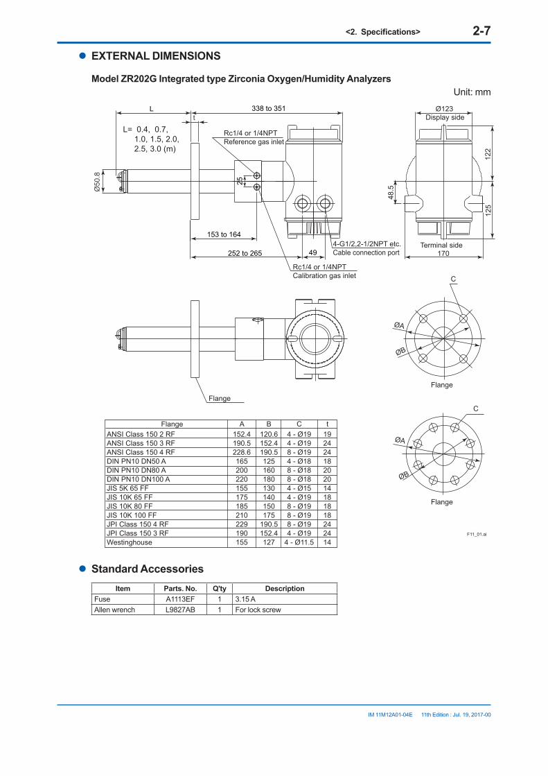
IM 11M12A01-04E 11th Edition : Jul. 19, 2017-00
l EXTERNAL DIMENSIONS
Model ZR202G Integrated type Zirconia Oxygen/Humidity AnalyzersUnit: mm
F11_01.ai
25
t
153 to 164
125
L
170252 to 265 49
48.5
338 to 351
122
L= 0.4, 0.7, 1.0, 1.5, 2.0, 2.5, 3.0 (m)
4-G1/2,2-1/2NPT etc.Cable connection port
Display side
ANSI Class 150 2 RF ANSI Class 150 3 RF ANSI Class 150 4 RF DIN PN10 DN50 A DIN PN10 DN80 A DIN PN10 DN100 A JIS 5K 65 FF JIS 10K 65 FF JIS 10K 80 FF JIS 10K 100 FF JPI Class 150 4 RF JPI Class 150 3 RF Westinghouse
152.4190.5228.6165200220155175185210229190155
120.6152.4190.5125160180130140150175
190.5152.4127
4 - Ø194 - Ø198 - Ø194 - Ø188 - Ø188 - Ø184 - Ø154 - Ø198 - Ø198 - Ø198 - Ø194 - Ø19
4 - Ø11.5
A B C19242418202014181818242414
t
Ø50
.8
Rc1/4 or 1/4NPTReference gas inlet
Rc1/4 or 1/4NPTCalibration gas inlet
Ø123
Terminal side
C
Flange
Flange
ØB
C
Flange
ØA
Flange
ØA
ØB
l Standard AccessoriesItem Parts. No. Q'ty Description
Fuse A1113EF 1 3.15 AAllen wrench L9827AB 1 For lock screw

<2.Specifications> 2-8
IM 11M12A01-04E 11th Edition : Jul. 19, 2017-00
Model ZR202G...-P Integrated type Zirconia Oxygen/Humidity Analyzer with pressure compensation
Unit: mm
F11_02.EPS
Flange
156 ± 3
125
170
256 ± 4 49
48.5
Ø123342 ± 4
25
t
122
Terminal sidePIPING:A
PIPING:B
PIPINGABBABBAABBBBA
ANSI Class 150 2 RF ANSI Class 150 3 RF ANSI Class 150 4 RF DIN PN10 DN50 A DIN PN10 DN80 A DIN PN10 DN100 A JIS 5K 65 FF JIS 10K 65 FF JIS 10K 80 FF JIS 10K 100 FF JPI Class 150 4 RF JPI Class 150 3 RF Westinghouse
152.4190.5228.6165200220155175185210229190155
120.6152.4190.5125160180130140150175
190.5152.4127
4 - Ø194 - Ø198 - Ø194 - Ø188 - Ø188 - Ø184 - Ø154 - Ø198 - Ø198 - Ø198 - Ø194 - Ø19
4 - Ø11.5
A B C19242418202014181818242414
t
L
L= 0.4, 0.7, 1.0, 1.5, 2.0, 2.5, 3.0 (m)
4-G1/2,2-1/2NPT etc.Cable connection port
Ø50
.8
Rc1/4 or 1/4NPTReference gas inlet
Rc1/4 or 1/4NPTCalibration gas inlet
Reference gas outlet
Display side
C
Flange
ØB
C
Flange
ØA
Flange
Stopvalve
ØA
ØB
l Standard AccessoriesItem Parts. No. Q'ty Description
Fuse A1113EF 1 3.15 AAllen wrench L9827AB 1 For lock screw
<2.Specifications> 2-9
IM 11M12A01-04E 11th Edition : Jul. 19, 2017-00
l Hood (Option code /H)Unit: mm
274 150
150
± 4 ± 3
± 3
F13.ai
Material of HOOD : Aluminum Food Weight : Approx. 800g
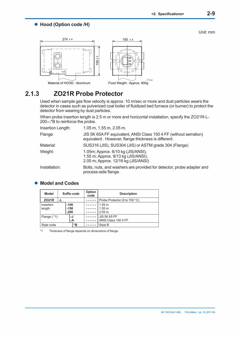
2.1.3 ZO21R Probe ProtectorUsed when sample gas flow velocity is approx. 10 m/sec or more and dust particles wears the detector in cases such as pulverized coal boiler of fluidized bed furnace (or burner) to protect the detector from wearing by dust particles. When probe insertion length is 2.5 m or more and horizontal installation, specify the ZO21R-L-200-*B to reinforce the probe.Insertion Length: 1.05 m, 1.55 m, 2.05 m.Flange: JIS 5K 65A FF equivalent, ANSI Class 150 4 FF (without serration)
equivalent . However, flange thickness is different.Material: SUS316 (JIS), SUS304 (JIS) or ASTM grade 304 (Flange)Weight: 1.05m; Approx. 6/10 kg (JIS/ANSI),
1.55 m; Approx. 9/13 kg (JIS/ANSI), 2.05 m; Approx. 12/16 kg (JIS/ANSI)
Installation: Bolts, nuts, and washers are provided for detector, probe adapter and process-side flange.
l Model and Codes
Model Suffix code Optioncode Description
ZO21R -L - - - - - - Probe Protector (0 to 700 °C)Insertionlength
-100-150-200
- - - - - - - - - - - - - - - - - -
1.05 m1.55 m2.05 m
Flange ( *1) -J-A
- - - - - - - - - - - -
JIS 5K 65 FF ANSI Class 150 4 FF
Style code *B - - - - - - Style B
*1 Thickness of flange depends on dimensions of flange.

<2.Specifications> 2-10
IM 11M12A01-04E 11th Edition : Jul. 19, 2017-00
l EXTERNAL DIMENSIONSUnit: mm
t
F2-3E.ai
D
ØB
CØB
Flange <1>(with bolts, nuts and washer)gasket (t3.0)
SUS316
Dimensions ofholes on opposing surface
ØA
Gas flow
Washer (12)Mounting nut (M12)
l (Insert length)l=1050,1550,2050
Ø60
.5
Flange<1> A B C t DJIS 5K 65 FF 155 130 4 - Ø15 5 40
ANSI Class 150 4 FF 228.6 190.5 8 - Ø19 12 50
2.1.4 ZH21B Dust ProtectorThis protector is designed to protect the probe output from dust agitation (i.e., to prevent combustible materials from entering the probe cell where humidity measurements are made) in a dusty environment.Insertion length: 0.428mFlange: JIS 5K 80 FF or ANSI Class 150 4 FF (However, flange thickness is
different)Material: SUS 316(JIS), SUS304 (JIS) or ASTM grade 304 (flange)Weight: Approximately 6kg (JIS), approximately 8.5kg (ANSI)Mounting: Mounted on the probe or process flange with bolts and associated nuts
and washers.
l Model and Codes
Model Suffix code Optioncode Description
ZH21B - - - - - - - - - - - - - - - - - - - Dust Protector (0 to 600 °C)
Insertion length -40 - - - - - - 0.428 m
Flange ( *1) -J -A
- - - - - - - - - - - -
JIS 5K 80 FF (*1)ANSI Class 150 4B FF (*2)
Style code *B - - - - - - Style B
Note: The flange thickness varies.(*1) Specify the probe ZR22G-040-h-K(*2) Specify the probe ZR22G-040-h-C
<2.Specifications> 2-11
IM 11M12A01-04E 11th Edition : Jul. 19, 2017-00
ZH21B.ai
t
C
C
øB
øB
øA
øB
D
ø72
ø76.
3
428 (Insertion length)
Install facing upwardsJIS flange
ANSI flange
Unit: mm
Flange A B C t DJIS 5K 80 FF 180 145 4 - Ø19 12 40ANSI Class 150 4B FF 228.6 190.5 8 - Ø19 12 50
2.2 ZA8F Flow Setting Unit and ZR20H Automatic Calibration Unit
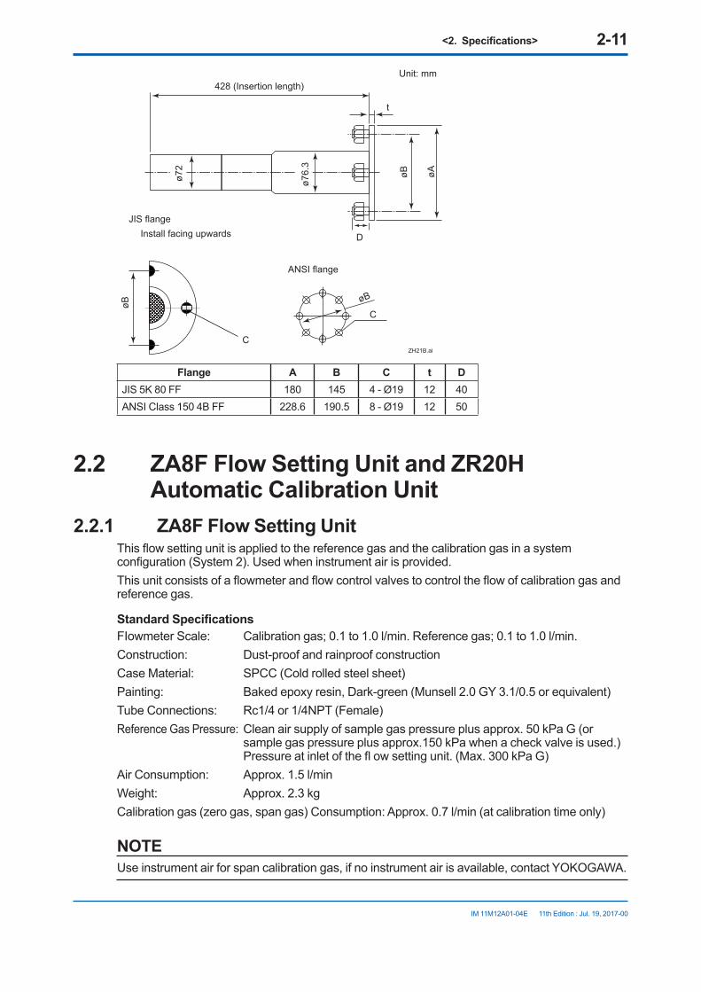
2.2.1 ZA8F Flow Setting UnitThis flow setting unit is applied to the reference gas and the calibration gas in a system configuration (System 2). Used when instrument air is provided.This unit consists of a flowmeter and flow control valves to control the flow of calibration gas and reference gas.
Standard SpecificationsFIowmeter Scale: Calibration gas; 0.1 to 1.0 l/min. Reference gas; 0.1 to 1.0 l/min.Construction: Dust-proof and rainproof constructionCase Material: SPCC (Cold rolled steel sheet)Painting: Baked epoxy resin, Dark-green (Munsell 2.0 GY 3.1/0.5 or equivalent)Tube Connections: Rc1/4 or 1/4NPT (Female)Reference Gas Pressure: Clean air supply of sample gas pressure plus approx. 50 kPa G (or
sample gas pressure plus approx.150 kPa when a check valve is used.) Pressure at inlet of the fl ow setting unit. (Max. 300 kPa G)
Air Consumption: Approx. 1.5 l/minWeight: Approx. 2.3 kgCalibration gas (zero gas, span gas) Consumption: Approx. 0.7 l/min (at calibration time only)
NOTEUse instrument air for span calibration gas, if no instrument air is available, contact YOKOGAWA.
<2.Specifications> 2-12
IM 11M12A01-04E 11th Edition : Jul. 19, 2017-00
l Model and Codes
Model Suffix code Option code Description
ZA8F - - - - - - - - - - - - - - - - - Flow setting unit
Joint -J-A
- - - - - - - - - - - - - - - - - -
Rc 1/4With 1/4 NPT adapter
Style code *C - - - - - - - - - Style C

<2.Specifications> 2-13
IM 11M12A01-04E 11th Edition : Jul. 19, 2017-00
l External Dimensions
CHECKOUT
REFOUT
REFERENCE SPAN ZERO
REFERENCE CHECK
AIRIN
ZEROIN
SPANIN
CHECKOUT
PIPNG INSIDE THE FLOW SETTING UNIT
Unit : mm (inch)
Weight : Approx. 2.3 kg
Flowmeter Flowmeter
ZERO GAS IN
AIR IN
Instrument airApprox. 1.5 l/min.
Air Set
REFOUT
SPAN GAS IN
20 2035 35 35 353570
32
7
222.8235.8
140
180
7
Reference gas outlet
Calibration gas outlet
ø6 Hole
Span gas inletZero gas inlet
2B mounting pipe
Instrument air inlet
F2.6E.ai
Air pressure ;without check valve ; sample gas pressure + approx.50 kPaGwith check valve ; sample gas pressure + approx.150 kPaG
Piping connection port A
ZA8F-J*C
ZA8F-A*C
5 - Rc1/4
5 - 1/4NPT
Model Piping connection port A

<2.Specifications> 2-14
IM 11M12A01-04E 11th Edition : Jul. 19, 2017-00
2.2.2 ZR20H Automatic Calibration UnitThis automatic calibration unit is applied to supply specified flow of reference gas and calibration gas during automatic calibration to the detector in a system configuration (System 3).
l SpecificationsEquipped with the analyzer when automatic calibration is specified in the suffix code of the ZR202G Integrated type by selecting either “-A (Horizontal mounting)” or “-B (Vertical mounting)”. The ZR20H should be arranged when automatic calibration is to be required after the ZR202G has been installed. Ask Yokogawa service station for its mounting.Construction: Dust-proof and rainproof construction; NEMA4X/IP67 (excluding flowmeter)Mounting: Mounted on ZR202G, no vibrationMaterials: Body; Aluminum alloy, Piping; SUS316 (JIS), SUS304 (JIS),
Flowmeter; MA (Methacrylate resin), Bracket; SUS304 (JIS)Finish: Polyurethane corrosion-resistance coating Case; Mint green (Munsell 5.6 BG3.3 /2.9) Cover; Mint green (Munsell 5.6 BG3.3/2.9)Piping Connection: Rc1/4 or 1/4NPT (Female)Power Supply: 24V DC (from ZR202G), Power consumption: Approx.1.3 WReference Gas Pressure: Sample gas pressure plus Approx. 150 kPa (690 kPa max.),
(Pressure at inlet of automatic calibration unit)Air Consumption: Approx. 1.5 l/minWeight: Approx. 2 kgAmbient Temperature: -20 to +55°C, no condensing and freezingAmbient Humidity: 0 to 95% RHStorage Temperature: -30 to +65°C
l Model and Codes
Model Suffix code Option code Description
ZR20H - - - - - - - - - - - - - - - - - - - - - Automatic calibration unit for ZR202G *1
Gas piping connection
-R-T
- - - - - - - - - - - - - - - -
Rc1/41/4NPT (F)
Reference air *2 -E-P
- - - - - - - - - - - - - - - -
Instrument airPressure compensated
Mounting -A-B
- - - - - - - - - - - - - - - -
Horizontal mountingVertical mounting
— -A - - - - - - - - Always -A
*1 Ask Yokogawa service station for additional mounting of ZR20H to the preinstalled ZR202G.*2 Select the appropriate reference gas of ZR20H according to the one of ZR202G.

<2.Specifications> 2-15
IM 11M12A01-04E 11th Edition : Jul. 19, 2017-00
l External Dimensions
(1) Horizontal Mounting (-A)
Rc1/4 or 1/4NPT(Female)
Rc1/4 or 1/4NPT(Female)
Rc1/4 or 1/4NPT(Female)
Rc1/4 or 1/4NPT(Female)Rc1/4 or 1/4NPT(Female)
Rc1/4 or 1/4NPT(Female)
SPAN IN REF IN ZERO IN
AUTO CAL. UNIT
-20 TO 558C
ZR20HMODELSUFFIX
STYLE
AMB.TEMP
NO.
S1SUPPLY 690kPa MAX.
USED WITH ZR202G
ZR202GUSED WITH
690kPa MAX.SUPPLYS1
NO.
AMB.TEMP
STYLE
SUFFIXMODEL ZR20H
-20 TO 558C
AUTO CAL. UNIT
SPAN IN REF IN ZERO IN
[ 84
166.5
Ø80
243 25
8
166.5
5644
180MAX444040 66.5
4911
1
66.540 40
Ø84
Span gas inlet
Zero gas inlet
Reference gas inlet
Zero gas inlet
Reference gas inlet
Span gas inlet
MAX
(2) Vertical Mounting (-B)
Unit: mm
Ø80
44
PIPNG INSIDE THE AUTOMATIC CALIBRATION UNIT
SPAN IN
REF. IN
ZERO IN
F4.11E.ai
Calibration gasReference gas
ZR202G body
Span gas solenoid valve
Span gas flowmeter
Reference gas flowmeter
To Air set
To Zero gas cylinder
Needle valve
Automatic calibration unitZero gas flowmeter
Zero gas solenoid valve
Check valve

<2.Specifications> 2-16
IM 11M12A01-04E 11th Edition : Jul. 19, 2017-00
2.3 ZO21S Standard Gas UnitThis is a handy unit to supply zero gas and span gas to the detector in a system configuration based on System 1. It is used in combination with the detector only during calibration.The ZO21S does not conform to CE marking.
l Standard SpecificationsFunction: Portable unit for calibration gas supply consisting of span gas (air) pump, zero
gas cylinder with sealed inlet, flow rate checker and flow rate needle valve.Sealed Zero Gas Cylinders (6 provide): E7050BACapacity: 1 lFilled pressure: Approx. 686 kPa G (at 35 °C)Composition: 0.95 to 1.0 vol% O2 (N2 balanced)Power Supply: 100, 110, 115, 200, 220, 240V AC± 10%, 50/60 HzPower Consumption: Max. 5 VACase material: SPCC (Cold rolled steel sheet)Paint: Epoxy resin, bakedPaint Color: Mainframe; Munsell 2.0 GY3.1/0.5 equivalent Cover; Munsell 2.8 GY6.4/0.9 equivalentPiping: Ø6 x Ø4mm flexible tube connectionWeight: Approx. 3 kgSpan gas: Internal pump draws in air from atmosphere, and feeds to detector.
l Model and Codes
Model Suffix code Option code DescriptionZO21S - - - - - - - - - - - - - - - - - - - - - - - - Standard gas unit
Power supply
-2-3-4-5-7-8
- - - - - - - - - - - - -- - - - - - - - - - - - -- - - - - - - - - - - - -- - - - - - - - - - - - -- - - - - - - - - - - - -- - - - - - - - - - - - -
200 V AC 50/60 Hz220 V AC 50/60 Hz240 V AC 50/60 Hz100 V AC 50/60 Hz110 V AC 50/60 Hz115 V AC 50/60 Hz
Panel -J-E
- - - - - - - - - - - - - - - - - - - - - - - - - -
Japanese versionEnglish version
Style code *A - - - - - - - - - - - - - Style A
l External Dimensions
92
228
253
1600
354
Flow checkerSpan gas valve
Zero gas valveGas outlet
F24.aiZero gas cylinder (6 cylinder): E7050BA

<2.Specifications> 2-17
IM 11M12A01-04E 11th Edition : Jul. 19, 2017-00
2.4 Other Equipment2.4.1 Dust Filter for Oxygen Analyzer (part no. K9471UA)
This filter is used to protect the detector sensor from corrosive dust components or from a high concentration of dust when the oxygen concentration in utility boilers or concrete kilns are to be measured.This filter requires the measuring gas flow of 1 m/sec or faster to replace gas inside zirconia sensor.
l Standard specificationApplicable detector: Standard-type detector for general use (the sample gas flow should be
approximately perpendicular to the probe.)Mesh: 30 micronsMaterial: SiC (Filter), SUS316 (JIS)Weight: Approx. 0.2 kg
Part No. DescriptionK9471UA Filter
K9471UX Tool
Unit: mm
Ø51
32
10
Carborundum filter (SiC)
Increasing of insertion lengthF31.EPS
Screw
Detector
Attach the filterunit to the tip of the detector by screwing it clockwise.
2.4.2 Dust Guard Protector (K9471UC)Recommended to be used when sample gas is likely to flow directly into the cell due to its flow direction in the stack or the like, flammable dust may go into the cell, or water drops are likely to fall and remain in the cell during downtime or the like due to the installation position.Material: SUS316Weight: Approx. 0.3 kg
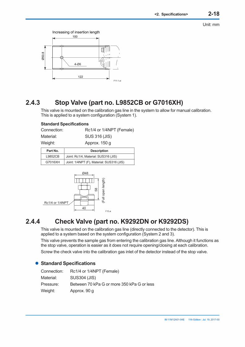
<2.Specifications> 2-18
IM 11M12A01-04E 11th Edition : Jul. 19, 2017-00
Unit: mm
4-Ø6
122
Ø50
.8
100Increasing of insertion length
F11-1.ai
2.4.3 Stop Valve (part no. L9852CB or G7016XH)This valve is mounted on the calibration gas line in the system to allow for manual calibration. This is applied to a system configuration (System 1).
Standard SpecificationsConnection: Rc1/4 or 1/4NPT (Female)Material: SUS 316 (JIS)Weight: Approx. 150 g
Part No. DescriptionL9852CB Joint: Rc1/4, Material: SUS316 (JIS)
G7016XH Joint: 1/4NPT (F), Material: SUS316 (JIS)
F15.ai
58
(Ful
l ope
n le
ngth
)
40
Rc1/4 or 1/4NPT
Ø48
2.4.4 Check Valve (part no. K9292DN or K9292DS)This valve is mounted on the calibration gas line (directly connected to the detector). This is applied to a system based on the system configuration (System 2 and 3).This valve prevents the sample gas from entering the calibration gas line. Although it functions as the stop valve, operation is easier as it does not require opening/closing at each calibration.Screw the check valve into the calibration gas inlet of the detector instead of the stop valve.
l Standard SpecificationsConnection: Rc1/4 or 1/4NPT (Female)Material: SUS304 (JIS)Pressure: Between 70 kPa G or more 350 kPa G or lessWeight: Approx. 90 g

<2.Specifications> 2-19
IM 11M12A01-04E 11th Edition : Jul. 19, 2017-00
Part No. DescriptionK9292DN Joint: Rc 1/4, Material: SUS304 (JIS)
K9292DS Joint: 1/4 NPT (F), Material: SUS304 (JIS)
K9292DN : Rc 1/4(A),R 1/4(B)K9292DS : 1/4FNPT(A),1/4NPT(Male)(B)
F30.EPS
Approx. 19 Approx. 54
Unit: mm
A B
2.4.5 Air SetThis set is used to lower the pressure when instrument air is used as the reference and span gases.
l Standard Specifications
Part no. G7003XF or K9473XKPrimary Pressure: Max. 1 MPa GSecondary Pressure: 0.02 to 0.2 MPa GConnection: Rc1/4 or 1/4NPT (F) with joint adapterWeight: Approx.1 kg
Part No. Description
G7003XF Joint: Rc1/4, Material: Zinc alloy
K9473XK Joint: 1/4 NPT (F), Material: Zinc alloy with adapter
Part. no. G7004XF or K9473XGPrimary Pressure: Max. 1 MPa GSecondary Pressure: 0.02 to 0.5 MPa GConnection: Rc1/4 or 1/4NPT (F) with joint adapterWeight: Approx. 1 kg
Part No. Description
G7004XF Joint: Rc1/4, Material: Zinc alloy
K9473XG Joint: 1/4 NPT (F), Material: Zinc alloy with adapter
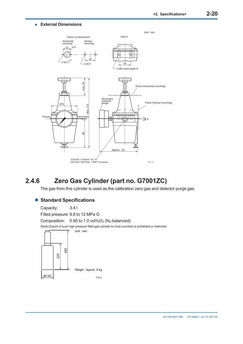
<2.Specifications> 2-20
IM 11M12A01-04E 11th Edition : Jul. 19, 2017-00
l External Dimensions
Ø74
Primary Secondary
88
Max
. 210
max
. 55
Approx. 122
Secondarypressuregauge
Panel (Horizontal mounting)
Panel (Vertical mounting)
G7003XF, G7004XF: Rc 1/4K9473XK, K9473XG: 1/4NPT connector
A
22 ø15
2-ø2.2 +0.5 -0
2-ø6.5
40
2-M6 screw depth 8
40
Horizontal mounting
Vertical mounting
Panel cut dimensions View A
F22_1.ai
Unit : mm
2.4.6 Zero Gas Cylinder (part no. G7001ZC)The gas from this cylinder is used as the calibration zero gas and detector purge gas.
l Standard SpecificationsCapacity: 3.4 lFilled pressure: 9.8 to 12 MPa GComposition: 0.95 to 1.0 vol%O2 (N2-balanced)(Note) Export of such high pressure filled gas cylinder to most countries is prohibited or restricted.
Unit : mm
Weight : Approx. 6 kg
F32.ai
485
325
ø140

<2.Specifications> 2-21
IM 11M12A01-04E 11th Edition : Jul. 19, 2017-00
2.4.7 Pressure Regulator (G7013XF or G7014XF) for Gas Cylinder
This regulator valve is used with the zero gas cylinders.
l Standard SpecificationsPrimary Pressure: Max. 14.8 MPa GSecondary Pressure: 0 to 0.4 MPa GConnection: Inlet; W22 14 threads, right hand screw Outlet; Rc1/4 or 1/4NPT (Female)Material: Brass body
HI HAC
AKT O
Regulator handleW22 (Right-handed screw)Stop valve
App
rox.
112
IN
Unit : mm
* Outlet
Part No. G7013XFG7014XF
* OutletRc1/41/4 NPT female screw
Secondarypressure gauge
Primarypressure gauge
Secondary safety valve
Primary safety valve
Approx. 82Approx. 59
Approx. 163 Approx. 174
2.4.8 Case Assembly (E7044KF) for Calibration gas Cylinder
This case is used to store the zero gas cylinders.
l Standard SpecificationsInstallation: 2B pipe mountingMaterial: SPCC (Cold rolled steel sheet)Case Paint: Baked epoxy resin, Jade green (Munsell 7.5 BG 4/1.5)Weight: Approx. 10 kg with gas cylinder(Note) Export of such high pressure filled gas cylinders to most countries is prohibited or restricted.

<2.Specifications> 2-22
IM 11M12A01-04E 11th Edition : Jul. 19, 2017-00
324
496
200180
Pressure regulator
Zero gas cylinder
2B mounting pipe ( Ø60.5 )
(G7001ZC)
G7013XF/G7014XF
F23.ai
(Note)The zero gas cylinder and the regulator valve are not included in the E7044KF (case assembly)
(158.3)
(160)
The oblique line is an opening portion.
2.4.9 ZR202A Heater Assemblyl Model and Codes
Model Suffix code Option code DescriptionZR202A - - - - - - - - - - - - - - - - - - - - Heater Assembly for ZR202G
Length (*1) -040-070-100-150-200-250-300
- - - - - - - - - - - - - - - - - - - - - -- - - - - - - - - - - - - - - - - - - - - - - - - - - - - - - - - - - - - - - - - - - - - - - - - - - - - - -
0.4 m0.7 m1 m1.5 m2 m2.5 m3 m
Jig for change -A-N
- - - - - - - - - - - - - - - - - - - - - -
with JigNone
― -A - - - - - - - - - - - Always -A
*1 Suffix code of length should be selected as same as ZR202G installed.(Note) The heater is made of ceramic, do not drop or subject it to pressure stress.
l External Dimensions
K94
70B
X
ZR202A-040ZR202A-070ZR202A-100ZR202A-150ZR202A-200ZR202A-250ZR202A-300
55285211521652215226523152
Approx. 0.8Approx. 1.2Approx. 1.6Approx. 2.2Approx. 2.8Approx. 3.4Approx. 4.0
Jig for change
L±12
(K9470BX) Ø 2
1.7
30
Unit : mm
Ø 4
5
L: length
L Weight (kg)Model & Code
F2.16.EPS
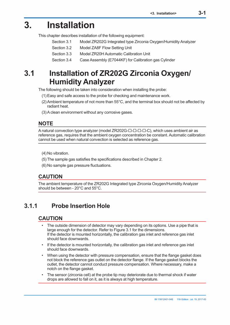
<3. Installation> 3-1
IM 11M12A01-04E 11th Edition : Jul. 19, 2017-00
3. InstallationThis chapter describes installation of the following equipment: Section 3.1 Model ZR202G Integrated type Zirconia Oxygen/Humidity Analyzer Section 3.2 Model ZA8F Flow Setting Unit Section 3.3 Model ZR20H Automatic Calibration Unit Section 3.4 Case Assembly (E7044KF) for Calibration gas Cylinder
3.1 Installation of ZR202G Zirconia Oxygen/Humidity Analyzer
The following should be taken into consideration when installing the probe:(1) Easy and safe access to the probe for checking and maintenance work.(2) Ambient temperature of not more than 55°C, and the terminal box should not be affected by
radiant heat.(3) A clean environment without any corrosive gases.
NOTEA natural convection type analyzer (model ZR202G-----C), which uses ambient air as reference gas, requires that the ambient oxygen concentration be constant. Automatic calibration cannot be used when natural convection is selected as reference gas.
(4) No vibration.(5) The sample gas satisfies the specifications described in Chapter 2.(6) No sample gas pressure fluctuations.
CAUTIONThe ambient temperature of the ZR202G Integrated type Zirconia Oxygen/Humidity Analyzer should be between - 20°C and 55°C.
3.1.1 Probe Insertion Hole
CAUTION• The outside dimension of detector may vary depending on its options. Use a pipe that is
large enough for the detector. Refer to Figure 3.1 for the dimensions. If the detector is mounted horizontally, the calibration gas inlet and reference gas inlet should face downwards.
• If the detector is mounted horizontally, the calibration gas inlet and reference gas inlet should face downwards.
• When using the detector with pressure compensation, ensure that the flange gasket does not block the reference gas outlet on the detector flange. If the flange gasket blocks the outlet, the detector cannot conduct pressure compensation. Where necessary, make a notch on the flange gasket.
• The sensor (zirconia cell) at the probe tip may deteriorate due to thermal shock if water drops are allowed to fall on it, as it is always at high temperature.
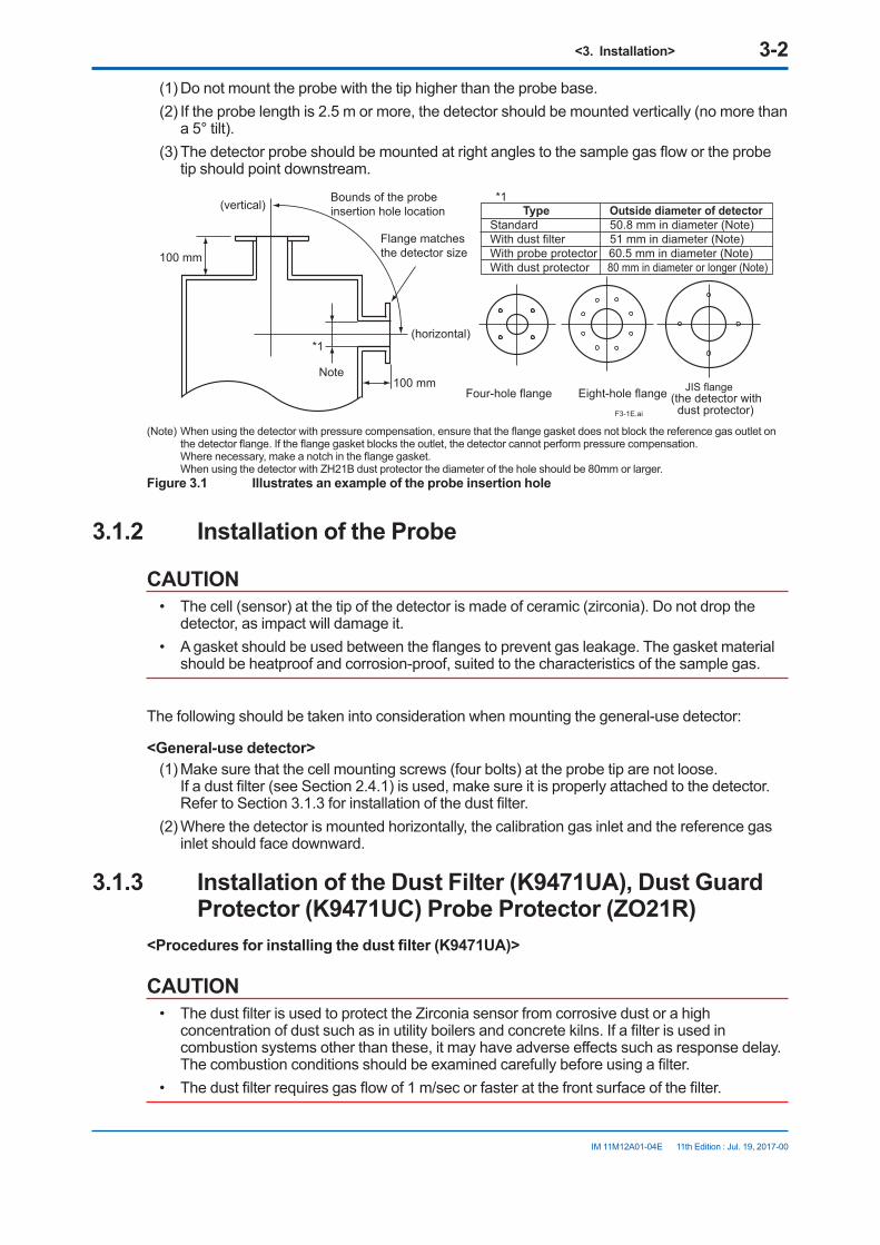
<3. Installation> 3-2
IM 11M12A01-04E 11th Edition : Jul. 19, 2017-00
(1) Do not mount the probe with the tip higher than the probe base.(2) If the probe length is 2.5 m or more, the detector should be mounted vertically (no more than
a 5° tilt).(3) The detector probe should be mounted at right angles to the sample gas flow or the probe
tip should point downstream.
100 mm
100 mm
F3-1E.ai
(vertical)Bounds of the probe insertion hole location
Flange matches the detector size
(horizontal)
Note
Type Outside diameter of detectorStandard 50.8 mm in diameter (Note)With dust filter 51 mm in diameter (Note)With probe protector 60.5 mm in diameter (Note)With dust protector 80 mm in diameter or longer (Note)
Four-hole flange Eight-hole flange
*1
*1
JIS flange(the detector with dust protector)
(Note) When using the detector with pressure compensation, ensure that the flange gasket does not block the reference gas outlet on the detector flange. If the flange gasket blocks the outlet, the detector cannot perform pressure compensation.
Where necessary, make a notch in the flange gasket. When using the detector with ZH21B dust protector the diameter of the hole should be 80mm or larger.Figure 3.1 Illustrates an example of the probe insertion hole
3.1.2 Installation of the Probe
CAUTION• The cell (sensor) at the tip of the detector is made of ceramic (zirconia). Do not drop the
detector, as impact will damage it.• A gasket should be used between the flanges to prevent gas leakage. The gasket material
should be heatproof and corrosion-proof, suited to the characteristics of the sample gas.
The following should be taken into consideration when mounting the general-use detector:
<General-use detector>(1) Make sure that the cell mounting screws (four bolts) at the probe tip are not loose.
If a dust filter (see Section 2.4.1) is used, make sure it is properly attached to the detector. Refer to Section 3.1.3 for installation of the dust filter.
(2) Where the detector is mounted horizontally, the calibration gas inlet and the reference gas inlet should face downward.
3.1.3 Installation of the Dust Filter (K9471UA), Dust Guard Protector (K9471UC) Probe Protector (ZO21R)
<Procedures for installing the dust filter (K9471UA)>
CAUTION• The dust filter is used to protect the Zirconia sensor from corrosive dust or a high
concentration of dust such as in utility boilers and concrete kilns. If a filter is used in combustion systems other than these, it may have adverse effects such as response delay. The combustion conditions should be examined carefully before using a filter.
• The dust filter requires gas flow of 1 m/sec or faster at the front surface of the filter.

<3. Installation> 3-3
IM 11M12A01-04E 11th Edition : Jul. 19, 2017-00
When you specify option code /F1, the detector is shipped with the dust filter mounted.Follow this procedure when replacing the filter in the detector. It is recommended that you read Chapter 11 prior to filter mounting, for it is necessary to be familiar with the detector’s construction, especially the sensor assembly.
(1) Mount the dust filter by putting it on the end of the detector and screw the dust filter clockwise. Put a hook pin wrench (K9471UX), Ø52 to 55 in diameter, into the hole on the dust filter to fasten or remove it. Apply a heat-resistant coating (see Note 1) to the threads on the detector. Where mounting dust filter after having once removed it from the detector, reapply the heat-resistant coating.
Note 1: As the detector is heated to 700°C, it is recommended to use the heat-resistant coating on the threads to prevent seizing up. Name of heat-resistant coating material: “Never-Seez Nickel Special”.
Ø51
32
10
Carborundum filter (SiC)
Increasing of insertion lengthF31.EPS
Screw
Detector
Attach the filter unit to the tip of the detector by screwing it clockwise.
Figure 3.2 Installation of the dust filter
<Procedures for installing the dust guard protector (K9471UC)>The ZR202G is shipped with the dust guard protector when the option code /F2 is specified in case of ordering the detector. The protector should be used when preventing dusts and water drops from lowering the detector performance is desired. Screw the protector on the top of the detector so as to cover the top. When attaching or detaching the protector, perform by hooking holes of its side with a hook pin wrench for Ø52-55 hole( Pin diameter 4.5 mm: P/N K9471UX or the like) or by pass a screwdriver through the holes. When re-attaching the protector after detaching it, apply the “Never-Seez Nickel Special” to it.
4-Ø6
122
Ø50
.8
100
Increasing of insertion length
F11-1.ai
Figure 3.3 Installation of the dust guard protector
<Detector with a probe protector (Model ZO21R-L-200- *B for enhance forth>The detector is used with a probe protector to support the probe (ZR202G) when the probe length is 2.5m or more and mounted horizontally.
(1) Put a gasket (provided by the user) between the flanges and mount the probe protector in the probe insertion hole.
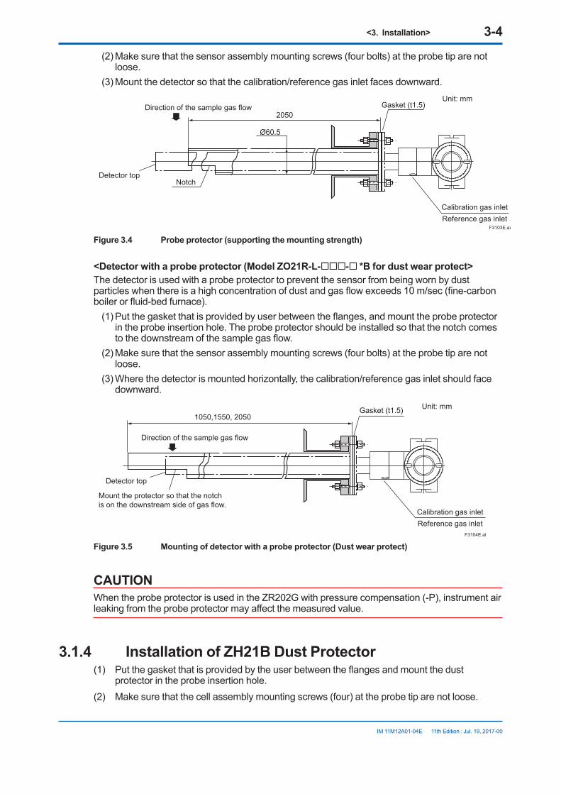
<3. Installation> 3-4
IM 11M12A01-04E 11th Edition : Jul. 19, 2017-00
(2) Make sure that the sensor assembly mounting screws (four bolts) at the probe tip are not loose.
(3) Mount the detector so that the calibration/reference gas inlet faces downward.
2050
Ø60.5
Notch
Unit: mm
F3103E.ai
Gasket (t1.5)
Calibration gas inletReference gas inlet
Direction of the sample gas flow
Detector top
Figure 3.4 Probe protector (supporting the mounting strength)
<Detector with a probe protector (Model ZO21R-L-- *B for dust wear protect>The detector is used with a probe protector to prevent the sensor from being worn by dust particles when there is a high concentration of dust and gas flow exceeds 10 m/sec (fine-carbon boiler or fluid-bed furnace).
(1) Put the gasket that is provided by user between the flanges, and mount the probe protector in the probe insertion hole. The probe protector should be installed so that the notch comes to the downstream of the sample gas flow.
(2) Make sure that the sensor assembly mounting screws (four bolts) at the probe tip are not loose.
(3) Where the detector is mounted horizontally, the calibration/reference gas inlet should face downward.
Direction of the sample gas flow
Mount the protector so that the notchis on the downstream side of gas flow.
F3104E.ai
1050,1550, 2050Gasket (t1.5) Unit: mm
Detector top
Calibration gas inletReference gas inlet
Figure 3.5 Mounting of detector with a probe protector (Dust wear protect)
CAUTIONWhen the probe protector is used in the ZR202G with pressure compensation (-P), instrument air leaking from the probe protector may affect the measured value.
3.1.4 Installation of ZH21B Dust Protector(1) Put the gasket that is provided by the user between the flanges and mount the dust
protector in the probe insertion hole.(2) Make sure that the cell assembly mounting screws (four) at the probe tip are not loose.

<3. Installation> 3-5
IM 11M12A01-04E 11th Edition : Jul. 19, 2017-00
(3) Mount the detector so that the calibration gas inlet and the reference gas inlet face downward.
F3-2E.ai
Unit : mm
Reference gas inletCalibration gas inlet
F3-2E.ai
Unit : mm
Figure 3.6 Installation of the dust filter
3.2 Installation of ZA8F Flow Setting UnitThe following should be taken into consideration:
(1) Easy access to the unit for checking and maintenance work.(2) Near to the detector and the converter(3) No corrosive gas.(4) An ambient temperature of not more than 55°C and little changes of temperature.(5) No vibration.(6) Little exposure to rays of the sun or rain.
n Mounting of ZA8F Flow Setting UnitThe flow setting unit can be mounted either on a pipe (nominal JIS 50 A) or on a wall. It should be positioned vertically so that the flowmeter works correctly.
<Pipe Mounting>(1) Prepare a vertical pipe of sufficient strength (nominal JIS 50A: O.D. 60.5 mm) for mounting
the flow setting unit. (The unit weighs approximately 2 to 3.5 kg.) (2) Mount the flow setting unit on the pipe by tightening the nuts with the U-bolt so that the metal
fitting is firmly attached to the pipe.
F3401E.ai
Figure 3.7 Pipe Mounting
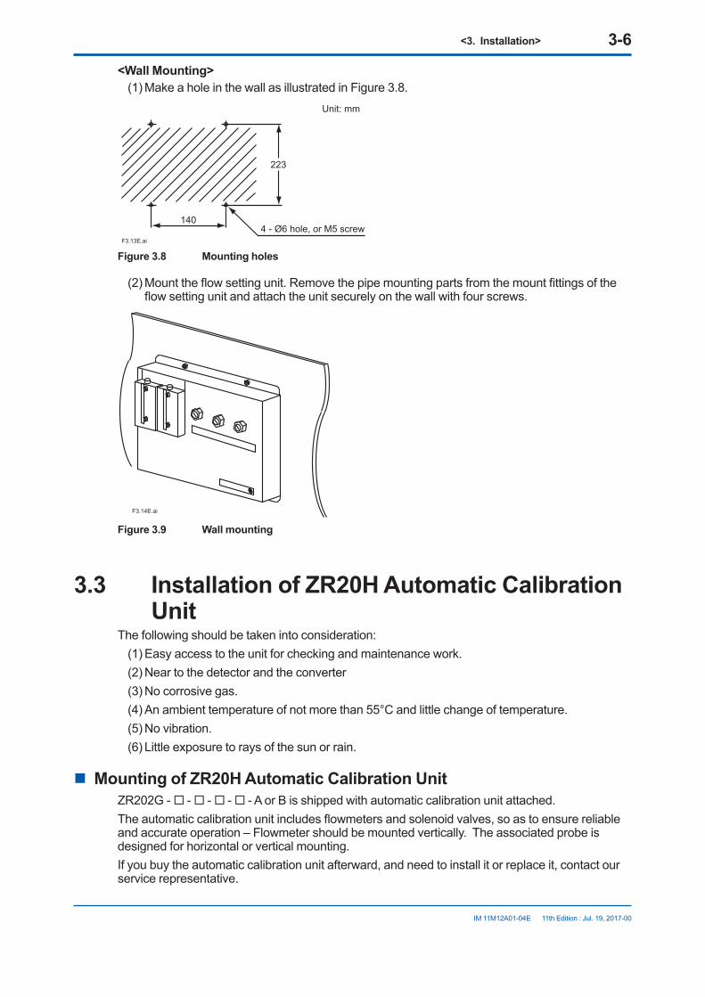
<3. Installation> 3-6
IM 11M12A01-04E 11th Edition : Jul. 19, 2017-00
<Wall Mounting>(1) Make a hole in the wall as illustrated in Figure 3.8.
223
140
F3.13E.ai
4 - Ø6 hole, or M5 screw
Unit: mm
Figure 3.8 Mounting holes
(2) Mount the flow setting unit. Remove the pipe mounting parts from the mount fittings of the flow setting unit and attach the unit securely on the wall with four screws.
F3.14E.ai
Figure 3.9 Wall mounting
3.3 Installation of ZR20H Automatic Calibration Unit
The following should be taken into consideration:(1) Easy access to the unit for checking and maintenance work.(2) Near to the detector and the converter(3) No corrosive gas.(4) An ambient temperature of not more than 55°C and little change of temperature.(5) No vibration.(6) Little exposure to rays of the sun or rain.
n Mounting of ZR20H Automatic Calibration UnitZR202G - - - - - A or B is shipped with automatic calibration unit attached. The automatic calibration unit includes flowmeters and solenoid valves, so as to ensure reliable and accurate operation – Flowmeter should be mounted vertically. The associated probe is designed for horizontal or vertical mounting. If you buy the automatic calibration unit afterward, and need to install it or replace it, contact our service representative.

<3. Installation> 3-7
IM 11M12A01-04E 11th Edition : Jul. 19, 2017-00
Zero gas inlet Rc1/4 or 1/4NPT(Female)
Reference gas inletRc1/4 or 1/4NPT(Female)
Terminal box side
Span gas inletRc1/4 or 1/4NPT(Female)
166.5
258
243
214 MAX44 66.540 40
Vertical mounting on the ZR202G (-B)
F3.15E.ai
Horizontal mounting on the ZR202G (-A) Unit: mmDisplay side
Zero gas inletRc1/4 or 1/4NPT(Female)
Span gas inletRc1/4 or 1/4NPT(Female)
Reference gas inletRc1/4 or 1/4NPT(Female)
166.5
604516
0
66.540 40180 MAX44
Figure 3.10 Automatic Calibration Unit Mounting
3.4 Installation of the Case Assembly (E7044KF) for Calibration Gas Cylinder
The case assembly is used to store the G7001ZC zero gas cylinders.
The following should be taken into consideration:(1) Easy access for cylinder replacement(2) Easy access for checking(3) Near to the detector and converter as well as the flow setting unit.(4) The temperature of the case should not exceed 40°C due to rays of the sun or radiated
heat.(5) No vibration
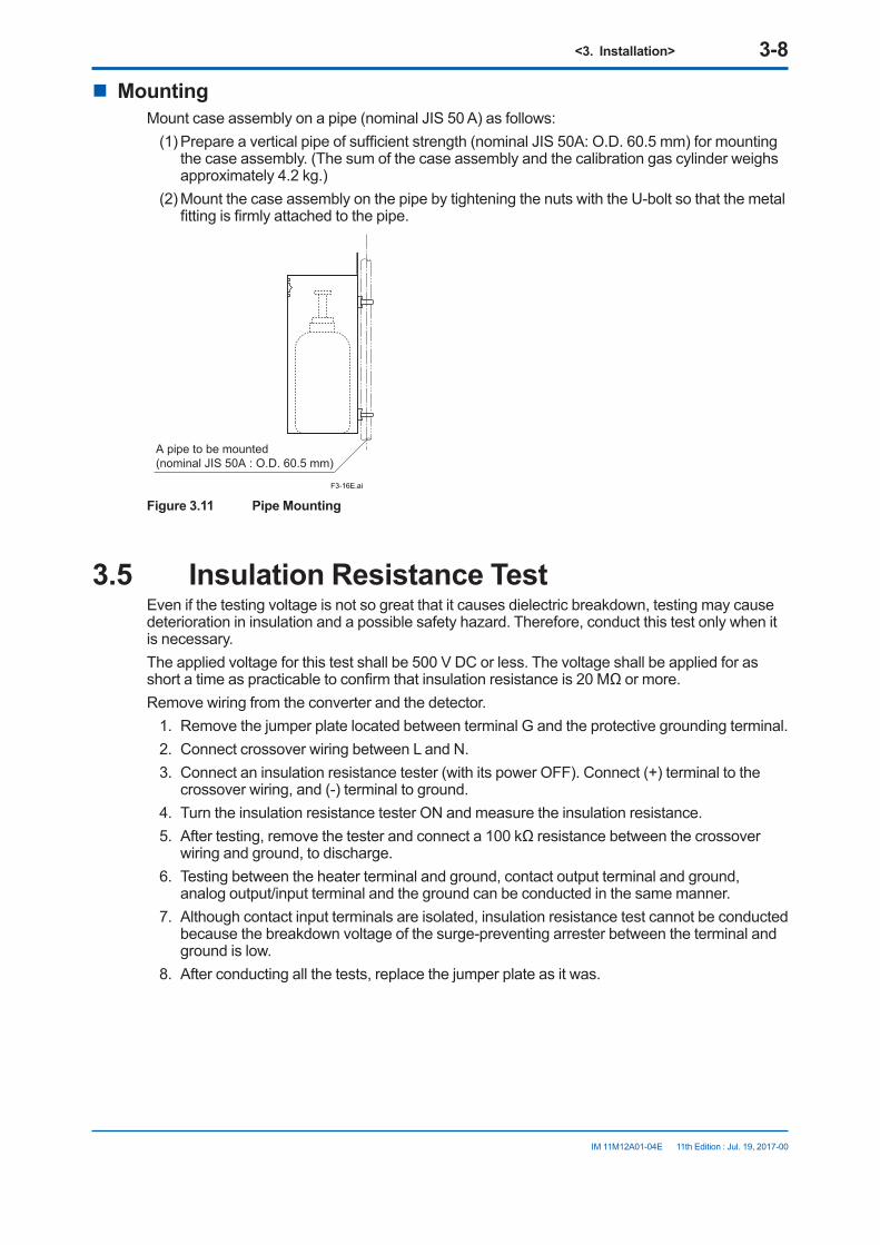
<3. Installation> 3-8
IM 11M12A01-04E 11th Edition : Jul. 19, 2017-00
n MountingMount case assembly on a pipe (nominal JIS 50 A) as follows:
(1) Prepare a vertical pipe of sufficient strength (nominal JIS 50A: O.D. 60.5 mm) for mounting the case assembly. (The sum of the case assembly and the calibration gas cylinder weighs approximately 4.2 kg.)
(2) Mount the case assembly on the pipe by tightening the nuts with the U-bolt so that the metal fitting is firmly attached to the pipe.
F3-16E.ai
A pipe to be mounted (nominal JIS 50A : O.D. 60.5 mm)
Figure 3.11 Pipe Mounting
3.5 Insulation Resistance TestEven if the testing voltage is not so great that it causes dielectric breakdown, testing may cause deterioration in insulation and a possible safety hazard. Therefore, conduct this test only when it is necessary.The applied voltage for this test shall be 500 V DC or less. The voltage shall be applied for as short a time as practicable to confirm that insulation resistance is 20 MΩ or more.Remove wiring from the converter and the detector.
1. Remove the jumper plate located between terminal G and the protective grounding terminal.2. Connect crossover wiring between L and N.3. Connect an insulation resistance tester (with its power OFF). Connect (+) terminal to the
crossover wiring, and (-) terminal to ground.4. Turn the insulation resistance tester ON and measure the insulation resistance.5. After testing, remove the tester and connect a 100 kΩ resistance between the crossover
wiring and ground, to discharge.6. Testing between the heater terminal and ground, contact output terminal and ground,
analog output/input terminal and the ground can be conducted in the same manner.7. Although contact input terminals are isolated, insulation resistance test cannot be conducted
because the breakdown voltage of the surge-preventing arrester between the terminal and ground is low.
8. After conducting all the tests, replace the jumper plate as it was.

<3. Installation> 3-9
IM 11M12A01-04E 11th Edition : Jul. 19, 2017-00
1DI-1
2DI-2
3DI-C
4DO-1
5DO-1
6DO-2
7DO-2
8FG
9AO(+)
10AO(-)
11L
12N
13G
14FG
F3.17E.ai
Remove jumper plate
Insulation resistance
tester
Insulation resistance
tester
Crossover wiring
Crossover wiring
Contact input 1
Contact input 2+-
+-
Insulation resistance
tester +-
Figure 3.12

Blank Page

<4. Piping> 4-1
IM 11M12A01-04E 11th Edition : Jul. 19, 2017-00
4. PipingThis chapter describes piping procedures in the three typical system configurations for EXAxt ZR Integrated type Zirconia Oxygen/Humidity Analyzer.
• Ensure that each check valve, stop valve and joints used for piping are not leaking. Especially, when there is any leakage at piping and joints for the calibration gas, it may cause clogging of the piping or incorrect calibration.
• Be sure to conduct leakage test after setting the piping.• Basically, apply instrument air (dehumidified to the dew point -20°C or lower, removed any
dust, oil mist and the like) for the reference gas when piping.• When the instrument applies natural convection for reference gas (Model ZR202G-----C), ambient air near the probe is used for reference gas; therefore the accuracy of analysis will be affected by ambient humidity changes or the like. If more accurate analysis is necessary, use instrument air (dehumidified to the dew point -20°C or lower, removed any dust, oil mist and the like) for reference gas. Stable analyzing can be conducted when using instrument air.
4.1 Piping for System 1The piping in System 1 is illustrated in Figure 4.1
~
ZR202G Integrated type Zirconia Oxygen/Humidity Analyzer
ZO21S Standard gas unit
Stop valve
Calibration gas
F1.1E.ai
~
100 to 240 V AC
100/110/115/200/220/240 V AC
Contact inputAnalog output, contact outputDigital output (HART)
Figure 4.1 Piping for System 1
Piping in System 1 is as follows:• Place a stop valve through the nipple at the calibration gas inlet of the equipment.
Then mount a joint for a 6 mm (O.D.) x 4 mm (I.D.) soft tube at the stop valve connection hole of the inlet side (see Section 4.1.2). The tube is to be connected to this joint only during calibration.
CAUTION• The stop valve should be connected directly to the equipment. If any piping is present
between the analyzer and the stop valve, condensed water may be produced in the pipe, which may cause damage to the sensor by rapid cooling when the calibration gas is introduced.
• The reference gas should have an oxygen concentration identical to that of fresh air (21%).

<4. Piping> 4-2
IM 11M12A01-04E 11th Edition : Jul. 19, 2017-00
4.1.1 Piping Parts for System 1Check that the parts listed in Table 4.1 are provided.
Table 4.1 Piping Parts
Equipment Piping location Parts Name DescriptionOxygen/Humidity Analyzer
Calibration gas inlet Stop valve (L9852CB or G7016XH) recommended by YOKOGAWA
Nipple * Rc1/4 or 1/4 NPT General partsJoint for tube connection
Rc1/4 (1/4NPT) for a 6x4mm soft tube
General parts
Reference gas inlet (Sealed up) (when piping is required, refer to Section 4.1.3)
Note: Parts with marking * are used when required. General parts can be found on the local market.
4.1.2 Piping for the Calibration GasWhen carrying out calibration, connect the piping (6(O.D) x 4(I.D.) mm tube) from the standard gas unit to the calibration gas inlet of the oxygen analyzer. Mount the stop valve (of a quality specified by YOKOGAWA) through a nipple (found on the local market) as illustrated in Figure 4.2, and mount a joint (also found on the local market) at the stop valve tip. (The stop valve may be mounted on the equipment when the oxygen analyzer is shipped.)Note: Mount the stop valve in the vicinity of the equipment.
F4.2E.ai
Stop valve
Tube connection joint
Nipple
Figure 4.2 Piping for the Calibration Gas Inlet
4.1.3 Piping for the Reference Gas• Normally, no piping is required for the reference gas inlet when the equipment applies
natural convection for reference gas (models ZR202G-----C). Leave the plug as it is. If the air around the probe is polluted and the necessary oxygen concentration (21 vol%O2) cannot be obtained, make instrument air piping as in Section 4.2, System 2.
• When the equipment uses instrument air for the reference gas, piping is required as described in Section 4.2, System 2 (models ZR202G-----E or P).
4.2 Piping for System 2Piping in System 2 is illustrated in Figure 4.3.

<4. Piping> 4-3
IM 11M12A01-04E 11th Edition : Jul. 19, 2017-00
~
ZR202G Integrated type Zirconia Oxygen/Humidity Analyzer
F1.2E.ai
ZA8F flow setting unit
Reference gas
Calibration gas
Needle valveFlowmeter
Instrument air
Air Set
Pressure regulator Zero gas cylinder
Calibration gas unit case
Stop valveor
Check valve
Span gas(Same as Zero gas calibration)
100 to 240 V ACContact inputAnalog output, contact outputDigital output (HART)
Figure 4.3 Piping for System 2
System 2 illustrated in Figure 4.3 requires piping as follows:• Mount the check valve or the stop valve through a nipple to the calibration gas inlet of the
equipment.
4.2.1 Piping Parts for System 2Check that the parts listed in Table 4.2 are provided.
Table 4.2 Piping Parts
Equipment Piping location Parts Name DescriptionOxygen/Humidity Analyzer
Calibration gas inlet Stop valve or check valve
Stop valve (L9852CB or G7016XH recommended by YOKOGAWACheck valve (K9292DN or K9292DS) provided by YOKOGAWA
Nipple * Rc1/4 or 1/4 NPT General partsZero gas cylinder User' s scopePressure Regulator (G7013XF or G7014XF) recommended by
YOKOGAWAJoint for tube connection Rc1/4 or 1/4 NPT General parts
Reference gas inlet Air set (G7003XF/K9473XK or G7004XF/K9473XG) recommended by YOKOGAWA
Joint for tube connection Rc1/4 or 1/4 NPT General parts
Note: Parts with marking * are used when required. General parts can be found on the local market.
4.2.2 Piping for the Calibration GasThis piping is to be installed between the zero gas cylinder and the ZA8F flow setting unit, and between the ZA8F flow setting unit and the ZR202G analyzer.The cylinder should be placed in a case assembly E7044KF or the like to avoid any direct sunlight or radiant heat so that the gas cylinder temperature may not exceed 40°C.Mount the pressure regulator (recommended by YOKOGAWA) on the cylinder.Mount the stop valve or the check valve (recommended by YOKOGAWA) through the nipple (found on the local market) at the calibration gas inlet of the equipment as illustrated in Figure 4.4. (The stop valve or the check valve may have been mounted on the equipment when shipped.) Connect the flow setting unit and the analyzer to a 6mm (O.D.) x 4mm (I.D.) (or nominal size 1/4 inches) or larger stainless steel pipe.

<4. Piping> 4-4
IM 11M12A01-04E 11th Edition : Jul. 19, 2017-00
F4.8E.ai
Stop valve or check valve
Piping for the reference gas6mm (O.D.) by 4mm (I.D.) stainless steel pipe
Piping for the calibration gas6mm (O.D.) by 4mm (I.D.) stainless steel pipe
Figure 4.4 Piping for the Calibration Gas Inlet
4.2.3 Piping for the Reference GasReference gas piping is required between the air source (instrument air) and the flow setting unit, and between the flow setting unit and the analyzer.Insert the air set next to the flow setting unit in the piping between the air source and the flow setting unit.Use a 6mm (O.D.) x 4mm (I.D.) (or nominal size 1/4 inches) stainless steel pipe between the flow setting unit and the analyzer.
4.3 Piping for System 3Piping in System 3 is illustrated in Figure 4.5. In System 3, calibration is automated; however, the piping is basically the same as that of System 2. Refer to Section 4.2.Adjust secondary pressure of both the air set and the zero gas regulator so that these two pressures are approximately the same. The flow rate of zero and span gases (normally instrument air) are set by a individual needle valve. After installation and wiring, check zero gas calibration contact output (see Sec. 7.10.2), and adjust zero gas regulator and calibration gas needle valve so that zero gas flow is within the permitted range. Next check span gas calibration contact output and adjust air set so that span gas flow is within the permitted range.
~ 100 to 240 V ACAutomatic Calibration Unit
Reference gas
Calibration gas (Zero)
Contact inputAnalog output, contact outputDigital output (HART)
Air Set
Instrument air
Calibration gas unit case
Pressure regulator
Zero gas cylinder
ZR202G Integrated type Zirconia Oxygen/Humidity Analyzerwith automatic calibration
F1.3E.ai
Span gas
ZR20H
Note: The installation temperature limits range for integrated type analyzer is -20 to 55°C.
Figure 4.5 Piping for System 3

<4. Piping> 4-5
IM 11M12A01-04E 11th Edition : Jul. 19, 2017-00
Installation of ZR20H Automatic Calibration Unit
Zero gas inlet Rc1/4 or 1/4NPT(Female)
Reference gas inletRc1/4 or 1/4NPT(Female)
Terminal box side
Span gas inletRc1/4 or 1/4NPT(Female)
166.5
258
243
214 MAX44 66.540 40
Vertical mounting on the ZR202G (-B)
F3.15E.ai
Horizontal mounting on the ZR202G (-A) Unit: mmDisplay side
Zero gas inletRc1/4 or 1/4NPT(Female)
Span gas inletRc1/4 or 1/4NPT(Female)
Reference gas inletRc1/4 or 1/4NPT(Female)
166.5
604516
0
66.540 40180 MAX44
Piping Diagram
SPAN IN
REF. IN
ZERO IN
F4.11E.ai
Calibration gasReference gas
ZR202G body
Span gas solenoid valve
Span gas flowmeter
Reference gas flowmeter
To Air set
To Zero gas cylinder
Needle valve
Automatic Calibration Unit
Zero gas flowmeter
Zero gas solenoid valve
Checkvalve

<4. Piping> 4-6
IM 11M12A01-04E 11th Edition : Jul. 19, 2017-00
4.4 Piping for the Oxygen Analyzer with Pressure Compensation
ZR202G-----P Oxygen Analyzer with pressure compensation may be used in System 2 and System 3.Use this style analyzer whenever the furnace pressure exceeds 5 kPa (see Note). Even if the furnace pressure is high, the detector can measure by adjusting pressure of the probe with the furnace pressure using instrument air. The inside pressure of the probe will be kept identical to the furnace pressure by feeding instrument air at higher pressure than that in the furnace.
NOTEThe process gas pressure should not be subjected to rapid changes.
The detector with pressure compensation is illustrated in Figure 4.6.Unit: mm
49
342±4
25
F4.12E.ai
ØB
ØA
C
*1
*1
*1
*1
*1
*1: Dimension may vary depending on the detector type. Ensure that the flange gasket does not block off the reference gas outlet. Where necessary, make a notch on the flange
Rc 1/4 or 1/4 NPT (Reference gas inlet)
4-G1/2, 2-1/2 NPT or the like (Wiring connection)
Rc1/4 or 1/4NPT (Calibration gas inlet)
Stop valve
Reference gas outlet
Flange
PIPING
PIPING
Figure 4.6 Oxygen Analyzer with Pressure Compensation
Ensure that the furnace gas does not flow into the probe.Valve operation
1. For safety, stop the furnace that the detector is to be installed in. If furnace internal pressure is high, this is especially dangerous.
2. Before starting instrument air flow, completely shut the stop valve in front of the reference gas outlet.
3. Check that the reference gas outlet is not blocked by a flange gasket or the like.4. Set the instrument air pressure higher than furnace internal pressure.5. Completely open the stop valve in front of the reference gas outlet and, after turning on
instrument air flow, start furnace operation. As furnace internal pressure rises, confirm that instrument air continues to flow and adjust the valve or increase supply pressure if necessary.
6. After furnace internal pressure stabilizes, adjust flow.7. If furnace operation is stopped, stop instrument air flow and completely shut the stop valve
in front of the reference gas outlet. You may leave reference gas flowing if you wish.

<4. Piping> 4-7
IM 11M12A01-04E 11th Edition : Jul. 19, 2017-00
CAUTION• Use suitable cable glands to completely seal the detector. As far as possible do not stop the
instrument air flow, to prevent the sample gas from entering the detector and damaging the zirconia cell.
• Connect the stop valve, which is at the calibration gas inlet, directly to the equipment. If piping connections are made between the detector and the needle valve, condensation will result inside the piping and cause the sensor to be damaged when the calibration gas is introduced.
Figure 4.7 illustrates an example of System 2 using the analyzer with pressure compensation.Supplying the air pressure (flow) may vary depending on the furnace pressure. It is recommended to use a flow gauge and an air set meeting the furnace pressure.
~
ZR202G Integrated type Zirconia Oxygen Analyzerwith pressure compensation
F1.2E.ai
ZA8F flow setting unit
Reference gas
Calibration gas
Needle valveFlowmeter
Instrument air
Air Set
Pressure regulator Zero gas cylinder
Calibration gas unit case
Stop valveor
Check valve
Span gas(Same as Zero gas calibration)
100 to 240 V ACContact inputAnalog output, contact outputDigital output (HART)
Figure 4.7 Illustrates an example of System 2 using the analyzer with pressure compensation.
NOTEWhen using the ZA8F Flow Setting Unit and the ZR20H Automatic Calibration Unit, please note that the supplying airflow (pressure) will vary depending on the furnace pressure.
<4. Piping> 4-8
IM 11M12A01-04E 11th Edition : Jul. 19, 2017-00
4.4.1 Piping Parts for Oxygen Analyzer with Pressure Compensation
Check that the parts listed in Table 4.3 are provided.
Table 4.3 Piping Parts
Equipment Piping location Parts Name DescriptionOxygen Analyzer with pressure compensation
Calibration gas inlet Check valve or stop valve
Stop valve (L9852CB or G7016XH) recommended by YOKOGAWACheck valve (K9292DN or K9292DS) provided by YOKOGAWA
Nipple * Rc1/4 or 1/4 NPT General partsZero gas cylinder User's scopePressure regulator (G7013XF or G7014XF) recommended by
YOKOGAWAJoint for tube connection Rc1/4 or 1/4 NPT General parts
Reference gas inlet Air set (G7003XF/ K9473XK or G7004XF / K9473XG) recommended by YOKOGAWA
Joint for tube connection Rc1/4 or 1/4 NPT General parts
Note: Use parts with marking * as required. General parts can be found on the local market.
4.4.2 Piping for the Calibration GasCalibration gas piping is basically identical to that of System 2. See Section 4.2.2.
4.4.3 Piping for the Reference GasReference gas piping is basically identical to that of for System 2. See Section 4.2.3.

<5. Wiring> 5-1
IM 11M12A01-04E 11th Edition : Jul. 19, 2017-00
5. WiringThis chapter describes wiring procedures necessary for the EXAxt ZR Integrated type Zirconia Oxygen/Humidity Analyzer.
5.1 General
WARNINGNEVER supply current to the converter or any other device constituting a power circuit in combination with the converter, until all wiring is completed.
CAUTIONThis product complies with CE marking. Where compliance with CE marking is necessary, the following wiring procedure is necessary.
• Install an external switch or circuit breaker to the power supply of the converter.• Use an external switch or circuit breaker rated 5 A and conforming with IEC 947-1 or IEC
947-3.• It is recommended that the external switch or circuit breaker be mounted in the same room
as the equipment.• The external switch or circuit breaker should be installed within the reach of the operator,
and marked as the power supply switch of this equipment.
Wiring procedureWiring should be made according to the following procedure:
1. Be sure to connect the shield of the shielded line to FG terminal of the analyzer.2. The most outer sheath of the signal line and the power cable should be stripped off to the
minimum necessary length.3. Signal will be affected by noise emission when the signal lines, power cable and heater
cable are located in the same conduit. When using a conduit, signal lines should be installed in the separate conduit from power and heater cables. Be sure to ground the metal conduit.
4. Mount the attached two blind plugs to unused cable connection gland(s) of the equipment.5. The cables indicated in Table 5.1 are used for wiring.6. After completing the wiring, screw the cover in the terminal box body and secure it with a lock
screw.
Table 5.1 Cable Specifications
Terminal name of converter Name Need for shields Number of wiresL, N, Power supply 2 or 3 *AO+, AO- Analog output Ο 2DO-1, DO-2 Contact output 2 to 4DI-1, DI-2, DI-C Contact input 3
Note *: When the case is used for protective grounding, use a 2-wire cable.

<5. Wiring> 5-2
IM 11M12A01-04E 11th Edition : Jul. 19, 2017-00
WARNINGCables that withstand temperatures of at least 80 °C should be used for wiring.
CAUTION• Select suitable cable O.D. to match the cable gland size.• Protective grounding should be connected in ways equivalent to JIS D style (Class 3)
grounding (the grounding resistance is 100 Ω or less).• Special consideration of cable length should be taken for the HART communication, For the
detail, refer to Section 1.1.2 of the IM 11M12A01-51E “Communication Line Requirements”.
5.1.1 Terminals for the External WiringRemove the terminal cover on the opposite side of the display to gain access to the external wiring terminals.
1 2 C DO DODIDI
1 2
L NFG AOG FG
F5101.ai
–+
Figure 5.1 Terminals for External Wiring
5.1.2 WiringMake the following wiring for the equipment. It requires a maximum of four wiring connections as shown below.
(1) Analog output signal(2) Power and ground(3) Contact output(4) Contact input
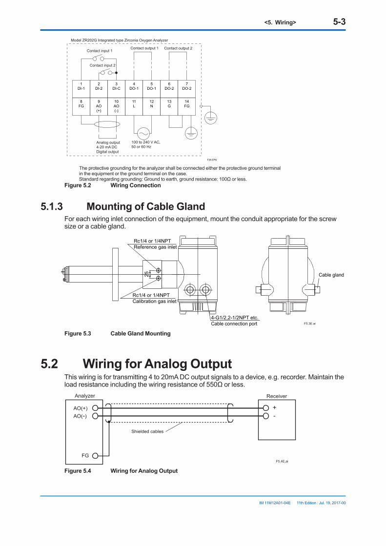
<5. Wiring> 5-3
IM 11M12A01-04E 11th Edition : Jul. 19, 2017-00
1DI-1
2DI-2
3DI-C
4DO-1
5DO-1
6DO-2
7DO-2
8FG
9AO(+)
10AO(-)
11L
12N
13G
14FG
F28.EPS
Model ZR202G Integrated type Zirconia Oxygen Analyzer
Contact input 1Contact output 2Contact output 1
Analog output 4-20 mA DC
100 to 240 V AC, 50 or 60 Hz
Digital output
Contact input 2
The protective grounding for the analyzer shall be connected either the protective ground terminal in the equipment or the ground terminal on the case. Standard regarding grounding: Ground to earth, ground resistance: 100Ω or less.
Figure 5.2 Wiring Connection
5.1.3 Mounting of Cable GlandFor each wiring inlet connection of the equipment, mount the conduit appropriate for the screw size or a cable gland.
F5.3E.ai
25
4-G1/2,2-1/2NPT etc.Cable connection port
Cable gland
Rc1/4 or 1/4NPTReference gas inlet
Rc1/4 or 1/4NPTCalibration gas inlet
Figure 5.3 Cable Gland Mounting
5.2 Wiring for Analog OutputThis wiring is for transmitting 4 to 20mA DC output signals to a device, e.g. recorder. Maintain the load resistance including the wiring resistance of 550Ω or less.
+-
AO(+)AO(-)
FGF5.4E.ai
Shielded cables
Analyzer Receiver
Figure 5.4 Wiring for Analog Output

<5. Wiring> 5-4
IM 11M12A01-04E 11th Edition : Jul. 19, 2017-00
5.2.1 Cable SpecificationsUse a 2-core shielded cable for wiring.
5.2.2 Wiring Procedure(1) M4 screws are used for the terminals. Use crimp-on terminals appropriate for M4 terminal
screws for cable connections. Ensure that the cable shield is connected to the FG terminal of the equipment.
(2) Be sure to connect (+) and (-) polarities correctly.
CAUTION• Before opening the cover, loosen the lock screw. If the screw is not loosened first, the cover
will be improperly engaged to the body, and the terminal box will require replacement. When opening and closing the cover, remove any sand particles or dust to avoid gouging the thread.
• After screwing the cover on the equipment body, secure it with the lock screw.
5.3 Wiring Power and Ground TerminalsWiring for supplying power to the analyzer and grounding the equipment.
1 2 C DO DODIDI
1 2
L NFG + -AO
~
100~240VAC50/60Hz F5.5E.ai
Jumper plate
Grounding to the earth terminal on the equipment case
Equipment case
Lock washer
Crimp contact of the grounding line
Grounding terminal
Ground
FGG
Figure 5.5 Power and Grounding Wiring
5.3.1 Wiring for Power LineConnect the power wiring to the L and N terminals of the equipment. For a three-core cable, ground one core appropriately. Proceed as follows:
(1) Use a two-core or three-core cable.(2) M4 screws are used for the terminals. Use crimp-on terminals appropriate for M4 terminal
screws for cable connections.
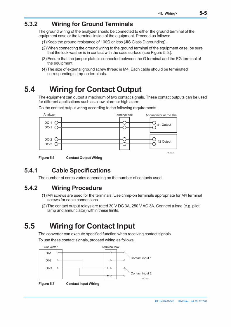
<5. Wiring> 5-5
IM 11M12A01-04E 11th Edition : Jul. 19, 2017-00
5.3.2 Wiring for Ground TerminalsThe ground wiring of the analyzer should be connected to either the ground terminal of the equipment case or the terminal inside of the equipment. Proceed as follows:
(1) Keep the ground resistance of 100Ω or less (JIS Class D grounding).(2) When connecting the ground wiring to the ground terminal of the equipment case, be sure
that the lock washer is in contact with the case surface (see Figure 5.5.).(3) Ensure that the jumper plate is connected between the G terminal and the FG terminal of
the equipment.(4) The size of external ground screw thread is M4. Each cable should be terminated
corresponding crimp-on terminals.
5.4 Wiring for Contact OutputThe equipment can output a maximum of two contact signals. These contact outputs can be used for different applications such as a low alarm or high alarm.Do the contact output wiring according to the following requirements.
DO-1DO-1
DO-2DO-2
F5.6E.ai
#2 Output
Analyzer Terminal box Annunciator or the like
#1 Output
Figure 5.6 Contact Output Wiring
5.4.1 Cable SpecificationsThe number of cores varies depending on the number of contacts used.
5.4.2 Wiring Procedure(1) M4 screws are used for the terminals. Use crimp-on terminals appropriate for M4 terminal
screws for cable connections.(2) The contact output relays are rated 30 V DC 3A, 250 V AC 3A. Connect a load (e.g. pilot
lamp and annunciator) within these limits.
5.5 Wiring for Contact InputThe converter can execute specified function when receiving contact signals.To use these contact signals, proceed wiring as follows:
Converter Terminal box
DI-1
DI-C
DI-2Contact input 1
Contact input 2F5.7E.ai
Figure 5.7 Contact Input Wiring

<5. Wiring> 5-6
IM 11M12A01-04E 11th Edition : Jul. 19, 2017-00
5.5.1 Cable SpecificationsUse a 2-core or 3-core cable for this wiring. Depending on the number of input(s), determine which cable to use.
5.5.2 Wiring Procedure(1) M4 screws are used for the terminal of the converter. Each cable should be equipped with
the corresponding crimp contact.(2) The ON/OFF level of this contact input is identified by the resistance. Connect a contact
input that satisfies the descriptions in Table 5.2.
Table 5.2 Identification of Contact Input ON/OFF
Closed OpenResistance 200 Ω or less 100 kΩ or more
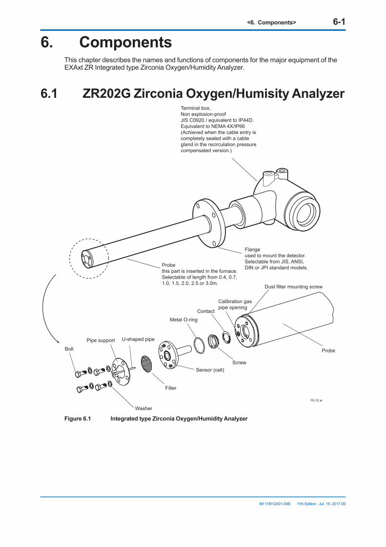
<6. Components> 6-1
IM 11M12A01-04E 11th Edition : Jul. 19, 2017-00
6. ComponentsThis chapter describes the names and functions of components for the major equipment of the EXAxt ZR Integrated type Zirconia Oxygen/Humidity Analyzer.
6.1 ZR202G Zirconia Oxygen/Humisity AnalyzerTerminal box, Non explosion-proof JIS C0920 / equivalent to IP44D.Equivalent to NEMA 4X/IP66(Achieved when the cable entry is completely sealed with a cable gland in the recirculation pressure compensated version.)
Probethis part is inserted in the furnace. Selectable of length from 0.4, 0.7, 1.0, 1.5, 2.0, 2.5 or 3.0m.
Flangeused to mount the detector. Selectable from JIS, ANSI, DIN or JPI standard models.
F6.1E.ai
Bolt
Washer
Pipe support U-shaped pipe
Metal O-ring
Dust filter mounting screw
Sensor (cell)
Contact
Screw
Probe
Calibration gas pipe opening
Filter
Figure 6.1 Integrated type Zirconia Oxygen/Humidity Analyzer

<6. Components> 6-2
IM 11M12A01-04E 11th Edition : Jul. 19, 2017-00
6.2 ZA8F Flow Setting Unit, ZR20H Automatic Calibration Unit
Reference gas flow setting valve
Span gas flow setting valve
Zero gas flow setting valve
Flowmeter forreference gas
Flowmeter forcalibration gas F6-4E.ai
Figure 6.2 ZA8F Flow Setting Unit
ZERO INREF INSPAN IN ZERO INREF INSPAN IN
F6.3E.ai
Flowmeter for Span gas
Flowmeter for Span gas
Flowmeter for Reference gas
Flowmeter for Reference gas
Flowmeter for Zero gas
Flowmeter for Zero gas
Horizontal mounting Vertical mounting
Span gas flow setting valve
Span gas flow setting valve
Reference gasflow setting valve
Reference gasflow setting valve
Zero gas flow setting valve
Span gas flow setting valve
Figure 6.3 ZR20H Automatic Calibration Unit
<7. Startup> 7-1
IM 11M12A01-04E 11th Edition : Jul. 19, 2017-00
7. StartupThe following describes the minimum operating requirements — from supplying power to the converter to analog output confirmation to manual calibration.In the figure listed in this manual, the example of the oxygen analyzer is shown mainly. In the case of the humidity analyzer, unit indication may be different. Please read it appropriately.
F7.0E.ai
Place in normal operation
Check piping and wiring connections
Set up valves
Supply power
Confirm converter type setting
Select gas to be measured
Set output ranges
Check current loop
Check contact action
Calibrate analyzer
Set detailed data
Figure 7.1 Startup Procedure
For system tuning by HART communication, refer to the IM 11M12A01-51E ‘’HART Communication Protocol’’.
7.1 Checking Piping and Wiring ConnectionsRefer to Chapters 4 and 5, earlier in this manual, for piping and wiring confirmations.
7.2 Valve SetupSet up valves and associated components used in the analyzer system in the following procedures:
(1) If a stop valve is used in the detector’s calibration gas inlet, fully close this valve.
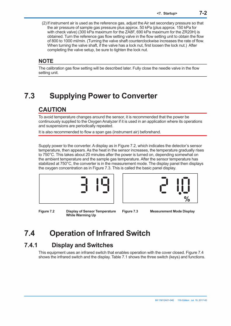
<7. Startup> 7-2
IM 11M12A01-04E 11th Edition : Jul. 19, 2017-00
(2) If instrument air is used as the reference gas, adjust the Air set secondary pressure so that the air pressure of sample gas pressure plus approx. 50 kPa (plus approx. 150 kPa for with check valve) (300 kPa maximum for the ZA8F, 690 kPa maximum for the ZR20H) is obtained. Turn the reference gas flow setting valve in the flow setting unit to obtain the flow of 800 to 1000 ml/min. (Turning the valve shaft counterclockwise increases the rate of flow. When turning the valve shaft, if the valve has a lock nut, first loosen the lock nut.) After completing the valve setup, be sure to tighten the lock nut.
NOTEThe calibration gas flow setting will be described later. Fully close the needle valve in the flow setting unit.
7.3 Supplying Power to ConverterCAUTIONTo avoid temperature changes around the sensor, it is recommended that the power be continuously supplied to the Oxygen Analyzer if it is used in an application where its operations and suspensions are periodically repeated. It is also recommended to flow a span gas (instrument air) beforehand.
Supply power to the converter. A display as in Figure 7.2, which indicates the detector’s sensor temperature, then appears. As the heat in the sensor increases, the temperature gradually rises to 750°C. This takes about 20 minutes after the power is turned on, depending somewhat on the ambient temperature and the sample gas temperature. After the sensor temperature has stabilized at 750°C, the converter is in the measurement mode. The display panel then displays the oxygen concentration as in Figure 7.3. This is called the basic panel display.
%
Figure 7.2 Display of Sensor Temperature Figure 7.3 Measurement Mode Display While Warming Up
7.4 Operation of Infrared Switch7.4.1 Display and Switches
This equipment uses an infrared switch that enables operation with the cover closed. Figure 7.4 shows the infrared switch and the display. Table 7.1 shows the three switch (keys) and functions.

<7. Startup> 7-3
IM 11M12A01-04E 11th Edition : Jul. 19, 2017-00
2: Infrared switch
4: Decimal point
1: Data display area
3: Engineering-unit display area
> > ENT
µMmNkga lbb l %scftm3 /d /s /h /m
F7.3E.ai
Figure 7.4 Infrared switch and the display
1. Data display area: Displays the oxygen concentration, humidity, set values, alarm numbers, and error numbers.
2. Infrared switch: Three switches perform data setting operations.3. Engineering-unit display area: the percent sign appears when the oxygen concentration or
humidity is displayed.4. Decimal point: A decimal point is displayed.
Table 7.1 Switch and Function
Switch Function> 1. Moves the position of the digit to the right. If you continuously touch the key, the position
of the digit will move continuously to the right, finally returning to the leftmost position after reaching the rightmost position of the digit.
2. Selects Yes or No.3. When you touch this key together with the [ENT] key, the previous display then appears,
or the operation will be cancelled.^ Used to change values. If you continuously touch this key, the value of the digit will increase
continuously, e.g., from 1 to 2 to 3 (for numeric data), or from A to B to C (for alphabetic characters), and finally return to its original value.
ENT 1. Used to change the basic panel display to the parameter selection display.2. Used to enter data.3. Advances the operation.
The three infrared switches are activated by completely touching the glass surface of the switch. To touch any of the keys continuously, first touch the surface and then completely remove your finger from the surface. Then touch it again.Infrared switches consist of two elements: an infrared emitting element and an infrared acceptance element. Infrared light-waves from the element bounces on the operator’s finger and are reflected back to the acceptance element, thereby causing the infrared switch to turn on and off, depending on the strength of the reflected light-waves. From this operating principles, carefully observe the following:
CAUTION1. Be sure to put the equipment case cover back on. If this is not done, the infrared switch will
not reflect the infrared light-waves, and a “dSPErr” error will be issued. 2. Before placing the equipment in operation, be sure to wipe off any moisture or dust on
the glass surface if it is wet or dirty. Also make sure your fingers are clean and dry before touching the glass surface of the switch.
3. If the infrared switches are exposed to direct sunlight, they may not operate correctly. In such a case, change position of the display or install a sun cover.

<7. Startup> 7-4
IM 11M12A01-04E
7.4.2 Display ConfigurationThe parameter codes provided for the equipment are used to control the equipment display panels (see below). By selecting appropriate parameter codes, you can conduct calibration and set operation parameters. Figure 7.5 shows the configuration of display items. The parameter codes are listed in groups of seven; which are briefly described in Table 7.2.To enter parameters, you first need to enter the password, refer to See 7.4.3.Touch the [ >] key and [ ENT] key at same time to revert to the main screen.
F7.4E.aiGroup G setup display
Basic panel display
Password entry display
Group A setup display
Group B setup display
Group C setup display
Parameter code selection displayGroup D setup display
Group E setup display
Group F setup display
%
Figure 7.5 Display Configuration
Table 7.2 Display Functions
Display Function and item to be setBasic panel Displays the oxygen concentration in normal operation, or displays the detector
heater temperature while warming up. In case of humidity analyzer, displays the oxygen con. or moisture quantity, or mixture ratio in normal operation. If an error or alarm arises, the corresponding error or alarm number appears.
Password entry Enters the password for the parameter code selection display.Group A setup Displays detailed data, such as the cell voltage or temperature.Group B setup Sets and performs calibration.Group C setup Sets analog output.Group D setup Sets an alarm.Group E setup Sets the input and output contacts.Group F setup Selects the type of equipment and sets the parameters for computation.Group G setup Performs the current-loop or contact checks.
11th Edition : Jul. 19, 2017-00

<7. Startup> 7-5
IM 11M12A01-04E
7.4.3 Entering Parameter Code Selection DisplayThis section briefly describes the password entry procedure for entering the parameter code selection display. The password is 1102 - it cannot be changed to a different password.
Switch operation Display Description
> ∧ ENT 21.0% Warm-up is complete, and the basic panel is now displayed.
> ∧ ENT PASSno Continuously touch the [ENT] key for at least three seconds to display "PASSno."
> ∧ ENT 0000 Touch the [ENT] key again. This allows you to change the leftmostdigit that is flashing.
> ∧ ENT 1000 Set the password 1102. If you touch the [∧] key, the digit that is flashing will be 1.
> ∧ ENT 1000 Touch the [>] key to move the position of the digit that is flashing to the right one digit.
> ∧ ENT 1100 Touch the [∧] key to change the numeric value to 1.
> ∧ ENT 1100 Touch the [>] key again to move the position of the digit that is flashing to the right one more digit. Continuously touch the [>] key, and the position of the digit that is flashing will move continuously to the right.
> ∧ ENT 1102 Touch the [∧] key to change the numeric value to 2. Continuously touch [∧] key, and the numeric value increases continuously.
> ∧ ENT 1102 If you touch the [ENT] key, all the digits flash.
> ∧ ENT A01 Touch the [ENT] key again to display A01 on the parameter code selection display.
The symbol [ ] indicates that the key is being touched. Light characters indicate that the digits are flashing.
CAUTION• If no key is touched for at least 20 seconds during password entry, the current display will
automatically switch to the basic panel display.• If no key is touched for at least 10 minutes during parameter code selection, the current
display will automatically switch to the basic panel display.
11th Edition : Jul. 19, 2017-00
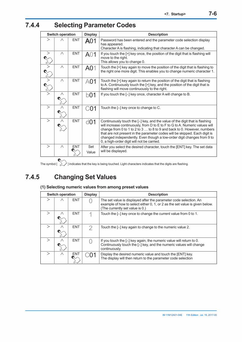
<7. Startup> 7-6
IM 11M12A01-04E
7.4.4 Selecting Parameter CodesSwitch operation Display Description> ∧ ENT A01 Password has been entered and the parameter code selection display
has appeared. Character A is flashing, indicating that character A can be changed.
> ∧ ENT A01 If you touch the [>] key once, the position of the digit that is flashing will move to the right. This allows you to change 0.
> ∧ ENT A01 Touch the [>] key again to move the position of the digit that is flashing to the right one more digit. This enables you to change numeric character 1.
> ∧ ENT A01 Touch the [>] key again to return the position of the digit that is flashing to A. Continuously touch the [>] key, and the position of the digit that is flashing will move continuously to the right.
> ∧ ENT b01 If you touch the [∧] key once, character A will change to B.
> ∧ ENT C01 Touch the [∧] key once to change to C.
> ∧ ENT d01 Continuously touch the [∧] key, and the value of the digit that is flashing will increase continuously, from D to E to F to G to A. Numeric values will change from 0 to 1 to 2 to 3 … to 8 to 9 and back to 0. However, numbers that are not present in the parameter codes will be skipped. Each digit is changed independently. Even though a low-order digit changes from 9 to 0, a high-order digit will not be carried.
> ∧ ENT Set Value
After you select the desired character, touch the [ENT] key. The set data will be displayed.
The symbol [ ] indicates that the key is being touched. Light characters indicates that the digits are flashing.
7.4.5 Changing Set Values(1) Selecting numeric values from among preset values
Switch operation Display Description> ∧ ENT 0 The set value is displayed after the parameter code selection. An
example of how to select either 0, 1, or 2 as the set value is given below.(The currently set value is 0.)
> ∧ ENT 1 Touch the [∧] key once to change the current value from 0 to 1.
> ∧ ENT 2 Touch the [∧] key again to change to the numeric value 2.
> ∧ ENT 0 If you touch the [∧] key again, the numeric value will return to 0.Continuously touch the [∧] key, and the numeric values will change continuously.
> ∧ ENT C01 Display the desired numeric value and touch the [ENT] key.The display will then return to the parameter code selection
11th Edition : Jul. 19, 2017-00

<7. Startup> 7-7
IM 11M12A01-04E
(2) Entering numeric values such as oxygen concentration values and factorsSwitch operation Display Description> ∧ ENT 00.0 The set value is displayed after the parameter code selection.
An example of entering "9.8" is given below. (The currently set value is 0.0)
> ∧ ENT 00.0 Touch the [>] key to move the position of the digit that is flashing to the digit to be changed.Continuously touch the [>] key, and the position of the digit that is flashing will move continuously to the right.
> ∧ ENT 09.0 Touch the [∧] key to set the numeric value 9.Continuously touch the [∧] key, and the numeric value will change in sequence from 0 to 1 to 2 to 3 … to 8 to 9 and back to 0.
> ∧ ENT 09.0 Touch the [>] key to move the position of the digit that is flashing to the right.
> ∧ ENT 09.8 Touch the [∧] key to set the numeric value 8.
> ∧ ENT 09.8 Where the correct numeric value is displayed, touch the [ENT] key.
> ∧ ENT 09.8 If you touch the [ENT] key again, the flashing stops and the current set value will be in effect.
> ∧ ENT C11 Touch the [ENT] key once again to return to the parameter code selection display.
(3) If invalid numeric values are entered.Switch operation Display Description> ∧ ENT 98.0 If an invalid numeric value (beyond the input range specified) is entered,
"Err" will appear for two seconds after touching the [ENT] key.
> ∧ ENT Err> ∧ ENT 00.0 "Err" appears for two seconds, and the display returns to the first set
value.Re-enter the numeric value.
11th Edition : Jul. 19, 2017-00
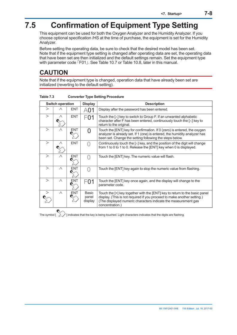
<7. Startup> 7-8
IM 11M12A01-04E
7.5 Confirmation of Equipment Type SettingThis equipment can be used for both the Oxygen Analyzer and the Humidity Analyzer. If you choose optional specification /HS at the time of purchase, the equipment is set for the Humidity Analyzer. Before setting the operating data, be sure to check that the desired model has been set. Note that if the equipment type setting is changed after operating data are set, the operating data that have been set are then initialized and the default settings remain. Set the equipment type with parameter code 「F01」. See Table 10.7 or Table 10.8, later in this manual.
CAUTIONNote that if the equipment type is changed, operation data that have already been set are initialized (reverting to the default setting).
Table 7.3 Converter Type Setting Procedure
Switch operation Display Description> ∧ ENT A01 Display after the password has been entered.
> ∧ ENT F01 Touch the [∧] key to switch to Group F. If an unwanted alphabetic character after F has been entered, continuously touch the [∧] key to return to the original.
> ∧ ENT 0 Touch the [ENT] key for confirmation. If 0 (zero) is entered, the oxygen analyzer is already set. If 1 (one) is entered, the humidity analyzer has been set. Change the setting following the steps below.
> ∧ ENT 0 Continuously touch the [∧] key, and the position of the digit will change from 1 to 0 to 1 to 0. Release the [ENT] key when 0 is displayed.
> ∧ ENT 0 Touch the [ENT] key. The numeric value will flash.
> ∧ ENT 0 Touch the [ENT] key again to stop the numeric value from flashing.
> ∧ ENT F01 Touch the [ENT] key once again, and the display will change to the parameter code.
> ∧ ENT Basic panel
display
Touch the [>] key together with the [ENT] key to return to the basic panel display. (This is not required if you proceed to make another setting.) (The displayed numeric characters indicate the measurement gas concentration.)
The symbol [ ] indicates that the key is being touched. Light characters indicates that the digits are flashing.
11th Edition : Jul. 19, 2017-00
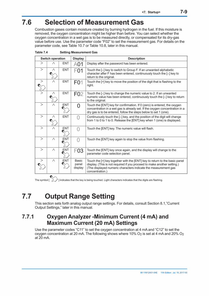
<7. Startup> 7-9
IM 11M12A01-04E
7.6 Selection of Measurement GasCombustion gases contain moisture created by burning hydrogen in the fuel. If this moisture is removed, the oxygen concentration might be higher than before. You can select whether the oxygen concentration in a wet gas is to be measured directly, or compensated for its dry-gas value before use. Use the parameter code “F02” to set the measurement gas. For details on the parameter code, see Table 10.7 or Table 10.8, later in this manual.
Table 7.4 Setting Measurement Gas
Switch operation Display Description> ∧ ENT A01 Display after the password has been entered.
> ∧ ENT F01 Touch the [∧] key to switch to Group F. If an unwanted alphabetic character after F has been entered, continuously touch the [∧] key to return to the original.
> ∧ ENT F01 Touch the [>] key to move the position of the digit that is flashing to the right.
> ∧ ENT F02 Touch the [∧] key to change the numeric value to 2. If an unwanted numeric value has been entered, continuously touch the [∧] key to return to the original.
> ∧ ENT 0 Touch the [ENT] key for confirmation. If 0 (zero) is entered, the oxygen concentration in a wet gas is already set. If the oxygen concentration in a dry gas is to be entered, follow the steps below to set 1 (one).
> ∧ ENT 0 Continuously touch the [∧] key, and the position of the digit will change from 1 to 0 to 1 to 0. Release the [ENT] key when 1 (one) is displayed.
> ∧ ENT 0 Touch the [ENT] key. The numeric value will flash.
> ∧ ENT 0 Touch the [ENT] key again to stop the value from flashing.
> ∧ ENT F03 Touch the [ENT] key once again, and the display will change to the parameter code selection panel.
> ∧ ENT Basic panel
display
Touch the [>] key together with the [ENT] key to return to the basic panel display. (This is not required if you proceed to make another setting.) (The displayed numeric characters indicate the measurement gas concentration.)
The symbol [ ] indicates that the key is being touched. Light characters indicates that the digits are flashing.
7.7 Output Range SettingThis section sets forth analog output range settings. For details, consult Section 8.1,”Current Output Settings,” later in this manual.
7.7.1 Oxygen Analyzer -Minimum Current (4 mA) and Maximum Current (20 mA) Settings
Use the parameter codes “C11” to set the oxygen concentration at 4 mA and “C12” to set the oxygen concentration at 20 mA. The following shows where 10% O2 is set at 4 mA and 20% O2 at 20 mA.
11th Edition : Jul. 19, 2017-00

<7. Startup> 7-10
IM 11M12A01-04E
Table 7.5 Minimum and Maximum Value Setting Procedure
Switch operation Display Description> ∧ ENT A01 Display after the password has been entered.
> ∧ ENT C01 Set the oxygen concentration at 4 mA. Change the parameter code to C11. Touch the [∧] key to switch to Group C.
> ∧ ENT C01 Touch the [>] key to move the position of the digit that is flashing to the right.
> ∧ ENT C11 Touch the [∧] key to enter the numeric value 1.
> ∧ ENT 000 Touch the [ENT] key to display the current set value (0% O2 has been set).
> ∧ ENT 000 Touch the [>] key to move the position of the digit that is flashing to the right.
> ∧ ENT 010 Touch the [∧] key to change the numeric value to 1.
> ∧ ENT 010 If you touch the [ENT] key, all the digits flash.
> ∧ ENT 010 Touch the [ENT] key again to stop the flashing.
> ∧ ENT C11 Touch the [ENT] key once again, and the display will switch to the parameter code selection display.
> ∧ ENT C11 Set the oxygen concentration at 20 mA. Touch the [>] key to move the position of the digit that is flashing to the right.
> ∧ ENT C12 Touch the [∧] key to enter the numeric value 2.
> ∧ ENT 025 Touch the [ENT] key to display the current set value.
> ∧ ENT 025 Touch the [>] key to move the position of the digit that is flashing to the right.
> ∧ ENT 020 Touch the [∧] key to change the numeric value to 0. The numeric value will change from 5 to 6 ... to 9 and back to 0.
> ∧ ENT 020 If you touch the [ENT] key, all the digits flash.
> ∧ ENT 020 Touch the [ENT] key again to stop the flashing.
> ∧ ENT C12 Touch the [ENT] key once again to switch to the parameter code selection display.
> ∧ ENT Basic panel
display
Touch the [>] key together with the [ENT] key to return to the basic panel display. (This is not required if you proceed to make another setting.)(The displayed numeric characters indicate the measurement gas concentration.)
The symbol [ ] indicates that the key is being touched. Light characters indicates that the digits are flashing.
11th Edition : Jul. 19, 2017-00
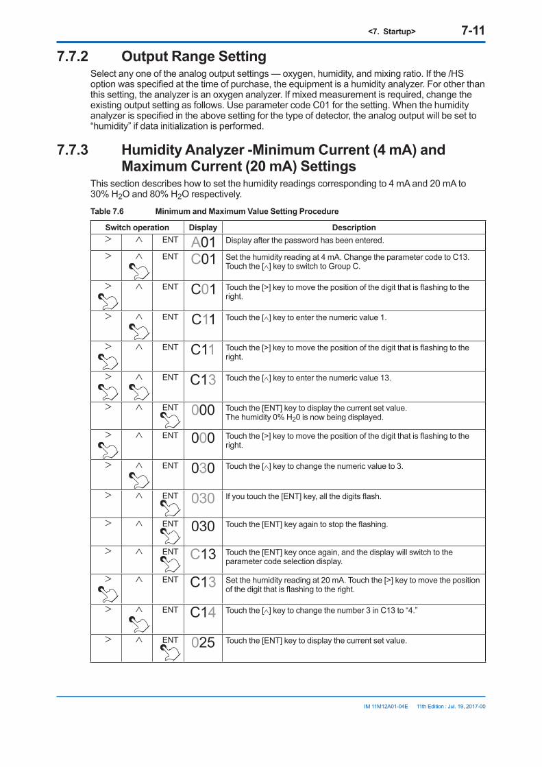
<7. Startup> 7-11
IM 11M12A01-04E
7.7.2 Output Range SettingSelect any one of the analog output settings — oxygen, humidity, and mixing ratio. If the /HS option was specified at the time of purchase, the equipment is a humidity analyzer. For other than this setting, the analyzer is an oxygen analyzer. If mixed measurement is required, change the existing output setting as follows. Use parameter code C01 for the setting. When the humidity analyzer is specified in the above setting for the type of detector, the analog output will be set to “humidity” if data initialization is performed.
7.7.3 Humidity Analyzer -Minimum Current (4 mA) and Maximum Current (20 mA) Settings
This section describes how to set the humidity readings corresponding to 4 mA and 20 mA to 30% H2O and 80% H2O respectively.
Table 7.6 Minimum and Maximum Value Setting Procedure
Switch operation Display Description> ∧ ENT A01 Display after the password has been entered.
> ∧ ENT C01 Set the humidity reading at 4 mA. Change the parameter code to C13. Touch the [∧] key to switch to Group C.
> ∧ ENT C01 Touch the [>] key to move the position of the digit that is flashing to the right.
> ∧ ENT C11 Touch the [∧] key to enter the numeric value 1.
> ∧ ENT C11 Touch the [>] key to move the position of the digit that is flashing to the right.
> ∧ ENT C13 Touch the [∧] key to enter the numeric value 13.
> ∧ ENT 000 Touch the [ENT] key to display the current set value.The humidity 0% H20 is now being displayed.
> ∧ ENT 000 Touch the [>] key to move the position of the digit that is flashing to the right.
> ∧ ENT 030 Touch the [∧] key to change the numeric value to 3.
> ∧ ENT 030 If you touch the [ENT] key, all the digits flash.
> ∧ ENT 030 Touch the [ENT] key again to stop the flashing.
> ∧ ENT C13 Touch the [ENT] key once again, and the display will switch to the parameter code selection display.
> ∧ ENT C13 Set the humidity reading at 20 mA. Touch the [>] key to move the position of the digit that is flashing to the right.
> ∧ ENT C14 Touch the [∧] key to change the number 3 in C13 to “4.”
> ∧ ENT 025 Touch the [ENT] key to display the current set value.
11th Edition : Jul. 19, 2017-00

<7. Startup> 7-12
IM 11M12A01-04E
Switch operation Display Description> ∧ ENT 025 Touch the [>] key to move the position of the digit that is flashing to the
right.
> ∧ ENT 085 Touch the [∧] key to change the number 2 in C25 to “8.”
> ∧ ENT 085 Touch the [>] key to move the position of the digit that is flashing to the right.
> ∧ ENT 080 Touch the [∧] key to change the number 5 in C85 to “0.” The number changes from 5 to 6 . to 9 to 0.
> ∧ ENT 080 If you touch the [ENT] key, all the digits flash.
> ∧ ENT 080 Touch the [ENT] key again to stop the flashing.
> ∧ ENT C14 Touch the [ENT] key once again to switch to the parameter code selection display.
> ∧ ENT Basic panel
display
Touch the [>] key together with the [ENT] key to return to the basic panel display. (This is not required if you proceed to make another setting.)(The displayed numeric characters indicate the measurement gas concentration.)
The symbol [ ] indicates that the key is being touched. Light characters indicates that the digits are flashing.
7.8 Setting Display Item7.8.1 Oxygen Analyzer - Setting Display Item
Display items are defined as items displayed on the basic panel display. Parameter code “A00” or “F08” is used to set the display items as shown in Table 7.7. The oxygen concentration is set at the factory before shipment. In addition, if the data initialization is performed, the oxygen concentration will be set.
Table 7.7 Display Item
Values set with A00 or F08 Items displayed on the basic panel display0 Indicates the oxygen concentration.
1 or 2 For humidity analyzers only. (if 1 or 2 is set for the oxygen analyzer, "0.0" is only displayed on the basic panel display.)
3 Displays an item for the current output.If the output damping has been set for the current output, values involving the output damping are displayed.
CAUTIONIf you set “3” in the parameter code “A00” or “F08”, be sure to select “Oxygen Concentration” in the following mA output setting (see Section 8.1, “Current Output Setting”).
11th Edition : Jul. 19, 2017-00

<7. Startup> 7-13
IM 11M12A01-04E
7.8.2 Humidity Analyzer - Setting Display ItemDisplay items are those items that are displayed on the basic panel display. Parameter code A00 or F08 is used to set the display items as shown in the table below. If the humidity analyzer /HS option was specified at the time of purchase, the equipment is a humidity analyzer. For other than the above, the equipment is set to oxygen concentration at the factory before shipment. If mix ratio is to be measured, change the existing setting as follows.Additionally, when humidity analyzer is selected in the Detector Type Setting in the previous section, the display item will be humidity if data initialization is performed.
Table 7.8 Display Item
Values set with A00 or F08 Items displayed on the basic panel display0 Indicates the oxygen concentration.1 Indicates the humidity.2 Indicates the mix ratio.3 Displays an item for the current output.
If the output damping has been set for the current output, values involving the output damping are displayed.
7.9 Checking Current LoopThe set current can be output as an analog output. This enables the checking of wiring between the converter and the receiving instrument. Current loop checking is performed using parameter code “G01”.
Table 7.9 Checking Current Loop
Switch operation Display Description> ∧ ENT A01 Display after the password has been entered.
> ∧ ENT G01 Touch the [∧] key to switch to Group G.
> ∧ ENT 00.0 Touch the [ENT] key. The output current remains preset with the output-hold feature (Section 2.3).
> ∧ ENT 10.0 Touch the [∧] key to set the numeric value 1 (to set a 10-mA output).
> ∧ ENT 10.0 Touch the [ENT] key to have all the digits flash.
> ∧ ENT 10.0 Touch the [ENT] key again to stop the flashing.A 10-mA output is then issued.
> ∧ ENT G01 Touch the [ENT] key once again to switch to the parameter code selection display.At that point, the output current returns to the normal value.
> ∧ ENT Basic panel
display
Touch the [>] key together with the [ENT] key to return to the basic panel display.
The symbol [ ] indicates that the key is being touched. Light characters indicates that the digits are flashing.
11th Edition : Jul. 19, 2017-00

<7. Startup> 7-14
IM 11M12A01-04E
7.10 Checking Contact I/OConduct a contact input and output check as well as an operation check of the solenoid valves for the optional automatic calibration unit.
Table 7.10 Parameter Codes for Checking Contact I/O
Check item Parameter code Set value and contact actionContact output 1 G11 0 Open
1 ClosedContact output 2 G12 0 Open
1 ClosedAutomatic calibration solenoid valve (zero gas)
G15 0 Off1 On
Automatic calibration solenoid valve (span gas)
G16 0 Off1 On
Contact input 1 G21 0 Open1 Closed
Contact input 2 G22 0 Open1 Closed
7.10.1 Contact Output CheckFollow Table 7.11 to check the contact output. The table uses an example with contact output 1.
Table 7.11 Checking Contact Output
Switch operation Display Description> ∧ ENT A01 Display after the password has been entered.
> ∧ ENT G01 Touch the [∧] key to switch to Group G.
> ∧ ENT G01 Touch the [>] key to move the position of the digit that is flashing to the right one digit.
> ∧ ENT G11 Touch the [∧] key to enter 1.
> ∧ ENT 0 Touch the [ENT] key to have 0 (zero) flash. The contact is then open.
> ∧ ENT 1 Touch the [∧] key to set 1 (one).
> ∧ ENT 1 Touch the [ENT] key. The flashing continues.
> ∧ ENT 1 Touch the [ENT] key again to stop the flashing, and the contact will be closed.
> ∧ ENT G11 Touch the [ENT] key once again to switch to the parameter code selection display.The contact then returns to the original state.
> ∧ ENT Basic panel
display
Touch the [>] key together with the [ENT] key to return to the basic panel display. (This is not required if you proceed to make another setting.)(The displayed numeric characters indicate the measurement gas concentration.)
The symbol [ ] indicates that the key is being touched. Light characters indicates that the digits are flashing.
11th Edition : Jul. 19, 2017-00

<7. Startup> 7-15
IM 11M12A01-04E
CAUTIONIf you conduct an open-close check for the contact output 2, Error 1 (cell voltage failure) or Error 2 (heater temperature abnormal) will occur. This is because the built-in heater power of the detector, which is connected to contact output 2, is turned off during the above check. So, if the above error occurs, reset the equipment or turn the power off and then back on to restart (refer to Section 10.4, “Reset,” later in this manual).
7.10.2 Checking Calibration Contact OutputThe calibration contacts are used for the solenoid valve drive signals for the Automatic Calibration Unit. This output signal enables you to check the equipment operation. Check the flowmeter gas flow for that operation. Follow the steps in Table 7.12. The table uses an example with a zero gas solenoid valve.
Table 7.12 Checking Calibration Contact Output
Switch operation Display Description> ∧ ENT A01 Display after the password has been entered.
> ∧ ENT G01 Touch the [∧] key to switch to Group G.
> ∧ ENT G01 Touch the [>] key to move the position of the digit that is flashing to the right one digit.
> ∧ ENT G11 Touch the [∧] key to enter 1.
> ∧ ENT G11 Touch the [>] key to move the position of the digit that is flashing to the right one digit.
> ∧ ENT G15 Touch the [∧] key to enter 5.
> ∧ ENT 0 Touch the [ENT] key to have 0 flash.The solenoid valve remains closed.
> ∧ ENT 1 Touch the [∧] key to enter 1.
> ∧ ENT 1 Touch the [ENT] key. The flashing continues.
> ∧ ENT 1 Touch the [ENT] key again to stop the flashing, and the solenoid valve will be open to let the calibration gas flow.
> ∧ ENT G15 Touch the [ENT] key once again to switch to the parameter code selection display.The solenoid valve will then be closed.
> ∧ ENT Basic panel
display
Touch the [>] key together with the [ENT] key to return to the basic panel display.(This is not required if you proceed to make another setting.)(The displayed numeric characters indicate the measurement gas concentration.)
The symbol [ ] indicates that the key is being touched. Light characters indicates that the digits are flashing.
11th Edition : Jul. 19, 2017-00
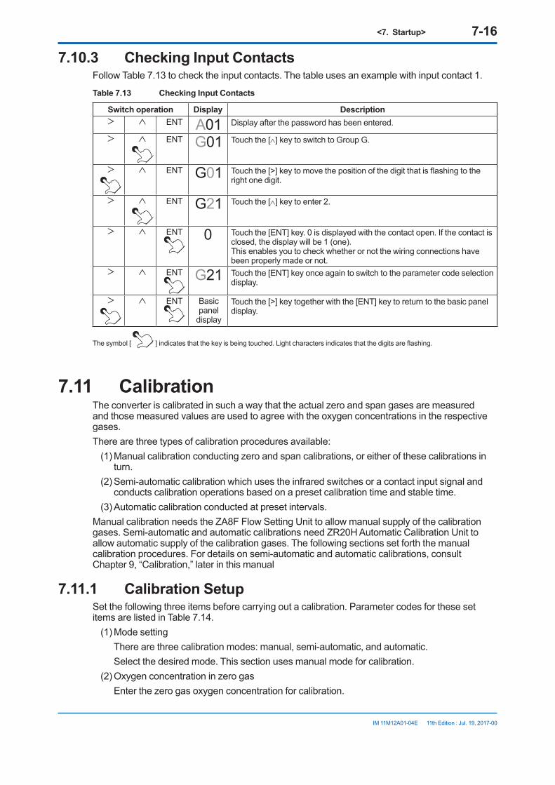
<7. Startup> 7-16
IM 11M12A01-04E
7.10.3 Checking Input ContactsFollow Table 7.13 to check the input contacts. The table uses an example with input contact 1.
Table 7.13 Checking Input Contacts
Switch operation Display Description> ∧ ENT A01 Display after the password has been entered.
> ∧ ENT G01 Touch the [∧] key to switch to Group G.
> ∧ ENT G01 Touch the [>] key to move the position of the digit that is flashing to the right one digit.
> ∧ ENT G21 Touch the [∧] key to enter 2.
> ∧ ENT 0 Touch the [ENT] key. 0 is displayed with the contact open. If the contact is closed, the display will be 1 (one).This enables you to check whether or not the wiring connections have been properly made or not.
> ∧ ENT G21 Touch the [ENT] key once again to switch to the parameter code selection display.
> ∧ ENT Basic panel
display
Touch the [>] key together with the [ENT] key to return to the basic panel display.
The symbol [ ] indicates that the key is being touched. Light characters indicates that the digits are flashing.
7.11 CalibrationThe converter is calibrated in such a way that the actual zero and span gases are measured and those measured values are used to agree with the oxygen concentrations in the respective gases.There are three types of calibration procedures available:
(1) Manual calibration conducting zero and span calibrations, or either of these calibrations in turn.
(2) Semi-automatic calibration which uses the infrared switches or a contact input signal and conducts calibration operations based on a preset calibration time and stable time.
(3) Automatic calibration conducted at preset intervals.Manual calibration needs the ZA8F Flow Setting Unit to allow manual supply of the calibration gases. Semi-automatic and automatic calibrations need ZR20H Automatic Calibration Unit to allow automatic supply of the calibration gases. The following sections set forth the manual calibration procedures. For details on semi-automatic and automatic calibrations, consult Chapter 9, “Calibration,” later in this manual
7.11.1 Calibration SetupSet the following three items before carrying out a calibration. Parameter codes for these set items are listed in Table 7.14.
(1) Mode setting There are three calibration modes: manual, semi-automatic, and automatic. Select the desired mode. This section uses manual mode for calibration.(2) Oxygen concentration in zero gas Enter the zero gas oxygen concentration for calibration.
11th Edition : Jul. 19, 2017-00
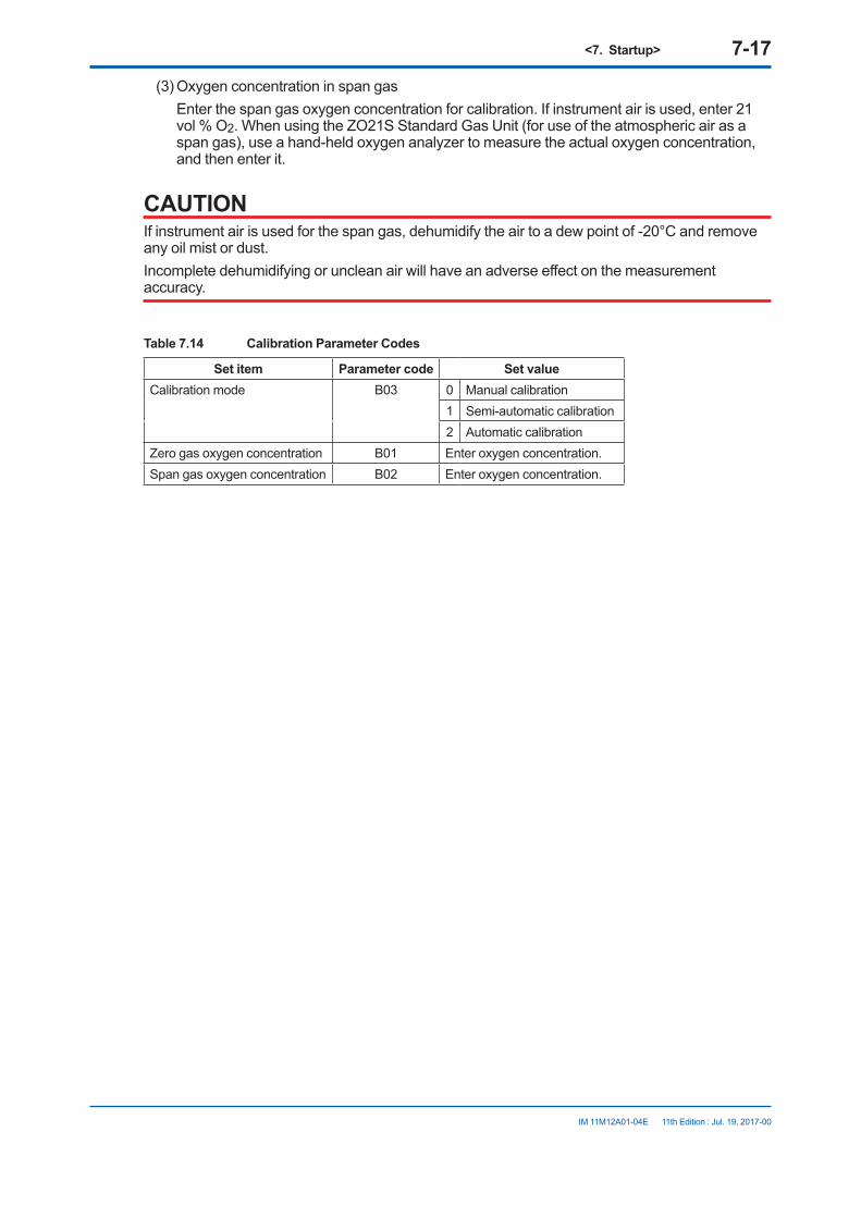
<7. Startup> 7-17
IM 11M12A01-04E
(3) Oxygen concentration in span gas Enter the span gas oxygen concentration for calibration. If instrument air is used, enter 21
vol % O2. When using the ZO21S Standard Gas Unit (for use of the atmospheric air as a span gas), use a hand-held oxygen analyzer to measure the actual oxygen concentration, and then enter it.
CAUTIONIf instrument air is used for the span gas, dehumidify the air to a dew point of -20°C and remove any oil mist or dust.Incomplete dehumidifying or unclean air will have an adverse effect on the measurement accuracy.
Table 7.14 Calibration Parameter Codes
Set item Parameter code Set valueCalibration mode B03 0 Manual calibration
1 Semi-automatic calibration2 Automatic calibration
Zero gas oxygen concentration B01 Enter oxygen concentration.Span gas oxygen concentration B02 Enter oxygen concentration.
11th Edition : Jul. 19, 2017-00

<7. Startup> 7-18
IM 11M12A01-04E
Table 7.15 Calibration Setup Procedure
Switch operation Display Description> ∧ ENT A01 Display after the password has been entered.
> ∧ ENT b01 Set the zero gas concentration. Switch the parameter code to B01.Here, set 0.98%.
> ∧ ENT 001.00 % Touch the [ENT] key to display the currently set value.
> ∧ ENT 001.00 % Touch the [>] key to move the position of the digit that is flashing to 1.
> ∧ ENT 000.00 % Touch the [∧] key to change to 0.
> ∧ ENT 000.00 % Touch the [>] key to move the position of the digit that is flashing to the right one digit.
> ∧ ENT 000.90 % Touch the [∧] key to change the numeric value to 9.
> ∧ ENT 000.90 % Touch the [>] key to move the position of the digit that is flashing to the right one digit.
> ∧ ENT 000.98 % Touch the [∧] key to change the numeric value to 8.
> ∧ ENT 000.98 % Touch the [ENT] key to have all the digits flash.
> ∧ ENT 000.98 % Touch the [ENT] key again to stop the flashing.
> ∧ ENT b01 Touch the [ENT] key once again to switch to the parameter code selection display.
Set the span gas concentration by above procedure, set 21 %.> ∧ ENT b03 Next, set the calibration mode. Switch the parameter code to B03.
> ∧ ENT 0 Touch the [ENT] key to display the currently set value.If it is 0, you can leave it as is. If it is other than 0, change it to 0 (zero).
> ∧ ENT 0 Touch the [ENT] key. The numeric value will flash.
> ∧ ENT 0 Touch the [ENT] key again to stop the flashing.
> ∧ ENT b03 Touch the [ENT] key once again to switch to the parameter code selection display.
> ∧ ENT Basic panel display
Touch the [>] key together with the [ENT] key to return to the basic panel display. (This is not required if you proceed to make another setting.)(The displayed numeric characters indicate the measurement gas concentration.)
The symbol [ ] indicates that the key is being touched. Light characters indicates that the digits are flashing.
11th Edition : Jul. 19, 2017-00

<7. Startup> 7-19
IM 11M12A01-04E
7.11.2 Manual CalibrationThe following describes how to conduct a calibration.
n PreliminaryBefore conducting a manual calibration, be sure that the ZA8F Flow Setting Unit zero gas flow valve is fully closed. Open the zero gas cylinder pressure regulator so that the secondary pressure will be a sample gas plus approx. 50 kPa (or sample gas pressure plus approx. 150 kPa when a check valve is used, maximum pressure rating is 300 kPa).
n Calibration ImplementationThis manual assumes that the instrument air is the same as the reference gas used for the span gas. Follow the steps below to conduct manual calibration. When using the ZO21S Standard Gas Unit (for use of the atmospheric air as a span gas), use a hand-held oxygen analyzer to measure the actual oxygen concentration, and then enter it.
Table 7.16 Conducting Calibration
Switch operation Display Description> ∧ ENT A01 Display after the password has been entered.
> ∧ ENT b10 Switch the parameter code to B10.(The key operations for this procedure are omitted.)
> ∧ ENT CAL Touch the [ENT] key, and "CAL" will be displayed.To cancel the above, touch the [>] key and [ENT] key together to return to the B10 display.
> ∧ ENT CAL If you touch the [ENT] key again, "CAL" then flashes.To cancel the above, touch the [>] key and [ENT] key together, the display will return to the B10 display.
> ∧ ENT SPAn Y If you touch the [ENT] key again, "SPAn Y" appears (Y is flashing).If you omit the span calibration, touch the [>] key, and change "Y" to "N".If you touch the [ENT] key, the display then jumps to "ZEro Y."
> ∧ ENT 21.00 % Touch the [ENT] key to display the calibration gas value, in other words, the span gas concentration set in Section 7.10.1, "Calibration Setup."To cancel the above, touch the [>] key and [ENT] key together, then the display returns to "SPAn Y."
> ∧ ENT OPEn /20.84
If you touch the [ENT] key, "OPEn" and the currently measured value are displayed alternately. Open the Flow Setting Unit span gas flow valve and adjust the span gas flow to 600 ± 60 ml/min. To do this, loosen the valve lock nut and gently turn the valve control (shaft) counterclockwise.Check the calibration gas flowmeter for confirmation.If the automatic calibration unit is connected, open the span gas solenoid valve, and the measured value changes to the span gas value.When the display becomes stable, proceed to the next step.To cancel the above, touch the [>] key and [ENT] key together, then the display returns to "SPAn Y."
> ∧ ENT 20.84 % If you touch the [ENT] key, all the digits flash. At that point, no calibration is conducted yet.
> ∧ ENT ZEro Y If you touch the [ENT] key again, the flashing stops and "ZEro Y" appears.Close the span gas flow valve. Secure the span gas lock nut for leakage.If the automatic calibration unit is connected, close the span gas solenoid valve.If zero gas calibration is omitted, touch the [>] key to change "Y" to "N".Next, if you touch the [ENT] key, the display jumps to "CALEnd."
11th Edition : Jul. 19, 2017-00

<7. Startup> 7-20
IM 11M12A01-04E
Switch operation Display Description> ∧ ENT 0.98 % Touch the [ENT] key to display the calibration gas value.
This value must be the zero gas concentration set in Section 7.10.1, "Calibration Setup," earlier in this manual.To cancel the above, touch the [>] key and [ENT] key together, then the display returns to "ZEro Y."
> ∧ ENT OPEn/0.89
If you touch the [ENT] key, "OPEn" and the currently measured value are displayed alternately. Open the Flow Setting Unit zero gas flow valve and adjust the zero gas flow to 600 ± 60 ml/min. To do this, loosen the valve lock nut and gently turn the valve control (shaft) counterclockwise.Check the calibration gas flowmeter for confirmation. If the automatic calibration unit is connected, open the zero gas solenoid valve, and then the measured value changes to the zero gas value. When the display becomes stable, proceed to the next step.To cancel the above, touch the [>] key and [ENT] key together, then the display returns to "ZEro Y."
> ∧ ENT 0.89 % If you touch the [ENT] key, all the digits flash. At that point, no calibration is conducted yet.
> ∧ ENT CALEnd Touch the [ENT] key again to get the measured value to agree with the zero gas concentration. Close the zero gas flow valve.Secure the valve lock nut for leakage during measurement.If the automatic calibration unit is connected, close the span gas solenoid valve. "CALEnd" flashes during the output hold time. If "output hold" is specified in the Output Hold setting," it remains as an analog output (see Section 8.2).When the preset output hold time is up, the calibration is complete.
> ∧ ENT b10 The output hold time is set to 10 minutes at the factory.If you touch both the [>] key and [ENT] key at the same time during the preset Output Hold Time, the calibration is aborted and the parameter code selection display appears.
> ∧ ENT Basic panel display
If you touch the [>] key and [ENT] key together, then the basic panel display appears.
The above “display” is a result of switch operations.
The symbol [ ] indicates the keys are being touched, and the light characters indicate “flashing.”“/” indicates that the characters are displayed alternately.
11th Edition : Jul. 19, 2017-00

<8. Detailed Data Setting> 8-1
IM 11M12A01-04E 11th Edition : Jul. 19, 2017-00
8. Detailed Data Setting
8.1 Current Output Setting8.1.1 Oxygen Analyzer_Current Output Setting
This section describes setting of the analog output range. Table 8.1 shows parameter codes for the set items.
Table 8.1 Current Output Parameter Codes
Set item Parameter code Set valueAnalog output C01 0 Oxygen concentration
1 4 mA (fixed *1)2 4 mA (fixed *1)
Output mode C03 0 Linear1 Logarithm
Min. oxygen concentration C11 Oxygen concentration at 4 mAMax. oxygen concentration C12 Oxygen concentration at 20 mAOutput damping constant C30 0 to 255 seconds
*1: For the oxygen analyzer, set 0 (zero) only for parameter code C01. When it is set, the current output is 4-mA fixed regardless of the oxygen concentration.
8.1.2 Oxygen Analyzer_Analog Output SettingThis section describes how to set the analog output range.(1) To provide an oxygen concentration, use parameter code C11 to set the minimum
oxygen concentration at 4 mA, and use parameter code C12 to set the maximum oxygen concentration at 20 mA.
(2) To provide a humidity output, use parameter code C13 to set the minimum humidity at 4 mA, and use parameter code C14 to set the maximum humidity at 20 mA.
(3) To provide a mix ratio, use parameter code C15 to set the minimum mix ratio at 4 mA, and use parameter code C14 to set the maximum mixing ratio at 20 mA.
Refer to Table 8.2 for the parameter codes.
Table 8.2 Current Output Parameter Codes
Set item Parameter code Set valueAnalog output C01 0 Oxygen concentration
1 Humidity2 Mixing ratio
Output mode C03 0 Linear1 Logarithm
Min. oxygen concentration C11 Oxygen concentration reading corresponding to 4 mAMax. oxygen concentration C12 Oxygen concentration reading corresponding to 20 mAMin. humidity C13 Humidity reading corresponding to 4 mAMax. humidity C14 Humidity reading corresponding to 20 mAMin. mixing ratio C15 Mixing ratio at 4 mAMax. mixing ratio C16 Mixing ratio at 20 mAOutput damping constant C30 0 to 255 seconds

<8. Detailed Data Setting> 8-2
IM 11M12A01-04E 11th Edition : Jul. 19, 2017-00
NOTEWhen you select logarithmic mode in Section 8.1.3, “Output Mode,” later in this manual, the oxygen concentration, humidity reading, and mixing ratio remain constant at 0.1% O2, 0.1% H2O and 0.01 kg/kg respectively.
8.1.3 Setting Minimum Oxygen Concentration (at 4 mA) and Maximum Oxygen Concentration (at 20 mA)
Set the oxygen concentration values at 4 mA and 20 mA.The minimum concentration of oxygen for the minimum current (4 mA) is 0% O2 or 6% to 76% O2.The maximum concentration of oxygen for the maximum current (20 mA) ranges from 5% to 100% O2, and must be greater than 1.3 times the concentration of oxygen set for the minimum. If it does not fall within this input range setting, the setting will be invalid, and the previous set values will remain.
Setting example 1If the setting (for a 4 mA current) is 10% O2, you must set the oxygen concentration for the maximum (20 mA) point at 13% O2.
Setting example 2If the setting (for a 4 mA current) is 75% O2, you must set the oxygen concentration for the maximum (20 mA) point at 98% O2 (75 × 1.3). (Numbers after the decimal point are rounded up.)
CAUTIONWhen you select logarithmic mode, the minimum output remains constant at 0.1% O2, and the parameter “C11” display remains unchanged.
8.1.4 Minimum and Maximum Settings Corresponding to 4 mA and 20 mA
Set the output items for oxygen concentration reading, humidity reading and mixing ratio corresponding to 4 mA and 20 mA. When the oxygen concentration was selected with parameter code C01, use parameter codes C11 and C12 for the minimum and maximum settings; when the humidity setting was selected with parameter code C01, use parameter codes C13 and C14 for those settings; and when the mix ratio setting was selected with parameter code C01, use parameter codes C15 and C16 for those settings.
8.1.5 Input RangesThe range low and high values are restricted as follows:
l Oxygen Concentration setting rangeThe range min. O2 concentration value (corresponding to 4 mA output) can be set to either 0 vol%O2 or in the range of 6 to 76 vol%O2.The range max. O2 concentration value (corresponding to 20 mA output) can be set to any value in the range of 5 to 100 vol%O2, however the range max. setting must be at least 1.3 times the range min. setting.

<8. Detailed Data Setting> 8-3
IM 11M12A01-04E 11th Edition : Jul. 19, 2017-00
If you do not observe this restriction, the measurement will be invalid, and any previous valid value will be used. The gray area in figure represents the valid setting range.
Setting example 1If the range minimum (corresponding to 4 mA output) is set to 10 vol%O2 then range maximum (corresponding to 20 mA output) must be at least 13 vol%O2.
Setting example 2If the range minimum (corresponding to 4 mA output) is set to 75 vol%O2 then range maximum (corresponding to 20 mA output) must be at least 75x1.3=98 vol%O2 (rounding decimal part up).
5
15
25
35
45
55
65
75
85
95
5 15 25 35 45 55 65 75
Minimum oxygen concentration, vol%O2 (for a minimum current of 4 mA)Minimum-Maximum setting range of oxygen concentration
Max
imum
oxy
gen
conc
entra
tion,
vol
%O
2 (fo
r a m
axim
um c
urre
nt o
f 20
mA
)
Ranges over which oxygen concentrations can be set
Outside ranges
F8.0E.ai
Figure A
l Humidity (amount-of-moisture-content) setting rangeThe minimum humidity is set to 0% H2O or ranges from 26 to 100% H2O. The maximum humidity ranges from 25% to 100% H2O, and must be greater than 0.8 times plus 23 the humidity set for the minimum.
Setting example 1If the setting (for a 4 mA current) is 0% H2O, you must set the maximum (20 mA) point at more than 25% H2O.
Setting example 2If the setting (for a 4 mA current) is 26% H2O, you must set the maximum (20 mA) point at more than 44% H2O, (263 0.8 + 23% H2O). (Numbers after the decimal point are rounded up.)

<8. Detailed Data Setting> 8-4
IM 11M12A01-04E 11th Edition : Jul. 19, 2017-00
40
50
60
70
80
90
100
25 30 35 40 45 50 55 60 65 70 75 80 85 90 95 100
F8-2E.ai
Minimum humidity (for a 4-mA current), % H2O
Max
imum
hum
idity
(for
a 2
0-m
A cu
rren
t), %
H2O
Ranges over which oxygen concentrations can be set
Outside ranges
Figure B Max. and Min. Humidity Set Ranges
l “Mixing ratio” setting rangeThe minimum mixing ratio is set to 0 kg/kg or ranges from 0.201 to 0.625 kg/kg. The maximum “mixing ratio” setting ranges from 0.2 to 1.0 kg/kg, and must be greater than 1.3 times plus 0.187 the mixing ratio set for the minimum.
Setting example 1If the setting (for a 4 mA current) is 0 kg/kg, you must set the maximum (20 mA) point at more than 0.2 kg/kg.
Setting example 2If the setting (for a 4 mA current) is 0.201 kg/kg, you must set the maximum (20 mA) point at more than 0.449 kg/kg, (0.201 3 1.3 + 0.187 kg/kg). (Numbers after the decimal point are rounded up.)
0.9
0.85
0.8
0.75
0.7
0.65
0.6
0.55
0.5
0.45
0.40.201 0.25 0.3 0.35 0.4 0.45 0.5 0.55 0.6 0.65
Max
imum
mix
ing
ratio
, kg/
kg a
t 20
mA
Minimum mixing ratio, kg/kg at 4 mA
Ranges over which oxygen concentrations can be set
Outside ranges
1
0.95
F8-3E.ai
Figure C Max. and Min. Mixing Ratio Set Ranges

<8. Detailed Data Setting> 8-5
IM 11M12A01-04E 11th Edition : Jul. 19, 2017-00
8.1.6 Entering Output Damping ConstantsIf a measured value adversely affected by a rapid change in the sample gas oxygen concentration is used for the control means, frequent on-off actions of the output will result. To avoid this, the converter allows the setting of output damping constants ranging from 0 to 255 seconds.
8.1.7 Selection of Output ModeYou can select a linear or logarithmic output mode. The former provides linear characteristics between the analog output signal and measured value.
NOTEWhen you select logarithmic mode, the minimum output remains constant at 0.1% O2, and the humidity remains set to 0.1% H2O and mixing ratio is set to 0.01 kg/kg, regardless of the set values. Set value of C11 to C16 remains unchanged.
8.1.8 Default ValuesWhen the analyzer is delivered or data are initialized, the output current settings are by default as shown in Table 8.3.
Table 8.3 Output Current Default Values
Item Default settingMin. oxygen concentration 0% O2
Max. oxygen concentration 25% O2
Minimum humidity 0% H2OMaximum humidity 25% H2OMinimum ratio setting 0 kg/kgMaximum ratio setting 0.2 kg/kgOutput damping constant 0 (seconds)Output mode Linear
8.2 Output Hold SettingThe “output hold” functions retain an analog output signal at a preset value during the equipment’s warm-up time or calibration or if an error arises. Table 8.4 shows the analog outputs that can be retained and the individual states.
Table 8.4 Analog Output Hold Setting
Equipment status
Output holdvalues available
During warm-up
During maintenance
During calibration
Error occurrence
(*1)
4 mA O20 mA OWithout hold feature O O ORetains output from just before occurrence O O O
Set value (2.4 to 21.6 mA) O O O O
O: The output hold functions are available.*1: The output hold functions on error occurrence are unavailable when option code “/C2” or “/C3” (NAMER NE 43 compliant) is
specified.

<8. Detailed Data Setting> 8-6
IM 11M12A01-04E 11th Edition : Jul. 19, 2017-00
8.2.1 Definition of Equipment Status(1) During warm-up
“During warm-up” is the time required after applying power until the sensor temperature stabilizes at 750°C, and the equipment is in the measurement mode. This status is that the sensor temperature is displayed on the basic panel.
(2) During maintenance “During maintenance” is the time from when a valid password is entered in the basic panel display to enable the parameter code selection display until the display goes back to the basic panel display
(3) During calibration (see Chapter 9, Calibration) In the manual calibration, proceed with the calibration operation with the parameter code 「B10」 to display the span gas confirmation display for the first span calibration, thus starting the calibration time when the [ENT] key is touched. After a series of calibrations is complete and the preset output stabilization time has elapsed, the calibration time will be up. Figure 8.1 shows the definition of “during calibration” in the manual calibration.
Switch operation Display> ∧ ENT b10
> ∧ ENT CAL> ∧ ENT CAL> ∧ ENT SPAn Y> ∧ ENT 21.00 %> ∧ ENT OPEn/20.84> ∧ ENT 20.84 %> ∧ ENT ZEro Y> ∧ ENT 0.98 %> ∧ ENT OPEn/0.89
> ∧ ENT 0.89 %> ∧ ENT CALEnd> ∧ ENT b10
> ∧ ENT Measured-value display
Figure 8.1 Definition of During Calibration
Output hold timeduring calibration

<8. Detailed Data Setting> 8-7
IM 11M12A01-04E 11th Edition : Jul. 19, 2017-00
In a semi-automatic calibration, “during calibration” is the time, starting when a calibration instruction is executed with an infrared switch or a contact input, to make a series of calibrations, until the preset output stabilization time elapses.
In an automatic calibration, “during calibration” is the time, starting when automatic calibration is carried out at the calibration start time, until the preset output stabilization time elapses.
(4) “Error” appears when Error 1 to Error 4 are being issued
8.2.2 Preference Order of Output Hold ValueThe output hold value takes the following preference order:
During error occurrenceDuring calibrationDuring maintenanceDuring warm-up
Preference order (high) 8.3.2E.siki
For example, if the output current is set to “4 mA” during maintenance, and “without hold” output during calibration is preset, the output is held at 4 mA in the maintenance display. However, the output hold is released at the time of starting the calibration, and the output will be held again at 4 mA after completing the calibration and when the output stabilization time elapses.
8.2.3 Output Hold SettingTable 8.5 lists parameter codes with set values for individual set items.
Table 8.5 Parameter Codes for Output Holding
Set items Parameter code Set valueDuring warm-up C04 0 4 mA
1 20 mA 2 Holds Set value
During maintenance C05 0 Without hold feature 1 Last measured value. 2 Holds set values.
During calibration C06 0 Without hold feature 1 Last measured value. 2 Holds set values.
During error occurrence C07 0 Without hold feature 1 Last measured value. 2 Holds set values.
Note: “C07” is not displayed when option code “/C2” or “/C3” (NAMUR NE 43 compliant) is specified.
8.2.4 Default ValuesWhen the analyzer is delivered, or if data are initialized, output holding is by default as shown in Table 8.6.
Table 8.6 Output Hold Default Values
Status Output hold (min. and max. values) Preset valueDuring warm-up 4 mA 4 mAUnder maintenance Holds output at value just before maintenance started. 4 mAUnder calibration or blow-back Holds output at value just before starting calibration 4 mAOn Error occurrence Holds output at a preset value. 3.4 mA
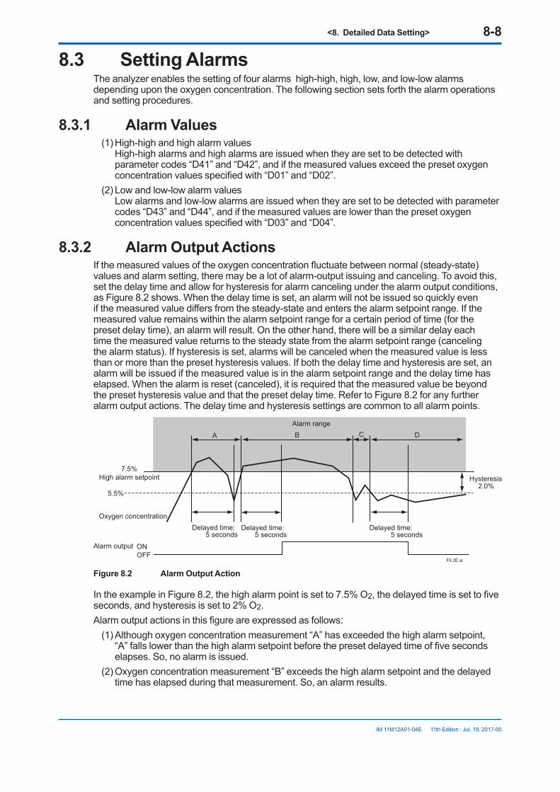
<8. Detailed Data Setting> 8-8
IM 11M12A01-04E 11th Edition : Jul. 19, 2017-00
8.3 Setting AlarmsThe analyzer enables the setting of four alarms high-high, high, low, and low-low alarms depending upon the oxygen concentration. The following section sets forth the alarm operations and setting procedures.
8.3.1 Alarm Values(1) High-high and high alarm values
High-high alarms and high alarms are issued when they are set to be detected with parameter codes “D41” and “D42”, and if the measured values exceed the preset oxygen concentration values specified with “D01” and “D02”.
(2) Low and low-low alarm values Low alarms and low-low alarms are issued when they are set to be detected with parameter codes “D43” and “D44”, and if the measured values are lower than the preset oxygen concentration values specified with “D03” and “D04”.
8.3.2 Alarm Output ActionsIf the measured values of the oxygen concentration fluctuate between normal (steady-state) values and alarm setting, there may be a lot of alarm-output issuing and canceling. To avoid this, set the delay time and allow for hysteresis for alarm canceling under the alarm output conditions, as Figure 8.2 shows. When the delay time is set, an alarm will not be issued so quickly even if the measured value differs from the steady-state and enters the alarm setpoint range. If the measured value remains within the alarm setpoint range for a certain period of time (for the preset delay time), an alarm will result. On the other hand, there will be a similar delay each time the measured value returns to the steady state from the alarm setpoint range (canceling the alarm status). If hysteresis is set, alarms will be canceled when the measured value is less than or more than the preset hysteresis values. If both the delay time and hysteresis are set, an alarm will be issued if the measured value is in the alarm setpoint range and the delay time has elapsed. When the alarm is reset (canceled), it is required that the measured value be beyond the preset hysteresis value and that the preset delay time. Refer to Figure 8.2 for any further alarm output actions. The delay time and hysteresis settings are common to all alarm points.
Delayed time: 5 seconds
7.5%High alarm setpoint
5.5%
Oxygen concentration
Alarm output ONOFF
Hysteresis2.0%
A B C DAlarm range
Delayed time: 5 seconds
Delayed time: 5 seconds
F8.2E.ai
Figure 8.2 Alarm Output Action
In the example in Figure 8.2, the high alarm point is set to 7.5% O2, the delayed time is set to five seconds, and hysteresis is set to 2% O2.Alarm output actions in this figure are expressed as follows:
(1) Although oxygen concentration measurement “A” has exceeded the high alarm setpoint, “A” falls lower than the high alarm setpoint before the preset delayed time of five seconds elapses. So, no alarm is issued.
(2) Oxygen concentration measurement “B” exceeds the high alarm setpoint and the delayed time has elapsed during that measurement. So, an alarm results.
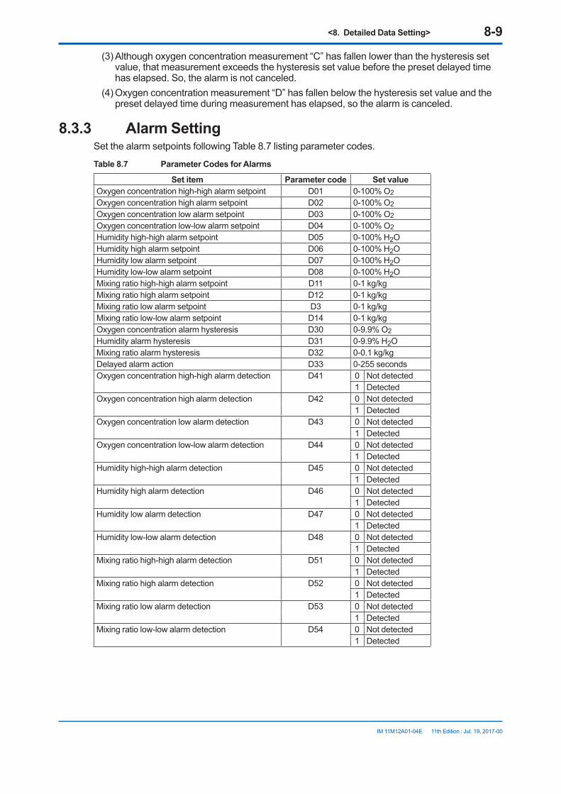
<8. Detailed Data Setting> 8-9
IM 11M12A01-04E 11th Edition : Jul. 19, 2017-00
(3) Although oxygen concentration measurement “C” has fallen lower than the hysteresis set value, that measurement exceeds the hysteresis set value before the preset delayed time has elapsed. So, the alarm is not canceled.
(4) Oxygen concentration measurement “D” has fallen below the hysteresis set value and the preset delayed time during measurement has elapsed, so the alarm is canceled.
8.3.3 Alarm SettingSet the alarm setpoints following Table 8.7 listing parameter codes.
Table 8.7 Parameter Codes for Alarms
Set item Parameter code Set valueOxygen concentration high-high alarm setpoint D01 0-100% O2Oxygen concentration high alarm setpoint D02 0-100% O2Oxygen concentration low alarm setpoint D03 0-100% O2Oxygen concentration low-low alarm setpoint D04 0-100% O2Humidity high-high alarm setpoint D05 0-100% H2OHumidity high alarm setpoint D06 0-100% H2OHumidity low alarm setpoint D07 0-100% H2OHumidity low-low alarm setpoint D08 0-100% H2OMixing ratio high-high alarm setpoint D11 0-1 kg/kgMixing ratio high alarm setpoint D12 0-1 kg/kgMixing ratio low alarm setpoint D3 0-1 kg/kgMixing ratio low-low alarm setpoint D14 0-1 kg/kgOxygen concentration alarm hysteresis D30 0-9.9% O2Humidity alarm hysteresis D31 0-9.9% H2OMixing ratio alarm hysteresis D32 0-0.1 kg/kgDelayed alarm action D33 0-255 secondsOxygen concentration high-high alarm detection D41 0 Not detected
1 DetectedOxygen concentration high alarm detection D42 0 Not detected
1 DetectedOxygen concentration low alarm detection D43 0 Not detected
1 DetectedOxygen concentration low-low alarm detection D44 0 Not detected
1 DetectedHumidity high-high alarm detection D45 0 Not detected
1 DetectedHumidity high alarm detection D46 0 Not detected
1 DetectedHumidity low alarm detection D47 0 Not detected
1 DetectedHumidity low-low alarm detection D48 0 Not detected
1 DetectedMixing ratio high-high alarm detection D51 0 Not detected
1 DetectedMixing ratio high alarm detection D52 0 Not detected
1 DetectedMixing ratio low alarm detection D53 0 Not detected
1 DetectedMixing ratio low-low alarm detection D54 0 Not detected
1 Detected

<8. Detailed Data Setting> 8-10
IM 11M12A01-04E 11th Edition : Jul. 19, 2017-00
CAUTIONEven with alarms set, if “Not detected” has been set in the above alarm detection, no alarm is issued. Be sure to set “Detected” in the above alarm detection if you use alarm features.
8.3.4 Default ValuesWhen the analyzer is delivered, or if data are initialized, the default alarm set values are as shown in Table 8.8.
Table 8.8 Alarm Setting Default Values
Set item Set valueOxygen concentration high-high alarm setpoint 100% O2
Oxygen concentration high alarm setpoint 100% O2
Oxygen concentration low alarm setpoint 0% O2
Oxygen concentration low-low alarm setpoint 0% O2
Humidity high-high alarm setpoint 100% H2OHumidity high alarm setpoint 100% H2OHumidity low alarm setpoint 0% H2OHumidity low-low alarm setpoint 0% H2OMixing ratio high-high alarm setpoint 1 kg/kgMixing ratio high alarm setpoint 1 kg/kgMixing ratio low alarm setpoint 0 kg/kgMixing ratio low-low alarm setpoint 0 kg/kgOxygen concentration alarm hysteresis 0.1% O2
Humidity alarm hysteresis 0.1% H2OMixing ratio alarm hysteresis 0.001 kg/kgDelayed alarm action 3 secondsHigh-high alarm detection Not detectedHigh alarm detection Not detectedLow alarm detection Not detectedLow-low alarm detection Not detected
8.4 Output Contact Setup8.4.1 Output Contact
Mechanical relays provide contact outputs. Be sure to observe relay contact ratings. (For details, see Section 2.1, “General Specifications.”) The following sets forth the operation mode of each contact output. Output contact 1 you can select open or closed contact when the contact is “operated”. For output contact 2, contact is closed. The relay for output contact 1 is energized when its contacts are closed and vice versa. Accordingly, when no power is supplied to the equipment, those contacts remain open. In addition, the relay for output contact 2 is energized when the corresponding contact is open and de-energized when that contact is closed.

<8. Detailed Data Setting> 8-11
IM 11M12A01-04E 11th Edition : Jul. 19, 2017-00
Table 8.9 Setting Output Contacts
Operating state When no power is applied to this equipmentOutput contact 1 Open (de-energized) or closed
(energized) selectable.Open
Output contact 2 Closed (de-energized) only. Closed
8.4.2 Setting Output Contact Set the output contacts following Table 8.10.
Table 8.10 Parameter Codes for Output Contact Setting
Set item Parameter code
Set value
Output contact 1Operation E10 0 Operated in closed status. (Normally de-energized)
1 Operated when open. (Normally energized) (Note 1)
Error E20 0 Not operated if an error occurs.1 Operated if an error occurs.
High-high alarm E21 0 Not operated if a high-high alarm occurs.1 Operated if a high-high alarm occurs. (Note 2)
High alarm E22 0 Not operated if a high alarm occurs.1 Operated if a high alarm occurs. (Note 2)
Low alarm E23 0 Not operated if a low alarm occurs.1 Operated if a low alarm occurs. (Note 2)
Low-low alarm E24 0 Not operated if a low-low alarm occurs.1 Operated if a low-low alarm occurs. (Note 2)
Maintenance E25 0 Not operated during maintenance.1 Operated during maintenance (see Section 8.3.1).
Calibration E26 0 Not operated during calibration.1 Operated during calibration (see Section 8.3.1).
Measurement range change
E27 0 Not operated when changing ranges.1 Operated when changing ranges. (Note 3)
Warm-up E28 0 Not operated during warming up.1 Operated during warming up.
Calibration gas pressure decrease
E29 0 Not operated while a calibration gas pressure decrease contact is being closed.
1 Operated while a calibration gas pressure decrease contact is being closed. (Note 4)
Unburnt gas detection
E32 0 Not operated while a unburnt gas detection contact is being closed.1 Operated while a unburnt gas detection contact is being closed. (Note 5)
Note 1: Output contact 2 remains closed. Note 2: The oxygen concentration alarm must be preset (see Section 8.4).Note 3: Range change answer-back signal. For this action, the range change must be preset during the setting of input contacts
(see Section 8.6).Note 4: Calibration gas pressure decrease answer-back signal. Calibration gas pressure decrease must be selected beforehand
during the setting of input contacts.Note 5: Non-combusted gas detection answer-back signals. “Non-combusted gas” detection must be selected during the setting of
input contacts.
WARNINGOutput contact 2 is linked to the detector’s heater power safety switch. As such, if output contact 2 is on, the heater power stops and an Error 1 (cell voltage abnormal) or Error 2 (heater temperature abnormal) occurs.
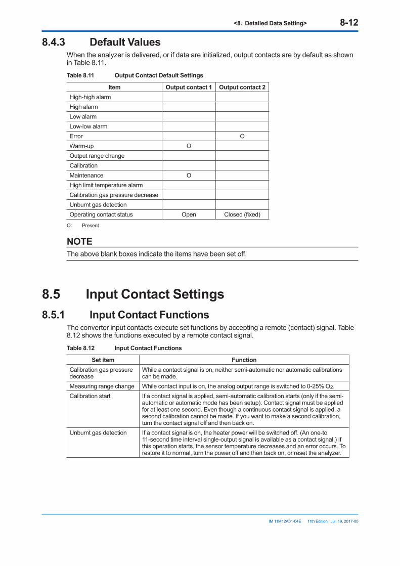
<8. Detailed Data Setting> 8-12
IM 11M12A01-04E 11th Edition : Jul. 19, 2017-00
8.4.3 Default ValuesWhen the analyzer is delivered, or if data are initialized, output contacts are by default as shown in Table 8.11.
Table 8.11 Output Contact Default Settings
Item Output contact 1 Output contact 2High-high alarmHigh alarmLow alarmLow-low alarmError OWarm-up OOutput range changeCalibrationMaintenance OHigh limit temperature alarmCalibration gas pressure decreaseUnburnt gas detectionOperating contact status Open Closed (fixed)
O: Present
NOTEThe above blank boxes indicate the items have been set off.
8.5 Input Contact Settings8.5.1 Input Contact Functions
The converter input contacts execute set functions by accepting a remote (contact) signal. Table 8.12 shows the functions executed by a remote contact signal.
Table 8.12 Input Contact Functions
Set item FunctionCalibration gas pressure decrease
While a contact signal is on, neither semi-automatic nor automatic calibrations can be made.
Measuring range change While contact input is on, the analog output range is switched to 0-25% O2.Calibration start If a contact signal is applied, semi-automatic calibration starts (only if the semi-
automatic or automatic mode has been setup). Contact signal must be applied for at least one second. Even though a continuous contact signal is applied, a second calibration cannot be made. If you want to make a second calibration, turn the contact signal off and then back on.
Unburnt gas detection If a contact signal is on, the heater power will be switched off. (An one-to 11-second time interval single-output signal is available as a contact signal.) If this operation starts, the sensor temperature decreases and an error occurs. To restore it to normal, turn the power off and then back on, or reset the analyzer.

<8. Detailed Data Setting> 8-13
IM 11M12A01-04E 11th Edition : Jul. 19, 2017-00
CAUTION• Measurement range switching function by an external contact input is available for analog
output 1 only and the range is fixed to 0-25%O2.• To conduct a semi-automatic calibration, be sure to set the Calibration setup mode to “Semi-
automatic” or “Automatic”.
8.5.2 Setting Input ContactTo set the input contacts, follow the parameter codes given in Table 8.13.
Table 8.13 Parameter Codes for Input Contact Settings
Set item Parameter code Set valueInput contact 1 (function) E01 0 Invalid
1 Calibration gas pressure decrease 2 Measuring range change 3 Calibration 4 Unburnt gas detection
Input contact 2 (function) E02 0 Invalid 1 Calibration gas pressure decrease 2 Measuring range change 3 Calibration 4 Unburnt gas detection
Input contact 1 (action) E03 0 Operated when closed 1 Operated when open
Input contact 2 (action) E04 0 Operated when closed 1 Operated when open
8.5.3 Default ValuesWhen the analyzer is delivered, or if data are initialized, the input contacts are all open.
8.6 Other Settings8.6.1 Setting the Date-and-Time
The following describe how to set the date-and-time. Automatic calibration works following this setting.Use parameter code “F10” to set the date-and-time.
<8. Detailed Data Setting> 8-14
IM 11M12A01-04E 11th Edition : Jul. 19, 2017-00
Table 8.14 Data-and-time Settings
Switch operation Display Description> ∧ ENT F10 Select the parameter code F10.
> ∧ ENT 00.01.01 If you touch the [ENT] key, the current date will be displayed. The display on the left indicates the date - January 1, 2000. To set June 21, 2000, follow the steps below:
> ∧ ENT 00.01.01 Touch the [>] key to move the position of the digit that is flashing to the right.
> ∧ ENT 00.06.01 Touch the [∧] key to change to 6.
> ∧ ENT 00.06.01 Touch the [>] key to move the position of the digit that is flashing to the right one digit.
> ∧ ENT 00.06.21 Touch the [∧] key to change to 2.
> ∧ ENT 00.06.21 Touch the [>] key to move the position of the digit that is flashing to the right one digit.
> ∧ ENT 07.18 Let the rightmost character flash, and touch the [>] key to display the time.Continuously touch the [>] key, then the date and time are alternately displayed. Displayed on the left is 7:18 a.m.Omitted here.
> ∧ ENT 14.30 Touch the [∧] key and enter the current time in same way as the date has been entered, on a 24-hour basis. 2:30 p.m. Displayed on the left means 2:40 p.m.
> ∧ ENT 14.30 If you touch the [ENT] key, all the digits flash.
> ∧ ENT 14.30 Touch the [ENT] key again to set the time.
> ∧ ENT F10 If you touch the [>] and [ENT] keys together, the parameter code selection display appears.
The symbol ( ) indicates that the corresponding keys are being touched, and the light characters indicate flashing.
8.6.2 Setting Periods over which Average Values are Calculated and Periods over which Maximum and Minimum Values Are Monitored
The equipment enables the display of oxygen concentration average values and maximum and minimum values under measurement (see Section 10.1, later in this manual). The following section describes how to set the periods over which oxygen concentration average values are calculated and maximum and minimum values are monitored.
n ProcedureUse the parameter-code table below to set the average, maximum and minimum oxygen concentration values. Periods over which average is calculated and periods over which maximum and minimum values are monitored can be set, ranging from 1 to 255 hours. If the set ranges are beyond the limits specified, an “Err” will be displayed.

<8. Detailed Data Setting> 8-15
IM 11M12A01-04E 11th Edition : Jul. 19, 2017-00
Table 8.15 Parameter Codes for Average, Maximum and Minimum Values
Set item Parameter code Set range UnitsPeriods over which average values are calculated
F11 1 to 255 Hours
Periods over which maximum and minimum values are monitored
F12 1 to 255 Hours
n Default ValueWhen the analyzer is delivered, or if data are initialized, periods over which average values are calculated are set to one hour, and periods over which maximum and minimum values are monitored are set to 24 hours.
8.6.3 Setting Fuels
n Input ParametersThe analyzer calculates the moisture content contained in exhaust gases. The following sets forth the fuel parameters necessary for calculation and their entries. The moisture quantity may be mathematically expressed by:
Moisture quantity =
=
= =
where,
Ao : Theoretical amount of air per unit quantity of fuel, m3 /kg (or m3 /m3 ) ............ 2 in Table 8.16
G: Actual amount of exhaust gas (including water vapor) per unit quantity of fuel, m3/kg (or m3 /m3)
Gw : Water vapor contained in exhaust gas per unit quantity of fuel (by hydrogen and moisture content in fuel), m3 /kg (or m3 /m3 ) ............ 1 in Table 8.16 Gw1: Water vapor contained in exhaust gas per unit quantity of fuel (moisture content in air), m3 /kg (or m3 /m3 )
Go: Theoretical amount of dry exhaust gas per unit quantity of fuel, m3 /kg (or m3 /m3 )
m: Air ratio
X : Fuel coefficient determined depending on low calorific power of fuel, m3 /kg (or m3 /m3 ) ... 3 in Table 8.16
Z : Absolute humidity of the atmosphere, kg /kg ....... Figure 8.4
(water vapor caused by combustion and water vapor contained in the exhaust gas)
..
actual exhaust gas(including water vapor) per fuel+ (water vapor contained in air for combustion)
x 100
Gw + (1.61 x Z x m x Ao)Go + Gw + (m - 1) Ao + (1.61 x Z x m x Ao)
x 100
Gw + (1.61 x Z x m x Ao )X + Ao x m
x 100
Gw + Gw1 G
x 100
..... Equation 1
............ Equation 2
Fill in the boxes with fuel parameters in Equation 2 above to calculate the moisture content. Use Ao, Gw and X shown in Table 8.16. If there are no appropriate fuel data in Table 8.16, use the following equations for calculation. Find the value of “Z” in Equations 1 and 2 using Japanese Standard JIS B 8222. If a precise measurement is not required, obtain the value of “Z” using a graph for the absolute humidity indicated by a dry and wet bulb hygrometer.

<8. Detailed Data Setting> 8-16
IM 11M12A01-04E 11th Edition : Jul. 19, 2017-00
For liquid fuelAmount of water vapor in exhaust gas (Gw) = (1/100) 1.24 (9h + w) (m /kg)
Theoretical amount of air (Ao) = 12.38 x (Hl/10000) – 1.36 (m /kg)
Low calorific power = Hl
X value = (3.37 / 10000) x Hx – 2.55 (m /kg)
where, Hl: low calorific power of fuel h: Hydrogen in fuel (weight percentage) w: Moisture content in fuel (weight percentage) Hx: Same as numeric value of Hl
For gas fuelAmount of water vapor in exhaust gas (Gw) = (1/100) (h2) + 1/2 ∑y (Cx Hy) + wv (m /m )
Theoretical amount of air (Ao) = 11.2 x (Hl/10000) (m /m )
Low calorific power = Hl
X value = (1.05 / 10000) x Hx (m /m )
where, Hl: low calorific power of fuel CxHy: Each hydrocarbon in fuel (weight percentage)
h2: Hydrogen in fuel (weight percentage) wv: Moisture content in fuel (weight percentage) Hx: Same as numeric value of Hl
For solid fuelAmount of water vapor in exhaust gas (Gw) = (1/100) 1.24 (9h + w) (m /kg)
Theoretical amount of air (Ao) = 1.01 x (Hl / 1000) + 0.56 (m /kg)
Low calorific power = Hl = Hh – 25 (9h + w) (kJ/kg)
X value = 1.11 - (0.106 / 1000 ) x Hx (m /m )
where, w: Total moisture content in use (weight percentage)
h: Hydrogen content (weight percentage)
The average hydrogen content of coal mined in Japan, which is a dry ash-free type, is 5.7 percent. Accordingly, "h" may be expressed mathematically by:
h = 5.7 [100 – (w + a) / 100] x (100 – w) / (100 – w1)
where, a: Ash content (%)
w1: Moisture content (%), analyzed on a constant humidity basis Hh: Higher calorific power of fuel (kJ/kg) Hl: Low calorific power of fuel (kJ/kg)
Hx: Same numeric value of Hl
3
3
3
3
3
3
3
3
3
3
3
3
3
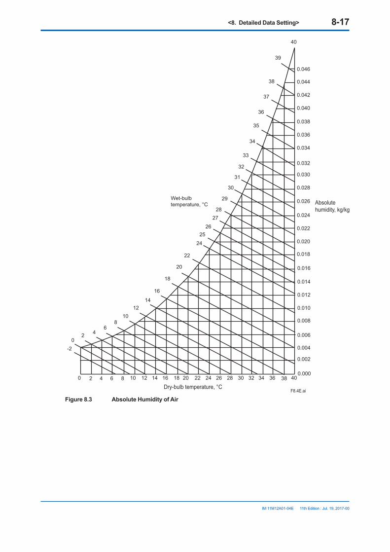
<8. Detailed Data Setting> 8-17
IM 11M12A01-04E 11th Edition : Jul. 19, 2017-00
40
0.046
0.044
0.042
0.040
0.038
0.036
0.034
0.032
0.030
0.028
0.026
0.024
0.022
0.020
0.018
0.016
0.014
0.012
0.010
0.008
0.006
0.004
0.002
0.0000 2 4 6 8 10 12 14 16 18 20 22 24 26 28 30 32 34 36 38 40
-20
2 46
810
1214
16
18
20
22
24
26
28
30
32
34
36
38
35
37
39
33
31
29
27
25
Wet-bulbtemperature, °C Absolute
humidity, kg/kg
Dry-bulb temperature, °CF8.4E.ai
Figure 8.3 Absolute Humidity of Air
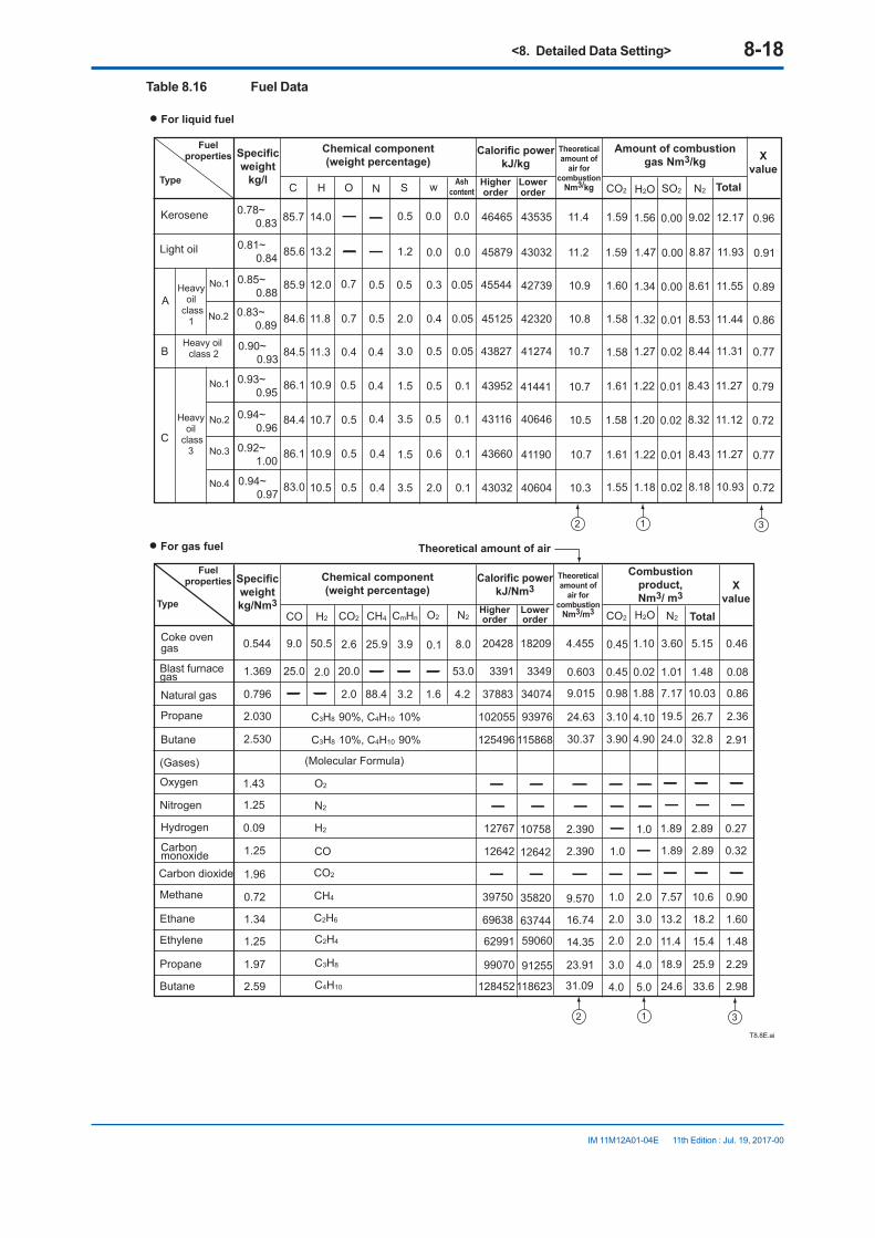
<8. Detailed Data Setting> 8-18
IM 11M12A01-04E 11th Edition : Jul. 19, 2017-00
Table 8.16 Fuel Data
• For liquid fuel
A
B
C
C H O N S w CO2 H2O SO2 N2
0.78~ 0.83
0.81~ 0.84
0.85~ 0.88
0.83~ 0.89
0.90~ 0.93
0.93~ 0.95
0.94~ 0.96
0.92~ 1.00
0.94~ 0.97
85.7
85.6
85.9
84.6
84.5
86.1
84.4
86.1
83.0
14.0
13.2
12.0
11.8
11.3
10.9
10.7
10.9
10.5
0.7
0.7
0.4
0.5
0.5
0.5
0.5
0.5
0.5
0.4
0.4
0.4
0.4
0.4
0.5
1.2
0.5
2.0
3.0
1.5
3.5
1.5
3.5
0.0 0.0
0.0 0.0
0.3
0.4
0.5
0.5
0.5
0.6
2.0
0.05
0.05
0.05
0.1
0.1
0.1
0.1
46465
45879
45544
45125
43827
43952
43116
43660
43032
43535
43032
42739
42320
41274
41441
40646
41190
40604
11.4
11.2
10.9
10.8
10.7
10.7
10.5
10.7
10.3
1.59
1.59
1.60
1.58
1.58
1.61
1.58
1.61
1.55
1.56
1.47
1.34
1.32
1.27
1.22
1.20
1.22
1.18
0.00
0.00
0.00
0.01
0.02
0.01
0.02
0.01
0.02
9.02
8.87
8.61
8.53
8.44
8.43
8.32
8.43
8.18
12.17
11.93
11.55
11.44
11.31
11.27
11.12
11.27
10.93
0.96
0.91
0.89
0.86
0.77
0.79
0.72
0.77
0.72
CO TotalH2 CO2 CH4 CmHn O2 N2 CO2 H2O N2
0.544
1.369
0.796
2.030
2.530
1.43
1.25
0.09
1.25
1.96
0.72
1.34
1.25
1.97
2.59
C3H8 90%, C4H10 10%
C3H8 10%, C4H10 90%
O2
N2
H2
CO
CO2
CH4
C2H6
C2H4
C3H8
C4H10
9.0
2.0 88.4 3.2 1.6 4.2
25.0 2.0 20.0 53.0
50.5 25.92.6 3.9 0.1 8.0 20428 18209
3391 3349
37883 34074
102055 93976
125496 115868
12767
12642
39750
69638
62991
99070
128452
10758
12642
35820
63744
59060
91255
118623
4.455
0.603
9.015
24.63
30.37
2.390
2.390
9.570
16.74
14.35
23.91
31.09
0.45
0.45
0.98
3.10
3.90
1.0
2.0
2.0
1.0
3.0
4.0
1.10
0.02
1.88
4.10
4.90
1.0
2.0
3.0
2.0
4.0
5.0
3.60
1.01
7.17
19.5
24.0
1.89
1.89
7.57
13.2
11.4
18.9
24.6
5.15
1.48
10.03
26.7
32.8
2.89
2.89
10.6
18.2
15.4
25.9
33.6
0.46
0.08
0.86
2.36
2.91
0.27
0.32
0.90
1.60
1.48
2.29
2.98
2 1 3
2 1 3
• For gas fuel
Specificweight
kg/l
Chemical component (weight percentage)
Calorific power kJ/kg
Theoretical amount of
air for combustion
Nm3/kg
Amount of combustion gas Nm3/kg
Ash content
Higher order
Lower order
X value
Total
Theoretical amount of air
Combustion product, Nm3/ m3
Calorific power kJ/Nm3
Chemical component (weight percentage)
Specificweight kg/Nm3
Theoretical amount of
air for combustion
Nm3/m3Higher order
Lower order
X value
Kerosene
Light oil
Heavy oil
class 1
Heavy oil class 2
Heavy oil
class 3
No.1
No.2
No.1
No.2
No.3
No.4
Fuelproperties
Type
Coke oven gas
Blast furnace gas
Natural gas
Propane
Butane
(Gases)
Oxygen
Nitrogen
Hydrogen
Carbon monoxideCarbon dioxide
Methane
Ethane
Ethylene
Propane
Butane
(Molecular Formula)
Fuelproperties
Type
T8.8E.ai

<8. Detailed Data Setting> 8-19
IM 11M12A01-04E 11th Edition : Jul. 19, 2017-00
n ProcedureUse the parameter code table below to set fuel values.
Table 8.17 Setting Fuel Values
Set item Parameter code Set value Engineering unitsAmount of water vapor in exhaust gas F20 0 to 5 m3/kg (m3)Theoretical amount of air F21 1 to 20 m3/kg (m3)X value F22 0 to 19.99Absolute humidity of the atmosphere F23 O to 1 kg/kg
n Default ValuesWhen the analyzer is delivered, or if data are initialized, parameter settings are by default, as shown in Table 8.18.
Table 8.18 Default Settings of Fuel Values
Item Default settingAmount of water vapor in exhaust gas 1.00 m3/kg (m3)Theoretical amount of air 1.00 m3/kg (m3)X value 1.00Absolute humidity of the atmosphere 0.1000 kg/kg
8.6.4 Setting Measurement Gas Temperature and PressureThe analyzer calculates the moisture content contained in exhaust gases and saturated water vapors from the entered gas temperature and pressure to obtain the relative humidity and dew point. Enter the exhaust gas temperature and pressure (absolute pressure) necessary for the calculation (see Section 10.1 later in this manual).
NOTEThe critical temperature of the saturated water vapor pressure is 374°C. If a gas temperature exceeding 370°C is entered, no correct calculation will be obtained.
n ProcedureTo set the gas temperature and pressure, follow the parameter code table for fuel setting.If you set a value exceeding the setting ranges, an error, ERR will result.
Table 8.19 Fuel Setting Default Value
Set item Parameter code Set value Engineering unitsExhaust gas temperature F13 0 to 3000 °CExhaust gas pressure F14 0 to 300 kPa abs.
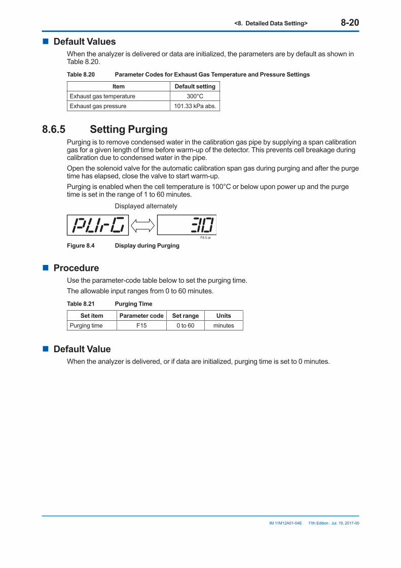
<8. Detailed Data Setting> 8-20
IM 11M12A01-04E 11th Edition : Jul. 19, 2017-00
n Default ValuesWhen the analyzer is delivered or data are initialized, the parameters are by default as shown in Table 8.20.
Table 8.20 Parameter Codes for Exhaust Gas Temperature and Pressure Settings
Item Default settingExhaust gas temperature 300°CExhaust gas pressure 101.33 kPa abs.
8.6.5 Setting PurgingPurging is to remove condensed water in the calibration gas pipe by supplying a span calibration gas for a given length of time before warm-up of the detector. This prevents cell breakage during calibration due to condensed water in the pipe.Open the solenoid valve for the automatic calibration span gas during purging and after the purge time has elapsed, close the valve to start warm-up.Purging is enabled when the cell temperature is 100°C or below upon power up and the purge time is set in the range of 1 to 60 minutes.
F8.5.ai
Displayed alternately
Figure 8.4 Display during Purging
n ProcedureUse the parameter-code table below to set the purging time.The allowable input ranges from 0 to 60 minutes.
Table 8.21 Purging Time
Set item Parameter code Set range UnitsPurging time F15 0 to 60 minutes
n Default ValueWhen the analyzer is delivered, or if data are initialized, purging time is set to 0 minutes.
<9. Calibration> 9-1
IM 11M12A01-04E 11th Edition : Jul. 19, 2017-00
9. Calibration
9.1 Calibration Briefs9.1.1 Principle of Measurement with a zirconia oxygen
analyzerThis section sets forth the principles of measurement with a zirconia oxygen analyzer before detailing calibration.A solid electrolyte such as zirconia allows the conductivity of oxygen ions at high temperatures. Therefore, when a zirconia-plated element with platinum electrodes on both sides is heated up in contact with gases having different oxygen partial pressures on each side, the element shows the action of the concentration cell. In other words, the electrode in contact with a gas with a higher oxygen partial pressure acts as a negative electrode. As the gas comes in contact with the zirconia element in this negative electrode, oxygen molecules in the gas acquire electrons and become ions. Moving in the zirconia element, they eventually arrive at the positive electrode on the opposite side. There, the electrons are released and the ions return to the oxygen molecules. This reaction is indicated as follows: Negative electrode: O2 + 4e 2 O 2-
Positive electrode: 2 O 2- O2 + 4 eThe electromotive force E (mV) between the two electrodes, generated by the reaction, is governed by Nernst’s equation as follows: E = -RT/nF ln Px/Pa......................................................Equation (1)where, R: Gas constant T: Absolute temperature n: 4 F: Faraday’s constant Px: Oxygen concentration in a gas in contact with the negative zirconia electrode (%) Pa: Oxygen concentration in a gas in contact with the positive zirconia electrode (%)Assuming the zirconia element is heated up to 750°C, then we obtain equation (2) below: E = -50.74 log Px/Pa......................................................Equation (2)With this analyzer, the sensor (zirconia element) is heated up to 750°C, so Equation (2) is valid. At that point, the relationship as in Figure 9.1 is effected between the oxygen concentration of the measurement gas in contact with the positive electrode and the electromotive force of the sensor (cell), where a comparison gas of air is used on the negative electrode side.

<9. Calibration> 9-2
IM 11M12A01-04E 11th Edition : Jul. 19, 2017-00
0.1 0.5 1 5 10 21.0 50 100
120
100
80
60
40
20
0
-20
-40
0.51 vol%O2,81.92mV(Zero origin of calibration)
21.0 vol%O2, 0mV(Span origin of calibration)
Oxygen concentration (vol % O2)
Cellvoltage(mV)
F9.1E.ai
Figure 9.1 Oxygen Concentration in a Measurement Gas vs. Cell Voltage (21 vol%O2 Equivalent)
The measurement principles of a zirconia oxygen analyzer have been described above. However, the relationship between oxygen concentration and the electromotive force of a cell is only theoretical. Usually, in practice, a sensor shows a slight deviation from the theoretical value. This is the reason why calibration is necessary. To meet this requirement, an analyzer calibration is conducted so that a calibration curve is obtained, which corrects the deviation from the theoretical cell electromotive force.
9.1.2 Measurement Principle of Zirconia Humidity AnalyzerA solid electrolyte such as zirconia allows the conduction of oxygen ions at high temperatures. Therefore, when a zirconia-plated element with platinum electrodes on both sides is heated up in contact with gases having different partial-oxygen pressures on each side, oxygen ions flow from a high partial-oxygen pressure to a low partial-oxygen pressure, causing a voltage. When a sample gas introduced into the zirconia-plated element with the measurement electrode, and air (21.0 vol % O2) is flowed through the reference electrode, an electromotive force (mV) is produced between the two electrodes, governed by Nernst’s equation as follows: E = - RT/nF log e y/a ………………………… Equation (1) where, R = Gas constant T = Absolute temperature n: 4 F = Faraday’s constant y = O2 vol % on the zirconia element measurement electrode a = O2 vol % to 21.0 vol % O2 on the zirconia element reference electrodeThe humidity analyzer uses a sample gas composed of water vapor and air.(A) For the vol % H2O measurement
x:Assuming that H2O vol % in a mixed gas is measured: y = (100 – x) 3 0.21 …………………. Equation (2)

<9. Calibration> 9-3
IM 11M12A01-04E 11th Edition : Jul. 19, 2017-00
From the above equations (1) and (2), we obtain: E = -K log y/a = -Klog [(100 – x) 30.21] /21 = - K log (1 –0.01 x) ……………… Equation (3) where, K = ConstantUsing the above equation (3), we can calculate the water vapor in vol % from the electromotive force.
Sample gasComparison water vapor
+
-
H2O concentration indicator
Electrode
Water vapor 100%
Air100%
100%
H2O79%
21%O2
N2
y%
x%
Sample gas composition
Zirconia element
F9-1E.ai
Figure 9.2 Schematic Diagram of Measurement Principle
(B) For the “mixing ratio” measurement
Assuming that the mixing ratio is rkg/kg, then “r” can be calculated from the value of H2O vol % as follows: r = 0.622 3 x/(100 – x) …………… Equation (4)From the above equations (1), (2) and (4), we obtain: E = -K log y/a = -K log 50.622 3 21/(0.622 + r)/216 = -K log 0.622/(0.622 + r) … …… Equation (5) where, K = ConstantWith Equation (5), we can obtain the mixing ratio rkg/kg from the electromotive force.
120
100
80
60
40
20
00.1 1 10 100
Cel
l out
put,
mV
E =
-50.
74 lo
g P
X/2
0.6
Oxygen concentration vs. cell output
Oxygen concentration PX (%O2)
F9-2E.ai
Figure 9.3

<9. Calibration> 9-4
IM 11M12A01-04E 11th Edition : Jul. 19, 2017-00
100
90
80
70
60
50
40
30
20
10
00 1 2 3 4 5 6 7 8 9 10 11 12 13 14 15 16 17 18 19 20 21 22
1.0
0.9
0.8
0.7
0.6
0.5
0.4
0.3
0.2
0.1
0.0
Humidity, vol % H2O
Mixing ratio, kg/kgH
umid
ity, v
ol %
H2O
Oxygen concentration, vol % O2
Mix
ing
ratio
kg/
kg
Oxygen concentration vs. Humidity, Mixing ratioF9-3E.ai
Figure 9.4
9.1.3 Calibration GasA gas with a known oxygen concentration is used for calibration. Normal calibration is performed using two different gases: a zero gas of low oxygen concentration and a span gas of high oxygen concentration. In some cases, only one of the gases needs to be used for calibration. However, even if only one of the gases is normally used, calibration using both gases should be done at least once.The zero gas normally used has an oxygen concentration of 0.95 to 1.0 vol%O2 with a balance of nitrogen gas (N2). The span gas widely used is clean air (at a dew-point temperature below -20°C and free of oily mist or dust, as in instrument air).
9.1.4 CompensationThe deviation of a measured value from the theoretical cell electromotive force is checked by the method in Figure 9.5 or 9.6.Figure 9.5 shows a two-point calibration using two gases: zero and span. Cell electromotive forces for a span gas with an oxygen concentration p1 and a zero gas with an oxygen concentration p2 are measured while determining the calibration curve passing between these two points. The oxygen concentration of the sample gas is determined from this calibration curve. In addition, the calibration curve corrected by calibration is compared with the theoretical calibration curve for determining the zero correction ratio represented by B/A x 100 (%) on the basis of A, B and C shown in Figure 9.5 and a span correction ratio of C/A x 100 (%). If the zero correction ratio exceeds the range of 100 ± 30% or the span correction ratio becomes larger than 0 ± 18%, calibration of the sensor becomes impossible.
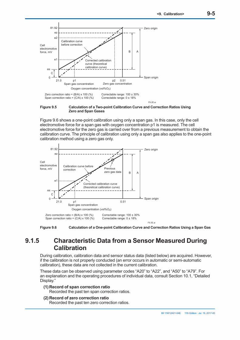
<9. Calibration> 9-5
IM 11M12A01-04E 11th Edition : Jul. 19, 2017-00
21.0 p1 p2 0.51
81.92ez
e2
e1
es
0C
AB
Zero correction ratio = (B/A) x 100 (%) Correctable range: 100 ± 30%Span correction ratio = (C/A) x 100 (%) Correctable range: 0 ± 18%
Cell electromotive force, mV
Calibration curve before correction
Corrected calibration curve (theoretical calibration curve)
Zero origin
Span gas concentration Zero gas concentration
Span origin
Oxygen concentration (vol%O2)
F9.2E.ai
Figure 9.5 Calculation of a Two-point Calibration Curve and Correction Ratios Using Zero and Span Gases
Figure 9.6 shows a one-point calibration using only a span gas. In this case, only the cell electromotive force for a span gas with oxygen concentration p1 is measured. The cell electromotive force for the zero gas is carried over from a previous measurement to obtain the calibration curve. The principle of calibration using only a span gas also applies to the one-point calibration method using a zero gas only.
21.0 p1 0.51
81.92ez
e1
es
0C
AB
Zero correction ratio = (B/A) x 100 (%) Correctable range: 100 ± 30%Span correction ratio = (C/A) x 100 (%) Correctable range: 0 ± 18%
Cell electromotive force, mV
Calibration curve before correction Previous
zero gas data
Corrected calibration curve(theoretical calibration curve)
Zero origin
Span origin
Span gas concentrationOxygen concentration (vol%O2)
F9.3E.ai
Figure 9.6 Calculation of a One-point Calibration Curve and Correction Ratios Using a Span Gas
9.1.5 Characteristic Data from a Sensor Measured During Calibration
During calibration, calibration data and sensor status data (listed below) are acquired. However, if the calibration is not properly conducted (an error occurs in automatic or semi-automatic calibration), these data are not collected in the current calibration.These data can be observed using parameter codes “A20” to “A22”, and “A50” to “A79”. For an explanation and the operating procedures of individual data, consult Section 10.1, “Detailed Display.”
(1) Record of span correction ratio Recorded the past ten span correction ratios.
(2) Record of zero correction ratio Recorded the past ten zero correction ratios.
<9. Calibration> 9-6
IM 11M12A01-04E 11th Edition : Jul. 19, 2017-00
(3) Response time You can monitor the response time provided that a two-point calibration has been done in semi-automatic or automatic calibration.
(4) Cell’s internal resistance The cell’s internal resistance gradually increases as the cell (sensor) deteriorates. You can monitor the values measured during the latest calibration. However, these values include the cell’s internal resistance and other wiring connection resistance. So, the cell’s degrading cannot be estimated from these values only. When only a span calibration has been made, these values will not be measured, and previously measured values will remain.
(5) Robustness of a cell The robustness of a cell is an index for predicting the remaining life of a sensor and is expressed in a number on four levels.
9.2 Calibration ProceduresNOTECalibration should be made under normal operating conditions (if the probe is connected to a furnace, the analyzer will undergo calibration under the operating conditions of the furnace). To make a precise calibration, conduct both zero and span calibrations.
The following sets forth the required calibration settings:
9.2.1 ModeThere are three calibration modes available:
(1) Manual calibration which allows zero and span calibrations or either one manually in turn;(2) Semi-automatic calibration which lets calibration start with the touch panel or a contact
input, and undergoes a series of calibration operations following preset calibration periods and stabilization time.
(3) Automatic calibration which is carried out automatically following preset calibration periods.
Calibrations are limited by the following mode selection:
• When Manual calibration is selected: Manual calibration only can be conducted. (This mode does not allow semi-automatic
calibration with a contact input nor automatic calibration even when its start-up time has reached.)
• When Semi-automatic calibration is selected: This mode enables manual and semi-automatic calibrations to be conducted. (The mode, however, does not allow automatic calibration even when its start-up time has
reached.)
• When Automatic calibration is selected: This calibration can be conducted in any mode.
9.2.2 Calibration ProcedureSelect both span and zero calibrations or span calibration only or zero calibration only. Usually select span and zero calibrations.

<9. Calibration> 9-7
IM 11M12A01-04E 11th Edition : Jul. 19, 2017-00
9.2.3 Zero gas ConcentrationSet the oxygen concentration for zero calibration. Enter the oxygen concentration for the zero gas in the cylinder used.
9.2.4 Span gas ConcentrationSet the oxygen concentration for span calibration. If instrument air is used as the span gas, enter 21 %O2.When using the ZO21S Standard Gas Unit (for use of the atmospheric air as a span gas), use a hand-held oxygen analyzer to measure the actual oxygen concentration, and then enter it.
NOTE• When instrument air is used for the span calibration, remove the moisture from the
instrument air at a dew-point temperature of -20°C and also remove any oily mist and dust from that air.
• If dehumidifying is not enough, or if foul air is used, the measurement accuracy will be adversely affected.
9.2.5 Calibration Time• When the calibration mode is in manual:
First set the hold (output stabilization) time. This indicates the time required from the end of calibration to entering a measurement again. This time, after calibration, the measurement gas enters the sensor to set the time until the output returns to normal. The output remains held after completing the calibration operation until the hold (output stabilization) time elapses. The calibration time set ranges from 00 minutes, 00 seconds to 60 minutes, 59 seconds. For more details, consult Section 8.2,”Output Hold Setting.” When the calibration mode is in semi-automatic, set the hold (output stabilization) time and calibration time. The calibration time is the time required from starting the flow of the calibration gas to reading out the measured value. The set calibration time is effective in conducting both zero and span calibrations. The calibration time set ranges from 00 minutes, 00 seconds to 60 minutes, 59 seconds. Figure 9.7 shows the relationship between the calibration time and hold (output stabilization) time.
Analog output remains hold(when output remains hold)
Calibration start (contact or switch input)
Span calibration (span gas valve open)
Zero calibration (zero gas valve open)
Analog output status
Calibration time
Calibration time
Hold (output stabilization) time
F9.4E.ai
Figure 9.7 Calibration and Hold (Output stabilization) Time Settings

<9. Calibration> 9-8
IM 11M12A01-04E 11th Edition : Jul. 19, 2017-00
• When the calibration mode is in automatic: In addition to the above hold (output stabilization) time and calibration time, set the interval, start date, and start time. Interval means the calibration intervals ranging from 000 days, 00 hours to 255 days, 23 hours. Set the first calibration day and the start-calibration time to the start date and start time respectively. After the first calibration is carried out, the next calibration will be executed according to the preset calibration intervals.
n SettingWhen setting calibration timing requirements, bear the following precautions in mind:
NOTE(1) If the calibration interval is shorter than the sum of hold (output stabilization) time plus
calibration time, the second calibration start time will conflict with the first calibration. In such a case, the second calibration will not be conducted. (When both zero and span calibrations are to be performed, the calibration time is double that required for a single (zero or span) calibration.)
(2) For the same reason, if the calibration start time conflicts with manual calibration or semi-automatic calibration, the current calibration will not be conducted.
(3) If the calibration time conflicts with maintenance service operation, calibration will start after completing the maintenance service operation (see Section 8.2.1, earlier in this manual).
(4) If 000 days, 00 hours are set for the calibration intervals, only the first calibration will be conducted; a second or later calibration will not be conducted.
(5) If a past date is set to the calibration start day, no calibration will be conducted.
Table 9.1 Parameter Codes for Calibration Setting
Set Item Parameter code Set value Engineering
unit Zero gas concentration B01 Set Zero gas concentration %O2
Span gas concentration B02 Set Span gas concentration %O2
Calibration mode B03 0 Manual calibration 1 Semi-automatic and manual 2 Automatic, semi-automatic, and manual
Hold (Output stabilization) time B04 0 minutes 0 seconds to 60 minutes 59 seconds MM.SSCalibration time B05 0 minutes 0 seconds to 60 minutes 59 seconds MM.SSCalibration interval B06 0 days 0 hours to 255 days 23 hours Date and timeStart date and time B07 Date and time of first calibration YY.MM.
DD.HH.MMCalibration procedure B08 0 Zero and span
1 Span only 2 Zero only
n Default ValuesWhen the analyzer is delivered, or if data are initialized, the calibration settings are by default, as shown in Table 9.2.

<9. Calibration> 9-9
IM 11M12A01-04E 11th Edition : Jul. 19, 2017-00
Table 9.2 Default Settings for Calibration
Item Default SettingCalibration mode ManualCalibration procedure Span - zeroZero gas (oxygen) concentration 1.00%Span gas (oxygen) concentration 21.00%Hold (Output stabilization) time 10 minutes, 00 secondsCalibration time 10 minutes, 00 secondsCalibration interval 30 days, 00 hoursStart date and time 00 (YY) 01 (MM) 01(DD) 00:00
9.3 Calibration9.3.1 Manual Calibration
For manual calibration, consult Section 7.11, “Calibration,” earlier in this manual.
9.3.2 Semi-automatic Calibration(1) Calibration startup using infrared switches
Table 9.3 Semi-automatic Calibration Procedure
Switch operation Display Description> ∧ ENT b11 Change the parameter code to b11. (Previous operations omitted)
> ∧ ENT SA-CAL Touch the [ENT] key to display "SA-CAL" (Semi Auto CAL).
> ∧ ENT SPAn/20.84
Touch the [ENT] key again to open the span gas solenoid valve.The span gas then flows. "SPAn" and the currently measured value are alternately displayed. If the "output hold" is set, the output hold will start at this time.
> ∧ ENT ZEro/0.89
If the set calibration time elapses, the span gas solenoid valve closes automatically, the zero gas solenoid valve opens and the zero gas flows. "ZEro" and the currently measured value are displayed alternately.
> ∧ ENT CALEnd End If the set calibration time elapses, the zero gas solenoid valve then closes automatically. The ''CALEnd'' flashes until the set output stabilization time elapses.
> ∧ ENT Basic paneldisplay
If the output stabilization time elapses, the basic panel display then appears. Output holding will be released.
When “CAL Err” appears, a calibration coefficient alarm (alarm 6 or 7) may have occurred.Press [ENT] key to return to basic panel display. Check the alarm number. Refer to Subsection 12.2.2.2, Alarm 6, or Subsection
12.2.2.3, Alarm 7, remove the cause, and then recalibrate the instrument.
The symbol [ ] indicates that the corresponding keys are being touched, and the light characters indicate flashing.“/” indicates that both are displayed alternately.
(2) To start calibration using an input contact, follow these steps: • Make sure that Calibration start has been selected in the Input contacts display (see
Section 8.5, earlier in this manual). • Apply an input contact to start calibration.(3) To stop calibration midway, follow these steps:
Touch the [>] key and [ENT] key together. The calibration will stop and the output stabilization time will be set up. Touch the [>] key once again to return to the basic panel display and the analyzer will be in normal measurement.

<9. Calibration> 9-10
IM 11M12A01-04E 11th Edition : Jul. 19, 2017-00
9.3.3 Automatic CalibrationNo execution operations are required for automatic calibration. Automatic calibration starts in accordance with a preset start day and time. Calibration is then executed at preset intervals.
NOTEBefore conducting a semi-automatic or automatic calibration, run the automatic calibration unit beforehand to obtain a calibration flow of 600 ± 60 ml/min.

<10. Other Functions> 10-1
IM 11M12A01-04E 11th Edition : Jul. 19, 2017-00
10. Other Functions
10.1 Detailed DisplaySelect the desired parameter code to display the detailed operation data (see Table 10.1, “Parameter Codes for Detailed Operation Data”.
NOTERefer to Section 7.8, “Setting Display Item”, for parameter code “A00”.
Table 10.1 Parameter Codes for Detailed Operation Data
Code Item Engineering unit Code Item Engineering
unitA00 Selection
of display items
0 Oxygen concentration A50 Span correction ratio 0 %1 Oxygen analyzer (0.0) A51 Span correction ratio 1 %2 Oxygen analyzer (0.0) A52 Span correction ratio 2 %3 Analog output selected A53 Span correction ratio 3 %
A01 Oxygen concentration % O2 A54 Span correction ratio 4 %A02 Humidity %H2O A55 Span correction ratio 5 %A03 Mixing ratio kg/kg A56 Span correction ratio 6 %A04 Relative humidity % A57 Span correction ratio 7 %A05 Dew point °C A58 Span correction ratio 8 %A06 Air ratio A59 Span correction ratio 9 %A07 Cell temperature °C A60 Zero correction ratio 0 %A08 Cold junction temperature °C A61 Zero correction ratio 1 %A09 Meas. gas temperature °C A62 Zero correction ratio 2 %A10 Amount of water vapor in exhaust gas % A63 Zero correction ratio 3 %A11 Cell voltage mV A64 Zero correction ratio 4 %A12 TC voltage mV A65 Zero correction ratio 5 %A15 Cold junction voltage mV A66 Zero correction ratio 6 %A16 Output current mA A67 Zero correction ratio 7 %A20 Cell response time Seconds A68 Zero correction ratio 8 %A21 Cell internal resistance Ω A69 Zero correction ratio 9 %A22 Cell robustness A70 Calibration history 0 YY.MM.DD/
HH.MMA23 Heater on-time ratio % A71 Calibration history 1 YY.MM.DD/
HH.MMA24 Oxygen concentration (with time
constant) % O2 A72 Calibration history 2 YY.MM.DD/
HH.MMA25 Humidity (with time constant) %H2O A73 Calibration history 3 YY.MM.DD/
HH.MMA26 Mixing ratio (with time constant) kg/kg A74 Calibration history 4 YY.MM.DD/
HH.MMA30 Max. oxygen concentration % O2 A75 Calibration history 5 YY.MM.DD/
HH.MMA31 Occurrence of maximum oxygen
concentrationYY.MM.DD/HH.MM
A76 Calibration history 6 YY.MM.DD/HH.MM

<10. Other Functions> 10-2
IM 11M12A01-04E 11th Edition : Jul. 19, 2017-00
A32 Min. oxygen concentration % O2 A77 Calibration history 7 YY.MM.DD/HH.MM
A33 Occurrence of minimum oxygen concentration
YY.MM.DD/HH.MM
A78 Calibration history 8 YY.MM.DD/HH.MM
A34 Average oxygen concentration % O2 A79 Calibration history 9 YY.MM.DD/HH.MM
A35 Maximum humidity %H2O A80 Time YY.MM.DD/HH.MM
A36 Occurrence of maximum humidity YY.MM.DD/HH.MM
A90 Software revision
A37 Minimum humidity %H2OA38 Occurrence of minimum humidity YY.MM.DD/
HH.MM A39 Average humidity %H2OA40 Maximum humidity kg/kgA41 Occurrence of maximum humidity YY.MM.DD/
HH.MM A42 Minimum humidity kg/kgA43 Occurrence of minimum humidity YY.MM.DD/
HH.MM A44 Average humidity kg/kg
10.1.1 Oxygen ConcentrationThe oxygen concentration in the process gas is displayed (consult Section 9.1.1, earlier in this manual).
10.1.2 HumidityThe moisture content contained in air is displayed where the process gas contains water vapors and air (refer to Section 9.1.1, earlier in this manual).
10.1.3 Mixing RatioWhere the process gas contains water vapors and air, their mixing ratio is displayed (refer to Section 9.1.1, earlier in this manual).
10.1.4 Relative HumidityThe relative humidity “U” may be obtained using the following theoretical equation (JIS Z 8806). U = e/es x100 where, e = Water vapor pressure of moist air es = Saturated water vaporSince the gas-pressure ratio is equal to the volume ratio, the above equation may be expressed mathematically by: U = P x H/ es x100 where, P = Gas pressure H = Humidity (volume ratio)The saturated water vapor pressure es is determined by a gas temperature, so the relative humidity can be obtained by entering the parameters. Use parameter F13 for temperature entry. Use parameter F14 for pressure entry.
10.1.5 Dew PointThe dew point is the temperature at which a water vapor pressure in the moist air is equal to the saturated water vapor pressure.
<10. Other Functions> 10-3
IM 11M12A01-04E 11th Edition : Jul. 19, 2017-00
The water vapor pressure in the moist air can be obtained from the gas pressure and volume ratio (= pressure ratio), as given below. e = P x H where, e = Water vapor pressure in moist air P = Gas pressure H = Humidity (volume ratio)Use the above equation to find the water vapor in the moist air, and use the theoretical equation (JIS Z 8806) to obtain the temperature at which that water vapor is equal to the saturated water vapor pressure.
10.1.6 Air Ratio“Air ratio” is defined as the ratio of (the amount of air theoretically required to completely burn all the fuel) to (the amount of air actually supplied).For this equipment, the air ratio will be obtained in a simplified way by measuring the oxygen concentration in the exhaust gas. The air ratio may be expressed mathematically by:
m = x 21(21- oxygen concentration)1
If you use the air ratio data for estimating the combustion efficiency, etc., check that no air is leaking in beforehand and that the measured value has not been affected by any interference gas (CH4, CO, H2, etc.).
10.1.7 Cell TemperatureThis indicates the cell (sensor) temperature, usually indicating 750°C., obtainable from the thermoelectromotive force and cold junction temperature described below.
10.1.8 Process Gas TemperatureA process gas temperature set with parameter code F13 is displayed.
10.1.9 C. J. TemperatureThis is the internal (where the electronics is installed) temperature of equipment, which compensates for the cold junction temperature for a thermocouple measuring the cell temperature. If this temperature exceeds 85°C, the electronics may fail. When the ZR202G is used, the maximum C. J. temperature will be 150°C. If the internal temperature exceeds this, take measures to reduce the temperature such as by not exposing the equipment to radiation.
10.1.10 Amount of Water Vapor in Exhaust GasCalculate the water vapor in the combusted exhaust gas using parameters set in Section 8.6.3, “Setting Fuels.” Use the following equation for calculation:
Moisture (water vapor) = (amount of water vapor per unit quantity of fuel) + (moisture in air) /total amount of exhaust gas = X + Ao x m
Gw + 1.61 x Z x Ao x m
where, Gw = Amount of water vapor in exhaust gas, m3/kg (or m3/m3) Z = Atmospheric absolute humidity, kg/kg Ao = Theoretical air amount, m3/kg (or m3/m3) m = Air ratio X = Fuel coefficient, Nm3/kg or m3/m3
For details on parameters, see Section 8.6.3, “Setting Fuels,” earlier in this manual.

<10. Other Functions> 10-4
IM 11M12A01-04E 11th Edition : Jul. 19, 2017-00
10.1.11 Cell VoltageThe cell (sensor) voltage will be an index to determine the amount of degradation of the sensor. The cell voltage corresponds to the oxygen concentration currently being measured. If the indicated voltage approximates the ideal value (corresponding to the measured oxygen concentration), the sensor will be assumed to be normal.The ideal value of the cell voltage (E), when the oxygen concentration measurement temperature is controlled at 750°C., may be expressed mathematically by: E = -50.74 log (Px/Pa) [mV] where, Px: Oxygen concentration in the sample gas Pa: Oxygen concentration in the reference gas, (21 vol%O2)Table 10.2 shows oxygen concentration versus cell voltage.
Table 10.2 Oxygen Concentration Vs. Cell Voltage, (cell temperature: 750°C)
%O2 0.1 0.2 0.3 0.4 0.5 0.6 0.7 0.8 0.9 mv 117.83 102.56 93.62 87.28 82.36 78.35 74.95 72.01 69.41
%O2 1 2 3 4 5 6 7 8 9 mv 67.09 51.82 42.88 36.54 31.62 27.61 24.21 21.27 18.67
%O2 10 21.0 30 40 50 60 70 80 90 mv 16.35 0 -7.86 -14.2 -19.2 -23.1 -26.5 -29.5 -32.1
%O2 100 mv -34.4
T10.2E.ai
10.1.12 Thermocouple VoltageThe cell temperature is measured with a Type K (chromel-alumel) thermocouple. The thermocouple cold junction is located in the detector terminal box. The cell temperature and the thermocouple voltage (including the voltage corresponding to the cold junction temperature) are displayed.
10.1.13 Cold Junction VoltageThis equipment uses temperature-measurement ICs that measure the cold junction temperatures. The voltage measured by those ICs is displayed.
10.1.14 Current OutputThe analog output current is displayed.
10.1.15 Response TimeThe cell’s response time is obtained in the procedure shown in Figure 10.1. If only either zero or span calibration has been carried out, the response time will not be measured just as it will not be measured in manual calibration.

<10. Other Functions> 10-5
IM 11M12A01-04E 11th Edition : Jul. 19, 2017-00
mA
90%100%
The response time is obtained after the corrected calibration curve has been found. The response time is calculated, starting at the point corresponding to 10% of the analog output up to the point at 90% of the analog output span. That is, this response time is a 10 to 90% response.
10% of analog output span
Five minutes maximum
Response time
Start calibrationTime
Calibration complete
F10.1E.ai
Figure 10.1 Typical Response Time characteristics
10.1.16 Cell’s Internal ResistanceA new cell (sensor) indicates its internal resistance of 200 Ω maximum. As the cell degrades, so will the cell’s internal resistance increase. The degradation of the cell cannot be found only by changes in cell’s internal resistance, however. Those changes in the cell’s internal resistance will be a hint to knowing the sensor is degrading. The updated values obtained during the calibration are displayed.
10.1.17 Robustness of a CellThe robustness of a cell is an index for predicting the remaining life of a sensor and is expressed as one of four time periods during which the cell may still be used:
(1) more than a year(2) more than six months(3) more than three months(4) less than one month
The above four time periods are tentative and only used for preventive maintenance, not for warranty of the performance.This cell’s robustness can be found by a total evaluation of data involving the response time, the cell’s internal resistance, and calibration factor. However, if a zero or span calibration was not made, the response time cannot be measured. In such a case, the response time is not used as a factor in evaluating the cell’s robustness.
Table 10.3 Cell Robustness and Service Life
Cell robustness Cell s service life5 One year min.3 Six months min.2 Three months min.1 One month max.
10.1.18 Heater On-Time RatioThe probe sensor is heated to and maintained at 750°C. When the sample gas temperature is high, the amount of heater ON-time decreases.

<10. Other Functions> 10-6
IM 11M12A01-04E 11th Edition : Jul. 19, 2017-00
10.1.19 Oxygen Concentration (with time constant), Humidity (with time constant), and Mixing Ratio (with time constant)
When the output damping is specified in the mA-output range setting, the corresponding time constant is also displayed.
10.1.20 Maximum Oxygen Concentration, Humidity, and Mixing Ratio
The maximum oxygen concentration and the time of its occurrence during the period specified in the Averaging display are displayed. If the setup period elapses, the maximum oxygen concentration that has been displayed so far will be cleared and a new maximum oxygen concentration will be displayed. If the setup period of time is changed, the current maximum oxygen concentration will be displayed (for more details, see Section 8.6.2 earlier in this manual).
10.1.21 Minimum Oxygen Concentration, Humidity, and Mixing Ratio
The minimum oxygen concentration and the time of its occurrence during the period specified in the Averaging display are displayed. If the setup period elapses, the minimum oxygen concentration that has been displayed so far will be cleared and a new minimum oxygen concentration will be displayed. If the setup period of time is changed, the current minimum oxygen concentration will be displayed (for more details, see Section 8.6.2 earlier in this manual).
10.1.22 Average Oxygen Concentration, Humidity, and Mixing Ratio
The average oxygen concentration during the periods over which average values are calculated is displayed. If the setup period elapses, the average oxygen concentration that has been displayed so far will be cleared and a new average oxygen concentration will be displayed. If the setup period of time is changed, the current average oxygen concentration will be displayed (for more details, see Section 8.6.2 earlier in this manual).
10.1.23 Span and Zero Correction RatiosSpan and zero correction ratios for the past ten calibrations are recorded to enable you to check the degradation of the sensor (cell). If the correction ratio is beyond the limits as shown in Figure 10.2, the sensor should no longer be used.These ratios can be found by calculating the data as shown below.
21.0 p1 0.51
81.92ez
e1
es
0C
AB
Zero correction ratio = (B/A) x 100 (%) Correctable range: 100 ± 30%Span correction ratio = (C/A) x 100 (%) Correctable range: 0 ± 18%
Cell electromotive force, mV
Calibration curve before correction
Previous zero gas data
Corrected calibration curve (theoretical calibration curve)
Zero origin
Span origin
Span gas concentration
Oxygen concentration (vol%O2)
F10.2E.ai
Figure 10.2
<10. Other Functions> 10-7
IM 11M12A01-04E 11th Edition : Jul. 19, 2017-00
10.1.24 History of Calibration TimeThe calibration-conducted dates and times for the past ten calibrations are stored in memory.
10.1.25 TimeThe current date and time are displayed. These are backed up by built-in batteries, so no adjustment is required after the power is switched off. The following shows an example of displaying June 21, 2000, 3:06 p.m.
Displayed alternately
00.06.21 15.06F10.3E.ai
Figure 10.3 Date-and-time Display
10.1.26 Software RevisionThe revision (number) of the software installed is displayed.
10.2 Operational Data Initialization Individual set data initialization enables you to return to the default values set at the time of delivery. There are two types of initializations: an all set-data initialization and a parameter-code-based initialization. Table 10.4 lists the initialization items by a parameter code, and default values.
Table 10.4 Parameter Codes for Initialization
Parameter code Data to be initializedF30 All dataF31 Data in Group AF32 Data in Group BF33 Data in Group CF34 Data in Group DF35 Data in Group EF36 Data in Group F
CAUTIONWhen Data in Group F are initialized by the parameter code of “F36”, “F01” and “F02” and “F08” and “F10” cannot be initialized.
<10. Other Functions> 10-8
IM 11M12A01-04E 11th Edition : Jul. 19, 2017-00
10.3 Initialization ProcedureFollow the table below to initialize parameters. The password for initialization is 1255.
Table 10.5 Initialization Procedure
Switch operation Display Description> ∧ ENT F30 Enter the parameter code for the item to be initialized.
The following show an example of entering "F30."(Previous needed operations are omitted.)
> ∧ ENT 0000 Touch the [ENT] key to switch to the password entry display.
> ∧ ENT 1000 Enter the password 1255 for initialization.
> ∧ ENT 1000
> ∧ ENT 1200
> ∧ ENT 1200
> ∧ ENT 1250
> ∧ ENT 1250
> ∧ ENT 1255
> ∧ ENT 1255 After you enter the password and then touch the [ENT] key, all the digits flash.
> ∧ ENT USr Go Touch the [ENT] key again to display "USr Go."
> ∧ ENT USr Go Touch the [ENT] key once more. All the digits then flash for two to three seconds, and data initialization starts.
> ∧ ENT F30 The initialization is complete, and the parameter code selection display then appears.
The symbol ( ) indicates that the keys are being touched, the light characters indicates flashing.
WARNINGDo not attempt to turn off the equipment power during initialization (while “USr Go” is flashing).
10.4 ResetResetting enables the equipment to restart. If the equipment is reset, the power is turned off and then back on. In practical use, the power remains on, and the equipment is restarted under program control. Resetting will be possible in the following conditions:
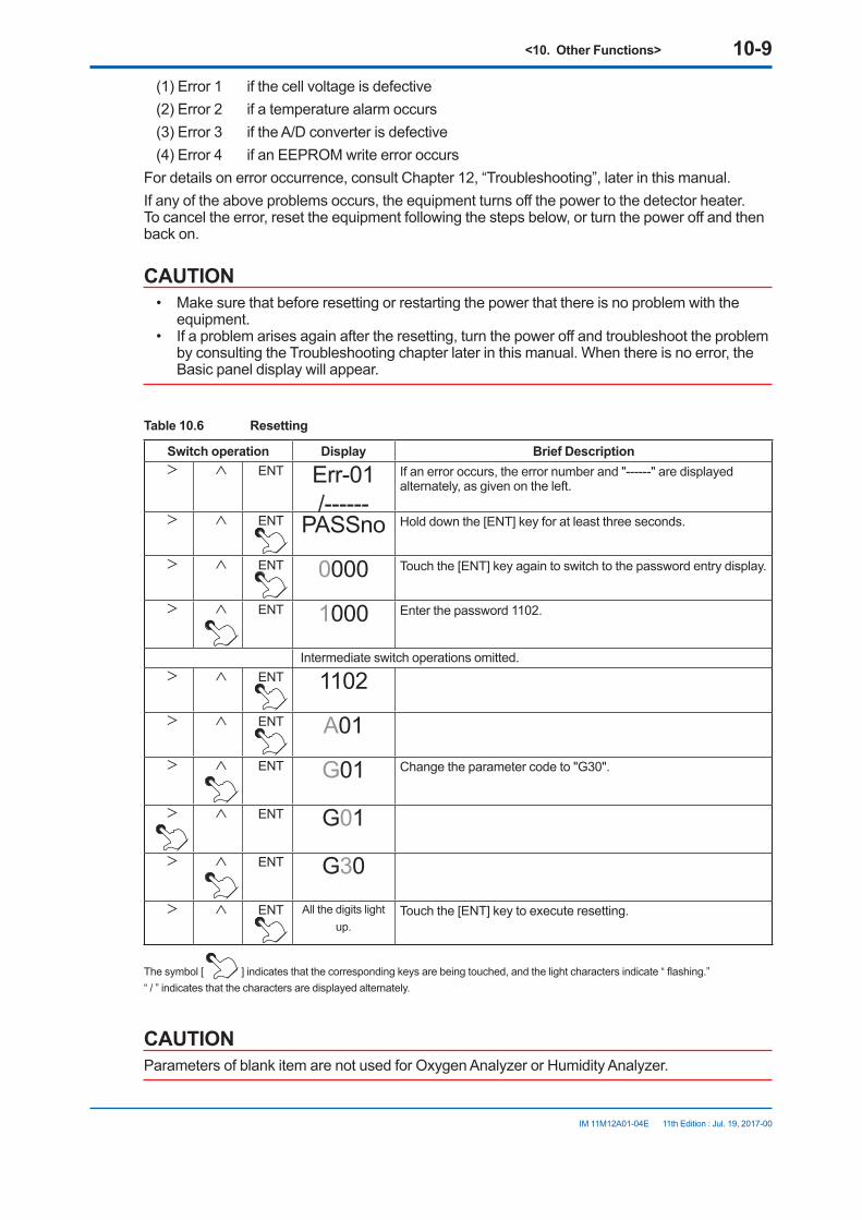
<10. Other Functions> 10-9
IM 11M12A01-04E 11th Edition : Jul. 19, 2017-00
(1) Error 1 if the cell voltage is defective(2) Error 2 if a temperature alarm occurs(3) Error 3 if the A/D converter is defective(4) Error 4 if an EEPROM write error occurs
For details on error occurrence, consult Chapter 12, “Troubleshooting”, later in this manual.If any of the above problems occurs, the equipment turns off the power to the detector heater. To cancel the error, reset the equipment following the steps below, or turn the power off and then back on.
CAUTION• Make sure that before resetting or restarting the power that there is no problem with the
equipment.• If a problem arises again after the resetting, turn the power off and troubleshoot the problem
by consulting the Troubleshooting chapter later in this manual. When there is no error, the Basic panel display will appear.
Table 10.6 Resetting
Switch operation Display Brief Description> ∧ ENT Err-01
/------If an error occurs, the error number and "------" are displayed alternately, as given on the left.
> ∧ ENT PASSno Hold down the [ENT] key for at least three seconds.
> ∧ ENT 0000 Touch the [ENT] key again to switch to the password entry display.
> ∧ ENT 1000 Enter the password 1102.
Intermediate switch operations omitted.> ∧ ENT 1102> ∧ ENT A01> ∧ ENT G01 Change the parameter code to "G30".
> ∧ ENT G01
> ∧ ENT G30
> ∧ ENT All the digits light up.
Touch the [ENT] key to execute resetting.
The symbol [ ] indicates that the corresponding keys are being touched, and the light characters indicate “ flashing.”“ / ” indicates that the characters are displayed alternately.
CAUTIONParameters of blank item are not used for Oxygen Analyzer or Humidity Analyzer.

<10. Other Functions> 10-10
IM 11M12A01-04E 11th Edition : Jul. 19, 2017-00
Table 10.7 Parameter Codes for Oxygen Analyzer
Display-related Items in Group A
Code Item Engineering unit Code Item Engineering
unitA00 Selection
of display items
0 Oxygen concentration A50 Span correction ratio 0 %1 Oxygen analyzer (0.0) A51 Span correction ratio 1 %2 Oxygen analyzer (0.0) A52 Span correction ratio 2 %3 Analog output selected A53 Span correction ratio 3 %
A01 Oxygen concentration % O2 A54 Span correction ratio 0 %A02 A55 Span correction ratio 3 %A03 A56 Span correction ratio 2 %A04 A57 Span correction ratio 1 %A05 A58 Span correction ratio 2 %A06 Air ratio A59 Span correction ratio 1 %A07 Cell temperature °C A60 Zero correction ratio 0 %A08 Cold junction temperature °C A61 Zero correction ratio 1 %A09 Meas. gas temperature °C A62 Zero correction ratio 2 %A10 Amount of water vapor in % exhaust
gas% A63 Zero correction ratio 3 %
A11 Cell voltage mV A64 Zero correction ratio 4 %A12 TC voltage mV A65 Zero correction ratio 5 %A15 Cold junction voltage mV A66 Zero correction ratio 6 %A16 Output current mA A67 Zero correction ratio 7 %A20 Cell response time Seconds A68 Zero correction ratio 8 %A21 Cell internal resistance Ω A69 Zero correction ratio 9 %A22 Cell robustness A70 Calibration history 0 YY.MM.DD/
HH.MMA23 Heater on-time ratio % A71 Calibration history 1 YY.MM.DD/
HH.MMA24 Oxygen concentration (with time
constant)% O2 A72 Calibration history 2 YY.MM.DD/
HH.MMA25 A73 Calibration history 3 YY.MM.DD/
HH.MMA26 A74 Calibration history 4 YY.MM.DD/
HH.MMA30 Max. oxygen concentration % O2 A75 Calibration history 5 YY.MM.DD/
HH.MMA31 Occurrence of maximum oxygen
concentrationYY.MM.DD/HH.MM
A76 Calibration history 6 YY.MM.DD/HH.MM
A32 Min. oxygen concentration % O2 A77 Calibration history 7 YY.MM.DD/HH.MM
A33 Occurrence of minimum oxygen concentration
YY.MM.DD/HH.MM
A78 Calibration history 8 YY.MM.DD/HH.MM
A34 Average oxygen concentration % O2 A79 Calibration history 9 YY.MM.DD/HH.MM
A35 A80 Time YY.MM.DD/HH.MM
A36 A90 Software revision
Note1: “/” indicates that both are displayed alternately.Note2: Parameter codes with no items in the above table are not used in the oxygen analyzer.

<10. Other Functions> 10-11
IM 11M12A01-04E 11th Edition : Jul. 19, 2017-00
Calibration-related Items in Group B
Code Item Tuning Engineering unit Default settingB01 Zero gas concentration 0.3 to 100 % O2 1% O2
B02 Span gas concentration 4.5 to 100 % O2 21% O2
B03 Calibration mode 0 Manual calibration Manual calibration1 Semi-automatic and manual
calibration2 Automatic, semi-automatic, and
manual calibrationB04 Hold (Output stabilization)
time 0 minutes, 0 seconds to 60 minutes, 59 seconds
MM.SS 10 minutes, 0 seconds
B05 Calibration time 0 minutes, 0 seconds to 60 minutes, 59 seconds
MM.SS 10 minutes, 0 seconds
B06 Calibration interval 0 days 0 hours to 255 days 23 hours DD.HH 30 days, 0 hoursB07 Calibration start date and
time YY.MM.DD/HH.MM
00.01.01.00.00
B08 Calibration procedure 0 Zero and span Zero and span1 Span only 2 Zero only
B09 Calibration concentration measurement
Display only % O2
B10 Manual calibration implementation
B11 Semi-automatic calibration implementation
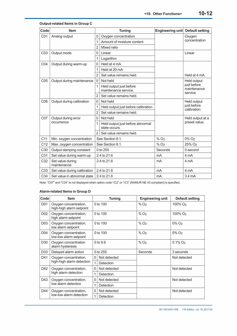
<10. Other Functions> 10-12
IM 11M12A01-04E 11th Edition : Jul. 19, 2017-00
Output-related Items in Group C
Code Item Tuning Engineering unit Default settingC01 Analog output 0 Oxygen concentration Oxygen
concentration1 Amount of moisture content2 Mixed ratio
C03 Output mode 0 Linear Linear1 Logarithm
C04 Output during warm-up 0 Held at 4 mA
Held at 4 mA.1 Held at 20 mA2 Set value remains held.
C05 Output during maintenance 0 Not held Held output just before maintenance service.
1 Held output just before maintenance service.
2 Set value remains held.C06 Output during calibration 0 Not held Held output
just before calibration.
1 Held output just before calibration.2 Set value remains held.
C07 Output during error occurrence
0 Not held Held output at a preset value.1 Held output just before abnormal
state occurs.2 Set value remains held.
C11 Min. oxygen concentration See Section 8.1. % O2 0% O2
C12 Max. oxygen concentration See Section 8.1. % O2 25% O2
C30 Output damping constant 0 to 255 Seconds 0 secondC31 Set value during warm-up 2.4 to 21.6 mA 4 mAC32 Set value during
maintenance2.4 to 21.6 mA 4 mA
C33 Set value during calibration 2.4 to 21.6 mA 4 mAC34 Set value in abnormal state 2.4 to 21.6 mA 3.4 mA
Note: “C07” and “C34” is not displayed when option code “/C2” or “/C3” (NAMUR NE 43 compliant) is specified.
Alarm-related Items in Group D
Code Item Tuning Engineering unit Default settingD01 Oxygen concentration,
high-high alarm setpoint0 to 100 % O2 100% O2
D02 Oxygen concentration, high alarm setpoint
0 to 100 % O2 100% O2
D03 Oxygen concentration, low alarm setpoint
0 to 100 % O2 0% O2
D04 Oxygen concentration, low-low alarm setpoint
0 to 100 % O2 0% O2
D30 Oxygen concentration alarm hysteresis
0 to 9.9 % O2 0.1% O2
D33 Delayed alarm action 0 to 255 Seconds 3 secondsD41 Oxygen concentration,
high-high alarm detection 0 Not detected Not detected1 Detection
D42 Oxygen concentration, high alarm detection
0 Not detected Not detected1 Detection
D43 Oxygen concentration, low alarm detection
0 Not detected Not detected1 Detection
D44 Oxygen concentration, low-low alarm detection
0 Not detected Not detected1 Detection

<10. Other Functions> 10-13
IM 11M12A01-04E 11th Edition : Jul. 19, 2017-00
Contact-related Items in Group E
Code Item Tuning Engineering unit Default settingE01 Selection of input contact 1 0 Invalid Invalid
1 Calibration gas pressure decrease2 Measurement range change3 Calibration start4 Detection of non-combusted gas
E02 Selection of input contact 2 0 Invalid Invalid1 Calibration gas pressure decrease2 Measurement range change3 Calibration start4 Detection of non-combusted gas
E03 Selecting action of input contact 1
0 Action with closed contact Action with closed contact1 Action with open contact
E04 Selecting action of input contact 2
0 Action with closed contact Action with closed contact1 Action with open contact
E10 Selecting action of output contact 1
0 Action with closed contact (normally energized)
Action with closed contact
1 Action with open contact (normally de-energized)
E20 Output contact 1 error 0 No action No action1 Action
E21 Output contact 1, high-high alarm
0 No action No action1 Action
E22 Output contact 1, high alarm
0 No action No action1 Action
E23 Output contact 1, low alarm 0 No action No action1 Action
E24 Output contact 1, low-low alarm
0 No action No action1 Action
E25 Output contact 1, during maintenance
0 No action Action1 Action
E26 Output contact 1, during calibration
0 No action No action1 Action
E27 Output contact 1, measurement range change
0 No action No action
1 Action
E28 Output contact 1, during warm up
0 No action Action1 Action
E29 Output contact 1, calibration gas pressure decrease
0 No action No action
1 Action
E32 Output contact 1, detection of non- combusted gas
0 No action No action
1 Action

<10. Other Functions> 10-14
IM 11M12A01-04E 11th Edition : Jul. 19, 2017-00
Equipment Setup and Others in Group F
Code Item Tuning Engineering unit Default settingF01
Equipment setup 0 Oxygen analyzer Oxygen analyzer1 Humidity analyzer
F02
Selection of measurement gas
0 Wet Wet1 Dry
F04
Selection of temperature units
0 degree C degree C1 degree F
F05
Selection of pressure units 0 kPa kPa1 psi
F08 Selection of display items 0 Oxygen concentration Oxygen concentration1 Amount of moisture quantity
2 Mixed ratio3 Item selected with analog output
F10
Date YY.MM.DD/HH.MM
F11 Period over which average values are calculated
1 to 255 hours Hours One hour
F12 Period over which max. and min. values are monitored
1 to 255 hours Hours 24 hours
F15 Purging time 0 to 60 minutes Minutes 0 minuteF20 Amount of water vapor in
exhaust gas 0 to 5 m3/kg (m3) 1.0 m3/kg (m3)
F21 Theoretical amount of air 0 to 20 m3/kg (m3) 1.0 m3/kg (m3)F22 X value 0 to 19.99 1F23 Absolute humidity of the
atmosphere0 to 1 kg/kg 0.1 kg/kg
F30 Initializing all dataF31 Initializing data in group AF32 Initializing data in group BF33 Initializing data in group CF34 Initializing data in group DF35 Initializing data in group EF36 Initializing data in group F
Inspection-related Items in Group G
Code Item Tuning Engineering unit Default settingG01 mA-output loop 4 to 20 mA 4 mAG11
Output contact 1 0 Open Open1 Closed
G12
Output contact 2 0 Open Open1 Closed
G15 Automatic calibration solenoid valve (zero)
0 Off Off1 On
G16 Automatic calibration solenoid valve (span)
0 Off Off1 On
G21
Input1 contact 0 Open1 Closed
G22
Input2 contact 0 Open1 Closed
G30 Reset

<10. Other Functions> 10-15
IM 11M12A01-04E 11th Edition : Jul. 19, 2017-00
Table 10.8 Parameter Codes for Humidity Analyzer
Display-related Items in Group A
Code Item Engineering unit Code Item Engineering
unitA00 Selection
of display items
0 Oxygen concentration A50 Span correction ratio 0 %1 Oxygen analyzer (0.0) A51 Span correction ratio 1 %2 Oxygen analyzer (0.0) A52 Span correction ratio 2 %3 Analog output selected A53 Span correction ratio 3 %
A01 Oxygen concentration % O2 A54 Span correction ratio 0 %A02 Humidity %H2O A55 Span correction ratio 3 %A03 Mixing ratio kg/kg A56 Span correction ratio 2 %A04 Relative humidity % A57 Span correction ratio 1 %A05 Dew point °C A58 Span correction ratio 2 %A06 A59 Span correction ratio 1 %A07 Cell temperature °C A60 Zero correction ratio 0 %A08 Cold junction temperature °C A61 Zero correction ratio 1 %A09 Meas. gas temperature °C A62 Zero correction ratio 2 %A10 A63 Zero correction ratio 3 %A11 Cell voltage mV A64 Zero correction ratio 4 %A12 TC voltage mV A65 Zero correction ratio 5 %A15 Cold junction voltage mV A66 Zero correction ratio 6 %A16 Output current mA A67 Zero correction ratio 7 %A20 Cell response time Seconds A68 Zero correction ratio 8 %A21 Cell internal resistance Ω A69 Zero correction ratio 9 %A22 Cell robustness kg/kg A70 Calibration history 0 YY.MM.DD/
HH.MMA23 Heater on-time ratio % A71 Calibration history 1 YY.MM.DD/
HH.MMA24 Oxygen concentration (with time
constant)% O2 A72 Calibration history 2 YY.MM.DD/
HH.MMA25 Humidity (with time /time constant) %H2O A73 Calibration history 3 YY.MM.DD/
HH.MMA26 Mixing ratio (with time /time constant) A74 Calibration history 4 YY.MM.DD/
HH.MMA30 Max. oxygen concentration % O2 A75 Calibration history 5 YY.MM.DD/
HH.MMA31 Occurrence of maximum oxygen
concentrationYY.MM.DD/HH.MM
A76 Calibration history 6 YY.MM.DD/HH.MM
A32 Min. oxygen concentration % O2 A77 Calibration history 7 YY.MM.DD/HH.MM
A33 Occurrence of minimum oxygen concentration
YY.MM.DD/HH.MM
A78 Calibration history 8 YY.MM.DD/HH.MM
A34 Average oxygen concentration % O2 A79 Calibration history 9 YY.MM.DD/HH.MM
A35 Maximum humidity %H2O A80 Time YY.MM.DD/HH.MM
A36 Occurrence of max. humidity YY.MM.DD/HH.MM
A90 Software revision
A37 Minimum humidity %H2OA38 Occurrence of min. humidity YY.MM.DD/
HH.MM A39 Average humidity %H2O

<10. Other Functions> 10-16
IM 11M12A01-04E 11th Edition : Jul. 19, 2017-00
A40 Maximum mixing ratio kg/kgA41 Occurrence of max. mixing ratio YY.MM.DD/
HH.MM A42 Minimum mixing ratio kg/kgA43 Occurrence of min. mixing ratio YY.MM.DD/
HH.MM A44 Average mixing ratio kg/kg
Note1: “/” indicates that both are displayed alternately.Note2: Parameter codes with no items in the above table are not used in the oxygen analyzer.
Calibration-related Items in Group B
Code Item Tuning Engineering unit Default settingB01 Zero gas concentration 0.3 to 100 % O2 1% O2
B02 Span gas concentration 4.5 to 100 % O2 21% O2
B03 Calibration mode 0 Manual calibration Manual calibration1 Semi-automatic and manual
calibration2 Automatic, semi-automatic, and
manual calibrationB04 Hold (Output stabilization)
time 0 minutes, 0 seconds to 60 minutes, 59 seconds
MM.SS 10 minutes, 0 seconds
B05 Calibration time 0 minutes, 0 seconds to 60 minutes, 59 seconds
MM.SS 10 minutes, 0 seconds
B06 Calibration interval 0 days 0 hours to 255 days 23 hours DD.HH 30 days, 0 hoursB07 Calibration start date and
time YY.MM.DD/HH.MM
00.01.01.00.00
B08 Calibration procedure 0 Zero and span Zero and span1 Span only 2 Zero only
B09 Calibration concentration measurement
Display only % O2
B10 Manual calibration implementation
B11 Semi-automatic calibration implementation

<10. Other Functions> 10-17
IM 11M12A01-04E 11th Edition : Jul. 19, 2017-00
Output-related Items in Group C
Code Item Tuning Engineering unit Default settingC01 Analog output 0 Oxygen concentration Humidity
1 Amount of moisture content2 Mixed ratio
C03 Output mode 0 Linear Linear1 Logarithm
C04 Output during warm-up 0 Held at 4 mA
Held at 4 mA.1 Held at 20 mA2 Set value remains held.
C05 Output during maintenance 0 Not held Held output just before maintenance service.
1 Held output just before maintenance service.
2 Set value remains held.C06 Output during calibration 0 Not held Held output
just before calibration.
1 Held output just before calibration.2 Set value remains held.
C07 Output during error occurrence
0 Not held Held output at a preset value.1 Held output just before abnormal
state occurs.2 Set value remains held.
C11 Min. oxygen concentration See Section 8.1. % O2 0% O2
C12 Max. oxygen concentration See Section 8.1. % O2 25% O2
C13 Minimum humidity See Section 8.1. %H2O 0 %H2OC14 Maximum humidity See Section 8.1. %H2O 25 %H2OC15 Minimum mixing ratio See Section 8.1. kg/kg 0 kg/kgC16 Maximum mixing ratio See Section 8.1. kg/kg 0.2 kg/kgC30 Output damping constant 0 to 255 Seconds 0 secondC31 Set value during warm-up 2.4 to 21.6 mA 4 mAC32 Set value during
maintenance2.4 to 21.6 mA 4 mA
C33 Set value during calibration 2.4 to 21.6 mA 4 mAC34 Set value in abnormal state 2.4 to 21.6 mA 3.4 mA
Note: “C07” and “C34” is not displayed when option code “/C2” or “/C3” (NAMUR NE 43 compliant) is specified.

<10. Other Functions> 10-18
IM 11M12A01-04E 11th Edition : Jul. 19, 2017-00
Alarm-related Items in Group D
Code Item Tuning Engineering unit Default settingD01 Oxygen concentration,
high-high alarm setpoint0 to 100 % O2 100% O2
D02 Oxygen concentration, high alarm setpoint
0 to 100 % O2 100% O2
D03 Oxygen concentration, low alarm setpoint
0 to 100 % O2 0% O2
D04 Oxygen concentration, low-low alarm setpoint
0 to 100 % O2 0% O2
D05 Humidity, high-high alarm setpoint
0 to 100 %H2O 100 %H2O
D06 Humidity, high alarm setpoint
0 to 100 %H2O 100 %H2O
D07 Humidity, low alarm setpoint
0 to 100 %H2O 0 %H2O
D08 Humidity, low-low alarm setpoint
0 to 100 %H2O 0 %H2O
D11 Mixing ratio, high-high alarm setpoint
0 to 1 kg/kg 1 kg/kg
D12 Mixing ratio, high alarm setpoint
0 to 1 kg/kg 1 kg/kg
D13 Mixing ratio, low alarm setpoint
0 to 1 kg/kg 0 kg/kg
D14 Mixing ratio, low-low alarm setpoint
0 to 1 kg/kg 0 kg/kg
D30 Oxygen concentration alarm hysteresis
0 to 9.9 % O2 0.1% O2
D31 Humidity alarm hysteresis 0 to 9.9 %H2O 0.1 %H2OD32 Mixing ratio alarm
hysteresis0 to 0.1 kg/kg 0.001 kg/kg
D33 Delayed alarm action 0 to 255 Seconds 3 secondsD41 Oxygen concentration,
high-high alarm detection 0 Not detected Not detected1 Detection
D42 Oxygen concentration, high alarm detection
0 Not detected Not detected1 Detection
D43 Oxygen concentration, low alarm detection
0 Not detected Not detected1 Detection
D44 Oxygen concentration, low-low alarm detection
0 Not detected Not detected1 Detection
D45 Humidity, high-high alarm detection
0 Not detected Not detected1 Detection
D46 Humidity, high alarm detection
0 Not detected Not detected1 Detection
D47 Humidity, low alarm detection
0 Not detected Not detected1 Detection
D48 Humidity, low-low alarm detection
0 Not detected Not detected1 Detection
D51 Mix ratio, high-high alarm detection
0 Not detected Not detected1 Detection
D52 Mix ratio, high alarm detection
0 Not detected Not detected1 Detection
D53 Mix ratio, low alarm detection
0 Not detected Not detected1 Detection

<10. Other Functions> 10-19
IM 11M12A01-04E 11th Edition : Jul. 19, 2017-00
D54 Mix ratio, low-low alarm detection
0 Not detected Not detected1 Detection
Contact-related Items in Group E
Code Item Tuning Engineering unit Default settingE01 Selection of input contact 1 0 Invalid Invalid
1 Calibration gas pressure decrease2 Measurement range change3 Calibration start4 Detection of non-combusted gas
E02 Selection of input contact 2 0 Invalid Invalid1 Calibration gas pressure decrease2 Measurement range change3 Calibration start4 Detection of non-combusted gas
E03 Selecting action of input contact 1
0 Action with closed contact Action with closed contact1 Action with open contact
E04 Selecting action of input contact 2
0 Action with closed contact Action with closed contact1 Action with open contact
E10 Selecting action of output contact 1
0 Action with closed contact (normally energized)
Action with closed contact
1 Action with open contact (normally de-energized)
E20 Output contact 1 error 0 No action No action1 Action
E21 Output contact 1, high-high alarm
0 No action No action1 Action
E22 Output contact 1, high alarm
0 No action No action1 Action
E23 Output contact 1, low alarm 0 No action No action1 Action
E24 Output contact 1, low-low alarm
0 No action No action1 Action
E25 Output contact 1, during maintenance
0 No action Action1 Action
E26 Output contact 1, during calibration
0 No action No action1 Action
E27 Output contact 1, measurement range change
0 No action No action
1 Action
E28 Output contact 1, during warm up
0 No action Action1 Action
E29 Output contact 1, calibration gas pressure decrease
0 No action No action
1 Action
E32 Output contact 1, detection of non- combusted gas
0 No action No action
1 Action

<10. Other Functions> 10-20
IM 11M12A01-04E 11th Edition : Jul. 19, 2017-00
Equipment Setup and Others in Group F
Code Item Tuning Engineering unit Default settingF01
Equipment setup 0 Oxygen analyzer Not initialized1 Humidity analyzer
F02 F04
Selection of temperature units
0 degree C degree C1 degree F
F05
Selection of pressure units 0 kPa kPa1 psi
F08 Selection of display items 0 Oxygen concentration Humidity1 Amount of moisture quantity2 Mixed ratio3 Item selected with analog output
F10
Date YY.MM.DD/HH.MM
F11 Period over which average values are calculated
1 to 255 hours Hours One hour
F12 Period over which max. and min. values are monitored
1 to 255 hours Hours 24 hours
F13 Process gas temperature 0 to 3000 °C 300°CF14 Process gas pressure 0 to 300 kPa abs. 101.33 kPa abs.F20 F21 F22 F23 F30 Initializing all dataF31 Initializing data in group AF32 Initializing data in group BF33 Initializing data in group CF34 Initializing data in group DF35 Initializing data in group EF36 Initializing data in group F
Inspection-related Items in Group G
Code Item Tuning Engineering unit Default settingG01 mA-output loop 4 to 20 mA 4 mAG11
Output contact 1 0 Open Open1 Closed
G12
Output contact 2 0 Open Open1 Closed
G15 Automatic calibration solenoid valve (zero)
0 Off Off1 On
G16 Automatic calibration solenoid valve (span)
0 Off Off1 On
G21
Input1 contact 0 Open1 Closed
G22
Input2 contact 0 Open1 Closed
G30 Reset

<10. Other Functions> 10-21
IM 11M12A01-04E 11th Edition : Jul. 19, 2017-00
10.5 Handling of the ZO21S Standard Gas UnitThe following describe how to flow zero and span gases using the ZO21S Standard Gas Unit. Operate the ZO21S Standard Gas Unit, for calibrating a system classified as System 1, according to the procedures that follow.
10.5.1 Standard Gas Unit Component Identification
Applies the power to operate the pump to supply the span gas.
Carrying case
Flow checker
Span gas valve
Checks the zero and span gas flow.
Controls the span gas (air) flow.
Zero gas valve regulator
Tube connectionCover screws (six pcs.)
PumpSupplies span gas (air)
Gas cylinderContains the zero gas. A gas of 7 Nl is charged to 700 kPa
ClampClamps the gas cylinder.
Zero gas valveAttaches to the gas cylinder for use.
Power cord
F10.14E.ai
Figure 10.4 Standard Gas Unit Component Identification
10.5.2 Installing Gas CylindersEach ZO21S Standard Gas Unit comes with six zero gas cylinders including a spare. Each gas cylinder contains 7-liters of gas with a 0.95 to 1.0 vol% O2 (concentration varies with each cylinder) and nitrogen, at a pressure of 700 kPaG (at 35°C).The operating details and handling precautions are also printed on the product. Please read them beforehand.
<10. Other Functions> 10-22
IM 11M12A01-04E 11th Edition : Jul. 19, 2017-00
To install the gas cylinder, follow these steps:(1) Attach the zero gas valves onto the gas cylinder. First, turn the valve regulator of the zero
gas valves counterclockwise to completely retract the needle at the top from the gasket surface. Maintaining the valve in this position, screw the valve mounting into the mouthpiece of the gas cylinder. (If screw connection is proper, you can turn the screw manually. Do not use any tool.) When the gasket comes in contact with the mouthpiece of the gas cylinder and you can no longer turn it manually, tighten the lock nut with a wrench.
(2) Remove the carrying case from the standard gas unit. The case is attached to the unit with six screws. So, loosen the screws and lift them off.
(3) Slide the gas cylinder through the hole in the back of the unit and connect the tube (the piping in the unit) to the valve connections. Insert each tube at least 10 mm to prevent leakage, and secure it using a tube clamp.
(4) Attach the gas cylinder to the case. Extend the valve regulator of the zero gas valves through the hole in the front panel of the unit and secure the bottom of the cylinder with the clamp.
(5) Take note of the oxygen concentration of the sealed gas indicated on the gas cylinder and replace the carrying case. Enter the oxygen concentration of the sealed gas using the parameter code B01 as a zero gas oxygen concentration. Also check that no piping is disconnected.
Thus, the work of installing a gas cylinder is completed. However, gases in the cylinders cannot immediately flow out after these procedures. To discharge the gases, it is necessary for the needle in the zero gas valves to puncture a hole in the gas cylinder (see Section 10.5.3).
10.5.3 Calibration Gas Flow<Preparation before calibration>
(1) To operate the standard gas unit, place it on a nearly horizontal surface in order to allow the flow check to indicate the precise flow rate. In addition, a power supply for driving the span gas (air) supply pump is required near the unit (the length of the power cord attached to the unit is 2 m). Select a suitable location for the unit near the installation site of the converter.
(2) Connect the tube connector port of the standard gas unit to the calibration gas inlet of the detector, using a polyethylene resin tube with an outside diameter of 6 mm. Be careful to prevent gas leakage.
(3) Fully open the stop valve mounted on the calibration gas inlet of the detector.(4) Enter the oxygen concentration of the sealed gas (noted from the cylinder) into the
converter. Also check that the oxygen concentration of the span gas is correctly set (21 vol% O2 for clean air). When using the ZO21S Standard Gas Unit (for use of the atmospheric air as a span gas), use a hand-held oxygen analyzer to measure the actual oxygen concentration, and then enter it.
<Flow of span gas (air)>The standard gas unit is used only when manual calibration is employed. Therefore, the timing for flowing span gas (air) is included in the manual calibration flowchart described in Section 7.11.2, earlier in this manual. For operation of the converter, see Section 7.11.2.
(1) When the “OPEn” and the “measured oxygen concentration” are alternately displayed during calibration, plug the power cord into the power supply socket to start the pump of the standard gas unit.
(2) Next, adjust the flow rate to 600 ± 60 ml/min using the span gas valve “AIR” (the flow check ball stops floating on the green line when the valve is slowly opened). To rotate the valve shaft, loosen the lock nut and turn it using a flat-blade screwdriver. Turning the valve shaft counterclockwise increases the flow rate.
(3) After adjusting the flow rate, tighten the valve lock nut.

<10. Other Functions> 10-23
IM 11M12A01-04E 11th Edition : Jul. 19, 2017-00
(4) After the measured oxygen concentration is stabilized, touch the [ENT] key, then all the digits flash. Touch the [ENT] key again to display “ZEro Y”. Disconnect the power cord to stop the pump.
<Flow of zero gas> Touch the [ENT] key to display a zero gas value set with the parameter code B01. Touch the [ENT] key again to flash “OPEn” and the “measured oxygen concentration” alternately. To cause the zero gas flow, follow these steps:
(1) Use the needle of the zero gas valve “CHECK GAS” to puncture a hole in the gas cylinder installed as described in Section 10.5.2. Fully clockwise turn the valve regulator by hand.
(2) Next, adjust the flow rate to 600 ± 60 ml/min (the flow check ball stops floating on the green line when the valve is slowly opened). Turn the regulator of the zero gas valve back slowly counterclockwise. At that time, the flow rate also decreases as the inner pressure of the gas cylinder decreases. Monitor the flow check and, when the ball’s position changes greatly, readjust the valve.
(3) Touch the [ENT] key after the measured oxygen concentration becomes stable. Then all the digits flash. Touch the [ENT] key again so that the “CALEnd” flashes.
NOTEBe sure not to terminate the calibration in progress because of a shortage of gas in the cylinder. Each gas cylinder is operable for nine minutes or more provided the gas is discharged at the specified rate.
Therefore, if your calibration time is estimated at four minutes, you can operate the zero calibration twice.
(4) Stop the zero gas flow. Turn the zero gas valve regulator fully clockwise. If this valve regulator is not properly adjusted, the needle valve will not close completely and a cylinder gas may leak. When the output stabilization time elapses, the calibration is complete.
<Treatment after completion of calibration>(1) Fully close the stop valve mounted on the calibration gas inlet of the detector.(2) Remove the tube connecting the detector to the standard gas unit.
WARNINGStore the standard gas unit with the gas cylinder mounted where the ambient temperature does not exceed 40°C. Otherwise, the gas cylinder may explode. Store the spare gas cylinders under the same condition.
10.6 Methods of Operating Valves in the ZA8F Flow Setting Unit
The ZA8F Flow Setting Unit is used as the calibration equipment for a system conforming to System 2. Calibration in such a system is to be manually operated. So, you have to operate the valve of the Flow Setting Unit each time calibration is made (starting and stopping the calibration gas flow and adjusting the flow rate). For the operation of the converter, refer to Section 7.11.
<10. Other Functions> 10-24
IM 11M12A01-04E 11th Edition : Jul. 19, 2017-00
10.6.1 Preparation Before CalibrationTo operate the ZA8F Flow Setting Unit, prepare for calibration as follows:
(1) Check for a complete closing of the zero gas flow setting valve in the unit and open the regulator valve for the zero gas cylinder until the secondary pressure is sample gas pressure plus approx. 50 kPa (or sample gas pressure plus approx. 150 kPa when a check valve is used, maximum pressure rating is 300 kPa ).
(2) Check that the oxygen concentration of the zero gas and span gas (instrument air 21 vol% O2) in the cylinder is set for the converter.
10.6.2 Operating the Span Gas Flow Setting ValveThe following description is given assuming that instrument air, the same as the reference gas, is used as the span gas. For more details, see Section 7.11.2, “Manual Calibration,” earlier in this manual.
(1) When “OPEn” and the “measured oxygen concentration” appear alternately during the span calibration, open the span gas flow setting valve of the flow setting unit and adjust the flow rate to 600 ± 60 ml/min. Loosen the lock nut if the valve shaft has a lock nut, and turn the valve regulator slowly counterclockwise. To check the flow rate, use the calibration flowmeter. If the sample gas pressure is extremely high, adjust the sample gas pressure to obtain pressures (listed in Table 10.9) ± 10%.
Table 10.9
Sample gas pressure, (kPa) 50 100 150 200 250Flow rate, (ml/min) 500 430 380 350 320
(2) Adjust the flow rate. After the measured oxygen concentration has stabilized, touch the [ENT] key, then all the digits will flash. Touch the [ENT] key again to display “ZEro Y.”
(3) Close the span gas flow setting valve to stop the span gas (air) flow. If the valve shaft has a lock nut, be sure to tighten the lock nut to prevent any leakage of span gas into the sensor during measurement.
10.6.3 Operating the Zero Gas Flow Setting ValveOperate the zero gas flow setting valve during zero calibration in the following procedures:
(1) When the “OPEn” and the “measured oxygen concentration” appear alternately during calibration, open the zero gas flow setting valve of the flow setting unit and adjust the flow rate to 600 ± 60 ml/min. To rotate the valve shaft, loosen the lock nut if the valve shaft has a lock nut and slowly turn it counterclockwise.
(2) To check the flow rate, use an appropriate calibration gas flowmeter. If the sample gas pressure is extremely high, adjust the sample gas pressure to obtain pressures (listed in Table 10.9) ± 10%.
(3) Adjust the flow rate. After the measured oxygen concentration is stabilized, touch the [ENT] key, then all the digits will flash. Touch the [ENT] key again to flash “CAL End.”
(4) Close the zero gas flow setting valve to stop the zero gas flow. Be sure to tighten the lock nut if the valve shaft has a lock nut to prevent any leakage of zero gas into the sensor during measurement. When the stabilization time elapses, the zero calibration will be complete.
10.6.4 Treatment After CalibrationNo special treatment of the instrument is needed after calibration. However, it is recommended that the pressure regulator for the zero gas cylinders be closed because calibration is not required so often.
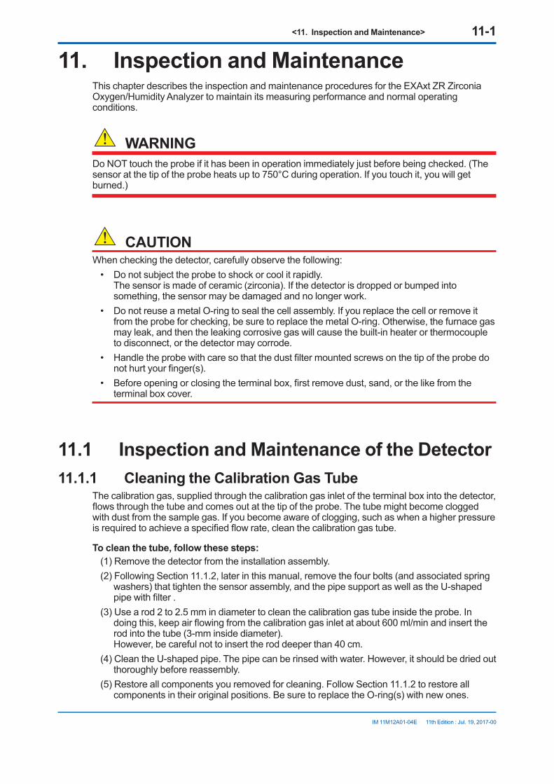
<11. Inspection and Maintenance> 11-1
IM 11M12A01-04E 11th Edition : Jul. 19, 2017-00
11. Inspection and MaintenanceThis chapter describes the inspection and maintenance procedures for the EXAxt ZR Zirconia Oxygen/Humidity Analyzer to maintain its measuring performance and normal operating conditions.
WARNINGDo NOT touch the probe if it has been in operation immediately just before being checked. (The sensor at the tip of the probe heats up to 750°C during operation. If you touch it, you will get burned.)
CAUTIONWhen checking the detector, carefully observe the following:
• Do not subject the probe to shock or cool it rapidly. The sensor is made of ceramic (zirconia). If the detector is dropped or bumped into something, the sensor may be damaged and no longer work.
• Do not reuse a metal O-ring to seal the cell assembly. If you replace the cell or remove it from the probe for checking, be sure to replace the metal O-ring. Otherwise, the furnace gas may leak, and then the leaking corrosive gas will cause the built-in heater or thermocouple to disconnect, or the detector may corrode.
• Handle the probe with care so that the dust filter mounted screws on the tip of the probe do not hurt your finger(s).
• Before opening or closing the terminal box, first remove dust, sand, or the like from the terminal box cover.
11.1 Inspection and Maintenance of the Detector11.1.1 Cleaning the Calibration Gas Tube
The calibration gas, supplied through the calibration gas inlet of the terminal box into the detector, flows through the tube and comes out at the tip of the probe. The tube might become clogged with dust from the sample gas. If you become aware of clogging, such as when a higher pressure is required to achieve a specified flow rate, clean the calibration gas tube.
To clean the tube, follow these steps:(1) Remove the detector from the installation assembly.(2) Following Section 11.1.2, later in this manual, remove the four bolts (and associated spring
washers) that tighten the sensor assembly, and the pipe support as well as the U-shaped pipe with filter .
(3) Use a rod 2 to 2.5 mm in diameter to clean the calibration gas tube inside the probe. In doing this, keep air flowing from the calibration gas inlet at about 600 ml/min and insert the rod into the tube (3-mm inside diameter). However, be careful not to insert the rod deeper than 40 cm.
(4) Clean the U-shaped pipe. The pipe can be rinsed with water. However, it should be dried out thoroughly before reassembly.
(5) Restore all components you removed for cleaning. Follow Section 11.1.2 to restore all components in their original positions. Be sure to replace the O-ring(s) with new ones.
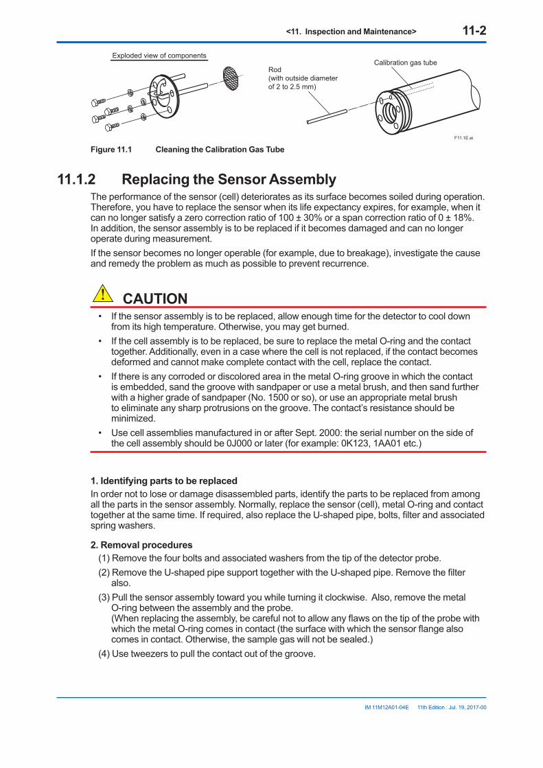
<11. Inspection and Maintenance> 11-2
IM 11M12A01-04E 11th Edition : Jul. 19, 2017-00
F11.1E.ai
Calibration gas tubeExploded view of components
Rod (with outside diameter of 2 to 2.5 mm)
Figure 11.1 Cleaning the Calibration Gas Tube
11.1.2 Replacing the Sensor AssemblyThe performance of the sensor (cell) deteriorates as its surface becomes soiled during operation. Therefore, you have to replace the sensor when its life expectancy expires, for example, when it can no longer satisfy a zero correction ratio of 100 ± 30% or a span correction ratio of 0 ± 18%. In addition, the sensor assembly is to be replaced if it becomes damaged and can no longer operate during measurement.If the sensor becomes no longer operable (for example, due to breakage), investigate the cause and remedy the problem as much as possible to prevent recurrence.
CAUTION• If the sensor assembly is to be replaced, allow enough time for the detector to cool down
from its high temperature. Otherwise, you may get burned. • If the cell assembly is to be replaced, be sure to replace the metal O-ring and the contact
together. Additionally, even in a case where the cell is not replaced, if the contact becomes deformed and cannot make complete contact with the cell, replace the contact.
• If there is any corroded or discolored area in the metal O-ring groove in which the contact is embedded, sand the groove with sandpaper or use a metal brush, and then sand further with a higher grade of sandpaper (No. 1500 or so), or use an appropriate metal brush to eliminate any sharp protrusions on the groove. The contact’s resistance should be minimized.
• Use cell assemblies manufactured in or after Sept. 2000: the serial number on the side of the cell assembly should be 0J000 or later (for example: 0K123, 1AA01 etc.)
1. Identifying parts to be replacedIn order not to lose or damage disassembled parts, identify the parts to be replaced from among all the parts in the sensor assembly. Normally, replace the sensor (cell), metal O-ring and contact together at the same time. If required, also replace the U-shaped pipe, bolts, filter and associated spring washers.
2. Removal procedures(1) Remove the four bolts and associated washers from the tip of the detector probe.(2) Remove the U-shaped pipe support together with the U-shaped pipe. Remove the filter
also.(3) Pull the sensor assembly toward you while turning it clockwise. Also, remove the metal
O-ring between the assembly and the probe. (When replacing the assembly, be careful not to allow any flaws on the tip of the probe with which the metal O-ring comes in contact (the surface with which the sensor flange also comes in contact. Otherwise, the sample gas will not be sealed.)
(4) Use tweezers to pull the contact out of the groove.
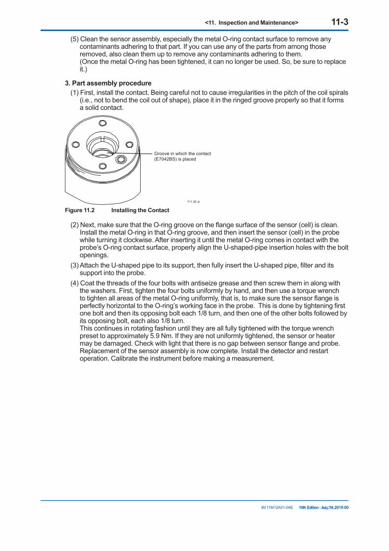
<11. Inspection and Maintenance> 11-3
IM 11M12A01-04E 11th Edition : Jul. 19, 2017-00
(5) Clean the sensor assembly, especially the metal O-ring contact surface to remove any contaminants adhering to that part. If you can use any of the parts from among those removed, also clean them up to remove any contaminants adhering to them. (Once the metal O-ring has been tightened, it can no longer be used. So, be sure to replace it.)
3. Part assembly procedure(1) First, install the contact. Being careful not to cause irregularities in the pitch of the coil spirals
(i.e., not to bend the coil out of shape), place it in the ringed groove properly so that it forms a solid contact.
Groove in which the contact(E7042BS) is placed
F11.2E.ai
Figure 11.2 Installing the Contact
(2) Next, make sure that the O-ring groove on the flange surface of the sensor (cell) is clean. Install the metal O-ring in that O-ring groove, and then insert the sensor (cell) in the probe while turning it clockwise. After inserting it until the metal O-ring comes in contact with the probe’s O-ring contact surface, properly align the U-shaped-pipe insertion holes with the bolt openings.
(3) Attach the U-shaped pipe to its support, then fully insert the U-shaped pipe, filter and its support into the probe.
(4) Coat the threads of the four bolts with antiseize grease and then screw them in along with the washers. First, tighten the four bolts uniformly by hand, and then use a torque wrench to tighten all areas of the metal O-ring uniformly, that is, to make sure the sensor flange is perfectly horizontal to the O-ring’s working face in the probe. This is done by tightening first one bolt and then its opposing bolt each 1/8 turn, and then one of the other bolts followed by its opposing bolt, each also 1/8 turn. This continues in rotating fashion until they are all fully tightened with the torque wrench preset to approximately 5.9 Nm. If they are not uniformly tightened, the sensor or heater may be damaged. Check with light that there is no gap between sensor flange and probe. Replacement of the sensor assembly is now complete. Install the detector and restart operation. Calibrate the instrument before making a measurement.
10th Edition : Aug.14,2015-00

<11. Inspection and Maintenance> 11-4
IM 11M12A01-04E 11th Edition : Jul. 19, 2017-00
F11.3E.ai
Dust filter (optional) Bolts (four)
Washers (four)
Sensor (cell)
U-shaped pipe
Metal O-ring
ContactProbe
1/8 turn – tighten bolts 1/8 turn (approximately 45°) each
U-shaped pipe support
Filter
Figure 11.3 Exploded View of Sensor Assembly
NOTEOptional Inconel bolts have a high coefficient of expansion. If excess torque is applied while the bolts are being tightened, abnormal strain or bolt breakage may result. So, tighten the bolts following the instructions given above.
11.1.3 Replacement of the Heater AssemblyThis section describes the replacement procedure for the heater assembly.The sensor or ceramic heater-furnace core internal structure is subject to fracturing, so do NOT subject it to strong vibrations or shock. Additionally, the heater assembly reaches high temperatures and is subjected to high voltages. So, maintenance services should be performed after the power is off and the heater assembly temperature has returned to normal room temperature.For details, refer to IM 11M12A01-21E “ Heater Assembly “.
NOTEIf the heater assembly can not be removed because a screw for the heater assembly fixation has fused to its thread, one of our service representatives can fix it.
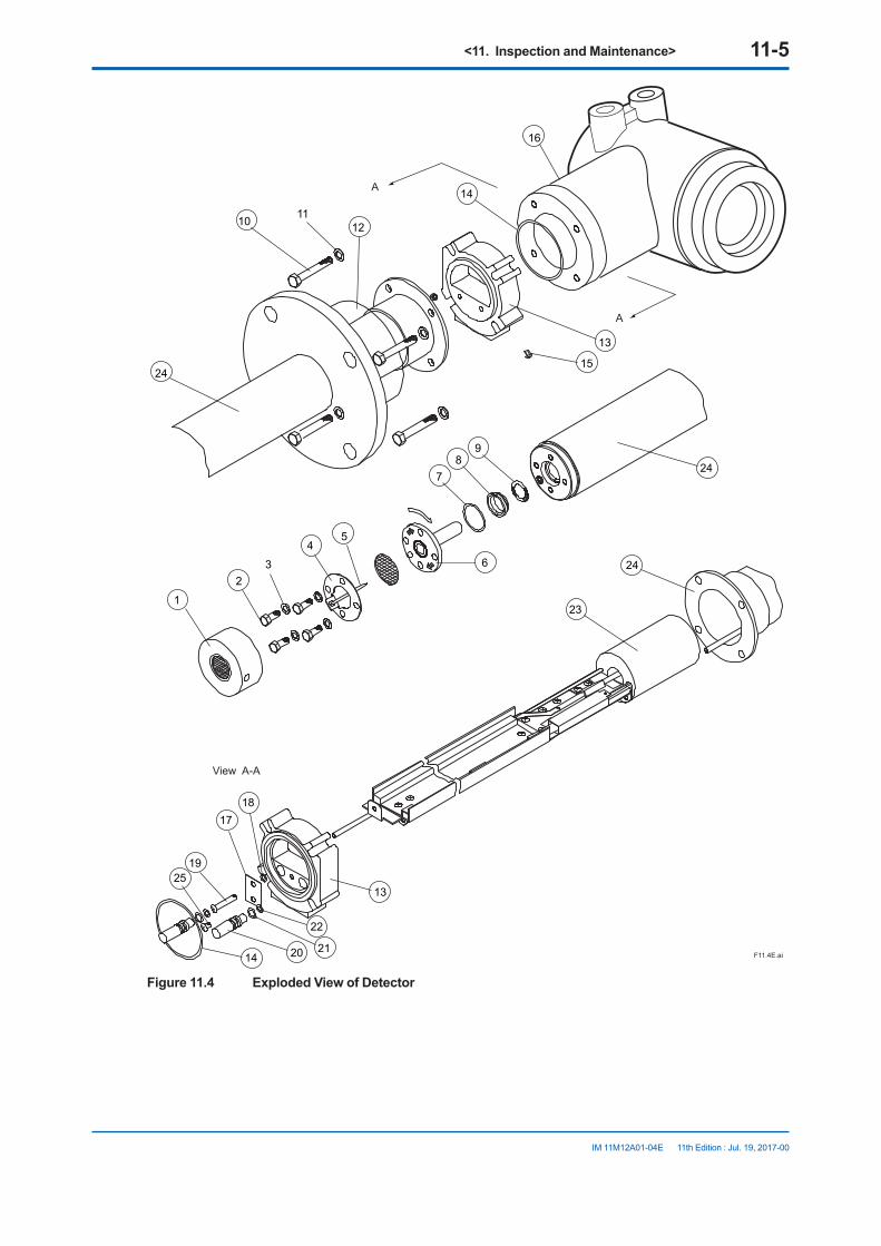
<11. Inspection and Maintenance> 11-5
IM 11M12A01-04E 11th Edition : Jul. 19, 2017-00
A
A
View A-A
25
1
23
45
6
78
9
10 1112
13
14
15
16
14
13
1718
19
20 21
22
23
24
24
24
F11.4E.ai
Figure 11.4 Exploded View of Detector
<11. Inspection and Maintenance> 11-6
IM 11M12A01-04E 11th Edition : Jul. 19, 2017-00
Replacement of heater assemblyRefer to Figure 11.4 as an aid in the following discussion.Remove U-shaped pipe support 4 , U-shaped pipe 5 , Filter and the sensor (cell) 6 , following Section 11.1.2, earlier in this manual. Remove the two screws 15 that tighten the cover 12 and slide it to the flange side. Remove the four bolts 10 to remove the converter 16 . Then remove the three connectors to which leadwire from the heater and thermocouple is connected. Loosen screw 19 until heater assembly 23 plate can be removed. There’s no need to remove O-ring 18 which prevents screw 19 from dropping out. Pull out connector 13 . Loosen and remove the screw for the heater assembly fixation 8 with a special wrench (part no. K9470BX or equivalent) and then remove the heater assembly 23 from the detector 24 .To reassemble the heater assembly, reverse the above procedure:Insert the heater assembly 23 into the detector 24 , while inserting the calibration pipe in the detector 24 into the heater section in the heater assembly 23 as well as in the bracket hole. Coat the screw for the heater assembly fixation 8 with grease (Never-Seez: G7067ZA) and tighten the screw for the heater assembly fixation 8 with a special tool (part no. K9470BX or equivalent) with a tightening torque of 12N·m ± 10%.Next, to install the O-rings 22 on the calibration-gas and reference-gas pipes, disassemble the connector 13 in the following procedure:First, remove the screw 25 and then remove the plate 17 and two caps 20 . If the O-ring 22 remains in the hole, pull them out from the back. Pass the heater and thermocouple leadwire through the connector 13 . Also, pass the calibration gas and reference gas pipes through the opening of the connector 13 . If the O-ring 22 fails, replace it with a new one.Push the two caps 20 into the associated opening of the connector 13 . Insert the plate 17 , aligning it with the groove of the cap 20 , and tighten it with the screw 25 . If you attempt to insert the calibration gas and reference gas pipes into the connector 13 without disassembling the connector 13 , the O-ring may be damaged. Tighten screw 19 in the heater assembly 23 until connector 13 can’t move.Reassemble in reverse order to the above disassembly procedure.When installing the cell assembly 6 , replace the metal O-ring 7 with a new one.
11.1.4 Replacement of Dust FilterSet the dust filter 1 in place using a special pin spanner (with a pin 4.5 mm in diameter: part no. K9471UX or equivalent). If a dust filter that has already been replaced once is used again, apply grease (Never-Seez: G7067ZA) to the threads of the dust filter.
11.1.5 Replacement of O-ringThe detector uses three different types of O-rings 14 , 24 , and 22 . One O-ring alone 14 , or two O-rings 21 and 22 are used. (For a pressure compensating model, two O-rings are used for individual uses. Two O-rings 21 and 22 are used for reference gas sealing and require periodic replacement.
Part No. Description(7) K9470BJ Metal O-ring(14) K9470ZS O-ring with grease(21)(22) K9470ZP Two pairs of O-rings with grease

<11. Inspection and Maintenance> 11-7
IM 11M12A01-04E 11th Edition : Jul. 19, 2017-00
11.1.6 Stopping and Re-starting Operation<Stopping Operation>When operation is stopped, take care of the followings so that the sensor of the detector cannot become unused.
CAUTIONWhen operating an instrument such as boiler or industrial furnace is stopped with the zirconia oxygen analyzer operation, moisture can condensate on the sensor portion and dusts may stick to it.If operation is restarted in this condition, the sensor which is heated up to 750°C firmly fixes the dusts on itself. Consequently, the dusts can make the sensor performance very lower. If a large amount of water is condensed, the sensor can be broken and never be used.To prevent the above nonconformity, take the following action when stopping operation.
(1) If possible, keep on supplying the power to converter and flowing reference gas to the sensor. If impossible to do the above, remove the detector.
(2) If unavoidably impossible to supply the power and removing the detector, keep on following air at 600 ml/min into the calibration gas pipe.
<Restarting Operation>When restarting operation, be sure to flow air, for 5-10 minutes, at 600 ml/min into the calibration gas pipe before supplying the power to converter.
11.2 Inspection and Maintenance of the Converter
The converter does not require routine inspection and maintenance. If the converter does not work properly, in most cases it probably comes from problems or other causes.
n Replacing FusesThis equipment incorporates a fuse. If the fuse blows out, turn off the equipment power and replace it in the following procedure.
CAUTIONIf a replaced fuse blows out immediately, there may be a problem in the circuit. Check the circuit carefully to find out why the fuse has blown.Before removing the electronics, touch the grounded metal part to discharge any static electricity.
(1) Remove the display cover (Figure 11.5).(2) Remove the three screws that are located toward you, among the four screws shown in
Figure 11.6. Loosen the remaining one.(3) Move the electronics up to remove it.
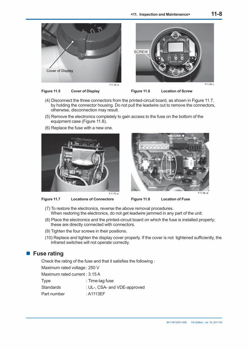
<11. Inspection and Maintenance> 11-8
IM 11M12A01-04E 11th Edition : Jul. 19, 2017-00
F11.5E.ai
Cover of Display
F11.6E.ai
SCREW
Figure 11.5 Cover of Display Figure 11.6 Location of Screw
(4) Disconnect the three connectors from the printed-circuit board, as shown in Figure 11.7, by holding the connector housing. Do not pull the leadwire out to remove the connectors, otherwise, disconnection may result.
(5) Remove the electronics completely to gain access to the fuse on the bottom of the equipment case (Figure 11.8).
(6) Replace the fuse with a new one.
F11.7E.ai F11.8E.ai
Figure 11.7 Locations of Connectors Figure 11.8 Location of Fuse
(7) To restore the electronics, reverse the above removal procedures. When restoring the electronics, do not get leadwire jammed in any part of the unit.
(8) Place the electronics and the printed-circuit board on which the fuse is installed properly; these are directly connected with connectors.
(9) Tighten the four screws in their positions.(10) Replace and tighten the display cover properly. If the cover is not tightened sufficiently, the
infrared switches will not operate correctly.
n Fuse ratingCheck the rating of the fuse and that it satisfies the following :Maximum rated voltage : 250 VMaximum rated current : 3.15 AType : Time-lag fuseStandards : UL-, CSA- and VDE-approvedPart number : A1113EF
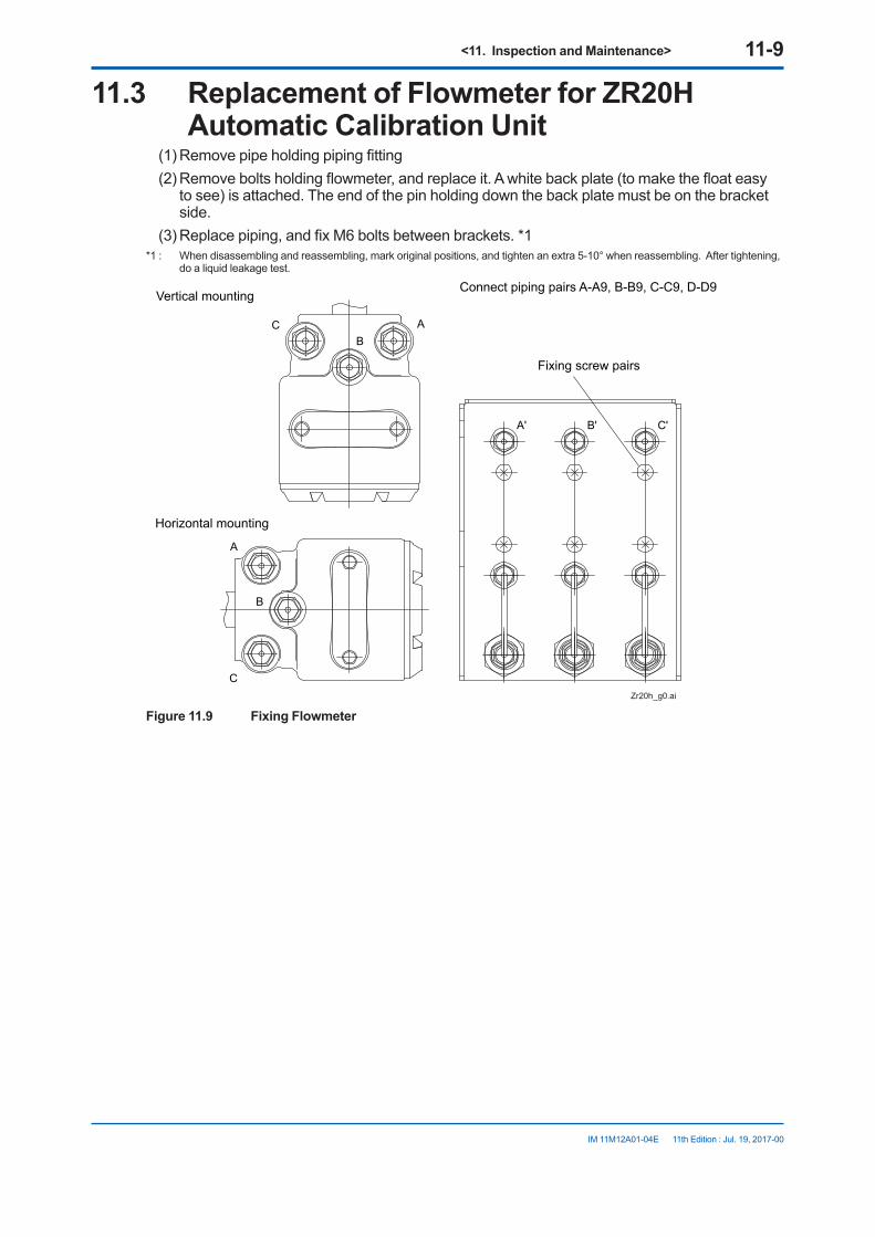
<11. Inspection and Maintenance> 11-9
IM 11M12A01-04E 11th Edition : Jul. 19, 2017-00
11.3 Replacement of Flowmeter for ZR20H Automatic Calibration Unit
(1) Remove pipe holding piping fitting (2) Remove bolts holding flowmeter, and replace it. A white back plate (to make the float easy
to see) is attached. The end of the pin holding down the back plate must be on the bracket side.
(3) Replace piping, and fix M6 bolts between brackets. *1 *1 : When disassembling and reassembling, mark original positions, and tighten an extra 5-10° when reassembling. After tightening,
do a liquid leakage test.
Vertical mounting
Horizontal mounting
C
C
B
B
C'B'A'
A
A
Zr20h_g0.ai
Connect piping pairs A-A9, B-B9, C-C9, D-D9
Fixing screw pairs
Figure 11.9 Fixing Flowmeter

Blank Page

<12. Troubleshooting> 12-1
IM 11M12A01-04E 11th Edition : Jul. 19, 2017-00
12. TroubleshootingThis chapter describes errors and alarms detected by the self-diagnostic function of the converter. This chapter also describes the check and restoration methods to use when problems other than the above occur.
12.1 Displays and Measures to Take When Errors Occur
12.1.1 What is an Error?An error is detected if any abnormality is generated in the detector or the converter, e.g., in the cell (sensor) or heater in the detector, or the internal circuits in the converter. If an error occurs, the converter performs the following:
(1) Stops the supply of power to the heater in the detector to insure system safety.(2) Causes an error indication in the display to start blinking to notify of an error generation
(Figure 12.1).(3) Sends an output contact if the error is set up for “Output contact setup” for that contact (refer
to Section 8.4, “Output Contact Setup”).(4) Changes the analog output status to the one set in “Output hold setting” (refer to Section
8.2, “Output Hold Setting”). When the display shown in Figure 12.1 appears, pressing the error indication brings up a description of the error (Figure 12.2). The content of errors that are displayed include those shown in Table 12.1.
Displayed alternately
Err-01 ---------F12.1E.ai
Figure 12.1
Table 12.1 Types of Errors and Reasons for Occurrence
Error Type of error Reason for OccurrenceError-1 Cell voltage failure The cell (sensor) voltage signal input to the converter falls below -50 mV.Error-2 Heater temperature
failureThe heater temperature does not rise during warm-up, or it falls below 730 °C or exceeds 780 °C after warm-up is completed.
Error-3 A/D converter failure The A/D converter fails in the internal electrical circuit in the converter.Error-4 Memory failure Data properly are not written into memory in the internal electrical circuit
in the converter.

<12. Troubleshooting> 12-2
IM 11M12A01-04E 11th Edition : Jul. 19, 2017-00
12.1.2 Measures to Take When an Error Occurs
n Error-1: Cell Voltage FailureError-1 occurs when the cell (sensor) voltage input to the converter falls below -50 mV (corresponding to about 200% O2). The following are considered to be the causes for the cell voltage falling below -50 mV:
(1) Continuity failure between the cell assembly electrode and the contact (2) Damage or deterioration of the cell assembly(3) Improper connection between the sensor and the electronics.(4) Wiring failure inside the detector (5) Abnormality in the converter electronics
<Locating the failure and Take measures>1) Turn off the power to the equipment.2) Remove the cell assembly from the probe. Check for dirty or corroded sensor parts,
including electrode and contact. 3) If the contact part is normal, the cell assembly may be damaged or deteriorated. Replace the
cell assembly. In this case, be sure to replace the metal O-ring and contact. 4) If Error-1 still occurs, check that the sensor and the electronics are properly connected. 5) Remove the probe to gain access to the two connectors (four connectors for the optional
automatic calibration unit), as indicated in Figure 12.2. Check these connectors are properly connected.
6) If Error-1 still occurs, the electronics may be defective. Contact your local Yokogawa service or sales representative.
n Error-2: Heater Temperature FailureThis error occurs if the detector heater temperature does not rise during warm-up, or if the temperature falls below 730°C or exceeds 780°C after warm-up is completed. Causes considered for cases where Error-2 occurs independently are shown below.
(1) Faulty heater in the probe (heater wire breakage)(2) Faulty thermocouple in the probe(3) Failure in the converter electronics
<Search for cause of failure and Take measures>(1) Turn off the power to the analyzer.(2) Remove the probe from the analyzer. Also remove all the connectors between the converter
and probe. Measure the resistance of the heater wire (yellow wire) from the probe as indicated in Figure 12.2. The heater assembly is normal if the resistance is lower than about 90Ω. If the resistance is higher than that value, the heater assembly may be defective. In this case, replace the heater assembly (refer to Section 11.1.3, “Replacement of the Heater Assembly”).
F12.2E.ai
Multimeter (Ω)
Heater wire
Figure 12.2

<12. Troubleshooting> 12-3
IM 11M12A01-04E 11th Edition : Jul. 19, 2017-00
(3) Next, check the resistance of the thermocouple from the probe. Use a multimeter to measure the thermocouple resistance between terminal 3 (red cable connected) and terminal 4 (white cable connected) as indicated in Figure 12.3.
The thermocouple is normal if the resistance is 5Ω or less. If the value is higher than 5Ω, the thermocouple wire may be broken or about to break. In this case, replace the heater assembly (refer to Section 11.1.3, “Replacement of the Heater Assembly”).
CAUTION Measure the thermocouple resistance value after the difference between the probe tip temperature and the ambient temperature decreases to 50°C or less. If the thermocouple voltage is large, accurate measurement cannot be achieved.
F12.3E.ai
1234
YELGRNREDWHT
Thermocouple Multimeter (Ω)
Figure 12.3
(4) If the inspection indicates that the thermocouple is normal, the electronics may be defective. Consult your local Yokogawa service or sales representative.
n Error-3: A/D Converter Failure/Error-4: Writing-to-memory Failure• A/D Converter Failure
It is suspected that a failure has occurred in the A/D converter mounted in the converter electronics.
• Writing-to-memory Failure It is suspected that a failure has occurred in an operation writing to the memory (EEPROM) mounted in the converter electronics.
<Locating the failure and take measures>Turn off the power to the converter once and then restart the converter. If the converter operates normally after restarting, an error might have occurred due to a temporary drop in the voltage (falling below 85 V, the least amount of voltage required to operate the converter) or a malfunction of the electronics affected by noise. Check whether or not there is a failure in the power supply system or whether the converter and detector are securely grounded.If the error occurs again after restarting, a failure in the electronics is suspected. Consult the service personnel at Yokogawa Electric Corporation.

<12. Troubleshooting> 12-4
IM 11M12A01-04E 11th Edition : Jul. 19, 2017-00
12.2 Displays and Measures to Take When Alarms are Generated
12.2.1 What is an Alarm?When an alarm is generated, the alarm indication blinks in the display to notify of the alarm (Figure 12.3).Pressing the alarm indication displays a description of the alarm. Alarms include those shown in Table 12.2.
Displayed alternately
AL-06 21.0%F12.4E.ai
Figure 12.4
Table 12.2 Types of Alarms and Reasons for Occurrence
Alarm Type of alarm Reason for occurrenceAlarm 1 through 3
Oxygen concentration alarmconcentration alarm humidity, and mixing ratio alarms
Occurs when a measured value exceed or falls below the set alarm value (refer to Section 8.3, "Setting Alarms").
Alarm 6 Zero calibration coefficient alarm Generated when the zero correction ratio is out of the range of 100 ± 30% in automatic and semi-automatic calibration (refer to Section 9.1.4, Compensation).
Alarm 7 Span calibration coefficient alarm Generated when the span correction ratio is out of the range of 0 ± 18% in automatic and semi-automatic calibration (refer to Section 9.1.4, "Compensation").
Alarm 8 EMF stabilization time-up Generated when the cell (sensor) voltage is not stabilized even after the calibration time is up in automatic and semi-automatic calibration.
Alarm 10 Cold junction temperature alarm Occurs when an equipment internal temperatureexceeds 85°C.
Alarm 11 Thermocouple voltage alarm Generated when thermocouple voltage exceeds 42.1 mV (about 1020°C ) or falls below -5 mV (about -170°C).
Alarm 13 Battery low alarm Internal battery needs replacement
If an alarm is generated, such measures as turning off the heater power are not carried out. The alarm is released when the cause for the alarm is eliminated. However, Alarm 10 and/or Alarm 11 may be generated at the same time as Error-2 (heater temperature error). In such a case, the measure taken for this error has priority.If the converter power is turned off after an alarm is generated and restarted before the cause of the alarm has been eliminated, the alarm will be generated again. However, Alarms 6, 7, and 8 (alarms related to calibration) are not generated unless calibration is executed.
12.2.2 Measures Taken When Alarms are Generated
l Alarm 1 through 3: Oxygen Concentration Alarm, Humidity, and Mixing Ratio AlarmsThis alarm is generated when a measured value exceeds an alarm set point or falls below it. For details on the oxygen concentration alarm, see Section 8.3, “Setting Alarms,” in the chapter on operation.

<12. Troubleshooting> 12-5
IM 11M12A01-04E 11th Edition : Jul. 19, 2017-00
l Alarm 6: Zero Calibration Coefficient AlarmIn calibration, this alarm is generated when the zero correction ratio is out of the range of 100 ± 30% (refer to Section 9.1.4, “Compensation”). The following can be considered the causes for this:
(1) The zero gas oxygen concentration does not agree with the value of the zero gas concentration set (refer to Section 9.2,“Calibration Procedures.)” Otherwise, the span gas is used as the zero gas.
(2) The zero gas flow is out of the specified flow (600 ± 60 ml/min).(3) The sensor assembly is damaged and so cell voltage is not normal.
<Search for cause of failure and Take measures>(1) Confirm the following and carry out calibration again: If the items are not within their proper
states, correct them. a. If the indication for “Zero gas conc.” is selected in “Calibration setup,” the set value should agree with the concentration of zero gas actually used. b. The calibration gas tubing should be constructed so that the zero gas does not leak.
(2) If no alarm is generated as a result of carrying out re-calibration, it is suspected that improper calibration conditions were the cause of the alarm in the preceding calibration. In this case, no specific restoration is necessary.
(3) If an alarm is generated again as a result of carrying out re-calibration, deterioration of or damage to the cell (sensor) is suspected as the cause of the alarm. Replacement of the cell (sensor) with a new one is necessary. However, before replacement, carry out the following: Check the cell voltages when passing the zero gas and span gas. a. Display the cell voltage with the parameter code A11. b. Check whether or not the value of the displayed cell voltage is very different from the
theoretical value at each oxygen concentration. Confirm the theoretical values of the cell voltage in Table 12.3. Although it cannot be generally specified as to what extent the difference from the theoretical value is allowed, consider it to be approximately ±10 mV.
Table 12.3 Oxygen Concentration and Cell Voltage Oxygen concentration
Oxygen concentration (% O2) Cell voltage (mV)1% 67.121% 0
(4) Confirm whether deterioration of or damage to the sensor assembly that caused the alarm has occurred abruptly during the current calibration in the following procedure: Check the history of the span gas correction ratio with the parameter codes A50 through A59, Check the history of the zero gas correction ratio with the parameter codes A60 through A69. The larger the parameter code number, the older the displayed data. Changes in deterioration of the sensor can be seen.
(5) If deterioration of the cell assembly has occurred abruptly, it may show that the check valve, which prevents moisture in the furnace from getting into the calibration gas tubing, has failed. If the gas in the furnace gets into the calibration gas tubing, it condenses and remains in the gas tubing. The cell assembly is considered to be broken for the reason that the condensation is blown into the cell assembly by the calibration gas during calibration and so the cell cools quickly.
(6) If the cell assembly has been gradually deteriorating, check the cell assembly status in the following procedure: a. Display “Cell resistance” by specifying the parameter code A21. A new cell will show
a cell resistance value of 200Ω or less. On the other hand, a cell (sensor) that is approaching the end of its service life will show a resistance value of 3 to 10 kΩ.
b. Display “Cell robustness” by specifying the parameter code A22. A good cell (sensor) will show “5,” “Life > 1 year” (refer to Section 10.1.17).
<12. Troubleshooting> 12-6
IM 11M12A01-04E 11th Edition : Jul. 19, 2017-00
l Alarm 7: Span Calibration Coefficient AlarmIn calibration, this alarm is generated when the span gas correction ratio is out of the range of 0 ± 18% (refer to Section 9.1.4, “Compensation”). The following are suspected as the cause:
(1) The oxygen concentration of the span gas does not agree with the value of the span gas set “Calibration setup.”
(2) The flow of the span gas is out of the specified flow value (600 ± 60 ml/min).(3) The cell assembly is damaged and the cell voltage is abnormal.
<Search for cause of failure and Take measures>(1) Confirm the following and carry out calibration again:
If the items are not within their proper states, correct them. a. If the display “Span gas conc.” is selected in “Calibration setup,” the set value should agree with the concentration of span gas actually used. b. The calibration gas tubing should be constructed so that the span gas does not leak.
(2) If no alarm is generated as a result of carrying out re-calibration, it is suspected that improper calibration conditions were the cause of the alarm in the preceding calibration. In this case, no specific restoration is necessary.
(3) If an alarm is generated again as a result of carrying out re-calibration, deterioration of or damage to the cell (sensor) is suspected as the cause of the alarm. Replacement of the cell with a new one is necessary. However, before replacement, carry out the procedure described in step (3) and later of <Search for cause of failure and taking measure> in Section 12.2.2.2, “Alarm 6: Zero Calibration Coefficient Alarm.”
l Alarm 8: EMF Stabilization Time OverThis alarm is generated if the sensor (cell) voltage has not stabilized even after the calibration time is up for the reason that the calibration gas (zero gas or span gas) has not filled the sensor assembly of the detector.
<Cause of alarm>(1) The flow of the calibration gas is less than normal (a specified flow of 600 ± 60 ml/min).(2) The length or thickness of the calibration gas tubing has been changed (lengthened or
thickened).(3) The measuring gas flows toward the tip of the probe.(4) The sensor (cell) response has deteriorated.
<Search for cause of failure and Take measures>(1) Carry out calibration by passing the calibration gas at the specified flow (600 ± 60 ml/min)
after checking that there is no leakage in the tubing.(2) If calibration is carried out normally, perform a steady operation without changing the
conditions. If the error occurs again, check whether or not the reason is applicable to the following and then replace the sensor assembly.
• A lot of dust and the like may be sticking to the tip of the sensor. If dust is found, clean and remove the dust (see Section 11.1.1).
In addition, if an error occurs in calibration even after the cell assembly is replaced, the influence of sample gas flow may be suspected. Do not let the sample gas flow toward the tip of the detector probe, for example, by changing the mounting position of the detector.
l Alarm 10: Cold Junction Temperature AlarmThe equipment incorporates a temperature sensor. An alarm is issued when the sensor temperature exceeds 85°C. If internal temperature of this equipment exceeds 85°C, the electronics may fail.

<12. Troubleshooting> 12-7
IM 11M12A01-04E 11th Edition : Jul. 19, 2017-00
<Search for cause of failure and Take measures>This equipment can be used at ambient temperatures up to 55°C. If the ambient temperatures may exceed the limits, take appropriate measures such as applying heat insulating material to the furnace walls, and adding a sun shield to keep out direct sunlight. If this alarm occurs even when the ambient temperature is under 55°C, the electronics may be defective. Contact your local Yokogawa service or sales representative.
l Alarm 11: Thermocouple Voltage AlarmThis alarm is generated when the emf (voltage) of thermocouple falls below -5 mV (about -170°C) or exceeds 42.1 mV (about 1020°C).
(1) A failure of the thermocouple at the detector occurred.(2) A failure of the electrical circuits occurred.
<Search for cause of failure and Take measures>(1) Turn off the power to the analyzer.(2) Remove the probe from the analyzer. Also remove all the connectors between the converter
and probe. Measure the resistance of the heater wire (yellow wire) from the probe as indicated in Figure 12.5. The heater assembly is normal if the resistance is lower than about 90Ω. If the resistance is higher than that value, the heater assembly may be defective. In this case, replace the heater assembly (refer to Section 11.1.3, “Replacement of the Heater Assembly”).
F12.2E.ai
Multimeter (Ω)
Heater wire
Figure 12.5
(3) Next, check the resistance of the thermocouple from the probe. Use a multimeter to measure the thermocouple resistance between terminal 3 (red cable connected) and terminal 4 (white cable connected) as indicated in Figure 12.6.
The thermocouple is normal if the resistance is 5Ω or less. If the value is higher than 5Ω, the thermocouple wire may be broken or about to break. In this case, replace the heater assembly (refer to Section 11.1.3, “Replacement of the Heater Assembly”).
CAUTIONMeasure the thermocouple resistance value after the difference between the probe tip temperature and the ambient temperature decreases to 50°C or less. If the thermocouple voltage is large, accurate measurement cannot be achieved.
F12.3E.ai
1234
YELGRNREDWHT
Thermocouple Multimeter (Ω)
Figure 12.6
(4) If the inspection indicates that the thermocouple is normal, the electronics may be defective. Consult your local Yokogawa service or sales representative.
<12. Troubleshooting> 12-8
IM 11M12A01-04E 11th Edition : Jul. 19, 2017-00
l Alarm 13: Battery Low Alarm An internal battery is used as backup for the clock. After this alarm occurs, removing power from the instrument may cause the clock to stop but should not affect stored parameters. The internal clock is used for calibration and purge scheduling; if you use this then after a battery alarm occurs (until the battery is replaced) be sure to check / correct the date and time every time you turn on the power.
<Corrective action>When the battery low alarm occurs, remember that the battery cannot be replaced by the user. Contact your Yokogawa service representative.
NOTEBattery life varies with environmental conditions. * If power is applied to the instrument continuously, then the battery should not run down, and
life is typically about ten years. However the battery will be used during the time interval between shipment from the factory and installation.
* If power is not applied to the instrument, at normal room temperatures of 20 to 25°C then battery life is typically 5 years, and outside this range but within the range -30 to +70°C then battery life is typically 1 year.
12.3 Measures When Measured Value Shows an Error
The causes that the measured value shows an abnormal value is not always due to instrument failures. There are rather many cases where the causes are those that measuring gas itself is in abnormal state or external causes exist, which disturb the instrument operation. In this section, causes of and measures against the cases where measured values show the following phenomena will be described.
(1) The measured value is higher than the true value.(2) The measured value is lower than the true value.(3) The measured value sometimes shows abnormal values.
12.3.1 Measured Value Higher (Lower for Humidity Analyzer) Than True Value
<Causes and Measures>(1) The measuring gas pressure becomes higher.
The measured oxygen concentration value X (vol% O2) is expressed as shown below, when the measuring gas pressure is higher than that in calibration by Dp (kPa).
X=Y [ 1+ (Dp/101.30) ] where Y: Measured oxygen concentration value at the same pressure as in calibration
(vol% O2). Where an increment of the measured value by pressure change cannot be neglected,
measures must be taken. Investigate the following points to perform improvement available in each process. Is improvement in facility’s aspect available so that pressure change does not occur? Is performing calibration available under the average measuring gas pressure (internal pressure of a furnace)?
<12. Troubleshooting> 12-9
IM 11M12A01-04E 11th Edition : Jul. 19, 2017-00
(2) Moisture content in a reference gas changes (increases) greatly. If air at the detector installation site is used for the reference gas, large change of moisture in the air may cause an error in measured oxygen concentration value (vol% O2). When this error is not ignored, use a gas in which moisture content is constant such as instrument air in almost dry condition as a reference gas. In addition, change of moisture content in exhaust gas after combustion is also considered as a cause of error. However, normally this error is negligible.
(3) Calibration gas (span gas) is mixing into the sensor due to leakage. If the span gas is mixing into the sensor due to leakage as a result of failure of the valve provided in the calibration gas tubing system, the measured value shows a value a little higher than normal. Check valves (needle valves, check valves, solenoid valves for automatic calibration, etc.) in the calibration gas tubing system for leakage. For manual valves, check them after confirming that they are in fully closed states. In addition, check the tubing joints for leakage.
(4) The reference gas is mixing into the measuring gas and vice versa. Since the difference between oxygen partial pressures on the sensor anode and cathode sides becomes smaller, the measured value shows a higher value. An error which does not appear as the Error-1 may occur in the sensor. Sample gas and/or the reference gas may be leaking. Visually inspect the sensor. If any crack is found, replace the sensor assembly with a new one.
(Note) Data such as cell robustness displayed in the detailed data display should also be used for deciding sensor quality as references.
12.3.2 Measured Value Lower (Higher for Humidity Analyzer) Than True Value
<Causes and Measures>(1) The measuring gas pressure becomes lower.
Where an increment of the measured value due to pressure change cannot be neglected, take measures referring to subsection 12.3.1 (1).
(2) Moisture content in a reference gas changes (decreases) greatly. If air at the analyzer installation site is used for the reference gas, large change of moisture content in the air may cause an error in measured oxygen concentration value (vol% O2). When this error is not ignored, use a gas in which moisture content is constant such as instrument air in almost dry condition as a reference gas. In addition, change of moisture content in exhaust gas after combustion is also considered as a cause of error. However, normally this error is negligible.
(3) Calibration gas (zero gas) is mixed into the sensor due to leakage. If the zero gas is mixed into the detector due to leakage as a result of failure of the valve provided in the calibration gas tubing system, the measured value shows a value a little lower than normal. Check valves (needle valves, check valves, solenoid valves for automatic calibration, etc.) in the calibration gas tubing system for leakage. For manual valves, check them after confirming that they are in fully closed states.
(4) Combustible components exist in the sample gas. If combustible components exist in the sample gas, they burn in the sensor and thus oxygen concentration decreases. Check that there are no combustible components.
(5) Temperature of the sensor cell reaches 750 °C or more. If the sensor temperature is 750°C or higher, this may indicate that sample gas has leaks into the reference gas side, corrosion. Also check that the thermocouple resistance is no greater than 15Ω.
<12. Troubleshooting> 12-10
IM 11M12A01-04E 11th Edition : Jul. 19, 2017-00
12.3.3 Measurements Sometimes Show Abnormal Values<Cause and Measure>
(1) Noise may be mixing in with the converter from the detector output wiring. Check whether the equipment is securely grounded. Check whether or not the signal wiring is laid along other power cords.
(2) The converter may be affected by noise from the power supply. Check whether or not the converter power is supplied from the same outlet, switch, or breaker as other power machines and equipment.
(3) Combustible components in the sample gas may be getting into the sensor. If the combustible components show signs of dust, the abnormality may be improved by mounting a dust filter K9471UA.
(4) There may be a crack in the sensor or leakage at the sensor-mounting portion. If the indication of concentration varies in synchronization with the pressure change in the furnace, check whether or not there is a crack in the sensor or whether the sensor flange is sticking tightly to the probe-attaching face with the metal O-ring squeezed.
(5) There may be leakage in the calibration gas tubing In the case of a negative furnace inner pressure, if the indication of concentration varies with the pressure change in the furnace, check whether or not there is leakage in the calibration gas tubing.
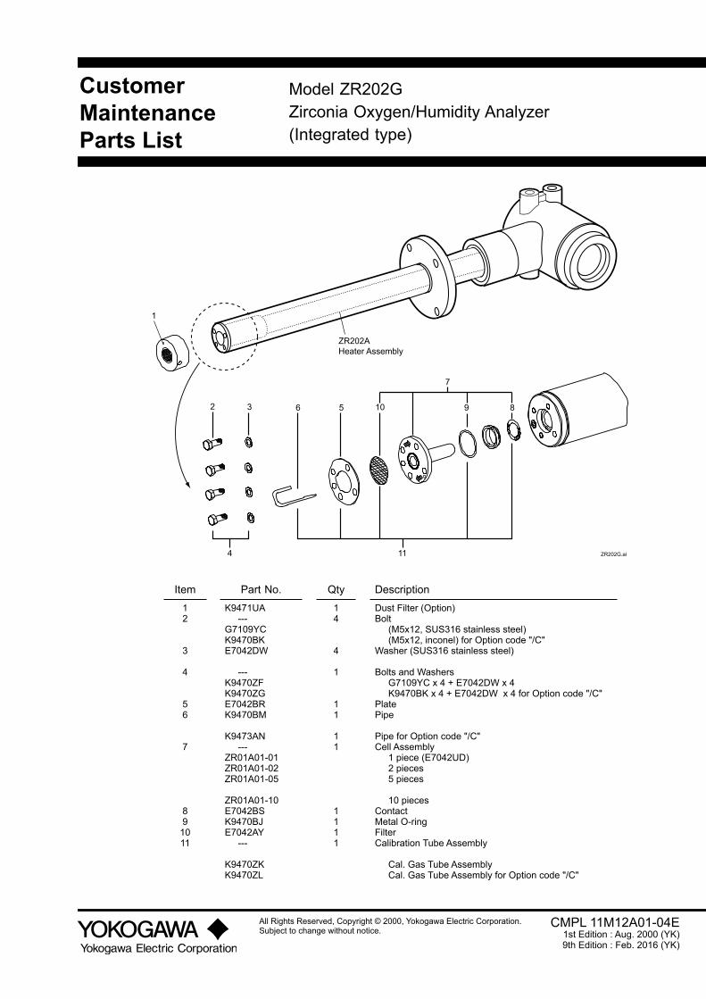
CustomerMaintenanceParts List
All Rights Reserved, Copyright © 2000, Yokogawa Electric Corporation.Subject to change without notice.
Model ZR202GZirconia Oxygen/Humidity Analyzer(Integrated type)
CMPL 11M12A01-04E1st Edition : Aug. 2000 (YK)9th Edition : Feb. 2016 (YK)
1
2 3 6 5 10 9 8
7
4 11 ZR202G.ai
ZR202AHeater Assembly
Item Part No. Qty Description12
3
4
56
7
891011
K9471UA ---G7109YCK9470BKE7042DW
---K9470ZFK9470ZGE7042BRK9470BM
K9473AN ---ZR01A01-01ZR01A01-02ZR01A01-05
ZR01A01-10E7042BSK9470BJE7042AY ---
K9470ZKK9470ZL
14
4
1
11
11
1111
Dust Filter (Option)Bolt (M5x12, SUS316 stainless steel) (M5x12, inconel) for Option code "/C"Washer (SUS316 stainless steel)
Bolts and Washers G7109YC x 4 + E7042DW x 4 K9470BK x 4 + E7042DW x 4 for Option code "/C"PlatePipe
Pipe for Option code "/C"Cell Assembly 1 piece (E7042UD) 2 pieces 5 pieces
10 piecesContactMetal O-ringFilterCalibration Tube Assembly
Cal. Gas Tube Assembly Cal. Gas Tube Assembly for Option code "/C"

CMPL 11M12A01-04E 9th Edition : Feb. 2016 (YK)
Hood for ZR202G
ZR202G_F.ai
1
Item Part No. Qty Description
1 K9472UF 1 Hood
CustomerMaintenanceParts List
All Rights Reserved, Copyright © 2001, Yokogawa Electric Corporation.Subject to change without notice.
Model ZR20HAutomatic Calibration Unit for Integrated type Zirconia Oxygen/Humidity Analyzer (ZR202G)
CMPL 11M12A01-12E1st Edition : Feb. 2001 (YK)4th Edition : Feb. 2016 (YK)
SPAN IN REF IN ZERO IN
10PS
IS
S-2C
2-10
NU
PR
O
1
Item Part No. Qty Description
1 K9473XC 1 Flowmeter

CustomerMaintenanceParts List
All Rights Reserved, Copyright © 2000, Yokogawa Electric Corporation.Subject to change without notice.
Model ZO21SZirconia Oxygen Analyzer/ High TemperatureHumidity Analyzer, Standard Gas Unit
CMPL 11M3D1-01E1st Edition : Jan. 2000 (YK)4th Edition : Mar. 2011 (YK)
1 2
3
Item Part No. Qty Description
1 ——— 1 Pump (see Table 1)
2 E7050BA 1 Zero Gas Cylinder (x6 pcs)
3 E7050BJ 1 Needle Valve
Table 1
Power PumpAC 100 V 110 115
E7050AU
AC 200 V 220 240
E7050AV


i
IM 11M12A01-04E 11th Edition : Jul. 19, 2017-00
Revision Informationl Manual Title : Model ZR202G Integrated type Oxygen/Humidity Analyzerl Manual No. : IM 11M12A01-04E
Jul. 2017/11th Edition Changed flange materials of ZR202G, ZO21R and ZH21B. (pages 2-3, 2-6 to 2-11)May 2017/10th Edition Addition RoHS etc. (pages i, v, vii, 2-2)Feb. 2016/9th Edition Bound up with IM 11M12A01-05E. IM 11M12A01-05E is obsoleted version. Whole review. CMPL 11M12A01-04E and CMPL 11M12A01-12E are updated.Aug.2015/8th.Edition Revised section 2.1.1 Some spell error corrections and addtion of specification description. 2.1.2 “ZR202G Integrated type Zirconia Oxygen Analyzer”: Deleted the C-tick, Safety and EMC
conforming standards. 2.4.3 “Stop Valve”: Changed of the weight and dimensions. 2.4.4 “Check Valve”: Changed of the weight. 5.1 “General” Table 5.1: Deleted cable type.
“General”: Added “WARNING”. CMPL. “Customer Maintenance Parts List”: CMPL 11M12A01-04E is updated to 8th edition.Jan. 2012/7th Edition Revised and Corrected over allSep. 2006/6th Edition Revised section 2.4.5 “Air Set,” Part No. K9473XH or K9473XJ, Standard Specification: Changed descriptions
partly; “Air Set,”Part No. G7004XF or K9473XG, Standard Specification: Changed descriptions partly;
2.4.7 “Cylinder Regulator Valve (Part No. G7013XF or G7014XF)”, Standard Specifications; Changed descriptions partly and drawing;
5.3 “Wiring Power and Ground Terminals”: Added description in Figure 5.5; 5.3.2 “Wiring for Ground Terminals”: Added item (4); 7.4.5 “Changing Set Values”: Changed description in table (1); 7.9.2 “Checking Calibration Contact Output”: Changed description in table 7.10; 8.3.2 “Preference Order of Output Hold Value”: Deleted “or blow-back”; 8.3.3 “Output Hold Setting”: Table 8.5, Parameter code C06, “maintenance” should read
“calibration”; 8.3.4 “Default Values”: Table 8.6, Deleted “or blow-back”; 8.5.1 “Output Contact”: Made some corrections; 8.5.2 “Setting Output Contact”:
Table 8.10, Changed descriptions; WARNING: Deleted second warning;
9.2.2.2 “Semi-automatic Calibration”: Table 9.3, Added note; 10.4 Table 10.6, Contact-related Items in Group E. Deleted some codes; 12.2.1 “What is an Alarm?”: Table 12.2, Added Alarms 11 and 13; 12.2.2.2 Alarm 6: Changed descriptions; 12.2.2.3 Alarm 7: Changed descriptions; • p. 12-7 and 12-8, Added Sections 12.2.2.6 and 12.2.2.7; • CMPL Changed part numbers of Items 4, 12 and 13; 2.1.2 “ZR202G Integrated type Oxygen Analyzer” Safety and EMC conforming standard: Added
Caution. 2.1.2 “ZR202G Integrated type Oxygen Analyzer” Model and Codes: Added Note. 8.3 “Output Hold Setting,” “Table 8.4 Analog Output Hold Setting”: Added Note. 8.3.3 “Output Hold Setting,” “Table 8.5 Parameter Codes for Output Holding”: Added Note. 10.4 “Reset,” “Table Output-related Items in Group C”: Added Note.

ii
IM 11M12A01-04E 11th Edition : Jul. 19, 2017-00
Apr. 2005/5th Edition Revised section Introduction Added description regarding modification 1.2.1 “ System Components” Changed part numbers of air set in table 2.1.2 Changed safety and EMC conforming standards and paint colors 2.2.2 Changed Finish color 2.3 Added description “ Non CE Mark” 2.4.5 “ Air Set” Changed part numbers and drawing of air set 4.2.1 “ Piping Parts for System 2” Change part numbers of air set in Table 4.2 4.4.1 “ Piping Parts for a System using Detector with Pressure Compensation” Changed part
numbers of air set in Table 4.3July 2003/4th Edition Revised section Notation of flange specification unified Dust guard protector, G7004XF/K9473XG Air set added CMPL 11M12A01-04E Cell assembly parts no. changed, revised to 5th edition.Sep. 2001/3rd Edition Revised section 1.2 Model ZR202A Heater Assembly added 2.2.1 ZA8F Flow Setting Unit error corrected 2.7.8 Model ZR202A Heater Assembly added 8.6 Table 8.12 Input Contact Functions changed 11.1.3 Reference document added to Replacement of the Heater Assembly Heater Assembly added to CMPL 11M12A01-04E CMPL 11M12A01-04E Model ZR20H changedMar. 2001/2nd Edition Revised section 1.1.3 Explanation changed in “System 3” example 1.2.1 ZR20H added to list of Equipment Models 2.1.2 Some changes to ZR202G Integrated type in MS code table, and notes added 2.2 Reference gas pressure of ZA8F with check valve changed, detailed explanation added to
ZR20H Automatic Calibration Unit 3.3 Added detail to 3.3 Installation of ZR20H Automatic Calibration Unit 3.5 Corrected errors in Insulation Resistance Test Wiring Diagram 4.3 Added explanation for piping to System 3 example 6.1 Added Filter to 6.1 ZR202G Detector 6.2 Added Names and Functions to 6.2 ZR20H Automatic Calibration Unit 7.1 Air-set secondary pressure with check valve changed 7.10.2 Reference gas pressure of ZA8F with check valve changed 10.6.1 Reference gas pressure of ZA8F with check valve changed 11.1 Added Filter to 11.1 Inspection and Maintenance of the ZR202G Detector 12.2.1 Corrected explanation of Alarm 10 Added Filter to CMPL 11M12A01-04E, and added ZR20H Automatic Calibration Unit to CMPL
11M12A01-12EOct. 2000/1st Edition Newly published
Yokogawa Electric Corporation 2-9-32 Nakacho, Musashino-shi, Tokyo 180-8750, JAPAN Homepage: http://www.yokogawa.com/