Embed Size (px)
Citation preview

FORM 160.67-EG1 (107)
700 Through 2165 TR(2500 Through 7400 kW)
Utilizing HFC-134a
Model YST Steam-Turbine Drive Centrifugal
Liquid ChillersDesign Level F
mMetric Conversions

2 JOHNSONCONTROLS
TABLE OF CONTENTS
Introduction......................................................................................................................... 3Ratings............................................................................................................................... 5OptiView Control Center..................................................................................................... 6Equipment Specifications....................................................................................................7Accessories and Modifications..........................................................................................12Application Data................................................................................................................14Dimensions (Ft. - In.) – H Compressor Units....................................................................19Dimensions(Ft.-In.)–NozzleArrangements:. Evaporators – Compact Water Boxes – H Compressor Units..............................20 Evaporators – Marine Water Boxes – H Compressor Units..................................21 Refrigerant condensers – Marine Water Boxes – H Compressor Units................22Dimensions (Ft. - In.) – J Compressor Units......................................................................24Dimensions(Ft.-In.)–NozzleArrangements:. Evaporators – Compact Water Boxes – J Compressor Units...............................26 Evaporators – Marine Water Boxes – J Compressor Units...................................27 Refrigerant condensers – Marine Water Boxes – J Compressor Units.................28Steam Condenser..............................................................................................................30Approximate Unit Weights (Lbs.) ..................................................................................31Marine Water Box Weight Additions (Lbs.)..............................................................................32Dimensions (mm) H Compressor Units...............................................................................33Dimensions(mm)NozzleArrangements: Evaporators – Compact Water Boxes – H Compressor Units.........................................34 Evaporators–MarineWaterBoxes–HCompressorUnits.........................................35 Refrigerantcondensers–MarineWaterBoxes–HCompressorUnits.................................36Dimensions (mm) J Compressor Units................................................................38Dimensions(mm)NozzleArrangements: Evaporators – Compact Water Boxes – J Compressor Units................................40 Evaporators – Marine Water Boxes – J Compressor Units..............................41 Refrigerant condensers – Marine Water Boxes – J Compressor Units...........................42Approx imate Un i t We igh ts (Kg) . . . . . . . . . . . . . . . . . . . . . . . . . . . . . . . . . . . . . . . . . . . . . . . . . . . . . . . . 45Marine Water Box Weight Additions (Kg)...............................................................................46Guide Specifications....................................................................................................47SIMetricConversions..................................................................................................................56
NOMENCLATUREThemodelnumberdenotesthefollowingcharacteristicsoftheunit:
YSTVFVDJ4-KD71750090-14-0.6-33192C-FS
ChillerModel
EvaporatorCode
CondenserCode
CompressorCode
SteamTurbineBaseModel
SteamCondenserModel
DesignLevel
Special(Mandatory)
No.ofTurbineNozzles
TurbineExpansionRatio

FORM 160.67-EG1 (206)
JOHNSONCONTROLS 3
IntroductionTheYORKYST MaxE™Chillersofferacompletecombi-nationoffeaturesfortotalownersatisfaction.
MATCHED COMPONENTS MAXIMIZE EFFICIENCY
Overall chiller efficiency cannot be determined by analyz-ing the theoretical efficiency of any one chiller component. It requires a specific combination of heat exchanger, com-pressor, steam turbine and steam condenser performance toachievethelowestsystemsteamrate.YORKYSTMaxEchillertechnologymatcheschillersystemcomponentstoprovide maximum chiller efficiency under actual - not just theoretical-operatingconditions.
REAL-WORLD ENERGY PERFORMANCE
YORKpioneeredtheterm“Real-WorldEnergy”toillus-trate the energy-saving potential of focusing on chillerperformanceduringoff-designconditions.Off-design isnot only part load, but full load operation as well, with re-ducedenteringrefrigerantcondenserwatertemperatures(ECWTs). This is where chillers operate 99% of the time, andwhereoperatingcostsaddup.
TheYSTMaxEchillersaretheonlychillersdesignedtooperateonacontinuousbasiswithcoldECWTandfullrefrigerant condenser flow at all load points, taking full advantageofReal-Worldconditions.Thistypeofoperationbenefits the cooling tower as well; reducing cycling of the fan motor and ensuring good coverage of the cooling fill.
YORKYSTMaxE chillers offer the most efficient Real-World operation of any chiller, meaning lower operating costs and an excellent return on your chiller investea-ment.
OPEN DRIVE DESIGN
YORK YST MaxE centrifugal chillers utilize an opendrivecompressorthatenablestheuseofvariousdrives.Specifically, the YST uses a Steam Turbine to provide therotationalpowertodrivethechiller.Theuseofsteamas the motive energy provides owners the ability to take advantageofthemosteffectiveenergysourceavailableeitherbyusingsteamonlyorbycomplementingthiswithother“hybrid”energysourcessuchaselectricorgas.
HIGH-EFFICIENCY HEAT EXCHANGERS
YSTMaxEchillerheatexchangersofferthelatesttech-nologyinheattransfersurfacedesigntogivemaximumefficiency and compact design. Water, refrigerant and steamsidedesignenhancementsminimizebothenergyconsumptionandtubefouling.
SINGLE-STAGE COMPRESSOR DESIGN AND EF-FICIENCY PROVEN IN THE MOST DEMANDING APPLICATIONS
Designed to be the most reliable chillers we’ve ever made, YORKYSTMaxEcentrifugalchillersincorporatesingle-stagecompressordesign.Withfewermovingpartsandstraightforward, efficient engineering, YORK single-stage compressors have proven durability records in hospitals, chemical plants, gas processing plants, the U.S. Navy, and inotherapplicationswhereminimaldowntime isacrucialconcern.
In thousands of installations worldwide, YORK single-stage compressors are working to reduce energy costs. High strength aluminum-alloy compressor impellersfeature backward-curved vanes for high efficiency. Airfoil shaped pre-rotation vanes minimize flow disruption for the most efficient part load performance. Precisely positioned and tightly fitted, they allow the compressor to unload smoothly from 100% to minimum load for excellent opera-tioninairconditioningapplications.
MURRAY STEAM TURBINES - PROVEN EXPERI-ENCE AND HIGH EFFICIENCY
The YORK compressor, driven by a Murray Turbo-machinery multistage steam turbine provides the bestcombination of optimized efficiency and proven track record.Murraymultistageturbinesareusedtogetherwithinnovative, automated controls to integrate the turbine and compressorseamlessly.Theabilityofthesteamturbinetovaryrotationalspeedprovidesoptimalcompressoref-ficiency at all operating conditions and builds on YORK’s reputationforthebestin“Real-WorldEnergy”.Optionalautomated start and shutdown controls eliminate thetraditional manual intervention associated with steamturbinesystems.
FLEXIBILITY OF AN ITT STEAM CONDENSER PACKAGE
Unique to the YST chiller is the packaging of a steam condensersuitableformountingonthechilleroralongsidedependingonsiterequirements.BydesigningthesteamcondenserformountingonthechillertheYSTfootprintisnolargerthanthatoftraditionalchillerssavingspaceandsimplifyingplantlayoutwhentheYSTchillerisusedincombinationwithotherYORKchillers.Thesamesteamcondenser package may be installed off the chiller, if re-quired, without modification or eliminated altogether where asteamcondensationsystemalreadyexistsonsite.

4 JOHNSONCONTROLS
Introduction (continued)
PRECISION CONTROL OF COMPRESSOR OIL PRESSURE
Utilizingourexpertiseinvariablespeeddrivetechnologyand applications, YORK has moved beyond the fixed headandbypassapproachofoilpressurecontrol.Theoldapproachonlyassuresoilpressureattheoutletofthepump rather than at the compressor, and allows no adjust-eamentduringchilleroperation.TheYSTMaxEchillersfeature a variable speed drive oil pump, monitoring and providing the right amount of oil flow to the compressor onacontinuousbasis.Thisdesignalsoprovidessophisti-catedelectronicmonitoringandprotectionoftheoilpumpelectrical supply, ensuring long life and reliable operation oftheoilpumpmotor.Variablespeeddrivetechnologyreduces oil pump power consumption, running only at the speed required, rather than at full head with a pressure regulatingbypassvalve.
FACTORY PACKAGING REDUCES FIELD LABOR COSTS
YORKYSTMaxE centrifugal chillers are designed to keep installationcostslow.Whereinstallationaccessisnota
problem, the chiller can be shipped completely packaged withsteamturbinedrivelinefactoryinstalled.Thesteamcondenser is a modular design, packaged to facilitate site installation on top of the refrigerant condenser orfloor mounted adjacent to the chiller, either arrangement requiringminimalpipingtocompletetheinstallation.Theentiresystemrequiresasinglepointpowerconnectiontominimizeonsitewiring.
TAKE ADVANTAGE OF COLDER COOLING TOWEr-WATER TEMPERATURES
YORKYSTMaxEcentrifugalchillershavebeendesignedto take full advantage of colder cooling tower water temperatures, which are naturally available during most operatinghours.Considerableenergysavingsareavail-able by letting tower water temperature drop, rather than artificially holding it above 75°F (24°C), especially at low load, as some chillers require.

FORM 160.67-EG1 (206)
JOHNSONCONTROLS 5
RatingsCOMPUTERIZED PERFORMANCE RATINGS
Each chiller is custom-matched to meet the individualbuildingloadandenergyrequirements.Alargenumberofstandardheatexchangersandpassarrangementsareavailabletoprovidethebestpossiblematch.
Itisnotpracticaltoprovidetabulatedperformanceforeachcombination, as the energy requirements at both full and part load vary significantly with each heat exchanger and passarrangement.Computerized ratingsareavailablethrough each YORK sales office. These ratings can be tailored to specific job requirements.
OFF-DESIGN PERFORMANCE
Since the vast majority of its operating hours are spent at off-design conditions, a chiller should be chosen not only to meet the full load design, but also for its ability to perform efficiently at lower loads and lower tower water
temperatures. It is not uncommon for chillers with thesamefullloadtohaveanoperatingcostdifferenceofover10% due to part-load operation.
Part load information can be easily and accurately gener-atedbyuseofthecomputer.Andbecauseitissoimportantto an owner’s operating budget, this information has now been standardized in the form of an Integrated Part Load Value (IPLV), and Non-Standard Part Load Value (NPLV). The IPLV / NPLV formulas, in accordance with ARI Stan-dard 550/590 guidelines, much more closely track actual chiller operations. A more detailed analysis must take into account actual building load profiles, and local weather data. Part load performance data should be obtained for each job using its own design criteria.

6 JOHNSONCONTROLS
Optiview Control CenterYST OPTIVIEW CONTROL CENTER
The YORK OptiView Control Center, furnished as standard on each chiller, provides the ultimate in efficiency, auto-mation, monitoring, data recording, chiller protection and operating ease. The Control Center is a factory-mounted, wiredandtestedstate-of-the-artmicroprocessorbasedcontrol system for R134a centrifugal chillers. The panel is configured with a 10.4" diagonal color Liquid Crystal Display (LCD) surrounded by “soft” keys, which are rede-fined with one keystroke based on the screen displayed at that time. This revolutionary development makes chiller operation quicker and easier than ever before. Instead of requiring keystroke after keystroke to hunt for information on a small monochrome LCD screen, a single button reveals a wide array of information on a large, full-color illustration of the appropriate component, which makes informationeasiertointerpret.
TheLCDdisplayallowsgraphicanimateddisplayofthechiller, chiller sub-systems and system parameters; this allowsthepresentationofseveraloperatingparametersatonce.Thenoveluseofonscreenanimationenablesoperatorstomorereadily identifycomponentstatus.Inaddition, the operator may view a graphical representation ofthehistoricaloperationofthechilleraswellasthepres-entoperation.AStatusBarisdisplayedatalltimesonallscreens.ItcontainstheSystem-StatusLineandDetailsLine, the Control Source, Access Level, Time and Date. During turbine slow roll, startup, operation and coast-down, the system status will indicate vital information availableatanytime.Thelocationsofvariouschillerpa-rameters are clearly marked and instructions for specific operationsareprovidedonmanyof thescreens.DatacanbedisplayedineitherEnglishorSIunits.
Security access is provided to prevent unauthorizedchanges of setpoints.This is accomplished with threedifferentlevelsofaccessandpasswordsforeachlevel.There are certain screens, displayed values, program-mablesetpointsandmanualcontrolsnotshownthatarefor servicing the chiller.Theyareonlydisplayedwhenloggedinatserviceaccesslevel.IncludedinthisistheAdvanced Diagnostics and troubleshooting informationforthechillerandthepanel.
Thecontrolcenterpowersupplyisprovidedfromafused2 KVA transformer located in the power panel.
Thecontrolcenterisalsofusedtoprovideindividualover-currentprotectedpower for the remotemountedwaterpumpmotorstarters(suppliedbyothers)andthecontrolsinstalledonthechiller.Numberedterminalstripsforwir-ing such as Remote Start / Stop, Chilled Water Pump andLocalorRemoteCyclingdevicesareprovided.ThePanel also provides field interlocks that indicate the chiller
status.ThesecontactsincludeaRemoteModeReady-to-Start, a Controlled Shutdown, a Safety Shutdown and achillerRuncontact.Systempressuresaremonitoredwith transmitters (4-20 mA) and transducers (0-5 VDC). System temperatures are monitored using thermistorsandRTD’s.
Setpoints can be changed from a remote location via 0-10VDC and 4-20mA, contact closures or through serial communications. The adjustable remote reset range [up to 20°F (11.1°C)] provides flexible, efficient use of remote sig-naldependingonresetneeds.SerialdatainterfacetotheYORKISNBuildingAutomationSystem(BAS)isthroughthe optional Microgateway Card, which can be mounted insidetheControlCenter.Interfacesusingotherindustrystandard protocols such as MODBUS RTU, Johnson NZ, BACnet MS/TP, LONMARK and ASCII are available.
The operating program is stored in non-volatile mem-ory to eliminate chiller failure due to AC power failure/battery discharge. Programmed setpoints are retained in lithium battery-backed RTC memory for 11 years minimum.
Smart Freeze Point Protection will run the chiller at 36°F (2.2°C) leaving chilled water temperature eliminating nuisancetripsonLowWaterTemperature.Thesophisti-catedprogramandsensorswillmonitorthechillerwaterandevaporatorrefrigerantliquidtemperaturestopreventfreezeup.Everyprogrammablepointhasapop-upscreenwith the allowable ranges, so that the chiller can not be programmedtooperateoutsideofitsdesignlimits.
Thecapacity control logicprovidesstableoperationatmaximum efficiency at off design conditions by modulating the turbine speed, compressor pre-rotation vanes and hot gasby-passvalve.
When the power is applied to the chiller, the HOME screen isdisplayed.Thisscreendisplaysavisualrepresentationofthechillerandacollectionofdatadetailingimportantoperations and parameters. The primary values thatneedtobemonitoredandcontrolledareshownonthisscreen. The owner can be confident that YORK’s OptiView control system for the YST is unequalled in its design, controlfeaturesandprotectionsystems.See“EquipmentSpecifications” for a more detailed description of OptiView features.

FORM 160.67-EG1 (206)
JOHNSONCONTROLS 7
Equipment SpecificationsGENERAL
TheYORKYST MaxE Centrifugal Liquid Chillers arecompletely factory-packaged including the evaporator, refrigerant condenser, compressor, steam turbine, lubrica-tion systems, power panel, control center, and all inter-connectingunitpipingandwiring.Thesteamcondenserpackage is shipped separately suitable for direct mounting ontothechillerormountingalong-side.
Theinitialchargeofrefrigerantandoilissuppliedforeachchiller.Whentheoptionalrefrigerantcondenserisolationvalves are ordered, the unit may ship fully charged with refrigerantandoil.Actualshippingprocedureswilldependon a number of project-specific details.
The services of a YORK factory-trained, field service rep-resentative are incurred to supervise or perform the final leak testing, charging, the initial start-up, and concurrent operatorinstructions.
COMPRESSOR
Thecompressorisasingle-stagecentrifugaltypepoweredbyasteam turbine.Thecasing is fullyaccessiblewithvertical circular joints and fabricated of close-grain cast iron.Thecompleteoperatingassemblyisremovablefromthecompressorandscrollhousing.
Therotorassemblyconsistsofaheat-treatedalloysteeldrive shaft and impeller shaft with a high strength, cast aluminum alloy, fully shrouded impeller. The impeller isdesignedforbalancedthrustandisdynamicallybal-anced and overspeed tested for smooth, vibration free operation.
The insert-type journal and thrust bearings are fabricated of aluminum alloy and are precision bored and axiallygrooved. The specially engineered, single helical gears withcrownedteetharedesignedsothatmorethanonetoothisincontactatalltimestoprovideevendistributionofcompressorloadandquietoperation.Gearsareintegrallyassembled in the compressor rotor support and are film lubricated.Eachgearisindividuallymountedinitsownjournal and thrust bearings to isolate it from impeller and turbineforces.
CAPACITY CONTROL
During part load operation at off design conditions, the chillercapacityisreducedtomaintainaconstantleavingchilled liquid temperature by first decreasing the speed, then closing the compressor pre-rotation vanes (PRV). This provides capacity reduction from 100% to 15% of design for normal air conditioning applications.Thespeediscontrolledbyapneumaticallyactuatedgovernorvalve which throttles the inlet steam flow to the turbine to
maintainthespeeddictatedbythecapacitycontrollogic.If the tower water temperatures must be held above 75°F for other chillers, the capacity control logic automatically limits the amount of speed reduction and PRV closure tomaintainstableoperation.Thehotgasby-passvalveisthenmodulatedtomaintainaconstantleavingchilledliquid temperature with loads down to 10% of design.
The vanes are actuated by an external, electric PRV ac-tuator. Rugged, airfoil shaped, cast manganese bronze vanes are precisely positioned by solid vane linkages connectedtotheelectricactuator.
COMPRESSOR LUBRICATION SYSTEM
Lubrication oil is force-fed to all bearings, gears and rotatingsurfacesbyavariablespeeddrivepumpwhichoperates prior to startup, continuously during operation andduringcoastdown.Agravity-fedoilreservoirisbuiltintothetopofthecompressortoprovidelubricationduringcoastdownintheeventofapowerfailure.
An oil reservoir, separate from the compressor, contains the submersible oil pump, 2 HP pump motor and 3000 watt immersion-typeoilheater.Theoilheateristhermostati-callycontrolledtoremoverefrigerantfromtheoil.
Oil is filtered by an externally mounted 1/2 micron replace-able cartridge oil filter equipped with service valves. Oil is cooled via a shell and tube, water cooled oil cooler sized touserefrigerantcondenserwaterasthecoolingmedium.Theoilsideoftheoilcoolerisprovidedwithservicevalves.Oilpipingiscompletelyfactory-installed.Thewatersideofthe oil cooler is provided with service valves, inlet strainer and solenoid valve for automatic start/stop of cooling water flow. Water piping is factory installed with customer con-nectionsconvenientlybroughttotheedgeofthechillerpackage and clearly tagged for installation. An automatic oilreturnsystemrecoversanyoilthatmayhavemigratedto the evaporator. Oil temperature control is by an Amot, threewaytemperaturecontrolvalve.
STEAM TURBINE
The steam turbine is a high efficiency multistage de-sign operating at a nominal 4500 rpm design maximum speed.
The turbine is packaged on a driveline base, completely factory piped. The driveline base has a mating flange on shaft end of the package that will bolt directly to the compressor D-flange face providing a rigid interface between turbine package and compressor. Complete turbine/compressor driveline is factory aligned prior to shipment.Turbinedriveshaftisdirectlyconnectedtothecompressor shaft with a flexible disc coupling. Coupling isofanallmetalconstructionwithnowearingpartsas-

� JOHNSONCONTROLS
Equipment Specifications (continued)
suringlonglifeandnolubricationrequirementsprovidinglowmaintenance.
Theturbinecasingishorizontallysplitdesignedtoallowlongitudinal thermal expansion without the affectingalignment or efficiency of the turbine. The shaft and wheels are alloy steel with the wheels shrunk and keyed to the shaft. The turbine blades are 403 grade stainless steelandtheshaftisgroundthroughoutwithstainlesssteelsprayedinthecarbonringendglandcontactarea.Stainless steel nozzles are furnished throughout theturbine.Carbonringendglandanddiaphragmsealsarefurnished.Turbineendglandcarbonringseals(minimumfive seals per end gland) are separated by partitions of stainlesssteel.
A stainless steel, inlet steam strainer with adequate size and mesh to minimize the pressure drop is supplied.Strainer is removable without breaking the steam piping connections.
Blanket insulation is furnished on the steam chest and barreloftheturbineforoperatorprotection.
The turbine speed is controlled by a governor valvewhichisintegratedwiththechillercontrols.Thevalveisofstainlesssteelwithstainlesssteelseatsanddesignedto control flow throughout the entire operating range of theturbine.Thesystememploysanoverspeedgovernordesigned to close an independent high performancebutterfly trip valve with a pneumatic actuator when the turbine speed exceeds 110 percent of the maximum continuousoperatingspeedoftheturbine.Activationoftheindependenttripvalvecausesthegovernorvalvetoalso close. A micro switch is furnished on the trip linkage forthecustomer’suse.
TURBINE LUBRICATION SYSTEMS
RingOilLubricatedTurbines-Drivepowerslessthan1700Hp (1268 kW) only:
The bearings are steel backed, babbitt lined, split
sleevetype.Thedesignissuchthatthebottomhalfisremovablewiththeshaftinplace.Thebearinghousinghasprovisionsforairpurgingofthehous-ingshaftseals.Thethrustbearingisanantifrictionball bearing, accessible and removable without liftingthetophalfoftheturbinecasing.Oilcoolingisbywatercooledbearinghousings.
External, Pressurized Lube System Turbines:
The bearings are steel backed, babbitt lined, split sleeve type.Thedesign is such that thebottomhalfisremovablewiththeshaftinplace.Thebear-
inghousinghasprovisions forairpurgingof thehousingshaftseals.Thethrustbearingisadoubleacting, Kingsbury type. The lubrication system is integraltotheturbinedrivelinebaseandcompletelyfactorypiped.Thelubricationsystemconsistsofashaft driven main oil pump, motor driven auxiliary oil pump, water cooled shell and tube oil cooler, 25 micron full flow oil filter and separate oil reservoir withlevelgauge.OiltemperaturecontrolisbyanAmot, three way temperature control valve.
STEAM CONDENSER PACKAGE
A steam condenser is provided to condense exhauststeam at vacuum pressures to maintain efficient turbine operation.Thesteamcondenserwatercircuitispipedin series with the refrigerant condenser, eliminating a separatecoolingwatercircuitandisdesignedtomini-mizepressuredropforenergysavings.
The steam condenser is furnished fully packaged. The package includes a single hotwell pump, a single liquid ring vacuum pump for air removal, atmospheric relief valve and level control system. The package is factory piped, wired and mounted on a common structural steel framesuitableforinstallationontherefrigerantcondens-er or floor mounting adjacent to the chiller system.
Condensateleveliscontrolledbyalevelcontrolsystemwith two (2) pneumatic control valves - one for re-circula-tionandtheotherforremovalofcondensate.Theliquidringvacuumpumpiscapableofdrawingthecondenserdown to operating pressure in approximately 10 minutes. Hotwell pump is single-stage, end suction suitable for hotwell service. Steam side is designed for 15 psig (100 kPa) and 30" Hg Vac (760 mmHg).
Atmosphericreliefvalveisawatersealtypewithexternalhandwheel, sized in accordance with the Heat Exchange InstituteStandards(HEI)forprotectionofthesteamtur-bine exhaust, steam trunk and steam condenser.
All key control and monitoring parameters are integrated with the chiller control panel. In addition, auxiliary pres-suregaugesarelocatedatthecondensersteaminletand condensate pump discharge piping, and temperature gauges are located at the steam inlet, cooling water inlet and outlet, and the hotwell.
To facilitate rigging, condenser is separable from the skid by unbolting. Piping is outfitted with unions at suitable break-points. Both condenser and skid are outfittedwithliftinglugsforbothverticalandhorizon-tallifting.

FORM 160.67-EG1 (206)
JOHNSONCONTROLS �
HEAT EXCHANGERS
Shells
Evaporator, refrigerant condenser and steam condenser shellsarefabricatedfromrolledcarbonsteelplateswithfusion welded seams. Carbon steel tube sheets, drilled and reamed to accommodate the tubes, are welded to the end of each shell. Intermediate tube supports arefabricated from carbon steel plates, drilled and reamed to eliminatesharpedges.Therefrigerantsideofeachshellisdesigned, tested, and stamped in accordance with ASME Boiler and Pressure Vessel Code, Section VIII - Division I, orotherpressurevesselcodeasappropriate.Thesteamsideofthesteamcondenserisdesignedinaccordancewith the Heat Exchange Institute (HEI), an industry stan-dardforsteamcondensertechnology.
Tubes
Refrigerant heat exchanger tubes are state-of-the-art, high-efficiency, externally and internally enhanced type to provideoptimumperformance.Tubesinboththeevapo-rator and refrigerant condenser are 3/4" O.D. (19 mm) copper alloy and utilize the “skip-fin” design, providing a smoothinternalandexternalsurfaceateachintermedi-ate tube support. This provides extra wall thickness (up to twice as thick) and non-work hardened copper at the support location, extending the life of the heat exchangers. Eachtubeisrollerexpandedintothetubesheetsprovidinga leak-proof seal, and is individually replaceable. Steam condenser tubes are copper, providing economical and efficient heat transfer.
Evaporator
The evaporator is a shell and tube, flooded type heat ex-changer.Adistributortroughprovidesuniformdistributionofrefrigerantovertheentireshelllengthtoyieldoptimumheat transfer. A suction baffle or aluminum mesh elimina-torsarelocatedabovethetubebundletopreventliquidrefrigerant carryover into the compressor. A 1-1/2" (38 mm)liquidlevelsightglassisconvenientlylocatedonthesideoftheshelltoaidindeterminingproperrefrigerantcharge.Theevaporatorshellcontainsadualrefrigerantrelief valve arrangement set at 180 psig (1241 kPa); or single-relief valve arrangement, if the chiller is supplied with the optional refrigerant isolation valves. A 3/4" (19 mm) flare male charging connection is provided.
Refrigerant Condenser
The refrigerant condenser is a shell and tube type, with a discharge gas baffle to prevent direct high velocity im-pingement on the tubes. The baffle is also used to distrib-ute the refrigerant gas flow properly for most efficient heat transfer.Anintegralsub-coolerislocatedatthebottomoftherefrigerantcondensershellprovidinghighlyeffectiveliquidrefrigerantsubcoolingtoprovidethehighestcycle
efficiency. The refrigerant condenser contains dual refrig-erant relief valves set at 235 psig (1620 kPa).
Steam Condenser
Steamcondenserconstructionisoftheshellandtubetypeof welded steel construction with 3/4" OD (19 mm) prime surface copper tubes, roller-expanded into tube sheets. Animpingementplatelocatedbelowthecentrallylocatedsteam inlet redirects steam flow to protect the tubes from highvelocitysteam.Subcoolingsectionsinthecondensercool non-condensibles sufficiently below the condensing temperaturetherebyreducingthevacuumpumpcapacityrequired. Water side is suitable for a maximum working pressure of 150 psig (1030 kPa). An atmospheric relief valve, sized per HEI to protect the condenser, is included. This relief valve is set to open at 1-2 psig (7-14 kPa) and willpreventpressureinthecondensershellfromexceed-ing 10 psig (69 kPa). Seal water is required to maintain a liquid seal in the valve. An inlet and overflow connection isprovidedonthevalveforthispurpose.
Water Boxes
Thewaterboxesarefabricatedfromsteelandaremarinestyle(compactormarineavailableonevaporator).Thestandard design working pressure is 150 psig (1030 kPa) and the chiller boxes are tested at 225 psig (1550 kPa). Steam condenser boxes are tested at 215 psig (1480kPa). Integral steel water baffles are located and welded within thewaterboxtoprovidetherequiredpassarrangements.Stub-outwaternozzleconnectionswithVictaulicgroovesareweldedtothewaterboxes.Thesenozzleconnectionsare suitable for Victaulic couplings, welding or flanges, and are capped for shipment. Plugged 3/4" NPTI (19 mm) drain andventconnectionsareprovidedineachwaterbox.
REFRIGERANT FLOW CONTROL
Refrigerant flow to the evaporator is controlled by the YORK variable orifice control system. Liquid refriger-ant level iscontinuouslymonitoredtoprovideoptimumsubcooler, refrigerant condenser and evaporator perfor-mance. The variable orifice electronically adjusts to all Real-World operating conditions, providing the most ef-ficient and reliable operation of refrigerant flow control.
POWER PANEL
All motor contactors and circuit protectors, the compressor oilpumpvariablespeeddriveandthecontrolpowertrans-former are contained in an enclosure installed adjacent to the OptiViewcontrolcenter.Amainpowerdisconnectswitchissuppliedwhichprovidestheterminationpointsforcustomer’ssinglepointpowersupplywiring.

10 JOHNSONCONTROLS
Equipment Specifications (continued)
OPTIVIEW CONTROL CENTER
General
Thechilleriscontrolledbyastand-alonemicroprocessorbasedcontrolcenter.Thechillercontrolpanelprovidescontrol of entire system, including turbine and steam condenseroperationandmonitoring.
The control panel includes a 10.4". diagonal color liquid crystal display (LCD) surrounded by “soft” keys which are redefined based on the screen displayed at that time, mounted in the middle of a keypad interface and installed in a locked enclosure. The screen details all operations and parameters, using a graphical representation of the chiller and its major components. Panel text is in English only.Datacanbedisplayed ineitherEnglishorMetricunits.Additionalfeaturesare:• Smart Freeze Point Protection capable of running
the chiller at 36°F (2.2°C) leaving chilled water temperatureeliminatingnuisancetripsonlowwatertemperature.Thesophisticatedprogramandsensorsmonitorthechillerwaterandevaporatorrefrigerantliquidtemperaturestopreventfreeze-up.
• Thepaneldisplayscountdowntimermessagessotheoperator knows when functions are starting and stop-ping.Everyprogrammablepointhasapop-upscreenwith the allowable ranges, so that the chiller can not be programmedtooperateoutsideofitsdesignlimits.
• Security access is built in to prevent unauthorizedchange of setpoints, to allow local or remote control of the chiller, and to allow manual operation of the pre-rotationvanesandoilpump.AccessisthroughIDand password recognition, which is defined by three different levels of user competence: view, operator, andservice.
• Trendingdataisavailablewiththeabilitytocustomizepointsfromonceeverysecondtoonceeveryhour.Thepanelwilltrendupto6differentparametersfroma list of over 140, without the need of an external monitoringsystem.
• The operating program is stored in non-volatilememorytoeliminatereprogrammingthechillerduetoAC power failure or battery discharge. Programmed setpoints are retained in lithium battery-backed RTC memory for a minimum of 11 years with power re-movedfromthesystem.
• Includes an RS-232 port to output all system operating data, shutdown/cycling message, and a record of the last 10 cycling or safety shutdowns to a field-supplied printer.Datalogstoaprinteratasetprogrammableinterval.Thisdatacanbeprepro-grammedtoprintfrom 1 minute to 1 day.
• Thetextdisplayedwithinthesystemstatusandsys-tem details field is displayed as a color-coded mes-
sage to indicate severity: red for safety fault, orange for cycling faults, yellow for warnings, and green for normalmessages.
Thechillercontrolpanelprovidesamultitudeofdiagnosticandoperatingdatatoonumeroustocovercompletelyinthis guide. However, a general description of some of thedataavailableandexamplesofthevariousscreensprovidedfollows:
Somehighlights(notall inclusive)ofthedataavailableonthepanelareasfollows:
System Operating Information
Evaporator
• Leavingandreturnchilledwatertemperature• Refrigerantliquidtemperature-evaporator• Evaporatorpressure• Hotgascontrolstatus• Chilled water flow
Refrigerant Condenser
• Entering and leaving refrigerant condenser watertemperature
• Refrigerantliquidtemperature-refrigerantcondens-er
• Refrigerantcondenserpressure• Subcoolerrefrigerantliquidlevel• Subcoolerrefrigerantliquidlevelcontrolstatus• Refrigerant condenser water flow
Compressor
• Compressordischargetemperature• Compressoroiltemperature• Compressorsupplyoilpressure• Compressor thrust bearing proximity probe gap (J
compressorsonly)• Pre-rotation vanes (PRV) position
Steam Turbine
• Turbineshaftendbearingtemperature• Turbinegovernorendbearingtemperature• Turbineinletsteamtemperature• Turbineinletsteampressure• Turbine first stage steam pressure• Turbineexhaustpressure• Turbinespeed• Turbinegovernorcontrolstatus
Steam Condenser
• Hotwellcondensatelevel• Hotwelllevelcontrolstatus

FORM 160.67-EG1 (206)
JOHNSONCONTROLS 11
Safety shutdowns (will prevent unit from starting or operating)
• Evaporator-lowpressure• Evaporator - low temperature (Smart Freeze Point
Protection)• Evaporator-transducerorleavingliquidprobefail-
ure• Evaporator-transducerortemperaturesensorfail-
ure• Refrigerant condenser - high pressure contacts
open• Refrigerantcondenser-highpressure• Refrigerantcondenser-pressuretransducerout-of-
range• Compressordischarge-hightemperature• Compressordischarge-lowtemperature• Compressoroil-hightemperature• Compressoroil-lowdifferentialtemperature• Compressoroil-highdifferentialpressure• Compressoroil -sumppressuretransducerout-of-
range• Compressoroil-differentialpressurecalibration• Compressor oil - variable speed pump - pressure
setpointnotachieved• Compressorthrustbearing-proximityprobeuncali-
brated(Jcompressorsonly)• Compressor thrustbearing-proximityprobeclear-
ance(Jcompressorsonly)• Compressorthrustbearing-proximityprobeout-of-
range(Jcompressorsonly)• Controlpanel-powerfailure• Turbinegovernorendbearinghightemperature• Turbineshaftendbearinghightemperature• Turbineoil-lowpressure• Turbineoil-hightemperature• Turbineunderspeed• Turbineexhausthighpressure• Standby hotwell pump fault (warning on failure of
primarypump)• Standby vacuum pump - no sealing water flow (warn-
ingonfailureofprimarysystem)• Standbyvacuumpump fault (warningon failureof
primarypump)• Hotwellcondensatehighlevel• Hotwellcondensatelowlevel
CODES AND STANDARDS
• ASME Boiler and Pressure Vessel Code - Section Vlll Division 1.
• Heat Exchange Institute (HEI), Industry Standard for SteamCondensers
• NEMA (SM23) Steam Turbines for Mechanical Drive Services
• Expansion Joint Manufacturers Assoc., Inc. (EJMA)• ARI Standard 550/590• ASHRAE 15 - Safety Code for Mechanical Refrigera-
tion• ASHRAEGuideline3-ReducingEmissionofHaloge-
natedRefrigerantsinRefrigerationandAir-Condition-ingEquipmentandSystems
• N.E.C.-NationalElectricalCode• OSHA-OccupationalSafetyandHealthAct
ISOLATION MOUNTING
Theunitisprovidedwithfourvibrationisolationmountsconsisting of 1" (25.4 mm) thick neoprene isolation pads for field mounting under the steel mounting plates located onthetubesheets.
REFRIGERANT CONTAINMENT
Therefrigerantcircuithasbeendesignedasa factory-packaged system. As such, it has minimum joints from which refrigerant can leak. The entire assembly has been thoroughly leak tested at the factory prior to shipment. TheYORKchiller includesservicevalvesconvenientlylocated to facilitate transfer of refrigerant to a remoterefrigerant storage/recycling system. Optional refrigerant condenserisolationvalvesallowstorageofthechargeintherefrigerantcondenser.
PAINT
ExteriorsurfacesareprotectedwithonecoatofCaribbeanblue, durable alkyd-modified, vinyl enamel, machinery paint.
SHIPMENT
Protective covering is furnished on the control center. Water nozzles are capped with fitted plastic enclosures. Entire unit is protected with industrial-grade, reinforced shrink-wrapped covering.

12 JOHNSONCONTROLS
Accessories and ModificationsFLOOR MOUNTED STEAM CONDENSER
As an alternative to the standard packaged location, the steam condenser package can be ordered for floor mount-ing adjacent to the chiller package. Prefabricated piping kits for the steam trunk, water piping and wiring between chiller package and steam condenser are not included with a floor mounted arrangement. These interconnect-ing components must be designed, supplied and installed bycustomer.
Note: Interconnecting components may be orderedthroughthefactoryviaaspecialquoteuponrequest(sitearrangementdetailswillbe requiredat timeof requestforquote).
AUTO-START CONTROL FEATURES
When this option is ordered, the chiller is provided with all componentsandprogrammingfortheOptiViewmicropan-eltoautomaticallycontrolthestart-upandshutdownofthesystem.Allsolenoidsandautomatedcomponentsneces-saryforfullautomationareprovided.Somepartswillshiploose for installation at job site. An automatic pressure poweredpumpisalsoprovidedfordrainingcondensatefromthesteamturbinecasingduringoperation.
DUAL PUMPS FOR STEAM CONDENSER
PACKAGE
Factory installed secondary (100% standby duty) con-densate and vacuum pumps, including all interconnecting piping isavailable. Automaticswitchover toastandbypumpintheeventofaprimarypumpfailureisincludedinthisoption.
STEAM TURBINE CASING DRAIN OPTIONS
Thesteamturbinecasingmustbeprovidedwithameansofdrainingduringoperation(whileundervacuum).Fac-toryoptionsavailableforthisfunctionare:
•Automaticpressurepoweredpump• Manual condensate drain tank (by special quote) • Automatic condensate drain tank (by special quote)
Casingdrainequipmentisshippedlooseforinstallationat job site.
FACTORY INSULATION
Factory-applied thermal insulation of the flexible, closed-cell plastic type, 3/4" (19 mm) thick is attached with va-por-proof cement to the evaporator shell, flow chamber, tube sheets, suction connection, and (as necessary) to the auxiliary tubing. Not included is the insulation ofcompactwaterboxesandnozzles. This insulationwill
normally prevent condensation in environments withrelative humidities up to 75% and dry bulb temperatures ranging from 50° to 90°F (10° to 32°C). 1-1/2" (38 mm) thick insulation is also available for relative humidities up to 90% and dry bulb temperatures ranging from 50° to 90°F (10° to 32°C).
The turbine steam chest is insulated with a custom fitted, fiberglass insulating blanket for protection of personnel.
WATER FLANGES
150 psig (1030 kPa) ANSI raised-face flanges for re-frigerant condenser, evaporator and steam condenser water connections, are factory-welded to water nozzles. Companion flanges, bolts, nuts and gaskets are not included.
MARINE WATER BOXES
Marinewaterboxesallowserviceaccessforcleaningofthe heat exchanger tubes without the need to break the waterpiping.Bolted-oncoversarearrangedforconve-nient access. Victaulic nozzle connections are standard; flanges are optional. Marine water boxes are available for theevaporator(limitedarrangementsonly).
Note: Marine water boxes are standard scope of supply on the refrigerant and steam condensers.
KNOCK-DOWN SHIPMENT
The chiller can be shipped knocked down into major sub-assemblies (evaporator, refrigerant condenser, driveline, etc.)asrequiredtorigintotightspaces.Thisisparticu-larlyconvenientforexistingbuildingswhereequipmentroom access does not allow rigging a factory-packaged chiller.
NOTE: Vertical rigging of components not allowed unless spe-cial design is ordered by special quote (SQ).
REFRIGERANT ISOLATION VALVES
Optionalfactory-installedisolationvalvesinthecompres-sordischargelineandrefrigerantliquidlineareavailable.Thisallowsisolationandstorageoftherefrigerantchargein the chiller refrigerant condenser during servicing, elimi-natingtime-consumingtransferstoremotestorageves-sels. Both valves are positive shut-off, assuring integrity ofthestoragesystem.300 PSIG WATERSIDE DESIGN PRESSURE
Applications with greater than 150 psig (1030 kPa) water pressurecanbeaccommodatedbyspecialquoteupon

FORM 160.67-EG1 (206)
JOHNSONCONTROLS 13
request.Specialdesignrequiredforallheatexchangerwater boxes and turbine/compressor cooling water cir-cuits.
BAS NETWORK INTERFACE
Acommunicationinterfacepermittingcompleteexchangeof chiller data with any BAS System is available withoptional ISN MicroGateway. The Micro-Gateway alsoallowsaBASSystemtoissuecommandstothechillertocontrolitsoperation.Allcontroldatapointsareacces-sible to the BAS System. For full list of points, contact a York Representative.
REFRIGERANT STORAGE / RECYCLING SYSTEM
A refrigerant storage/recycling system is a self-contained package consisting of a refrigerant compressor with oil separator, storage receiver, water-cooled condenser, filter drier and necessary valves and hoses to remove, replace anddistillrefrigerant.Allnecessarycontrolsandsafetydevicesareapermanentpartofthesystem.Typicallynotrequiredifunitisolationvalvesareprovided.

14 JOHNSONCONTROLS
Application DataThefollowingdiscussionisauser’sguideintheapplica-tionandinstallationofYSTMaxEchillerstoensurethereliable, trouble-free life for which this equipment was designed. While this guide is directed towards normal, water-chilling applications, the YORK sales representative canprovidecompleterecom-mendationsonothertypesofapplications.
LOCATION
YSTMaxE chillersarevirtuallyvibration freeandmaygenerally be located at any level in a building wheretheconstructionwillsupport thetotalsystemoperatingweight.
The unit site must be a floor, mounting pad or foundation which is level within 1/4" (6 mm) and capable of support-ingtheoperatingweightoftheunit.
Sufficient clearance to permit normal service and mainte-nance work should be provided all around and above the unit.Additionalspaceshouldbeprovidedatoneendoftheunit to permit cleaning of evaporator, refrigerant condenser and steam condenser tubes, as required. A doorway or otherproperlylocatedopeningmaybeused.
Thechillerisdesignedtobeinstalledinanindoorlocationwhere temperatures range from 40°F to 104°F (4.4°C to 40°C).
WATER piping
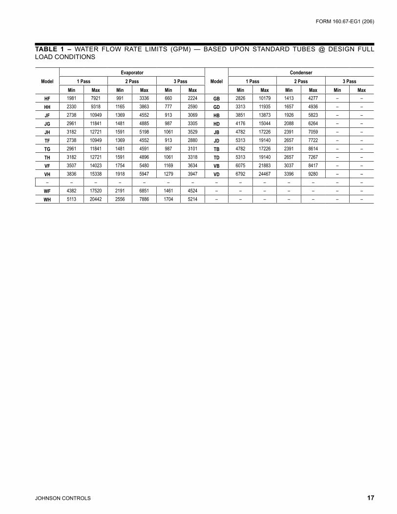
Flow Rate - For normal water chilling duty, evaporator and refrigerant condenser flow rates are permitted at water velocitylevelsintheheatexchangerstubesofbetween3 ft/sec and 12 ft/sec (0.9 m/s and 3.7 m/s). Variable flow applications are possible, however, chiller selections mustbemadeusingawater velocitywithin the rangenoted above. Variable flow in the refrigerant condenser is not recommended, as it generally raises the energy consumption of the system by keeping the refrigerant condenser pressure high in the chiller. Additionally, the rateoffoulingintherefrigerantcondenserwillincreaseat lower water velocities associated with variable flow, raisingsystemmaintenancecosts.Coolingtowerstypi-cally have narrow ranges of operation with respect to flow rates and will be more effective with full design flow. Ref. Table 1 for flow limits.
Temperature Ranges - For normal water chilling duty, leaving chilled water temperatures may be selectedbetween 38°F (3.3°C) [36°F (2.2°C) with Smart Freeze enabled] and 70°F (21°C) for water temperature ranges between 3°F and 30°F (1.7°C and 16.7°C).
Water Quality –Thepracticalandeconomicalapplica-tionofliquidchillersrequiresthatthequalityofthewater
supplyforthecondensersandevaporatorbeanalyzedbyawatertreatmentspecialist.Waterqualitymayaffecttheperformance of any chiller through corrosion, deposition of heat-resistant scale, sedimentation or organic growth. Thesewilldegradechillerperformanceandincreaseop-erating and maintenance costs. Normally, performance may be maintained by corrective water treatment andperiodiccleaningoftubes.Ifwaterconditionsexistwhichcannot be corrected by proper water treatment, it may be necessary to provide a larger allowance for fouling, and/or tospecifyspecialmaterialsofconstruction.
General Piping–Allchilledwaterandcondenserwaterpipingshouldbedesignedand installed inaccordancewith accepted piping practice. Chilled water and con-denser water pumps should be located to dischargethrough the chiller to assure positive pressure and flow through the unit. Piping should include offsets to provide flexibility and should be arranged to prevent drainage of waterfromtheevaporatorandcondenserwhenthepumpsare shut off. Piping should be adequately supported and bracedindependentlyofthechillertoavoidtheimposi-tionofstrainonchillercomponents.Hangersmustallowforalignmentof thepipe. Isolators in thepipingand inthehangersarehighlydesirableinachievingsoundandvibrationcontrol.
Convenience Considerations–Tofacilitatetheperfor-mance of routine maintenance work, some or all of the following steps may be taken by the purchaser: Heatexchangerwaterboxesareequippedwithpluggedvent and drain connections. If desired, vent and drain valvesmaybeinstalledwithorwithoutpipingtoanopendrain. Pressure gauges with stop cocks and stop valves maybeinstalledintheinletsandoutletsofthecondensersandchilledwaterlineascloseaspossibletothechiller.Anoverheadmonorailorbeammaybeusedtofacilitateservicing.
Connections – The standard chiller is designed for 150 psig (1030 kPa) design working pressure in both the chilledwaterandcondenserwatercircuits.Theconnec-tions(waternozzles)tothesecircuitsarefurnishedwithgrooves for Victaulic couplings. Piping should be arranged foreaseofdisassemblyattheunitfortubecleaning.Allwaterpipingshouldbethoroughlycleanedofalldirtanddebris before final connections are made to the chiller.
Chilled Water – A water strainer of maximum 1/8" (3 mm) perforated holes must be field-installed in the chilled water inletlineascloseaspossibletothechiller.Iflocatedcloseenough to the chiller, the chilled water pump may be pro-tectedbythesamestrainer.Thelossorseverereductionof water flow due to tube blockage could seriously impair thechillerperformanceorevenresultintubefreeze-up.

FORM 160.67-EG1 (206)
JOHNSONCONTROLS 15
Condenser Water–Thechillerisengineeredformaxi-mum efficiency at both design and part load operation by taking advantage of the colder cooling tower water temperatures which naturally occur during the wintermonths.Appreciable power savings are realized fromthesereducedheads.Theminimumenteringcondenserwatertemperatureisprovidedbythefollowingequation:
In °F: minCondWT = LChilledWT - CondRange x (PCT-Load/100) + 5 + 12 x (PctLoad/100)
In °C: minCondWT = LChilledWT - CondRange x (PCT-Load/ 100) + (5 + 12 x (PctLoad/100))/1.8where:
minCondWT = entering condenser water temperature
LChilledWT = leaving chilled water temperature
CondRange = condenser water temperature range at design.
PCTLoad = chiller load as % design
At initial startup, entering condensing water temperature may be as much as 25°F (14°C) colder than the standby chilledwatertemperatureaslongasitisabovethemini-mumenteringcondenserwatertemperatureallowed.
A water strainer of maximum 1/8" (3 mm) perforated holes is recommended to be field-installed in the refrigerant con-denserwaterinletlineascloseaspossibletothechiller.If located close enough to the chiller, the condenser water pumpmaybeprotectedbythesamestrainer.Thelossorsevere reduction of water flow due to tube blockage could seriouslyimpairthechillerperformance.
STEAM AND CONDENSATE PIPING
Turbinesupplysteamandcondensatepipingconnectionstothechilleraretobesuppliedandinstalledbythesitepiping contractor. In addition, the turbine exhaust to the steamcondensershallbeinstalledbythepipingcontrac-tor, however, the design and supply of components may besuppliedbyYORKdependingontheoptionschosen.Piping should be adequately supported and braced inde-pendentlyofthechillers.Hangersmustallowforpipingalignment at the operation temperature. Piping contractor is responsible for the fit and form of the turbine steam piping. The piping must be installed with the flanges and boltholesproperlyaligned.Theboltsshouldbeabletobe inserted without any difficulty and no force should be applied to allow the bolts to be inserted or flanges aligned. When the flange bolts are tightened, they must not impose
any force or moment on the turbine flanges. Contact your local YORK office for any additional information.
RELIEF PIPING
Refrigerant Relief
Eachchillerisequippedwithdualpressurereliefvalvesontherefrigerantcondenserandtwodualreliefvalvesonthe evaporator, or two single relief valves on the evapora-toriftheoptionalrefrigerantisolationvalvesareordered.Thedualreliefvalvesontherefrigerantcondenserareredundantandallowchangingofeithervalvewhiletheunitisfullycharged.Thepurposeofthereliefvalvesistoquickly relieve excess pressure of the refrigerant charge to the atmosphere, as a safety precaution in the event of an emergency such as fire. They are set to relieve at an internalpressureasnotedonthepressurevesseldataplate, and are provided in accordance with ASHRAE 15 safety code andASME or applicable pressure vesselcode.
Sized to the requirements of applicable codes, a vent line mustrunfromthereliefdevicetotheoutsideofthebuild-ing. This refrigerant relief piping must include a cleanable, vertical-leg dirt trap to catch vent-stack condensation. Ventpipingmustbearrangedtoavoidimposingastrainon the relief connection and should include one flexible connection.
Steam Relief
Eachsteamcondenserisequippedwithanatmosphericrelief valve, sized to relieve all the steam which can be admittedtoaturbineundermaximumpossiblefullthrottleconditions. The atmospheric relief valve is designed/selectedperHEIstandards forsteamcondensersandprovides protection for the steam turbine exhaust andexhaust trunk, as well as the steam condenser shell. Thedischargeoftheatmosphericreliefvalveshouldbepiped to direct a large volumetric flow of hot steam to a safe area, away from all personnel.
SOUND AND VIBRATION CONSIDERATIONS
AYSTMaxE chiller is not a source of objectionable sound and vibration in normal air conditioning applications.Neoprene isolation mounts are furnished as standardwitheachunit.
YST MaxE chiller sound pressure level ratings will befurnishedonrequest.
Control of sound and vibration transmission must be taken intoaccountintheequipmentroomconstructionaswellasintheselectionandinstallationoftheequipment.

16 JOHNSONCONTROLS
Application Data (continued)THERMAL INSULATION
Noappreciableoperatingeconomycanbeachievedbythermally insulating the chiller. However, the chiller's cold surfacesshouldbeinsulatedwithavaporbarrierinsula-tion sufficient to prevent condensation. A chiller can be factory-insulated with 3/4" (19 mm) or 1-1/2" (38 mm) thick insulation, as an option. This insulation will nor-mallypreventcondensationinenvironmentswithdrybulbtemperatures of 50°F to 90°F (10°C to 32°C) and relative humidities up to 75% [3/4" (19 mm) thickness] or 90% [1-1/2" (38 mm) thickness]. The insulation is painted and the surface is flexible and reasonably resistant to wear. It is intended for a chiller installed indoors and, therefore, no protectivecoveringoftheinsulationisusuallyrequired.If insulation is applied to the water boxes at the job site, itmustberemovabletopermitaccessto thetubesforroutinemaintenance.Theturbinesteamchestisfactoryinsulated with a custom fitted, fiberglass insulating blanket for protection of personnel. The blanket is removable for maintenanceaccesstotheturbine.
VENTILATION
The ASHRAE Standard 15 Safety Code for Mechanical Refrigerationrequiresthatallmachineryroomsbeventedtotheoutdoorsutilizingmechanicalventilationbyoneormore power-driven fans. This standard, plus National Fire Protection Association Standard 90A, state, local and any other related codes should be reviewed for specific requirements.SincetheYSTMaxE chiller uses steam, ventilationshouldallowfortheremovalofheatradiatedfromthesteamturbine.
In addition, the ASHRAE Standard 15 requires a refriger-antvapordetectortobeemployedforallrefrigerants.Itis to be located in an area where refrigerant from a leak would be likely to concentrate. An alarm is to be acti-vatedandthemechanicalventilationstartedatavaluenogreater than theTLV(ThresholdLimitValue)of therefrigerant.
CUSTOMER CONNECTIONS/INTERFACES (see product drawings for connection sizes)
Water/Drains
• Refrigerant condenser inlet/outlet**• Evaporator inlet/outlet• Turbine/Compressor cooling water manifold inlet/out-
let• Steam condenser inlet**/outlet• Steamcondenservacuumpumpsealwater:3.5gpm
(0.2 L/s) @ approx. 60°F (15.6 °C)• Steamcondenservacuumpumpdischargeseparator
ventanddrain• Steam condenser relief valve seal water: trickle flow• Steamcondenserreliefvalvesealwaterdrain
• Steamturbinecasingdrain• Steam turbine gland leak off drain• Steamturbinesteamringdrain• Steam condenser condensate overboard valve: [note:
approx. 20 psig (138 kPa) discharge pressure avail-ableatoutletofoverboardvalve.Ifdownstreampres-sure requirements exceed this, a custom condensate pump selection is required.]
• Steamcondenserhotwelllevelsystemdrain• Water box vents and drains - evaporator, refrigerant
condenserandsteamcondenser
**York provided pre-fabricated piping for these con-nections
Steam/Vents
• Steamturbinesteaminlet• Steam turbine steam exhaust**• Steam condenser steam inlet**• Steamcondenserreliefvalvevent• Steam turbine gland sealing steam: 150 psig (1030
kPa) max. steam supply• Steamturbineglandsealreliefvalve
**York provided pre-fabricated piping for these con-nections
Refrigerant Connections
• Refrigerant drain/charging connection• Refrigerant transfer/service connections• Refrigerantcondenserreliefvalves(s)• Evaporatorreliefvalve(s)
Air (Instrument Quality Air Source - ISA S7.3)
• Steamturbinegovernorairsupplyandbearingsealair purge: 80-150 psig (552 - 1030 kPa), approx. 13 SCFM (22 sm3/h).
• Steam condenser level control system: 20-150 psig (138 - 1030 kPa), approx. 0.5 SCFM (0.9 sm3/h).
Power
• 460V single point power connection, approximately 28.6 KVA (KD turbine) or 24.2 KVA (KG turbine).
Required Auxiliary Components (customer supplied)
• Steam inlet strainer: Full flow strainer with fine [3/64" (1.2 mm) perforations], stainless steel mesh, suitable forsteamservice.
• Steam inlet moisture separator: Steam supply toturbine must be dry & saturated for optimum effi-ciency.
• Steaminletthrottlingvalve:Manualglobevalveforinletsteamisolationandthrottling(duringstartup).Note: This valve is York supplied when the system auto-startoptionisordered.
FORM 160.67-EG1 (206)
JOHNSONCONTROLS 17
ModelEvaporator
ModelCondenser
1 Pass 2 Pass 3 Pass 1 Pass 2 Pass 3 PassMin Max Min Max Min Max Min Max Min Max Min Max
HF 1981 7921 991 3336 660 2224 GB 2826 10179 1413 4277 – –HH 2330 9318 1165 3863 777 2590 GD 3313 11935 1657 4936 – –JF 2738 10949 1369 4552 913 3069 HB 3851 13873 1926 5823 – –JG 2961 11841 1481 4885 987 3305 HD 4176 15044 2088 6264 – –JH 3182 12721 1591 5198 1061 3529 JB 4782 17226 2391 7059 – –TF 2738 10949 1369 4552 913 2880 JD 5313 19140 2657 7722 – –TG 2961 11841 1481 4591 987 3101 TB 4782 17226 2391 8614 – –TH 3182 12721 1591 4896 1061 3318 TD 5313 19140 2657 7267 – –VF 3507 14023 1754 5480 1169 3634 VB 6075 21883 3037 8417 – –VH 3836 15338 1918 5947 1279 3947 VD 6792 24467 3396 9280 – –– – – – – – – – – – – – – –
WF 4382 17520 2191 6851 1461 4524 – – – – – – –WH 5113 20442 2556 7886 1704 5214 – – – – – – –
TABLE 1 – WATER FLOW RATE LIMITS (GPM) — BASED UPON STANDARD TUBES @ DESIGN FULL LOADCONDITIONS

1� JOHNSONCONTROLS
ModelEvaporator
ModelCondenser
1 Pass 2 Pass 3 Pass 1 Pass 2 Pass 3 PassMin Max Min Max Min Max Min Max Min Max Min Max
HF 125 500 62 210 42 140 GB 178 642 89 270 – –HH 147 588 74 244 49 163 GD 209 753 105 311 – –JF 173 691 86 287 58 194 HB 243 875 121 367 – –JG 187 747 93 308 62 209 HD 263 949 132 395 – –JH 201 803 100 328 67 223 JB 302 1087 151 445 – –TF 173 691 86 270 58 182 JD 335 1208 168 487 – –TG 187 747 93 290 62 196 TB 302 1087 151 543 – –TH 201 803 100 309 67 249 TD 335 1208 168 458 – –VF 221 885 111 346 74 229 VB 383 1381 192 531 – –VH 242 988 121 375 81 249 VD 429 1544 214 585 – –
– – – – – – –WF 276 1105 138 432 92 285 – – – – – – –WF 323 1290 161 498 108 329 – – – – – – –
TABLE 1A – WATER FLOW RATE LIMITS (L/S) — BASED UPON STANDARD TUBES @ DESIGN FULL LOADCONDITIONS

FORM 160.67-EG1 (206)
JOHNSONCONTROLS 1�

20 JOHNSONCONTROLS
Application Data (continued)
TABLE 2 – AVAILABLE COMPRESSOR/SHELL/TURBINE/STEAM CONDENSER MODELS
COMPRESSOR CODE EVAPORATOR CODE CONDENSER CODE TURBINE MODEL STEAM CONDENSER MODEL
J1 HF, HH GB, GD
K2G51000090K2G51000125K2G71000090K2G71000125
29168A29168B29168C29168D
J2 HF, HH GB, GDHB, HD
KG81250090K2G71250125
31168B31168C31168D
J3 JF, JG, JH JB, JD
KG81620090K2G71620125KD71620090KD71620125
35168B35168C35168D
J4
TF, TG, TH TB, TD KD71620090KD71620125KD71750090KD71750125
33192B33192C33192D
VF, VH VB, VD
WF, WH VB, VD

FORM 160.67-EG1 (206)
JOHNSONCONTROLS 21
Dimensions (Ft. - In.) – Top Mtd. Unit
NOTES: 1. All dimensions are approximate. Certified dimensions are available on request. 2. Water nozzles can be located on either end of unit. Add 1/2" to nozzle length for flanges connections. 3. Add 1-3/4" for neoprene pads or 3/4" if neoprene pads are not supplied. 4. Approx. overall shipping height to top of compressor Casing. Steam condenser ships separately to job site.
K
ISTEAM INLET
J
NOTE 3
EVAPORATORCONDENSER
TURBINE
APPROX. OVERALL WIDTH
AP
PR
OX
. OV
ER
ALL
HE
IGH
T
STEAMCONDENSERPACKAGE
E
F
C
SEE NOTE 4
M
L
H G HNOTE 3
j COMPRESSOR UNITS
J1 COMPRESSOR (H-G SHELLS)KG STEAM TURBINE /
29168 STEAM CONDENSERDIMENSION CODE FT-INCHES
A 8'–11 1/4"B 7'–10 1/2"C 2'–2 1/4"D 1'–9"
E W/4" STEAM INLET 6'–11 3/4"E W/6" STEAM INLET 6'–10 1/2"
F 15'–9"G 14'–0"I 6'–8 1/4"
J W/4" STEAM INLET 1'–9 3/16"J W/6" STEAM INLET 2'–2 3/16"
K 0'–3 3/4"L 14'–7"M 10"–0"
J2 COMPRESSORKG STEAM TURBINE /
31168 STEAM CONDENSERSHELL CODE H-G H-H
DIMENSION CODE FT-INCHES FT-INCHESA 8'–11 1/4" 9'–2"B 7'–10 1/2" 8'–2 1/2"C 2'–2 1/4" 2'–2 1/4"D 1'–9" 1'–11'
E W/4" STEAM INLET 6'–11 3/4" 6'–14 3/4"E W/6" STEAM INLET 6'–10 1/2" 6'–13 1/2"
F 15'–11" 16'–3"G 14'–0" 14'–0"I 6'–8 1/4" 6'–8 3/8"
J W/4" STEAM INLET 1'–9 3/16" 1'–9 3/16"J W/6" STEAM INLET 2'–2 3/16" 2'–2 3/16"
K 0'–3 3/4" 0'–3 3/4"L 14'–8 15/16" 15'–0 15/16"M 10'–0" 10"–3"

22 JOHNSONCONTROLS
�
�
�
�
�
�
���������������������������������������������������
MODEL N O P Q R S
H-G-J1 14'-8" 7'-4" 8'-1-1/2" 2'-3-3/4" 10" 9"
H-G-J2 14'-8" 7'-4" 8'-1-1/2" 2'-3-3/4" 10" 9"
H-H-J2 14'-8" 7'-4" 8'-5-1/2" 2'-3-3/4" 10" 9"
J-J-J3 14'-8" 7'-4" 9'-4" 2'-7" 10" 9"
T-T-J4 16'-8" 8'-4" 9'-4" 2'-7" 10" 9"
V-V-J4 16'-8" 8'-4" 9'-9" 2'-7" 10" 9"
W-V-J4 16'-9" 8'-4-1/2 10'-3" 2'-10 10" 9"
Dimensions (Ft. - In.) – Top Mtd. Unit - Cont.
TOP MOUNTED CHILLER FOOTPRINT

FORM 160.67-EG1 (206)
JOHNSONCONTROLS 23
J3 COMPRESSOR (J-J SHELLS)35168 STEAM CONDENSER
DIMENSION CODE KG STEAM TURBINE KD STEAM TURBINEFT-INCHES FT-INCHES
A 10'–0" 10'–2"B 9'–1" 9'–1"C 2'–5-1/2" 2'–5-1/2"D 2'-1" 2'–1"
E W/4" STEAM INLET 7'–8-3/4" 7'–7-1/2"E W/6" STEAM INLET 7'–7-1/2" 7'–7-1/2"
F 17'–7" 17'–7"G 14'–0" 14'–0"I 6'–7-1/2" TBD
J W/4" STEAM INLET 1'–9-3/16" 2'–5-1/4"J W/6" STEAM INLET 2'–2-3/16" 2'–5-7/16"
K 0'–4-1/2" 0'–4-1/2"L 15'–10" 15'–10"M 11'–0" 11'–0"
J4 COMPRESSORKD STEAM TURBINE / 33192 STEAM CONDENSER
SHELL CODE T-T V-V W-VDIMENSION CODE FT-INCHES FT-INCHES FT-INCHES
A 10'–2" 10'–5" 10'–9"B 9'–1" 9'–6" 9'–11"C 2'–5-1/2" 2'–5-1/2" 2'–8"D 2'–1" 2'–3-1/2" 2'–3-1/2"
E W/4" STEAM INLET 7'–9-1/2" 7'–11-1/2" 8'–2"E W/6" STEAM INLET 7'–9-1/2" 7'–11-1/2" 8'–2"
F 17'–4" 17'–9 17'–9"G 16'–0" 16'–0" 16'–0"I TBD TBD TBD
J W/4" STEAM INLET 2'–5-1/4" 2'–5-1/4" 2'–5-1/4"J W/6" STEAM INLET 2'–5-7/16" 2'–5-7/16" 2'–5-7/16"
K 0'–4-1/2" 0'–4-1/2" 0'–4"L 16'–0-1/8" 16'–5-1/8" 16'–5-1/8"M 11'–2" 11'–4" 11'–6"
DIMENSION "H" FOR ALL J COMPRESSOR MODELSSTEAM CONDENSER MODEL 29168
SHELL CODE 1 PASS REFRIG. COND. FT-IN.
2 PASS REFRIG. COND. FT-IN.
H-G 26-15/16" 25-5/16"STEAM CONDENSER MODEL 31168
SHELL CODE 1 PASS REFRIG. COND. FT-IN.
2 PASS REFRIG. COND. FT-IN.
H-G 27-5/16" 25-11/16"H-H 31-11/16" 27-13/16"
STEAM CONDENSER MODEL 35168SHELL CODE 1 PASS REFRIG.
COND. FT-IN.2 PASS REFRIG.
COND. FT-IN.J-J 32-3/16" 28-5/16"
STEAM CONDENSER MODEL 33192SHELL CODE 1 PASS REFRIG.
COND. FT-IN.2 PASS REFRIG.
COND. FT-IN.T-T 31-15/16" 28-1/16"V-V 31-15/16" 29-5/8"W-V 31-15/16" 29-5/8"

24 JOHNSONCONTROLS
FRONT
OF
UNIT
FRONT
OF
UNIT
FRONT
OF
UNIT
COMPRESSOR END TURBINE END
COMPRESSOR END TURBINE END
COMPRESSOR END TURBINE END
FLOOR
LINE
FLOOR
LINE
FLOOR
LINE
AA AA
BB BB
BB BB
FF
FF
FF FF
FF
FF1"
1"
1" 1"
1"
1"
A
B
F N
C J K
H
EE EE EE EE
1-PASS
2-PASS
3-PASS
Dimensions (Eng.) – Evap. Compact Water BoxesEVAPORATORS – COMPACT WATER BOXES – j COMPRESSOR UNITS
NOTES: 1. Standard water nozzles are furnished as welding stub-outs with Victaulic grooves, allowing the option of welding, flanges, or use of Victaulic
couplings. Factory-installed, class 150 (ANSI B16.5, round slip-on, forged carbon steel with 1/16" raised face), water flanged nozzles are optional (add 1/2" to nozzle length). Companion flanges, nuts, bolts, and gaskets are not furnished.
2. Add 1" if neoprene pads are supplied. 3. One-, two- and three-pass nozzle arrangements are available only in pairs shown and for all shell codes. Any pair of evaporator nozzles may
beusedincombinationwithanypairofcondensernozzles. 4. Connected piping should allow for removal of compact water boxes for tube access and cleaning.
NOZZLEARRANGEMENTS
NO. OFPASSES
EVAPORATOR
IN OUT
1A HH A
NOZZLEARRANGEMENTS
NO. OFPASSES
EVAPORATOR
IN OUT
2
B CC BJ KK J
NOZZLEARRANGEMENTS
NO. OFPASSES
EVAPORATORIN OUT
3F NN F
EVAP.SHELLCODE
NOZZLE PIPE SIZE EVAPORATORNOZZLE DIMENSIONS
NO. OF PASSES 1-PASS 2-PASS 3-PASS1 2 3 AA2 FF BB2 EE FF BB2 FF
HF 16" 12" 10" 2'–0-3/4" 2'–2-1/4" 2'–0-3/4" 11" 2'–2-1/4" 2'–0-3/4" 2'–2-1/4"HH 16" 12" 10" 2'–1-1/2" 2'–2-1/4" 2'–1-1/2" 11" 2'–2-1/4" 2'–1-1/2" 2'–2-1/4"J 18" 14" 12" 2'–1-3/4" 2'–5-1/2" 2'–1-3/4" 11" 2'–5-1/2" 2'–1-3/4" 2'–5-1/2"T 18" 14" 12" 2'–1-3/4" 2'–5-1/2" 2'–1-3/4" 11" 2'–5-1/2" 2'–1-3/4" 2'–5-1/2"V 20" 16" 12" 2'–5-1/4" 2'–5-1/2" 2'–5-1/4" 1'–1" 2'–5-1/2" 2'–5-1/4" 2'–5-1/2"W 20" 18" 14" 2'–7-1/4" 2'–8" 2'–7-1/4" 1'–3" 2'–8" 2'–7-1/4" 2'–8"

FORM 160.67-EG1 (206)
JOHNSONCONTROLS 25
Dimensions (Eng.) – Evap. Marine Water BoxesEVAPORATORS – MARINE WATER BOXES – j COMPRESSOR UNITS
A
B
3
TURBINE ENDCOMPRESSOR END FLOOR LINE
2
IN
OUT
D C
1"
FRONT OF UNIT2-PASS
LD07987
NOTES: 1. All dimensions are approximate. Certified dimensions are available upon request. 2. Standard water nozzles are Schedule 40 pipe size, furnished as welding stub-outs with Victaulic grooves, allowing the option of welding,
flanges, or use of Victaulic couplings. Factory-installed, class 150 (ANSI B16.5, round slip-on, forged carbon steel with 1/16" raised face), water flanged nozzles are optional (add 1/2" to nozzle length). Companion flanges, nuts, bolts, and gaskets are not furnished.
3. CompactwaterboxesononeheatexchangermaybeusedwithMarineWaterBoxesontheotherheatexchanger. 4. Water must enter the water box through the bottom connection to achieve rated performance. 5. Add 1" if neoprene pads are supplied.
G
K
(2-PASS
RETURN HEAD)
H
LD08639
NOZZLE HEAD2 PASS
RETURN HEAD
G H
COMPR.CODE
EVAP-CONDSHELL CODE
G H
J1, J2H-G 1'–2 3/4" 1'–11 3/4"H-H 1'–2 3/4" 1'–11 3/4"J-J 1'–2 3/4" 1'–11 3/4"
J3, J4T-T 1'–2 3/4" 1'–11 3/4"V-V 1'–2 3/4" 1'–11 3/4"W-V 1'–4 1/2" 2'–0 3/4"
EVAP.SHELLCODE
EVAPORATOR NOZZLE DIMENSIONS2-PASS
A5 B5 C DHF 4'–5-1/4" 2'–2-3/4" 2'–7-1/4" 2'–2-1/4"HH 4'–6" 1'–8-1/4" 2'–7-1/4" 2'–2-1/4"J 3'–11-3/4" 1'–9-3/4" 2'–10-1/4" 2'–5-1/2"T 3'–11-3/4" 1'–9-3/4" 2'–10-1/4" 2'–5-1/2"V 4'–3-1/4" 2'–1-1/2" 2'–10-1/4" 2'–5-1/2"W 4'–6-1/2" 2'–3-1/2" 3'–2" 2'–6"
EVAPORATOR2-PASS
IN OUT2 3
EVAPORATORSHELLCODE
NOZZLE PIPE SIZENO. OF PASSES
2H 12"J 14"T 14"V 16"W 18"
EVAPORATORSHELLCODE
EVAPORATOR NOZZLEDIMENSIONS (2-PASS)
G H KH 11-3/8" 2'–0-3/4" 1'–2-3/4"J 1'–0-3/8" 2'–2-3/4" 1'–2-3/4"T 1'–0-3/8" 2'–2-3/4" 1'–2-3/4"V 1'–2" 2'–6" 1'–2-3/4"W 1'–3" 2'–6" 1'–4-1/2"

26 JOHNSONCONTROLS
CONDENSERS – MARINE WATER BOXES – j COMPRESSOR UNITS
LD07991
See Notes on page 28.
D
18
A 17
C
B
SEE NOTE 6
B
C
A12
13
D
1" 1" 1"1"
1"1"
COMPRESSOR END TURBINE END
COMPRESSOR END COMPRESSOR END
COMPRESSOR END
11 16
D D
FLOOR LINE FLOOR LINE
FLOOR LINE FLOOR LINE
A
11 16SEE NOTE 6
D D
A
FRONT OF UNIT FRONT OF UNIT
FRONT OF UNIT FRONT OF UNIT
1-PASS
2-PASS
1"1"
TURBINE END TURBINE END
TURBINE END
IN OUT
OUT
IN IN
OUT
OUT IN
COND.SHELLCODE
CONDENSER NOZZLE DIMENSIONS1-PASS 2-PASS
A5 D A5 B5 C DG 5'–9-3/4" 1'–9" 5'–9-3/4" 2'–8-3/4" 2'–5" 1'–9"H 5'–11" 1'–11" 5'–10-1/4" 2'–0-3/4" 2'–1" 1'–11"J 6'–3-3/8" 2'–1" 6'–2-3/8" 2'–1-1/2" 2'–1-1/8" 2'–1"T 6'–3-3/8" 2'–1" 6'–2-3/8" 2'–1-1/2" 2'–1-1/8" 2'–1"V 6'–8-3/4" 2'–3-1/2" 6'–8-1/8" 2'–1-3/4" 2'–5-3/8" 2'–3-1/2"
Dimensions (Eng.) – Cond. Marine Water Boxes

FORM 160.67-EG1 (206)
JOHNSONCONTROLS 27
CONDENSER1-PASS
IN OUT11 1616 11
CONDENSER2-PASS
IN OUT12 1317 18
CONDENSERSHELLCODE
COND. NOZZLEDIMENSIONS (1-PASS)
G HG 1'–1 1/4" 2'–4 3/�"H 1'–3 1/2" 2'–� 3/4"j 1'–3 1/2" 2'–� 7/�"T 1'–3 1/2" 2'–� 7/�"V 1'–3 1/2" 2'–� 3/�"
NOTES (see table on page 27): 1. All dimensions are approximate. Certified dimensions are available upon request. 2. Standard water nozzles are Schedule 40 pipe size, furnished as welding stub-outs with Victaulic grooves, allowing the option of welding, flanges,
or use of Victaulic couplings. Factory-installed, class 150 (ANSI B16.5, round slip-on, forged carbon steel with 1/16" raised face), water flanged nozzles are optional (add 1/2" to nozzle length). Companion flanges, nuts, bolts, and gaskets are not furnished.
3. One-andtwo-passnozzlearrangementsareavailableonlyinpairsshownandforallshellcodes.Anypairofevaporatornozzlesmaybeusedincombinationwithanypairofcondensernozzles.CompactwaterboxesononeheatexchangermaybeusedwithMarineWaterBoxesontheotherheatexchanger.
4. Condenser water must enter the water box through the bottom connection for proper operation of the sub-cooler to achieve rated perfor-mance.
5. Add 1" if neoprene pads are supplied. 6. “G” Condenser Water Boxes are square; other codes are round as shown.
TUBE
SHEET
G
H
TUBE
SHEET
(2-PASS
RETURN HEAD)K
Dimensions (Eng.) – Nozzle Arrangements
COND.SHELLCODE
NOZZLE PIPE SIZENO. OF PASSES
1 2G 16" 14"H 20" 16"J 20" 16"T 20" 16"V 20" 18"
CONDENSERSHELLCODE
COND. NOZZLEDIMENSIONS (2-PASS)
G H KG 1'–0 1/4" 2'–2 3/8" 0'–5 7/8"H 1'–1 5/8" 2'–5" 0'–11 5/8"J 1'–1 5/8" 2'–5 1/8" 1'–0 1/2"T 1'–1 5/8" 2'–5 1/8" 1'–0 1/2"V 1'–2 1/4" 2'–6 3/4" 1'–1 5/8"

2� JOHNSONCONTROLS
Dimensions (Ft. - In.) – Floor Mtd. Unit
�������������
�
�
�
�
�������������������������������������������
�
�
FLOOR MOUNTED UNIT DIMENSIONS
DIMENSION FT-IN
H-G-J1/J2-KG 29168 STEAM
COND 20" X 20" EXHAUST
H-H-J2-KG 31168 STEAM
COND 24" X 20" EXHAUST
J-J-J3-KG 35168 STEAM
COND 24" X 24" EXHAUST
J-J-J3-KD 35168 STEAM
COND 24" X 24" EXHAUST
T-T-J4-KD 33192 STEAM
COND 24" X 24" EXHAUST
V-V-J4-KD 33192 STEAM
COND 24" X 24" EXHAUST
W-V-J4-KD 33192 STEAM
COND 24" X 24" EXHAUST
A 8' 8' 8'-6" 8'-6" 8'-6" 8'-6" 8'-8" B 9'–6-3/4" 9'–6-3/4" 10'–4-1/4" 10'–8-1/4" 10'–10-1/4" 11'–1/4" 11'–2-3/4" C 13'–6" 14'–6" 15' 15'–4" 15'–6" 15'–8" 15'–10" D 6'–11-3/8" 7'–1-3/8" 7'–5-3/8" 7'–5-3/8" 7'–3-3/8" 7'–3-3/8" 7'–3-3/8" E 4'–3/4" 4'–3/4" 3'–11-1/2" 3'–11-1/2" 3'–11-1/2" 3'–11-1/2" 3'–11" F 15'–4" 15'–8" 17'–1" 17'–1" 17'–1" 17'–6" 17'–10" G 7'–2-1/2" 7'–2-1/2" 7'–2-1/2" 7'–2-1/2" 8'–2-1/2" 8'–2-1/2" 8'–2-1/2" H 14'–5" 14'–5" 14'–5" 14'–5" 16'–5" 16'–5" 16'–5" J 3'–4" 3'–4" 3'–10" 3'–10" 3'–10" 3'–10" 3'–10" K 7'–1-1/2" 7'–1-1/2" 7'–1-1/2" 7'–1-1/2" 8'–1-1/2" 8'–1-1/2" 8'–1-1/2" L 14'–3" 14'–3" 14'–3" 14'–3" 16'–3-1/2" 16'–3-1/2" 16'–3-1/2" M 1' 1' 1'–2" 1'–2" 1'–2" 1'–2" 1'–2" N 2' 2' 2'–4" 2'–4" 2'–4" 2'–4" 2'–4" P 1'–7" 1'–7" 1'–9" 1'–9" 1'–9" 1'–9" 1'–9" Q 14'–6" 14'–6" 14'–8" 14'–8" 16'–8" 16'–8" 16'–8-1/2" R 7'–3" 7'–3" 7'–4" 7'–4" 8'–4" 8'–4" 8'–4-1/2" S 7'–10-1/2" 8'–2-1/2" 9'–4" 9'–4" 9'–4" 9'–9" 10'–2" T 2'–2-1/4" 2'–2-1/4" 2'–7" 2'–7" 2'–7" 2'–7" 2'–9-1/2" U 8" 8" 10" 10" 10" 10" 10" V 6" 6" 9" 9" 9" 9" 9"

FORM 160.67-EG1 (206)
JOHNSONCONTROLS 2�
Form 3 Shipment Dimensions

30 JOHNSONCONTROLS
Form 7 Shipment Dimensions

FORM 160.67-EG1 (206)
JOHNSONCONTROLS 31
J3 COMPRESSOR (J-J SHELLS)35168 STEAM CONDENSER
DIMENSION CODEKG STEAM TUR-
BINEKD STEAM TUR-
BINEFT-INCHES FT-INCHES
A 10'–0" 10'–2"B 9'–1" 9'–1"C 2'–5-1/2" 2'–5-1/2"D 2'-1" 2'–1"
E W/4" STEAM INLET 7'–8-3/4" 7'–7-1/2"
E W/6" STEAM INLET 7'–7-1/2" 7'–7-1/2"
F 17'–7" 17'–7"G 14'–0" 14'–0"I 6'–7-1/2" TBD
J W/4" STEAM INLET 1'–9-3/16" 2'–5-1/4"
J4 COMPRESSORKD STEAM TURBINE / 33192 STEAM CONDENSER
SHELL CODE T-T V-V W-VDIMENSION CODE FT-INCHES FT-INCHES FT-INCHES
A 10'–2" 10'–5" 10'–9"B 9'–1" 9'–6" 9'–11"C 2'–5-1/2" 2'–5-1/2" 2'–8"D 2'–1" 2'–3-1/2" 2'–3-1/2"
E W/4" STEAM INLET 7'–9-1/2" 7'–11-1/2" 8'–2"E W/6" STEAM INLET 7'–9-1/2" 7'–11-1/2" 8'–2"
F 17'–4" 17'–9 17'–9"G 16'–0" 16'–0" 16'–0"I TBD TBD TBD
J W/4" STEAM INLET 2'–5-1/4" 2'–5-1/4" 2'–5-1/4"J W/6" STEAM INLET 2'–5-7/16" 2'–5-7/16" 2'–5-7/16"
K 0'–4-1/2" 0'–4-1/2" 0'–4"L 16'–0-1/8" 16'–5-1/8" 16'–5-1/8"M 11'–2" 11'–4" 11'–6"
DIMENSION "H" FOR ALL J COMPRESSOR MODELSSTEAM CONDENSER MODEL 29168
1 PASS REFRIG. COND.
2 PASS REFRIG. COND.
SHELL CODE FT-INCHES FT-INCHESH-G 26-15/16" 25-5/16"
STEAM CONDENSER MODEL 311681 PASS REFRIG.
COND.2 PASS REFRIG.
COND.SHELL CODE FT-INCHES FT-INCHES
H-G 27-5/16" 25-11/16"H-H 31-11/16" 27-13/16"
STEAM CONDENSER MODEL 351681 PASS REFRIG.
COND.2 PASS REFRIG.
COND.SHELL CODE FT-INCHES FT-INCHES
J-J 32-3/16" 28-5/16"STEAM CONDENSER MODEL 33192
1 PASS REFRIG. COND.
2 PASS REFRIG. COND.
SHELL CODE FT-INCHES FT-INCHEST-T 31-15/16" 28-1/16"V-V 31-15/16" 29-5/8"W-V 31-15/16" 29-5/8"

32 JOHNSONCONTROLS
B
A
OUTLETRELIEFVALVE EXHAUSTIN
INLET
C
D
APPROX. OVERALLWIDTH
E
LD08001
Steam Condenser (Eng.)
STEAM CONDENSER MODEL29168 31168 35168 33192
DIMENSION CODE FT-INCHES FT-INCHES FT-INCHES FT-INCHESB 14'–5" 14'–5" 14'–5" 16'–5"C 3'–4" 3'–4" 3'–10" 3'–10"D 4'–0" 4'–0" 4'–4" 4'–3"E 6'–11-3/8" 7'–1-3/8" 7'–5-3/8" 7'–3-3/8"F 2'–0" 2'–0" 2'–4" 2'–4"G 1'–0" 1'–0" 1'–2" 1'–2"H 1'–7" 1'–7" 1'–9" 1'–9"I 3'–4" 3'–4" 3'–10" 3'–10"J 14'–3" 14'–3" 14'–3" 16'–3"K 14'–5" 14'–5" 14'–5" 16'–5"
DIMENSION "A" FOR ALL MODELS
Model 1 Pass Refrig. Cond. 2 Pass Refrig. Cond.ft-inches ft-inches
29168 18–5-7/8" 18'–2-5/8"31168 w/H-G shells 18'–6-5/8" 18'–3-3/8"31168 w/H-H shells 19'–3-3/8" 18'–7-5/8"
35168 19'–4-3/8" 18'–8-5/8"33192 w/T-T shells 21'–3-7/8" 20'–8-1/8"33192 w/V-V shells 21'–3-7/8" 20'–11-1/4"33192 w/W-V shells 21'–3-7/8" 20'–11-1/4"

FORM 160.67-EG1 (206)
JOHNSONCONTROLS 33
Dimensions (mm) – Unitj COMPRESSOR UNITS
NOTES: 1. All dimensions are approximate. Certified dimensions are available on request. 2. Water nozzles can be located on either end of unit. Add 13mm to nozzle length for flanges connections. 3. Add 44mm for neoprene pads or 19mm if neoprene pads are not supplied.
K
ISTEAM INLET
J
NOTE 3
EVAPORATORCONDENSER
TURBINE
APPROX. OVERALL WIDTH
AP
PR
OX
. OV
ER
ALL
HE
IGH
T
STEAMCONDENSERPACKAGE
E
F
C
SEE NOTE 4
M
L
H G HNOTE 3
LD08000
J1 COMPRESSOR (H-G SHELLS) KG STEAM TURBINE / 29168 STEAM CONDENSER
DIMENSION CODE MM A 2725B 2401C 667D 534
E W/4 STEAM INLET " 2128E W/6 STEAM INLET " 2096
F 4801G 4268I 2039
J W/4 STEAM INLET " 539J W/6 STEAM INLET " 6
K 96L 4445M 3048
J2 COMPRESSOR KG STEAM TURBINE / 31168 STEAM CONDENSER
SHELL CODE H-G H-H DIMENSION CODE MM MM
A 2725 2794B 2401 2502C 667 667D 534 585
E W/4 STEAM INLET " 2128 2204E W/6 STEAM INLET " 2096 2172
F 4852 4953G 4268 4268I 2039 2042
J W/4 STEAM INLET " 539 539J W/6 STEAM INLET " 6 6
K 96 96L 4495 4596M 3048 3124

34 JOHNSONCONTROLS
�
�
�
�
�
�
���������������������������������������������������
MODEL N O P Q R SH-G-J1 4470 2235 2477 705 254 229H-G-J2 4470 2235 2477 705 254 229H-H-J2 4470 2235 2578 705 254 229J-J-J3 4470 2235 2845 785 254 229T-T-J4 5080 2540 2845 785 254 229V-V-J4 5080 2540 2972 785 254 229W-V-J4 5105 2553 3124 864 279 254

FORM 160.67-EG1 (206)
JOHNSONCONTROLS 35
Dimensions (mm) – UnitJ3 COMPRESSOR (J-J SHELLS)
35168 STEAM CONDENSER KG STEAM TURBINE KD STEAM TURBINE
DIMENSION CODE MM MM A 3048 3099B 2769 2769C 750 750D 635 635
E W/4 STEAM INLET " 2356 2325E W/6 STEAM INLET " 2325 2325
F 5360 5360G 4268 4268I 2020 TBD
J W/4 STEAM INLET " 539 743J W/6 STEAM INLET " 6 748
K 115 115L 4826 4826M 3353 3353
J4 COMPRESSOR KD STEAM TURBINE / 33192 STEAM CONDENSER
SHELL CODE T-T V-V W-V DIMENSION CODE MM MM MM
A 3099 3175 3277B 2769 2896 3023C 750 750 813D 635 699 699
E W/4 STEAM INLET " 2375 2426 2490E W/6 STEAM INLET " 2375 2426 2490
F 5284 5411 5411G 4877 4877 4877I TBD TBD TBD
J W/4 STEAM INLET " 743 743 743J W/6 STEAM INLET " 748 748 748
K 115 115 102L 4880 5007 5007 M 3404 3454 3505
DIMENSION H" FOR ALL J COMPRESSOR MODELS " STEAM CONDENSER MODEL 29168
1 PASS REFRIG. COND. 2 PASS REFRIG. COND. SHELL CODE MM MM
H-G 685 643STEAM CONDENSER MODEL 31168
1 PASS REFRIG. COND. 2 PASS REFRIG. COND. SHELL CODE MM MM
H-G 694 653H-H 805 707
STEAM CONDENSER MODEL 35168 1 PASS REFRIG. COND. 2 PASS REFRIG. COND.
SHELL CODE MM MM J-J 818 720
STEAM CONDENSER MODEL 33192 1 PASS REFRIG. COND. 2 PASS REFRIG. COND.
SHELL CODE MM MM T-T 812 713V-V 812 753W-V 812 753

36 JOHNSONCONTROLS
FRONTOF
UNIT
FRONTOF
UNIT
FRONTOF
UNIT
COMPRESSOR END TURBINEEND
COMPRESSOR END TURBINEEND
COMPRESSOR END TURBINEEND
FLOORLINE
FLOORLINE
FLOORLINE
AA AA
BB BB
BB BB
FF
FF
FF FF
FF
FF25
25
1" 1"
25
25
A
B
F N
C J K
H
EE EE EE EE
1-PASS
2-PASS
3-PASS
Dimensions (mm) – Nozzle ArrangementsEVAPORATORS – COMPACT WATER BOXES – j COMPRESSOR UNITS
LD07990A
NOZZLE ARRANGEMENTS NO. OF EVAPORATOR PASSES IN OUT 3 F N N F
EVAPORATOR EVAP. NOZZLE PIPE SIZE NOZZLE DIMENSIONS (mm) SHELL NO. OF PASSES 1-PASS 2-PASS 3-PASS CODE 1 2 3 AA2 F F BB2 EE FF BB2 FF H F 16" 12" 10" 629 667 629 279 667 629 667 HH 16" 12" 10" 648 667 648 279 667 648 667 j 18" 14" 12" 654 749 654 279 749 654 749 T 18" 14" 12" 654 749 654 279 749 654 749 V 20" 16" 12" 743 749 743 330 749 743 749 W 20" 18" 14" 794 813 794 381 813 794 813
NOZZLE ARRANGEMENTS NO. OF EVAPORATOR PASSES IN OUT 1 A H H A
NOZZLE ARRANGEMENTS NO. OF EVAPORATOR PASSES IN OUT B C 2 C B J K K J
NOTES: 1. Standard water nozzles are furnished as welding stub-outs with Victaulic grooves, allowing the option of welding, flanges, or use of Victaulic
couplings. Factory-installed, class 150 (ANSI B16.5, round slip-on, forged carbon steel with 1.6 mm raised face), water flanged nozzles are optional (add 13 mm to nozzle length). Companion flanges, nuts, bolts, and gaskets are not furnished.
2. Add 25 mm if neoprene pads are supplied. 3. One-, two- and three-pass nozzle arrangements are available only in pairs shown and for all shell codes. Any pair of evaporator nozzles may
beusedincombinationwithanypairofcondensernozzles. 4. Connected piping should allow for removal of compact water boxes for tube access and cleaning.

FORM 160.67-EG1 (206)
JOHNSONCONTROLS 37
A
B
3
TURBINE ENDCOMPRESSOR END FLOOR LINE
2
IN
OUT
D C
25
FRONT OF UNIT2-PASS
EVAPORATORS – MARINE WATER BOXES – j COMPRESSOR UNITS
LD07987A
EVAP. EVAPORATOR NOZZLE DIMENSIONS (mm) SHELL 2-PASS CODE A5 B5 C D H F 1,353 679 794 667 H H 1,372 514 794 667 j 1,213 552 870 749 T 1,213 552 870 749 V 1,302 648 870 749 W 1,384 698 965 762
EVAPORATOR NOZZLE PIPE SIZE SHELL NO. OF PASSES CODE 2 H 12" j 14" T 14" V 16" W 18"
EVAPORATOR 2-PASS IN OUT
2 3
NOTES: 1. All dimensions are approximate. Certified dimensions are available upon request. 2. Standard water nozzles are Schedule 40 pipe size, furnished as welding stub-outs with Victaulic grooves, allowing the option of welding, flanges,
or use of Victaulic couplings. Factory-installed, class 150 (ANSI B16.5, round slip-on, forged carbon steel with 1.6 mm raised face), water flanged nozzles are optional (add 13 mm to nozzle length). Companion flanges, nuts, bolts, and gaskets are not furnished.
3. Anypairofevaporatornozzlesmaybeusedincombinationwithanypairofcondensernozzles.CompactwaterboxesononeheatexchangermaybeusedwithMarineWaterBoxesontheotherheatexchanger.
4. Water must enter the water box through the bottom connection to achieve rated performance. 5. Add 25 mm if neoprene pads are supplied.
EVAPORATOR EVAPORATOR NOZZLE SHELL DIMENSIONS (2-PASS) CODE G H K H 289 629 375 j 314 679 375 T 314 679 375 V 356 762 375 W 381 762 419
LD07999
G
K
(2-PASS
RETURN HEAD)
H
COMPR. EVAP-COND CODE SHELL CODE G H
j1, j2 H-G 375 603
H-H 375 603 j-j 375 603 j3, j4 T-T 375 603 V-V 375 603 W-V 419 629
LD08639
NOZZLE HEAD2 PASS
RETURN HEAD
G H

3� JOHNSONCONTROLS
CONDENSERS – MARINE WATER BOXES – j COMPRESSOR UNITS
COND. CONDENSER NOZZLE DIMENSIONS SHELL 1-PASS 2-PASS CODE A5 D A5 B5 C D G 1,772 533 1,772 832 737 533 H 1,803 584 1,784 629 635 584 j 1,915 635 1,889 648 638 635 T 1,915 635 1,889 648 638 635 V 2,051 699 2,035 654 746 699
LD07993
See Notes on page 40.
Dimensions (mm) – Nozzle Arrangements
D
18
A 17
C
B
SEENOTE6
B
C
A12
13
D
25 25 2525
2525
COMPRESSOR END TURBINEEND
COMPRESSOR END COMPRESSOR END
COMPRESSOR END
11 16
D D
FLOORLINE FLOORLINE
FLOORLINE FLOORLINE
A
11 16SEENOTE6
D D
A
FRONTOFUNIT FRONTOFUNIT
FRONTOFUNIT FRONTOFUNIT
1-PASS
2-PASS
2525
TURBINEEND TURBINEEND
TURBINEEND

FORM 160.67-EG1 (206)
JOHNSONCONTROLS 3�
CONDENSER 1-PASS IN OUT
11 16 16 11
CONDENSER 2-PASS IN OUT
12 13 17 18
COND. NOZZLE PIPE SIZE SHELL NO. OF PASSES CODE 1 2 G 16" 14" H 20" 16" j 20" 16" T 20" 16" V 20" 18"
CONDENSER COND. NOZZLE SHELL DIMENSIONS (2-PASS) CODE G H K G 311 670 149 H 346 737 295 j 346 740 318 T 346 740 318 V 362 781 346
CONDENSER COND. NOZZLE SHELL DIMENSIONS (1-PASS) CODE G H G 337 721 H 394 832 j 394 835 T 394 835 V 394 848
NOTES (see Table on page 3�): 1. All dimensions are approximate. Certified dimensions are available upon request. 2. Standard water nozzles are Schedule 40 pipe size, furnished as welding stub-outs with Victaulic grooves, allowing the option of welding,
flanges, or use of Victaulic couplings. Factory-installed, class 150 (ANSI B16.5, round slip-on, forged carbon steel with 1.6 mm raised face), water flanged nozzles are optional (add 13 mm to nozzle length). Companion flanges, nuts, bolts, and gaskets are not furnished.
3. One-andtwo-passnozzlearrangementsareavailableonlyinpairsshownandforallshellcodes.Anypairofevaporatornozzlesmaybeusedincombinationwithanypairofcondensernozzles.CompactwaterboxesononeheatexchangermaybeusedwithMarineWaterBoxesontheotherheatexchanger.
4. Condenser water must enter the water box through the bottom connection for proper operation of the sub-cooler to achieve rated perfor-mance.
5. Add 25 mm if neoprene pads are supplied.
TUBE
SHEET
G
H
TUBE
SHEET
(2-PASS
RETURN HEAD)K
LD07183

40 JOHNSONCONTROLS
�������������
�
�
�
�
�������������������������������������������
�
�
FLOOR MOUNTED UNIT DIMENSIONS
DIMENSION MM
H-G-J1/J2-KG 29168 STEAM
COND 20 X 20"
EXHAUST "
H-H-J2-KG 31168 STEAM
COND 24 X 20"
EXHAUST "
J-J-J3-KG 35168 STEAM
COND 24 X 24"
EXHAUST "
J-J-J3-KD 35168 STEAM
COND 24 X 24"
EXHAUST "
T-T-J4-KD 33192 STEAM
COND 24 X 24"
EXHAUST "
V-V-J4-KD 33192 STEAM
COND 24 X 24"
EXHAUST "
W-V-J4-KD 33192 STEAM
COND 24 X 24" EX-
HAUST "A 2438 2438 2591 2591 2591 2591 2642B 2915 3042 3156 3258 3308 3359 3423C 4115 4420 4572 4674 4724 4775 4826D 2118 2169 2270 2270 2219 2219 2219E 1238 1238 1207 1207 1207 1207 1194F 4674 4775 5207 5207 5207 5334 5436G 2197 2197 2197 2197 2502 2502 2502H 4394 4394 4394 4394 5004 5004 5004J 1016 1016 1168 1168 1168 1168 1168K 2172 2172 2172 2172 2477 2477 2477L 4343 4343 4343 4343 4953 4953 4953M 305 305 356 356 356 356 356N 610 610 711 711 711 711 711P 483 483 533 533 533 533 533Q 4470 4470 4470 4470 5080 5080 5105R 2235 2235 2235 2235 2540 2540 2553S 2477 2477 2578 2845 2845 2972 3124T 705 705 705 787 787 787 864U 3048 3048 3048 3048 3048 3048 3353V 2743 2743 2743 2743 2743 2743 3048
Dimensions (mm) – Floor Mtd. Unit

FORM 160.67-EG1 (206)
JOHNSONCONTROLS 41

42 JOHNSONCONTROLS
Dimensions (Mm) – Floor Td. Unit - Continued

FORM 160.67-EG1 (206)
JOHNSONCONTROLS 43

44 JOHNSONCONTROLS
B
A
OUTLETRELIEFVALVE EXHAUSTIN
INLET
C
D
APPROX. OVERALLWIDTH
E
LD08001
Steam Condenser (mm)
STEAM CONDENSER MODEL29168 31168 35168 33192
DIMENSION CODE MM MM MM MMB 4395 4395 4395 5004C 1016 1016 1169 1169D 1220 1220 1321 1296E 2118 2169 2271 2220F 610 610 711 711G 305 305 356 356H 483 483 533 533I 1016 1016 1168 1168J 4343 4343 4343 4953K 4394 4394 4394 5004
MODEL 1 PASS REFRIG. COND. 2 PASS REFRIG. COND. MM MM
29168 5636 555431168 W/H-G SHELLS 5655 557331168 W/H-H SHELLS 5877 5681
35168 5903 570633192 W/T-T SHELLS 6500 630333192 W/V-V SHELLS 6500 638233192 W/W-V SHELLS 6500 6382

FORM 160.67-EG1 (206)
JOHNSONCONTROLS 45
EVAPORATOR WEIGHTS - SHIPPING SHELL CODE COMPRESSOR CODE TOTAL SHELL WEIGHT
LBS TOTAL SHELL WEIGHT
KG HF J1/J2 10,317 4,679HH J1/J2 10,831 4,912JF J3 13,168 5,972JG J3 13,489 6,117JH J3 13,808 6,262TF J4 14,575 6,610TG J4 14,945 6,778TH J4 15,317 6,946VF J4 15,722 7,130VH J4 16,268 7,378WF J4 18,796 8,524WH J4 20,023 9,081
Note: Based on standard evaporator tubes, MTI #272.
SUCTION ELBOW WEIGHT** COMPRESSOR CODE ELBOW WEIGHT - LBS ELBOW
J1/J2 600 272J3/J4 700 317
**SUCTION ELBOW SHIPS LOOSE FOR FORM 3 OR 7 BREAKDOWN SHIPMENTS.
REFRIGERANT CONDENSER WEIGHTS - SHIPPING
SHELL CODE COMPRESSOR CODE TOTAL CONDENSER SHIPPING WEIGHT
LBS
TOTAL CONDENSER SHIPPING WEIGHT
KG GB J1/J2 9,228 4,185GD J1/J2 9,888 4,484HB J2 11,635 5,277HD J2 12,068 5,473JB J3 13,619 6,176JD J3 14,330 6,499TB J4 15,187 6,888TD J4 16,009 7,260VB J4 18,168 8,239VD J4 19,276 8,742
BASED ON STANDARD CONDENSER TUBES, MTI #261. INCLUDES OIL RESERVOIR DRy WEIGHT.

46 JOHNSONCONTROLS
150 LB DWP EVAPORATOR WATERBOX WEIGHTS
SHELL CODE
COMPRES-SOR
CODE
SHIPPING WEIGHT
COMPACT STyLE WATERBOXES
MARINE STyLEWATERBOXES
1 PASS 2 PASS 3 PASS 2 PASS(LBS) (KG) (LBS) (KG) (LBS) (KG) (LBS) (KG)
H J1/J2 980 444 1,035 469 1,060 530 2,615 1,186J/T J3/J4 1,075 488 1,115 506 1,165 528 2,900 1,315V J4 1,100 499 1,130 512 1,170 531 3,015 1,367W J4 1,300 590 1,390 630 1,400 635 3,740 1,696
Notes:Weights shown for 2 pass waterboxes includes weight of return head.Weights are for victaulic groove only (mechanical fittings not included). Flange weight, if applicable, must be added separately.Weights shown for 1 or 3 pass waterboxes is the total of both boxes.
150 LB DWP REFRIGERANT CONDENSER WATERBOX WEIGHTS
SHELL CODE
COMPRESSOR CODE
SHIPPING WEIGHT MARINE STyLE WATERBOXES
1 PASS 2 PASS (LBS) (KG) (LBS) (KG)
G J1/J2 4,090 1,855 2,785 1,263H J2 3,785 1,717 2,270 1,029
J/T J3/J4 4,580 2,077 2,745 1,245V J4 5,375 2,438 3,280 1,488
Notes:Weights are for victaulic groove only (mechanical fittings not included). Flange weight, if applicable, must be added sepa-rately.Weights shown for 2 pass waterboxes includes weight of return head.Weights shown for 1 pass waterboxes is the total of both boxes.
STEAM CONDENSER PACKAGE WEIGHTS STEAM COND
MODEL SHIPPING WEIGHT
(LBS) SHIPPING WEIGHT
(KG) 29168A 12,615.00 5,72129168B 12,873.00 5,83829168C 13,135.00 5,95729168D 13,397.00 6,076
31168B (16) 14,125.00 6,40631168B (20) 14,265.00 6,46931168C (16) 14,454.00 6,55531168C (20) 14,594.00 6,61931168D (16) 14,784.00 6,70531168D (20) 14,924.00 6,768
33192B 16,293.00 7,38933192C 16,687.00 7,56833192D 17,115.00 7,76235168B 16,655.00 7,55335168C 17,051.00 7,73335168D 17,452.00 7,915
NOTE: Steam Condenser package weight for model 31168 variesdepending on 16" or 20" nozzle size.
592 LBS 269 KG 112 LBS 51 KG 480 LBS 218 KG
STEAM COND DUAL PUMP OPTION WEIGHT ADDER:ADDITIONAL CONDENSATE PUMP ONLY:
ADDITIONAL VACUUM PUMP ONLY:
Weights

FORM 160.67-EG1 (206)
JOHNSONCONTROLS 47
STEAM TURBINE PACKAGE WEIGHTS TURBINE BASE
MODEL SHIPPING WEIGHT
(LBS) SHIPPING WEIGHT
(KG) K2G5 8,175 3,708
K2G7/KG8 8,675 3,935KD7 12,180 5,434
STEAM TURBINE PACKAGE - BREAKDOWN SHIPPING WEIGHTS TURBINE BASE MODEL STEAM TURBINE
(LBS) DRIVELINE BASE
(LBS) STEAM TURBINE
(KG) DRIVELINE BASE
(KG) K2G5 6,500 1,675 2,949 760
K2G7/KG8 7,000 1,675 3,175 760KD7 10,200 1,980 4,536 898
COMPRESSOR WEIGHTS COMPRESSOR CODE WEIGHT - LBS WEIGHT - KG
J1 4,000 1,814J2 4,000 1,814J3 5,000 2,268J4 5,000 2,268
MISCELLANEOUS PIPING WEIGHT (STEAM TRUNK AND WATER PIPING TO STEAM CONDENSER) - LBS
STEAM TRUNK SIZE
REFRIGERANT CONDENSER OUTLET / STEAM CONDENSER INLET NOZZLE SIZE 14 " 16 " 18 " 20 "
VICT. GROOVE FLANGES VICT. GROOVE FLANGES VICT. GROOVE FLANGES VICT. GROOVE FLANGES 24 X 24" " 2,015 2,200 2,060 2,260 2,085 2,350 2,110 2,45024 X 20" " 1,705 1,890 1,750 1,950 1,775 2,040 1,800 2,14020 X 20" " 1,565 1,750 1,610 1,810 1,635 1,900 1,660 2,000
MISCELLANEOUS PIPING WEIGHT (STEAM TRUNK AND WATER PIPING TO STEAM CONDENSER) - KG
STEAM TRUNK SIZE
REFRIGERANT CONDENSER OUTLET / STEAM CONDENSER INLET NOZZLE SIZE 14 " 16 " 18 " 20 "
VICT. GROOVE FLANGES VICT. GROOVE FLANGES VICT. GROOVE FLANGES VICT. GROOVE FLANGES 24 X 24" " 914 998 934 1,025 946 1,066 957 1,11124 X 20" " 773 857 794 885 805 925 816 97120 X 20" " 710 794 730 821 742 862 753 907
Weight of expansion joint is included.Mechanical fittings for victaulic connections are NOT included in York scope of supply. All fittings are provided by field.
FLANGE WEIGHT ADDERS SIZE WEIGHT (PAIR)
IN LBS KG 12 114 5214 162 7316 220 10018 250 11320 330 150
MISCELLANEOUS PIPING AND WIRING WEIGHT LBS KG 1,000 454

4� JOHNSONCONTROLS
THERMAL INSULATION OPTION LBS KG 125 57
SHIPPING SKIDS LBS KG 400 181
SHELL PACKAGE OPERATING WEIGHT (ADDITIONAL WATER, REFRIGERANT AND OIL WEIGHT ONLy)
COMPR. SHELLS WATER WEIGHT REFRIGERANT WEIGHT OIL WEIGHT(LBS) (KG) (LBS) (KG) (LBS) (KG)
J1/J2 H-G HFGB
2,835 1,286 2625 1190
200 91
HFGD 3,095 1,404HHGB 3,065 1,390HHGD 3,325 1,508
J2 H-H HFHB
3,380 1,533 2825 1281HFHD 3,555 1,612HHHB 3,615 1,639HHHD 3,785 1,717
J3 J-J JFJB
4,385 1,989 3495 1585
JFJD 4,665 2,116JGJB 4,530 2,054JGJD 4,815 2,184JHJB 4,680 2,122JHJD 4,960 2,249
J4 T-T TFTB
5,010 2,272 3995 1812
TFTD 5,330 2,417TGTB 5,180 2,349TGTD 5,500 2,494THTB 5,345 2,424THTD 5,670 2,571
J4 V-V VFVB 6,385
2,896 4150 1882VFVD 6,820 3,093VHVB 6,635 3,009VHVD 7,070 3,206
J4 W-V WFVB
7,050 3,197 4460 2023WFVD 7,490 3,397WHVB 7,610 3,451WHVD 8,045 3,649
Water weights based on standard evaporator tube MTI #272 and standard condenser tube MTI #261.
150 LB DWP EVAPORATOR WATERBOX WEIGHTS
SHELL CODE
COMPRESSOR
CODE
OPERATING WEIGHT (ADDITIONAL WATER WEIGHT ONLy) COMPACT STyLE WATERBOXES
1, 2 OR 3 PASSMARINE STyLE WATERBOXES
2 PASS(LBS) (KG) (LBS) (KG)
H J1/J2 750 304 1,240 562J/T J3/J4 905 410 1,540 698V J4 1,020 463 1,800 816

FORM 160.67-EG1 (206)
JOHNSONCONTROLS 4�
150 LB DWP REFRIGERANT CONDENSER WATERBOX WEIGHTS
SHELL CODE
COMPRESSOR
CODE
OPERATING WEIGHT (ADDITIONAL WATER WEIGHT ONLy)
1 PASS 2 PASS MARINE STyLE WATERBOXES
(LBS) (KG) (LBS) (KG) G J1/J2 2,925 1,327 1,610 730H J2 2,970 1,347 1,880 853
J/T J3/J4 3,550 1,610 2,215 1,005
STEAM COND. FLOODED WEIGHT (ADDITIONAL WATER WEIGHT ONLy)
STEAM COND MODEL LBS KG 29168A 5,644 2,56029168B 5,644 2,56029168C 5,644 2,56029168D 5,644 2,560
31168B (16) 6,426 2,91431168B (20) 6,426 2,91431168C (16) 6,426 2,91431168C (20) 6,426 2,91431168D (16) 6,426 2,91431168D (20) 6,426 2,914
33192B 7,907 3,58633192C 7,907 3,58633192D 7,907 3,58635168B 8,444 3,82935168C 8,444 3,82935168D 8,444 3,829

50 JOHNSONCONTROLS
Guide SpecificationsGENERAL
Furnishandinstallwhereindicatedonthedrawings____YORKYSTMaxECentrifugalLiquidChillingUnit(s).Eachunit shall produce a capacity ____ of tonR, cooling ____ GPM of ____ from ____ °F to ____ °F when supplied with ____ GPM of condenser water at ____ °F. Steam consumption shall not exceed ____ lbs/hr with an IPLV (APLV) of ____. The evaporator shall be selected for____ hrft2°F/BTU fouling factor and a maximum liquid pressure dropof____ft.Watersideshallbedesignedfor___psigworking pressure. The refrigerant condenser shall be se-lected for ____ hrft2°F/BTU fouling factor and the steam condensershallhaveacleanlinessfactorof____.Themaximumrefrigerantandsteamcondenserpressuredripshallbe____ft.Watersideshallbedesignedfor___psigworking pressure. Steam shall be supplied to the turbine at ____ psig and ____ °F.
(or)
Furnish and install where indicated on the drawings___YORKYSTMaxECentrifugalLiquidChillingUnit(s).Each unit shall produce a capacity of ____ kW, cool-ing ____ l/s of ____ from ____ °C to ____ °C when supplied with ____ l/s of condenser water at ____°C. Steam consumption shall not exceed ____ kg/hr with an IPLV (APLV) of ____. The evaporator shall be se-lected for ____ m2K/kW fouling factor and maximum liquid pressure drop of ____kPa. Waterside shall be designed for ___ barg working pressure. The refriger-ant condenser shall be selected for ____ m2K/kW fouling factor and the steam condenser shall have acleanlinessfactorof____.Themaximumrefrigerantandsteam condenser pressure drop shall be ____kPa. Wa-terside shall be designed for ___ barg working pressure. Steamshallbesuppliedtotheturbineat____bargand____ °C.
Each unit shall be factory-packaged including evaporator, refrigerant condenser, sub-cooler, compressor, steam turbine, lubrication system, Power Panel, Programmable ControlCenterandall inter-connectingunitpipingandwiring.Asteamcondensershallbeshippedseparatelyandwillbesuitableformountingontherefrigerantcon-denser. When specified, the steam condenser may be placed on the floor adjacent to the chiller (Customer to confirm which arrangement before the order is placed). Thechillershallbepaintedpriortoshipment.
The initial charge of oil and refrigerant shall be supplied, shipped in containers and cylinders for field installation orfactorychargedinthechiller.POWER PANEL
All motor contactors and circuit protectors, the compres-soroilpumpvariablespeeddriveandthecontrolpower
transformershallbecontainedinanenclosureinstalledadjacent to the OptiView control center. A main power disconnectswitchshallbesuppliedwhichprovidestheterminationpointsforthecustomer’ssinglepointpowersupplywiring.PROGRAMMABLE CONTROL CENTER
The Programmable Control Center shall be factory-mounted, wired and tested microprocessor based control system for R134a centrifugal chillers. The panel shall be configured with a 10.4". diagonal color Liquid Crystal Display (LCD) surrounded by “soft” keys, which are rede-fined with one keystroke based on the screen displayed atthattime.
TheLCDdisplayshallprovideagraphicalandanimateddisplay of the chiller, chiller sub-systems and system pa-rameters, allowing the presentation of several operating parametersatonce.AStatusBarshallbedisplayedatall timesonallscreenscontainingtheSystem-StatusLine and Details Line, the Control Source, Access Level, TimeandDate.
During turbine slow roll, startup, operation and coast-down, the system status shall indicate vital information availableatany time.Datashallbedisplayed ineitherEnglishorSIunits.
Securityaccessshallbeprovidedtopreventunauthor-izedchangesofsetpoints.Theremustbedifferentlevelsofaccessincludingaservicinglevelwhichshallprovidediagnosticsandtroubleshootinginformationforthechillerand panel. Password protection shall be provided for all accesslevels.
Thecontrolcenterpowersupplyisprovidedfromafused2KVA transformer located in the power panel.
Thecontrolcenterisalsofusedtoprovideindividualover-currentprotectedpower for the remotemountedwaterpumpmotorstarters(suppliedbyothers)andthecontrolsinstalledonthechiller.Numberedterminalstripsforwiringsuch as Remote Start / Stop, Chilled Water Pump and LocalorRemoteCyclingdevicesshallbeprovided.ThePanel must also provide field interlocks that indicate the chillerstatus.ThesecontactsshallincludeaRemoteModeReady-to-Start, a Controlled Shutdown, a Safety Shut-downandachillerRuncontact.Systempressuresshallbe monitored with transmitters (4-20 mA) and transducers (0-5 VDC). System temperatures shall be monitored using thermistorsandRTD’s.
Setpointscanbechangeablefromaremotelocationvia0-10VDC and 4-20mA, contact closures or through se-rialcommunications.SerialdatainterfacetotheBuildingAutomationSystem(BAS)shallbethroughanoptional

FORM 160.67-EG1 (206)
JOHNSONCONTROLS 51
MicrogatewayCardthatcanbemountedinsidetheCon-trolCenter.
The operating program shall be stored in non-volatilememorytoeliminatechillerfailureduetoACpowerfail-ure/battery discharge. Programmed setpoints shall be retained in lithium battery-backed RTC memory for 11 yearsminimum.
Control system shall allow the chiller to operate at 36°F (2.2°C) leaving chilled water temperature without nuisance tripsonlowwatertemperaturebymonitoringthechillerwaterandevaporatorrefrigerant liquidtemperaturestopreventfreezeup.
Everyprogrammablepointshallhaveapop-upscreenwith the allowable ranges, so that the chiller can not be programmedtooperateoutsideofitsdesignlimits.
Thecapacitycontrollogicshallprovidestableoperationatmaximum efficiency at off design conditions by modulating the turbine speed, compressor pre-rotation vanes and hot gasby-passvalve.
When the power is applied to the chiller, the HOME screen shall bedisplayed. TheHOMEscreenshall displayavisual representation of the chiller and a collection ofdatadetailingimportantoperationsandparameters.Theprimaryvaluesthatneedtobemonitoredandcontrolledshallbeshownonthisscreen.
CAPACITY CONTROL
Thechillershallbedesignedtooperatewithcapacitiesfrom 100% to 10% of design capacity.
HOT GAS BY-PASS
The chiller shall be equipped with an external, hot gas by-passvalveprovidingoperationalcapabilityforpartloadsdown to 10% of design. Hot gas by-pass valve shall have anelectricactuatorandshallbeautomaticallycontrolledbythechillermicropaneltoopenonlywhenstablechilleroperationcannotbemaintainedthroughspeedreductionand PRV closure alone.
COMPRESSOR
Thecompressorshallbeasingle-stagecentrifugaltypedriven by a condensing steam turbine. The housingshall be fully accessible with vertical circular joints, with the complete operating assembly removable from thecompressor and scroll housing. Compressor castingsshall be designed for a minimum 200 psig (1379 kPa) working pressure and hydrostatically pressure tested at a minimum of 300 psig (2070 kPa). The rotor assembly shallconsistofaheat-treatedalloysteeldriveshaftand
impeller shaft with a cast aluminum, fully shrouded impel-ler. The impeller shall be designed for balanced thrust, dynamically balanced and overspeed tested for smooth, vibration-free operation. Insert-type journal and thrust bearings shall be fabricated of aluminum alloy, precision boredandaxiallygrooved.
Internalsinglehelicalgearswithcrownedteethshallbedesignedsothatmorethanonetoothisincontactatalltimestoprovideevenloaddistributionandquietopera-tion.Eachgearshallbeindividuallymountedinitsownjournal and thrust bearings to isolate it from impeller and turbineforces.Shaftsealshallbeprovidedindoublebel-lows, double-seal, cartridge type. Capacity control shall be achievedbyuseofpre-rotationvanesandspeedcontroltoprovidefullymodulatingcontrolfromfullloadtominimumload for maximum energy efficiency. Control shall auto-matically compensate for adverse operating conditions, such as fouled tubes, and adjust to prior operation after correctionoftheseconditions.The unit shall be capable of continuous, reliable operation withlowECWTatallloadconditionsasoutlinedontheequipment schedule. An external, electric actuator shall automaticallycontrolpre-rotationvaneposition.
COMPRESSOR LUBRICATION SYSTEM
Lubricationoilshallbeforce-fedtoallcompressorbear-ings, gears, and rotating surfaces by an external variable speed oil pump. The oil pump shall vary oil flow to the compressor based on operating and stand-by conditions, ensuringadequatelubricationatalltimes.Theoilpumpshall operate prior to start-up, during compressor opera-tionandduringcoastdown.Compressor shall haveaninternal, auxiliary reservoir at the top of the compressor housing toprovidegravity fed lubricationduringcoast-downintheeventofapowerfailure.
An oil reservoir, separate from the compressor, shall contain the submersible 2 HP oil pump and a 3000 watt oil heater, thermostatically controlled to remove refriger-antfromtheoil.
Oil shall be filtered by an externally mounted 1/2 micron re-placeable cartridge oil filter equipped with service valves. Oil shall be cooled via a shell and tube, water cooled oil coolersizedtouserefrigerantenteringcondenserwater.TheoilsideoftheoilcoolershallbeprovidedwithservicevalvesandanAmotthreewaytemperaturecontrolvalve.Oilpipingshallbecompletelyfactory-installed.Thewaterside of the oil cooler shall be provided with service valves, inlet strainer and solenoid valve for automatic start/stop of cooling water flow. Water piping shall be factory installed with connections brought to the edge of the chiller package andclearlytaggedforinstallation.Anautomaticoilreturnsystemshallbeprovidedtorecoveranyoilthatmayhave

52 JOHNSONCONTROLS
migratedtotheevaporator.
STEAM TURBINE DRIVELINE
Steam Turbine Package
The steam turbine shall be of a high efficiency multistage design operating at a nominal 4500 rpm design maximum speed.The turbine shall be packaged on a driveline base, com-pletely factory piped. The driveline base shall have amating flange on shaft end of the package that will bolt directly to the compressor D-flange face providing a rigid interface between turbine package and compressor. Complete turbine/compressor driveline shall be factory aligned prior to shipment.Turbine drive shaft shall bedirectly connected to the compressor shaft with a flexible disccoupling.Couplingshallhaveallmetalconstructionwith no wearing parts to assure long life, and no lubrication requirementstoprovidelowmaintenance.The turbine casing shall be horizontally split designedtoallowlongitudinalthermalexpansionwithoutaffectingalignment or efficiency of the turbine. The shaft and wheels shall be alloy steel with the wheels shrunk and keyed to the shaft. The turbine blades shall be of 403 grade stainless steelandtheshaftshallbegroundthroughoutwithstain-lesssteelsprayedinthecarbonringendglandcontactarea.Stainlesssteelnozzlesshallbefurnishedthroughouttheturbine.Carbonringendglandanddiaphragmsealsshallbefurnished.Turbineendglandcarbonringseals(minimum five seals per end gland) shall be separated by partitionsofstainlesssteel.Theendglandsealsaretobe arranged for the admission of sealing steam. Pressure reducingvalvesshallbeprovidedtoregulatethesteampressure from steam inlet pressure to the 1-3 psig (7 - 21 kPa) needed for the gland seal.
A stainless steel, inlet steam strainer with adequate size andmeshtominimizethepressuredropshallbesupplied.Strainer shall be removable without breaking the steam pipingconnections.
A fiberglass insulating blanket shall be provided on the steamchestandbarreloftheturbineforoperatorprotec-tion.
Theturbinespeedcontrolshallbeachievedbyagover-norvalvethatisintegratedwiththechillercontrols.Thevalveshallbeofstainlesssteelwithstainlesssteelseatsand designed to control flow throughout the entire oper-atingrangeoftheturbine.Thesystemshallemployanoverspeedgovernordesigned toclosean independenthigh performance butterfly trip valve with a pneumatic actuator when the turbine speed exceeds 110 percent of themaximumcontinuousoperatingspeedoftheturbine.Activationoftheindependenttripvalveshallcausethe
governor valve to also close. A micro switch shall befurnished on the trip linkage for the customer’s use.
TURBINE LUBRICATION SYSTEMS
Ring Oil Lubricated Turbines - Drive powers less than 1700Hp (126� kW) onlyThe bearings shall be steel backed, babbitt lined, split sleevetype.Thedesignshallbesuchthatthebottomhalfisremovablewiththeshaftinplace.Thebearinghousingshallhaveprovisionsforairpurgingofthehousingshaftseals. The thrust bearing shall be an antifriction ballbearing, accessible and removable without lifting the top halfoftheturbinecasing.Oilcoolingwithwatercooledbearinghousingsshallbeprovided.
External, Pressurized Lube System TurbinesThe bearings shall be steel backed, babbitt lined, split sleevetype.Thedesignshallbesuchthatthebottomhalfisremovablewiththeshaftinplace.Thebearinghous-ingshallhaveprovisionsforairpurgingof thehousingshaft seals. The thrust bearing shall be a double acting, Kingsburytype.Thelubricationsystemshallbeintegraltotheturbinedrivelinebaseandcompletelyfactorypiped.The lubrication system shall consist of a turbine shaftdriven main oil pump, motor driven auxiliary oil pump, water cooled shell and tube oil cooler, 25 micron full flow oil filter and separate oil reservoir with level gauge. Oil temperaturecontrolshallbebyAmotthreewaytempera-turecontrolvalve.
STEAM CONDENSER PACKAGE
Asteamcondensershallbeprovidedtocondenseexhauststeam at vacuum pressures to maintain efficient turbine operation.The steam condenser water circuit shall bepiped in series with the refrigerant condenser, eliminating aseparatecoolingwatercircuitandshallbedesignedtominimizepressuredropforenergysavings.
The steam condenser shall be furnished fully packaged. The package shall include a single 5 HP hotwell pump, a single 7.5 HP liquid ring vacuum pump for air removal, atmosphericreliefvalveandlevelcontrolsystem.Thepackage shall be factory piped, wired and mounted on a commonstructuralsteelframesuitableforinstallationonthe refrigerant condenser or floor mounting adjacent to thechillersystem.
Steam condenser construction shall be of the shelland tube type of welded steel construction with 3/4" OD (19 mm) prime surface copper tubes, roller-expanded into tubesheets.Watersideshallbesuitableforamaximumworking pressure of 150 psig (1030 kPa). Steam side shall be designed for 15 psig (100 kPa) and 30" Hg vac (760 mmHg). Water boxes shall be welded steel with removablecovers.Condensatelevelshallbecontrolled

FORM 160.67-EG1 (206)
JOHNSONCONTROLS 53
by a level control system with two (2) pneumatic control valves-oneforre-circulationandtheotherforremovalofcondensate. The liquid ringvacuumpumpshallbecapableofdrawingthecondenserdowntooperatingpres-sure in approximately 10 minutes. Hotwell pump shall be single-stage, end suction suitable for hotwell service.
Atmosphericreliefvalveshallbeawatersealtypewithexternal handwheel, sized in accordance with the Heat Exchange Institute Standards (HEI) for protection ofthe steam turbine exhaust, steam trunk and steam con-denser.
All key control and monitoring parameters shall be integral to the chiller control panel. In addition, auxiliary pressure gaugesshallbelocatedatthecondensersteaminletandcondensate pump discharge piping, and temperature gauges shall be located at the steam inlet, cooling water inlet and outlet, and the hotwell.
To facilitate rigging, condenser shall be separable from the skid by unbolting. Insofar as practical, piping shall be outfitted with unions at reasonable break-points. Both condenser and skid shall be outfitted with lifting lugs for bothverticalandhorizontallifting.
EVAPORATOR
Evaporator shall be of the shell-and-tube, flooded type designed for a minimum of 180 psig (1241 kPa); working pressureontherefrigerantside.Shellshallbefabricatedfrom rolled carbon steel plates with fusion welded seams, carbon steel tube sheets, drilled and reamed to accom-modate the tubes, and intermediate tube supports spaced nomorethanfourfeetapart.Therefrigerantsideofeachshell is designed, tested and stamped in accordance with ASME Boiler and Pressure Vessel Code, Section VIII - Division I, or other pressure vessel code as appropriate.
Heat exchanger tubes shall be high-efficiency, externally and internally enhanced type. Tubes shall utilize the “skip-fin” design, providing a smooth internal and external surfaceateachintermediatetubesupport.Thisprovidesextra wall thickness and non-work hardened copper at the support location, extending the life of the heat exchang-ers. If skip-fin tubes are not used, minimum tube wall thickness shall be 0.035" (0.889 mm). Each tube shall be roller expanded into the tube sheets providing a leak-proof seal, and be individually replaceable. Water velocity through the tubes shall not exceed 12 ft./sec. (3.7 m/s). A liquidlevelsightglassshallbeprovidedonthesideoftheshelltoaidindeterminingproperrefrigerantchargeandtocheck condition of the refrigerant charge. A suction baffle oraluminummesheliminatorsshallbelocatedabovethetubebundletopreventliquidrefrigerantcarryovertothe
compressor.Theevaporatorshallhavearefrigerantreliefdevice sized to meet the requirements of the ASHRAE 15 SafetyCodeforMechanicalRefrigeration.Waterboxesshallberemovabletopermittubecleaningand replacement. Stub-out water connections havingVictaulicgroovesshallbeprovided.
Water boxes shall be designed for 150 psig (1030 kPa) design working pressure and be tested at 225 psig (1550 kPa). Vent and drain connections with plugs shall be pro-videdoneachwaterbox.
(Option) The water boxes shall be suitable for 300 psig (2070 kPa) and be tested at 450 psig (3103 kPa). Vent anddrainconnectionswithplugsshall beprovidedoneachwaterbox.
REFRIGERANT CONDENSER
Refrigerant condenser shall be of the shell-and-tube type, designed for a minimum of 235 psig (1620 kPa) working pressureontherefrigerantside.Shellshallbefabricatedfromrolledcarbonsteelplateswithfusionweldedseams.Carbon steel tube sheets, drilled and reamed to accom-modate the tubes, are welded to the end of each shell. Intermediate tube supports are drilled and reamed toeliminate sharp edges, fabricated from carbon steel plates. The refrigerant side of each shell is designed, tested and stamped in accordance with ASME Boiler and Pressure Vessel Code, Section VIII - Division I, or other pressure vesselcodeasappropriate.
Heat exchanger tubes shall be high efficiency, externally and internally enhanced type. Tubes shall utilize the “skip-fin” design, providing a smooth internal and external surfaceateachintermediatetubesupport.Thisprovidesextra wall thickness and non-work hardened copper at the support location, extending the life of the heat exchang-ers. If skip-fin tubes are not used, minimum tube wall thickness shall be 0.035" (0.889 mm). Each tube shall be roller expanded into the tube sheets providing a leak-proof seal, and be individually replaceable. Water velocity through the tubes shall not exceed 12 ft/sec (3.7 m/s). A liquidlevelsightglassshallbeprovidedonthesideoftheshelltoaidindeterminingproperrefrigerantchargeandto check condition of the refrigerant charge. The refriger-ant condenser shall have dual refrigerant relief devices; each sized to meet the requirements of the ASHRAE 15 SafetyCodeforMechanicalRefrigeration.Arrangementshallalloweithervalvetobeisolatedandreplacedwithoutremovingtheunitrefrigerantcharge.
(Option)Therefrigerantcondensershallbeprovidedwithpositiveshutoffvalvesinthecompressordischargelineandintheliquidlineleavingthecondenser.Thiswillallow

54 JOHNSONCONTROLS
pumpdownandstorageoftherefrigerantchargeintherefrigerantcondenser.
Water boxes shall be removable to permit tube clean-ingandreplacement.StuboutwaterconnectionshavingVictaulicgroovesshall beprovided.Waterboxesshallbe designed for 150 psig (1030 kPa) design working pressure and be tested at 225 psig (1550 kPa). Vent and drainconnectionswithplugsshallbeprovidedoneachwaterbox.
REFRIGERANT FLOW CONTROL
A variable orifice valve shall control refrigerant flow to the evaporator. This valve control shall automatically adjust tomaintainproperrefrigerantlevelintherefrigerantcon-denserandshallbecontrolledbymonitoringrefrigerantliquid level, assuring optimal subcooler performance.
PORTABLE REFRIGERANT STORAGE RECYCLING SYSTEM
A portable, self-contained refrigerant storage / recycling systemshallbeprovidedconsistingofarefrigerantcom-pressor with oil separator, storage receiver, water-cooled condenser, filter drier and necessary valves and hoses to remove, replace and distill refrigerant. All necessary controlsandsafetydevicesshallbeapermanentpartofthesystem.
START-UP AND OPERATOR TRAINING
Thechillermanufacturershall includetheservicesofafactory-trained, field service representative to supervise the final leak testing, charging and the initial startup and concurrentoperatorinstruction.


P.O. Box 1592, York, Pennsylvania USA 17405-1592 Subject to change without notice. Printed in USACopyright © by York International Corporation 1997 ALL RIGHTS RESERVEDForm 160.67-EG1 (205) Supersedes: 160.67-EG1 (903)
SI Metric Conversion
MEASUREMENT MULTIPLY THIS BY TO OBTAIN THIS ENGLISH VALUE METRIC VALUE
CAPACITY TONS REFRIGERANT EFFECT (ton) 3.516 KILOWATTS (kW) POWER KILOWATTS (kW) NO CHANGE KILOWATTS (kW) HORSEPOWER (hp) 0.7457 KILOWATTS (kW) FLOW RATE GALLONS / MINUTE (gpm) 0.0631 LITERS / SECOND (L/s) LENGTH FEET (ft) 304.8 MILLIMETERS (mm) INCHES (in) 25.4 MILLIMETERS (mm) WEIGHT POUNDS (lb) 0.4536 KILOGRAMS (kg) VELOCITY FEET / SECOND (fps) 0.3048 METERS / SECOND (m/s)
PRESSURE DROP FEET OF WATER (ft) 2.989 KILOPASCALS (k Pa) POUNDS / SQ. INCH (psi) 6.895 KILOPASCALS (k Pa)
Values provided in this manual are in the English inch-pound (I-P) system. ThefollowingfactorscanbeusedtoconvertfromEnglishtothemostcommonSlMetricvalues.
TEMPERATURE
To convert degrees Fahrenheit (°F) to degrees Celsius (°C), subtract 32° and multiply by 5/9 or 0.5556.
To convert a temperature range (i.e., 10°F or 12°F chilled water range) from Fahrenheit to Celsius, multiply by 5/9 or 0.5556.
EFFICIENCY
In the English l-P system, chiller efficiency is measured in kW / ton:
kW / ton = kW input tonsrefrigeranteffect
In the Sl Metric system, chiller efficiency is measured in Coefficient of Performance (COP).
COP = kW refrigeration effect kW input
kW / ton and COP are related as follows:
kW/ton = 3.516 COP
COP = 3.516 kW/ton
FOULING FACTOR
ENGLISH l-P EQUIVALENT Sl METRIC (fl2 °F hr/Btu) (m2 k/kW)
0.0001 .018 0.00025 .044 0.0005 .088 0.00075 .132
For Steam systems (I-P system):
COP = Refrigeration effect (Btu/hr) Steam flow (lb/hr) x (Steam supply (Btu/lb) - condensate return (Btu/lb))
ForSteamsystems(SIsystem):
COP = Refrigeration effect (kW) Steam flow (kg/s) x (Steam supply (kJ/kg) - condensate return (kJ/kg))