Embed Size (px)
Citation preview

Real time graph on PC
Graph comparision & point tracing.
Model · UTES (Servo)
0!5
S&rvo Ccmttol IMod:.s &
IC)ataElll11Y
* With PC Interlace & Real Time Graph.
( Panel I PC Controlled)
Statistics Graph with EE2 extensometer.
Electronic Model : UTES (Servo) UNIVERSAL TESTING MACHINE
• Motorised Control Valve.
• Load accuracy as high ± 1 %.
• Straining at variable speeds to suit a
wide range of materials.
• Printer & PC graphs enable study thebehavior of the material.
• Motor driven threaded columns for
quick effortless adjustment of middle
crosshead to facilitate rapid fixing of
test specimen.
• Simplicity in reading because of digital
readouts.
• Wide range of standard and special
accessories.
• Easy change from plain to threaded
and screwed specimens.
• Large effective clearance between
columns enable testing of standard
specimens as well as structures.
• Simple controls for ease of operation.
• Robust straining frame of an extremely
rigid construction.
• Fully enclosed and protected pressure
transducer.
• RS 232 serial port for PC control
of m/c.
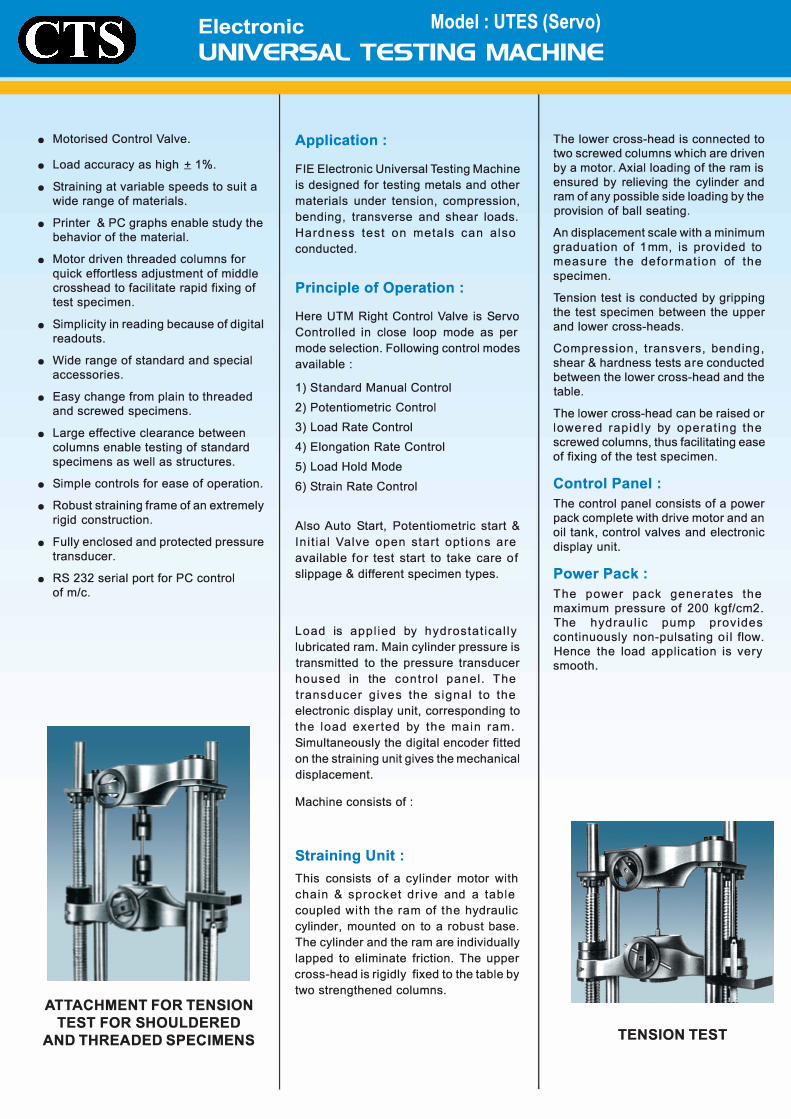
ATTACHMENT FOR TENSION
TEST FOR SHOULDERED
AND THREADED SPECIMENS
Application:
FIE Electronic Universal Testing Machine
is designed for testing metals and other
materials under tension, compression,
bending, transverse and shear loads.
Hardness test on metals can also
conducted.
Principle of Operation :
Here UTM Right Control Valve is Servo
Controlled in close loop mode as per
mode selection. Following control modes
available:
1) Standard Manual Control
2) Potentiometric Control
3) Load Rate Control
4) Elongation Rate Control
5) Load Hold Mode
6) Strain Rate Control
Also Auto Start, Potentiometric start &
Initial Valve open start options are
available for test start to take care of
slippage & different specimen types.
Load is applied by hydrostatically
lubricated ram. Main cylinder pressure is
transmitted to the pressure transducer
housed in the control panel. The
transducer gives the signal to the
electronic display unit, corresponding to
the load exerted by the main ram.
Simultaneously the digital encoder fitted
on the straining unit gives the mechanical
displacement.
Machine consists of :
Straining Unit :
This consists of a cylinder motor with
chain & sprocket drive and a table
coupled with the ram of the hydraulic
cylinder, mounted on to a robust base.
The cylinder and the ram are individually
lapped to eliminate friction. The upper
cross-head is rigidly fixed to the table by
two strengthened columns.
The lower cross-head is connected to two screwed columns which are driven
by a motor. Axial loading of the ram is
ensured by relieving the cylinder and
ram of any possible side loading by the
provision of ball seating.
An displacement scale with a minimum
graduation of 1 mm, is provided to
measure the deformation of the
specimen.
Tension test is conducted by gripping
the test specimen between the upper
and lower cross-heads.
Compression, transvers, bending,
shear & hardness tests are conducted
between the lower cross-head and the
table.
The lower cross-head can be raised or
lowered rapidly by operating the
screwed columns, thus facilitating ease
of fixing of the test specimen.
Control Panel :
The control panel consists of a power
pack complete with drive motor and an
oil tank, control valves and electronic
display unit.
Power Pack:
The power pack generates the
maximum pressure of 200 kgf/cm2.
The hydraulic pump provides
continuously non-pulsating oil flow.
Hence the load application is very
smooth.
TENSION TEST
Electronic Model : LITES (Servo) UNIVERSAL TESTING MACHINE
Hydraulic Controls :
Hand operated Release Valve & motorised
control valve are used to control the flow to
and from the hydraulic cylinder. T he
regulation of the oil flow is infinitely variable.
Incorporated in the hydraulic system is a
regulating valve, which maintains a
practically constant rate of piston
movement. Control by this valve allows
extensometer reading to be taken.
Electronic Control Panel (FIE-SERVO) :
• In electronic panel 8085 microprocessor
is used for basic UTM operation & an 8
bit dedicated microcontroller is used for
close loop & Servo Control.
• Panel is having parallel printer port,
RS 232 C serial port for PC interface.
• 2 lines x 8 digits 7 segment display &
membrane keyboard for data entry.
• 20 data sets and 50 results storage.
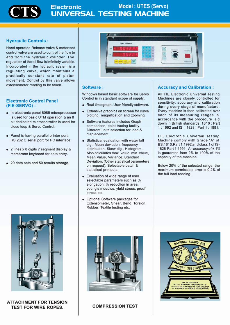
ATTACHMENT FOR TENSION TEST FOR WIRE ROPES.
�----- -� ---
•
� �
Software:
Windows based basic software for Servo Control is in standard scope of supply.
• Real time graph, User friendly software.
• Extensive graphics on screen for curveplotting, magnification and zooming.
• Software features includes Graphcomparison, point tracing facility.
Different units selection for load &displacement.
• Statistical evaluation with water fall
dig., Mean deviation, frequencydistribution, Skew dig., Histogram.Also calculates max. value, min. value,
Mean Value, Variance, StandardDeviation. (Other statistical parameterson request). Selectable batch &statistical printouts.
• Evaluation of wide range of userselectable parameters such as %elongation, % reduction in area,young's modulus, yield stress, proofstress etc.
• Optional Software packages forExtensometer, Shear, Bend, Torsion,Rubber, Textile testing etc.
COMPRESSION TEST
Accuracy and Calibration :
All FIE Electronic Universal Testing Machines are closely controlled for sensitivity, accuracy and calibration during every stage of manufacture. Every machine is then calibrated over each of its measuring ranges in
accordance with the procedure laid down in British standards. 1610 : Part 1 : 1992 and IS : 1828: Part 1: 1991.
FIE Electronic Universal Testing Machine comply with Grade "A" of BS:1610:Part 1 :1992 and class 1 of IS-1828-Part 1: 1991. An accuracy of± 1 % is guaranted from 2% to 100% of the
capacity of the machine.
Below 20% of the selected range, the maximum permissible error is 0.2% of the full load reading.

C Maximum Capacity kN 100 200 400 600 1000
0 Measuring Range kN 0-100 0-200 0-400 0-600 0-1000
·- Load Resolution ( 20,000 counts full scale) N 5 10 20 30 50
ns Load Range with Accuracy of
(.) measurement± 1.0% kN 2to 100 4to 200 8to 400 12to 600 20to 1000 Resolution of piston movement
·- (Displacement) mm 0.01 0.01 0.01 0.01 0.01 ·- Clearance for tensile at (.) fully descended working piston . mm 50-700 50-700 50-700 50-800 50-850
Cl) Clearance for compression test at fully descended working piston . mm 0-700 0-700 0-700 0-800 0-850
C. Clearance between columns . mm 500 500 500 600 750Ram Stroke mm 150 200 200 250 250Straining/piston speed (at no load) mm/min 0-300 0-150 0-150 0-100 0-80CONNECTED LOAD
Power kW 1.0 1.0 1.7 1.9 2.6 Voltage V ac 400-440 400-440 400-440 400-440 400-440Phase (.0) 3 3 3 3 3DIMENSIONSLxWxH (approx .) mm 2032x 2032x 2060x 2265x 2415x
750x 750x 750x 750x 815x 1960x 1960x 2180x 2534x 2900x
WEIGHT (approx .) kg . 1500 1500 2500 3500 5500 STANDARD ACCESSORIES
FOR TENSION TEST
• Clam ping jaws for round mm 10-20 10-20 10-25 10-25 10-25specimens of Diameters . 25-40 25-45
20-30 20-30 25-40 40-55 45-70
• Clam ping jaws for flat mm 0-10 0-10 0-15 0-15 0-22specimens of thickness . 10-20 10-20 15-30 15-30 22-44
44-65Width mm 50 50 65 70 70FOR COMPRESSION TEST Pair of compression plates of dia . mm 120 120 120 120 160
FOR TRANSVERSE TEST Table with adjustable rollers width of rollers. mm 160 160 160 160 160 Diameter of Rollers mm 30 30 30 50 50 Maximum clearance between supports mm 500 500 500 600 800 Radius of punch tops. mm 6,12 6,12 12, 16 16,22 16,22
SPECIAL ACCESSORIES & OPTIONS
• Electronic extensometer • Shear test attachment• Brinell test attachment • Software packages
Printer
• Wide range accessories offered on request at additional cost . • Due to constant R & D specifications & features aresubject to change without notice. • The dimensions given above are approximate.
* PC & Printer is not in our standard scope of supply.