Embed Size (px)
Citation preview

Available online at www.sciencedirect.com
ScienceDirectPublishing Services by Elsevier
International Journal of Naval Architecture and Ocean Engineering 8 (2016) 442e455http://www.journals.elsevier.com/international-journal-of-naval-architecture-and-ocean-engineering/
Model tests on resistance and seakeeping performance of wave-piercinghigh-speed vessel with spray rails
Jeonghwa Seo a, Hak-Kyu Choi a, Uh-Cheul Jeong b, Dong Kun Lee c, Shin Hyung Rhee a,d,Chul-Min Jung e, Jaehoon Yoo f,*
a Dept. of Naval Architecture and Ocean Engineering, Seoul National University, Seoul, South Koreab Dept. of Naval Architecture and Ocean Engineering, Inha Technical College, Incheon, South Korea
c Dept. of Naval Architecture and Ocean Engineering, Mokpo National Maritime University, Mokpo, South Koread Research Institute of Marine Systems Engineering, Seoul National University, Seoul, South Koreae The 6th R&D Institute-3rd Directorate, Agency for Defense Development, Changwon, South Korea
f Dept. of Ocean Engineering, Mokpo National University, Muan, South Korea
Received 3 February 2016; revised 18 May 2016; accepted 22 May 2016
Available online 16 July 2016
Abstract
The resistance and seakeeping performance of a high-speed monohull vessel were investigated through a series of model tests in a towingtank. The hull had a slender wave-piercing bow, round bilge, and small deadrise angle on stern. Tests on the bare hull in calm water werefirst conducted and tests on spray rails followed. The spray rails were designed to control the flow direction and induce a hydrodynamic liftforce on the hull bottom to reduce trim angle and increase rise of the hull. The maximum trim of the bare hull was 4.65� at the designedspeed, but the spray rails at optimum location reduced trim by 0.97�. The ship motion in head seas was examined after the calm water tests.Attaching the rails on the optimum location effectively reduced the pitch and heave motion responses. The vertical acceleration at the foreperpendicular reduced by 11.3%. The effective power in full scale was extrapolated from the model test results and it was revealed that thespray rails did not have any negative effects on the resistance performance of the hull, while they effectively stabilized the vessel in calmwater and waves.Copyright © 2016 Society of Naval Architects of Korea. Production and hosting by Elsevier B.V. This is an open access article under theCC BY-NC-ND license (http://creativecommons.org/licenses/by-nc-nd/4.0/).
Keywords: Wave-piercing bow; High-speed vessel; Model test; Seakeeping
1. Introduction
High-speed vessels are designed to reach a relatively highspeed with limited motor power. Therefore, various hull de-signs and appendages have been applied to reduce the wave-making resistance and the wetted surface area. Among them,the planing hull is one of the most widely used. This planinghull is designed to reduce the drag force by raising the hull,
* Corresponding author.
E-mail address: [email protected] (J. Yoo).
Peer review under responsibility of Society of Naval Architects of Korea.
http://dx.doi.org/10.1016/j.ijnaoe.2016.05.010
2092-6782/Copyright© 2016 Society of Naval Architects of Korea. Production and
license (http://creativecommons.org/licenses/by-nc-nd/4.0/).
utilizing the hydrodynamic pressure at the bottom of the ship.As the hull is not equipped with prominent appendages suchas hydrofoils, the hull shape is relatively simple; design,manufacturing, and maintenance of the planing hull areeasier than those of other types of high speed vessels. Theplaning hull employs a wide bottom area to obtain sufficientlift force to raise the hull; thus, strong resonances in pitch andheave motions develop periodically in response to wavesbecause of the wide bottom. Because strong vertical reso-nance motion and the slamming impact can damage the hulland harm passengers, it is important in the design stage of theplaning hull to analyze and minimize the impact of the hull inwaves.
hosting by Elsevier B.V. This is an open access article under the CC BY-NC-ND
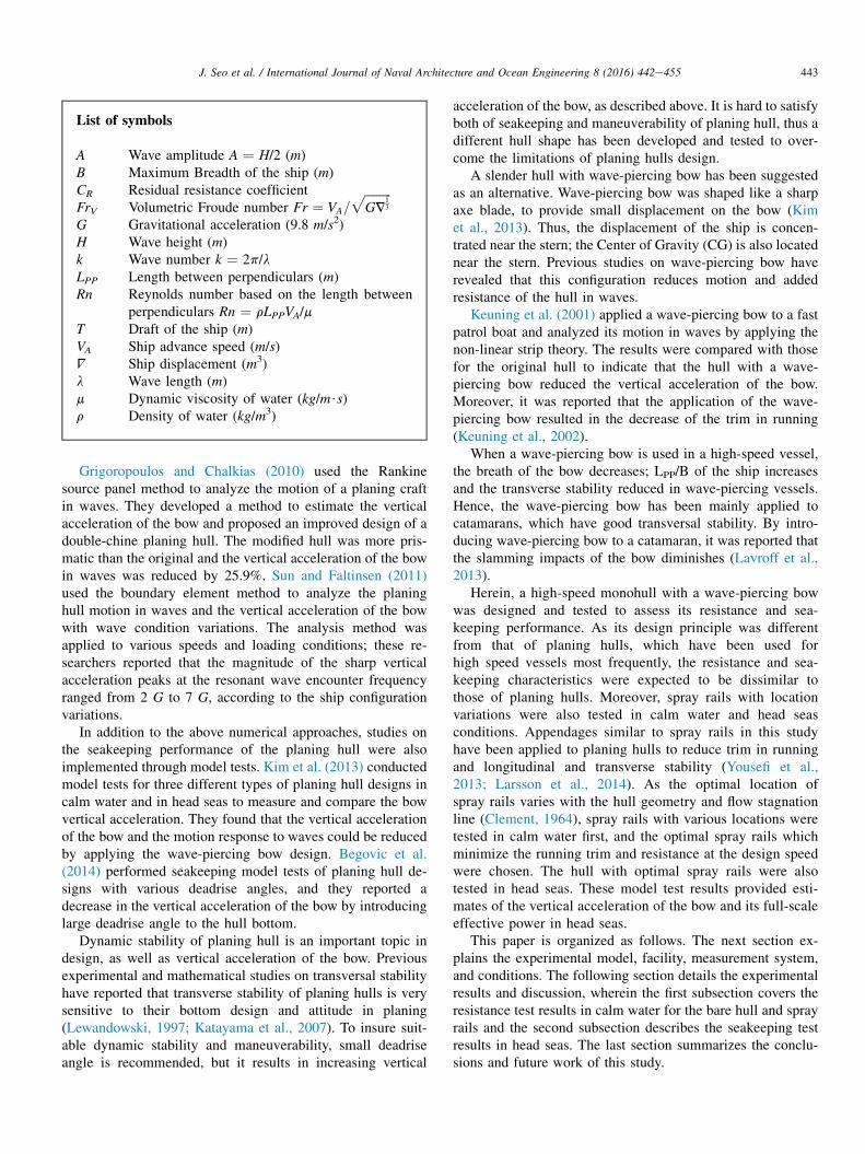
List of symbols
A Wave amplitude A ¼ H/2 (m)B Maximum Breadth of the ship (m)CR Residual resistance coefficientFrV Volumetric Froude number Fr ¼ VA=
ffiffiffiffiffiffiffiffiffiGV
13
p
G Gravitational acceleration (9.8 m/s2)H Wave height (m)k Wave number k ¼ 2p/lLPP Length between perpendiculars (m)Rn Reynolds number based on the length between
perpendiculars Rn ¼ rLPPVA/mT Draft of the ship (m)VA Ship advance speed (m/s)V Ship displacement (m3)l Wave length (m)m Dynamic viscosity of water (kg/m$s)r Density of water (kg/m3)
443J. Seo et al. / International Journal of Naval Architecture and Ocean Engineering 8 (2016) 442e455
Grigoropoulos and Chalkias (2010) used the Rankinesource panel method to analyze the motion of a planing craftin waves. They developed a method to estimate the verticalacceleration of the bow and proposed an improved design of adouble-chine planing hull. The modified hull was more pris-matic than the original and the vertical acceleration of the bowin waves was reduced by 25.9%. Sun and Faltinsen (2011)used the boundary element method to analyze the planinghull motion in waves and the vertical acceleration of the bowwith wave condition variations. The analysis method wasapplied to various speeds and loading conditions; these re-searchers reported that the magnitude of the sharp verticalacceleration peaks at the resonant wave encounter frequencyranged from 2 G to 7 G, according to the ship configurationvariations.
In addition to the above numerical approaches, studies onthe seakeeping performance of the planing hull were alsoimplemented through model tests. Kim et al. (2013) conductedmodel tests for three different types of planing hull designs incalm water and in head seas to measure and compare the bowvertical acceleration. They found that the vertical accelerationof the bow and the motion response to waves could be reducedby applying the wave-piercing bow design. Begovic et al.(2014) performed seakeeping model tests of planing hull de-signs with various deadrise angles, and they reported adecrease in the vertical acceleration of the bow by introducinglarge deadrise angle to the hull bottom.
Dynamic stability of planing hull is an important topic indesign, as well as vertical acceleration of the bow. Previousexperimental and mathematical studies on transversal stabilityhave reported that transverse stability of planing hulls is verysensitive to their bottom design and attitude in planing(Lewandowski, 1997; Katayama et al., 2007). To insure suit-able dynamic stability and maneuverability, small deadriseangle is recommended, but it results in increasing vertical
acceleration of the bow, as described above. It is hard to satisfyboth of seakeeping and maneuverability of planing hull, thus adifferent hull shape has been developed and tested to over-come the limitations of planing hulls design.
A slender hull with wave-piercing bow has been suggestedas an alternative. Wave-piercing bow was shaped like a sharpaxe blade, to provide small displacement on the bow (Kimet al., 2013). Thus, the displacement of the ship is concen-trated near the stern; the Center of Gravity (CG) is also locatednear the stern. Previous studies on wave-piercing bow haverevealed that this configuration reduces motion and addedresistance of the hull in waves.
Keuning et al. (2001) applied a wave-piercing bow to a fastpatrol boat and analyzed its motion in waves by applying thenon-linear strip theory. The results were compared with thosefor the original hull to indicate that the hull with a wave-piercing bow reduced the vertical acceleration of the bow.Moreover, it was reported that the application of the wave-piercing bow resulted in the decrease of the trim in running(Keuning et al., 2002).
When a wave-piercing bow is used in a high-speed vessel,the breath of the bow decreases; LPP/B of the ship increasesand the transverse stability reduced in wave-piercing vessels.Hence, the wave-piercing bow has been mainly applied tocatamarans, which have good transversal stability. By intro-ducing wave-piercing bow to a catamaran, it was reported thatthe slamming impacts of the bow diminishes (Lavroff et al.,2013).
Herein, a high-speed monohull with a wave-piercing bowwas designed and tested to assess its resistance and sea-keeping performance. As its design principle was differentfrom that of planing hulls, which have been used forhigh speed vessels most frequently, the resistance and sea-keeping characteristics were expected to be dissimilar tothose of planing hulls. Moreover, spray rails with locationvariations were also tested in calm water and head seasconditions. Appendages similar to spray rails in this studyhave been applied to planing hulls to reduce trim in runningand longitudinal and transverse stability (Yousefi et al.,2013; Larsson et al., 2014). As the optimal location ofspray rails varies with the hull geometry and flow stagnationline (Clement, 1964), spray rails with various locations weretested in calm water first, and the optimal spray rails whichminimize the running trim and resistance at the design speedwere chosen. The hull with optimal spray rails were alsotested in head seas. These model test results provided esti-mates of the vertical acceleration of the bow and its full-scaleeffective power in head seas.
This paper is organized as follows. The next section ex-plains the experimental model, facility, measurement system,and conditions. The following section details the experimentalresults and discussion, wherein the first subsection covers theresistance test results in calm water for the bare hull and sprayrails and the second subsection describes the seakeeping testresults in head seas. The last section summarizes the conclu-sions and future work of this study.

444 J. Seo et al. / International Journal of Naval Architecture and Ocean Engineering 8 (2016) 442e455
2. Experimental methods and conditions
2.1. Testing facility and measurement systems
The model tests were conducted in the Seoul NationalUniversity Towing Tank (SNUTT). The length, width, anddepth of the towing tank were 110 m, 8 m, and 3.5 m,respectively. In the towing tank, a truss-type high-speed car-riage was installed to tow the test model. Fig. 1 presents aschematic diagram of the towing system. It was installed onthe high-speed towing carriage and allowed test model mo-tions with two degrees of freedom, in pitch and heave. Thespecific design and mechanisms of the gimbal were detailed inthe experimental study by Kim (2012). The gimbal wasdesigned to transmit the external towing force from the towingcarriage to the test model in the longitudinal direction of thehull, regardless of the running trim. The pivot of the gimbal,i.e., the center of pitch motion, was located at the intersectionof the propulsor axis and the vertical CG of the model ship.
The heave and pitch motions of the model were indepen-dently measured by two potentiometers. A load cell with full-bridge strain gauges was used to measure the resistance forceof the model. The maximum measurable force in the longi-tudinal direction was 200 N. The resistance force and the pitchand heave motions were measured using a data acquisitionsystem (MX840A, Hottinger Baldwin Messetechnik GmbH,Darmstadt, Germany) with a sampling frequency of 100 Hz.
The test system constrained roll and yaw motion to focuson pitch and heave motion, which are primarily induced inhead seas. As mentioned in the introduction, wave-piercinghulls have less static transversal stability than planing hulls,due to slender hull geometry. In the case of dynamic stability,on the other hand, attitude changes in running wave-piercinghulls are similar to those in semi-displacement type hullsand smaller than those in planing hull, thus changes in dy-namic stability of wave-piercing hull is expected to be small.The transverse stability can be examined by towing tests withfree-roll (Katayama et al., 2007), but the experimental setupwas not applied in this study, thus measuring roll motion ormoment in towing is remained as future work.
The measurement system's test uncertainty was assessedfollowing the standard of the American Society of Mechan-ical Engineers (ASME, 2005). Table 1 shows uncertainty
Fig. 1. Schematic diagram of the towing mechanisms.
assessment results. The total uncertainties with 95% confi-dence level of the pitch angle, heave displacement, andresistance were 0.0630�, 1.14 mm, and 0.572 N, respectively.Dynamic range means maximum of measured value in calmwater towing test.
2.2. Test model
The test model was a monohull with a wave-piercing bow.Fig. 2 shows the geometry of the model ship. While previousstudies on wave-piercing hull have focused on the installationof wave-piercing bow to existing high speed hulls to examinebow modification effects (Keuning et al., 2002; Kim et al.,2013), the newly-designed wave-piercing monohull haddifferent hull geometry from traditional planing hull. Thedesign principle of wave-piercing hull was maintaining smalltrim angle to immerse the bow edge in waves, rather thangenerate lift force on the hull bottom; thus, hard chine wasexcluded in the hull design initially.
The wave-piercing bow was designed to reduce verticalmotion in head seas, by reducing the volume of the bow; thebow was deep-V shaped and very slender, thus displacementwas concentrated near the stern with small deadrise angle.The deadrise angle of the test model was 15� at aft perpen-dicular (AP). It is reported that small deadrise angle increasesvertical acceleration of the bow in waves, but the wave-piercing bow could reduce the bow acceleration effectively.After the tests of bare hull with round bilge, spray rails withinstallation location variation were applied, to confirmresistance performance improvements and provide transversestability.
Like other high speed vessels, trim tabs or interceptors wereable to be applied to the hull; but spray rails which couldpassively provide additional roll stability were considered firstin the study, as the wave-piercing monohull has inferiortransverse stability because of large LPP/B. Moreover, trim inrunning was small enough as designed, thus appendages forreducing trim, i.e., interceptors or trim tabs, were not neces-sary. Future study will concern effects of spray rails ontransverse stability.
LPP and displacement of the ship in full scale were 30 mand 59.8 m3, respectively. The maximum design speed ofthe vessel in full scale was 50 knots. The scale ratio of thetest model was 1/15 and the LPP of the test model was 2 m.Principal particulars of the hull are presented in Table 2.As the bow was slender and had a small displacement,the CG of the ship was located at 32.8% of LPP, forwardfrom AP.
The bare hull with round bilge was tested first, and sprayrails were attached on the hull to reduce trim in running. Theywere designed to change the flow direction on the hull bottomand provide additional lift force on the stern. The rails wereplaced from the longitudinal CG of the hull to AP. They wereparallel to the longitudinal centerline of the hull. They werepositioned at various vertical locations to find the optimallocation, where the trim in running was minimized. Fig. 3shows the location and geometry of spray rails. The fore

Table 1
Test uncertainty.
Item Unit Systematic error Random error Total uncertainty
(95% confidence level)
Dynamic range Total uncertainty/Dynamic range (%)
Towing speed m/s 0.0314 0.0025 0.0630 7.969 0.791
Trim angle � 0.05 0.042 0.131 4.65 2.81
Rise of C.G. mm 0.25 0.513 1.14 53.8 2.12
Resistance N 0.032 0.284 0.572 40.47 1.41
Wave period s 0.005 0.000100 0.0100 2.53 0.395
Wave height mm 0.05 0.178 0.370 66.6 0.555
Fig. 2. The wave-piercing monohull: the geometry of the hull (top) and lines of the hull (bottom).
Table 2
Principal particulars of the wave piercing monohull.
Item Unit Full scale Test model
Scale ratio 1 1/15
LPP m 30 2.0
B m 5.12 0.341
T m 0.93 0.062
Water plane area m2 95.9 0.426
Wetted surface area m2 119.0 0.528
V m3 59.8 0.0177
Longitudinal center of buoyancy
(from the aft perpendicular)
m 9.87 0.658
Vertical center of buoyancy
(from the baseline)
m 0.576 0.0384
Vertical center of gravity
(from the baseline)
m 1.61 0.107
GM m 1.53 0.102
Radius of gyration
(transversal direction)
m 7.5 0.50
Block coefficient 0.408
445J. Seo et al. / International Journal of Naval Architecture and Ocean Engineering 8 (2016) 442e455
part of the rails was tapered to make the surface smooth. In themodel tests, the distance from the bottom of the rails to thecalm water surface were chosen at 8%, 24%, and 40% of T. Itswidth was 22.5% of T.
2.3. Test conditions
Model tests were first conducted in calm water conditions(Table 3). Frv herein ranged from 0.416 to 4.158. Corre-sponding ship speed in the full scale ranged from 5 to 50 knots.During towing, trim, rise of CG, and resistance weremeasured. Bare hull and three spray rail cases were tested.
In head seas condition, bare hull and a spray rail (24% T )case were tested. Table 4 shows the wave conditions for thetests in head seas. l/LPP ranged from 1.0 to 5.0. Test model inhead seas was towed in constant speed, which implies thrustvariation in the full scale trial. The model tests of the bare hull
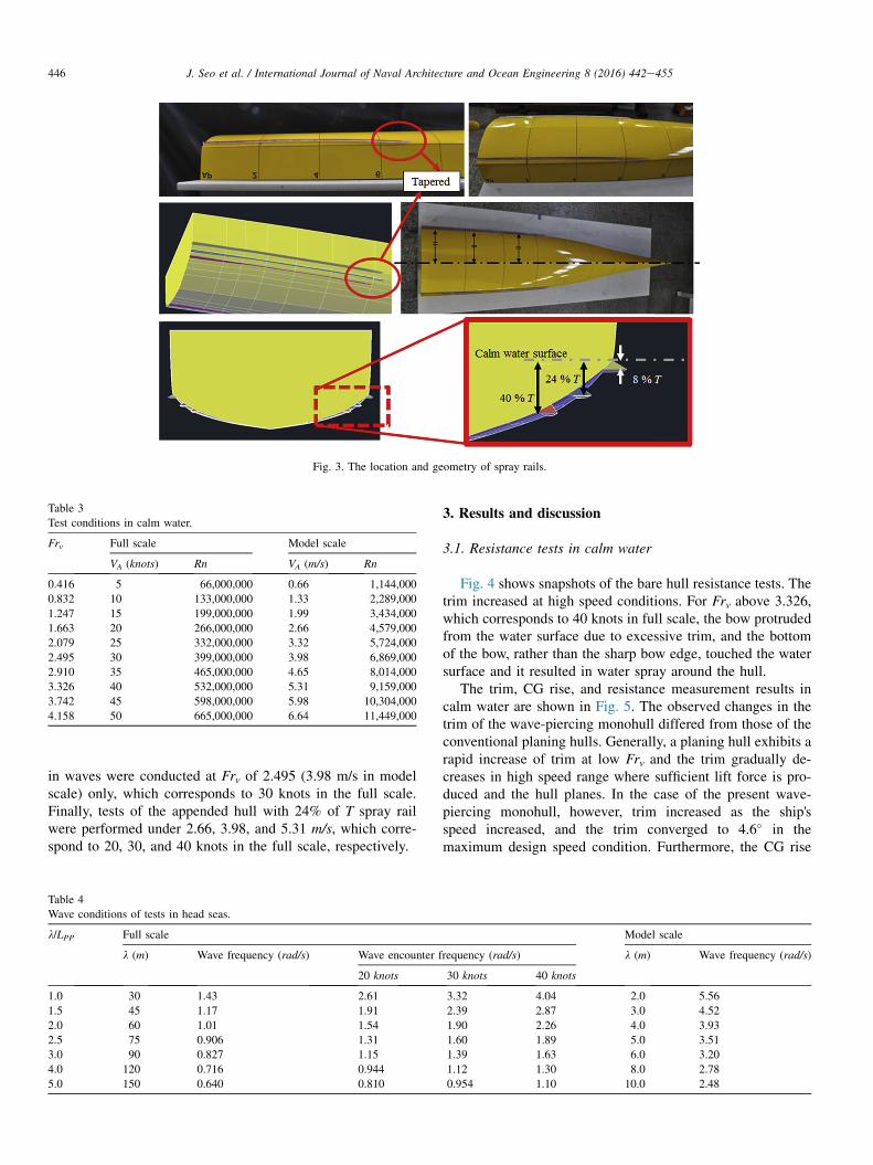
Fig. 3. The location and geometry of spray rails.
Table 3
Test conditions in calm water.
Frv Full scale Model scale
VA (knots) Rn VA (m/s) Rn
0.416 5 66,000,000 0.66 1,144,000
0.832 10 133,000,000 1.33 2,289,000
1.247 15 199,000,000 1.99 3,434,000
1.663 20 266,000,000 2.66 4,579,000
2.079 25 332,000,000 3.32 5,724,000
2.495 30 399,000,000 3.98 6,869,000
2.910 35 465,000,000 4.65 8,014,000
3.326 40 532,000,000 5.31 9,159,000
3.742 45 598,000,000 5.98 10,304,000
4.158 50 665,000,000 6.64 11,449,000
446 J. Seo et al. / International Journal of Naval Architecture and Ocean Engineering 8 (2016) 442e455
in waves were conducted at Frv of 2.495 (3.98 m/s in modelscale) only, which corresponds to 30 knots in the full scale.Finally, tests of the appended hull with 24% of T spray railwere performed under 2.66, 3.98, and 5.31 m/s, which corre-spond to 20, 30, and 40 knots in the full scale, respectively.
Table 4
Wave conditions of tests in head seas.
l/LPP Full scale
l (m) Wave frequency (rad/s) Wave encounter f
20 knots
1.0 30 1.43 2.61
1.5 45 1.17 1.91
2.0 60 1.01 1.54
2.5 75 0.906 1.31
3.0 90 0.827 1.15
4.0 120 0.716 0.944
5.0 150 0.640 0.810
3. Results and discussion
3.1. Resistance tests in calm water
Fig. 4 shows snapshots of the bare hull resistance tests. Thetrim increased at high speed conditions. For Frv above 3.326,which corresponds to 40 knots in full scale, the bow protrudedfrom the water surface due to excessive trim, and the bottomof the bow, rather than the sharp bow edge, touched the watersurface and it resulted in water spray around the hull.
The trim, CG rise, and resistance measurement results incalm water are shown in Fig. 5. The observed changes in thetrim of the wave-piercing monohull differed from those of theconventional planing hulls. Generally, a planing hull exhibits arapid increase of trim at low Frv and the trim gradually de-creases in high speed range where sufficient lift force is pro-duced and the hull planes. In the case of the present wave-piercing monohull, however, trim increased as the ship'sspeed increased, and the trim converged to 4.6� in themaximum design speed condition. Furthermore, the CG rise
Model scale
requency (rad/s) l (m) Wave frequency (rad/s)
30 knots 40 knots
3.32 4.04 2.0 5.56
2.39 2.87 3.0 4.52
1.90 2.26 4.0 3.93
1.60 1.89 5.0 3.51
1.39 1.63 6.0 3.20
1.12 1.30 8.0 2.78
0.954 1.10 10.0 2.48
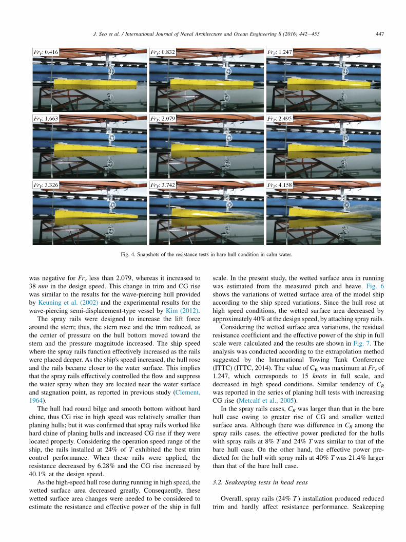
Fig. 4. Snapshots of the resistance tests in bare hull condition in calm water.
447J. Seo et al. / International Journal of Naval Architecture and Ocean Engineering 8 (2016) 442e455
was negative for Frv less than 2.079, whereas it increased to38 mm in the design speed. This change in trim and CG risewas similar to the results for the wave-piercing hull providedby Keuning et al. (2002) and the experimental results for thewave-piercing semi-displacement-type vessel by Kim (2012).
The spray rails were designed to increase the lift forcearound the stern; thus, the stern rose and the trim reduced, asthe center of pressure on the hull bottom moved toward thestern and the pressure magnitude increased. The ship speedwhere the spray rails function effectively increased as the railswere placed deeper. As the ship's speed increased, the hull roseand the rails became closer to the water surface. This impliesthat the spray rails effectively controlled the flow and suppressthe water spray when they are located near the water surfaceand stagnation point, as reported in previous study (Clement,1964).
The hull had round bilge and smooth bottom without hardchine, thus CG rise in high speed was relatively smaller thanplaning hulls; but it was confirmed that spray rails worked likehard chine of planing hulls and increased CG rise if they werelocated properly. Considering the operation speed range of theship, the rails installed at 24% of T exhibited the best trimcontrol performance. When these rails were applied, theresistance decreased by 6.28% and the CG rise increased by40.1% at the design speed.
As the high-speed hull rose during running in high speed, thewetted surface area decreased greatly. Consequently, thesewetted surface area changes were needed to be considered toestimate the resistance and effective power of the ship in full
scale. In the present study, the wetted surface area in runningwas estimated from the measured pitch and heave. Fig. 6shows the variations of wetted surface area of the model shipaccording to the ship speed variations. Since the hull rose athigh speed conditions, the wetted surface area decreased byapproximately 40% at the design speed, by attaching spray rails.
Considering the wetted surface area variations, the residualresistance coefficient and the effective power of the ship in fullscale were calculated and the results are shown in Fig. 7. Theanalysis was conducted according to the extrapolation methodsuggested by the International Towing Tank Conference(ITTC) (ITTC, 2014). The value of CR was maximum at Frv of1.247, which corresponds to 15 knots in full scale, anddecreased in high speed conditions. Similar tendency of CR
was reported in the series of planing hull tests with increasingCG rise (Metcalf et al., 2005).
In the spray rails cases, CR was larger than that in the barehull case owing to greater rise of CG and smaller wettedsurface area. Although there was difference in CR among thespray rails cases, the effective power predicted for the hullswith spray rails at 8% T and 24% T was similar to that of thebare hull case. On the other hand, the effective power pre-dicted for the hull with spray rails at 40% T was 21.4% largerthan that of the bare hull case.
3.2. Seakeeping tests in head seas
Overall, spray rails (24% T ) installation produced reducedtrim and hardly affect resistance performance. Seakeeping
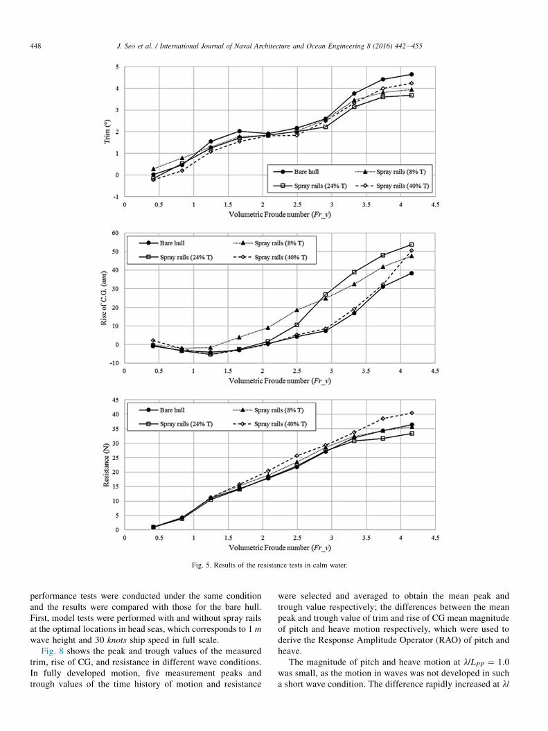
Fig. 5. Results of the resistance tests in calm water.
448 J. Seo et al. / International Journal of Naval Architecture and Ocean Engineering 8 (2016) 442e455
performance tests were conducted under the same conditionand the results were compared with those for the bare hull.First, model tests were performed with and without spray railsat the optimal locations in head seas, which corresponds to 1 mwave height and 30 knots ship speed in full scale.
Fig. 8 shows the peak and trough values of the measuredtrim, rise of CG, and resistance in different wave conditions.In fully developed motion, five measurement peaks andtrough values of the time history of motion and resistance
were selected and averaged to obtain the mean peak andtrough value respectively; the differences between the meanpeak and trough value of trim and rise of CG mean magnitudeof pitch and heave motion respectively, which were used toderive the Response Amplitude Operator (RAO) of pitch andheave.
The magnitude of pitch and heave motion at l/LPP ¼ 1.0was small, as the motion in waves was not developed in sucha short wave condition. The difference rapidly increased at l/
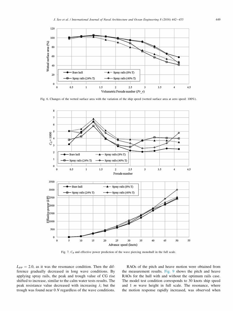
Fig. 6. Changes of the wetted surface area with the variation of the ship speed (wetted surface area at zero speed: 100%).
Fig. 7. CR and effective power prediction of the wave piercing monohull in the full scale.
449J. Seo et al. / International Journal of Naval Architecture and Ocean Engineering 8 (2016) 442e455
LPP ¼ 2.0, as it was the resonance condition. Then the dif-ference gradually decreased in long wave conditions. Byapplying spray rails, the peak and trough value of CG riseshifted to increase, similar to the calm water tests results. Thepeak resistance value decreased with increasing l; but thetrough was found near 0 N regardless of the wave conditions.
RAOs of the pitch and heave motion were obtained fromthe measurement results. Fig. 9 shows the pitch and heaveRAOs for the hull with and without the optimum rails case.The model test condition corresponds to 30 knots ship speedand 1 m wave height in full scale. The resonance, wherethe motion response rapidly increased, was observed when

Fig. 8. Model test results in head seas (wave height 1 m, 30 knots).
450 J. Seo et al. / International Journal of Naval Architecture and Ocean Engineering 8 (2016) 442e455
l/LPP ¼ 2.5 for the pitch motion and l/LPP ¼ 2.0 for the heavemotion. When rails were attached on the hull, the pitch andheave RAO decreased under all wave length conditions. Thepitch and heave RAO under resonance conditions decreased by10.5% and 18.4%, respectively.
In Kim et al.’s study (2013), the pitch and heave motionswere measured through model tests of a high-speed vessel andthey were composed to obtain vertical displacement of theFore Perpendicular (FP), considering the hull as a rigid body
with pitch and heave motion only. By second derivative of thevertical displacement, vertical acceleration of FP could bederived; however, the calculated vertical acceleration did notreflect the impact on the bow meeting the water surface thatcould be acquired from the direct measurement results by anaccelerometer. Nevertheless, it could be used for qualitativeassessment of the vertical acceleration of FP.
Fig. 10 shows the time-history of the heave and pitchmeasurement results and derived FP vertical displacement for
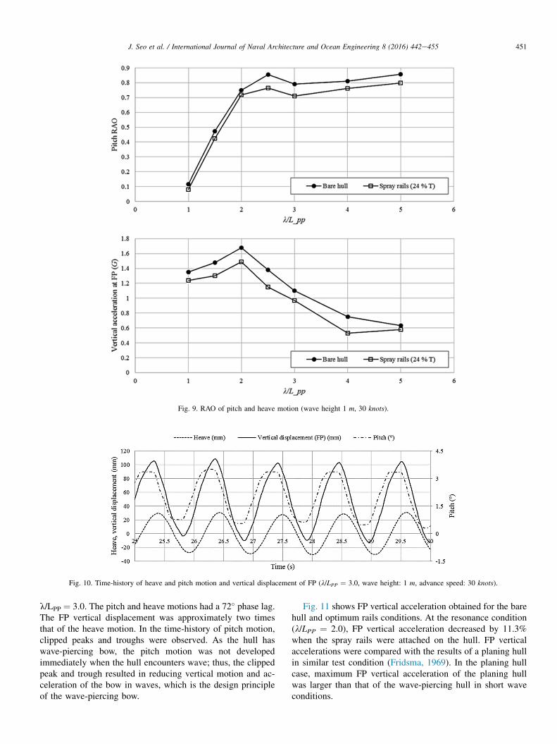
Fig. 9. RAO of pitch and heave motion (wave height 1 m, 30 knots).
Fig. 10. Time-history of heave and pitch motion and vertical displacement of FP (l/LPP ¼ 3.0, wave height: 1 m, advance speed: 30 knots).
451J. Seo et al. / International Journal of Naval Architecture and Ocean Engineering 8 (2016) 442e455
l/LPP ¼ 3.0. The pitch and heave motions had a 72� phase lag.The FP vertical displacement was approximately two timesthat of the heave motion. In the time-history of pitch motion,clipped peaks and troughs were observed. As the hull haswave-piercing bow, the pitch motion was not developedimmediately when the hull encounters wave; thus, the clippedpeak and trough resulted in reducing vertical motion and ac-celeration of the bow in waves, which is the design principleof the wave-piercing bow.
Fig. 11 shows FP vertical acceleration obtained for the barehull and optimum rails conditions. At the resonance condition(l/LPP ¼ 2.0), FP vertical acceleration decreased by 11.3%when the spray rails were attached on the hull. FP verticalaccelerations were compared with the results of a planing hullin similar test condition (Fridsma, 1969). In the planing hullcase, maximum FP vertical acceleration of the planing hullwas larger than that of the wave-piercing hull in short waveconditions.
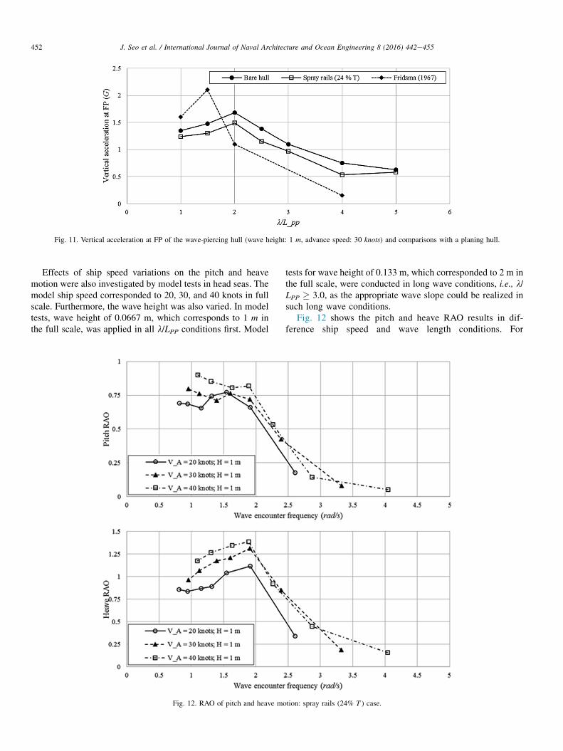
Fig. 11. Vertical acceleration at FP of the wave-piercing hull (wave height: 1 m, advance speed: 30 knots) and comparisons with a planing hull.
452 J. Seo et al. / International Journal of Naval Architecture and Ocean Engineering 8 (2016) 442e455
Effects of ship speed variations on the pitch and heavemotion were also investigated by model tests in head seas. Themodel ship speed corresponded to 20, 30, and 40 knots in fullscale. Furthermore, the wave height was also varied. In modeltests, wave height of 0.0667 m, which corresponds to 1 m inthe full scale, was applied in all l/LPP conditions first. Model
Fig. 12. RAO of pitch and heave mo
tests for wave height of 0.133 m, which corresponded to 2 m inthe full scale, were conducted in long wave conditions, i.e., l/LPP � 3.0, as the appropriate wave slope could be realized insuch long wave conditions.
Fig. 12 shows the pitch and heave RAO results in dif-ference ship speed and wave length conditions. For
tion: spray rails (24% T ) case.

453J. Seo et al. / International Journal of Naval Architecture and Ocean Engineering 8 (2016) 442e455
comparisons of the test results in different ship speeds, thewave-encounter frequency in the full scale was used, ratherthan the wave length ratio. For the heave RAO, the reso-nance region can be clearly observed near the wave-encounter frequency of 2 rad/s. In high wave-encounterfrequency conditions, i.e., short waves, the motion was notfully developed and RAO was small. In contrast, the RAOconverged to 1 in the low frequency domain, as the testmodel followed the wave motion. The pitch RAO was smallin high wave-encounter frequencies, similar to the heaveRAO, but there was difference in the resonance frequency. Inmodel speeds corresponding to 20 and 30 knots in full scale,resonance occurred around the wave-encounter frequency infull scale of 1.5 rad/s, whereas resonance occurred at1.8 rad/s in 40 knots condition. It seems to be caused by thetrim change in high speed. In high speed, as shown in theresistance test results, hull bottom was exposed and sea-keeping performance might change.
Fig. 13. Snapshots of the model tests in hea
Fig. 13 shows snapshots of the model test conducted at l/LPP ¼ 2.0. The bow was exposed above the water surfaceperiodically, but the impact of slamming was expected to besmaller than that of conventional planing hull, as the bow ofthe test model has large deadrise angle and small bottom area.
Fig. 14 presents the comparison of estimated FP verticalaccelerations with respect to the wave-encounter frequency.The largest vertical acceleration was found for the 40 knotscondition, where the bow was frequently exposed above thewater surface. For the 20 and 30 knots in full scale condi-tions, similar FP vertical acceleration was obtained whereasvertical acceleration of FP increased proportionally with theship speed in the planing hull case (Fridsma, 1969).
The effective power in head seas was estimated using theaverage resistance obtained from the model tests and shown inFig. 15. The effective power increased in the short wave regionwith a large wave-encounter frequency. The effective poweralso increased in high wave height cases.
d seas (wave height: 1 m; l/LPP ¼ 2.0).

Fig. 14. Vertical acceleration at FP of the wave-piercing monohull with spray rails (24% T ).
Fig. 15. Effective power prediction of the wave piercing monohull with rails in head seas.
454 J. Seo et al. / International Journal of Naval Architecture and Ocean Engineering 8 (2016) 442e455
4. Conclusion and future work
The resistance and seakeeping performance of a newly-designed wave-piercing monohull were assessed through aseries of model tests. Installing the wave-piercing bow andthe spray rails reduced both the running trim and verticalacceleration of FP in waves. Resistance tests for the barehull were conducted first, followed by tests of different lo-cations of the rails in calm water. The trim of the bare hullin the design speed condition was 4.65�, and the railsat optimal location decreased the trim by approximately0.97�.
The seakeeping tests were performed for the bare hull andthe hull with the rails installed at the minimum running trim.It was revealed that the rails reduced pitch and heave motionsof the hull in head seas. Pitch and heave both decreased, thusthe FP vertical acceleration also diminished. Finally, theeffective power of the ship in the full scale was estimated.The wetted surface area changes due to the trim and rise ofCG variations in running were considered in the
extrapolation. The effective power increased in high wave-encounter frequency conditions.
In this study, the performed model tests focused on theresistance and seakeeping performance of the hull. As thehull has large LPP=B and low transverse stability, itsmaneuverability is expected to be significantly different withthat of conventional planing hull; research of the maneu-vering of such hulls is needed to be pursued in the futurestudy.
Acknowledgments
This research was supported by the IT R&D programof MOTIE/KEIT (Grant No. 100660329), the NationalResearch Foundation grant funded by the Korean government(Grant Nos. 2013R1A1A2012597, 2011-0020563, and 2009-0083510), and Advanced Naval Vessel Research Laboratoryfunded by the Ministry of Defense. The support on experi-ments from Geuk-sang Yoo and Changhee Kim of SeoulNational University is gratefully acknowledged.

455J. Seo et al. / International Journal of Naval Architecture and Ocean Engineering 8 (2016) 442e455
References
ASME, 2005. Test uncertainty, The American society of mechanical engineers
performance test code, No. 19.1-2005. American Society of Mechanical
Engineers, New York, NY.
Begovic, E., Bertorello, C., Pennino, S., 2014. Experimental seakeeping
assessment of a warped planing hull model series. Ocean. Eng. 83, 1e15.
Clement, E.P., 1964. Effects of Longitudinal Bottom Spray Strips on Planing
Boat Resistance. DTMB Report, No. 1818. David Taylor Model Basin,
Washington, DC.
Fridsma, G., 1969. A Systematic Study of the Rough-water Performance of
Planing Boats. Davidson Laboratory Report, No. 1275. Stevens Institute of
Technology, Hoboken, NJ.
Grigoropoulos, G.J., Chalkias, D.S., 2010. Hull-form optimization in calm and
rough water. Comput. aided Des. 42, 977e984.
Katayama, T., Fujimoto, M., Ikeda, Y., 2007. A study on transverse stability
loss of planing craft at super high forward speed. Int. Shipbuild. Prog. 54
(4), 365e377.
Keuning, A., Toxopeus, S., Pinkster, J., 2001. The effect of bowshape on the
seakeeping performance of a fast monohull. In: Proceedings of FAST
Conference, Southampton, 2001.
Keuning, A., Pinkster, J., van Walree, F., 2002. Further investigation into the
hydrodynamic performance of the AXE bow concept. In: Proceedings of
the 6th Symposium on High Speed Marine Vehicles, Castello di Baia, Italy,
2002.
Kim, D.J., 2012. A Study on the Running Attitude and Dynamic Stability of a
Semi-displacement Round Bilge Vessel at High Speed. Ph.D. thesis. Seoul
National University, Seoul, Korea.
Kim, D.J., Kim, S.Y., You, Y.J., Rhee, K.P., Kim, S.H., Kim, Y.G., 2013.
Design of high-speed planing hulls for the improvement of resistance
and seakeeping performance. Int. J. Nav. Archit. Ocean Eng. 5,
161e177.
Larsson, L., Eliasson, R.E., Orych, M., 2014. Principles of Yacht Design,
fourth ed. Adlard Coles Nautical, London.
Lavroff, J., Davis, M.R., Holloway, D.S., Thomas, G., 2013. Wave slam-
ming loads on wave-piercer catamarans operating at high-speed deter-
mined by hydro-elastic segmented model experiments. Mar. Struct. 33,
120e142.
Lewandowski, E.M., 1997. Transverse dynamic stability of planing craft. Mar.
Technol. 34 (2), 109e118.
Metcalf, B.J., Faul, L., Bumiller, E., Slutsky, J., 2005. Resistance Tests of
a Systematic Series of U.S. Coast Guard Planing Hulls. Report of
Naval Surface Warfare Center Carderock Division, No. NSWCCD-50-TR-
2005/063. Naval SurfaceWarfare Center CarderockDivision, Bethesda,MD.
Sun, H., Faltinsen, O.M., 2011. Dynamic motions of planing vessels in head
seas. J. Mar. Sci. Technol. 16, 168e180.
Yousefi, R., Shafaghat, R., Shakeri, M., 2013. Hydrodynamic analysis
techniques for high-speed planing hulls. Appl. Ocean Res. 42,
105e113.