Embed Size (px)
Citation preview

MODEL T23108CHAIN SAW SHARPENER
OWNER'S MANUAL
COPYRIGHT © OCTOBER, 2010 BY GRIZZLY INDUSTRIAL, INC. REVISED JANUARY, 2015 (TR)WARNING: NO PORTION OF THIS MANUAL MAY BE REPRODUCED IN ANY SHAPE
OR FORM WITHOUT THE WRITTEN APPROVAL OF GRIZZLY INDUSTRIAL, INC.FOR MODELS MANUFACTURED SINCE 7/10 #TS13269 PRINTED IN CHINA

This manual provides critical safety instructions on the proper setup, operation, maintenance, and service of this machine/tool. Save this document, refer to it often, and use it to instruct other operators.
Failure to read, understand and follow the instructions in this manual may result in fire or serious personal injury—including amputation, electrocution, or death.
The owner of this machine/tool is solely responsible for its safe use. This responsibility includes but is not limited to proper installation in a safe environment, personnel training and usage authorization, proper inspection and maintenance, manual availability and compre-hension, application of safety devices, cutting/sanding/grinding tool integrity, and the usage of personal protective equipment.
The manufacturer will not be held liable for injury or property damage from negligence, improper training, machine modifications or misuse.
Some dust created by power sanding, sawing, grinding, drilling, and other construction activities contains chemicals known to the State of California to cause cancer, birth defects or other reproductive harm. Some examples of these chemicals are:
• Lead from lead-based paints.• Crystalline silica from bricks, cement and other masonry products.• Arsenic and chromium from chemically-treated lumber.
Your risk from these exposures varies, depending on how often you do this type of work. To reduce your exposure to these chemicals: Work in a well ventilated area, and work with approved safety equip-ment, such as those dust masks that are specially designed to filter out microscopic particles.

Table of ContentsINTRODUCTION
Manual Accuracy ........................................................................................................................ 2Contact Info ................................................................................................................................ 2Machine Description ................................................................................................................... 2Identification ............................................................................................................................... 3
SECTION 1: SAFETYSafety Instructions for Machinery ............................................................................................... 4Additional Safety for Chain Saw Sharpeners ............................................................................. 6
SECTION 2: POWER SUPPLYAvailability............................................................................................................................. 7Full-Load Current Rating ...................................................................................................... 7Circuit Requirements ............................................................................................................ 7Grounding & Plug Requirements ......................................................................................... 8Extension Cords ................................................................................................................... 8
SECTION 3: SETUPNeeded for Setup ....................................................................................................................... 9Unpacking .................................................................................................................................. 9Inventory ................................................................................................................................... 10Site Considerations .................................................................................................................. 11Mounting ................................................................................................................................... 12Assembly .................................................................................................................................. 13Installing Grinding Wheel ......................................................................................................... 14Power Connection .................................................................................................................... 15Test Run ................................................................................................................................... 15
SECTION 4: OPERATIONSChain Saw Terminology ........................................................................................................... 16How the Chain Cuts ................................................................................................................. 19Grinding Wheel Selection ......................................................................................................... 20Wheel Inspection & Ring Test .................................................................................................. 21Top Plate Angle ........................................................................................................................ 22Top Plate Cutting Angle ........................................................................................................... 23Gullet Angle .............................................................................................................................. 24Sharpening Operation .............................................................................................................. 25Depth Gauge Setting ................................................................................................................ 28Clamp Plate Adjustment ........................................................................................................... 28
SECTION 5: MAINTENANCESchedule .................................................................................................................................. 29Cleaning ................................................................................................................................... 29Lubrication ................................................................................................................................ 29Dressing Wheels ...................................................................................................................... 29
SECTION 6: SERVICETroubleshooting ........................................................................................................................ 30
SECTION 7: WIRINGWiring Safety Instructions ........................................................................................................ 31T23108 Wiring Diagram ........................................................................................................... 32
SECTION 8: PARTS ....................................................................................................................... 33
WARRANTY AND RETURNS ........................................................................................................ 37

-2- Model T23108 (Mfg. Since 7/10)
INTRODUCTION
Machine Description
We stand behind our machines. If you have any questions or need help, use the information below to contact us. Before contacting, please get the serial number and manufacture date of your machine. This will help us help you faster.
Grizzly Technical Support1203 Lycoming Mall Circle
Muncy, PA 17756Phone: (570) 546-9663
Email: [email protected]
We want your feedback on this manual. What did you like about it? Where could it be improved? Please take a few minutes to give us feedback.
Grizzly Documentation ManagerP.O. Box 2069
Bellingham, WA 98227-2069Email: [email protected]
Contact Info
We are proud to provide a high-quality owner’s manual with your new machine!
We made every effort to be exact with the instruc-tions, specifications, drawings, and photographs contained inside. Sometimes we make mistakes, but our policy of continuous improvement also means that sometimes the machine you receive will be slightly different than what is shown in the manual.
If you find this to be the case, and the difference between the manual and machine leaves you confused about a procedure, check our website for an updated version. We post current manuals and manual updates for free on our website at www.grizzly.com.
Alternatively, you can call our Technical Support for help. Before calling, please write down the Manufacture Date and Serial Number stamped into the machine ID label (see below). This infor-mation helps us determine if updated documenta-tion is available for your machine.
Manufacture Date
Serial Number
Manual Accuracy
The Model T23108 Chain Saw Sharpener quickly and accurately sharpens the cutter links of hand-held chain saws.
Once the sharpener is properly set up for the chain specifications, the three critical angles of the cutter link are sharpened with one downward movement of the spinning grinding wheel. The next cutter link is quickly and precisely moved into the correct position for sharpening with the aid of the adjustable advancement guide. This proce-dure ensures that all cutter links of the chain are sharpened to the same specifications.

Model T23108 (Mfg. Since 7/10) -3-
Identification
To reduce the risk of serious injury when using this machine, read and understand this entire manual before beginning any operations.
Figure 1. Model T23108 identification.
Swing ArmAssembly
Motor
Swing ArmHandle
Wheel& Arbor Guards
ChainClamp Lever
Swing ArmLock Knob
ON/OFFSwitch
Chain HolderAssembly
Chain HolderLock Knob
Base
DepthLock Bolt
Depth Stop

-4- Model T23108 (Mfg. Since 7/10)
ELECTRICAL EQUIPMENT INJURY RISKS. You can be shocked, burned, or killed by touching live electrical components or improperly grounded machinery. To reduce this risk, only allow qualified service personnel to do electrical installation or repair work, and always disconnect power before accessing or exposing electrical equipment.
DISCONNECT POWER FIRST. Always discon-nect machine from power supply BEFORE making adjustments, changing tooling, or servicing machine. This prevents an injury risk from unintended startup or contact with live electrical components.
EYE PROTECTION. Always wear ANSI-approved safety glasses or a face shield when operating or observing machinery to reduce the risk of eye injury or blindness from flying particles. Everyday eyeglasses are NOT approved safety glasses.
OWNER’S MANUAL. Read and understand this owner’s manual BEFORE using machine.
TRAINED OPERATORS ONLY. Untrained oper-ators have a higher risk of being hurt or killed. Only allow trained/supervised people to use this machine. When machine is not being used, dis-connect power, remove switch keys, or lock-out machine to prevent unauthorized use—especially around children. Make workshop kid proof!
DANGEROUS ENVIRONMENTS. Do not use machinery in areas that are wet, cluttered, or have poor lighting. Operating machinery in these areas greatly increases the risk of accidents and injury.
MENTAL ALERTNESS REQUIRED. Full mental alertness is required for safe operation of machin-ery. Never operate under the influence of drugs or alcohol, when tired, or when distracted.
For Your Own Safety, Read Instruction Manual Before Operating This Machine
The purpose of safety symbols is to attract your attention to possible hazardous conditions. This manual uses a series of symbols and signal words intended to convey the level of impor-tance of the safety messages. The progression of symbols is described below. Remember that safety messages by themselves do not eliminate danger and are not a substitute for proper accident prevention measures. Always use common sense and good judgment.
Indicates a potentially hazardous situation which, if not avoided, MAY result in minor or moderate injury. It may also be used to alert against unsafe practices.
Indicates a potentially hazardous situation which, if not avoided, COULD result in death or serious injury.
Indicates an imminently hazardous situation which, if not avoided, WILL result in death or serious injury.
This symbol is used to alert the user to useful information about proper operation of the machine.NOTICE
Safety Instructions for Machinery
SECTION 1: SAFETY

Model T23108 (Mfg. Since 7/10) -5-
WEARING PROPER APPAREL. Do not wear clothing, apparel or jewelry that can become entangled in moving parts. Always tie back or cover long hair. Wear non-slip footwear to avoid accidental slips, which could cause loss of work-piece control.
HAZARDOUS DUST. Dust created while using machinery may cause cancer, birth defects, or long-term respiratory damage. Be aware of dust hazards associated with each workpiece material, and always wear a NIOSH-approved respirator to reduce your risk.
HEARING PROTECTION. Always wear hear-ing protection when operating or observing loud machinery. Extended exposure to this noise without hearing protection can cause permanent hearing loss.
REMOVE ADJUSTING TOOLS. Tools left on machinery can become dangerous projectiles upon startup. Never leave chuck keys, wrenches, or any other tools on machine. Always verify removal before starting!
USE CORRECT TOOL FOR THE JOB. Only use this tool for its intended purpose—do not force it or an attachment to do a job for which it was not designed. Never make unapproved modifica-tions—modifying tool or using it differently than intended may result in malfunction or mechanical failure that can lead to personal injury or death!
AWKWARD POSITIONS. Keep proper footing and balance at all times when operating machine. Do not overreach! Avoid awkward hand positions that make workpiece control difficult or increase the risk of accidental injury.
CHILDREN & BYSTANDERS. Keep children and bystanders at a safe distance from the work area.Stop using machine if they become a distraction.
GUARDS & COVERS. Guards and covers reduce accidental contact with moving parts or flying debris. Make sure they are properly installed, undamaged, and working correctly.
FORCING MACHINERY. Do not force machine. It will do the job safer and better at the rate for which it was designed.
NEVER STAND ON MACHINE. Serious injury may occur if machine is tipped or if the cutting tool is unintentionally contacted.
STABLE MACHINE. Unexpected movement dur-ing operation greatly increases risk of injury or loss of control. Before starting, verify machine is stable and mobile base (if used) is locked.
USE RECOMMENDED ACCESSORIES. Consult this owner’s manual or the manufacturer for rec-ommended accessories. Using improper acces-sories will increase the risk of serious injury.
UNATTENDED OPERATION. To reduce the risk of accidental injury, turn machine OFF and ensure all moving parts completely stop before walking away. Never leave machine running while unattended.
MAINTAIN WITH CARE. Follow all maintenance instructions and lubrication schedules to keep machine in good working condition. A machine that is improperly maintained could malfunction, leading to serious personal injury or death.
CHECK DAMAGED PARTS. Regularly inspect machine for any condition that may affect safe operation. Immediately repair or replace damaged or mis-adjusted parts before operating machine.
MAINTAIN POWER CORDS. When disconnect-ing cord-connected machines from power, grab and pull the plug—NOT the cord. Pulling the cord may damage the wires inside. Do not handle cord/plug with wet hands. Avoid cord damage by keeping it away from heated surfaces, high traffic areas, harsh chemicals, and wet/damp locations.
EXPERIENCING DIFFICULTIES. If at any time you experience difficulties performing the intend-ed operation, stop using the machine! Contact our Technical Support at (570) 546-9663.

-6- Model T23108 (Mfg. Since 7/10)
Additional Safety for Chain Saw SharpenersREAD AND FOLLOW all safety instructions in the chain saw owner's manual.
CHAIN INSPECTION. Always visually inspect each chain component for severe wear or damage before sharpening or re-installing it on the chain saw. If in doubt, do not sharpen or use the chain until the parts or the chain can be replaced.
PERSONAL PROTECTIVE GEAR. Always wear leather gloves when handling the chain. To protect yourself from flying particles, put on safety glass-es and respirator before beginning the sharpening operation.
GRINDING WHEEL INSPECTION. To avoid the grinding wheel breaking apart during operation, always inspect it and perform the ring test before using. If in doubt as to the condition of the wheel, DO NOT use it!
No list of safety guidelines can be complete. Every shop environment is different. Always consider safety first, as it applies to your individual working conditions. Use this and other machinery with caution and respect. Failure to do so could result in serious per-sonal injury, damage to equipment, or poor work results.
Like all machinery there is potential danger when operating this machine. Accidents are frequently caused by lack of familiarity or failure to pay attention. Use this machine with respect and caution to decrease the risk of operator injury. If normal safety pre-cautions are overlooked or ignored, serious personal injury may occur.
TOP PLATE LENGTH. If the length of the cutter top plate from the leading edge to the rear of the cutter link is less than 1⁄4" after sharpening, there is a high risk that this link will break during the cutting operation. Always inspect the cutter after sharpening and replace it or the chain if in doubt.
CHAIN SPECIFICATIONS. If the chain is incor-rectly sharpened, the links could break during use and send flying debris at the operator or bystand-ers. Always make sure the sharpener setup agrees with the chain manufacturer's specifications.
VOLATILE/FLAMMABLE MATERIALS. The grinding wheel produces sparks when sharpen-ing the chain that could cause volatile materials to catch fire or explode. Never use flammable materials to clean the chain (such as gasoline, kerosene, or mineral spirits) and never operate the sharpener near volatile or flammable materi-als.

Model T23108 (Mfg. Since 7/10) -7-
SECTION 2: POWER SUPPLY
Availability Circuit RequirementsBefore installing the machine, consider the avail-ability and proximity of the required power supply circuit. If an existing circuit does not meet the requirements for this machine, a new circuit must be installed. To minimize the risk of electrocution, fire, or equipment damage, installation work and electrical wiring must be done by an electrician or qualified service personnel in accordance with all applicable codes and standards.
Electrocution, fire, or equipment damage may occur if machine is not correctly grounded and connected to the power supply.
Full-Load Current RatingThe full-load current rating is the amperage a machine draws at 100% of the rated output power. On machines with multiple motors, this is the amperage drawn by the largest motor or sum of all motors and electrical devices that might operate at one time during normal operations.
Full-Load Current Rating at 110V ........ 2 Amps
The full-load current is not the maximum amount of amps that the machine will draw. If the machine is overloaded, it will draw additional amps beyond the full-load rating.
If the machine is overloaded for a sufficient length of time, damage, overheating, or fire may result—especially if connected to an undersized circuit. To reduce the risk of these hazards, avoid over-loading the machine during operation and make sure it is connected to a power supply circuit that meets the specified circuit requirements.
For your own safety and protection of property, consult an electrician if you are unsure about wiring practices or electrical codes in your area.
Note: Circuit requirements in this manual apply to a dedicated circuit—where only one machine will be running on the circuit at a time. If machine will be connected to a shared circuit where multiple machines may be running at the same time, con-sult an electrician or qualified service personnel to ensure circuit is properly sized for safe operation.
A power supply circuit includes all electrical equipment between the breaker box or fuse panel in the building and the machine. The power sup-ply circuit used for this machine must be sized to safely handle the full-load current drawn from the machine for an extended period of time. (If this machine is connected to a circuit protected by fuses, use a time delay fuse marked D.)
This machine is prewired to operate on a power supply circuit that has a verified ground and meets the following requirements:
Nominal Voltage ...............................110V/120VCycle ..........................................................60 HzPhase ........................................... Single-PhaseCircuit Size .......................................... 15 Amps

-8- Model T23108 (Mfg. Since 7/10)
Improper connection of the equipment-grounding wire can result in a risk of electric shock. The wire with green insulation (with or without yellow stripes) is the equipment-grounding wire. If repair or replacement of the power cord or plug is nec-essary, do not connect the equipment-grounding wire to a live (current carrying) terminal. Check with a qualified electrician or service per-sonnel if you do not understand these grounding requirements, or if you are in doubt about whether the tool is properly grounded. If you ever notice that a cord or plug is damaged or worn, discon-nect it from power, and immediately replace it with a new one.
Extension CordsWe do not recommend using an extension cord with this machine. If you must use an extension cord, only use it if absolutely necessary and only on a temporary basis.
Extension cords cause voltage drop, which can damage electrical components and shorten motor life. Voltage drop increases as the extension cord size gets longer and the gauge size gets smaller (higher gauge numbers indicate smaller sizes).
Any extension cord used with this machine must be in good condition and contain a ground wire and matching plug/receptacle. Additionally, it must meet the following size requirements:
Minimum Gauge Size ...........................14 AWGMaximum Length (Shorter is Better).......50 ft.
Grounding & Plug RequirementsThis machine is equipped with a power cord that has an equipment-grounding wire and a grounding plug. Only insert plug into a matching receptacle (outlet) that is properly installed and grounded in accordance with all local codes and ordinances. DO NOT modify the provided plug!
Figure 2. Typical 5-15 plug and receptacle.
Grounding Prong
Neutral Hot
5-15 PLUG
GROUNDED5-15 RECEPTACLE
Serious injury could occur if you connect the machine to power before completing the setup process. DO NOT connect to power until instructed later in this manual.
SHOCK HAZARD!Two-prong outlets do not meet the grounding requirements for this machine. Do not modify or use an adapter on the plug provided—if it will not fit the outlet, have a qualified electrician install the proper outlet with a verified ground.

Model T23108 (Mfg. Since 7/10) -9-
Wear safety glasses dur-ing the entire setup pro-cess!
This machine presents serious injury hazards to untrained users. Read through this entire manu-al to become familiar with the controls and opera-tions before starting the machine!
SECTION 3: SETUP
The following are needed to complete the setup process, but are not included with your machine.
Description Qty• Safety Glasses ............................................1• Mounting Hardware .....................As Needed
Needed for Setup
Your machine was carefully packaged for safe transportation. Remove the packaging materials from around your machine and inspect it. If you discover the machine is damaged, please imme-diately call Customer Service at (570) 546-9663 for advice.
Save the containers and all packing materials for possible inspection by the carrier or its agent. Otherwise, filing a freight claim can be difficult.
When you are completely satisfied with the condi-tion of your shipment, inventory the contents.
Unpacking
SUFFOCATION HAZARD!Keep children and pets away from plastic bags or packing materials shipped with this machine. Discard immediately.

-10- Model T23108 (Mfg. Since 7/10)
Inventory
The following is a list of items shipped with your machine. Before beginning setup, lay these items out and inventory them.
If any non-proprietary parts are missing (e.g. a nut or a washer), we will gladly replace them; or for the sake of expediency, replacements can be obtained at your local hardware store.
NOTICEIf you cannot find an item on this list, care-fully check around/inside the machine and packaging materials. Often, these items get lost in packaging materials while unpack-ing or they are pre-installed at the factory.
Inventory: (Figure 3) QtyA. Swing Arm Handle ..................................... 1B. Combo Wrench 8mm ................................. 1C. Base & Chain Holder Assembly ................. 1D. Hex Wrench 4, 5mm ..........................1 EachE. Chain Gauge .............................................. 1F. Wheel Dressing Block ................................ 1G. Motor & Swing Arm w/Wheel 1⁄4" Thick ...... 1H. Fender Washer 10mm ................................ 1I. Hex Bolt M10-1.5 x 40 ................................ 1J. Swing Arm Lock Knob ................................ 1K. Grinding Wheel 3⁄16" Thick .......................... 1L. Grinding Wheel 1⁄8" Thick ........................... 1
Figure 3. T23108 shipping inventory.
A
DL
H
G
CB
K
F
E
J
I

Model T23108 (Mfg. Since 7/10) -11-
Site Considerations
Figure 4. Minimum working clearances.
= Power Cord
12"
16"
Approx. 36" Working Clearance
Weight LoadMake sure that the surface upon which the machine is placed will bear the weight of the machine, additional equipment that may be installed on the machine, and the heaviest workpiece that will be used. Additionally, consider the weight of the operator and any dynamic loading that may occur when operating the machine.
Space AllocationConsider the largest size of workpiece that will be processed through this machine and provide enough space around the machine for adequate operator material handling or the installation of auxiliary equipment. With permanent installations, leave enough space around the machine to open or remove doors/covers as required by the main-tenance and service described in this manual. See below for required space allocation.
Physical EnvironmentThe physical environment where your machine is operated is important for safe operation and the longevity of its components. For best results, operate this machine in a dry environment that is free from excessive moisture, hazardous chemi-cals, airborne abrasives, or extreme conditions. Extreme conditions for this type of machinery are generally those where the ambient temperature range exceeds 41°–104°F; the relative humidity range exceeds 20–95% (non-condensing); or the environment is subject to vibration, shocks, or bumps.
Electrical InstallationPlace this machine near an existing power source. Make sure all power cords are protected from traffic, material handling, moisture, chemicals, or other hazards. Make sure to leave access to a means of disconnecting the power source or engaging a lockout/tagout device.
LightingLighting around the machine must be adequate enough that operations can be performed safely. Shadows, glare, or strobe effects that may distract or impede the operator must be eliminated.
Children or untrained people may be seriously injured by this machine. Only install in an access restricted location.

-12- Model T23108 (Mfg. Since 7/10)
Mounting
The base of this machine has holes for mounting it to a workbench. Because of the forces applied to the machine during operation, you MUST firmly mount it to a workbench to prevent it from tipping or shifting during operation. An unexpected movement could result in injury or property damage.
Place the base flat on the workbench, slide it back until the stop flanges (see Figure 5) are against the front of the workbench. Mounting the sharpener in this manner will allow the necessary access to the chain holder lock knob.
Machine Base
Workbench
HexBolt
Flat Washer
Flat Washer Lock Washer
Hex Nut
Figure 6. Example of a through mount setup.
Machine Base
Workbench
Lag Screw
Flat Washer
Figure 7. Example of a direct mount setup.
Another option for mounting is a "Direct Mount" where the machine is simply secured to the work-bench with a lag screw and flat washer.
The strongest mounting option is a "Through Mount" where holes are drilled all the way through the workbench, then hex bolts, washers, and hex nuts are used to secure the sharpener to the workbench. NOTICE
There are mounting holes in the vertical face of the base that can be used to mount the sharpener to a wall. If you choose this mounting position, make sure there is enough room between the wall and the swing arm lock knob so that you can use the knob to change the angle of the grind-ing wheel.
Figure 5. Stop flange against the workbench.
Stop FlangeLock Knob

Model T23108 (Mfg. Since 7/10) -13-
Assembly
The Model T23108 is shipped partially assembled. Perform the following procedure to complete the assembly.
To assemble the sharpener:
1. Make sure the base is firmly mounted to the workbench.
2. Insert the swing arm pivot stud into the matching hole in the vertical face of the base (see Figure 8).
3. While holding the swing arm in place, insert the M10-1.5 x 40 hex bolt through the hex-shaped hole in the swing arm vertical face, then secure the arm to the base with the 10mm fender washer and M10-1.5 lock knob, as shown in Figures 9–10.
4. Thread the handle onto the end of the swing arm, as shown in Figure 11.
Figure 8. Swing arm pivot stud and matching hole.
Pivot Stud& Hole
BaseVertical Face
Figure 9. Swing arm hex bolt inserted.
Hex Bolt
Swing ArmAssembly
Figure 10. Swing arm lock knob installed.
LockKnob
Figure 11. Swing arm handle attached.
Handle

-14- Model T23108 (Mfg. Since 7/10)
Installing Grinding Wheel
To install the grinding wheel:
1. DISCONNECT MACHINE FROM POWER!
2. Select the correct grinding wheel for your chain (refer to Grinding Wheel Selection on Page 20 for detailed information).
3. Perform the Wheel Inspection & Ring Test procedure as instructed on Page 21. If the wheel does not pass visual inspection or the ring test—DO NOT use it!
4. If necessary, dress the wheel (refer to Dressing Grinding Wheel on Page 29 for detailed information).
5. If installed, remove the arbor and wheel safety guards, as shown in Figure 12, by unthreading the two hex bolts that secure them.
6. Remove the arbor cap screw and outer flange, then place the grinding wheel on the inner flange.
7. Replace the outer flange and arbor cap screw, then tighten the cap screw to approxi-mately 60 inch pounds.
Over-tightening the arbor cap screw could cause the grinding wheel to crack and break apart during operation, which would send flying debris at the operator. DO NOT over-tighten the arbor cap screw. If possible, use a torque wrench to ensure that the cap screw is not tightened more than 60 inch pounds.
8. Replace the wheel and arbor safety guards (see Figure 13).
Figure 13. Grinding wheel and safety guards installed.
During operation, sparks and debris are thrown from the wheel and chain. To reduce the risk of operator injury from this mate-rial, ALWAYS make sure the wheel and arbor safety guards are correctly installed before connecting the sharpener to power!
Figure 12. Safety guards removed.
Hex BoltsArborGuard
WheelGuard
Arbor& Flanges

Model T23108 (Mfg. Since 7/10) -15-
Test Run
Once assembly is complete and the sharpener is firmly mounted to a workbench, test run the machine to make sure it runs properly.
If, during the test run, you cannot easily locate the source of an unusual noise or vibration, stop using the machine immediately, then review the Troubleshooting on Page 30.
If you still cannot remedy a problem, contact our Tech Support at (570) 546-9663 for assistance.
To test run the machine:
1. Make sure you have read the safety instruc-tions at the beginning of the manual and that the machine is setup properly.
2. Make sure all tools and objects used during setup are cleared away from the machine.
3. Turn the machine ON (push the "|" button).
4. Listen to and watch for abnormal noises or actions. The machine should run smoothly with little or no vibration or rubbing noises.
— Strange or unusual noises should be inves-tigated and corrected before operating the machine further. Always disconnect the machine from power when investigating or correcting potential problems.
5. Turn the machine OFF (push the "O" but-ton).
Power Connection
Before the machine can be connected to the power source, an electrical circuit and connec-tion device must be prepared per the POWER SUPPLY section in this manual, and all previ-ous setup instructions in this manual must be complete to ensure that the machine has been assembled and installed properly.
Always make sure the OFF ("O") button is pushed in before connecting the sharpener to power.
Insert the machine power cord plug into a match-ing power supply receptacle. The machine is now connected to the power source.
If you need to disconnect the machine from power later, pull the plug completely out of the recep-tacle.
Power Connection
-16- Model T23108 (Mfg. Since 7/10)
SECTION 4: OPERATIONS
NOTICEIf you have never used this type of machine or equipment before, WE STRONGLY REC-OMMEND that you read books, review industry trade magazines, or get formal training before beginning any projects. Regardless of the content in this section, Grizzly Industrial will not be held liable for accidents caused by lack of training.
Loose hair, clothing, or jewelry could get caught in machinery and cause serious personal injury. Keep these items away from moving parts at all times to reduce this risk.
To reduce the risk of serious injury when using this machine, read and understand this entire manual before beginning any operations.
Damage to your eyes, lungs, and hands could result from using this machine without proper protective gear. Always wear safety glasses, a respirator, and leather gloves when operating this machine.
Chain Saw Terminology
Refer to the following descriptions and illustrations to better understand the chain saw terminology used in this manual.
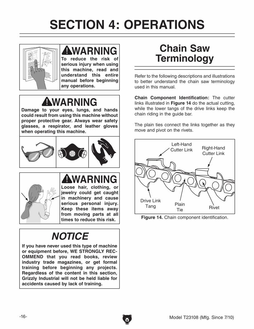
Chain Component Identification: The cutter links illustrated in Figure 14 do the actual cutting, while the lower tangs of the drive links keep the chain riding in the guide bar.
The plain ties connect the links together as they move and pivot on the rivets.
Left-HandCutter Link Right-Hand
Cutter Link
Drive LinkTang Plain
Tie Rivet
Figure 14. Chain component identification.

Model T23108 (Mfg. Since 7/10) -17-
Chain Pitch= This Distance/2
Figure 15. Chain pitch.
Chain Gauge: The chain gauge is the thickness of the drive link tang (see Figure 16) where it fits into the guide bar groove. The guide bar groove must match the width of the chain gauge.
Chain gauges for handheld chain saws range from 0.050" for smaller chains to 0.122" for larger ones.
Drive Link
TangChainGauge
Figure 16. Chain gauge.
Chain Pitch: The distance between any three consecutive rivet centers divided by 2 is known as the chain pitch (see Figure 15).
The chain pitch is the same for all links in the chain. The smallest chain pitch for handheld chain saws is 1⁄4", with 3⁄8" and 0.325" being the most popular.
Top Plate Angle: The profile of the cutter link is shaped like a number "7", and is comprised of the top plate and side plate (see Figure 17). The rake that the top plate angles back from the side plate is called the top plate angle and is generally 25°–35°. This makes a sharp point that begins the cut.
Top PlateCuttingAngle
(Top View) (Side View)
Top PlateAngle
(Front View)
Figure 17. Cutter link top plate angle and cutting angle.
Top Plate Cutting Angle: The top plate cutting angle (see Figure 17) is a chisel-like downward bevel on the underside leading edge of the top plate that usually is 60°. The combination of this cutting angle and the top plate angle serves to remove wood chips from the kerf.
Side Plate Angle: The ground angle of the side plate leading edge is instrumental in forming the cutting point between the side and top plates. This angle is the same as the top plate cutting angle, which is typically 60° (see Figure 18).
Side PlateAngle
Gullet Angle
Figure 18. Cutter link side plate angle, gullet, and depth gauge.

-18- Model T23108 (Mfg. Since 7/10)
Gullet Angle: The cutter gullet (see Figure 18) provides a space for the wood chips so they can be removed by the top plate. On some chains, it is necessary to have a 10° downward bevel on the bottom of the gullet that forces the chips into the path of the top plate for removal.
Depth Gauge: The depth gauge (see Figure 19) is a critical element of the cutter link and is often overlooked in chain saw sharpening. The height of the depth gauge must be below the leading edge of the top plate by the correct amount for your chain saw. Refer to How the Chain Cuts in the next section and Depth Gauge Setting on Page 28 to better understand the purpose of the depth gauge.
After sharpening the cutter, always remember to check, and if necessary, adjust the depth gauge setting.
Depth GaugeSetting
ClearanceAngle
Depth Gauge
Figure 19. Clearance angle and depth gauge setting.
Clearance Angle: The clearance angle (see Figure 19) is the amount that the top plate angles down from the leading edge to the rear of the cut-ter link. This clearance angle allows the cutter link to pivot up into the wood and then down again (refer to How the Chain Cuts in the next section for more information).
Left- & Right-Hand Cutters: Chain saws have left- and right-hand cutter links that together make the cut. The sharpener must be set up differently when sharpening left- and right-hand cutters (see Figure 20) because the angles on the cutters are reversed. It is important to clearly identify the ori-entation of the cutter before sharpening it.
Left-HandCutter
Right-HandCutter
Direction of Chain Travel
Figure 20. Identification of left- and right-hand cutters.

Model T23108 (Mfg. Since 7/10) -19-
How the Chain Cuts The depth gauge setting determines how big of a bite the cutter takes ("2–3"). It is imperative that the depth gauge is set below the leading edge of the top plate by the proper amount so that the cutter can move into the wood.
If the depth gauge is too high or too low, it will prevent the cutter from pivoting forward and self-feeding into the wood. Refer to Depth Gauge Setting on Page 28 for additional information.
Also important is the amount of the clearance angle. The downward slope of the top plate enables the cutter to move into the wood ("2") and then forces it out again ("3–4") to complete the cut.
Always use the chain manufacturer's specifica-tions for the cutter specifications when sharpen-ing the chain.
1
Chain Travel
2 3 4 5
Figure 21. The rocking self-feeding motion of the cutter link during a cutting operation.
As illustrated in Figure 21 below, when the cutting point at the top of the cutter moves against the wood ("1"), the front of the cutter pivots up until the depth gauge meets the wood ("2"), which forces the cutter to pivot even farther into the wood ("3") to make the cut.
When the rear of the top plate meets the wood ("4"), it forces the cutter to continue pivoting for-ward and move out of the kerf, producing wood chips which are carried away by the top plate angle in the final position ("5") to complete the cut.
The goal of this rocking motion is to allow the chain saw to self-feed into the wood and do the work without requiring the operator to force the chain into the wood. This makes the job easier and reduces wear on the saw and chain.

-20- Model T23108 (Mfg. Since 7/10)
Grinding Wheel Selection
The grinding wheels supplied with the T23108 are specific to this sharpener. Refer to the specifica-tions below when purchasing replacements.
Diameter ........................................................5 3⁄4"Bore .................................................................7⁄8"Grit ................................................................. 601⁄8" Thick Wheel Part Number ................. T232513⁄16" Thick Wheel Part Number ................ T232501⁄4" Thick Wheel Part Number .................. T23249
To order replacement grinding wheels, contact Customer Service at (800) 523-4777 or go to www.grizzly.com.
Chain Pitch Chain Gauge
Wheel Thickness
Top Plate & Chain Holder Angle
Top Plate Cutting Angle/
Wheel Tilt
Gullet Angle/Chain Holder Tilt
Depth Gauge
1⁄4" 0.050" 1⁄8" 30° 60° 10° 0.025"
0.325" 0.050" 1⁄8" 25° 60° 10° 0.025"
0.325" 0.058" 1⁄8" 25° 60° 10° 0.025"
0.325" 0.063" 1⁄8" 25° 60° 10° 0.025"3⁄8" 0.050" 1⁄8" 25° 60° 10° 0.025"3⁄8" 0.058" 1⁄8" 25° 60° 10° 0.025"3⁄8" 0.063" 1⁄8" 25° 60° 10° 0.025"
0.404" 0.058" 3⁄16" 25° 60° 10° 0.025"
0.404" 0.063" 3⁄16" 25° 60° 10° 0.025"
0.404" 0.080" 3⁄16" 35° 60° 10° 0.050"3⁄4" 0.122" 1⁄4" 35° 60° 10° 0.070"
1/2
1/21/2
1/21/2
1/21/2
Figure 22. Typical chain saw sharpening specifications.
Grinding wheels that break apart during operation can send high-speed debris at the operator or bystanders. ALWAYS visu-ally inspect the grinding wheel and perform the ring test (see Wheel Inspection & Ring Test on the next page for detailed instruc-tions) before mounting the wheel onto the sharpener. If there is visual damage or the wheel does not pass the ring test—DO NOT use it!
Use the chart in Figure 22 as a general guide when selecting the proper grinding wheel for your chain saw. However, we recommend that you always refer to the chain manufacturer's specifica-tions when setting up the sharpener.

Model T23108 (Mfg. Since 7/10) -21-
Wheel Inspection & Ring Test
Do not assume that a grinding wheel is in sound condition just because it is new or looks okay. Often damage can occur in shipping, with age, or with exposure to moisture, and may not be visible. Inspect every wheel for damage before installation.
First, do a visual inspection. Look for any cracks, chips, nicks or dents in the surface of the wheel. If you see any of these, DO NOT use the wheel.
Second, do a ring test. This test will give you an indication of any internal damage that may not be obvious during a visual inspection. If the wheel does not pass the ring test, DO NOT use the wheel.
To perform a ring test:
1. Make sure the wheel that you test is clean and dry—otherwise, you may get false results.
2. If size permits, balance the wheel with your finger in the center hole. If this is not possible, hang the wheel in the air with a piece of cord or string looped through the bore.
Figure 23. Tapping locations for a ring test.
4. An undamaged wheel will emit a clear metal-lic ring or “ping” sound in each of the four spots. A damaged wheel will respond with a dull thud that has no clear tone.
— If you determine from the results of the ring test that the wheel is damaged, DO NOT USE IT!
3. At the four spots on the wheel shown in Figure 23, gently tap the wheel with a non-metallic object, such as a screwdriver handle or wooden mallet.

-22- Model T23108 (Mfg. Since 7/10)
Top Plate Angle
It is necessary to have the correct backward top plate angle from the side plate (see Figure 24) to form the cutting point where the top and side plates meet, which initiates the cut. This angle continues the cut and forces wood chips away from the kerf.
Top Plate Angleof a Left-Hand Cutter
Side View Top View
Figure 24. Top plate angle of a left-hand cutter.
Note: Always refer to the chain manufacturer's specifications when setting up the sharpener. However, if this information is not available, use the chart in Figure 22 on Page 20 as a general guide.
To set up the chain holder for the top plate angle:
1. DISCONNECT MACHINE FROM POWER!
2. Loosen the chain holder lock knob.
3. Rotate the chain holder to align the mark on the chain holder base with the angle mark on that scale that is right for your chain, then re-tighten the lock knob.
Tip: The chain holder is easier to rotate if the holder tilt is at 0° (see Gullet Angle on Page 24 for detailed instructions).
When setting up the sharpener, the top plate angle is determined by the rotational angle of the chain holder in relation to the grinding wheel.
The chain holder angle scale on the front of the base (see Figure 25) has angle marks to the left and right of 0°. The angle marks on the right side of the scale are used when sharpening left-hand cutters (see Left- & Right-Hand Cutters on Page 18). Conversely, the angle marks on the left side of the scale are used when sharpening right-hand cutters.
Figure 25. Chain holder angle scale.
Chain HolderAngle Scale
Lock Knob
Base Mark

Model T23108 (Mfg. Since 7/10) -23-
Top Plate Cutting Angle
The top plate cutting angle (see Figure 26) is a angle on the top plate underside that usually is ground at 60°. The combination of this cutting angle and the top plate angle serves to continue the cut and remove wood chips from the kerf.
Top PlateCuttingAngle
Figure 26. Top plate cutting angle.
When setting up the sharpener, the top plate cut-ting angle is determined by the tilt of the grind-ing wheel. The grinding wheel tilt is adjusted by changing the angle of the swing arm.
Note: Always refer to the chain manufacturer's specifications when setting up the sharpener. However, if this information is not available, use the chart in Figure 22 on Page 20 as a general guide.
To set the grinding wheel tilt for the top plate cutting angle:
1. DISCONNECT MACHINE FROM POWER!
2. Loosen the swing arm lock knob (see Figure 27).
3. Reference the angle scale on top of the base vertical face to adjust the swing arm and grinding wheel to the correct angle for your chain, then retighten the lock knob.
The grinding wheel tilt setting stays the same when sharpening both left- and right-hand cutters.
Note: There is also the same angle scale on the inside vertical face of the base.
Figure 27. Swing arm angle scale and lock knob.
Lock Knob
Angle Scale

-24- Model T23108 (Mfg. Since 7/10)
Gullet Angle
On most chains, the bottom edge of the cutter gullet must have a 10° downward angle from the outside to the inside of the cutter link, as shown in Figure 28. This angle forces wood chips into the path of the top plate for removal.
GulletAngle
Figure 28. Location of the cutter gullet angle.
To tilt the chain holder for a 10° gullet angle:
1. DISCONNECT MACHINE FROM POWER!
2. Loosen the chain holder lock knob (see Figure 29) three or four rotations.
3. Tilt the chain holder so that the correct cast-ing tilt mark aligns with the base mark, as illustrated in Figure 30. This will produce a 10° gullet angle when sharpening.
4. Retighten the lock knob, then check to make sure the tilt marks are properly aligned.
5. To bring the chain holder back to 0°, align the casting center tilt mark with the base mark.
The gullet angle is determined by the tilt of the chain holder. The chain holder can be tilted to 0° or 10° in and out.
Note: Always refer to the chain manufacturer's specifications when setting up the sharpener. However, if this information is not available, use the chart in Figure 22 on Page 20 as a general guide.
If your chain requires a 10° gullet angle, align the outside casting tilt mark with the base mark when sharpening right-hand cutters (see Figures 29–30). Conversely, align the inside casting tilt mark with the base mark when sharpening left-hand cutters.
Outside Tilt MarkAligned for
Right-Hand Cutter
Inside Tilt MarkAligned for
Left-Hand Cutter
Figure 30. Chain holder tilt marks aligned for left- and right-hand cutters.
Figure 29. Aligning the chain holder tilt marks.
Base MarkLock
Knob
Casting Tilt Marks

Model T23108 (Mfg. Since 7/10) -25-
Sharpening Operation
In the following sharpening procedure, you adjust the sharpener settings to grind the correct angles for the chain, then sharpen each cutter link one at a time.
After properly sharpening all of the cutter links, you need to check, and if necessary, adjust the depth gauge setting—the distance between the top plate leading edge and the top of the depth gauge. Even though the cutter may be properly sharpened, if the depth gauge setting is not cor-rect, the chain will not effectively cut the wood.
The T23108 is not designed to adjust the depth gauge setting, and it is beyond the scope of this manual to explain the many methods to perform this important task (refer to Depth Gauge Setting on Page 28 for additional information).
To sharpen the chain cutters:
1. Clean the chain with a non-flammable clean-er to remove any oil, dirt, and grime, then use compressed air to thoroughly dry the chain.
2. Visually inspect the chain and replace any severely damaged links that could break apart during sharpening. If replacement is not possible, use a different chain.
3. Make sure all of the cutter top plates will be at least 1⁄4" in length after the sharpening proce-dure is completed. This is the recommended minimum top plate length to avoid the cutter link from breaking apart during cutting opera-tion.
— If you suspect that any cutter top plate will be shorter than 1⁄4" in length after being sharpened, replace that link or replace the chain.
4. DISCONNECT MACHINE FROM POWER!
5. Read and understand all the safety instruc-tions listed in the beginning of this manual and included with the chain saw owner's manual.
6. Make sure the sharpener is firmly secured to the workbench.
7. Select and test the grinding wheel that is right for your chain, as instructed in the Wheel Inspection & Ring Test procedure on Page 21.
8. After successful completion of Step 7, install the grinding wheel onto the sharpener, as instructed in the Installing Grinding Wheel procedure on Page 14.
NOTICEAlways refer to the chain manufacturer's specifications when setting up the sharp-ener. However, if this information is not available, use the chart in Figure 22 on Page 20 as a general guide.
Note: The following instructions begin by sharpening the right-hand cutters. If you choose to start with left-hand cutters, keep in mind the chain holder rotation angle and, if used, chain holder tilt will be different.
9. Rotate the chain holder counterclockwise (looking down on it) and align it with the cor-rect rotation angle mark on the scale for the chain, as instructed in the Top Plate Angle procedure on Page 22. This setting deter-mines the top plate angle.
10. If required for your chain, set the grinding wheel tilt to provide the correct gullet angle, as instructed in the Gullet Angle procedure on Page 24.

-26- Model T23108 (Mfg. Since 7/10)
Note: Attaining the proper setting for the advancement guide is a matter of patience and trial-and-error. This setting is critical to properly sharpen the cutters, so take the time to find the correct setting.
The goal is to position the cutter in relation to the grinding wheel so that all three angles—the top plate angle, the top plate cutting angle, and the gullet angle—will be correctly sharpened.
14. With the machine still disconnected from power, lower the grinding wheel into the gul-let.
— If the wheel matches the gullet profile and is against the top and side plates when com-pletely lowered, the advancement guide is properly set for now. Tighten the knob lock nut on the adjustment controls behind the guide to secure the setting.
— If the wheel hits the top plate or depth gauge and does not completely lower into the gullet, or it is not against the top and side plates, adjust the advancement guide until it successfully stops the chain in the proper position. Be sure to secure the set-ting by tightening the knob lock nut.
13. Position the edge of the advancement guide behind the cutter to be sharpened, then pull the chain to the left until the guide catches and stops the chain (see Figure 32).
11. Use the clamp lever (see Figure 31) to set the gap between the clamp plates to match the chain gauge, which will allow the chain to easily move along the top of the clamping bars in the same manner it moves along the chain saw bar.
12. Locate the cutter link with the shortest top plate length and position the chain so that this link is under the grinding wheel. This will be the first link sharpened.
Use chalk or a marker to note the first link to be sharpened so that you will know when you are finished with that side of cutters.
Note: If all of the top plates are approximately the same length, then start with any cutter. The concern is that all top plates are the same length when the sharpening operation is complete to ensure they cut away the same amount during operation.
If the grinding wheel should break apart during operation, the only thing between you and the flying debris of the wheel are the wheel and arbor safety guards. ALWAYS make sure the wheel and arbor safety guards are properly secured in place before con-necting the machine to power!
Figure 31. Clamp lever and clamp plates.
Clamp Lever
Clamp Plates
Figure 32. Advancement guide and controls.
AdvancementGuide
GuideAdjustment Controls
Model T23108 (Mfg. Since 7/10) -27-
15. Rotate the clamp lever to the right to firmly secure the chain between the clamp plates of the chain holder.
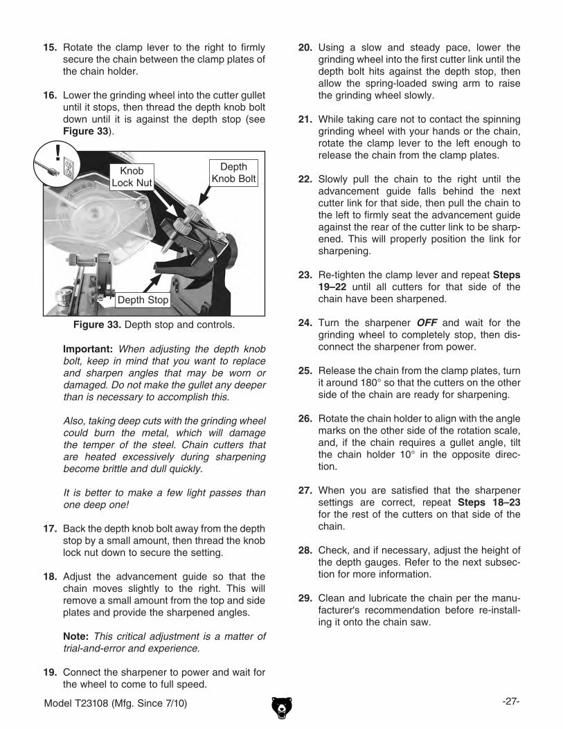
16. Lower the grinding wheel into the cutter gullet until it stops, then thread the depth knob bolt down until it is against the depth stop (see Figure 33).
Important: When adjusting the depth knob bolt, keep in mind that you want to replace and sharpen angles that may be worn or damaged. Do not make the gullet any deeper than is necessary to accomplish this.
Also, taking deep cuts with the grinding wheel could burn the metal, which will damage the temper of the steel. Chain cutters that are heated excessively during sharpening become brittle and dull quickly.
It is better to make a few light passes than one deep one!
17. Back the depth knob bolt away from the depth stop by a small amount, then thread the knob lock nut down to secure the setting.
18. Adjust the advancement guide so that the chain moves slightly to the right. This will remove a small amount from the top and side plates and provide the sharpened angles.
Note: This critical adjustment is a matter of trial-and-error and experience.
19. Connect the sharpener to power and wait for the wheel to come to full speed.
20. Using a slow and steady pace, lower the grinding wheel into the first cutter link until the depth bolt hits against the depth stop, then allow the spring-loaded swing arm to raise the grinding wheel slowly.
21. While taking care not to contact the spinning grinding wheel with your hands or the chain, rotate the clamp lever to the left enough to release the chain from the clamp plates.
22. Slowly pull the chain to the right until the advancement guide falls behind the next cutter link for that side, then pull the chain to the left to firmly seat the advancement guide against the rear of the cutter link to be sharp-ened. This will properly position the link for sharpening.
23. Re-tighten the clamp lever and repeat Steps 19–22 until all cutters for that side of the chain have been sharpened.
24. Turn the sharpener OFF and wait for the grinding wheel to completely stop, then dis-connect the sharpener from power.
25. Release the chain from the clamp plates, turn it around 180° so that the cutters on the other side of the chain are ready for sharpening.
26. Rotate the chain holder to align with the angle marks on the other side of the rotation scale, and, if the chain requires a gullet angle, tilt the chain holder 10° in the opposite direc-tion.
27. When you are satisfied that the sharpener settings are correct, repeat Steps 18–23 for the rest of the cutters on that side of the chain.
28. Check, and if necessary, adjust the height of the depth gauges. Refer to the next subsec-tion for more information.
29. Clean and lubricate the chain per the manu-facturer's recommendation before re-install-ing it onto the chain saw.
Figure 33. Depth stop and controls.
DepthKnob Bolt
KnobLock Nut
Depth Stop

-28- Model T23108 (Mfg. Since 7/10)
Depth Gauge Setting
As explained in How the Chain Cuts on Page 19, the depth gauge of the cutter link forces the cutter to pivot forward and self-feed into the wood.
The depth gauge setting is the difference in height between the top plate leading edge and the top of the depth gauge. If this setting (see Figure 34) is too high or too low, the cutter will not properly pivot and self-feed into the wood.
Top PlateDepth Gauge
Setting
DepthGauge
Figure 34. Depth gauge setting.
Adjusting the depth gauge setting requires the top of the depth gauge is made lower than the top plate leading edge by a specific amount. This amount changes as the top plate leading edge is ground back with successive sharpenings.
It is beyond the scope of this manual to present the many different methods of maintaining the proper depth gauge setting. However, it is impor-tant to state that properly maintaining this setting is critical to the efficient operation of the chain saw. No matter how well the chain is sharpened, if the depth gauge setting is not properly main-tained, the chain will not be able to efficiently cut the wood.
We strongly recommend that you research the many methods and tools for maintaining the prop-er depth gauge setting for your chain, and choose the best solution that works for you.
Clamp Plate Adjustment
If necessary, the pressure of the chain holder clamp plates can be adjusted to suit your needs.
To adjust the clamp plate pressure:
1. DISCONNECT MACHINE FROM POWER!
2. Loosen the two cap screws shown in Figure 35. This will allow the inner clamp plate to be adjusted in the next step.
3. Loosen the locking hex nut on the adjustment bolt, then thread the bolt in to force the inner clamp toward the outer clamp.
4. Re-tighten the locking hex nut and the two outside cap screws.
5. Test the clamping pressure of the plates with your chain, and if necessary, repeat this pro-cedure until the clamping pressure is right for your chain.
Figure 35. Clamp plate components.
Adjustment Bolt& Locking Hex Nut
OutsideCap
Screws

Model T23108 (Mfg. Since 7/10) -29-
SECTION 5: MAINTENANCE
For optimum performance from your machine, follow this maintenance schedule and refer to any specific instructions given in this section.
Daily Check:• Loose mounting bolts.• Damaged or worn grinding wheel.• Loose lock knobs and bolts.• Worn or damaged wires or switch.• Any other unsafe condition.
Schedule
Cleaning the Model T23108 is relatively easy. Disconnect the machine from power and wipe down the surfaces with a damp shop rag, then dry them with a clean, dry cloth.
Cleaning
Lubrication
There are not any parts on this sharpener that require lubrication by the end user.
The bearings of the sharpener motor were lubri-cated and permanently sealed at the factory and do not need any further attention unless they need replacement.
Dressing Wheels
The edge profile and surface condition of the grinding wheel (see Figure 36) is critical in main-taining the proper shape of the top plate, side plate, and gullet when sharpening.
Grinding Wheel Edge Profile
Correct Worn
Figure 36. Grinding wheel edge profile.
With use, the abrasive surface of the grinding wheel becomes embedded with material from the chain, which reduces its effectiveness. In addi-tion, the side and bottom edge deform and fails to effectively sharpen the cutter edges. When this happens, the sharpened surfaces become burned or discolored, instead of having a clean, silver fin-ish. Additionally, the angles will not be properly sharpened.
Use the included wheel dressing block to expose a new abrasive surface on the wheel and to re-form the side and edge profiles.
Always disconnect power to the machine before performing maintenance. Failure to do this may result in serious person-al injury.

-30- Model T23108 (Mfg. Since 7/10)
Review the troubleshooting and procedures in this section to fix or adjust your machine if a problem devel-ops. If you need replacement parts or you are unsure of your repair skills, then feel free to call our Technical Support at (570) 546-9663.
SECTION 6: SERVICE
Troubleshooting
Symptom Possible Cause Possible SolutionMachine does not start or a breaker trips.
1. Power supply switched OFF or at fault.2. Plug/receptacle at fault/wired wrong.3. Start capacitor at fault.4. Wall circuit breaker tripped.5. Wiring open/has high resistance.6. Motor ON/OFF switch at fault.7. Motor connection wired wrong.8. Motor at fault.
1. Ensure power supply is ON/has correct voltage.2. Test for good contacts; correct the wiring.3. Test/replace if faulty.4. Ensure circuit size is correct/replace weak breaker.5. Check/fix broken, disconnected, or corroded wires. 6. Replace switch.7. Correct motor wiring connections.8. Test/repair/replace.
Machine stalls or is overloaded.
1. Motor wired incorrectly.2. Plug/receptacle at fault.3. Motor bearings at fault.4. Operation overloading motor.
5. Motor overheated.6. Motor at fault.
1. Wire motor correctly.2. Test for good contacts/correct wiring.3. Test/repair/replace.4. Dress grinding wheel or replace it; reduce the
feed rate; make sure sharpener settings are correct for the chain.
5. Clean motor, let cool, and reduce workload.6. Test/repair/replace.
Machine has vibration or noisy operation.
1. Motor or component loose.
2. Grinding wheel at fault/arbor hole not round.
3. Incorrectly mounted to workbench.
4. Motor fan rubbing on fan cover.5. Motor bearings at fault.
6. Motor shaft bent.
1. Inspect/replace damaged bolts/nuts, and re-tighten with thread locking fluid.
2. Inspect/dress/replace grinding wheel.
3. Tighten mounting hardware; use shims if necessary.
4. Fix/replace fan cover; replace loose/damaged fan.5. Test by rotating shaft; rotational grinding/loose
shaft requires bearing replacement.6. Test with dial indicator and replace motor.
Cutter edges burned or discolored; not being properly sharpened.
1. Not using correct grinding wheel.
2. Sharpener settings not correct.
3. User placing grinding wheel against cutter too long or too hard during sharpening operation.
1. Use the correct size and grit grinding wheel; inspect, and if necessary, dress or replace wheel.
2. Make sure the sharpener settings are correct for the chain.
3. Raise the grinding wheel away from the cutter as soon as the depth bolt hits the depth stop.
Chain saw not cutting or self-feeding.
1. Sharpener settings not correct.
2. Depth gauge settings not correct.3. Chain dulls quickly.
1. Make sure the sharpener settings are correct for the chain.
2. Check and adjust the all depth gauge settings.3. Cutter links over-heated during sharpening;
replace links/chains.

Model T23108 (Mfg. Since 7/10) -31-
These pages are current at the time of printing. However, in the spirit of improvement, we may make chang-es to the electrical systems of future machines. Study this section carefully. If there are differences between your machine and what is shown in this section, call Technical Support at (570) 546-9663 for assistance BEFORE making any changes to the wiring on your machine.
SECTION 7: WIRING
SHOCK HAZARD. Working on wiring that is con-nected to a power source is extremely dangerous. Touching electrified parts will result in personal injury including but not limited to severe burns, electrocution, or death. Disconnect the power from the machine before servicing electrical com-ponents!
MODIFICATIONS. Modifying the wiring beyond what is shown in the diagram may lead to unpre-dictable results, including serious injury or fire. This includes the installation of unapproved after-market parts.
WIRE CONNECTIONS. All connections must be tight to prevent wires from loosening during machine operation. Double-check all wires dis-connected or connected during any wiring task to ensure tight connections.
CIRCUIT REQUIREMENTS. You MUST follow the requirements at the beginning of this manualwhen connecting your machine to a power source.
WIRE/COMPONENT DAMAGE. Damaged wires or components increase the risk of serious per-sonal injury, fire, or machine damage. If you notice that any wires or components are damaged while performing a wiring task, replace those wires or components.
MOTOR WIRING. The motor wiring shown inthese diagrams is current at the time of printingbut may not match your machine. If you find thisto be the case, use the wiring diagram inside the motor junction box.
CAPACITORS/INVERTERS. Some capacitorsand power inverters store an electrical charge for up to 10 minutes after being disconnected from the power source. To reduce the risk of being shocked, wait at least this long before working on capacitors.
EXPERIENCING DIFFICULTIES. If you are expe-riencing difficulties understanding the information included in this section, contact our Technical Support at (570) 546-9663.
Wiring Safety Instructions
The photos and diagrams included in this section are best viewed in color. You can view these pages in color at www.grizzly.com.

-32- Model T23108 (Mfg. Since 7/10)READ ELECTRICAL SAFETY ON PAGE 31!
T23108 Wiring Diagram
GndLight
ON/OFFSwitch
110V Motor
Neutral
Hot
Ground
110VACNEMA 5-15 Plug
(As Recommended)
Sta
rt C
apac
ito
r12
MF
D 2
50V
AC
IN
OUT
LN
Figure 37. T23108 wiring.

Model T23108 (Mfg. Since 7/10) -33-
SECTION 8: PARTS
Breakdown Diagram
1
2
3
4
5
6
7
8
9
10
11
13
14
15
16
17
18
20
21
24
2529
3031
3233
34
35
3637 38
39
46
46
47
49
51
52
54
56
58
60 6162
63
6465
66
67
68
69
71
14
46
21
47
53
40
53
53
53
49
49
32
36 55
19
22
23
2627
28
42
43 44
45
50
57
59
72
73
16-1
16-2

-34- Model T23108 (Mfg. Since 7/10)
Parts ListREF PART # DESCRIPTION REF PART # DESCRIPTION1 PT23108001 SWING ARM 36 PT23108036 KNOB LOCK NUT M6-12 PT23108002 WHEEL SAFETY GUARD 37 PT23108037 COMPRESSION SPRING3 PT23108003 ARBOR SAFETY GUARD 38 PT23108038 TORSION SPRING4 PT23108004 WIRING COVER 39 PT23108039 DOUBLE END STUD M6-1 X 805 PT23108005 LIGHT BRACKET 40 PT23108040 BOLT SLEEVE6 PT23108006 LIMITER 42 PT23108042 KNOB M10-1.257 T23249 GRINDING WHEEL 7/8"B 60G 1/4" X 5-3/4" 43 PT23108043 BOTTOM SWING ARM ANGLE SCALE8 PT23108008 INNER FLANGE 44 PT23108044 TOP SWING ARM ANGLE SCALE9 PT23108009 OUTER FLANGE 45 PT23108045 CHAIN HOLDER ANGLE SCALE10 PT23108010 KNOB BOLT M8-1.25 X 70 46 PCAP50M CAP SCREW M5-.8 X 1011 PT23108011 KNOB LOCK NUT M8-1.25 47 PB96M HEX BOLT M5-.8 X 1013 PT23108013 SWING ARM HANDLE 49 PCAP07M CAP SCREW M6-1 X 3014 PT23108014 LIGHT SOCKET ASSEMBLY 50 PCAP50M CAP SCREW M5-.8 X 1015 PT23108015 ON/OFF SWITCH 51 PB126M HEX BOLT M8-1.25 X 4016 PT23108016 MOTOR 230W 110V 60HZ 52 PB31M HEX BOLT M10-1.5 X 4016-1 PT23108016-1 MOTOR FAN COVER 53 PN01M HEX NUT M6-116-2 PT23108016-2 MOTOR FAN 54 PN32M HEX NUT M14-217 PT23108017 SWING ARM PIVOT BRACKET 55 PN03M HEX NUT M8-1.2518 PT23108018 PIVOT AXLE 56 PW01M FLAT WASHER 8MM19 PT23108019 KNOB M10-1.5 57 PWF10M FENDER WASHER 10MM20 PT23108020 TORSION SPRING 58 PT23108058 THIN HEX NUT M14-221 PT23108021 BUSHING 59 PSTB004M STEEL BALL 5MM22 PT23108022 BASE 60 PT23108060 WHEEL DRESSING STONE23 PT23108023 CHAIN HOLDER BASE ASSEMBLY 61 PT23108061 CHAIN GAUGE24 PT23108024 CHAIN HOLDER CASTING 62 PAW05M HEX WRENCH 5MM25 PT23108025 KNOB BOLT M6-1 X 50 63 PAW04M HEX WRENCH 4MM26 PT23108026 CURVED WASHER 10MM 64 PT23108064 LIGHT BULB 110V 15W27 PT23108027 COMPRESSION SPRING 65 PT23108065 S CAPACITOR 12M 250V 1-1/4 X 2-1/228 PT23108028 COMPRESSION SPRING 66 PT23108066 POWER CORD 12AWG 3C 45" 5-1529 PT23108029 CHAIN CLAMP STUD 67 PT23108067 STRAIN RELIEF30 PT23108030 CHAIN CLAMP LEVER 68 T23250 GRINDING WHEEL 7/8"B 60G 3/16" X 5-3/4"31 PT23108031 KNOB M8-1.25 69 T23251 GRINDING WHEEL 7/8"B 60G 1/8" X 5-3/4"32 PT23108032 CHAIN CLAMP PLATE 71 PWR8 COMBO WRENCH 8MM33 PT23108033 COMPRESSION SPRING 72 PT23108072 MACHINE ID LABEL34 PT23108034 ADVANCEMENT GUIDE BRACKET 73 PT23108073 SAFETY GLASSES LABEL35 PT23108035 ADVANCEMENT GUIDE

CU
T A
LON
G D
OT
TE
D L
INE
Name _____________________________________________________________________________
Street _____________________________________________________________________________
City _______________________ State _________________________ Zip _____________________
Phone # ____________________ Email _________________________________________________
Model # ____________________ Order # _______________________ Serial # __________________
WARRANTY CARD
The following information is given on a voluntary basis. It will be used for marketing purposes to help us develop better products and services. Of course, all information is strictly confidential.
1. How did you learn about us? ____ Advertisement ____ Friend ____ Catalog ____ Card Deck ____ Website ____ Other:
2. Which of the following magazines do you subscribe to?
3. What is your annual household income? ____ $20,000-$29,000 ____ $30,000-$39,000 ____ $40,000-$49,000 ____ $50,000-$59,000 ____ $60,000-$69,000 ____ $70,000+
4. What is your age group? ____ 20-29 ____ 30-39 ____ 40-49 ____ 50-59 ____ 60-69 ____ 70+
5. How long have you been a woodworker/metalworker? ____ 0-2 Years ____ 2-8 Years ____ 8-20 Years ____20+ Years
6. How many of your machines or tools are Grizzly? ____ 0-2 ____ 3-5 ____ 6-9 ____10+
7. Do you think your machine represents a good value? _____Yes _____No
8. Would you recommend Grizzly Industrial to a friend? _____Yes _____No
9. Would you allow us to use your name as a reference for Grizzly customers in your area? Note: We never use names more than 3 times. _____Yes _____No
10. Comments: _____________________________________________________________________
_________________________________________________________________________________
_________________________________________________________________________________
_________________________________________________________________________________
____ Cabinetmaker & FDM____ Family Handyman____ Hand Loader____ Handy____ Home Shop Machinist____ Journal of Light Cont.____ Live Steam____ Model Airplane News____ Old House Journal____ Popular Mechanics
____ Popular Science____ Popular Woodworking____ Precision Shooter____ Projects in Metal____ RC Modeler____ Rifle____ Shop Notes____ Shotgun News____ Today’s Homeowner____ Wood
____ Wooden Boat____ Woodshop News____ Woodsmith____ Woodwork____ Woodworker West____ Woodworker’s Journal____ Other:

TAPE ALONG EDGES--PLEASE DO NOT STAPLE
FOLD ALONG DOTTED LINE
FOLD ALONG DOTTED LINE
GRIZZLY INDUSTRIAL, INC.P.O. BOX 2069BELLINGHAM, WA 98227-2069
PlaceStampHere
Name_______________________________
Street_______________________________
City______________State______Zip______
Send a Grizzly Catalog to a friend:

WARRANTY AND RETURNS
Grizzly Industrial, Inc. warrants every product it sells for a period of 1 year to the original purchaser from the date of purchase. This warranty does not apply to defects due directly or indirectly to misuse, abuse, negligence, accidents, repairs or alterations or lack of maintenance. This is Grizzly’s sole written warranty and any and all warranties that may be implied by law, including any merchantability or fitness, for any par-ticular purpose, are hereby limited to the duration of this written warranty. We do not warrant or represent that the merchandise complies with the provisions of any law or acts unless the manufacturer so warrants. In no event shall Grizzly’s liability under this warranty exceed the purchase price paid for the product and any legal actions brought against Grizzly shall be tried in the State of Washington, County of Whatcom.
We shall in no event be liable for death, injuries to persons or property or for incidental, contingent, special, or consequential damages arising from the use of our products.
To take advantage of this warranty, contact us by mail or phone and give us all the details. We will then issue you a “Return Number,’’ which must be clearly posted on the outside as well as the inside of the carton. We will not accept any item back without this number. Proof of purchase must accompany the merchandise.
The manufacturers reserve the right to change specifications at any time because they constantly strive to achieve better quality equipment. We make every effort to ensure that our products meet high quality and durability standards and we hope you never need to use this warranty.
Please feel free to write or call us if you have any questions about the machine or the manual.
Thank you again for your business and continued support. We hope to serve you again soon.
WARRANTY AND RETURNS