Embed Size (px)
Citation preview

COPYRIGHT © NOVEMBER, 2008 BY GRIZZLY INDUSTRIAL, INC., REVISED MARCH, 2015 (TR)WARNING: NO PORTION OF THIS MANUAL MAY BE REPRODUCED IN ANY SHAPE
OR FORM WITHOUT THE WRITTEN APPROVAL OF GRIZZLY INDUSTRIAL, INC.#CRTR11351 PRINTED IN INDIA
MODEL T10057
MT#2 TAPPING ATTACHMENTOWNER'S MANUAL

This manual provides critical safety instructions on the proper setup, operation, maintenance, and service of this machine/tool. Save this document, refer to it often, and use it to instruct other operators.
Failure to read, understand and follow the instructions in this manual may result in fire or serious personal injury—including amputation, electrocution, or death.
The owner of this machine/tool is solely responsible for its safe use. This responsibility includes but is not limited to proper installation in a safe environment, personnel training and usage authorization, proper inspection and maintenance, manual availability and compre-hension, application of safety devices, cutting/sanding/grinding tool integrity, and the usage of personal protective equipment.
The manufacturer will not be held liable for injury or property damage from negligence, improper training, machine modifications or misuse.
Some dust created by power sanding, sawing, grinding, drilling, and other construction activities contains chemicals known to the State of California to cause cancer, birth defects or other reproductive harm. Some examples of these chemicals are:
• Lead from lead-based paints.• Crystalline silica from bricks, cement and other masonry products.• Arsenic and chromium from chemically-treated lumber.
Your risk from these exposures varies, depending on how often you do this type of work. To reduce your exposure to these chemicals: Work in a well ventilated area, and work with approved safety equip-ment, such as those dust masks that are specially designed to filter out microscopic particles.

Model T10057 MT#2 Tapping Attachment -1-
Safety Instructions for Tapping Attachments1. UNDERSTANDING CONTROLS.
Make sure you understand the use and operation of all controls.
2. SAFETY ACCESSORIES. Always use a chip guard in addition to your safety glasses when drilling or tap-ping to prevent bodily injury.
3. WORK HOLDING. Before starting the machine, be certain the workpiece has been properly clamped to the table. NEVER hold the workpiece by hand when drilling or tapping.
4. CHUCK KEY SAFETY. Always remove the chuck key, arbor wedge, or any tools immediately after use.
5. SPINDLE SPEEDS. Select the spin-dle speed that is appropriate for the type of work and material. Allow the machine to gain full speed before using the tapping attachment.
6. POWER DISRUPTION. In the event of a local power outage during use of the drill press, turn OFF all switches to avoid possible sudden start up once power is restored.
For Your Own Safety Read Instruction Manual Before Operating This Equipment
The purpose of safety symbols is to attract your attention to possible hazard-ous conditions. This manual uses a series of symbols and signal words which are intended to convey the level of importance of the safety messages. The progression of symbols is described below. Remember that safety messages by themselves do not eliminate danger and are not a substitute for proper accident prevention measures.
Indicates a potentially hazardous situation which, if not avoided, MAY result in minor or moderate injury. It may also be used to alert against unsafe practices.
Indicates a potentially hazardous situation which, if not avoided, COULD result in death or serious injury.
Indicates an imminently hazardous situation which, if not avoided, WILL result in death or serious injury.
This symbol is used to alert the user to useful infor-mation about proper operation of the equipment.
SAFETY
NOTICE

Model T10057 MT#2 Tapping Attachment-2-
7. SPINDLE DIRECTION CHANGES. Never reverse spindle direction when drilling or tapping a workpiece.
8. TOOL HOLDING. Always use the proper tools for the material you are drilling or tapping. Make sure they are held firmly in the chuck or tapping attachment jaws.
9. CLEAN-UP. DO NOT clear chips by hand. Use a brush or vacuum, and never clear chips while the machine is running.
10. MACHINE MAINTENANCE. Never operate the drill press with damaged or worn parts. Keep your machine and tapping attachment in proper working condition. Perform routine inspec-tions and maintenance promptly. Put away adjustment tools after use.
11. DISCONNECT POWER. Make sure the drill press is turned OFF, discon-nected from its power source and all moving parts have come to a com-plete stop before starting any inspec-tion, adjustment, or maintenance pro-cedure on the tapping attachment.
12. AVOIDING ENTANGLEMENT. Keep loose clothing articles such as sleeves, belts or jewelry items away from the drill press spindle and tap-ping attachment. Never wear gloves when operating the drill press.
13. BE ATTENTIVE. DO NOT leave the machine running unattended.
14. STOPPING SPINDLE. DO NOT stop the machine using your hand against the chuck or tapping attachment.
15. CUTTING TOOL INSPECTION. Inspect drills and cutters for sharp-ness, chips, or cracks before each use. Replace dull, chipped, or cracked cutting tools immediately. Handle new cutting tools with care. Leading edges are very sharp and can cause lacerations.
16. EXPERIENCING DIFFICULTIES. If you are experiencing difficulties in setup or operation, stop using the machine! Contact our Technical Support at (570) 546-9663.
Safety Instructions for Tapping Attachments
No list of safety guidelines can be complete. Every shop environment is differ-ent. Like all machines there is danger associated with the drill press and tapping attachment. Accidents are frequently caused by lack of familiarity or failure to pay attention. Use this tapping attachment with respect and caution to lessen the possibility of operator injury. If normal safety precautions are overlooked or ignored, serious personal injury may occur.

Model T10057 MT#2 Tapping Attachment -3-
INTRODUCTION
Arbor .................................................. MT#2Jaw Type .............................Spring LoadedMaximum Speed .......................... 700 RPMConstruction ..................High Carbon SteelSteel Hardness ......................... 46-56 HRCOverall Length ..........................9" (225mm)Stop Lever Length .................8 3⁄4" (220mm)Reverse Type .....................Auto ReversingTypical Concentricity .....................+⁄- 0.001"Head Diameter ....................2.750" (70mm)Tapping Capacity (Metric) ......... M3 to M12Tapping Capacity (SAE) ................ 1⁄8" to 1⁄2"Drill Chuck Capacity ............... 13⁄32" (10mm)Oil Type ..............................ISO 68 Way Oil
We are proud to offer the Grizzly Model T10057 Tapping Attachment. This model is part of a growing Grizzly family of fine tools. When used according to the guidelines set forth in this manual, you can expect years of trouble-free, enjoyable operation and proof of Grizzly’s commitment to customer satisfaction.
It is our pleasure to provide this manual with the Model T10057. It was written to encourage safety considerations and guide you through general operating procedures and maintenance.
The specifications, details, and photo-graphs in this manual represent the Model T10057 as supplied when the manual was prepared. However, owing to Grizzly’s pol-icy of continuous improvement, changes may be made at any time with no obligation on the part of Grizzly.
Foreword
Tool Data
If you have any comments regarding this manual, please contact us:
Grizzly Industrial, Inc.C/O Technical Documentation Manager
P.O. Box 2069 Bellingham, WA 98227-2069Email: [email protected]
Most importantly, we stand behind our tools. If you have any service questions or parts requests, please call or write us at the location listed below.
Grizzly Industrial, Inc.1203 Lycoming Mall Circle
Muncy, PA 17756Phone: (570) 546-9663
Fax: (800) 438-5901E-Mail: [email protected] Site: http://www.grizzly.com
Contact Info
Read the manual before operation. Become familiar with this tapping attachment, its safety instructions, and its operation before beginning any work. Serious personal injury may result if safety or operational informa-tion is not understood or followed.

Model T10057 MT#2 Tapping Attachment-4-
SETUP
Inventory
Your new item was carefully packaged for safe shipping. If you discover any damage after you have signed for delivery, immedi-ately call Customer Service at (570) 546-9663 for advice.
Save the containers and all packing materi-als for possible inspection by the carrier or its agent. Otherwise, filing a freight claim can be difficult.
When you are completely satisfied with the condition of the shipment, you should inventory the contents.
Unpacking
Figure 1. Model T10057 inventory.
A
B C D
F
B
E
After you open the tapping attachment box, you should find the following.
Model T10057 Inventory (Figure 1)A. Tapping Attachment ........................... 1B. Cheater Rods .................................... 2C. Stop Lever .......................................... 1D. Stop Lever Nut ................................... 1F. Hex Wrench 4mm .............................. 1E. Drill Chuck Spanner Wrench ............. 1

Model T10057 MT#2 Tapping Attachment -5-
Installation
1. DISCONNECT THE DRILL PRESS FROM POWER.
2. Insert the tapping attachment MT-2 arbor into the drill press as normal.
3. Insert the threaded end of the stop lever into the tapping attachment, and secure it with the stop lever nut (Figure 2).
4. Insert the handle so it rests against the left side of the drill press column (Figure 2). This lever must be held stationary during tapping operations.
7. Loosen the drill chuck 1⁄4-turn. The tap will now have some slight wobble or "Float" to it. This lateral play is manda-tory to prevent the tap from shearing during tapping procedures.
8. Adjust the drill press depth stop so the tap will not bottom out in the hole.
9. Using an oil gun, add two or thee drops of HP Milcot 52 or an equivalent oil into the ball oiler on the tapping attach-ment.
10. Rotate the cup nut (Figure 3) to increase or decrease the clutch tension depending on the tap size, thread pitch, material to be tapped.
Note: The numbers stamped on the side of the clutch nut (Figure 3) are for your personal reference and do not cor-relate to any specific tap size or thread pitch. You may want to make some test passes to get an idea about which set-ting will work best for your needs.
For small taps, loosen the clutch nut to decrease the clutch spring tension. For large taps, tighten the clutch nut to increase the clutch spring tension.
The tapping attachment is now ready for use. Follow all drill press safety precau-tions.
Note: Any fixed object can be used providing that the object allows the drill press spindle to raising and lower.
5. For tapping, insert the tap into the tap-ping attachment (Figure 3) until it stops and the tap flats are aligned with the two tap retainer jaws. Next snug the drill chuck with your finger tips to center the tap.
6. Tighten the tap retainer (Figure 3) with a 4mm hex wrench so the tap retaining jaws clamp against the flats on the tap.
Figure 2. Tapping attachment installed.
Rotation
StopLever Nut
StopLever
Figure 3. Tapping ready for use.
CupNut
Drill Chuck
TapRetainer
Lock Screw

Model T10057 MT#2 Tapping Attachment-6-
OPERATIONS
This tapping attachment allows you to first install a drill bit into the taper attachment chuck, and then drill a hole. Next, without the inconvenience of losing spindle-to-work-piece registration, the drill bit is removed with the spanner wrench, and then the tap is installed into the tapping attachment. The tap is held by the tap retainer, which is tightened by means of a 4mm hex wrench. Set the tapping speed on the drill press, apply thread cutting lubricant if required (Figure 4). When threading is complete, pull up on the rack handle and the tapping attachment automatically reverses. The tap rotates out of the workpiece twice as fast as the initial threading pass.
General Operation
To reduce the risk of personal inju-ry or property damage when using taps and drill bits, take the follow-ing precautions:• When using the tapping attach-
ment for drilling, do not exceed 700 RPM.
• Always wear safety glasses or a face shield when using a tap or drill bit.
• Use the correct size drill bit for each tap. Attempting to cut threads in an incorrectly sized hole can cause the tap to snap and eject steel splinters.
• Be sure to use the correct lubri-cant when drilling and cutting threads.
• Always keep drill bits and taps sharpened to ensure that drill bits cut properly sized holes and that tap threads do not bind and cause the tap to break.
• Never allow children to play with drill bits or taps.
Spindle RPM = Feed Speed (SFM)
(0.26 x Tap Diameter)
Always follow the tap and drill bit manufac-turer's speed recommendations. However, to avoid injury, do not exceed the maximum tapping attachment speed of 700 RPM.
The chart shown in Figure 4 is only intend-ed as a guide. The optimum speed will always depend on various factors, includ-ing tap diameter, threading pressure, mate-rial hardness, material quality, and desired finish. Often, when tapping, different types of lubrication is required. Use the formula below and the table in Figure 4 to find a close spindle speed and suggested lubricant.
Tapping Speed and Lubricant Chart
Cutting lubricants can be a potent and extreme-ly poisonous solution to humans and animals. Use personal protective equipment when han-dling coolant to prevent infections or poisoning.

Model T10057 MT#2 Tapping Attachment -7-
Fig
ure
4. T
appi
ng s
peed
and
lubr
ican
t cha
rt.
Mat
eria
l to
be
Tap
ped
Fee
d S
pee
d(S
FM
)T
app
ing
L
ub
rica
nts
Pla
stic
s/F
iber
glas
s50
-70
Dry
, Fre
ezin
g S
pray
, Liq
uid
Soa
p
Alu
min
um
70-9
0S
olub
le O
il
Alu
min
um A
lloys
50-7
0S
olub
le O
il, L
ight
Bas
e O
il, L
ard
Oil
Bra
ss60
-100
Nea
t Cut
ting
Oils
Bro
nze
30-4
0
Cop
per
60-8
0
Gun
Gra
de M
etal
50-6
0S
olub
le O
il, L
ight
Bas
e O
il, L
ard
Oil
Gre
y C
ast
Iron
30-6
0D
ry
Mal
leab
le I
ron
20-4
0S
olub
le O
il, P
araf
fin-B
ased
Lub
rican
tM
agne
sium
Allo
y50
-70
Nim
onic
Allo
y10
-12
Hig
h P
ress
ure
Cut
ting
Oil
Allo
y C
ast
Iron
15-3
0
Cut
ting
Oils
(S
ulfu
r-B
ased
)
Mild
Ste
el30
-50
Car
bon
Ste
el u
p to
4%
20-4
0
Car
bon
Ste
el u
p to
7%
20-3
0
Car
bon
Ste
el 7
% a
nd H
ighe
r15
-25
Ste
el A
lloys
60T
15-2
5
Ste
el A
lloys
60T
and
Hig
her
10-1
5
Sta
inle
ss S
teel
10-2
0
Tool
Ste
els
15-2
5
Model T10057 MT#2 Tapping Attachment-8-
ACCESSORIES
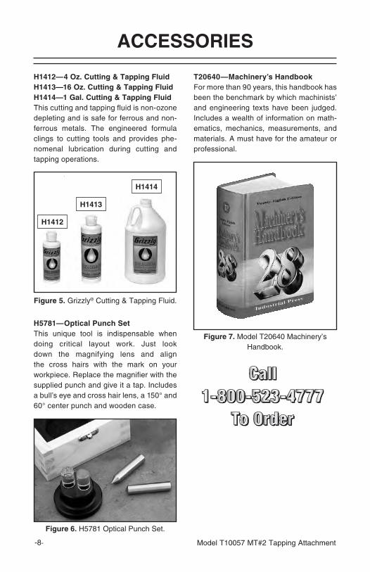
H5781—Optical Punch Set This unique tool is indispensable when doing critical layout work. Just look down the magnifying lens and align the cross hairs with the mark on your workpiece. Replace the magnifier with the supplied punch and give it a tap. Includes a bull’s eye and cross hair lens, a 150° and 60° center punch and wooden case.
Figure 6. H5781 Optical Punch Set.
T20640—Machinery’s HandbookFor more than 90 years, this handbook has been the benchmark by which machinists’ and engineering texts have been judged. Includes a wealth of information on math-ematics, mechanics, measurements, and materials. A must have for the amateur or professional.
Figure 7. Model T20640 Machinery’s Handbook.
Figure 5. Grizzly® Cutting & Tapping Fluid.
H1412
H1413
H1414
H1412—4 Oz. Cutting & Tapping FluidH1413—16 Oz. Cutting & Tapping FluidH1414—1 Gal. Cutting & Tapping FluidThis cutting and tapping fluid is non-ozone depleting and is safe for ferrous and non-ferrous metals. The engineered formula clings to cutting tools and provides phe-nomenal lubrication during cutting and tapping operations.

Model T10057 MT#2 Tapping Attachment -9-
PARTS
20
14
2
3
13
12
11 108
49
16
15
718
19
17
1
6
5
22
REF PART # DESCRIPTION REF PART # DESCRIPTION1 PT10057001 ARBOR MT#2 12 PT10057012 GUIDE BUSHING2 PT10057002 CLUTCH PACK 13 PT10057013 SPINDLE3 PT10057003 CUP NUT 14 PT10057014 SPECIAL SCREW4 PT10057004 CAM 15 PT10057015 CHUCK NUT5 PT10057005 CAM PIN 16 PT10057016 JAW SET6 PT10057006 MAIN BODY 17 PT10057017 STOP LEVER NUT7 PT10057007 GEAR WHEEL 18 PT10057018 STOP LEVER8 PT10057008 WHEEL PIN 19 PT10057019 CHEATER ROD9 PT10057009 CLUTCH SLEEVE 20 PT10057020 SPANNER WRENCH10 PT10057010 CLUTCH PIN 22 PT10057022 HEX WRENCH 4MM11 PT10057011 BALL OILER

Grizzly Industrial, Inc. warrants every product it sells for a period of 1 year to the original purchaser from the date of purchase. This warranty does not apply to defects due directly or indirectly to misuse, abuse, negligence, accidents, repairs or alterations or lack of mainte-nance. This is Grizzly’s sole written warranty and any and all warranties that may be implied by law, including any merchantability or fitness, for any particular purpose, are hereby limited to the duration of this written warranty. We do not warrant or represent that the merchandise complies with the provisions of any law or acts unless the manufacturer so warrants. In no event shall Grizzly’s liability under this warranty exceed the purchase price paid for the prod-uct and any legal actions brought against Grizzly shall be tried in the State of Washington, County of Whatcom.
We shall in no event be liable for death, injuries to persons or property or for incidental, contingent, special, or consequential damages arising from the use of our products.
To take advantage of this warranty, contact us by mail or phone and give us all the details. We will then issue you a “Return Authorization Number,” which must be clearly posted on the outside as well as the inside of the carton. We will not accept any item back without this number. Proof of purchase must accompany the merchandise.
The manufacturers reserve the right to change specifications at any time because they constantly strive to achieve better quality equipment. We make every effort to ensure that our products meet high quality and durability standards and we hope you never need to use this warranty.
Please feel free to write or call us if you have any questions about the machine or the manual.
Grizzly Industrial, Inc.1203 Lycoming Mall Circle
Muncy, PA 17756Phone: (570) 546-9663
Fax: (800) 438-5901
E-Mail: [email protected]
Web Site: http://www.grizzly.com
Thank you again for your business and continued support. We hope to serve you again soon!
WARRANTY AND RETURNS