Embed Size (px)
Citation preview

0099001202-03
READ THE ENTIRE MANUAL BEFORE USING THIS PRODUCT. FAILURE TO DO SO COULD RESULT IN SERIOUS INJURY OR DEATH.
OWNER’S MANUAL
Model OMAX-6A-1B Single Bank Charger With Quick DisconnectModel OMAX-12A-1B Single Bank ChargerModel OMAX-25A-1B Single Bank ChargerModel OMAX-50A-1B Single Bank ChargerModel OMAX-40AS-3B Three Bank Sequencing ChargerModel OMAX-50AS-3B Three Bank Sequencing ChargerFor 12 Volt Odyssey® Batteries
Please call Customer Service at 800-621-5485 for instructions on returning the charger.
Warrensburg, MO 64093 USA

• 2 •
IMPORTANT: READ AND SAVE THIS SAFETY AND INSTRUCTION MANUAL.SAVE THESE INSTRUCTIONS – This manual will show you how to use your charger safely and effectively. Please read, understand and follow these instructions and precautions carefully, as this manual contains important safety and operating instructions. The safety messages used throughout this manual contain a signal word, a message and an icon.The signal word indicates the level of the hazard in a situation.
Indicates an imminently hazardous situation which, if not avoided, will result in death or serious injury to the operator or bystanders.Indicates a potentially hazardous situation which, if not avoided, could result in death or serious injury to the operator or bystanders.Indicates a potentially hazardous situation which, if not avoided, could result in moderate or minor injury to the operator or bystanders.Indicates a potentially hazardous situation which, if not avoided, could result in damage to the equipment or vehicle or property damage.
Pursuant to California Proposition 65, this product contains chemicals known to the State of California to cause cancer and birth defects or other reproductive harm. Wash hands after handling.
1. IMPORTANT SAFETY INSTRUCTIONS – SAVE THESE INSTRUCTIONS This manual contains important safety and operating instructions.
RISK OF ELECTRIC SHOCK OR FIRE.1.1 Keep out of reach of children.1.2 Do not expose the charger to rain or snow.1.3 Use only recommended attachments. Use of an attachment not recommended or sold by Schumacher® Electric Corporation may result in a risk of fire, electric shock or injury to persons or damage to property.
1.4 To reduce the risk of damage to the electric plug or cord, pull by the plug rather than the cord when disconnecting the charger.
1.5 An extension cord should not be used unless absolutely necessary. Use of an improper extension cord could result in a risk of fire and electric shock. If an extension cord must be used, make sure:
• That the pins on the plug of the extension cord are the same number, size and shape as those of the plug on the charger.
• That the extension cord is properly wired and in good electrical condition.• That the wire size is large enough for the AC ampere rating of the charger as
specified in section 8.1.6 To reduce the risk of electric shock, unplug the charger from the outlet before attempting
any maintenance or cleaning. Simply turning off the controls will not reduce this risk.1.7 Do not operate the charger with a damaged cord or plug; have the cord or plug replaced
immediately by a qualified service person. (Call customer service at 1-800-621-5485.)1.8 Do not operate the charger if it has received a sharp blow, been dropped or otherwise
damaged in any way; take it to a qualified service person. (Call customer service at 1-800-621-5485.)
1.9 Do not disassemble the charger; take it to a qualified service person when service or repair is required. Incorrect reassembly may result in a risk of fire or electric shock. (Call customer service at 1-800-621-5485.)

• 3 •
RISK OF EXPLOSIVE GASES.1.10 WORKING IN THE VICINITY OF A LEAD-ACID BATTERY IS DANGEROUS. BATTERIES GENERATE EXPLOSIVE GASES DURING NORMAL BATTERY OPERATION. FOR THIS REASON, IT IS OF UTMOST IMPORTANCE THAT YOU FOLLOW THE INSTRUCTIONS EACH TIME YOU USE THE CHARGER.
1.11 To reduce the risk of a battery explosion, follow these instructions and those published by the battery manufacturer and the manufacturer of any equipment you intend to use in the vicinity of the battery. Review the cautionary markings on these products and on the engine.
1.12 This charger employs parts, such as switches and circuit breakers, that tend to produce arcs and sparks. If used in a garage, locate this charger 18 inches (46 cm) or more above floor level.
2. PERSONAL PRECAUTIONSRISK OF EXPLOSIVE GASES.2.1 NEVER smoke or allow a spark or flame in the vicinity of a battery or engine.2.2 Remove personal metal items such as rings, bracelets, necklaces and watches when working with a lead-acid battery. A lead-acid battery can produce a short-circuit current high enough to weld a ring or the like to metal, causing a severe burn.
2.3 Be extra cautious to reduce the risk of dropping a metal tool onto the battery. It might spark or short-circuit the battery or other electrical part that may cause an explosion.
2.4 Use this charger for charging LEAD-ACID batteries only. It is not intended to supply power to a low voltage electrical system other than in a starter-motor application. Do not use this battery charger for charging dry-cell batteries that are commonly used with home appliances. These batteries may burst and cause injury to persons and damage to property.
2.5 NEVER charge a frozen battery.2.6 NEVER overcharge a battery.2.7 Consider having someone nearby to come to your aid when you work near a lead-acid
battery.2.8 Have plenty of fresh water and soap nearby in case battery acid contacts your skin,
clothing or eyes.2.9 Wear complete eye and body protection, including safety goggles and protective
clothing. Avoid touching your eyes while working near the battery.2.10 If battery acid contacts your skin or clothing, immediately wash the area with soap and
water. If acid enters your eye, immediately flood the eye with cold running water for at least 10 minutes and get medical attention right away.
2.11 If battery acid is accidentally swallowed, drink milk, the whites of eggs or water. DO NOT induce vomiting. Seek medical attention immediately.
3. PREPARING TO CHARGERISK OF CONTACT WITH BATTERY ACID. BATTERY ACID IS A HIGHLY CORROSIVE SULFURIC ACID.3.1 If it is necessary to remove the battery from the vehicle to charge it, always remove the grounded terminal first. Make sure all of the accessories in the vehicle are off to prevent arcing.3.2 Be sure the area around the battery is well ventilated while the battery is being charged.
3.3 Clean the battery terminals before charging the battery. During cleaning, keep airborne corrosion from coming into contact with your eyes, nose and mouth. Use baking soda and water to neutralize the battery acid and help eliminate airborne corrosion. Do not touch your eyes, nose or mouth.
3.4 This charger is only designed to charge AGM/VRLA batteries that do not allow for the battery caps to be removed. For any other type of battery, follow the battery manufacturer’s instruction for maintenance.

• 4 •
3.5 Read, understand and follow all instructions for the charger, battery, vehicle and any equipment used near the battery and charger. Study all of the battery manufacturer’s specific precautions while charging and recommended rates of charge.
3.6 Determine the voltage of the battery by referring to the vehicle owner’s manual and make sure that the output voltage selector switch is set to the correct voltage. If the charger has an adjustable charge rate, charge the battery in the lowest rate first.
3.7 Make sure that the charger cable clips make tight connections.
4. CHARGER LOCATIONRISK OF EXPLOSION AND CONTACT WITH BATTERY ACID.4.1 Locate the charger as far away from the battery as the DC cables permit.4.2 Never place the charger directly above the battery being charged; gases from the battery will corrode and damage the charger.
4.3 Do not set the battery on top of the charger.4.4 Never allow battery acid to drip onto the charger when reading the electrolyte specific
gravity or filling the battery.4.5 Do not operate the charger in a closed-in area or restrict the ventilation in any way.
5. DC CONNECTION PRECAUTIONS5.1 Connect and disconnect the DC output clips only after setting all of the charger switches
to the “off” position (if applicable) and removing the AC plug from the electrical outlet. Never allow the clips to touch each other.
5.2 Attach the clips to the battery and chassis, as indicated in sections 6 and 7.
6. FOLLOW THESE STEPS WHEN BATTERY IS INSTALLED IN VEHICLE.A SPARK NEAR THE BATTERY MAY CAUSE A BATTERY EXPLOSION. TO REDUCE THE RISK OF A SPARK NEAR THE BATTERY:6.1 Position the AC and DC cables to reduce the risk of damage by the hood, door and moving or hot engine parts. NOTE: If it is necessary to close the
hood during the charging process, ensure that the hood does not touch the metal part of the battery clips or cut the insulation of the cables.
6.2 Stay clear of fan blades, belts, pulleys and other parts that can cause injury.6.3 Check the polarity of the battery posts. The POSITIVE (POS, P, +) battery post usually
has a larger diameter than the NEGATIVE (NEG, N, -) post.6.4 Determine which post of the battery is grounded (connected) to the chassis. If the
negative post is grounded to the chassis (as in most vehicles), see step 6.5. If the positive post is grounded to the chassis, see step 6.6.
6.5 For a negative-grounded vehicle, connect the POSITIVE (RED) clip from the battery charger to the POSITIVE (POS, P, +) ungrounded post of the battery. Connect the NEGATIVE (BLACK) clip to the vehicle chassis or engine block away from the battery. Do not connect the clip to the carburetor, fuel lines or sheet-metal body parts. Connect to a heavy gauge metal part of the frame or engine block.
6.6 For a positive-grounded vehicle, connect the NEGATIVE (BLACK) clip from the battery charger to the NEGATIVE (NEG, N, -) ungrounded post of the battery. Connect the POSITIVE (RED) clip to the vehicle chassis or engine block away from the battery. Do not connect the clip to the carburetor, fuel lines or sheet-metal body parts. Connect to a heavy gauge metal part of the frame or engine block.
6.7 Connect charger AC supply cord to electrical outlet.6.8 When disconnecting the charger, turn all switches to off, disconnect the AC cord, remove
the clip from the vehicle chassis and then remove the clip from the battery terminal.

• 5 •
7. FOLLOW THESE STEPS WHEN BATTERY IS OUTSIDE VEHICLE.A SPARK NEAR THE BATTERY MAY CAUSE A BATTERY EXPLOSION. TO REDUCE THE RISK OF A SPARK NEAR THE BATTERY:7.1 Check the polarity of the battery posts. The POSITIVE (POS, P, +) battery post usually has a larger diameter than the NEGATIVE (NEG, N, -) post.
7.2 Attach at least a 24-inch (61 cm) long 6-gauge (AWG) (13 mm2) insulated battery cable to the NEGATIVE (NEG, N, -) battery post.
7.3 Connect the POSITIVE (RED) charger clip to the POSITIVE (POS, P, +) post of the battery.7.4 Position yourself and the free end of the cable you previously attached to the NEGATIVE
(NEG, N, -) battery post as far away from the battery as possible – then connect the NEGATIVE (BLACK) charger clip to the free end of the cable.
7.5 Do not face the battery when making the final connection. 7.6 Connect charger AC supply cord to electrical outlet.7.7 When disconnecting the charger, always do so in the reverse order of the connecting
procedure and break the first connection while as far away from the battery as practical.7.8 A marine (boat) battery must be removed and charged on shore. To charge it onboard
requires equipment specially designed for marine use.
8. AC POWER CORD CONNECTIONSRISK OF ELECTRIC SHOCK OR FIRE.8.1 This battery charger is for use on a nominal 120-volt circuit. The plug must be plugged into an outlet that is properly installed in accordance with all local codes and ordinances. The plug pins must fit the receptacle (outlet).
Never alter the AC cord or plug provided – if it does not fit the outlet, have a proper outlet installed by a qualified electrician. An improper connection can result in a risk of an electric shock or electrocution. NOTE: Pursuant to Canadian Regulations, use of an adapter plug is not allowed in Canada. Use of an adapter plug in the United States is not recommended and should not be used.
8.2 Recommended minimum AWG size for extension cord:
AC input rating, amperes* AWG size of cord, Length of cord, feet (m)
At least But less than 25 (7.6) 50 (15.2) 100 (30.5) 150 (45.6)
0 2 18 18 18 16
2 3 18 18 16 14
3 4 18 18 16 14
4 5 18 18 14 12
5 6 18 16 14 12
6 8 18 16 12 10
8 10 18 14 12 10
*If the input rating of a charger is given in watts rather than in amperes, the corresponding ampere rating is to be determined by dividing the wattage rating by the voltage rating - for example:
1200 watts/120 volts = 10 amperes
9. ASSEMBLY INSTRUCTIONSRemove all cord wraps and uncoil the cables prior to using the battery charger.

• 6 •
10. CONTROL PANELLED Indicators (All Models)
• CHECK (red) LED lit: Indicates that the battery is not properly connected to the charger.• CHECK (red) LED flashing: Indicates that the charger is in abort mode.• CHARGING (yellow) LED lit: Indicates that the charger has detected a battery and
is charging it.• CHARGED (green) LED lit: Indicates that the battery is fully charged and the
charger is in maintain mode.NOTE: See the Operating Instructions section for a complete description of the charger modes.Display Button (Models OMAX-12A-1B, OMAX-25A-1B)Press this button to set the digital display to show one of the following.
• Battery % – The display shows an estimate of the percent of charge of the battery connected to the charger battery clamps.
• Voltage – The display shows the voltage at the battery clamps in DC volts.Display Button (Models OMAX-50A-1B, OMAX-40AS-3B, OMAX-50AS-3B)Press this button to set the digital display to show one of the following.
• Percent: The display shows an estimate of the percent of charge of the battery connected to the charger battery clamps.
• Volts: The display shows the voltage at the battery clamps in DC volts.• Amps: The display shows charge current provided by the charger in DC amps.
Charge Button (Models OMAX-6A-1B, OMAX-12A-1B, OMAX-25A-1B)Press this button to set the charger to one of the following settings.
• On: Indicates the charger is in charge mode.• Off: Indicates the charger is in test mode.
Output Button (Model OMAX-50A-1B)Press this button to set the charger to one of the following settings.
• On: Indicates the charger is in charge mode.• Off: Indicates the charger is in test mode.
Bank Button (Models OMAX-40AS-3B, OMAX-50AS-3B)Press this button to set the charger to one of the following settings for each bank.
• Charge: Indicates that bank is in charge mode.• Test: Indicates that bank is in test mode.
11. OPERATING INSTRUCTIONS
This battery charger must be properly assembled in accordance with the assembly instructions before it is used.Charging1. Make sure that you have an Odyssey® battery.2. Ensure that all of the charger components are in place and in good working
condition, for example, the plastic boots on the battery clips.3. Connect the battery following the precautions listed in sections 6 and 7.4. Connect the AC power following the precautions listed in section 8. Make sure to
place the charger on a dry, non-flammable surface like metal or concrete. 5. Select the appropriate settings for your battery.6. To disconnect, reverse the procedure. NOTE: Do not connect one OMAX-40AS-3B or OMAX-50AS-3B sequencing charger to two or more batteries connected in a series. If the positive terminal of one battery is connected to the negative terminal of another battery, then they are connected in a series and must not be connected to the same OMAX-40AS-3B or OMAX-50AS-3B charger.
• 7 •
Permanent Ring Connectors (Model OMAX-6A-1B)The ring connectors permanently attach to the battery, providing easy access to quickly charge your battery. This application is appopriate for motorcycles, lawn tractors, ATVs and snowmobiles.1. To permanently attach to a battery, loosen and remove each nut from the bolt at the
battery terminal. 2. Connect the red POSITIVE connector ring to the POSITIVE battery terminal. 3. Connect the black NEGATIVE connector ring to the NEGATIVE battery terminal. 4. Replace and tighten the nuts to secure. 5. Connect the cable to the end of the charger output cord. Take care to keep the wires
and plug away from metal and moving parts. 6. Plug the charger power cord into a 120V AC electrical wall outlet. Make sure to place the
charger on a dry, non-flammable surface, like metal or concrete.
12. CHARGER OPERATIONThe Ultimizer™ charger is custom designed to safely and quickly charge your Odyssey® battery using a three-step profile. It is very important that you not use this charger with any battery other than Odyssey® as it can damage other lead acid batteries.In the first step, called the bulk phase, the battery is charged at up to the nominal charge rate (6, 12, 25, 40 or 50 amps) until the voltage reaches about 14.7V. The charger then switches to the second step, called the absorption phase. In this step the charger continues to charge the battery at about 14.7V until either the charge current drops to 100 milliamps or the charger has been in the absorption phase for 4 hours, whichever occurs first. The charger then enters into the maintain mode phase at 13.5-13.8V. The battery can be left connected to the charger indefinitely. The OMAX-40AS-3B and OMAX-50AS-3B chargers were designed to charge up to and including three 12V batteries in sequence. When charging in sequence, only one of the three banks is on at a time. Every few minutes, the charger will alternate which output is on and which outputs are off. Each output will continue to turn on and off every few minutes as long as more than one bank is set to charge. If only one bank is connected to a battery and turned on, then it will charge continuously.NOTE: Since each bank is on only half or one third of the time during charging, the absorption phase could last 8 or 12 hours instead of only 4 hours. Battery Connection IndicatorIf the charger does not detect a properly connected battery, the CHECK LED will light. Charging will not begin while the CHECK LED is on.Aborted Charge (Model OMAX-6A-1B)If charging cannot be completed normally, charging will abort. When charging aborts, the charger’s output is shut off and the CHECK LED will blink. In that state, the charger ignores all buttons. To reset after an aborted charge, unplug the charger from the AC outlet, wait a few moments and plug it back in.Aborted Charge (Models OMAX-12A-1B, OMAX-25A-1B)If charging cannot be completed normally, charging will abort. When charging aborts, the charger’s output is shut off and the CHECK LED will blink and the digital display will show 18.8 and blink on and off (at opposite times). In that state, the charger ignores all buttons. To reset after an aborted charge, unplug the charger from the AC outlet, wait a few moments and plug it back in.Aborted Charge (Models OMAX-50A-1B)If charging cannot be completed normally, charging will abort. When charging aborts, the charger’s output is shut off, the CHECK LED will blink and the digital display will show 8.8.8 and blink on and off (at opposite times). In that state, the charger ignores all buttons. To reset after an aborted charge, unplug the charger from the AC outlet, wait a few moments and plug it back in.

• 8 •
Aborted Charge (Models OMAX-40AS-3B, OMAX-50AS-3B)If charging cannot be completed normally, charging will abort. When charging aborts, the charger’s output is shut off, only the CHECK LED for that bank will blink and the digital display will show 8.8.8 and blink on and off (at opposite times). In that state, the charger ignores all buttons. To reset after an aborted charge without affecting the other banks, disconnect the clips for the aborted bank from the battery.Desulfation ModeIf the battery is left discharge for an extended period of time, it could become sulfated and not accept a normal charge. If the charger detects a sulfated battery, the charger will switch to a special mode of operation designed for such batteries. Activation of the special desulfation mode is indicated by the CHARGING LED blinking. If successful, normal charging will resume after the battery is desulfated. The CHARGING LED will then stop blinking and light continuously. Desulfation could take up to 10 hours. If desulfation fails, charging will abort and the CHECK LED will blink.Completion of ChargeCharge completion is indicated by the CHARGED LED. When lit, the charger has switched to the Maintain Mode of operation.Maintain Mode (Float-Mode Monitoring)When the CHARGED LED is lit, the charger has started Maintain Mode. In this mode, the charger keeps the battery fully charged by delivering a small current when necessary.NOTE: The maintain mode technology utilized in the Enersys® chargers allows you to safely charge and maintain a healthy battery for extended periods of time. However, problems with your battery, electrical problems in your vehicle, improper connections or other unanticipated conditions could cause excessive current draws, as such, occasionally monitoring your battery and the charging process is recommended.Using The Battery Voltage TesterOverviewThis battery charger has a built-in voltmeter to test your battery’s state of charge. The charger does not have a built in load tester. As such, a recently charged battery could have a temporarily high voltage due to what is known as “surface charge”. The voltage of such a battery will gradually drop during the period immediately after the charging system is disengaged. Consequently, the tester could display inconsistent values for such a battery. For a more accurate reading, the surface charge should be removed by temporarily creating a load on the battery, such as by turning on lights or other accessories.Testing Sequence: There are three basic steps required to test the battery state of charge:1. With the charger unplugged from the AC outlet, connect the charger to the battery
following the instructions given in Sections 6 and 7.2. Plug the charger AC power cord into the AC outlet.3. Read the voltage on the digital display or press the display mode button to set the
tester to BATTERY % to read the voltage as a percent of charge (on the OMAX-6A-1B read the six Status LEDs).
Tester and Charger: When first turned on, the unit operates only as a tester, not as a charger. To continue to use it only as a tester, avoid pressing the CHARGE button (OUTPUT button on the OMAX-50A-1B and BANK button on the OMAX-40AS-3B and OMAX-50AS-3B).Power-Up Idle Time Limit: If no button is pressed within 10 minutes after the battery charger is first powered up, the charger will automatically switch from tester to charger, if a battery is connected (the same applies to each bank of the OMAX-40AS-3B and OMAX-50AS-3B).Tester Without Time Limit: If the DISPLAY button is pressed within the first 10 minutes after the battery charger is powered up, the unit will remain a tester (not a charger) indefinitely, unless the charge button is pressed (OUTPUT button on the OMAX-50A-1B and BANK button on the OMAX-40AS-3B and OMAX-50AS-3B).Testing After Charging: After the unit has been changed from tester to charger (by pressing the CHARGE or OUTPUT button), it remains a charger. To change the battery charger back to a tester, press the CHARGE or OUTPUT button again (the same applies to each bank of the OMAX-40AS-3B and OMAX-50AS-3B).

• 9 •
Initial Percent Calculation: When a battery % is calculated for the first time after connecting a battery, the digital display will show dashes (“- - -“ or “- -“ depending on the model) for a period as long as several seconds while the tester analyzes the battery.General Charging NotesRelay (All Models except OMAX-25A-1B)The charger is equipped with a relay that turns the charge current on and off to the battery. It is normal to occasionally hear a clicking sound when the relay is turned on or off.Fan (Model OMAX-25A-1B)It is normal for the fan to be on while the charger is charging (as long as the voltage is above 9V). The fan is normally off at other times but may cycle on and off due to temperature or other conditions (see Over-temperature Protection). Keep the area near the charger clear of obstructions to allow the fan to operate efficiently.Over-temperature Protection (All Models except OMAX-6A-1B and OMAX-12A-1B)The charger is equipped with an internal thermocouple that monitors the temperature. If the temperature rises above a preset level the charge current will be reduced to allow the charger to cool. If the temperature cannot be reduced at the lower charge rate the charge current will be turned off until the temperature is down to a normal level. The charger will then continue where it left off. For best results do not place the charger in direct sunlight or enclosed spaces with high temperatures.
13. MAINTENANCE INSTRUCTIONS13.1 After use and before performing maintenance, unplug and disconnect the battery
charger (see sections 6, 7 and 8).13.2 Use a dry cloth to wipe all battery corrosion and other dirt or oil from the battery clips,
cords, and the charger case.13.3 Ensure that all of the charger components are in place and in good working condition,
for example, the plastic boots on the battery clips.13.4 Servicing does not require opening the unit, as there are no user-serviceable parts.13.5 All other servicing should be performed by qualified service personnel.
14. MOVING AND STORAGE INSTRUCTIONS14.1 Store the charger unplugged, in an upright position. The cord will still conduct electricity
until it is unplugged from the outlet. 14.2 Store inside, in a cool, dry place (unless you’re using an on-board Marine Charger).14.3 Do not store the clips on the handle, clipped together, on or around metal, or clipped
to cables. 14.4 If the charger is moved around the shop or transported to another location, take care to
avoid/prevent damage to the cords, clips and charger. Failure to do so could result in personal injury or property damage.
• 10 •
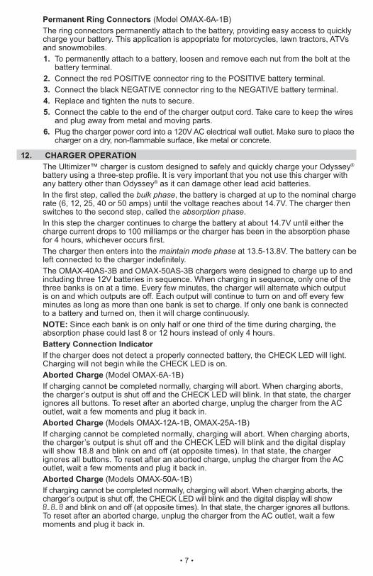
15. TROUBLESHOOTINGModels: All
PROBLEM POSSIBLE CAUSE REASON/SOLUTIONCHECK (red) LED is on. Clips are not making a good
connection to the battery. Connections are reversed. Battery is severely discharged or defective.
Check for a poor connection to the battery. Make sure the connection points are clean. Unplug the charger and reverse the clips.Have the battery checked.
The battery is connected and the charger is on but is not charging.
The charger is in Test Mode not Charge Mode.
Press the CHARGE, OUTPUT or BANK button until the ON or CHARGE LED lights.
Indicator lights are lit in an erratic manner not explained in the manual.
A button may have been pressed as the charger was plugged into the 120V AC outlet.
Make sure nothing is touching the control panel, then unplug the charger, wait a moment, and plug it back in.
CHECK (red) LED always flashes before the battery is completely charged.
This will happen if the battery did not reach a full charge within 24 hours. That may be due to a very large battery or a bank of batteries requiring more power than the charger can deliver in 24 hours.Battery may be defective.
Reset the charger by unplugging the charger from the 120V AC outlet, waiting a moment, then plugging it back in and starting the charge cycle again.
Have the battery checked.
The CHARGED (green) LED turns on a few minutes after connecting the charger to the battery.
The battery may be fully charged or recently charged leaving the battery voltage high enough to appear to be fully charged.
If the battery is in a vehicle, turn the headlights on for a few minutes to reduce the battery voltage and try charging it again.
The measured current is much lower than expected.
The charger has reached the maximum voltage and is reducing the current.The charger detected an over-temperature condition and has reduced the current to allow the charger to cool.
No problem; this is a normal condition.
See the “Over-temperature Protection” section of the manual.
The CHECK (red) LED is blinking. NOTE: The digital display (if present) blinks when the CHECK LED blinks.
Indicates the charger is in Abort Mode.
See “Aborted Charge” in the OPERATING INSTRUCTIONS” Section.
• 11 •
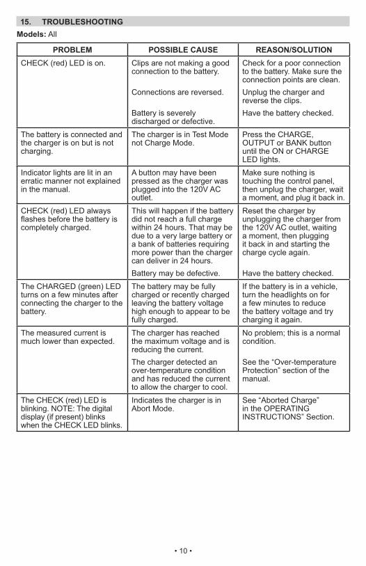
Models: All, except OMAX-25A-1B
PROBLEM POSSIBLE CAUSE REASON/SOLUTIONThe charger is making an audible clicking sound.
The charger has a relay that turns the current to the battery on and off.
No problem; this is a normal condition.
Models: OMAX-6A-1B and OMAX-12A-1B
PROBLEM POSSIBLE CAUSE REASON/SOLUTIONThe charger was unplugged from the 120V AC power source but the display is still on.
The battery is supplying power to the display.
Disconnect the battery charger cables from the battery.
Models: OMAX-25A-1B
PROBLEM POSSIBLE CAUSE REASON/SOLUTIONThe fan turns on and off unexpectedly.
The fan turns on and off as determined by the software and temperature.
No problem; this is a normal condition.
Models: OMAX-40AS-3B and OMAX-50AS-3B
PROBLEM POSSIBLE CAUSE REASON/SOLUTIONA battery is connected and the charger is on but is not charging.
The battery is connected to a bank that is set to TEST Mode.Two or more batteries are being charged in sequence.
Press the appropriate BANK button to set that bank to CHARGE Mode.This is normal. The banks charge one at a time for a few minutes each, then stop while the next bank charges.
The AMPS value displayed is much lower than the charge rate listed on the charger.
The battery being charged is small.
The battery being charged is approaching full charge.
It is normal for the charge rate not to reach the listed level when charging small batteries.It is normal for the charge rate to go to a lower rate as the battery nears full charge.
The AMPS value displayed does not match the value measured with an external meter.
AMPS values should be consistent for one unit, but variations between units prevent precise current measurement for every unit.
Use the AMPS displayed to monitor the charging progress, not for precise current measurement.

• 12 •
16. BEFORE RETURNING FOR REPAIRS16.1 When a charging problem arises, make certain that the battery is capable of accepting
a normal charge. Double check all connections, the AC outlet for a full 120-volts, the charger clips for correct polarity and the quality of the connections from the cables to the clips and from the clips to the battery system. The clips must be clean.
16.2 When a battery is very cold, partially charged or sulfated, it will not draw the full rated amperes from the charger. It is both dangerous and damaging to a battery to force higher amperage into it than it can effectively use in recharging.
16.3 When an UNKNOWN OPERATING PROBLEM arises, please read the complete manual and call the customer service number for information. This will usually eliminate the need for return.
If the above solutions do not eliminate the problem, or for information about troubleshooting, call toll-free from anywhere in the U.S.A.
1-800-621-5485 7:00 am to 5:00 pm Central Time Monday through Friday
For REPAIR OR RETURN, contact Customer Service at 1-800-621-5485. DO NOT SHIP UNIT until you receive RETURN AUTHORIZATION from Customer Service at Schumacher Electric Corporation.

• 13 •
17. LIMITED WARRANTYWARRANTY NOT VALID IN MEXICO.SCHUMACHER ELECTRIC CORPORATION, 801 BUSINESS CENTER DRIVE, MOUNT PROSPECT, IL 60056-2179, MAKES THIS LIMITED WARRANTY TO THE ORIGINAL RETAIL PURCHASER OF THIS PRODUCT. THIS LIMITED WARRANTY IS NOT TRANSFERABLE OR ASSIGNABLE.Schumacher Electric Corporation (the “Manufacturer”) warrants this battery charger for 3 years from the date of purchase at retail against defective material or workmanship that may occur under normal use and care. If your unit is not free from defective material or workmanship, Manufacturer’s obligation under this warranty is solely to repair or replace your product with a new or reconditioned unit at the option of the Manufacturer. It is the obligation of the purchaser to forward the unit, along with proof of purchase and mailing charges prepaid to the Manufacturer or its authorized representatives in order for repair or replacement to occur.Manufacturer does not provide any warranty for any accessories used with this product that are not manufactured by Schumacher Electric Corporation and approved for use with this product. This Limited Warranty is void if the product is misused, subjected to careless handling, repaired, or modified by anyone other than Manufacturer or if this unit is resold through an unauthorized retailer.Manufacturer makes no other warranties, including, but not limited to, express, implied or statutory warranties, including without limitation, any implied warranty of merchantability or implied warranty of fitness for a particular purpose. Further, Manufacturer shall not be liable for any incidental, special or consequential damage claims incurred by purchasers, users or others associated with this product, including, but not limited to, lost profits, revenues, anticipated sales, business opportunities, goodwill, business interruption and any other injury or damage. Any and all such warranties, other than the limited warranty included herein, are hereby expressly disclaimed and excluded. Some states do not allow the exclusion or limitation of incidental or consequential damages or length of implied warranty, so the above limitations or exclusions may not apply to you. This warranty gives you specific legal rights and it is possible you may have other rights which vary from this warranty.THIS LIMITED WARRANTY IS THE ONLY EXPRESS LIMITED WARRANTY AND THE MANUFACTURER NEITHER ASSUMES OR AUTHORIZES ANYONE TO ASSUME OR MAKE ANY OTHER OBLIGATION TOWARDS THE PRODUCT OTHER THAN THIS WARRANTY.
Schumacher Electric Corporation Customer Service 1-800-621-5485
Monday–Friday 7:00 a.m. to 5:00 p.m. CSTSchumacher® and the Schumacher Logo are registered trademarks
of Schumacher Electric Corporation.
DO NOT RETURN THIS PRODUCT TO THE STORE!Call Customer Service for assistance: 800-621-5485

• 14 •

• 15 •
3 YEAR LIMITED WARRANTY PROGRAM
REGISTRATION MODEL: _____________________DESCRIPTION: ________________________
This is the only express limited warranty, and the manufacturer neither assumes nor authorizes anyone to assume or make any other obligation. There is no other warranty, other than what is described in the product owner’s manual.
The warranty card should be submitted within 30 days of purchase. The customer must keep the ORIGINAL receipt because it will be required for any warranty claims.
This warranty is not transferable. Send warranty card only.DO NOT SEND UNIT TO THIS ADDRESS FOR REPAIR.
Mail this card to: Schumacher Electric Corporation 801 Business Center Drive Mount Prospect, IL 60056-2179Name ______________________________________________________________Street Address _______________________________________________________ City ________________________________State _________ Zip Code _________Phone _____________________Email ___________________________________Store Name Where Purchased ___________________ Date of Purchase _________Store Location ____________________ UPC Number ________________________ Serial Number ______________________________________ (SEE PRODUCT)For faster warranty activation, go to www.batterychargers.com to register your product online.
SAVE ON POSTAGE! ACTIVATE YOUR WARRANTY ONLINE – THE QUICK AND EASY WAY! Go to www.batterychargers.com to register your product online. (No internet access? Send in the completed warranty card.)