Embed Size (px)
Citation preview

-. 0
AD-A241 204
U.S. Army Research Institutefor the Behavioral and Social Sciences
Research Report 1576
Task Analysis and Workload PredictionModel of the MH-60K Mission and aComparison with UH-60A Workload
Predictions
Volume I: Summary Report
Carl R. Bierbaum and David B. HamiltonAnacapa Sciences, Inc.
91-11472
October 1990
Approved for public release; -,tribution is urminuted.

U.S. ARMY RESEARCH INSTITUTE
FOR THE BEHAVIORAL AND SOCIAL SCIENCES
A Field Operating Agency Under the Jurisdictionof the Deputy Chief of Staff for Personnel
EDGAR M. JOHNSON JON W. BLADESTechnical Director COL, IN
Commanding
Research accomplished under contractfor the Department of the Army
Anacapa Sciences, Inc. "-- _
Technical review by
John A. BoldoviciDavid R. HunterJohn E. StewartDennis C. Wightman
NOTICES
DISTRIBUTION: Primary distribution of this report has been made by ARI. Please address correspondenceconcerning distribution of reports to: U.S. Army Research Institute for the Behavioral and Social Sciences,ATTN: PERI-POX, 5001 Eisenhower Ave., Alexandria, Virginia 22333-5600.
FINAL DISPOSITION: This report may be destroyed when it is no longer needed. Please do not return it tothe U.S. Army Research Institute for the Behavioral and Social Sciences.
NOTE: The findings in this report are not to be construed as an official Department of the Army position,unless so designated by other authorized documents.

UNCLASSIFIEDSECURITY CLASSIFICATION OF THIS PAGE
Form Approved
REPORT DOCUMENTATION PAGE OMBNo. 0704-0188
la. REPORT SECURITY CLASSIFICATION lb. RESTRICTIVE MARKINGSUnclassified
2a. SECURITY CLASSIFICATION AUTHORITY 3. DISTRIBUTION/AVAILABILITY OF REPORT-- __Approved for public release;
2b. DECLASSIFICATION/ DOWNGRADING SCHEDULE distribution is unlimited.
4. PERFORMING ORGANIZATION REPORT NUMBER(S) S. MONITORING ORGANIZATION REPORT NUMBER(S)
AS1690-328-90-I ARI Research Report 1576
6a. NAME OF PERFORM:NG ORGANIZATION 6b. OFFICE SYMBOL 7a. NAME OF MONITORING ORGANIZATION
Anacapa Sciences, Inc. (If applicable) U.S. Army Research InstituteAviation Activity
6c. ADDRESS (City, State, and ZIP Code) 7b. ADDRESS (City, State, and ZIP Code)P.O. Box 489 ATTN: PERI-IRFort Rucker, AL 36362-5000 Fort Rucker, AL 36362-5354
Ba. NAME OF FUNDING/SPONSORING 8b. OFFICE SYMBOL 9. PROC'-'EMENT INSTRUMENT IDENTIFICATION NUMBERORGANIZATION U.S. Army Research (If applicable)
Institute for the Behavioral PERI-I MDA903-87-C-0523and Social Sciences L8c. ADDRESS (City, State, and ZIP Code) 10. SOURCE OF FUNDING NUMBERS
5001 Eisenhower Avenue PROGRAM PROJECT TASK WORK UNITAlexandria, VA 22333-5600 ELEMENT NO. NO. NO. ACCESSION NO.
63007A 793 C 0511. TITLE (include Security Classification)Task Analysis and Workload Prediction Model of the MH-60K Mission and a Comparison withUH-60A Workload Predictions. Volume I: Summary Report
12. PERSONAL AUTHOR(S)
Bierbaum, Carl R.; and Hamilton, David B.
13a. TYPE OF REPORT 13b. TIME COVERED 14. DATE OF REPORT (Year, Month, Day) 15. PAGE COUNTInterim FROM 88/12 TO 90/04 1990, October
16. SUPPLEMENTARY NOTATIONThe report is organized into three volumes. Volume Il (ARI Research Note 91-01) containsAppendixes A through G; Volume III (ARI Research Note 91-02) contains Appendixes H through N.
17. COSATI CODES 18. SUBJECT TERMS (Continue on reverse if necessary and identify by block number)
FIELD GROUP SUB-GROUP Mission analysis Modeling05 08 "Task analysis
Aviation workload
19, ABSTRACT (Continue on reverse if necessary and identify by block number). A mission scenario was used to conduct a comprehensive task analysis for MH-60K opera-
tions. The analysis used a top-down approach to identify the phases, functions, and tasksfor the mission. Five phases, 15 segments, 71 functions, and 230 tasks were identified.Researchers identified the crewmember performing each task and derived estimates of thesensory, cognitive, and psychomotor workload associated with each task. Estimates of thetask durations also were derived.
The mission/task/workload analysis data were used to develop a computer model of work-load for MH-60K crewmembers. The model used a bottom-up approach to build mission functionsfrom tasks and mission segments from functions. Decision rules were written to specify theprocedure for combining the tasks into functions and the functions into segments. The modelp.mitted an analysiz of total w orkloadi experienced by the pilot and copilot in the perfor-mance of both sequential and concurrent tasks. The predicted workload for the MHi-60K pilotand copilot was compared to the UH-60A baseline workload prediction to determine the impact
(Continued)20. D!STR!BUTION/AVAILABILITY OF ABSTRACT 21. ABSTRACT SECURITY CLASSIFICATION
C3 UNCLASSIFIED/UNLIMITED El SAME AS RPT. 0 DTIC USERS Unclassified
22a. NAME OF RESPONSIBLE INDIVIDUAL 22b. TELEPHONE (Include Area Code) 22c. OFFICE SYMBOL
Charles A. Gainer (205) 255-4404 PERI-IR
DD Form 1473, JUN 86 Previous editions are obsolete. SECURITY CLASSIFICATION OF THIS PAGE
UNCLASSIFIED

UNCLASSIFIED
SECURITY CLASSIFICATION OF THIS PAGE(WhoW Data Entored)
ARI Research Report 1576
19. ABSTRACT (Continued)
of the H-60K advanced technology. The comparison indicated very little dif-
ference in the predicted workload for the pilot and indicated a lower predicted
workload for the copilot in the MH-60K.
UNCLASSIFIED
SECURITY CLASSIFICATION OF THIS PAGE("n Dat* Entered)
ii

Research Report 1576
Task Analysis and Workload PredictionModel of the MH-60K Mission and a Comparison
with UH-60A Workload Predictions
Volume I: Summary Report
Carl R. Bierbaum and David B. HamiltonAnacapa Sciences, Inc.
ARI Aviation R&D Activity at Fcrt Rucker, AlabamaCharles A. Gainer, Chief
Systems Research LaboratoryRobin L. Keesee, Director
U.S. Army Research Institute for the Behavioral and Social Sciences5001 Eisenhower Avenue, Alexandria, Virginia 22333-5600
Office, Deputy Chief of Staff for PersonnelDepartment of the Army
October 1990
Army Project Number Human Factors in Training
2Q263007A793 Operational Effectiveness
Approved for public release; distribution is unlimited.
iii

FOREWORD
The Army Research Institute Aviation Research and Develop-ment Activity (ARIARDA) at Fort Rucker, Alabama, is an opera-tional unit of the U.S. Army Research Institute for the Behav-ioral and Social Sciences (ARI). This work was performed withinthe Systems Research Laboratory portion of ARIARDA's researchmission. Research is conducted in-house and is augmented by on-site contract support as required. This report documents workthat supports the U.S. Army Aviation Systems Command (AVSCOM) atSt. Louis, Missouri. The work was performed under the Memorandu:,of Understanding between AVSCOM and ARI, "Establishment of Tech-nical Coordination Between ARI and AVSCOM," 10 April 1985.
The potential impact of advanced technology on manpower andpersonnel requilements must be considered when planning systemmodifications. Since high operator workload can result in adramatic decrease in system effectiveness, the impact of advancedtechnology on workload for the system operator(s) is a criticalconsideration.
This three-volume report describes the methodology used toconduct a comprehensive task analysis of the MH-60K mission andgives the results of the analysis. Information provided by theMH-60K mission/task/workload analysis was used to establish adata base and to develop a computer model that predicts workloadfor the MH-60K pilot and copilot. Assessments of workload pro-duced by the models are compared with the UH-60A baseline modelto assess the impact on workload of the high technology modifica-tions made in the MH-60K aircraft.
Volume I describes the methodology and summarizes theresults of the research. Volume II of the reports containsAppendixes A through G and presents the results of exercising theUH-60A baseline model and the MH-60K mission/task/workload anal-ysis. Volume III contains Appendixes H through N. The informa-tion presented in Appendixes H through K is sufficient to simu-late the crewmembers' actions during the MH-60K missiuzi.
During the avionics design for the "K" model, a series ofaircrew station reviews was held among the Program Manager'sOffice, AVSCOM; Specrial Operation Forces, Fort Campbell, Ken-tucky; and the Sikorsky Aircraft Division to review designspecifications and assess their impact on the crew station.Specific briefings on this methodology were provided to the CH-47and UH-60 Program Offices at AVSCOM and to individuals in thefollowing organizations: Sikorsky Aircraft, Stratford, Connect-icut; IBM, Poughkeepsie, New York; and Boeing Helicopter Company
v

of Pennsylvania. In addition, individual briefings were given torepresentatives of AVSCOM, ARI. and Sikurskv Aircraft. The
computer-supported methodology has been used to assess operatorworkload in a number of Army modeling systems.
EDGAR M. JOH ONTechnical Director
vi

ACKNOWLEDGMENTS
The authors wish to express their appreciation to the fol-lowing individuals for their contribution to this researcheffort.
Chief Warrant Officer (CWO) Ernest G. Cooper, 160th SpecialOperations Aviation Group (SOAG), Fort Campbell, Kentucky, servedas subject matter expert for the review of the MH-60K task analy-sis. The task analysis required in-depth knowledge of the cock-pit configuration for the pilot and copilot of the MH-60K air-craft. CWO Cooper's knowledge of the specific tasks performed bythe pilot and copilot when conducting missions contributedgreatly to the success uf the task analysis.
Ms. Laura Fulford and Ms. Cassandra Hocutt, Anacapa Sci-ences, Inc., spent many hours developing the Task Analysis/Workload (TAWL) Operator Simulation System (TOSS) that is used tomanage the MH-60K and UH-60A mission/task/workload data base andthe workload prediction models.
The authors especially thank Ms. Nadine McCollim, AnacapaSciences, Inc., for the speedy and accurate typing of the num-erous revisions of the task analysis. Her work significantlyenhanced the quality of the final product.
vii

TASK ANALYSIS AND WORKLOAD PREDICTION MODEL OF THE MH-60K MISSIONAND A COMPARISON WITH UH-60A WORKLOAD PREDICTIONS
Volume I: Summary Report
EXECUTIVE SUMMARY
Requirement:
The research reported in this three-volume document wasconducted by the U.S. Army Research Institute Aviation Researchand Development Activity (ARIARDA) to evaluate the impact thatproposed modifications for the MH-60K aircraft will have on crewworkload when compared to the crew workload of the UH-60A.
The concern in conducting the analyses was that high tech-nology modifications being proposed for the existing aircraftsystems may increase workload by placing additional demands onthe mental resources of the crewmembers. The primary require-ments of the research were to conduct a detailed analysis of theoperator tasks that must be performed during the MH-60K combatmission, to develop a computer model that predicts MH-60K opera-tor workload, and to compare the MH-60K operator workload pre-dictions with the UH-60A baseline operator workload predictions.
Procedure:
Anacapa Sciences personnel, under contract to ARIARDA,dev-oped a methodology for predicting operator workload duringthe conceptual phase of system development for *he Ar-y' T.4eghtHelicopter Family (LHX) aircraft. The LHX workload predictionmethodology has been refined and used to develop baseline modelsto predict workload encountered by operators of the AH-64A andUH-60A aircraft. Whereas the LHX model was based on a genericanalysis of an aircraft in the conceptual design phase of devel-opment, the AH-64A and UH-60A models are based on analyses ofexisting systems. Consequently, the workload analyses of the AH-64A and UH-60A were conducted at a much more detailed level thanthe LHX workload analysis. The refined workload predictionmethodology has been named the Task Analysis/Workload (TAWL)methodology. The TAWL methodology was used to meet the follow-ing technical objectives:
* produce estimates of operator workload during the UH-60Acombat mission;
ix

" identify the phases, segments, functions, and tasks in the
MH-60K combat mission;
* identify the crewmember(s) performing each task;
" estimate the workload associated with the sensory,cognitive, and psychomotor components ot each task;
* estimate the temporal sequence and duration of each task,
" identify the subsystem(s) representing the man-machineinterface for each task;
• develop decision rules for combining the tasks intofunctions and for combining the functions into segments;
• utilize the TAWL Operator Simulation System (TOSS)software to produce predictions of MH-60K operatorworkload; and
" compare the MH-60K predicted operator workload with theUH-60A predicted operator workload.
Findings:
A total of 5 phases, 15 unique segments, 71 unique func-tions, and 230 unique tasks were identified in the MH-60Kmission/task/worklc. ;nr ':ss. Under the conditions tat themodel was developec (e.-., proficient operators, optimal weatherconditions), neither che LH-60A nor the MH-60K appear to placeexcessive workload demands on the operators. A comparison of thepilot workload for the MH-60K and the UH-60A resulted in thefollowing observations:
• The MH-60R aircraft had higher night-vision goggle ...-,workload than the UH-60A. The increase in external visualattention may provide the IIH-60K pilot with increasedawareness of the status and spatial location of theaircraft, of other air traffic, and of threats to theaircraft.
• The MH-60K aircraft had lower visual workload because ofthe reduction of aircraft system monitoring, which isautomatically performed by the integrated avionicssubsystems.
" The MH-60K aircraft had reduced kinesthetic and psycho-motor workload when flight controls are coupled.
x

* The overall workload in the MH-60K was similar to the UH-60A in all segments except when the controls are coupledin the MH-60K.
A comparison of the copilot workload for the MH-60K and theUH-60A resulted in the following observations:
0 The MH-60K aircraft had reduced visual workload because ofthe reduced requirements for map interpretation. Theposition is always readily available on the multifunctiondisplays (MFDs).
* The MH-60K aircraft had higher NVG workload than the UH-60A. The increase in external visual attention may pro-vide the MH-60K copilot witn increased awareness of thestatus and spatial location of the aircraft, other airtraffic, and threats to the aircraft.
0 The MH-60K had lower cognitive workload because functionssuch as fuel consumption, checking system status, anddetermining present position are performed continuously bythe mission processor.
* The overall workload in the MH-60K was generally lowerthan the overall workload in UH-60A.
Utilization of Findings:
The predicted effect of the MH-60K modifications on operatorworkload can be used in making human engineering design decisions(i.e., is more automation needed). In addition, the task analy-sis data should prove useful in identifying training requirementsfor the MH-60K aircraft. An analysis of the tasks to be per-formed and the associated components within each task will allowthe trainer to determine the methods of instruction needed andthe equipment necessary for conducting the training.
xi

TASK ANALYSIS AND WORKLOAD PREDICTION MODEL OF THE MH-60K MISSIONAND A COMPARISON WITH UH-60A WORKLOAD PREDICTIONS
Volume I: Summary Report
CONTENTS
Page
INTRODUCTION .............. ...................... 1
The TAWL Methodology ........... ................. 2Overview .............. ....................... 4
ANALYSIS I--THE UH-60A WORKLOAD PREDICTION MODEL . . . . 5
Method ............... ........................ 5Results .............. ....................... 8
ANALYSIS II--THE MH-60K WORKLOAD PREDICTION MODEL . . . . 13
Method ........... ........................ 13Results .......... ....................... 31
MH-60K Mission/Task Analysis ... ........... 31MH-60K Workload Predictions .... ............ 32
CONCLUSIONS .......... ....................... 41
REFERENCES .......... ....................... 43
LIST OF TABLES
Table 1. Pilot workload for the UH-60A model bysegment ........ .................... 11
2. Copilot workload for the UH-60A modelby segment ....... ................. 12
3. Workload component scales ... ........... 21
4. List of MH-60K subsystems ... ........... 33
5. Pilot workload for the MH-60K model bysegment ........ .................... 34
6. Copi~ot workload for the MH-60K modelby segment ....... .................. 34
xiii
CONTENTS (Continued)
Page
Table 7. List of MH-60K and UH-60A segmentscompared ....... ................... 35
LIST OF FIGURES
Figure 1. Example of a pilot segment workloadprediction graph ......... .............. 9
2. Diagram of the taxonomy used in thetop-down analysis of the MH-60K mission . . . 14
3. Schematic diagram of the MH-60Kcomposite mission scenario . ......... .. 16
4. Example of an MH-60K Function AnalysisWorksheet ...... .................. .. 18
5. Bottom-up flow diagram outlining thetechnical steps performed in developingthe MH-60K workload prediction model . . . . 24
6. Example of an MH-60K Function SummaryWorksheet ...... .................. .. 25
7. Example of an MH-60K Function DecisionRules Worksheet .... ............... .27
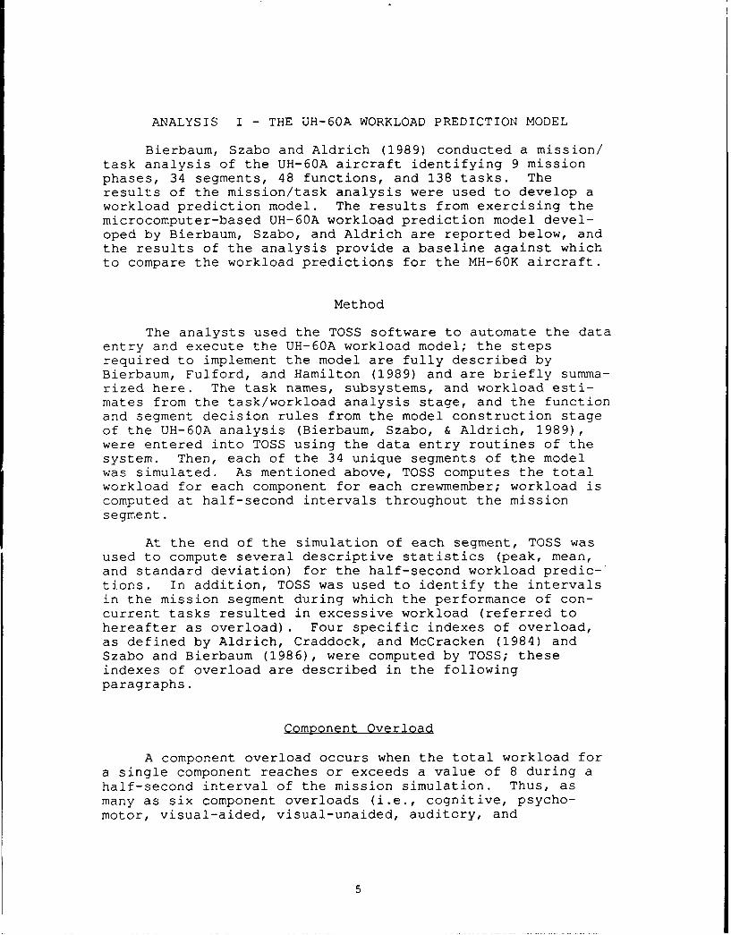
8. Example of an MH-60K Segment SummaryWorksheet ...... .................. .. 28
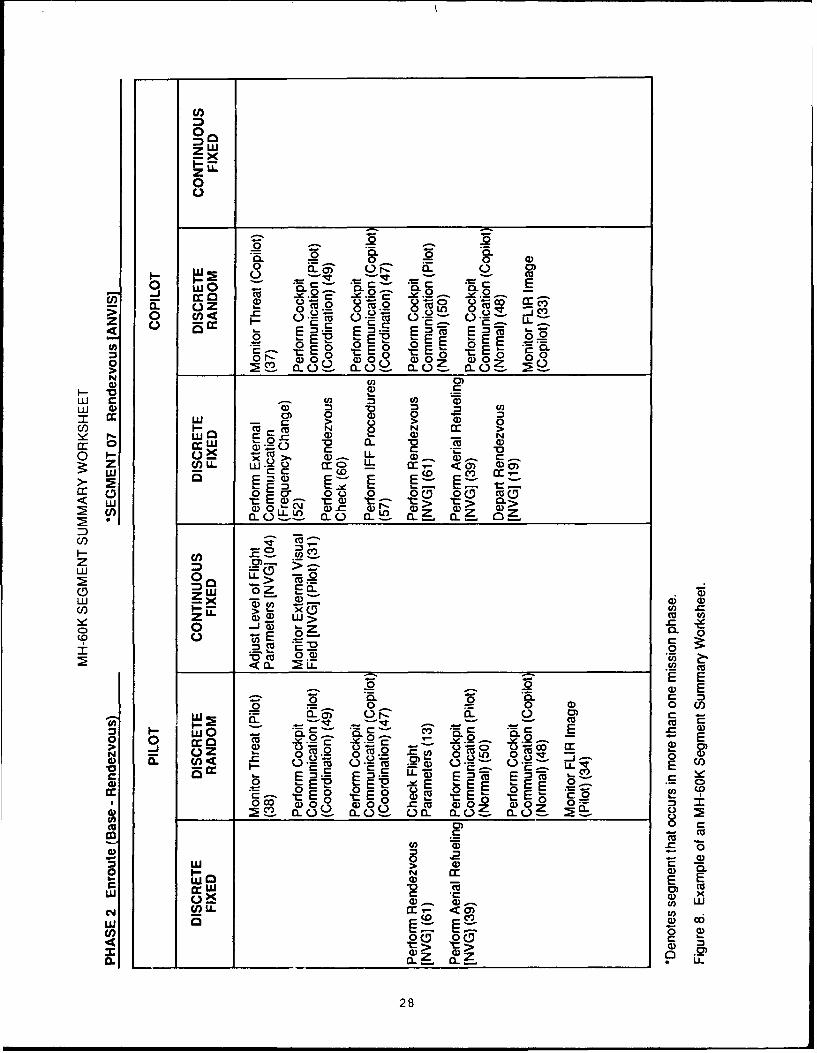
9. Example of an MH-60K Segment DecisionRules Worksheet .... ............... .29
10. Pilot's average component workload bysegment ....... ................... .. 36
11. Copilot's average component workload bysegment ....... ................... .. 37
12. Comparison of MH-60K and UH-60A predictedOW by segment for the pilot (upper) andcopilot (lower) ..... ............... .. 39
xiv

Task Analysis and Workload Prediction Model of theMH-60K Mission and a Comparison with UH-60A
Workload Predictions
INTRODUCTION
The Special Opeiations Forces (SOF) Aviation ProjectOffice at the Army Aviation Systems Command (AVSCOM) has beentasked to modify existing UH-60A aircraft for SOF missions.The aircraft, designated the MH-60K, will be modified byreplacing present instrumentation with a fully integratedcockpit featuring four multifunction displays (MFDs) . Themodifications include:
* terrain avoidance/terrain following radar,
* forward-looking infrared (FLIR) capability,
• flight symbology on the Aviator's Night Vision ImagingSystem (ANVIS),
" improved navigation capability, including global posi-tion system (GPS) and continuous present positiondisplay,
" improved flight control with all axes coupled to themission computer,
" map display on the MFDs, and
" air-to-air refueling capability with automatic fuelconsumption display.
The modifications being prepared for the MH-60K aircraftare designed to increase operational effectiveness and toreduce operator workload during SOF missions. The increasedmission capabilities of the MH-60K aircraft have dramaticallyincreased the amount of display information available to theoperators and may increase operator workload by placing addi-tional demands on the cognitive resources of the crewmembers.Although many tasks performed by the operators in the UH-60Ahave been automated in the MH-60K aircraft, technology thatreduces an operator's need to maintain physical control ofsystem functions often increases the operator's role as amonitor. Thus, in some instances, automation may simplychange the nature of the task without decreasing operatorworkload.
A mission/task/workload analysis was needed to assessthe impact of the MH-60K aircraft modifications and the SOFmission on crew workload. The SOF Aviation Project Officerequested that the Army Research Institute Aviation Researchand Development Activity (ARIARDA) use the Task Analysis/Workload (TAWL) prediction methodology to (a) conduct amission/task analysis for the UH-60A and MH-60K aircraft, (b)produce workload predictions for the UH-60A and MH-60Kaircraft, and (c) compare the workload in the MH-60K withworkload in the UH-60A.

The TAWL Methodology
Under contract to ARIARDA, Anacapa Sciences personneldeveloped TAWL for predicting operator workload. Initially,the methodology was used to address design issues for theArmy's Light Helicopter Family (LHX) aircraft (Aldrich,Craddock, & McCracken, 1984; McCracken & Aldrich, 1984). Themethodology was later refined and used to develop a model ofoperator workload for the AH-64A aircraft (Szabo & Bierbaum,1986). Bierbaum, Fulford, and Hamilton (1989) provided acomplete description of the TAWL prediction methodology andits computer support. The remainder of this subsectionpresents an overview of the latest version of the TAWLmethodology.
A TAWL workload prediction model is developed in threestages. In the first stage, the analyst performs a task/workload analysis on the system. A prototype mission for thesystem is developed and is progressively decomposed intophases, segments, functions, and tasks. The analysis yieldsestimates of the duration of tasks, a description of thesequence of tasks, and a description of the crewmember andsubsystem associated with each task. The workload analysisis based on a multiple resources theory of human attentionand yields independent estimates of the cognitive, psycho-motor, and sensory components of workload (hereafter referredto as workload components) for each task. The theory differsfrom other multiple resource theories of attention in thenature and number of components identified in the theory.For a review of other multiple resources theories of atten-tion and their relation to workload, see Wickens (1984).
The TAWL methodology treats each of the workload compo-nents independently for two reasons. First, although inter-actions between the components probably occur, adequatedefinitions of the nature of the interactions do not exist.Second, the additional information that results from treatingworkload components individually is useful for determiningappropriate ways to reduce workload or to redistribute work-load among the crewmembers, subsystems, or components. Forexample, a designer could decide whether additional informa-tion should be presented visually or aurally by determiningwhich component had the least amount of workload.
The workload analysis is based upon subjective estimatesof operator workload rather than estimates derived throughexperimentation. The research analysts and MH-60 subjectmatter experts (SMEs) generated workloa stimates by usingequal-interval, verbally anchored rating scales; the scalevalues range from 1.0 to 7.0. This approach avoids the
2

expense in time, money, and manpower required to deriveempirical measures of workload.
In the second stage of the TAWL methodology, the analystdevelops a model of each crewmember's actions by recombiningtasks to simulate the behavior of the crewmembers during eachsegment of the mission. Function decision rules are devel-oped that describe the sequencing of tasks in functions;segment decision rules are developed that describe thesequencing of functions in segments. It is assumed that thesegments can be combined to model the crewmember's behaviorfor individual phases and for the entire mission.
In the third stage of the TAWL methodology, the analystexecutes the model to simulate the crewmembers' actionsduring the operation of the system. The TAWL Operator Simu-lation System (TOSS) computer software performs the simula-tion and produces estimates of each crewmember's cognitive,psychomotor, and sensory workload for each half-second of themission. The estimates of workload for each component aregenerated by summing the workload for that component acrossall tasks that the crewmember performs concurrently duringeach half-second of the mission. For example, during aspecific half-second interval, the pilot performs the tasks:Control Attitude, Check External Scene, and Transmit Communi-cation. The cognitive workload for the three tasks duringthat interval is 1.0, 1.0, and 5.3, respectively. Thus, theestimate of cognitive workload for the pilot during thatinterval is 7.3.
A criterion that represents an estimate of the overloadthreshold is used during execution of the model to produceestimates of the amount of time during the mission that eachcrewmember experiences an overload condition.
Using the TAWL prediction methodology, an analyst candevelop a model of a system and use the model's output todetermine:
" the absolute and relative workload of the crewmember,
* the time intervals (in half-second minimum intervals)during which crewmembers experience high workload, and
* the components for which crewmembers experience highworkload.
The information yielded by the TAWL methodology mayenable system designers to reduce workload or to redistributeworkload over time, crewmembers, or components. Designersalso may use the information to identify design alternativesthat result in lower workload.
3

In addition to the uses described above, the methodology.yields mission time lines and task listings (at half-secondintervals) that can be used to develop the system's manningand training requirements.
Overview
The research described in this report is designed toaddress the issues of workload in the MH-60K aircraft. Toplace the MH-60K workload predictions in perspective relativeto other similar aircraft, a baseline workload predictionmodel was prepared for the UH-60A aircraft. The task/workload analysis and model construction phases of the UH-60Abaseline model were described in a report by Bierbaum, Szabo,and Aldrich (1989). Thus, the present research has thefollowing objectives:
• exercise the UH-60A model to produce estimates ofoperator workload during the UH-60A combat mission,
" produce an analysis of the tasks that must be per-formed to accomplish the MH-60K combat mission,
" develop a computer model to predict MH-60K operatorworkload,
" exercise the MH-60K model to produce estimates ofoperator workload during the MH-60K mission, and
• compare the MH-60K operator workload predictions withthe UH-60A baseline operator workload predictions.
The research is reported in three volumes. Volume Isummarizes the methods and results of the research. VolumeII comprises Appendixes A through G, which present the work-load predictions of the UH-60A baseline model and contain thedata produced during the task/workload analysis of the MH-60Kaircraft. Volume III comprises Appendixes H through N, whichcontain the data produced during the construction of the MH-60K model, the workload predictions of the MH-60K model, anda comparison list of the segment and function names in theUH-60A and the MH-60K models.
4
ANALYSIS I - THE UH-60A WORKLOAD PREDICTION MODEL
Bierbaum, Szabo and Aldrich (1989) conducted a mission/task analysis of the UH-60A aircraft identifying 9 missionphases, 34 segments, 48 functions, and 138 tasks. Theresults of the mission/task analysis were used to develop aworkload prediction model. The results from exercising themicrocomputer-based UH-60A workload prediction model devel-oped by Bierbaum, Szabo, and Aldrich are reported below, andthe results of the analysis provide a baseline against whichto compare the workload predictions for the MH-60K aircraft.
Method
The analysts used the TOSS software to automate the dataentry and execute the UH-60A workload model; the stepsrequired to implement the model are fully described byBierbaum, Fulford, and Hamilton (1989) and are briefly summa-rized here. The task names, subsystems, and workload esti-mates from the task/workload analysis stage, and the functionand segment decision rules from the model construction stageof the UH-60A analysis (Bierbaum, Szabo, & Aldrich, 1989),were entered into TOSS using the data entry routines of thesystem. Then, each of the 34 unique segments of the modelwas simulated. As mentioned above, TOSS computes the totalworkload for each component for each crewmember; workload iscomputed at half-second intervals throughout the missionsegment.
At the end of the simulation of each segment, TOSS wasused to compute several descriptive statistics (peak, mean,and standard deviation) for the half-second workload predic-tions. In addition, TOSS was used to identify the intervalsin the mission segment during which the performance of con-current tasks resulted in excessive workload (referred tohereafter as overload). Four specific indexes of overload,as defined by Aldrich, Craddock, and McCracken (1984) andSzabo and Bierbaum (1986), were computed by TOSS; theseindexes of overload are described in the followingparagraphs.
Component Overload
A component overload occurs when the total workload fora single component reaches or exceeds a value of 8 during ahalf-second interval of the mission simulation. Thus, asmany as six component overloads (i.e., cognitive, psycho-motor, visual-aided, visual-unaided, auditory, and
5

kinesthetic) may occur for each half-second interval on themission timeline. The value 8 was chosen as the overloadthreshold because it exceeds the maximum value on the 7-pointworkload component rating scales.
Overload Condition
An overload condition exists when at least one componentoverload occurs. An overload condition is a variable-lengthperiod that contains at least one component overload. A newoverload condition is counted whenever the tasks contributingto a component overload change. Overload conditions identifythe unique conditions within a mission segment associatedwith a component overload.
Overload Density
Overload density is the percentage of time during amission segment that a component overload is present. It iscalculated by dividing the number of half-second intervals ina mission segment that contain component overloads by thetotal number of half-second intervals in the segment.
Subsystem Overload
Subsystem overload is the number of half-second intervalsthat a subsystem is associated with a component overload. Allsubsystems associated with the tasks being performed during acomponent overload are assigned an overload. The tallies ofsubsystem overloads identify the subsystems that areassociated with high workload.
Overall Workload
Iavecchia, Linton, Bittner, and Byers (1989) conductedresearch to determine the validity of the UH-60A workloadprediction model. The researchers obtained subjective rat-ings of overall workload (OW) for pilots performing a typicalUH-60A mission in the UH-60A flight simulator. During mis-sion segments, pilots provided ratings of their workloadusing a continuous scale that ranged from 0 to 100, with theextreme values verbally anchored to "Very Low Workload" and"Very High Workload." To establish the validity of the UH-60A workload prediction model, the observed OW measures werecompared to the workload predictions produced by the model.
6

However, the UH-60A workload prediction model produces pre-dictions of workload independently for six workload compo-nents and does not produce a single overall estimate ofworkload. To compare crew OW with TAWL predictions requiredthat they combine the predictions across components and timeto produce a single workload index comparable to OW. Theiesearchers assumed simple additivity and summed the UH-60Apredictions across time and components to generate an esti-mate of OW for each crewmember during each segment. Thecorrelations between the subjective OW observed by Iavecchiaet al. and the OW predicted by the UH-60A model were high(. = .82 to .95).
During the present workload analysis of the UH-60A, TOSSwas used to implement a regression equation derived from thedata reported by Iavecchia et al. (1989), to scale the OWpredicted by TAWL into the 0-100 range used for OW. For allmission segments described in this report, TOSS computed thepredicted OW using the following equation:
OW AUD + KIN + VIS + NVG + COG + P S Y 41 + 7.26.0 x 1
where AUD, KIN, VIS, NVG, COG, and PSY represent the meanauditory, kinesthetic, visual-unaided, visual-aided, cogni-tive, and psychomotor workload for the segment.
Several points should be made about this regressionequation. First, if the measure of model validity is in thedegree of correlation between OW and UH-60A component aver-ages, then scaling is unnecessary. The equation is onlyuseful in generating predictions of aviator's OW from TAWLworkload predictions. Second, the relationship between the7-poiriL scales used to generate the UH-60A predictions andthe 0 to 100 OW scale is unclear. The 7-point scales weredeveloped to estimate the workload of a single component fora single task over a half-second time period, whereas the OWscale was developed as an estimate of the workload for allcomponents over a much greater period of time. Furthermore,the 7-point scales have a nominal overload threshold (thepoint at which task performance is expected to degrade) of 8,whereas it is unclear where this point is on the OW scale.If the 0 to 100 scale is taken to represent the extent ofworkload experience and if that experience includes situa-tions of task degradation due to high workload, then theoverload point on the OW scale has not been logically orempirically determined..

Third, this regression equation, generated from empiri-cal results, differs from any simple scaling equation gener-ated logically. For example, the slope of the equation thatscaled a 7-point scale to a 100-point scale would be 14.3,similar to the slope of 14.5 in the equation. However, theintercept of the 7-point to a 100-point equation would be0.0, whereas the intercept of the OW regression equation is7.5. Thus, if all TAWL component workload predictions were0.0, the equation would predict pilot OW to be 7.5.
Regardless of the possible inaccuracies of the empiri-cally derived OW regression equation, it is currently theonly link between the workload predictions generated by aTAWL prediction model and an overall subjective measure ofworkload. Therefore, it has been used to compute an overallestimate of aviator workload in the analyses of the UH-60A,the MH-60K, and their comparison.
Results
Workload prediction graphs for the pilot and copilotwere produced for each of the 34 UH-60A mission segments.The graphs present the total workload of each component forall tasks the crewmember performs during each half-second ofthe mission segment. An example of a pilot segment workloadprediction graph is presented in Figure 1. Figure 1 showsestimated workload for the pilot on each component during theBefore Takeoff (External Load) [NVG] segment of the mission.A brief description of the graph for each component inFigure 1 follows.
Workload associated with random cockpit communicationcan be seen in the auditory graph as a pair of closely spacedpeaks of workload. The higher peak occurs when the pilotreceives the communication and the lower peak occurs when thepilot transmits. The kinesthetic graph initially indicateslow workload while the aircraft is on the ground andincreased workload at the time (110 seconds elapsed time) thepilot initiates a hover to pick up the external load. TheNVG (visual-aided) graph shows that the pilot experiencesrelatively low NVG workload until he begins to hover theaircraft. At that time (110 sec.), the NVG workloadincreases as the pilot shifts attention to the ground guidefor directions over the sling load. The interruption in theNVG workload shortly after 100 seconds is the result of thepilot checking the instruments before picking the aircraft upto a hover. This instrument check is also indicated by theincrease in unaided visual workload at the same elapsed timeon the visual graph. The completion of external load hook-upcan be seen when the NVG workload decreases between 400 and
8

8
4
0-
8
4.C
0
c4L
> 4
0 0[ -------- I I
8
4-
0,0.
0 8 0 10 10 20 20 30 5 0 5 0
-00
0E
-
a_0 50 100 150 200 250 300 350 -400 450 500Time (Sec)
Figure 1. Example of a pilot segment workload predictiongraph.
9

450 seconds of elapsed time. At this time, tne pilot ceasesobserving the ground guide and returns to monitoring outsidethe aircraft. The cognitive workload is low when the pilotis simply monitoring outside the aircraft but increases whenthe pilot begins to hover the aircraft. In addition, cogni-tive workload associated with cockpit communication can beseen as a pair of peaks each time communication occurs.Finally, the psychomotor graph indicates the workload asso-ciated with moving the flight controls while hovering and theswitch activation required to communicate. The diamond atthe end of each graph indicates the mean component workloadfor the entire segment. Appendix A presents grap' of pilotworkload for each of the 34 mission segments. Each pagedisplays the pilot workload for one segment using 6 graphs,one for each workload component. Appendix B presents graphsof copilot workload for each of the mission segments.
The UH-60A workload model predictions for the pilot andcopilot are summarized in Tables 1 and 2, respectively. Thetables show, for each of the 34 segments, the number of over-load conditions (OC), the average workload for each of the 6components, and the predicted OW.
The data contained in the tables indicate the following:
" The only overload condition observed during themission occurred during the NOE and the contour flightsegments when a threat was present (overload condi-tions occurred for both the pilot and copilot duringthese segments).
" The pilot's average kinesthetic and psychomotor work
load is higher during flight segments.
• The pilot's average OW is highest in the Takeoff(External Load) segment.
" The copilot's average cognitive workload is higherwhen performing navigation during en route flightsegments.
" The average copilot's OW is highest in the NOE Flight(Mission Change) segment.
" Both crewmembers' average OW is higher during flight
segments.
" Proficient crewmembers can perform the UH-60A missionswithout encountering an overload condition, exceptwhen being engaged by a threat.
10

Table 1
Pilot Workload for the UH-60A Model by Segment
Segment OC AUD KIN VIS NVG COG PSY Ow
11: Before Takeoff (Assembly Area) 0 1.0 1.4 1.3 0.0 2.2 0.4 23.6
02: Takeoff 0 2.7 7.0 2.0 0.0 3.6 3.2 52.1
03: Takeoff NVG 0 1.5 7.0 0.3 1.1 2.8 3.0 45.1
4: Contour Flight 0 1.3 7.0 1.9 0.0 3.2 2.9 46.8
05: Contour Flignt [NVG 0 1.3 7.0 0.4 0.9 3.2 2.9 45.1
6: Contour Flight (Threat) 6 1.3 7.0 2.0 0.0 3.3 2.9 41.2
07: ucnto:r Flight (Threat) 'N".C2 1.3 7.0 0.4 1.0 3.2 2.9 4.4
C8: Contour Flight (Mission Change) 0 1.3 7.0 1.9 0.0 3.2 2.9 42.5
09: Contor F (Xissicn C'nange) 0 1.3 7.0 0.4 0.9 3.2 2.9 45."
: Ao roach 0 1.3 7.0 1.2 0.0 2.9 2.9 44.
.1: Aoroach IVO 0 1.3 7.0 0.2 0.9 2.9 2.9 43.3
-2: L an n C 2.1 6.6 2.0 0.0 3.0 2.9 47 -
13: Land~ng NV' 0 1.2 6.8 0.0 '.4 2.6 .8 42.9
.4: Before Takeoff (Internal Load) 0 1.7 1.0 1.0 0 0 2.9 0.4 23 9
.5: Before Takeoff (External Load) 0 1.1 5.1 2.8 0.0 4.1 2.' 44 .
.C: Before Takeoff (External Load) 0 0.9 5.5 0.I 3.6 4.0 2.2 46.ENVG "
: Takeoff (External) 0 3.5 7.0 2.2 0.0 4.9 3.4 57.9
-8: Tae ff (Exe rna ) [NVG] 0 2.7 7.0 0.9 0.7 3.5 3.2 5 .
.: NA Fl~gnt 0 1.3 7.0 1.9 0.0 3.2 2.9 4E.
2'-: NOE Flight [NVG1
0 1.3 7.0 0.4 0.9 3.2 2.9 45.2
2 no ,7n r. (Threat) 6 1.3 7.0 2.1 0.0 3.3 2.9 47.3
22: NOE F light (Threat) NVG] 2 1.3 7.0 0.4 1.0 3.3 2.9 45.7
23 : NOE Flight (Mission Change) 0 0.8 7.0 2.0 0.0 2.7 2.8 44.2
24: N0E Flight (Mission Change) 0 0.8 7.0 0.4 0.9 2.7 2.8 42.5
2 5: Approach (LZ) 0 1.3 7.0 1.2 0.0 2.9 2.9 44.0
26: Anproacn (LZ) [NVG] 0 1.3 7.0 0.2 0.9 2.9 2.9 44.0
27: L.anding kLZ, Tnternal Load) 0 1.2 6.5 2.1 0.0 2.6 2.7 43.6
28: Landing (LZ, Internal Lc(ad) 0 1.1 6.6 0.1 1.4 2.5 2.7 41.4
[NVG!
29: Landing (LZ, External Load) 0 1.3 6.5 2.2 0.0 2.8 2.8 44.6
30: Landing (LZ, External Load) 0 1.2 6.6 0.1 1.4 2.7 2.8 42.5
[NVG]
31: Before Takeoff (LZ) 0 2.0 1.0 0.0 1.0 3.2 0.4 25.2
32: FAR? Procedures 0 0.8 3.1 1.4 0.0 2.2 I.1 28.2
13: FAR? Procedures [NVG] 0 0.7 3.8 0.2 0.9 2.2 1.4 29.1
34: Before Takeoff (FARP) 0 2.8 1.0 1.0 0.0 3.1 0.7 28.1
Noe. The fo.iowing abbreviations are used as rolumn headings in Table 1: OCC Overload
Condition, AJD Auditory, KIN = Kinesthetic, VIS = Visual-unaided, NVG = Visual-aided, COS -
.gnltive, PSY ' Psychomotor, OW = Overall Workload.
1I

Table 2
Copilot Workload for the UH-60A Model by Segment
Se o-en Oc AUD KIN VIS NVG COO PSY O
C : Before Takeoff (Assembly Area) 0 1.1 0.1 4.0 0.0 2.8 3.5 34.9
2: Tak-off 0 2.7 0.2 1.6 0.0 3.1 C.4 26.6
13: TakeoffNVG 0 1.5 0.1 0.5 1.2 2.3 0.2 21.3
" 1.3 0.1 4.8 0.0 6.1 2.6 42.9
0NVG7 '.5 0.i 3.7 0.8 2.4 42.1
En'gor (Threat) 6 1.3 0.1 4.7 0.c 5.9 2.4 42.1
Fliqht (Threat) [NVG' 3 1.3 0.i 3.5 1.1 6.0 2.1 41.4-- c~ . lqh (Ysson: Change) 0 1.5 0.1 4.4 0.0 . .C 4.
(Miss Charge 1 1.5 C.1 3.8 C.4 ..
n . " 1.6 0.1 0 3 0.8 .2.
2.4 1.2 0 .6
0 1.4 C.1 0.2 L 2: a<e tnternal Load) 4 2.0 0.1 4.3
e ere akeoff (Exte-ai Load) 0 1.2 .1 2.6 . 4": eoe. ... (External Load) 0 1.0 0. 1.5 17 . Z; 2.
e ,, e d C
e e (xe r a.) 3.5 0.3 2.2 2. 2 3 . E
: e ( x erna-) " 0 2.7 0.
1.3 . 4 8 .: .. 3 .1 4 .4 1.4
N n rear) 6 1.5 .4.6
reat) NVG 2 1.5 C. 4 .2 0.4 E.2 2 42.
.: ? .Y. isslon Chanae) 0 1.0 01 5 0.0 . .
4ont (Mission Change) 0 01 4 0.3 8.1 3. 4
aA on. (n C ) 0 1.3 0.1 1.3 0..
zE: Anprcicr. (LZ) 'NVSl 0 1.3 0.1 0.4 0. .9 19 0.2 18.6
g_,a n1 ng (LZ, internal Load) 0 1.2 0.1 1.5 0.0 I C.
-8 a nor,(g (Z, internal Lodd) 0 1.1 0.1 0.4 . ".9 0.3 19.4
2 ia n ,g (LZ, External Load) 0 1.3 0.1 1.5 0.0 1.8 C.3 9.2
O andig ('Z, External Load) 0 1.2 0.1 0.4 1.4 2 .. 2 .0
j. ,.'nore Takeoff (-Z) 0 2.0 0.1 2 o CC 2. .R 2>.
,2: r e res c 0.8 I.1 0.5 0.0 1.1 1.1 13.2
-- 6A-rotc" NWrs MVI 0 0.7 0.1 0. r 0. . .. 7.1 13.C
,;: :e TaIeoff )ARP) 3.7 0.2 2.6 0 2.4 1.2 31.8
.. -r. wn; abbrevlat ions are ,s--d as coluron headings n 7an- . 7 a. dver.2ad
Al - AKo:onry, 812 8:nest net i7, V.E - V4soal-naided, N'Y C V. -,c
P S Y P SyV Ct orC,:;W -verall Workloao.
12

ANALYSIS II - THE MH-60K WORKLOAD PREDICTION MODEL
The MH-60K workload prediction model was developed withthe same procedures as the UH-60A model (Bierbaum, Szabo, &Aldrich, 1989). The following section includes a fulldescription of the TAWL methodology used for the MH-60K forthe benefit of the reader not in possession of the previousreport. The section also includes the results of exercisingthe TOSS software in the analysis of workload for the MH-60Kaircraft and a comparison of MH-60K and UH-60A operatorworkload predictions.
Method
Mission/Task/Workload Analysis
The mission tasks and workload for both the pilot andcopilot were analyzed. The analytic tasks are listed belowin the order in which they were performed:
• develop a composite mission scenario," divide mission into phases,• divide mission phases into segments,• identify functions in the mission segment,* identify tasks for each function, and• analyze individual tasks.
A diagram of the taxonomy used in the top-down analysis ofthe MH-60K mission is shown in Figure 2. Each of theanalytic steps is described in the following subsections.
Develop a Composite Mission Scenario
The first step in conducting the MH-60K mission/task/workload analysis was to develop a composite mission sce-nario. A composite mission is a combination of the uniqueoperations present in several typicai !.!H-60K missionm. Acomposite mission scenario was developed for the MH-60K fromunique mission profiles that differed in the following ways:
" the mode of flight (en route, contour, NOE)," the presence of a threat during flight, and• the receipt of mission changes during flight.
Information from three sources was used to develop thescenario: (a) the International Business Machines IntegratedAvionics Subsystem (IAS) technical proposal, (b) the IAScontrol layer formats, and (c) interviews with 160th SOAGUH-60A SMEs. The researchers made thzee assumptions indeveloping the mission scenario. First, the prototypical
13

MISSION
PHASE
SEGMENT
FUNCTION
TASK
SUSSE WORKLOAD DURATIONEQUIPMENT
VI SUAL - VISUAL-AUIOYKNSHT
AIDED FUNAIDED ADTR IETEI
Figure 2. Diagram of the taxonomy used in the top-downanalysis of the MH-60K mission.
mission fL: the MH-60K aircraft is to support special opera-tions by transporting personnel and Lnternal cargo at night.Second, the pilot's primary role is to fly the aircraft andthe copilot's primary role is to assist the pilot and toperform navigation functions. Third, the mission is flownunder optimal conditions (i.e., full moon with no degrada-tions due to weather or equipment). By assuming optimalconditions for the mission, the most conservative estimatesof workload are produced. That is, if excessive workload
14

occurs during optimal conditions, excessive workload alsowould be expected during degraded conditions.
The resultant MH-60K mission is depicted schematicallyin Figure 3. Dashed rectangles represent mission phases;solid rectangles represent mission segments. The MH-60Kmission begins at a base where the crew performs preflightand departure operations. The pilot then flies contourflight from the base to a rendezvous point where air-to-airrefueling operations are performed. After completing therefueling operations, the pilot flies NOE to the landing zone(LZ), where combat troops are inserted or cargo is delivered.After comple: ting the troop and/or cargo delivery, the pilotflies NOE back to a rendezvous point for air-to-air refuel-ing. Upon completion of the second refueling operation, thepilot flies contour back to the base, where postflightactivities are conducted.
Although the activities and conditions encountered onany given mission may differ from those described above, thephases of the mission adopted for this research are represen-tative of tactical missions for the MH-60K aircraft. Fur-thermore, the scenario developed for the MH-60K analysis ishighly similar to the scenario and conditions used to developthe UH-60A workload prediction model (Bierbaum, Szabo, &Aldrich, 1989). The close correspondence between the UH-60Amission and the MH-60K mission facilitated the comparison ofworkload predictions for the UH-60A and MH-60K aircraft.
Divide Mission Into Phases
Once the mission was identified, it was divided intotemporally discrete, uninterruptible, and nonrepeating divi-sions called phases. A phase is defined as a required, logi-cal part of a mission that may be accomplished in severalways. Phases must be performed sequentially (i.e., phasescannot be performed concurrently) and must be contiguous.All portions of the mission are encompassed under one of themission phases and every phase must be performed to accom-plish the mission. Thus, the mission consists of a sequenceof phases placed end to end (see Figure 3).
Divide Mission Phases Into Segments
The mission phases were divided into temporallydiscrete, uninterruptible parts called segments. A segmentrepresents a particular method of accomplishing a part of aphase. Segments must be sequential to other segments and
15

* CONFIGURE SYSTEMS
* FOR MISSION
BEFORE TAKEOFF PHASE 1:.... .....o~................. S I
(BASE/INTERNAL LOAD) DEPARTURE (BASE)
T.......... ................... }::: 2: :2 ......................i
(NO UPDATE) (A S] (UPDATE) [ANVIS] PNASE 2:.... . ENROUTE(BASE-RENDEZVOUS)
e PHASE 3:
N V(RENDEZVOUS-LZ)
*LANDING (LZ/INTERNAL
OA)[ANVIS ]................ = = .. = = 7............N * BEFORE TAKEOFFGH
* * ]PHASE 4:
C L- - - - -. . . . . . ENROUTE
* (LZ-RENDEZVOUS)
* HOENIGH ( ROTEA
I LADG) [ANVIS]
* B ERENDEZVOUS
[ANVIS]
S CONTOUR FLIGHT
CHUPAGE) JANVIS]
' 1 So APPROACH *PAE5
SVS (RENDEZVOUS-BASE)............. . . . .
Noe The following abbreviations are used in Figure 3:ANVIS = Aviator's Night Vision Imaging System; ASE = Aircraft
Survivability Equipment; LZ = Landing Zone.
Figure 3. Schematic diagram of the MH-60K composite missionscenario.
16

must be contiguous. Different segments may represent differ-ent methods for accomplishing the same portion of a phase;thus, every segment identified for a phase may not be neededto complete that phase. A segment defined for one phase mayappear in one or more other phases. Takeoff [ANVISI is anexample of a segment that appears in more than one missionphase.
Identify Functions in the Mission Segments
The next step was to identify all interruptible parts ofsegments, which are called functions. A function is definedas a collection of a crewmember's actions that are necessaryto carry out a single logical activity. The same functionmay be performed in different segments. Functions can beperformed concurrently or sequentially. Examples of func-tions are: Establish Hover, Monitor Threat, Perform Navi-gation, and Check Flight Parameters. For each functionidentified during mission decomposition, a Function AnalysisWorksheet was developed to organize the information gainedfrom the analysis. Figure 4 presents an example of aFunction Analysis Worksheet.
Identify Tasks for Each Function
The lowest level of mission decomposition is the task.Tasks are defined as the uninterruptible crew activities thatare required for the successful completion of a function.Tasks can be performed concurrently or sequentially. Eachtask identified for a particular function was listed on theFunction Analysis Worksheet for that function. Tasks weredescribed by verbs and objects, which were listed in thefirst two columns of the worksheet. The verb described thecrewmember's action; the object described the recipient ofthe action. Examples of verbs include check, set, position,monitor, and release; examples of objects include switches,knobs, helmets, and maps.
Analyze Individual Tasks
Each task was analyzed separately to produce the infor-mation required to develop the workload prediction model.For each task, the analysts identified the crewmember whoperformed the task, the subsystem used to perform the task,the workload imposed by the task, and the duration of thetask. The task data were entered on a Function AnalysisWorksheet prepared for each function. Figure 4 presents the
17

CC
9 a oSo) 4 Uc
0U) La U) U
- zE 0
'F
4U) U) 0>0
ww
00
o 0 .jC4c4C
* 4'
0 L 0.. 0I0 0L.0. 0.0. C
zz 00
cc 00 1
C. CS 8 (38(Ci) U) 2U i )
0 a) D-1 8 1 > C)
z cc~ .-8%
z
0 01 Zz Sj 3 - S
w 0 o 0C
U)
aLL a LL c X LLLLU) (a
y CY 0- 0r
(0
U) .
Icc 000z z CL
0 I00
0o (0. (a
U) V) 8> M CL M. M. LLL)
I- LI. U. I. u18

data for each of the tasks identified in the mission functionentitled "Perform IFF Procedures." Figure 4 is referred toin the following paragraphs, which describe how the task datawere derived, and in the subsequent subsection, whichdescribes the procedures used to develop the workload predic-tion model.
The verbs and objects defining the tasks a.e presentedin Columns 1 and 2, respectively, of the Function AnalysisWorksheet. The remaining columns present data on each of thefollowing:
" crewmember(s) performing the task," task identifiers," the subsystem(s) on which the task is performed,* the estimated workload imposed by the task, and* the task duration.
The procedures used to derive these data are described below.
Identify crewmember(s). Once the tasks for each func-tion were identified, the analyses identified the crewmembersperforming the task. Specifically, each task within a givenfunction was assigned to the pilot, copilot, or both crew-members. SMEs made the assignments. In general, all flightcontrol tasks were assigned to the pilot; all navigation andsupport tasks were assigned to the copilot.
On the Function Analysis Worksheets, tasks performed bythe pilot were indicated by the letter "P" in the thirdcolumn; similarly, tasks performed by the copilot wereindicated by the letter "C." For example, Column 3 in Figure4 indicates that the copilot performs the task "Check IFFCode."
Task identifier. Numerical identifiers for each taskare presented in Column 3 following the crewmember'sidentification.
Identify subsystem(s). The next step in the analysiswas for SMEs to identify the subsystem(s) associated witheach task. The subsystems identified for the tasks werelisted in the fourth column of the Function Analysis Work-sheets. For example, the task Check IFF Code in Figure 4 isassociated with the Control Display Unit and the Transponder.
Estimate workload. Workload, as the term is used inthis research, is defined as the total attentional demandplaced on the operators as they perform the mission tasks.Consistent with Wickens' theory of human information process-ing, human attention is viewed as a multidimensional
19

construct of limited availability (Wickens, 1984). Thisresearch methodology recognizes three different components ofattention: cognitive, psychomotor, and sensory. Thus, work-load is the demand on each of these components imposed by allthe tasks an operator is performing currently. The method-ology further assumes that each of these components is alimited resource that, when expended, will result in degradedtask performance or task shedding. Cognitive workload (COG)refers to the level of information processing required of theoperator; psychomotor workload (PSY) refers to the complexityof the operator's behavioral responses; sensory workloadrefers to the complexity of the visual-unaided (VIS), visual-aided (NVG), auditory (AUD), and/or kinesthetic (KIN) stimulito which an operator must attend.
To derive a workload estimate for each task, theanalysts first identified the specific workload components(i.e., cognitive, psychomotor, auditory, visual-unaided,visual-aided, and kinesthetic) that applied to each task.Then, they wrote a short verbal description of the atten-tional demands imposed on each component. Often the perfor-mance of a task imposed demands on several components. Forexample, consider the task of setting a switch in the cock-pit. First, cognitive attention is required to decide that anew switch position is necessary. Next, psychomotor atten-tion is expended to move the switch. Finally, visual atten-tion may be required to ensure that the switch was placed inthe correct position. The verbal descriptions of the atten-tional demands imposed by a task are presented in Columns 5,6, and 7 of the Function Analysis Worksheets.
The analysts derived estimates of component workload bycomparing the verbal descriptions of component attentionaldentand with verbal anchors on corresponding component work-load rating scales. Table 3 presents the workload scales foreach component. Bierbaum, Szabo, and Aldrich (1989) devel-oped these 7-point, equal-interval rating scales for use inthe UH-60A workload analysis. Although all the componentworkload scales employ the same numerical values, each scaleis unique. For example, although both the NVG and thevisual-unaided tasks require the use of eyes, it is wellknown that NVG tasks require more attention than the sametasks performed unaided during daylight. The effects ofsystem modifications are compared by component. The intentis not to compare ratings of the NVG tasks with ratings ofthe visual-unaided tasks or to compare auditory tasks withpsychomotor tasks.
The analysts' task was to select the verbal anchor thatmost closely matched the written component attentional demanddescription. The rating scale value associated with the
20

Table 3
Workload Component Scales
Scale VerbalValue Anchors
1.0 Automatic (Simple Association)1.2 Alternative Selection3.7 Sign/Signal Recognition4.6 Evaluation/Judgment (Consider Single Aspect)5.3 Encoding/Decoding, Recall6.8 Evaluation/Judgment (Consider Several Aspects)7.0 Estimation, Calculation, Conversion
1.0 Speech2.2 Discrete Actuation (Button, Toggle, Trigger)2.6 Continuous Adjustive (Flight Control, Sensor Control)4.6 Manipulative5.8 Discrete Adjustive (Rotary, Ve.iL..dl Thumbwheei, Lever
Position)6.5 Symbolic Production (Writing)7.0 Serial Discrete Manipulation (Keyboard Entries)
Visual-Unaided (Naked Eye)1.0 Visually Register/Detect (Detect Occurrence of Image)3.7 Visually Discriminate (Detect Visual Differences)4.0 Visually Inspect/Check (Discrete Inspection/Static Condition)5.0 Visually Locate/Align (Selective Orientation)5.4 Visually Track/Follow (Maintain Orientation)5.9 Visually Read (Symbol)7.0 Visually Scan/Search/1io"iLor (Continuous/Serial Inspection,
Multiple Conditions)
Visual-Aided (Night Vision Goggles rNVG1)1.0 Visually Register/Detect (Detect Occurrence of Image) With
NVG4.8 Visually Inspect/Check (Discrete Inspection/Static Condition)
With NVG5.0 Visually Discriminate (Detect Visual Differences) With NVG5.6 Visually Locate/Align (Selective Orientation) With NVG6.4 Vi ally Track/Follow (Maintain Orientation) With NVG7.0 Vis'ally Scan/Search/Monitor (Continuous/Serial Inspection,
Multiple Conditions) With NVG
Continued on the next page
21

Table 3
Workload Component Scales (Continued)
Scale VerbalValue Anchors
Auditr1.0 Detect/Register Sound (Detect Occurrence of Sound)2.0 Orient to Sound (General Orientation/Attention)4.2 Orient to Sound (Selective Orientation/Attention)4.3 Verify Auditory Feedback (Detect Occurrence of
Anticipated Sound)4.9 Interpret Semantic Content (Speech)6.6 Discriminate Sound Characteristics (Detect Auditory
Differences)7.0 Interpret Sound Patterns (Pulse Rates, Etc.)
Kinesthetic1.0 Detect Discrete Activation of Switch (Toggle,
Trigger, Button)4.0 Detect Preset Position or Status of Object4.8 Detect Discrete Adjustment of Switch (Discrete
Rotary or Discrete Lever Position)5.5 Detect Serial Movements (Keyboard Entries)6.1 Detect Kinesthetic Cues Conflicting With Visual Cues6.7 Detect Continuous Adjustment of Switches (Rotary
Rheostat, Thumbwheel)7.0 Detect Continuous Adjustment of Controls
verbal anchor selected was assigned to represent the level ofworkload for that component of the task.
The numerical ratings of the cognitive, psychomotor, andsensory workload associated with the tasks were recorded onthe Function Analysis Worksheet immediately below the corre-sponding verbal descriptions of component attentional demand.For example, the numerical rating of the visual-unaidedworkload associated with the task "Press IFF Key" in Figure 4is 3.7; the cognitive workload associated with the task is1.2; and the psychomotor workload associated with the task is2.2.1
iThe type of switch that is associated with a specific taskis a correlate of workload. Consequently, for each taskinvolving a switch, the type of switch is named in theeighth column of the Function Analysis Worksheet.
22

Estimate task duration. As the final step in themission/task/workload analysis, the analysts estimated theamount of time required to perform each task. The durationof each discrete task was recorded in Column 9 of the Func-tion Analysis Worksheet; the letter "c" was placed in Column10 when the task was judged to be a continuous task. (Mis-sion requirements determine the duration of continuoustasks.) The total time required to perform all the tasks ina function was tabulated and entered in the upper rightcorner of the Function Analysis Worksheet. The duration offunctions containing continuous tasks generally depend uponthe segments in which the functions occur. For these func-tions, the word "continuous" was entered in the upper rightcorner of the Function Analysis Worksheet.
Development of the MH-60K Workload Prediction Model
The mission/task/workload analysis described above useda top-down approach to identify the tasks that must be per-formed to meet the objectives of the MH-60K mission. Thatis, the mission was progressively decomposed into phases,segments, functions, and tasks. Tasks represented the basicunits of analysis for which estimates of workload and timewere derived. These data, in turn, make up the data baseused to develop the MH-60K workload prediction model.
A bottom-up approach was used to develop the MH-60Kworkload prediction model. The approach started with thebasic elements produced by the analysis (i.e., the tasks) andsuccessively composed the mission functions and segments.The development steps are listed below in the order in whichthey are performed:
* write decision rules,* develop computer model, and* exercise model to produce estimates of workload.
The steps performed in developing the model and producingestimates of workload are depicted schematically in Figure 5.
Write Decision Rules
The first step in developing the workload predictionmodel was to write decision rules for composing the missionsegments from the task data base. A decision rule comprisesthe information necessary to schedule a task or function inthe mission (e.g., start time and duration). First, functiondecision rules were developed for combining the tasks intofunctions. Then, segment decision rules were devel:opd to
23

MODEL CONSTRUCTION
WITE DECISION RU S DEVELOPMENT AND EXERCISE OF THE COMPUTER MODEL IN
I THE TAWL OPERATOR SIMULATION SYSTEM (TOSS)
THE MODEL
DEVELOP SEGMENT DECISION RULES E GENTER SEGMENT(COMBINE FUNCTIONS INTO SEGMENTS) DECISION RULES
(DEVELOP SEGMENT TIMELINES) ENTER_ _ _ _ _TASK ANALYSISr DATA BASE
I DEVELOP FUNCTION DECISION RULES I BASE
I NTER FUNCTION(COMBINE TASKS INTO FUNCTIONS) DECISION RULES
(DEVELOP FUNCTION TIMELINES)
TASK ANALYSIS DATA BASE
• SEGMENT LIST • WORKLOAD RATINGS• FUNCTION LIST " TI1E ESTIMATES• TASK LIST • CREWMEMBER* SUBSYSTEM IDENTIFIERS
Figure 5. Bottom-up flow diagram outlining the technicalsteps performed in developing the MH-60K workload predictionmodel.
combine the functions into segments. The function andsegment decision rules provided the information necessary toreconstruct the mission to simulate the behavior of eachcrewmember at each point on the mission timeline. Theprocedures used to develop the decision rules are describedin the following subsections.
Develop function decision rules. Function decisionrules were developed for each of the functions identified inthe mission/task/workload analysis. The decision rules weredeveloped in two stages. During the first stage, FunctionSummary Worksheets were developed. Figure 6 presents anexample of a Function Summary Worksheet. Function SummaryWorksheets describe three types of information. First, thecrewmember performing each task was indicated by placing thetask name and number in a column under the appropriate crew-member's title. Second, the approximate temporal relation-ships among the tasks were portrayed by the position of thetasks on the worksheet: tasks placed higher on the pageoccurred prior to tasks placed lower on the page. Concurrenttasks were placed side by side. Third, the task category
24

C.)C
0
z w
L-0
Lli co
wn - CDL
y 0 a: CC.) uj a 0
LL UL u- C )
cc ( U) U)CJ U
<__ M- o.Z V )::C',)
z0 (
zD -z
y 0
0 -(4) 0
C.)Z
FL. I-
E0
0
Ez 0x w
Q (fl)U. (
52

(discrete fixed, discrete random, continuous fixed, andcontinuous random) was indicated by placing the task categoryname in one of the four columns below each crewmember'stitle. For complete definitions of the task categories, seeBierbaum, Fulford, and Hamilton, (1989).
During the second stage, Function Decision Rules Work-sheets were developed from the Function Summary Worksheets.An example of a Function Decision Rules Worksheet is pre-sented in Figure 7. Function decision rules were developedthat specify the information necessary to schedule the tasks4n the function. Decision rules for discrete fixed tasks andcontinuous tasks state the start time and the duration of thetasks on the function timeline. In addition to duration, thedecision rules for discrete random tasks state the proba-bility and/or frequency of the random tasks' occurrencewithin the function.
Develop segment decision rules. The next step in thedevelopment of the model was to write the segment decisionrules. The segment decision rules comprise the informationnecessary to build the mission segments from the functions.The segments were developed in two stages: first by devel-oping Segment Summary Worksheets and then by developingSegment Decision Rules Worksheets. Figures 8 and 9 presentthe Segment Summary Worksheet and the Segment Decision RulesWorksheet for the segment, Rendezvous [ANVIS]. The function,Perform IFF Procedures, used as an example earlier in thisreport, occurs in this segment.
As illustrated in Figure 8, the Segment Summary Work-sheets list all of the functions performed by the pilot andthe copilot during a mission segment. The Segment SummaryWorksheets also identify the function category (discretefixed, discrete random, or continuous random) and theapproximate temporal arrangement of the functions withinsegments. Again, see Bierbaum, Fulford, and Hamilton (1989)for the complete definitions of the function categories. TheSegment Decision Rules Worksheets contain the decision rulesthat define the onset times for functions and their duration.
Develoip Computer Model
As with the UH-60A, the TAWL Operator Simulation System(TOSS) was utilized to implement the MH-60K workload model.The mission/task/workload analysis data entered on the Func-tion Analysis Worksheets and the function and segment deci-sion rules constitute all the information necessary for TOSSto generate workload predictions for crewmembers of the
26

02
LL.0
uzcn(
F-LU~LI
W V 'a a
UU -UJ
c~(n LL can an a
0 jeV - -3 - 0Ac
0
z
y0 c
zp u
U.U
0 0
00
Ln <
00C. 0
0(
Q --
anL
27
0
I.- [-L 0
O0 0. a)
z~ ~ 0L 0f' a O*L 0~u O ~ L
>N 00 in00 - o
E EEE 0.E0 E*2 0~~. E .O E .~ E
0) 0c 0 = a
0 3 Nz 0 0 00g. 0 b.. a) 00 NDO 0
> 0 __ m 0. Co N- ~~ ~ .(0 -cn 0 Q
a) ~E0 c~'E -~
g0 >> >u ( 0
0U _ u a - - 0
o 01 -JO -Z. r c>~ ~E = -E sE
0 00 M 0
(D 0 ED-h U- -CD a -a a
1 Q- 0 00 00CL C
0 ~~ LL -0~ .c ~' ~ O
z oco 000 > cu~ z
CD 0 CL 0
a' -0
LO a) E
*6 CL a- m00W 4 0 co
a, c0~ 'co
I.- _ _ _ _ _ _ _ _ _ _ _ _ .0. ____ __ __ __ L___ ___ __ a __0 __C ___ ___E
0 rr 3 X. C 3.9 C, x 2.28
U)
0z W
0
E E~
L- ~ 0 - r- U , 0 -
z 0 1n' r-
LLu Z LL.0 0r-.9.9 C -. 0DE
> ~L~L L C12.))LL C') LLO0IN0) c C . aC . I
LU 0 0 . N 2 M
I- P- c 0cn cc,)C~ ~ -cJ) r- C) c - (n *n Wo: 0-0- C-)Cu - c"D 7
M a' 0) Zu, 0 0~ ClEV) ~ XV LDj 0 u 5 )r 0 --
0 Ei tu w 5 DU. - ' 0CC uCC Cw C COCC 0
_____ CI)L) CLLU U- QOLLUL-LL5.. =OLLDL==L
Z (Do~c0) (n~C C - CV 0
LU~4 0 00 0 0M -r ar
LU 0 - 24
0 M. 0 c
-U 0 - -00 W Co * C - w in~
0~01 gcl0~ICO .0 . C)0 0
t:~~~~~ 0 o 6t c QQ7oUC C c c0) c
W) :3! yi~ 0 CU4)(
U- :)t: L - -L (2 0 0
aX 00.~~~~ CJLLDUL * L.
.a C4 29
MH-60K aircraft. The development of the TOSS computer modelrequires the entry of the task data and the entry of functionand segment decision rules into TOSS. These data entry tasksare depicted in the task-flow diagram shown in Figure 5 andare described in detail below.
Enter task data. The first step in developing thecomputer model was to enter the data derived during themission/task/workload analysis into TOSS. Specifically, thefollowing data were entered:
* unique mission segment names,* unique function names,• unique task names,• subsystem names and identifiers, and* the component (sensory, cognitive, and psychomotor)workload ratings for each task.
The above data items constitute the data base for thesimulation of the MH-60K mission.
Enter decision rules. The second step in developing thecomputer model was to enter into TOSS the function decisionrules and segment decision rules using the data entryroutines of the system. Specifically, the following datawere entered from the function decision rules worksheets:
* task start time,• task duration,* task crewmember, and* task frequency for random tasks.
Additionally, the following data were entered from the segment decision rules worksheets:
• function start time,* function duration,• function interrupts,* function clash pairs, and• function frequency for random functions.
These data provided the TOSS software with sufficient information to simulate the MH-60K mission and predict crew-members' workload.
Exercise Model to Produce Estimates of Workload
The analysts used TOSS to execute each of the 15 uniquemission segments in the MH-60K model to simulate operatortask performance and to produce estimates of the total work-load experienced by each crewmember during each half-secondof the mission. TOSS computes the total workload for each
30

component by summing the ratings assigned during the taskanalysis for each workload component (i.e., cognitive,psychomotor, visual-aided, visual-unaided, auditory, andkinesthetic) of each concurrent task.
Results
MH-60K Mission/Task Analysis
The mission scenario, described earlier, was dividedinto five mission phases. Preflight and postflight opera-tions were excluded from the UH-60A baseline analysis.Consequently, the analysis for the MH-60K began with depar-ture from the base and ended with return to the base. Thefive phases included in the analysis are listed below in theorder of their occurrence within the mission.
" Phase 1: Departure (Base)" Phase 2: Enroute (Base-Rendezvous)* Phase 3: Enroute (Rendezvous-LZ)" Phase 4: Enroute (LZ-Rendezvous)" Phase 5: Enroute (Rendezvous-Base)
The five mission phases were subsequently divided intomission segments. Fifteen unique segments (i.e., segmentsthat are distinctly different from any other segment) wereidentified and assigned unique two-digit identifiers. Threesegments were found to occur more than once in the mission.The number of segments identified in each of the five missionphases are as follows.
" Phase 1: Departure (Base) - 3 segments" Phase 2: Enroute (Base-Rendezvous) - 4 segments" Phase 3: Enroute (Rendezvous-LZ) - 4 segments" Phase 4: Enroute (LZ-Rendezvous) - 4 segments" Phase 5: Enroute (Rendezvous-Base) - 3 segments
The specific mission segments that compose each of the fivemission phases are listed in Appendix C.
The decomposition of segments by SMEs resulted in theidentification of a total of 71 unique functions. Each ofthe 71 functions was assigned a unique two-digit identifier.The number of functions required to compose each segmentranged from 8 to 17. Appendix D presents an alphabeticallist of the 71 functions along with their identifiers.Appendix E presents the functions that compose each of the 15mission segments.
The decomposition of the 71 functions by SMEs resultedin the identification of 230 unique tasks. The number of
31

tasks required to compose each function ranged from 1 to 37.The 230 unique tasks were assigned numerical identifiers from001 to 230. Appendix F presents an alphabetical list of thetasks and their numerical identifiers. The data developedfor all of the tasks in the 71 functions are shown on theFunction Analysis Worksheets presented in Appendix G. TheFunction Summary Worksheets for all the functions in themodel are presented in Appendix H. The Function DecisionRules Worksheets for all the functions in the model arepresented in Appendix I. The Segment Summary Worksheets andthe Segment Decision Rules Worksheets for the 15 missionsegments are presented in Appendix J and Appendix K,respectively.
A total of 21 subsystems from 5 major categories wereidentified for the MH-60K mission tasks. Table 4 lists thesesubsystems along with their respective codes.
MH-60K Workload Predictions
The model was exercised for all 15 of the unique seg-ments. Under the assumed conditions, and with the pilot andcopilot sharing task requirements, only one overload condi-tion was predicted for each crewmember. The overload condi-tion occurred during the NOE Flight [ANVIS/ASE] segment whenthe APR-39 was activated. Similar to the UH-60A findings,the overload occurred as a result of the crew attempting tocommunicate as the APR-39 alert was sounding. Thus, themodel indicates that proficient crewmembers can perform theMH-60K missions without encountering overload except whenengaged by a threat. Graphs of pilot workload for all 15unique segments are presented in Appendix L. Each pagedisplays the pilot workload for one segment using 6 graphs;one for each component. The copilot data are presented inAppendix M.
The MH-60K workload model predictions for the pilot andcopilot are summarized in Tables 5 and 6, respectively. Thetables present the number of OCs, the average workload foreach of the six components, and the predicted OW for all 15segments.
The data contained in Tables 5 and 6 indicate thefollowing:
* The only overload condition observed during themission occurred during the NOE Flight segment when athreat was present (overload conditions occurred forboth the pilot and copilot during this segment).
32

" The pilot's average kinesthetic and psychomotorworkload is higher during flight segments.
" The pilot's average OW is highest in the ContourFlight (Update) segment.
" The copilot's average cognitive workload is higherwhen performing navigation during en route flightsegments.
" The copilot's average OW is highest in the NOE Flight(Route Change) segment.
Table 4
List of MH-60K Subsystems
Code Subsystem
E ENGINE SUBSYSTEMEF FuelEN Engine
F FLIGHT CONTROL SUBSYSTEMFB BrakesFC Flight ControlFG GearMFD Multifunction Display
N NAVIGATION SUBSYSTEMNA NavigationNM MapsNRA RadarCDU Control Display UnitMC Multimode ControllerTP Transponder
U UTILITY SUBSYSTEMUAD AdvisoryUC CommunicationsUL LightingUS SurvivabilityDTU Data Transfer UnitUCA Cargo
V VISUAL SUBSYSTEMVG Night Vision GogglesANV Aviator's Night Vision Imagery SystemFLR Forward-Looking Infrared (FLIR)
33
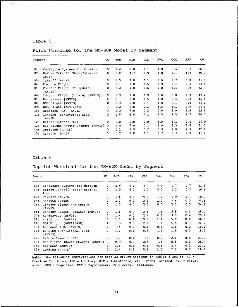
Table 5
Pilot Workload for the MH-60K Model by Segment
Segment OC AUD KIN VIS NVG COG PSY OW
01: Configure Systems for Mission 0 2.6 1.0 0.1 1.0 3.4 0.7 28.302: Before Takeoff (Base/Internal 0 1.2 4.7 0.9 1.8 3.1 1.9 40.2
Load)03: Takeoff [ANVIS] 0 1.5 7.0 0.1 2.0 2.7 3.0 46.504: Enroute Flight 0 i.1 1.0 0.5 0.9 3.1 0.3 23.505: Contour Flight (No Update) 0 1.3 7.0 0.5 0.8 3.4 2.9 45.7
[ANVIS]06: Contour Flight (Update) [ANVIS] 0 1.3 7.0 0.9 0.8 3.8 2.9 47.407: Rendezvous [ANVIS] 0 1.1 7.0 0.5 1.0 3.4 2.9 45.608: NOE Flight [ANVIS] 0 1.3 7.0 0.1 1.0 3.1 2.9 44.2
09: NOE Flight [ANVIS/ASE] 1 1.3 7.0 0.1 1.5 3.1 2.9 45.5
10: Approach (LZ) [ANVIS] 0 1.3 7.0 0.2 0.9 2.9 2.9 43.9
11: Landing (LZ/Internal Load) 0 1.0 6.6 0.1 2.5 2.5 2.7 44.1[ANVIS]
12: Before Takeoff (LZ) 0 1.8 1.0 0.0 1.0 3.1 0.4 24.9
13: NOE Flight (Route Change) [ANVIS] 0 0.8 7.0 0.1 1.0 2.5 2.8 41.5
14: Approach [ANVIS] 0 1.1 7.0 0.2 0.9 2.8 2.9 42.9
15: Landing [ANVIS] 0 1.2 6.8 0.1 2.7 2.7 2.8 46.2
Table 6
Copilot Workload for the MH-60K Model by Segment
Segment OC AUD KIN VIS NVG COG PSY al
01: Configure Systems for Mission 0 2.6 0.2 0.7 0.0 1.7 0.7 21.5
02: Before Takeoff (Base/Internal 0 1.3 0.1 1.2 0.2 1.3 0.7 18.6
Load)
03: Takeoff [ANVIS] 0 1.5 0.1 0.1 1.2 1.9 0.1 18.7
04: Enroute Flight 0 1.3 0.1 3.5 1.2 5.6 0.3 35.8
05: Contour Flight (No Update) 0 1.5 0.1 3.2 0.7 5.5 0.3 34.1[ANVIS]
06: Contour Flight (Update) [ANVIS] 0 1.5 0.1 2.5 1.5 5.5 0.3 35.007: Rendezvous [ANVIS] 0 1.4 0.1 2.4 0.2 3.3 0.4 25.8
08: NOE Flight [ANVIS] 0 1.3 0.1 3.3 1.2 5.9 0.2 36.009: NOE Flight [ANVIS/ASE] 1 1.3 0.1 2.0 1.8 5.5 0.7 34.710: Approach (LZ) (ANVIS] 0 1.4 0.1 0.1 0.9 1.9 0.2 18.1
11: Landing (LZ/Internal Load) 0 1.2 0.1 0.3 1.3 1.9 0.2 18.9[ANVIS]
12: Before Takeoff (LZ) 0 1.8 0.1 1.9 0.0 2.6 0.6 23.913: NOE Flight (Route Change) [ANVIS] 0 0.9 0.2 3.5 1.3 5.8 0.3 36.214: Approach [ANVIS] 0 1.5 0.1 0.9 0.6 2.4 0.3 21.115: Landing [ANVIS] 0 1.4 0.1 0.1 1.3 2.2 0.2 19.7
Note. The following abbreviations are used as column headings in Tables 5 and 6: OC =
Overload Condition, AUD = Auditory, KIN = Kinesthetic, VIS = Visual-unaided, NVG = Visual-
aided, COG = Cognitive, PSY = Psychomotor, OW = Overall Workload.
34
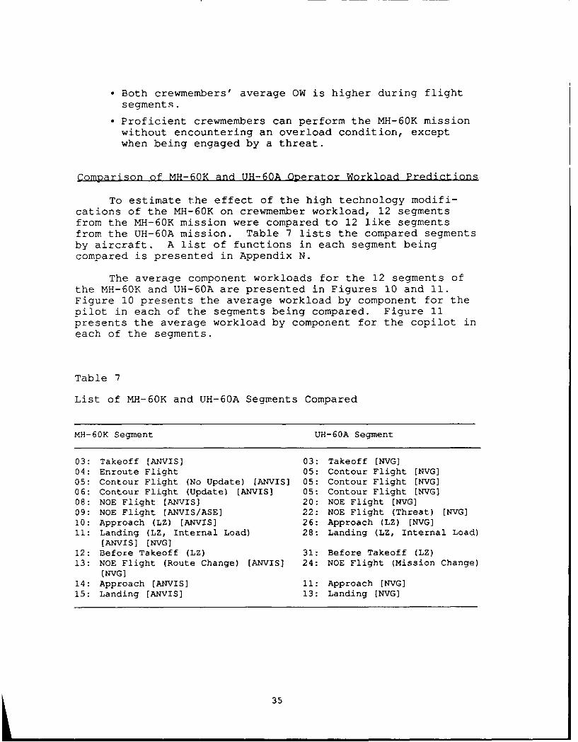
* Both crewmembers' average OW is higher during flightsegments.
" Proficient crewmembers can perform the MH-60K missionwithout encountering an overload condition, exceptwhen being engaged by a threat.
Comparison of MH-60K and UH-60A Operator Workload Predictions
To estimate the effect of the high technology modifi-cations of the MH-60K on crewmember workload, 12 segmentsfrom the MH-60K mission were compared to 12 like segmentsfrom the UH-60A mission. Table 7 lists the compared segmentsby aircraft. A list of functions in each segment beingcompared is presented in Appendix N.
The average component workloads for the 12 segments ofthe MH-60K and UH-60A are presented in Figures 10 and 11.Figure 10 presents the average workload by component for thepilot in each of the segments being compared. Figure 11presents the average workload by component for the copilot ineach of the segments.
Table 7
List of MH-60K and UH-60A Segments Compared
MH-60K Segment UH-60A Segment
03: Takeoff [ANVIS] 03: Takeoff [NVG]04: Enroute Flight 05: Contour Flight [NVG]
05: Contour Flight (No Update) [ANVIS] 05: Contour Flight [NVG]06: Contour Flight (Update) [ANVIS] 05: Contour Flight [NVG308: NOE Flight [ANVIS] 20: NOE Flight [NVG]09: NOE Flight [ANVIS/ASE] 22: NOE Flight (Threat) [NVG]10: Approach (LZ) [ANVIS] 26: Approach (LZ) [NVG]11: Landing (LZ, Internal Load) 28: Landing (LZ, Internal Load)
[ANVIS] (NVGj12: Before Takeoff (LZ) 31: Before Takeoff (LZ)
13: NOE Flight (Route Change) [ANVIS] 24: NOE Flight (Mission Change)[NVG]
14: Approach [ANVIS] 11: Approach [NVG]15: Landing [ANVIS] 13: Landing [NVG]
35

* UH-60A - PILOT* MH-60K - PILOT
8
28
04-
6-6

El UH-60A - COPILOTA MH-60K - COPILOT
6 -~J
2402-0
MH8KSemn
10 1 2 13 1 5 1
Fiue1.Cplts vrg opnn wrla ysget
CD 27

An analysis of the pilot workload by component graph(Fiqure 10) indicates little difference in the pilot audi-tory, visual-unaided, or cognitive predicted workload for thetwo aircraft. However, the kinesthetic, NVG, and psychomotorworkload differed in certain segments. For example, when allcontrols for the MH-60K are coupled during contour flight(Segment 04), the reduction in kinesthetic and psychomotorworkload is significant. The small increase in NVG workloadfor the MH-60K is a result of a requirement for the pilot tospend more time looking outside tLe aircraft.
The copilot workload by component graph (Figure 11)indicates there is no difference in the copilot auditory orkinesthetic predicted workload for the two aircraft. How-ever, eliminating the requirement in the MH-60K for thecopilot to handle maps, determine present position, andcalculate fuel requirements reduces the visual-unaided,cognitive, and psychomotor workload during contour and NOEflight (Segi ents 05, 06, 08, 09). This change also enablesthe copilot to spend r-ore time looking outside the aircraft,which produces the increase in NVG workload.
Predicted OW for the UH-60A and MH-60K is shown inFigure 12. The top figure compares the pilot's predicted OWfor the two aircraft. The bottom figure compares thecopilot's predicted OW for the two aircraft.
An examination of the pilot's predicted OW graph (Figure12) shows the effect of control coupling during contourflight (Segment 04) in the MH-60K. An examination of thecopilot's predicted OW graph (Figure 12) indicates a lower OWfor the MH-60K in nearly all segments. This finding reflectsthe copilot's reduced task requirements in the MH-60K, exceptfor the approach and landing segments (Segments 10, 11, 14,15).
38

i 00
-0'-- UH-60A - Pilot80 MH-60K - Pilot
0
"60._
O40CL
20
3 4 5 6 8 9 10 11 12 13 14 15
100
-- UH-60A - CopilotS80 MH-60K- Copilot
0
"60
S40
0-20
3 4 5 6 8 9 10 11 12 13 14 15Segment
Figure 12. Comparison of MH-60K and UH-60A predicted OW bysegment for the pilot (upper) and copilot (lower).
39

CONCLUSIONS
The workload prediction methodology developed by ARIARDAprovides a systematic means for estimating the workloadimpact of the advanced technology being proposed for newaircraft and the impact of modifications of existing air-craft. Under the conditions assumed during model development(e.g., proficient operators, optimal weather conditions)neither the UH-60A nor the MH-60K appears to place excessiveworkload demands on their operators. A comparison of theworkload for the pilot of the MH-60K and the UH-60A resultedin the following observations:
" In some segments, the MH-60K aircraft was found tohave higher NVG workload than the UH-60A. Theincrease in external visual attention may provide theMH-60K pilot with increased awareness of the statusand spatial location of the aircraft, of other airtraffic, and of threats to the aircraft.
" The MH 60K aircraft was found to have slightly lowervisual-unaided workload due to the reduction ofaircraft system monitoring which is automaticallyperformed by the integrated avionics subsystems.
" The MH-60K aircraft was found to have reducedkinesthetic and psychomotor workload when flightcontrols are coupled during Segment 04.
" The overall workload in the MH-60K was found to besimilar to the UH-60A in all segments except when thecontrols are coupled in the MH-60K.
A comparison of the copilot workload for the MH-60K andthe UH-60A resulted in the following observationsi
" The MH-60K aircraft was found to have reduced visual-unaided workload due to the reduced requirements formap interpretation because present position is alwaysreadily available on the MFD.
" The MH-60K aircraft was found to have higher NVGworkload than the UH-60A. The increase in externalvisual attention may provide the MH-60K copilot withincreased awareness of the status and spatial locationof the aircraft, of other air traffic, and of threatsto the aircraft.
41

• The MH-60K was found to have lower .ognitive workloadbecause functions such as fuel consumption, checkingsystem status, and determining present position areperformed continuously by the mission processor.
* The overall workload in the MH-60K was found to begenerally lower than the overall workload in UH-60A.
42

REFERENCES
Aldrich, T. B., Craddock, W., & McCracken, J. H. (1984). Acomputer analysis to predict crew workload during LHXscout-attack missions (Technical Report No. AS1479-054-84[B], Vols. I, II, III). Fort Rucker, AL: AnacapaSciences, Inc.
Bierbaum, C. R., Fulford, L. A., & Hamilton, D. B. (1989).Task analysis/workload (TAWL) user's guide (Report No.AS1690-323-89). Fort Rucker, AL: Anacapa Sciences,Inc.
Bierbaum, C. R., Szabo, S. M., & Aldrich, T. B. (1989). Taskanalysis of the UH-60 mission and decision rules fordeveloping a UH-60 workload prediction model. Volume I:Summary report (Research Product 89-08). Alexandria,VA: U.S. Army Research Institute for the Behavioral andSocial Sciences. (AD A210 763)
Iavecchia, H. P., Linton, P. M., Bittner, A. C., Jr., &Byers, J. C. (1989). Operator workload in the UH-60ABlack Hawk: Crew results vs. TAWL model predictions.In Proceedings of the Human Factors Society. 33rd AnnualMeeting. Santa Monica, CA: Human Factors Society.
McCracken, J. H., & Aldrich, T. B. (1984). Analyses ofselected LHX mission functions: Implications foroperator workload and system automation goals (TechnicalNote AS1479-024-84[B]). Fort Rucker, AL: AnacapaSciences, Inc.
Szabo, S. M., & Bierbaum, C. R. (1986). A comprehensive taskanalysis of the AH-64 mission with workload estimatesand preliminary decision rules for developing an AH-64workload prediction model (Technical Report No. AS1678-204-86[B], Vols. I, II, III, and IV). Fort Rucker, AL:Anacapa Sciences, Inc.
Wickens, C. D. (1984). Engineering psychology and humanperformance. Columbus, OH: Merrill.
43