Embed Size (px)
Citation preview

MODEL MP FREIGHT DOOR CONTROL Installation and Adjustment
Courion 3044 Lambdin Avenue Saint Louis, MO 63115
(800) 533-5760
THE INFORMATION CONTAINED IN THIS DOCUMENT SET IS THE EXCLUSIVE PROPERTY OF COURION,
COMPREHENSIVE MANUFACTURING SERVICES, L.L.C. ANY REPRODUCTION OR DISSEMINATION OF THE CONTENTS,
DESIGNS OR IDEAS CONTAINED HEREWITH IS HEREBY FORBIDDEN.

COURION MODEL MP/MPG2 CONTROL WIRING AND ADJUSTMENTS
INTRODUCTION
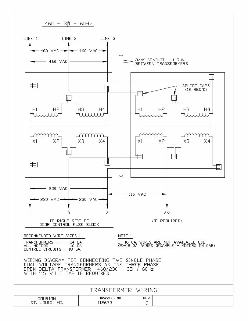
CONTROL WIRING AND ADJUSTMENTS All functions of the Courion freight door control have been tested to insure proper operation. Most control malfunctions result from hoistway wiring errors or loose connections. When wiring the hoistway and car using pre-numbered wire bundles, keep a detailed cross reference list with the control designations to facilitate future maintenance. Hardware to mount the control enclosures to the machine room wall is included as Hardware Kit #120. One kit is required for each enclosure. If transformers are required, hardware to mount the transformers is included as Hardware Kit #125. One kit is required to mount each pair of transformers. Wire the hoistway and car according the Courion control schematic drawing and the related hoistway connection diagram. On Courion electrical drawings, field wiring is shown dashed and all switches are shown with the power off, the car gate and hoistway door closed and locked, and the car stopped between floors. IMPORTANT! When the power supply exceeds 260 VAC, step down transformers are supplied by Courion. These transformers should be mounted near the door control enclosure. Two single phase transformers are wired in a polyphase bank to provide three phase voltage transformation. Drawing 112673 illustrates typical transformer wiring. DO NOT USE ANY OTHER CONFIGURATION WHEN WIRING THE POLYPHASE TRANSFORMER BANK. When wiring the "Q" interlocks, refer to the diagram on the inside of the interlock cover as an aid in identification of interlock, zone and door closed contacts. When wiring the “PA” interlocks, refer to the terminal cross reference on the Hoistway connection diagram. Be sure to properly locate type “PAE” interlocks only at floors with emergency unlocking devices. After wiring the “PA” interlocks, check adjustment of the roller lever as indicated on Drawing PO-70-3A. When converting from an earlier Courion Freight Door Control (Model D, Model E), please refer to the following section on Freight Door Control Replacement.


COURION MODEL MP/MPG2 CONTROL WIRING AND ADJUSTMENTS
FREIGHT DOOR CONTROL REPLACEMENT IMPORTANT! Be sure to review all attached information before attempting field retrofit of the
new Model MP Door Control. While the modifications required are not normally difficult, proper planning will save hours of field time and reduce lift down time.
GENERAL The Model MP Door Control differs from previous Courion door controls in a number of significant ways. The principal difference affecting field retrofit of the control is the separation of motor power distribution and control logic. In most existing controls, the door logic operates at the motor voltage - nominally 230VAC. The Model MP Door Control operates control logic at 115VAC (nominal), separate from the 230VAC motor power distribution legs. In addition, all (3) legs of each motor circuit (door, car gate and retiring cam) are switched - there is no "common" wire between these motors. You must completely separate the door control logic from the motor power distribution circuitry, and provide separate motor feeds for the door motors, gate motor(s) and retiring cam(s). Depending on the wiring practice and number of spares provided, separation of the motor power distribution and control logic circuits is not a difficult task. With the new door control, we supply a new hoistway wiring diagram if there are changes required to the hoistway wiring. In addition, we supply a copy of the original hoistway wiring diagram (when available) for reference. Your goal is to convert the existing field wiring shown on the original hoistway wiring diagram to the configuration shown on the new hoistway wiring diagram. A little study of these diagrams will reveal the most efficient way to separate the existing wiring. When converting from any Courion door control except the Model E Door Control, wiring of the car gate reversing edge micro-switch must be changed from a normally open contact to a normally closed contact (the microswitch circuit breaks when the reversing edge is activated).

COURION MODEL MP/MPG2 CONTROL WIRING AND ADJUSTMENTS
MODEL E TO MODEL MP CONVERSION When converting from a Model E Door Control to a Model MP Door Control, no changes in hoistway wiring are required. The Model MP Door Control does not have the following terminals:
DCB, DCT, DLB, DLT, G1, G2 These junction terminals were provided as a convenience in terminating hoistway wires destined for the elevator control and have no connection to the Door Control itself. If there are wires joined together at these terminals, splice together the wires originally connected to each terminal – there is no need to connect these wires to the Model MP Door Control. For example, if there are two wires in the DCB terminal, remove these two wires from the terminal, use a wire cap to join the wires together and label the wire group with the original terminal designation. Repeat for each terminal with more than one wire connection. If you find a single wire inserted into a terminal, remove the wire from the terminal, label the wire with the original terminal designation, and cap the wire to prevent a short against the enclosure. Some Model E Door Controls use relays and field connection terminals exterior to the main logic board. These are usually located on a DIN rail near the top of the back panel. No external relays are necessary for the Model MP Door Control. Use the following chart to determine the proper location for connection of these wires to the Model MP control:
Model E Control Terminal Connects to Model MP Terminal 8B 8B (located near contactors at the
bottom of the control 21A 21 22FS 22
Please call Courion Engineering at 800-533-5760 if you have any questions with this material.

COURION MODEL MP/MPG2 CONTROL WIRING AND ADJUSTMENTS
ADJUSTMENT
RETIRING CAM ADJUSTMENT There are two styles of retiring cam power units. The units are most easily identified by the presence or absence of an air check on the power unit.
• AIR CHECK
The retiring cam is adjusted with the air check located on the retiring cam power unit, and resistor R3 located at the top of the door control panel. To adjust the retiring cam unit, first make sure the chain from the power unit to the top of the cam is not slack. The arms on the cam should be horizontal. Manually pick and drop the cam, adjusting the air check until the drop is smooth. At the control, pick the cam under power, and adjust the resistor on the control board until the cam picks smoothly. As the resistance is increased, the power developed by the motor decreases.
• NO AIR CHECK
The retiring cam is adjusted with V-Belt tension on the retiring cam power unit, and resistor R3 located at the top of the door control panel. To adjust the retiring cam unit, first make sure the chain from the power unit to the top of the cam is not slack. The arms on the cam should be horizontal. Manually pick and drop the cam, adjusting tension of the v-belt between the motor and the cam pulley until the drop is smooth. The tension is increased by moving the motor mount away from center. At the control, pick the cam under power, and adjust the resistor on the control board until the cam picks smoothly. As the resistance is increased, the power developed by the motor decreases.
DOOR ADJUSTMENTS There are two types of door limit switches. The QLS limit switch contains both the DOOR OPEN and DOOR CLOSE contacts in a single switch, located just under the DOOR OPERATOR on the interlock side. The type L limit switch is a single contact switch used in pairs. One type L limit switch is mounted above the interlock for use as a DOOR CLOSED contact, while the other type L limit switch is mounted below the interlock for use as a DOOR OPEN contact.

COURION MODEL MP/MPG2 CONTROL WIRING AND ADJUSTMENTS
• TYPE QLS DOOR LIMIT SWITCH (SINGLE)
The door open and door close limit switches are located in a single QLS limit switch mounted just under the door motor/operator on the interlock side. The door open and door close limit switches must be set before adjusting the control resistors. The QLS limit switch is actuated by OPEN and CLOSE cams attached to the bottom and top of the upper door panel. The positioning of these cams determines where the braking cycle begins. If the door slams without hesitating, move the appropriate cam towards the center of the opening. If the door hesitates or stops more than two inches from the end of travel, move the appropriate cam away from the center of the opening.
• TYPE L DOOR LIMIT SWITCH (PAIRED)
The door open limit switch is located beneath the interlock, near the entrance sill. The door close limit switch is located above the interlock, near the entrance head. Both switches are individually piped using a flexible conduit. Adjustment is made by changing the mounting location of the switch in the pre-punched series of mounting holes. The door open and door close limit switch positions must be set before adjusting the control resistors. The type “L” limit switches are actuated by the lock bar attached to the lower door arm on the interlock side. Positioning of the type “L” limit switches determines where the braking cycle begins. If the door slams without hesitating, move the appropriate switch towards the center of the opening. If the door hesitates or stops more than two inches from the end of travel, move the appropriate switch away from the center of the opening.
CAR GATE ADJUSTMENTS
The car gate open and close limit switches are located in a single switch. This switch may be either a rotary (traveling nut) design, or a geared (circular cam) design. The rotary limit switch is set by moving the location of the internal brass adjusting nuts along the shaft. The geared limit switch is set by moving the location of two plastic cams mounted to a gear. The car gate drive belt tension must be properly set before attempting adjustment of the rotary limit switch under power. Adjust the cams/traveling nuts to obtain braking no more than two inches from fully open and no more than two inches from fully closed.


COURION MODEL MP/MPG2 CONTROL WIRING AND ADJUSTMENTS
CONTROL ADJUSTMENTS The Model MP control has several adjustment settings. These settings should only be changed AFTER completion of all limit switch adjustments detailed in previous sections. All adjustments to the Model MP control are accessed through the display and keypad on the microprocessor panel. The menu tree is diagrammed below.
NOTE:
Pressing RUN/PGM at any
time will return the control
to the RUN mode
NOTE:
Pressing ESC at any time
will revert to the previous
menu.
SEE INPUT MONITOR
SECTION
SEE TIMER
ADJUSTMENT SECTION
SEE TIMER
ADJUSTMENT SECTION
SEE TIMER
ADJUSTMENT SECTION
SEE TIMER
ADJUSTMENT SECTION
SEE TIMER
ADJUSTMENT SECTION
SEE TIMER
ADJUSTMENT SECTION
CONTINUED ON NEXT
PAGE

COURION MODEL MP/MPG2 CONTROL WIRING AND ADJUSTMENTS

COURION MODEL MP/MPG2 CONTROL WIRING AND ADJUSTMENTS
INPUT MONITOR The Model MP Door Control Input Monitor displays the current status of each monitored input to the control. The following chart describes the normal status and function of each monitored input. After entering Input Monitor mode, use the UP and DOWN arrow keys on the keypad to scroll through the monitored inputs. Press the ESC button to exit the Input Monitor, or the RUN/PGM button to exit the Input Monitor and return to the RUN condition. Normal status of the inputs is given with the hoistway doors and car gates fully closed and the car parked at a floor with the retiring cam dropped. DISPLAY & NORMAL STATUS FUNCTION IN2(RESET) = OFF Motor Protection Timer Reset
This optional input is used to allow an external signal to reset the motor protection timer following a fault. The motor protection logic turns off the control outputs if the hoistway door or car gate cannot complete an open or close cycle within the time period specified by the MOTOR PROT TMR control parameter. The reset input is high only when an external reset signal is present. A normal reset signal is three seconds in duration. A continuous input indicates a fault in the external reset circuitry – either from a stuck external pushbutton (if present) or from the lift control (if so designed).
IN3(FEO2)=OFF Emergency Firefighters Operation Phase II This input signals the Model MP door control to operate the hoistway doors and car gates in accordance with the rules of Emergency Firefighters Operation Phase II. This input should only be ON when the lift is operating in Emergency Firefighters Operation Phase II mode.
IN4(DOL)=ON Hoistway Door Open Limit This input is ON unless any hoistway door is positioned past the open slow down limit switch.

COURION MODEL MP/MPG2 CONTROL WIRING AND ADJUSTMENTS
DISPLAY & NORMAL STATUS FUNCTION IN5(DCL)=OFF Hoistway Door Closed Limit
This input is ON unless all hoistway doors are positioned past the close slow down limit switch.
IN6(GOL)=ON Car Gate Open Limit This input is ON unless any car gate is positioned past the open slow down limit switch.
IN7(GCL)=OFF Car Gate Close Limit This input is ON unless all car gates are positioned past the close slow down limit switch.
IN8(RE)=ON Car Gate Reversing Edge This input is ON unless the car gate reversing edge is actuated or unless the car gate light curtain is actuated during the close cycle. If this input is OFF, the close cycle will not initiate and any open cycle initiated from the fully closed position will result in the hoistway door and car gate opening fully, followed by a motor protection timer trip. Check the car gate reversing edge switch for proper operation and the car gate reversing edge circuit wiring for breaks.
IN9(SS)=OFF Automatic Stay Set Switch The automatic stay set switch is optional. If no automatic stay switches are present, this input will always be OFF (no field wire or jumper attached to terminal 9). The switch is supplied on all Class C freight elevators with a capacity of 10,000 pounds or greater and all Class B garage elevators. The switches are located one per floor and are wired in series. Normal status of this input when automatic stays set switches are present is ON. Any door within ¾” of fully open will open the automatic stay set switch and change the input state to OFF.

COURION MODEL MP/MPG2 CONTROL WIRING AND ADJUSTMENTS
DISPLAY & NORMAL STATUS FUNCTION IN11(CAM)=OFF Retiring Cam
This input is ON only when the cam is to retire.
IN15(SC)=ON Safety Circuit This input is ON when all of the following conditions are TRUE:
� All safety access device switches are closed (emergency unlocking devices, if present, are all closed and locked).
� The cam is dropped on an interlock, and the control zone contact (located in the interlock) is made.
� The car DOOR STOP button is not actuated. � The car is not on INSPECTION operation.
This input must be ON for door/gate operation.
IN18(AO)=OFF Automatic Open This input is ON only when the lift control commands the door control to open the doors following arrival at a landing. The input is momentary, and should be released after the open cycle has been established.
IN21(OPEN)=OFF Open Button This input is ON only when either the car DOOR OPEN button or hall station DOOR OPEN button is actuated.
IN22A(CC)=OFF Car Close Button This input is ON only when the car DOOR CLOSE button is actuated. This input will establish either a constant pressure close cycle or a momentary pressure close cycle dependant on the setting of the MPPB ENABLE control parameter. If MPPB ENABLE is set to ON, the closing cycle will be momentary pressure, initiated WITHOUT delay.

COURION MODEL MP/MPG2 CONTROL WIRING AND ADJUSTMENTS
DISPLAY & NORMAL STATUS FUNCTION IN22B(HC)=OFF Hall Close Button
This input is ON only when the hall DOOR CLOSE button is actuated. This input will establish either a constant pressure close cycle or a momentary pressure close cycle dependant on the setting of the MPPB ENABLE control parameter. If MPPB ENABLE is set to ON, the closing cycle will be momentary pressure, with a pre-close warning. The duration of the pre-close warning is set with the WARNING BELL TMR control parameter.
IN23(FEO2H)=ON Firefighters Emergency Operation Phase II Hold This input is ON unless the in car Firefighters Emergency Operation Phase II key switch is in the HOLD position. When this input is OFF, door/gate closing is inhibited. If the lift does not have Fire Service, a jumper must be supplied between terminals 22 and 23 to set the status of this input to ON.
IN25(FEO1)=OFF Firefighters Emergency Operation Phase I Recall Close This input is used to establish a remote close of open doors and gates during Firefighters Emergency Operation Phase I Recall operation. This circuit is functional only if the MPPB ENABLE control parameter is set ON.
IN25(FEO1)=OFF Firefighters Emergency Operation Phase I Recall Close This input is used to establish a remote close of open doors and gates during Firefighters Emergency Operation Phase I Recall operation. This circuit is functional only if the MPPB ENABLE control parameter is set ON.

COURION MODEL MP/MPG2 CONTROL WIRING AND ADJUSTMENTS
DISPLAY & NORMAL STATUS FUNCTION IN27(TCKO)=OFF Timed Close Cut Out
This input is high only if timed close operation of the hoistway doors and car gates is enabled. If timed close is enabled through this input, the period before a door close cycle is initiated following the open cycle is set with the TIMED CLOSE control parameter. Timed Close is normally used only with momentary pressure push button operation (control parameter MPPB ENABLE set ON). This input must be OFF when the lift is operating in Firefighters Emergency Operation.
IN30(RG)=OFF Rear Car Gate Selector On lifts with staggered entrances (two car gates but no walk through landings), this input is ON to select REAR car gate operation. This selection is made through a zone contact in the REAR entrance interlocks. When this input is OFF, the Front car gate is selected.

COURION MODEL MP/MPG2 CONTROL WIRING AND ADJUSTMENTS
TIMER ADJUSTMENT
DISPLAY FUNCTION MIN MAX DEFAULT MOTOR PROT TMR Motor Protection 30s 60s 60s WARNING BELL TMR Warning Bell Duration 5s 15s 5s TIMED CLOSE Timed Close Period 1.0m 100m 1.0m DOOR BRAKE TIME Door Braking Duration 1.0s 3.0s 1.0s GATE BRAKE TIME Gate Braking Duration 1.0s 3.0s 1.0s FINAL O/C TIME Final Open/Close Duration 1.5s 3.5s 1.5s
MOTOR PROT TMR (Motor Protection)
The motor protection timer setting determines how long the OPEN or CLOSE cycle may be energized before the control will drop power to protect the motors. If the motor protection timer is tripped, the display will read MPT TRIP. The control must be reset to restore power operation of the hoistway doors and car gate. The control may be reset by either of the following methods:
• An external dry contact may be momentarily closed between terminals 1 and 2.
• Power to the door control may be cycled.
WARNING BELL TMR (Warning Bell Duration) The warning bell timer setting determines how long the warning bell will sound prior to CLOSE operation when closing with momentary pressure push button operation (control parameter MPPB ENABLE set ON).
TIMED CLOSE (Timed Close Period) The timed close setting determines how long a door will stand open before a CLOSE cycle is automatically established when timed close is active. IMPORTANT! Timed Close must always be disabled during Emergency Firefighters Service Operation. Timed Close requires an audible warning device present on the car.

COURION MODEL MP/MPG2 CONTROL WIRING AND ADJUSTMENTS
DOOR BRAKE TIME (Door Braking Duration)
The door brake time setting establishes how long the control will apply direct current braking to the door motor at the end of each OPEN or CLOSE cycle. Increasing this setting from the default is rarely necessary and should be done only after assuring all mechanical settings are proper.
GATE BRAKE TIME (Gate Braking Duration) The gate brake time setting establishes how long the control will apply direct current braking to the gate motor at the end of each OPEN or CLOSE cycle. Increasing this setting from the default is rarely necessary and should be done only after assuring all limit switch settings are proper and the linkage from the motor to the car gate operator is sound.
FINAL O/C TIME (Final Open/Close Duration) Following braking, the control will re-apply A.C. power to the motors to complete the final 1 to 2 inches of travel. The final open/close time setting determines how long this power will be applied to the motors after both the hoistway door and car gate have completed their respective braking cycle. It is rarely necessary to increase this setting from the default and should be done only after assuring other adjustments have been completed and the door and car gate are braking to a stop no more than 2 inches from end of travel in each direction.
MPPB ENABLE MODE ADJUSTMENT
The Model MP control may be operated in either constant pressure push button close operation (default) or momentary pressure push button close operation. Selection of operational mode is done at the MPPB ENABLE menu as shown above.

COURION MODEL MP/MPG2 CONTROL WIRING AND ADJUSTMENTS
When MPPB ENABLE is set to ON, the following applies:
• An audible warning device must be installed on the car top. The Model MP control provides a 115VAC output between terminals 29 (line) and 35 (neutral) for driving either a low current signaling device or a pilot relay for use with high current signaling devices.
• Firefighters Emergency Operation Phase 1 Recall requires remote close of open doors. This signal must be available from the lift control.
SPEED ADJUSTMENT
This section is more appropriately labeled torque adjustment. The four “speed” adjustment settings control the amount of torque the motor can generate following the braking period. Adjustment of these settings should be made ONLY after all limit switch settings have been completed. The length of the bar graph is proportional to the torque available at the motor – the longer the bar, the more torque the motor can produce. For each mode (door open, door close, gate open and gate close), reduce the motor torque until the final 1 or 2 inches of travel is adequately softened.

MODEL MP CONTROL MESSAGES
The Model MP Control displays informational and error messages on a two line LED
display located on the main microprocessor board. The following table summarizes the
messages:
DISPLAY SYMPTOM REQUIRED ACTION
SELF TEST
FAILED
WATCHDOG
Power On self test failure – watchdog
timer Replace Microprocessor Board
SELF TEST
FAILED
EEPROM
Power On self test failure – EEPROM
failure Replace Microprocessor Board
SELF TEST
FAILED
ROM CKSUM
Power On self test failure – Program
memory checksum not valid Replace Microprocessor Board
BAD EEPROM
PROG MODE
ONLY
EEprom is working, but default values do
not match Microprocessor Board
Enter and Exit the Program Mode to
re-initialize the EEPROM. This
most often happens after a chip
replacement.
COURION
DOOR MOTOR
TRIP
Door Motor current has exceeded 10A
RMS.
Check door motors and wiring to the
door motors.
COURION
GATE MOTOR
TRIP
Gate Motor current has exceeded 10A
RMS.
Check gate motor(s) and wiring to
the gate motors.
COURION
DOOR MIT TRIP
Door Motors have exceeded their duty
cycle.
Perform a control reset by cycling
the power. Determine why door
operation exceeded the duty cycle of
the motor.
COURION
GATE F MIT
TRIP
Front gate motor(s) design duty cycle
exceeded.
Perform a control reset by cycling
the power. Determine why front
gate operation exceeded the duty
cycle of the motor.
COURION
GATE R MIT
TRIP
Rear gate motor(s) design duty cycle
exceeded.
Perform a control reset by cycling
the power. Determine why rear gate
operation exceeded the duty cycle of
the motor.
COURION
MPT TRIP
The door/gate operation exceeded the
Motor Protection Time setting (30
seconds minimum)
Perform a control reset by cycling
the power or momentarily jumping
terminal 1 to 2. Determine why the
open or close cycle could not be
completed in the set time period.

RE TRIPPED The car gate reversing edge is actuated.
If the display is persistent,
determine why the car gate
reversing edge circuit between
terminals 1 and 8 is not complete.
This circuit is normally made and
breaks when the car gate reversing
edge is actuated or when the cable to
the reversing edge is broken.
FSII HOLD ON Fire Service Phase II “Hold” is active.
The Phase 2 Hold circuit between
terminals 22 and 23 is open,
indicating the control is on Fire
Service Phase 2 Hold operation.
The doors will not close under
power until the circuit is closed.
COURION
RETIRING CAM
CMD
The control is executing a command to
retire the cam (requires an input from the
lift control and doors in the fully closed
position)
Informational. No action required.
COURION
DOOR/GATE
HOLD
The control is receiving an input to open
or close, but the door and car gate are
already fully open or closed.
Informational. No action required.
COURION
DOOR OPENING
The control is opening the hoistway
doors. Informational. No action required.
COURION
DOOR/GATE
OPEN
The control is opening both the hoistway
doors and the car gate. Informational. No action required.
COURION
GATE OPENING The control is opening the car gate. Informational. No action required.
COURION
DOOR CLOSING The control is closing the hoistway doors. Informational. No action required.
COURION
DOOR/GATE
CLOSE
The control is closing both the hoistway
doors and the car gate. Informational. No action required.
COURION
GATE CLOSING The control is closing the car gate. Informational. No action required.
COURION
CLOSE
WARNING
The control is issuing a close warning in
preparation for automatically closing the
doors. The will sound the warning bell
(low current, 115VAC) attached between
terminals 29 and 35.
Informational. No action required.
COURION
WAITING FOR
CALL
The control is operational, but idle. Informational. No action required.

MODEL MP CONTROL CONTACTOR FUNCTION
The Model MP Control contactors are located near the bottom of the control panel
mounted to a horizontal DIN rail. Routinely check to be sure the contactors are not
pressed too tightly together along this rail. A piece of paper should slip easily between
each contactor or contactor and mechanical interlock. The following table summarizes
the function of each contactor:
CONTACTOR FUNCTION
O (OPEN) Connects the power in phasing for door and car gate opening.
C (CLOSE) Connects the power in phasing for door and car gate closing.
DP (DOOR
POTENTIAL) Connects the phased power to the door motors for normal operation.
DB (DOOR
BRAKING) Connects rectified (D.C.) power to the door motors for braking.
GP (GATE
POTENTIAL) Connects phased power to the gate motor(s) for normal operation.
GB (GATE
BRAKING) Connect rectified (D.C.) power to the gate motor(s) for braking.
RC (RETIRING
CAM) Connect power to the retiring cam motor (retire cam).
S (SELECTOR) Selects “rear” gate operation – on Model MPG2 controls only.
Courion Freight Door Control - Model “MP”Inter-Control Interface Circuit Descriptions
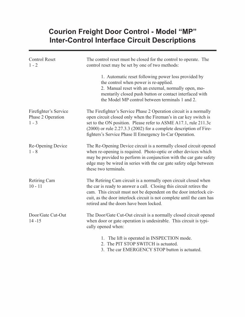
Control Reset1 - 2
Firefighter’s ServicePhase 2 Operation1 - 3
Re-Opening Device1 - 8
Retiring Cam10 - 11
Door/Gate Cut-Out14 -15
The control reset must be closed for the control to operate. The control reset may be set by one of two methods:
1. Automatic reset following power loss provided by the control when power is re-applied.2. Manual reset with an external, normally open, mo-mentarily closed push button or contact interfaced with the Model MP control between terminals 1 and 2.
The Firefighter’s Service Phase 2 Operation circuit is a normally open circuit closed only when the Fireman’s in car key switch is set to the ON position. Please refer to ASME A17.1, rule 211.3c (2000) or rule 2.27.3.3 (2002) for a complete description of Fire-fighters’s Service Phase II Emergency In-Car Operation.
The Re-Opening Device circuit is a normally closed circuit opened when re-opening is required. Photo-optic or other devices which may be provided to perform in conjunction with the car gate safety edge may be wired in series with the car gate safety edge between these two terminals.
The Retiring Cam circuit is a normally open circuit closed when the car is ready to answer a call. Closing this circuit retires the cam. This circuit must not be dependent on the door interlock cir-cuit, as the door interlock circuit is not complete until the cam has retired and the doors have been locked.
The Door/Gate Cut-Out circuit is a normally closed circuit opened when door or gate operation is undesirable. This circuit is typi-cally opened when:
1. The lift is operated in INSPECTION mode.2. The PIT STOP SWITCH is actuated.3. The car EMERGENCY STOP button is actuated.

Courion Freight Door Control - Model “MP”Inter-Control Interface Circuit Descriptions
Automatic Opening17 - 18
Hall Station Cut-Out19 - 20
Firefi ghter’s ServicePhase 2 Hold Operation22 - 23
Firefi ghter’s ServicePhase 1 EmergencyRecall Operation24 - 25
Automatic Timed CloseCut-Out26 - 27
The Automatic Opening circuit is a normally open circuit mo-mentarily closed to initiate door and gate opening after the car has leveled. This circuit should be open when the doors have fully opened. This circuit should momentarily re-close in response to a car registered at a fl oor where the car is already present.
The Hall Station Cut-Out is a normally closed circuit opened to disable corridor door OPEN and CLOSE buttons. This circuit must be opened on Firefi ghter’s Service Phase 2 operation except during transition from Phase 2 to Phase 1 operation. This circuit may be opened during ATTENDANT operation.
The Firefi ghter’s Service Phase 2 Hold circuit is a normally closed circuit opened when the Fireman’s in car key switch is set to the HOLD position.
During Firefi ghter’s Service Phase 2 Hold operation, if the Phase 2 switch is placed in the OFF position, the car is not at the designat-ed level and Phase 1 operation is not in effect, the Phase 2 HOLD circuit should be opened to disable the CLOSE buttons and allow the door to open.
For controls set up for Momentary Close Operation only, the normally open Phase 1 Emergency Recall circuit may be closed to initiate remote closing. This circuit must be opened when the car has arrived at the designated level. This circuit is disabled when the Fireman’s in car key switch is set to the ON position.
For controls set up for Automatic Timed Close only, the Automat-ic Timed Close Cut-Out circuit is a normally closed circuit opened to prevent automatic timed closing of the freight elevator doors. This circuit must be opened when the car has arrived at the desig-nated level during Firefi ghter’s Service Phase 1 Recall Operation. This circuit is disabled when the Fireman’s in car key switch is set to the ON position.
This circuit may also be opened during ATTENDANT operation of the lift to prevent automatic timed closing of the freight doors.

Courion Freight Door Control - Model “MP”Inter-Control Interface Circuit Descriptions
Auxiliary Door ClosedCircuit40 - 41
Door Not Closed Circuits42 - 43
42 - 44
Door Not Open Circuits45 - 46
45 - 47
Firefi ghter’s ServicePhase 2 to Phase 1Transition
• Re-Activate Hall Stations 19 - 20
• Re-Activate Phase 2 or HOLD 22 - 23
The Auxiliary Door Closed circuit will close following the door close operation. This circuit is used to signal the elevator control to retire the cam in response to a call.
The Door Not Closed circuit between terminals 42 and 43 is open when the doors are not closed. This circuit may be used to cancel the Automatic Opening signal (17 - 18) if the elevator control does not independently provide this function.
The Door Not Closed circuit between terminals 42 and 44 is closed when the doors are not closed. This circuit may be used to sound a door open bell in response to a call.
The Door Not Open circuit between terminals 45 and 46 is open when the doors are not open. This circuit may be used to signal the elevator control to activate Firefi ghter’s Service Phase 2 Hold Operation when required.
The Door Not Open circuit between terminals 45 and 47 is closed when the doors are not open.
During the Transition from Firefi ghter’s Service Phase 2 Opera-tion to Phase 1 Operation (and while the lift is not at the designated landing and the landing doors are not closed), the following special interconnections apply:
The Hall Station Door Open and Door Close buttons should be activated by re-closing the Hall Station Cut-Out cicuit during the transition period. This circuit must be re-opened when either Phase 1 Operation is resumed or Phase 2 Operation is re-activated.
If the Firefi ghter’s in car key switch is turned from OFF to either HOLD or ON during the transition from Phase 2 to Phase 1 Op-eration while the doors are closing, the losing cycle must be inter-rupted and the door and gate re-opened. The re-open sequence is accomplished by opening the normally closed HOLD circuit between terminals 22 and 23 to break the close cycle and establish the re-open cycle. The normally closed HOLD circuit may be re-established when the door and gate have fully opened.

Courion Freight Door Control - Model “MP”Inter-Control Interface Circuit Descriptions
• Re-Activate Phase 2 or Hold (continued)
Door Interlock CircuitDLB - DLT
Door Closed CircuitDCB - DCT
Car Gate Closed CircuitG1 - G2
The Firefighter’s Service Phase 2 Operation circuit (1 - 3) should remain closed until Phase 1 Operation is resumed following the transition period.
NOTE!Instructions on the use of the Courion Model MP door control circuits to control door operation during Firefighter’s Emergency Operation and various transitions are not intended to be inclusive. Please refer to ASME A17.1 Rule 211.3 (2000) or Rule 2.27.3 (2002) for a complete description of the performance requirements.
The Door Interlock circuit is closed only when all doors in the hoistway are in the closed and locked position. Individual inter-lock contacts must be monitored for use with hoistway access key switches when required. This circuit is shown on the hoistway connection wiring diagrams and pull sheets supplied by Courion, but does not interface with the Courion Model MP door control. This circuit is intended for use with the lift control.
The Door Closed circuit is closed when all the doors in the hoist-way are closed. The Door Closed Circuit is shown on the hoist-way wiring diagrams and pull sheets supplied by Courion, but does not interface with the Courion Model MP door control. This circuit is intended for use with the lift control. This circuit may be used with the Auxiliary Door Closed circuit (40 - 41) to determine when the doors are closed and at rest.
The Car Gate Closed circuit is closed only when the car gate is in the closed position. The Car Gate Closed circuit is shown on the hoistway wiring diagrams and pull sheets supplied by Courion, but does not interface with the Courion Model MP door control. This circuit is intended for use with the lift control.
Please note - The Door Interlock Circuit, Door Closed Circuit and Car Gate Closed Circuit are not interfaced with circuitry in the Model MP Door Control and are wired directly to the lift control.


MODEL MP FREIGHT DOOR CONTROL Schematic Diagram
Courion 3044 Lambdin Avenue Saint Louis, MO 63115
(800) 533-5760
THE INFORMATION CONTAINED IN THIS DOCUMENT SET IS THE EXCLUSIVE PROPERTY OF COURION,
COMPREHENSIVE MANUFACTURING SERVICES, l.l.C. ANY REPRODUCTION OR DISSEMINATION OF THE CONTENTS,
DESIGNS OR IDEAS CONTAINED HEREWITH IS HEREBY FORBIDDEN.

F1FRN 6.25
F2FRN 6.25
F3FRN 6.25
230 VAC 3-PHASEPOWER SUPPLYCONNECTION TO
1 – 3 - 5
12
34
56
FUSE BLOCK
P1
P2
P3
60
PWR-H1ON POWER CONTROL BOARD
AC
35
GNDCPU-H1
1A
CPU-H10
67
66
1
2
CPU-H12
F5-16 TRANSFORMER120/12
X1 X2
H1H2
T150 TRANSFORMER240/120
230VAC POWER FOR
MOTORS
120 VAC POWER FOR
INPUT/OUTPUT
12VAC x2 FOR CPU
MICROPROCESSOR BOARD
H
G
F
E
D
C
B
A
8 7 6 5 4 3 2 1
H
G
F
E
D
C
B
A
8 7 6 5 4 3 2 1
58
61
59
62
Revision 0Model MP Control Sheet 1 of 4
1

PWR-H4-1P3 O
C
RC
63
28
5 6
5 6
5 6
DP
GP
PWR-H4-2P2 O
C
RC
64
27
3 4
3 4
3 4
37
PWR-H4-3P1 O
C
RC
65
26
1 2
1 2
1 2
DP
GP
31
36
PWR-H4-4O4
5 6
5 6
1 2
1 2
PWR-H4-5O6
34
PWR-H3-10DM3
52
PWR-H4-8DB5 DB
5 640
PWR-H3-1RC3
47
PWR-H3-2RC2
46
29
30PWR-H3-12
DM1
48
PWR-H3-9GMF1
53
250 OHM 100W44
PWR-H3-3RC1
45
PWR-H4-6DP3
PWR-H4-7DB3
PWR-H4-9GP3
PWR-H4-10GB3
DP
DB
3 4
3 4
38
39
PWR-H3-11DM2
50
49
GP
GB
3 4
3 4
PWR-H3-8GMF2
55
54
41
42
51
PWR-H3-7GMF3
57
PWR-H4-11GB5 GB
5 643 56
25
23
24
3532
33 H
G
F
E
D
C
B
A
8 7 6 5 4 3 2 1
H
G
F
E
D
C
B
A
8 7 6 5 4 3 2 1
Revision 0Model MP Control Sheet 2 of 4
NOTE: For Model MPG2 Controls (with Gate Selector (GS) Contactor) – See Sheet 3

PWR-H4-1P3 O
C
RC
63
28
5 6
5 6
5 6
DP
GP
PWR-H4-2P2 O
C
RC
64
27
3 4
3 4
3 4
37
PWR-H4-3P1 O
C
RC
651 2
1 2
1 2
DP
GP
31
36
PWR-H4-4O4
5 6
5 6
1 2
1 2
PWR-H4-5O6
34
PWR-H3-10DM3
52
PWR-H4-8DB5 DB
5 640
PWR-H3-1RC3
47
PWR-H3-2RC2
46
29
30PWR-H3-12
DM1
48
PWR-H3-9GMF1
R1 - 250 OHM 100W
PWR-H3-3RC1
PWR-H4-6DP3
PWR-H4-7DB3
PWR-H4-9GP3
PWR-H4-10GB3
DP
DB
3 4
3 4
38
39
PWR-H3-11DM2
50
49
GP
GB
3 4
3 4
PWR-H3-8GMF2
54
41
42
PWR-H4-11GB5 GB
5 643
25
35
32
33
H
G
F
E
D
C
B
A
8 7 6 5 4 3 2 1
H
G
F
E
D
C
B
A
8 7 6 5 4 3 2 1
Revision 0Model MP Control Sheet 3 of 4
51
56
PWR-H3-7GMF3
PWR-H3-4GMR3
24
GS
GS
32 31
6 5
GS
GS
R2 - 250 OHM 100W
TB1-2RC1R
LEFT SIDE OF CONTACTORS
PWR-H3-6GMR1
12 11
2 1
44
PWR-H3-5GMR2
GS
GS
22 21
4 3
23
26
NOTE: For Model MP Controls (without Gate Selector (GS) Contactor) - See
Sheet 2

CPU-H10-1O
CPU-H10-2C
CPU-H10-3DP
CPU-H10-4DB
CPU-H10-5GP
CPU-H10-6GB
CPU-H10-7RC
C
O
DB
DP
GB
GP
O
C
DP
DB
GP
GB
RC
22 21
22 21
A1 A2
A1
A1
A1
A2
A2
A2
22
22
22
21
21
21 A1 A2
22 A121 A2
A1 A2
10 11
12 13
14 15
16 17
4
5
6
18 19
20 21
22
7
8
9
TRANS-X23
H
G
F
E
D
C
B
A
8 7 6 5 4 3 2 1
H
G
F
E
D
C
B
A
8 7 6 5 4 3 2 1
Revision 0Model MP Control Sheet 4 of 4
CPU-H10-8G
GS
A1 A2
Contactor GS only on Model MPG2 Control (Staggered Openings)