Embed Size (px)
Citation preview

420970
313 Regina AvenueRahway, NJ 07065-4891
732-574-1500
GENERALBefore you start, check to see that you have the correct number of parts. Use the packing list on the next page. Carefully read through and understand all the assembly steps before starting assembly.NOTE: LyfGard as a manufacturer reserves the right to revise, change, or modify construction of it’s products.
DO NOT DIVE OR JUMP INTO YOUR POOL. Your pool is approximately 4’ deep. It is not designed for diving or jumping. If you dive or jump into your pool you run the risk of permanent injury or death. Alert all visitors and family of this and point out all warning labels supplied.ADULT SUPERVISION REQUIRED
Model: LG AF CL

2
LADDER PARTS
Part # Model # Description Qty1 AC MKLEG Molokai Leg 42 AC MKSTEP Upper Step 83 AC BTSTEP Bottom Step 24 AC 01126 Lower Base 15 AC 01125 Upper Brace 16 AC PLATFORM Platform 17 AC 01127 Calypso Handrail 28 AC 01124 Small Barrier 19 AC 01123 Large Barrier 1
10AC STEPCONL Step Connector (L) 1AC STEPCONR Step Connector (R) 1
11 AC LOCKCAP Locking Caps 412 AC 01128 Calypso Hardware Bag 113 AC 12001 48” Mounting Kit 114 AC 12002 52” & 54” Mounting Kit 1
TOOLS REQUIRED
• Drill with 5/16” drill bit
• Small rubber mallet or hammer w/piece of wood
• Phillips head screwdriver or screw gun
• Pliers
• Spray lubricant or liquid soap
• 40 Lbs. of Sand (Sold separately)
• Funnel
• Hacksaw
STEP 1
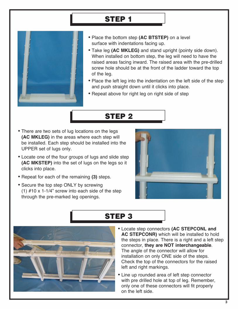
• Place the bottom step (AC BTSTEP) on a level surface with indentations facing up.
• Take leg (AC MKLEG) and stand upright (pointy side down). When installed on bottom step, the leg will need to have the raised areas facing inward. The raised area with the pre-drilled screw hole should be at the front of the ladder toward the top of the leg.
• Place the left leg into the indentation on the left side of the step and push straight down until it clicks into place.
• Repeat above for right leg on right side of step
STEP 2
• There are two sets of lug locations on the legs (AC MKLEG) in the areas where each step will be installed. Each step should be installed into the UPPER set of lugs only.
• Locate one of the four groups of lugs and slide step (AC MKSTEP) into the set of lugs on the legs so it clicks into place.
• Repeat for each of the remaining (3) steps.• Secure the top step ONLY by screwing
(1) #10 x 1-1/4” screw into each side of the step through the pre-marked leg openings.
3
STEP 3
• Locate step connectors (AC STEPCONL and AC STEPCONR) which will be installed to hold the steps in place. There is a right and a left step connector, they are NOT interchangeable. The angle of the connector will allow for installation on only ONE side of the steps. Check the top of the connectors for the raised left and right markings.
• Line up rounded area of left step connector with pre drilled hole at top of leg. Remember, only one of these connectors will fit properly on the left side.

STEP 3 CONT.
• Place washer on bolt and insert from INSIDE of ladder thru leg and step connector. Insert a second washer on end of bolt and screw on nut. Do not over tighten.
• Repeat above steps for the right step connector with the remaining bolt, washers and nut.
• To attach step connectors to steps, secure with (2) #10 x 1/4” screw through each pre-marked openings on the step connectors into steps on left and right sides, except top step.
• Once completed set this half of the ladder aside and proceed to STEP 4.
STEP 4
• Place the bottom step (AC BTSTEP) on a level surface with indentations facing up.
• Take leg (AC MKLEG) and stand upright (pointy side down). When installed on bottom step, the leg will need to have the raised areas facing inward. The raised area with the pre-drilled screw hole should be at the front of the ladder toward the top of the leg.
• Place the left leg into the indentation on the left side of the step and push straight down until it clicks into place.
• Repeat above for right leg on right side of step
NOTE STEP 4 IS SIMILAR TO STEP 1
• There are two sets of lug locations on the legs (AC MKLEG) in the areas where each step will be installed. Each step should be installed into the UPPER set of lugs only.
• Locate one of the four groups of lugs and slide step (AC MKSTEP) into the set of lugs on the legs so it clicks into place.
• Repeat for each of the remaining (3) steps.• Secure ALL STEPS by screwing (1) #10 x 1-1/4” screw into
each side of the step through the pre-marked leg openings.
NOTE No Step Connectors are used in this step
STEP 5

5
STEP 6
• Slide Upper Brace (AC 01125) over Small Barrier as shown.
• Slide Upper Brace (AC 01125) through the groove in the Large Barrier and push down lightly to secure.
• Place the Lower Base (AC 01126) on a level surface.
• Snap Large Barrier (AC 01123) into the groove on the lower base facing round edge.
• Snap Small Barrier (AC 01124) into the groove on the lower base facing the straight side.
• Screw Lower Base of Entrapment Barrier into bottom step of the Inside Portion of the Ladder with (2) #10 x 1-1/4” screws. (This is the side WITHOUT FLIP UP STEPS!)

6
• Screw Upper Brace of Entrapment Barrier into the third step of the Inside Portion of the Ladder with (2) #10 x 1-1/4” screws. (This is the side WITHOUT FLIP UP STEPS!)
STEP 7
STEP 6 CONT.
FOR 52” POOLS, CUT HANDRAIL AT THIS FIRST LINE
• This ladder is designed to fit multiple pool heights. ONLY FOLLOW THIS STEP IF YOUR POOL HEIGHT IS 52”.
• Locate the first line on the Handrail (AC 01127) of the ladder.
• Using a hacksaw cut the Handrail evenly through both sides.
52” POOLS
FOR 52” POOLS CONTINUE WITH STEP 7FOR 48” POOLS SKIP TO STEP # 8FOR 54” POOLS SKIP TO STEP # 9

7
STEP 8
• This ladder is designed to fit multiple pool heights. ONLY FOLLOW THIS STEP IF YOUR POOL HEIGHT IS 48”.
• Locate the second line on the Handrail (AC 01127) of the ladder.
• Using a hacksaw cut the Handrail evenly through both sides.
• This Ladder is designed to fit multiple pool heights. ONLY FOLLOW THIS STEP IF YOUR POOL HEIGHT IS 48”.
• Locate the leg (AC MKLEG) on both assembled sides of the ladder.
• Find the line towards the top of the leg.• Using a hacksaw cut all four (4) legs
evenly.
FOR 48” POOLS, CUT HANDRAIL AT THIS SECOND LINE
FOR 48” POOLS, CUT ALL FOUR LEGS AT THIS LINE
48” POOLS
48” POOLS

8
STEP 9
• Locate the interior portion of the ladder. This is the portion of the ladder that has the entrapment barrier attached to it.
• Using a funnel fill both legs with sand. Use approximately 20 Lbs. of sand in each leg.
• Lay one handrail (AC 01127) on a flat surface and push the connected dowels of the platform into the openings on the handrail until fully seated. Make sure treads of platform are facing upward.
• Attach the second handrail (AC 01127) to the platform the same way.
FILL LEGS WITH SAND USING A FUNNEL
STEP 10
FOR 54” POOLS NO MODIFICATIONS ARE NECESSARY

9
STEP 10 CONT.
STEP 11
• Center locking cap (AC LOCKCAP) over opening on side of handrail where platform was just attached. Using a rubber mallet or a hammer and a small piece of wood, tap on cap until the cap is flush with the Handrail.
• Repeat for each of the remaining (3) locking caps.
• Secure all handrails (AC 01127) to the legs with (4) #10 1-1/4” screws through each of the pre-marked openings.
• Coat the tops of the legs with Blue Seal O-Ring Lube or liquid soap and attach handrails by pushing them down over the legs.
TM
10
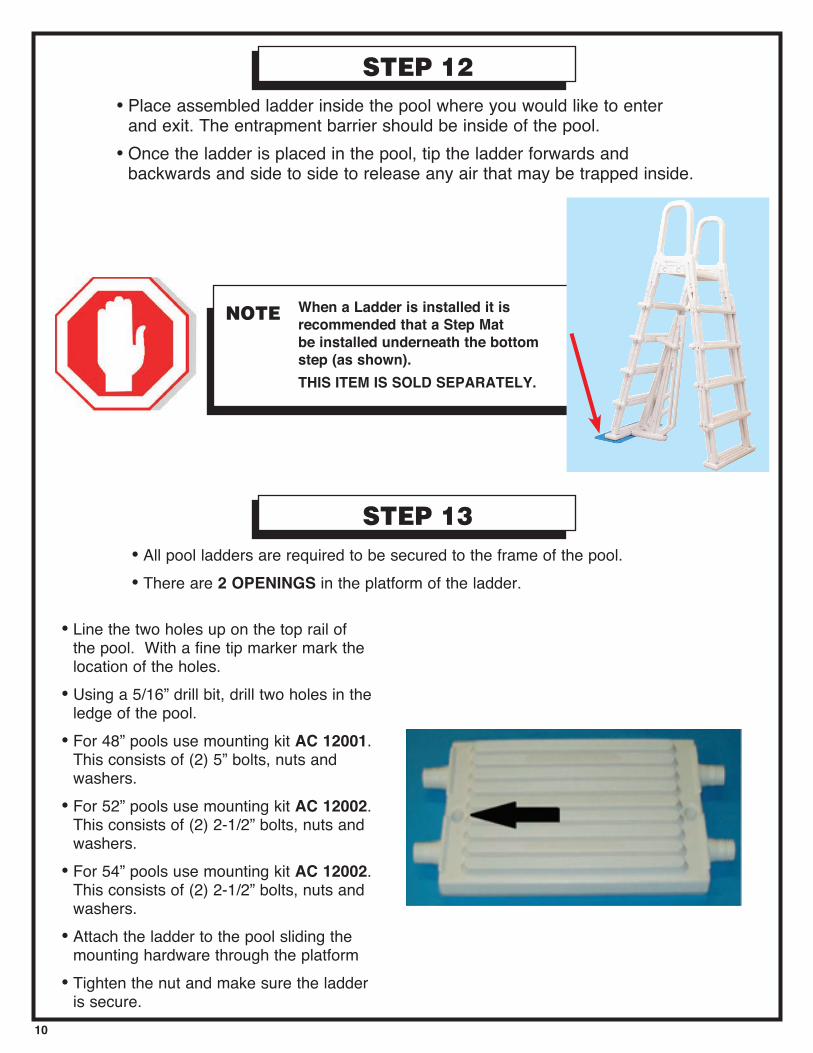
• Line the two holes up on the top rail of the pool. With a fine tip marker mark the location of the holes.
• Using a 5/16” drill bit, drill two holes in the ledge of the pool.
• For 48” pools use mounting kit AC 12001. This consists of (2) 5” bolts, nuts and washers.
• For 52” pools use mounting kit AC 12002. This consists of (2) 2-1/2” bolts, nuts and washers.
• For 54” pools use mounting kit AC 12002. This consists of (2) 2-1/2” bolts, nuts and washers.
• Attach the ladder to the pool sliding the mounting hardware through the platform
• Tighten the nut and make sure the ladder is secure.
• All pool ladders are required to be secured to the frame of the pool.• There are 2 OPENINGS in the platform of the ladder.
• Place assembled ladder inside the pool where you would like to enter and exit. The entrapment barrier should be inside of the pool.
• Once the ladder is placed in the pool, tip the ladder forwards and backwards and side to side to release any air that may be trapped inside.
STEP 13
STEP 12
NOTE When a Ladder is installed it is recommended that a Step Mat be installed underneath the bottom step (as shown).THIS ITEM IS SOLD SEPARATELY.

11
SAFETY INFORMATION
WARNINGExceeding the recommended weight limit may cause
the step to fail and may result in injury.
MAINTENANCE
• Step/ladder/bridges must be removed for winter. Failure to do so can cause the step to crack.
• When removing step/ladder/bridges for winter, it is recommended that you spray down step with hose water to rinse off any chemical residual prior to storing.
• When storing step/ladder/bridges for winter, it should be protected from the elements and stored either in a shed or garage, or covered with a tarp.
• To avoid injury when lifting heavy or awkward loads, it is suggested that two people lift the object.
• DO NOT use the pool entry system for any purpose other than that for which it is intended.
• Maximum weight on steps should NOT EXCEED 250 lbs.
LADDER SWINGS UP AND LOCKS IN PLACE
NOTE You have purchased a Flip-up Ladder. When the pool is not in use the ladder should be flipped up and locked into place by pushing down on the step portion of the ladder.


313 Regina Avenue, Rahway, NJ 07065-4891 • 732-574-1500 • info@ swimnplay.com