Embed Size (px)
Citation preview

MODEL G2790UNIVERSAL KNIFE GRINDER
OWNER'S MANUAL(For models manufactured since 04/13)
COPYRIGHT © 1992 BY GRIZZLY INDUSTRIAL, INC., REVISED MAY, 2017 (BL)WARNING: NO PORTION OF THIS MANUAL MAY BE REPRODUCED IN ANY SHAPE
OR FORM WITHOUT THE WRITTEN APPROVAL OF GRIZZLY INDUSTRIAL, INC. #0346 PRINTED IN TAIWAN
177335
V3.05.17

This manual provides critical safety instructions on the proper setup, operation, maintenance, and service of this machine/tool. Save this document, refer to it often, and use it to instruct other operators.
Failure to read, understand and follow the instructions in this manual may result in fire or serious personal injury—including amputation, electrocution, or death.
The owner of this machine/tool is solely responsible for its safe use. This responsibility includes but is not limited to proper installation in a safe environment, personnel training and usage authorization, proper inspection and maintenance, manual availability and compre-hension, application of safety devices, cutting/sanding/grinding tool integrity, and the usage of personal protective equipment.
The manufacturer will not be held liable for injury or property damage from negligence, improper training, machine modifications or misuse.
Some dust created by power sanding, sawing, grinding, drilling, and other construction activities contains chemicals known to the State of California to cause cancer, birth defects or other reproductive harm. Some examples of these chemicals are:
• Lead from lead-based paints.• Crystalline silica from bricks, cement and other masonry products.• Arsenic and chromium from chemically-treated lumber.
Your risk from these exposures varies, depending on how often you do this type of work. To reduce your exposure to these chemicals: Work in a well ventilated area, and work with approved safety equip-ment, such as those dust masks that are specially designed to filter out microscopic particles.

INTRODUCTION ............................................................................................................................... 2Manual Accuracy ........................................................................................................................ 2Contact Info ................................................................................................................................ 2Functional Overview ................................................................................................................... 2Identification ............................................................................................................................... 3Machine Data Sheet ................................................................................................................... 4
SECTION 1: SAFETY ....................................................................................................................... 6Safety Instructions for Machinery ............................................................................................... 6Additional Safety for Universal Knife Grinders ........................................................................... 8
SECTION 2: POWER SUPPLY ........................................................................................................ 9
SECTION 3: SETUP ....................................................................................................................... 11Needed for Setup ..................................................................................................................... 11Unpacking ................................................................................................................................ 11Inventory ................................................................................................................................... 12Cleanup .................................................................................................................................... 13Site Considerations .................................................................................................................. 13Mounting ................................................................................................................................... 14Assembly .................................................................................................................................. 15Test Run ................................................................................................................................... 16
SECTION 4: OPERATIONS ........................................................................................................... 17Grinding Tips ............................................................................................................................ 17Wheel Selection ....................................................................................................................... 18Wheel Care .............................................................................................................................. 18Wheel Inspection & Ring Test .................................................................................................. 19Mounting Pivot Support ............................................................................................................ 19Sharpening Narrow Tools ........................................................................................................ 20Sharpening Wide Knives .......................................................................................................... 20
SECTION 5: ACCESSORIES ......................................................................................................... 24
SECTION 6: MAINTENANCE......................................................................................................... 26Schedule .................................................................................................................................. 26Cleaning ................................................................................................................................... 26Lubrication ................................................................................................................................ 26Wheel Dressing ........................................................................................................................ 27Wheel Replacement ................................................................................................................. 28
SECTION 7: SERVICE ................................................................................................................... 29Troubleshooting ........................................................................................................................ 29
SECTION 8: WIRING ...................................................................................................................... 31Wiring Safety Instructions ........................................................................................................ 31Wiring Diagram......................................................................................................................... 32
SECTION 9: PARTS ....................................................................................................................... 33Parts Breakdown ...................................................................................................................... 33Parts List .................................................................................................................................. 34
WARRANTY AND RETURNS ........................................................................................................ 37
Table of Contents

-2- Model G2790 (Mfd. Since 04/13)
INTRODUCTION
Functional Overview
The Model G2790 is a dry grinder and is not designed to be used with cutting fluids.
This grinder is designed to sharpen cutting tools up to 20" long, such as chisels with a straight edge or jointer/planer knives, that can be securely mounted in one of the two clamping systems. The cutting tool can be positioned at angles from 15° to 90° to the grinding wheel.
Refer to Figures 1–2 for examples of typical grinding setups.
Figure 1. Example of a grinding setup for a chisel.
Figure 2. Example of grinding setup for jointer knife (shown without adjustable guard for clarity).
Manual Accuracy
We are proud to offer this document with your new machine! We've made every effort to be exact with the instructions, specifications, draw-ings, and photographs of the machine we used when writing this manual. However, sometimes we still make an occasional mistake.
Also, owing to our policy of continuous improve-ment, your machine may not exactly match the manual. If you find this to be the case, and the difference between the manual and machine leaves you in doubt, immediately call our techni-cal support for updates or clarification.
For your convenience, we post all available docu-mentation on our website at www.grizzly.com. Any updates to this document will be reflected on our website as soon as complete.
Contact Info
We stand behind our machines! If you have ques-tions or need help, contact us with the information below. Before contacting, make sure you get the serial number and manufacture date from the machine ID label. This will help us help you faster.
Grizzly Technical Support1815 W. Battlefield
Springfield, MO 65807Phone: (570) 546-9663
Email: [email protected]
We want your feedback on this manual. What did you like about it? Where could it be improved? Please take a few minutes to give us feedback.
Grizzly Documentation ManagerP.O. Box 2069
Bellingham, WA 98227-2069Email: [email protected]

Model G2790 (Mfd. Since 04/13) -3-
Identification
Figure 3. Model G2790 identification.
Knife Clamp Knob
Knife Clamp
WheelGuard
TableHandwheel
Table
GrindingWheel
SlideTable
MountingHole
Pivot SupportAdjustment Knob
TableLock
PivotSupport
KnifeAdjustment
Knob
ON/OFFSwitch
SlideBar
To reduce your risk of serious injury, read this entire manual BEFORE using machine.
Adjustable Guard

-4- Model G2790 (Mfd. Since 04/13)
Machine Data Sheet
Page 1 of 2 Model G2790
MODEL G2790UNIVERSAL KNIFE GRINDER
Product Dimensions:
Weight ............................................................................................................................................................................. 45 lbs.Length/Width/Height .......................................................................................................................................24" x 11 1⁄2" x 13"Foot Print (Length/Width) .............................................................................................................................................. 9" Circle
Shipping Dimensions:
Type ...........................................................................................................................................................................CardboardContent .......................................................................................................................................................................... MachineWeight .............................................................................................................................................................................. 59 lbs.Box 1 Length/Width/Height .................................................................................................................................20" x 13" x 13"Box 2 Length/Width/Height .....................................................................................................................................26" x 5" x 3"
Electrical:
Switch ................................................................................................................................................................ ON/OFF ToggleSwitch Voltage ................................................................................................................................................................... 110VCord Length ..........................................................................................................................................................................4 ft.Cord Gauge .................................................................................................................................................................18 gaugeMinimum Circuit Requirement .............................................................................................................................................. 15AIncluded Plug ........................................................................................................................................................... NEMA 5-15
Motor:
Type ......................................................................................................................................... TEFC Capacitor Start InductionHorsepower ........................................................................................................................................................................1⁄2 HPVoltage ............................................................................................................................................................................... 110VPhase ................................................................................................................................................................................SingleAmps ...................................................................................................................................................................................... 3ASpeed .........................................................................................................................................................................3500 RPMCycle ................................................................................................................................................................................. 60 HzPower Transfer ........................................................................................................................................................Direct DriveBearings ............................................................................................................................... Shielded and Permanently Sealed

Model G2790 (Mfd. Since 04/13) -5-Model G2790Page 2 of 2
Capacities
Maximum Blade Length ........................................................................................................................................................ 20"Table Tilt ......................................................................................................................................................................20° – 70°
Grinding Wheel Specifications:
Type .................................................................................................................................................................................Type 5Diameter .................................................................................................................................................................................. 6"Thickness ............................................................................................................................................................................. 1 1⁄2"Bore .........................................................................................................................................................................................1⁄2"
Construction:
Base .............................................................................................................................................................................Cast IronTable ............................................................................................................................................................................Cast Iron
Other Specifications:
Country of Origin ............................................................................................................................................................. TaiwanWarranty ........................................................................................................................................................................... 1 YearSerial Number Location ................................................................................................................... ID Label on Front of MotorApproximate Assembly/Setup Time .......................................................................................................................... 15 Minutes
Features:
Knife Holder Adjusts From 20° – 70°120 Grit Aluminum Oxide Grinding Stone Raises and Lowers

-6- Model G2790 (Mfd. Since 04/13)
ELECTRICAL EQUIPMENT INJURY RISKS. You can be shocked, burned, or killed by touching live electrical components or improperly grounded machinery. To reduce this risk, only allow qualified service personnel to do electrical installation or repair work, and always disconnect power before accessing or exposing electrical equipment.
DISCONNECT POWER FIRST. Always discon-nect machine from power supply BEFORE making adjustments, changing tooling, or servicing machine. This prevents an injury risk from unintended startup or contact with live electrical components.
EYE PROTECTION. Always wear ANSI-approved safety glasses or a face shield when operating or observing machinery to reduce the risk of eye injury or blindness from flying particles. Everyday eyeglasses are NOT approved safety glasses.
OWNER’S MANUAL. Read and understand this owner’s manual BEFORE using machine.
TRAINED OPERATORS ONLY. Untrained oper-ators have a higher risk of being hurt or killed. Only allow trained/supervised people to use this machine. When machine is not being used, dis-connect power, remove switch keys, or lock-out machine to prevent unauthorized use—especially around children. Make your workshop kid proof!
DANGEROUS ENVIRONMENTS. Do not use machinery in areas that are wet, cluttered, or have poor lighting. Operating machinery in these areas greatly increases the risk of accidents and injury.
MENTAL ALERTNESS REQUIRED. Full mental alertness is required for safe operation of machin-ery. Never operate under the influence of drugs or alcohol, when tired, or when distracted.
For Your Own Safety, Read Instruction Manual Before Operating This Machine
The purpose of safety symbols is to attract your attention to possible hazardous conditions. This manual uses a series of symbols and signal words intended to convey the level of impor-tance of the safety messages. The progression of symbols is described below. Remember that safety messages by themselves do not eliminate danger and are not a substitute for proper accident prevention measures. Always use common sense and good judgment.
Indicates a potentially hazardous situation which, if not avoided, MAY result in minor or moderate injury. It may also be used to alert against unsafe practices.
Indicates a potentially hazardous situation which, if not avoided, COULD result in death or serious injury.
Indicates an imminently hazardous situation which, if not avoided, WILL result in death or serious injury.
This symbol is used to alert the user to useful information about proper operation of the machine.NOTICE
Safety Instructions for Machinery
SECTION 1: SAFETY

Model G2790 (Mfd. Since 04/13) -7-
WEARING PROPER APPAREL. Do not wear clothing, apparel or jewelry that can become entangled in moving parts. Always tie back or cover long hair. Wear non-slip footwear to reduce risk of slipping and losing control or accidentally contacting cutting tool or moving parts.
HAZARDOUS DUST. Dust created by machinery operations may cause cancer, birth defects, or long-term respiratory damage. Be aware of dust hazards associated with each workpiece mate-rial. Always wear a NIOSH-approved respirator to reduce your risk.
HEARING PROTECTION. Always wear hear-ing protection when operating or observing loud machinery. Extended exposure to this noise without hearing protection can cause permanent hearing loss.
REMOVE ADJUSTING TOOLS. Tools left on machinery can become dangerous projectiles upon startup. Never leave chuck keys, wrenches, or any other tools on machine. Always verify removal before starting!
USE CORRECT TOOL FOR THE JOB. Only use this tool for its intended purpose—do not force it or an attachment to do a job for which it was not designed. Never make unapproved modifica-tions—modifying tool or using it differently than intended may result in malfunction or mechanical failure that can lead to personal injury or death!
AWKWARD POSITIONS. Keep proper footing and balance at all times when operating machine. Do not overreach! Avoid awkward hand positions that make workpiece control difficult or increase the risk of accidental injury.
CHILDREN & BYSTANDERS. Keep children and bystanders at a safe distance from the work area.Stop using machine if they become a distraction.
GUARDS & COVERS. Guards and covers reduce accidental contact with moving parts or flying debris. Make sure they are properly installed, undamaged, and working correctly BEFORE operating machine.
FORCING MACHINERY. Do not force machine. It will do the job safer and better at the rate for which it was designed.
NEVER STAND ON MACHINE. Serious injury may occur if machine is tipped or if the cutting tool is unintentionally contacted.
STABLE MACHINE. Unexpected movement dur-ing operation greatly increases risk of injury or loss of control. Before starting, verify machine is stable and mobile base (if used) is locked.
USE RECOMMENDED ACCESSORIES. Consult this owner’s manual or the manufacturer for rec-ommended accessories. Using improper acces-sories will increase the risk of serious injury.
UNATTENDED OPERATION. To reduce the risk of accidental injury, turn machine OFF and ensure all moving parts completely stop before walking away. Never leave machine running while unattended.
MAINTAIN WITH CARE. Follow all maintenance instructions and lubrication schedules to keep machine in good working condition. A machine that is improperly maintained could malfunction, leading to serious personal injury or death.
DAMAGED PARTS. Regularly inspect machine for damaged, loose, or mis-adjusted parts—or any condition that could affect safe operation. Immediately repair/replace BEFORE operating machine. For your own safety, DO NOT operate machine with damaged parts!
MAINTAIN POWER CORDS. When disconnect-ing cord-connected machines from power, grab and pull the plug—NOT the cord. Pulling the cord may damage the wires inside. Do not handle cord/plug with wet hands. Avoid cord damage by keeping it away from heated surfaces, high traffic areas, harsh chemicals, and wet/damp locations.
EXPERIENCING DIFFICULTIES. If at any time you experience difficulties performing the intend-ed operation, stop using the machine! Contact our Technical Support at (570) 546-9663.

-8- Model G2790 (Mfd. Since 04/13)
Additional Safety for Universal Knife Grinders
Serious injury or death can occur from impact injuries. Rotating grinding wheels can easily remove skin, or entanglement/amputation injuries can occur from being caught in moving parts or in-running pinch points. Flying sparks can ignite explosive or flammable materials. To minimize risk of getting hurt or killed, anyone operating machine MUST completely heed hazards and warnings below.
EYE PROTECTION. Grinding causes small par-ticles to become airborne at a high rate of speed. ALWAYS wear safety glasses or face shield when using this machine.
MOUNTING TO WORKBENCH. An unsecured grinder may become dangerously out of con-trol during operation. Make sure the grinder is FIRMLY secured to the workbench.
WHEEL SPEED RATING. Wheels operated at a faster speed than they are rated for may fly apart during use. Before mounting a new wheel, be sure the wheel RPM rating is equal to or higher than the speed of the grinder—3500 RPM.
WHEEL FLANGES. When mounting wheels only use the wheel flanges that are included with this grinder. Other flanges may not properly secure the wheel and will increase the risk of the wheel flying apart during operation.
WHEEL INSPECTION. Visually inspect the wheel and perform the “ring test” before installation to ensure that it is safe to use. A wheel that does not pass the ring test may fly apart during opera-tion—DO NOT use it!
DRY GRINDING. This grinder is not designed to work with cutting fluids. DO NOT use cutting flu-ids, and keep all liquids away from the grinder to reduce the risk of electrocution.
STARTING GRINDER. If a grinding wheel is damaged, it will usually fly apart shortly after start-up. Never start the grinder with the wheel above the surface of the grinder table. Stand clear of the grinder after starting it and wait for at least one minute before standing in front of it.
LUNG PROTECTION. Grinding produces hazard-ous dust, which may cause long-term respiratory problems if breathed. ALWAYS wear a NIOSH- approved dust mask or respirator when grinding.
HAND/WHEEL CONTACT. Grinding wheels have the capability of removing a lot of skin quickly. Keep a firm grip on the tool or slide bar and posi-tion your hands at a safe distance away from the wheel when grinding. Do not wear gloves when grinding as they may get caught in the wheel and cause serious entanglement injuries.
GUARDS & SUPPORTS. Always keep the wheel guard secured in place when operating the grind-er. Always keep the cutting tool firmly clamped before starting the machine. Correctly position and lock the pivot support before turning the grinder ON.
EXPERIENCING DIFFICULTIES. If at any time you are experiencing difficulties performing the intended operation, stop using the machine and contact Tech Support at (570) 546-9663.

Model G2790 (Mfd. Since 04/13) -9-
SECTION 2: POWER SUPPLY
AvailabilityBefore installing the machine, consider the avail-ability and proximity of the required power supply circuit. If an existing circuit does not meet the requirements for this machine, a new circuit must be installed. To minimize the risk of electrocution, fire, or equipment damage, installation work and electrical wiring must be done by an electrician or qualified service personnel in accordance with all applicable codes and standards.
Electrocution, fire, shock, or equipment damage may occur if machine is not properly grounded and connected to power supply.
Full-Load Current RatingThe full-load current rating is the amperage a machine draws at 100% of the rated output power. On machines with multiple motors, this is the amperage drawn by the largest motor or sum of all motors and electrical devices that might operate at one time during normal operations.
Full-Load Current Rating at 110V .................3A
The full-load current is not the maximum amount of amps that the machine will draw. If the machine is overloaded, it will draw additional amps beyond the full-load rating.
If the machine is overloaded for a sufficient length of time, damage, overheating, or fire may result—especially if connected to an undersized circuit. To reduce the risk of these hazards, avoid over-loading the machine during operation and make sure it is connected to a power supply circuit that meets the specified circuit requirements.
For your own safety and protection of property, consult an electrician if you are unsure about wiring practices or electrical codes in your area.
Note: Circuit requirements in this manual apply to a dedicated circuit—where only one machine will be running on the circuit at a time. If machine will be connected to a shared circuit where multiple machines may be running at the same time, con-sult an electrician or qualified service personnel to ensure circuit is properly sized for safe operation.
A power supply circuit includes all electrical equipment between the breaker box or fuse panel in the building and the machine. The power sup-ply circuit used for this machine must be sized to safely handle the full-load current drawn from the machine for an extended period of time. (If this machine is connected to a circuit protected by fuses, use a time delay fuse marked D.)
110V Circuit RequirementsThis machine is prewired to operate on a power supply circuit that has a verified ground and meets the following requirements:
Nominal Voltage ........................................ 110VCycle ..........................................................60 HzPhase ........................................... Single-PhasePower Supply Circuit ..................................15A
Serious injury could occur if you connect machine to power before completing setup process. DO NOT connect to power until instructed later in this manual.

-10- Model G2790 (Mfd. Since 04/13)
Improper connection of the equipment-grounding wire can result in a risk of electric shock. The wire with green insulation (with or without yellow stripes) is the equipment-grounding wire. If repair or replacement of the power cord or plug is nec-essary, do not connect the equipment-grounding wire to a live (current carrying) terminal. Check with a qualified electrician or service per-sonnel if you do not understand these grounding requirements, or if you are in doubt about whether the tool is properly grounded. If you ever notice that a cord or plug is damaged or worn, discon-nect it from power, and immediately replace it with a new one.
Extension CordsWe do not recommend using an extension cord with this machine. If you must use an extension cord, only use it if absolutely necessary and only on a temporary basis.
Extension cords cause voltage drop, which can damage electrical components and shorten motor life. Voltage drop increases as the extension cord size gets longer and the gauge size gets smaller (higher gauge numbers indicate smaller sizes).
Any extension cord used with this machine must be in good condition and contain a ground wire and matching plug/receptacle. Additionally, it must meet the following size requirements:
Minimum Gauge Size ...........................16 AWGMaximum Length (Shorter is Better).......50 ft.
Grounding & Plug Requirements
Figure 4. Typical 5-15 plug and receptacle.
Grounding Prong
Neutral Hot
5-15 PLUG
GROUNDED5-15 RECEPTACLE
SHOCK HAZARD!Two-prong outlets do not meet the grounding requirements for this machine. Do not modify or use an adapter on the plug provided—if it will not fit the outlet, have a qualified electrician install the proper outlet with a verified ground.
This machine MUST be grounded. In the event of certain malfunctions or breakdowns, grounding reduces the risk of electric shock by providing a path of least resistance for electric current.
This machine is equipped with a power cord that has an equipment-grounding wire and a grounding plug. Only insert plug into a matching receptacle (outlet) that is properly installed and grounded in accordance with all local codes and ordinances. DO NOT modify the provided plug!

Model G2790 (Mfd. Since 04/13) -11-
SECTION 3: SETUP
This machine was carefully packaged for safe transport. When unpacking, separate all enclosed items from packaging materials and inspect them for shipping damage. If items are damaged, please call us immediately at (570) 546-9663.
IMPORTANT: Save all packaging materials until you are completely satisfied with the machine and have resolved any issues between Grizzly or the shipping agent. You MUST have the original pack-aging to file a freight claim. It is also extremely helpful if you need to return your machine later.
Unpacking
SUFFOCATION HAZARD!Keep children and pets away from plastic bags or packing materials shipped with this machine. Discard immediately.
This machine presents serious injury hazards to untrained users. Read through this entire manu-al to become familiar with the controls and opera-tions before starting the machine!
Wear safety glasses during the entire setup process!
Needed for Setup
The following items are needed, but not included, for the setup/assembly of this machine.
Description Qty• Rags & Solvent ........................... As Needed• Mounting Hardware (Page 14) ... As Needed• Open-End Wrench 12mm ........................... 1• Hex Wrench 4mm ....................................... 1

-12- Model G2790 (Mfd. Since 04/13)
Box 1 Contents (Figure 5) QtyA. Grinding Assembly w/Pivot Support ........... 1B. Wheel Dressing Stone ............................... 1C. Wheel Dressing Tool Holder ...................... 1D. Star Knobs 1⁄4"-20 x 1⁄2"............................... 2E. Flat Washers 1⁄4" ......................................... 2F. Adjustable Guard ........................................ 1G. Star Knobs 1⁄4"-20 x 23⁄4" ............................. 5H. Star Knobs 1⁄4"-20 x 7⁄8" ............................... 5I. O-Rings 6 x 2mm ....................................... 5J. Hex Nuts 1⁄4"-20 .......................................... 5
Box 2 Contents (Figure 6) QtyK. Slide Table .................................................. 1L. Slide Bar ..................................................... 1M. Knife Clamp ................................................ 1
Figure 5. Box 1 inventory.
A
B C
D E F
G H
I J
K
L
MNOTICEIf you cannot find an item on this list, care-fully check around/inside the machine and packaging materials. Often, these items get lost in packaging materials while unpack-ing or they are pre-installed at the factory.
Inventory
The following is a list of items shipped with your machine. Before beginning setup, lay these items out and inventory them.
If any non-proprietary parts are missing (e.g. a nut or a washer), we will gladly replace them; or for the sake of expediency, replacements can be obtained at your local hardware store.
Figure 6. Box 2 inventory.

Model G2790 (Mfd. Since 04/13) -13-
Cleanup
The unpainted surfaces of your machine are coated with a heavy-duty rust preventative that prevents corrosion during shipment and storage. This rust preventative works extremely well, but it will take a little time to clean.
Be patient and do a thorough job cleaning your machine. The time you spend doing this now will give you a better appreciation for the proper care of your machine's unpainted surfaces.
There are many ways to remove this rust preven-tative, but the following steps work well in a wide variety of situations. Always follow the manufac-turer’s instructions with any cleaning product you use and make sure you work in a well-ventilated area to minimize exposure to toxic fumes.
Before cleaning, gather the following:• Disposable rags• Cleaner/degreaser (WD•40 works well)• Safety glasses & disposable gloves• Plastic paint scraper (optional)
Basic steps for removing rust preventative:
1. Put on safety glasses.
2. Coat the rust preventative with a liberal amount of cleaner/degreaser, then let it soak for 5–10 minutes.
3. Wipe off the surfaces. If your cleaner/degreas-er is effective, the rust preventative will wipe off easily. If you have a plastic paint scraper, scrape off as much as you can first, then wipe off the rest with the rag.
4. Repeat Steps 2–3 as necessary until clean, then coat all unpainted surfaces with a quality metal protectant to prevent rust.
NOTICEAvoid chlorine-based solvents, such as acetone or brake parts cleaner, that may damage painted surfaces.
Figure 7. Minimum working clearances.
44"
10"12"
Site Considerations
Children and visitors may be seriously injured if unsuper-vised around this machine. Lock entrances to the shop or disable start switch or power connection to prevent unsupervised use.
Workbench LoadRefer to the Machine Data Sheet for the weight and footprint specifications of your machine. Some workbenches may require additional rein-forcement to support the weight of the machine and workpiece materials.
Consider anticipated workpiece sizes and addi-tional space needed for auxiliary stands, work tables, or other machinery when establishing a location for this machine in the shop. Below is the minimum amount of space needed for the machine.
Placement Location

-14- Model G2790 (Mfd. Since 04/13)
Mounting
The vibration and forces applied during operation could cause the grinder to unexpectedly move and greatly increase the risk of serious personal injury. You MUST firmly mount your grinder to a stable and flat surface that will not move during operation.
Note: The rubber feet provide vibration absorp-tion for the grinder. We recommend that you keep them on the machine when you mount it to the workbench.
Figure 8. Example of a through mount setup.
The base of this machine has mounting holes that allow it to be fastened to a workbench or other mounting surface to prevent it from moving during operation and causing accidental injury or damage.
The strongest mounting option is a "Through Mount" (see example below) where holes are drilled all the way through the workbench—and hex bolts, washers, and hex nuts are used to secure the machine in place.
Machine Base
Workbench
HexBolt
Flat Washer
Flat Washer Lock Washer
Hex Nut
Number of Mounting Holes ............................ 2Diameter of Mounting Hardware Needed .. 1⁄2"
Figure 9. Example of a direct mount setup.
Machine Base
Workbench
Lag Screw
Flat Washer
Another option is a "direct mount" (see example below) where the machine is secured directly to the workbench with lag screws and washers.

Model G2790 (Mfd. Since 04/13) -15-
Assembly
The machine must be fully assembled before it can be operated. Before beginning the assembly process, refer to Needed for Setup and gather all listed items. To ensure the assembly process goes smoothly, first clean any parts that are cov-ered or coated in heavy-duty rust preventative (if applicable).
To assemble your machine:
1. Install adjustable guard on pre-installed wheel guard using (2) 1⁄4"-20 x 1⁄2" star knobs and (2) 1⁄4" flat washers, as shown in Figure 10.
Figure 10. Adjustable guard installed (slide bar, knife clamp installed for illustration purposes).
Star Knobs w/Flat Washers
AdjustableGuard
2. Loosen star knobs, position adjustable guard approximately 1⁄8" away from knife clamp or stationary clamp, then tighten star knobs to secure setting (see Figure 11). Refer to Page 20 or Page 22 for detailed instructions on installing the stationary clamps and knife clamp.
The adjustable guard reduces the risk of injury by shielding the user from flying sparks/debris and preventing fingers from contacting the grind-ing wheel during operation. Once you install the guard, you will need to adjust it according to the needs of your operation.
Figure 11. Adjustable guard adjusted to approximately 1⁄8" from knife clamp.
1⁄8" Gap Between Adjustable Guardand Knife Clamp
3. If necessary, adjustable guard may also be set up at an angle to the wheel guard (see Figure 12).
Figure 12. Adjustable guard alternate setup (knife clamp removed for illustration purposes).
Wheel Guard

-16- Model G2790 (Mfd. Since 04/13)
Test Run To test run machine:
1. Clear all setup tools away from machine.
2. Connect machine to power supply.
3. Turn machine ON.
Listen to and watch for abnormal noises or actions. The machine should run smoothly with little or no vibration or rubbing noises.
— Strange or unusual noises should be inves-tigated and corrected before operating the machine further. Always disconnect the machine from power when investigating or correcting potential problems.
4. Turn machine OFF.
Once assembly is complete, test run the machine to ensure it is properly connected to power and safety components are functioning correctly.
If you find an unusual problem during the test run, immediately stop the machine, disconnect it from power, and fix the problem BEFORE operating the machine again. The Troubleshooting table in the SERVICE section of this manual can help.
DO NOT start machine until all preceding setup instructions have been performed. Operating an improperly set up machine may result in malfunction or unexpect-ed results that can lead to serious injury, death, or machine/property damage.
Serious injury or death can result from using this machine BEFORE understanding its controls and related safety information. DO NOT operate, or allow others to operate, machine until the information is understood.

Model G2790 (Mfd. Since 04/13) -17-
SECTION 4: OPERATIONS
Grinding Tips
The grinder is a safe tool when used properly. In addition to the safety instructions in this manual, the most important safety consideration is to use common sense at all times.
Follow these rules when grinding:
• Make sure the wheel guard and blade sup-ports are correctly mounted and secure.
• Remember that grinding often produces sparks. DO NOT allow anyone to stand in the path of the sparks without protective clothing and equipment. DO NOT grind near flam-mable materials.
• Maintain proper care of your wheels. Refer to Wheel Care on Page 18 for detailed instruc-tions.
• Wear the proper protective clothing. Particles flying from the grinding wheel are traveling at a high rate of speed—prepare for this! Wear safety glasses/face shield, a NIOSH approved dust mask or respirator, ear pro-tection, a leather apron, and heavy leather boots.
• Grasp the workpiece or support firmly. Maintain even pressure and control of the workpiece, especially when using the slide bar.
• To avoid overheating the tool, grind the cut-ting tool with multiple light passes instead of one heavy operation.
• Concentrate on the task at hand. STOP grinding if other people are distracting you or your mind is on something else.
• To some, correctly grinding cutting tools is an art. If you are not familiar with this process, get help from an experienced person or read books to become familiar with the correct procedures required to sharpen your tools.
To reduce your risk of serious injury, read this entire manual BEFORE using machine.
Eye injuries, respiratory problems, or hear-ing loss can occur while operating this tool. Wear personal protective equipment to reduce your risk from these hazards.
If you are not experienced with this type of machine, WE STRONGLY RECOMMEND that you seek additional training outside of this manual. Read books/magazines or get formal training before beginning any proj-ects. Regardless of the content in this sec-tion, Grizzly Industrial will not be held liable for accidents caused by lack of training.
Keep hair, clothing, and jewelry away from mov-ing parts at all times. Entanglement can result in death, amputation, or severe crushing injuries!

-18- Model G2790 (Mfd. Since 04/13)
Wheel Selection
Your Model G2790 uses only Type 5 grinding wheels that have a 1⁄2" bore and are 6" in diameter and 1 1⁄2" thick, similar to the one included with your grinder. Refer to Accessories on Page 24 for options from Grizzly.
Aluminum oxide and silicon carbide wheels are typically marked in a uniform manner by all major manufacturers. Understanding these markings will help you understand the capabilities of vari-ous wheels.
The typical format for wheel numbering is:
TypeAbrasive
TypeGrit Size
GradeBondType
5 A 100 K V
• Type: Refers to a particular wheel configura-tion, such as Type 5, which has a recessed center for the top-mounting flange.
• Abrasive Type: Refers to the abrasive grain of the wheel. The most common types are A for aluminum oxide, C for silicon carbide, and SG for seeded gel.
• Grit Size: Refers to the size of the abrasive grain in the wheel. The lower the number, the coarser the wheel.
• Grade: Indicates the hardness of the wheel with A being the softest and Z being the hard-est.
• Bond Type: Refers to the type of bonding material used to hold the abrasive grain. Most general-purpose wheels will have a V, indicating vitrified clay, which provides high strength and good porosity. The other common bond type is B for synthetic resins, which are generally used to grind cemented carbide and ceramic materials.
Note: There may be other numbers or letters that have meaning for a particular type of wheel. Always refer to the manufacturer's technical data for a complete explanation when choosing a grinding wheel.
Wheel Care
Your safety when grinding depends, in a large part, on the condition of the wheel during opera-tion. A wheel in poor condition increases the risk of it flying apart while spinning and injuring the operator or causing property damage.
Follow these rules to reduce the risk of break-ing the wheel:
• Always transport, store, and handle wheels with care. Wheels could be damaged if they are dropped or if heavy objects are stacked on them.
• Select the right grinding wheel for the job. DO NOT grind materials that are not correct for the wheel type.
• Select the right grinding wheel for the machine. If a grinding wheel rotates faster than its RPM rating, it could fly apart during operation.
• Mount the wheels properly (refer to Wheel Replacement on Page 28 for detailed instruc-tions). Never use a wheel with the wrong bore size for the machine.
• Do not abuse the wheel by jamming the work into the grinding wheel with excessive force or by allowing the workpiece to become overly hot during operation.
• Do not store wheels in a damp or wet location that will damage the bonding material.
• Replace the wheel when it becomes less than 1⁄2 of its original thickness or less than 3⁄4".
• Use only the wheel flanges that are included with for your grinder.
• To ensure good grinding results, dress the wheel often (refer to Wheel Dressing on Page 27 for detailed instructions).
• Always visually inspect and perform the ring test before installing any grinding wheel (refer to Wheel Inspection & Ring Test on Page 19 for detailed instructions).

Model G2790 (Mfd. Since 04/13) -19-
Wheel Inspection & Ring Test
Do not assume that a grinding wheel is in sound condition just because it is new or looks okay. Often damage can occur in shipping, with age, or with exposure to moisture, and may not be visible. Inspect every wheel for damage before installation.
First, do a visual inspection. Look for any cracks, chips, nicks or dents in the surface of the wheel. If you see any of these, DO NOT use the wheel.
Second, do a ring test. This test will give you an indication of any internal damage that may not be obvious during a visual inspection. If the wheel does not pass the ring test, DO NOT use the wheel.
To perform a ring test:
1. Make sure the wheel that you test is clean and dry—otherwise, you may get false results.
2. If size permits, balance the wheel with your finger in the center hole. If this is not possible, hang the wheel in the air with a piece of cord or string looped through the center hole.
3. At the four spots on the wheel shown in Figure 13, gently tap the wheel with a non-metallic object, such as a screwdriver handle or wooden mallet.
Figure 13. Tapping locations for a ring test.
4. An undamaged wheel will emit a clear metal-lic ring or “ping” sound in each of the four spots. A damaged wheel will respond with a dull thud that has no clear tone.
— If you determine from the results of the ring test that the wheel is damaged, DO NOT use it!
Mounting Pivot Support
The pivot support is used to hold the stationary clamps for narrow tools and the slide table and bar for wide knives.
To mount the pivot support on the grinder table:
1. DISCONNECT MACHINE FROM POWER!
2. Loosen the four lock knobs on the sides of the pivot support, then slide the support flanges onto the table, as shown in Figure 14.
3. Use the knurled wheel of the pivot gear to set the correct angle for your operation, then tighten all four lock knobs.
Figure 14. Pivot support installed.
LockKnob
Pivot Gears
Pivot Support
Flange

-20- Model G2790 (Mfd. Since 04/13)
Sharpening Narrow Tools
The stationary clamps mounted on the pivot sup-port hold tools with narrow cutting widths, such as chisels, that have a beveled edge which can be squarely aligned with the flat of the wheel, as shown in Figure 15.
To sharpen a narrow tool bevel:
1. DISCONNECT MACHINE FROM POWER!
2. Install the pivot support onto the grinder table with the two stationary clamps attached.
3. Center the tool on the pivot support between the clamps, slide them together to firmly hold the tool, then tighten their knobs to secure them in place, as shown in Figure 15.
4. Loosen the table lock, then use the table handwheel to lower the grinder table until the top surface of the wheel is even with the table.
5. Adjust the angle of the pivot support and its position on the table and in the clamps so that the tool bevel just makes contact with the wheel, as shown in Figure 15, then make sure the stationary clamps and four pivot sup-port lock knobs are tight.
6. Once you are satisfied with the position of the tool relative to the wheel, raise the grinder table slightly above the wheel, then turn the grinder ON.
7. While firmly holding the tool on the pivot sup-port, slowly and carefully lower the grinder table until the tool contacts the wheel to begin sharpening the tool.
Note: Keep in mind that with a dry grinding operation, tools can heat up quickly and lose their temper. Sharpening should be done in light passes and for short durations to avoid damaging the tool or wheel.
Tip: Apply marker ink to the full beveled sur-face of the tool to help verify when the tool is properly ground. Also, a fine straightedge held to the bevel will show any variations.
Cutting tools are dangerously sharp, espe-cially after sharpening. Use extreme caution when handling these tools to reduce the risk of personal injury.
Sharpening Wide Knives
Wide knives, such as jointer and planer blades, are firmly held in the slide bar assembly that is then mounted on the slide table above the wheel.
Tools Needed QtyWrench 10mm ................................................... 1Wrench or Socket 12mm ................................... 1Fine Ruler .......................................................... 1
To sharpen wide knives:
1. DISCONNECT MACHINE FROM POWER!
2. Remove the adjustable guard.
Figure 15. Stationary clamps holding a narrow tool.
Stationary Clamp

Model G2790 (Mfd. Since 04/13) -21-
5. Re-attach the pivot support to the grinder table so that the flat surface of the slide table is facing the wheel, as shown in Figure 18.
Figure 18. Pivot support and slide table assembly properly attached to the grinder.
Cutting tools are dangerously sharp, espe-cially after sharpening. Use extreme caution when handling these tools to reduce the risk of personal injury.
3. Then place the slide table on a flat surface and remove the three hex bolts and flat wash-ers, as shown in Figure 16.
4. Remove the pivot support from the machine, then secure it to the back of the slide table with the three hex nuts and flat washers removed in Step 3, as shown in Figure 17.
Figure 16. Slide table dismantled.
Slide Table
Hex Bolts & Flat
Washers
Figure 17. Pivot support attached to the slide table.
Pivot Support
6. Install (5) 1⁄4"-20 x 23⁄4" knife adjustment knobs on the slide bar, each with (1) O-ring and (1) 1⁄4"-20 hex nut. Then back the adjust-ment knobs out enough so that the knife can be positioned in the middle of the slide bar and even with its front edge, as shown in Figure 19.
Figure 19. Wide knife placed on the slide bar even with the front edge.
Wide Knife
O-Ring Hex Nut1⁄4"-20 x 23⁄4"Knife Adjustment
Knob

-22- Model G2790 (Mfd. Since 04/13)
A wide knife must be centered on the slide bar and be supported by at least two adjust-ment knobs to reduce the risk of the knife coming loose during operation and causing personal injury or property damage.
7. Using a fine ruler, tighten the adjustment knobs to force the knife forward so that it extends beyond the front edge of the slide bar approximately 1⁄4" along its full length, as shown in Figure 20.
Note: The distance the knife extends beyond the slide bar may vary depending on the angle required to grind the bevel. However, make sure the slide bar will not make contact with the grinding wheel during operation to prevent damaging the bar.
Figure 20. Extending the knife beyond the front edge of the slide bar.
8. When you are satisfied that the knife extends beyond the slide bar the same amount along its length and that the supporting adjustment knobs are all making even contact with the back of the knife, re-tighten the jam nuts and attach the knife clamp to the slide bar with (5) 1⁄4"-20 x 7⁄8" knife clamp knobs, as shown in Figure 21.
9. Use the fine ruler to re-check the distance the knife extends from the slide bar.
— If the distance is not correct or the same along the full length of the knife, slightly loosen the knife clamp knobs and adjust the knife adjustment knobs until the extended distance is correct. Then, re-tighten the jam nuts and knife clamp knobs and check the distance again. If necessary, repeat this process until the distance is correct and the knife is securely clamped.
Figure 21. Knife clamped to the slide bar.
Knife
Knife Clamp
1⁄4"-20 x 7⁄8"Knife Clamp
Knob
Model G2790 (Mfd. Since 04/13) -23-
10. Carefully place the slide bar assembly on the slide table, as shown in Figure 22, loosen the table lock, then lower the grinder table until the wheel just makes contact with the knife.
Note: Make sure the grinder table and the top wheel surface are level with each other. You may have to push down or pull up on one side of the grinder table to make them level with each other.
Figure 22. Slide bar assembly and knife mounted on the grinder.
— If the wheel does not move evenly when the knife slides across it from one end to the other, either the knife is not evenly mounted in the slide bar or the surface of the wheel is not level with the grinder table. To ensure good grinding results, you must make the knife bevel level and paral-lel with the wheel surface along its entire length before continuing with this proce-dure. Refer to the Troubleshooting chart on Page 29 for possible solutions.
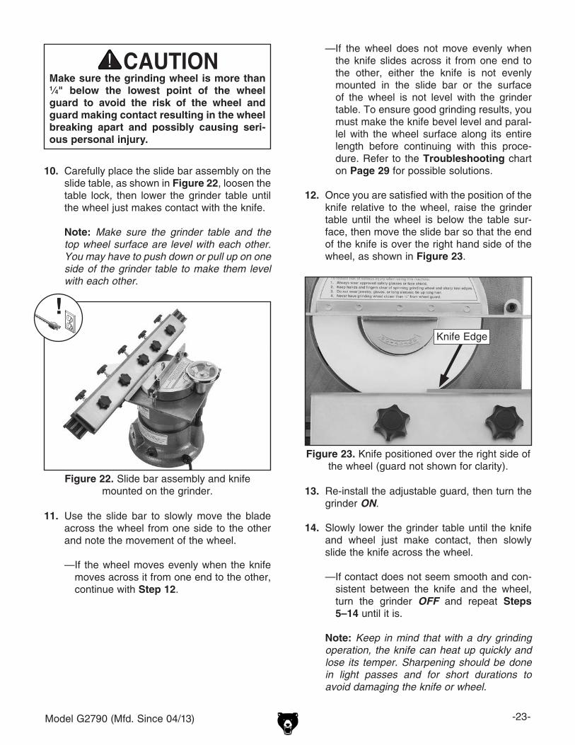
12. Once you are satisfied with the position of the knife relative to the wheel, raise the grinder table until the wheel is below the table sur-face, then move the slide bar so that the end of the knife is over the right hand side of the wheel, as shown in Figure 23.
13. Re-install the adjustable guard, then turn the grinder ON.
14. Slowly lower the grinder table until the knife and wheel just make contact, then slowly slide the knife across the wheel.
— If contact does not seem smooth and con-sistent between the knife and the wheel, turn the grinder OFF and repeat Steps 5–14 until it is.
Note: Keep in mind that with a dry grinding operation, the knife can heat up quickly and lose its temper. Sharpening should be done in light passes and for short durations to avoid damaging the knife or wheel.
11. Use the slide bar to slowly move the blade across the wheel from one side to the other and note the movement of the wheel.
— If the wheel moves evenly when the knife moves across it from one end to the other, continue with Step 12.
Figure 23. Knife positioned over the right side of the wheel (guard not shown for clarity).
Knife Edge
Make sure the grinding wheel is more than 1⁄4" below the lowest point of the wheel guard to avoid the risk of the wheel and guard making contact resulting in the wheel breaking apart and possibly causing seri-ous personal injury.

-24- Model G2790 (Mfd. Since 04/13)
SECTION 5: ACCESSORIESACCESSORIES
G7416—Type 5 Grinding Wheel, 120 GritG7417—Type 5 Grinding Wheel, 180 GritG7418—Type 5 Grinding Wheel, 220 GritG7419—Type 5 Grinding Wheel, 320 GritAluminum oxide abrasive grain, 6" x 1 1⁄2", 1⁄2" bore.
Figure 24. Type 5 aluminum oxide grinding wheel.
T20502—Face Shield Crown Protector 7"T20503—Face Shield WindowT20451—"Kirova" Clear Safety GlassesT20452—"Kirova" Anti-Reflective GlassesH7194—Bifocal Safety Glasses 1.5H0736—Shop Fox® Safety GlassesThese glasses meet ANSI Z87.1-2003 specifica-tions. Buy extras for visitors or employees. You can't be too careful with shop safety!
Figure 26. Our most popular eye protection.
T20451
H0736
T20452T20502
T20503
H7194
H2499—Small Half-Mask RespiratorH3631—Medium Half-Mask RespiratorH3632—Large Half-Mask RespiratorH3635—Cartridge Filter Pair P100Wood dust has been linked to nasal cancer and severe respiratory illnesses. If you work around dust everyday, a half-mask respirator can be a lifesaver. Also compatible with safety glasses!
Figure 25. Half-mask respirator with disposable cartridge filters.
order online at www.grizzly.com or call 1-800-523-4777
Installing unapproved accessories may cause machine to malfunction, resulting in serious personal injury or machine damage. To reduce this risk, only install accessories recommended for this machine by Grizzly.
NOTICERefer to our website or latest catalog for additional recommended accessories.

Model G2790 (Mfd. Since 04/13) -25-
G3092—Diamond Dresser ToolIndustrial diamond dresser tool made especially for dressing the wheels of the G2790 Universal Knife Grinder. Comes with plastic case and pro-tective rubber end cap.
Figure 28. G3092 diamond dresser tool.
order online at www.grizzly.com or call 1-800-523-4777
Model H5944—#0 Wheel DresserModel H5945—#1 Wheel DresserModel H5946—#2 Wheel DresserExposes new grains for aggressive cutting on all types of grinding wheels. Star wheels and discs are hardened steel. Cast iron handle provides stabilizing mass for better control.
Figure 27. Rotary-type dressing tools.
D2056—Tool TableGet that benchtop tool off your bench and put it on this sturdy stand instead! Flared legs and adjustable rubber feet ensure stability and re-duce machine vibration. Butcher block finish table top measures 1" x 13" x 23" and is 301⁄2" from the floor. Bottom measures 21" x 32". 700 lb. capacity!
Figure 29. Tool table.
Figure 30. T23248 Fundamentals of Sharpening Book.
T23248—Fundamentals of Sharpening BookThis book contains techniques for keeping hand tools like saws, chisels, gouges, and planes razor sharp. It also shows how to extend the life of power tools with well maintained blades and bits. 120 pages.

-26- Model G2790 (Mfd. Since 04/13)
SECTION 6: MAINTENANCE
Cleaning the Model G2790 is relatively easy. Use a vacuum to clean debris and dust from the grind-er, then protect the unpainted cast iron surfaces with regular applications of a rust protectant.
Cleaning
For optimum performance from your machine, follow this maintenance schedule and refer to any specific instructions given in this section.
Daily Check:• Loose mounting bolts.• Damaged or worn grinding wheel (Page 19).• Worn or damaged wires.• Any other unsafe condition.
Daily Maintenance:• Clean the grinder.• Check/dress the grinding wheel surface
(Page 27).
Schedule
Lubrication
The bearings of the motor are factory lubricated and sealed. Simply leave them alone unless they need replacement.
Raise the table up to access the full length of the handwheel lead screw, as shown in Figure 31. Use a shop rag and mineral spirits to clean off the threads of the leadscrew, then brush or wipe on a thin coat of light machine oil.
Apply a few drops of the same oil to the ball bear-ings under the handwheel, then move the table up and down to distribute the lubricant.
Figure 31. Leadscrew and ball bearings.
Leadscrew
Ball Bearings
To reduce risk of shock or accidental startup, always disconnect machine from power before adjustments, maintenance, or service.

Model G2790 (Mfd. Since 04/13) -27-
Note: You may have to push down or pull up on one side of the table to make it even with the wheel.
2. Remove (2) M5-.8 x 35 cap screws, (2) 5mm flat washers, and (2) spacers shown in Figure 32, then remove the wheel guard.
Figure 32. Location of wheel guard fasteners.
Spacer(1 of 2)
Cap Screww/Flat Washer
(1 of 2)
3. Attach the pivot support (see Figure 33) to the grinder table (refer to instructions on Page 19).
Figure 33. Diamond dresser mounted on pivot support above grinding wheel.
Diamond Dresser
Dresser Tool Holder
4. Place the dresser tool holder on the pivot support, as shown in Figure 33, insert the diamond dresser into the holder until the tip makes contact with the wheel, then tighten the set screw in the holder to secure the dresser tool.
Pivot Support
5. Move the dresser tool so that the tip is just outside the wheel's diameter, then turn the grinder ON.
6. Slowly move the dresser tool across the wheel, then back to the starting position two to three times.
7. Lower the table slightly and repeat Step 6.
Note: Several light passes with the dress-ing tool will produce the best results with the least amount of wear or damage to the wheel or the dressing tool.
Grinding wheels have the capability of removing a lot of skin quickly. Keep a firm grip on the dresser tool and holder, and keep your hands a safe distance away from the spinning wheel.
Wheel Dressing
With use, the surface of the grinding wheel will fill with metal residue and grit. When this happens, the wheel needs to be cleaned or “dressed.” The goal of dressing the wheel is to remove the con-taminants and make the surface even and flat.
The dressing stone included with your grinder can be used to dress the wheel by carefully holding it against the spinning surface. However, the safest and efficient method of dressing the wheel is to use a diamond dresser (refer to Accessories on Page 24 for options).
To dress the wheel with a diamond dresser:
1. Lower the table so that the grinding wheel is approximately 1⁄4" above the table surface, then make sure the top surface of the wheel is level with the grinder table.

-28- Model G2790 (Mfd. Since 04/13)
Wheel Replacement
When the grinding wheel becomes worn, dam-aged, or less than 3⁄4" thick, you need to replace it.
Tools Needed QtyHex Wrench 4mm .............................................. 1
To replace the grinding wheel:
1. DISCONNECT MACHINE FROM POWER!
2. Remove the pivot support and wheel guard from the machine.
3. Fully loosen the cap screw in the center of the wheel, then lift the wheel, flange, and cap screw up and off the motor spindle (see Figure 34).
Figure 34. Grinding wheel removed from grinder.
4. Perform the Wheel Inspection & Ring Test procedure (Page 19) on the new wheel.
5. If the new wheel is acceptable, carefully place it on the motor spindle.
6. Install the top wheel flange and tighten the cap screw to secure the assembly.
Note: Do not over-tighten the wheel mount-ing cap screw to avoid cracking the wheel.
7. Replace the wheel guard, then spin the wheel by hand to make sure it does not make con-tact with the guard or housing.

Model G2790 (Mfd. Since 04/13) -29-
Troubleshooting
Motor & ElectricalSymptom Possible Cause Possible SolutionMachine does not start or a breaker trips.
1. Power supply switched OFF or at fault.2. Plug/receptacle at fault/wired wrong.3. Start capacitor at fault.4. Motor connection wired wrong.5. Wall circuit breaker tripped.6. Wiring open/has high resistance.7. Motor ON/OFF switch at fault.8. Motor at fault.
1. Ensure power supply is on/has correct voltage.2. Test for good contacts; correct the wiring.3. Test/replace if faulty.4. Correct motor wiring connections (Page 32).5. Ensure circuit size is correct/replace weak breaker.6. Check/fix broken, disconnected, or corroded wires. 7. Replace switch.8. Test/repair/replace.
Machine stalls or is underpowered.
1. Motor wired incorrectly.2. Plug/receptacle at fault.3. Motor bearings at fault.4. Machine undersized for task.
5. Contactor not energized/has poor contacts.6. Motor overheated.7. Motor at fault.
1. Wire motor correctly (Page 32).2. Test for good contacts/correct wiring.3. Test/repair/replace.4. Use new grinding wheel; reduce the depth of cut and
feed rate.5. Test all legs for power/replace if faulty.6. Clean motor, let cool, and reduce workload.7. Test/repair/replace.
Machine has vibration or noisy operation.
1. Motor or component loose.
2. Grinding wheel at fault; bore hole not round.
3. Incorrectly mounted to workbench.4. Motor bearings at fault.
5. Motor shaft bent.
1. Inspect/replace damaged bolts/nuts, and re-tighten with thread locking fluid.
2. Dress/replace grinding wheel.
3. Adjust feet, shim, or tighten mounting hardware.4. Test by rotating shaft; rotational grinding/loose shaft
requires bearing replacement.5. Test with dial indicator and replace motor.
Review the troubleshooting and procedures in this section if a problem develops with your machine. If you need replacement parts or additional help with a procedure, call our Technical Support. Note: Please gather the serial number and manufacture date of your machine before calling.
SECTION 7: SERVICE

-30- Model G2790 (Mfd. Since 04/13)
OperationSymptom Possible Cause Possible SolutionWavy pattern on workpiece surface.
1. Machine vibrating.2. Workpiece loose in clamping device.3. Wheel face is uneven.4. Wheel grade is too hard.
1. Shim/tighten mounting hardware.2. Correctly re-clamp the workpiece.3. Dress the wheel (Page 27).4. Use softer grade wheel; reduce depth of cut and
feed rate.
Lines on workpiece surface.
1. Impurity on wheel surface.2. Workpiece loose in clamping device.
1. Dress the wheel (Page 27).2. Correctly re-clamp the workpiece.
Burned spots or cracks in workpiece.
1. Improper type of grinding wheel.2. Feed rate too slow.3. Depth of cut too great.4. Workpiece overheating.
1. Use the correct type of grinding wheel (Page 18).2. Increase feed rate.3. Reduce depth of cut; take multiple light passes.4. Grind in short durations and allow workpiece to cool
in between.
Wheel dulls quickly, grit falls off.
1. Depth of cut too great.2. Wheel grade is too soft.3. Wheel exposed to moisture.4. Wheel dressed incorrectly.5. Defective wheel bonding.
1. Reduce depth of cut; take multiple light passes.2. Use harder grade of wheel.3. Store wheel away from moisture; replace wheel.4. Correctly dress the wheel (Page 27).5. Replace wheel (Page 28).
Wheel clogs and workpiece shows burn marks.
1. Wheel grade is too hard.2. Feed rate too slow.3. Wheel dressed incorrectly.4. Workpiece incorrect material.
1. Use softer grade of wheel.2. Increase feed rate.3. Correctly dress the wheel (Page 27).4. Grind ferrous materials only.
Cutting tool is ground unevenly from one side to other.
1. Tool not properly clamped.2. Grinding table and wheel not level with each
other.3. Wheel dressed incorrectly or has
impurities.4. Wheel is damaged.
1. Properly re-clamp tool.2. Push down or pull up grinding table to make it level
with the wheel.3. Correctly dress the wheel (Page 27).
4. Replace wheel (Page 28).

Model G2790 (Mfd. Since 04/13) -31-
SHOCK HAZARD. Working on wiring that is con-nected to a power source is extremely dangerous. Touching electrified parts will result in personal injury including but not limited to severe burns, electrocution, or death. Disconnect the power from the machine before servicing electrical com-ponents!
MODIFICATIONS. Modifying the wiring beyond what is shown in the diagram may lead to unpre-dictable results, including serious injury or fire. This includes the installation of unapproved after-market parts.
WIRE CONNECTIONS. All connections must be tight to prevent wires from loosening during machine operation. Double-check all wires dis-connected or connected during any wiring task to ensure tight connections.
CIRCUIT REQUIREMENTS. You MUST follow the requirements at the beginning of this manualwhen connecting your machine to a power source.
WIRE/COMPONENT DAMAGE. Damaged wires or components increase the risk of serious per-sonal injury, fire, or machine damage. If you notice that any wires or components are damaged while performing a wiring task, replace those wires or components.
MOTOR WIRING. The motor wiring shown inthese diagrams is current at the time of printingbut may not match your machine. If you find thisto be the case, use the wiring diagram inside the motor junction box.
CAPACITORS/INVERTERS. Some capacitorsand power inverters store an electrical charge for up to 10 minutes after being disconnected from the power source. To reduce the risk of being shocked, wait at least this long before working on capacitors.
EXPERIENCING DIFFICULTIES. If you are expe-riencing difficulties understanding the information included in this section, contact our Technical Support at (570) 546-9663.
Wiring Safety Instructions
The photos and diagrams included in this section are best viewed in color. You can view these pages in color at www.grizzly.com.
These pages are current at the time of printing. However, in the spirit of improvement, we may make chang-es to the electrical systems of future machines. Compare the manufacture date of your machine to the one stated in this manual, and study this section carefully.
If there are differences between your machine and what is shown in this section, call Technical Support at (570) 546-9663 for assistance BEFORE making any changes to the wiring on your machine. An updated wiring diagram may be available. Note: Please gather the serial number and manufacture date of your machine before calling. This information can be found on the main machine label.
SECTION 8: WIRINGmachine

-32- Model G2790 (Mfd. Since 04/13)READ ELECTRICAL SAFETY ON PAGE 31!
Ground
Motor
12
3
ON/OFFSwitch
Sta
rt C
apac
itor
10M
FD
250
VA
C
Gro
und
Neu
tral
Hot 110 VAC
NEMA 5-15 Plug(As Recommended)
Wiring Diagram
Figure 35. G2790 wiring.
wiring diagram

Model G2790 (Mfd. Since 04/13) -33-
1
2
3
45
6
7
89
10
10
10
11
12
12
56
13
14 14A
15
16
1718
19
21V2
22V2
23
24
25
26V2
27
28V2
28-1
35
36
37
38V2
48
5444
45
46
47
49V2
50
51
53
52
52
59
20V2
58
20V2
29V2
30 31V2
3334
55
32V2
39
41
10
40V3
57
12
42V2
40A
Parts Breakdown
SECTION 9: PARTS

-34- Model G2790 (Mfd. Since 04/13)
Parts ListREF PART # DESCRIPTION REF PART # DESCRIPTION1 P2790001 STAR KNOB 1/4-20 X 7/8 30 P2790030 GRINDING WHEEL 5/8"/5/A/0/120G2 P2790002 KNIFE CLAMP 31V2 P2790031V2 ALUM TOP WHL FLANGE V2.09.123 P2790003 SLIDING BAR 32V2 P2790032V2 CAP SCREW M5-.8 X 20 V2.05.154 P2790004 O-RING 6 X 2 33 P2790033 HEX NUT 5/16-185 P2790005 HEX NUT 1/4-20 34 P2790034 TABLE LOCK LEVER6 P2790006 STAR KNOB 1/4-20 X 2-3/4 35 P2790035 TABLE LEADSCREW 5/8-11 X 3-3/47 P2790007 SLIDING TABLE 36 P2790036 STEEL BALL8 P2790008 RIGHT PIVOT SUPPORT FLANGE 37 P2790037 HANDWHEEL9 P2790009 LEFT PIVOT SUPPORT FLANGE 38V2 P2790038V2 HEX BOLT 1/4-20 X 1-3/410 P2790010 STAR KNOB 1/4-20 X 1/2 39 P2790039 CAP SCREW M5-.8 X 3511 P2790011 PIVOT KNOB 40V3 P2790040V3 ALUM WHEEL GUARD V3.02.1612 P2790012 FLAT WASHER 1/4 40A P2790050 STONE HEIGHT LABEL13 P2790013 PIVOT ROTATION WHEEL 41 P2790041 SPACER14 P2790014 PIVOT SUPPORT 42V2 P2790042V2 GRINDING TABLE V2.12.1214A P2790014A DEGREE SCALE 44 P2790044 CAPACITOR CLIP15 P2790015 HEX BOLT 5/16-18 X 1/2 45 P2790045 FLAT WASHER 5/1616 P2790016 STAR KNOB 10-24 X 3/4 46 P2790046 WIRE NUT 14-22 GAUGE17 P2790017 STATIONARY CLAMP 47 P2790047 DRESSING STONE18 P2790018 STATIONARY CLAMP NUT 10-24 48 P2790053 STRAIN RELIEF STRAIGHT LT19 P2790019 DRESSING TOOL HOLDER 49V2 P2790049V2 MACHINE ID LABEL CSA V2.09.1220V2 P2790020V2 SET SCREW 5/16-18 X 5/16 V2.04.14 50 P2790054 RESPIRATOR/GLASSES 1.5W X 2.5H21V2 P2790021V2 POWER CORD 18G 3W 82"L 5-15 51 P2790051 READ MANUAL 1.5W X 2.5H22V2 P2790022V2 ON/OFF SWITCH V2.09.12 52 P2790052 EXT TOOTH WASHER #1023 P2790023 COVER PLATE 53 P2790053 ELECTRICITY 0.5W X 0.4H24 P2790024 RUBBER BASE FOOT 54 P2790054 CORD CLIP ACC-325 P2790025 PHLP HD SCR 10-24 X 3/8 55 P2790055 FLAT WASHER #826V2 P2790026V2 FLANGE SCREW 10-24 X 3/8 56 P2790056 FLAT WASHER 3/1627 P2790027 S CAPACITOR 10M 250V 1-1/8 X 1-1/2 57 P2790057 ADJUSTABLE GUARD 170 X 80 X 3MM28V2 P2790028V2 MOTOR HOUSING V2.12.12 58 P2790058 FLAT WASHER 3/1628-1 P2790028-1 MOTOR 1/2HP 110V 1-PH 59 P2790059 SET SCREW 1/4-20 X 1-1/429V2 P2790029V2 ALUM BOTTOM WHL FLANGE V2.09.12
We do our best to stock replacement parts when possible, but we cannot guarantee that all parts shown are available for purchase. Call (800) 523-4777 or visit www.grizzly.com/parts to check for availability.

CU
T A
LON
G D
OT
TE
D L
INE
Name _____________________________________________________________________________
Street _____________________________________________________________________________
City _______________________ State _________________________ Zip _____________________
Phone # ____________________ Email _________________________________________________
Model # ____________________ Order # _______________________ Serial # __________________
WARRANTY CARD
The following information is given on a voluntary basis. It will be used for marketing purposes to help us develop better products and services. Of course, all information is strictly confidential.
1. How did you learn about us? ____ Advertisement ____ Friend ____ Catalog ____ Card Deck ____ Website ____ Other:
2. Which of the following magazines do you subscribe to?
3. What is your annual household income? ____ $20,000-$29,000 ____ $30,000-$39,000 ____ $40,000-$49,000 ____ $50,000-$59,000 ____ $60,000-$69,000 ____ $70,000+
4. What is your age group? ____ 20-29 ____ 30-39 ____ 40-49 ____ 50-59 ____ 60-69 ____ 70+
5. How long have you been a woodworker/metalworker? ____ 0-2 Years ____ 2-8 Years ____ 8-20 Years ____20+ Years
6. How many of your machines or tools are Grizzly? ____ 0-2 ____ 3-5 ____ 6-9 ____10+
7. Do you think your machine represents a good value? _____Yes _____No
8. Would you recommend Grizzly Industrial to a friend? _____Yes _____No
9. Would you allow us to use your name as a reference for Grizzly customers in your area? Note: We never use names more than 3 times. _____Yes _____No
10. Comments: _____________________________________________________________________
_________________________________________________________________________________
_________________________________________________________________________________
_________________________________________________________________________________
____ Cabinetmaker & FDM____ Family Handyman____ Hand Loader____ Handy____ Home Shop Machinist____ Journal of Light Cont.____ Live Steam____ Model Airplane News____ Old House Journal____ Popular Mechanics
____ Popular Science____ Popular Woodworking____ Precision Shooter____ Projects in Metal____ RC Modeler____ Rifle____ Shop Notes____ Shotgun News____ Today’s Homeowner____ Wood
____ Wooden Boat____ Woodshop News____ Woodsmith____ Woodwork____ Woodworker West____ Woodworker’s Journal____ Other:

TAPE ALONG EDGES--PLEASE DO NOT STAPLE
FOLD ALONG DOTTED LINE
FOLD ALONG DOTTED LINE
GRIZZLY INDUSTRIAL, INC.P.O. BOX 2069BELLINGHAM, WA 98227-2069
PlaceStampHere
Name_______________________________
Street_______________________________
City______________State______Zip______
Send a Grizzly Catalog to a friend:

WARRANTY AND RETURNS
Grizzly Industrial, Inc. warrants every product it sells for a period of 1 year to the original purchaser from the date of purchase. This warranty does not apply to defects due directly or indirectly to misuse, abuse, negligence, accidents, repairs or alterations or lack of maintenance. This is Grizzly’s sole written warranty and any and all warranties that may be implied by law, including any merchantability or fitness, for any par-ticular purpose, are hereby limited to the duration of this written warranty. We do not warrant or represent that the merchandise complies with the provisions of any law or acts unless the manufacturer so warrants. In no event shall Grizzly’s liability under this warranty exceed the purchase price paid for the product and any legal actions brought against Grizzly shall be tried in the State of Washington, County of Whatcom.
We shall in no event be liable for death, injuries to persons or property or for incidental, contingent, special, or consequential damages arising from the use of our products.
To take advantage of this warranty, contact us by mail or phone and give us all the details. We will then issue you a “Return Number,’’ which must be clearly posted on the outside as well as the inside of the carton. We will not accept any item back without this number. Proof of purchase must accompany the merchandise.
The manufacturers reserve the right to change specifications at any time because they constantly strive to achieve better quality equipment. We make every effort to ensure that our products meet high quality and durability standards and we hope you never need to use this warranty.
Please feel free to write or call us if you have any questions about the machine or the manual.
Thank you again for your business and continued support. We hope to serve you again soon.
WARRANTY AND RETURNS