Embed Size (px)
Citation preview

332
Int. J. Mech. Eng. & Rob. Res. 2014 D Jai Balaji et al., 2014
ISSN 2278 ñ 0149 www.ijmerr.comVol. 3, No. 1, January 2014
© 2014 IJMERR. All Rights Reserved
Research Paper
MODEL FREQUENCY ANALYSIS OFAUTOMOTIVE EXHAUST SYSTEM
D Jai Balaji1*, P V Srihari1 and Veeranna B Sheelvanth2
*Corresponding Author: D Jai Balaji, � [email protected]
An exhaust system has various aspects including vibrations, acoustics, thermal distribution anddurability in addition to its interface with the vehicle. Presently exhaust systems are developedto minimise noise, minimise emissions, increase durability, minimise corrosion, betterserviceability and make it economically viable. Modal analysis is the study of dynamic behaviourof structure at its various natural frequencies by studying its mode shapes. Marcus Myrén andThomas Englund used beam elements, rigid elements and mass elements to represent anexhaust system in their work for simulation purpose. In this paper modal analysis of an automotiveexhaust system for a passenger car was studied and a combination of shell and solid elementsare used to represent the exhaust system to get better results in modal frequency domain. Theexhaust system was modelled using Catia and discretized using Hypermesh, solved usingABAQUS solver. The results were viewed in HYPERVIEW and excitation points were found outin transverse direction.
Keywords: Automotive exhaust system, Finite element analysis, Model analysis
INTRODUCTION
The automotive industry is heading in thedirection of signing off the exhaust systemdurability based on computer simulationrather than rig simulation and physical vehicletesting. This is due to the cost, time andavailability of prototype vehicles and testtrack. Use of Finite Element Method (FEM)enables to assure the structural integrity ofthe exhaust system and also contribute tobetter understanding of the system behaviourin the various operating conditions and
evaluation of structural strength. Modalanalysis is used here to find the variousperiods at which the exhaust system willnaturally resonate. Exhaust systems arespecial cases in vehicles because of theirgeometry and the constraints placed on theirdesign by the underside of the cars. Anexhaust system is generally piping systemused for muffling the noises caused by highpressure exhaust gases from the engine andavoid the hot/toxic gases from entering thepassenger compartment. Exhaust systems
1 Department of Mechanical Engineering, R.V. College of Engineering, Bangalore, India2 Asst Manager (FEA), Faurecia Emissions Control Technologies Bangalore Technical Centre, Bangalore, India

333
Int. J. Mech. Eng. & Rob. Res. 2014 D Jai Balaji et al., 2014
are subjected to many loads, the mostimportant one coming from the engine andthe road condition loads. The inducedvibrations are spread along the exhaustsystem, and forces are hence transmitted tothe car body through the attached points. Aflex decoupler is used to reduce the vibrationstransferred from the engine to the exhaustsystem and hanger isolators are used toreduce vibrations transferred from exhaustsystem to the body structure.
GEOMETRICAL AND FINITE
ELEMENT MODEL OF THE
EXHAUST SYSTEM
CAD Modeling of Exhaust System
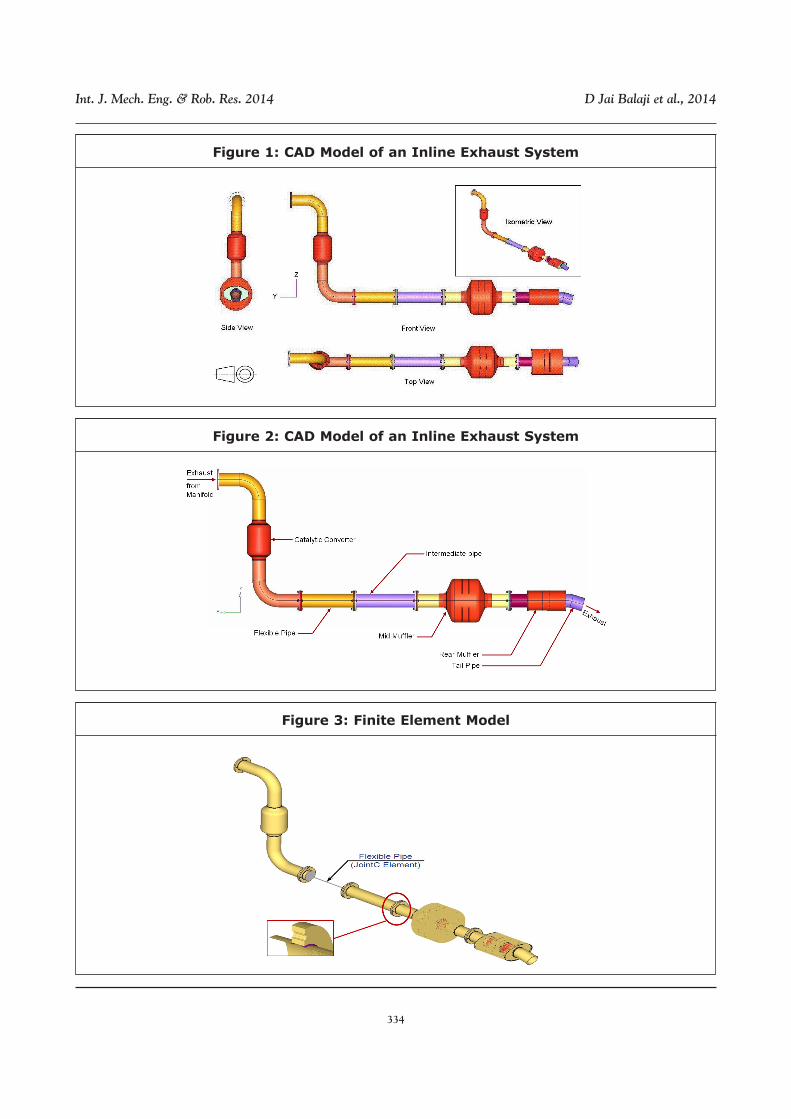
An exhaust system usually consists of pipes,acoustic and emission control componentsand decoupling elements. Since we areinterested in only Structural analysis of theexhaust system, the internal peripherals ofthe muffler and the catalytic convertor areneglected. An inline exhaust system isconsidered for analysis in this paper whichhas a catalytic converter at the inlet pipe, aflexible coupling, a resonator, a mid mufflerand rear muffler the exit. Figure 1 shows theCAD Model of an inline exhaust system andFigure 2 describe the parts of the same.
Finite Element Modeling ofExhaust System
The exhaust system cold end componentssuch as down pipe, catalytic converter,flexible coupling, under resonator, muffler and
tail pipe are made of stainless steel of variousgrades such as SS4501, SS308, SS4301 andFE410. CAD model was checked forgeometry cleanup and mid surface extraction.FE model was developed by using pre-processing software Hypermesh. The Figure3 shows the FE model of the exhaust system.Majority of components were modelled withshell elements (CQuad4) and flanges weremodelled with solid elements (CHexa). Theconnections between flange and bracket boltholes were made with rigid elements i.e.RBE2. The welded seams were modelledusing solid elements (CHexa & CPenta).When modeling welded seams, it is importantto ensure that at least one row of shell is lyingentirely on the solids in order to depict theconnection with sufficient resistance tobending. C3D6 elements form the runout ofthe fillet welds. The flexible coupling wasrepresented using a Joint C spring element.To define tie contacts between surfaces,contact manager was used in Hypermesh.
Perforated or punched metal pipes werealso taken into account in the modellingprocess. This was done by inserting aseparate shell component. Depending on thetype of perforation, the wall thickness is tobe revised lesser than the unpunchedcondition. The value was taken as around 80- 85% of the initial value. The Table 1 showsthe different materials used for different partswith their properties.
Table 1: Material Properties
Sl.
No.
1
2
Parts
Pipes & Flanges
Weld
Material Name
SS4510
SS308
Young’s modulus,
N/mm2
2.16 E+05
1.90 E+05
Poisson’s
ratio
0.30
0.28
Density,
T/mm3
7.6 E-09
7.9 E-09
334
Int. J. Mech. Eng. & Rob. Res. 2014 D Jai Balaji et al., 2014
Figure 1: CAD Model of an Inline Exhaust System
Figure 2: CAD Model of an Inline Exhaust System
Figure 3: Finite Element Model

335
Int. J. Mech. Eng. & Rob. Res. 2014 D Jai Balaji et al., 2014
MODEL ANALYSIS
Modal analysis is the study of properties ofstructures under vibrational excitation. Modalanalysis uses the overall mass and stiffnessof a structure to find the various periods atwhich it will naturally resonate during freevibration. Most of the times the only desiredmodes are the lowest frequencies becausethey can be the major modes at which thestructure will vibrate, dominating all the highermodes. The objective of free-free analysis isto make sure first 6 natural frequencies equalto zero. It is also a model check for FEM.
In free-free modal analysis no constraintsare applied to the system. Results includenatural frequency, mode shapes anddisplacement for each mode. Strain energyresults are in various forms and are used toidentify critical locations in the model for eachmode. If a location appears critical for severalmodes, then it definitely is a potential failurelocation.
RESULTS AND DISCUSSION
Table 2 shows the modes extracted from thefree-free modal analysis performed on theexhaust system. Block Lanczos method wasused to extract the mode shapes of the
Mode Number Frequency
1 9.23378E-05
2 3.23654E-04
3 4.09668E-04
4 5.77535E-04
5 5.85284E-04
6 6.23209E-04
7 2.0244
8 2.7619
9 3.2646
10 4.7640
11 21.861
12 24.119
13 101.40
14 106.89
15 110.15
16 113.49
17 216.69
18 225.27
19 285.54
20 306.27
Figure 3: Showing 9th Mode of Exhaust System with Bending in Z-Direction
Table 2: Modes and Frequencies

336
Int. J. Mech. Eng. & Rob. Res. 2014 D Jai Balaji et al., 2014
exhaust system. The first six modes showsrigid body modes in three linear directionsand rotational directions which are zero orequal to zero. This is one of the finite elementvalidation methods for free–free modalanalysis.
The nodal points shown in the Figure 3and Figure 4 are at mode 9 and mode 14due to bending in Z-direction where thedisplacement is zero.
CONCLUSION
This paper deals with the study of an exhaustsystem in general, using modal analysis. Themode shapes observed from Finite ElementAnalysis is mostly in transverse directions.
So the excitation points are chosen suchthat it excites the system in both thetransverse directions. It will give the generalguidelines on how to perform modal analysisin the initial stage of the project and checkfor nodal and anti-nodal points from modeshape animation. The nodal points are to beconsidered as preliminary hanger locationsfor the exhaust system as this is where thedisplacement is minimum.
Figure 4: Showing 14th Mode of Exhaust System with Bending in Z-Direction
SCOPE OF FUTURE WORK
Further to the above analysis static anddynamic analysis, temperature distributionanalysis, thermal stress analyses can beperformed in order to simulate componentssuch as catalytic converter, manifold flange,front pipes, flexible coupling etc.
ACKNOWLEDGMENT
The authors would like to thank everyone whowas helpful in providing necessaryinformation and for their support.
REFERENCES
1. Arun Viswanathan and Dr Elaya Perumal(2009), “Deciding Isolator and MountingPoints of a Truck’s Exhaust SystemBased on Numerical and ExperimentalModal Analysis”, ICSV 16, Krakow.
2. Marcus Myrén and Jörgen Olsson(1999), “Modal Analysis of ExhaustSystem”, M S Thesis, University ofKarlskrona/Ronneby.
3. P Verboven, R Valgaeren, M VanOvermeire and P Guillaume (1998)“Some Comments on Modal Analysis

337
Int. J. Mech. Eng. & Rob. Res. 2014 D Jai Balaji et al., 2014
Applied to Automotive Exhaust System”,16th International Modal AnalysisConference, IMAC XVI.
4. Thomas Englund, “DynamicCharacteristics of Automobile ExhaustSystem components”, M S Thesis,University of Karlskrona/Ronneby, 2003.


![Presented By - Aryan CollegeBALAJI BALAJ1i BALAJI NAMKEE,v BALAJI NAM KEEN Kna BAL BALAJI sNAFERS BALAJii BALAJI AN AFERS BALAJI 0ÈERs BALAJI BALAJI only BALAJI Ctlinese ej/ffJ1]JžfJ](https://img.dokumen.tips/doc/110x75/5eaecb507cb6087a2d0ae9dc/presented-by-aryan-college-balaji-balaj1i-balaji-namkeev-balaji-nam-keen-kna.jpg)