Embed Size (px)
Citation preview
Service Manual
Model E1070 Indicator
E1070
ENGLISH
43099-0010A e1 May 30, 2006
*43099-0010*

2 Model E1070 Indicator Service Manual
CAUTION: DANGER OF EXPLOSION IF BATTERY IS INCORRECTLYREPLACED. REPLACE ONLY WITH THE SAME OR EQUIVALENT TYPE RECOMMENDED BY
THE MANUFACTURER. DISPOSE OF USED BATTERIES ACCORDING TO THEMANUFACTURER'S INSTRUCTIONS.
ATTENTION: IL Y A DANGER D'EXPLOSION S'IL Y A REMPLACEMENT INCORRECT DE LA BATTERIE,REMPLACER UNIQUEMENT AVEC UNE BATTERIE DU MÊME TYPE OU D'UN TYPE ÉQUIVALENT
RECOMMANDÉ PAR LE CONSTRUCTEUR. METTRE AU REBUT LES BATTERIES USAGÉESCONFORMÉMENT AUX INSTRUCTIONS DU FABRICANT.
CAUTION: THE POWER SUPPLY CORD IS USED AS THE MAIN DISCONNECT DEVICE, ENSURE THAT THESOCKET-OUTLET IS LOCATED/INSTALLED NEAR THE EQUIPMENT AND IS EASILY ACCESSIBLE
ATTENTION: LE CORDON D'ALIMENTATION EST UTILISÉ COMME INTERRUPTEUR GÉNÉRAL. LA PRISEDE COURANT DOIT ÊTRE SITUÉE OU INSTALLÉE À PROXIMITÉ DE
L'ÉQUIPEMENT ET ÊTRE FACILE D'ACCÉS".
E1070_rev2006_s.P65

3Model E1070 Indicator Service Manual
Table of ContentsIntroduction .......................................................................................................................5Front Panel ........................................................................................................................5
Keys .........................................................................................................................6Annunciators ...............................................................................................................7
Error Messages .................................................................................................................8Accessing the Menus ..................................................................................................9User Menu ................................................................................................................ 10
Service Menu ..................................................................................................................12CAL submenu for analog scales .........................................................................12SCALE submenu .................................................................................................16APP submenu .....................................................................................................27
Master Reset .................................................................................................27Extra Info: Print Format Editing ................................................................................32
Thermal Labels Print Formats .............................................................................34SERIAL submenu ................................................................................................38TEST submenu ................................................................................................... 49AUDIT submenu .................................................................................................. 54INPUT submenu .................................................................................................. 55OUTPUT submenu ..............................................................................................57OPTION submenu ............................................................................................... 58
Supervisor Menu .......................................................................................................86DATE (Set date) ............................................................................................ 87HOUR (Set time) ........................................................................................... 87SETUP (Setup menu).................................................................................... 88TEST ...........................................................................................................101(Test menu) .................................................................................................101AUDIT (Audit counters) menu .....................................................................105
SensorComm Hardware Configuration and Calibration ...............................................106Enable SensorComm ........................................................................................106
Enable/Configure Weigh-Bars ................................................................................107CAL submenu for SensorComm scales .................................................................108
CORNER (SensorComm Cornering) ..........................................................108GHOST (Ghost Calibration Factors) ...........................................................109
SensorComm Error Messages......................................................................................110Appendix A: Remote Display Functionality ...................................................................111Appendix B: Mainboard Network LED Diagnostics .......................................................115Appendix C: Network Connections ...............................................................................116Appendix D: Complete Menu Structures.......................................................................118Technical Illustrations ...................................................................................................121

4 Model E1070 Indicator Service Manual
ODVA™, Ethernet/IP™ and DeviceNet™ are trademarks of ODVA.PROFIBUS® is a registered trademark of PROFIBUS International.
SpecificationsPower requirements
• 85-265 Volts AC @ 0.3Amp maximum• 50/60 Hz
Excitation• +/- 5 volts DC• Supports up to eight 350-ohm weight sensors
Analog signal input range• +/-60 mV
Analog signal sensitivity• 0.2 µV/V/divisions minimum• 1.0 µV/V/divisions recommended
Calibration2 to 5 points stored
Operational keys• Twenty-two keys: Tare, Select, Zero, Print, Units,
F1, Clear, Mode, Escape, Enter, On/Off, Decimal,0-9 numeric
Operational annunciators• Center of Zero, Motion, Gross, Net, Tare,• Under/Target//Over• Units of measure (LB, KG)• Print, OP1, OP2, OP3, Pt Tare
Display• Six-digit, seven-segment, 0.8-inch high, LED
Display rate• Selectable (1, 2, 5, 10)
Analog to digital conversion rate• 100 times per second
Unit of measure• Pounds, kilograms, custom
Capacity selections• 999,999 with decimal located from zero to five
placesIncremental selections
• Multiples and sub-multiples of 1, 2, 5Configurable selections
• Zero range, motion detection, automatic zerotracking, five-point linearization.
Time and date/RAM• Battery backed up real time clock and RAM
standardInternal resolution
• 53,687,100 counts per mV/V per secondHarmonizer™ digital filtering
• Fully configurable to ignore noise and vibration
Standard inputs• Three logic level inputs for: Zero, Print, Tare,
Units, F1, Start and StopStandard outputs
• 10/100 Ethernet (Modbus/TCP, TCP/IP, SMTP,DHCP, Ethernet/IP)
• PROFIBUS DP• DeviceNet• Three cutoff outputs• Two serial ports
• RS-232/422/485 (SensorComm) selectable• RS-232 or 20mA current loop
Serial Command Inputs/Outputs• Configurable serial response to ASCII character
input• SMA protocol, Broadcast, Enquire, RD-4100, E-
series remote displaySelf diagnostics
• Display, keys, inputs, outputs, serial port, A to Dconverter
Circuitry protection• RFI, EMI, and ESD protection
Options• Analog output/Pulse input• ControlNetTM
• TIU3• Remote I/O• Washdown remote foot control
Operating applications• General weighing, Accumulation, Batching,
Counting, Checkweighing, Peak measurement,Remote display
Operating temperature• 14 to 104° F (-10 to 40° C) approved• -40 to 140° F (-40 to 60° C) non-legal• Up to 95% non-condensing humidity
Enclosure• Stainless steel NEMA 6/4X
Dimensions• 9.25" W x 9.25" H x 4.5" D (without mountingbracket)• 9.75" W x 11" H x 7" D (with mounting bracket)
Weight• 8.5 lb, 4 kg
Agencies• NTEP CC#04-031 Class III/IIIL:10,000 divisions• OIML Cert. #R/76/1992-GB1-E410• Canadian Weights and Measures pending• UL/CUL• CE marked

5Model E1070 Indicator Service Manual
IntroductionAbout This Manual This manual covers the information you need to configure and service your
Model E1070 Indicator.
Major sections of this manual are headed by titles in a black bar like Intro-duction above. Subheadings appear in the left column. Instructions and textappear on the right side of the page. Occasionally notes, tips, and specialinstructions appear in the left column.
Front PanelThe front panel, shown in Figure 1, consists of the keys and display.
Figure 1E1070 front panel
Plug the Model E1070 intoproperly grounded socket-outlet of the correct voltage,installed near the equipmentand easily accessible. Neveruse the unit without an appro-priate earthground connection.
Any computer based systemshould have a separate,grounded power circuit. Werecommend one for theModel E1070.
See the System Block Diagramor Main Board Assembly pagesin the technical illustrations atthe back of this manual forwiring instructions.
6 Model E1070 Indicator Service Manual
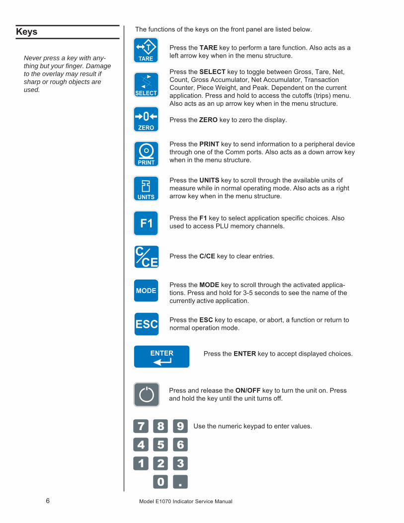
Keys The functions of the keys on the front panel are listed below.
Never press a key with any-thing but your finger. Damageto the overlay may result ifsharp or rough objects areused.
Press the TARE key to perform a tare function. Also acts as aleft arrow key when in the menu structure.
Press the SELECT key to toggle between Gross, Tare, Net,Count, Gross Accumulator, Net Accumulator, TransactionCounter, Piece Weight, and Peak. Dependent on the currentapplication. Press and hold to access the cutoffs (trips) menu.Also acts as an up arrow key when in the menu structure.
Press the ZERO key to zero the display.
Press the PRINT key to send information to a peripheral devicethrough one of the Comm ports. Also acts as a down arrow keywhen in the menu structure.
Press the UNITS key to scroll through the available units ofmeasure while in normal operating mode. Also acts as a rightarrow key when in the menu structure.
Press the F1 key to select application specific choices. Alsoused to access PLU memory channels.
Use the numeric keypad to enter values.
Press the C/CE key to clear entries.
Press the MODE key to scroll through the activated applica-tions. Press and hold for 3-5 seconds to see the name of thecurrently active application.
Press the ESC key to escape, or abort, a function or return tonormal operation mode.
Press the ENTER key to accept displayed choices.
Press and release the ON/OFF key to turn the unit on. Pressand hold the key until the unit turns off.

7Model E1070 Indicator Service Manual
Annunciators There are several annunciators around the edge of the display. The illustra-tion below explains each one.
Preset Tare
Network orSensorComm
status
Accumulator,Count
Output 3Output 2
Output 1
Tare weight
Net weight
Center of zero
MotionGross weight
Checkweighinggraph
Pound
Kilogram
Custom Unit
Center of Zero Lights when weight on the scale is within the zero range
Motion Lights during scale motion.
Gross Lights when gross weight is displayed
Net Lights when net weight is displayed
Tare Lights when tare weight is displayed
Print Lights when print format sent through serial port
OP 1 Lights when output one is activated
OP 2 Lights when output two is activated
OP 3 Lights when output three is activated
PT Lights when preset tare is active
Network & This is a configurable light to show status of the NetSensorComm work 1, Network 2 or SensorComm. See note at left.Status
Accumulator, Lights when an accumulation occurs and while in theCount count and peak applications
Custom Unit Lights when a custom unit of measure is active
KG Lights when kilograms is the active unit of measure
LB Lights when pounds is the active unit of measure
Checkweigher Lights when checkweighing application is active
Bottom LED color whenconfigured for:
SCOM (SensorComm):Red – a cell has been ghosted.Check the ghost log.Green – a sensorcomm errorhas occurred. Print the errorlog.Off – Scale is functioningnormally.
Network 1 or 2:Red – A network error hasoccurred. Check the networksettings on the indicator andPLC, and reboot the indicator.Green – The network connec-tion has been established.Amber – The network is readyfor a connection, but noconnection has been estab-lished.
8 Model E1070 Indicator Service Manual
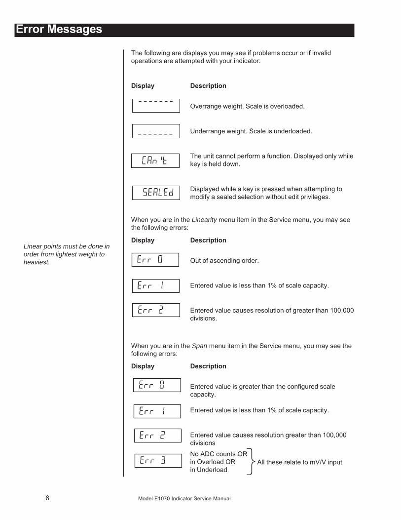
Error Messages
The following are displays you may see if problems occur or if invalidoperations are attempted with your indicator:
Display Description
Overrange weight. Scale is overloaded.
Underrange weight. Scale is underloaded.
The unit cannot perform a function. Displayed only whilekey is held down.
Displayed while a key is pressed when attempting tomodify a sealed selection without edit privileges.
When you are in the Linearity menu item in the Service menu, you may seethe following errors:
Display Description
Out of ascending order.
Entered value is less than 1% of scale capacity.
Entered value causes resolution of greater than 100,000divisions.
When you are in the Span menu item in the Service menu, you may see thefollowing errors:
Display Description
Entered value is greater than the configured scalecapacity.
Entered value is less than 1% of scale capacity.
Entered value causes resolution greater than 100,000divisions
All these relate to mV/V inputNo ADC counts ORin Overload ORin Underload
Linear points must be done inorder from lightest weight toheaviest.

9Model E1070 Indicator Service Manual
Menu StructureThere are several menus you use to setup or service the Model E1070. Youaccess the menus through the front panel. Each menu is briefly describedhere. For in depth information about a menu, go to that menu's section inthis manual.
User menu (password is 111)The first menu covered in this manual is the User menu. Thismenu allows the user to:
• view software part numbers and revision level• view mV/V output of the scale• test the display and buttons• test the serial ports• audit the number of configurations and calibrations per-
formed on the indicator
Service menu (password is 0701)The second menu covered is the Service menu. In it you can:
• calibrate the scale system• configure the metrological functions of the indicator• enable or disable available applications• configure serial ports• test the display and buttons, test the serial ports, test the
inputs and outputs• audit the number of configurations and calibrations per-
formed on the indicator• configure inputs and outputs and options
Supervisor menu (password is 1793)The third menu is the Supervisor menu. This section lets you:
• set time and date• clear and/or print data gathered by each application• choose special modes of operation for applications• test the display and buttons, test the serial ports, test the
inputs and outputs, analog output, pulse counter input andnetworks
• audit the number of configurations and calibrations per-formed on the indicator
• configure recipes, ingredients, sample mode, over/undervalues
1. Access the menus by pressing and holding the ESC key for 3-5 sec-onds. See note on upper left of this page.
PASS_ is displayed.
2. Key in the password of the menu you want to enter and press ENTER.The first item in that menu is displayed.
3. Use the navigation keys shown in the box near each menu to movethrough the menu.
Accessing the Menus
You must begin to key in thepassword within 10 seconds orthe display returns to normaloperation mode.
The indicator must be unsealedto change anything in theService menu. Placing ajumper on P3 in the enclosureunseals the indicator. Seephotos below.
Sealed
Unsealed

10 Model E1070 Indicator Service Manual
User Menu The User menu lets you test various functions of the indicator. The Usermenu is shown in Figure 2.
Figure 2User menu flowchart
Following are specific instructions for the User menu.
1. Access the User menu by pressing and holding the ESC key for 3-5seconds.
PASS_ is displayed.
2. Key in the User menu password (111) and press ENTER.TEST is displayed.
3. Press the PRINT key.ABOUT is displayed. Press the PRINT key then the UNITS keyrepeatedly to view the part number and revision level for thesoftware found in your indicator.
Press SELECT key to return to ABOUT.
4. Press the UNITS key…ADC is displayed. This stands for the analog to digital convertervalue in mV/Vs.
5. Press the PRINT key…The mV/V value coming into the indicator is displayed. This shouldchange as weight on the scale changes. Press the ZERO key tozero the mV/V reading prior to diagnostics.
6. Press the SELECT…ADC is displayed.
7. Press the UNITS key…DISP is displayed. This is the display test item.
While in a menu, the fangraphs at the top of the displayflash as a reminder.

11Model E1070 Indicator Service Manual
8. Press the PRINT key to perform a dynamic test of the display…Display lights all digits and annunciators and continues to flash.
9. Press ESC key to stop the dynamic test.10. Press the UNITS key…
BUTTON is displayed. This is the button test item.
11. Press the PRINT key to perform a button test. Each key you press willbe reflected on the display screen to confirm the button is functioningcorrectly. The ESC key is excluded from this test. It is used to stop thetesting and return to the menu item
12. Press ESC key to stop the button test.BUTTON is displayed.
13. Press the UNITS key…SERIAL is displayed. This is the serial test item.
14. Press the PRINT key to access the serial test.PORT1 is displayed. If you jumper the transmit and receive lineson the serial port, as shown at left, and press the PRINT key, thedisplay should show PASS. If there is a problem the display willshow FAIL.
Repeat this for PORT 2.
15. Press the SELECT key to exit the serial test.SERIAL is displayed.
16. Press the SELECT key…TEST is displayed.
17. Press the UNITS key…AUDIT is displayed.
18. Press the PRINT key…CFG is displayed. This stands for the configuration audit counter.
19. Press the PRINT key to see the number of times the configuration hasbeen altered on this indicator.
20. Press the SELECT or ENTER key…CFG is displayed.
21. Press the UNITS key…CAL is displayed. This stands for the calibration audit counter.
22. Press the PRINT key…The number of times the indicator has been calibrated is dis-played.
23. Press ESC twice to return to normal operation mode.
This completes the User menu.
Calibration and configurationcounters cannot be reset.
User Menu—(continued)

12 Model E1070 Indicator Service Manual
Service Menu The first level of the Service menu is shown in Figure 3. Under these itemsyou can do most of the configuration and calibration procedures to ready theindicator for use. Other items are covered in the Supervisor menu sectionlater in this manual.
Figure 3Service menu top level flowchart
Since the whole Service menu is quite large, it has been broken up into itsindividual submenus. Each submenu is illustrated in this section followed byspecific instructions for that submenu.
If your system is using analog scales, use the menu shown in Figure 4. Ifyour system is configured for SensorComm under the Service Menu>Scale>Source menu item, follow the CAL menu, Figure 15, in the section titled CALsubmenu for SensorComm scale later in this manual.
Figure 4CAL submenu for analog scales
1. Access the Service menu…CAL is displayed.
2. Press the PRINT key…ZERO is displayed. Use this item to set the zero reference for theindicator/scale.
Password for the Service menuis 0701.
While in a menu, the fangraphs at the top of the displayflash as a reminder.
CAL submenu foranalog scales
ZERO(Setting Zero Reference Point)
Press the ESC key to abortcalibration.

13Model E1070 Indicator Service Manual
3. Remove all weight from the scale and press the ENTER key…Live weight is shown.
4. Press the ENTER key to perform the zero procedure…BUSY is briefly displayed then the live weight which should be 0.
5. Press the ENTER key to save and return to the ZERO menu item…ZERO is displayed.
1. Press the UNITS key…SPAN is displayed. Use this item to set the span for the indicator/scale.
2. Press the PRINT key…Current capacity is displayed.
3. Key in a new span weight value and press ENTERorpress ENTER to accept current span weight value…
The live weight is displayed.
4. Place the correct span weight on the scale and press ENTER whenweight is stable.
BUSY is briefly displayed then the weight.
5. Press the ENTER key to accept the calibration and return to the SPANmenu item…
SPAN is displayed.
6. Press ESC to exit to normal weighing mode (You will be prompted tosave the changes. Press ENTER to save changes)OR go to step 1 below.
1. Press the UNITS key…LINEAR is displayed. Use this item to set extra calibration points.
2. Press the PRINT key…2 is displayed. This represents cal point 2.
3. Press the ENTER key to set this calibration point…A numeric value is displayed.
4. Key in a weight value for this calibration point and press the ENTER key.Live weight on the scale is displayed.
5. Place the test weight for this calibration on the scale and press ENTER.Busy is briefly displayed and then 2.
LINEAR(Linearization)
SPAN(Setting Span)
Press the ESC key to abortcalibration.
Linear points must be done inorder from lightest weight toheaviest.
Service Menu—Analog CAL submenu (continued)

14 Model E1070 Indicator Service Manual
6. Press the UNITS key to move to the next calibration point…3 is displayed.
7. Repeat steps 3-6 for cal point 3 and 4.When you are done 4 will be displayed.
8a. Press the SELECT key to return to the LINEAR menu item.OR
8b. Press the ESC key to return to normal operating mode. You will beprompted to save the changes. Press ENTER to save them or the ESCkey to abort the save process and return to normal operating modewithout saving calibration.
Use this item to hand enter zero and span calibration factors. This is usefulif one indicator fails and is replaced with another but no test weights areavailable. Linearization factors cannot be entered.
1. Press the UNITS key…INPUT is displayed.
2. Press the PRINT key…ZERO is displayed.
3. Press the PRINT key…A numeric value is displayed.
4. Key in the zero factor from your previous indicator and press the ENTERkey.
BUSY is briefly displayed, then ZERO.
5. Press the UNITS key…SPAN is displayed.
6. Press the PRINT key…A numeric value is displayed.
7. Key in the span factor from your previous indicator and press theENTER key…
A span weight is displayed.
8. Accept the span weight by pressing the ENTER key or key in a newspan weight and press the ENTER key to accept it…
BUSY is briefly displayed, then SPAN.
9. Press the SELECT key to return to the INPUT menu item.
INPUT(Input Calibration)
To use this item you must haverecorded the calibration factorsfrom your previously installedE1070 indicator.
Calibration factors can beviewed under CAL>INPUT oryou can print them out usingthe CAL>PRINT menu item.
Service Menu—Analog CAL submenu (continued)

15Model E1070 Indicator Service Manual
DISP(Live Weight Display)
1. Press the UNITS key…DISP is displayed. Use this item to view the live weight on thescale without exiting the Service menu.
2. Press the PRINT key…The live weight is displayed.
3a. Press the SELECT key…DISP. is displayed.
OR3b. Press the SELECT key to move to the top of the Service menu…
CAL is displayed.
1. Press the UNITS key…PRINT is displayed. This item lets you print a calibration report.The information printed can be very useful in case of serviceissues later.
2. Press the PRINT key…PORT 1 is displayed. The other choice is PORT 2. This allows youto choose a port through which the calibration report is printed.
3. Toggle between the choices using the TARE or UNITS key and pressENTER when your choice is displayed…
The report is printed and the display returns to PRINT.
4a. Press the SELECT key to return to the CAL item of the Service menuand continue with the Service menu instructions in the next sectionOR
4b. Press the ESC key to return to normal operation mode.SAVE is displayed.
5. Press the ENTER key to save changes or press the ESC key to exit themenu without saving.
This completes the CAL section of the Service menu for analog scales. Ifyou have a SensorComm system, see the section SensorComm HardwareConfiguration and Calibration for calibration and configuration information.
The next Service menu item, SCALE, is covered in the SCALE Submenusection.
PRINT(Print a Calibration Report)
Service Menu—Analog CAL submenu (continued)

16 Model E1070 Indicator Service Manual
SCALE submenu Use this section of the Service menu for scale configuration. Figure 5 showsthe flowchart of this menu item. Follow the directions and explanationsbelow to set up these items.
Figure 5Scale submenu flowchart
Source(Analog or SensorComm)
1. Access the Service menu…CAL is displayed.
2. Press the UNITS key…SCALE is displayed.
3. Press the PRINT key…SOURCE is displayed. Use this item to choose between ananalog or SensorComm based system.
4. Press the PRINT key…The current setting is displayed.
5. Toggle between the Analog and Scom (North America only) choicesusing the TARE or UNITS key. When your choice is displayed press theENTER key…
SOURCE is displayed.
Calibration instructions forAnalog scales are in thesection—CAL submenu foranalog scales
Calibration instructions forSensorComm scales are in thesection—CAL submenu forSensorComm scales

17Model E1070 Indicator Service Manual
CAP.(Capacity)
1. Press the UNITS key…CAP. is displayed. Use this item to set the capacity for the scale.
2. Press the PRINT key…The current capacity value is shown.
3. Press ENTER to accept this value or key in a new capacity and pressENTER…
CAP. is displayed.
This item and the next one, DP.POS., set the division size.
1. Press the UNITS key…DIV. is displayed. This stands for the division value of yourdisplayed weight.
2. Press the PRINT key…The current division value is shown.
3. Scroll through the choices by using the TARE or UNITS key.Pick from the following values; 1, 2, 5, 10, 20, 50, 100, 200, 500,1/2, 2/5, 5/10, 10/20, 20/50.
The fraction choices are for use as dual range divisions. Thefirst number is the division value for the first half of thecapacity and the second number is the division value for the2nd half of the capacity.
All of these capacities function in conjunction with the decimalplace position. For example, if you choose a division value of 5and a decimal position of 12345.6, your division size will be .5.
4. When your choice is displayed, press ENTER.DIV. is displayed.
Use this item to set the decimal point position in the displayed weight.
1. Press the UNITS key…DP.POS. is displayed. This stands for decimal point position.
2. Press the PRINT key…The current decimal point position is shown. Choices availableare; 123456, 12345.6, 1234.56, 123.456, 12.3456 and 1.23456.
3. Scroll through the choices by using the TARE or UNITS key. When yourchoice is displayed, press ENTER.
DP.POS. is displayed.
DIV.(Division)
Service Menu—SCALE submenu (continued)
DP.POS.(Decimal point position)

18 Model E1070 Indicator Service Manual
UNITS(Unit of measure)
You can have up to three units of measure active. They are lbs, kgs, or acustom unit of measure.
Follow these steps:
1. Press the UNITS key…UNITS is displayed.
2. Press the PRINT key…LB is displayed.
3. Turn each unit of measure ON or OFF by scrolling to the unit by usingthe TARE or UNITS key and pressing the PRINT key…
The current state of the unit is displayed.
4. For lbs and kgs, toggle between ON or OFF by using the TARE orUNITS key. Press ENTER when your choice is displayed…
Display returns to LBS or 1000G.
If you choose to activate the custom unit of measure you will beprompted for a multiplier which defines the custom unit in relation to thecalibration unit of measure and a string entry for a unit label. See note atleft. Key the multiplier in and press ENTER to enter the value.
String entry screen is displayed. Edit the string (up to sevencharacters long) to create a name for the custom unit of measure.For directions on string editing, see the section Extra Info: PrintFormat Editing. String editing is covered in that section.
5. Press ENTER key to accept the string values …CUST. is displayed.
6. Press the UNITS key…C-UNIT is displayed. This stands for calibration unit. Use this itemto set the calibration unit of measure; lbs or kgs (1000 G).
7. Press the PRINT key…Current calibration unit is displayed. Choices are lb or 1000G.
8. Toggle between the choices by using the TARE or UNITS key and pressthe ENTER key to accept the choice…
C-UNIT is displayed.
9. Press the SELECT key…UNITS is displayed.
Service Menu—SCALE submenu (continued)
If your new custom unit islarger than one CAL UNIT,then you key in how many CALUNITS make up 1 new customunit. For example 1 TON =2000 pounds so with poundsselected as our CAL UNIT wewould key in 2000 for themultiplier.
one cal unitnumber of custom units
If your new custom unit issmaller than one CAL UNIT,then you divide one cal unit bythe number of custom units ittakes to make up a single CALUNIT. Multipliers are limited toa total of seven digits by thedisplay.
Example #1:16 ounces = 1 pound.Do the math:(one cal unit / number ofcustom units = the multiplier)1/16=0.0625So with pounds selected as ourCAL UNIT we would key in0.0625 for the multiplier.
Example #2:1000 Grams = 1 KG.Do the math: (one cal unit / number ofcustom units = the multiplier)1/1000=0.001So with KG selected as ourCAL UNIT we would key in0.001 for the multiplier.
19Model E1070 Indicator Service Manual
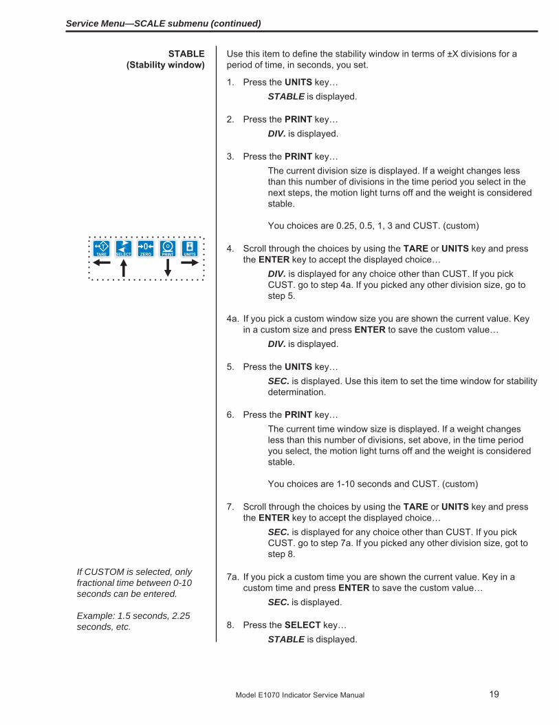
STABLE(Stability window)
Use this item to define the stability window in terms of ±X divisions for aperiod of time, in seconds, you set.
1. Press the UNITS key…STABLE is displayed.
2. Press the PRINT key…DIV. is displayed.
3. Press the PRINT key…The current division size is displayed. If a weight changes lessthan this number of divisions in the time period you select in thenext steps, the motion light turns off and the weight is consideredstable.
You choices are 0.25, 0.5, 1, 3 and CUST. (custom)
4. Scroll through the choices by using the TARE or UNITS key and pressthe ENTER key to accept the displayed choice…
DIV. is displayed for any choice other than CUST. If you pickCUST. go to step 4a. If you picked any other division size, go tostep 5.
4a. If you pick a custom window size you are shown the current value. Keyin a custom size and press ENTER to save the custom value…
DIV. is displayed.
5. Press the UNITS key…SEC. is displayed. Use this item to set the time window for stabilitydetermination.
6. Press the PRINT key…The current time window size is displayed. If a weight changesless than this number of divisions, set above, in the time periodyou select, the motion light turns off and the weight is consideredstable.
You choices are 1-10 seconds and CUST. (custom)
7. Scroll through the choices by using the TARE or UNITS key and pressthe ENTER key to accept the displayed choice…
SEC. is displayed for any choice other than CUST. If you pickCUST. go to step 7a. If you picked any other division size, got tostep 8.
7a. If you pick a custom time you are shown the current value. Key in acustom time and press ENTER to save the custom value…
SEC. is displayed.
8. Press the SELECT key…STABLE is displayed.
If CUSTOM is selected, onlyfractional time between 0-10seconds can be entered.
Example: 1.5 seconds, 2.25seconds, etc.
Service Menu—SCALE submenu (continued)

20 Model E1070 Indicator Service Manual
For the purpose of explainingall items in the menus, theseinstructions show an orderlyaccessing of each part of themenu. You do not have toaccess an item in this way.Use the navigation buttons toskip around to the item youwant to change or view.
AZT(Automatic Zero Tracking)
Use this item to set the division size and seconds. The division size you pickdefines a range above and below zero. When scale weight is inside thisrange for the number of seconds you picked, ½ of the weight will be zeroed.The indicator will repeat removing ½ the weight every X seconds. X beingthe number of seconds you have picked.
1. Press the UNITS key…AZT is displayed.
2. Press the PRINT key…DIV. is displayed.
3. Press the PRINT key…The current division size is displayed.
You choices are 0.25, 0.5, 1, 3 and CUST. (custom)
4. Scroll through the choices by using the TARE or UNITS key and pressthe ENTER key to accept the displayed choice…
DIV. is displayed for any choice other than CUST. If you pickCUST. go to step 4a. If you picked any other division size, got tostep 5.
4a. If you pick a custom window size you are shown the current value. Keyin a custom size and press ENTER to save the custom value…
DIV. is displayed.
5. Press the UNITS key…SEC. is displayed. Use this item to set the time window for stabilitydetermination.
6. Press the PRINT key…The current time window size is displayed.
You choices are 1-10 seconds and CUST. (custom)
7. Scroll through the choices by using the TARE or UNITS key and pressthe ENTER key to accept the displayed choice…
SEC. is displayed for any choice other than CUST. If you pickCUST. go to step 7a. If you picked any other division size, got tostep 8.
7a. If you pick a custom time you are shown the current value. Key in acustom time and press ENTER to save the custom value…
SEC. is displayed.
8. Press the SELECT key…AZT is displayed.
If CUSTOM is selected, onlyfractional time between 0-10seconds can be entered.
Example: 1.5 seconds, 2.25seconds, etc.
Service Menu—SCALE submenu (continued)

21Model E1070 Indicator Service Manual
TARE(Tare parameters)
Service Menu—SCALE submenu (continued)
Use this item to set the tare function parameters;
Clear tare If you enable (ON) this item, the tare will be automati-cally cleared when the weight falls below the value setunder the G-Band menu item.
Pushbutton tare If you enable this item (ON), you can use the TARE keyto tare a weight from the scale. If you disable (OFF) thisitem, you cannot tare using the TARE key.
Enter tare If you enable this item (ON), you can enter a known tareweight by keying in a weight and pressing the TAREkey.
Follow these steps to set the tare item:
1. Press the UNITS key…TARE is displayed.
2. Press the PRINT key…CLEAR is displayed.
3. Press the PRINT key…ON or OFF is displayed. Use this to enable or disable the Cleartare item.
4. Toggle between the choices by using the TARE or UNITS key and pressthe ENTER key to accept the displayed choice…
CLEAR is displayed.
5. Press the UNITS key…P.B. is displayed.
6. Press the PRINT key…ON or OFF is displayed. Use this to enable or disable the Push-button tare item.
7. Toggle between the choices by using the TARE or UNITS key and pressthe ENTER key to accept the displayed choice…
P.B. is displayed.
8. Press the UNITS key…ENTER is displayed.
9. Press the PRINT key…ON or OFF is displayed. Use this to enable or disable the Entertare item.
10. Toggle between the choices by using the TARE or UNITS key and pressthe ENTER key to accept the displayed choice…
ENTER is displayed.
11. Press the SELECT key…TARE is displayed.

22 Model E1070 Indicator Service Manual
AVG(Averaging of A-D)
Use this item to set the number of display updates/second. Choices are 1, 2,5 and 10 times/second. 10 is the default value.
1. Press the UNITS key…UPDATE is displayed.
2. Press the PRINT key…Current update rate is displayed. Choices are 1, 2, 5 and 10 timesper second.
3. Scroll through the choices by using the TARE or UNITS key and pressthe ENTER key to accept the displayed choice. .
UPDATE is displayed.
The AVG and FILTER menu items discussed below are best explained byan example of how the filtering works on this indicator.
Filtering is used to counteract vibration of the scale. The A-D weight conver-sion happens 100 times per second in the E1070. AVG is the number ofconversions you want to average. For example, if you pick 50, the unit willaverage the weight values from the last 50 conversions or ½ second anduses that value for displayed data.
If you turn the filtering on you need to set the Constant. Typical values arebetween 1-10. Set the number low for small vibration problems and higherfor more dampening effect.
The purpose of the Threshold is so the indicator will respond quickly to largeweight changes. Threshold is the amount of weight change, in calibrationunits, beyond which the filter will be temporarily disabled. For example, if youset this to 10 lbs, a weight change over 10 pounds occurring during thesample time (½ sec. in our example) will disable the filter until the weightchange during the sample time drops below 10 lbs.
AVG is the number of conversions you want to average for the weight that isdisplayed. 20 is the default value.
1. Press the UNITS key…AVG is displayed.
2. Press the PRINT key…The current value is displayed.
3. Press ENTER to accept the current valueORKey in a new value, between 0 and 512, and press ENTER to acceptit…
BUSY is briefly displayed, then AVG.
UPDATE(Display Update Rate)

23Model E1070 Indicator Service Manual
FILTER(Noise filtering)
Use this item to set the noise filtering parameters.
1. Press the UNITS key…FILTER is displayed.
2. Press the PRINT key…Current setting is displayed. Choices are OFF, FLTR 1 and FLTR2.
Off means no filtering. FLTR 1 filtering is slower response toweight in a longer time period with improved accuracy. FLTR 2filtering is faster response to weight in a short time.
3. Scroll through the choices by using the TARE or UNITS key and pressthe ENTER key to accept the displayed choice…
If you choose OFF, display returns to FILTER. You can continueto the next menu item (d.Point).
If you choose FLTR 1 or 2, continue to step 4.
4. With FLTR 1 or FLTR 2 displayed, press the PRINT key…CONST is displayed. This stands for Constant and is one of twofiltering parameters you need to set.
5. Press the PRINT key…Current value is displayed. For the Constant value you can pick avalue between 1 and 10. Set the number low for small vibrationproblems and use a higher setting for more dampening effect.
6. Scroll through the choices by using the TARE or UNITS key and pressthe ENTER key to accept the displayed choice…
CONST is displayed.
Service Menu—SCALE submenu (continued)

24 Model E1070 Indicator Service Manual
D.POINT(Decimal point)
7. Press the UNITS key…THRESH is displayed. This stands for Threshold, the 2nd filteringparameter.
Threshold causes the indicator to respond quickly to large weightchanges. Threshold is the amount of weight change, in calibrationunits, beyond which the filtering will be temporarily disabled. Forexample, if you set this to 10 lbs, a weight change over 10 poundsoccurring during the sample time will disable the filtering until theweight change during the sample time drops below 10 lbs.
8. Press the PRINT key…Current value is displayed.
9. Key in a value. Press the ENTER key…THRESH is displayed.
10. Press the SELECT key…FLTR 1 or FLTR 2 is displayed.
11. Press the SELECT key…BUSY is displayed briefly then FILTER. Whichever filter you setup becomes the active filter for the indicator.
Use this item to toggle between decimal point and a comma for the fractiondelimiter for the display. For example, if you pick DEC the display will show10.5. If you pick COMMA, the display will show 10,5.
1. Press the UNITS key…D.POINT is displayed.
2. Press the PRINT key…The current setting is displayed.
3. Toggle between the choices, DEC or COMMA, by using the TARE orUNITS key and press the ENTER key to accept the choice…
D.POINT is displayed.
A THRESHOLD setting of 0 willturn filtering on all the time.
Service Menu—SCALE submenu (continued)
Example:decimal = 000.00comma = 000,00

25Model E1070 Indicator Service Manual
0-RANGE(Zero range)
Use this item to key in a percentage of capacity, within which the ZERO keywill zero the scale.
1. Press the UNITS key…0-RNGE is displayed.
2. Press the PRINT key…The current setting is displayed. This is a percentage of capacity.
3. Key in a new value and press ENTER to accept the valueORPress the ENTER key to accept the displayed choice…
0-RNGE is displayed.
Use this item to set the point at which over range (upper) dashes aredisplayed. You can choose between 105% of capacity or 9 divisions overcapacity.
1. Press the UNITS key…O-CAP. is displayed.
2. Press the PRINT key…The current setting is displayed.
3. Toggle between the choices by using the TARE or UNITS key and pressthe ENTER key to accept the choice…
O-CAP. is displayed.
Use this item to set the gross zero band. This is a parameter used to triggerthe tare clear function covered previously in the Scale submenu.
You can enter values between 0 and 100 divisions.
1. Press the UNITS key…G-BAND is displayed.
2. Press the PRINT key…The current setting is displayed.
3. Key in a new value and press ENTER to accept the valueORPress the ENTER key to accept the displayed choice…
G-BAND is displayed.
O-CAP.(Over capacity range)
G-BAND(Gross zero band)
Service Menu—SCALE submenu (continued)

26 Model E1070 Indicator Service Manual
SERIAL(Serial number entry)
The serial number of yourindicator can be found on theaffixed tag on the outside of theindicator case.
C-ZERO(Center of zero window)
This item is to set the window size for the center-of-zero annunciator. Youcan choose between ±¼ and ±½ division. When the weight falls within thewindow size, the center-of-zero annunciator lights.
1. Press the UNITS key…C-ZERO is displayed.
2. Press the PRINT key…The current setting is displayed.
3. Toggle between the choices by using the TARE or UNITS key and pressthe ENTER key to accept the choice…
C-ZERO is displayed.
Use this item to enter the serial number for your indicator. This value is usedin some serial outputs and reports for record keeping purposes.
1. Press the UNITS key…SERIAL is displayed.
2. Press the PRINT key…The current setting is displayed.
3. Key in the serial number of your indicator and press ENTER to acceptthe valueORPress the ENTER key to accept the displayed choice…
SERIAL is displayed.
4. This completes the SCALE portion of the Service menu. You can exit tonormal weighing mode or continue on to the next menu item, APP. Toexit, go to step 5. To continue, go to step 7.
5. Press the ESC key.SAVE is displayed.
6. Press ENTER to save the changes you’ve madeORPress ESC to abort the changes…
Display returns to normal operation mode.
7. Press the SELECT key…SCALE is displayed.
8. Press the UNITS key…APP is displayed.
Service Menu—SCALE submenu (continued)

27Model E1070 Indicator Service Manual
APP submenu
Figure 6APP (applications) submenu
Follow these steps to access each item in the APP menu and to understandwhat they do and how to set them:
1. Access the Service menu…CAL is displayed.
2. Press the UNITS key twice…APP is displayed.
3. Press the PRINT key…SITE is displayed.
Use this item to choose your instrument location; NA (NorthAmerica), EU (Europe). Choosing the correct one will set defaultsto your location’s requirements.
4. Press the PRINT key…Current setting is displayed.
5. Toggle between the choices by using the TARE or UNITS key andpress the ENTER key to accept the displayed choice. .
SITE is displayed.
See note at left.
SITE(Setting site defaults)
The next section of the Service menu is the APP submenu. See Figure 6.This menu lets you choose the default parameters for your location and alsolets you enable or disable each application available in this indicator. Undereach enabled application you can edit the default print format (#0) andchoose which formats (#0-10) to print and through which port. You canconfigure the extra formats (#1-10) in the SERIAL submenu item in theService menu.
Applications are enabled in theService menu but you do eachapplication’s setup in theSupervisor menu.
Master ResetIf you change the site settingand save the change, thenchange it back to the originalsite and save, the defaults willbe reset to factory defaults.
This will not affect calibration,print formats or recipes.
In normal operating mode,press the MODE key tochange from one enabledapplication to the next.
* * Print format ‘0’ is used for this string. Strings#1-10 are located under the Serial submenu.

28 Model E1070 Indicator Service Manual
1. Press the UNITS key…ACC. is displayed. This stands for the Accumulator application.
2. Press the PRINT key…ON or OFF is displayed, depending on the current setting.
3. Press the SELECT key to back out of this item without enabling itORPress the ENTER key to enable this application…
STRING is displayed. This is where you can choose a port to printthrough and view and/or edit the default print format.
4. With STRING displayed, press the PRINT key…The current port setting appears. Choices are Port 1, Port 2,TCPIP1, TCPIP2, SMTP 1 or SMTP 2. See note at left.
5. Toggle between the choices by using the TARE or UNITS key and pressENTER to accept the displayed choice. .
A string of numbers appears. See note at left and example below.
These numbers represent the default print format in numberedsequence of hexadecimal commands. Each hexadecimal com-mand represents one printing character or print command. Thesenumbers allow you to customize the print output of the indicator.
See the Extra Info: Print Format Editing section for full explanationand instruction on modifying a print format.
6. Modify the print format as needed and press the ENTER key whenfinished. .
STRING is displayed.
7. Press the UNITS key…P-FT is displayed. This stands for print format. You can send oneor more print formats through a port each time the PRINT key ispressed. This is the item you use to define which formats getprinted.
8. Press the PRINT key…Numeric entry screen is displayed.
9. Key in the format numbers you want printed. See note at left. Forexample, to print formats 0, 1, and 4, key in 014 and press the ENTERkey. To print the 0, 1, 3, and 10 formats, key in 01310 and press theENTER key…
P-FT is displayed.
There are default printformats for each application.These are all given a formatnumber = 0.
ACC(Accumulator application)
When you key in a 1 followedby a 0, the indicator is smartenough to know this is a 10 notseparate 1 and 0 formats.
Always enter format numbersin ascending order.
If you choose TCPIP1 orSMTP1, Net 1 underOPTION>NETS must be set toE-net-1 or E-net-4.
If you choose TCPIP2 orSMTP2, Net 2 underOPTION>NETS must be set toE-net-1 or E-net-4.
Service Menu—APP submenu (continued)
You can exit the Service menuat any time by pressing theESC key. When SAVE appearson screen you can press ESCto lose any changes or pressENTER to save the changesand return to normal operatingmode.

29Model E1070 Indicator Service Manual
10. Press the SELECT key…ACC. is displayed.
11. Press the UNITS key…BATCH is displayed.
1. From previous step 11, press the PRINT key…Repeat steps 2-9 from the ACC (Accumulator application) sectionto set up the Batch application.
2. Press the SELECT key…BATCH is displayed.
3. Press the UNITS key…TARGET is displayed.
1. Press the PRINT key…Repeat steps 2-9 from the ACC (Accumulator application) sectionto set up the Target application.
2. Press the SELECT key…TARGET is displayed.
3. Press the UNITS key…COUNT is displayed.
1. Press the PRINT key…Repeat steps 2-9 from the ACC (Accumulator application) sectionto set up the Target application.
2. Press the SELECT key…COUNT is displayed.
3. Press the UNITS key…TOP is displayed.
1. Press the PRINT key…Repeat steps 2-9 from the ACC (Accumulator application) sectionto set up the Target application.
2. Press the SELECT key…TOP is displayed.
3. Press the UNITS key…R-DISP is displayed.
BATCH(Batch application)
TARGET(Checkweighing application)
COUNT(Counting application)
TOP(Peak hold application)
Service Menu—APP submenu (continued)
In normal operating mode,press the MODE key tochange from one enabledapplication to the next.
You can exit the Service menuat any time by pressing theESC key. When SAVE appearson screen you can press ESCto lose any changes or pressENTER to save the changesand return to normal operatingmode.
30 Model E1070 Indicator Service Manual
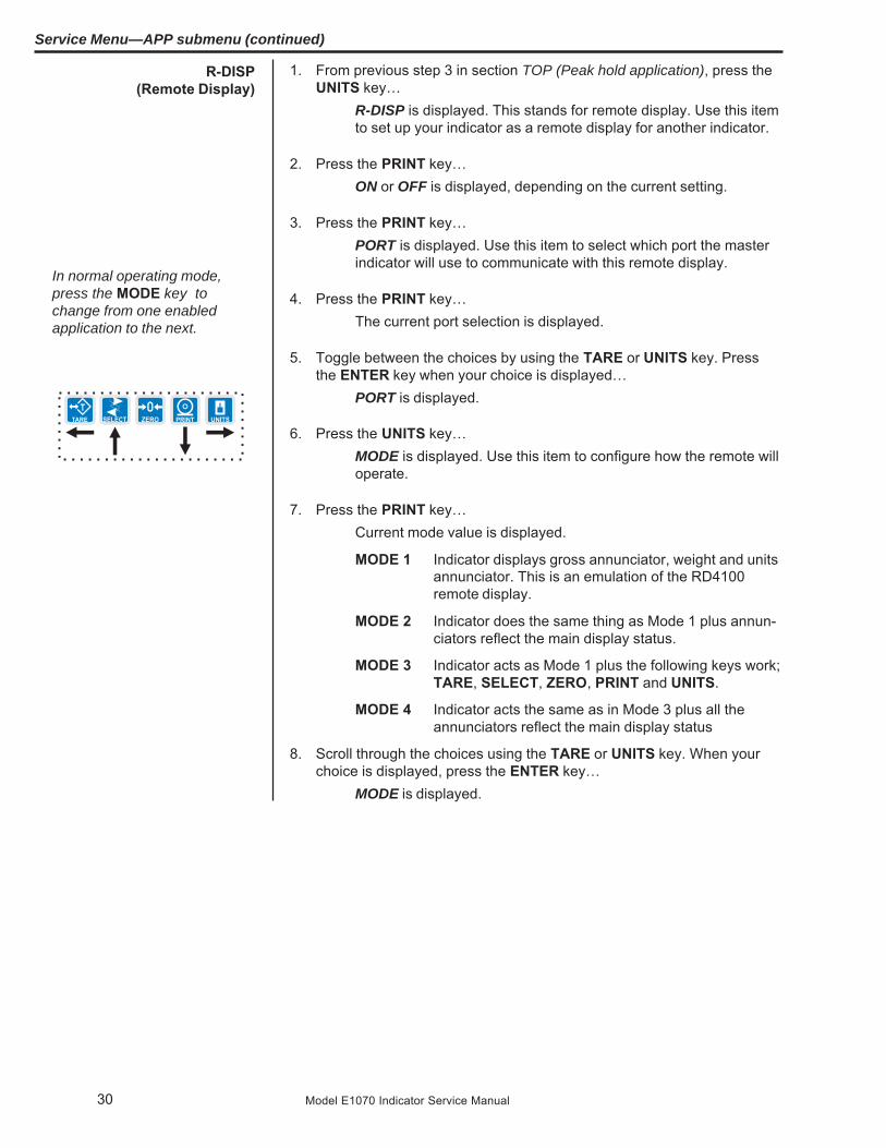
1. From previous step 3 in section TOP (Peak hold application), press theUNITS key…
R-DISP is displayed. This stands for remote display. Use this itemto set up your indicator as a remote display for another indicator.
2. Press the PRINT key…ON or OFF is displayed, depending on the current setting.
3. Press the PRINT key…PORT is displayed. Use this item to select which port the masterindicator will use to communicate with this remote display.
4. Press the PRINT key…The current port selection is displayed.
5. Toggle between the choices by using the TARE or UNITS key. Pressthe ENTER key when your choice is displayed…
PORT is displayed.
6. Press the UNITS key…MODE is displayed. Use this item to configure how the remote willoperate.
7. Press the PRINT key…Current mode value is displayed.
MODE 1 Indicator displays gross annunciator, weight and unitsannunciator. This is an emulation of the RD4100remote display.
MODE 2 Indicator does the same thing as Mode 1 plus annun-ciators reflect the main display status.
MODE 3 Indicator acts as Mode 1 plus the following keys work;TARE, SELECT, ZERO, PRINT and UNITS.
MODE 4 Indicator acts the same as in Mode 3 plus all theannunciators reflect the main display status
8. Scroll through the choices using the TARE or UNITS key. When yourchoice is displayed, press the ENTER key…
MODE is displayed.
R-DISP(Remote Display)
Service Menu—APP submenu (continued)
In normal operating mode,press the MODE key tochange from one enabledapplication to the next.

31Model E1070 Indicator Service Manual
1. Press the SELECT key repeatedly until…R-DISP is displayed.
2. Press the UNITS key…GENRAL is displayed. This is the general weighing application.Repeat steps 2-9 from the ACC (Accumulator application) sectionto set up the General weighing application. This is the defaultapplication for the indicator upon arrival from the factory.
3. Press the SELECT key…GENRAL is displayed.
4. Press the ESC key to exit the Service menu…SAVE is displayed.
5. Press ENTER to save your changes or press ESC to abort any changesmade in the Service menu…
BUSY flashes until the indicator returns to normal operationmode.
This completes the APP menu.
GENRAL(General Weighing Application)
Service Menu—APP submenu (continued)

32 Model E1070 Indicator Service Manual
The first three numbers are the sequence of the print commands.The last two characters are the hexadecimal number for the printcommand.
Use the keys as described in Figure 7 to scroll through the se-quence and change the hex. character value.
Figure 7Key legend for hex editing
TARE key- moves to the previous sequence numberSELECT key - increments hex character upZERO key- Toggles between first and second hex digitPRINT key- decrements hex character downUNITS key- moves right through the print stringENTER key- Accepts print string and exits edit modeON/OFF key- A short key press inserts a new character in front
of the displayed character. Press and hold todelete the currently displayed hex character.
Hex values of 7F (127 decimal) and below are printable charactersand can be seen in Table 1. Hex values from 80 (128 decimal) toFF (255 decimal) is for print command tokens and can be seen inTable 2. See note at left.
The default print formats for each application is shown on the nextpage.
Extra Info:Print Format Editing
FF is the hex. value for End ofString (EOS). When this valueis entered in a print format, anyvalues beyond this in thesequence are ignored and thedisplay will wrap back to the001 item.
You can overwrite the FF valueand use up to the maximumstring length if so desired. Inthe E1070 the maximumsequence length is 256.However, the last character inthe print format must be FF. Besure to add the FF character ifit is removed.

33Model E1070 Indicator Service Manual
Print Formats 1-8 are for the Zebra Thermal printer. See examples on thefollowing pages.
Print Formats 9-15 are for a standard ASCII characters for use with dotmatrix printer.
Print Formats 9 & 10G 123456 lb
{ACT}{DSP}{UN}<CR><LF>{EOS}
Accumulator (Print Format 11), Batching (12) and Checkweigher (13)all use the following:
G 123456 lb
{ACT}{DSP}{UN}<CR><LF>{EOS}
Counting, Print Format 14Piece Count: 48
Piece Count: {CNT}<CR><LF>{EOS}
Peak Print Format 15123456 lb
{PWT} {UN}<CR><LF>{EOS}
Remote Display Print Format 16G 123456 lb
{ACT} {DSP} {UN}<CR><LF>{EOS}
The following are the default print formats are for the corresponding “Mode”setting in the serial port configuration menu.17 Port 1 Enquire (HEX05)18 Port 1 Broadcast19 Port 1 RD410020 Port 2 Enquire (HEX05)21 Port 2 Broadcast22 Port 2 Remote display
G 123456 lb
{ACT} {DSP} {UN}<CR><LF>{EOS}

34 Model E1070 Indicator Service Manual
Format 1, 2 & 3
Time Date
G Gross Weight
T Tare Value
N Net Weight
Format 1 label 1.25” Wide x 1.00” LongFormat 2 label 2.50” Wide x 4.00” LongFormat 3 label 4.00” Wide x 6.00” Long
Print Format 4, same as above with barcode.
Label Size:2.50” Wide4.00” Long
Print Formats 5, 6 & 7
Time Date
PLU Totals Information
Gross Total Accumulator
Format 5 label 1.25” Wide x 1.00” LongFormat 6 label 2.50” Wide x 4.00” LongFormat 7 label 4.00” Wide x 6.00” Long
Print Format 8, same as above with barcode.
Label Size2.50” Wide4.00” Long
Thermal Labels PrintFormats

35Model E1070 Indicator Service Manual
Table 1Printable characters chart

36 Model E1070 Indicator Service Manual
Table 2Printing commands chart
Dec HEX Token Application Group Parameter128 80 GWT(,n) Gross Weight [1] Weight OPTIONAL, (ASCII)
Range: (‘2’-‘9’), Indicator Default: ‘6’129 81 NWT(,n) Net Weight [1] Weight OPTIONAL, (ASCII)
Range: (‘2’-‘9’), Indicator Default: ‘6’131 83 SAT(,n) Semi-Auto Tare [1] Weight OPTIONAL, (ASCII)
Range: (‘2’-‘9’), Indicator Default: ‘6’132 84 UN Units Weight135 87 ID Scale Serial Number Misc136 88 TIM,x Time Time MANDATORY (DECIMAL)
Range: (0-2), Editor Default:10= Format as set/active in indicator1= hh:mm2= hh:mm AM/PM
137 89 DAT,x Date Date MANDATORY, (DECIMAL)Range: (0-4), Editor Default:10= Format as set/active in indicator1= MM/DD/YY2= MM/DD/YYYY3= DD/MM/YY4= DD/MM/YYYY
138 8A TTV,n Target Value Trip MANDATORY, (HEX #s)Range: (‘31’-‘33’), Editor Default: ‘1’For target weights
142 8E CLA(,n) Checkweigher Checkweight OPTIONAL, (ASCII)‘Low Accept’ value [1] Range: (‘2’-‘9’), Indicator Default: ‘6’
143 8F CHA(,n) Checkweigher Checkweight OPTIONAL, (ASCII)‘High Accept’ value [1] Range: (‘2’-‘9’), Indicator Default: ‘6’
144 90 RAV,n Active Recipe Recipe MANDATORY, (HEX #s)Ingredient x ‘Actual’ value Range: (‘31’-‘38’), Editor Default: ‘1’
For target weights in recipe145 91 RTV,n Active Recipe Recipe MANDATORY, (HEX #s)
Ingredient x ‘Target’ value Range: (‘31’-‘38’), Editor Default: ‘1’For preact values in recipe
146 92 RPV,n Active Recipe Recipe MANDATORY, (HEX #s)Ingredient x ‘Preact’ value Range: (‘31’-‘38’), Editor Default: ‘1’
For target weights in recipe147 93 RIU,n Active Recipe Recipe MANDATORY, (HEX #s)
Ingredient x units Range: (‘31’-‘38’), Editor Default: ‘1’For ingredient units (lb or kg for weightbased ingredients; sec for time basedingredients; cnts or gallons for pulsecounter based ingredients). To beprinted after the target or actual ingredi-ent value.
148 94 PCE Piece Weight Count149 95 CNT Current Count Value Count151 97 GTO Gross Accumulator Weight153 99 STO Net Accumulator Weight155 9B PLU PLU NumberData PLU

37Model E1070 Indicator Service Manual
Dec HEX Token Application Group Parameter156 9C DES PLU ID PLU162 A2 DIS Remote Display Status Miscellaneous170 AA VER Software Version Number Miscellaneous173 AD WST Weight Steady Weight178 B2 PUP Tare associated with the PLU PLU184 B8 PUT PLU Totals Information PLU188 BC PCT PLU Count Total PLU189 BD LST Net Accumulator PLU190 BE LGT Gross Accumulator PLU200 C8 DSP(,n) Print the displayed weight Weight OPTIONAL, (ASCII)
Range: (‘2’-‘9’), Indicator Default: ‘6’215 D7 NULL Null Token Strings216 D8 ACT Print the active value (‘G’ for
gross, ‘N’ for net, ‘T’ for tare) Weight242 F2 PWT Peak Hold Weight value Weight253 FD HEX,xx Following number will be Hex-Codes MANDATORY, (ASCII-HEX)
transmitted by value. Also, Range: (00 – FF), Editor Default: 00use this selection totransmit a NUL as well.
254 FE TEX Reserved for future useas a ‘token extender’ -----
255 FF EOS End of String String
Notes:These tokens can be optionally followed by an ASCII 2 to 9 to specify the number of weight digits (includingdecimal point). If no specifier is given it defaults to 6 digits (+ decimal point) (equivalent to ASCII 6).
Further, parameter values may be ASCII digits (i.e. range ‘0’ thru ‘9’) or DECIMAL values (i.e. range 0 thru 255). Inall cases, parameters consume one byte. In the term/token table parameters are indicated as follows:Optional, (ASCII) - (,n)Optional, (Decimal) - (,x)Mandatory, (ASCII) - ,nMandatory, (Decimal) - ,x

38 Model E1070 Indicator Service Manual
SERIAL submenu
Follow these steps to access each item in the SERIAL menu and to under-stand what they do and how to set them:
1. Access the Service menu…CAL is displayed.
2. Press the UNITS key repeatedly until…SERIAL is displayed.
3. Press the PRINT key…PORT 1 is displayed.
4. Scroll through the other choices, PORT 2 and STRING, by using theTARE or UNITS key and press the ENTER key to accept the displayedchoice. If you choose PORT 1 or PORT 2, continue with the rest of thisstep. If you choose STRING, go to the section STRING (Custom printformats).All the port configuration items are identical for Port 1 and Port 2except port 1 has two additional TYPE selections (RS-485 and485HD). Use the following steps to configure each port.
BAUD is displayed.
Use this item to set the baud rate.
The next section of the Service menu is the SERIAL submenu. See Figure8. This menu lets you choose the configure the serial ports and createcustom print formats #1-10.
Figure 8SERIAL (serial communication) submenu
Port 1 or Port 2
The default serial port param-eters are 9600 baud, 8 dat-abits, no parity and 1 stop bit.
Stop bits for the serialcommunication are preset to1 stop bit. This is not config-urable.

39Model E1070 Indicator Service Manual
5. Press the PRINT key …Current baud rate is displayed. Choices are from 300 to 115,200.Default is 9600.
6. Scroll the choices by using the TARE or UNITS key and press theENTER key to accept the displayed choice. .
BAUD is displayed.
1. Press the UNITS key…D-BITS is displayed. Use this item to set the data bits value.
2. Press the PRINT key…7 or 8 is displayed.
3. Toggle between the choices by using the TARE or UNITS key andpress the ENTER key to accept the displayed choice. .
D-BITS is displayed.
1. Press the UNITS key…PARITY is displayed. Use this item to set parity.
2. Press the PRINT key…NONE, ODD or EVEN is displayed.
3. Scroll through the choices by using the TARE or UNITS key and pressthe ENTER key to accept the displayed choice. .
PARITY is displayed.
1. Press the UNITS key…C-TROL is displayed. Use this item to set parity. Use this item toset the handshake control.
2. Press the PRINT key…NONE, RTS or SOFT (Xon/Xoff) is displayed.
3. Scroll through the choices by using the TARE or UNITS key and pressthe ENTER key to accept the displayed choice. .
C-TROL is displayed.
D-BITS(Data bits)
C-TROL(Handshakecontrol)
PARITY(Parity setting)
BAUD(Baud rate)
Service Menu—SERIAL submenu (continued)

40 Model E1070 Indicator Service Manual
ENQ
1. Press the UNITS key…TYPE is displayed. Use this item to set the port mode.
2. Press the PRINT key…Current setting is displayed. These are the choices you scrollthrough in step 3:
ENQ This stands for enquire. When an appropriate enquirecode is sent to the indicator, the configured printformat is sent through the port.
B-CAST This stands for broadcast. If this is enabled, theindicator will send out the configured print format atthe configured rate whenever scale weight is stable.
SMA Scale Manufacturer’s Association protocol. See Table3.
R-DISP This stands for remote display. If this is enabled, youcan pick the type of remote display info to send andthe rate the info is sent. This choice sends info con-tinuously, regardless of the motion on the scale.
RS-485 SMA protocol over an RS-485 multidrop connection(Port 1 only)
485 HD SMA protocol over an RS-485 half-duplex multidropconnection (Port 1 only)
3. Scroll through the choices by using the TARE or UNITS key and pressthe ENTER key to accept the displayed choice. .
If you pick:
ENQ go to ENQ section belowB-CAST go to B-CAST section belowSMA go to SMA section belowR-DISP go to R-DISP section belowRS-485 (for port 1 only) go to RS-485 section below485 HD go to 485 HD section below
1. With ENQ displayed, press the PRINT key. There are 3 items that canbe changed when the Enquire mode is selected. Use the TARE and/orUNITS keys to scroll through the following items:
P-ft Change the print format(s) that will be printed when theenquire character is received through the serial port.Press the PRINT key with P-ft displayed. PftX is dis-played. The X stands for the current print format setting.Press ENTER to accept this format or key in a newformat or formats and press the ENTER key to accept.
POLL Change the ASCII character that the indicator willrespond to. Press the PRINT key with POLL displayed.The current character represented as a decimal number
TYPE(Serial port mode )
Service Menu—SERIAL submenu (continued)
Choosing R-DISP in the Serialmenu will configure the HOSTindicator. The remote displayindicator is configured byselecting the R-DISP applica-tion in the APP submenu.

41Model E1070 Indicator Service Manual
will be displayed. (Example: for a carriage return (Hex:0D) 13 will be displayed) Press the ENTER key toaccept the character that is displayed or key in thedecimal equivalent for the desired character and pressthe ENTER key.
Stable Change the stability setting for the Enquire mode. Thiscan be set to YES which will require that there is nomotion on the scale for a response to be sent or NO.Press the PRINT key with Stable displayed. Either YESor NO will be displayed depending on the previoussetting. Use the TARE or UNITS key to toggle betweenYES or NO. When the desired setting is displayed usethe ENTER key to accept.
When all three items have been set correctly, press the SELECT key to exitthe Enquire submenu.
Service Menu—SERIAL submenu (continued)

42 Model E1070 Indicator Service Manual
SMA
B-CAST
The A and B commands arerelated. An A command mustbe sent before the first Bcommand is sent. Multiple Bcommands can be sent afterthe A command and each onewill return a different piece ofdata. If a B command returns a‘?’ or END response, an Acommand is needed to resetthe B command
1. With B-CAST displayed, press the PRINT key…Current update rate is displayed. Choices are 1/sec, 2/sec, 5/sec,and 10/sec.
2. Scroll through the choices using the TARE or UNITS key. Press theENTER key when your choice is displayed…
PFTX is displayed. The X stands for the current print formatsetting.
3. Press the ENTER key to accept this format or key in a new format orformats and press the ENTER key to accept…
B-CAST is displayed.
1. With SMA displayed, press the PRINT key…The SMA protocol is selected and TYPE is displayed.
Table 3SMA protocol
Command Sentto Indicator Result<LF>W<CR> Weight returned if no motion. Dashes
displayed if motion on scale.
<LF>P<CR> Weight returned if no motion. Dashesdisplayed if motion on scale.
<LF>Z<CR> Scale zeros itself if no motion. Dashesdisplayed if motion on scale.
<LF>T<CR> Scale tares itself and returns G or N weightif no motion. Dashes displayed if motion onscale.
<LF>T<xxxxxx.xxx><CR> Scale attempts to take the <xxxxxx.xxx>data as the tare weight and returns G or Nweight if no motion. Dashes displayed ifmotion on scale.
<LF>M<CR> Returns the tare weight if no motion.Dashes displayed if motion on scale.
<LF>C<CR> Clears the tare weight if no motion.Dashes displayed if motion on scale.
<LF>U<uuu><CR> Sets the unit of measure label to uuuExample: lb_ ( _ =space)Works for lb or kg only, not custom units.
<LF>D<CR> Runs scale diagnostics and sends diag-nostic message
<LF>A<CR> Sends the SMA compliance level. Seenote at left.
Service Menu—SERIAL submenu (continued)

43Model E1070 Indicator Service Manual
<LF>B<CR> 1st B sent returns manufacturer2nd B sent returns model software #3rd B sent returns the software revisionlevel4th B sends an END5th or more sends a ?
<LF>U<CR> Toggles the units of measure if no motion.Dashes displayed if motion on scale.
<LF>I<CR> Sends the SMA compliance level asSMA:compliance level / revision level
<LF>N<CR> 1st N sends the scale type; S or C.TYP:S = scale, TYP:C = Classifier
2nd N sends CAP:uuu:c..c:n:d whereuuu = unit of measurec..c = full capacity of this range. If multi-interval is not enabled, this is the scalecapacity.n = Least significant count-by digitd = decimal point position:
0 = none1 = XXXX.X2 = XXX.XX3 = XX.XXX…etc.
3rd N sends the following if multi-interval isenabled: the same info as the 2nd Nexcept for the upper range of the multi-interval.3rd N sends the following if the multi-interval is disabled: List of the SMA level 2commands that are implemented:CMD:PTMCU
Last valid N sends ENDSubsequent N commands will return a ‘?’response.
ESC This reboots the indicator
<LF>XP<num><CR> Request a print format to be printed, 0-10
<LF>XT<cutoff><xxxx.xx><CR> Attempts the take <xxxx.xx> as the weightSet a cutoff/trip weight. for cutoff #<cutoff>. The indicator will
respond with:<LF>XT<cutoff><xxxx.xx>Set<CR> if thecutoff weight was accepted or<LF>XTFail<CR> if the cutoff weight couldnot be set to the value specified.Cutoff =1-3. Weight limited to scale cap.
Service Menu—SERIAL submenu (continued)
The I and N commands arerelated. An I command must besent before the first N com-mand is sent. Multiple Ncommands can be sent afterthe I command and each onewill return a different piece ofdata. If an N command returnsa ‘?’ or END response, an Icommand is needed to resetthe N command
ESC is the only command thatthe scale receives which doesnot follow the standard<LF>c<CR> protocol and doesnot have a response.

44 Model E1070 Indicator Service Manual
<LF>XT<cutoff><CR> The indicator will respond with:Request a cutoff/trip weight. <LF>XT<cutoff><xxxx.xx><CR> where
<xxxx.xx> is the weight for cutoff number<cutoff>.or<LF>XTError<CR> if the cutoff numberspecified is invalid.Cutoff =1-3. Weight limited to scale cap.
<LF>XC<channel><CR> Attempts to set the PLU channel toSet the PLU channel. <channel>. The indicator responds with:
<LF>XC<channel>Set<CR> if the channelnumber was valid.Or<LF>XCFail<CR> if the channel numberwas invalid. Valid channel numbers are 0-10.
<LF>XC<CR> The indicator will respond with:Request the PLU current <LF>XC<channel><CR>channel.
<LF>XI<id><CR> The indicator will respond with:Set the ID number of <LF>XI<id>Set<CR>current PLU channel.
<LF>XI<CR> The indicator will respond with:Request the id number of <LF>XI<id><CR>the current PLU channel.
<LF>XK<lower limit>,<upper The indicator will respond with:limit><CR> <LF>XK<lower limit>,<upperSet the checkweigher lower limit>Set<CR> if the limits where setand upper limit. successfully.
Or<LF>XKFail<CR> if the limit values wereinvalid.
<LF>XK<CR> The indicator will respond with:Request the checkweigher <LF>XK<lower limit>,<upper limit><CR>lower and upper limit values.
<LF>XE<pcwt><CR> The indicator will respond with:Set the piece weight for the <LF>XE<pcwt>Set<CR>Counting application.
<LF>XE<CR> The indicator will respond with:Request the piece weight <LF>XE<pcwt><CR>for the Counting application.
Service Menu—SERIAL submenu (continued)

45Model E1070 Indicator Service Manual
1. With R-DISP displayed, press the PRINT key…Current setting is displayed. Use this item to choose what style ofoutput you want for this indicator as a master indicator going to aremote display. Choices are RD4100, RDAPP1, RDAPP2,RDAPP3 and RDAPP4.
RD4100 Select this to emulate output to an RD-4100. You canpick a print format to be sent to the remote display. Ifyou pick format #0 a default G XXXXXX lb format willbe sent.
RDAPP1 Select this to send G XXXXXX lb
RDAPP2 Select this to send the same as RDAPP1 + annuncia-tors
RDAPP3 Select this to send the same as RDAPP1 + will acceptthe keys presses from the remote (TARE, SELECT,ZERO, PRINT, UNITS)
RDAPP4 Select this to send the same as RDAPP2 + acceptsthe keys presses from the remote (TARE, SELECT,ZERO, PRINT, UNITS)
2. Scroll through the choices using the TARE or UNITS key. Press theENTER key when your choice is displayed…
Current update rate is displayed. Choices are 1/sec, 2/sec, 5/sec,and 10/sec. This is the update rate
3. Scroll through the choices using the TARE or UNITS key. Press theENTER key when your choice is displayed…
If you chose RD4100: PFTX is displayed. The X stands for thecurrent print format setting. Press theENTER key to accept this format or key ina new format or formats and press theENTER key to accept.
Otherwise: R-DISP is displayed.
R-DISP
Service Menu—SERIAL submenu (continued)

46 Model E1070 Indicator Service Manual
This section applies only if you are configuring Port 1:
1. With RS485 displayed, press the PRINT key.adr XX is displayed. This is the slave address of the indicator.
2. Press the ENTER key to accept the displayed address or key in a newvalue then press ENTER.
RS-485 mode is very similar to SMA mode, but the transmission isover an RS-485 multidrop connection instead of over RS-232hardware. There is a slight difference in the protocol as well. Themaster must send the slave address as part of the request. Forexample, instead of sending:
<LF>W<CR> to the indicator,
<LF><sadd>W<CR> must be sent.
<sadd> is the slave address of the indicator that the master wantsa response from. If the slave address sent to an indicator matchesthe configured slave address, the indicator will respond with theslave address as part of the response. All SMA responses beginwith a <LF>. The slave address will be the character immediatelyfollowing the <LF>.
1. With 485 Hd displayed, press the PRINT key.Adr XX is diplayed. This is the slave address of the indicator
2. Press the ENTER key to accept the displayed address or key in a newvalue then press ENTER.
485 Hd mode is essentially the same as RS-485 mode, but thetransmission is over a Half-Duplex (2-wire connection) instead ofthe Full-Duplex connection that must be in place for RS-485mode. The protocol is exactly the same a RS-485 mode (the slaveaddress is sent with the commands and responses). See the RS-485 description (above) for complete details.
When you are done with the TYPE menu item and TYPE is displayed, doone of the following:
Return to normal operation—
1. Press the ESC key…SAVE is displayed.
2. Press ESC to abort the save and return to normal operation modeORPress the ENTER key to save the changes and return to normal opera-tion mode
ORContinue with the Serial submenu—
1. Press the UNITS key to move on to the next Serial menu item which isA-PRNT.
RS-485
Service Menu—SERIAL submenu (continued)
485 Hd

47Model E1070 Indicator Service Manual
A-PRINT(Autoprint minimum
trigger weight)
1. Press the UNITS key…A-PRNT is displayed. Use this item to set a minimum weight, as apercentage of capacity, under which the indicator will send out theconfigured print format when the weight is stable (no motion). Seta value of 0 to disable the autoprint function.
2. Press the PRINT key…Current setting is displayed.
3. Key in your weight choice and press the ENTER key to accept…A-PRNT is displayed.
1. Press the UNITS key…LEAD-0 is displayed. Use this item to turn a leading zero on or offfor all system variables.
2. Press the PRINT key…ON or OFF is displayed.
3. Toggle between the choices by using the TARE or UNITS key and pressthe ENTER key to accept the displayed choice. .
LEAD-0 is displayed.
4. Press the SELECT key…PORT 1 or 2 is displayed.
5. Repeatedly press the UNITS key until…STRING is displayed.
LEAD-0(Leading zero )
Service Menu—SERIAL submenu (continued)
48 Model E1070 Indicator Service Manual
Use the String item to create customized print formats. The default printformat is always = 0 and it is edited under the APP menu item.
Use the STRING menu to create formats #1-10. These formats are calledfrom application specific settings or from Serial menu item settings.
1. Press the PRINT key…1 is displayed. This is the print format number.
2. Scroll through the list of 1-10 using the TARE or UNITS key and pressENTER to select the displayed choice…
The current destination is displayed. This may be:Port 1, serial port #1
Port 2, serial port #2
TCPIP1 if you want to send the format(s) through network connec-tion #1 (net1 must be configured as Enet1 or Enet4)
TCPIP2 if you want to send the format(s) through network connec-tion #2 (net2 must be configured as Enet1 or Enet4)
SMTP1 if you want to send the format(s) as an email throughnetwork connection #1 (net1 must be configured as Enet1 orEnet4)
SMTP2 if you want to send the format(s) as an email throughnetwork connection #2 (net2 must be configured as Enet1 orEnet4)
3. Scroll through the choices shown above by using the TARE or UNITSkey and press the ENTER key to accept the displayed choice…
A string is displayed. Refer to the section Extra Info: Print FormatEditing to understand how to edit strings.
4. When you are done editing a string press the ENTER key…The print format number is displayed.
5. Do 6a or 6b:6a. Repeat steps 2-6.6b. Press the SELECT key to return to the SERIAL display…
SERIAL is displayed. This completes the SERIAL submenu.
7. Press the UNITS key to go to the TEST submenuORpress ESC to return to normal operation mode…
If you press ESC, SAVE is displayed.
8. Press ENTER to save the changes or the ESC key to abort the saveprocess and return to normal operating mode.
STRING(Custom print formats)
Service Menu—SERIAL submenu (continued)
49Model E1070 Indicator Service Manual
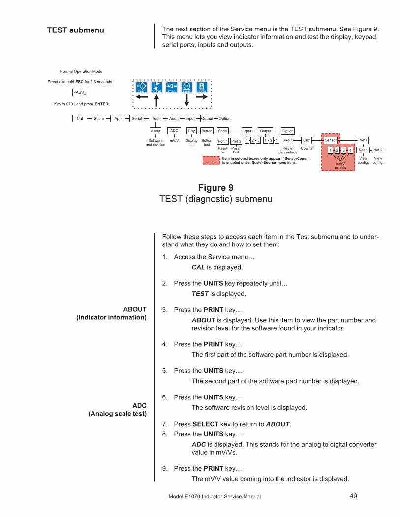
TEST submenu The next section of the Service menu is the TEST submenu. See Figure 9.This menu lets you view indicator information and test the display, keypad,serial ports, inputs and outputs.
Figure 9TEST (diagnostic) submenu
ABOUT(Indicator information)
Follow these steps to access each item in the Test submenu and to under-stand what they do and how to set them:
1. Access the Service menu…CAL is displayed.
2. Press the UNITS key repeatedly until…TEST is displayed.
3. Press the PRINT key…ABOUT is displayed. Use this item to view the part number andrevision level for the software found in your indicator.
4. Press the PRINT key…The first part of the software part number is displayed.
5. Press the UNITS key…The second part of the software part number is displayed.
6. Press the UNITS key…The software revision level is displayed.
7. Press SELECT key to return to ABOUT.8. Press the UNITS key…
ADC is displayed. This stands for the analog to digital convertervalue in mV/Vs.
9. Press the PRINT key…The mV/V value coming into the indicator is displayed.
ADC(Analog scale test)

50 Model E1070 Indicator Service Manual
10. Press the SELECT…ADC is displayed.
11. Press the UNITS key…DISP is displayed. This is the display test item.
12. Press the PRINT key to perform a dynamic test of the display.
13. Press the ESC key once to stop the dynamic test…
The display may flash one or two more times and then DISP willbe displayed.
14. Press the UNITS key…BUTTON is displayed. This is the button test item.
15. Press the PRINT key to perform a button test. Each key you press willbe reflected on the display screen to confirm the button is functioningcorrectly.
16. Press the ESC key to stop the button test.BUTTON is displayed.
17. Press the UNITS key…SERIAL is displayed. This is the serial test item.
18. Press the PRINT key to access the serial test.PORT1 is displayed. If you jumper the transmit and receive lineson the serial port and press the PRINT key, the display shouldshow PASS. If there is a problem the display will show FAIL.
Repeat this for PORT 2.
19. Press SELECT key to return to the SERIAL item…SERIAL is displayed.
DISP(Display test)
BUTTON(Key test)
SERIAL(Serial port test)
Service Menu—TEST submenu (continued)

51Model E1070 Indicator Service Manual
INPUT(Input test)
OUTPUT(Output test)
17. Press the UNITS key…INPUT is displayed. This is the input test item.
18. Press the PRINT key to access the test.1 2 3 is displayed. 1 stands for input 1, etc.
19. If you jumper pins 1 and 2 of the I/O connector on the bottom of theindicator…
1 becomes 0 until the jumper is removed.
To test input 2, jumper pins 1 and 3. 2 becomes 0 until the jumperis removed.
To test input 3, jumper pins 1 and 4. 3 becomes 0 until the jumperis removed.
20. Press the SELECT key…INPUT is displayed.
21. Press the UNITS key…OUTPUT is displayed. This is the output test item.
22. Press the PRINT key to access the test.1 is displayed. This stands for output 1.
23. Press the PRINT key…The display toggles between ON and OFF. This will toggle theoutput off and on. Monitor the output to see that it is turning offand on. Use a Trips Interface Unit (TIU3) or other output device.
24. Stop the test by pressing the SELECT key…1 is displayed.
25. Press the UNITS key…2 is displayed.
26. Repeat steps 23 and 24 for outputs 2 and 3…27. Press the SELECT key…
OUTPUT is displayed.
28. Press the UNITS key…OPTION is displayed.
29. Press the PRINT key…A-OUT is displayed. This stands for the analog output test.
30. Press the PRINT key…A numeric entry screen is displayed.
OPTION(Option tests)
A-OUT test
Service Menu—TEST submenu (continued)
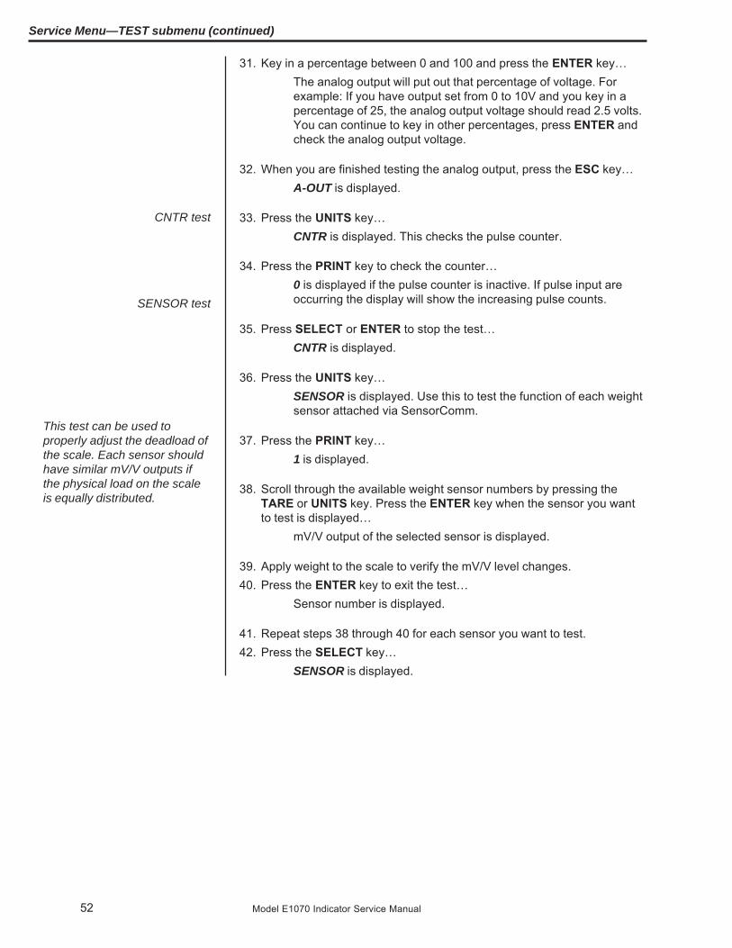
52 Model E1070 Indicator Service Manual
31. Key in a percentage between 0 and 100 and press the ENTER key…The analog output will put out that percentage of voltage. Forexample: If you have output set from 0 to 10V and you key in apercentage of 25, the analog output voltage should read 2.5 volts.You can continue to key in other percentages, press ENTER andcheck the analog output voltage.
32. When you are finished testing the analog output, press the ESC key…A-OUT is displayed.
33. Press the UNITS key…CNTR is displayed. This checks the pulse counter.
34. Press the PRINT key to check the counter…0 is displayed if the pulse counter is inactive. If pulse input areoccurring the display will show the increasing pulse counts.
35. Press SELECT or ENTER to stop the test…CNTR is displayed.
36. Press the UNITS key…SENSOR is displayed. Use this to test the function of each weightsensor attached via SensorComm.
37. Press the PRINT key…1 is displayed.
38. Scroll through the available weight sensor numbers by pressing theTARE or UNITS key. Press the ENTER key when the sensor you wantto test is displayed…
mV/V output of the selected sensor is displayed.
39. Apply weight to the scale to verify the mV/V level changes.40. Press the ENTER key to exit the test…
Sensor number is displayed.
41. Repeat steps 38 through 40 for each sensor you want to test.42. Press the SELECT key…
SENSOR is displayed.
CNTR test
SENSOR test
This test can be used toproperly adjust the deadload ofthe scale. Each sensor shouldhave similar mV/V outputs ifthe physical load on the scaleis equally distributed.
Service Menu—TEST submenu (continued)

53Model E1070 Indicator Service Manual
Service Menu—TEST submenu (continued)
43. Press the UNITS key…NETS is displayed.
44. Press the PRINT key…NET 1 is displayed.
45. Toggle between Net 1 or Net 2 using the TARE or UNITS key and pressPRINT when the network you want to view is displayed.
The first screen of network configuration information is displayed.
46. Repeatedly press the PRINT key to view all the configuration informa-tion. The display will return to NET 1 or NET 2 when you’ve seen all theinformation.
This completes the TEST submenu. Press the SELECT key until TEST isdisplayed and then press the UNITS key to go to the AUDIT submenu
To return to normal weighing mode, press ESC. If you press ESC you will beprompted to save any changes made. Press ESC to abort any changes orpress ENTER to save changes.
NETS test

54 Model E1070 Indicator Service Manual
AUDIT submenu The next section of the Service menu is the AUDIT submenu. See Figure10. This menu lets you view configuration and calibration audit counters.These counters cannot be changed, only viewed.
Figure 10AUDIT submenu
CFG(Configuration audit counter)
Follow these steps to access each item in the AUDIT menu:
1. Access the Service menu…CAL is displayed.
2. Press the UNITS key repeatedly until…AUDIT is displayed.
3. Press the PRINT key…CFG is displayed. This stands for the Configuration audit counter.Use this item to see how many times this indicator has beenconfigured.
4. Press the PRINT key…A number is displayed. This is the number of times this indicatorhas been configured.
5. Press SELECT…CFG is displayed.
6. Press the UNITS key…
CAL is displayed. This stands for the Calibration audit counter.Use this item to see how many times this indicator has beencalibrated.
7. Press the PRINT key…A number is displayed. This is the number of times this indicatorhas been calibrated.
8. Press the SELECT key twice…AUDIT is displayed.
This completes the AUDIT submenu. Press the UNITS key to go to theINPUT submenu or press ESC to return to normal weighing mode.
CAL(Calibration audit counter)

55Model E1070 Indicator Service Manual
The next section of the Service menu is the INPUT submenu. See Figure11. This menu lets you configure the inputs of the indicator.
INPUT submenu
Figure 11INPUT submenu
Follow these steps to access and configure the inputs:
1. Access the Service menu…CAL is displayed.
2. Press the UNITS key repeatedly until…INPUT is displayed.
3. Press the PRINT key…1 is displayed. This stands for input #1. You can scroll to eachinput by using the TARE or UNITS key. When you access eachinput, by pressing the PRINT key, you get to choose from this listof input types:
NONE Input does nothing
ZERO Input zeroes the scale
TARE Input tares the scale
PRINT Input causes the print function to occur
UNITS Input toggles the unit of measure
F1KEY Input performs current F1 function
T.CNCEL Input clears the tare
START Starts a batch/fill if the batching application is active
STOP Stops a batch/fill if the batching application is active

56 Model E1070 Indicator Service Manual
Service Menu—INPUT submenu (continued)
4. Scroll through the choices by using the TARE or UNITS key and pressthe ENTER key to accept the displayed choice…
The input #is displayed.
5. Repeat steps 3 and 4 for each input.6. Press the SELECT key to return to the INPUT menu item…
INPUT is displayed.
This completes the INPUT submenu. Press the UNITS key to go to theOUTPUT submenu or press ESC to return to normal weighing mode.
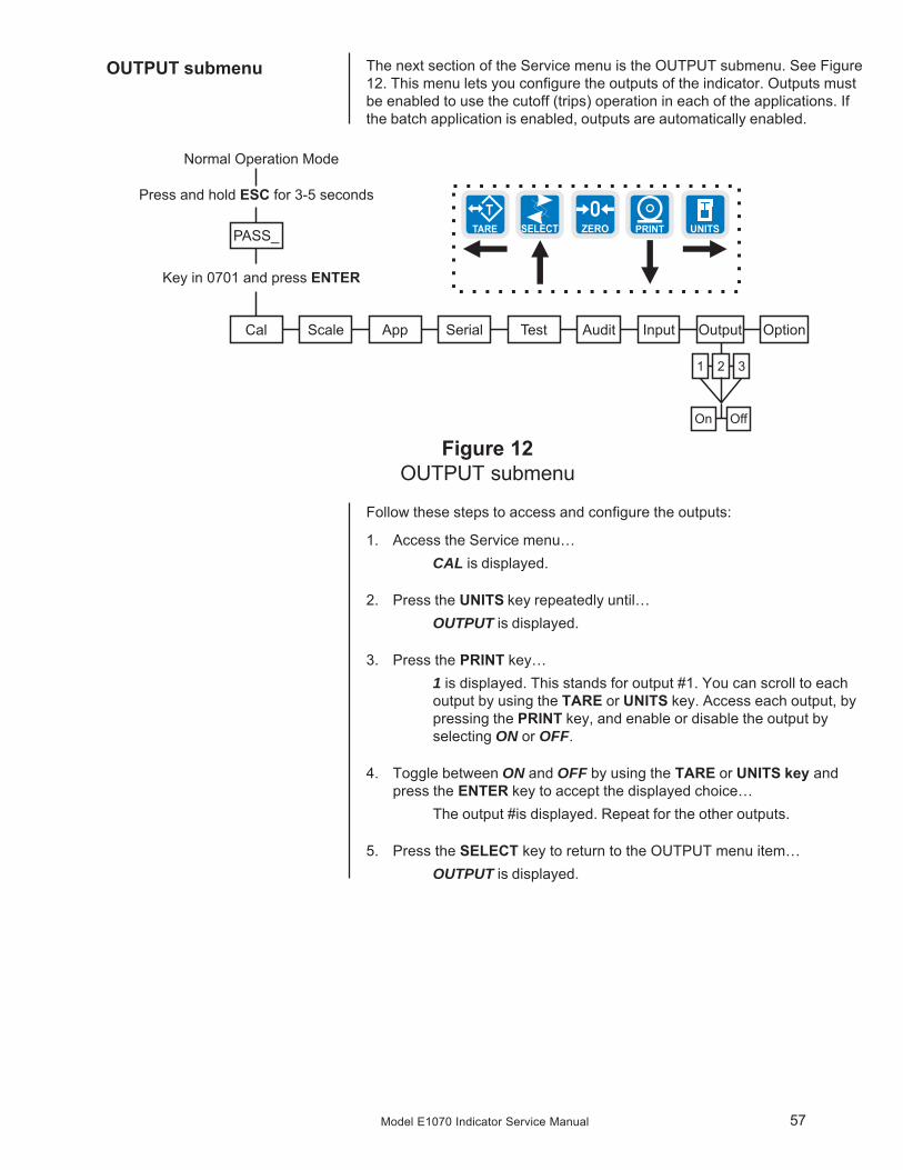
57Model E1070 Indicator Service Manual
The next section of the Service menu is the OUTPUT submenu. See Figure12. This menu lets you configure the outputs of the indicator. Outputs mustbe enabled to use the cutoff (trips) operation in each of the applications. Ifthe batch application is enabled, outputs are automatically enabled.
OUTPUT submenu
Figure 12OUTPUT submenu
Follow these steps to access and configure the outputs:
1. Access the Service menu…CAL is displayed.
2. Press the UNITS key repeatedly until…OUTPUT is displayed.
3. Press the PRINT key…1 is displayed. This stands for output #1. You can scroll to eachoutput by using the TARE or UNITS key. Access each output, bypressing the PRINT key, and enable or disable the output byselecting ON or OFF.
4. Toggle between ON and OFF by using the TARE or UNITS key andpress the ENTER key to accept the displayed choice…
The output #is displayed. Repeat for the other outputs.
5. Press the SELECT key to return to the OUTPUT menu item…OUTPUT is displayed.

58 Model E1070 Indicator Service Manual
The next section of the Service menu is the OPTION submenu. See Figure13. This menu lets you configure analog output, a pulse counter, Sensor-Comm and networks.
OPTION submenu
Figure 13OPTION submenu

59Model E1070 Indicator Service Manual
Follow these steps to access and configure the options:
1. Access the Service menu…CAL is displayed.
2. Press the UNITS key repeatedly until…OPTION is displayed.
3. Press the PRINT key…A-OUT is displayed. This is the analog output menu item.
4. Press the PRINT key…ON or OFF is displayed. ON enables analog output. OFF disablesit.
5. Toggle between ON and OFF by using the TARE or UNITS key andpress the ENTER key to accept the displayed choice…
If you pick OFF, A-OUT is displayed and you can continue to thenext menu item, CNTR.
If you pick ON, continue to step 6.
6. Press the PRINT key…LO is displayed. Use this to set the weight which is equal to thelowest analog output.
7. Press the PRINT key…Current value is displayed.
8. Key in a value and press ENTER…LO is displayed.
9. Press the UNITS key…HI is displayed. This is the weight at which the analog output willbe at maximum.
10. Press the PRINT key…Current value is displayed.
11. Key in a value and press ENTER…HI is displayed.
12. Press the UNITS key…BASIS is displayed. Use this to choose if output is based on grossor net weight.
13. Press the PRINT key…GROSS or NET is displayed.
14. Toggle between the choices by using the TARE or UNITS key. PressENTER when your choice is displayed…
BASIS is displayed.
A-OUT(Analog Output)
Service Menu—OPTION submenu (continued)

60 Model E1070 Indicator Service Manual
15. Press the UNITS key…CAL is displayed. Use this to calibrate the analog output.
16. Press the ENTER key…ZERO is displayed. Use this to set the analog output zero point.
17. Press the PRINT key…ADJUST is displayed. Use this to adjust the zero output up ordown by pressing the SELECT (up) or PRINT (down) key. Eachkey press changes the output by 0.25% of available range for theoutput.
When you are done, press the ENTER key and go to step 21.
If you need to change the zero output by a custom amount, pressthe ENTER key and go to step 18.
18. To change the zero output by a custom amount, from the ADJUSTdisplay, press the UNITS key…
CUST. is displayed.
19. Press the PRINT key…A numeric entry screen appears.
20. Enter a custom amount, in percentage of available range for the output,and press the ENTER key…
CUST. is displayed.
21. Press the SELECT key…ZERO is displayed.
22. Press the UNITS key…SPAN is displayed. Use this to set the analog output span point.
23. Repeat steps 17-20 to adjust span.24. Repeatedly press the SELECT key until…
A-OUT is displayed.
Service Menu—OPTION submenu (continued)

61Model E1070 Indicator Service Manual
CNTR(Pulse counter )
Optional circuitry required
SENSOR(SensorComm setup)
This section only appears ifSensorComm is chosen as the
scale source
You can key in a value underCOUNT if you wish to pre-loador reload a set number ofpulses into the accumulator.This may be handy if you’veexperienced a pulse counterinput error.
Service Menu—OPTION submenu (continued)
Follow these steps to configure the pulse counter.1. Press the UNITS key…
CNTR is displayed. This stands for the pulse counter option. Usethis item to enable and enter a factor for converting pulses intoyour unit of measure.
2. Press the PRINT key…ON or OFF is displayed.
3. Toggle between the choices by pressing the TARE or UNITS key. Whenyour choice is displayed, press the ENTER key…
RATIO or COUNT is displayed. RATIO lets you enter a valueequal to your pulse counter’s pulses per unit of volume. COUNTlets you view the actual accumulated pulse count.
4. Toggle between the choices by pressing the TARE or UNITS key. Whenyour choice is displayed, press the ENTER key…
If you pick RATIO, you can key in a factor.
If you pick COUNT, the display shows the accumulated actualpulse counts. See note at left.
In either case, press the ENTER key and the display will return toRATIO or COUNT.
5. Repeatedly press the SELECT key until…CNTR is displayed.
1. Press the UNITS key…SENSOR is displayed. Use this item to configure the Sensor-Comm.
2. Press the PRINT key…GHOST is displayed. Use this to enable or disable Ghost function.
3. Press the PRINT key…ON or OFF is displayed.
4. Toggle between the choices by pressing the TARE or UNITS key. Whenyour choice is displayed, press the ENTER key…
GHOST is displayed.
5. Press the UNITS key…Z.DRIFT is displayed. Use this to set levels of zero drift that willtrip warnings and errors.
6. Press the PRINT key…ENABLE is displayed.
7. Press the PRINT key…ON or OFF is displayed.
62 Model E1070 Indicator Service Manual
8. Toggle between the choices by pressing the TARE or UNITS key. Whenyour choice is displayed, press the ENTER key…
ENABLE is displayed.
9. Press the UNITS key…WARN is displayed. Use this to set the zero drift as a percentageof total capacity which will cause a warning to be logged.
10. Press the PRINT key…Numeric entry screen appears.
11. Enter a number, in percentage of total capacity, and press ENTER toaccept it…
WARN is displayed.
12. Press the UNITS key…ERROR is displayed. Use this to set the zero drift as a percentageof total capacity which will cause an error to be logged.
13. Press the PRINT key…Numeric entry screen appears.
14. Key in a number, in percentage of total capacity, and press ENTER toaccept it…
ERROR is displayed.
15. Press the SELECT key…Z.DRIFT is displayed.
16. Press the UNITS key…ERR.LOG is displayed. Use this to view error logs for the Sensor-Comm system.
17. Press the PRINT key…OLOAD is displayed. This is the overload counter.
18. Toggle between OLOAD and ULOAD (overload) by using the TARE orUNITS key and press ENTER when your choice is displayed…
Under both OLOAD and ULOAD are choices to view the counter(CNTR) or print (PRINT) the report.
19. Toggle between CNTR and PRINT by using the TARE or UNITS keyand press ENTER when your choice is displayed…
If you chose CNTR, the overload or underload count will bedisplayed.
If you chose PRINT, you can choose the port to print through andpress ENTER. The counter value for overload or underload will beprinted.
20. When you are done with the error log section, press the SELECT keyrepeatedly until…
ERR.LOG is displayed.
Service Menu—OPTION submenu (continued)

63Model E1070 Indicator Service Manual
NETS(Network setup)
Cells must be enabled in order(1-4). Only one scale can beconnected to the SensorCommbox.
Only one Ethernet typeconnection can be used at atime. i.e. E-net 1 or E-net 2 orE-net 3 or E-net 4. Also, Enet3 cannot be used withDeviceNet™.
21. Press the UNITS key…CELLS is displayed. Use this to check the mV/V level of each cell.
22. Press the PRINT key…1 is displayed. This stands for cell 1.
23. Press the PRINT key…ON or OFF is shown for the chose cell.
24. Toggle between the choices by using the TARE or UNITS key and pressF1 to select the displayed choice…
1 is displayed.
25. Press the UNITS key to scroll to the next cell.26. Repeat steps 22 through 25 for each cell you need to enable.27. Repeatedly press the SELECT key until…
SENSOR is displayed.
1. From previous step 27, press the UNITS key…NETS is displayed. Use this to set up the networks that are usedwith the indicator.
2. Press the PRINT key…Net1 is displayed.
3. Press the PRINT key again to setup network connection number 1, orpress the TARE or UNITS key to change to net2.
4. With either net1 or net2 on the display, press the PRINT key…The network type is displayed. The selections for network type are;off no network configuredd-net DeviceNet™P-bus PROFIBUS®C-net ControlNet™E-net1 Ethernet TCP/IP ClientE-net2 Ethernet Modbus/TCPE-net3 Ethernet IPrio Remote I/OE-net4 Ethernet TCP/IP ServerThe default selection is off.
5. Use the TARE and UNITS keys to scroll through the network types untilthe desired selection is displayed. Press the PRINT key…
If you pick d-net go to the section titled DEVICENET™.If you pick P-bus go to the section titled PROFIBUS®.If you pick C-net go to the section titled CONTROLNET.If you pick E-net1 go to the section titled ETHERNET TCP/IP ClientIf you pick E-net2 go to the section titled ETHERNET MODBUS TCPIf you pick E-net3 go to the section titled ETHERNET IPIf you pick rio go to the section titled Remote IOIf you pick E-net4 go to the section titled ETHERNET TCP/IP Server
Service Menu—OPTION submenu (continued)

64 Model E1070 Indicator Service Manual
(NETS) DEVICENET™1. If D-NET (DeviceNet™) was selected in step 5 above…
NODE will appear on the display.
2. Press the PRINT key.The node address that is currently set is displayed.
3. Key in the desired node address for the DeviceNet™ connection, orpress ENTER to accept the node address that is currently configured.
NODE will reappear on the display.
4. Press the UNITS keyBAUD is displayed.
5. Press the PRINT key to configure the baud rate…The current baud rate is displayed. This may be “125”(125k),“250”(250k), or “500”(500k).
6. Scroll through the choices by pressing the TARE or UNITS key. Pressthe PRINT key when the value you want is displayed…
BAUD is displayed.
7. Press the UNITS key…OUT is displayed.
8. Press the PRINT key…DATA 1 is displayed.
9. Press the PRINT key…The display will show something change to “000 FF”, or somethingsimilar. The 000 is the type of output and the FF is the outputtoken. A list of output tokens and types is shown in Table 4.
10. Use the TARE or UNITS key to change the output type. Use theSELECT or PRINT key to change the output token. When the desiredtype and token appear on the display, press the ENTER key.
DATA 1 is displayed.
11. You can configure up to 16 items of information to output from theindicator. Press the UNITS key…
Display changes to DATA 2.
12. Repeat steps 9 and 10 above to configure up to 16 data items.
13. Press the SELECT key…OUT is displayed.
14. Press the UNITS key…IN is displayed.
15. Press the PRINT key.DATA 1 is displayed.
Service Menu—OPTION submenu (continued)
65Model E1070 Indicator Service Manual
16. Press the PRINT key…The display will show something change to “000 FF”, or somethingsimilar. The 000 is the type of input and the FF is the input token.A list of input tokens and types is shown in Table 4.
17. Use the TARE or UNITS key to change the input type. Use the SELECTor PRINT key to change the input token. When the desired type andtoken appear on the display, press the ENTER key…
DATA 1 is displayed.
18. You can configure up to 16 items of information to input into the indica-tor. Press the UNITS key…
DATA 2 is displayed.
19. Repeat steps 16 and 17 above to configure up to 16 data items.
20. Press the SELECT key.IN is displayed.
21. Press the UNITS key.TRADE is displayed.
22. Press the PRINT key to configure word swapping.Word swapping only affects the output and/or input data if a long,unsigned long, or floating point data type is used. These threedata types are each made up of 4 bytes or 2 16-bit words. Wordswapping will change the order that the 16-bit words are output/input. The display will show either ON or OFF.
23. Use the TARE or UNITS key to toggle between the choices. When thedesired selection appears on the display, press either the ENTER orPRINT key…
TRADE is displayed.
24. Press the UNITS key.ENDIAN is displayed.
25. Press the PRINT key.The current setting is displayed. Choices are LITTLE or BIG.
26. Use the TARE or UNITS key to toggle between the choices. When thedesired selection appears on the display, press either the ENTER orPRINT key…
ENDIAN is displayed.
27. This completes the DeviceNet™ configuration. Press the ESC key toexit the service menu.
Service Menu—OPTION submenu (continued)

66 Model E1070 Indicator Service Manual
(NETS) PROFIBUS®1. If you selected P-BUS (PROFIBUS®) at the beginning of the NETSsetup…
NODE will appear on the display.
2. Press the PRINT key.The node address that is currently set is displayed.
3. Key in the desired node address for the PROFIBUS® connection, orpress ENTER to accept the node address that is currently configured.
NODE will reappear on the display.
4. Press the UNITS key…BAUD is displayed.
5. Press the PRINT key to configure the baud rate…The current baud rate is displayed. This my be:Auto - the correct baud rate is selected automatically (default)9.6 - 9.6K19.2 -19.2K187.5 - 187.5K500 - 500K1.5 - 1.5M6 - 6M12 - 12M
6. Scroll through the choices by using the TARE or UNITS key. Press thePRINT key when the value you want is displayed…
BAUD is displayed.
7. Press the UNITS keyOUT is displayed.
8. Press the PRINT key…DATA 1 is displayed.
9. Press the PRINT key…The display will show something change to “000 FF”, or somethingsimilar. The 000 is the type of output and the FF is the outputtoken. A list of output tokens and types is shown in Table 4.
10. Use the TARE or UNITS key to change the output type. Use theSELECT or PRINT key to change the output token. When the desiredtype and token appear on the display, press the ENTER key.
DATA 1 is displayed.
11. You can configure up to 16 items of information to output from theindicator. Press the UNITS key…
Display changes to DATA 2.
12. Repeat steps 6 and 7 above to configure up to 16 data items.
13. Press the SELECT key…OUT is displayed.
Service Menu—OPTION submenu (continued)

67Model E1070 Indicator Service Manual
14. Press the UNITS key…IN is displayed.
15. Press the PRINT key.DATA 1 is displayed.
16. Press the PRINT key…The display will show something change to “000 FF”, or somethingsimilar. The 000 is the type of input and the FF is the input token.A list of input tokens and types is shown in Table 4.
17. Use the TARE or UNITS key to change the input type. Use the SELECTor PRINT key to change the input token. When the desired type andtoken appear on the display, press the ENTER key…
DATA 1 is displayed.
18. You can configure up to 16 items of information to input into the indica-tor. Press the UNITS key…
DATA 2 is displayed.
19. Repeat steps 13 and 14 above to configure up to 16 data items.
20. Press the SELECT key.IN is displayed.
21. Press the UNITS key.TRADE is displayed.
22. Press the PRINT key to configure word swapping.Word swapping only affects the output and/or input data if a long,unsigned long, or floating point data type is used. These threedata types are each made up of 4 bytes or 2 16-bit words. Wordswapping will change the order that the 16-bit words are output/input. The display will show either ON or OFF.
23. Use the TARE or UNITS key to toggle between the choices. When thedesired selection appears on the display, press either the ENTER orPRINT key…
TRADE is displayed.
24. Press the UNITS key.ENDIAN is displayed.
25. Press the PRINT key.The current setting is displayed. Choices are LITTLE or BIG.
26. Use the TARE or UNITS key to toggle between the choices. When thedesired selection appears on the display, press either the ENTER orPRINT key…
ENDIAN is displayed.
27. This completes the PROFIBUS® configuration. Press the ESC key toexit the service menu.
Service Menu—OPTION submenu (continued)

68 Model E1070 Indicator Service Manual
(NETS) CONTROLNET(Optional circuitry required)
1. If you selected C-NET (ControlNet™) at the beginning of the NETSsetup. .
NODE will appear on the display.
2. Press the PRINT key.The node address that is currently set is displayed.
3. Key in the desired node address for the ControlNet™ connection, orpress ENTER to accept the node address that is currently configured.
NODE will reappear on the display.
4. Press the UNITS keyOUT is displayed.
5. Press the PRINT key…DATA 1 is displayed.
6. Press the PRINT key…The display will show something change to “000 FF”, or somethingsimilar. The 000 is the type of output and the FF is the outputtoken. A list of output tokens and types is shown in Table 4.
7. Use the TARE or UNITS key to change the output type. Use theSELECT or PRINT key to change the output token. When the desiredtype and token appear on the display, press the ENTER key.
DATA 1 is displayed.
8. You can configure up to 16 items of information to output from theindicator. Press the UNITS key…
Display changes to DATA 2.
9. Repeat steps 6 and 7 above to configure up to 16 data items.
10. Press the SELECT key…OUT is displayed.
11. Press the UNITS key…IN is displayed.
12. Press the PRINT key.DATA 1 is displayed.
13. Press the PRINT key…The display will show something change to “000 FF”, or somethingsimilar. The 000 is the type of input and the FF is the input token.A list of input tokens and types is shown in Table 4.
14. Use the TARE or UNITS key to change the input type. Use the SELECTor PRINT key to change the input token. When the desired type andtoken appear on the display, press the ENTER key…
DATA 1 is displayed.
Service Menu—OPTION submenu (continued)

69Model E1070 Indicator Service Manual
15. You can configure up to 16 items of information to input into the indica-tor. Press the UNITS key…
DATA 2 is displayed.
16. Repeat steps 13 and 14 above to configure up to 16 data items.
17. Press the SELECT key.IN is displayed.
18. Press the UNITS key.TRADE is displayed.
19. Press the PRINT key to configure word swapping.Word swapping only affects the output and/or input data if a long,unsigned long, or floating point data type is used. These threedata types are each made up of 4 bytes or 2 16-bit words. Wordswapping will change the order that the 16-bit words are output/input. The display will show either ON or OFF.
20. Use the TARE or UNITS key to toggle between the choices. When thedesired selection appears on the display, press either the ENTER orPRINT key…
TRADE is displayed.
21. Press the UNITS key.ENDIAN is displayed.
22. Press the PRINT key.The current setting is displayed. Choices are LITTLE or BIG.
23. Use the TARE or UNITS key to toggle between the choices. When thedesired selection appears on the display, press either the ENTER orPRINT key…
ENDIAN is displayed.
24. This completes the ControlNet™ configuration. Press the ESC key toexit the service menu.
Service Menu—OPTION submenu (continued)

70 Model E1070 Indicator Service Manual
(NETS) ETHERNET 1TCP/IP Client
1. If you selected E-NET1 (ETHERNET 1 TCP/IP Client) at the beginning ofthe NETS setup…
IP is displayed.
2. Press the PRINT key to configure the IP address of the indicator…The first octet of the IP address is shown.
3. Key in the desired number for the first octet of the IP address. (###. xxx.xxx. xxx)…
The second octet of the IP address is shown.
4. Repeat step 3 above for all 4-octet numbers of the IP address. (###.###. ###. ###). After all four parts of the IP address have been entered.
IP is displayed.
5. Press the UNITS key…SUBNET is displayed.
6. Press the PRINT key to enter the Subnet mask. This will be a numericentry in four parts just like the ip address. (###. ###. ###. ###)
7. After all four parts of the subnet mask have been entered…SUBNET is displayed.
8. Press the UNITS key…GATE is displayed.
9. Press the PRINT key to enter the gateway address. This will be anumeric entry in four parts just like the ip address. (###. ###. ###. ###)
10. After all four parts of the gateway have been entered…GATE is displayed.
11. Press the UNITS key…DHCP is displayed.
12. Press the PRINT key…ON or OFF is displayed.
13. Press the UNITS or TARE key to toggle between the choices.
If you are connecting to a DHCP server and want the server to automati-cally assign an IP address to the indicator, you should select ON. The IPaddress, Subnet mask, and Gateway do not need to be entered. Other-wise choose OFF to use the (static) IP address, Subnet mask, andGateway that have been entered.
When the desired selection is on the display, press the PRINT key…DHCP is displayed.
14. Press the UNITS key…SMTP is displayed.
Service Menu—OPTION submenu (continued)

71Model E1070 Indicator Service Manual
15. If you are connecting to a mail server and you plan to send e-mails fromthe indicator, press the PRINT key to enter the IP address of the (host)mail server. This will be a numeric entry in four parts (###. ###. ###.###) just like the IP address. The E-tools PC application must be usedto enter the indicators user name, domain name, recipient address, andsender address.
16. After all four parts of the SMTP Address have been entered…SMTP is displayed.
17. Press the UNITS key…HOST IP is displayed.
18. Press the PRINT key to enter the IP Address of the server (host) thatyou will be connecting to. This will be a numeric entry in 4 parts (###.###. ###. ###) just like the indicator’s IP address.
19. After all four parts of the Host IP Address have been entered…HOST IP is displayed.
20. Press the UNITS key…PORT is displayed.
21. Press the PRINT key to enter the port number of the indicator. This is anumeric entry (####). After the Port number has been entered…
PORT is displayed.
22. Press the UNITS key…EMAIL is displayed.
23. If you want the indicator to automatically send an email when an erroroccurs, press the PRINT key to configure this…
ERR.LOG is displayed.
24. Press the PRINT key…ON or OFF is displayed.
25. Use the UNITS or TARE key to toggle between “on” and “off”. To sendan email when an overload or underload occurs on the scale, select ON.Otherwise select OFF. Press either the PRINT or ENTER key to acceptyour selection…
ERR.LOG is displayed.
26. Press the UNITS key…S-COM is displayed.
27. Press the PRINT key…ON or OFF is displayed.
28. Press UNITS or TARE to toggle between “on” and “off”. If the indicatoris being connected to a SensorComm junction box and you want to sendan email when a SensorComm error occurs, select ON. Otherwiseselect OFF. Press either the PRINT or ENTER key to accept yourselection…
S-COM is displayed.
Service Menu—OPTION submenu (continued)

72 Model E1070 Indicator Service Manual
(NETS) ETHERNET 2Modbus TCP
29. Press the UNITS key…GHOST is displayed.
30. Press the PRINT key…ON or OFF is displayed.
31. If the indicator is being connected to a SensorComm junction box andGhosting is enabled and you want to send and email when a cell isghosted, select ON. Otherwise select OFF. Toggle to your choice andpress either the PRINT or ENTER key to accept your selection…
GHOST is displayed.
32. Press the SELECT key, then the UNITS key….ProtcL is displayed.
33. Press the PRINT key…SMA or Enq is displayed.
34. Toggle between the two choices using the TARE and UNITS keys.When the desired choice is shown, press the PRINT key to select it.SMA The SMA protocol over the Ethernet connection. This is the exact
same protocol used on the serial ports. See the Service-Serialsection of this manual for details.
Enq If Enq is chosen you will be prompted to key in a polling character.This can be any value from 0 to 255. Example: if the desiredpolling character is a carriage return, enter 13 for the pollingcharacter. After the polling character is keyed in, press theENTER key and the display will return to protcL. When the pollingcharacter is received on the Ethernet connection, the indicator willact as if the PRINT key has been pressed (all of the formats-to-print will be sent out of the configured port). If you want the printformat(s) to be sent back on the Ethernet connection, the printformats must be configured for tcpip1 (net1) or tcpip2 (net2). Seethe Service-App and Service-Serial sections of this manual fordetails on setting up the print formats.
35. This completes the Ethernet TCP/IP configuration. Press the ESC key toexit the service menu.
1. If E-net2 (Ethernet ModbusTCP) at the beginning of the NETS setup…IP is displayed.
2.. Press the PRINT key to configure the IP address of the indicator…The first octet of the IP address is shown.
3. Use the numeric enter method to enter the desired number for the firstoctet of the IP address. (###. xxx. xxx. xxx)…
The second octet of the IP address is shown.
4. Repeat step 4 for all 4 octet numbers of the IP address. (###. ###. ###.###). After all four parts of the IP address have been entered…
IP is displayed.
Service Menu—OPTION submenu (continued)
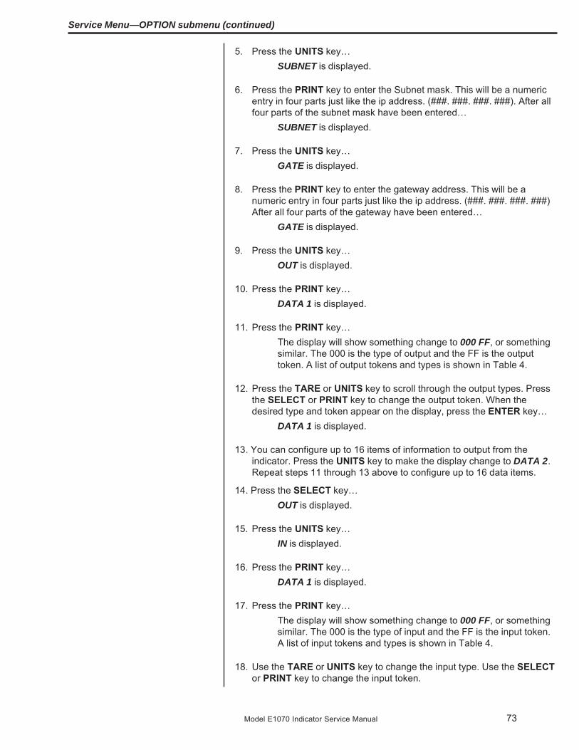
73Model E1070 Indicator Service Manual
5. Press the UNITS key…SUBNET is displayed.
6. Press the PRINT key to enter the Subnet mask. This will be a numericentry in four parts just like the ip address. (###. ###. ###. ###). After allfour parts of the subnet mask have been entered…
SUBNET is displayed.
7. Press the UNITS key…GATE is displayed.
8. Press the PRINT key to enter the gateway address. This will be anumeric entry in four parts just like the ip address. (###. ###. ###. ###)After all four parts of the gateway have been entered…
GATE is displayed.
9. Press the UNITS key…OUT is displayed.
10. Press the PRINT key…DATA 1 is displayed.
11. Press the PRINT key…The display will show something change to 000 FF, or somethingsimilar. The 000 is the type of output and the FF is the outputtoken. A list of output tokens and types is shown in Table 4.
12. Press the TARE or UNITS key to scroll through the output types. Pressthe SELECT or PRINT key to change the output token. When thedesired type and token appear on the display, press the ENTER key…
DATA 1 is displayed.
13. You can configure up to 16 items of information to output from theindicator. Press the UNITS key to make the display change to DATA 2.Repeat steps 11 through 13 above to configure up to 16 data items.
14. Press the SELECT key…OUT is displayed.
15. Press the UNITS key…IN is displayed.
16. Press the PRINT key…DATA 1 is displayed.
17. Press the PRINT key…The display will show something change to 000 FF, or somethingsimilar. The 000 is the type of input and the FF is the input token.A list of input tokens and types is shown in Table 4.
18. Use the TARE or UNITS key to change the input type. Use the SELECTor PRINT key to change the input token.
Service Menu—OPTION submenu (continued)

74 Model E1070 Indicator Service Manual
19. When the desired type and token appear on the display, press theENTER key…
DATA 1 is displayed.
20. You can configure up to 16 items of information to input into the indica-tor. Press the UNITS key to make the display change to DATA 2.Repeat steps 16 through 19 above to configure up to 16 data items.
21. Press the SELECT key…IN is displayed.
22. Press the UNITS key…TRADE is displayed.
23. Press the PRINT key to configure word swapping.Word swapping only affects the output and/or input data if long,unsigned long, or floating point data types are used. These threedata types are each made up of 4 bytes or 2 16-bit words. Wordswapping will change the order that the 16-bit words are output/input. The display will show either “on” or “off”.
24. Press the TARE or UNITS key to toggle between ON and OFF. Whenthe desired selection appears on the display, press either the ENTER orPRINT key…
TRADE is displayed.
25. Press the UNITS key…ENDIAN is displayed.
26. Press the PRINT key…LITTLE or BIG is displayed.
27. Press the TARE or UNITS key to toggle between LITTLE and BIG.When the desired selection appears on the display, press the ENTER orPRINT key…
ENDIAN is displayed.
28. This completes the Modbus/TCP configuration. Press the ESC key toexit the service menu.
1. If E-net3 (Ethernet IP) was chosen at the beginning of the NETS setup. .IP is displayed.
2.. Press the PRINT key to configure the IP address of the indicator…The first octet of the IP address is shown.
(NETS) ETHERNET 3Ethernet IP
(Raw sockets)
Service Menu—OPTION submenu (continued)
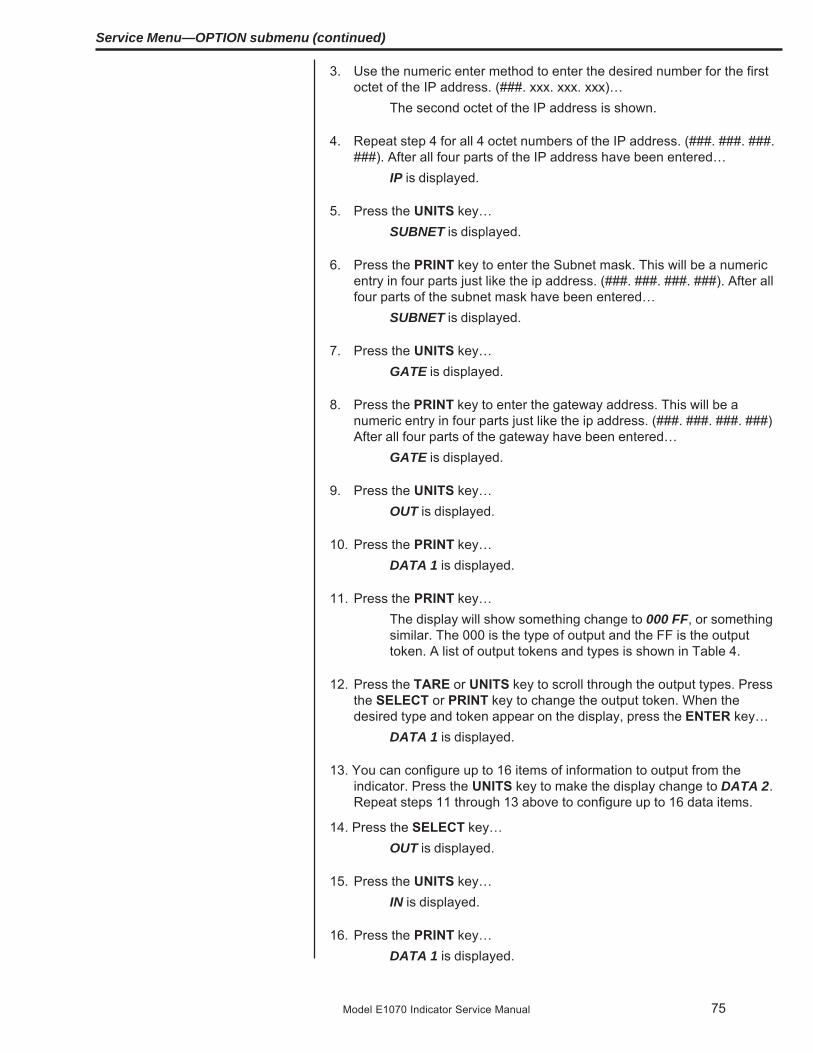
75Model E1070 Indicator Service Manual
3. Use the numeric enter method to enter the desired number for the firstoctet of the IP address. (###. xxx. xxx. xxx)…
The second octet of the IP address is shown.
4. Repeat step 4 for all 4 octet numbers of the IP address. (###. ###. ###.###). After all four parts of the IP address have been entered…
IP is displayed.
5. Press the UNITS key…SUBNET is displayed.
6. Press the PRINT key to enter the Subnet mask. This will be a numericentry in four parts just like the ip address. (###. ###. ###. ###). After allfour parts of the subnet mask have been entered…
SUBNET is displayed.
7. Press the UNITS key…GATE is displayed.
8. Press the PRINT key to enter the gateway address. This will be anumeric entry in four parts just like the ip address. (###. ###. ###. ###)After all four parts of the gateway have been entered…
GATE is displayed.
9. Press the UNITS key…OUT is displayed.
10. Press the PRINT key…DATA 1 is displayed.
11. Press the PRINT key…The display will show something change to 000 FF, or somethingsimilar. The 000 is the type of output and the FF is the outputtoken. A list of output tokens and types is shown in Table 4.
12. Press the TARE or UNITS key to scroll through the output types. Pressthe SELECT or PRINT key to change the output token. When thedesired type and token appear on the display, press the ENTER key…
DATA 1 is displayed.
13. You can configure up to 16 items of information to output from theindicator. Press the UNITS key to make the display change to DATA 2.Repeat steps 11 through 13 above to configure up to 16 data items.
14. Press the SELECT key…OUT is displayed.
15. Press the UNITS key…IN is displayed.
16. Press the PRINT key…DATA 1 is displayed.
Service Menu—OPTION submenu (continued)

76 Model E1070 Indicator Service Manual
17. Press the PRINT key…The display will show something change to 000 FF, or somethingsimilar. The 000 is the type of input and the FF is the input token.A list of input tokens and types is shown in Table 4.
18. Use the TARE or UNITS key to change the input type. Use the SELECTor PRINT key to change the input token.
19. When the desired type and token appear on the display, press theENTER key…
DATA 1 is displayed.
20. You can configure up to 16 items of information to input into the indica-tor. Press the UNITS key to make the display change to DATA 2.Repeat steps 17 through 20 above to configure up to 16 data items.
21. Press the SELECT key…IN is displayed.
22. Press the UNITS key…TRADE is displayed.
23. Press the PRINT key to configure word swapping.Word swapping only affects the output and/or input data if long,unsigned long, or floating point data types are used. These threedata types are each made up of 4 bytes or 2 16-bit words. Wordswapping will change the order that the 16-bit words are output/input. The display will show either “on” or “off”.
24. Press the TARE or UNITS key to toggle between ON and OFF. Whenthe desired selection appears on the display, press either the ENTER orPRINT key…
TRADE is displayed.
25. Press the UNITS key…ENDIAN is displayed.
26. Press the PRINT key…LITTLE or BIG is displayed.
27. Press the TARE or UNITS key to toggle between LITTLE and BIG.When the desired selection appears on the display, press the ENTER orPRINT key…
ENDIAN is displayed.
28. This completes the Ethernet IP configuration. Press the ESC key to exitthe service menu.
Service Menu—OPTION submenu (continued)

77Model E1070 Indicator Service Manual
(NETS) Remote I/O
Service Menu—OPTION submenu (continued)
1. If rio (Remote I/O) was selected in step 5 above…Baud appears on the display.
2. Press the PRINT key.The current baud rate is displayed. This may be “57.6” (57.6k),“115.2” (115.2k), or “230.4” (230.4k).
3. Scroll through the choices by pressing the TARE or UNITS key. Pressthe PRINT key when the value you want is displayed.
BAUD is displayed.
4. Press the UNITS keyRADDR is displayed.
5. Press the PRINT key to configure the rack address…The current rack address is displayed.
6. Key in the desired rack address. This value may be between 0 and 59.Press the F1 key when the correct rack address has been entered.
RADDR is displayed.
7. Press the UNITS keyRSIZE is displayed.
8. Press the PRINT key to configure the rack size.The current rack size is displayed. This may be “1/4”,”1/2”, “3/4”,or “full”.
9. Scroll through the choices by pressing the TARE or UNITS key. Pressthe PRINT key when the value you want is displayed.
RSIZE is displayed.
10. Press the UNITS keyRQUATR is displayed.
11. Press the PRINT key to configure the starting quarter.The current setting for starting quarter is displayed. This may be“1st”,”2nd”, “3rd”, or “4th”.
12. Scroll through the choices by pressing the TARE or UNITS key. Pressthe PRINT key when the value you want is displayed.
RQUATR is displayed.
13. Press the UNITS keyLRACK is displayed.
14. Press the PRINT key to configure the last rack setting.The current setting for last rack is displayed. This will be “yes” or“no”.

78 Model E1070 Indicator Service Manual
Service Menu—OPTION submenu (continued)
15. Toggle between “yes” and “no” with the TARE or UNITS key. Press thePRINT key when the value you want is displayed.
LRACK is displayed.
16. Press the UNITS keyIOTYPE is displayed.
17. Press the PRINT key to configure the IO Type.The current setting for IO Type is displayed. This will be cyclic orblock.
18. Toggle between the choices with the TARE or UNITS key. Press thePRINT key when the value you want is displayed.
IOTYPE is displayed.
19. Press the UNITS key…OUT is displayed.
20. Press the PRINT key…DATA 1 is displayed.
21. Press the PRINT key.The display will show something change to “000 FF”, or somethingsimilar. The 000 is the type of output and the FF is the outputtoken. A list of output tokens and types is shown in Table 4.
22. Use the TARE or UNITS key to change the output type. Use the SE-LECT or PRINT key to change the output token. When the desired typeand token appear on the display, press the F1 key.
DATA 1 is displayed.
23. You can configure up to 16 items of information to output from theindicator. Press the UNITS key.
Display changes to DATA 2.
24. Repeat steps 21 and 22 above to configure up to 16 data items.25. Press the SELECT key…
OUT is displayed.
26. Press the UNITS key…IN is displayed.
27. Press the PRINT key.DATA 1 is displayed.
28. Press the PRINT key.The display will show something change to “000 FF”, or somethingsimilar. The 000 is the type of input and the FF is the input token.A list of input tokens and types is shown in Table 4.

79Model E1070 Indicator Service Manual
29. Use the TARE or UNITS key to change the input type. Use the SELECTor PRINT key to change the input token. When the desired type andtoken appear on the display, press the F1 key…
DATA 1 is displayed.
30. You can configure up to 16 items of information to input into the indica-tor. Press the UNITS key.
DATA 2 is displayed.
31. Repeat steps 28 and 29 above to configure up to 16 data items.32. Press the SELECT key.
IN is displayed.
33. Press the UNITS key.TRADE is displayed.
34. Press the PRINT key to configure word swapping. Word swapping onlyaffects the output and/or input data if a long, unsigned long, or floatingpoint data type is used. These three data types are each made up of 4bytes or 2 16-bit words. Word swapping will change the order that the16-bit words are output/input.
The display will show either ON or OFF.
35. Use the TARE or UNITS key to toggle between the choices. When thedesired selection appears on the display, press either the F1 or PRINTkey.
TRADE is displayed.
36. Press the UNITS key.ENDIAN is displayed.
37. Press the PRINT key.The current setting is displayed. Choices are LITTLE or BIG.
38. Use the TARE or UNITS key to toggle between the choices. When thedesired selection appears on the display, press either the F1 or PRINTkey.
ENDIAN is displayed.
39. This completes the Remote IO configuration. Press SELECT to moveup the menu structure or press the ZERO key to exit the service menu.
Service Menu—OPTION submenu (continued)

80 Model E1070 Indicator Service Manual
(NETS) ETHERNET 4TCP/ IP Server
1. If you selected E-NET4 (ETHERNET 4 TCP/IP Server) at the beginningof the NETS setup. .
IP is displayed.
2. Press the PRINT key to configure the IP address of the indicator…The first octet of the IP address is shown.
3. Key in the desired number for the first octet of the IP address. (###.xxx.xxx. xxx)…
The second octet of the IP address is shown.
4. Repeat step 3 above for all 4-octet numbers of the IP address. (###.###. ###. ###). After all four parts of the IP address have been entered.
IP is displayed.
5. Press the UNITS key…SUBNET is displayed.
6. Press the PRINT key to enter the Subnet mask. This will be a numericentry in four parts just like the IP address. (###. ###. ###. ###)
7. After all four parts of the subnet mask have been entered…SUBNET is displayed.
8. Press the UNITS key…GATE is displayed.
9. Press the PRINT key to enter the gateway address. This will be anumeric entry in four parts just like the IP address. (###. ###. ###. ###)
10. After all four parts of the gateway have been entered…GATE is displayed.
11. Press the UNITS key…SMTP is displayed.
12. If you are connecting to a mail server and you plan to send e-mails fromthe indicator, press the PRINT key to enter the IP address of the (host)mail server. This will be a numeric entry in four parts (###. ###. ###.###) just like the IP address. The E-tools PC application must be usedto enter the indicator’s user name, domain name, recipient address, andsender address.
13. After all four parts of the SMTP Address have been entered…SMTP is displayed.
14. Press the UNITS key…PORT is displayed.
15. Press the PRINT key to enter the port number of the indicator. This is anumeric entry (####). After the Port number has been entered…
PORT is displayed.
Service Menu—OPTION submenu (continued)

81Model E1070 Indicator Service Manual
16. Press the UNITS key…EMAIL is displayed.
17. If you want the indicator to automatically send an email when an erroroccurs, press the PRINT key to configure this…
ERR.LOG is displayed.
18. Press the PRINT key…ON or OFF is displayed.
19. Use the UNITS or TARE key to toggle between ON and OFF. To sendan email when an overload or underload occurs on the scale, select ON.Otherwise select OFF. Press either the PRINT or ENTER key to acceptyour selection…
ERR.LOG is displayed.
20. Press the UNITS key…S-COM is displayed.
21. Press the PRINT key…ON or OFF is displayed.
22. Press UNITS or TARE to toggle between ON and OFF. If the indicator isbeing connected to a SensorComm junction box and you want to sendan email when a SensorComm error occurs, select ON. Otherwiseselect OFF. Press either the PRINT or ENTER key to accept yourselection…
S-COM is displayed.
23. Press the UNITS key…GHOST is displayed.
24. Press the PRINT key…ON or OFF is displayed.
25. If the indicator is being connected to a SensorComm junction box andGhosting is enabled and you want to send and email when a cell isghosted, select ON. Otherwise select OFF. Toggle to your choice andpress either the PRINT or ENTER key to accept your selection…
GHOST is displayed.
26. Press the SELECT key, then the UNITS key….ProtcL is displayed.
27. Press the PRINT key…SMA or Enq is displayed.
Service Menu—OPTION submenu (continued)

82 Model E1070 Indicator Service Manual
28. Toggle between the two choices using the TARE and UNITS keys.When the desired choice is shown, press the PRINT key to select it.
SMA – the SMA protocol over the Ethernet connection. This is theexact same protocol used on the serial ports. See the Service-Serial section of this manual for details.
Enq – If Enq is chosen you will be prompted to key in a polling charac-ter. This can be any value from 0 to 255. Example: if the desiredpolling character is a carriage return, enter 13 for the pollingcharacter. After the polling character is keyed in, press theENTER key and the display will return to protcL. When thepolling character is received on the Ethernet connection, theindicator will act as if the PRINT key has been pressed (all ofthe formats-to-print will be sent out of the configured port). If youwant the print format(s) to be sent back on the Ethernet connec-tion, the print formats must be configured for tcpip1 (net1) ortcpip2 (net2). See the Service-App and Service-Serial sectionsof this manual for details on setting up the print formats.
29. This completes the Ethernet TCP/IP Server configuration. Press theESC key to exit the service menu.
Service Menu—OPTION submenu (continued)

83Model E1070 Indicator Service Manual
Token Inbound Outbound Inbound Outbound Token Tokento net1 from net 1 to net 2 from net 2 (dec.) (hex)
Gross X X 0 00Net X X 1 01Tare X X X X 2 02Peak X X 3 03Count X X 4 04PLU Piece weight X X X X 5 05PLU number X X X X 6 06PLU Gross Accumulator X X 7 07PLU Net Accumulator X X 8 08PLU Total counter X X 9 09PLU Count Accumulator X X 10 0APLU Tare value X X X X 11 0BPLU ID X X X X 12 0CPLU Lower Target weight X X X X 13 0DPLU Upper Target weight X X X X 14 0ERecipe Ingredient number X X 15 0FRecipe Ingredient target weight X X 16 10Recipe Ingredient actual weightwhen target is met X X 17 11Motion/Weigher Steady X X 18 12Center of Zero/zero balance X X 19 13Overload X X 20 14Underload X X 21 15Input1-3 X X X X 22 16Output 1-3 X X X X 23 17Serial number X X 24 18Watchdog counter X X 25 19Remote zero X X 26 1ARemote tare X X 27 1BRemote print X X 28 1CRemote accumulate X X 29 1DBridge1 X** X* X* X** 30 1EBridge2 X** X* X* X** 31 1FBridge3 X** X* X* X** 32 20Bridge4 X** X* X* X** 33 21Bridge5 X** X* X* X** 34 22Bridge6 X** X* X* X** 35 23Bridge7 X** X* X* X** 36 24Bridge8 X** X* X* X** 37 25Bridge9 X** X* X* X** 38 26Bridge10 X** X* X* X** 39 27Bridge11 X** X* X* X** 40 28Bridge12 X** X* X* X** 41 29Bridge13 X** X* X* X** 42 2ABridge14 X** X* X* X** 43 2BBridge15 X** X* X* X** 44 2CBridge16 X** X* X* X** 45 2DIndicator Healthy X X 46 2E
Service Menu—OPTION submenu (continued)
Table 4Tokens
* Bridge tokens that are inbound to net2 can be outputs for net1** Bridge tokens that are inbound to net1 can be outputs for net2

84 Model E1070 Indicator Service Manual
When mapping signed characters, unsigned characters, signed integers,unsigned integers, signed longs, and unsigned longs, an outbound valuemay be scaled up/down depending on the division size of the scale.
Outbound ValuesThe following tokens may be affected by division size:
- Gross (token 0)- Net (token 1)- Tare (token 2)- Peak (token 3)- PLU Piece Weight (token 5)- PLU Gross Accumulator (token 7)- PLU Net Accumulator (token 8)- PLU Tare Value (token 11)- PLU Lower Target Weight (token 13)- PLU Upper Target Weight (token 14)- Recipe Ingredient Target Weight (token 16)- Recipe Ingredient Actual Weight (token 17)
If the division size of the scale is less than 1, the value that is mapped will bescaled up by 10X. Where X equals the number of digits to the right of thedecimal point. Any floating-point values will not be scaled up.
Example:Token = 0 (Gross)Type = 4 (Signed Long)Division Size = 0.01
There are two digits to the right of the decimal point so the gross weightbeing set out of the network connection will be multiplied by 102 (100). If thegross weight on the display is 110.54, you should see a value of 11054 onthe network connection.
Inbound ValuesThe following tokens may be affected by division size:
- Tare (token 2)- PLU Piece Weight (token 5)- PLU Tare Value (token 11)- PLU Lower Target Weight (token 13)- PLU Upper Target Weight (token 14)
TYPE # Data Type # of Bytes Range of Value
0 Signed Character 1 -127 to 1271 Unsigned Character 1 0 to 2552 Signed Integer 2 -32767 to 327673 Unsigned Integer 2 0 to 655354 Signed Long 4 -2,147,483,647 to 2,147,483,6475 Unsigned Long 4 0 to 4,294,967,2956 Float 4 1.0E-37 to 1.0E37
Network Scaling
Service Menu—OPTION submenu (continued)

85Model E1070 Indicator Service Manual
If the division size of the scale is less than 1, the value that is mapped will bescaled down by 10X. Where X equals the number of digits to the right of thedecimal point. Any floating-point values will not be scaled down.
Example:Token = 2 (Tare)Type = 4 (Signed Long)Division Size = 0.01
There are two digits to the right of the decimal point so the tare weightcoming into the indicator will be divided by 102 (100). If the desired tareweight is 99.56, a value of 9956 must be sent.
Follow these steps to configure the Network/Sensorcomm status annuncia-tor.
1. With Error displayed, press the PRINT key…The current setting will be displayed. This may be Off, S-comm,net1, or net2.
2. Use the UNITS and TARE keys to change the setting, and press theENTER key to accept the desired setting once it is displayed.
Off The annunciator will always remain off.
S-comm The annunciator will show the status of the Sensorcomm scale.
Red – a cell has been ghosted. Check the ghost log.
Green – a sensorcomm error has occurred. Check the errorlog.
Off – Scale is functioning normally.
Net1 The annunciator will show the status of network #1.
Net2 The annunciator will show the status of network #2.
Red – A network error has occurred. Check the networksettings on the indicator and PLC, and reboot theindicator.
Green – The network connection has been established.
Amber – The network is ready for a connection, but no connec-tion has been established.
This completes the Service menu. Press the ESC key to return to normalweighing mode. You will be prompted to save the changes you’ve made.Press the ESC key to abort any changes made and return to normal operat-ing mode or press ENTER to accept them and return to normal operatingmode. BUSY flashes on the display while the unit saves data.
Error(Error Annunciator)

86 Model E1070 Indicator Service Manual
Supervisor Menu The Supervisor menu is shown in Figure 14. Use this menu to set time anddate, clear and print reports, perform diagnostic tests and view auditcounters.Password for the Supervisor
menu is 1793.
Figure 14Supervisor menu flowchart
WARNING: Entering this menu and changing settingsmay affect operation of the indicator and may require aservice call to correct. Be sure you want to changesettings before doing so.
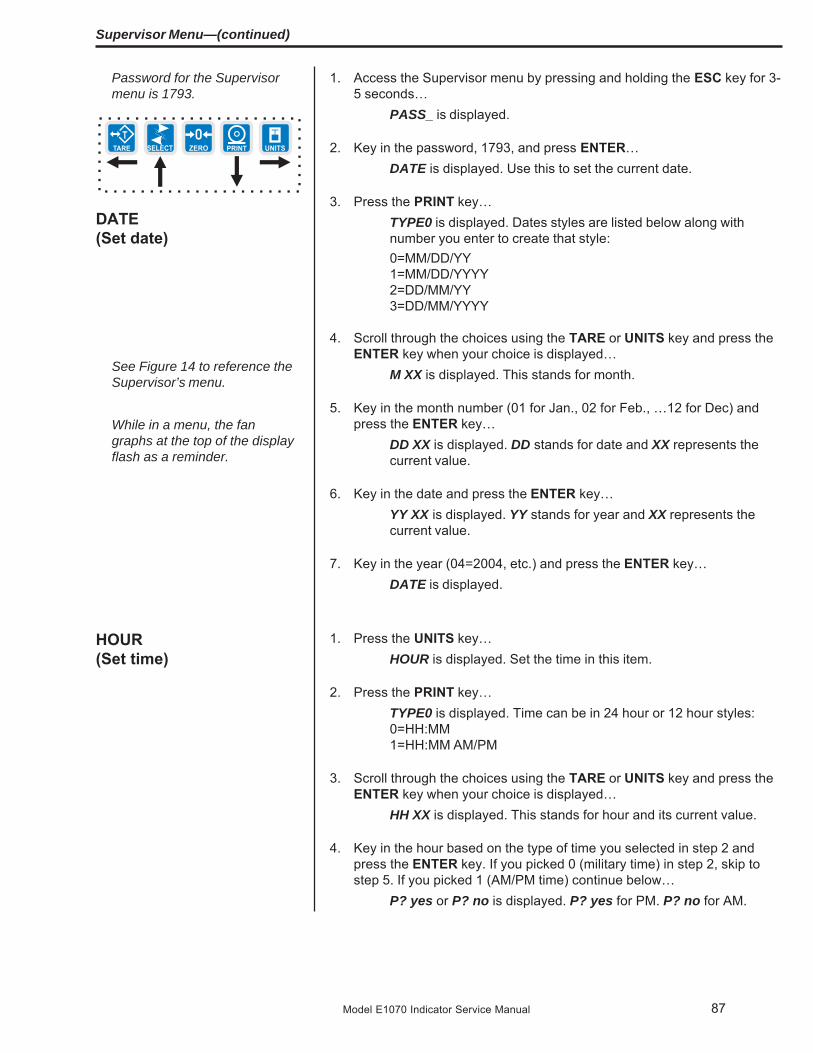
87Model E1070 Indicator Service Manual
DATE(Set date)
1. Access the Supervisor menu by pressing and holding the ESC key for 3-5 seconds…
PASS_ is displayed.
2. Key in the password, 1793, and press ENTER…DATE is displayed. Use this to set the current date.
3. Press the PRINT key…TYPE0 is displayed. Dates styles are listed below along withnumber you enter to create that style:0=MM/DD/YY1=MM/DD/YYYY2=DD/MM/YY3=DD/MM/YYYY
4. Scroll through the choices using the TARE or UNITS key and press theENTER key when your choice is displayed…
M XX is displayed. This stands for month.
5. Key in the month number (01 for Jan., 02 for Feb., …12 for Dec) andpress the ENTER key…
DD XX is displayed. DD stands for date and XX represents thecurrent value.
6. Key in the date and press the ENTER key…YY XX is displayed. YY stands for year and XX represents thecurrent value.
7. Key in the year (04=2004, etc.) and press the ENTER key…DATE is displayed.
1. Press the UNITS key…HOUR is displayed. Set the time in this item.
2. Press the PRINT key…TYPE0 is displayed. Time can be in 24 hour or 12 hour styles:0=HH:MM1=HH:MM AM/PM
3. Scroll through the choices using the TARE or UNITS key and press theENTER key when your choice is displayed…
HH XX is displayed. This stands for hour and its current value.
4. Key in the hour based on the type of time you selected in step 2 andpress the ENTER key. If you picked 0 (military time) in step 2, skip tostep 5. If you picked 1 (AM/PM time) continue below…
P? yes or P? no is displayed. P? yes for PM. P? no for AM.
Password for the Supervisormenu is 1793.
See Figure 14 to reference theSupervisor’s menu.
Supervisor Menu—(continued)
While in a menu, the fangraphs at the top of the displayflash as a reminder.
HOUR(Set time)

88 Model E1070 Indicator Service Manual
The PLU report contains thefollowing information for eachof the 11 channels:
Channel #ID #Gross Accum.Net Accum.Count Accum.TotalTare ValueLower LimitUpper LimitPiece WeightCutoff Wt1Cutoff Wt2Cutoff Wt3
Supervisor Menu—(continued)
SETUP(Setup menu)
APP(Application submenu)
PLU(Product Look Up)
5. Toggle between the choices using the TARE or UNITS key and pressthe ENTER key when your choice is displayed…
M XX is displayed. M stands for minute and XX represents thecurrent value.
6. Key in the minute and press the ENTER key…HOUR is displayed.
1. Press the UNITS key…SETUP is displayed. Use this submenu to print and/or clearapplication reports, choose operation modes or values for applica-tions which have choices and view various function logs. Each isexplained in the following steps.
2. Press the PRINT key…APP is displayed. As stated in the Service menu section of themanual, applications are enabled in the Service menu but you doeach application’s setup in this area of the Supervisor menu.
3. Press the PRINT key…PLU is displayed. This stands for Product Look Up. There are 11PLU memory channels, numbered 0-10. Each channel contains allthe parameter values and accumulator totals associated with allthe different applications. This menu item lets you print out all theinformation in each channel, in all the applications, and/or clearthe information.
4. Press the PRINT key…PRINT is displayed. Use this item to print out a complete report ofall application parameters and totals.
5. Press the PRINT key …PORT 1 or PORT 2 is displayed. Use this item to select which portto use for printing the report. See note at left.
6. Toggle between PORT 1 and PORT 2 using the TARE or UNITS key.Press the ENTER key when your choice is displayed…
The report is printed and display shows BUSY briefly then returnsto PRINT.
7. Press the UNITS key…TARE is displayed. Use this item to enable multichannel presettares.
8. Press the PRINT key…ON or OFF is displayed.
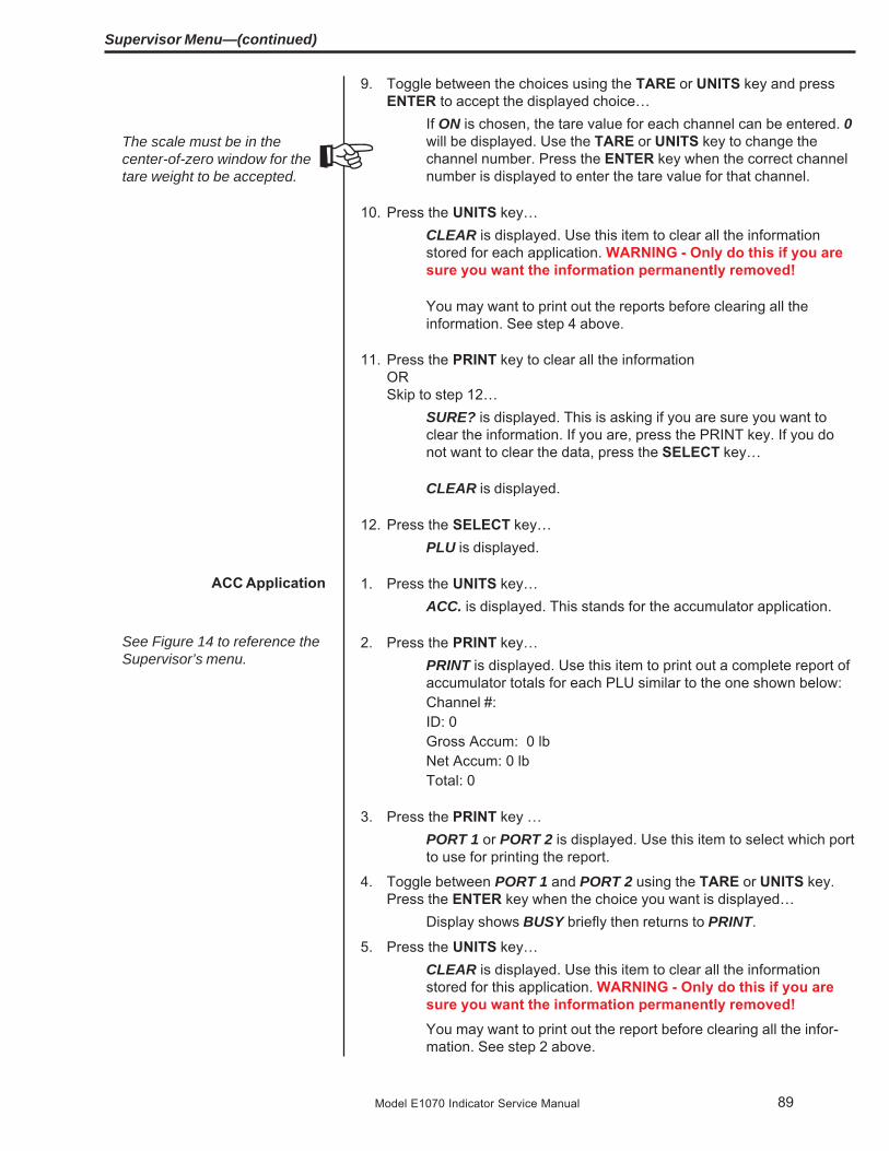
89Model E1070 Indicator Service Manual
Supervisor Menu—(continued)
The scale must be in thecenter-of-zero window for thetare weight to be accepted.
9. Toggle between the choices using the TARE or UNITS key and pressENTER to accept the displayed choice…
If ON is chosen, the tare value for each channel can be entered. 0will be displayed. Use the TARE or UNITS key to change thechannel number. Press the ENTER key when the correct channelnumber is displayed to enter the tare value for that channel.
10. Press the UNITS key…CLEAR is displayed. Use this item to clear all the informationstored for each application. WARNING - Only do this if you aresure you want the information permanently removed!
You may want to print out the reports before clearing all theinformation. See step 4 above.
11. Press the PRINT key to clear all the informationORSkip to step 12…
SURE? is displayed. This is asking if you are sure you want toclear the information. If you are, press the PRINT key. If you donot want to clear the data, press the SELECT key…
CLEAR is displayed.
12. Press the SELECT key…PLU is displayed.
1. Press the UNITS key…ACC. is displayed. This stands for the accumulator application.
2. Press the PRINT key…PRINT is displayed. Use this item to print out a complete report ofaccumulator totals for each PLU similar to the one shown below:Channel #:ID: 0Gross Accum: 0 lbNet Accum: 0 lbTotal: 0
3. Press the PRINT key …PORT 1 or PORT 2 is displayed. Use this item to select which portto use for printing the report.
4. Toggle between PORT 1 and PORT 2 using the TARE or UNITS key.Press the ENTER key when the choice you want is displayed…
Display shows BUSY briefly then returns to PRINT.
5. Press the UNITS key…CLEAR is displayed. Use this item to clear all the informationstored for this application. WARNING - Only do this if you aresure you want the information permanently removed!You may want to print out the report before clearing all the infor-mation. See step 2 above.
ACC Application
See Figure 14 to reference theSupervisor’s menu.

90 Model E1070 Indicator Service Manual
BATCH Application
Supervisor Menu—(continued)
6. Press the PRINT key to clear all the informationORSkip to step 7…
SURE? is displayed. This is asking if you are sure you want toclear the information. If you are, press the ENTER key. If you donot want to clear the data, press the SELECT key…
CLEAR is displayed.
7. Press the SELECT key…ACC. is displayed.
1. Press the UNITS key…BATCH is displayed.
2. Press the PRINT key…PRINT is displayed. Use this item to print out a complete report ofrecipe information.
3. Press the PRINT key …PORT 1 or PORT 2 is displayed. Use this item to select which portto use for printing the report.
4. Toggle between PORT 1 and PORT 2 using the TARE or UNITS key.Press the ENTER key when the choice you want is displayed…
Display shows BUSY briefly then returns to PRINT.
5. Press the UNITS key…RECIPE is displayed. Use this item to create a recipe.
6. Press the PRINT key…REC 0 is displayed.
7. Press the PRINT key to configure recipe #0 or use the TARE or UNITSkey to scroll to another recipe number. Press the PRINT key when therecipe you want is displayed…
TYPE is displayed. Set the type of recipe; Constant (CONST)Gross or Percentage (%):
CONSTANT You set the weights for each ingredient and thebatch size is always the total of these ingredientweights.
GROSS You set the gross weight at which each ingredi-ent will stop. The ingredient is complete whenthe gross weight on the scale reads the valuethat was set, regardless of the weight on thescale when the batch was started.
PERCENTAGE You set the percentage of a total batch for eachingredient and you can pick a batch size andeach ingredient amount will be calculatedautomatically.
8. Press the PRINT key…Current setting is displayed.

91Model E1070 Indicator Service Manual
Supervisor Menu—(continued)
9. Toggle between the choices by pressing the TARE or UNITS key. Pressthe PRINT key when your choice is displayed…
Your choice is selected and TYPE is displayed.
10. Press the UNITS key…PREACT is displayed. A preact is the time it takes an ingredient(which is falling from an auger or other feeder) to reach the scaleafter the auger or feeder is shut off. There will always be materialin “free-fall” after an ingredient is shut off and the indicator willautomatically calculate this and update this value.
The first time a batch is run, overage for any ingredient weight iscalculated and the next time the ingredient is being weighed theoutput will be shut down so approximately 70% of the overage isreduced. This occurs each time a batch is run so that the systemquickly learns and produces accurate batches.
Under this item you can turn the preact on or off, or clear a currentpreact.
11. Press the PRINT key to set the preact…ON or OFF is displayed.
12. Scroll through the choices (ON, OFF, CLEAR) with the TARE or UNITSkey. Press ENTER when your choice is displayed…
PREACT is displayed.
13. Press the UNITS key…INGR X is displayed. X is the ingredient number. You have up to 8ingredients for which you can set the following:BASIS Set whether the ingredient is based on weight (Scale),
time (Time) or pulse counts (Cntr).SETPT Set the output you want associated with the ingredient.
Choices are 1, 2 , 3 or None. Outputs must be enabledin a password protected menu. Contact your localAvery Weigh-Tronix supplier or distributor for assis-tance.
DELAY Set a time delay between when a basis is met and thenext ingredient action is started.
14. Press the PRINT key…BASIS is displayed.
15. Press the PRINT key…The current setting is displayed; SCALE, TIME, or CNTR.
16. Scroll through the choices with the TARE or UNITS key. Press ENTERwhen your choice is displayed…
If you choose SCALE you are prompted to enter an ingredientweight. If you choose TIME, your are prompted to enter a timevalue. If you choose CNTR, your are prompted to enter thenumber of pulses.
17. Key in values and press the ENTER key…BASIS is displayed.
See Figure 14 to reference theSupervisor’s menu.
If SCALE is chosen for thebasis, you can enter a negativeweight to do an “unload.” Theselected output will activateuntil the entered amount ofweight is removed from thescale.

92 Model E1070 Indicator Service Manual
See Figure 14 to reference theSupervisor’s menu.
Supervisor Menu—(continued)
18. Press the UNITS key…SETPT is displayed.
19. Press the PRINT key…1 is displayed. This stands for Setpoint 1.
20. Scroll through the choices with the TARE or UNITS key. Press ENTERwhen your choice is displayed…
SETPT is displayed.
If you chose 1 this ingredient will use output #1. The same is truefor the 2 and 3 choices. If you choose NONE, no output will beactivated when the ingredient is called by the recipe.
21. Press the UNITS key…DELAY is displayed.
22. Press the PRINT key…The current delay value in seconds is displayed.
23. Accept this value by pressing ENTER or key in a new value and pressENTER…
DELAY is displayed. Repeat steps 13 through 23 for all theingredients in your recipe.
24. Press the SELECT key twice…RECIPE is displayed.
25. Press the UNITS key…MODE is displayed. Use this item to set the mode of the batchingapplication to Automatic, Manual, Fill or Continuous batching.
AUTO In auto mode, after the user begins the batching processthe indicator will activate the OP2 output when the weightfor OP1 has been reached. When the weight for OP2 isreached, OP3 will activate. This happens with no interven-tion from the operator.
MAN. In manual mode, after the user begins the batchingprocess, the user must press the F1 key to activate eachsubsequent output after each output weight is reached.
FILL In FILL mode, any recipe that has been setup is ignored.The filling process is run based on the values set for theoutputs. In order to complete the filling process, at leastone output must be enabled.
CONT Continuous batching mode. This mode is very close to theAuto mode, but in continuous mode, another batch isstarted immediately after the previous batch has finished.In Auto mode, the user must press the F1 key to starteach batch.
26. Press the PRINT key…The current mode setting is displayed.

93Model E1070 Indicator Service Manual
Supervisor Menu—(continued)
27. Toggle between the choices by pressing the TARE or UNITS key. Pressthe ENTER key when your choice is displayed…
MODE is displayed.
28. Press the UNITS key…CLEAR is displayed. Use this item to clear all the informationstored for this application. WARNING - Only do this if you aresure you want the information permanently removed!
You may want to print out the report before clearing all the infor-mation. See step 2 in this section.
29. Press the PRINT key to clear all the informationORSkip to step 30…
SURE? is displayed. This is asking if you are sure you want toclear the information. If you are, press the ENTER key. If you donot want to clear the data, press the SELECT key…
CLEAR is displayed.
30. Press the UNITS key…PRINT is displayed.
31. Press the PRINT key…PORT 1 is displayed.
32. Toggle between PORT 1 and PORT 2 using the TARE or UNITS key.Press the ENTER key when your choice is displayed…
The recipes and batch report will be printed.
33. Press the SELECT key…BATCH is displayed.
1. Press the UNITS key…TARGET is displayed. Use this item to print and clear reports forthe checkweigher application and to set the type of sampling to beused, Limit or Sample.
2. Press the PRINT key…PRINT is displayed. Use this item to print out a complete report ofcheckweigher information.
3. Press the PRINT key …PORT 1 or PORT 2 is displayed. Use this item to select which portto use for printing the report.
4. Toggle between PORT 1 and PORT 2 using the TARE or UNITS key.Press the ENTER key when the choice you want is displayed…
Display shows BUSY briefly then returns to PRINT.
TARGET application(Checkweighing)

94 Model E1070 Indicator Service Manual
Supervisor Menu—(continued)
You do not set the limits in thismenu item. Limits are set innormal operation mode. Thismenu item, TYPE, allows youto set the mode of choosingthe target weight and limits.
If target trips are used, theGross Zero Band in theService>Scale menu must beconfigured to something otherthan 0. The OP1, OP2, or OP3output will not turn off until thescale returns to the gross zeroband.
To use Sample mode, bothmulti-interval and preset taresshould be disabled. To disablemulti-interval, set the scalesdivision size to a whole number(not 1/2, 2/5, 5/10, 10/20 or 20/50). Preset tares are disabledin the Supervisor>Setup>App>PLU menu.
5. Press the UNITS key…TYPE is displayed. Use this to choose the mode of setting thetarget weight for the checkweighing application. You have twochoices; LIMIT and SPL (sample). See note at left.
LIMIT In this mode you enter the upper and lower limits for youritem and the indicator will use those values to run thedisplay.
SPL In this mode you use a correct weight “product” on thescale to set the target weight. The indicator will use thisweight to run the display. After SPL is chosen, a number isdisplayed. This is the sample tolerance. When a sample isdone, the upper and lower limits will automatically be±(sample tolerance) divisions from the target weight.
6. Toggle between the choices by pressing the TARE or UNITS key. Pressthe ENTER key when your choice is displayed…
TYPE is displayed.
7. Press the UNITS key…TRIPS is displayed. Use this to set outputs to follow over/under/accept or to function as standard outputs.
8. Toggle between TARGET and STNDRD by using the TARE or UNITSkey:
TARGET OP1 is UnderOP2 is AcceptOP3 is Over
STANDARD You can configure outputs from weigh mode.Generally Accept/Reject.
9. Press ENTER to accept the displayed choice…TRIPS is displayed.
10. Press the UNITS key…DIV is displayed.
11. To configure how many divisions will be equal to one graduation on thefan graph, press the PRINT key…
A number is displayed.
12. Press ENTER to accept the displayed number of divisions or enter anew number and press ENTER…
DIV is displayed.
13. Press the UNITS key…CLEAR is displayed. Use this item to clear all the informationstored for this application. WARNING - Only do this if you aresure you want the information permanently removed!
You may want to print out the report before clearing all the infor-mation. See step 2 in this section.

95Model E1070 Indicator Service Manual
Supervisor Menu—(continued)
14. Press the PRINT key to clear all the informationORSkip to step 15…
SURE? is displayed. This is asking if you are sure you want toclear the information. If you are, press the ENTER key. If you donot want to clear the data, press the SELECT key…
CLEAR is displayed.
15. Press the SELECT key…TARGET is displayed.
1. Press the UNITS key…COUNT is displayed. Use this item to clear and print reports forthe count application.
2. Press the PRINT key…PRINT is displayed. Use this item to print out a complete report ofcount application information.
3. Press the PRINT key …PORT 1 or PORT 2 is displayed. Use this item to select which portto use for printing the report.
4. Toggle between PORT 1 and PORT 2 using the TARE or UNITS key.Press the ENTER key when the choice you want is displayed…
Display shows BUSY briefly then returns to PRINT.
5. Press the UNITS key…MIN is displayed. Use this item to set the minimum sample weightas a percent of capacity.
6. Press the PRINT key…Current value is displayed.
7. Key in a percentage from 0-100% and press ENTER…MIN is displayed.
8. Press the UNITS key…SIZE is displayed. This is the sample size parameter. Use this toset the sample size for the counting application.
9. Press the PRINT key…Current sample size is displayed.
10. Key in a new sample size. Press ENTER to accept…SIZE is displayed.
Count Application
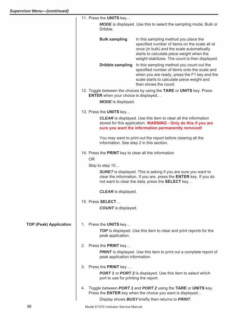
96 Model E1070 Indicator Service Manual
Supervisor Menu—(continued)
11. Press the UNITS key…MODE is displayed. Use this to select the sampling mode; Bulk orDribble.
Bulk sampling In this sampling method you place thespecified number of items on the scale all atonce (in bulk) and the scale automaticallystarts to calculate piece weight when theweight stabilizes. The count is then displayed.
Dribble sampling In this sampling method you count out thespecified number of items onto the scale andwhen you are ready, press the F1 key and thescale starts to calculate piece weight andthen shows the count.
12. Toggle between the choices by using the TARE or UNITS key. PressENTER when your choice is displayed…
MODE is displayed.
13. Press the UNITS key…CLEAR is displayed. Use this item to clear all the informationstored for this application. WARNING - Only do this if you aresure you want the information permanently removed!
You may want to print out the report before clearing all theinformation. See step 2 in this section.
14. Press the PRINT key to clear all the informationORSkip to step 15…
SURE? is displayed. This is asking if you are sure you want toclear the information. If you are, press the ENTER key. If you donot want to clear the data, press the SELECT key…
CLEAR is displayed.
15. Press SELECT…COUNT is displayed.
1. Press the UNITS key…TOP is displayed. Use this item to clear and print reports for thepeak application.
2. Press the PRINT key…PRINT is displayed. Use this item to print out a complete report ofpeak application information.
3. Press the PRINT key …PORT 1 or PORT 2 is displayed. Use this item to select whichport to use for printing the report.
4. Toggle between PORT 1 and PORT 2 using the TARE or UNITS key.Press the ENTER key when the choice you want is displayed…
Display shows BUSY briefly then returns to PRINT.
TOP (Peak) Application

97Model E1070 Indicator Service Manual
Supervisor Menu—(continued)
5. Press the UNITS key…CLEAR is displayed. Use this item to clear all the informationstored for this application. WARNING - Only do this if you aresure you want the information permanently removed!
You may want to print out the report before clearing all the infor-mation. See step 2 above.
6. Press the PRINT key to clear all the informationORSkip to step 7…
SURE? is displayed. This is asking if you are sure you want toclear the information. If you are, press the ENTER key. If you donot want to clear the data, press the SELECT key…
CLEAR is displayed.
7. Press the SELECT key…TOP is displayed.
8. Press the SELECT key…APP is displayed.
9. Press the UNITS key…LOGS is displayed. The Logs menu item allows you to view, printor clear logs for the following:CalibrationOverload and Underload ErrorsSensorComm ErrorsGhost Errors
10. Press the PRINT key…CAL is displayed. You must print out this log to view it. Below is asample of a calibration log printout:
Calibration Log:Time: 23:58
Date: 12/17/2003
Scale Serial#: 123456
Calibration Zero:
0.3456 mV/V
Calibration Span:
2.3455 mV/V @ 3000 lb
11. Press the F1 key to print the report…PORT 1 or PORT 2 is displayed. Use this to choose which port toprint through.
LOGS(Log submenu)

98 Model E1070 Indicator Service Manual
Supervisor Menu—(continued)
12. Toggle between the port choices using the TARE or UNITS key andpress ENTER when your choice is displayed…
Report is printed and display returns to CAL.
13. Press the UNITS key…ERR.LOG is displayed.
14. Press the PRINT key…OLOAD is displayed. This is the overload counter.
15. Toggle between OLOAD and ULOAD (overload) by using the TARE orUNITS key and press ENTER when your choice is displayed…
Under both OLOAD and ULOAD are choices to view the counter(CNTR) or print (PRINT) the report.
16. Toggle between CNTR and PRINT by using the TARE or UNITS keyand press ENTER when your choice is displayed…
If you choose CNTR, the overload or underload count will bedisplayed.
If you choose PRINT, you can choose the port to print through andpress ENTER. The counter value for overload or underload will beprinted.
Example:Overloads:
0 overloads
00:00 on 00-00-00
Underloads:
0 underloads
00:00 on 00-00-00
17. When you are done with the error log section, press the SELECT keyrepeatedly until…
ERR.LOG is displayed.
18. Press the UNITS key…S-COM is displayed. This is the SensorComm error log. See asample below and the note at left.
SensorComm Log:
Error #1 @ 15:00 on 12-17-03
19. Press the PRINT key…PRINT is displayed.
20. Press the PRINT key to print the report.PORT 1 or PORT 2 is displayed. Use this item to select which portto use for printing the report.
See the section SensorCommErrors to see the list of errorcodes.
The S-COM log only appears ifthe scale is configured as aSensorComm scale. TheGhost log will only appear ifghosting is enabled.

99Model E1070 Indicator Service Manual
Supervisor Menu—(continued)
21. Toggle between PORT 1 and PORT 2 using the TARE or UNITS key.Press the ENTER key when the choice you want is displayed…
Display shows BUSY briefly then returns to PRINT.
22. Press the UNITS key…CLEAR is displayed. Use this to clear the log from memory.
23. Press PRINT to clear the log…SURE? is displayed.
24. Press ENTER to clear the log…CLEAR is displayed.
25. Press the SELECT key…S-COM is displayed.
26. Press the UNITS key…GHOST is displayed. This is the Ghost error log. See a samplebelow.
Ghost Log:
Ghost is not engaged.
27. Press the PRINT key…PRINT is displayed.
28. Press the PRINT key to print the report.PORT 1 or PORT 2 is displayed. Use this item to select which portto use for printing the report.
29. Toggle between PORT 1 and PORT 2 using the TARE or UNITS key.Press the ENTER key when the choice you want is displayed…
Display shows BUSY briefly then returns to PRINT.
30. Press the UNITS key…CLEAR is displayed. Use this to clear the log from memory.
31. Press PRINT to clear the log…SURE? is displayed.
32. Press ENTER to clear the log…CLEAR is displayed.
33. Press the SELECT key…GHOST is displayed.

100 Model E1070 Indicator Service Manual
Supervisor Menu—(continued)
34. Repeatedly press the SELECT key until…SETUP is displayed.
This completes the Setup submenu of the Supervisor menu. Youcan return to normal operation (step 35) or go to the next sub-menu item, TEST, by pressing the UNITS key.
35. Press the ESC key to return to normal weighing mode. You will beprompted to save the changes you’ve made. Press the ESC key to abortany changes made or press ENTER to accept them and return tonormal operating mode.

101Model E1070 Indicator Service Manual
Supervisor Menu—(continued)
1. Proceed to the next menu by pressing the UNITS key…TEST is displayed. This menu lets you view indicator informationand test the display, keypad, serial ports, inputs and outputs.
2. Press the PRINT key…ABOUT is displayed. Press the PRINT key then repeatedly pressthe UNITS key to view the part number and revision level for thesoftware found in your indicator.
Press SELECT key to return to ABOUT.
3. Press the UNITS key…ADC is displayed. This is the mV/V output of the connectedanalog scale.
4. Press the PRINT key…The mV/V value is displayed. This value should increase asweight is applied to the scale
5. Press the SELECT key…ADC is displayed.
6. Press the UNITS key…DISP is displayed. This is the display test item.
7. Press the PRINT key to perform a dynamic test of the display.8. Press the ESC key to stop the dynamic test…
The display flashes a few more times then DISP is displayed.
9. Press the UNITS key…BUTTON is displayed. This is the button test item.
10. Press the PRINT key to perform a button test. Each key you press willbe reflected on the display screen to confirm the button is functioningcorrectly.
11. Press the ESC key to stop the button test.BUTTON is displayed.
12. Press the UNITS key…SERIAL is displayed. This is the serial test item.
13. Press the PRINT key to access the serial test.PORT 1 is displayed.
14. Jumper the transmit and receive lines on the serial port and press thePRINT key…
The display should show PASS. If there is a problem the displaywill show FAIL.
15. Press the SELECT key…PORT 1 is displayed.
TEST(Test menu)
ABOUT(Indicator information)
DISP(Display test)
BUTTON(Key test)
SERIAL(Serial port test)
ADC(Analog scale test)

102 Model E1070 Indicator Service Manual
Supervisor Menu—(continued)
16. Press the UNITS key…PORT 2 is displayed. Repeat steps 14 and 15 to test port 2.
17. Press SELECT key…SERIAL is displayed.
18. Press the UNITS key…INPUT is displayed. This is the input test item.
19. Press the PRINT key to access the test.1 2 3 is displayed. 1 stands for input 1, etc.
20. If you jumper pins 1 and 2 of the I/O connector on the bottom of theindicator…
1 becomes 0 until the jumper is removed.
To test input 2, jumper pins 1 and 3. 2 becomes 0 until the jumperis removed.
To test input 3, jumper pins 1 and 4. 3 becomes 0 until the jumperis removed.
21. Press the SELECT key…INPUT is displayed.
22. Press the UNITS key…OUTPUT is displayed. This is the output test item.
23. Press the PRINT key to access the test.OUT 1 is displayed. This stands for output 1.
24. Press the PRINT key…The display toggles between ON and OFF. This will toggle theoutput off and on. Monitor the output to see that it is turning offand on. Use a Trips Interface Unit (TIU3) or other output device.
25. Stop the test by pressing the SELECT key…OUT 1 is displayed.
26. Press the UNITS key…OUT 2 is displayed.
27. Repeat steps 23 and 25 for outputs 2 and 3…28. Press the SELECT key…
OUTPUT is displayed.
OUTPUT(Output test)
INPUT(Input test)

103Model E1070 Indicator Service Manual
Supervisor Menu—(continued)
29. Press the UNITS key…OPTION is displayed.
30. Press the PRINT key…A-OUT is displayed. This stands for the analog output test.
31. Press the PRINT key…A numeric entry screen is displayed.
32. Key in a percentage between 0 and 100 and press the ENTER key…The analog output will put out that percentage of voltage. Forexample: If you have output set from 0 to 10V and you key in apercentage of 25, the analog output voltage should read 2.5 volts.You can continue to key in other percentages, press ENTER andcheck the analog output voltage.
33. When you are finished testing the analog output, press the ESC key…A-OUT is displayed.
34. Press the UNITS key…CNTR is displayed. This checks the pulse counter.
35. Press the PRINT key to check the counter…0 is displayed if the pulse counter is inactive. If pulse input areoccurring the display will show the increasing pulse counts.
36. Press SELECT or ENTER to stop the test…CNTR is displayed.
37. Press the UNITS key…SENSOR is displayed. Use this to test the function of each weightsensor attached via SensorComm.
38. Press the PRINT key…1 is displayed.
39. Scroll through the available weight sensor numbers by pressing theTARE or UNITS key. Press the ENTER key when the sensor you wantto test is displayed…
mV/V output of the selected sensor is displayed.
40. Apply weight to the scale to verify the mV/V level changes.41. Press the ENTER key to exit the test…
Sensor number is displayed.
42. Repeat steps 38 through 40 for each sensor you want to test.43. Press the SELECT key…
SENSOR is displayed.
OPTION
A-OUT test
CNTR test
SENSOR test
This test can be used toproperly adjust the deadload ofthe scale. Each sensor shouldhave similar mV/V outputs ifthe physical load on the scaleis equally distributed.

104 Model E1070 Indicator Service Manual
Supervisor Menu—(continued)
44. Press the UNITS key…NETS is displayed.
45. Press the PRINT key…NET 1 is displayed.
46. Toggle between NET 1 or NET 2 using the TARE or UNITS key andpress PRINT when the network you want to view is displayed.
The first screen of network configuration information is displayed.
47. Repeatedly press the PRINT key to view all the configuration informa-tion. The display will return to NET 1 or NET 2 when you’ve seen all theinformation.
48. This completes the TEST submenu. Press the SELECT key until TESTis displayed.
To return to normal weighing mode, press ESC. If you press ESC you will beprompted to save any changes made. Press ESC to abort any changes orpress ENTER to save changes.
NETS test

105Model E1070 Indicator Service Manual
Supervisor Menu—(continued)
AUDIT (Audit counters)menu
CFG(Configuration audit counter)
CAL(Calibration audit counter)
The next section of the Supervisor menu is the AUDIT submenu. This menulets you view configuration and calibration audit counters. These counterscannot be changed, only viewed.
Follow these steps to access each item in the AUDIT submenu:
1. Press the UNITS key…AUDIT is displayed.
2. Press the PRINT key…CFG is displayed. This stands for the Configuration audit counter.Use this item to see how many times this indicator has beenconfigured.
3. Press the PRINT key…A number is briefly displayed, then CFG is displayed. This is thenumber of times this indicator has been configured.
4. Press the UNITS key…CAL is displayed. This stands for the Calibration audit counter.Use this item to see how many times this indicator has beencalibrated.
5. Press the PRINT key…A number is briefly displayed, then CAL is displayed. This is thenumber of times this indicator has been calibrated.
6. Press the SELECT key…AUDIT is displayed.
This completes the AUDIT submenu and the Supervisor menu. Press theSELECT key to return to normal weighing mode.

106 Model E1070 Indicator Service Manual
SensorComm Hardware Configuration and CalibrationSensorComm will only connect to communications port #1
Com Port #1 RS232, RS485 or SensorComm
GND TX / TXA RTS/TXB RX / RCA CTS/RCB +15VDCBLK RED GRN YLW BLU WHT
Main PCB jumper settings need to be set for RS485. This requires disas-sembly of the indicator and moving the jumper on JMP1 to pins 2 and 3. Seethe next section on Disassembly and Reassembly.
Wiring connections, at the indicator, are shown in the table above.
Refer to SensorComm installation manual for SensorComm box wiring.
1. Access the Service (0701) menu…CAL is displayed.
2. Press the UNITS key…SCALE is displayed.
3. Press the PRINT key…SOURCE is displayed.
4. Press the PRINT key…ANALOG or S-COM is displayed.
5. Press the UNITS key to display S-COM.6. Press the ENTER key…
SensorComm is now enabled.
7. Press the ESC key to exit and ENTER to save the configuration at theprompt.
Enable SensorComm
Only one SensorComm boxcan be connected to theindicator. The indicator can be1000 feet from the Sensor-Comm box.

107Model E1070 Indicator Service Manual
Enable/ConfigureWeigh-Bars
1. Access the Service (0701) menu…CAL is displayed.
2. Press the TARE key…OPTION is displayed.
3. Press the PRINT key…A-OUT is displayed.
4. Repeatedly press the UNITS key until SENSOR is displayed.5. Press the PRINT key…
GHOST is displayed.
6. Press the TARE keyCELLS is displayed.
7. Press PRINT…1 is displayed.
8. Press PRINT …ON or OFF is displayed.
9. Toggle between the choices by pressing the UNITS or TARE key. PressENTER to accept when ON is displayed.
10. Press UNITS to advance to the next cell.11. Repeat steps 7-10 for the correct number of cells being connected.

108 Model E1070 Indicator Service Manual
CAL submenu forSensorComm scales
Figure 15SensorComm cornering menu
1. Access the Service menu…CAL is displayed.
2. Press the PRINT key…CORNER is displayed. Use this item to corner the SensorCommsystem.
3. Press the PRINT key…DLOAD is displayed. This stands for deadload.
4. Press the PRINT key…Numeric entry screen is displayed.
5. Key in the size of your cornering (test) weight. Press the ENTER key toenter this value and to record the deadload weight…
BUSY is briefly displayed and then DLOAD is displayed.
6. Press the UNITS key…1 is displayed. This stands for sensor #1.
7. Press the PRINT key…mV/V is displayed for sensor#1.
8. Place the cornering weight over sensor #1. Wait for the scale to stabilizethen press the ENTER key…
BUSY is briefly displayed and then 1 is displayed.
If your system is set up for a SensorComm j-box, the shaded portion of thecalibration menu is the first item. See Figure 15. Follow these steps tocorner the system and then continue on with the calibration proceduresoutlined in CAL submenu for analog scales.
CORNER(SensorComm Cornering)

109Model E1070 Indicator Service Manual
9. Repeat steps 6 through 8 for each sensor…The last sensor number will be displayed.
10. Press the UNITS key…DONE is displayed.
11. Press the ENTER…BUSY is briefly displayed and then the live weight.
12. Press the ENTER key to finish the cornering process.DONE is displayed.
13. Press SELECT key…CORNER is displayed.
14. Place a weight in the center of your scale and press the UNITS key…GHOST is displayed. Use this to calculate the ghost calibrationfactors the ghost function will use in case a weight sensor fails.
15. Press the ENTER key to calculate the calibration factors…Display shows BUSY then returns to GHOST. The display willshow ABORT if the process fails. The display will show CANT ifGhost is not enabled under OPTION>SENSOR>GHOST in thisservice menu.
16. Press the UNITS key to move to the ZERO item in the Cal menu. Seethe steps for this in the earlier section, CAL submenu for analog scales.
When you are done with the SensorComm cornering and Ghost items, youneed to continue with the rest of the calibration menu. See the section afterFigure 4; ZERO (Setting Zero Reference Point).
GHOST(Ghost Calibration Factors)
All sensors (1-4) will be dis-played in Calibration. If thesensor is not enabled whenyou press the PRINT key, thedisplay will show CANT.
Downloading a configurationfile to the E1070 may corruptthe Ghost function or cause ofthe loss of Ghost calibration.

110 Model E1070 Indicator Service Manual
Error # Error Description of Error Possible Cause1 Communications error SensorComm not responding -Cable
-SensorComm hardware failure-Indicator hardware failure
2 Power fault +Vin, +EXC, or -EXC has fallen out -Power supply failureof tolerance. Voltage ±5%. -Cable
3 A to D overrange More than +5mV/V has been applied -Cable - weight sensorto the A to D converter -Weight sensor failure
-SensorComm PC board
4 A to D underrange Less than -5mV/V has been applied -Cable - weight sensorto the A to D converter -Weight sensor failure
-SensorComm PC board
5 A to D Initialization A to D converter not responding - SensorComm PC boardfailure
6 Weight sensor overrange The weight sensor output has -Abuse of scaleexceeded the configured amount. -Weight sensor failure
7 Weight sensor deadload The weight sensor output has -Gauging problem on the weightshift warning exceeded the configured amount sensor
of capacity since calibration. -Mechanical issue with the scale
8 Weight sensor deadload The output of the weight sensor has -Gauging problem on the weightshift error increased more than a configurable sensor
percent of capacity since calibration -Mechanical issue with the scale
9 Weight sensor stability The output of 1 or more weight -Mechanical issue with the scalesensor is not in the same range as -Weight sensor problemthe rest of the scale.
All messages below which mention componentsare referring to components within the SensorComm product.
SensorComm Error Messages
Table 5SensorComm errors

111Model E1070 Indicator Service Manual
Appendix A: Remote Display Functionality
This will configure the indicator to function as a remote display to anotherEvolution Series indicator. Functionality of the remote display can be config-ured through the Service menu.
The remote display is capable of displaying weight information; Gross, Tare,or Net weight, sent from the host indicator. In addition to displaying weight,the remote display can be configured to display the scale annunciators;Motion, Center of Zero, outputs, or other application specific data. Theremote display can also transmit key presses, for basic weight functions,back to the host indicator. Functions include; Print, Zero and Tare. Theremote display can be configured for these individual functions or a combi-nation of these functions.
The indicator will be configured for Remote Display mode without annuncia-tors or key functions. This will disable the keypad and annunciators of theremote indicator and display whatever valid message is received from theserial port. Mode 1 contains the string:
G<SP>00000<SP>UN<CR><LF>.
The first character can be a G or N for Gross or Net weight active value.This is followed by a space <SP> and a six digit numeric weight followed byanother space <SP>. The serial string will end with the current unit of scalemeasure <UN> and the end of message character <CR>, carriage return,followed by a line feed <LF>. Refer to Table 1 for host output protocol.
The host sends the same serial string as mode 1, but the addition of annun-ciator information will be present in the serial string from the host. Mode 2contains the string
G<SP>00000<SP>lb<CR><AN1><AN2>…<ANn><CR><LF>
Refer to figure #1 for host output protocol. The first character can be a G orN for Gross or Net weight active value. This is followed by a space <SP>and a six digit numeric weight followed by another space <SP>. The serialstring will end with the current unit of scale measure <UN> and the end ofmessage character <CR>, carriage return. Annunciators are mappedaccording to the bit table, Table 2, and transmitted from the host indicator tothe remote display after the end of message character.
The indicator will be configured for Remote Display mode without annuncia-tors. This will enable the remote display keypad and display whatever validmessage is received from the serial port. Mode 3 contains the string:
G<SP>00000<SP>UN<CR><LF>
The first character can be a G or N for Gross or Net weight active value.This is followed by a space <SP> and a six digit numeric weight followed byanother space <SP>. The serial string will end with the current unit of scalemeasure <UN> and the end of message character <CR>, carriage return,followed by a line feed <LF>. Refer to figure #1 for host output protocol.
The remote display can also transmit key presses, for basic weight func-tions, back to the host indicator. Functions include; Print, Zero and Tare.Refer to Table 3 for remote key press protocol.
Remote Display Modes:(Application Settings –Remote Indicator)
Mode 1: Remote weightdisplay only
Mode 2: Remote weightdisplay with annunciators
Mode 3: Remote weightdisplay with keypad

112 Model E1070 Indicator Service Manual
The host sends the same serial string as mode 3, but the addition of annun-ciator information will be present in the serial string from the host. Mode 4contains the string
G<SP>00000<SP>lb<CR><AN1><AN2>…<ANn><CR><LF>
Refer to figure #1 for host output protocol. The first character can be a G orN for Gross or Net weight active value. This is followed by a space <SP>and a six digit numeric weight followed by another space <SP>. The serialstring will end with the current unit of scale measure <UN> and the end ofmessage character <CR>, carriage return. Annunciators are mappedaccording to the bit table, figure #2, and transmitted from the host indicatorto the remote display after the end of message character.
The remote display can also transmit key presses, for basic weight func-tions, back to the host indicator. Functions include; Print, Zero and Tare.Refer to Table 3 for remote key press protocol.
There should be five modes of operation for the remote display Serial Port/setting. (This only describes Remote display modes. There may be moreserial modes such as RS-485, ENQ…)
Mode 4100: Remote weight display only. (Configurable serial string)
This is a serial port mode which will send a configured print format, at thedisplay update rate, to an Avery Weigh-Tronix RD 4100 remote display. Theprint format can be edited to allow communications to any remote display.
Mode 1: Remote weight display only. (Fixed serial string)
Mode one sends G<SP>00000<SP>lb<CR><LF> at the display update rate.The remote indictor will display Gross or Net weight values only.
Mode 2: Remote weight display with annunciators. (Fixed serial string)
Mode two sends G<SP>00000<SP>lb<CR> <LF><AN1><AN2>…<ANn><CR><LF> at the display update rate. The remote indicator will displayweight and annunciators such as; motion, center of zero, outputs or annun-ciators specific to a configured application.
Mode 3: Remote weight display with keypad. (Fixed serial string)
Mode three sends G<SP>00000<SP>lb<CR><LF> at the display updaterate. The remote indictor will display Gross or Net weight values only. Thehost indicator will accept key press commands when a key is pressed on theremote indicator configured to operate in mode three.
Mode 4: Remote weightdisplay with keypad andannunciators
Remote Display Modes:(Serial Port Settings –Host Indicator)

113Model E1070 Indicator Service Manual
Mode 4: Remote display with keypad and annunciators. (Fixed serialstring)
Mode four sends G<SP>00000<SP>lb<CR> <LF><AN1><AN2>…<ANn><CR><LF> at the display update rate. The remote indicator will displayweight and annunciators such as; motion, center of zero, outputs or annun-ciators specific to a configured application. The host indicator will accept keypress commands when a key is pressed on the remote indicator configuredto operate in mode three.
As you can see the annunciator “NET” is broken into two different bits. Onefor “N”, the other for “ET”. The host indicator will transmit a “1” or true inboth bit positions to activate the annunciator “NET”.
Example:
Transmit 20000 lb of Gross weight with Gross, Motion, and all Underbar(UB1-6) segments turned on. A typical serial string is as follows:
Mode 3&4 Serial String:
G<SP>20000<SP>lb<CR><AN1><AN2><AN3><AN4><AN5><AN6><AN7><AN8><CR><LF>
<AN1> = 0x00 <AN2> = 0x38 <AN3> = 0x00 <AN4> = 0x00<AN5> = 0x01 <AN6> = 0x00 <AN7> = 0x3E <AN8> = 0x00
Table 1: Host indicator output protocolG<SP>00000<SP>lb<CR><LF> Mode 1 and 3 Remote display input string
G<SP>00000<SP>lb<CR><AN1><AN2>…<ANn><CR><LF> Mode 2 and 4 Remote display input string w/Annunciators <ANn> represents the annunciatorbytes that are available for the remote, from thehost.
Table 2: Annunciator map bit tableAnnunciator Bit 7 Bit 6 Bit 5 Bit 4 Bit 3 Bit 2 Bit 1 Bit 0
Byte
AN1 TG0 N/A N/A N/A N/A N/A N/A CM1
AN2 ET N ROSS G ~ ->0<- TG1 CM2
AN3 OP3 OP2 OP1 RINT P ARE T CM3
AN4 N/A PT N/A N/A N/A N/A N/A CM4
AN5 Peak/Count N/A N/A Cust N/A KG LB CM5
AN6 N/A N/A N/A N/A N/A N/A N/A CM6
AN7 N/A UB1 UB2 UB3 UB4 UB5 UB6 N/A
AN8 N/A OB1 OB2 OB3 OB4 OB5 OB6 N/A
UBx = Under Target BarsTGx = The word target has multiple LED’s under it.The x represents which LED to turn on.Opx = Represents the outputsN,et = Net LED’s
T,are = Tare LED’sObx = Over Target BarsCMx = Comma’sPeak/Count = Count mode if no units, Peak mode if anyunit of measure is turned on.

114 Model E1070 Indicator Service Manual
Table 3: Remote keypad press protocolCommand Description of command
Z<LF> Emulates a Zero key press
S<LF> Emulates a Select key press
T<LF> Emulates a Tare key press
P<LF> Emulates a Print key press
U<LF> Emulates a Units key press
F<LF> Emulates an F1 key press
If communications is lost between the host and the remote, the remote willdisplay “-“, middle dashes until a signal is acquired again. The timeout forthis error to occur should be 5-10 seconds in duration.
CommunicationsTimeout:

115Model E1070 Indicator Service Manual
The network LEDs shown in the photo below are found next to the RJ45Ethernet connector on the main PC board. Below the photo is a tableshowing what each LED’s condition means.
Appendix B: Mainboard Network LED Diagnostics
ON OFF
LED 1 LINK ON-LINE OFF-LINE
LED 2 TX TRANSMITT ACTIVE TRANSMITT NOT ACTIVE
LED 3 RX RECEIVE ACTIVE RECEIVE NOT ACTIVE
LED 4 SPEED 100M 10M
LED #4
LED #3LED #2LED #1

116 Model E1070 Indicator Service Manual
PROFIBUS-DPDB9 - Female Rear Panel
Pin No. Signal Pin No. Signal
6 +5.0@100mA 1 +5.0 Vdc5 Ground 2 Ground8 -Tx/Rx 3 -Signal3 +Tx/Rx 4 +Signal
Housing Shield 5 Shield
Appendix C: Network Connections
DeviceNetNetwork Bus Rear Panel
Pin No. Signal Pin No. Signal
1 V-Bus Power 1 V -2 CAN LOW 2 CAN -3 Shield 3 Shield4 CAN HI 4 CAN +5 V + (24Vdc)* 5 V +
BNC bayonet connector for ControlNetinterface when option card is installed. Besure to use 50 ohm termination resistor onnetwork. (Connector A)
RJ-45 connector for Ethernet 10/100interface
*An external power supply will be used to supply V+power. Typically this supply will be previouslyinstalled.

117Model E1070 Indicator Service Manual
Remote I/O board andconnector.

118 Model E1070 Indicator Service Manual
Appendix D: Complete Menu Structures
Complete Supervisor Menu
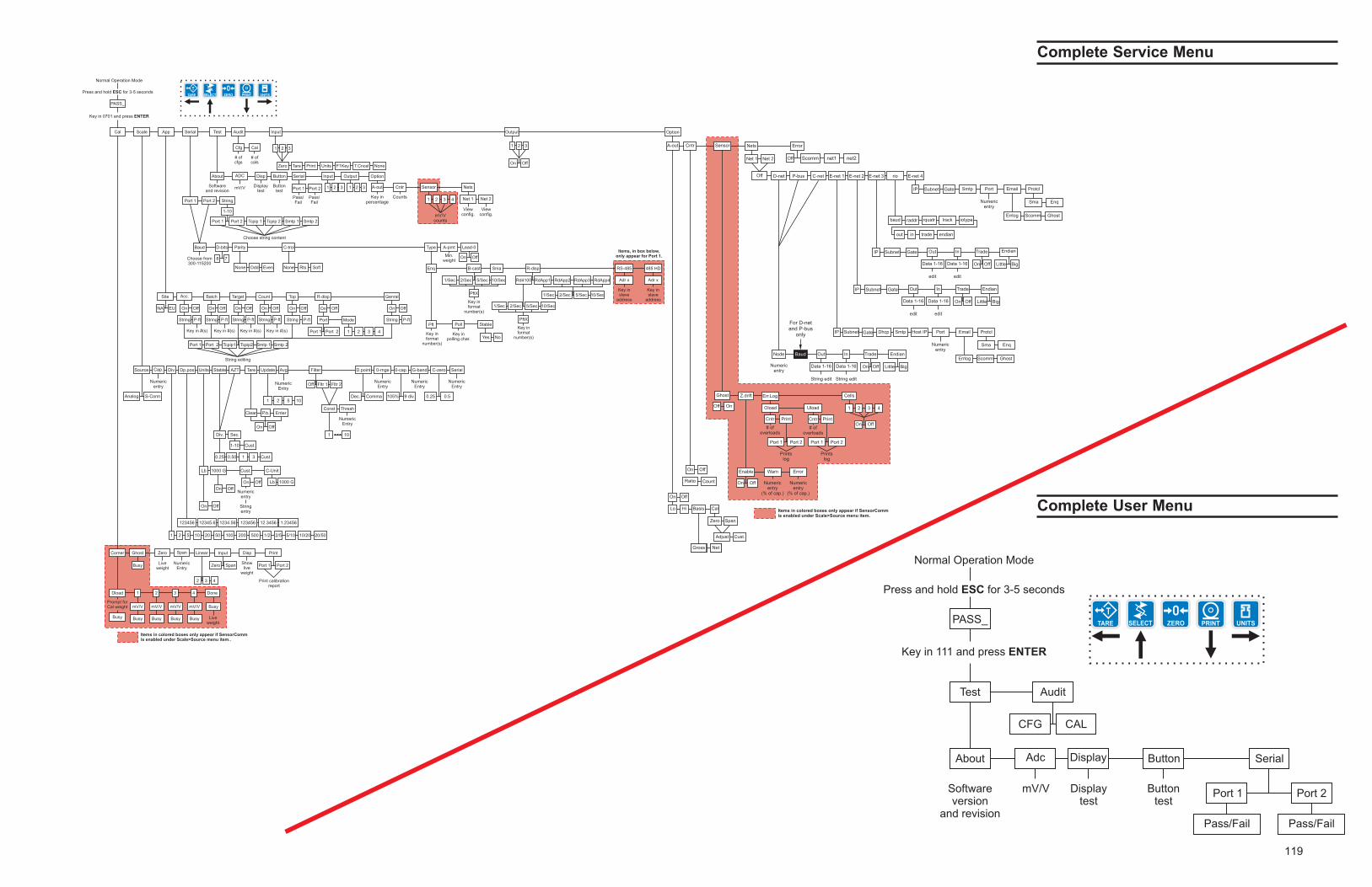
119
Complete Service Menu
Complete User Menu

120
MODEL E1070 SST INDICATORENCLOSURE PARTS AND ASSEMBLY
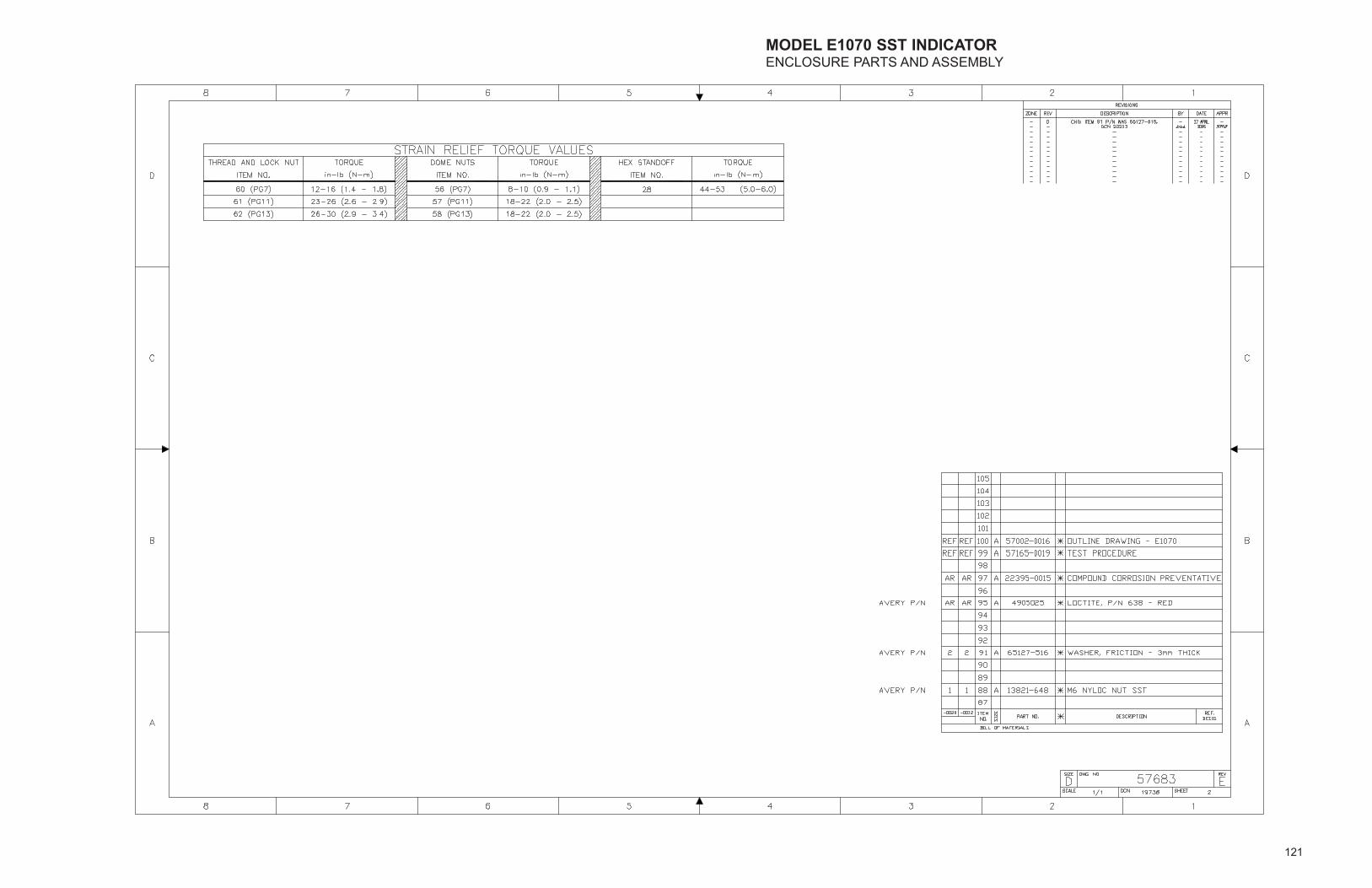
121
MODEL E1070 SST INDICATORENCLOSURE PARTS AND ASSEMBLY

122
MODEL E1070 SST INDICATORENCLOSURE PARTS AND ASSEMBLY

123
MODEL E1070 SST INDICATORENCLOSURE PARTS AND ASSEMBLY
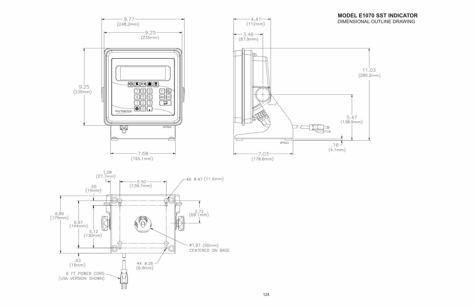
124
MODEL E1070 SST INDICATORDIMENSIONAL OUTLINE DRAWING

125
MODEL E1070 SST INDICATORWALL-MOUNT APPLICATION

126
MODEL E1070 SST INDICATORSYSTEM BLOCK DIAGRAM
WEIGHT SENSOR-TO-TB1 (TOP) WIRE COLOR CHART
SMA wire colorW-T wire color
-EXC
BLKBLK
+SENSE+EXC
GRNGRN
YELBLU
SHIELD/GND-SENSE +SIGNAL
WHTWHT
BLUBRN
WHT/ORNWHT/ORN
-SIGNAL
REDRED
cannot be installed at the same time as the"Analog Output/Pulse Input Kit".
NOTE: the "ControlNet kit" or "Remote I/O" kit
The "Network Interface Bd." must be installedPRIOR to "ControlNet" Bd. or "Remote I/O Bd.
Remote I/O board, and mtg. hardware.
REMOTE I/O FIELD INSTALL KIT:ControlNet FIELD INSTALL KIT:
Includes "Network Interface" board,ControlNet board and mtg. hardware.
Includes "Network Interface" board,P/N 57315-0034 P/N 57315-0059
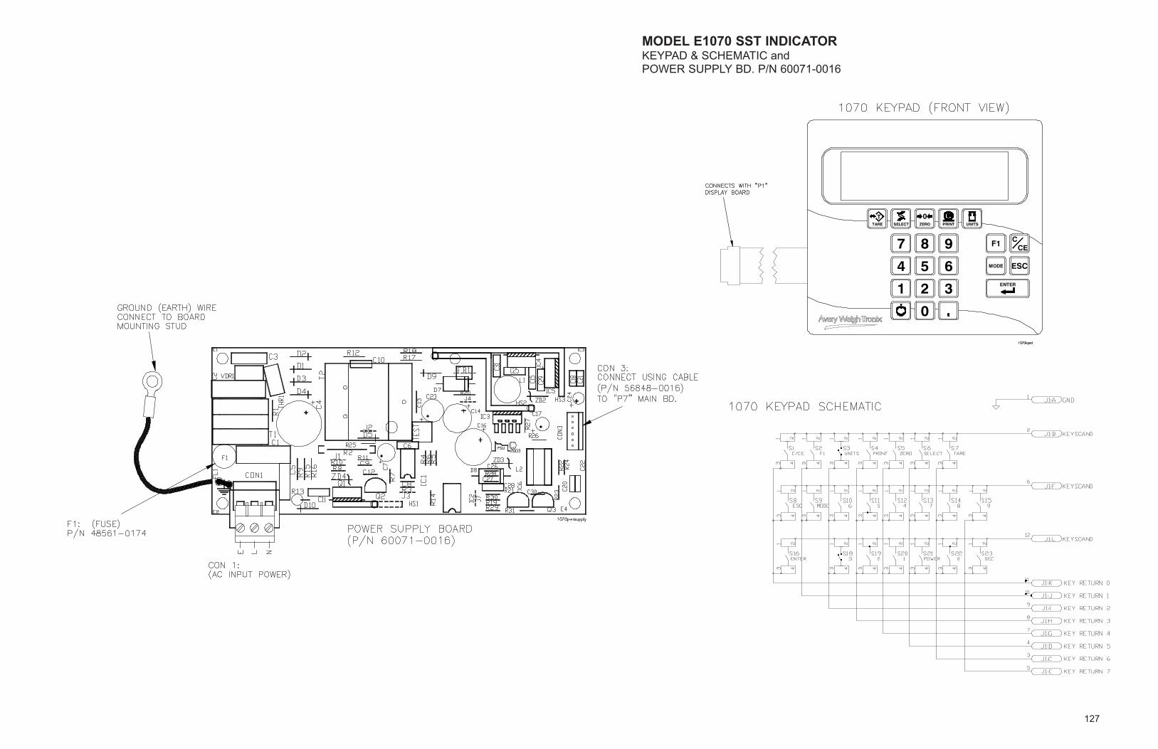
127
MODEL E1070 SST INDICATORKEYPAD & SCHEMATIC andPOWER SUPPLY BD. P/N 60071-0016
ENTER
C
ESCMODE
F1CE
1 2 3
0
654
987
T 0TARE SELECT ZERO PRINT UNITS

128
MODEL E1070 SST INDICATORMAIN BOARD ASSYP/N 57643-0011
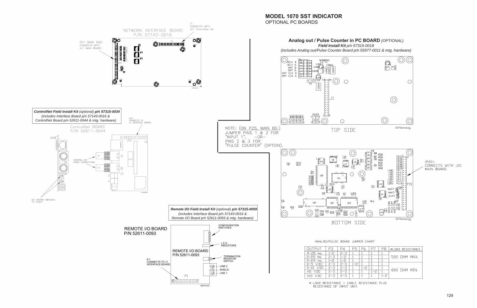
129
MODEL 1070 SST INDICATOROPTIONAL PC BOARDS
Analog out / Pulse Counter in PC BOARD (OPTIONAL)Field Install Kit p/n 57315-0018
(includes Analog out/Pulse Counter Board p/n 55977-0011 & mtg. hardware)
ControlNet Field Install Kit (optional) p/n 57315-0034(includes Interface Board p/n 57143-0016 &
ControlNet Board p/n 52611-0044 & mtg. hardware)
Remote I/O Field Install Kit (optional) p/n 57315-0059(includes Interface Board p/n 57143-0016 &
Remote I/O Board p/n 52611-0093 & mtg. hardware)
P/N 52611-0093REMOTE I/O BOARD
CONFIGURATIONSWITCHES
INDICATORSL.E.D.
RESISTORTERMINATION
SWITCH
LINE 2SHIELDLINE 1
CONNECTS TO J1P1:
INTERFACE BOARD.
P/N 52611-0093REMOTE I/O BOARD
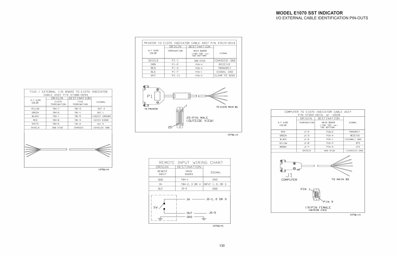
130
MODEL E1070 SST INDICATORI/O EXTERNAL CABLE IDENTIFICATION PIN-OUTS
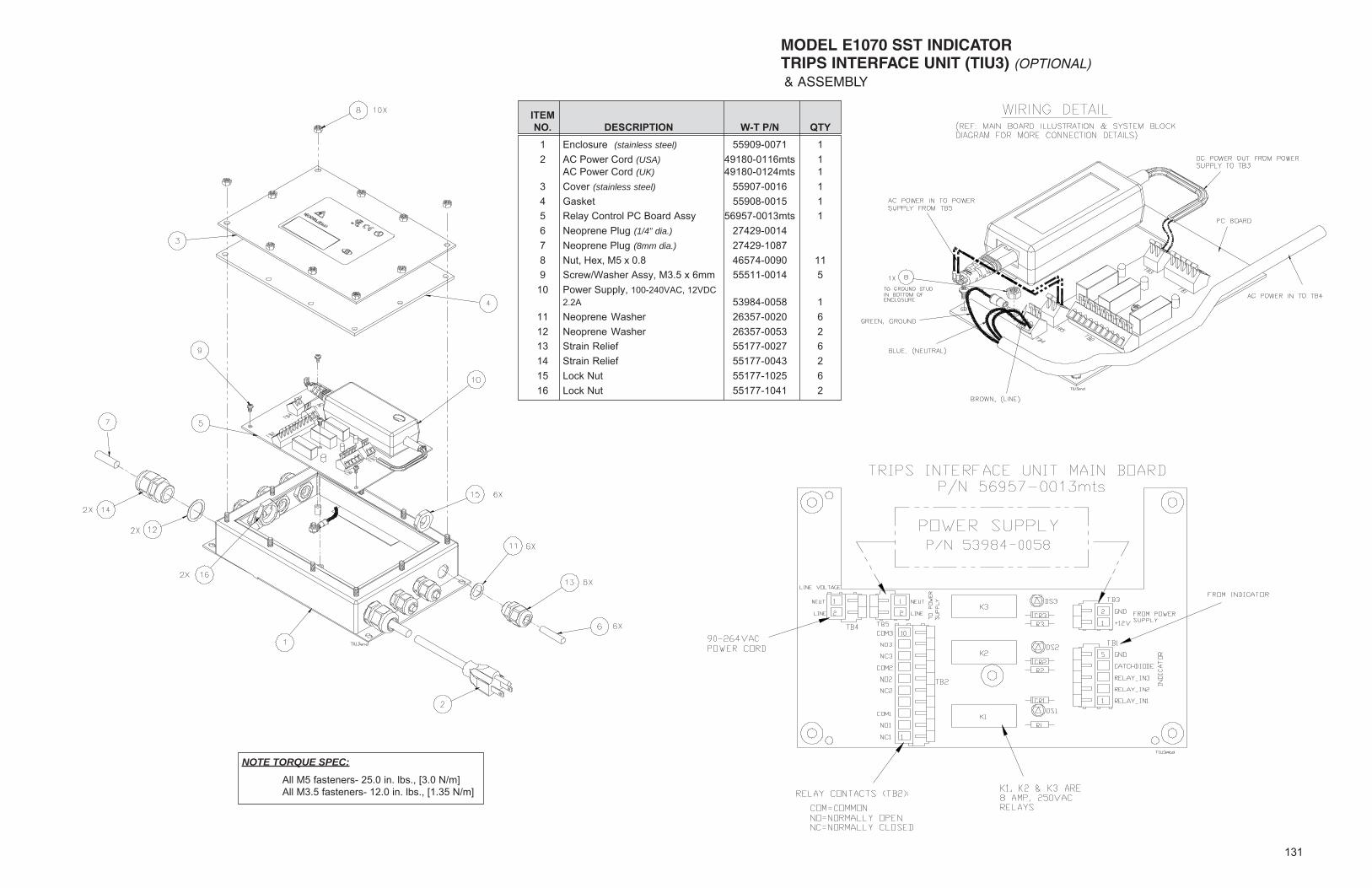
131
MODEL E1070 SST INDICATORTRIPS INTERFACE UNIT (TIU3) (OPTIONAL)& ASSEMBLY
NOTE TORQUE SPEC:
All M5 fasteners- 25.0 in. lbs., [3.0 N/m]All M3.5 fasteners- 12.0 in. lbs., [1.35 N/m]
ITEMNO. DESCRIPTION W-T P/N QTY
1 Enclosure (stainless steel) 55909-0071 12 AC Power Cord (USA) 49180-0116mts 1
AC Power Cord (UK) 49180-0124mts 13 Cover (stainless steel) 55907-0016 14 Gasket 55908-0015 15 Relay Control PC Board Assy 56957-0013mts 16 Neoprene Plug (1/4” dia.) 27429-00147 Neoprene Plug (8mm dia.) 27429-10878 Nut, Hex, M5 x 0.8 46574-0090 119 Screw/Washer Assy, M3.5 x 6mm 55511-0014 5
10 Power Supply, 100-240VAC, 12VDC2.2A 53984-0058 1
11 Neoprene Washer 26357-0020 612 Neoprene Washer 26357-0053 213 Strain Relief 55177-0027 614 Strain Relief 55177-0043 215 Lock Nut 55177-1025 616 Lock Nut 55177-1041 2

Weigh Bar® is a registered trademarkof Avery Weigh-Tronix and may beregistered in certain jurisdictions.
ODVA™, Ethernet/IP™ and DeviceNet™ are trademarks of ODVA.PROFIBUS® is a registered trademark of PROFIBUS International.
Avery Weigh-Tronix USA1000 Armstrong Dr.Fairmont, MN 56031 USATelephone: 507-238-4461Facsimile: 507-238-4195e-mail: [email protected]
Avery Weigh-Tronix UKFoundry LaneSmethwick, West MidlandsEngland B66 2LPTel: +44 870 90 34343Fax: +44 121 224 8183Email: [email protected] site:www.averyweigh-tronix.com
Avery Weigh-Tronix Canada, ULC217 Brunswick BoulevardPointe Claire, QC H9R 4R7 CanadaTelephone: 514-695-0380Toll free: 800-561-9461Facsimile: 514-695-6820www.weigh-tronix.ca