Embed Size (px)
Citation preview
Model-Driven Engineering of a Railway Interlocking System
Fabio Scippacercola1, Roberto Pietrantuono1, Stefano Russo1, Andras Zentai21DIETI, Universita degli Studi di Napoli Federico II, Via Claudio 21, 80125 Napoli, Italy
2Prolan Process Control Co., Szentendrei ut 1-3, H-2011 Budakalasz, Hungary{fabio.scippacercola, roberto.pietrantuono, stefano.russo}@unina.it, [email protected]
Keywords: Model-Driven Design; Model-Driven Testing; Model-Driven Architecture; Safety-critical systems.
Abstract: Model-Driven Engineering (MDE) promises to enhance system development by reducing development time,and increasing productivity and quality. MDE is gaining popularity in several industry sectors, and is attractivealso for critical systems where they can reduce efforts and costs for verification and validation (V&V), andcan ease certification. Incorporating model-driven techniques into a legacy well-proven development cycle isnot simply a matter of placing models and transformations in the design and implementation phases.We present the experience in the model-driven design and V&V of a safety-critical system in the railwaydomain, namely the Prolan Block, a railway interlocking system manufactured by the Hungarian companyProlan Co., required to be CENELEC SIL-4 compliant. The experience has been carried out in an industrial-academic partnership within the EU project CECRIS. We discuss the challenges and the lessons learnt in thispilot project of introducing MD design and testing techniques into the company’s traditional V-model process.
1 INTRODUCTION
Model-Driven Engineering (MDE) promises to en-hance system development and testing by improv-ing quality and increasing productivity. It has gainedpopularity in some industry sectors, and is appealingalso for critical systems, where it can reduce effortsand costs for development, verification and valida-tion, and can provide support for product certification.
MDE is attractive due to the benefits it can pro-vide in terms of quality of artifacts and of support forautomation. Several issues need however to be ad-dressed in order to increase the industrial consensuson their applicability. Many companies still considerits adoption risky, as it requires changes in consol-idated processes, and advanced engineering skills –focus is on modeling, rather than on implementation.Full comprehension of MDE risks and benefits is anon trivial task, especially for safety-critical systems,demanding for high levels of integrity and for certifi-cation. More empirical studies are needed to increasethe knowledge on MDE success and failure factors(Mohagheghi and Dehlen, 2008).
In this paper we discuss the challenges and lessonslearnt in introducing MDE for development and test-ing in a real industrial context. Benefits and draw-backs have been assessed in a pilot project conductedin Prolan Control Co., a Hungarian company manu-
facturing process control and rail signaling systems.In the industrial-academic partnership within the Eu-ropean project “CErtification of CRItical Systems”(CECRIS)1, this pilot experience aimed at introduc-ing innovation in the development process of ProlanBlock, a safety-critical system for railway interlock-ing that must be CENELEC EN50126, EN50128 andEN50129 SIL-4 certified.
The proposed process, tailored to the applica-tion domain needs, provided a complete applicablemethodology to support verification and validation ina conventional V-Model, as suggested by CENELECstandards. We discuss the challenges emerged, espe-cially related to organizational factors and to the de-gree of maturity of the supported tools. The resultsprovide hints about the application of model-drivenapproaches, useful for companies and practitionersthat develop systems in safety-critical domains.
The rest of the paper is structured as follows. Sec-tion 2 recalls concepts about Model-Driven Engineer-ing, while Section 3 surveys the related work. Sec-tion 4 describes the proposed development process;Section 5 shows its application to the pilot project.Section 6 discusses lessons learnt and on the chal-lenges we faced. Section 7 concludes the papers anddiscusses about future work.
1website: www.cecris-project.eu
2 BACKGROUND
Model-Driven Engineering (MDE) refers to engineer-ing processes and activities in which models are keyartifacts of the work (Brambilla et al., 2012). Model-Driven Architecture (MDA) is the particular Model-Driven Development (MDD) approach proposed bythe object standardization organization OMG (OMG,2003).
MDE is founded on concepts of models and trans-formations: instead of producing (textual) documentsas artifacts – requirements, design, code, test arti-facts – in MDE engineers focus on models as pri-mary artifacts. Models are defined in (semi-)formallanguages, that are typically machine-understandableand drawn with the support of tools. Other artifactsare derived through defined transformations: model-to-model transformations (M2M), or model-to-texttransformation (M2T) from models to textual docu-ments, source code or testing artifacts (such as testcases and test scripts).
MDA is based on OMG standards and focuses onsoftware development. It introduces several abstrac-tion levels for the separation of concerns in forwardengineering: the Computation Independent Model(CIM), Platform Independent Model (PIM) and Plat-form Specific Model (PSM). The CIM is at the high-est level of abstraction; it neglects the processing andthe internal structure of the system and offers a modelthat is independent by computation details. It focuseson the environment and on requirements, using a vo-cabulary that is familiar to system’s domain practi-tioners. The PIM takes into account the computationdetails: it is a model that focuses on the operationsof the system, but abstracts the relations that concerna particular technology or execution platform, suchas the hardware interface, the programming languageand the middleware. Finally, several PSMs may bedefined by refining the PIM, each one bound to spe-cific implementation technologies and platforms. Ingeneral, as argued by (Kent, 2002), MDE approachescan identify different levels of decomposition and canemploy ad hoc or domain specific languages for mod-els and transformations, whereas MDA is bound toOMG’s standards.
MDA adopts the Unified Modeling Language(UML), a general purpose language for software en-gineering. The version 2.0 of UML (OMG, 2005)introduced several improvements in the language inorder to enable UML to MDA (France et al., 2006).One of the characteristics of UML is its capabilityto be easily extended by mechanisms defined in thestandard: by UML Profiles, Tagged Values and Con-straints, custom domain specific languages (DSLs)
can be defined, reusing and extending the elementsof the UML language.
Another OMG’s standard of interest to our work isSysML (OMG, 2008). This modeling language par-tially overlaps with UML 2.0, but it focuses on systemengineering, providing specific support for capturingfunctional and performance requirements, quantita-tive constraints, and information flows.
Model-Driven Testing (MDT) is a MDE activityfor V&V (Baker et al., 2007). It is not an OMG stan-dard, but it is based on a UML standard profile, theUML Testing Profile (UTP), which adapts UML as atest specification language. In MDT, test infrastruc-ture, test cases, and test scripts are derived by UTPmodels through transformations.
3 RELATED WORK
There are several experience reports on the applica-tion of MDE in complete or pilot projects. A sys-tematic review of them can be found in (Mohagheghiand Dehlen, 2008). MDE is generally perceived aspositive in practice, especially because it improvesthe productivity, shortens the development time, in-creases the quality of generated artifacts, and auto-mates several activities in the development process.However, some critical open challenges have beenalso identified. For instance, in some cases the auto-matic code generation, an important feature of MDE,turned out to be partial, requiring the use of DSLs;in other cases, the development processes were per-ceived as no suited for MDE, because not thought toexploit model-driven techniques.
Indeed, MDE lacks of well-defined processes andit is generally introduced adapting traditional devel-opment processes. A survey on few MDA-Based de-velopment processes is in (Asadi and Ramsin, 2008).In (Carrozza et al., 2012; Carrozza et al., 2013) anadaptation is described of a V-Model process com-pliant with MIL-STD-498 for exploiting MDA andMDT approaches for air traffic control domain. Webuild on that work for the definition of the processpresented hereafter.
The study in (Whittle et al., 2014) surveyed MDEpractices from a rather wide spread of companies.Authors notice how MDE is not confined to a nichemarket but is generally adopted everywhere. The ma-jor part of practitioners make large use of DSLs, andbelieve that benefits of MDE are not mainly in codegeneration. It is interesting to note how data suggestthat the structure and business of an organization havean impact on the success of MDE: model-driven ap-proaches seem more appropriate for companies that
target specific domains than companies developinggeneric software. The results of a previous study (Ag-ner et al., 2013) slightly differs from the mentionedsurvey. The latter noticed a little adoption of MDE inBrazilian companies that develop embedded software.Few differences can be also found in a preliminarysurvey of model-driven approaches in Italian indus-try (Torchiano et al., 2011): here UML is preferredto DSLs. This heterogeneity may be a symptom ofareas of immaturity of model-driven approaches withrespect to their industrial application, thus more in-vestigation is required.
MDE has been applied to safety-critical systems,for which verification and validation activities are cru-cial and account for a large part of costs, and whereMDE is hoped to provide benefits also in view of cer-tification. To this aim, specific challenges have to befaced. For instance, model transformations, like au-tomatic code generation, must be properly addressedconsidering the rules of certification standards.
In the railway domain MDE has been widely ex-perimented. Authors in (Ferrari et al., 2013) report asuccessful application of Simulink/Stateflow modelsfor the development of an on-board equipment of anautomatic Train Protection System. By adopting par-ticular restrictions and solutions on models, and byusing a model-based testing approach called Transla-tion Validation, the authors were able to certificate thesystem according to the CENELEC standards. An-other interesting application of MDD for the auto-matic generation of proper configuration of computerbased interlocking systems is presented in (Svendsenet al., 2008), in which secondary artifacts were auto-matically generated by model transformation in orderto support CENELEC certification.
As for certification, important advantages of MDapproaches lie in the support for requirements trace-ability and for formal methods in V&V activities.With respect to formal methods, in (Marrone et al.,2014), a MDE technique is proposed for the assess-ment of railway control systems. It is based on spe-cialized UML profiles that enable translations to spe-cific formalisms, with the goal of supporting V&Vthrough the automatic generation of test cases andthrough model checking. Similarly, a solution for in-tegrating model checking with various synchronousdataflow languages adopted by commercial MDDtools (MATLAB Simulink or SCADE) is discussed inthe airborne domain in (Miller et al., 2010). It is worthnoting that SCADE (Esterel Technologies, 2014) isthe first MDD tool qualified for standard DO-178B.Other interesting approaches that focus on how to en-hance traceability and documentation capabilities ofMDE to ease safety inspections and certification pro-
cesses can be found in (Nejati et al., 2012; Panesar-Walawege et al., 2011).
Despite good solutions for solving isolated prob-lems and few examples of certification-compliantMDE-based processes, certification is still an openchallenge for MDE. For instance, automatic code gen-eration can even lead to an increase of efforts andcosts for certification, as reported in (Whittle et al.,2014). Therefore, benefits and drawbacks that model-driven techniques bring must be specifically evaluateddepending on the applications.
4 MODEL-DRIVEN APPROACH
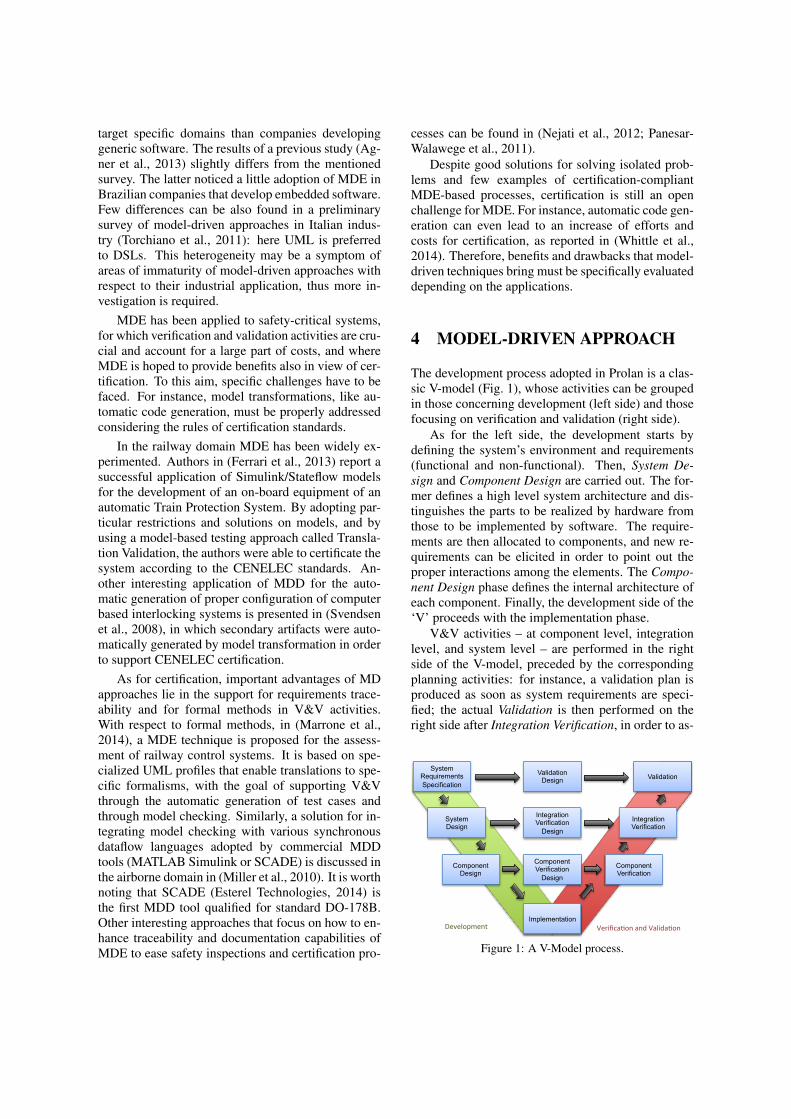
The development process adopted in Prolan is a clas-sic V-model (Fig. 1), whose activities can be groupedin those concerning development (left side) and thosefocusing on verification and validation (right side).
As for the left side, the development starts bydefining the system’s environment and requirements(functional and non-functional). Then, System De-sign and Component Design are carried out. The for-mer defines a high level system architecture and dis-tinguishes the parts to be realized by hardware fromthose to be implemented by software. The require-ments are then allocated to components, and new re-quirements can be elicited in order to point out theproper interactions among the elements. The Compo-nent Design phase defines the internal architecture ofeach component. Finally, the development side of the‘V’ proceeds with the implementation phase.
V&V activities – at component level, integrationlevel, and system level – are performed in the rightside of the V-model, preceded by the correspondingplanning activities: for instance, a validation plan isproduced as soon as system requirements are speci-fied; the actual Validation is then performed on theright side after Integration Verification, in order to as-
Validation Design
System Requirements Specification
System Design
Component Design
Implementation
Component Verification
Integration Verification
Validation
Integration Verification
Design
Component Verification
Design
Development* Verifica1on*and*Valida1on*
Figure 1: A V-Model process.
sess the product conformance to requirements.Our work is based on an adaptation of the de-
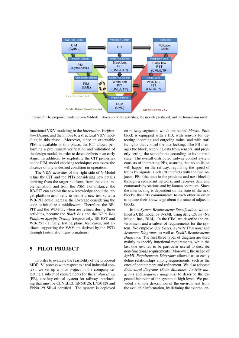
scribed V-model to introduce MDA and MDT tech-niques (Fig. 2). On the left side of the V-model wefollow the MDA approach. At each step we focus onone of the three viewpoints of the system (Compu-tation Independent Viewpoint, Platform IndependentViewpoint and Platform Specific Viewpoint), used todefine the CIM, the PIM and the PSM. The same ab-stractions are adopted for defining the key models inthe activities of the center and right side of the ‘V’,but both focusing on V&V activities. The methodol-ogy allows engineers to define additional models inorder to support the V&V activities by exploiting dif-ferent views of the system.
In System Requirements Specification, we definea CIM for modeling the environment and the systemrequirements. The CIM is defined in SysML; thislanguage is particularly suited in this phase, as it of-fers requirements diagrams and allows to model bothhardware and software components.
System Design refines the CIM into a PIM, addingcomputation details by defining the components andthe high level architecture of the system. The require-ments are assigned to the elements of the system ina way to keep them traceable. In this phase the PIMdescribes, for each component, the requirements, theinterfaces, and the behavior, namely, the expected I/Orelations at components’ interfaces. UML ProtocolState Machines are suited at this stage, because theycan describe I/O relations without providing an inter-nal description of the elements of the system.
Component Design completes the PIM with theinternal design on the elements. Considering the soft-ware, this model is expressed in UML and should bespecific enough to be subject to simulation and modelchecking. Since the Component Design focuses ondescribing the dynamic behavior of the elements, itcan exploit UML Behavioral State Machines.
In the Implementation phase, the PIM is refinedinto one or more PSMs, which are bound to targetplatforms, adding low level details to the PIM con-cerning implementation. For instance, a PSM adaptsthe generic types of the variables with the actual onesprovided by a programming language, and binds dataand function calls to the interfaces of the middlewareand OS that have been chosen for the instantiation.The PSM can be translated into code to provide a par-tial or a total implementation of the system.
The Validation Design exploits the CIM to de-fine an environment model named Computation In-dependent Testing model (CIT). The CIT is unawareof computation details; it models the behavior of theactors and of the environment. System requirements
are expressed as properties or conditions in the model,such as “no collisions between trains” must occur.The CIT is useful to validate the system against itsexpected usage by external actors, and to create a sim-ulated environment in which engineers can assess thesystem’s behavior. The model also enables engineersto perform special kinds of assessment, like perfor-mance testing, because CIT can generate a represen-tative operational profile for the system.
Integration Verification Design defines a modelof the expected behavior of the system’s compo-nents, independent from their inner design. We re-fer to it as Black Box Platform Independent Test-ing model (BB-PIT). This model provides static anddynamic views of the system’s components, and itis mainly used to support functional testing in theunit/integration/system verification. The static de-scription supports the generation of the testing infras-tructure, such as stubs and drivers for unit and inte-gration testing. The dynamic description is composedby: (i) behavioral models, such as UML BehavioralState Machines, defined starting by requirements as-signed to each component in the PIM model; (ii) testcases, which are specified by Sequence, Activity andState Machines diagrams using the UTP profile. Be-havioral models are useful to support the definitionof testing and verification plans and for the automaticgeneration of test cases. A BB-PIT can model the be-havior of one component with more state machines,each focusing on a different subset of functionalities,with the possibility of composing test suites by group-ing tests derived by several state machines. In addi-tion, a BB-PIT supports the detection of design faultsby comparing the behavior it describes with the onedefined in the PIM. In fact, the behavior of a com-ponent is modeled differently in the PIM and in theBB-PIT, due to the different purposes they support: aPIM specifies how to build the system, and representsthe specification that an actual implementation mustcomply with; a BB-PIT describes the expected be-havior in a way to verify its correspondence betweenrequirements and implementation (e.g., by using theBB-PIT for test case generation, the description rep-resents the specification that test cases must complywith). It is finally worth noting that, since BB-PITderives from requirements and is barely influenced bydesign details, it can support validation too.
Component Verification Design refines the BB-PIT defining a White Box PIT model (WB-PIT), sinceit benefits from the PIM at Component Design-level,which provides a white box view of the system. TheWB-PIT enables additional verification techniquesthat can exploit structural features for assessing cor-rectness. Following this flow, engineers focus on a
CIT CIM (SysML)
PIM (SysML/UML)
PIM (UML)
PSM (UML)
White box PST
(UML/UTP)
Black box PST
(UML/UTP)
Validation Model
Black box PIT
(UML/UTP)
White box PIT
(UML/UTP)
Model&Driven&Development& Model&Driven&V&V&
Early&detec5on&of&faults&
Sys. Req. Spec. &
System Design&
Component Design&
Validation Design&
Integr. Ver. Design&
Comp. Ver. Design&
Implementation&
Comp. Verif.&
Integration Verif.&
Validation&
Figure 2: The proposed model-driven V-Model. Boxes show the activities, the models produced, and the formalisms used.
functional V&V modeling in the Integration Verifica-tion Design, and then move to a structural V&V mod-eling in this phase. Moreover, since an executablePIM is available in this phase, the PIT allows per-forming a preliminary verification and validation ofthe design model, in order to detect defects at an earlystage. In addition, by exploiting the CIT propertieson the PIM, model checking techniques can assess theabsence of any undesired condition in operation.
The V&V activities of the right side of V-Modelrefine the CIT and the PITs considering new detailsderiving from the target platform, from the code im-plementation, and from the PSM. For instance, theBB-PIT can exploit the new knowledge about the tar-get platform arithmetic to define a new test suite; aWB-PIT could increase the coverage considering thecode to initialize a middleware. Therefore, the BB-PIT and the WB-PIT, when are refined during theseactivities, become the Black Box and the White BoxPlatform Specific Testing (respectively, BB-PST andWB-PST). Finally, testing plans, test cases, and ar-tifacts supporting the V&V are derived by the PSTsthrough (automatic) transformations.
5 PILOT PROJECT
In order to evaluate the feasibility of the proposedMDE ‘V’ process with respect to a real industrial con-text, we set up a pilot project in the company se-lecting a subset of requirements for the Prolan Block(PB), a safety-critical system for railway interlock-ing that must be CENELEC EN50126, EN50128 andEN50129 SIL-4 certified. The system is deployed
on railway segments, which are named blocks. Eachblock is equipped with a PB, with sensors for de-tecting incoming and outgoing trains, and with traf-fic lights that control the interlocking. The PB man-ages the block, receiving data from sensors, and prop-erly setting the semaphores according to its internalstate. The overall distributed railway control systemconsists of interacting PBs, assuring that no collisionwill happen on the railway, regulating the speed oftrains by signals. Each PB interacts with the two ad-jacent PBs (the ones in the previous and next blocks)through a redundant network, and receives data andcommands by stations and by human operators. Sincethe interlocking is dependent on the state of the nextblocks, the PBs communicate to each other in orderto update their knowledge about the state of adjacentblocks.
In the System Requirements Specification, we de-fined a CIM model by SysML using MagicDraw (NoMagic, Inc., 2014). In the CIM, we describe the en-vironment and a subset of requirements for the sys-tem. We employe Use Cases, Activity Diagrams andSequence Diagrams, as well as SysML RequirementsDiagrams. The first three types of diagram are usedmainly to specify functional requirements, while thelast one resulted to be particular useful to describenon-functional requirements. Moreover, the usage ofSysML Requirements Diagrams allowed us to easilydefine relationships among requirements, such as theones of containment and refinement. We also adoptedBehavioral diagrams (State Machines, Activity dia-grams and Sequence diagrams) to describe the ex-pected behavior of the system at high level. We pro-vided a simple description of the environment fromthe available information, by defining the external en-
MagicDraw, 1-1 /Users/nonplay/Documents/Dropbox/Prolan Work/Shared Andras_Fabio/Models/Prolan Block/ProlanTerkoz.mdzip Next is a 3-aspect signal 19-ago-2014 13.10.23
Next is a 3-aspect signal Next is a 3-aspect signal[State Machine] stm [ ]
YellowGreen
Red
According to the direction
Dark
On-state
OFF-state
switch off
switch off
change of direction
Block is freeBlock is occupied
Next signal is yellow
Block is occupied
change of directionswitch off
change of direction
switch offswitch on
switch offchange of direction
change of direction
switch off
switch on
switch on
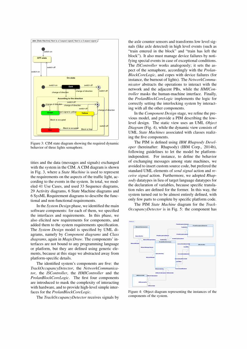
Figure 3: CIM state diagram showing the required dynamicbehavior of three lights semaphore.
tities and the data (messages and signals) exchangedwith the system in the CIM. A CIM diagram is shownin Fig. 3, where a State Machine is used to representthe requirements on the aspects of the traffic light, ac-cording to the events in the system. In total, we mod-eled 41 Use Cases, and used 33 Sequence diagrams,29 Activity diagrams, 6 State Machine diagrams and6 SysML Requirement diagrams to describe the func-tional and non-functional requirements.
In the System Design phase, we identified the mainsoftware components: for each of them, we specifiedthe interfaces and requirements. In this phase, wealso elicited new requirements for components, andadded them to the system requirements specification.The System Design model is specified by UML di-agrams, namely by Component diagrams and Classdiagrams, again in MagicDraw. The components’ in-terfaces are not bound to any programming languageor platform, but they are defined using generic ele-ments, because at this stage we abstracted away fromplatform-specific details.
The identified system’s components are five: theTrackOccupancyDetector, the NetworkCommunica-tor, the ISController, the HMIController and theProlanBlockCoreLogic. The first four componentsare introduced to mask the complexity of interactingwith hardware, and to provide high-level simple inter-faces for the ProlanBlockCoreLogic.
The TrackOccupancyDetector receives signals by
the axle counter sensors and transforms low level sig-nals (like axle detected) in high level events (such as“train entered in the block” and “train has left theblock”). It also must manage device failures by noti-fying special events in case of exceptional conditions.The ISController works analogously; it sets the as-pect of the semaphore, accordingly with the Prolan-BlockCoreLogic, and copes with device failures (forinstance, the burnout of lights). The NetworkCommu-nicator abstracts the operations to interact with thenetwork and the adjacent PBs, while the HMICon-troller masks the human-machine interface. Finally,the ProlanBlockCoreLogic implements the logic forcorrectly setting the interlocking system by interact-ing with all the other components.
In the Component Design stage, we refine the pre-vious model, and provide a PIM describing the low-level design. The static view uses an UML ObjectDiagram (Fig. 4), while the dynamic view consists ofUML State Machines associated with classes realiz-ing the five components.
The PIM is defined using IBM Rhapsody Devel-oper (hereinafter: Rhapsody) (IBM Corp., 2014b),following guidelines to let the model be platform-independent. For instance, to define the behaviorof exchanging messages among state machines, weavoided to insert custom source code, but prefered thestandard UML elements of send signal action and re-ceive signal action. Furthermore, we adopted Rhap-sody datatypes in lieu of target language datatypes forthe declaration of variables, because specific transla-tion rules are defined for the former. In this way, thesystem turned out to be almost entirely defined, withonly few parts to complete by specific platform code.
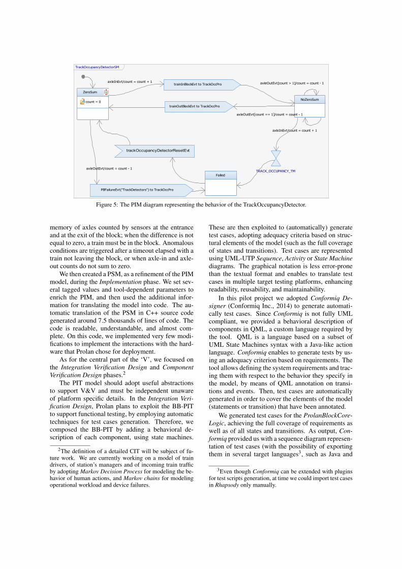
The PIM State Machine diagram for the Track-OccupancyDetector is in Fig. 5: the component has
PBObjects
:ProlanBlockCoreLogic1
HMIControllerReq
IHMIControllerListener IHMIController
IConventionalISListener
IConventionalISController
ConvISReq
ITrackOccupanyListener
ITrackOccupancyDetector
TrackOccReq
INetworkManagerListener
INetworkManager
NetworkPortReq
IHMIControllerIHMIControllerListener
HMIControllerReq
ConvISReq
IConventionalISController
IConventionalISListener
ITrackOccupanyListener
ITrackOccupancyDetector
TrackOccReq
INetworkManager
NetworkPortReq
INetworkManagerListener
:TrackOccupancyDetector1ITrackOccupancyDetector
ITrackOccupanyListener
TrackOccPro
ITrackOccupancyDetector
TrackOccPro
ITrackOccupanyListener
:ISController1IConventionalISController
IConventionalISListener
ConvISPro
IConventionalISController
ConvISPro
IConventionalISListener
:NetworkCommunicator1
INetworkManager
INetworkManagerListener
NetworkPortPro
INetworkManager
INetworkManagerListener
NetworkPortPro
:HMIController1
IHMIController
IHMIControllerListener
HMIControllerPro
IHMIController
IHMIControllerListener
HMIControllerPro
Figure 4: Object diagram representing the instances of thecomponents of the system.
TrackOccupancyDetectorSM
ZeroSum
count = 0NoZeroSum
axleInEvt/count = count + 1
axleOutEvt[count > 1]/count = count - 1
Failed
PBFailureEvt("TrackDetectors") to TrackOccPro
axleOutEvt/count = count - 1
trainInBlockEvt to TrackOccProaxleInEvt/count = count + 1
trainOutBlockEvt to TrackOccPro
axleOutEvt[count == 1]/count = count - 1
TRACK_OCCUPANCY_TM
trackOccupancyDetectorResetEvt
Figure 5: The PIM diagram representing the behavior of the TrackOccupancyDetector.
memory of axles counted by sensors at the entranceand at the exit of the block; when the difference is notequal to zero, a train must be in the block. Anomalousconditions are triggered after a timeout elapsed with atrain not leaving the block, or when axle-in and axle-out counts do not sum to zero.
We then created a PSM, as a refinement of the PIMmodel, during the Implementation phase. We set sev-eral tagged values and tool-dependent parameters toenrich the PIM, and then used the additional infor-mation for translating the model into code. The au-tomatic translation of the PSM in C++ source codegenerated around 7.5 thousands of lines of code. Thecode is readable, understandable, and almost com-plete. On this code, we implemented very few modi-fications to implement the interactions with the hard-ware that Prolan chose for deployment.
As for the central part of the ‘V’, we focused onthe Integration Verification Design and ComponentVerification Design phases.2
The PIT model should adopt useful abstractionsto support V&V and must be independent unawareof platform specific details. In the Integration Veri-fication Design, Prolan plans to exploit the BB-PITto support functional testing, by employing automatictechniques for test cases generation. Therefore, wecomposed the BB-PIT by adding a behavioral de-scription of each component, using state machines.
2The definition of a detailed CIT will be subject of fu-ture work. We are currently working on a model of traindrivers, of station’s managers and of incoming train trafficby adopting Markov Decision Process for modeling the be-havior of human actions, and Markov chains for modelingoperational workload and device failures.
These are then exploited to (automatically) generatetest cases, adopting adequacy criteria based on struc-tural elements of the model (such as the full coverageof states and transitions). Test cases are representedusing UML-UTP Sequence, Activity or State Machinediagrams. The graphical notation is less error-pronethan the textual format and enables to translate testcases in multiple target testing platforms, enhancingreadability, reusability, and maintainability.
In this pilot project we adopted Conformiq De-signer (Conformiq Inc., 2014) to generate automati-cally test cases. Since Conformiq is not fully UMLcompliant, we provided a behavioral description ofcomponents in QML, a custom language required bythe tool. QML is a language based on a subset ofUML State Machines syntax with a Java-like actionlanguage. Conformiq enables to generate tests by us-ing an adequacy criterion based on requirements. Thetool allows defining the system requirements and trac-ing them with respect to the behavior they specify inthe model, by means of QML annotation on transi-tions and events. Then, test cases are automaticallygenerated in order to cover the elements of the model(statements or transition) that have been annotated.
We generated test cases for the ProlanBlockCore-Logic, achieving the full coverage of requirements aswell as of all states and transitions. As output, Con-formiq provided us with a sequence diagram represen-tation of test cases (with the possibility of exportingthem in several target languages3, such as Java and
3Even though Conformiq can be extended with pluginsfor test scripts generation, at time we could import test casesin Rhapsody only manually.
Panel Diagram
RED
YELLOW
GREEN
Red Light Failed
Yellow Light Failed
Green Light Failed
Push
Red Light Failure
Push
Yellow Light Failure
Push
Green Light Failure
ProlanBlock in SafeState
Axles Counted
Push
AxleIn Event
Push
AxleOut Event
Push
NextPBYellowState
Push
NextPBRedState
Push
NextPBGreenState
Figure 6: The Rhapsody Panel diagram for the PB.
TTCN-3), and the traceability matrix, correlating testcases with the features they cover.
In the Component Verification Design, the PIT isrefined with extra details deriving from the PIM. Inthis activity we exploited the WB-PIT to generatestructural test cases to cover the elements of the de-sign model. To this aim, we adopted the AutomaticTest Generator (ATG) (IBM Corp., 2014a) of Rhap-sody for deriving additional test cases based on struc-tural coverage. ATG generated ten test cases for theProlanBlockCoreLogic, as IBM-UTP Sequence Di-agrams (IBM-UTP is a custom profile available inRhapsody). The achieved coverage on the PIM is of91%, with 19/21 states and 22/24 transitions beingcovered. The remaining states and transitions havebeen covered by manually-written test cases.
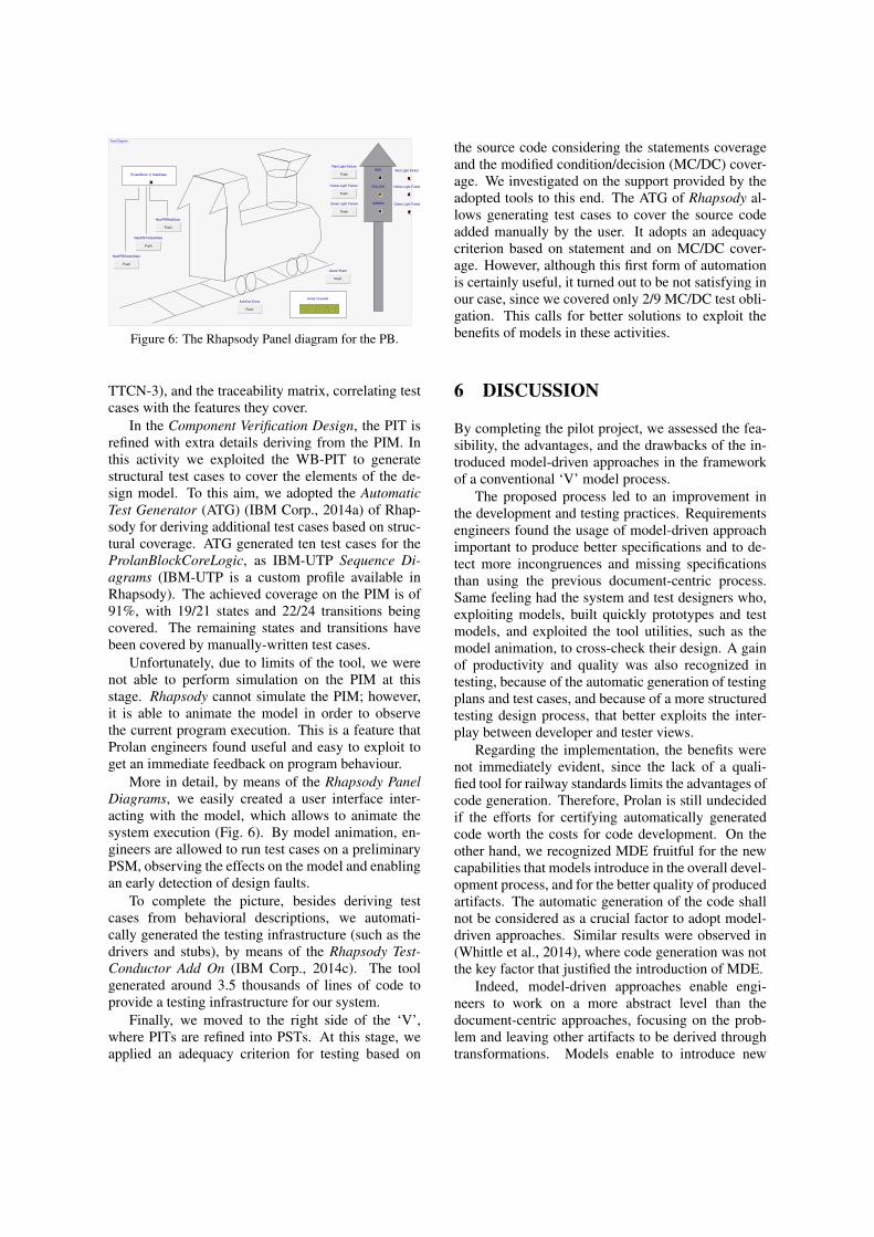
Unfortunately, due to limits of the tool, we werenot able to perform simulation on the PIM at thisstage. Rhapsody cannot simulate the PIM; however,it is able to animate the model in order to observethe current program execution. This is a feature thatProlan engineers found useful and easy to exploit toget an immediate feedback on program behaviour.
More in detail, by means of the Rhapsody PanelDiagrams, we easily created a user interface inter-acting with the model, which allows to animate thesystem execution (Fig. 6). By model animation, en-gineers are allowed to run test cases on a preliminaryPSM, observing the effects on the model and enablingan early detection of design faults.
To complete the picture, besides deriving testcases from behavioral descriptions, we automati-cally generated the testing infrastructure (such as thedrivers and stubs), by means of the Rhapsody Test-Conductor Add On (IBM Corp., 2014c). The toolgenerated around 3.5 thousands of lines of code toprovide a testing infrastructure for our system.
Finally, we moved to the right side of the ‘V’,where PITs are refined into PSTs. At this stage, weapplied an adequacy criterion for testing based on
the source code considering the statements coverageand the modified condition/decision (MC/DC) cover-age. We investigated on the support provided by theadopted tools to this end. The ATG of Rhapsody al-lows generating test cases to cover the source codeadded manually by the user. It adopts an adequacycriterion based on statement and on MC/DC cover-age. However, although this first form of automationis certainly useful, it turned out to be not satisfying inour case, since we covered only 2/9 MC/DC test obli-gation. This calls for better solutions to exploit thebenefits of models in these activities.
6 DISCUSSION
By completing the pilot project, we assessed the fea-sibility, the advantages, and the drawbacks of the in-troduced model-driven approaches in the frameworkof a conventional ‘V’ model process.
The proposed process led to an improvement inthe development and testing practices. Requirementsengineers found the usage of model-driven approachimportant to produce better specifications and to de-tect more incongruences and missing specificationsthan using the previous document-centric process.Same feeling had the system and test designers who,exploiting models, built quickly prototypes and testmodels, and exploited the tool utilities, such as themodel animation, to cross-check their design. A gainof productivity and quality was also recognized intesting, because of the automatic generation of testingplans and test cases, and because of a more structuredtesting design process, that better exploits the inter-play between developer and tester views.
Regarding the implementation, the benefits werenot immediately evident, since the lack of a quali-fied tool for railway standards limits the advantages ofcode generation. Therefore, Prolan is still undecidedif the efforts for certifying automatically generatedcode worth the costs for code development. On theother hand, we recognized MDE fruitful for the newcapabilities that models introduce in the overall devel-opment process, and for the better quality of producedartifacts. The automatic generation of the code shallnot be considered as a crucial factor to adopt model-driven approaches. Similar results were observed in(Whittle et al., 2014), where code generation was notthe key factor that justified the introduction of MDE.
Indeed, model-driven approaches enable engi-neers to work on a more abstract level than thedocument-centric approaches, focusing on the prob-lem and leaving other artifacts to be derived throughtransformations. Models enable to introduce new
techniques in the development, such as simulation(model animation) and early fault detection, as wellas in V&V activities, e.g., automatic test case genera-tion and model checking. Furthermore, requirementsbetween the model’s elements and the artifacts weretraced accurately, easing the generation of traceabilityreports useful for certification purposes.
However, despite these advantages, the industrialadoption of model-driven approaches present a num-ber of still open issues, that we experienced in ourpilot project. We proposed a general frameworkfor a model-driven ‘V’ process based on MDA andMDT. Our experience shows that each activity mustbe adapted to the industrial context and to its domain-specific needs; there is no one instantiation that canfit all domains and applications. This is also dueto the limited support provided by tools, which canadopt DSLs and do not provide full compatibility andtransformations with other languages. For instance,in the activity of Integration Verification Design weneeded to use QML to automatize the generation oftest cases using Conformiq. Analogously, we notedthat Markov chain models could be suited for model-ing the CIT, without burden the modelers with morecomplex formalisms. Another example is providedby temporal logic formula, which could complementthe CIM specification to introduce particular modelchecking techniques. Anyway, UML 2.0 turned outto be suited for our purposes, despite we needed toexploit advanced features of the language (such as theConnection Points in the State Machines) that are of-ten unknown to less experienced modelers or to engi-neers using previous versions of UML.
Three commercial technologies have beenadopted in this study as support tools for the definedprocess. We experienced little integrations among thetools, and not full compliance with OMG’s standards.Import and export of models among the tools led toseveral problems, including the lack of support forkeeping the models consistent in the various tools.Keeping consistency manually should be avoidedas it is error-prone. Moreover, since the adoptedtools are closed source and uncertified, their adoptionin safety-critical contexts can pose problems, ifproducts must undergo certification. Therefore, westill noticed an immaturity of software for MDE:there is a need of better integration among tools,and more flexibility is required to support a widerrange of activities. MDE tools should not limit theactivities of engineers, but should support and adaptto them. It is interesting to note how similar issueswere identified in (Staron, 2006) and they are stillopen after about eight years.
Besides tools interoperability and integration,
other big issues to face concern skills and organiza-tion: MDE innovation requires engineers with newskills and strong modeling abilities, and companieshave to consider re-organizing their structure to bet-ter fit the deep changes brought by model-driven ap-proaches. Indeed, the management is required tore-arrange the forces inside the company in orderto adapt consolidated practices to the transforma-tion. The importance of developers and testers willchange, and analogously the roles assigned to require-ments engineers and designers will become more rel-evant. These variations impact deeply on human-organizational factors; they translate in a severe man-agerial issue that must be coped with in industries.
Overall, the pilot project highlighted how to in-stantiate a model-driven ‘V’ process, able to supporta wide range of activities typical of embedded criticalsystems development, favoring a clearer separation ofmodels used in the V&V activities. Future work willfurther investigate the benefits of the proposed pro-cess in other industrial contexts.
7 CONCLUSIONS
We presented our experience of knowledge transferin a company that develops safety-critical systems inrailway domain, where we introduced model-drivenapproaches by conducting a pilot project on a real in-dustrial interlocking system that must be CENELECEN50126, EN50128 and EN50129 SIL-4 certified. Inthis project, a V-model process modified based onMDA and MDT was experimented: it extends the tra-ditional process adopted by the company introducingthe MDA concepts of Computation Independent, Plat-form Independent and Platform Specific views dur-ing development as well as V&V activities. By ex-ploiting the different abstractions, we showed how wesuccessfully supported a broad range of engineeringmodeling and verification practices that enable to de-tect faults at an early stage of development, taking ad-vantage of automation offered by support tools.
Even if MDE is becoming a mature technologythat can provide fruitful results which are not lim-ited to code generation, we still experienced openchallenges that must be properly addressed when in-tegrating these approaches into existing well-provendevelopment processes. However, our experience isthat model-driven approaches are ready to be con-cretely introduced in industries and they can lead tobetter quality and reduced development cost in safety-critical domains.
ACKNOWLEDGEMENTS
This research has been supported by the PeopleProgramme (Marie Curie Actions) of the EU FP7Programme 2007-2013 under REA grant agreementn.324334 CECRIS (CErtification of CRItical Sys-tems, www.cecris-project.eu).
REFERENCES
Agner, L. T. W., Soares, I. W., Stadzisz, P. C., and Simao,J. M. (2013). A Brazilian Survey on UML andModel-driven Practices for Embedded Software De-velopment. J. Syst. Softw., 86(4):997–1005.
Asadi, M. and Ramsin, R. (2008). MDA-Based Method-ologies: An Analytical Survey. In Schieferdecker,I. and Hartman, A., editors, Model Driven Architec-ture Foundations and Applications, volume 5095 ofLecture Notes in Computer Science, pages 419–431.Springer Berlin Heidelberg.
Baker, P., Dai, Z. R., Grabowski, J., Haugen, O., Schiefer-decker, I., and Williams, C. (2007). Model-DrivenTesting: Using the UML Testing Profile. Springer-Verlag New York, Inc., Secaucus, NJ, USA.
Brambilla, M., Cabot, J., and Wimmer, M. (2012). Model-Driven Software Engineering in Practice. Morgan &Claypool Publishers, 1st edition.
Carrozza, G., Faella, M., Fucci, F., Pietrantuono, R., andRusso, S. (2012). Integrating MDT in an IndustrialProcess in the Air Traffic Control Domain. In Soft-ware Reliability Engineering Workshops (ISSREW),2012 IEEE 23rd International Symposium on, pages225–230.
Carrozza, G., Faella, M., Fucci, F., Pietrantuono, R., andRusso, S. (2013). Engineering Air Traffic ControlSystems with a Model-Driven Approach. IEEE Softw.,30(3):42–48.
Conformiq Inc. (2014). Conformiq Designer.www.conformiq.com/products/conformiq-designer/.
Esterel Technologies (2014). SCADE Suite Product De-scription. http://www.estereltechnolgies.com.
Ferrari, A., Fantechi, A., Magnani, G., Grasso, D., andTempestini, M. (2013). The Metro Rio Case Study.Sci. Comput. Program., 78(7):828–842.
France, R. B., Ghosh, S., Dinh-Trong, T., and Solberg, A.(2006). Model-Driven Development Using UML 2.0:Promises and Pitfalls. Computer, 39(2):59–66.
IBM Corp. (2014a). Rational Rhapsody Auto-matic Test Generator Add On, User Guide.http://pic.dhe.ibm.com/infocenter/rhaphlp/-v7r5/topic/com.ibm.rhapsody.oem.pdf.doc/pdf/-ATG User Guide.pdf.
IBM Corp. (2014b). Rational Rhap-sody Developer. http://www-03.ibm.com/software/products/it/ratirhap.
IBM Corp. (2014c). Rational Rhapsody TestConductor AddOn, User Guide. http://pic.dhe.ibm.com/infocenter/-
rhaphlp/v7r6/topic/com.ibm.rhp.oem.pdf.doc/pdf/-RTC User Guide.pdf.
Kent, S. (2002). Model Driven Engineering. In Proceedingsof the Third International Conference on IntegratedFormal Methods, IFM ’02, pages 286–298, London,UK, UK. Springer-Verlag.
Marrone, S., Flammini, F., Mazzocca, N., Nardone, R., andVittorini, V. (2014). Towards Model-Driven V&V as-sessment of railway control systems. InternationalJournal on Software Tools for Technology Transfer,pages 1–15.
Miller, S. P., Whalen, M. W., and Cofer, D. D. (2010).Software Model Checking Takes off. Commun. ACM,53(2):58–64.
Mohagheghi, P. and Dehlen, V. (2008). Where Is the Proof?- A Review of Experiences from Applying MDE inIndustry. In Proceedings of the 4th European Con-ference on Model Driven Architecture: Foundationsand Applications, ECMDA-FA ’08, pages 432–443,Berlin, Heidelberg. Springer-Verlag.
Nejati, S., Sabetzadeh, M., Falessi, D., Briand, L., and Coq,T. (2012). A SysML-based approach to traceabilitymanagement and design slicing in support of safetycertification: Framework, tool support, and case stud-ies. Information and Software Technology, 54(6):569– 590.
No Magic, Inc. (2014). MagicDraw.http://www.nomagic.com/products/magicdraw.html.
OMG (2003). MDA Guide. http://www.omg.org/cgi-bin/doc?omg/03-06-01. Version 1.0.1.
OMG (2005). Unified Modeling Language (UML) Super-structure. http://doc.omg.org/formal/2005-07-04.pdf.Version 2.0.
OMG (2008). Systems Modeling Language (SysML).http://www.omg.org/docs/formal/08-11-02.pdf. Ver-sion 1.1.
Panesar-Walawege, R., Sabetzadeh, M., and Briand, L.(2011). A Model-Driven Engineering Approach toSupport the Verification of Compliance to SafetyStandards. In Software Reliability Engineering (IS-SRE), 2011 IEEE 22nd International Symposium on,pages 30–39.
Staron, M. (2006). Adopting model driven software de-velopment in industry a case study at two compa-nies. In Nierstrasz, O., Whittle, J., Harel, D., andReggio, G., editors, Model Driven Engineering Lan-guages and Systems, volume 4199 of Lecture Notes inComputer Science, pages 57–72. Springer Berlin Hei-delberg.
Svendsen, A., Olsen, G. K., Endresen, J., Moen, T., Carl-son, E., Alme, K.-J., and Haugen, O. (2008). The Fu-ture of Train Signaling. In Proceedings of the 11th In-ternational Conference on Model Driven EngineeringLanguages and Systems, MoDELS ’08, pages 128–142, Berlin, Heidelberg. Springer-Verlag.
Torchiano, M., Tomassetti, F., Ricca, F., Tiso, A., and Reg-gio, G. (2011). Preliminary Findings from a Survey onthe MD* State of the Practice. In Empirical SoftwareEngineering and Measurement (ESEM), 2011 Inter-national Symposium on, pages 372–375.

Whittle, J., Hutchinson, J., and Rouncefield, M. (2014). TheState of Practice in Model-Driven Engineering. Soft-ware, IEEE, 31(3):79–85.