Embed Size (px)
Citation preview

Feature Article
Model Development and Validation ofCrystallization Behavior in Injection MoldingPrototype Flows
Frederico J. M. F. Custodio, Rudi J. A. Steenbakkers, Patrick D. Anderson,Gerrit W. M. Peters,* Han E. H. Meijer
To control the final properties of semi-crystalline polymer products, an accurate prediction ofthe material microstructure developed upon processing is required. For that purpose a modelfor flow-enhanced nucleation of semi-crystalline polymers is proposed, which relates mol-ecular deformation with the enhancement of crystallization. Flow kinematics, computed in adecoupled fashion, are used to solve a coupled viscoelastic stress—crystallization problem.Morphological features concerning the num-ber, size, and shape of crystalline structuresare predicted and a comparison is made withexperimental results reported by Housmanset al.[1,2] in which the morphology develop-ment of an isotactic polypropylene (iPP) resinwas studied.
Introduction
The microstructure of semi-crystalline polymers results
from a variety of physical changes that occur during
processing.Notably, in injectionmolding suchchanges take
placeunder extremeconditions characterizedbyhigh shear
rates, high pressure levels, high cooling rates, and steep
temperature gradients. The morphology of the material
develops according to these conditions and the part
geometry. An important physical phenomenon during
processing is crystallization, which is coupled to the flow
history: flow accelerates crystallization, while crystal-
lization changes the rheological behavior, and thus the
flow. Furthermore, crystallization plays a dominant role in
F. J. M. F. Custodio, R. J. A. Steenbakkers, P. D. Anderson,G. W. M. Peters, H. E. H. MeijerMaterials Technology, Eindhoven University of Technology,P.O. Box 513, 5600MB, Eindhoven, The NetherlandsFax: (þ31) 402447355; E-mail: [email protected]
Macromol. Theory Simul. 2009, 18, 000–000
� 2009 WILEY-VCH Verlag GmbH & Co. KGaA, Weinheim
Early View Publication; these are NOT the
the final properties of injectionmolded parts. However, the
effect of crystallization on macroscopic properties is
difficult to predict and, therefore, also difficult to control.
Typically the microstructure of an injection molded part,
when visualized under polarized optical light microscopy,
consists of different layers: a highly oriented layer close to
the surface, a transition layer, a secondoriented shear layer,
a fine-grained layer, and a spherulitical core.[3] This layer-
typemorphology introduces a high degree of anisotropy in
physical properties.[4,5] The effect of processing conditions
on the morphology of the microstructure of injection
molded parts has been extensively investigated. For
example, Viana et al.[6] found the oriented layer/core ratio
to vary most strongly with varying injection speed and
injection temperature.
Inorder tounravel the intrinsic relationbetweenproduct
properties and the underlying crystalline morphology,
research effort has been devoted to predict the micro-
structure of injection molded parts of semi-crystalline
materials. Most of the studies focused on isotactic
polypropylene (iPP), due to its high potential for property
DOI: 10.1002/mats.200900016 1
final page numbers, use DOI for citation !! R
F. J. M. F. Custodio, R. J. A. Steenbakkers, P. D. Anderson, G. W. M. Peters, H. E. H. Meijer
Frederico Custodio studied Polymer Engineering at the University of Minho in Portugal, for which he received his degree in2002. He then joined PIEP, a research institute for polymer processing in Guimaraes, Portugal. In 2004 he started his Ph.D. inthe Polymer Technology Group of Prof. H. E. H. Meijer under joint supervision of Dr. Gerrit W. M. Peters and Dr. Patrick D.Anderson, which resulted in his Ph.D. thesis entitled ‘‘Structure development and properties in advanced injection moldingprocesses—development of a versatile numerical tool’’. His research aimed at developing a finite element-based injectionmolding simulation tool, to predict the morphology and properties of injection molded parts via coupling, within acontinuum approach, molecular-based rheological models with kinetic models for structure development.
Rudi Steenbakkers studied Mechanical Engineering at the Eindhoven University of Technology, which included a project atthe Technische Universitat Berlin supervised by Prof. Manfred H. Wagner, and received his degree in 2005. He continued as aPh.D. student in the Polymer Technology Group of Prof. Han E. H. Meijer, under supervision of Dr. Gerrit W. M. Peters. Hiswork focuses on two subject areas, aimed at improving polymer processing simulations: on one hand the development of apredictive model for flow-induced crystallization kinetics, based on advanced continuum rheological models, and on theother hand the application of computationally inexpensive multiphase models to capture the evolution of rheologicalproperties due to structure development.
Patrick Anderson is associate professor in fluid mechanics in polymer processing. He studied Applied Mathematics at theEindhoven University of Technology and in 1999 he received his Ph.D. degree from the Department of MechanicalEngineering. Following a year break at Oce Technologies he joined the Polymer Technology group. His present interestsinclude structure development during flow, interfacial phenomena, microfluidics, and polymer processing. In 2008 hereceived the International Polymer Processing Society Morand Lambla award.
Gerrit Peters is associate professor in rheology. He studied Mechanical Engineering at the Eindhoven University ofTechnology and received his Ph.D. degree from the University of Maastricht in 1987. His current research is focused onrheology and polymer processing (constitutive modeling, mixing, reactive processing, injection molding of semi-crystallinepolymers, and electrospinning). This also includes the development of dedicated experimental set-ups as, e.g., a dilatometerthat allows for high cooling rates and shearing the sample. He also participates in the research of biomechanics where he isinvolved in the development and testing of heart valves prostheses, tissue engineered heart valves, and the rheology ofdifferent biological tissues such as brain tissue, thrombus, skin, and fat.
Han Meijer is full professor in Polymer Technology. He received his Ph.D. degree from the University of Twente in 1980 withthe late Prof. J. F. Ingen Housz as his supervisor. He joined DSM research, and was active in the area of Basic Research,Polymer Processing Modeling and Exploratory Research. In 1989 he became full professor in Polymer Technology and hispresent interests include structure development during flow and structure–property relations, micro-rheology and micro-fluidics, micro-macro-mechanics, modeling of polymer processing and design in polymers. And America’s Cup sailing.
2
REa
tuning and its vast use in applications, where crystallinity
determines the mechanical and optical properties.
Pantani et al.[7] gave an extensive review on available
models and experimental techniques to predict and
characterize the morphology of injection molded parts.
The authors proposed a model to predict the morphology
of injection molded iPP, in which flow kinematics are
computed using a lubrication approximation. Polymorph-
ismwas accounted for, using the Avrami–Evans–Nakamura
equation to describe the crystallization kinetics of the
mesomorphic phase, while the evolution of the a phasewas
modeledusingKolmogorov–Avramimodel.[8–10]Thegrowth
rate of spherulites was described by the Hoffman–Lauritzen
expression.[11] Smirnova et al.[12] used a differential set of
Avrami equations to predict crystallinity and the average
size of spherulites in injection molding, but in their study
only temperature effects were taken into account.
In a different study, Pantani et al.[13] investigated the
effect of varying thepackingpressure on themorphologyof
Macromol. Theory Simul. 2009, 18, 000–000
� 2009 WILEY-VCH Verlag GmbH & Co. KGaA, Weinheim
rly View Publication; these are NOT the fina
injection molded samples. The effect of pressure on
crystallization kinetics was also assessed in a study by
Watanabe et al.,[14] inwhich the authorsmeasured the half
time, t1/2, for crystallization (defined as the time at which
the volume fraction of crystallized material reaches 50%)
and verified that pressure indeed simply acts as to increase
undercooling.
Van der Beek[15,16] experimentally studied the combined
effect of pressure, cooling rate, and shear deformation on
the specific volume of iPP, in a new PVT (pressure-volume-
temperature) apparatus which allows PVT measurements
at high cooling rates (100 8C � s�1) and pressures (up to
100MPa). Additionally, the device makes it possible to
generate flows prior to or during coolingwith shear rates in
the order of 102–103 s�1. Experiments like these will
certainly provide the input for further improvement and
validation of theoretical models.
Flow effects on crystallization in injection molding
simulations are often taken into account by adopting a
DOI: 10.1002/mats.200900016
l page numbers, use DOI for citation !!

Model Development and Validation of Crystallization Behavior
modified version of theNakamura equation.[17]Within this
approach, Hieber[18] defined a characteristic time for
crystallization that was made dependent on temperature,
pressure, and the absolute value of the shear stress. In an
early work Patel et al.,[19] modeling melt spinning, used a
viscous model for the stress in which the viscosity was
crystallinity dependent and in the applied Nakamura
equation the crystallization rate pre-factorwasmade stress
dependent, thus creating a full coupling between the flow
behavior and the crystallization.
Isayevet al.[20,21] combined theNakamura equationwith
anearly versionof a shear-induced crystallizationmodel by
Janeschitz-Kriegl and coworkers.[22,23] The influence of
crystallinity on the viscosity (a viscous model was used)
was assumed to be negligible. Parameters for the shear-
induced crystallizationmodelwere obtained from separate
extrusion experiments. The shear-induced skin layer
distribution in an injection molded strip was predicted
for varying injection speed and compared with experi-
ments. The model was extended to predict spherulite size
distributions.[24] A similar approach was chosen by Guo
et al.[25] and applied to three different commercial iPPs,
studying the influence of the average molecular weight.
Isayev et al.[26] studied in a similar way iPPs polymerized
using metallocene and Ziegler–Natta catalysts.
Kim et al.[27]modified the crystallization rate constant in
the Nakamura model, making it dependent on the shear
rate. They tried to predict the thickness of the oriented
shear-induced layer using a thermodynamic approach, in
which viscoelastic stresses were computed to find changes
in entropy associated with the flow. Making use of Flory’s
expression[28] that relates the equilibrium melting tem-
perature, Tm, with changes in entropy, the authors could
determine the increase in thenominalmelting temperature
resulting from the entropy decrease imposed by the flow. A
similar approach was followed by Titomanlio and Lam-
berti[29] for the simulation of film casting. In ref.[25] the
transition from spherulitical core to oriented shear layer
was assumed to take place when the local temperature
would equal the calculated Tm. Even though their results
qualitatively describe the experimental data, they still fall
short from providing morphological detail.
Summarizing,most of the numerical studies on injection
molding of semi-crystalline materials give little insight in
the morphology developed, failing to provide information
about the shape and dimensions of oriented crystalline
structures. Also, the crystallization models employed lack
molecular understanding, and they do not couple flow-
induced crystallization with melt rheology. Furthermore,
often similar growth mechanisms for non-oriented and
oriented crystals are assumed, which is in clear contra-
dictionwith experimental evidence that shows the growth
kinetics of a spherulite to be profoundly different from that
of a shish.[30]
Macromol. Theory Simul. 2009, 18, 000–000
� 2009 WILEY-VCH Verlag GmbH & Co. KGaA, Weinheim
Early View Publication; these are NOT the
Advances in the physical understanding of flow-asso-
ciated effects on crystallization have recently been
reviewed by Somani et al.[31] and Kumaraswamy.[32] It
has been experimentally observed that long chains, the
high end tail of the molecular weight distribution, play a
dominant and decisive role accelerating the kinetics of
flow-induced crystallization.[33–36]. Seki et al.[35] showed
that with the addition of just 1wt.-% of chains with a
weight-averaged molecular weight Mw five times larger
than that of the matrix resin, crystallization kinetics are
profoundly changed. Special experimental setups have
beendeveloped toperformshort-termshearexperiments in
semi-crystalline polymer melts at strain rates close to real
processing conditions [23,34,37–39]. In these experiments a
polymer melt is held above its equilibrium melting
temperature for some time, such that any residual ordering
or structure is erased, and subsequently cooled to a desired
crystallization temperature at which the material is
subjected to a brief shear deformation. The crystallization
temperature is chosen such that quiescent crystallization
takes place on a time scalemuch larger than the flow times
investigated. The changes in microstructure aremonitored
duringandafter theflow. These studies provide insight into
the kinetics of flow-enhanced nucleation and its depen-
dence on flow conditions, aswell asmorphological detail of
oriented crystals. Mechanical deformation of the melt
(shear or extension) was found to significantly enhance
nucleation, and the increase in deformation rate to bemore
effective than that of deformation time. In their earlywork
on dilute solutions in elongational flows, Keller and
Kolnaar[40] already identified an abrupt change in birefrin-
gence upon reaching a critical strain rate, which was
associated by the authors to a coil–stretch transition of the
chain conformation. They reasoned that this phenomenon
could also occur in entangled polymer melts beyond a
critical strain rate, and lead to the formation of oriented
crystals (row nucleation). More recently, Seki et al.[35] used
short-term pressure driven shear experiments on iPPmelts
at constant wall shear stress and identified a critical shear
stress, needed to induce the transition from spherulitical to
oriented crystal growth, whichwas found to decrease with
the addition of long chains. Comparing turbidity, birefrin-
gence, optical microscopy, and transmission electron
microscopy data for these experiments; they concluded
that this stress threshold has to be surpassed to generate
threadlike precursors that template row-nucleated struc-
tures (shish).
In an attempt to unify all these findings, Van Meerveld
et al.[41] classified different flow regimes according towhat
they called the Deborah number, defined as the product of
the strain rate (in shear or elongation) and a characteristic
relaxation time of the melt. This is formally known as the
Weissenberg number, whereas the Deborah number is a
ratio of two time scales, a relaxation time and a
www.mts-journal.de 3
final page numbers, use DOI for citation !! R

F. J. M. F. Custodio, R. J. A. Steenbakkers, P. D. Anderson, G. W. M. Peters, H. E. H. Meijer
4
REa
characteristic time during which molecules experience a
certain flow. In the context of the rheological classification
scheme, the termWeissenberg number and the symbolWi
are therefore used throughout this paper. Two time scales
were considered byVanMeerveld et al.: the disengagement
time, td, associated with the reptation process and the
Rouse time, tR, associated with the fast chain retraction
mechanism. For each time scale a corresponding Weissen-
berg number was calculated considering only the longest
relaxation times, associated with the longest chains,
namely: a Weissenberg number based on the disengage-
ment time Wid, and a Weissenberg number based on the
Rouse time WiR. It was found that when Wid> 1 and
WiR< 1, an increase in orientational order occurs leading to
an enhancement of point-like nucleation. For Wid> 1 and
WiR> 1, the onset of chain stretching occurs. If these
conditions are maintained long enough, the stretch of the
long chains can exceed a critical value, leading to the
growth of oriented crystals (fibrillar regime). This critical
stretch was associated with changes in molecular con-
formation due to rotational isomerization.
Flow Regimes-Based Models
From short-term experiments in a duct, Jerschow and
Janeschitz-Kriegl[34] could relate the sizes of the oriented
shear and fine-grained layers with the shear rate and shear
time. It was found that at the boundary between the fine-
grained layer and core _g2c ts was constant, with _gc defined as
a critical shear rate, and ts the shear time. In the same way
the transition to the highly oriented shear layer was
characterized by a constant _g4c ts. Based on these findings
Eder and coworkers[3,21] proposed amodel for flow-induced
crystallization in which a critical shear rate acts as a
threshold to generate oriented crystalline morphologies.
The model consists of a set of differential equations from
which the number of flow-induced nuclei, the total shish
length, the total surface, and the total volume of oriented
crystals per unit volume can be obtained. Later, Zuidema
et al.[42] proposed amodified version of the Eder model, the
SJ2 model, in which molecular orientation and stretch of
the longest chains, combined in the second invariant of the
deviatoric part of the elastic Finger tensor (equivalent to the
often used conformation tensor) J2 Bde
� �of the slowest
relaxation mode, drives flow-induced crystallization. Only
an effect on the creation and growth of fibrillar nuclei was
assumed. The nonlinear increase in number density and
length of the resulting shish-kebabs as a function of the
deformation applied was explained as the result of a self-
enhancing process: flow-induced orientation and stretch
accelerate both nucleation and longitudinal growth while
nuclei locally act as physical crosslinks, increasing the
disengagement time, and Rouse time of the longest
molecules, thus making them easier to orient and stretch.
Macromol. Theory Simul. 2009, 18, 000–000
� 2009 WILEY-VCH Verlag GmbH & Co. KGaA, Weinheim
rly View Publication; these are NOT the fina
The effect was modeled as a linear dependence of these
relaxation times on the number of flow-induced nuclei.
Zuidema et al. tested his model on the experiments of
Jerschow et al.[34] and found that the time integral of J2 Bde
� �of the highest relaxation mode remains constant at the
transition from spherulitical core to fine-grained layer and
to oriented shear layer, corroborating experimental evi-
dences of the dominant role of long chains on flow-induced
crystallization in polydisperse melts.
Motivation
Most of the studies that deal with morphology develop-
ment of semi-crystalline polymers upon processing, gen-
erally follow an approach that combines experiments with
numerical simulations. However, most of the correlations
drawn between processing conditions and morphology,
e.g., skin layer thickness, are still based onmodels that lack
physical detail, and on experiments performed in injection
molding machines. The modeling of such experiments is
oversimplified by neglecting the flow history inside the
machineduringplasticization. Recentfindings suggest that
even at high temperatures substantial order can be formed
and remain in the melt. Azzurri and Alfonso[43] measured
the relaxation of shear-induced nucleation precursors in
melts at temperatures slightly above the equilibrium
melting temperature and found flow to affect the kinetics
of crystallization, evenwhenallowing themelt to relax fora
considerable time before cooling it down to crystallization
temperature. Furthermore, upon increasing the concentra-
tion of long chains in the melt the relaxation times of the
nucleation precursors were found to increase. Similar
results were found by Vleeshouwers and Meijer.[33] They
reported that after short term shearing of iPP at 200 8C,followed by a waiting period of 30min at 200 8C, theinfluence of the flow-induced precursors on crystallization
was still measurable. Regarding injection molding the
implication of these studies is obvious: the complex
deformation the material experiences inside the machine
before injection is unlikely to be fully erased and therefore
its effect on the morphology cannot be neglected. This
strongly suggests that morphological studies of semi-
crystalline polymers, in first instance should be carried out
under conditions inwhich the initial state of thematerial is
known.
Inthepresentstudy,wemakeuseofexperimental results
obtained using two experimental tools, a multipass
rheometer (MPR) and a capillary rheometer. Both allow
to study crystallization phenomena at high shear rates, but
under controlleddeformationand thermalhistories,which,
in contrast to the situation in real injection molding
machines, are known a priori. Hence, the influence of flow
on crystallization kinetics and developing morphology
can be quantified and experimental conditions can be
DOI: 10.1002/mats.200900016
l page numbers, use DOI for citation !!

Model Development and Validation of Crystallization Behavior
accurately translated into boundary conditions for numer-
ical simulations. We develop a model for flow-induced
crystallization,which revises theunderlying ideas of the SJ2model[42] and slightly simplifies the recently proposed
model by Steenbakkers and Peters,[44] to predict the
morphology of the oriented crystalline phase. Summariz-
ing,we see the present study as a necessary step to validate
kinetic models for flow-induced crystallization and to
understand the morphological development of crystalline
structures in flow conditions close to injection molding
conditions.
Modeling Crystallization
Under the combined effect of cooling and flow-induced
molecular deformation, the resultingmaterialmorphology
upon crystallization combines both spherulitical and
fibrillar oriented structures. Both have to be taken into
account if a realistic description of the final morphology is
envisaged.
Quiescent Crystallization
Spherulitical structures develop under quiescent condi-
tions, their number and size depending on the cooling
history and on the concentration of nucleating agents. To
model thisweuse theSchneider rateequations,[3]whichare
based on the Kolmogorov–Avrami equation.[8–10] They
provide a complete picture of the morphology, in terms of
numberofspherulites, their radius, surfaceandvolume,and
consist of a set of nested differential equations that reads
Macrom
� 2009
E
_f3 ¼ 8p _N f3 ¼ 8pNð Þ; (1)
_f ¼ Gf f ¼ 8pRtotð Þ; (2)
2 3 2_f1 ¼ Gf2 f1 ¼ Stotð Þ; (3)
_f0 ¼ Gf1 f0 ¼ Vtotð Þ; (4)
in which f0 is the undisturbed total volume Vtot of the
spherulites per unit volume, f1 is the total surface Stot of
the spherulites per unit volume, f2 is 8p times the sum of
the radii Rtot of the spherulites per unit volume, f3 is 8p
times the number of the spherulites N per unit volume,_N ¼ _N T;pð Þ is the nucleation rate and G¼G(T, p) the
crystal growth rate. In order to correct for impingement,
different models can be employed, the most widespread
being the Kolmogorov–Avrami model,[8–10]
� ln 1� jg
� �¼ f0: (5)
ol. Theory Simul. 2009, 18, 000–000
WILEY-VCH Verlag GmbH & Co. KGaA, Weinheim
arly View Publication; these are NOT the
The degree of crystallinity j can be obtained by multi-
plying the degree of space filling jg with the degree of
crystallinity within each spherulite (maximum amount of
crystallized material). Expressions for the nucleation
density N(T, p) and growth rate G(T, p), yet to be specified,
should accurately describe the temperature and pressure
dependence of the quiescent crystallization kinetics.
Modeling Flow Effects on Crystallization
The ideas contained in the model proposed by Zuidema
etal.,[42] and in the recentmodeldevelopedbySteenbakkers
and Peters[44] for flow-induced crystallization, are here
combined and adapted in amodel suitable for implementa-
tion in industrially relevant flow simulations, yet offering
detailed predictions of morphological features.
Westartby considering the totalnumberofnucleiN tobe
the result of heterogeneous (athermally activated) quies-
cent nuclei, Nq, and homogeneous (sporadically created)
flow-induced nuclei, Nf,
fin
N ¼ Nq þ Nf : (6)
The quiescent nucleation rate is thus a function of
temperature and pressure only,
_Nq ¼ _T@Nq
@Tþ _p
@Nq
@p: (7)
The temperature and pressure dependence ofNq is given
in Equation (28) and (29) for the material studied here. The
flow-induced nucleation rate is assumed to be a function of
the stretch of the longest chains present in the melt. This
seems in contradiction with the work of Van Meerveld
et al.,[41] who showed that pointlike nucleation is already
accelerated for Wid> 1 and WiR< 1. However, due to the
coupling of td and tR with Nf, these Weissenberg numbers,
based on the initial relaxation times, are not representative
for the long chains driving the nucleation process.
Especially for long flow times, the classification scheme
should therefore be usedwith care.[44] Related to this is the
observation of Housmans et al.[45] that the transition to
oriented crystallization occurs at a critical amount of work,
as reported earlier by Mykhaylyk et al.,[46] but that this
criticalworkdecreases for longerflowtimes. It is envisioned
that the stretch of the high-end tail of themolecularweight
distribution increases the number of aligned chain
segments whose conformation is closer to the crystalline
state. Based on this idea, the flow-enhancednucleation rate
wasmodeled by Steenbakkers and Peters[44] using a fourth-
order dependence on the molecular stretch of the slowest
relaxation mode only,
www.mts-journal.de 5
al page numbers, use DOI for citation !! R

F. J. M. F. Custodio, R. J. A. Steenbakkers, P. D. Anderson, G. W. M. Peters, H. E. H. Meijer
6
REa
4� �
Macrom
� 2009
rly V
_Nf ¼ gn L � 1 ; (8)
in which gn is a scaling parameter that depends on
temperature only. Recently, Graham and Olmsted[47]
simulated anisotropic nucleation based on the configura-
tion of chains, obtained from an advanced molecular
rheological model (the GLaMM model[48]), via coarse-
grained kinetic Monte Carlo simulations. They found an
exponential dependency on the molecular stretch that, for
stretch values up to about 3.5, can be described equally
well by the fourth–order dependence used here. It should
be noted that the model of Graham and Olmsted does not
contain any effect of the nuclei on the rheology of themelt.
Some experimental observations have been reported
that a saturation limit exists beyondwhich the rate of flow-
inducednucleationbecomeszero.[49]HristovaandPeters[50]
measured the number of flow-induced nuclei in iPP
HD120MO as a function of shear rate in a Linkam shear
cell. These data indicate a saturation level of the total
number of flow-induced nuclei, Nf,max, independent of the
shear rate. Housmans et al.[45] studied saturation in the
same material as well as two other iPPs under shear. They
observed an increase in the saturation level as a function of
shear rate, but this effect seemed to level off at higher shear
rates. Steenbakkers and Peters[44] modified Equation (8) to
include saturation as follows,
_Nf ¼ gn L4 � 1� �
1� Nf
Nf;max
� �: (9)
Graham and Olmsted[47] calculated the ‘‘instantaneous
nucleation rate’’ (the term containing the stretch depen-
dence) from their simulations in a way analogous to
Equation (9).
Following the approach of Zuidema et al.,[42] the flow-
induced nuclei are assumed to act as physical crosslinks in
the melt and the relaxation times of the high molecular
weight (HMW)chains in themeltaremadea linear function
of the number of flow-induced nuclei,
tj ¼ aTtj0 1þ aNfð Þ; (10)
Figure 1. Model for the nuclei growth.
in which j 2 d; Rf g refers to the disen-
gagement or Rouse time of the slowest
mode and a is a coupling parameter,
which expresses the creation of physical
crosslinks in the melt. However, this
coupling requires some caution, since, as
will be shown in Section 5, it makes it
almost impossible to relax the orienta-
tion and stretch of these molecules, with
the consequence of flow-induced crystal-
lization proceeding up to unrealistic time
ol. Theory Simul. 2009, 18, 000–000
WILEY-VCH Verlag GmbH & Co. KGaA, Weinheim
iew Publication; these are NOT the fina
scales. To circumvent this, we introduce a pre-factor d in
Equation (9),which sets the rate of flow-inducednucleation
to zero if the flow is stopped. In thisway, the presentmodel
mimics the model of Steenbakkers and Peters,[44] in which
nucleation precursors are created during flow, but only
nucleateafter cessationofflow.Thecreationofprecursors is
described by an expression similar to Equation (9) and the
relaxation time is related to the number of flow-induced
precursors analogous to Equation (10). This was based on
experimental observations that, in short term shear flows
under isothermal conditions, all spheruliteshavenearly the
same size, indicating that they start to grow around the
same time. Because the nucleation of precursors after flow
occurs instantaneously, and the nuclei are treated as
particles rather than physical crosslinks, the creation of
precursors mainly takes place during flow in the model of
Steenbakkers and Peters. If flow-induced nucleationwould
continue after the flow, one would expect a distribution in
sizes of flow-induced crystals. In the present, simplified
version of the model, the final equation for flow-induced
nucleation reads
l pag
_Nf ¼ dgn L4 � 1� �
1� Nf
Nf;max
� �(11)
with
d ¼ 1 if _g 6¼ 00 if _g ¼ 0
�(12)
Both quiescent and flow-induced point-like nuclei grow
radially, therefore the total number of nuclei N appears in
Equation (1).
Thus, at an early stage, flow-induced nuclei are
envisioned as spheres whose number will depend on the
flow conditions. Amodel for the growth of point-like nuclei
into fibrillar nuclei is developed next. Based on the
experimental evidences that a threshold stress needs to
be surpassed to change from the isotropic to the oriented
crystallization regime[35] and that this is associated with
stretching the long chains beyond a minimum value
allowing rotational isomerization,[41] we introduce a
critical stretch Lcrit above which fibrillar growth occurs.
Since theoretical or experimental values for the critical
DOI: 10.1002/mats.200900016
e numbers, use DOI for citation !!

Model Development and Validation of Crystallization Behavior
Figure 2. Growth of isotropic and oriented crystalline structures.
stretch are still lacking, we use it as an adjustable
parameter. In Figure 1, our model for the morphological
development of flow-induced nuclei is illustrated. It is
commonly accepted that homogeneous nucleation starts
with a bundle of aligned chain segments as an embryonic
form of the nucleus. In a flow-induced nucleus, at least one
long chain is expected to be involved. The nucleus can grow
in length if the stretch of this long chain exceedsLcrit. Thus
both isotropic (L�Lcrit) and oriented (L>Lcrit) growth,
here denoted by regime I and II, respectively, are captured.
The growth mechanisms for isotropic (spherulites) and
oriented (shish-kebabs) crystalline structures are illu-
strated in Figure 2.
The radial growthG(T,p), givenby Equation (27) and (29),
drives the growth of spherulitical crystalline structures and
the growth of kebabs, which is depicted by themodel as an
increase in diameter of the cylinder in Figure 2. The
diameter of shish D0 is in fact equal to zero, since shish are
represented by the model as lines whose lengths grow at a
rate _L. The cylindrical representation of a shish-kebab is
only valid if _L � G, which, at this moment, we state as an
assumption. An equation for _L is specified next.
The exact mechanisms involved in the growth of a shish
are still unknown and a matter of debate. However, recent
experimental findings[30] provide new insight. From
elaborate experiments involving small-angle neutron
scattering with deuterium labeling of specific chain
lengths, Kimata et al.[30] could identify the role of long
chains in the processes of shish formation and growth. It
was observed that shish, as opposed to the common
understanding, do not predominantly consist of long
chains, but instead they incorporate the full distribution
of chain lengths. The authors propose a physical mechan-
ism in which long chains play an important role in shish
formation, but are not the dominant species in the shish
growth. According to their explanation, the fast growth of a
shish O (mm � s�1) does not give time to segregate chains
from the bulk into the shish: ‘‘long chains greatly enhance
the propagation velocity of a shish, with the kinetic
consequence thatall lengthsof chainsbecome incorporated
as the shish advances’’. Following their observations we
assume the growth of a shish to be a non-selective process,
inwhichall chains in themelt, regardless of theirmolecular
weight, can participate. The average conformation of the
Macromol. Theory Simul. 2009, 18, 000–000
� 2009 WILEY-VCH Verlag GmbH & Co. KGaA, Weinheim
Early View Publication; these are NOT the final page n
chains, in terms of orientation and
stretch is here assumed to influence the
growth rate. Accordingly, we write the
shish-growth rate equation _L as
umb
_L ¼0 if L � Lcrit
glJ2 Bde;avg
� �if L > Lcrit
(
(13)
inwhich J2 Bde;avg
� �is the second invariant of the deviatoric
elastic Finger tensor of amode, representative of thewhole
molecular weight distribution, which is added to the slow
mode. The disengagement time of this mode is calculated
by
td;avg ¼P
i Git2iP
i Giti; (14)
which is the viscosity average over the linear viscoelastic
relaxation spectrum. Thus, a two-mode model is used, in
which one mode represents the long chains and the other
an average contribution of all chains. In Equation (13), gl is
a scaling parameter for the influence of J2 on the thread-
like growth of the nuclei. By considering an average
relaxation time of the melt relaxation spectrum, we
assume the growth of a shish to be a process in which all
molecular chains participate, favored by the combined
effect of molecular stretch and orientation, which is
conveniently expressed by J2 Bde;avg
� �. From the growth rate
of shish it is possible to calculate the total undisturbed
length, surface, and volume per unit volume, employing
the rate equations of Eder,[3] which read
_c3 ¼ 8p _Nf_Nf given by Equation 11ð Þ�
; (15)
_c ¼ 4pN _L _L given by Equation 13ð Þ�
; (16)
2 f_c ¼ Gc c ¼ Sð Þ; (17)
1 2 1 tot_c ¼ Gc c ¼ Vð Þ; (18)
0 1 0 totin which c0 is the total volume of shish-kebabs per unit
volume, c1 the total surface Stot of the shish-kebabs per
unit volume,c2 is 4p times the total length Ltot of the shish
per unit of volume, and c3 is 8p times the total number of
flow-induced nuclei per unit volume. Since themodel gives
the undisturbed spherulitical and oriented crystalline
volume, f0 and c0, respectively, we need to correct for
impingement. We adopt the Kolmogorov–Avrami model,
Equation (5), to take into account the contribution of
both spherulitical and oriented crystalline structures. The
www.mts-journal.de 7
ers, use DOI for citation !! R

F. J. M. F. Custodio, R. J. A. Steenbakkers, P. D. Anderson, G. W. M. Peters, H. E. H. Meijer
8
REa
modified model reads
Macrom
� 2009
rly V
� ln 1� jg
� �¼ f0 þ c0: (19)
The scaling parameters gn and gl are made temperature
dependent according to time temperature superposition.
Hence, at a certain temperature theyare shiftedwithaT to a
reference temperature,
gn Tð Þ ¼ aT T; T0ð Þgn0; (20)
gl Tð Þ ¼ aT T; T0ð Þgl0: (21)
The real number and total length of flow-induced nuclei
per unit volume, taking into account impingement, can be
found by solving the following equations:
_Nf;real ¼ dgn L4 � 1� �
1� Nf
Nf;max
� �1� jg
� �; (22)
and
_Ltot;real ¼0 if L � Lcrit
Nf;realglJ2 Bde;avg
� �1� jg
� �if L > Lcrit
(
(23)
in which Nf,real denotes the real number of flow-induced
nuclei per unit volume and Ltot,real the real total shish
length per unit volume.
Stress Problem
The Rolie-Poly model[51] is used to calculate the part of the
nonlinearviscoelastic response,necessary to solve theflow-
induced crystallization problem. Namely, the stretch of the
longest chains in themeltLHMWandthesecond invariantof
the deviatoric part of the elastic Finger tensor of the
viscosity-averaged mode J2 Bde;avg
� �. The Rolie-Poly model
was developed for the rheology of linear polymers and
results of the model show a good agreement with
rheological measurements in steady and transient regimes
in both shear and extension flows. The model is of the
differential type and its single-mode version reads
Table 1. Physical properties of iPP HD120MO.
Grade Mw Mw
Mn Tm
kg �mol�1 -C
HD120MO 365 5.4 163
Bre þ 1
tdBe � Ið Þ
þ2 1�
ffiffiffiffiffiffiffiffiffiffiffiffiffiffiffiffiffiffiffiffiffi3=tr Beð Þð Þ
p� �tR
Be þ btrðBeÞ3
� �d
Be � Ið Þ !
¼ 0:
(24)
ol. Theory Simul. 2009, 18, 000–000
WILEY-VCH Verlag GmbH & Co. KGaA, Weinheim
iew Publication; these are NOT the fina
inwhich Be is the elastic Finger, or conformation, tensor. Its
deviatoric part follows from
l pag
Bde ¼ Be �
1
3tr Beð ÞI (25)
and the molecular stretch L follows from:
L ¼ffiffiffiffiffiffiffiffiffiffiffiffiffitr Beð Þ3
r: (26)
Each termof Equation (24) addresses a specificmolecular
mechanism, such as chain reptation, chain stretch relaxa-
tion, and convective constraint release, which makes this
modelparticularlyphysically intuitive.[51] In themodel two
time scales are of importance: td,i the disengagement
(reptation) times, and the Rouse (stretching) times tR,i.
Besides the Rouse times tR,i, this model contains two
nonlinear parameters, governing the stretch dependence of
relaxation via convective constraint release, a pre-factor
b 2 0; 1½ � and an exponent d< 0; see Equation (24). For
higher strain rates the Rolie-Poly model, in its single-mode
form,producesa faster stressgrowthwhencompared to the
GLaMM model,[48] on which it was based.[51] The explana-
tion, given by the authors, is that the full theory contains a
spectrum of stretch relaxation times, reflecting different
parts of the chain, whereas the Rolie-Poly model assumes
uniform stretch. To compensate for the overprediction of
the steady-state stress at large rates, the authors advised to
set b¼ 0. We follow this advice.
Material and Experimental Methods
Material Selection
The research conducted on flow-induced crystallization in
ourgrouphasbeenrestricted toasmallnumberofmaterials
such that extensive material data, obtained from rheolo-
gical measurements and crystallization studies, could be
collected. Obviously, for modeling purposes in studies that
aim atmorphology prediction, the availability of extensive
material data is crucial. In this study, we restrict ourselves
to a purely linear iPP (grade HD120MO, Borealis) which
was studied previously,[1,2,15,44,45,50,52] yielding molecular
weight related properties and the differential scanning
calorimetry (DSC)-measured melting temperature, see
DOI: 10.1002/mats.200900016
e numbers, use DOI for citation !!

Model Development and Validation of Crystallization Behavior
Table 2. Thermal properties of iPP HD120MO.
cp 3175.3 J � kg�1 �K�1
l 0.11 W �m�1 �K�1
Table 3. Model parameters for the spherulitical growth rateG(T, p) and effective number of nuclei N(T, p) for iPP (HD120MO,Borealis).
Gmax 2.9669� 10�6 m � s�1
b 1.3000� 10�3 8C�1
Tref 9.00� 101 8C
pg0 7.0333� 10�8 K � Pa�1
Table 1. The thermal properties of iPP HD120MO, taken
from the Moldflow material database, are assumed to be
constants and are listed in Table 2.
pg1 �4.7000� 10�15 K � Pa�2
pn0 2.7000� 10�7 K � Pa�1
pn1 0� 0 K � Pa�2
n0 1.9067� 101 log(m�3)
n1 �4.9800� 10�2 log(m�3 �K�1)
pref 1.0000� 105 Pa
Quiescent Crystallization Kinetics in IsotacticPoly(propylene) (iPP) HD120MO
Van der Beek[15,16] performed quiescent crystallization
experiments in a dilatometer, measuring the specific
volume of iPP HD120MO for different cooling rates at a
pressure of 40MPa. He could predict the evolution of the
specific volume measured during cooling, using the
Schneider rate equations and a state equation in which
the dependence of density on the volume fraction of
crystalline and amorphous material was taken into
account. The spherulitical growth rateG(T) and the number
of nuclei per unit volume Nq(T) were determined from
polarized optical microscopy experiments. To describe
specific volume at elevated pressures, both G(T) and Nq(T)
were adapted in the following way:
Macrom
� 2009
E
G T;pð Þ ¼ Gmax exp �b T � Tref � fg pð Þ� �2h i
; (27)
Nq T; pð Þ ¼ 10 n0þn1 T�fn pð Þð Þ½ �; (28)
where
fi ¼ pi0Dpþ pi1Dp2 i ¼ g;n; (29)
Dp ¼ p� pref : (30)
The parameters used in Equation (27–29) are taken
from[15] and given in Table 3. Only for the highest cooling
rate used (32.5 8C � s�1) the model gave a poor result. Such
limitations are well known, see for example Lamberti and
Figure 3. (a) Quiescent nucleation rate Nq(T) curve. (b) Spherulitical growth rate G(T)curve.
Naddeo[53] and De Santis et al.[54] where an
enhanced nucleation model, depending on
the cooling rate, was proposed. This issue
needsmore attention in future studies. The
nucleation curve and the growth rate curve
at atmospheric pressure are given in
Figure 3(a) and (b), respectively.
Regarding the heat of crystallization H,
from the literature it is known that for iPP
thevalue lies between170and273 kJ � kg�1
for a pure crystal. In this study,we take it to
be 170 kJ � kg�1. Thedegree of crystallinity j
is found bymultiplying the degree of space
ol. Theory Simul. 2009, 18, 000–000
WILEY-VCH Verlag GmbH & Co. KGaA, Weinheim
arly View Publication; these are NOT the
filling jg with a factor indicating the maximum attainable
degree of crystallinity V1, which we take equal to 0.5.
Flow-Induced Crystallization Parameters
The creation of point-like nuclei during flow is governed by
three parameters: gn and Nf,max in Equation (11) and a in
Equation (10). Using a model in which inactive nuclei
(precursors) are created during flow, and activated after the
flow is stopped,where themolecular conformation relaxes,
Steenbakkers et al.[55] obtained gn0¼ 6.04� 105m�3 � s�1,
a¼ 3.98� 10�8m3, and Nf,max¼ 3.1� 1014m�3 by fitting
flow-enhanced nucleation densities in short-term shear
experiments, which were determined by optical micro-
scopy.[50] In the simulations discussed here, the distinction
between precursors and nuclei is not convenient. However,
with the addition of the pre-factor d to Equation (9) the
currentmodelmimics themodelofSteenbakkersandPeters
and therefore their parameters can be used. The experi-
mental Nf,max was independent of shear rate in the
investigated range, from 4 to 60 s�1 at 135 8C, whereas
Housmans et al.[45] observed an increase of Nf,max with
shear rate at 138 8C, levelingoff between5and15 s�1. In the
injection molding prototype flows considered here, shear
www.mts-journal.de 9
final page numbers, use DOI for citation !! R

F. J. M. F. Custodio, R. J. A. Steenbakkers, P. D. Anderson, G. W. M. Peters, H. E. H. Meijer
Table 4. Rheological parameters at 190 8C for iPP HD120MO: time-temperature shift factors, aT and bT, Maxwell relaxation spec-trum, gi and ti, and generalized Newtonian viscosity Cross modelparameters.
T aT bT
-C
Shift factors 135 4.944 1.065
145 3.579 1.045
155 2.557 1.036
165 1.894 1.088
175 1.328 0.974
190 1.000 1.000
205 0.760 1.007
220 0.584 1.035
235 0.472 0.949
250 0.358 0.974
C1 C2
8C
WLF 2.149 225.8
Mode gi ti
104 Pa s
10
REa
rates are much higher in the regions of interest, i.e., the
outer layers of the samples where the fine-grained and
oriented morphologies develop. Therefore the assumption
of shear rate independence of Nf,max is justified. Since its
temperature dependence is unknown, we use the value at
T¼ 135 8C[50] for all temperatures. It is clear that the model
can be improved at this point, especially for the non-
isothermal capillary flows.
To determine the shish growth parameter gl0 and the
critical stretchLcrit, the flow-induced crystallizationmodel
is combined with a linear viscoelastic model for a
suspension of spheres and cylinders[56] and applied to
the rheological measurements of Housmans et al.[45] after
short-term shear flow. Figure 4 shows that for
gl0¼ 1.0� 10�7m � s�1 and Lcrit¼ 40, the onset time of
the increase in G0 tð Þ is captured for three of the four shear
times at a shear rate _g ¼ 30 s�1, but is overpredicted for the
shortest shear time. The shape of G0 tð Þ corresponds
reasonably well with the experimental curves. For the
three longest shear times, the calculations end at
jg¼ 0.9999. The behavior up to full space filling can be
seen in the curve for the shortest shear time. The calculated
loss modulus, not depicted here, shows oscillations at high
degrees of space filling. This is an artefact of the suspension
model, see also Steenbakkers and Peters[56] and Housmans
et al.[45]. The onset times are captured just as well as in the
case of the storage modulus.
Maxwell 1 9.0200 0.002
2 4.2100 0.010
3 1.8200 0.051
4 0.5620 0.258
5 0.0878 1.300
Viscoelastic Material Data
The rheological properties at a temperature of 190 8C are
given in Table 4. The linear viscoelastic behavior of the
material is described by a seven-mode discrete Maxwell
6 0.0109 6.5807 0.0075 33.200
h0 K n
Pa � s�1 s –
Cross 4.8489� 103 0.2674 0.3878
Figure 4. Calculated (solid lines) and measured (dashed lines)storage modulus after different shear flows ( _g ¼ 30 s�1 andts¼ 2, 5, 6, and 7 s) at 138 8C, in ref.[45]
Macromol. Theory Simul. 2009, 18, 000–000
� 2009 WILEY-VCH Verlag GmbH & Co. KGaA, Weinheim
rly View Publication; these are NOT the fina
relaxation time spectrum,[57]
l pag
G0 vð Þ ¼Xi
giv2t2i
1þ v2t2i; (31)
G00 vð Þ ¼X
gvti
; (32)
ii1þ v2t2i
where G0 and G00 are the storage and the loss modulus,
respectively. The set of relaxation moduli, gi, and times, ti,
were determined elsewhere.[52] The temperature
DOI: 10.1002/mats.200900016
e numbers, use DOI for citation !!

Model Development and Validation of Crystallization Behavior
dependence of the horizontal (aT) and vertical (bT) shift
factors is described using the WLF equation,
Macrom
� 2009
E
log aT T; T0ð Þ ¼ �C1 T � T0ð ÞC2 þ T � T0
; (33)
and a Cross model[57] is used to describe the temperature
and shear rate dependence of the viscosity,
h T; _gð Þ ¼ aT T; T0ð Þh0 T0ð Þ1þ aT T; T0ð ÞK T0ð Þ _gð Þ 1�nð Þ : (34)
Using the viscoelastic data listed in Table 4 we find the
viscosity-averaged relaxation time td,avg, givenbyEquation
(14), equal to 12.2 s at T¼ 190 8C.Uniaxial viscosity measurements, supplied by Borealis,
are used to determine the Rouse times. This is done by
fitting amulti-mode Rolie-Polymodel to the data. Themain
feature in uniaxial extension, namely strain hardening, is
closely related to the stretching dynamics. Therefore, these
experiments are verywell suited to obtain the Rouse times.
The strain rates _" ¼ 0:3 s�1, _" ¼ 1 s�1, _" ¼ 3 s�1, and
_" ¼ 10 s�1 were applied at a constant temperature,
T¼ 180 8C.As stated before, flow-enhanced nucleation rates can be
describedwell by a fourth-order dependence on the stretch
of the slowest mode only, see Equation (8). Since the
molecular conformations of different modes in the Rolie-
Poly model are not coupled, only the dynamics of the
slowest mode itself contributes to flow-enhanced nuclea-
tion. Therefore, although the uniaxial viscosity data can be
fitted by different sets of Rouse times, we are only
interested in obtaining a unique value for the longest
Rouse time, tR. This is accomplished by using the non-
stretching Rolie-Poly equation for all modes except for the
slowest. The only remaining free parameter is then found
by fitting the model to the data for the two lowest strain
rates: tR¼ 2.49 s. The shorter Rouse times can be found by
adding stretching modes and including the uniaxial
viscosity data for higher strain rates.
The Rouse time of the viscosity-averaged relaxation
mode tR,avg can be estimatedwith the expression proposed
in,[58] which in the case of the average mode reads
tR;avg ¼td;avg
3Z; (35)
in which Z, the number of entanglements per chain, can be
calculated from theweight averagedmolecular weightMw
and the averaged molar mass between entanglements Me,
Figure 5. (a) The MPR: (A) piston, (B) moving platen, (C) heating/cooling barrel, and (D) slit-flow geometry. (b) The capillary rhe-ometer: (A) piston, (B) material reservoir, (C) rectangular shapedmold, and D) pressure transducer.Z ¼ Mw
Me: (36)
ol. Theory Simul. 2009, 18, 000–000
WILEY-VCH Verlag GmbH & Co. KGaA, Weinheim
arly View Publication; these are NOT the
From[41] we took Me ¼ 5:5 kg � mol�1 and find
tR;avg ¼ 6:1� 10�2 s.
Morphology Development Under Quasi-IsothermalConditions—the Multipass Rheometer (MPR)
Recently a modified MPR based on the original device
developed in the group of Mackley[59] was proposed by
Housmansetal.[1]. In Figure5(a) a schematic representation
of theMPR is given. The pistons ‘‘A’’ are driven bymeans of
hydraulics that are not shown here. The MPR can
incorporate different flow geometries and allows in situ
studies on the kinetics of flow-induced crystallization and
its relation to the crystalline morphology, under a
controlled thermal-mechanical history. Both steady and
small and large amplitude oscillatory shear flows can be
generated. Additionally, the double-piston configuration
allows to study advanced injectionmoldingprocesses, such
as Push–Pull[60] and Scorim,[61] in which by reversing the
flow inside the mold cavity during cooling, material
solidification takes place under a continuous shear field.
In this study, we focus on the experiments reported in
ref.[1] in which theMPR is equipped with a slit geometry of
120mm� 6mm� 1.5mm. The material is held above its
equilibriummelting temperature at 220 8C for 10min, and
subsequently cooled down to the desired temperature at
which flow is applied. Such a protocol has the purpose of
erasing any deformation history prior to the flow. The flow
time, tf, is restrictedtopreventmaterial thatpassedthrough
the contraction region between the cylinder and the slit
www.mts-journal.de 11
final page numbers, use DOI for citation !! R

F. J. M. F. Custodio, R. J. A. Steenbakkers, P. D. Anderson, G. W. M. Peters, H. E. H. Meijer
Table 6. Flow conditions for the capillary rheometer experiments.
Conditions tflow vavg
s m � s�1
CA1 2 0.126
CA2 4 0.0662
CA3 8 0.03758
Table 5. Flow conditions for the MPR experiments.
Conditions tflow vavg Tflow
s m � s�1 -C
MPR1 0.1875 0.2 165
MPR2 0.375 0.1 145
MPR3 0.375 0.1 165
MPR4 3.0 0.0125 145
12
REa
from reaching the view point. Thus, entrance effects are
excluded from the analysis. The flow time should satisfy
Macrom
� 2009
rly V
tf <0:5L
vmax; (37)
in which L is the slit length and vmax is the maximum
velocity inside the slit, which, for a Newtonian fluid
behavior, is estimated by vmax¼ 1.5vavg, in which the
average velocity is prescribed for each experiment. The
different flow conditions used are listed in Table 5.
Figure 6. Layout procedure to microtome samples for optical lightmicroscopy.
Morphology Development Under Non-IsothermalConditions—the Capillary Rheometer
A capillary rheometer resembles early injection molding
machines that employed, insteadof a reciprocating screw, a
plunger to pressurize, and push the melt into a mold.
Capillary rheometers are designed to measure the rheolo-
gical propertiesofpolymermeltsathighshear rates, forcing
themelt to flow into a capillary or a slit geometry. Since the
material is homogeneously molten inside a cylinder under
no-flow conditions, a uniform thermal-mechanical history
is attained before injection. In ref.[2] a capillary rheometer
(Rheograph 6000, GottfertWerkstoff-PrufmachinenGmbH,
Germany) was adapted to make it perform as an injection
molding machine, by adding a rectangular cavity of
dimensions 2mm� 12mm� 135mm, see Figure 5(b). A
cooling clamp is used to thermostatically cool the mold
walls. We consider the modeling of experiments using the
capillary rheometer as anecessary step inbetween theMPR
and an injection molding machine, since the experiments
are conducted under non-isothermal conditions and the
developed flow field is, like in injection molding, spatially
inhomogeneous: behind the flow front, kinematics are
shear dominated but near the flow front, due to the
fountain flow, significant extension takes place. The post-
filling stages of injectionmolding, in which pressure levels
are high and the fluid velocity inside the cavity is low,
cannotbemimickedyetbythecapillarymoldandthustheir
effect on the morphological development is disregarded
here. The effect of varying injection speed is assessed using
ol. Theory Simul. 2009, 18, 000–000
WILEY-VCH Verlag GmbH & Co. KGaA, Weinheim
iew Publication; these are NOT the fina
the different flow speeds summarized in Table 6. For all
conditions the injection temperature and the temperature
at the slit walls are set to 220 and 80 8C, respectively.
Morphology Characterization
Multipass Rheometer (MPR) experiments
The morphology of the MPR samples is characterized ex
situ via polarized optical light microscopy. Micrographs
are taken from thin cross sections of 3–7mm, micro-
tomed at �130 8C in the vorticity plane, under crossed
polarizers rotated �458 with respect to the flow
direction. The cross-sections are taken from the center
of the slit, see Figure 6.
Only the samples processed at the highest flow speed
conditions, MPR1 and MPR2, develop an oriented shear
layer followed by a fine-grained layer, see Figure 7.
DOI: 10.1002/mats.200900016
l page numbers, use DOI for citation !!

Model Development and Validation of Crystallization Behavior
Figure 7. Polarized optical micrographs for multipass flow con-ditions at the center of the slit, see also Table 5.
Furthermore, the lower flow temperature of condition
MPR2 significantly increases the thickness of the oriented
layer. For the conditions MPR3 and MPR4 there is no
development of oriented layers, only a fine-grained layer is
found. For the condition MPR4 the morphological gradient
across the thickness is very smooth, denoting a linear
decrease in the size of spherulites toward the walls and a
pronounced effect of transcrystallinity. The thicknesses of
the oriented and fine-grained layers are given in Table 7 for
all the conditions.
Capillary Rheometer Experiments
Samples are microtomed according to the same procedure
explained for the MPR at three different positions along
the length of the slit: close to the gate, at the middle, and
close to the end of the slit, see Figure 6. The micrographs
for the different flow conditions are given in Figure 8. For
all flow conditions the morphology is inhomogeneous,
exhibiting a layer type of structure with a highly oriented
crystalline region. Four different layers are identified from
the edge to the core: a thin skin layer, a transition layer,
Table 7. Thicknesses of the oriented layers for the MPR exper-iments.
Conditions Oriented layer Fine-grained layer
mm mm
MPR1 0.07 0.20
MPR2 0.16 0.25
MPR3 – 0.20
MPR4 – 0.10
Macromol. Theory Simul. 2009, 18, 000–000
� 2009 WILEY-VCH Verlag GmbH & Co. KGaA, Weinheim
Early View Publication; these are NOT the
and a shear layer, followed by an isotropic core, see
Figure 9.
In all samples the thickness of the oriented region,
composed by the skin, transition, and shear layers,
increases toward themiddle of the slit and decreases again
toward the end of the slit, see Figure 10. Such variation is
explained by the thermal and mechanical deformation
experienced by the material. The skin layer, which
originates from the deposition of stretched material in
the flow front (fountain flow), i.e., subsequently quenched
at the walls, remains constant along the slit length.
However, thickness of the transition and shear layers
result from the combined effect of cooling and shear
deformation. Close to the gate the injection of molten
material keeps the temperature relatively high, favoring
the relaxation of orientation. At the middle of the slit, the
material experiences a longer thermal and shear deforma-
tionhistory,which is reflected in the thickeroriented layers.
The material that fills the end of the slit channel travels
through the core region at low shear rates experiencing a
short cooling andmechanical history, thus the thickness of
the oriented layers decreases toward the end of the slit. The
increase in injection speed results in thinner oriented layers
due to the larger amount of heat convected inside the slit
per unit time as well as the higher contribution from
viscousdissipation,which, combined, causea lower cooling
rate. Therefore, the transition from oriented crystalline
layers to spherulitical core is shifted toward the walls.
Moreover, the cooling time during filling is also obviously
decreased. Hence, at higher injection speeds the shorter
relaxation times that result from lower cooling rates and
shorter cooling times during filling, explain the decrease in
thickness of the oriented crystalline layers.
Computation of the Flow Kinematics
Viscous Flow Problem
The governing equations required to model the experi-
ments of the MPR and capillary rheometer are presented.
We consider the flow to be incompressible and inertial
effects negligible, yielding an incompressible Stokes flow
problem. Thus the continuity and momentum equations
read
fin
r � u ¼ 0; (38)
rp ¼ r � t; (39)
where u is the velocity field, t the extra stress tensor, and p
denotes the pressure. The latent heat of crystallization is
incorporated as a source term, rH _j, in the energy equation,
with H the heat of crystallization and _j the rate of change
of the degree of crystallinity. Heat conduction is described
www.mts-journal.de 13
al page numbers, use DOI for citation !! R

F. J. M. F. Custodio, R. J. A. Steenbakkers, P. D. Anderson, G. W. M. Peters, H. E. H. Meijer
Figure 8. Polarized optical micrographs for capillary rheometer flow conditions at threelocations along the flow slit length, see also Table 6.
14
REa
by Fourier’s law with an isotropic heat conduction
coefficient given in Table 2. Neglecting thermal radiation
and assuming compression effects to be negligible, the
energy balance reads
Macrom
� 2009
rly V
rcp _T ¼ 2hD : Dþr lrTð Þ þ rH _j; (40)
where D is the rate of deformation tensor and h the
viscosity.
The flow kinematics are thus assumed to be determined
by the kinematic boundary conditions and a generalized
ol. Theory Simul. 2009, 18, 000–000
WILEY-VCH Verlag GmbH & Co. KGaA, Weinheim
iew Publication; these are NOT the final page numb
Newtonian description is adopted. Since
wetake intoaccount thehardeningeffect
of the crystalline structures on the
viscosity, viscosity is here made depen-
dent on temperature, the deviatoric part
of the rate of deformation tensor D and
space filling jg,
ers, u
h ¼ h T;Dd; jg
� �: (41)
According to the generalized New-
tonian flow description, the extra stress
tensor t then reads
t ¼ 2h T;Dd; jg
� �D: (42)
The viscosity dependence on tempera-
ture and shear rate is described by the
Cross model, Equation (34). The values of
the model parameters and the WLF
constants, see Equation (33), are listed
in Table 4.
Crystallization Effects on the Flow
The growth of crystalline structures
increases the melt viscosity (hardening),
andduring thefilling stage this effect can
become important. Lamberti et al.[62]
gave a review on experimental studies
concerning the viscosity hardening of
polymer melts during crystallization. A
list of available models to describe
changes in rheology with the increase
in crystallinitywas given, distinguishing
suspension-based from empirical mod-
els. The numerous different models
illustrate the lack of understanding
how crystallization kinetics and struc-
tural changes determine the viscosity
hardening evolution. The authors pro-
posed a new experimental method that
combines DSC and rheometry, to determine the change in
viscosity induced by the degree of space filling jg. They
found that the influence of crystallinity on viscosity can be
described by a shift factor, aj (jg), which is equivalent to
adopting a time-hardening superposition. Hence, the
viscosity is shifted according to the temperature and
degree of space filling.
The effect of shear flow on the rheology of viscoelastic
suspensions filled with rigid particles was analyzed by
Hwang et al.[63] using advanced finite element methods,
however theirmethodwas limited to 2-Dflows.Despite the
DOI: 10.1002/mats.200900016
se DOI for citation !!

Model Development and Validation of Crystallization Behavior
Figure 10. Symbols: thickness of the oriented layer for thecapillary flow conditions at three positions along the slit length.Lines are shown to guide the eye.
Figure 9. Identification of morphological layers over a cross-section. Polarized optical micrograph corresponds to flowcondition CA2 at the middle of the slit.
Figure 11. Hardening shift factor aj (jg) versus degree of spacefilling jg, see Equation (44).
usefulness of such analyses in providing a more compre-
hensive insight into the rheological phenomena involved,
they are computationally very expensive. This is certainly
true when going to 3-D simulations.[64,65] Thus, simple
suspensionmodels that can relate rheological properties of
meltswith theunderlying crystallinemorphologyaremore
attractive to implement in injection molding codes. In a
recent publication[56] early work on suspension modeling
was reviewed and a generalized self-consistent method[66]
was applied to describe the evolution of linear viscoelastic
properties of crystallizing melts. The model allows to
Macromol. Theory Simul. 2009, 18, 000–000
� 2009 WILEY-VCH Verlag GmbH & Co. KGaA, Weinheim
Early View Publication; these are NOT the
incorporate particles with different shapes, discriminating
oriented from unoriented crystals. Spherulites are repre-
sented by spheres and shish-kebabs by cylinders.
Additionally, the mechanical properties of the particles
and thematrix are transient and dependent on the ongoing
microstructural changes. The approach of Lamberti et al.[62]
is more simple; crystalline particles are assumed rigid and
only space filling is accounted for, i.e., no influence of
oriented structures.
Here, we follow the model proposed in ref.[62] in which
viscosity is shifted according to the computed degree of
space filling jg. The generalized Newtonian viscosity then
becomes:
fin
h ¼ h T; _g; jg
� �¼ h0 _gaTaj
� �aTaj; (43)
with the shift factor aj given by:
aj jg
� �¼ 10aj
bg ; (44)
where a and b are defined as hardening parameters. The
authors used their model to describe experiments con-
ducted with an iPP (Mw ¼ 350 kg �mol�1, Mw
Mn ¼ 5.3),
very similar to iPP HD120MO, see Table 1, and found
a¼ 3.875 and b¼ 1.236. The evolution of the viscosity
hardening shift factor aj with the degree of space filling is
shown in Figure 11.
Boundary Conditions—Multipass Rheometer (MPR)
To make the problem computationally less expensive we
approximate theMPR geometry by a 2-D problem inwhich
thevorticityplane is depicted.Aperiodic channel is defined,
www.mts-journal.de 15
al page numbers, use DOI for citation !! R

F. J. M. F. Custodio, R. J. A. Steenbakkers, P. D. Anderson, G. W. M. Peters, H. E. H. Meijer
Figure 12. Periodic computational domain for the MPR flow simulations.
16
REa
see Figure 12, and a mass flux is prescribed at the inflow
boundary Gp. Dirichlet boundary conditions are used to
impose a no-slip condition at the walls, Gw:
Macrom
� 2009
rly V
u ¼ 0 8x 2 Gw: (45)
The wall temperature is set equal to the injection
temperature, thus:
T ¼ Tp 8xð Þ 2 Gp [ Gw; t > 0: (46)
Boundary Conditions—Capillary Rheometer
We adopt a 2-D approximation of the original problem in
which theflowhistory is only computed inside the slit. Such
an approach avoids the solid–fluid interaction problem of
themoving piston, considerably simplifying the numerical
methods required to compute the flow kinematics. Local
extensional effects in the contraction region are thus
assumed negligible.
Inorder to track thepolymer/air interface,weusea front-
capturing technique, also known as pseudo concentration
method, which was proposed by Thompson.[67] Each
material point, or infinitesimal material volume element,
is labeledwithascalar c, and thematerial labels forpolymer
and air are convected with the velocity u throughout the
domain.Boundaryconditionsaremadedependenton c. The
method requires the addition of a pure (passive scalar)
convection equation that gives the evolution of the
material label distribution:
@c
@tþ u � rc ¼ 0: (47)
As initial condition the material labels
are set to zero over the entire domain V,
c x; t ¼ 0ð Þ ¼ 0; x 2 V; (48)
and at the inlet the following boundary
condition is assigned,
Figure 13. Computational domain for the capillary rheometer flow simulations.
c x; 0 < t � tfillð Þ ¼ 1;
8x 2 Ge:(49)
ol. Theory Simul. 2009, 18, 000–000
WILEY-VCH Verlag GmbH & Co. KGaA, Weinheim
iew Publication; these are NOT the final page numb
The interface is captured for c equal to
0.5. The material properties are made
dependent on the local value of the
concentration, c, and are discontinuous
across the polymer–air interface. For the
air phase, c< 0.5, the fictitious-fluid
properties are assigned, while for the
case c� 0.5 the polymer properties are
chosen. We also perform particle tracking, using Equation
(47), but instead of prescribing at the inlet boundary a
concentration value c, we prescribe a time label, t,
convecting basically the flow history. The boundary
conditions in the computational domain V, Figure 13, are
specified at Ge, Gw, and Gv, designating the mold entrance,
mold walls, and the air vents, respectively. A fully
developed velocity profile at the slit inlet Ge is assumed.
At themoldwallsweemploydynamicboundaryconditions
to change from slip to no-slip condition depending on the
material label c at the wall. If air touches the wall, c¼ 0, a
slip boundary condition is assigned, if instead polymer
touches the wall, c� 0.5, a no-slip condition is imposed by
setting a traction force at the wall. Accordingly, the
boundary condition for the velocity and stress components
ut and st in tangential direction read
aut þ st ¼ 0 8 x 2 Gw [ Gvð Þ; (50)
inwhich the dimensionless ‘‘Robin penalty parameter’’ a is
defined as
a ¼ a cð Þ ¼ � 106 if c � 0:5 : no slip or leakage0 if c < 0:5 : slip or leakage
�
Air is only allowed to exit the cavity at air vents, Gv. For
this a Robin condition is assigned for the velocity and stress
components un and sn in normal direction,
un ¼ 0 8 x 2 Gw (51)
aun þ sn ¼ 0 8 x 2 Gv; (52)
inwhich a is again given by Equation (51). However, in this
case the term ‘‘slip’’ should be replaced by ‘‘leakage’’. The
DOI: 10.1002/mats.200900016
ers, use DOI for citation !!
Model Development and Validation of Crystallization Behavior
thermal boundary conditions are specified via Dirichlet
boundary conditions at the walls,
Macrom
� 2009
E
T ¼ Tw 8x 2 Gw [ Gv; t � 0; (53)
Viscoelastic Stress Problem
As an initial condition for the MPR flow computations, the
melt is in an undeformed state:
Be ¼ I 8 x 2 V; t ¼ 0: (54)
For both capillary and MPR computations the following
boundary condition is prescribed at the inlet Gp or Ge,
respectively,
Be ¼ I 8 x 2 Gp;e; t � 0: (55)
Computational Aspects
Weuse afinite element solution algorithm to solve theflow
and heat transfer problems in 3-D, developed in our group
by Haagh and Van de Vosse.[68] The Stokes and energy
equation are coupled but solved within each time step in a
segregated manner. The Stokes equations, Equation (38)
and (39), that compose the flow problem are solved by a
velocity-pressure formulation that is discretized by a
standard Galerkin finite element method (GFEM). Since
during the filling phase the flow is incompressible, and in
the subsequent phases (packing andholding) compressible,
two different weak forms are found after performing the
Galerkin finite element discretization. The system of
equations is solved in an integrated manner, both velocity
and pressure are treated as unknowns. In case of 2-D
computations the discretized set of algebraic equations is
solvedusing adirectmethodbased ona sparsemultifrontal
variantofGaussianelimination (HSL/MA41)—direct solver
(HSL), for details the reader is referred to ref.[69–71] In 3-D
computations the resulting system of linear equations
consists of generally large sparse matrices, and often
iterative solvers are employed which use successive
approximations to obtain a convergent solution. Further-
more, they avoid excessive CPU time andmemory usage. In
our 3-D computations we use a generalized minimal
residual solver (GMRES),[72] in conjunction with an
incomplete LU decomposition preconditioner. The compu-
tational domain is discretized with elements with dis-
continuous pressure of the type Crouzeix–Raviart—Q2Pd1,
2-D quadrilateral or 3-D brick finite elements, in which the
velocity is approximated by a continuous piecewise
polynomial of the second degree, and the pressure by a
ol. Theory Simul. 2009, 18, 000–000
WILEY-VCH Verlag GmbH & Co. KGaA, Weinheim
arly View Publication; these are NOT the
discontinuous complete piecewise polynomial of the first
degree. The degrees of freedom at the nodal points
correspond to the velocity components while at the central
nodethepressureandpressuregradientsarecomputed.The
integration on the element is performed using a 9-point
(2-D) or 27-point (3-D) Gauss rule.
Special care has to be taken to solve the front-capturing
convection equation. Convection dominated problems give
rise to unstable solutions with spurious node-to-node
oscillations, referred to as wiggles. To overcome this
problem the Streamline-Upwind Petrov–Galerkin (SUPG)
method, proposed by Brooks and Huges,[73] is the most
employed and thus adopted in our model.
Stress Problem
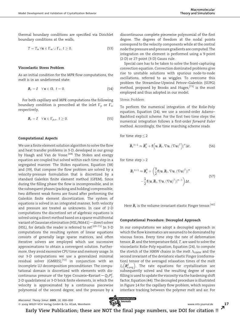
To perform the numerical integration of the Rolie-Poly
equation, Equation (24), we use a second-order Adams–
Bashford explicit scheme. For the first two time steps the
numerical integration follows a first-order forward Euler
method. Accordingly, the time marching scheme reads
for time step� 2
fin
Benþ1 B
ne þ f u;Be;ru; ruð ÞT
� �jnDt; (56)
for time step> 2
Benþ1 B
ne þ
�3
2fðu;Be;ru; ðruÞTÞjn
� 1
2fðu;Be;ru; ðruÞTÞjn�1
�Dt:
(57)
Here Be is the volume-invariant elastic Finger tensor.[42]
Computational Procedure: Decoupled Approach
In our computations we adopt a decoupled approach in
which theflowkinematics are assumed tobedominatedby
viscous forces. Every time step the rate of deformation
tensor,D, and the temperature field, T, are used to solve the
viscoelastic Rolie-Poly equation, Equation (24), to compute
the stretch of the HMW chains in the melt LHMW and the
second invariant of the deviatoric elastic Finger (conforma-
tion) tensor of the averaged relaxation times of the melt
J2 Bde;avg
� �. The rate equations for crystallization are
subsequently solved and the resulting degree of space
filling is used toupdate the viscosity via thehardening shift
factor, Equation (44). The decoupled procedure is illustrated
in Figure 14 for the capillary flow problem, which requires
interface tracking between the polymer melt and air. For
www.mts-journal.de 17
al page numbers, use DOI for citation !! R

F. J. M. F. Custodio, R. J. A. Steenbakkers, P. D. Anderson, G. W. M. Peters, H. E. H. Meijer
Table 8. Computed Weissenberg numbers based on disengage-ment (Wid) and Rouse (WiR) times, for the highest relaxationmode.
Conditions Wid [–] WiR [–]
MPR1 7.4� 104 4.4� 103
MPR2 6.7� 104 4.0� 103
MPR3 3.5� 104 2.1� 103
MPR4 0.8� 104 0.5� 103
Figure 14. Decoupled computational procedure: the kinematics ofa viscous flow problem are used to solve a coupled stress-crystal-lization problem. The computed degree of space filling is used toupdate the viscosity.
18
REa
theMPR case the problem is simpler, since no interface has
to be tracked.
Modeling Results and Discussions
Multipass Rheometer (MPR)
Themicrographsofmicrotomed injectionmoldingsamples,
as the ones shown in Figure 7 for the MPR experiments,
denote in many cases sharp transitions between morpho-
logical layers, i.e., oriented layer, fine-grained layer, and
spherulitical core. The transitions between these layers
maybe expected to be related to critical values of themodel
parameters thatdriveflow-inducednucleationandgrowth,
LHMW and J2�Bde;avg
�, respectively, and the predicted
morphological parameters. Hence, we first look at the
evolution of these parameters at the transition from the
oriented shear layer to the fine-grained layer for flow
conditions MPR1 and MPR2, whose optical micrographs
clearlyexhibitanorientedshear layer, seeFigure7.Thetime
scale of the flow analysis is limited to the influence of flow
on crystallization, which is determined by the relaxation of
J2�Bde;avgÞ, since the flow-induced nucleation rate _Nf , given
by Equation (11), becomes zero when the flow is stopped.
After an elapsed time of t¼ 1.5 s, J2�Bde;avgÞ becomes ofO (1)
at the slit walls for conditions MPR1 and MPR2, thus the
time scale of theflowanalysis is limited to 1.5 s, afterwhich
the wall temperature is set to room temperature T¼ 238C.Thecrystallizationkineticsarecalculateduntil thedegreeof
space filling jg is 1 everywhere. To better compare all the
flowconditions,we list inTable8 theWeissenbergnumbers
Macromol. Theory Simul. 2009, 18, 000–000
� 2009 WILEY-VCH Verlag GmbH & Co. KGaA, Weinheim
rly View Publication; these are NOT the fina
of each condition, based on the disengagement and Rouse
times of the longest molecules, with Wid;R ¼ _gwalltd;R.
In Figure 15(a) we plot the time evolution of the
molecular stretch (LHMW) at the positions of the transition
betweentheorientedshear layerand thefine-grained layer.
Once the critical stretch,Lcrit¼ 40, is reached the transition
from regime I to regime II, see Figure 1, takes place, and
shish start to growat a rate, according to Equation (13), that
is dependent on J2�Bde;avgÞ, see Figure 15(c). The critical
stretch is reached first for condition MPR1 at t 0.08 s,
which is expected based on the higher Weissenberg
numbers Wid,R for this condition, see Table 8. The final
values of the molecular stretch computed for both
conditions are remarkably close to each other (for
MPR1 90 and for MPR2 70). After cessation of flow,
the stretch does not relax on the time scale of the
simulations, due to the coupling of the Rouse time with
the number of flow-induced nuclei. The time evolution of
the total number of real flow-induced nuclei Nf,real at the
transition between the oriented shear layer and fine-
grained layer, calculated from Equation (22), is shown in
Figure 15(b).Nf,real is found to be very similar between both
conditions, just slightly lower for condition MPR2. The
number density remains constant after cessation of flow
dueto the function d inEquation (11). Figure15(d) showsthe
timeevolutionof the total real shish lengthperunit volume
Ltot,real, calculated from Equation (23). Ltot,real is found to
be approximately three times higher for condition MPR1
than for flow conditionMPR2, in agreementwith the larger
area underneath the curve in Figure 15(c). The values of
LHMW, Nf,real and Ltot,real for flow conditions MPR1 and
MPR2, at the transition between the oriented shear layer
and the fine-grained layer are listed in Table 9. The values
are of the same order of magnitude for the two flow
conditions. Based on the crystalline morphology shown by
the optical micrographs, see Figure 7, one can expect the
transition from the spherulitical core to the fine-grained
layer to be defined by a characteristic total number of flow-
induced nuclei Nf,fg. Likewise, the transition from the fine-
grained layer to the oriented shear layer should be
identified by the properties of the shish, either by a critical
average shish length hLicrit, or, more likely, a critical total
DOI: 10.1002/mats.200900016
l page numbers, use DOI for citation !!

Model Development and Validation of Crystallization Behavior
Figure 15. Model results for flow conditions MPR1 and MPR2, at the position of thetransition from the oriented shear layer to the fine-grained layer obtained from theoptical micrographs Figure 7: (a) molecular stretch LHMW; (b) time evolution of the totalnumber of flow-induced nuclei per unit volume; (c) evolution of the second invariant ofthe deviatoric elastic Finger tensor of the averaged relaxation mode J2
�Bde;avgÞ; (d) time
evolution of the total shish length per unit volume Ltot,real.
Table 9. Model parameters at the transition between theoriented and the fine-grained layers.
Conditions LHMW [–] Nf,real [–] Ltot,real
m�2
MPR1 90 1012 0.9� 109
MPR2 70 0.77� 1012 0.3� 109
shish length per unit volume Ltot,crit, upon which an
oriented crystalline morphology becomes noticeable at a
micro scale. Therefore, we postulate that within the fine-
grained layer either the kinetics of flow-induced crystal-
lization take placewithin regime I, see Figure 1, and, in that
case, only an increase in number of spherulitical structures
occurs, or the growth rate of shish is too slow or takes place
within too short aperiodof time, so the shish stay relatively
short. Regarding the shear oriented layer, we expect flow to
induce only fibrillar nucleation (regime II).
We proceed comparing themodel predictions in terms of
Ltot,real, Nf,real, and hLi at the transitions between the
different morphological layers for all flow conditions, after
no further morphological changes take place. The average
length of shish-kebabs hLi can be calculated dividing the
Macromol. Theory Simul. 2009, 18, 000–000
� 2009 WILEY-VCH Verlag GmbH & Co. KGaA, Weinheim
Early View Publication; these are NOT the final page n
total shish length by the total number of
flow-induced nuclei per unit volume:
umb
hLi ¼ Ltot;realNf;real
: (58)
In Figure 16we plot Ltot,real,Nf,real, and
hLi over half of the normalized slit
thickness, for flow conditions MPR1
and MPR2. The values predicted for
condition MPR1 of Ltot,real, Nf,real, and
hLi at the transition of the shear oriented
layer, are tested if they can be used as
critical values that have to be surpassed
for an oriented layer to become visible,
see Figure 16. Ltot,crit denotes the critical
value of Ltot,real, hLicrit the critical averageshish length,Nf,ori andNf,fg the values of
Nf,real found at the transition of the
orientedshear layerandat the transition
of the fine-grained layer to the spheru-
litic core, respectively. To assess the
predictive capability of the model, the
values Ltot,crit, hLicrit,Nf,ori, andNf,fg, taken
from condition MPR1, are used as
morphological criteria for the other flow
conditions. The value predicted for a
critical shish length hLicrit is around
1mm, which obviously is not realistic,
making the comparison qualitative only and indicating
that a further calibration of the model parameters is
required. Typical shish lengthsare thought tobe in theorder
ofmicrons. Thecomputed Ltot,real and hLi for conditionMPR1
lie within the flow-induced crystallization region (did not
cross the fine-grained layer to the spherulitical core),
implying that the critical stretch Lcrit was reached only
within this region. In the plots corresponding to condition
MPR2 the open circles denote the critical values computed
for condition MPR1. The circles fall almost on top of the
curves, indicating that the different morphological criteria
agreebetween these twoconditions.However, the criterion
based on total shish length Ltot,real, seems to be in better
agreement between the conditions than the one based on
the average shish length hLi. The total number of flow-
inducednucleiNf,real at the transitionbetween thedifferent
layers is also in good agreement between both conditions.
Also for condition MPR2 the critical stretch, required for
oriented crystals to grow (regime II), was reached only
within the observed flow-induced crystallization region.
Next, the flow conditions under which no oriented shear
layerdeveloped,namelyMPR3andMPR4, are considered. In
Figure 17we plot Ltot,real,Nf,real, and hLi for conditionsMPR3
and MPR4. The number of flow-induced nuclei at the
transition between the fine-grained layer and spherulitical
www.mts-journal.de 19
ers, use DOI for citation !! R

F. J. M. F. Custodio, R. J. A. Steenbakkers, P. D. Anderson, G. W. M. Peters, H. E. H. Meijer
Figure 16. Distribution across half of the normalized slit thickness of the total shishlength Ltot,real, the number of flow-induced nuclei per unit volume Nf,real, and the averageshish length hLi, after correcting for impingement, for flow conditions MPR1 and MPR2.
20
REa
corepredicted for conditionsMPR3andMPR4 ishigher than
the one predicted for condition MPR1 (open circles). The
value predicted at the transition to the oriented shear layer
Nf,ori for condition MPR1 is also given as a reference at the
wall, since there no oriented layer developed from
conditions MPR3 and MPR4. For both conditions, however,
Nf,real exceeds Nf,ori from MPR1. The computed values for
Ltot,real and hLi are everywhere across the thickness smaller
than Ltot,crit and hLicrit, respectively, with the exception of
Macromol. Theory Simul. 2009, 18, 000–000
� 2009 WILEY-VCH Verlag GmbH & Co. KGaA, Weinheim
rly View Publication; these are NOT the final page numbe
Ltot,real for condition MPR3 which equals
Ltot,crit at the wall. Such results are
obviously important, since they imply
that a critical, total or average, shish
length, required for an observable
oriented shear layer, was not reached.
However, the computed local shish
length, Ltot,real and hLi for condition
MPR3, went beyond the flow-induced
crystallization region, implying that the
critical stretch Lcrit was reached within
the spherulitical core. This suggests that
shish-kebabsmightdevelop in the spher-
ulitical region, however their length or
volume fraction is too small.
Notice that these analyses, based on a
coarsecharacterizationdonebymeansof
optical light microscopy, can only be
aimed at qualitative agreements. The
definitionofacritical shish lengthshould
therefore be based on a more resolved
analysis based on techniques that allow
to assess more detailed morphological
information, such as small angle X-ray
scattering (SAXS).
Oriented Volume-Based Criterion
As it was suggested in ref.[74] the
relative volume of oriented crystalline
material, shish-kebabs volume over
the total crystalline volume, could also
be used as a criterion to define the
transition between the oriented shear
layer and the fine-grained layer. In
Figure 18(a–d) we plot the relative
undisturbed volume fraction of oriented
crystals, Vori, defined as c0/(f0þc0),
after the completion of the crystalliza-
tion process (after cooling to room
temperature). The value of Vori com-
puted at the transition from the
oriented shear layer to the fine-grained
layer in conditions MPR1 and MPR2 is
almost the same (0.026). Again, this
value seems to be rather low and further
calibration of the model parameters is required. For flow
conditions MPR3 and MPR4, Vori is everywhere across the
sample thickness smaller than the critical value Vori,crit
defined from flow condition MPR1, see Figure 18(a). This is
in agreement with the experimental results that no visible
oriented shear layer developed under flow conditions
MPR3 and MPR4. Comparing conditions MPR1 and MPR2,
the values of Vori computed toward the slit wall for
condition MPR2 are higher. To understand this we plot in
DOI: 10.1002/mats.200900016
rs, use DOI for citation !!

Model Development and Validation of Crystallization Behavior
Figure 17. Distribution across half of the normalized slit thickness of the total shishlength Ltot,real, the number of flow-induced nuclei per unit volume Nf,real, and theaverage shish length hLi, after correcting for impingement, for flow conditions MPR3and MPR4.
Figure 19(a) and (b) the time evolution of the total shish-
kebab and spherulitical volume close to the wall, where
the highest volume fraction of oriented crystals is
computed. As expected, the volume of shish-kebabs is
higher for condition MPR2. Contributing to this, is the
larger computed value for Ltot,real, see Figure 16, and the
radial growth of kebabs. The predicted spherulitical
volume for condition MPR2 is also found to be smaller
Macromol. Theory Simul. 2009, 18, 000–000
� 2009 WILEY-VCH Verlag GmbH & Co. KGaA, Weinheim
Early View Publication; these are NOT the final page n
then condition MPR1, further favoring a
higher volume fraction of oriented
crystals. The time evolution of the radial
growth rate G(T, p), given by Equation
(27), at the same position close to the
wall after wall quenching is shown in
Figure 20(a) for conditions MPR1 and
MPR2. One can clearly see that the radial
growth for condition MPR1, due to
differences in cooling history, see
Figure 20(b), is higher, explaining the
larger spherulitical volume predicted for
this condition.
Capillary Rheometer
For the capillary rheometer the coupling
of the viscosity with the degree of space
filling gave rise to a non-smooth stress
field. To circumvent this numerical pro-
blem, which originated from a non-
smooth viscosity distribution from the
wall to the core, we did not couple the
viscosity with the degree of space filling,
Equation (43), with the consequence of
reducing the effect of flow on crystal-
lization. Figure 21 shows the computed
total shish length per unit volume Ltot,real,
the total number of flow-induced nuclei
Nf,real and the local average shish length
hLi, across the thickness of the slit at
position 2, see Figure 6, for the capillary
experimental flow conditions. The corre-
spondingmicrographs are givenon topof
the figure.
To verify the validity of morphological
criteria based on shish length within the
capillary experiments, the values of
Ltot,real and hLi computed from CA3 at
the transition of the oriented shear layer
to the spherulitical core are taken as
criteria for conditions CA1 andCA2 (black
dots). It can be seen that the dots fall on
top of the curves, thus indicating that the
model predicts at the transition of the
oriented layer similar values for Ltot,real and hLi, for
completely different filling conditions. The open circles
denote the critical values computed from condition MPR1.
The values for Ltot,real computed at the transition to the
oriented layer are close to Ltot,crit obtained from MPR1.
However, the predicted values for hLi for flow conditions
CA1, CA2, andCA3are 3orders ofmagnitude lower than the
predicted value for the MPR experiments, which is mainly
www.mts-journal.de 21
umbers, use DOI for citation !! R

F. J. M. F. Custodio, R. J. A. Steenbakkers, P. D. Anderson, G. W. M. Peters, H. E. H. Meijer
Figure 18. Distribution of the relative volume of oriented material, Vori¼c0/(f0þc0),across half of the normalized slit thickness: (a) flow condition MPR1; (b) flow conditionMPR2; (c) flow condition MPR3; and (d) flow condition MPR4.
Figure 19. (a) Time evolution of the undisturbed shish volume c0, close to the slit wall,for flow conditions MPR1 and MPR2; (b) time evolution of the undisturbed spheruliticalvolume f0, close to the slit wall, for flow conditions MPR1 and MPR2.
Figure 20. (a) Time evolution of the spherulitical growth rate G(T, p), close to the slit wall,for flow conditions MPR1 and MPR2; (b) time evolution of the temperature T afterquench, for flow conditions MPR1 and MPR2.
22Macromol. Theory Simul. 2009, 18, 000–000
� 2009 WILEY-VCH Verlag GmbH & Co. KGaA, Weinheim
REarly View Publication; these are NOT the final page numb
due to the higher predicted critical
number of flow-induced nuclei Nf,ori (2–
3 orders higher). The criterion based on
the total shish length per unit volume
Ltot,crit is the one that gives the best
agreement between the different experi-
mental setups. It suggests that it is the
total shish length per unit volume that
determines the visibility of an oriented
layer, and not the actual local shish
length. The non-isothermal flow condi-
tions under which the capillary experi-
ments take place might explain the
morphological differences. Nevertheless
the model seems to give consistent
resultswithineachseriesof experiments,
i.e., the average shish length criterion is
valid within the MPR and the capillary
rheometer experiments, and a reason-
ablygoodagreement in termsof Ltot,real. It
is also interesting that the model cap-
tures the transition layer between the
skin and shear layers. For all the condi-
tions, almost everywhere in this region
the critical stretch of the long chains
LHMW, which has to be surpassed for
oriented crystals to grow (regime II), was
not reached. It can be seen in Figure 21
thatno shish-kebabsarepredicted in that
region by themodel. This means that the
couplingbetweenthefast coolingclose to
the wall, and the transient viscoelastic
behavior is captured quite well.
Oriented Volume-Based Criterion
The computed volume fraction of
oriented crystals at the transition to the
oriented shear layer for the experimental
condition MPR1 (Vori¼ 0.026), was
defined as a criterion Vori,crit to identify
the transition to the oriented shear layer.
We now test the validity of this criterion
in the capillary rheometer experimental
results.
In Figure 22(a–c) we plot the volume
fraction of oriented crystals for capillary
conditions CA1, CA2, and CA3, respec-
tively. The critical value Vori,crit, taken
from the conditionMPR1, is plotted as an
open circle. For all flow conditions the
predicted volume fraction of oriented
crystals at the transition to the shear
layer is remarkably similar, and the
values are very close to the critical value
DOI: 10.1002/mats.200900016
ers, use DOI for citation !!

Model Development and Validation of Crystallization Behavior
Figure 21. Distribution across half of the normalized slit thickness of the total shish length Ltot,real, the number of flow-induced nuclei perunit volume Nf,real, and the average shish length hLi, after correcting for impingement, for flow conditions CA1, CA2, and CA3, at slitposition 2.
Figure 22. Distribution across half of the normalized slit thickness of the relative volumeof oriented material, Vori¼c0/(f0þc0), at slit position 2: (a) flow condition CA1, (b) flowcondition CA2, and (c) flow condition CA3.
Macromol. Theory Simul. 2009, 18, 000–000
� 2009 WILEY-VCH Verlag GmbH & Co. KGaA, Weinheim
Early View Publication; these are NOT the final page n
Vori,crit. For conditions CA2 and CA3 the
agreement isexcellent;Vori,crit falls on top
of the computed curves. This strongly
indicates that the criterion based on
Vori,crit holds for experiments conducted
under quasi-isothermal (MPR) and non-
isothermal (capillary rheometer) condi-
tions.
Due to start-up effects, which become
more noticeable at high piston speeds
(short flow times), the calculated average
velocity in the slit for condition CA1, see
Table 6, is overestimated. This could
explain the lower predicted thickness of
the oriented shear layer for this condi-
tion.
Based on the excellent agreement
found for conditions CA2 and CA3, we
plot for these conditions in Figure 23(a)
and (b) the predicted and measured
thickness of the oriented region at
different positions along the slit. The
predicted thickness of the oriented layer
is close to the measured values and
www.mts-journal.de 23
umbers, use DOI for citation !! R

F. J. M. F. Custodio, R. J. A. Steenbakkers, P. D. Anderson, G. W. M. Peters, H. E. H. Meijer
Figure 23. Symbols: measured and predicted oriented crystalline region thickness, basedon the critical volume fraction of oriented crystals criterion Vori,crit, for capillary flowcondition (a) CA2 and (b) CA3. Lines are shown to guide the eye.
24
REa
agrees well with the experimental trends: the thickness of
the oriented crystalline region is higher at the center
(position 2) of the slit.
Conclusion
In conclusion, we present in this study a model to predict
the resulting morphology of semi-crystalline polymers
when processed via injection molding prototype flows. A
model within the framework of molecular-based rheologi-
cal modeling is proposed, in which quiescent and flow-
enhanced crystallization processes are coupled to the flow
history, and the deformation of long chains is assumed to
driveflow-enhancednucleation.Themodel is testedonaset
of experimental results obtained using special experimen-
tal devices inwhich theprocessinghistory, i.e., deformation
and thermal history, is accurately controlled. The approach
adopted in this study aimed at, first of all, predicting flow-
induced crystalline morphologies created under quasi-
isothermal conditions (MPR) and then under non-isother-
mal conditions (capillary rheometer) that mimic injection
molding conditions. The model predictions in terms of
number, size and shape of crystalline structures for both
non-oriented and oriented crystals, allows to establish
criteria in terms of total shish length per unit volume
Ltot,real, average shish length hLi and volume fraction of
oriented crystals Vori, to identify the onset of an oriented
shear layer. Such criteria are found to be in reasonably good
agreement within the different experimental setups,
between the tested flow conditions. Also, the predicted
number of flow-induced nuclei at the transition of the
morphological layers is found to be in agreement between
all flow-conditions, within the MPR and capillary experi-
ments. However, it is important to stress, based on the
model results, that criteria defined by hLicrit do not hold
between isothermalandnon-isothermalflowconditions. In
contrast, criteria based on Ltot,real and Vori seem to give a
Macromol. Theory Simul. 2009, 18, 000–000
� 2009 WILEY-VCH Verlag GmbH & Co. KGaA, Weinheim
rly View Publication; these are NOT the final page numb
quantitative agreement between all
experiments, i.e., quasi- and non-isother-
mal flow conditions, in terms of a critical
value for the transitions. We cannot
make a quantitative comparison
between measured and computed mor-
phological measures due to lack of
experimental data and, therefore, can
also not tune our model parameters.
However, themorphological information
predicted by the model is essential to
construct the material microstructure,
which could be embedded in a multi-
scale modeling framework, as proposed
in ref.[75] to relate morphology to proper-
ties. Such approaches employ represen-
tative volume elements (RVEs) of the microstructure to
predict the macroscopic mechanical response, thus using
the microscale information to build an engineering-scale
material model.
Summarizing,wefindthepresent results encouraging, in
that a unified model for quiescent and flow-induced
crystallization can be developed, sensitive to themolecular
weigh of the material, with few fitting parameters and
generalized to other materials.
Practical Aspects of Crystallization Modeling
The application of elaborate models to predict the
morphology of semi-crystalline materials, as the one
presented in this study, in commercial software is still
restricted by reasons of economical and practical nature.
The main difficulty originates from the extensive material
characterization required. A complete rheological charac-
terization of the material is needed to determine the
spectrum of relaxation times. Additionally, the character-
izationofquiescent crystallizationkineticshas tobedone in
experiments in which spherulites are counted under an
optical microscope for different thermal and pressure
histories. Furthermore, the approach suggested here to
assess flow-induced crystallization kinetics combines the
use of rheometry with numerical modeling, in which
changes measured in the elastic modulus G0 during
crystallization, are predicted and used to fit the model
parameters gn and gl. Last but not least, saturation studies
also have to be done to determine the saturation level of
flow-induced crystallization, which involve a shear flow
device, e.g., Linkam shear cell, and optical microscopy.
Hence, as theunderstandingofflow-inducedcrystallization
phenomena improves, more material data are required to
feed rheological and kinetic models.
From a numerical point of view, the model presented
here also puts some demands on currently available
DOI: 10.1002/mats.200900016
ers, use DOI for citation !!

Model Development and Validation of Crystallization Behavior
software, as it requires two additional coupled problems to
be solved: a two-mode viscoelastic stress problem, and a
crystallization problem. The spatial discretization of the
domainhas tobe sufficiently resolved to compute a smooth
viscoelastic stress field and, consequently, the crystalline
morphology. Using explicit integration schemes to com-
pute viscoelastic stresses, as the one adopted here, time
steps become limited by the viscoelastic stress problem.
Hence, computation times are significantly increased.
Acknowledgements: This work was funded by the PortugueseFoundation for Science and Technology (FCT), under the PhD grantSFRH/BD/16544/2004 /C3MW.
Received: March 23, 2009; Revised: July 10, 2009; DOI: 10.1002/mats.200900016
Keywords: crystallization; flow-induced nucleation; injectionmolding; morphology; polypropylene (PP); shish-kebabs
[1] J.-W. Housmans, L. Balzano, D. Santoro, G. Peters, H. Meijer,Int. Polym. Proc. 2009, 24, 185.
[2] J.-W. Housmans, M. Gahleitner, G. Peters, H. Meijer, Polymer2009, 50, 2304.
[3] G. Eder, H. Janeschitz-Kriegl, Materials Science and Technol-ogy, Vol. 18, H. Meijer, Ed., VCH, Verlagsgesellschaft mbH,Weinheim 1997, Ch. 5.
[4] M. Fujiyama, T. Wakino, J. Appl. Polym. Sci. 1988, 35, 29.[5] B. Schrauwen, L. van Breemen, A. Spoelstra, L. Govaert, G.
Peters, H. Meijer, Macromolecules 2004, 37, 8618.[6] J. Viana, A. Cunha, N. Billon, Polymer 2002, 43, 4185.[7] R. Pantani, I. Coccorullo, V. Speranza, G. Titomanlio, Prog.
Polym. Sci. 2005, 30, 1185.[8] A. Kolmogorov, Isvest. Akad. Nauk. SSSR Ser. Math. 1937, 1,
355.[9] M. Avrami, J. Chem. Phys. 1939, 7, 1103.[10] M. Avrami, J. Chem. Phys. 1940, 8, 212.[11] J. Hoffman, J. Lauritzen, J. Res. Natl. Bur. Stand. 1961, 65, 297.[12] J. Smirnova, L. Silva, B. Monasse, J.-L. Chenot, J.-M. Haudin, Int.
Polym. Proc. 2005, 20, 178.[13] R. Pantani, I. Coccorullo, V. Speranza, G. Titomanlio, Polymer
2007, 48, 2778.[14] K. Watanabe, T. Susuki, T. Masubuchi, T. Taniguchi, J.-I.
Takimoto, K. Koyama, Polymer 2003, 44, 5843.[15] M. van der Beek, G. Peters, H. Meijer, Macromol. Mater. Eng.
2005, 290, 443.[16] M. van der Beek, Specific volume of polymers. Influence of
thermomechanical history, PhD thesis, Eindhoven Universityof Technology, Eindhoven, The Netherlands, 2005.
[17] K. Nakamura, T. Watanabe, K. Katayama, T. Amano, J. Appl.Polym. Sci. 1972, 16, 1077.
[18] C. Hieber, Polym. Eng. Sci. 2002, 42, 1387.[19] R. Patel, J. Bheda, J. Spruiell, J. Appl. Polym. Sci. 1991, 42, 1671.[20] A. Isayev, T. Chan, K. Shimojo, M. Gmerek, J. Appl. Polym. Sci.
1995, 55, 807.
Macromol. Theory Simul. 2009, 18, 000–000
� 2009 WILEY-VCH Verlag GmbH & Co. KGaA, Weinheim
Early View Publication; these are NOT the
[21] A. Isayev, T. Chan, M. Gmerek, K. Shimojo, J. Appl. Polym. Sci.1995, 55, 821.
[22] G. Eder, H. Janeschitz-Kriegl, S. Liedauer, Progr. Polym. Sci.1990, 15, 629.
[23] S. Liedauer, G. Eder, H. Janeschitz-Kriegl, P. Jerschow, W.Geymayer, E. Ingolic, Int. Polym. Proc. 1993, 8, 236.
[24] A. Isayev, B. Catignani, Polym. Eng. Sci. 1997, 37, 1526.[25] X. Guo, A. Isayev, M. Demiray, Polym. Eng. Sci. 1999, 39, 2132.[26] A. Isayev, Y. Churdpunt, X. Guo, Int. Polym. Proc. 2000, 15, 72.[27] K. Kim, A. Isayev, K. Kwon, J. Appl. Polym. Sci. 2005, 95, 502.[28] P. Flory, J. Chem. Phys. 1947, 15, 397.[29] G. Titomanlio, G. Lamberti, Rheol. Acta 2004, 43, 146.[30] S. Kimata, T. Sakurai, Y. Nozue, T. Kasahara, N. Yamaguchi, T.
Karino, M. Shibayama, J. Kornfield, Science 2007, 316, 1014.[31] R. Somani, L. Yang, L. Zhu, B. Hsiao, Polymer 2005, 46, 8587.[32] G. Kumaraswamy, J. Macromol. Sci., Part A: Polym. Rev. 2005,
45, 375.[33] S. Vleeshouwers, H. Meijer, Rheol. Acta 1996, 35, 391.[34] P. Jerschow, H. Janeschitz-Kriegl, Int. Polym. Proc. 1997, 22, 72.[35] M. Seki, D. Thurman, J. Oberhauser, J. Kornfield, Macromol-
ecules 2002, 35, 2583.[36] R. Somani, L. Yang, B. Hsiao, H. Fruitwala, J. Macromol. Sci.,
Part B: Phys. 2003, 42, 515.[37] S. Liedauer, G. Eder, H. Janeschitz-Kriegl, Int. Polym. Proc.
1995, 10, 243.[38] P. Jerschow, H. Janeschitz-Kriegl, Rheol. Acta 1996, 35, 127.[39] G. Kumaraswamy, R. Verma, A. Issaian, P. Wang, J. Kornfield,
F. Yeh, B. Hsiao, R. Olley, Polymer 2000, 41, 8931.[40] A. Keller, H. Kolnaar, Materials Science and Technology,
Vol. 18, H. Meijer, Ed., VCH, Verlagsgesellschaft mbH, Wein-heim 1997, Ch. 4.
[41] J. Van Meerveld, G. Peters, M. Hutter, Rheol. Acta 2004, 44,119.
[42] H. Zuidema, G. Peters, H. Meijer, Macromol. Theory Simul.2001, 10, 447.
[43] F. Azzurri, G. Alfonso, Macromolecules 2005, 38, 1723.[44] R. Steenbakkers, G. Peters, The XVth International Congress on
Rheology, Monterey, California, USA, 2009.[45] J.-W. Housmans, R. Steenbakkers, P. Roozemond, G. Peters, H.
Meijer, Macromolecules 2009, in print.[46] O. Mykhaylyk, P. Chambon, R. Graham, P. Fairclough, P.
Olmsted, A. Ryan, Macromolecules 2008, 41, 1901.[47] R. Graham, P. Olmsted, Faraday Disc. 2009, accepted.[48] R. Graham, A. Likhtman, T. McLeish, S. Milner, J. Rheol. 2003,
47, 1171.[49] J. Martins, W. Zhang, A. Brito,Macromolecules 2006, 39, 7626.[50] D. Hristova, G. Peters, Personal Commun. 2009.[51] A. Likhtman, R. Graham, J. Non-Newtonian Fluid Mech. 2003,
114, 1.[52] J. Vega, D. Hristova, G. Peters, J. Therm. Anal. Calorim. 2009,
accepted.[53] G. Lamberti, C. Naddeo, Polym. Bull. 2006, 56, 591.[54] F. de Santis, G. Lamberti, G. Peters, V. Brucato, Eur. Polym. J.
2005, 41, 2297.[55] R. Steenbakkers, G. Peters, H. Meijer, The 24th AnnualMeeting
of the Polymer Processing Society, Salerno, Italy, 2008.[56] R. Steenbakkers, G. Peters, Rheol. Acta 2008, 47, 643.[57] C. Macosko, Rheology: Principles, Measurements, and Appli-
cations, Wiley-VCH, New York 1994.[58] M. Doi, S. Edwards, The theory of Polymer Dynamics, Oxford
University Press, Oxford 1986.[59] M. Mackley, R. Marshall, J. Smeulders, J. Rheol. 1995, 39, 1293.[60] A. Kech, H.-C. Ludwig, B. Moginger, P. Eyerer, J. de Claville
Cristiansen, Int. Polym. Proc. 2000, 15, 202.
www.mts-journal.de 25
final page numbers, use DOI for citation !! R

F. J. M. F. Custodio, R. J. A. Steenbakkers, P. D. Anderson, G. W. M. Peters, H. E. H. Meijer
26
REa
[61] G. Kalay, R. Sousa, R. Reis, A. Cunha, M. Bevis, J. Appl. Polym.Sci. 1999, 73, 2473.
[62] G. Lamberti, G. Peters, G. Titomanlio, Int. Polym. Proc. 2007,22, 303.
[63] W. Hwang, M. Hulsen, H. Meijer, J. Non-Newtonian FluidMech. 2004, 121, 15.
[64] W. Hwang,M. Hulsen, H.Meijer, T. Kwon,XIVth InternationalCongress on Rheology, Seoul, Republic of Korea, 2004,pp. CR10–1–CR10–3.
[65] G. d’Avino, P. L. Maffettone, M. Hulsen, G. Peters, J. Non-Newtonian Fluid Mech. 2008, 150, 65.
[66] R. Christensen, J. Mech. Phys. Solids 1990, 38, 379.[67] E. Thompson, Int. J. Numer. Methods Fluids 1986, 6, 749.
Macromol. Theory Simul. 2009, 18, 000–000
� 2009 WILEY-VCH Verlag GmbH & Co. KGaA, Weinheim
rly View Publication; these are NOT the fina
[68] G. Haagh, F. Van de Vosse, Int. J. Numer. Methods Fluids 1998,28, 1355.
[69] P. Amestoy, I. Duff, Int. J. Supercomput. Appl. 1989, 7, 64.[70] P. Amestoy, I. Duff, Int. J. Supercomput. Appl. 1989, 3, 41.[71] P. Amestoy, C. Puglisi, SIAM. J. Matrix Anal. Appl. 2002, 24, 553.[72] Y. Saad, M. Schultz, SIAM, J. Matrix Anal. 1992, 121.[73] A. Brooks, T. Huges, Comput. Methods Appl. Mech. Eng. 1982,
32, 199.[74] H. Zuidema, Flow induced crystallization of polymers, PhD
thesis, Eindhoven University of Technology, Eindhoven, TheNetherlands, 2000.
[75] J. van Dommelen, D. Parks, M. Boyce, W. Brekelmans,F. Baaijens, Polymer 2003, 44, 6089.
DOI: 10.1002/mats.200900016
l page numbers, use DOI for citation !!