Embed Size (px)
Citation preview
750-38212/2019
Model CBTTubeless Vertical
Steam BoilerOperation and Maintenance Manual
ii
Should overheating occur or the gas supply valve fail to shut off, do not turn off or disconnect the electrical sup-ply to the boiler. Instead turn off the gas supply at a lo-cation external to the boiler.
! DANGERWARNING
! DANGERWARNINGIf the information in this manual is not followed exactly, a fire or explosion may result causing property dam-age, personal injury or loss of life.
— Do not store or use gasoline or other flammable va-pors and liquids in the vicinity of this or any other appli-ance.
— WHAT TO DO IF YOU SMELL GAS• Do not try to light any appliance.• Do not touch any electrical switch; do not use
any phone in your building.• Immediately call your gas supplier from a
neighbor's phone. Follow the gas supplier's instructions.
• If you cannot reach your gas supplier, call the fire department.
— Installation and service must be performed by a qualified Cleaver-Brooks, service agency or the gas supplier.
Improper installation, adjustment, service, or mainte-nance can cause equipment damage, personal injury, or death. Refer to the Operation and Maintenance manual provided with the boiler. Installation and ser-vice must be performed by a qualified Cleaver-Brooks service provider.
! DANGERWARNING
! DANGERWARNING
Be sure the fuel supply which the boiler was designed to operate on is the same type as specified on the boiler name plate.
! DANGERWARNING
Do not use this boiler if any part has been under water. Immediately call your Cleaver-Brooks ser-vice representative to inspect the boiler and to re-place any part of the control system and any gas control which has been under water.
! DANGERWARNINGTo minimize the possibility of serious personal injury, fire or damage to the equipment, never violate the fol-lowing safety rules. — Always keep the area around the boiler free of com-bustible materials, gasoline, and other flammable liq-uids and vapors— Never cover the boiler, lean anything against it, stand on it, or in any way block the flow of fresh air to the boiler.
This manual must be maintained in legible condi-tion and kept adjacent to the boiler or in a safe place for future reference. Contact your local Cleaver-Brooks representative if additional manu-als are required.
Notice
Where required by the authority having jurisdiction, the installation must conform to the Standard for Controls and Safety Devices for Automatically Fired Boilers, ANSI/ASME CSD-1.
Notice
The boiler and its individual shutoff valve must be disconnected from the gas supply piping system during any pressure testing of that system at test pressures in excess of 1/2 psi (3.5 kPa).
! DANGERWARNING The installation must conform to the requirements of the authority having jurisdiction or, in the ab-sence of such requirements, to UL 795 Commer-cial-Industrial Gas Heating Equipment and/or the National Fuel Gas Code, ANSI Z223.1
! DANGERWARNING

CLEAVER-BROOKS
Model CBTTubeless Vertical Boiler
Operation, Service, and Parts Manual
Cleaver-Brooks 2019
Manual Part No. 750-382
12/2019
iii

Cleaver-Brooks equipment is designed and engineered for long life and excellent service. The electrical and mechanical devices supplied as part of the unit were chosen because of their known ability to perform; however, proper operating techniques and maintenance procedures must be followed at all times. Although these components afford a high degree of protection and safety, due attention must be given to the dangers and hazards inherent in handling and firing of fuel.
“Automatic” design features, where present, do not relieve the attendant of responsibility. Such features merely eliminate certain repetitive chores, allowing more time for the proper upkeep of equipment.
Controls and safety devices may vary due to state, local, or other applicable codes.
It is recommended that a boiler room log or record be maintained. Recording of daily, weekly, monthly and yearly main-tenance activities and recording of any unusual operation will serve as a valuable guide to any necessary investigation. Most instances of major boiler damage are the result of operation with low water. We cannot emphasize too strongly the need for the operator to periodically check the low water controls and to follow good maintenance and testing practices. Cross-connecting piping to low water devices must be internally inspected periodically to guard against any stoppages which could obstruct the free flow of water to the low water devices.
The waterside condition of the pressure vessel is of extreme importance. Waterside surfaces should be inspected fre-quently to check for the presence of mud, sludge, scale or corrosion. It is essential to obtain the services of a qualified water treating company or a water consultant to recommend the proper boiler water treating practices.
The operation of this equipment must comply with all requirements or regulations of the insurance company and/or other authority having jurisdiction. In the event of any conflict or inconsistency between such requirements and the warnings or instructions contained herein, please contact Cleaver-Brooks before proceeding.
DO NOT OPERATE, SERVICE, OR REPAIR THIS EQUIPMENT UNLESS YOU FULLY UNDERSTAND ALL APPLI-CABLE SECTIONS OF THIS MANUAL.
DO NOT ALLOW OTHERS TO OPERATE, SERVICE, OR REPAIR THIS EQUIPMENT UNLESS THEY FULLY UN-DERSTAND ALL APPLICABLE SECTIONS OF THIS MANUAL.
FAILURE TO FOLLOW ALL APPLICABLE WARNINGS AND INSTRUCTIONS MAY RESULT IN SEVERE PERSONAL INJURY OR DEATH.
! DANGERWARNING
iv
v
CONTENTS
CHAPTER 1 INTRODUCTION 1-1Pressure vessel 1-2Burner 1-4Gas train 1-5Controls 1-6Component/connection locations 1-8Optional equipment 1-10
CHAPTER 2 INSTALLATION 2-1Lifting and moving the boiler 2-2Water treatment 2-2Boiler room 2-4Gas piping 2-5Boiler water-side connections 2-10Electrical connections 2-11Wiring diagrams 2-12
CHAPTER 3 FLUE AND COMBUSTION AIR VENTING 3-1Venting connections — general 3-2Flue venting 3-2Vent terminal location 3-2Horizontal through-wall venting, inside air (Category III) 3-5Horizontal through-wall direct venting 3-6Horizontal through-wall flue vent termination 3-7Vertical venting, inside combustion air (Category III) central heating 3-8Vertical venting, direct vent combustion air (Category III) 3-9Flue and combustion air duct design using direct vent combustion 3-9
CHAPTER 4 COMMISSIONING 4-1Commissioning 4-2Boil-out of a new unit 4-25Post start-up checkout procedure 4-26Falcon control functions and customer interface 4-26
CHAPTER 5 MAINTENANCE 5-1General 5-2Bottom blowdown 5-2Water column blowdown 5-3Fireside cleaning procedure/disassembly 5-5Ignition electrode 5-7UV scanner 5-7Waterside inspection/cleaning 5-9Safety valve 5-10Troubleshooting 5-10Display diagnostics 5-26Lay-up 5-26
CHAPTER 6 PARTS 6-1Recommended spare parts list 6-2Safety valves 6-2Control panel 6-3Burner assembly 6-5Water Column 6-13Gas train 6-14Direct vent kits 6-15
APPENDIX A — CB Falcon ControllerAPPENDIX B — Falcon Display/Operator InterfaceAPPENDIX C — Gas Valve

vi
CHAPTER 1 Introduction
Pressure vessel 1-2Burner 1-4Gas train 1-5Controls 1-6Component/connection locations 1-8Optional equipment 1-10
750-382CBT
1-1

Introduction
The Cleaver-Brooks Model CBT is a two-pass vertical tubeless steam boiler with side-mounted burner.
The CBT features thick pressure vessel plates designed to provide long life.
An ECM variable speed combustion air blower modulates the burner to precisely match steam production to demand for reduced fuel usage and cycling. The side-mount burner arrangement allows for a larger steam space to deliver excep-tionally dry steam quality while allowing easy access for service and mainte-nance. The Falcon control keeps the boiler and burner consistently operating at peak efficiency.
The CBT is available in 9.5, 10, 15, 20, 25, 30, 40, and 50 HP sizes. Features include:
• Natural gas and propane fuels• 15 psig or 150 psig design pressure• Up to 84% efficiency and high turndown with the PID modulating premix
burner.• Low emissions: less than 20 ppm NOx (full mod, natural gas only)• Robust pressure vessel, designed to provide long life; 5 year pressure vessel warranty• Standard integrated control with user-friendly interface for peak operation and efficiency
Quality construction
ASME construction ensures high quality design, safety, and reliability.
UL listed
The Model CBT and CBT-M are UL listed for both the US and Canada.
Premix technology
The Model CBT-M Boiler utilizes “Premix” technology to mix both fuel and combustion air prior to entering thefiring chamber. This technology provides clean, efficient combustion with very low emission levels.
1.1 — Pressure vessel
The boilers are constructed in accordance with the ASME Boiler Construction Code, Section I for high pressure steam boilers and Section IV for low pressure steam boilers. High pressure steam boilers are stamped with the ASME “S” symbol. Low pressure steam boilers are stamped with the ASME “H” symbol. The ASME data plate can be found on the lower portion of the vessel on the front or left side (see Figure 1-2).
The CBT is a vertically oriented 2-pass tubeless pressure vessel design with a water-backed furnace. The first fireside pass utilizes radiant heat transfer and the second pass uses convection. The second pass flue passage-ways incorporate extended heating surfaces designed using computational fluid dynamics (CFD) modeling.
The large steam chest volume ensures exceptional dry quality steam at both high and low operating pressures.
The pressure vessel is fully insulated with minimal use of refractory, significantly reducing radiation and convec-tion losses. Refractory is limited to the burner dry oven and a bottom furnace target plate.
FIGURE 1-1. CBT boiler
1-2 750-382CBT

Pressure vessel
FIGURE 1-2. ASME data
FIGURE 1-2. CBT heat flow
Gases of combustion flow downward through the furnace (1), then upward through the 2nd pass (2) before exiting the flue (3).
(1)
(2)
(3)
750-382CBT
1-3
Introduction
1.2 — Burner
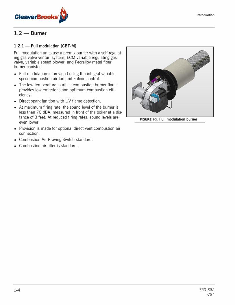
1.2.1 — Full modulation (CBT-M)
Full modulation units use a premix burner with a self-regulat-ing gas valve-venturi system, ECM variable regulating gas valve, variable speed blower, and Fecralloy metal fiber burner canister.
• Full modulation is provided using the integral variable speed combustion air fan and Falcon control.
• The low temperature, surface combustion burner flame provides low emissions and optimum combustion effi-ciency.
• Direct spark ignition with UV flame detection.• At maximum firing rate, the sound level of the burner is
less than 70 dBA, measured in front of the boiler at a dis-tance of 3 feet. At reduced firing rates, sound levels are even lower.
• Provision is made for optional direct vent combustion air connection.
• Combustion Air Proving Switch standard.• Combustion air filter is standard.
FIGURE 1-3. Full modulation burner
1-4 750-382CBT
Gas train
1.3 — Gas train
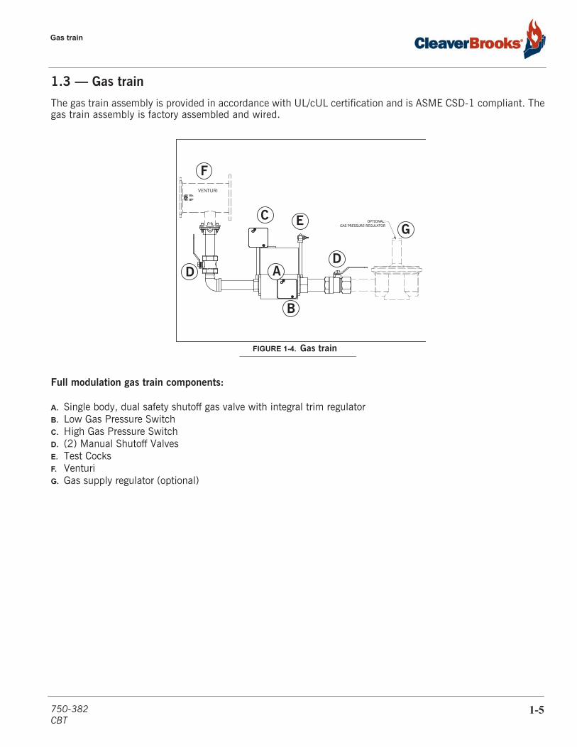
The gas train assembly is provided in accordance with UL/cUL certification and is ASME CSD-1 compliant. Thegas train assembly is factory assembled and wired.
Full modulation gas train components:
A. Single body, dual safety shutoff gas valve with integral trim regulatorB. Low Gas Pressure SwitchC. High Gas Pressure SwitchD. (2) Manual Shutoff ValvesE. Test CocksF. VenturiG. Gas supply regulator (optional)
VENTURI
OPTIONAL:GAS PRESSURE REGULATOR
FIGURE 1-4. Gas train
C
B
D
E
DA
F
G
750-382CBT
1-5
Introduction
1.4 — Controls
1.4.1 — Full modulation controls
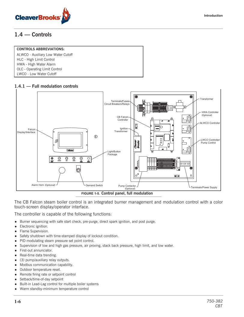
The CB Falcon steam boiler control is an integrated burner management and modulation control with a colortouch-screen display/operator interface.
The controller is capable of the following functions:
• Burner sequencing with safe start check, pre-purge, direct spark ignition, and post purge.• Electronic ignition.• Flame Supervision.• Safety shutdown with time-stamped display of lockout condition.• PID modulating steam pressure set point control.• Supervision of low and high gas pressure, air proving, stack back pressure, high limit, and low water.• First-out annunciator.• Real-time data trending.• (3) pump/auxiliary relay outputs.• Modbus communication capability.• Outdoor temperature reset.• Remote firing rate or setpoint control• Setback/time-of-day setpoint• Built-in Lead-Lag control for multiple boiler systems • Warm standby-minimum temperature control
CONTROLS ABBREVIATIONS:
ALWCO - Auxiliary Low Water CutoffHLC - High Limit ControlHWA - High Water AlarmOLC - Operating Limit ControlLWCO - Low Water Cutoff
(Optional)(Optional)
(Optional)
FIGURE 1-5. Control panel, full modulation
1-6 750-382CBT

Controls
Continue to next page
750-382CBT
1-7

Introduction
1.4.2 — Water level and limit controls, all boilers
The pressure transmitter provides an analog steam pressure signal to the controller for modulated firing.
The high limit control (HLC) provides safety shutdown when steam pressure exceeds the maximum operating range of the boiler. It includes a manual reset switch and adjustable set point.
The operating control (OLC) is set below the maximum pressure setting of the HLC. This control is auto reset and includes adjustable set point
Standard water level controls comprise an automatic reset primary low water cutoff (LWCO) and a manual reset auxiliary low water cutoff (ALWCO). A manual reset LWCO is available where required by code.
Four individual conductance probes are mounted within the LWCO water column to indicate levels for low water, pump on, pump off, and high water alarm (optional). The solid-state level control boards reside in the boiler control enclosure.
A panel mounted ALWCO reset/test switch is provided.
The water column blowdown should be piped to a boiler blowdown system. Please refer to service and maintenance section for blowdown procedures. FIGURE 1-6. Low water and limit controls
Steam pressure gauge
Manual valveALWCO probe
HLC
OLC
LWCO/pump control
Gauge glass
Gauge glass
Pressure transmitter
blowdown valve
WC blowdown valve
(modulating burneronly)
holder
1-8 750-382CBT

Component/connection locations
1.5 — Component/connection locations
Refer to Chapter 3 for recommended vent sizes and lengths.
FIGURE 1-7. Boiler components/connections, CBT
PRESSURE RELIEF VALVE
STACKOUTLET
AUX. LOW WATER CUTOFFSURFACE BLOWOFF PIPING
FEEDWATER PIPING
BLOWDOWN PIPING
LEVEL CONTROL
GAUGE GLASS
GASTRAIN
BURNERCABINET
CONTROLPANEL
AIRINLET
(OPTIONAL)
750-382CBT
1-9
Introduction
1.6 — Optional equipment
Certain options are available for the Model CBT Boiler; normally these will have been specified at the time oforder entry. In addition, some options may have been provided (by others) that are not part of Cleaver-Brooksscope of supply. In either case, the Cleaver-Brooks authorized representative should be consulted regardingspecific project requirements.
Model CBT optional features:
• Gas pressure regulator (>1/2 psig supply)• Gas pressure relief valve (>1 psig supply)• Minimum Temperature/Warm Standby• Direct vent kit combustion air adapter• Chemical feed system• Surface blow-off conductivity control• Feedwater system (includes tank, pump, and control) - shipped separately• Feedwater valves• Blowdown valves• Steam header valves• High water alarm• Time clock for setback control• Stack temperature limit control• Stack thermometer• Alarm horn• Lead-Lag steam pressure header transmitter• Feedwater sets and condensate receivers• Blowdown separators and tanks• Economizers• Complete steam skid or field-installed solutions• Factory mounted valves• Communications gateway• Boiler Monitor (remote connectivity)
1-10 750-382CBT
CHAPTER 2 Installation
Lifting and Moving the Boiler 2-2
Water Treatment 2-2
Boiler Room 2-4
Gas Piping 2-5
Boiler Waterside Connections 2-10
Electrical Connections 2-11
Wiring Diagrams 2-12
Provisions for combustion and ventilation air mustbe in accordance with UL 795, Commercial-Industrial Gas Heating Equipment, cUL, orapplicable provisions of the local building codes.Failure to follow this warning could result inpersonal injury or death
The boiler must be installed such that the gasignition system components are protected fromwater (dripping, spraying, rain, etc.) duringappliance operation and service. Failure to followthis warning could result in equipment failure.
! Warning ! Caution
If an external electrical source is utilized, the boiler,when installed, must be electrically bonded toground in accordance with the requirements of theauthority having jurisdiction or, in the absence ofsuch requirements, with the National ElectricalCode and/or UL 795, Commercial-Industrial GasHeating Equipment.
! Warning
750-382CBT
2-1
Installation
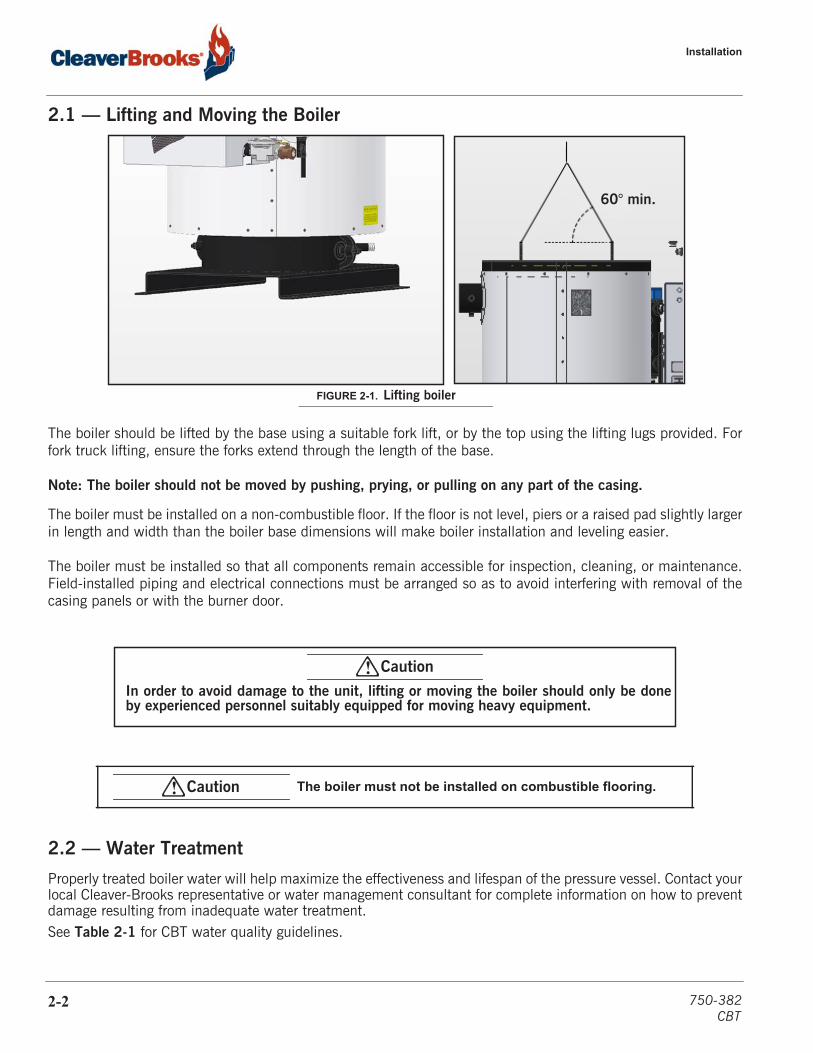
2.1 — Lifting and Moving the Boiler
The boiler should be lifted by the base using a suitable fork lift, or by the top using the lifting lugs provided. Forfork truck lifting, ensure the forks extend through the length of the base.
Note: The boiler should not be moved by pushing, prying, or pulling on any part of the casing.
The boiler must be installed on a non-combustible floor. If the floor is not level, piers or a raised pad slightly largerin length and width than the boiler base dimensions will make boiler installation and leveling easier.
The boiler must be installed so that all components remain accessible for inspection, cleaning, or maintenance.Field-installed piping and electrical connections must be arranged so as to avoid interfering with removal of thecasing panels or with the burner door.
2.2 — Water Treatment
Properly treated boiler water will help maximize the effectiveness and lifespan of the pressure vessel. Contact yourlocal Cleaver-Brooks representative or water management consultant for complete information on how to preventdamage resulting from inadequate water treatment.See Table 2-1 for CBT water quality guidelines.
The boiler must not be installed on combustible flooring.
FIGURE 2-1. Lifting boiler
60° min.
! CautionIn order to avoid damage to the unit, lifting or moving the boiler should only be doneby experienced personnel suitably equipped for moving heavy equipment.
! Caution
2-2 750-382CBT

Water Treatment
The CBT boiler requires soft water. Failure to observe this requirement can lead to dangerous operating conditions, and may result in damage to the boiler. If necessary, your Cleaver-Brooks representative can provide additional information regarding your water softening requirements.
The objectives of water treatment in general are to:
1. Prevent hard scale and soft sludge deposits that inhibit heat transfer and that could lead to overheated metal and costly downtime and repairs.
2. Eliminate corrosive gases in the supply or boiler water.
To accomplish these objectives, the boiler requires proper water treatment before and after introduction of waterinto the unit. The selection of pretreatment processes depends upon the water source, its chemical characteristics,the amount of makeup water needed, system operation practices, etc.
Because of the variables involved, no single boiler compound can be considered a cure-all; nor is it advisable toexperiment with homemade treating methods. A sound treatment program should include a weekly analysis of thewater in the system.
The internal or waterside surfaces of the pressure vessel should be inspected at regular intervals for evidence ofcorrosion, pitting, contamination, or accumulations of foreign matter. If any of these conditions are detected,contact your local Cleaver-Brooks authorized representative for advice on corrective action. It is recommended thata properly sized water meter be installed in the raw water makeup line to accurately determine the amount of rawwater admitted to the boiler.
Surface blow-off is available for steam boilers. This option allows removal of surface water impurities through ablowdown line located at the normal operating water level of the boiler. If allowed to accumulate, surfaceimpurities may impede steam release and could cause foaming, leading to priming and carryover in the steamlines.
Corrosion and sludge deposits in old systems must be removed prior to installation of a new boiler.
TABLE 2- 1. CBT water quality
QUANTITY LIMITSOxygen <0.005 ppmCO2 0 ppmHardness <2.0 ppmSuspended Solids <300 ppmpH 8.5 - 10.5Sulfite >50 ppmFe <0.1 ppmSilica <150 ppmTotal Alkalinity <700 ppmDissolved Solids <3,000 ppm
Important!
! WarningInadequate or improper water treatment will shorten the life of the boiler and could result in a hazardous condition.
750-382CBT
2-3
Installation
2.3 — Boiler Room
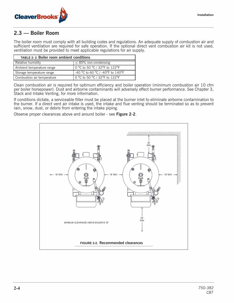
The boiler room must comply with all building codes and regulations. An adequate supply of combustion air andsufficient ventilation are required for safe operation. If the optional direct vent combustion air kit is not used,ventilation must be provided to meet applicable regulations for air supply.
Clean combustion air is required for optimum efficiency and boiler operation (minimum combustion air 10 cfmper boiler horsepower). Dust and airborne contaminants will adversely effect burner performance. See Chapter 3,Stack and Intake Venting, for more information.If conditions dictate, a serviceable filter must be placed at the burner inlet to eliminate airborne contamination tothe burner. If a direct vent air intake is used, the intake and flue venting should be terminated so as to preventrain, snow, dust, or debris from entering the intake piping.Observe proper clearances above and around boiler - see Figure 2-2.
TABLE 2- 2. Boiler room ambient conditionsRelative humidity < 85% non-condensingAmbient temperature range 0 oC to 50 oC / 32oF to 122oFStorage temperature range -40 oC to 60 oC / -40oF to 140oFCombustion air temperature 0 oC to 50 oC / 32oF to 122oF
FIGURE 2-2. Recommended clearances
2-4 750-382CBT
Gas Piping
2.4 — Gas Piping
Gas pressure requirements - For proper and safe operation, each Model CBT boiler requires a stable gas pressureinput. The minimum inlet supply pressure must be as noted in Table 2-3. Pressure should be measured when theburner is firing using a manometer at the upstream test port connection on the main gas valve. For a multipleunit installation, gas pressure should be set for a single unit first, then the remaining units should be staged on toensure that gas pressure droop is not more than 1" w.c. and never below the required pressure. Fluctuating gaspressure readings could be indicative of a faulty supply regulator or improper gas train size to the boiler.
*Maximum without upstream regulator
A manually operated shut-off valve is provided as standard on the CBT boiler. If dirt particles are present in thegas supply, it may be necessary to install an approved gas filter. Please inquire with the local gas supply company.The boiler shall be installed such that the gas ignition system components are protected from water (dripping,spraying, etc.) during appliance operation and service.
TABLE 2- 3. Model CBT gas pressure requirements
CBT Size
(HP)
Natural Gas LP Gas
Min (“WC) Max (“WC)* Min (“WC) Max (“WC)*
9.5 7.0 14 11.0 14
10 7.0 14 11.0 14
15 7.0 14 11.0 14
20 7.0 14 11.0 14
25 7.0 14 11.0 14
30 11.0 14 11.0 14
40 11.0 14 11.0 14
50 11.0 14 11.0 14
A sediment trap must be provided upstream of the gas controls.
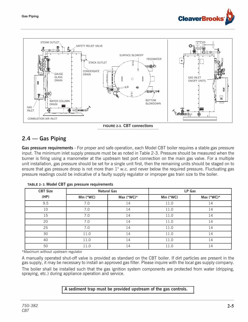
FIGURE 2-3. CBT connections
STACK OUTLET
CONDENSATE DRAIN
SAFETY RELIEF VALVE
WATER COLUMNDRAIN
GASINLET
GAS INLETON/OFF UNITS
STEAM OUTLET
COMBUSTION AIR INLET
SURFACE BLOWOFFFEEDWATER
BOTTOMBLOWDOWN
GAUGEGLASSDRAIN
750-382CBT
2-5

Installation
If building supply gas pressure is greater than 1 psig (27.8” WC), an upstream regulator with overpressure pro-tection and proper gas venting will be required and must be piped to a safe point of discharge. For multiple boil-ler installations, a dedicated gas pressure regulator is required for each boiler to ensure consistent gas pressure at the boiler.
Drip legs are required on any vertical piping at the gas supply to each boiler so that any dirt, weld slag, or debris can deposit in the drip leg rather than into the boiler gas train. The bottom of the drip leg should be removable without disassembling any gas piping. The connected piping to the boiler should be supported from pipe sup-ports and not supported by the boiler gas train or the bottom of the drip leg.
All gas piping and components to the boiler gas train connection must comply with NFPA 54, local codes, and utility requirements as a minimum. Only gas approved fittings, valves, or pipe should be used. Standard industry practice for gas piping is normally Schedule 40 black iron pipe and fittings.
Before starting the unit(s) all piping must be cleaned to prevent the entrance of debris into the boiler gas train. Piping should be tested as noted in NFPA 54, with the boiler isolated during tests.
After initial startup, the inlet screen to the gas valve should be checked and cleaned for any debris buildup.
Gas Supply Pipe Sizing - For proper operation of a single unit or a multiple unit installation, we recommend that the gas piping be sized to allow no more than 0.3" w.c. pressure drop from the source (gas header or utility meter) to the final unit location. Higher supply pressure systems may allow for a greater pressure drop. In ALL cases, minimum supply pressures must be met for proper operation of the boiler(s). The gas supplier (utility) should be consulted to confirm that sufficient volume and normal pressure are provided to the building at the discharge side of the gas meter or supply pipe.
For installations of new boilers into an existing building, gas pressure should be measured with a manometer to ensure sufficient pressure is available. A survey of all connected “gas using devices” should be made. If appli-ances other than the boiler or boilers are connected to the gas supply line, then a determination must be made of how much flow volume will be demanded at one time and the pressure drop requirement when all appliances are firing.
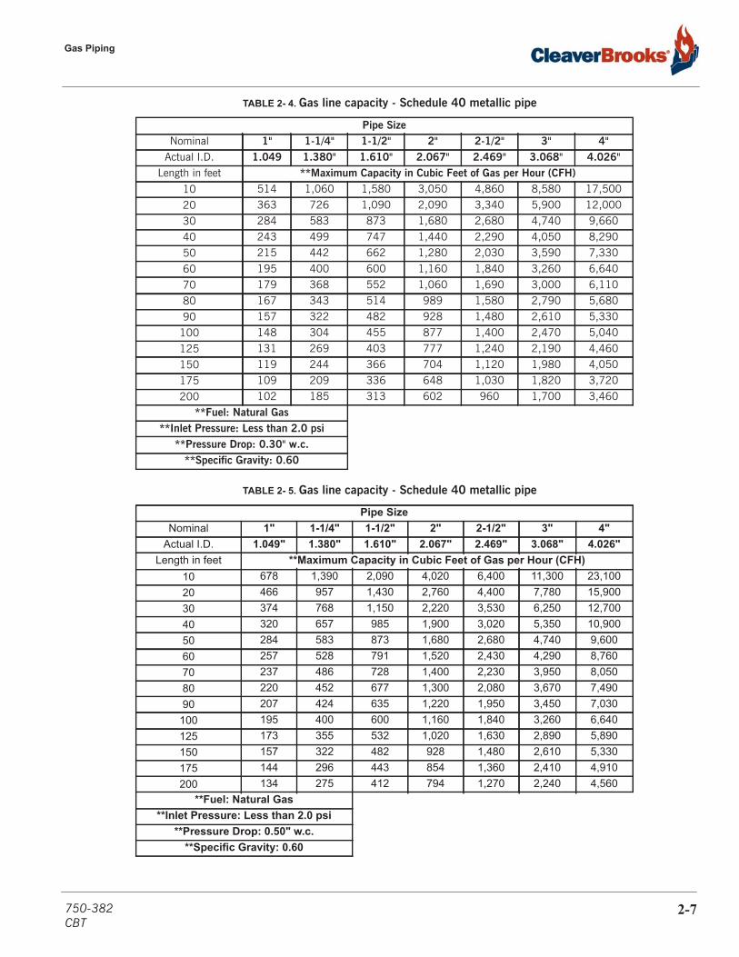
The total length of gas piping and all fittings must be considered when sizing the gas piping. Total equivalent length should be calculated from the utility meter or source to the final unit connection. As a minimum guideline, gas piping Tables 2-4 and 2-5 should be used. The data in these tables is from the NFPA 54 source book, 2006 edition.
To verify the input of each device that is connected to the gas piping, obtain the btu/hr input and divide this input by the calorific value of the gas that will be utilized. For instance, a 40 HP unit with 1,613,253 btu/hr input divided by a gas calorific value of 1060 will result in a flow of 1,522 CFH (cubic ft/hr). The single boiler is approximately 20 feet from the gas supply header source. And with a measured gas supply pressure of 10" w.c. we find from Table 2-4 that a supply pipe size of 2" should be used as a minimum.
2-6 750-382CBT
Gas Piping
TABLE 2- 4. Gas line capacity - Schedule 40 metallic pipe
TABLE 2- 5. Gas line capacity - Schedule 40 metallic pipe
Pipe SizeNominal 1" 1-1/4" 1-1/2" 2" 2-1/2" 3" 4"
Actual I.D. 1.049 1.380" 1.610" 2.067" 2.469" 3.068" 4.026"Length in feet **Maximum Capacity in Cubic Feet of Gas per Hour (CFH)
10 514 1,060 1,580 3,050 4,860 8,580 17,50020 363 726 1,090 2,090 3,340 5,900 12,00030 284 583 873 1,680 2,680 4,740 9,66040 243 499 747 1,440 2,290 4,050 8,29050 215 442 662 1,280 2,030 3,590 7,33060 195 400 600 1,160 1,840 3,260 6,64070 179 368 552 1,060 1,690 3,000 6,11080 167 343 514 989 1,580 2,790 5,68090 157 322 482 928 1,480 2,610 5,330
100 148 304 455 877 1,400 2,470 5,040125 131 269 403 777 1,240 2,190 4,460150 119 244 366 704 1,120 1,980 4,050175 109 209 336 648 1,030 1,820 3,720200 102 185 313 602 960 1,700 3,460
**Fuel: Natural Gas**Inlet Pressure: Less than 2.0 psi
**Pressure Drop: 0.30" w.c.**Specific Gravity: 0.60
Pipe SizeNominal 1" 1-1/4" 1-1/2" 2" 2-1/2" 3" 4"
Actual I.D. 1.049" 1.380" 1.610" 2.067" 2.469" 3.068" 4.026"Length in feet **Maximum Capacity in Cubic Feet of Gas per Hour (CFH)
10 678 1,390 2,090 4,020 6,400 11,300 23,10020 466 957 1,430 2,760 4,400 7,780 15,90030 374 768 1,150 2,220 3,530 6,250 12,70040 320 657 985 1,900 3,020 5,350 10,90050 284 583 873 1,680 2,680 4,740 9,60060 257 528 791 1,520 2,430 4,290 8,76070 237 486 728 1,400 2,230 3,950 8,05080 220 452 677 1,300 2,080 3,670 7,49090 207 424 635 1,220 1,950 3,450 7,030
100 195 400 600 1,160 1,840 3,260 6,640125 173 355 532 1,020 1,630 2,890 5,890150 157 322 482 928 1,480 2,610 5,330175 144 296 443 854 1,360 2,410 4,910200 134 275 412 794 1,270 2,240 4,560
**Fuel: Natural Gas**Inlet Pressure: Less than 2.0 psi
**Pressure Drop: 0.50" w.c.**Specific Gravity: 0.60
750-382CBT
2-7
Installation
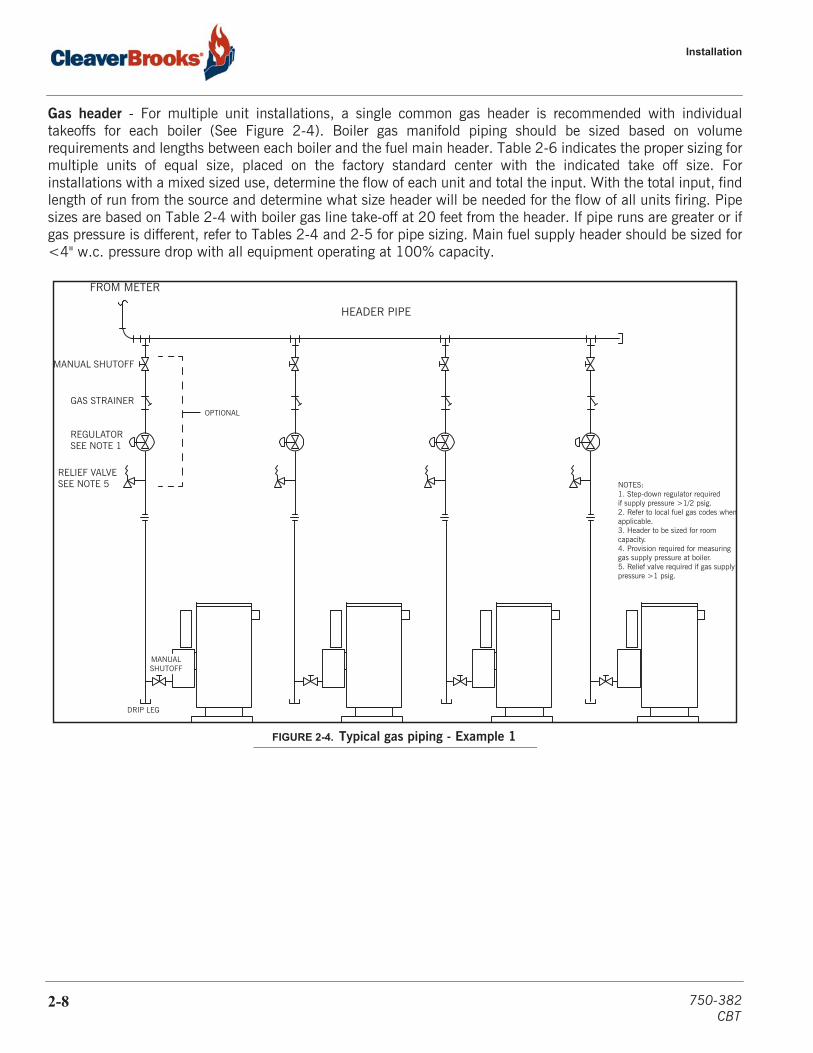
Gas header - For multiple unit installations, a single common gas header is recommended with individualtakeoffs for each boiler (See Figure 2-4). Boiler gas manifold piping should be sized based on volumerequirements and lengths between each boiler and the fuel main header. Table 2-6 indicates the proper sizing formultiple units of equal size, placed on the factory standard center with the indicated take off size. Forinstallations with a mixed sized use, determine the flow of each unit and total the input. With the total input, findlength of run from the source and determine what size header will be needed for the flow of all units firing. Pipesizes are based on Table 2-4 with boiler gas line take-off at 20 feet from the header. If pipe runs are greater or ifgas pressure is different, refer to Tables 2-4 and 2-5 for pipe sizing. Main fuel supply header should be sized for<4" w.c. pressure drop with all equipment operating at 100% capacity.
FIGURE 2-4. Typical gas piping - Example 1
MANUALSHUTOFF
DRIP LEG
MANUAL SHUTOFF
GAS STRAINER
REGULATORSEE NOTE 1
RELIEF VALVESEE NOTE 5
OPTIONAL
FROM METER
HEADER PIPE
NOTES:1. Step-down regulator required if supply pressure >1/2 psig.2. Refer to local fuel gas codes whenapplicable.3. Header to be sized for room capacity.4. Provision required for measuringgas supply pressure at boiler.5. Relief valve required if gas supplypressure >1 psig.
2-8 750-382CBT

Gas Piping
TABLE 2- 6. Pipe sizing for multiple unit manifolds
9.5 HPNumber of Boilers
10 HPNumber of Boilers
1 2 3 4 1 2 3 4
Pipe size to boiler 1-1/4” 1-1/4” 1-1/4” 1-1/4” Pipe size to boiler 1-1/4” 1-1/4” 1-1/4” 1-1/4”
Header pipe size 1-1/4” 1-1/4” 2” 2” Header pipe size 1-1/4” 1-1/4” 2” 2”
15 HPNumber of Boilers
20 HPNumber of Boilers
1 2 3 4 1 2 3 4
Pipe size to boiler 1-1/4” 1-1/4” 1-1/4” 1-1/4” Pipe size to boiler 1-1/2” 1-1/2” 1-1/2” 1-1/2”
Header pipe size 1-1/4” 2” 2” 2-1/2” Header pipe size 1-1/2” 2” 2-1/2” 2-1/2”
25 HPNumber of Boilers
30 HPNumber of Boilers
1 2 3 4 1 2 3 4
Pipe size to boiler 1-1/2” 1-1/2” 1-1/2” 1-1/2” Pipe size to boiler 2” 2” 2” 2”
Header pipe size 1-1/2” 2” 2-1/2” 3” Header pipe size 2” 2-1/2” 3” 3”
40 HPNumber of Boilers
50 HPNumber of Boilers
1 2 3 4 1 2 3 4
Pipe size to boiler 2” 2” 2” 2” Pipe size to boiler 2” 2” 2” 2”
Header pipe size 2” 2-1/2” 3” 4” Header pipe size 2” 3” 3” 4”
FIGURE 2-5. Typical gas piping - Example 2
DRIP LEG REQUIRED FOR ANY VERTICAL RUN OF PIPING
GAS HEADER - SIZE FOR BOILER ROOMCAPACITY AND TO MINIMIZE PRESSURE LOSS
MANUAL SHUTOFFVALVE
MANUAL SHUTOFFVALVE
REGULATOR (OPTIONAL)
BY INSTALLER
STRAINER
750-382CBT
2-9
Installation
2.5 — Boiler Waterside Connections
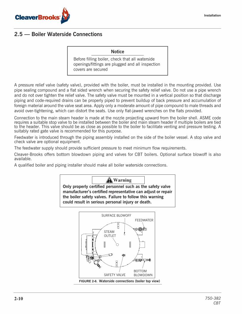
A pressure relief valve (safety valve), provided with the boiler, must be installed in the mounting provided. Usepipe sealing compound and a flat sided wrench when securing the safety relief valve. Do not use a pipe wrenchand do not over tighten the relief valve. The safety valve must be mounted in a vertical position so that dischargepiping and code-required drains can be properly piped to prevent buildup of back pressure and accumulation offoreign material around the valve seat area. Apply only a moderate amount of pipe compound to male threads andavoid over-tightening, which can distort the seats. Use only flat-jawed wrenches on the flats provided.
Connection to the main steam header is made at the nozzle projecting upward from the boiler shell. ASME coderequires a suitable stop valve to be installed between the boiler and main steam header if multiple boilers are tiedto the header. This valve should be as close as possible to the boiler to facilitate venting and pressure testing. Asuitably rated gate valve is recommended for this purpose.Feedwater is introduced through the piping assembly installed on the side of the boiler vessel. A stop valve andcheck valve are optional equipment.The feedwater supply should provide sufficient pressure to meet minimum flow requirements.Cleaver-Brooks offers bottom blowdown piping and valves for CBT boilers. Optional surface blowoff is alsoavailable.A qualified boiler and piping installer should make all boiler waterside connections.
Notice
Before filling boiler, check that all waterside openings/fittings are plugged and all inspection covers are secured
! WarningOnly properly certified personnel such as the safety valve manufacturer’s certified representative can adjust or repair the boiler safety valves. Failure to follow this warning could result in serious personal injury or death.
SURFACE BLOWOFFFEEDWATER
BOTTOMBLOWDOWN
STEAMOUTLET
SAFETY VALVE
FIGURE 2-6. Waterside connections (boiler top view)
2-10 750-382CBT
Electrical Connections
2.6 — Electrical Connections
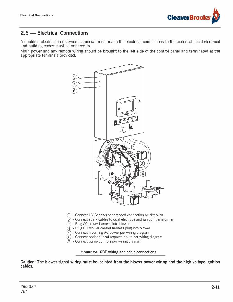
A qualified electrician or service technician must make the electrical connections to the boiler; all local electricaland building codes must be adhered to.Main power and any remote wiring should be brought to the left side of the control panel and terminated at theappropriate terminals provided.
Caution: The blower signal wiring must be isolated from the blower power wiring and the high voltage ignitioncables.
FIGURE 2-7. CBT wiring and cable connections
- Connect UV Scanner to threaded connection on dry oven- Connect spark cables to dual electrode and ignition transformer- Plug AC power harness into blower- Plug DC blower control harness plug into blower- Connect incoming AC power per wiring diagram- Connect optional heat request inputs per wiring diagram- Connect pump controls per wiring diagram
1234567
750-382CBT
2-11
Installation
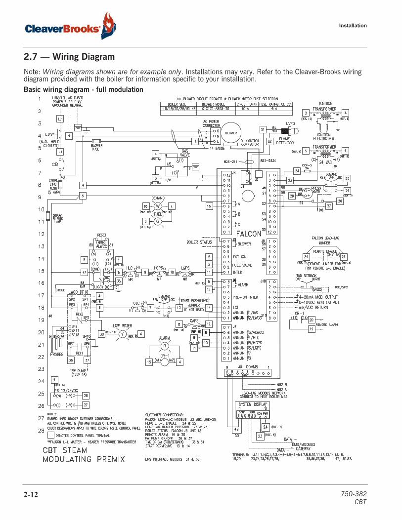
2.7 — Wiring Diagram
Note: Wiring diagrams shown are for example only. Installations may vary. Refer to the Cleaver-Brooks wiring diagram provided with the boiler for information specific to your installation.Basic wiring diagram - full modulation
2-12 750-382CBT

CHAPTER 3 Flue and Combustion Air Venting
Venting connections - general 3-2
Flue venting 3-2
Vent terminal location 3-2
Horizontal through-wall venting, inside air (Category III) 3-5
Horizontal through-wall direct venting 3-6
Horizontal through-wall flue vent termination 3-7
Vertical venting, inside combustion air (Category III) central heating 3-8
Vertical venting direct vent combustion air (Category III) 3-9
Flue and combustion air duct design 3-9
750-382CBT
3-1

Flue and Combustion Air Venting
3.1 — Venting connections - general
Proper installation of flue gas exhaust venting is critical for the efficient and safe operation of the boiler.Definition of Appliance CategoriesBoilers are divided into four categories based on the pressure and temperature produced in the exhauststack and the likelihood of condensate production in the vent.• Category I - A boiler which operates with a non-positive vent static pressure and with a vent gas temperature
that avoids excessive condensate production in the vent.• Category II - A boiler which operates with a non-positive vent static pressure and with a vent gas temperature
that may cause excessive condensate production in the vent.• Category III - A boiler which operates with a positive vent pressure and with a vent gas temperature that avoids
excessive condensate production in the vent.• Category IV - A boiler which operates with a positive vent pressure and with a vent gas temperature that may
cause excessive condensate production in the vent.The Model CBT will in most applications be considered a Category III boiler. In certain applications, such aswith a condensing economizer, Category II or IV venting criteria may apply.
For additional information on boiler categorization, see latest edition standard of National Fuel Gas Code or inCanada, the latest edition of CGA Standard B149 Installation Code for Gas Burning Appliances and Equipment,or applicable provisions of local building codes.
During winter months check the flue termination and make sure no blockage occurs from build up of ice orsnow. Condensate can freeze on a flue termination. Frozen condensation at the flue termination can result in ablocked flue condition.
3.2 — Flue venting
The flue should be supported to maintain proper clearances from combustible materials.Use insulated vent pipe spacers where the venting passes through combustible roofs and walls.
Cleaver-Brooks recommends the use of flue venting systems that are certified to UL 103 or ULC C-959.Flue systems constructed of stainless steel are recommended. Please note: Type B vent is NOT appropriatefor Category II, III, or IV boiler systems.
3.3 — Vent terminal location
Give special attention to the location of the vent termination to avoid possibility of property damage orpersonal injury.1. Combustion gases can form a white vapor plume in the winter. The plume could obstruct a window view if
the termination is installed in close proximity to windows. 2. Prevailing winds could cause freezing of condensate and water/ice buildup on building, plants or roof.
Contact the manufacturer of the vent material if there is anyquestion about the boiler categorization and suitability of avent material for application on a Category III vent system.Using improper venting materials can result in personalinjury, death or property damage.
3-2 750-382CBT
Vent terminal location
3. The bottom of the vent terminal and the air intake shall be located at least 24 inches above grade, includingnormal snow line.
4. Un-insulated single-wall metal vent pipe shall not be used outside in cold climates for venting combustiongas.
5. Through-the-wall vents for Category II and IV appliances and non-categorized condensing appliances shallnot terminate over public walkways or over an area where condensate or vapor could create a nuisance orhazard or could be detrimental to the operation of other equipment. Where local experience indicates thatcondensate is a problem with Category III appliances, this provision shall also apply.
6. Locate and guard vent termination to prevent accidental contact by people and pets. 7. DO NOT terminate vent in window well, alcove, stairwell or other recessed area, unless previously approved
by local authority. 8. DO NOT terminate above any door, window, or gravity air intake. Condensate can freeze causing ice
formations. 9. Locate or guard vent to prevent condensate from damaging exterior finishes. Use a 2' x 2' rust resistant sheet
metal backing plate against brick or masonry surfaces. 10. Minimize exposed flue venting outside of building in extreme cold climates. In winter conditions condensate
could freeze and block the flue pipe or termination. 11. Ensure combustion air intake(s) are a sufficient distant away from any exhaust terminations to avoid drawing
in flue gases or other contaminants.
U.S. installations- Refer to latest edition of the National Fuel Gas Code. Vent termination requirements are as follows: 1. Vent must terminate at least four (4) feet below, four (4) feet horizontally, or one (1) foot above any door,
window or gravity air inlet to the building. 2. The vent must not be less than seven (7) feet above grade when located adjacent to public walkways. 3. Terminate vent at least three (3) feet above any forced air inlet located within ten (10) feet. 4. Vent must terminate at least four (4) feet horizontally, and in no case above or below unless four (4) feet
horizontal distance is maintained, from electric meters, gas meters, regulators, and relief equipment. 5. Terminate vent at least six (6) feet away from adjacent walls. 6. DO NOT terminate vent closer than five (5) feet below roof overhang.Canada installations- Refer to the latest edition of CAN/CGA-B149.1 and B149.2 A vent shall not terminate: 1. Directly above a paved sidewalk or driveway which is located between two single family dwellings and serves
both dwellings. 2. Less than 7 ft. (2.13m) above a paved sidewalk or paved driveway located on public property. 3. Within 6 ft. (1.8m) of a mechanical air supply inlet to any building. 4. Above a meter/regulator assembly within 3 ft. (900mm) horizontally of the vertical center-line of the regulator.
5. Within 6 ft. (1.8m) if any gas service regulator vent outlet. 6. Less than 1 ft. (300mm) above grade level. 7. Within 3 ft. (1m) of a window or door which can be opened in any building, any non-mechanical air supply
inlet to any building to the combustion air inlet of any other appliance. 8. Underneath a verandah, porch or deck, unless:
A. The verandah, porch or deck is fully open on a minimum of two sides beneath the floor. B. the distance between the top of the vent termination and the underside of the verandah, porch or deck is
greater than 1 ft. (30cm)Note: For direct vent installations where the air is piped in from outside, a protective screen on the air inlettermination elbow must be used to act as an inlet screen.
750-382CBT
3-3

Flue and Combustion Air Venting
Examine the venting system at least once a year. Check all joints and vent pipe connections for tightness,corrosion or deterioration.
3.3.1 — Venting installation tips
Where to support piping:• Horizontal runs- at least every five (5) feet.• Vertical runs - use braces under or near elbows
Observe the following to avoid personal injury or property damage:• To cut nonmetallic vent pipe, use a fine-toothed hacksaw (34 teeth per inch).• Do not use nonmetallic vent pipe or fittings that are cracked or damaged.• Do not use nonmetallic vent fittings if they are cut or altered.• Do not drill holes, or use screws or rivets, in nonmetallic vent pipe or fittings.
Refer also to the vent manufacturer’s installation instructions.
During winter months check the flue termination and make sure no blockage occurs from build up of ice or snow. Condensate can freeze on a flue termination. Frozen condensation at the flue termination can result in a blocked flue condition.
FIGURE 3-1. Vent terminations
3-4 750-382CBT

Horizontal through-wall venting, inside air (Category III)
3.4 — Horizontal through-wall venting, inside air (Category III)
For boilers connected to gas vents or chimneys, vent installa-tions shall be in accordance with Part 7, Venting of Equipment, of the latest edition of National Fuel Gas Code, or in Canada, the latest edition of CAN/CGA-B 149.1 and.2 Installation Code for Gas Burning Appliances and Equipment, or applicable provi-sions of local building codes.
These installations utilize the boiler-mounted blower to vent the combustion products to the outside. Combustion air is taken from inside the room and the vent is installed horizontally through the wall to the outside. Adequate combustion and venti-lation air must be supplied to the boiler room in accordance with the National Fuel Gas Code or, in Canada, the latest edition of CAN/CGA-B 149.1 and.2 Installation Code for Gas Burning Appliances and Equipment.
The direct vent intake should be considered in the overall length calculation of the venting system.
The vent must be installed to prevent the flue gas leakage. Care must be taken during assembly to insure that all joints are sealed properly and are airtight.
The vent must be installed to prevent the potential accumulation of condensate in the vent pipes. It is recom-mended that:
1. The flue venting be installed with a slight downward slope of at least 1/8” per foot of horizontal run to the vent terminal.
2. The flue venting be insulated through the length of the horizontal run.
For appliances installed in extreme cold climate, it is recommended that:
1. The flue venting be installed with a slight upward slope of at least 1/8” per foot of horizontal run to the vent terminal. In this case, an approved condensate trap must be installed per applicable codes.
2. The flue venting be insulated through the length of the horizontal run.
FIGURE 3-2. Horizontal venting through-wall using inside air for combustion
750-382CBT
3-5

Flue and Combustion Air Venting
3.5 — Horizontal through-wall direct venting
These installations utilize the boiler mounted blower to draw combustion air from outside and vent combustion gases to the outside.
Combustion air venting can be constructed of steel, stainless steel, PVC, CPVC, or material as deemed appropri-ate for the application and per local codes. The direct vent air intake should be considered in the overall length calculation of the venting system.
Care must be taken during assembly that all joints are sealed properly and are airtight for both the combustion air intake and the exhaust flue piping system.
The flue venting must be installed to prevent the potential accumulation of condensate in the stack pipes. It is recommended that:
1. Vent be installed with a slight downward slope of at least 1/8” per foot of horizontal run to the stack terminal. 2. The flue venting is to be insulated through the length of the horizontal run.
For appliances installed in extreme cold climate, it is recommended that:
FIGURE 3-3. Horizontal through-wall direct venting system, Category III installation
3-6 750-382CBT
Horizontal through-wall flue vent termination
1. The flue venting be installed with a slight upward slope of at least 1/8” per foot of horizontal run to the vent terminal. In this case, an approved condensate trap must be installed per applicable codes.
2. The flue venting is to be insulated through the length of the horizontal run.
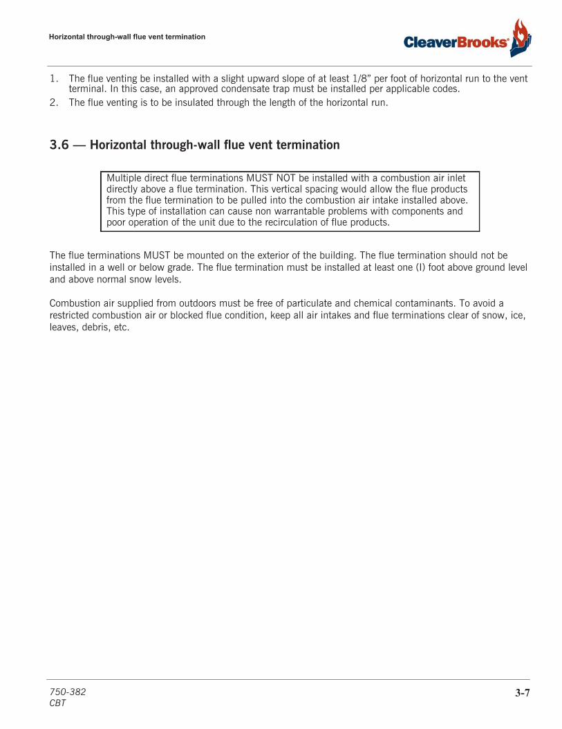
3.6 — Horizontal through-wall flue vent termination
The flue terminations MUST be mounted on the exterior of the building. The flue termination should not be installed in a well or below grade. The flue termination must be installed at least one (I) foot above ground level and above normal snow levels.
Combustion air supplied from outdoors must be free of particulate and chemical contaminants. To avoid a restricted combustion air or blocked flue condition, keep all air intakes and flue terminations clear of snow, ice, leaves, debris, etc.
Multiple direct flue terminations MUST NOT be installed with a combustion air inlet directly above a flue termination. This vertical spacing would allow the flue products from the flue termination to be pulled into the combustion air intake installed above. This type of installation can cause non warrantable problems with components and poor operation of the unit due to the recirculation of flue products.
750-382CBT
3-7
Flue and Combustion Air Venting
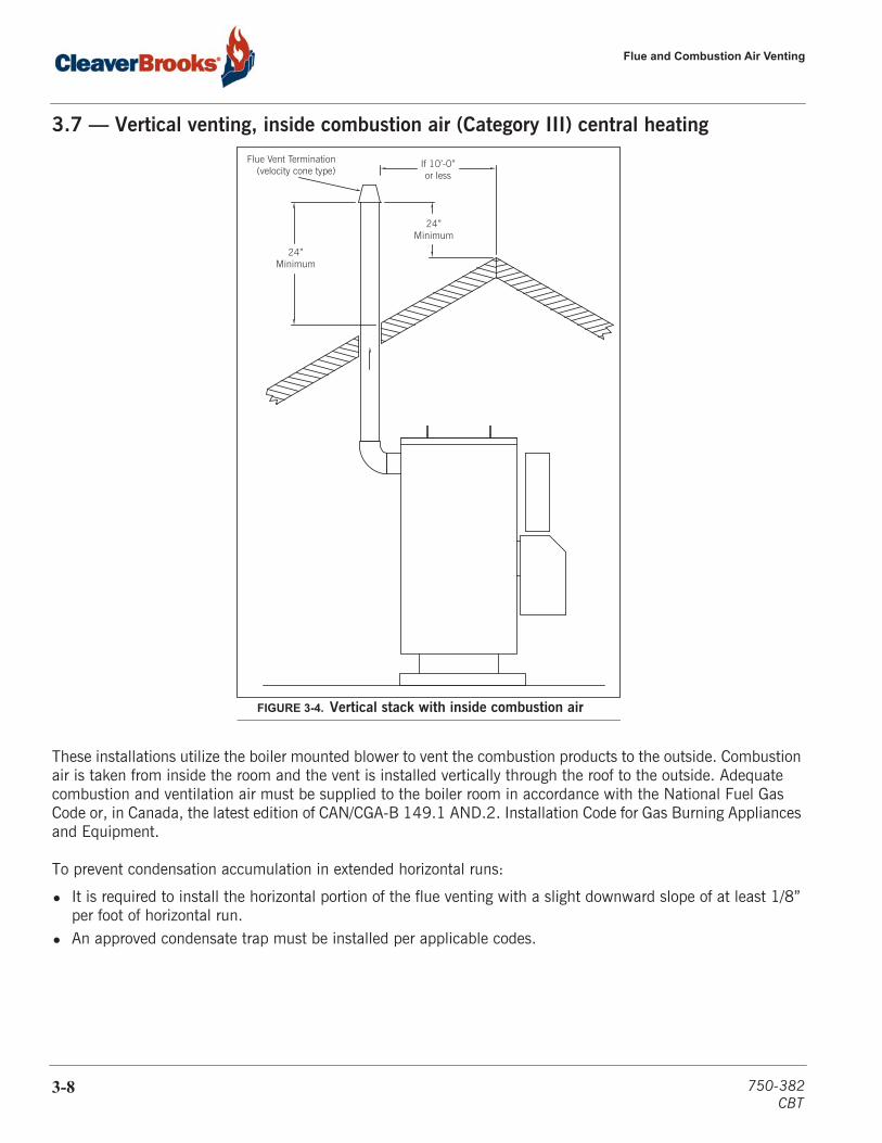
3.7 — Vertical venting, inside combustion air (Category III) central heating
These installations utilize the boiler mounted blower to vent the combustion products to the outside. Combustion air is taken from inside the room and the vent is installed vertically through the roof to the outside. Adequate combustion and ventilation air must be supplied to the boiler room in accordance with the National Fuel Gas Code or, in Canada, the latest edition of CAN/CGA-B 149.1 AND.2. Installation Code for Gas Burning Appliances and Equipment.
To prevent condensation accumulation in extended horizontal runs:
• It is required to install the horizontal portion of the flue venting with a slight downward slope of at least 1/8” per foot of horizontal run.
• An approved condensate trap must be installed per applicable codes.
Flue Vent Termination (velocity cone type)
If 10’-0”or less
24”Minimum
24”Minimum
FIGURE 3-4. Vertical stack with inside combustion air
3-8 750-382CBT

Vertical venting direct vent combustion air (Category III)
3.8 — Vertical venting direct vent combustion air (Category III)
These installations utilize the boiler mounted blower to draw combustion air from outside and vent combustion products to the outside. A positive pressure venting system is required.
To prevent condensation accumulation in extended horizontal runs, it is required to install the horizontal portion of the flue venting with a slight upward slope of at least 1/8” per foot of horizontal run; a drain with condensate trap must be installed per applicable codes.
Combustion air venting can be constructed of steel, stainless steel, PVC, CPVC, or material as deemed appropri-ate for the application and per local codes.
3.9 — Flue and combustion air duct designTABLE 3- 1. Stack/comb. air connections & max. air intake length
*Each additional 90 deg. elbow equals 5 equivalent feet of ductwork. Subtract from the maximum length accordingly. Increasing the diameter ofthe air intake will reduce the pressure drop and thereby allow longer total vent lengths. Maximum allowable pressure drop in combustion air intakeduct is 0.25” w.c.**The maximum allowable draft tolerance in the flue venting is +/- 0.25” w.c. as measured at the boiler's flue outlet.
Boiler Size HP Stack Connection - Flue diameter (in)**
Combustion Air Duct diameter (in)
Maximum Air Intake Length (ft)*
9.5 6 4 120
10 6 4 160
15 6 4 140
20 6 4 120
25 64 100
6 140
30 8 6 120
40 8 6 100
50 8 8 100
Air Intake (w/Screen)
36”Minimum
12” Minimum
24” Minimum
Flue Vent Termination (velocity cone type)
FIGURE 3-5. Vertical stack with direct vent combustion air
750-382CBT
3-9

Flue and Combustion Air Venting
3-10 750-382CBT
CHAPTER 4 Commissioning
Commissioning 4-2Operating conditions 4-2Filling boiler 4-2Control setpoints 4-2Water level controls 4-2CB Falcon setup 4-4CB Falcon display/operator interface 4-5Lockouts, Holds, and Alerts 4-9Controller configuration 4-10Program module 4-17Burner sequence 4-17Fan speed settings 4-18Initial startup procedure 4-18Gas train and piping 4-18Power-up 4-19Operation check: gas valve, gas pressure switches, and combustion air proving switch 4-20LWCO and ALWCO Check 4-21Low and high fire adjustments 4-22Modulation OFF point 4-22Setting Combustion 4-22Limit Controls Check 4-24
Boil-out of a new unit 4-25Post start-up checkout procedure 4-26Falcon control functions and customer interface 4-26
The boiler and its gas connection must be leak testedbefore placing the boiler in operation.
! Warning
750-382CBT
4-1
Commissioning
4.1 — Commissioning
4.1.1 — Operating conditions
• The installation site should be as free as possible from vibration, dust, and corrosive media
• The controllers should be located as far as possible from sources of electromagnetic fields, such as frequency converters or high-voltage ignition transformers
• Control panel must be connected to earth ground.
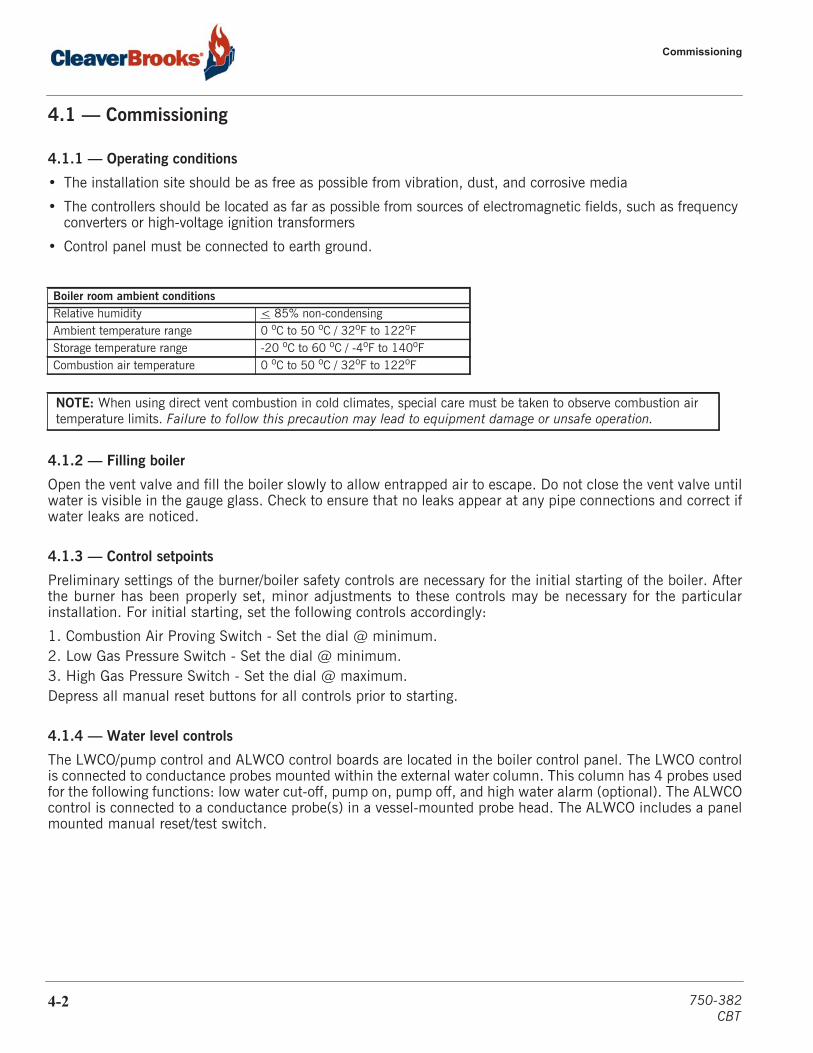
4.1.2 — Filling boiler
Open the vent valve and fill the boiler slowly to allow entrapped air to escape. Do not close the vent valve untilwater is visible in the gauge glass. Check to ensure that no leaks appear at any pipe connections and correct ifwater leaks are noticed.
4.1.3 — Control setpoints
Preliminary settings of the burner/boiler safety controls are necessary for the initial starting of the boiler. Afterthe burner has been properly set, minor adjustments to these controls may be necessary for the particularinstallation. For initial starting, set the following controls accordingly:
1. Combustion Air Proving Switch - Set the dial @ minimum.2. Low Gas Pressure Switch - Set the dial @ minimum.3. High Gas Pressure Switch - Set the dial @ maximum.Depress all manual reset buttons for all controls prior to starting.
4.1.4 — Water level controls
The LWCO/pump control and ALWCO control boards are located in the boiler control panel. The LWCO controlis connected to conductance probes mounted within the external water column. This column has 4 probes usedfor the following functions: low water cut-off, pump on, pump off, and high water alarm (optional). The ALWCOcontrol is connected to a conductance probe(s) in a vessel-mounted probe head. The ALWCO includes a panelmounted manual reset/test switch.
Boiler room ambient conditionsRelative humidity < 85% non-condensingAmbient temperature range 0 oC to 50 oC / 32oF to 122oFStorage temperature range -20 oC to 60 oC / -4oF to 140oFCombustion air temperature 0 oC to 50 oC / 32oF to 122oF
NOTE: When using direct vent combustion in cold climates, special care must be taken to observe combustion air temperature limits. Failure to follow this precaution may lead to equipment damage or unsafe operation.
4-2 750-382CBT

Commissioning
Continue to next page
750-382CBT
4-3

Commissioning
4.1.5 — CB Falcon setup
The Model CBT boiler uses the CB Falcon boiler control system. Primary controller functions include:
• Flame supervision• Burner sequencing• PID Modulation control• Operating Limit Control
Additional features include:
• User-friendly touchscreen interface• Modbus communication capability• Alarm/lockout messaging with history (last 15 messages)• Annunciation• Password protection of configurable parameters• Time of Day (dual setpoint) control• Remote reset• (3) configurable pump relays• Remote modulation/remote setpoint
FIGURE 4-1. CB Falcon controller
4-4 750-382CBT
Commissioning
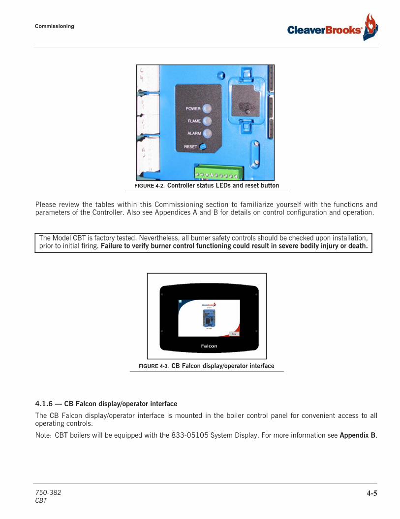
Please review the tables within this Commissioning section to familiarize yourself with the functions andparameters of the Controller. Also see Appendices A and B for details on control configuration and operation.
4.1.6 — CB Falcon display/operator interface
The CB Falcon display/operator interface is mounted in the boiler control panel for convenient access to alloperating controls.
Note: CBT boilers will be equipped with the 833-05105 System Display. For more information see Appendix B.
The Model CBT is factory tested. Nevertheless, all burner safety controls should be checked upon installation,prior to initial firing. Failure to verify burner control functioning could result in severe bodily injury or death.
FIGURE 4-2. Controller status LEDs and reset button
FIGURE 4-3. CB Falcon display/operator interface
750-382CBT
4-5
Commissioning
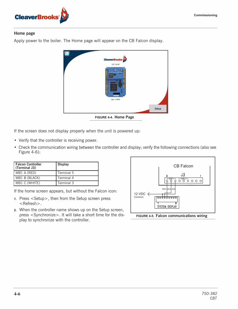
Home page
Apply power to the boiler. The Home page will appear on the CB Falcon display.
If the screen does not display properly when the unit is powered up:
• Verify that the controller is receiving power.
• Check the communication wiring between the controller and display; verify the following connections (also see Figure 4-6):
If the home screen appears, but without the Falcon icon:
1. Press <Setup>, then from the Setup screen press <Refresh>.
2. When the controller name shows up on the Setup screen, press <Synchronize>. It will take a short time for the dis-play to synchronize with the controller.
Falcon Controller (Terminal J3)
Display
MB1 A (RED) Terminal 5MB1 B (BLACK) Terminal 4MB1 C (WHITE) Terminal 3
FIGURE 4-4. Home Page
12 VDCCommon
CB Falcon
RED BLK WH
MB1 MB2
FIGURE 4-5. Falcon communications wiring
4-6 750-382CBT
Commissioning
Display setup
Starting from the Home screen, press <Setup> then <Display Setup> for the Display Setup menu.
The Display Setup menu accesses selections for adjusting and customizing the Falcon display and for basic set-tings of the COM1 and COM2 Modbus ports.
After making changes, press <Save> and cycle power to the controller.
Status page
Pressing the Falcon icon on the Home page takes the user to the Status page, which summarizes boiler statusand allows navigation to the configuration, operational, and diagnostic areas of the CB Falcon interface.
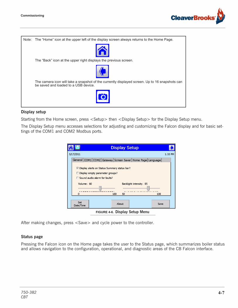
Note: The “Home” icon at the upper left of the display screen always returns to the Home Page.
The “Back” icon at the upper right displays the previous screen.
The camera icon will take a snapshot of the currently displayed screen. Up to 16 snapshots canbe saved and loaded to a USB device.
FIGURE 4-6. Display Setup Menu
750-382CBT
4-7

Commissioning
The Demand display will show one of the following:
Burner enable offOff (burner switch on but no demand)Steam
Burner state shows the currently active step in the burner operating sequence.
The central portion of the display can be toggled between the following:
Pumps shows the status of the pump/auxiliary relay contactsModulation shows fan speed RPM settings for Demand, Limited, and Override ratesSetpoints shows the ON, Modulation, and OFF setpoints.
The History banner is located near the bottom of the screen. Lockouts, Alerts, and Hold conditions will beannunciated here. Pressing the banner allows access to the Lockout and Alert history logs. In the case of alockout alarm, the lockout can be cleared by navigating to the Lockout History and pressing <Clear Lockout>.
The steam pressure modulation setpoints can be changed from the Status page by pressing the currentdisplayed value. A numeric keypad will pop up, allowing entry of new values.
FIGURE 4-7. Status page
Note: Before clearing a lockout, firstident i fy and cor rect thecondition that caused thelockout.
4-8 750-382CBT
Commissioning
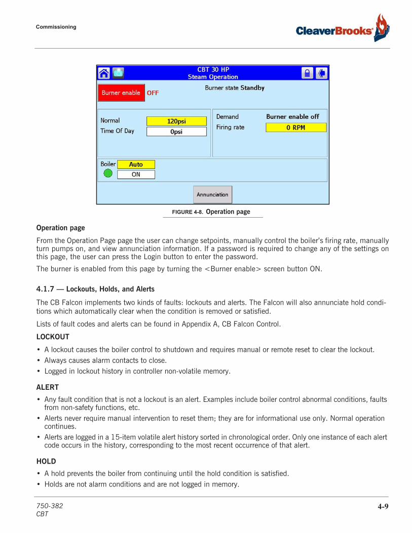
Operation page
From the Operation Page page the user can change setpoints, manually control the boiler’s firing rate, manuallyturn pumps on, and view annunciation information. If a password is required to change any of the settings onthis page, the user can press the Login button to enter the password.
The burner is enabled from this page by turning the <Burner enable> screen button ON.
4.1.7 — Lockouts, Holds, and Alerts
The CB Falcon implements two kinds of faults: lockouts and alerts. The Falcon will also annunciate hold condi-tions which automatically clear when the condition is removed or satisfied.
Lists of fault codes and alerts can be found in Appendix A, CB Falcon Control.
LOCKOUT
• A lockout causes the boiler control to shutdown and requires manual or remote reset to clear the lockout.• Always causes alarm contacts to close.• Logged in lockout history in controller non-volatile memory.
ALERT
• Any fault condition that is not a lockout is an alert. Examples include boiler control abnormal conditions, faults from non-safety functions, etc.
• Alerts never require manual intervention to reset them; they are for informational use only. Normal operation continues.
• Alerts are logged in a 15-item volatile alert history sorted in chronological order. Only one instance of each alert code occurs in the history, corresponding to the most recent occurrence of that alert.
HOLD
• A hold prevents the boiler from continuing until the hold condition is satisfied.• Holds are not alarm conditions and are not logged in memory.
FIGURE 4-8. Operation page
750-382CBT
4-9
Commissioning
See also Chapter 5, Section E - Troubleshooting.
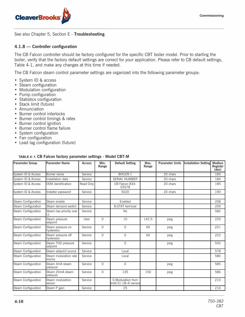
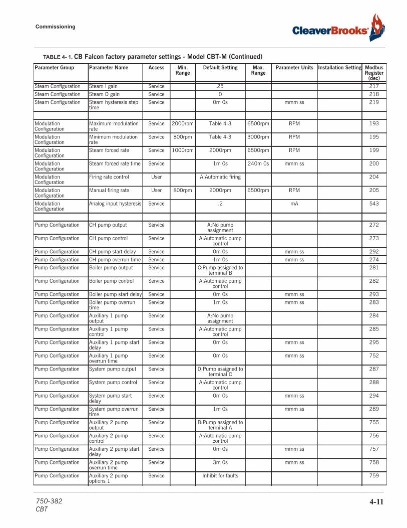
4.1.8 — Controller configuration
The CB Falcon controller should be factory configured for the specific CBT boiler model. Prior to starting the boiler, verify that the factory default settings are correct for your application. Please refer to CB default settings, Table 4-1, and make any changes at this time if needed.
The CB Falcon steam control parameter settings are organized into the following parameter groups:
• System ID & access• Steam configuration• Modulation configuration• Pump configuration• Statistics configuration• Stack limit (future)• Annunciation• Burner control interlocks• Burner control timings & rates• Burner control ignition• Burner control flame failure• System configuration• Fan configuration• Lead lag configuration (future)
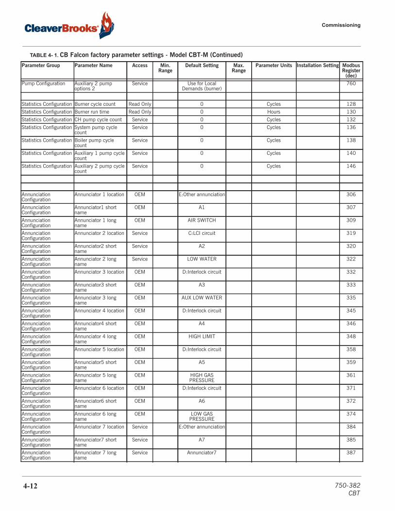
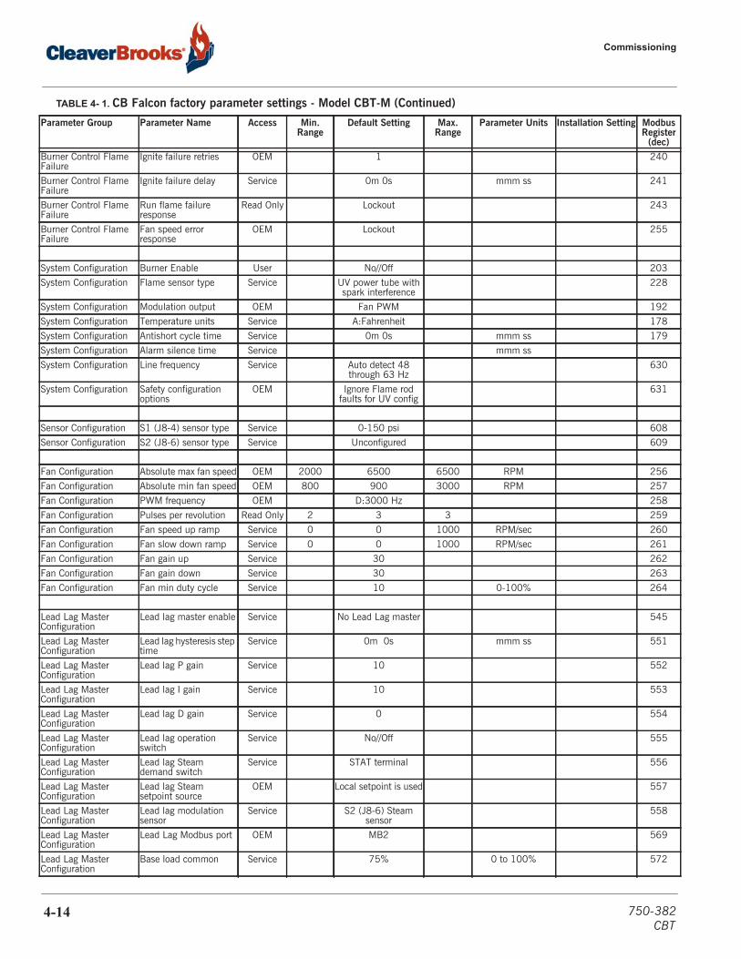
TABLE 4- 1. CB Falcon factory parameter settings - Model CBT-M
Parameter Group Parameter Name Access Min. Range
Default Setting Max. Range
Parameter Units Installation Setting Modbus Register
(dec)System ID & Access Burner name Service BOILER 1 20 chars 183
System ID & Access Installation data Service SERIAL NUMBER 20 chars 184
System ID & Access OEM identification Read Only CB Falcon 833-03578
20 chars 185
System ID & Access Installer password Service 9220 20 chars 190
Steam Configuration Steam enable Service Enabled 208
Steam Configuration Steam demand switch Service B:STAT terminal 209
Steam Configuration Steam has priority over LL
Service No 582
Steam Configuration Steam pressure setpoint
User 0 10 142.5 psig 220
Steam Configuration Steam pressure on hysteresis
Service 0 0 60 psig 221
Steam Configuration Steam pressure off hysteresis
Service 0 6 60 psig 222
Steam Configuration Steam TOD pressure setpoint
Service 0 psig 542
Steam Configuration Steam setpoint source Service Local 578
Steam Configuration Steam modulation rate source
Service Local 580
Steam Configuration Steam 4mA steam pressure
Service 0 0 psig 585
Steam Configuration Steam 20mA steam pressure
Service 0 135 150 psig 586
Steam Configuration Steam modulation sensor
Service C:Modulation from Inlet S1 (J8-4) sensor
210
Steam Configuration Steam P gain Service 25 216
4-10 750-382CBT
Commissioning
Steam Configuration Steam I gain Service 25 217
Steam Configuration Steam D gain Service 0 218
Steam Configuration Steam hysteresis step time
Service 0m 0s mmm ss 219
Modulation Configuration
Maximum modulation rate
Service 2000rpm Table 4-3 6500rpm RPM 193
Modulation Configuration
Minimum modulation rate
Service 800rpm Table 4-3 3000rpm RPM 195
Modulation Configuration
Steam forced rate Service 1000rpm 2000rpm 6500rpm RPM 199
Modulation Configuration
Steam forced rate time Service 1m 0s 240m 0s mmm ss 200
Modulation Configuration
Firing rate control User A:Automatic firing 204
Modulation Configuration
Manual firing rate User 800rpm 2000rpm 6500rpm RPM 205
Modulation Configuration
Analog input hysteresis Service .2 mA 543
Pump Configuration CH pump output Service A:No pump assignment
272
Pump Configuration CH pump control Service A:Automatic pump control
273
Pump Configuration CH pump start delay Service 0m 0s mmm ss 292
Pump Configuration CH pump overrun time Service 1m 0s mmm ss 274
Pump Configuration Boiler pump output Service C:Pump assigned to terminal B
281
Pump Configuration Boiler pump control Service A:Automatic pump control
282
Pump Configuration Boiler pump start delay Service 0m 0s mmm ss 293
Pump Configuration Boiler pump overrun time
Service 1m 0s mmm ss 283
Pump Configuration Auxiliary 1 pump output
Service A:No pump assignment
284
Pump Configuration Auxiliary 1 pump control
Service A:Automatic pump control
285
Pump Configuration Auxiliary 1 pump start delay
Service 0m 0s mmm ss 295
Pump Configuration Auxiliary 1 pump overrun time
Service 0m 0s mmm ss 752
Pump Configuration System pump output Service D:Pump assigned to terminal C
287
Pump Configuration System pump control Service A:Automatic pump control
288
Pump Configuration System pump start delay
Service 0m 0s mmm ss 294
Pump Configuration System pump overrun time
Service 1m 0s mmm ss 289
Pump Configuration Auxiliary 2 pump output
Service B:Pump assigned to terminal A
755
Pump Configuration Auxiliary 2 pump control
Service A:Automatic pump control
756
Pump Configuration Auxiliary 2 pump start delay
Service 0m 0s mmm ss 757
Pump Configuration Auxiliary 2 pump overrun time
Service 3m 0s mmm ss 758
Pump Configuration Auxiliary 2 pump options 1
Service Inhibit for faults 759
TABLE 4- 1. CB Falcon factory parameter settings - Model CBT-M (Continued)
Parameter Group Parameter Name Access Min. Range
Default Setting Max. Range
Parameter Units Installation Setting Modbus Register
(dec)
750-382CBT
4-11
Commissioning
Pump Configuration Auxiliary 2 pump options 2
Service Use for Local Demands (burner)
760
Statistics Configuration Burner cycle count Read Only 0 Cycles 128
Statistics Configuration Burner run time Read Only 0 Hours 130
Statistics Configuration CH pump cycle count Service 0 Cycles 132
Statistics Configuration System pump cycle count
Service 0 Cycles 136
Statistics Configuration Boiler pump cycle count
Service 0 Cycles 138
Statistics Configuration Auxiliary 1 pump cycle count
Service 0 Cycles 140
Statistics Configuration Auxiliary 2 pump cycle count
Service 0 Cycles 146
Annunciation Configuration
Annunciator 1 location OEM E:Other annunciation 306
Annunciation Configuration
Annunciator1 short name
OEM A1 307
Annunciation Configuration
Annunciator 1 long name
OEM AIR SWITCH 309
Annunciation Configuration
Annunciator 2 location Service C:LCI circuit 319
Annunciation Configuration
Annunciator2 short name
Service A2 320
Annunciation Configuration
Annunciator 2 long name
Service LOW WATER 322
Annunciation Configuration
Annunciator 3 location OEM D:Interlock circuit 332
Annunciation Configuration
Annunciator3 short name
OEM A3 333
Annunciation Configuration
Annunciator 3 long name
OEM AUX LOW WATER 335
Annunciation Configuration
Annunciator 4 location OEM D:Interlock circuit 345
Annunciation Configuration
Annunciator4 short name
OEM A4 346
Annunciation Configuration
Annunciator 4 long name
OEM HIGH LIMIT 348
Annunciation Configuration
Annunciator 5 location OEM D:Interlock circuit 358
Annunciation Configuration
Annunciator5 short name
OEM A5 359
Annunciation Configuration
Annunciator 5 long name
OEM HIGH GAS PRESSURE
361
Annunciation Configuration
Annunciator 6 location OEM D:Interlock circuit 371
Annunciation Configuration
Annunciator6 short name
OEM A6 372
Annunciation Configuration
Annunciator 6 long name
OEM LOW GAS PRESSURE
374
Annunciation Configuration
Annunciator 7 location Service E:Other annunciation 384
Annunciation Configuration
Annunciator7 short name
Service A7 385
Annunciation Configuration
Annunciator 7 long name
Service Annunciator7 387
TABLE 4- 1. CB Falcon factory parameter settings - Model CBT-M (Continued)
Parameter Group Parameter Name Access Min. Range
Default Setting Max. Range
Parameter Units Installation Setting Modbus Register
(dec)
4-12 750-382CBT
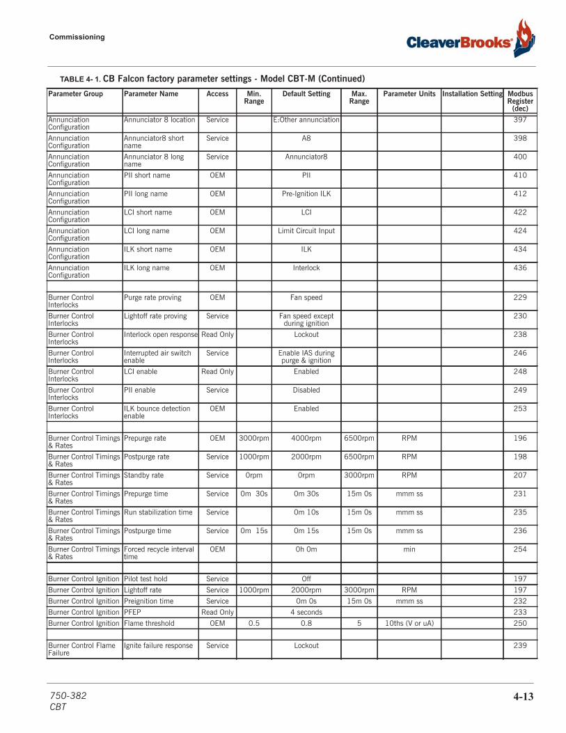
Commissioning
Annunciation Configuration
Annunciator 8 location Service E:Other annunciation 397
Annunciation Configuration
Annunciator8 short name
Service A8 398
Annunciation Configuration
Annunciator 8 long name
Service Annunciator8 400
Annunciation Configuration
PII short name OEM PII 410
Annunciation Configuration
PII long name OEM Pre-Ignition ILK 412
Annunciation Configuration
LCI short name OEM LCI 422
Annunciation Configuration
LCI long name OEM Limit Circuit Input 424
Annunciation Configuration
ILK short name OEM ILK 434
Annunciation Configuration
ILK long name OEM Interlock 436
Burner Control Interlocks
Purge rate proving OEM Fan speed 229
Burner Control Interlocks
Lightoff rate proving Service Fan speed except during ignition
230
Burner Control Interlocks
Interlock open response Read Only Lockout 238
Burner Control Interlocks
Interrupted air switch enable
Service Enable IAS during purge & ignition
246
Burner Control Interlocks
LCI enable Read Only Enabled 248
Burner Control Interlocks
PII enable Service Disabled 249
Burner Control Interlocks
ILK bounce detection enable
OEM Enabled 253
Burner Control Timings & Rates
Prepurge rate OEM 3000rpm 4000rpm 6500rpm RPM 196
Burner Control Timings & Rates
Postpurge rate Service 1000rpm 2000rpm 6500rpm RPM 198
Burner Control Timings & Rates
Standby rate Service 0rpm 0rpm 3000rpm RPM 207
Burner Control Timings & Rates
Prepurge time Service 0m 30s 0m 30s 15m 0s mmm ss 231
Burner Control Timings & Rates
Run stabilization time Service 0m 10s 15m 0s mmm ss 235
Burner Control Timings & Rates
Postpurge time Service 0m 15s 0m 15s 15m 0s mmm ss 236
Burner Control Timings & Rates
Forced recycle interval time
OEM 0h 0m min 254
Burner Control Ignition Pilot test hold Service Off 197
Burner Control Ignition Lightoff rate Service 1000rpm 2000rpm 3000rpm RPM 197
Burner Control Ignition Preignition time Service 0m 0s 15m 0s mmm ss 232
Burner Control Ignition PFEP Read Only 4 seconds 233
Burner Control Ignition Flame threshold OEM 0.5 0.8 5 10ths (V or uA) 250
Burner Control Flame Failure
Ignite failure response Service Lockout 239
TABLE 4- 1. CB Falcon factory parameter settings - Model CBT-M (Continued)
Parameter Group Parameter Name Access Min. Range
Default Setting Max. Range
Parameter Units Installation Setting Modbus Register
(dec)
750-382CBT
4-13
Commissioning
Burner Control Flame Failure
Ignite failure retries OEM 1 240
Burner Control Flame Failure
Ignite failure delay Service 0m 0s mmm ss 241
Burner Control Flame Failure
Run flame failure response
Read Only Lockout 243
Burner Control Flame Failure
Fan speed error response
OEM Lockout 255
System Configuration Burner Enable User No//Off 203
System Configuration Flame sensor type Service UV power tube with spark interference
228
System Configuration Modulation output OEM Fan PWM 192
System Configuration Temperature units Service A:Fahrenheit 178
System Configuration Antishort cycle time Service 0m 0s mmm ss 179
System Configuration Alarm silence time Service mmm ss
System Configuration Line frequency Service Auto detect 48 through 63 Hz
630
System Configuration Safety configuration options
OEM Ignore Flame rod faults for UV config
631
Sensor Configuration S1 (J8-4) sensor type Service 0-150 psi 608
Sensor Configuration S2 (J8-6) sensor type Service Unconfigured 609
Fan Configuration Absolute max fan speed OEM 2000 6500 6500 RPM 256
Fan Configuration Absolute min fan speed OEM 800 900 3000 RPM 257
Fan Configuration PWM frequency OEM D:3000 Hz 258
Fan Configuration Pulses per revolution Read Only 2 3 3 259
Fan Configuration Fan speed up ramp Service 0 0 1000 RPM/sec 260
Fan Configuration Fan slow down ramp Service 0 0 1000 RPM/sec 261
Fan Configuration Fan gain up Service 30 262
Fan Configuration Fan gain down Service 30 263
Fan Configuration Fan min duty cycle Service 10 0-100% 264
Lead Lag Master Configuration
Lead lag master enable Service No Lead Lag master 545
Lead Lag Master Configuration
Lead lag hysteresis step time
Service 0m 0s mmm ss 551
Lead Lag Master Configuration
Lead lag P gain Service 10 552
Lead Lag Master Configuration
Lead lag I gain Service 10 553
Lead Lag Master Configuration
Lead lag D gain Service 0 554
Lead Lag Master Configuration
Lead lag operation switch
Service No//Off 555
Lead Lag Master Configuration
Lead lag Steam demand switch
Service STAT terminal 556
Lead Lag Master Configuration
Lead lag Steam setpoint source
OEM Local setpoint is used 557
Lead Lag Master Configuration
Lead lag modulation sensor
Service S2 (J8-6) Steam sensor
558
Lead Lag Master Configuration
Lead Lag Modbus port OEM MB2 569
Lead Lag Master Configuration
Base load common Service 75% 0 to 100% 572
TABLE 4- 1. CB Falcon factory parameter settings - Model CBT-M (Continued)
Parameter Group Parameter Name Access Min. Range
Default Setting Max. Range
Parameter Units Installation Setting Modbus Register
(dec)
4-14 750-382CBT

Commissioning
Lead Lag Master Configuration
Lead selection method Service Sequence order 574
Lead Lag Master Configuration
Lag selection method Service Sequence order 575
Lead Lag Master Configuration
Lead lag add stage method 1
Service Firing rate threshold to add stage
714
Lead Lag Master Configuration
Lead lag add stage detection time 1
Service 2m 0s mmm ss 716
Lead Lag Master Configuration
Lead lag add stage rate offset
Service 0% -100% to 100% 719
Lead Lag Master Configuration
Lead lag add stage interstage delay
Service 3m 0s mmm ss 722
Lead Lag Master Configuration
Lead lag drop stage method 1
Service Firing rate to drop stage
723
Lead Lag Master Configuration
Lead lag drop stage detection time 1
Service 1m 0s mmm ss 725
Lead Lag Master Configuration
Lead lag drop stage rate offset
Service -3% -100% to 100% 728
Lead Lag Master Configuration
Lead lag drop stage interstage delay
Service 3m 0s mmm ss 731
Lead Lag Master Configuration
Lead rotation time Service 120h 0m min 733
Lead Lag Master Configuration
Force lead rotation time Service 168h 0m min 734
Lead Lag Master Configuration
Lead lag pressure setpoint
User 0 10 135 psig 738
Lead Lag Master Configuration
Lead lag pressure TOD setpoint
Service 0 psig 739
Lead Lag Master Configuration
Lead lag pressure on hysteresis
Service 0 psig 740
Lead Lag Master Configuration
Lead lag pressure off hysteresis
Service 6 psig 741
Lead Lag Master Configuration
Lead lag add stage pressure error threshold
Service 3 psig 742
Lead Lag Master Configuration
Lead lag drop stage pressure error threshold
Service 3 psig 743
Lead Lag Master Configuration
Lead lag 4 mA steam pressure
Service 0 0 psig 745
Lead Lag Master Configuration
Lead lag 20 mA steam pressure
Service 0 135 150 psig 746
Lead Lag Slave Configuration
Lead lag slave enable Service Disabled 544
Lead Lag Slave Configuration
Slave mode Service Equalize runtime 564
Lead Lag Slave Configuration
Base load rate Service 3000rpm RPM 566
Lead Lag Slave Configuration
Fan during off cycle rate Service 0rpm 0rpm 4000rpm RPM 567
Lead Lag Slave Configuration
Slave sequence order Service 0 1 to 8 568
Lead Lag Slave Configuration
Lead lag slave demand to firing delay
Service 3m 0s mmm ss 570
Lead Lag Slave Configuration
Modbus address Service 1 1 to 8 568
TABLE 4- 1. CB Falcon factory parameter settings - Model CBT-M (Continued)
Parameter Group Parameter Name Access Min. Range
Default Setting Max. Range
Parameter Units Installation Setting Modbus Register
(dec)
750-382CBT
4-15
Commissioning
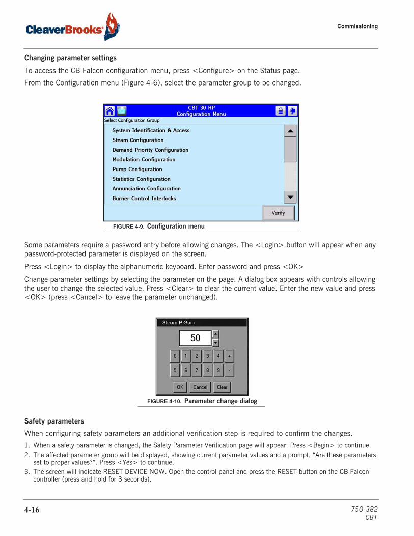
Changing parameter settings
To access the CB Falcon configuration menu, press <Configure> on the Status page.
From the Configuration menu (Figure 4-6), select the parameter group to be changed.
Some parameters require a password entry before allowing changes. The <Login> button will appear when any password-protected parameter is displayed on the screen.
Press <Login> to display the alphanumeric keyboard. Enter password and press <OK>
Change parameter settings by selecting the parameter on the page. A dialog box appears with controls allowing the user to change the selected value. Press <Clear> to clear the current value. Enter the new value and press <OK> (press <Cancel> to leave the parameter unchanged).
Safety parameters
When configuring safety parameters an additional verification step is required to confirm the changes.
1. When a safety parameter is changed, the Safety Parameter Verification page will appear. Press <Begin> to continue.2. The affected parameter group will be displayed, showing current parameter values and a prompt, “Are these parameters
set to proper values?”. Press <Yes> to continue.3. The screen will indicate RESET DEVICE NOW. Open the control panel and press the RESET button on the CB Falcon
controller (press and hold for 3 seconds).
FIGURE 4-9. Configuration menu
FIGURE 4-10. Parameter change dialog
4-16 750-382CBT
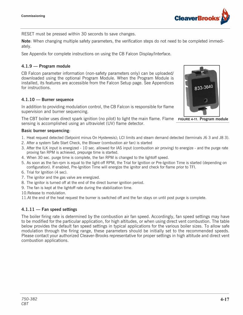
Commissioning
RESET must be pressed within 30 seconds to save changes.
Note: When changing multiple safety parameters, the verification steps do not need to be completed immedi-ately.
See Appendix for complete instructions on using the CB Falcon Display/Interface.
4.1.9 — Program module
CB Falcon parameter information (non-safety parameters only) can be uploaded/downloaded using the optional Program Module. When the Program Module isinstalled, its features are accessible from the Falcon Setup page. See Appendicesfor instructions.
4.1.10 — Burner sequence
In addition to providing modulation control, the CB Falcon is responsible for flamesupervision and burner sequencing.
The CBT boiler uses direct spark ignition (no pilot) to light the main flame. Flamesensing is accomplished using an ultraviolet (UV) flame detector.
Basic burner sequencing:
1. Heat request detected (Setpoint minus On Hysteresis); LCI limits and steam demand detected (terminals J6 3 and J8 3).2. After a system Safe Start Check, the Blower (combustion air fan) is started3. After the ILK input is energized - 10 sec. allowed for IAS input (combustion air proving) to energize - and the purge rate
proving fan RPM is achieved, prepurge time is started. 4. When 30 sec. purge time is complete, the fan RPM is changed to the lightoff speed.5. As soon as the fan-rpm is equal to the light-off RPM, the Trial for Ignition or Pre-Ignition Time is started (depending on
configuration). If enabled, Pre-Ignition Time will energize the ignitor and check for flame prior to TFI.6. Trial for Ignition (4 sec).7. The ignitor and the gas valve are energized.8. The ignitor is turned off at the end of the direct burner ignition period. 9. The fan is kept at the lightoff rate during the stabilization time.10.Release to modulation.11.At the end of the heat request the burner is switched off and the fan stays on until post purge is complete.
4.1.11 — Fan speed settings
The boiler firing rate is determined by the combustion air fan speed. Accordingly, fan speed settings may haveto be modified for the particular application, for high altitudes, or when using direct vent combustion. The tablebelow provides the default fan speed settings in typical applications for the various boiler sizes. To allow safemodulation through the firing range, these parameters should be initially set to the recommended speeds.Please contact your authorized Cleaver-Brooks representative for proper settings in high altitude and direct ventcombustion applications.
FIGURE 4-11. Program module
750-382CBT
4-17
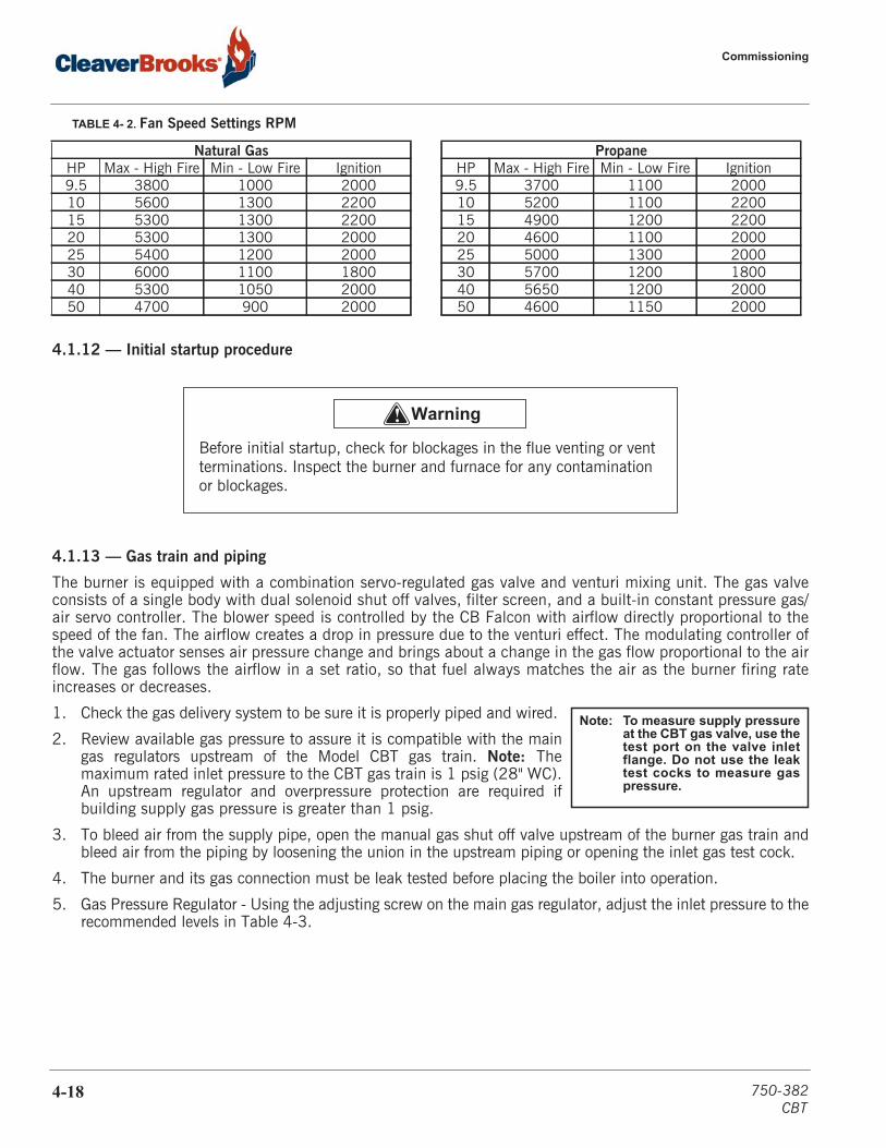
Commissioning
TABLE 4- 2. Fan Speed Settings RPM
4.1.12 — Initial startup procedure
4.1.13 — Gas train and piping
The burner is equipped with a combination servo-regulated gas valve and venturi mixing unit. The gas valveconsists of a single body with dual solenoid shut off valves, filter screen, and a built-in constant pressure gas/air servo controller. The blower speed is controlled by the CB Falcon with airflow directly proportional to thespeed of the fan. The airflow creates a drop in pressure due to the venturi effect. The modulating controller ofthe valve actuator senses air pressure change and brings about a change in the gas flow proportional to the airflow. The gas follows the airflow in a set ratio, so that fuel always matches the air as the burner firing rateincreases or decreases.
1. Check the gas delivery system to be sure it is properly piped and wired.
2. Review available gas pressure to assure it is compatible with the maingas regulators upstream of the Model CBT gas train. Note: Themaximum rated inlet pressure to the CBT gas train is 1 psig (28" WC).An upstream regulator and overpressure protection are required ifbuilding supply gas pressure is greater than 1 psig.
3. To bleed air from the supply pipe, open the manual gas shut off valve upstream of the burner gas train andbleed air from the piping by loosening the union in the upstream piping or opening the inlet gas test cock.
4. The burner and its gas connection must be leak tested before placing the boiler into operation.
5. Gas Pressure Regulator - Using the adjusting screw on the main gas regulator, adjust the inlet pressure to therecommended levels in Table 4-3.
Natural Gas PropaneHP Max - High Fire Min - Low Fire Ignition HP Max - High Fire Min - Low Fire Ignition9.5 3800 1000 2000 9.5 3700 1100 200010 5600 1300 2200 10 5200 1100 220015 5300 1300 2200 15 4900 1200 220020 5300 1300 2000 20 4600 1100 200025 5400 1200 2000 25 5000 1300 200030 6000 1100 1800 30 5700 1200 180040 5300 1050 2000 40 5650 1200 200050 4700 900 2000 50 4600 1150 2000
! Warning
Before initial startup, check for blockages in the flue venting or vent terminations. Inspect the burner and furnace for any contamination or blockages.
Note: To measure supply pressureat the CBT gas valve, use thetest port on the valve inletflange. Do not use the leaktest cocks to measure gaspressure.
4-18 750-382CBT

Commissioning
*Maximum pressure without the use of an upstream regulator.
4.1.14 — Power-up
1. Ensure blower motor is properly wired for the available power supply.
2. Verify the voltage (control voltage is 115V-1Ph.-50/60Hz) to ensure it is within specifications.
3. To power the control and blower circuits, the CC-Blower switch to the “ON” position.
4. When the control and blower circuits are powered, commissioning may begin. Turn the Demand switch to the “LOC”(Local) position. On the Operation page, the Demand status should indicate “Steam”. The boiler will now start if the LCIand ILK circuits are satisfied and the steam pressure is below the current On point.
4.1.15 — Operation check: gas valve, gas pressure switches, and combustion air proving switch
Before initial firing of the burner, the gas valve, Low Gas Pressure Switch (LGPS), High Gas Pressure Switch(HGPS), and Combustion Air Proving Switch (CAPS) should be checked for proper operation.
• Before proceeding, review Section 4.3 - Control setpoints for initial LGPS, HGPS, and CAPS settings.
Note: Close the downstream manual gas shut-off valve before checking pressure switches and CAPS.
TABLE 4- 3. CBT Gas Pressure Requirements
CBT Size Natural Gas LP GasMin (“WC) Max (“WC)* Min (“WC) Max (“WC)*
9.5 7 14 11 1410 7 14 11 1415 7 14 11 1420 7 14 11 1425 7 14 11 1430 11 14 11 1440 11 14 11 1450 11 14 11 14
FIGURE 4-12. Premix burner technology - full modulation
750-382CBT
4-19

Commissioning
While performing the following safety checks, use the CB Falcon Annunciation screen to monitor the status ofthe circuits involved. Press <Annunciation> on the Operation page to access this screen.
LGPS
1. To check the Low Gas Pressure Switch, first close the upstream manual shutoff valve (both manual shutoffvalves should now be closed).
2. Start the burner and wait 10 seconds during purge for CAPS to be made.3. Turn the LGPS setting to maximum.4. Open the test cock to bleed the gas line.5. The controller should lock out. The screen will indicate Lockout 67 ILK OFF.6. Reset the controller and change the LGPS setting back to minimum to proceed.
CAPS (Interrupted Airflow Switch)
1. Initiate burner sequence. 2. During purge cycle, set Combustion Air Proving Switch to its maximum setting. 3. The CB Falcon should lock out on an airflow failure. The display will show Lockout 65 Interrupted Airflow
Switch OFF.
Note: If the CAPS fails to open even when set to maximum, test by disconnecting the low-pressure line to the switch and initiating burner sequence. The switch should now break during the purge cycle. Reconnect low-pres-sure side after a successful CAPS check.
4. Following a successful CAPS check, dial the CAPS back to its minimum setting and reset the CB Falcon.
Note: The CAPS is ignored when the boiler is in “Run” state. A CAPS test must be performed during Purge or Trial for Ignition.
HGPS and GAS VALVE
1. Open the upstream manual shutoff valve and wait a few moments for gas pressure to rise.2. Lower the switch setting to minimum.3. Initiate burner sequence. During the main flame establishing period, verify gas valve LEDs energize, indicating
both safety shutoff valves open.4. The CB Falcon should lock out on an interlock failure (Lockout 67).5. Reset CB Falcon.6. Open the downstream manual shutoff valve to clear the lockout condition.7. Dial the HGPS back to its maximum setting and reset.
FIGURE 4-13. Annunciation screen
4-20 750-382CBT
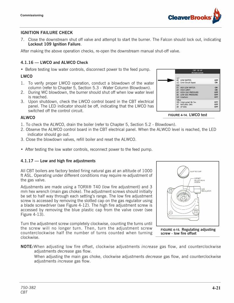
Commissioning
IGNITION FAILURE CHECK
7. Close the downstream shut off valve and attempt to start the burner. The Falcon should lock out, indicatingLockout 109 Ignition Failure.
After making the above operation checks, re-open the downstream manual shut-off valve.
4.1.16 — LWCO and ALWCO Check
• Before testing low water controls, disconnect power to the feed pump.
LWCO
1. To verify proper LWCO operation, conduct a blowdown of the watercolumn (refer to Chapter 5, Section 5.3 - Water Column Blowdown).
2. During WC blowdown, the burner should shut off when low water levelis reached.
3. Upon shutdown, check the LWCO control board in the CBT electricalpanel. The LED indicator should be off, indicating that the LWCO hasswitched off the control circuit.
ALWCO
1. To check the ALWCO, drain the boiler (refer to Chapter 5, Section 5.2 - Blowdown).2. Observe the ALWCO control board in the CBT electrical panel. When the ALWCO level is reached, the LED
indicator should go out.3. Close the blowdown valves, refill boiler and reset the ALWCO.
• After testing the low water controls, reconnect power to the feed pump.
4.1.17 — Low and high fire adjustments
All CBT boilers are factory tested firing natural gas at an altitude of 1000ft ASL. Operating under different conditions may require re-adjustment ofthe gas valve.
Adjustments are made using a TORX® T40 (low fire adjustment) and 3mm hex wrench (main gas choke). The adjustment screws should initiallybe set to half way through each setting’s range. The low fire adjustmentscrew is accessed by removing the slotted cap on the gas regulator usinga blade screwdriver (see Figure 4-12). The high fire adjustment screw isaccessed by removing the blue plastic cap from the valve cover (seeFigure 4-13).
Turn the adjustment screw completely clockwise, counting the turns untilthe screw will no longer turn. Then, turn the adjustment screwcounterclockwise half the number of turns counted when turningclockwise.
NOTE:When adjusting low fire offset, clockwise adjustments increase gas flow, and counterclockwiseadjustments decrease gas flow.When adjusting the main gas choke, clockwise adjustments decrease gas flow, and counterclockwiseadjustments increase gas flow.
FIGURE 4-14. LWCO test
FIGURE 4-15. Regulating adjusting screw - low fire offset
750-382CBT
4-21
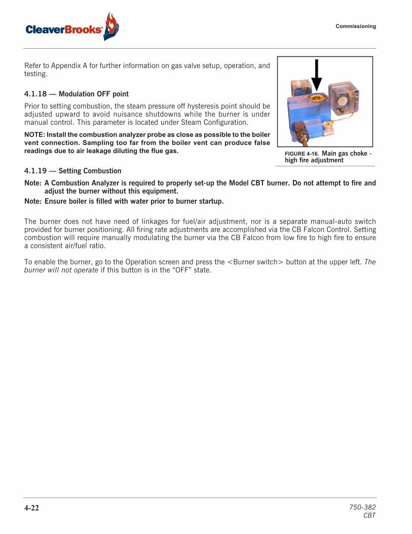
Commissioning
Refer to Appendix A for further information on gas valve setup, operation, andtesting.
4.1.18 — Modulation OFF point
Prior to setting combustion, the steam pressure off hysteresis point should beadjusted upward to avoid nuisance shutdowns while the burner is undermanual control. This parameter is located under Steam Configuration.
NOTE: Install the combustion analyzer probe as close as possible to the boilervent connection. Sampling too far from the boiler vent can produce falsereadings due to air leakage diluting the flue gas.
4.1.19 — Setting Combustion
Note: A Combustion Analyzer is required to properly set-up the Model CBT burner. Do not attempt to fire andadjust the burner without this equipment.
Note: Ensure boiler is filled with water prior to burner startup.
The burner does not have need of linkages for fuel/air adjustment, nor is a separate manual-auto switchprovided for burner positioning. All firing rate adjustments are accomplished via the CB Falcon Control. Settingcombustion will require manually modulating the burner via the CB Falcon from low fire to high fire to ensurea consistent air/fuel ratio.
To enable the burner, go to the Operation screen and press the <Burner switch> button at the upper left. Theburner will not operate if this button is in the “OFF” state.
FIGURE 4-16. Main gas choke - high fire adjustment
4-22 750-382CBT
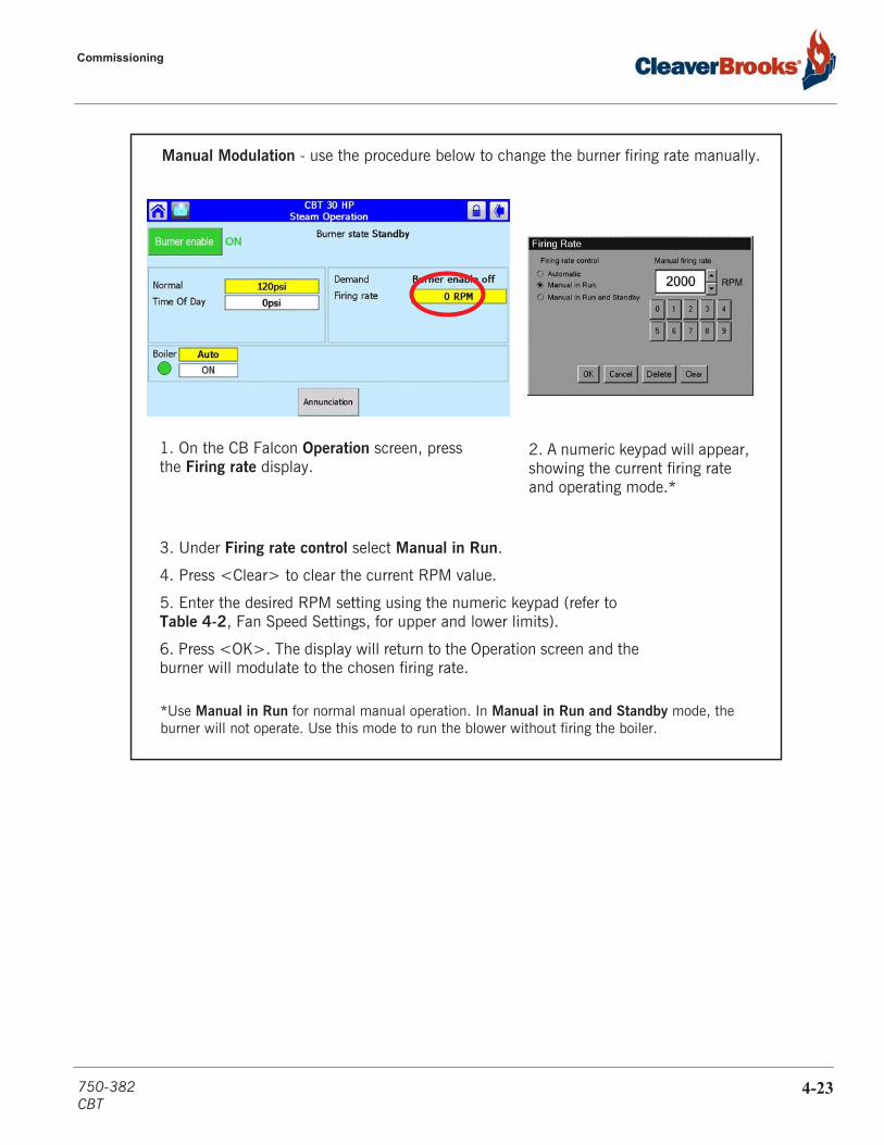
Commissioning
1. On the CB Falcon Operation screen, press the Firing rate display.
2. A numeric keypad will appear, showing the current firing rate and operating mode.*
3. Under Firing rate control select Manual in Run.
4. Press <Clear> to clear the current RPM value.
5. Enter the desired RPM setting using the numeric keypad (refer to Table 4-2, Fan Speed Settings, for upper and lower limits).
6. Press <OK>. The display will return to the Operation screen and the burner will modulate to the chosen firing rate.
Manual Modulation - use the procedure below to change the burner firing rate manually.
*Use Manual in Run for normal manual operation. In Manual in Run and Standby mode, the burner will not operate. Use this mode to run the blower without firing the boiler.
750-382CBT
4-23
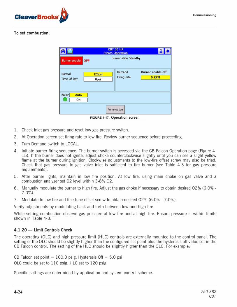
Commissioning
To set combustion:
1. Check inlet gas pressure and reset low gas pressure switch.
2. At Operation screen set firing rate to low fire. Review burner sequence before proceeding.
3. Turn Demand switch to LOCAL.
4. Initiate burner firing sequence. The burner switch is accessed via the CB Falcon Operation page (Figure 4-15). If the burner does not ignite, adjust choke counterclockwise slightly until you can see a slight yellowflame at the burner during ignition. Clockwise adjustments to the low-fire offset screw may also be tried.Check that gas pressure to gas valve inlet is sufficient to fire burner (see Table 4-3 for gas pressurerequirements).
5. After burner lights, maintain in low fire position. At low fire, using main choke on gas valve and acombustion analyzer set O2 level within 3-8% O2.
6. Manually modulate the burner to high fire. Adjust the gas choke if necessary to obtain desired O2% (6.0% -7.0%).
7. Modulate to low fire and fine tune offset screw to obtain desired O2% (6.0% - 7.0%).
Verify adjustments by modulating back and forth between low and high fire.
While setting combustion observe gas pressure at low fire and at high fire. Ensure pressure is within limitsshown in Table 4-3.
4.1.20 — Limit Controls Check
The operating (OLC) and high pressure limit (HLC) controls are externally mounted to the control panel. Thesetting of the OLC should be slightly higher than the configured set point plus the hysteresis off value set in theCB Falcon control. The setting of the HLC should be slightly higher than the OLC. For example:
CB Falcon set point = 100.0 psig, Hysteresis Off = 5.0 psiOLC could be set to 110 psig, HLC set to 120 psig
Specific settings are determined by application and system control scheme.
FIGURE 4-17. Operation screen
4-24 750-382CBT

Boil-out of a new unit
The OLC and HLC can be tested while the boiler is producing steam by adjusting the switch setting downward.A lockout should result when the switch setting is at or just below the current steam pressure.
Readjust each switch (and reset HLC) after testing.
4.2 — Boil-out of a new unit
The inside of a new boiler may contain oil, grease, or other contaminants which, if not removed, could adverselyaffect system performance. New units should be cleaned by boil-out before use.Recommended boil-out procedure is as follows:1. Determine boiler water capacity (see Table 4-4). Have sufficient cleaning material on hand to complete the
job.
2. When dissolving dry chemicals, slowly introduce the chemical into warm water in a suitable container. Stirconstantly until the chemical is completely dissolved.
3. An over-flow pipe should be attached to one of the top boiler openings and routed to a safe point ofdischarge. A relief or safety valve tapping is normally used for this purpose.
4. Water relief valves and steam safety valves must be removed before adding the boilout solution to avoidcontaminating the valves. Use caution when removing and reinstalling these devices.
5. All valves in the piping leading to or from the system must be closed to prevent cleaning solution from gettinginto the system.
6. Fill the boiler vessel with enough clean water to cover the furnace. Add the cleaning solution, then fill to thetop. The water used in the initial fill should be at ambient temperature.
7. Fire the boiler intermittently so as to hold solution just at the boiling point. Boil for at least five hours. Do notproduce steam pressure.
8. Allow a small amount of fresh water into the boiler. This will create a slight overflow that will carry offsurface impurities.
9. Continue the boil and overflow process until the water clears. Shut the burner down.
10. Let the boiler cool to 120o F or less.
11. Drain the boiler, remove hand-hole plates and wash the waterside surfaces thoroughly using a high pressurehose.
12. Inspect the surfaces. If they are not clean, repeat boil-out procedure.
13. After closing the handholes and reinstalling safety or relief valves, fill the boiler and fire it until the water isheated to at least 180o F to drive off any dissolved gases.
*9.5 HP is 100 psig
TABLE 4- 4. Boiler water capacity
Boiler HP 9.5 10 15 20 25 30 40 50
Normal volume (gal)150 psig 33* 54 54 143 143 181 305 305
15 psig - 55 55 136 136 177 298 298
Flooded volume (gal)150 psig 45* 80 80 195 195 244 394 394
15 psig - 82 82 196 196 248 400 400
750-382CBT
4-25

Commissioning
4.3 — Post start-up checkout procedure
1. Set high gas pressure switch to 50% higher than operating gas pressure at low fire. Set low gas pressureswitch to 50% lower than operating gas pressure at low fire.
2. Check the draft on the outlet stack on each boiler, compare to acceptable limits (-.25 to +.25“ W.C.) andrecord in start up form. Operating outside of acceptable limits could result in light off and flame failureproblems.
3. Switch to automatic operation and monitor flue gas to ensure consistent excess air.4. Reassemble all panels and covers that were removed and replace any plugs that were removed to check gas
pressure.5. Verify gas pressures remain within limits shown in Table 4-3.
6. Provide instructions to owner and operators on operation, safety and maintenance of the equipment. 7. Provide instructions to owner and operators on proper water treatment guidelines and procedures.
4.4 — Falcon control functions and customer interface
Following is a brief overview of the Falcon control features on steam boilers. Please refer to the Falcon Controloperating instructions in Appendix A for more detailed explanations.
• Set Point• Time-of-Day (TOD) Set Point• Hysteresis On and Hysteresis Off• PID modulation control• Remote Enable and Remote 4-20mA Input• Remote Modulation• Remote Set Point• Configurable pump/auxiliary relay contacts• Annunciator• Diagnostics• Lockout/Alarm History• Trend Analysis• Modbus communications
Set point, TOD set point, hysteresis on, hysteresis off, and PID load control
The set point is the value that the boiler’s PID load control attempts to maintain in order to meet the steamdemand. The modulating set point can be adjusted at the Operation page or under the Steam Configurationparameter group. No password is required to change the set point. To change the set point at the Operationpage, press the set point value next to “Normal”. Clear the current value and enter the new value. Press <OK>to establish the new set point.
The Time-of-Day (TOD), or setback, set point is an alternative set point that is enabled when a remote contactconnected to terminals J10-2 & J10-3 is closed (Refer to Figure 2-8 CBT Wiring Diagram). When the circuit isopen, the boiler control reverts back to the normal set point. The TOD set point can be adjusted at either theOperation page or under the Steam Configuration parameter group. Service level password login is required tochange this parameter.
4-26 750-382CBT
Falcon control functions and customer interface
The hysteresis on and hysteresis off points can only be changed under the Steam Configuration parameter groupand require a login with the Service level password. Hysteresis on is the differential below the current set pointat which the boiler will restart following an off cycle. Hysteresis off is the differential above the current set pointat which the boiler will cycle off – effectively the boiler’s operating limit. These two parameters apply to boththe normal and TOD set points. To minimize the frequency of cycling the boiler on and off, the values of either,or both, of these settings may be increased. Default settings for Hysteresis on and off are 0 and 3 psi,respectively.
The PID (Proportional-Integral-Derivative) load control operates to generate the demand source’s modulationrate. Under Steam configuration, the PID gain values can be adjusted to match the desired modulationresponse. The default gain value settings of P=50, I=50 & D=0 have proven to work well with typical steamboiler applications.
Remote enable and remote 4-20mA input
Remote enable and Remote 4-20mA input allow the boiler to be sequenced and/or controlled from a separateboiler room controller or building management system. The 3-position Demand switch at the front of the controlpanel determines whether the boiler is off, in local, or under remote control. When in the “LOC” (local) position,the boiler operates on its own set point and ignores any remote signal connections. When in the “REM” (remote)position, the boiler can be enabled and modulated by remote discrete and analog (4-20mA) inputs, respectively.When in the “OFF” position, the boiler will not operate.
Refer to Figures 2-7 & 2-8, or your specific boiler wiring diagram, for remote enable and remote 4-20mA inputconnections. For simple remote on-off sequencing, only terminals 24 and 25 (Falcon J8-1 & J8-3) need to beconnected to dry enable contacts at the remote controller. When terminal 25 (steam demand input) isenergized, the steam demand is enabled. The boiler operates on its local set point and PID modulating controlsettings.
For remote modulation (firing rate) control, both the remote enable and remote 4-20mA input connections mustbe made. The default setting for the 4-20mA remote input is “Modulation”. This setting should be verified underthe Falcon control’s Steam configuration group, “Steam 4-20mA remote control”. To avoid nuisance operatinglimit shut downs of the boiler, the Falcon’s normal operating set point should be adjusted to a value that isgreater than the system header set point.
With steam demand present and completion of a successful trial for ignition sequence, the boiler will modulateaccording to the 4-20mA input signal provided: 4mA = minimum modulation rate (low fire); 20mA =maximum modulation rate (high fire). The boiler will continue to modulate until the steam demand is removed,the operating limit is reached, LCI is opened (e.g. low water condition), or a Falcon lockout alarm occurs (e.g.ILK opens on a High Limit trip).
To configure the boiler for remote set point control, navigate to the Falcon control’s Steam configuration group.Change the setting of “Steam 4-20mA remote control” to “Set Point”. Next, the span of the 4-20mA needs tobe established. The steam set point determines the value for 20mA; “minimum steam pressure” determines thevalue for 4mA.
Depending on the quality of the remote input signal, the modulation rate or operating set point may fluctuateunnecessarily because of small changes in the measured current signal. Under the Modulation configurationgroup, the “4-20mA input Hysteresis” setting may need to be adjusted to avoid undesired fluctuations in theeither the modulation rate or operating set point. The default setting is 0.1mA and can be increased toessentially filter out small fluctuations of the input signal. It may take some trial and error to establish theoptimum input hysteresis setting for a particular system.
If at any time the remote 4-20mA input signal is disconnected, the Falcon control will indicate “OPEN” underthe 4-20mA input value at the operation screen. The boiler will then operate on its local set point and PIDmodulation control. Once the 4-20mA signal is reestablished, the boiler will resume operation under remotecontrol.
750-382CBT
4-27

Commissioning
4-28 750-382CBT

CHAPTER 5 Maintenance
General 5-2
Bottom blowdown 5-2
Water column blowdown 5-3
Fireside cleaning procedure/disassembly 5-5
Ignition electrode 5-7
UV scanner 5-7
Waterside inspection/cleaning 5-9
Safety valve 5-10
Troubleshooting 5-10
Display diagnostics 5-26
Lay-up 5-26
750-382CBT
5-1

Maintenance
5.1 — General
A well-planned maintenance program will help avoid unnecessary downtime or costly repairs, and will promotesafety and aid boiler inspectors. It is recommended that a boiler room log or record be maintained. Recording ofdaily, weekly, monthly, and yearly maintenance activities will help to obtain economical and lengthy service fromthe equipment.Only trained and authorized personnel should be permitted to operate, adjust, or repair the boiler and relatedequipment. The boiler room should be kept free of all material and equipment not necessary to the operation ofthe boiler or heating system.Be alert to unusual noises, improper gauge readings, leaks, etc. Any leaks - fuel, water, steam, exhaust gas -should be repaired promptly and with attention to safety. Preventive measures, such as regularly checking thetightness of connections, should be included in regular maintenance activities.Insurance regulations and local laws normally require periodic inspection of the pressure vessel by an authorizedinspector. Inspections are usually, though not necessarily, scheduled for periods of normal boiler downtime, suchas an off season. This period can be used to accomplish maintenance, replacement, or repairs that cannot easilybe done at other times.
NOTE: To insure proper operation, use only Cleaver-Brooks parts for replacement.
While the inspection pertains primarily to the waterside and fireside surfaces of the pressure vessel, the inspectionperiod provides operators with an opportunity for a detailed check of all boiler components including piping,valves, gaskets, refractory, etc. Comprehensive cleaning, spot painting, and replacement of expendable itemsshould be planned for and taken care of during this time.Cleaver-Brooks recommends common replacement parts be on hand during inspection and maintenance. Pleaserefer to the Recommended Spare Parts List In the Parts section of this manual.
5.2 — Bottom blowdown
Water treatment alone can never completely eliminate unwanted solids from boiler feedwater. In order to keepthese substances to a minimum, blowdown should be performed at regular intervals.If both a quick-opening and a slow-opening valve are present, the quick-opening valve (the valve nearest theboiler) is opened first and closed last, with blowdown controlled using the slow-opening or downstream valve.Bottom blowdown should be done under a light load and with the water level at the normal operating level.Blowdown should be piped to a blowdown separator.
FIGURE 5-1. Bottom blowdown piping
5-2 750-382CBT

Water column blowdown
It is generally recommended that bottom blowdown be performed at least once in every eight-hour period. Actualfrequency may vary depending on water conditions and boiler operating conditions. Consult the appropriate watertreatment personnel regarding blowdown scheduling.
5.3 — Water column blowdown
Free flow of water through the water column and gauge glass is essential to obtaining accurate boiler water levelindication and control. It is recommended that the water column and gauge glass be blown down every shift toremove accumulated solids. Regular blowdown of the water column will help maintain the integrity of the waterlevel probes and will help to ensure trouble-free operation of the boiler. See Figure 5-2 for procedure.
Manual blowdown procedure
Blowdown is most effective when the boiler is under a light load, and when the water level is at the Normal OperatingWater Level.Be sure the blowdown piping is in proper operating condition. Waste should be piped to a point of safe discharge. To blowdown the boiler:
1. Open the quick-opening valve (one closest to the boiler).2. Open the slow-opening valve.3. Blow down the boiler for the amount of time specified by your water treatment consultant by opening andclosing the slow-opening valve. A minimum of 10 seconds with the valve fully open is recommended.4. Some boilers may require several short blowdown cycles to maintain the proper water level.5. Close the slow-opening valve.6. Close the quick-opening valve.7. Open the slow-opening valve again to drain the line between the quick and slow-opening valves.8. Close the slow-opening valve again and double check that the shutoff is tight after the valve has cooled.
• Never pump the quick-opening valve to blow down the boiler. Such action could cause water hammer and damage the piping and valves. It could also cause personal injury.
• Never leave an open blowdown valve unattended. • Remember the valve closest to the boiler must be opened first. • Blowdown should be done at least once per shift. Depending on operations, more frequent blowdowns may be required.
! Caution
750-382CBT
5-3

Maintenance
Periodic replacement of the water gauge glass should be part of a regular maintenance program. A broken ordiscolored glass should be replaced at once.Use a proper size rubber packing. Do not use loose packing, which could be forced below the glass and possiblyplug the valve opening.
Open
Open
Closed
1 2
3
4
5
6
78
1. Open Water Column blowdown valve (5 to 10 sec.) to discharge water from WC.
2. Close WC blowdown valve.
3. Close upper gauge glass isolation valve.
4. Open gauge glass blowdown valve to discharge water from gauge glass.
5. Close lower gauge glass isolation valve.
6. Open upper gauge glass isolation valve.
7. Open lower gauge glass isolation valve to discharge steam from gauge glass.
8. Close gauge glass blowdown valve.
FIGURE 5-2. Water column and gauge glass blowdown
5-4 750-382CBT
Fireside cleaning procedure/disassembly
Close the valves when replacing the glass. Slip a packing nut, packing washer, and packing ring onto each end ofthe glass. Insert one end of the glass into the upper gauge valve body far enough to allow the lower end to bedropped into the lower body. Slide the packing nuts onto each valve and tighten.It is recommended that the boiler is off and cool when the glass is replaced. However, if the glass is replaced whilethe boiler is in service, open the blowdown valve and slowly bring the glass up to temperature by opening thegauge valves slightly. After the glass is warmed up, close the blowdown valve and open the gauge valvescompletely.
5.4 — Fireside cleaning procedure/disassembly
1. Locate the manual shutoff gas valve for the gas supply to the burner and turn it to the closed or shut position.
2. Disconnect all electrical power to the control panel at the primary switch box or breaker box supplying powerto the boiler.
4. Disconnect power and signal harnesses from blower.
5. Disconnect the ignition cables from the electrodes and unscrew the UV flame detector from its bracket.
6. If using room combustion air, remove air filter. Inspect and replace as necessary.
7. Disconnect the burner gas train from the gas supply piping.
8. Unscrew the nuts (4) securing the blower adapter plate to the dry oven assembly.
9. The blower motor and assembly can now be removed, providing access to the burner head and combustionchamber. The following inspections can now be performed:
• Check ignition electrodes for deposits and proper gap. Clean or replace as required.• Check the burner canister for any damage, burn marks, or perforations. Replace if damaged. If the canister is
in good condition, clean out any dirt or dust with a vacuum cleaner or low-pressure air hose.• Inspect the dry oven/combustion chamber area for any damage or residue. If dirt or contaminants are found, it
is recommended that the fire side be washed with a high-pressure power washer.
If any adverse conditions are observed during operation or inspection, contact your authorized Cleaver-Brooksservice representative.
When inspection and servicing are completed, reassemble the burner in reverse order.
Ensure that all connections are tight and secure before reconnecting power or fuel supply. After turning the gassupply on, reset the gas pressure switches.
NOTE: A gas valve leak test is recommended during fireside inspection. See Appendix C for leak test procedure.
750-382CBT
5-5

Maintenance
FIGURE 5-3. Burner assembly
DRY OVEN BURNER CAN GASKET
BURNER CAN GASKET
BURNER CANISTER
ADAPTER PLATE
ADAPTER PLATE GASKET
BLOWER UNIT
VENTURI
IGNITION ELECTRODE
UV SCANNER
SIGHT GLASS
5-6 750-382CBT

Ignition electrode
5.5 — Ignition electrode
The ignition electrode should be checked on an annual basis or as needed if ignition problems are encountered.
In order to verify spacing of electrode, center the burner cylinder within the dry oven. Then attach electrode tothe dry oven with the screws provided. Verify the dimensions shown in Figure 5-5.
5.6 — UV scanner
Maintenance of the UV scanner consists of periodic inspection and cleaning. To inspect, unscrew the UV flamedetector from the bracket. Check to ensure that the flame viewing lens is clear and free of dust or debris. Wipewith a clean rag if necessary.To function properly, the scanner needs a clear line of sight to the burner canister. Welding slag or other debris, an out-of-place gasket, or the boiler refractory dry oven can all potentially obstruct the scanner. To verify a line of sight, unscrew the UV scanner from the mounting bracket and ensure that it is possible to sight through the bracket to the burner can without obstruction (Figure 5-6).Figure 5-7 shows the UV scanner wiring connections.
! Caution
The dimensions on the Ignition Electrode are not easily adjustable.
Bending the rods can cause damage to the insulating material. In addition, a bent electrode will have a tendency to return to its original shape when heated. If the electrode is out of specification, replacement is generally recommended.
FIGURE 5-4. Igniter
Flame scannerSight glass
Ignition electrode
0.69” 9.5 HP0.64” 10-15 HP0.62” 20-50 HP
750-382CBT
5-7
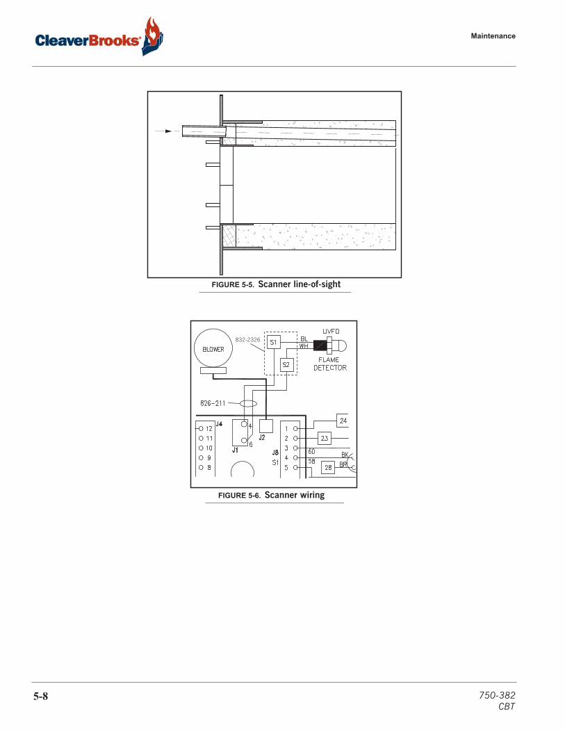
Maintenance
FIGURE 5-5. Scanner line-of-sight
832-2326
FIGURE 5-6. Scanner wiring
5-8 750-382CBT
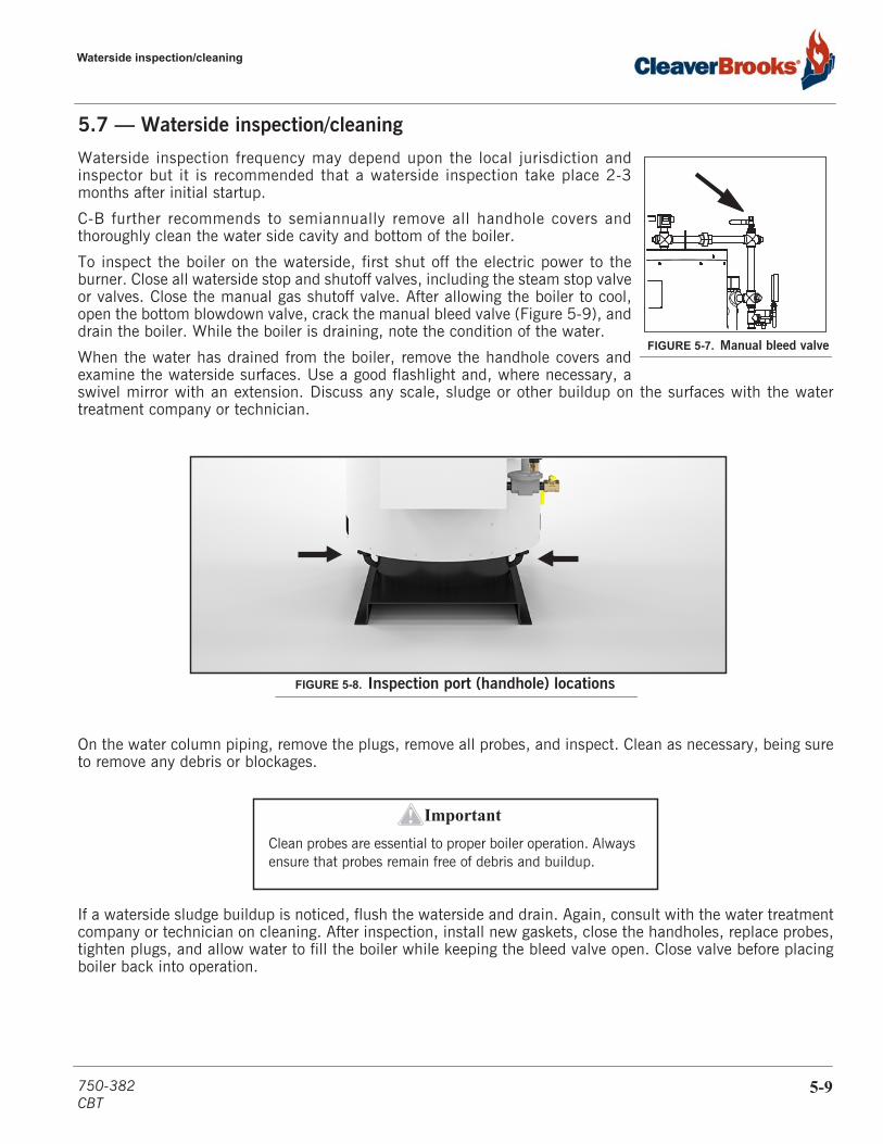
Waterside inspection/cleaning
5.7 — Waterside inspection/cleaning
Waterside inspection frequency may depend upon the local jurisdiction andinspector but it is recommended that a waterside inspection take place 2-3months after initial startup.
C-B further recommends to semiannually remove all handhole covers andthoroughly clean the water side cavity and bottom of the boiler.
To inspect the boiler on the waterside, first shut off the electric power to theburner. Close all waterside stop and shutoff valves, including the steam stop valveor valves. Close the manual gas shutoff valve. After allowing the boiler to cool,open the bottom blowdown valve, crack the manual bleed valve (Figure 5-9), anddrain the boiler. While the boiler is draining, note the condition of the water.
When the water has drained from the boiler, remove the handhole covers andexamine the waterside surfaces. Use a good flashlight and, where necessary, aswivel mirror with an extension. Discuss any scale, sludge or other buildup on the surfaces with the watertreatment company or technician.
On the water column piping, remove the plugs, remove all probes, and inspect. Clean as necessary, being sureto remove any debris or blockages.
If a waterside sludge buildup is noticed, flush the waterside and drain. Again, consult with the water treatmentcompany or technician on cleaning. After inspection, install new gaskets, close the handholes, replace probes,tighten plugs, and allow water to fill the boiler while keeping the bleed valve open. Close valve before placingboiler back into operation.
FIGURE 5-7. Manual bleed valve
FIGURE 5-8. Inspection port (handhole) locations
Important!Clean probes are essential to proper boiler operation. Always ensure that probes remain free of debris and buildup.
750-382CBT
5-9
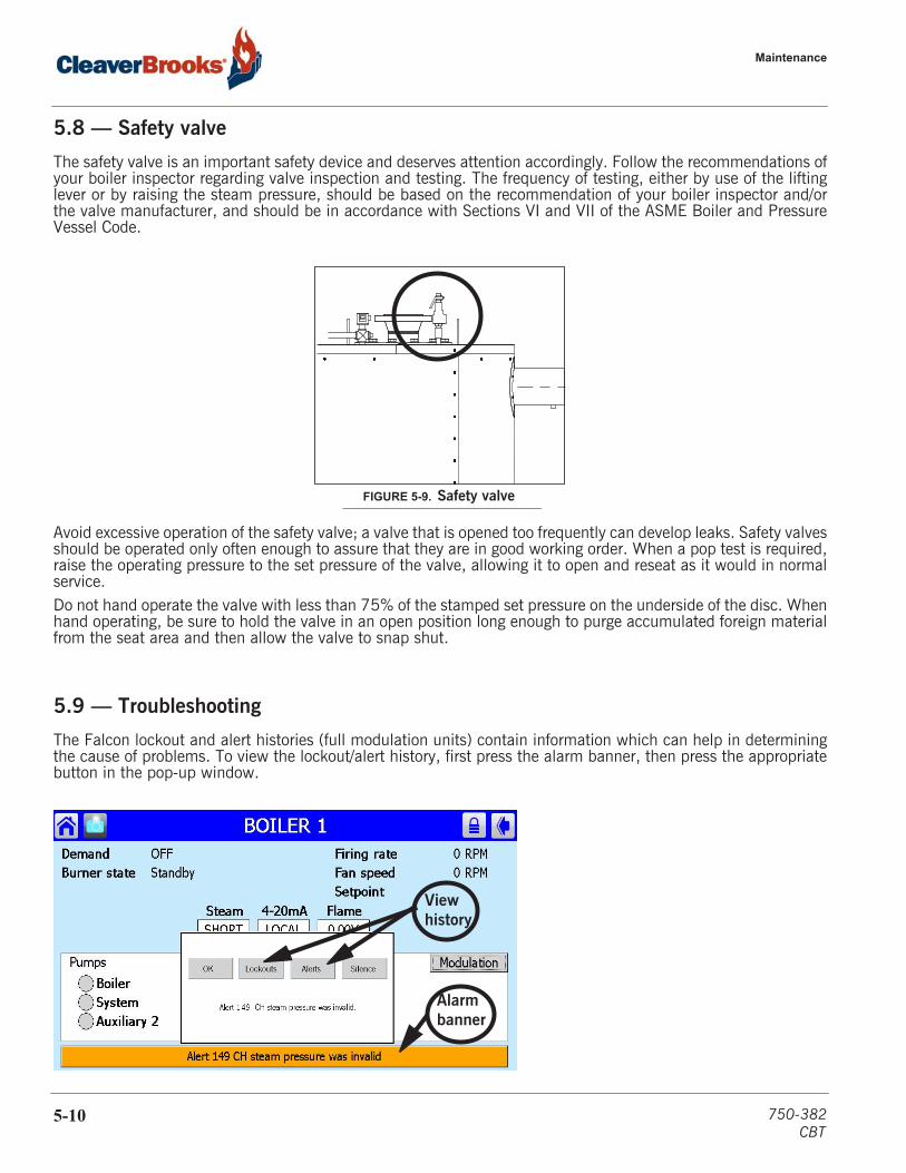
Maintenance
5.8 — Safety valve
The safety valve is an important safety device and deserves attention accordingly. Follow the recommendations ofyour boiler inspector regarding valve inspection and testing. The frequency of testing, either by use of the liftinglever or by raising the steam pressure, should be based on the recommendation of your boiler inspector and/orthe valve manufacturer, and should be in accordance with Sections VI and VII of the ASME Boiler and PressureVessel Code.
Avoid excessive operation of the safety valve; a valve that is opened too frequently can develop leaks. Safety valvesshould be operated only often enough to assure that they are in good working order. When a pop test is required,raise the operating pressure to the set pressure of the valve, allowing it to open and reseat as it would in normalservice.Do not hand operate the valve with less than 75% of the stamped set pressure on the underside of the disc. Whenhand operating, be sure to hold the valve in an open position long enough to purge accumulated foreign materialfrom the seat area and then allow the valve to snap shut.
5.9 — Troubleshooting
The Falcon lockout and alert histories (full modulation units) contain information which can help in determiningthe cause of problems. To view the lockout/alert history, first press the alarm banner, then press the appropriatebutton in the pop-up window.
FIGURE 5-9. Safety valve
Alarmbanner
Viewhistory
5-10 750-382CBT

Troubleshooting
The alert (or lockout) list will appear, showing date and time for each item. Pressing an individual item in the listwill display additional information. Diagnostic information available for lockouts includes annunciator status,states of system inputs, and steam pressure at time of lockout.
The Falcon display touch-screen interface is a valuable tool to help identify and resolve conditions that prevent normal and safe operation of the boiler. The focus of this section is to help the boiler operator utilize the Falcon display interface to evaluate and correct conditions that can cause nuisance shutdowns and contribute to unsafe operation of the boiler.
There are 3 levels of “alarm” conditions utilized by the Falcon controller: Lockout, Hold, and Alert. Lockouts and Holds indicate interruptions in boiler operation, whether occurring as part of the normal operating sequence or due to an abnormal condition. Lockouts always require a manual reset to resume operation, while Holds will automatically resume when the hold condition is removed or satisfied. Alerts indicate conditions or events which, while not preventing normal boiler operation, may be of interest in evaluating boiler operating conditions. Alerts require no operator acknowledgment and are for informational purposes only.
A Lockout will result in boiler shut down and always requires a manual reset of the Falcon controller. In certain cases, a lockout may also require a manual reset of a safety control interlock device connected to the Falcon. These include the auxiliary low water cut-off, high limit control, and gas pressure limit controls. Typically, a safety interlock can only be reset when the condition that caused the lockout has been corrected (i.e. water level returns to normal allowing the auxiliary low water cut-off to be reset).
Lockouts, Holds, and Alerts will often provide clues to the cause of the interruption or abnormal condition that generated the message. However, sometimes these messages can be misleading and may not point directly to the actual cause of the condition. A careful reading of this chapter, the rest of the manual, and the boiler specific wiring diagram will help in resolving boiler interruptions and abnormal conditions.
The key to diagnosing recurring nuisance interruptions is to identify the underlying cause of the condition that led to the interruption. Once the underlying cause is identified a permanent solution can implemented. Too often, safety controls are reset without proper analysis of the operating condition that caused the boiler operation inter-ruption. If not adequately addressed, the interruptions tend to be repeated with increasing frequency resulting in down time and increased maintenance. Merely resetting a safety control device does not resolve the cause of the condition that led to the lockout!
The following chart takes a methodical approach to diagnosing abnormal boiler operating conditions. This approach begins with the “Problem” as identified by the operator. The 2nd column indicates displayed messages (“Display Message”) by the Falcon display interface that will generally provide clues to the cause of the problem. The 3rd column lists “Possible Causes” and/or related “Symptoms” associated with the “Problem” and “Dis-played Message”. The 4th column recommends a “Diagnostic Check” that should be investigated for a potential cause or system. The last column provides recommendation for “Corrective Measures” to resolve the problem and return to normal operation.
This chart includes the most common conditions and resolutions for successful ClearFire boiler operation. It does not include all possible lockouts and alerts. The Falcon controller appendix has a comprehensive list of lockouts, holds, and alerts. The boiler operator can use this format and method to diagnose other conditions that may not be included here.
750-382CBT
5-11
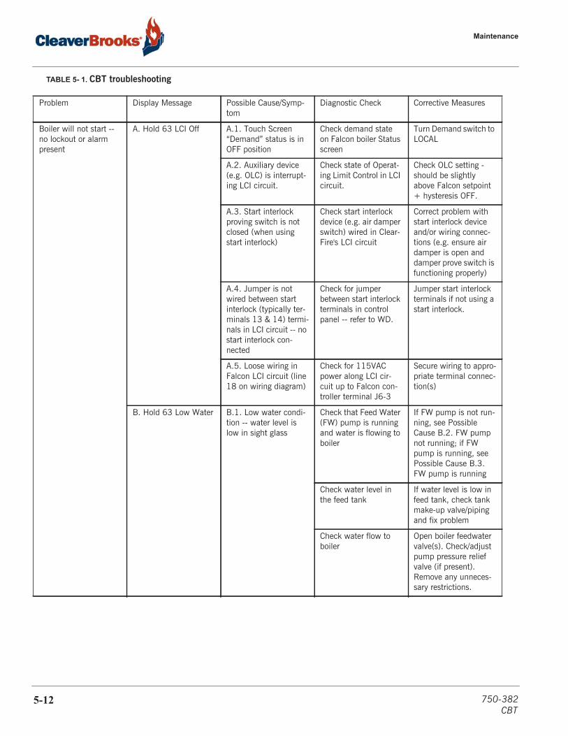
Maintenance
TABLE 5- 1. CBT troubleshooting
Problem Display Message Possible Cause/Symp-tom
Diagnostic Check Corrective Measures
Boiler will not start -- no lockout or alarm present
A. Hold 63 LCI Off A.1. Touch Screen “Demand” status is in OFF position
Check demand state on Falcon boiler Status screen
Turn Demand switch to LOCAL
A.2. Auxiliary device (e.g. OLC) is interrupt-ing LCI circuit.
Check state of Operat-ing Limit Control in LCI circuit.
Check OLC setting - should be slightly above Falcon setpoint + hysteresis OFF.
A.3. Start interlock proving switch is not closed (when using start interlock)
Check start interlock device (e.g. air damper switch) wired in Clear-Fire's LCI circuit
Correct problem with start interlock device and/or wiring connec-tions (e.g. ensure air damper is open and damper prove switch is functioning properly)
A.4. Jumper is not wired between start interlock (typically ter-minals 13 & 14) termi-nals in LCI circuit -- no start interlock con-nected
Check for jumper between start interlock terminals in control panel -- refer to WD.
Jumper start interlock terminals if not using a start interlock.
A.5. Loose wiring in Falcon LCI circuit (line 18 on wiring diagram)
Check for 115VAC power along LCI cir-cuit up to Falcon con-troller terminal J6-3
Secure wiring to appro-priate terminal connec-tion(s)
B. Hold 63 Low Water B.1. Low water condi-tion -- water level is low in sight glass
Check that Feed Water (FW) pump is running and water is flowing to boiler
If FW pump is not run-ning, see Possible Cause B.2. FW pump not running; if FW pump is running, see Possible Cause B.3. FW pump is running
Check water level in the feed tank
If water level is low in feed tank, check tank make-up valve/piping and fix problem
Check water flow to boiler
Open boiler feedwater valve(s). Check/adjust pump pressure relief valve (if present). Remove any unneces-sary restrictions.
5-12 750-382CBT
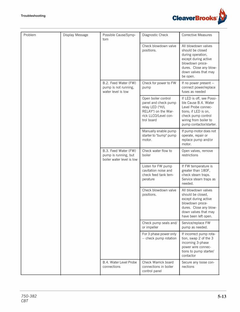
Troubleshooting
Check blowdown valve positions.
All blowdown valves should be closed during operation, except during active blowdown proce-dures. Close any blow-down valves that may be open.
B.2. Feed Water (FW) pump is not running, water level is low
Check for power to FW pump
If no power present -- connect power/replace fuses as needed
Open boiler control panel and check pump relay LED ("H/L RELAY") on the War-rick LLCO/Level con-trol board
If LED is off, see Possi-ble Cause B.4. Water Level Probe connec-tions; if LED is on, check pump control wiring from boiler to pump contactor/starter.
Manually enable pump starter to "bump" pump motor.
If pump motor does not operate, repair or replace pump and/or motor.
B.3. Feed Water (FW) pump is running, but boiler water level is low
Check water flow to boiler
Open valves, remove restrictions
Listen for FW pump cavitation noise and check feed tank tem-perature
If FW temperature is greater than 180F, check steam traps. Service steam traps as needed.
Check blowdown valve positions.
All blowdown valves should be closed, except during active blowdown proce-dures. Close any blow-down valves that may have been left open.
Check pump seals and/or impeller
Service/replace FW pump as needed.
For 3 phase power only -- check pump rotation
If incorrect pump rota-tion, swap 2 of the 3 incoming 3-phase power wire connec-tions to pump starter/contactor
B.4. Water Level Probe connections
Check Warrick board connections in boiler control panel
Secure any loose con-nections
Problem Display Message Possible Cause/Symp-tom
Diagnostic Check Corrective Measures
750-382CBT
5-13

Maintenance
Inspect high-temp wire-to-probe connec-tions in boiler water column connection box (Warrick)
Tighten jam nuts on any loose probe con-nections.
If slight corrosion pres-ent, remove terminal connection, clean crimp-on ring termi-nal, re-crimp, and replace with copper flat washer between ring terminal and jam nut, tightening jam nut to secure ring terminal. Apply dielectric grease to terminal connec-tions.
If severe corrosion present, cut-off crimp-on ring terminal, strip wire end, crimp-on new high temperature, SS ring terminal, reat-tach with copper flat washer between ring terminal and jam nut. Apply dielectric grease to terminal connec-tions.
If all connections secure and clean, see Possible Cause B.5. Dirty water level probes
B.5. Dirty water level probes
Check Warrick board "dirty probe" LED. If off, remove associated probe wire from War-rick DF board and check continuity between probe and panel ground.
If no continuity, remove probe. Visually inspect and clean or replace. Secure all wiring con-nections and coat wire terminal ring connec-tion in probe head with dielectric grease.
Check feed water treat-ment/softening. Per-form water softening and chemical treat-ment as necessary.
Problem Display Message Possible Cause/Symp-tom
Diagnostic Check Corrective Measures
5-14 750-382CBT
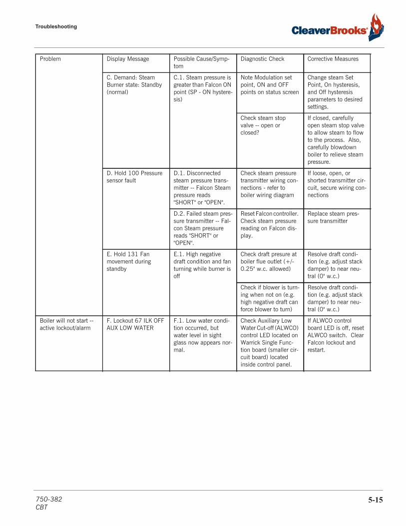
Troubleshooting
C. Demand: Steam Burner state: Standby (normal)
C.1. Steam pressure is greater than Falcon ON point (SP - ON hystere-sis)
Note Modulation set point, ON and OFF points on status screen
Change steam Set Point, On hysteresis, and Off hysteresis parameters to desired settings.
Check steam stop valve -- open or closed?
If closed, carefully open steam stop valve to allow steam to flow to the process. Also, carefully blowdown boiler to relieve steam pressure.
D. Hold 100 Pressure sensor fault
D.1. Disconnected steam pressure trans-mitter -- Falcon Steam pressure reads "SHORT" or "OPEN".
Check steam pressure transmitter wiring con-nections - refer to boiler wiring diagram
If loose, open, or shorted transmitter cir-cuit, secure wiring con-nections
D.2. Failed steam pres-sure transmitter -- Fal-con Steam pressure reads "SHORT" or "OPEN".
Reset Falcon controller. Check steam pressure reading on Falcon dis-play.
Replace steam pres-sure transmitter
E. Hold 131 Fan movement during standby
E.1. High negative draft condition and fan turning while burner is off
Check draft presure at boiler flue outlet (+/- 0.25" w.c. allowed)
Resolve draft condi-tion (e.g. adjust stack damper) to near neu-tral (0" w.c.)
Check if blower is turn-ing when not on (e.g. high negative draft can force blower to turn)
Resolve draft condi-tion (e.g. adjust stack damper) to near neu-tral (0" w.c.)
Boiler will not start -- active lockout/alarm
F. Lockout 67 ILK OFF AUX LOW WATER
F.1. Low water condi-tion occurred, but water level in sight glass now appears nor-mal.
Check Auxiliary Low Water Cut-off (ALWCO) control LED located on Warrick Single Func-tion board (smaller cir-cuit board) located inside control panel.
If ALWCO control board LED is off, reset ALWCO switch. Clear Falcon lockout and restart.
Problem Display Message Possible Cause/Symp-tom
Diagnostic Check Corrective Measures
750-382CBT
5-15
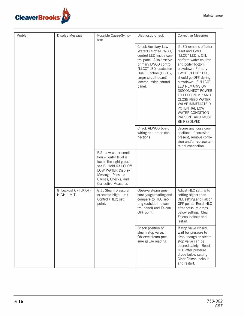
Maintenance
Check Auxiliary Low Water Cut-off (ALWCO) control LED inside con-trol panel. Also observe primary LWCO control “LLCO” LED located on Dual Function (DF-16, larger circuit board) located inside control panel.
If LED remains off after reset and LWCO “LLCO” LED is ON, perform water column and boiler bottom blowdown. Primary LWCO (“LLCO” LED) should go OFF during blowdown. IF “LLCO” LED REMAINS ON, DISCONNECT POWER TO FEED PUMP AND CLOSE FEED WATER VALVE IMMEDIATELY. POTENTIAL LOW WATER CONDITION PRESENT AND MUST BE RESOLVED!
Check ALWCO board wiring and probe con-nections
Secure any loose con-nections. If corrosion present, remove corro-sion and/or replace ter-minal connection.
F.2. Low water condi-tion -- water level is low in the sight glass -- see B. Hold 63 LCI Off LOW WATER Display Message, Possible Causes, Checks, and Corrective Measures
G. Lockout 67 ILK OFF HIGH LIMIT
G.1. Steam pressure exceeded High Limit Control (HLC) set point.
Observe steam pres-sure gauge reading and compare to HLC set-ting (outside the con-trol panel) and Falcon OFF point.
Adjust HLC setting to setting higher than OLC setting and Falcon OFF point. Reset HLC after pressure drops below setting. Clear Falcon lockout and restart.
Check position of steam stop valve. Observe steam pres-sure gauge reading.
If stop valve closed, wait for pressure to drop enough so steam stop valve can be opened safely. Reset HLC after pressure drops below setting. Clear Falcon lockout and restart.
Problem Display Message Possible Cause/Symp-tom
Diagnostic Check Corrective Measures
5-16 750-382CBT
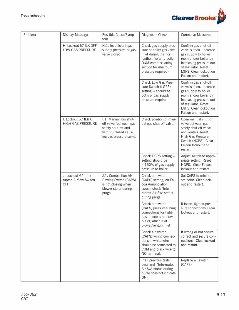
Troubleshooting
H. Lockout 67 ILK OFF LOW GAS PRESSURE
H.1. Insufficient gas supply pressure or gas valve closed
Check gas supply pres-sure at boiler gas valve inlet during trial for ignition (refer to boiler O&M commissioning section for minimum pressure required).
Confirm gas shut-off valve is open. Increase gas supply to boiler room and/or boiler by increasing pressure out of regulator. Reset LGPS. Clear lockout on Falcon and restart.
Check Low Gas Pres-sure Switch (LGPS) setting -- should be 50% of gas supply pressure required.
Confirm gas shut-off valve is open. Increase gas supply to boiler room and/or boiler by increasing pressure out of regulator. Reset LGPS. Clear lockout on Falcon and restart.
I. Lockout 67 ILK OFF HIGH GAS PRESSURE
I.1. Manual gas shut-off valve (between gas safety shut-off and venturi) closed caus-ing gas pressure spike.
Check position of man-ual gas shut-off valve.
Open manual shut-off valve between gas safety shut-off valve and venturi. Reset High Gas Pressure Switch (HGPS). Clear Falcon lockout and restart.
Check HGPS setting -- setting should be ~150% of gas supply pressure to boiler.
Adjust switch to appro-priate setting. Reset HGPS. Clear Falcon lockout and restart.
J. Lockout 65 Inter-rupted Airflow Switch OFF
J.1. Combustion Air Proving Switch (CAPS) is not closing when blower starts during purge
Check air switch (CAPS) setting; on Fal-con Annunciation screen check "Inter-rupted Air Sw" status during purge
Set CAPS to minimum set point. Clear lock-out and restart.
Check air switch (CAPS) pressure tubing connections for tight-ness -- one is at blower outlet, other is at blower/venturi inlet
If loose, tighten pres-sure connections. Clear lockout and restart.
Check air switch (CAPS) wiring connec-tions -- white wire should be connected to COM and black wire to NO terminal.
If wrong or not secure, correct and secure con-nections. Clear lockout and restart.
If all previous tests pass and "Interrupted Air Sw" status during purge does not indicate ON:
Replace air switch (CAPS)
Problem Display Message Possible Cause/Symp-tom
Diagnostic Check Corrective Measures
750-382CBT
5-17
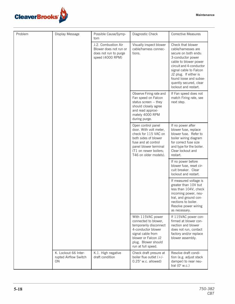
Maintenance
J.2. Combustion Air Blower does not run or does not run to purge speed (4000 RPM)
Visually inspect blower cable/harness connec-tions.
Check that blower cable/harnesses are secure on both ends: 3-conductor power cable to blower power circuit and 4-conductor signal cable to Falcon J2 plug. If either is found loose and subse-quently secured, clear lockout and restart.
Observe Firing rate and Fan speed on Falcon status screen -- they should closely agree and read approxi-mately 4000 RPM during purge.
If Fan speed does not match Firing rate, see next step.
Open control panel door. With volt meter, check for 115 VAC on both sides of blower fuse and at control panel blower terminal (T1 on newer boilers; T46 on older models).
If no power after blower fuse, replace blower fuse. Refer to boiler wiring diagram for correct fuse size and type for the boiler. Clear lockout and restart.
If no power before blower fuse, reset cir-cuit breaker. Clear lockout and restart.
If measured voltage is greater than 10V but less than 104V, check incoming power, neu-tral, and ground con-nections to boiler. Resolve power wiring as necessary.
With 115VAC power connected to blower, temporarily disconnect 4-conductor blower signal cable from blower or Falcon J2 plug. Blower should run at full speed.
If 115VAC power con-firmed at blower con-nection and blower does not run, contact factory and/or replace blower assembly.
K. Lockout 66 Inter-rupted Airflow Switch ON
K.1. High negative draft condition
Check draft presure at boiler flue outlet (+/- 0.25" w.c. allowed)
Resolve draft condi-tion (e.g. adjust stack damper) to near neu-tral (0" w.c.)
Problem Display Message Possible Cause/Symp-tom
Diagnostic Check Corrective Measures
5-18 750-382CBT

Troubleshooting
Check if blower is turn-ing when not on.
Resolve draft condi-tion (e.g. adjust stack damper) to near neu-tral (0" w.c.)
K.2. Blower running when boiler is off
Check Firing rate and Fan speed on Falcon status screen
If Firing rate indicates 0 or low RPM and Fan speed is at a high RPM, inspect/secure blower signal cable connections at both ends. A disconnected blower signal cable will result in the blower running at full speed.
At Operation screen, check Modulation Fir-ing rate setting
If set to "Manual in Run & Standby", set to "Automatic" or "Man-ual in Run"
K.3. Combustion Air Proving switch (CAPS) failure
Check switch connec-tions and proper func-tion of air switch.
Correct/secure connec-tions. Clear lockout and restart. If CAPS not functioning, replace air switch.
Light-off problems L. Lockout 109 Igni-tion Failure
L.1. Gas supply - is pressure too low at boiler gas valve inlet during trial for ignition
Check for flame signal on boiler status screen (DC Volts)
Increase gas supply pressure to boiler room
(refer to manual's com-missioning section for minimum gas supply pressure requirement and recommended gas line sizing)
Increase gas supply pipe size
Adjust setting of boiler gas regulator
Clear Lockout and try again
L.2. Manual gas valve located between gas valve and venturi closed
Check position of man-ual shut-off valves
Open Manual Gas Valve
L.3. Gas safety shut-off valve not opening
Check gas valve indica-tor LED's during trial for ignition
If LED(s) not energiz-ing, secure gas valve wiring connections. Refer to boiler wiring diagram. Ensure DIN connector is secured to gas valve.
Problem Display Message Possible Cause/Symp-tom
Diagnostic Check Corrective Measures
750-382CBT
5-19
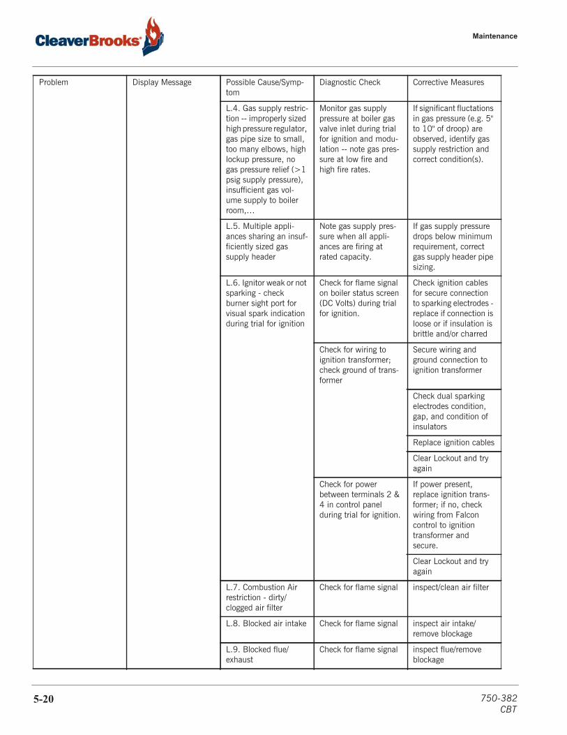
Maintenance
L.4. Gas supply restric-tion -- improperly sized high pressure regulator, gas pipe size to small, too many elbows, high lockup pressure, no gas pressure relief (>1 psig supply pressure), insufficient gas vol-ume supply to boiler room,…
Monitor gas supply pressure at boiler gas valve inlet during trial for ignition and modu-lation -- note gas pres-sure at low fire and high fire rates.
If significant fluctations in gas pressure (e.g. 5" to 10" of droop) are observed, identify gas supply restriction and correct condition(s).
L.5. Multiple appli-ances sharing an insuf-ficiently sized gas supply header
Note gas supply pres-sure when all appli-ances are firing at rated capacity.
If gas supply pressure drops below minimum requirement, correct gas supply header pipe sizing.
L.6. Ignitor weak or not sparking - check burner sight port for visual spark indication during trial for ignition
Check for flame signal on boiler status screen (DC Volts) during trial for ignition.
Check ignition cables for secure connection to sparking electrodes - replace if connection is loose or if insulation is brittle and/or charred
Check for wiring to ignition transformer; check ground of trans-former
Secure wiring and ground connection to ignition transformer
Check dual sparking electrodes condition, gap, and condition of insulators
Replace ignition cables
Clear Lockout and try again
Check for power between terminals 2 & 4 in control panel during trial for ignition.
If power present, replace ignition trans-former; if no, check wiring from Falcon control to ignition transformer and secure.
Clear Lockout and try again
L.7. Combustion Air restriction - dirty/clogged air filter
Check for flame signal inspect/clean air filter
L.8. Blocked air intake Check for flame signal inspect air intake/remove blockage
L.9. Blocked flue/exhaust
Check for flame signal inspect flue/remove blockage
Problem Display Message Possible Cause/Symp-tom
Diagnostic Check Corrective Measures
5-20 750-382CBT

Troubleshooting
L.10. Burner canister clogged
Check for flame signal inspect burner/clean surface. Replace burner canister if clogged or damaged.
Clear Lockout and try again
L.11. No or poor flame signal (less than 1 VDC) -- UV flame sens-ing
Check for flame sig-nal; Visually check for ignition in burner sight port
If flame observed, inspect UV scanner; remove and clean as necessary and rein-stall.
Remove UV scanner for inspection.
Inspect scanner mounting tube for clear line-of-sight to burner canister - remove any blockages that would inhibit scanner view-ing.
Shut-off gas supply; remove UV scanner from burner mount, with match or lighter, place flame in front of UV scanner -- observe displayed flame signal on boiler status screen
If no flame signal, replace UV scanner with new one. If yes, remount UV scanner at burner. Open gas shut-off valve.
Clear Lockout and try again
If condition persists, contact factory
L.12. No or poor flame signal (less than 1 VDC) -- flame rod sens-ing
Check for flame sig-nal; Visually check for ignition in burner sight port
If flame is observed, remove flame rod, inspect, clean and rein-stall. Replace as nec-essary based on usage and environmental conditions.
M. Lockout 107 Flame lost early run
M.1. Refer to L. Lock-out 109 Possible Causes and Corrective Measures
M.2. Poor combustion tuning
With combustion ana-lyzer, compare O2 lev-els at HF and LF with manual recommeda-tions.
Retune combustion settings as necessary.
Problem Display Message Possible Cause/Symp-tom
Diagnostic Check Corrective Measures
750-382CBT
5-21

Maintenance
M.3. Flame Rod (Ion-ization Electrode) grounding itself
Check flame signal and inspect flame rod posi-tion.
Increase the gap between the flame rod tip to the burner canis-ter surface. Replace flame rod if damaged.
N. Lockout 122 Ligh-toff rate proving failed
N.1. Blower speed sig-nal cable is too close to ignition cables
Observe RPM on dis-play during trial for ignition
Route blower signal cable at least 12" away from ignition cables.
Clear Lockout and try again
N.2. Blower speed control not functioning properly
On display screen, compare Fan speed to Firing rate command.
If blower/fan speed does not respond to Firing rate command, perform the following Diagnostic Checks.
If Fan speed is slow to respond to Firing rate command, adjust the Fan gain up and down parameters in Fan Con-figuration group for better response.
Check that blower sig-nal cable is securely connected at both ends -- Falcon control J2 socket and blower speed control signal socket.
Secure blower signal cable connections.
Check blower AC power fuse and con-nections.
If AC power not pres-ent replace fuse.
If AC power low, check blower wiring circuit for proper connec-tions. Check ground to boiler control panel.
With boiler demand is off, temporarily discon-nect blower signal cable. With AC power connected, blower should go to max speed.
If blower does not respond, recheck blower AC power cir-cuit. If AC power is OK, replace blower.
Clear Lockout and try again
If condition persists, contact factory
Problem Display Message Possible Cause/Symp-tom
Diagnostic Check Corrective Measures
5-22 750-382CBT

Troubleshooting
O. Lockout 173 Pilot relay feedback error
O.1. Loose wire or neu-tral in fuel valve circuit
Check fuel valve wir-ing from control panel to gas valve connection DIN connector. With power disconnected, perform continuity check of each wire from control panel ter-minal to fuel valve DIN connector. Refer to boiler wiring diagram.
Correct/secure any loose wire connections in fuel valve circuit. Ensure DIN connector is secured to gas valve.
P. Lockout 174 Safety relay feedback error
P.1. High ambient tem-perature inside control panel.
Measure temperature in boiler room and inside control panel.
If room is greater than 120F, ventilate room with cooler make-up air. If control panel is greater than 140F, ventilate control panel.
P.2. Falcon "pump" relay output assigned task, but not used
Refer to boiler wiring diagram for Falcon "pump" relay connec-tions. Access Falcon Pump Configuration menu.
Set all pump control block assignments that are not being used to “None”.
P.3. External electrical noise (e.g. ignition sparking) near Falcon control circuit
Check that all electrical noise sources (e.g. ignition cables) are kept away from the Falcon controller and connected control cir-cuit wiring.
Separate and secure all control wiring from electrical noise genera-tors such as ignition transformer and cables.
P.4. Faulty safety inter-lock control (e.g. ALWCO, HLC, HGPS, LGPS);
Check function of each safety interlock switch in ILK circuit.
Secure wiring connec-tions or replace faulty safety interlock control device.
If condition persists, contact factory
Flame Failure Q. Lockout 108 Flame failure in Run
Q.1. Refer to Lockout 109 & 107 Possible Causes and Corrective Measures -- except for Ignitor not sparking
Check Lockout History for boiler state/status and cycle run time when lockout occurred.
If feasible, identify potential adverse oper-ating conditions at time of lockout (e.g. low fire or high fire?) and remedy.
Q.2. Poor combustion tuning
With combustion ana-lyzer, compare O2 lev-els at HF and LF with manual recommeda-tions.
Retune combustion settings as necessary.
Problem Display Message Possible Cause/Symp-tom
Diagnostic Check Corrective Measures
750-382CBT
5-23
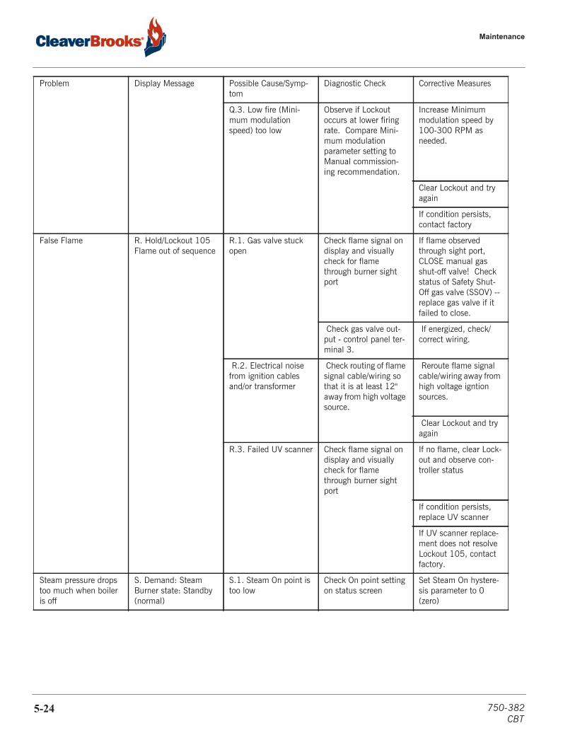
Maintenance
Q.3. Low fire (Mini-mum modulation speed) too low
Observe if Lockout occurs at lower firing rate. Compare Mini-mum modulation parameter setting to Manual commission-ing recommendation.
Increase Minimum modulation speed by 100-300 RPM as needed.
Clear Lockout and try again
If condition persists, contact factory
False Flame R. Hold/Lockout 105 Flame out of sequence
R.1. Gas valve stuck open
Check flame signal on display and visually check for flame through burner sight port
If flame observed through sight port, CLOSE manual gas shut-off valve! Check status of Safety Shut-Off gas valve (SSOV) -- replace gas valve if it failed to close.
Check gas valve out-put - control panel ter-minal 3.
If energized, check/correct wiring.
R.2. Electrical noise from ignition cables and/or transformer
Check routing of flame signal cable/wiring so that it is at least 12" away from high voltage source.
Reroute flame signal cable/wiring away from high voltage igntion sources.
Clear Lockout and try again
R.3. Failed UV scanner Check flame signal on display and visually check for flame through burner sight port
If no flame, clear Lock-out and observe con-troller status
If condition persists, replace UV scanner
If UV scanner replace-ment does not resolve Lockout 105, contact factory.
Steam pressure drops too much when boiler is off
S. Demand: Steam Burner state: Standby (normal)
S.1. Steam On point is too low
Check On point setting on status screen
Set Steam On hystere-sis parameter to 0 (zero)
Problem Display Message Possible Cause/Symp-tom
Diagnostic Check Corrective Measures
5-24 750-382CBT

Troubleshooting
S.2. Anti-short cycle time is too long
Check anti-short cycle time
Reduce ant-short cycle time parameter; set to 0 to disable this func-tion. Anti-short cycle is located in the "Steam Configuration" parame-ter group.
Boiler cycles on and off too frequently
T. Demand: Steam Burner state: Standby (normal)
T.1. Steam Off hystere-sis setting is too low
Check Steam Off point on boiler status screen
Increase the Steam Off point hysteresis param-eter setting to allow boiler to modulate lon-ger before shutting off.
T.2. PID gains are too aggressive, or too high
Check P (proportional) and I (integral) gain settings.
Reduce the gain values for both P and I gain. Observer control of boiler to meet steam pressure set point.
TABLE 5- 2. Common abbreviations
WD Wiring Diagram
ILK Safety InterLock circuit (always require a manual reset)
LCI Limit Control Input circuit (resets automatically)
SP Set Point (steam pressure)
PID Proportional-Integral-Derivative (control method)
SSOV Safety Shut-Off Valve
FW Feed Water
LWCO Low Water Cut-Off
ALWCO Auxiliary Low Water Cut-Off
CAPS Combustion Air Proving Switch
LGPS Low Gas Pressure Switch
HGPS High Gas Pressure Switch
HLC High Limit Control (steam pressure)
OLC Operating Limit Control (steam pressure)
LED Light Emitting Diode (common on solid state controls, such as LWCO)
AC or VAC Alternating Current (electrical power) or Voltage AC
DC or VDC Direct Current (electrical power) or Voltage DC
RPM Revolutions Per Minute (combustion air fan speed or firing rate)
DIN electrical connector type defined by German standards association
UV Ultra-Violet (flame scanner type)
Problem Display Message Possible Cause/Symp-tom
Diagnostic Check Corrective Measures
750-382CBT
5-25
Maintenance
5.10 — Display diagnostics
The CB Falcon display/interface provides diagnostic features under the Setup menu. To access display diagnostics,beginning on the Home screen, press <Setup>, then <Display Diagnostics>If the touch screen is not working properly, it may require re-calibration. Go to Display Diagnostics as above andpress <Calibrate Screen>. Follow the on-screen instructions.Date and timeThe Setup menu also allows access to system Date and Time settings. Press <Setup>, <Display Setup>, <SetDate/Time>.
5.11 — Lay-up
If the boiler will be out of use for an extended period, precautions must be taken to protect fireside and watersidesurfaces from deterioration due to corrosion.At the start of lay-up, thoroughly clean the fireside by removing any soot or other products of combustion fromthe fireside surfaces. After brushing all surfaces clean, sweep away or vacuum any residue. The fireside may beflushed with water; however, all surfaces should be completely dried before lay-up.
Dry lay-upDry lay-up is generally used when the boiler will be out of service for a lengthy time period, or where the boilermight be subject to freezing temperatures. The boiler must be thoroughly dried before dry storage, as any moisturecould cause corrosion. Both fireside and waterside surfaces must be cleaned of all scale, deposits, soot, etc. Adesiccant such as quick lime or silica gel should be placed in suitable containers inside the boiler vessel.
Wet lay-upWet storage is generally used when a boiler may be needed on short notice or in cases where dry storage is notpractical. Before wet storage the vessel should be drained, thoroughly cleaned, and refilled to overflowing withtreated water. If deaerated water is not available, the unit should be fired to boil the water for a short period oftime.Whichever method of lay-up is used, a periodic re-check of fireside and waterside conditions is recommendedduring lay-up.
5-26 750-382CBT
CHAPTER 6 Parts
Recommended spare parts list 6-2
Safety valves 6-2
Control panel 6-3
Burner assembly 6-5
Water Column 6-13
Gas train 6-14Direct vent kits 6-15
750-382CBT
6-1

Parts
6.1 — Recommended spare parts list
6.2 — Safety valves
PART NUMBERDESCRIPTION 9.5 HP 10-15 HP 20-25 HP 30 HP 40 HP 50 HPFalcon controller, steam 833-03578Falcon Display 833-05105Power Supply, 12VDC 832-02179Gasket, Adapter Plate To Blower 380-00552 380-01037 380-01038 380-01076Gasket, Burner Canister (2) 380-00551 380-01136 380-00902 380-01169Burner Canister 380-00021 380-01134 380-00900 380-01170 380-00904Ignition Cable (2) 826-00156Pressure Gauge, 0-300 PSI 850-00122Gasket, Electrode 380-01032Scanner Assembly, UV 817-01743Electrode, Ignition 380-01174 380-01172 380-00550Gasket, Venturi 800-00098Burner Sight Glass 851-06429Gasket, Handhole (3) 853-00934Valve Set, Gauge Glass 825-00132Gauge Glass, Pyrex, Tubular 851-00199Protector Set, Gauge Glass 912-00085Probes, LWCO, Pump On/Off, HWA 817-03728Probe, ALWCO 067-00873Fuse, Blower 832-01881Fuse, Control Circuit, 5A 832-01811Fuse, DC Power Supply, 1A 832-02045Fuse, 24VAC Secondary, 2A 832-02051Ignition Transformer 832-02451Safety Relief Valve see table next page
CBT SAFETY VALVES
9.5 HP 100 psig
10 HP 150 psig
15 HP 150 psig
20 HP 150 psig
25 HP 150 psig
30 HP 150 psig
40 HP 150 psig
50 HP 150 psig
940-03069 940-02976 940-02976 940-02976 940-02588 940-02588 940-02588 940-02741
10 HP 15 psig
15 HP 15 psig
20 HP 15 psig
25 HP 15 psig
30 HP 15 psig
40 HP 15 psig
50 HP 15 psig
940-04991 940-04991 940-04991 940-04992 940-04992 940-04993 940-04993
6-2 750-382CBT
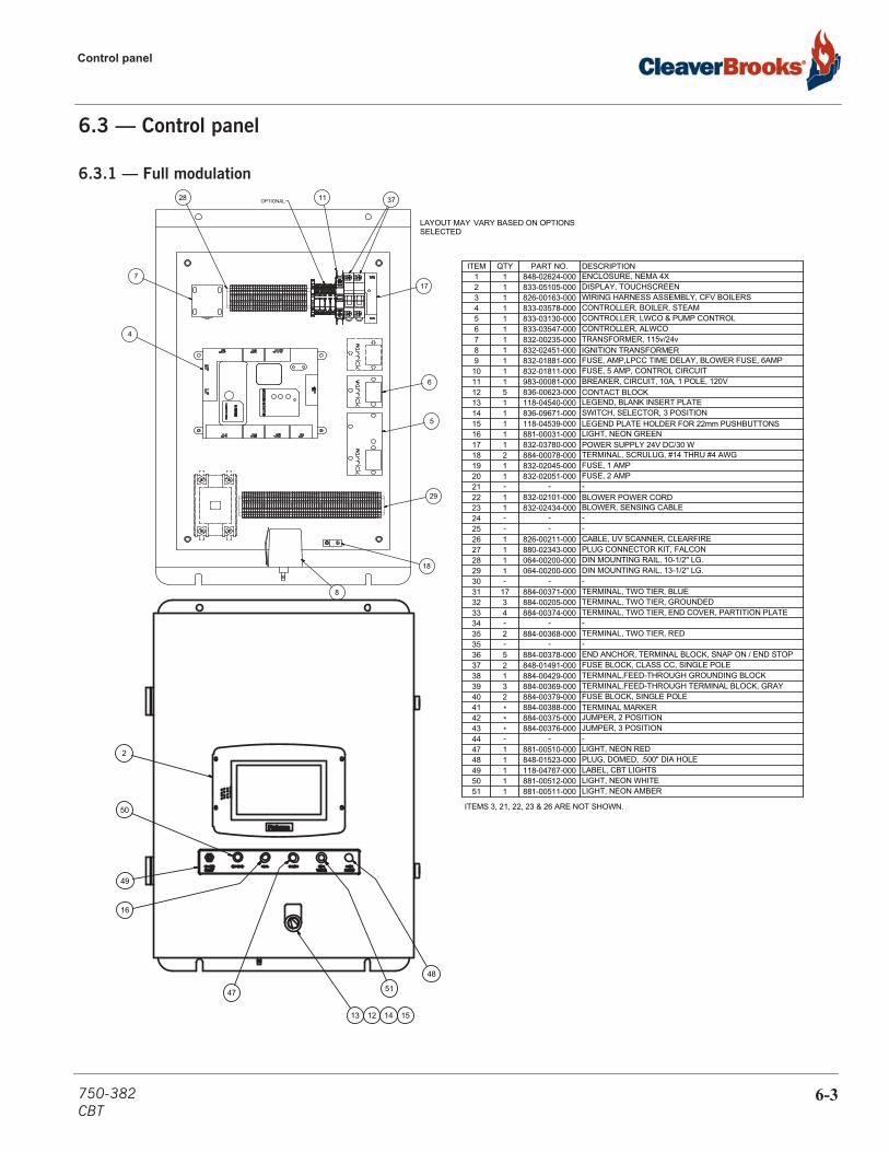
Control panel
6.3 — Control panel
6.3.1 — Full modulation
ITEMS 3, 21, 22, 23 & 26 ARE NOT SHOWN.
2
49
50
51
16
47
48
13 12 14 15
ITEM QTY PART NO. DESCRIPTION1 1 848-02624-000 ENCLOSURE, NEMA 4X2 1 833-05105-000 DISPLAY, TOUCHSCREEN3 1 826-00163-000 WIRING HARNESS ASSEMBLY, CFV BOILERS4 1 833-03578-000 CONTROLLER, BOILER, STEAM5 1 833-03130-000 CONTROLLER, LWCO & PUMP CONTROL6 1 833-03547-000 CONTROLLER, ALWCO7 1 832-00235-000 TRANSFORMER, 115v/24v8 1 832-02451-000 IGNITION TRANSFORMER9 1 832-01881-000 FUSE, AMP,LPCC TIME DELAY, BLOWER FUSE, 6AMP
10 1 832-01811-000 FUSE, 5 AMP, CONTROL CIRCUIT11 1 983-00081-000 BREAKER, CIRCUIT, 10A, 1 POLE, 120V12 5 836-00623-000 CONTACT BLOCK13 1 118-04540-000 LEGEND, BLANK INSERT PLATE14 1 836-09671-000 SWITCH, SELECTOR, 3 POSITION15 1 118-04539-000 LEGEND PLATE HOLDER FOR 22mm PUSHBUTTONS16 1 881-00031-000 LIGHT, NEON GREEN17 1 832-03780-000 POWER SUPPLY 24V DC/30 W18 2 884-00078-000 TERMINAL, SCRULUG, #14 THRU #4 AWG19 1 832-02045-000 FUSE, 1 AMP20 1 832-02051-000 FUSE, 2 AMP21 - - -22 1 832-02101-000 BLOWER POWER CORD23 1 832-02434-000 BLOWER, SENSING CABLE24 - - -25 - - -26 1 826-00211-000 CABLE, UV SCANNER, CLEARFIRE27 1 880-02343-000 PLUG CONNECTOR KIT, FALCON28 1 064-00200-000 DIN MOUNTING RAIL, 10-1/2" LG.29 1 064-00200-000 DIN MOUNTING RAIL, 13-1/2" LG.30 - - -31 17 884-00371-000 TERMINAL, TWO TIER, BLUE32 3 884-00205-000 TERMINAL, TWO TIER, GROUNDED33 4 884-00374-000 TERMINAL, TWO TIER, END COVER, PARTITION PLATE34 - - -35 2 884-00368-000 TERMINAL, TWO TIER, RED35 - - -36 5 884-00378-000 END ANCHOR, TERMINAL BLOCK, SNAP ON / END STOP37 2 848-01491-000 FUSE BLOCK, CLASS CC, SINGLE POLE38 1 884-00429-000 TERMINAL,FEED-THROUGH GROUNDING BLOCK39 3 884-00369-000 TERMINAL,FEED-THROUGH TERMINAL BLOCK, GRAY40 2 884-00379-000 FUSE BLOCK, SINGLE POLE41 * 884-00388-000 TERMINAL MARKER42 * 884-00375-000 JUMPER, 2 POSITION43 * 884-00376-000 JUMPER, 3 POSITION44 - - -47 1 881-00510-000 LIGHT, NEON RED48 1 848-01523-000 PLUG, DOMED, .500" DIA HOLE49 1 118-04767-000 LABEL, CBT LIGHTS50 1 881-00512-000 LIGHT, NEON WHITE51 1 881-00511-000 LIGHT, NEON AMBER
5
6
29
17
3711OPTIONAL28
7
4
18
8
LAYOUT MAY VARY BASED ON OPTIONS SELECTED
750-382CBT
6-3

Parts
Continue to next page
6-4 750-382CBT
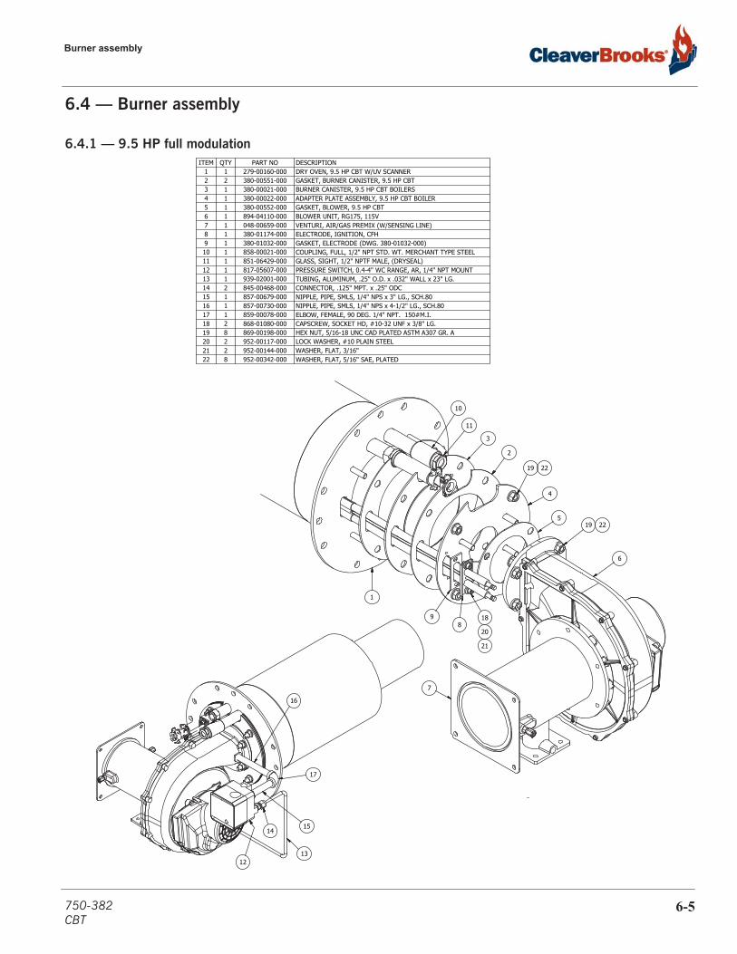
Burner assembly
6.4 — Burner assembly
6.4.1 — 9.5 HP full modulationDESCRIPTIONPART NOQTYITEMDRY OVEN, 9.5 HP CBT W/UV SCANNER279-00160-00011GASKET, BURNER CANISTER, 9.5 HP CBT380-00551-00022BURNER CANISTER, 9.5 HP CBT BOILERS380-00021-00013ADAPTER PLATE ASSEMBLY, 9.5 HP CBT BOILER380-00022-00014GASKET, BLOWER, 9.5 HP CBT380-00552-00015BLOWER UNIT, RG175, 115V894-04110-00016VENTURI, AIR/GAS PREMIX (W/SENSING LINE)048-00659-00017ELECTRODE, IGNITION, CFH380-01174-00018GASKET, ELECTRODE (DWG. 380-01032-000)380-01032-00019COUPLING, FULL, 1/2" NPT STD. WT. MERCHANT TYPE STEEL858-00021-000110GLASS, SIGHT, 1/2" NPTF MALE, (DRYSEAL)851-06429-000111PRESSURE SWITCH, 0.4-4" WC RANGE, AR, 1/4" NPT MOUNT817-05607-000112TUBING, ALUMINUM, .25" O.D. x .032" WALL x 23" LG.939-02001-000113CONNECTOR, .125" MPT. x .25" ODC845-00468-000214NIPPLE, PIPE, SMLS, 1/4" NPS x 3" LG., SCH.80857-00679-000115NIPPLE, PIPE, SMLS, 1/4" NPS x 4-1/2" LG., SCH.80857-00730-000116ELBOW, FEMALE, 90 DEG. 1/4" NPT. 150#M.I.859-00078-000117CAPSCREW, SOCKET HD, #10-32 UNF x 3/8" LG.868-01080-000218HEX NUT, 5/16-18 UNC CAD PLATED ASTM A307 GR. A869-00198-000819LOCK WASHER, #10 PLAIN STEEL952-00117-000220WASHER, FLAT, 3/16"952-00144-000221WASHER, FLAT, 5/16" SAE, PLATED952-00342-000822
10
11
3
2
4
19 22
519 22
6
98
18
20
21
1
16
17
1514
13
7
12
750-382CBT
6-5
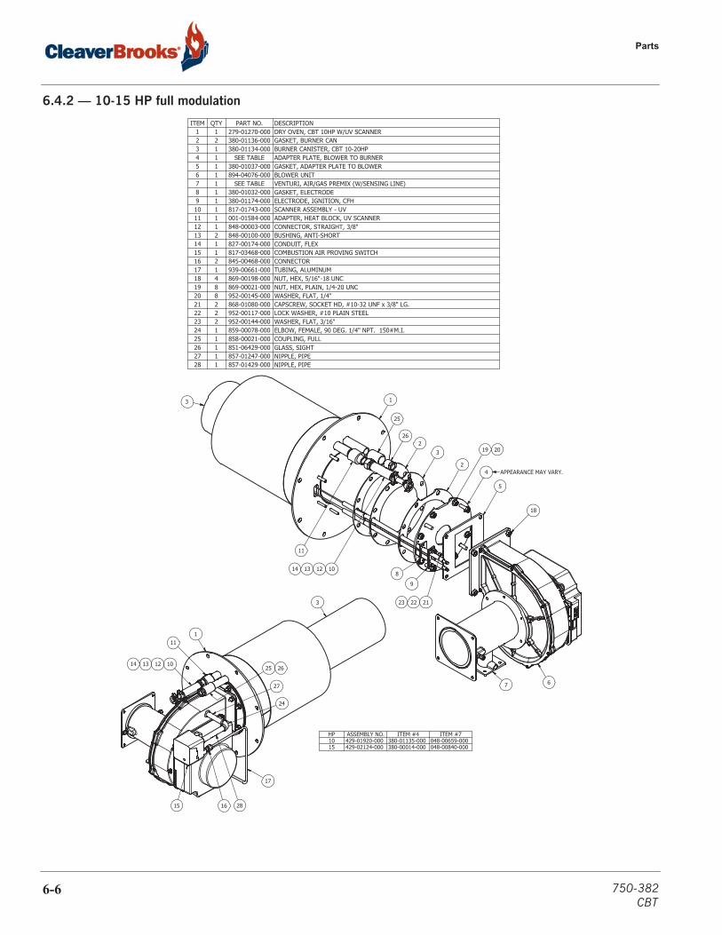
Parts
6.4.2 — 10-15 HP full modulation
DESCRIPTIONPART NO.QTYITEMDRY OVEN, CBT 10HP W/UV SCANNER279-01270-00011GASKET, BURNER CAN380-01136-00022BURNER CANISTER, CBT 10-20HP380-01134-00013ADAPTER PLATE, BLOWER TO BURNERSEE TABLE14GASKET, ADAPTER PLATE TO BLOWER380-01037-00015BLOWER UNIT894-04076-00016VENTURI, AIR/GAS PREMIX (W/SENSING LINE)SEE TABLE17GASKET, ELECTRODE380-01032-00018ELECTRODE, IGNITION, CFH380-01174-00019SCANNER ASSEMBLY - UV817-01743-000110ADAPTER, HEAT BLOCK, UV SCANNER001-01584-000111CONNECTOR, STRAIGHT, 3/8"848-00003-000112BUSHING, ANTI-SHORT848-00100-000213CONDUIT, FLEX827-00174-000114COMBUSTION AIR PROVING SWITCH817-03468-000115CONNECTOR845-00468-000216TUBING, ALUMINUM939-00661-000117NUT, HEX, 5/16"-18 UNC869-00198-000418NUT, HEX, PLAIN, 1/4-20 UNC869-00021-000819WASHER, FLAT, 1/4"952-00145-000820CAPSCREW, SOCKET HD, #10-32 UNF x 3/8" LG.868-01080-000221LOCK WASHER, #10 PLAIN STEEL952-00117-000222WASHER, FLAT, 3/16"952-00144-000223ELBOW, FEMALE, 90 DEG. 1/4" NPT. 150#M.I.859-00078-000124COUPLING, FULL858-00021-000125GLASS, SIGHT851-06429-000126NIPPLE, PIPE857-01247-000127NIPPLE, PIPE857-01429-000128
6
13
23
24
5
18
19 20
11
101213148
9
212223
7
26
25
APPEARANCE MAY VARY.
HP ASSEMBLY NO. ITEM #4 ITEM #710 429-01920-000 380-01135-000 048-00659-00015 429-02124-000 380-00014-000 048-00840-000
1
3
11
10121314
15 16
17
28
25 26
27
24
6-6 750-382CBT
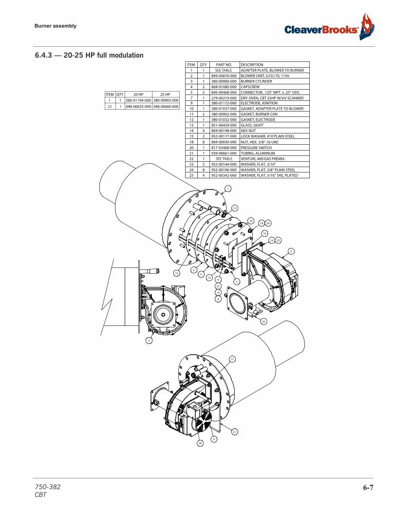
Burner assembly
6.4.3 — 20-25 HP full modulationDESCRIPTIONPART NO.QTYITEM
ITEM
ADAPTER PLATE, BLOWER TO BURNER
380-00903-000
11BLOWER UNIT, G1G170, 115V894-04076-00012BURNER CYLINDER380-00900-00013CAPSCREW868-01080-00024CONNECTOR, .125" MPT. x .25" ODC845-00468-00025DRY OVEN, CBT 25HP W/UV SCANNER279-00219-00017ELECTRODE, IGNITION380-01172-00019GASKET, ADAPTER PLATE TO BLOWER380-01037-000110GASKET, BURNER CAN380-00902-000211GASKET, ELECTRODE380-01032-000112GLASS, SIGHT851-06429-000113HEX NUT869-00198-000414LOCK WASHER, #10 PLAIN STEEL952-00117-000215NUT, HEX. 3/8"-16 UNC869-00030-000818PRESSURE SWITCH817-03468-000120TUBING, ALUMINUM939-00661-000121VENTURI, AIR/GAS PREMIX
048-00660-000
122WASHER, FLAT, 3/16"952-00144-000223WASHER, FLAT, 3/8" PLAIN STEEL952-00106-000824WASHER, FLAT, 5/16" SAE, PLATED952-00342-000425
5
21
17
520
13
129
23
15
4
113
11
22
1918 24
10
2
14 25
1
7
20 HP 25 HPQTY380-01194-00011
SEE TABLE
SEE TABLE
048-00655-00022 1
750-382CBT
6-7
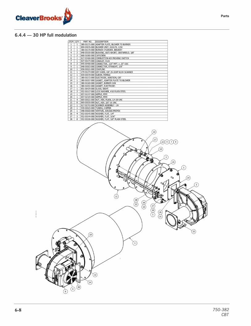
Parts
6.4.4 — 30 HP full modulation
6-8 750-382CBT

Burner assembly
6.4.5 — 40 HP full modulation
DESCRIPTIONPART NO.QTYITEMADAPTER PLATE, BLOWER TO BURNER380-00905-00011BLOWER UNIT, G3G200894-04111-00012BURNER CYLINDER, BEKAERT380-00904-00013CAPSCREW, SOCKET HD, #10-32 UNF x 3/8" LG.868-01080-00024COMBUSTION AIR PROVING SWITCH817-05607-00015CONNECTOR, .125" MPT. x .25" ODC845-00468-00026COUPLING, FULL, 1/2" NPT STD. WT. MERCHANT TYPE STEEL858-00021-00017DRY OVEN, CBT 40HP W/UV SCANNER279-00220-00018ELBOW, REDUCING, 1/4" NPS X 1/8" NPS847-00542-00019ELECTRODE, IGNITION380-00550-000110GASKET, ADAPTER PLATE TO BLOWER(380C01076)380-01076-000111GASKET, BURNER CAN380-01169-000212GASKET, ELECTRODE (DWG. 380-01032-000)380-01032-000113GLASS, SIGHT, 1/2" NPTF MALE, (DRYSEAL)851-06429-000114LOCK WASHER, #10 PLAIN STEEL952-00117-000215NIPPLE, PIPE, SMLS, 1/8" NPS x 5" LG. SCH.40, SA106 GR. B857-01633-000116NIPPLE, PIPE, SMLS, 1/4" NPS x 1-1/2" LG., SCH.80857-00726-000117HEX NUT, 5/16-18 UNC CAD PLATED ASTM A307 GR. A869-00198-000418NUT, HEX. 3/8"-16 UNC869-00030-000819TUBING, ALUMINUM, .25" O.D. x .035" WALL x 29" LG.939-02001-000120VENTURI, AIR/GAS PREMIX (W/SENSING LINE)SEE TABLE121WASHER, FLAT, 5/16" SAE, PLATED952-00342-000422WASHER, FLAT, 3/16"952-00144-000223WASHER, FLAT, 3/8" PLAIN STEEL952-00106-000824PLUG, PIPE, SQUARE HEAD, 1/8" NPT858-00088-000125
7
14
123
12 1
19 2425
1118 22
2
21
8 1310
4
15
23
16
17
9
6
20
5
FUEL ASSEMBLY NO. ITEM #21NAT GAS 429-00170-000 048-00662-000
LP 429-00194-000 048-00656-000
750-382CBT
6-9

Parts
6.4.6 — 50 HP full modulation
DESCRIPTIONPART NO.QTYITEMADAPTER PLATE, BLOWER TO BURNER380-00906-00011BLOWER UNIT, G3G250, 115V894-04075-00012BURNER CYLINDER, BEKAERT380-00904-00013CAPSCREW, SOCKET HD, #10-32 UNF x 3/8" LG.868-01080-00024COMBUSTION AIR PROVING SWITCH817-05607-00015CONNECTOR, .125" MPT. x .25" ODC845-00468-00026COUPLING, FULL, 1/2" NPT STD. WT. MERCHANT TYPE STEEL858-00021-00017DRY OVEN, CBT 40HP W/UV SCANNER279-00220-00018NIPPLE, PIPE, SMLS, 1/4" NPS x 3" LG., SCH.80857-00679-00019ELECTRODE, IGNITION380-00550-000110GASKET, ADAPTER PLATE TO BLOWER (380C01038)380-01038-000111GASKET, BURNER CAN380-01169-000212GASKET, ELECTRODE (DWG. 380-01032-000)380-01032-000113GLASS, SIGHT, 1/2" NPTF MALE, (DRYSEAL)851-06429-000114LOCK WASHER, #10 PLAIN STEEL952-00117-000215HEX NUT, 5/16-18 UNC CAD PLATED ASTM A307 GR. A869-00198-000416WASHER, FLAT, 5/16" SAE, PLATED952-00342-000417NUT, HEX. 3/8"-16 UNC869-00030-000818TUBING, ALUMINUM, 1/4" O.D. x .035" WALL x 24.25" LG.939-02001-000119VENTURI, AIR/GAS PREMIX (W/SENSING LINE)048-00662-000120WASHER, FLAT, 3/16"952-00144-000221WASHER, FLAT, 3/8" PLAIN STEEL952-00106-000822VANE, VORTEX BREAKER, PROPANE (NOT SHOWN)197-00623-000TABLE23
7
14
12
3
121 18 22
8 13
104
15
21
1116 17
20
2
9
5619
23
FUEL ASSEMBLY NO. QTYNAT GAS 429-00181-000 0
LP 429-00182-000 1
6-10 750-382CBT

Burner assembly
Continue to next page
750-382CBT
6-11

Parts
Continue to next page
6-12 750-382CBT
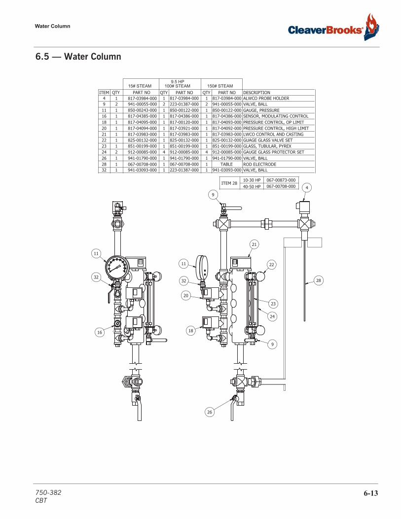
Water Column
6.5 — Water Column
49
26
24
23
21
20
18
32
11
16
28
9
32
11
22
DESCRIPTIONPART NOPART NO QTYQTYITEMALWCO PROBE HOLDER817-03984-00014VALVE, BALL941-00055-00029GAUGE, PRESSURE850-00122-000111SENSOR, MODULATING CONTROL817-04386-000116PRESSURE CONTROL, OP LIMIT817-04093-000118PRESSURE CONTROL, HIGH LIMIT817-04092-000120LWCO CONTROL AND CASTING817-03983-000121GUAGE GLASS VALVE SET825-00132-000122GLASS, TUBULAR, PYREX851-00199-000123GAUGE GLASS PROTECTOR SET912-00085-000424VALVE, BALL941-01790-000126ROD ELECTRODE TABLE128VALVE, BALL941-03093-000132
150# STEAMPART NOQTY
817-03984-0001223-01387-0002850-00122-0001817-04386-0001817-00120-0001817-03921-0001817-03983-0001825-00132-0001851-00199-0001912-00085-0004941-01790-0001067-00708-0001223-01387-0001
100# STEAM9.5 HP
817-03984-0001941-00055-0002850-00243-0001817-04385-0001817-04095-0001817-04094-0001817-03983-0001825-00132-0001851-00199-0001912-00085-0002
067-00708-0001941-01790-0001
941-03093-0001
15# STEAM
ITEM 28 10-30 HP40-50 HP 067-00708-000
067-00873-000
750-382CBT
6-13
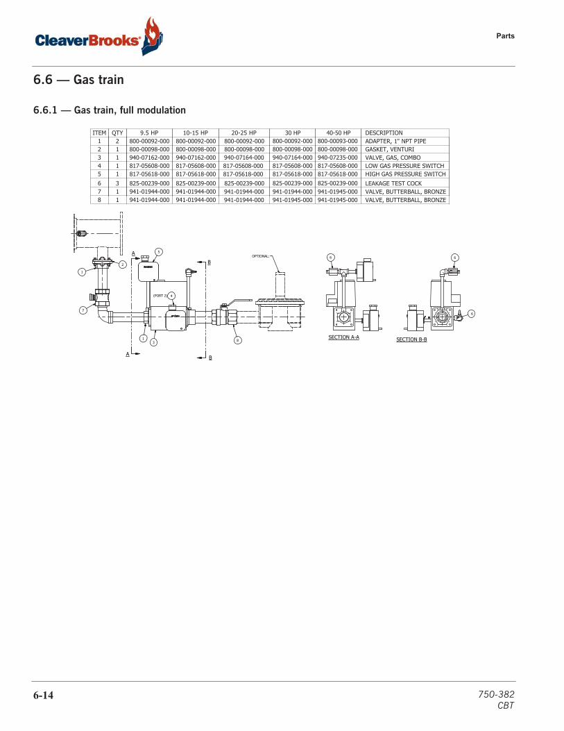
Parts
6.6 — Gas train
6.6.1 — Gas train, full modulation
SECTION A-A SECTION B-B
A
A
B
B
6
6
6
83
7
2
1
OPTIONAL:
4(PORT 2)
5
1
DESCRIPTION10-15 HP 20-25 HPQTYITEMADAPTER, 1" NPT PIPE800-00092-000 800-00092-00021GASKET, VENTURI800-00098-000 800-00098-00012VALVE, GAS, COMBO940-07162-000
9.5 HP800-00092-000800-00098-000940-07162-000 940-07164-00013
LOW GAS PRESSURE SWITCH817-05608-00014HIGH GAS PRESSURE SWITCH817-05618-000
817-05608-000817-05618-000
817-05608-000817-05618-00015
LEAKAGE TEST COCK825-00239-000 825-00239-00036VALVE, BUTTERBALL, BRONZE941-01944-000
817-05608-000817-05618-000825-00239-000941-01944-000 941-01944-000
30 HP800-00092-000800-00098-000940-07164-000
825-00239-000941-01944-000
40-50 HP800-00093-000800-00098-000940-07235-000817-05608-000817-05618-000825-00239-000941-01945-00017
VALVE, BUTTERBALL, BRONZE941-01944-000941-01944-000 941-01944-000 941-01945-000 941-01945-00018
6-14 750-382CBT
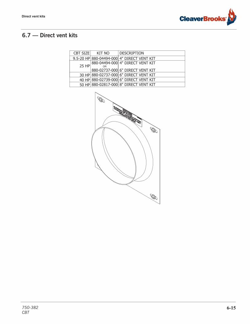
Direct vent kits
6.7 — Direct vent kits
DESCRIPTIONKIT NO4" DIRECT VENT KIT 880-04494-0004" DIRECT VENT KIT880-04494-000
CBT SIZE9.5-20 HP
25 HP6" DIRECT VENT KIT6" DIRECT VENT KIT
880-02737-000880-02737-00030 HP
OR
6" DIRECT VENT KIT880-02739-00040 HP8" DIRECT VENT KIT880-02817-00050 HP
750-382CBT
6-15


APPENDIX A
CB Falcon Controller


INSTALLATION AND OPERATION
APPLICATION
The CB Falcon is a boiler control system available for hydronic or steam applications. The Falcon is able to provide heat control, flame supervision, circulation pump control, fan control, boiler modulation control, and electric ignition function. It will also provide boiler status and error reporting.
Multiple boilers can be joined together to heat a system instead of a single, larger burner or boiler. Using boilers in parallel is more efficient, costs less, reduces emissions, improves load control, and is more flexible than the traditional large boiler.
CB Falcon system may consist of:833-3639/3871/4086 or 833-3578 Control DeviceTouchscreen Display—required for user interface and Modbus communication.Flame Rod or UV flame sensorTemperature Sensor, NTC TypeLimit Sensor, NTC Type, dual element833-3578 uses a Steam Pressure Sensor, 0-15 or 0-150 psi - 4-20mA source type
CB Falcon Boiler Control System833-3578 Steam 833-3639, 833-4086 & 833-3871 Hydronic
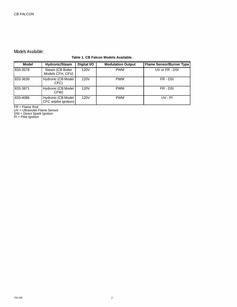
CB FALCON
750-265 2
Models Available:
FR = Flame RodUV = Ultraviolet Flame SensorDSI = Direct Spark IgnitionPI = Pilot Ignition
Table 1. CB Falcon Models Available.
Model Hydronic/Steam Digital I/O Modulation Output Flame Sensor/Burner Type833-3578 Steam (CB Boiler
Models CFH, CFV)120V PWM UV or FR - DSI
833-3639 Hydronic (CB Model CFC)
120V PWM FR - DSI
833-3871 Hydronic (CB Model CFW)
120V PWM FR - DSI
833-4086 Hydronic (CB Model CFC w/pilot ignition)
120V PWM UV - PI

CB FALCON
3 750-265
TABLE OF CONTENTSFeatures - - - - - - - - - - - - - - - - - - - - - - - - - - - - - - - - - - - - - - - - - - - - - - - - - - - - - - - - - - - - 4Operational Features - - - - - - - - - - - - - - - - - - - - - - - - - - - - - - - - - - - - - - - - - - - - - - - - - - - 5Communications and Displays - - - - - - - - - - - - - - - - - - - - - - - - - - - - - - - - - - - - - - - - - - - 8Specifications - - - - - - - - - - - - - - - - - - - - - - - - - - - - - - - - - - - - - - - - - - - - - - - - - - - - - - - - 9Installation - - - - - - - - - - - - - - - - - - - - - - - - - - - - - - - - - - - - - - - - - - - - - - - - - - - - - - - - - - 10Wiring - - - - - - - - - - - - - - - - - - - - - - - - - - - - - - - - - - - - - - - - - - - - - - - - - - - - - - - - - - - - - - 10Startup - - - - - - - - - - - - - - - - - - - - - - - - - - - - - - - - - - - - - - - - - - - - - - - - - - - - - - - - - - - - - - 18Pump Control - - - - - - - - - - - - - - - - - - - - - - - - - - - - - - - - - - - - - - - - - - - - - - - - - - - - - - - - 53Annunciator - - - - - - - - - - - - - - - - - - - - - - - - - - - - - - - - - - - - - - - - - - - - - - - - - - - - - - - - - - 61Fault Handling - - - - - - - - - - - - - - - - - - - - - - - - - - - - - - - - - - - - - - - - - - - - - - - - - - - - - - - - 63Burner Control Operation - - - - - - - - - - - - - - - - - - - - - - - - - - - - - - - - - - - - - - - - - - - - - - - 64System Checkout - - - - - - - - - - - - - - - - - - - - - - - - - - - - - - - - - - - - - - - - - - - - - - - - - - - - - 65Initial Lightoff Checks - - - - - - - - - - - - - - - - - - - - - - - - - - - - - - - - - - - - - - - - - - - - - - - - - - 66pilot Turndown Test - - - - - - - - - - - - - - - - - - - - - - - - - - - - - - - - - - - - - - - - - - - - - - - - - - - - 68ignition Interference Test - - - - - - - - - - - - - - - - - - - - - - - - - - - - - - - - - - - - - - - - - - - - - - - - 69Hot Refractory Hold-In Test - - - - - - - - - - - - - - - - - - - - - - - - - - - - - - - - - - - - - - - - - - - - - - 69Ignition Spark Response Test - - - - - - - - - - - - - - - - - - - - - - - - - - - - - - - - - - - - - - - - - - - - 69Safety Shutdown Tests - - - - - - - - - - - - - - - - - - - - - - - - - - - - - - - - - - - - - - - - - - - - - - - - - 70Troubleshooting - - - - - - - - - - - - - - - - - - - - - - - - - - - - - - - - - - - - - - - - - - - - - - - - - - - - - - 71Lead Lag - - - - - - - - - - - - - - - - - - - - - - - - - - - - - - - - - - - - - - - - - - - - - - - - - - - - - - - - - - - - 72Appendix A: Parameter Glossary - - - - - - - - - - - - - - - - - - - - - - - - - - - - - - - - - - - - - - - - - 89Appendix B: Hydronic Device Parameter Worksheet Example - - - - - - - - - - - - - - - - - - - - 100Appendix C: Lockout and Hold Codes - - - - - - - - - - - - - - - - - - - - - - - - - - - - - - - - - - - - - - 105
This manual is intended to provide a general overview of the CB Falcon hydronic and steam controls. The chosen set of parameters for a certain boiler type needs to be functionally tested for correct operation. Certain controllers are factory configured for specific boiler models.
This document is a textbook version of the parameters. The glossary beginning on page 89 provides an abbreviated parameter explanation along with a reference page for a more in-depth explanation.
The actual setup of the hydronic or steam control is accomplished using the 833-3577 System Operator Interface. Refer to manual 750-241 for the operation and setup screens. This document will assist in understanding the parameters being set up. The manual contains a worksheet example of Falcon device parameters and how they might be set up to provide a functioning system.
Note that while the worksheet shows most parameters as being available, the actual product may have parameters made invisible or read-only by the OEM, as applicable to specific boiler models.
The chosen set of parameters for a certain boiler type MUST be functionally tested for correct operation.
Access codes allow for different levels of setup:
— The OEM level allows for equipment to operate within guidelines that they feel necessary for safe and effi-cient operation of their equipment. The OEM makes available the parameters that the installing contractor needs for installation adjustments of the equipment.
— The installer setup information is customized by the OEM. The access code for the installer level must be obtained from the OEM.
— The User level allows for non critical adjustments for the individual piece of equipment. User-permitted actions include but are not limited to:
• Read the error log.• Monitor the input and output variables of the
controller.• Read parameters.• CH and DHW setpoint adjustment.

CB FALCON
750-265 4
FEATURESSafety and Boiler ProtectionHydronic Control• Frost Protection, Slow Start, Anti-condensate, Boiler Delta-
T, Stack Limit, Boiler Limit, DHW Limit, Outlet T-Rise LimitSteam Control• Slow Start, Stack Limit
Integrated Control Functions• Primary Flame Safeguard Control• Internal or external spark generator• Algorithm Prioritization• Firing Rate Limiting
• Hydronic Control• Anti-Condensate, Stack Limit, Boiler Delta-T,• Boiler Slow Start, Outlet Limit
• Steam Control• Stack Limit
• PID Load Control• Hydronic Control
• CH (Central Heat)• DHW (Domestic Hot Water)
• Steam Control• Steam
• Remote Reset• TOD (Time of Day)• PWM for Variable Frequency Drives• Auxiliary Output Control
• Hydronic Control for Pumps• 3 outputs, 5 different programmable
features)• Steam Control
• 3 programmable output features• Burner Demand sources
• Hydronic Control• CH, DHW and Frost Protection
• Steam Control• Steam sensor
• Loops of Control• Hydronic Control has two loops of Control
• CH• DHW
• Steam Control has One loop of Control• Steam
• High Limit and Control (Meets UL 353)• Hydronic Control• CH, DHW and Stack
• Steam Control• Stack
• Fifteen Item Fault Code History including equipment status at time of lockout
• Fifteen Item Alert Code Status including equipment status at time of internal alerts
• 24Vac Device Power• Hydronic: 24 or 120Vac Digital I/O models available.• Steam: 120Vac Digital I/O• Flame Signal test jacks (Vdc)• Three Status LEDs
• Power
• Flame• Alarm
• Flame Sensing• Ultraviolet (C7027, C7035, C7044 Sensors)• Flame Rod
• Single Element (Internal spark generator and flame sense using the same element)
• Dual Element (separate elements for ignition spark and flame sense)
Inputs• Analog Inputs
• NTC Sensor Inputs (10kohm or 12kohm)NOTE:12kohm and 10kohm single sensors cannot be
used for Limit Application functions (10kohm dual sensors only).
• Hydronic Control• Outlet Limit And Temperature• DHW Limit and Temperature• Stack Limit and Temperature• Inlet Temperature• Outdoor Temperature
• Steam Control• Stack Limit and Temperature
• Other Analog Inputs• PWM Feedback• Flame Signal from either a Flame Rod or
Ultraviolet Detector• 4-20mA Control Input, Remote Setpoint,
Remote Firing Rate• 4-20mA Steam Input Pressure (15 or 150
psi)• Digital Inputs
• Pre Ignition Interlock (Programmable)• LCI (Load [or Limit] Control Input) (Programmable)• Interlock (Programmable)• Annunciation (8 Programmable) (6 Programmable
plus High Fire and Low Fire Switch Interlocks—model specific)
• Remote Reset• TOD (Time of Day)
Outputs• Analog Outputs
• Modulation• 4-20mA• 0-10 Vdc• PWM for Variable Frequency Drives
• Digital Outputs• Auxiliary Output Control
• Hydronic Control for Pumps3 outputs, 5 different programmable features)
• Steam Control3 programmable output features
• Combustion Blower• External Ignition• Pilot Valve• Main Valve• Alarm
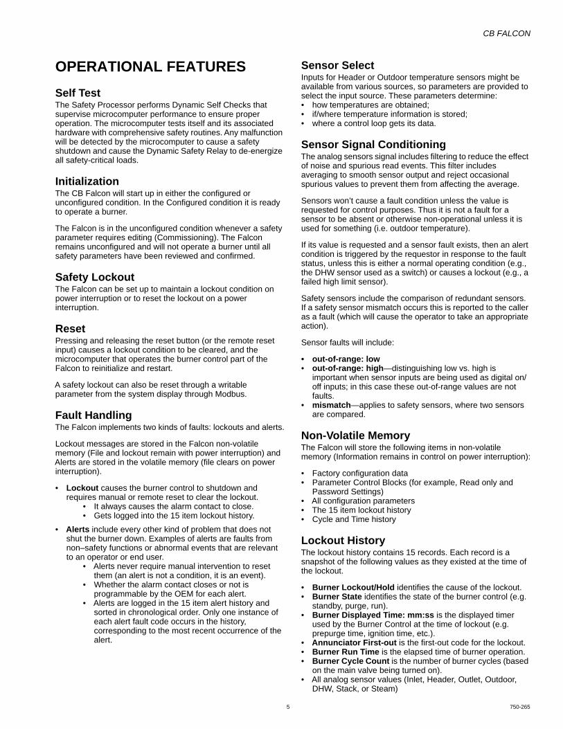
CB FALCON
5 750-265
OPERATIONAL FEATURESSelf TestThe Safety Processor performs Dynamic Self Checks that supervise microcomputer performance to ensure proper operation. The microcomputer tests itself and its associated hardware with comprehensive safety routines. Any malfunction will be detected by the microcomputer to cause a safety shutdown and cause the Dynamic Safety Relay to de-energize all safety-critical loads.
InitializationThe CB Falcon will start up in either the configured or unconfigured condition. In the Configured condition it is ready to operate a burner.
The Falcon is in the unconfigured condition whenever a safety parameter requires editing (Commissioning). The Falcon remains unconfigured and will not operate a burner until all safety parameters have been reviewed and confirmed.
Safety LockoutThe Falcon can be set up to maintain a lockout condition on power interruption or to reset the lockout on a power interruption.
ResetPressing and releasing the reset button (or the remote reset input) causes a lockout condition to be cleared, and the microcomputer that operates the burner control part of the Falcon to reinitialize and restart.
A safety lockout can also be reset through a writable parameter from the system display through Modbus.
Fault HandlingThe Falcon implements two kinds of faults: lockouts and alerts.
Lockout messages are stored in the Falcon non-volatile memory (File and lockout remain with power interruption) and Alerts are stored in the volatile memory (file clears on power interruption).
• Lockout causes the burner control to shutdown and requires manual or remote reset to clear the lockout.
• It always causes the alarm contact to close.• Gets logged into the 15 item lockout history.
• Alerts include every other kind of problem that does not shut the burner down. Examples of alerts are faults from non–safety functions or abnormal events that are relevant to an operator or end user.
• Alerts never require manual intervention to reset them (an alert is not a condition, it is an event).
• Whether the alarm contact closes or not is programmable by the OEM for each alert.
• Alerts are logged in the 15 item alert history and sorted in chronological order. Only one instance of each alert fault code occurs in the history, corresponding to the most recent occurrence of the alert.
Sensor SelectInputs for Header or Outdoor temperature sensors might be available from various sources, so parameters are provided to select the input source. These parameters determine:• how temperatures are obtained;• if/where temperature information is stored;• where a control loop gets its data.
Sensor Signal ConditioningThe analog sensors signal includes filtering to reduce the effect of noise and spurious read events. This filter includes averaging to smooth sensor output and reject occasional spurious values to prevent them from affecting the average.
Sensors won’t cause a fault condition unless the value is requested for control purposes. Thus it is not a fault for a sensor to be absent or otherwise non-operational unless it is used for something (i.e. outdoor temperature).
If its value is requested and a sensor fault exists, then an alert condition is triggered by the requestor in response to the fault status, unless this is either a normal operating condition (e.g., the DHW sensor used as a switch) or causes a lockout (e.g., a failed high limit sensor).
Safety sensors include the comparison of redundant sensors. If a safety sensor mismatch occurs this is reported to the caller as a fault (which will cause the operator to take an appropriate action).
Sensor faults will include:
• out-of-range: low• out-of-range: high—distinguishing low vs. high is
important when sensor inputs are being used as digital on/off inputs; in this case these out-of-range values are not faults.
• mismatch—applies to safety sensors, where two sensors are compared.
Non-Volatile MemoryThe Falcon will store the following items in non-volatile memory (Information remains in control on power interruption):
• Factory configuration data• Parameter Control Blocks (for example, Read only and
Password Settings)• All configuration parameters• The 15 item lockout history• Cycle and Time history
Lockout HistoryThe lockout history contains 15 records. Each record is a snapshot of the following values as they existed at the time of the lockout.
• Burner Lockout/Hold identifies the cause of the lockout.• Burner State identifies the state of the burner control (e.g.
standby, purge, run).• Burner Displayed Time: mm:ss is the displayed timer
used by the Burner Control at the time of lockout (e.g. prepurge time, ignition time, etc.).
• Annunciator First-out is the first-out code for the lockout.• Burner Run Time is the elapsed time of burner operation.• Burner Cycle Count is the number of burner cycles (based
on the main valve being turned on).• All analog sensor values (Inlet, Header, Outlet, Outdoor,
DHW, Stack, or Steam)
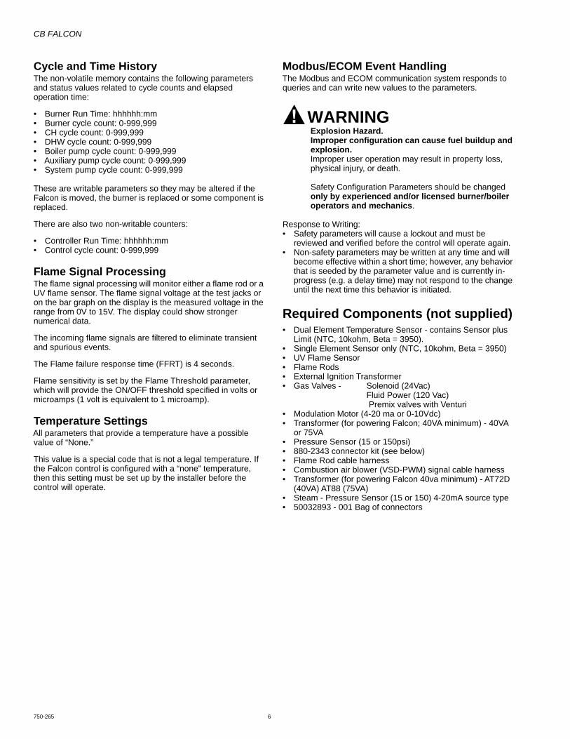
CB FALCON
750-265 6
Cycle and Time HistoryThe non-volatile memory contains the following parameters and status values related to cycle counts and elapsed operation time:
• Burner Run Time: hhhhhh:mm• Burner cycle count: 0-999,999• CH cycle count: 0-999,999• DHW cycle count: 0-999,999• Boiler pump cycle count: 0-999,999• Auxiliary pump cycle count: 0-999,999• System pump cycle count: 0-999,999
These are writable parameters so they may be altered if the Falcon is moved, the burner is replaced or some component is replaced.
There are also two non-writable counters:
• Controller Run Time: hhhhhh:mm• Control cycle count: 0-999,999
Flame Signal ProcessingThe flame signal processing will monitor either a flame rod or a UV flame sensor. The flame signal voltage at the test jacks or on the bar graph on the display is the measured voltage in the range from 0V to 15V. The display could show stronger numerical data.
The incoming flame signals are filtered to eliminate transient and spurious events.
The Flame failure response time (FFRT) is 4 seconds.
Flame sensitivity is set by the Flame Threshold parameter, which will provide the ON/OFF threshold specified in volts or microamps (1 volt is equivalent to 1 microamp).
Temperature SettingsAll parameters that provide a temperature have a possible value of “None.”
This value is a special code that is not a legal temperature. If the Falcon control is configured with a “none” temperature, then this setting must be set up by the installer before the control will operate.
Modbus/ECOM Event HandlingThe Modbus and ECOM communication system responds to queries and can write new values to the parameters.
WARNINGExplosion Hazard.Improper configuration can cause fuel buildup and explosion.Improper user operation may result in property loss, physical injury, or death.
Safety Configuration Parameters should be changed only by experienced and/or licensed burner/boiler operators and mechanics.
Response to Writing:• Safety parameters will cause a lockout and must be
reviewed and verified before the control will operate again.• Non-safety parameters may be written at any time and will
become effective within a short time; however, any behavior that is seeded by the parameter value and is currently in-progress (e.g. a delay time) may not respond to the change until the next time this behavior is initiated.
Required Components (not supplied)• Dual Element Temperature Sensor - contains Sensor plus
Limit (NTC, 10kohm, Beta = 3950). • Single Element Sensor only (NTC, 10kohm, Beta = 3950)• UV Flame Sensor• Flame Rods• External Ignition Transformer• Gas Valves - Solenoid (24Vac)
Fluid Power (120 Vac) Premix valves with Venturi
• Modulation Motor (4-20 ma or 0-10Vdc)• Transformer (for powering Falcon; 40VA minimum) - 40VA
or 75VA• Pressure Sensor (15 or 150psi)• 880-2343 connector kit (see below)• Flame Rod cable harness• Combustion air blower (VSD-PWM) signal cable harness• Transformer (for powering Falcon 40va minimum) - AT72D
(40VA) AT88 (75VA)• Steam - Pressure Sensor (15 or 150) 4-20mA source type• 50032893 - 001 Bag of connectors

CB FALCON
7 750-265
880-2343 Connector Kit
Device Mates with …Plug # Description Manf. Part Number
J1 Flame Detection Interface
Molex 0050841060 (Shell), 0002082004 (Pin, 14-20 AWG)
J2 PWM Combustion Blower Interface
Molex 0039012040 (Shell), 0039000059 (Pin, 18-24 AWG)
J3 Comm. Interface OST EDZ1100/9 (SCREW)J4 Line Voltage I/O Lumberg 3623 06 K129 (IDC, Pins 1 - 6) 3615-1 06 K129 (SCREW, Pins 1 - 6)
3623 06 K130 (IDC, Pins 7 - 12) 3615-1 06 K130 (SCREW, Pins 7 - 12)J5 Line Voltage I/O Lumberg 3623 07 K01 (IDC) 3615-1 07 K01 (SCREW)J6 Line Voltage I/O Lumberg 3623 08 K43 (IDC) 3615-1 04 K185 (SCREW, Pins 1- 4)
3615-1 04 K188 (SCREW, Pins 5- 8)J7 Line Voltage I/O Lumberg 3623 07 K48 (IDC) 3615-1 07 K48 (SCREW)J8 Low Voltage I/O Lumberg 3623 06 K127 (IDC, Pins 1 - 6) 3615-1 06 K127 (SCREW, Pins 1 - 6)
3623 06 K128 (IDC, Pins 7 - 12) 3615-1 06 K128 (SCREW, Pins 7 - 12)J9 Low Voltage I/O Lumberg 3623 07 K59 (IDC) 3615-1 07 K59 (SCREW)J10 High Voltage I/O Lumberg 3623 08 K64 (IDC) 3615-1 04 K187 (SCREW, Pins 1- 4)
3615-1 04 K186 (SCREW, Pins 5- 8)J11 High Voltage I/O Lumberg 3623 07 K30 (IDC) 3615-1 07 K30 (SCREW)

CB FALCON
750-265 8
OVERVIEWFunctions provided by the Falcon include automatic boiler sequencing, flame supervision, system status indication, firing rate control, load control, CH/DHW control, limit control, system or self-diagnostics and troubleshooting.
The maximum version of the controller offers:
• NTC-temperature sensor for:• Outlet Limit And Temperature• DHW (Domestic Hot Water) Limit and Temperature• Stack Temperature Limit and Temperature• Inlet Temperature• Outdoor Temperature (hydronic only)
• Modulating output PWM-driven rotation speed controlled DC-fan for optimal modulation control.
• Three Pump Outputs with 5 selectable operation modes• 24Vac or 120Vac (model specific) offer:
• Output control of gas valve (Pilot and Main) and External Ignition Transformer
• Digital inputs for room limit control, high limit control, Air pressure switch, Gas pressure switch, low water cutoff, valve proof of closure switch.
• Optional switches:• Time of Day switch
• Burner switch
• Remote Reset
• Easy modification of the parameters on three levels:• End-user
• Installer / Service engineer
• Manufacturer
• Integrated spark transformer• Optional external spark transformer• Optional combined ignition and flame sensing• Test jacks for flame signal measurement from either a flame
rod or UV flame sensor.• Alarm Output
Fig. 1. General Falcon hydronic boiler schematic.
Fig. 1 shows two loops of heat control: Central Heating (CH), and an optional second loop for Domestic Hot Water (DHW) can be configured on each Falcon. The DHW loop transfers heat from the boiler outlet to hot water appliances in conjunction with the primary system heat loop. Priority assignment to each heat loop can be configured to specify which loop gets serviced first.
COMMUNICATIONS AND DISPLAYS• The Falcon has two RS485 communication ports for
Modbus that allows for interfacing to one or all Falcons in a system and presents them individually to the user. The
System Operator interface is used for configuration and monitoring of the CB Falcon. Control operation and display status in both test and graphical modes can be shown. The Falcon can also be remotely reset through the display.
• Either Modbus RS485 communication port can be used to allow configuration and status data to be read and written to the controller. A Building Automation master can control the Falcon to respond to requests in a Lead/Lag arrangement.
Falcon
HEATLOAD
T
OUTDOORTEMP
T
HEADERTEMP
IGNITOR
FAN
ALARM
STACK
T
T
BOILER
OUTLET
T
T
INLET
FLAME SIGNAL
INTERLOCK(S)
PII
LIMIT(S)
ANNUNCIATION (8)
REMOTE RESET
TOD
STAT
PILOT VALVE
MAIN VALVE(S)
DOMESTICHOT WATERTANK
BOILERMIXLOOP
DHWLOOP
M27058
BUILDINGAUTOMATIONSYSTEM
WATEROUTPUTSINPUTS
KEYCOMMUNICATION
SYSTEMDISPLAY
CHLOOP

CB FALCON
9 750-265
SPECIFICATIONSElectrical Ratings:Operating voltage
24Vac (20 to 30 Vac, 60 Hz ±5%)Connected Load for Valve and annunciator functions:
24Vac, 60Hz120Vac (+10%/-15%), 60Hz (±5%)Model Specific
Corrosion:Falcon should not be used in a corrosive environment.
Operating Temperature: -4°F to 150°F (-20°C to 66°C)
Storage/Shipping Temperature: -40°F to 150°F(-40°C to 66°C).
Humidity:Up to 95% Relative Humidity, noncondensing at 104°F for 14
days. Condensing moisture may cause safety shutdown.
Vibration: 0.0 to 0.5g Continuous (V2 level)
Enclosure: Nema 1/IP40.
Approvals:Underwriters Laboratories, Inc. Component Recognized: File
No. MP268 (MCCZ). 833-3639 and 833-3578 are certified as UL372 Primary Safety Controls. 833-3639 is rated as a UL353 limit-rated device when using the dual element limit-rated NTC sensors.
CSD-1:Meets CSD-1 section CF-300 requirements as a Primary
Safety Control.Meets CSD-1 section CW-400 requirements as a Temperature
Operation control.Meets CSD-1 section CW-400 requirements as a Temperature
High Limit Control when configured for use with 10kohm NTC sensors.
Federal Communications Commission, Part 15,Class B.Emissions.
Dimensions: See Fig. 2.
Fig. 2. Falcon dimensions in in. (mm).
[2] 5-19/64 (135)
9-21/64(237) MAX
[4] Ø 3/16 (5) MAX
2-19/32 (66)
6-21/64 (161)
[2] 8-21/32(220)

CB FALCON
750-265 10
*Sensors attached to the Falcon MUST be all 12K or 10K sen-sors (don't mix and match).
INSTALLATION
WARNINGFire or Explosion Hazard. Can cause property damage, severe injury, or death.To prevent possible hazardous boiler operation, verify safety requirements each time a control is installed on a boiler.
WARNINGElectrical Shock Hazard.Can cause severe injury, death or property damage.Disconnect the power supply before beginning installation to prevent electrical shock and equipment damage. More than one power supply disconnect can be involved.
When Installing This Product…1. Read these instructions carefully. Failure to follow them
could damage the product or cause a hazardous condi-tion.
2. Refer to the wiring diagram provided as part of the appli-ance or refer to Fig. 3.
3. Check the ratings given in the instructions and on the product to make sure that the product is suitable for your application.
4. Installer must be a trained, experienced combustion ser-vice technician.
5. Disconnect the power supply before beginning installa-tion to prevent electrical shock and equipment damage. More than one disconnect may be involved.
6. All wiring must comply with applicable local electrical codes, ordinances and regulations.
7. After installation is complete, check out product opera-tion as provided in these instructions.
Vibration
Do not install the relay module where it could be subjected to vibration in excess of 0.5G continuous maximum vibration.
Weather
The relay module is not designed to be weather-tight. When installed outdoors, protect the relay module using an approved weather-tight enclosure.
Mounting The Falcon1. Select a location on a wall, burner or electrical panel.
The Falcon can be mounted directly in the control cabi-net. Be sure to allow adequate clearance for servicing.
2. Use the Falcon as a template to mark the four screw locations. Drill the pilot holes.
3. Securely mount the Falcon using four no. 6 screws.
NOTE: The device can be removed and replaced in the field without rewiring.
WIRING
WARNINGElectrical Shock Hazard.Can cause serious injury, death or property damage.Disconnect power supply before beginning wiring to prevent electrical shock and equipment damage. More than one disconnect may be involved.
Ground ConnectionThe ground connection on the controller must not be used as a central ground connection for the 120 Vac connections.
1. Use the common ground terminal next to the controller, close to connector J4 terminal 12.
2. Connect the central ground terminal with the connection contact of the controller (connector J4 terminal 12).
3. Connect the ground wire of the main power connector, the CH pump, the DHW pump (if present) and the igni-tion wire to the central ground terminal.
Electrical Connections1. Refer to Table 4 for terminal contact ratings.2. Use 18 AWG or larger wires.3. Wire according to specifications, following all local ordi-
nances and requirements.
Device Power Supply, 24Vac1. 24Vac Supply to connector J8 terminal 1.2. 24Vac Return to connector J8 terminal 2.
Table 1. NTC Sensors (temperature versus resistance).
Temp C (F)12K NTC (kOhm)*
Beta of 375010K NTC (kOhm)*
Beta of 3950-30 (-22) 171.70 176.08-20 (-4) 98.82 96.81-10 (14) 58.82 55.250 (32) 36.10 32.6410 (50) 22.79 19.9020 (68) 14.77 12.4925 (77) 12.00 10.0030 (86) 9.81 8.0640 (104) 6.65 5.3250 (122) 4.61 3.6060 (140) 3.25 2.4970 (158) 2.34 1.7580 (176) 1.71 1.2690 (194) 1.27 0.92100 (212) 0.95 0.68110 (230) 0.73 0.51120 (248) 0.56 0.39

CB FALCON
11 750-265
3. Ground to central ground terminal, not to Ground onJ4 terminal 12.
Limit String and Annunciator inputs and Safety Load Outputs
1. Wiring to connectors J4, J5, J6 and J7.2. Line Voltage (120Vac) or Low Voltage (24Vac) by model
number.
Dry Contacts available for:1. Pump A: Connector J4 terminal 6 & 7.2. Pump B: Connector J4 terminal 4 & 5.3. Pump C: Connector J4 terminal 2 & 3.4. Blower: Connector J5 terminal 6 & 7.5. Alarm: Connector J6 terminal 7 & 8.
Wiring Connectors J2, J8, J9, and J10Low Voltage Connections(includes NTC Sensor Inputs, 4 to 20 mA Input, PWM Combustion Blower Motor output, combustion blower speed (tachometer) input, Remote and TOD reset, current and voltage outputs)
1. Wire according to specifications, following all local ordi-nances and requirements.
2. Do not bundle the low voltage wires with the ignition cable, 120 Vac wires, CH Pump or DHW Pump.
3. Bundle the wires for the fan and join them with the other 24V low-voltage wires.
4. Bundle the wires for the NTC sensors and the PWM combustion blower control separately.
High Voltage Cable1. Always use a grommet when placing the high voltage
cable through a sheet metal panel.2. Never join the high voltage cable with other wires.
• Be sure that there is a good electrical return path between the Falcon and sparking electrode (ground connection).
• A short ignition wire normally leads to lower levels of radiated electromagnetic fields.
• Use a Spark cable (32004766 or R1298020) or equivalent.• Heat-resistant up to 248°F (120°C).• Isolation voltage up to 25 kV DC.
Note that the high voltage ignition spark, the high voltage ignition lead and the return path of the current that flows during sparking is an important source of electromagnetic interference.
A ground return wire is required in the appliance to reduce the high frequency components of the actual return current.
Communications: Connector J31. The ECOM port - connectors J3 terminal 1, J3 terminal
2, J3 terminal 3 - is not used in CB Falcon aplications Do not connect the display to these connectors.
2. Connect the 833-3577/3725 Display to either J3 Modbus port (MB1 or MB2), connectors a, b, c.
Flame Signal: Connector J11. Flame Rod: Single Element
a. Connect the Flame rod for both ignition spark and flame sense to the ignition transformer terminal.
b. Connect the Flame rod ground to connector J1 termi-nal 3.
c. Install a jumper between connector J1 terminal 1 and terminal 2.
2. Flame Rod: Dual Element (separate elements for ignition spark and flame sense)a. Connect the Flame rod sense lead to connector J1
terminal 2.b. Connect the Flame rod ground to connector J1 termi-
nal 3.c. Do not route the Flame rod sense lead wire or
ground wire near the ignition spark high-voltage cable or other line voltage wiring.
UV Flame Detection1. Connect the UV Flame detector sense lead (blue wire) to
connector J1 terminal 4.2. Connect the UV Flame detector ground lead (white wire)
to connector J1 terminal 6.3. Do not route the UV Flame detector wiring near the igni-
tion spark high-voltage cable or other line voltage wiring.
Final Wiring Check1. Check the power supply circuit. The voltage and fre-
quency tolerance must match those of the Falcon. A separate power supply circuit may be required for the Falcon. Add the required disconnect means and over-load protection.
2. Check all wiring circuits.3. Install all electrical connectors.4. Restore power to the panel.
The Falcon can be removed and replaced in the field without requiring re-wiring.
The lengths of the wires and electrical ratings for each terminal are specified in Table 4 on page 15.
Table 2. Wire Sizes.
Application Recommended Wire Size Recommended Part Number(s)
Maximum Leadwire
Distance (in feet)
Line Voltage Terminals
14, 16, 18 AWG Copper conductor, 600 volt insulations, moisture-resistance wire
TTW60C, THW75C, THHN90C 300
Remote Reset/TOD
22 AWG two-wire twisted pair, insulated for low voltage
Beldon 8443 or equivalent 1000
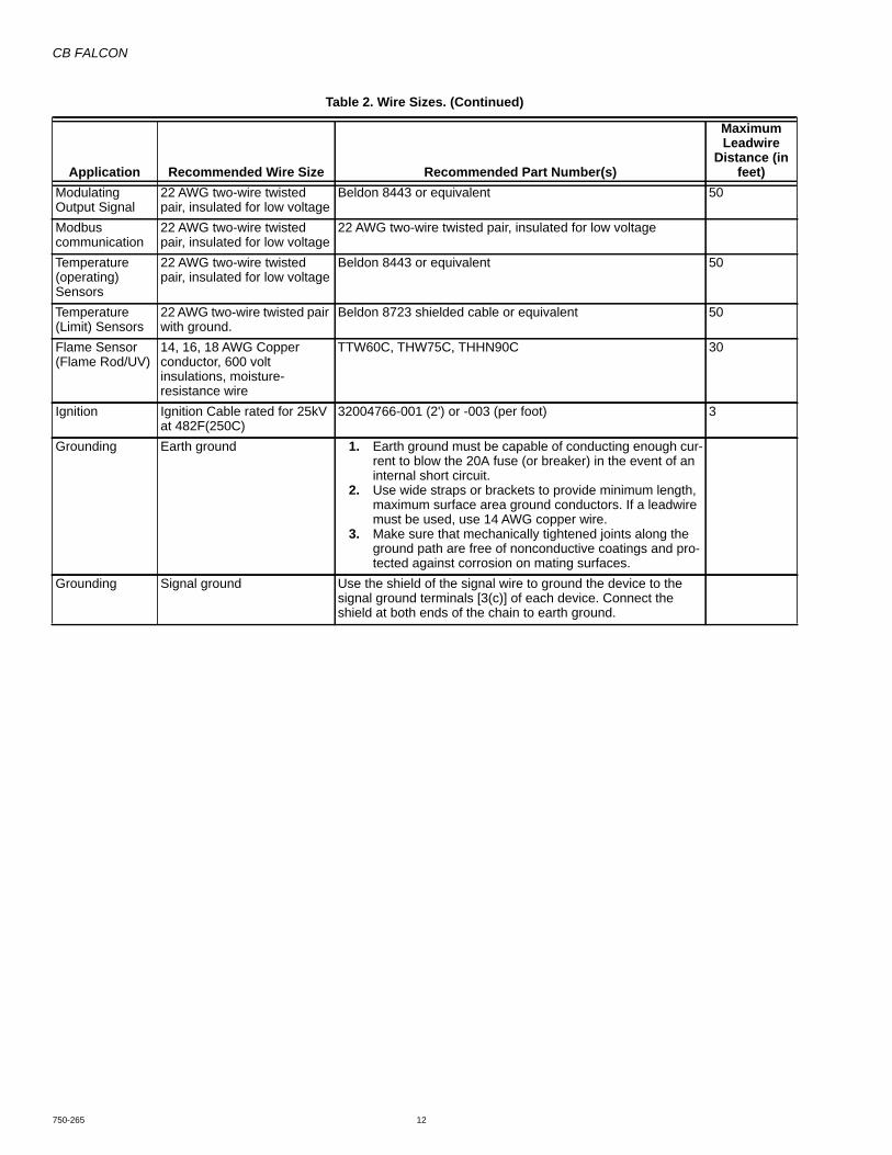
CB FALCON
750-265 12
Modulating Output Signal
22 AWG two-wire twisted pair, insulated for low voltage
Beldon 8443 or equivalent 50
Modbus communication
22 AWG two-wire twisted pair, insulated for low voltage
22 AWG two-wire twisted pair, insulated for low voltage
Temperature (operating) Sensors
22 AWG two-wire twisted pair, insulated for low voltage
Beldon 8443 or equivalent 50
Temperature (Limit) Sensors
22 AWG two-wire twisted pair with ground.
Beldon 8723 shielded cable or equivalent 50
Flame Sensor (Flame Rod/UV)
14, 16, 18 AWG Copper conductor, 600 volt insulations, moisture-resistance wire
TTW60C, THW75C, THHN90C 30
Ignition Ignition Cable rated for 25kV at 482F(250C)
32004766-001 (2') or -003 (per foot) 3
Grounding Earth ground 1. Earth ground must be capable of conducting enough cur-rent to blow the 20A fuse (or breaker) in the event of an internal short circuit.
2. Use wide straps or brackets to provide minimum length, maximum surface area ground conductors. If a leadwire must be used, use 14 AWG copper wire.
3. Make sure that mechanically tightened joints along the ground path are free of nonconductive coatings and pro-tected against corrosion on mating surfaces.
Grounding Signal ground Use the shield of the signal wire to ground the device to the signal ground terminals [3(c)] of each device. Connect the shield at both ends of the chain to earth ground.
Table 2. Wire Sizes. (Continued)
Application Recommended Wire Size Recommended Part Number(s)
Maximum Leadwire
Distance (in feet)
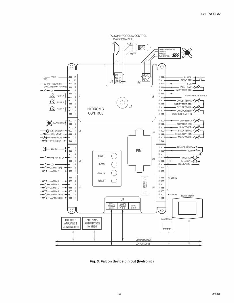
CB FALCON
13 750-265
Fig. 3. Falcon device pin out (hydronic)
3
1
4
2
FLAMESTRENGTH
LOCALMODBUSA B C
GLOBALMODBUSA B C
POWER
FLAME
ALARM
RESET
PIM
1
2
3
4
5
6
HYDRONICCONTROL
J1 J2
J3ECOMD R C
L1
L2 FOR 120VAC OR 24VAC RETURN (OPTOS)
EGND
BLOWER/HSI
EX. IGNITION
ALARM
MAIN VALVEPILOT VALVE
ANNUN 1/IASANNUN 2
ANNUN 3ANNUN 4ANNUN 5ANNUN 6
PRE IGN INTLK
INTERLOCK
P
P
P
LCI
PUMP A
{{
{
{
PUMP B
PUMP C
ANNUN 7 HFSANNUN 8 LFS
24 VAC24 VAC RTN
INLET TEMPINLET TEMP RTN
4-20 mA REMOTE SOURCE
OUTLET TEMP AOUTLET TEMP RTN
OUTLET TEMP BOUTDOOR TEMP
OUTDOOR TEMP RTN
DHW TEMP ADHW TEMP RTN
DHW TEMP BSTACK TEMP A
STACK TEMP RTNSTACK TEMP B
TODREMOTE RESET
0 - 10 VDC MA /VDC RTN
4 TO 20 MAV
I
BUILDINGAUTOMATION
SYSTEM
FUTURE System Display
TACHOMETERPWM OUT
FAN POWER (25 VDC)FAN GND
MULTIPLEAPPLIANCE
CONTROLLER
GLOBALMODBUSLOCALMODBUS
++–
FUTURE
UVBLUE
WHITE
STAT
FALCON HYDRONIC CONTROLPLUG CONNECTORS
J4
J5
J6
J7
J8
J9
J10
J11
121110 9 8 7 6 5 4 3 2 1
7654321
87654321
7654321
123456789
101112
1234567
12345678
1234567
+_
Local Display
E1
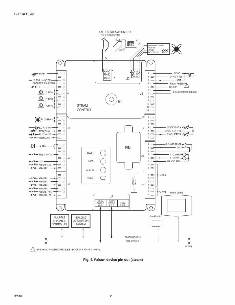
CB FALCON
750-265 14
Fig. 4. Falcon device pin out (steam)
3
1
4
2
FLAMESTRENGTH
LOCALMODBUSA B C
GLOBALMODBUSA B C
POWER
FLAME
ALARM
RESET
PIM
1
2
3
4
5
6
STEAMCONTROL
J1 J2
J3ECOMD R C
L1
L2 FOR 120VAC OR 24VAC RETURN (OPTOS)
EGND
BLOWER/HSI
EX. IGNITION
ALARM
MAIN VALVEPILOT VALVE
ANNUN 1/IASANNUN 2
ANNUN 3ANNUN 4ANNUN 5ANNUN 6
PRE IGN INTLK
INTERLOCK
P
P
P
LCI
PUMP A
{{
{
{
PUMP B
PUMP C
ANNUN 7 HFSANNUN 8 LFS
24 VAC24 VAC RTNS
STEAM PRESSURESENSOR
4-20 mA REMOTE SOURCE
STACK TEMP ASTACK TEMP RTN
STACK TEMP B
TODREMOTE RESET
0 - 10 VDC MA /VDC RTN
4 TO 20 MAV
I
BUILDINGAUTOMATION
SYSTEM
FUTURE System Display
TACHOMETERPWM OUT
FAN POWER (25 VDC)FAN GND
MULTIPLEAPPLIANCE
CONTROLLER
GLOBALMODBUSLOCALMODBUS
++–
FUTURE
UVBLUE
WHITE
STAT+–+–
EXTERNALLY POWERED PRESSURE SENSOR (0-15 PSI OR 0-150 PSI).1
1
FALCON STEAM CONTROLPLUG CONNECTORS
J4
J5
J6
J7
J8
J9
J10
J11
121110 9 8 7 6 5 4 3 2 1
7654321
87654321
7654321
123456789
101112
1234567
12345678
1234567
M27610
Local Display
E1

CB FALCON
15 750-265
Table 3. Falcon Contact.
Connector Term. Function Description and Rating (All Models)J1 1
2 FLAME ROD INPUT3 FLAME ROD COMMON4 UV56 UV COMMON
J2 1 TACH Tachometer Input (Tach) Tachometer input.2 25V Electronic Blower Motor Power (25 VDC)3 PWM Digital modulation (PWM) Output Digital modulation signal out.4 GND Ground pin for Fan interface and power
J3 a a Modbus MB1 RS-485 +b b Modbus MB1 RS-485 -c c Modbus MB1 Ground (G)a a Modbus MB2 RS-485 +b b Modbus MB2 RS-485 -c c Modbus MB2 RS-485 Ground (G)1 1 ECOM Data (1)2 2 ECOM Receive (2)3 3 ECOM (3)
J4 12 EARTH GROUND Earth groundNot Used Not UsedJ4 10 L2 Power Supply NeutralNot Used Not UsedJ4 8 L1 120 VAC (+ 10/15%, 50 or 60 HZ) to power UVJ4 7 PUMP A Input 120 VAC: 44.4 ALR, 7.4 Amps runJ4 6 PUMP A Output 120 VAC: 44.4 ALR, 7.4 Amps runJ4 5 PUMP B Input 120 VAC: 44.4 ALR, 7.4 Amps runJ4 4 PUMP B Output 120 VAC: 44.4 ALR, 7.4 Amps runJ4 3 PUMP C Input 120 VAC: 44.4 ALR, 7.4 Amps runJ4 2 PUMP C Output 120 VAC: 44.4 ALR, 7.4 Amps runJ4 1 Not UsedJ5 7 BLOWER/HSI Input 24VAC, 120 VAC: 44.4 ALR, 7.4 Amps runJ5 6 BLOWER/HSI Output 24VAC, 120 VAC: 44.4 ALR, 7.4 Amps runJ5 5 Not UsedJ5 4 EXT. IGNITION See Table 6J5 3 MAIN VALVE See Table 6J5 2 PILOT VALVE See Table 6J5 1 INTERLOCK Per Model Input Rating
J6 8 ALARM Input 24VAC, 120 VAC: 6.3 ALR, 0.63 Amps full loadJ6 7 ALARM Output 24VAC, 120 VAC: 6.3 ALR, 0.63 Amps full loadJ6 6 Not UsedJ6 5 Pre-Ignition Interlock (PII) 24VAC, 120 VAC: 2 mA maximumJ6 4 Not UsedJ6 3 Load/Limit Control Input (LCI) 24VAC, 120 VAC: 2 mA maximumJ6 2 Annunc1 / IAS 24VAC, 120 VAC: 2 mA maximum
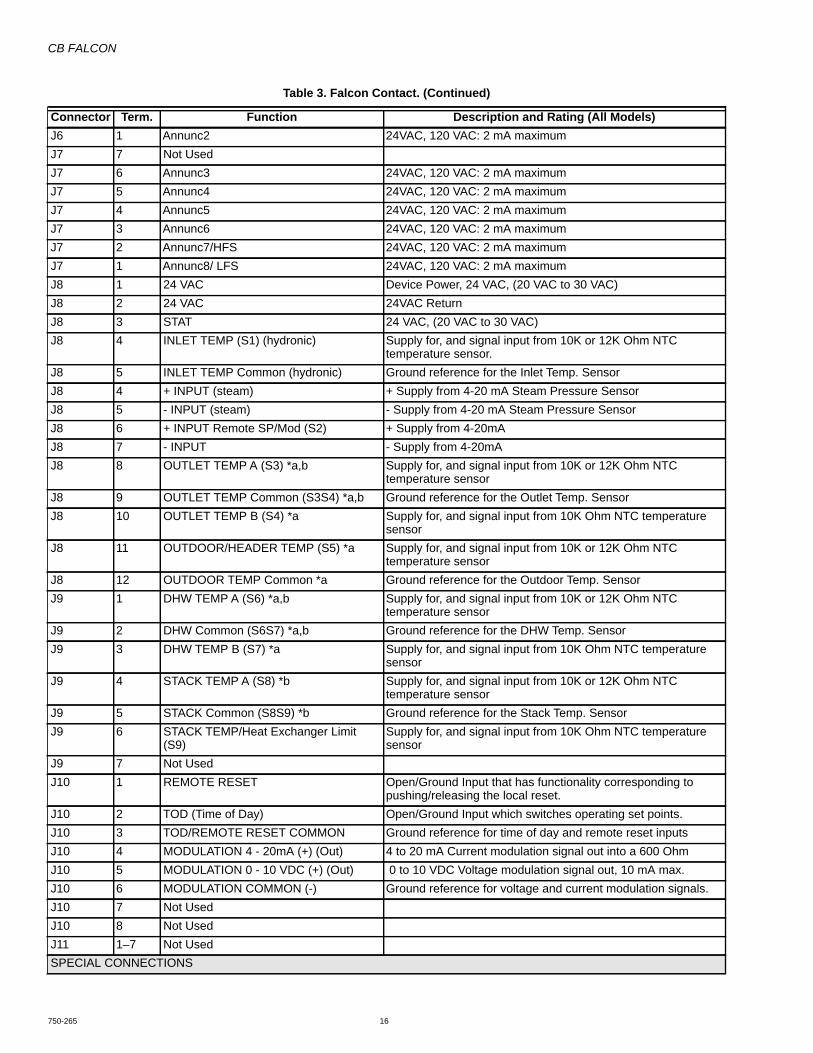
CB FALCON
750-265 16
J6 1 Annunc2 24VAC, 120 VAC: 2 mA maximumJ7 7 Not UsedJ7 6 Annunc3 24VAC, 120 VAC: 2 mA maximumJ7 5 Annunc4 24VAC, 120 VAC: 2 mA maximumJ7 4 Annunc5 24VAC, 120 VAC: 2 mA maximumJ7 3 Annunc6 24VAC, 120 VAC: 2 mA maximumJ7 2 Annunc7/HFS 24VAC, 120 VAC: 2 mA maximumJ7 1 Annunc8/ LFS 24VAC, 120 VAC: 2 mA maximumJ8 1 24 VAC Device Power, 24 VAC, (20 VAC to 30 VAC)J8 2 24 VAC 24VAC ReturnJ8 3 STAT 24 VAC, (20 VAC to 30 VAC)J8 4 INLET TEMP (S1) (hydronic) Supply for, and signal input from 10K or 12K Ohm NTC
temperature sensor.J8 5 INLET TEMP Common (hydronic) Ground reference for the Inlet Temp. SensorJ8 4 + INPUT (steam) + Supply from 4-20 mA Steam Pressure SensorJ8 5 - INPUT (steam) - Supply from 4-20 mA Steam Pressure SensorJ8 6 + INPUT Remote SP/Mod (S2) + Supply from 4-20mAJ8 7 - INPUT - Supply from 4-20mAJ8 8 OUTLET TEMP A (S3) *a,b Supply for, and signal input from 10K or 12K Ohm NTC
temperature sensorJ8 9 OUTLET TEMP Common (S3S4) *a,b Ground reference for the Outlet Temp. SensorJ8 10 OUTLET TEMP B (S4) *a Supply for, and signal input from 10K Ohm NTC temperature
sensorJ8 11 OUTDOOR/HEADER TEMP (S5) *a Supply for, and signal input from 10K or 12K Ohm NTC
temperature sensorJ8 12 OUTDOOR TEMP Common *a Ground reference for the Outdoor Temp. SensorJ9 1 DHW TEMP A (S6) *a,b Supply for, and signal input from 10K or 12K Ohm NTC
temperature sensorJ9 2 DHW Common (S6S7) *a,b Ground reference for the DHW Temp. SensorJ9 3 DHW TEMP B (S7) *a Supply for, and signal input from 10K Ohm NTC temperature
sensorJ9 4 STACK TEMP A (S8) *b Supply for, and signal input from 10K or 12K Ohm NTC
temperature sensorJ9 5 STACK Common (S8S9) *b Ground reference for the Stack Temp. SensorJ9 6 STACK TEMP/Heat Exchanger Limit
(S9)Supply for, and signal input from 10K Ohm NTC temperature sensor
J9 7 Not UsedJ10 1 REMOTE RESET Open/Ground Input that has functionality corresponding to
pushing/releasing the local reset.J10 2 TOD (Time of Day) Open/Ground Input which switches operating set points.J10 3 TOD/REMOTE RESET COMMON Ground reference for time of day and remote reset inputsJ10 4 MODULATION 4 - 20mA (+) (Out) 4 to 20 mA Current modulation signal out into a 600 OhmJ10 5 MODULATION 0 - 10 VDC (+) (Out) 0 to 10 VDC Voltage modulation signal out, 10 mA max.J10 6 MODULATION COMMON (-) Ground reference for voltage and current modulation signals.J10 7 Not UsedJ10 8 Not UsedJ11 1–7 Not UsedSPECIAL CONNECTIONS
Table 3. Falcon Contact. (Continued)
Connector Term. Function Description and Rating (All Models)
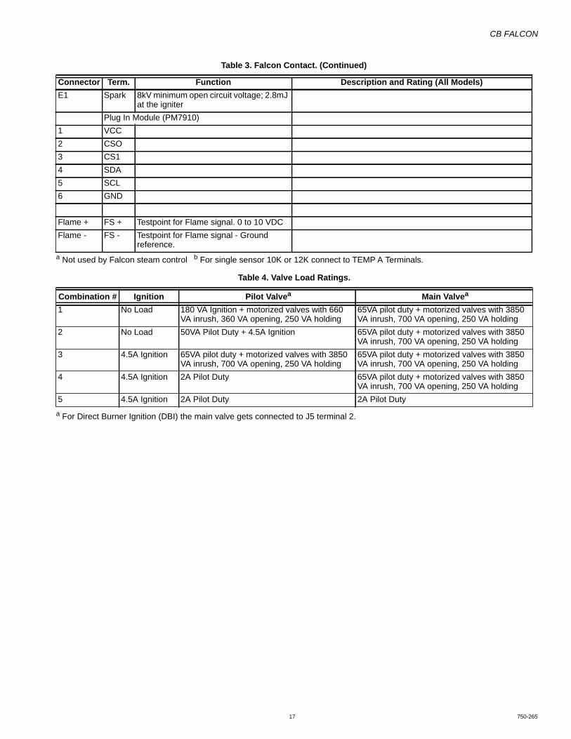
CB FALCON
17 750-265
a Not used by Falcon steam control b For single sensor 10K or 12K connect to TEMP A Terminals.
a For Direct Burner Ignition (DBI) the main valve gets connected to J5 terminal 2.
E1 Spark 8kV minimum open circuit voltage; 2.8mJ at the igniter
Plug In Module (PM7910)1 VCC2 CSO3 CS14 SDA5 SCL6 GND
Flame + FS + Testpoint for Flame signal. 0 to 10 VDCFlame - FS - Testpoint for Flame signal - Ground
reference.
Table 4. Valve Load Ratings.
Combination # Ignition Pilot Valvea Main Valvea
1 No Load 180 VA Ignition + motorized valves with 660 VA inrush, 360 VA opening, 250 VA holding
65VA pilot duty + motorized valves with 3850 VA inrush, 700 VA opening, 250 VA holding
2 No Load 50VA Pilot Duty + 4.5A Ignition 65VA pilot duty + motorized valves with 3850 VA inrush, 700 VA opening, 250 VA holding
3 4.5A Ignition 65VA pilot duty + motorized valves with 3850 VA inrush, 700 VA opening, 250 VA holding
65VA pilot duty + motorized valves with 3850 VA inrush, 700 VA opening, 250 VA holding
4 4.5A Ignition 2A Pilot Duty 65VA pilot duty + motorized valves with 3850 VA inrush, 700 VA opening, 250 VA holding
5 4.5A Ignition 2A Pilot Duty 2A Pilot Duty
Table 3. Falcon Contact. (Continued)
Connector Term. Function Description and Rating (All Models)

CB FALCON
750-265 18
STARTUPThe Falcon is shipped in the unconfigured condition, so when power is applied, all safety loads are off and the burner status when viewed from the display is shown as “Safety data setup needed.”
Once the Safety Data is configured, the Falcon is ready to operate a boiler.
Commissioning
PasswordsA password level of protection may be assigned to any parameter. Three levels are shown in decreasing order of privilege:
1. OEM password required—allows access to all parame-ters
2. Installer password required—allows access to some parameters
3. End User (no password)—allows access to non-pass-word parameters
Whenever a valid password has been provided, the Falcon remains in the access level of that password until either 10 minutes of inactivity (no more edits) has occurred or the command is received to exit to the normal no-password state.
The OEM and Installer passwords are given a default value when the Falcon is shipped, but may be changed later using the Configuration program, the system display, or the electronic configuration tool.
Parameter Control Blocks (PCB)The Falcon Parameters are managed using control blocks. There are three parameter control blocks (PCB) that may be installed into the memory of the Falcon:
1. OEM Parameter PCB—makes any parameter hidden and/or unalterable and assigns the password level
2. OEM Alert PCB—determines which alerts are enabled and, for those that are enabled, if the alert causes the alarm contacts to close.
3. OEM Range PCB—limits the range of any parameter.
A parameter control block can be downloaded using a file-transfer method that operates within the Modbus protocol. The Falcon Modbus defines the format of parameter control block data and the download procedure. All of the OEM PCBs require the OEM password before they can be downloaded.
The Software Configuration Tool allows all available parameters to be viewed, modified, and downloaded. This tool allows for building a device working from a spreadsheet. Customizing can be done on this, along with choosing to have the parameter Hidden, Read Only, or Level of Password protection. When complete this sheet can be saved and/or directly downloaded into the Falcon through the Modbus port. An example is shown in Table 49, beginning on page 100.
OEM PARAMETER PCB:Providing the OEM password allows downloading of a parameter control block for OEM protected data. This block assigns the value of these attributes for each parameter:• Range Limit—If provided the parameter's value will be
limited.• Hidden—This attribute prevents the parameter from
showing in the display - it is hidden.• Read-only—This attribute prevents the parameter from
being changed.• Password—The password attribute defines the level of
password needed to alter the item: OEM, Installer, or none.
The interaction and behavior of these settings is shown in Table 6. (All parameters are readable via Modbus, however a Modbus error response message is sent if an attempt is made to write one that is marked read-only, or that requires a password and the appropriate password level is not in-effect.)
OEM ALERT PCBProviding the OEM password allows downloading of a parameter control block for alerts.
• Each item in this block enables/disables the alert - a disabled alert is never shown.
• An enabled alert has the option of closing the alarm contacts, whenever this alert occurs.
OEM RANGE PCBProviding the OEM password allows downloading of a parameter control block for range limits.
• This block specifies the minimum and maximum values for any writable parameter that accepts a numeric range, and for parameters that are enumerated lists, it can suppress
Table 5. Interaction of OEM Parameter Settings.
Hidden Read-only PasswordSystem Display Modbus register I/O
Shown Write Read Write0 0 0 Yes Anytime Yes Yes0 0 1 Yes Need Password Yes Need Password0 1 x Yes No Yes No1 0 0 No No Yes Yes1 0 1 No No Yes Need Password1 1 x No No Yes No
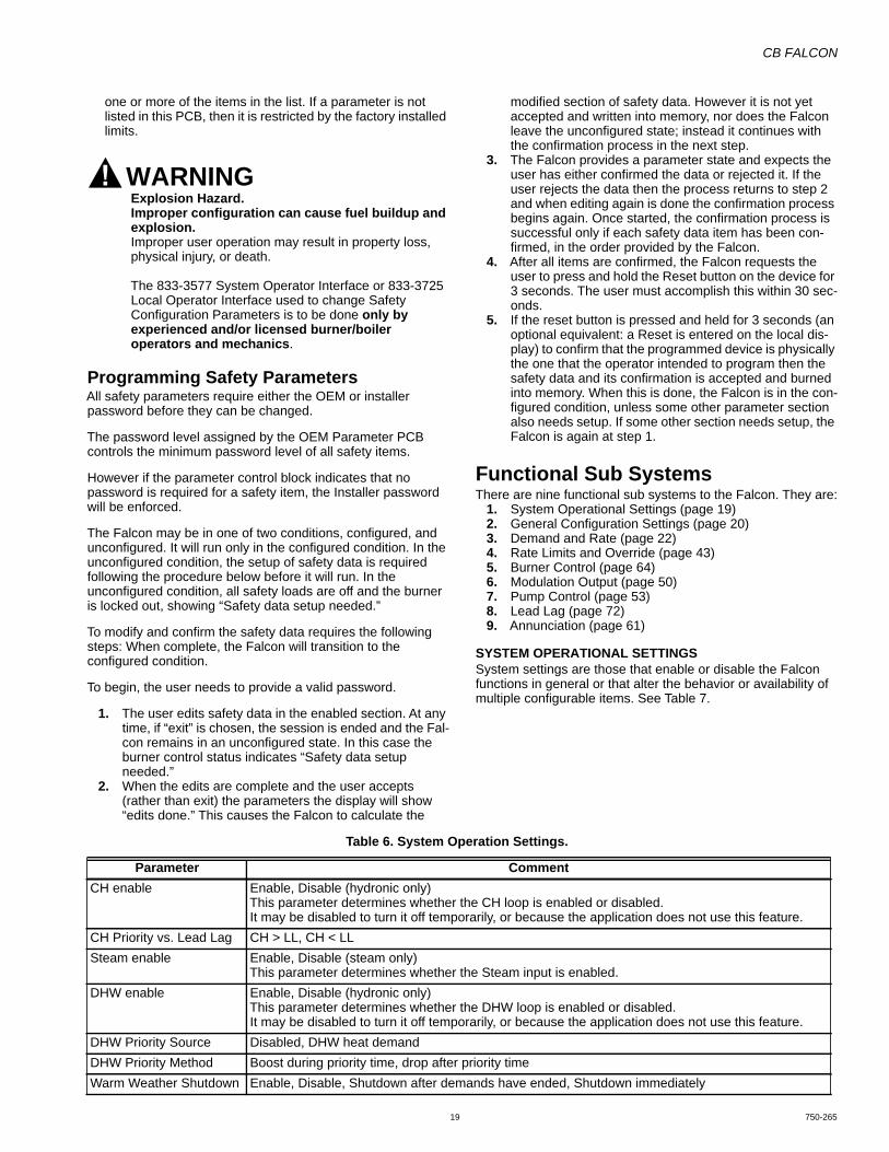
CB FALCON
19 750-265
one or more of the items in the list. If a parameter is not listed in this PCB, then it is restricted by the factory installed limits.
WARNINGExplosion Hazard.Improper configuration can cause fuel buildup and explosion.Improper user operation may result in property loss, physical injury, or death.
The 833-3577 System Operator Interface or 833-3725 Local Operator Interface used to change Safety Configuration Parameters is to be done only by experienced and/or licensed burner/boiler operators and mechanics.
Programming Safety ParametersAll safety parameters require either the OEM or installer password before they can be changed.
The password level assigned by the OEM Parameter PCB controls the minimum password level of all safety items.
However if the parameter control block indicates that no password is required for a safety item, the Installer password will be enforced.
The Falcon may be in one of two conditions, configured, and unconfigured. It will run only in the configured condition. In the unconfigured condition, the setup of safety data is required following the procedure below before it will run. In the unconfigured condition, all safety loads are off and the burner is locked out, showing “Safety data setup needed.”
To modify and confirm the safety data requires the following steps: When complete, the Falcon will transition to the configured condition.
To begin, the user needs to provide a valid password.
1. The user edits safety data in the enabled section. At any time, if “exit” is chosen, the session is ended and the Fal-con remains in an unconfigured state. In this case the burner control status indicates “Safety data setup needed.”
2. When the edits are complete and the user accepts (rather than exit) the parameters the display will show “edits done.” This causes the Falcon to calculate the
modified section of safety data. However it is not yet accepted and written into memory, nor does the Falcon leave the unconfigured state; instead it continues with the confirmation process in the next step.
3. The Falcon provides a parameter state and expects the user has either confirmed the data or rejected it. If the user rejects the data then the process returns to step 2 and when editing again is done the confirmation process begins again. Once started, the confirmation process is successful only if each safety data item has been con-firmed, in the order provided by the Falcon.
4. After all items are confirmed, the Falcon requests the user to press and hold the Reset button on the device for 3 seconds. The user must accomplish this within 30 sec-onds.
5. If the reset button is pressed and held for 3 seconds (an optional equivalent: a Reset is entered on the local dis-play) to confirm that the programmed device is physically the one that the operator intended to program then the safety data and its confirmation is accepted and burned into memory. When this is done, the Falcon is in the con-figured condition, unless some other parameter section also needs setup. If some other section needs setup, the Falcon is again at step 1.
Functional Sub SystemsThere are nine functional sub systems to the Falcon. They are:
1. System Operational Settings (page 19)2. General Configuration Settings (page 20)3. Demand and Rate (page 22)4. Rate Limits and Override (page 43)5. Burner Control (page 64)6. Modulation Output (page 50)7. Pump Control (page 53)8. Lead Lag (page 72)9. Annunciation (page 61)
SYSTEM OPERATIONAL SETTINGSSystem settings are those that enable or disable the Falcon functions in general or that alter the behavior or availability of multiple configurable items. See Table 7.
Table 6. System Operation Settings.
Parameter CommentCH enable Enable, Disable (hydronic only)
This parameter determines whether the CH loop is enabled or disabled.It may be disabled to turn it off temporarily, or because the application does not use this feature.
CH Priority vs. Lead Lag CH > LL, CH < LLSteam enable Enable, Disable (steam only)
This parameter determines whether the Steam input is enabled. DHW enable Enable, Disable (hydronic only)
This parameter determines whether the DHW loop is enabled or disabled.It may be disabled to turn it off temporarily, or because the application does not use this feature.
DHW Priority Source Disabled, DHW heat demandDHW Priority Method Boost during priority time, drop after priority timeWarm Weather Shutdown Enable, Disable, Shutdown after demands have ended, Shutdown immediately

CB FALCON
750-265 20
GENERAL CONFIGURATION SETTINGSThose that alter the behavior or availability of configurable
items that are not in any other category. Those that are not defined in other sections are listed in Table 8:
Warm Weather Shutdown Setpoint
Temperature, None
Lead Lag slave enable Enable, Disable (hydronic only)Lead Lag Master enable Enable, Disable (hydronic only)DHW priority vs LLDHW priority vs CH
These parameters determine the priority of DHW versus other sources of calls-for-heat, when more than one source is enabled. The LL source has a fixed priority versus the CH source: if an Falcon is set up as a LL slave, and a LL master is controlling it, then the CH source is ignored.
DHW priority override time mm:ssThis parameter determines whether a DHW demand can temporarily override the priority defined by the DHW priority parameters. If it is non zero, then a DHW demand will take priority over both the LL demand and the CH demand, for the specified time. If the DHW demand persists for longer than the specified time then this override priority will expire and control will revert to the normal priority. The override timer is reset when demand from the DHW source turns off. If normal DHW priority is already higher than the one or both of the competing priorities, then this parameter has no effect versus the competing priority.
Annunciation enable(Model Specific)
Enable, DisableThis parameter determines whether the Annunciator feature of the Falcon are active. When disabled, the Falcon will ignore the Annunciator inputs.It may be disabled to turn it off temporarily, but more typically this will be turned off because the application does not use this feature.
Burner Switch On, OffThis parameter enables or disables the burner control. When it is off, the burner will not fire.
Inlet Connector Type For Falcon Hydronic Control10K NTC single non-safety12K NTC single non-safetyUNCONFIGURED
For Steam Control15 PSI, 150 PSI, or UNCONFIGURED
Designates the type of analog sensor on connector J8 terminals 4 and 5.Outlet Connector Type For Falcon Hydronic Control and Steam Control
10K NTC dual safety-connector J8 terminals 8, 9, and 1010K or 12K NTC single non-safety-connector J8 terminals 8 and 9Designates the type of analog sensor used. NOTE: the 10K NTC is a dual sensor used for safety limits and requires safety verification during setup.
DHW Connector Type For Falcon Hydronic Control and Steam Control10K NTC dual safety-connector J9 terminals 1, 2, and 310K or 12K NTC single non-safety-connector J9 terminals 1 and 2Designates the type of analog sensor type used. NOTE: the 10K NTC is a dual sensor used for safety limits and requires safety verification during setup.
Stack Connector Type For Falcon Hydronic Control and Steam Control 10K NTC dual safety-connector J9 terminals 4, 5 and 610K or 12K NTC single non-safety-connector J9 terminals 4 and 5Designates the type of analog sensor type used. NOTE: the 10K NTC is a dual sensor used for safety limits and requires safety verification during setup.
Outdoor Connector Type For Falcon Hydronic Control10K NTC single non-safety12K NTC single non-safetyFor Steam Control - there is not an Outdoor Sensor Feature. Designates the type of analog sensor type is on connector J8 terminals 11 and 12.
DHW Priority Time ODR Enable
Disable, EnableWhen enabled, the DHW priority override time parameter will be derated when the outdoor temperature is below 32°F. When the outdoor temperature is 32°F and above, the programmed time will be used as-is. When the outdoor temperature is -40°F and below, the programmed override time will be derated to zero (no override). Between 32°F and -40°F, a linear interpolation will be used. For example, at the midway point of -4°F, the DHW priority override time is one half of the value provided by the parameter.
Table 6. System Operation Settings. (Continued)
Parameter Comment

CB FALCON
21 750-265
Table 7. General Configuration Settings.
Parameter CommentTemperature Units F, C
This parameter determines whether the temperature is represented in units of Fahrenheit or Celsius degrees.
Anti short cycle time mm:ssWhenever the burner is turned off due to no demand, the anti short cycle timer is started and the burner remains in a Standby Delay condition waiting for this time to expire. The anti short cycle time does not apply, however, to recycle events such as loss of airflow or flame, it applies only to loss of demand.The anti short cycle time always inhibits a CH or LL demand. However, if a DHW demand occurs then its priority is checked. If it has the highest priority because of either:• a non-zero value in the DHW priority timer (which is loaded using the DHW priority time
parameter)• due to the setting in both: DHW priority vs LL (if Lead Lag Master enable is enabled) AND DHW
priority vs CH (if CH enable is enabled)• then the anti short cycle delay is ignored and the DHW demand is served.
Burner name textThe Burner Name is a text parameter stored in the Falcon to identify the burner.
OEM ID textThe OEM ID is a text parameter stored in the Falcon intended for use by an OEM to record identification information related to the OEM's configuration and setup of the Falcon.
Installation Data textThe Installation Data is a text parameter stored in the Falcon. It is intended for use by the installer to record identification information about how the Falcon was set up at the installation time.

CB FALCON
750-265 22
Demand and RateThe Demand and Rate subsystem produces 3 outputs:
• Pump demand• Burner demand, which tells the burner control it should fire,
and• the modulation rate, which is the burner’s firing rate.
There are three normal sources that share use of the burner:
• Central Heating (CH) or Steam• Domestic Hot Water (DHW) hydronic only • Lead Lag (LL)
These are all similar in that:
• Their inputs are a temperature sensor (pressure for steam) and a setpoint value.
• Their outputs are:a. On/off pump demandb. An on/off demand indication that is on if the subsys-
tem wants the burner to fire.c. A modulation rate which is a percentage value
between 0% and 100% that the subsystem wants as the burners firing rate.
• They use a PID calculation to set the modulation rate.
Each of these sources has its own separate parameters.
Additionally the Falcon hydronic has two sources that can call for burner firing, but do not use a PID calculation or modulate to a setpoint: CH Frost Protection and DHW frost protection, which always fire at the minimum modulation rate.
PID Requirements as a replacement for MCBA Control:The internal gain scalers for P, I, and D can be calibrated so that the gains for a legacy MCBA control can be copied to the Falcon without conversion at one specific maximum fan speed.
The chosen fan speed for calibrating these scalers is 5000 RPM, that is, when both the MCBA and the Falcon have a maximum fan speed of 5000 RPM, the user-programmable P, I, and D gains used by the MCBA can be directly copied to the corresponding Falcon parameters, and the behavior of the Falcon control will then be similar to the MCBA.
At other values of maximum fan speed, the parameters to provide similar behavior can be calculated as:
GAINFALCON = GAINMCBA * Max_fan_speed / 5000
Demand/Rate Selection and Limiting (example using Falcon Hydronic Control)These sources of demand and modulation rate are processed by a priority selector that determines which of the sources (Central Heating [CH], Domestic Hot Water [DHW], or Lead Lag Master [LL]) actually has control of the burner.
The frost protection source has control only if none of the others want the burner to fire.
Additionally, the modulation rate requested by the source can be modified by rate limiting, which adjusts the burner firing rate during special conditions and it can be overridden by manual control or burner control (e.g. prepurge and lightoff).
The descriptions of the parameters shown in Fig. 5 occur elsewhere in this document:
• The enables and the DHW priority timeout are in “Burner Control Operation” on page 64.
• Manual Rate control is in “Modulation Output” on page 50.• Frost Protection is in “Frost Protection (Hydronic only)” on
page 40.• Various Rate Limiting inputs are in “Rate Limits and
Override” on page 43.
The Demand/Rate Selection subsystem is connected internally in the Falcon as shown in Fig. 5:
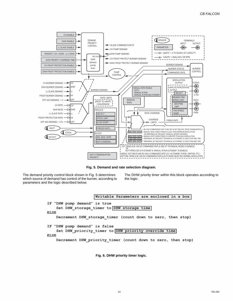
CB FALCON
23 750-265
Fig. 5. Demand and rate selection diagram.
The demand priority control block shown in Fig. 5 determines which source of demand has control of the burner, according to parameters and the logic described below.
The DHW priority timer within this block operates according to the logic:
Fig. 6. DHW priority timer logic.
ANTI-CONDENS...
BOOST:
“mRATE” = ANALOG% OR RPM
PARAMETER
SENSOR
“pRATE” = 0 TO 99.99% OF CAPACITY
INPUT OUTPUTTERMINALS
DELTA-T ...
STACK LIMIT ...
SLOW START ...
REDUCE:
ANTI-CONDENSATION PRIORITY
STACK
CH BURNER DEMAND
DHW BURNER DEMAND
LL SLAVE DEMAND BURNER DEMAND
BURNER DEMAND
BURNER STATUSCOMMANDED RATE
ANALOG PERCENTAGE OUTPUT
MIN/MAX FANSPEED LIMIT
MIN PWMLIMIT
MIN. MOD. RATE
MAX. MOD. RATEABS. MIN. RATE
ABS. MAX. RATE
FAN SPEEDRAMP
CH RATE
DHW RATELL SLAVE RATE
RATE LIMITS
RATE OVERRIDE
OVERRIDELIMITS
FIRING RATE
PWM
4-20mA
0-10V
INLET
OUTLET
FROST BURNER DEMAND
FROST PROTECTION RATE
DEMANDPRIORITYCONTROL
DHW ENABLE
CH ENABLE
PRIORITY: CH <>DWH LL<>DHW
pRATE TO mRATECONVERSION
TOP: FIRING & BC HAS NO COMMANDED RATE & ONE OF THE MANUAL MODES IS ENABLED. OR
NOT FIRING & BC IS IN STANDBY & “MANUAL IN RUN & STANDBY” IS ENABLED. MIDDLE: NOT ABOVE AND BC HAS A COMMANDED RATE (E.G. IN STANDBY, PURGE, IDNITION, ETC.) BOTTOM: FIRING & BC HAS NO COMMANDED RATE & AUTO MODE SELECTED (NORMAL MODULATION)
OFF (NO DEMAND) = 0
OFF (NO DEMAND) = 0%
DHWdemandprioritytimer
CH PUMP DEMAND
DHW PUMP DEMAND
SLAVE COMMAND EXISTS
CH FROST PROTECT BURNER DEMAND
LL SLAVE ENABLE
DHW FROST PROTECT BURNER DEMAND
DHW FROST PROTECTION ENABLE
RELOAD
CHDHW
LL
FP
OFF
CH
DHW
LL
FPOFF
0 = BC HAS COMMANDED FAN TO BE OFF & NOT BELOW; OR BC DISABLED/FAULT. = MANUAL RATE WHEN FIRING IS LESS THAN MINIMUM MODULATION,
OR ABNORMAL BC REQUEST (MANUAL MODES IGNORED).= MANUAL RATE WHEN FIRING IS GREATER THAN MAX MODULATION. = ABNORMAL BC REQUEST OR MANUAL IN STANDBY IS LESS THAN ABS. MIN.= ABNORMAL BC REQUEST OR MANUAL IN STANDBY IS LESS THAN ABS. MIN.
TACH
PUMPCONTROL
BURNERCONTROL
MODULATIONOUTPUT
MIN. MOD. RATE
FORCED RATE...
DHW PRIORITY OVERRIDE TIME
CH FROST PROTECTION ENABLE
MANUAL RATE ENABLE- AUTO- MANUAL IN RUN- MANUAL IN RUN AND STANDBY
MANUALRATE
SELECT
IF “DHW pump demand” is true Set DHW_storage_timer to DHW storage timeELSE Decrement DHW_storage_timer (count down to zero, then stop)IF “DHW pump demand” is false Set DHW_priority_timer to DHW priority override timeELSE Decrement DHW_priority_timer (count down to zero, then stop)
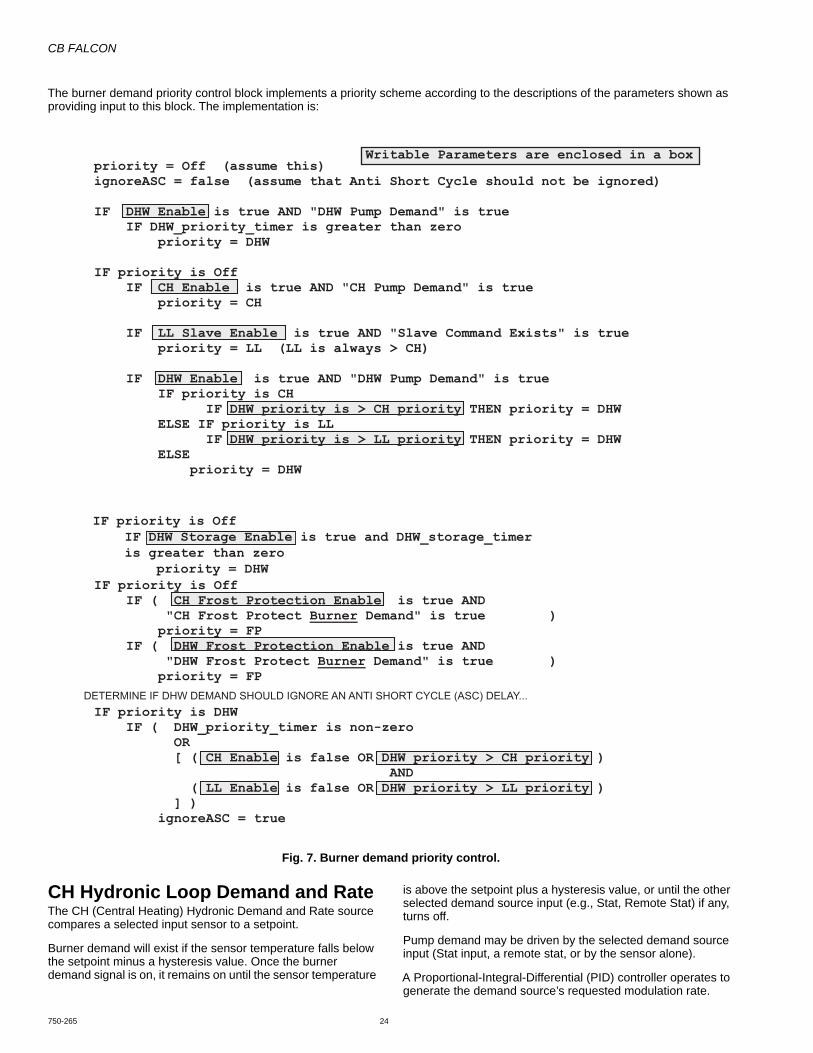
CB FALCON
750-265 24
The burner demand priority control block implements a priority scheme according to the descriptions of the parameters shown as providing input to this block. The implementation is:
Fig. 7. Burner demand priority control.
CH Hydronic Loop Demand and RateThe CH (Central Heating) Hydronic Demand and Rate source compares a selected input sensor to a setpoint.
Burner demand will exist if the sensor temperature falls below the setpoint minus a hysteresis value. Once the burner demand signal is on, it remains on until the sensor temperature
is above the setpoint plus a hysteresis value, or until the other selected demand source input (e.g., Stat, Remote Stat) if any, turns off.
Pump demand may be driven by the selected demand source input (Stat input, a remote stat, or by the sensor alone).
A Proportional-Integral-Differential (PID) controller operates to generate the demand source’s requested modulation rate.
DETERMINE IF DHW DEMAND SHOULD IGNORE AN ANTI SHORT CYCLE (ASC) DELAY...
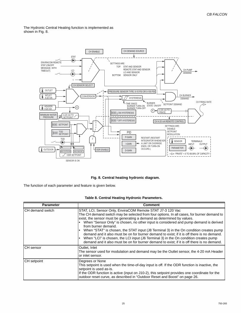
CB FALCON
25 750-265
The Hydronic Central Heating function is implemented as shown in Fig. 8.
Fig. 8. Central heating hydronic diagram.
The function of each parameter and feature is given below.
P-GAIN
I-GAIN
D-GAIN
PIDTOD SETPOINT
SETPOINT
ON HYSTERESIS
OFF HYSTERESIS
OUTLET
CH BURNERDEMAND
CH FIRING RATEHYSTERESIS
TOD
HEADER4-20 mA
STAT
ENVIRACOM REMOTE STAT (ON/OFF MESSAGE, WITH TIMEOUT)
CH DEMAND SOURCE
TIME SINCE: BURNER TURN-ON BURNER TURN-OFF
BURNERSTATE: ON/OFF
SETTINGS ARE:TOP: STAT AND SENSOR
REMOTE STAT AND SENSORLCI AND SENSOR SENSOR ONLYBOTTOM:
CH PUMPDEMAND
1
SETPOINT DEMAND
PARAMETER
“PRATE” = 0 TO 99.99% OF CAPACITY
INPUT OUTPUTTERMINALS
CH ENABLE
RESTART (RESTART INTEGRATOR WHENEVERA LIMIT OR OVERRIDE ENDS, OR TURN-ON OCCURS.)
LCI
CH SENSOR SELECT
INTLET4-20 mA CONVERSION
A
4-20 mA TOSETPOINT
MINIMUM WATERPRESSURE
PRESSURE SENSOR TYPE: 0-15 PSI OR 0-150 PSI
4-20 mA TOPRATE
A
CH 4-20 mA REMOTE CONTROL
SETTINGS ARE: DISABLE SETPOINT MODULATION
OUTDOORMAX OUTDOOR MAX INDOOR
ODR SETPOINT
ODR ENABLE
SENSOR
SENSOR IS OK
Table 8. Central Heating Hydronic Parameters.
Parameter CommentCH demand switch STAT, LCI, Sensor Only, EnviraCOM Remote STAT J7-3 120 Vac
The CH demand switch may be selected from four options. In all cases, for burner demand to exist, the sensor must be generating a demand as determined by values.• When “Sensor Only” is chosen, no other input is considered and pump demand is derived
from burner demand.• When “STAT” is chosen, the STAT input (J8 Terminal 3) in the On condition creates pump
demand and it also must be on for burner demand to exist; if it is off there is no demand.• When “LCI” is chosen, the LCI input (J6 Terminal 3) in the On condition creates pump
demand and it also must be on for burner demand to exist; if it is off there is no demand.CH sensor Outlet, Inlet
The sensor used for modulation and demand may be the Outlet sensor, the 4-20 mA Header or inlet sensor.
CH setpoint Degrees or NoneThis setpoint is used when the time-of-day input is off. If the ODR function is inactive, the setpoint is used as-is.If the ODR function is active (input on J10-2), this setpoint provides one coordinate for the outdoor reset curve, as described in “Outdoor Reset and Boost” on page 26.
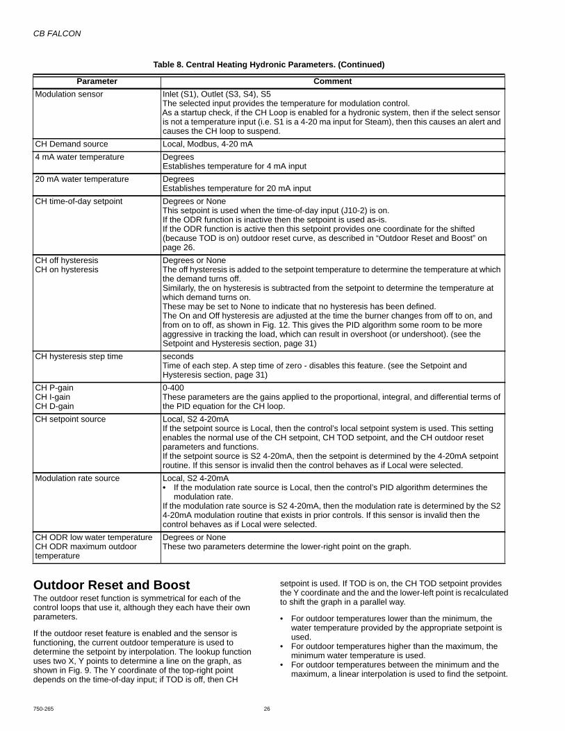
CB FALCON
750-265 26
Outdoor Reset and BoostThe outdoor reset function is symmetrical for each of the control loops that use it, although they each have their own parameters.
If the outdoor reset feature is enabled and the sensor is functioning, the current outdoor temperature is used to determine the setpoint by interpolation. The lookup function uses two X, Y points to determine a line on the graph, as shown in Fig. 9. The Y coordinate of the top-right point depends on the time-of-day input; if TOD is off, then CH
setpoint is used. If TOD is on, the CH TOD setpoint provides the Y coordinate and the and the lower-left point is recalculated to shift the graph in a parallel way.
• For outdoor temperatures lower than the minimum, the water temperature provided by the appropriate setpoint is used.
• For outdoor temperatures higher than the maximum, the minimum water temperature is used.
• For outdoor temperatures between the minimum and the maximum, a linear interpolation is used to find the setpoint.
Modulation sensor Inlet (S1), Outlet (S3, S4), S5The selected input provides the temperature for modulation control.As a startup check, if the CH Loop is enabled for a hydronic system, then if the select sensor is not a temperature input (i.e. S1 is a 4-20 ma input for Steam), then this causes an alert and causes the CH loop to suspend.
CH Demand source Local, Modbus, 4-20 mA4 mA water temperature Degrees
Establishes temperature for 4 mA input20 mA water temperature Degrees
Establishes temperature for 20 mA inputCH time-of-day setpoint Degrees or None
This setpoint is used when the time-of-day input (J10-2) is on.If the ODR function is inactive then the setpoint is used as-is.If the ODR function is active then this setpoint provides one coordinate for the shifted (because TOD is on) outdoor reset curve, as described in “Outdoor Reset and Boost” on page 26.
CH off hysteresisCH on hysteresis
Degrees or NoneThe off hysteresis is added to the setpoint temperature to determine the temperature at which the demand turns off.Similarly, the on hysteresis is subtracted from the setpoint to determine the temperature at which demand turns on. These may be set to None to indicate that no hysteresis has been defined.The On and Off hysteresis are adjusted at the time the burner changes from off to on, and from on to off, as shown in Fig. 12. This gives the PID algorithm some room to be more aggressive in tracking the load, which can result in overshoot (or undershoot). (see the Setpoint and Hysteresis section, page 31)
CH hysteresis step time secondsTime of each step. A step time of zero - disables this feature. (see the Setpoint and Hysteresis section, page 31)
CH P-gainCH I-gainCH D-gain
0-400These parameters are the gains applied to the proportional, integral, and differential terms of the PID equation for the CH loop.
CH setpoint source Local, S2 4-20mAIf the setpoint source is Local, then the control’s local setpoint system is used. This setting enables the normal use of the CH setpoint, CH TOD setpoint, and the CH outdoor reset parameters and functions.If the setpoint source is S2 4-20mA, then the setpoint is determined by the 4-20mA setpoint routine. If this sensor is invalid then the control behaves as if Local were selected.
Modulation rate source Local, S2 4-20mA• If the modulation rate source is Local, then the control’s PID algorithm determines the
modulation rate.If the modulation rate source is S2 4-20mA, then the modulation rate is determined by the S2 4-20mA modulation routine that exists in prior controls. If this sensor is invalid then the control behaves as if Local were selected.
CH ODR low water temperatureCH ODR maximum outdoor temperature
Degrees or NoneThese two parameters determine the lower-right point on the graph.
Table 8. Central Heating Hydronic Parameters. (Continued)
Parameter Comment

CB FALCON
27 750-265
Fig. 9. Outdoor reset with TOD and boost.
If CH outdoor reset is not active or if the CH ODR boost time parameter is zero, then the boost function is inactive. Otherwise, the boost time provides a time interval and the other parameters must be valid—if they are not, the boost function is inactive and an alert is issued.
Each time the boost time interval elapses and CH demand is not satisfied, the effective CH setpoint is increased by the amount specified in CH ODR boost step. However, CH ODR boost max setpoint limits this action: it is never exceeded.
Once the demand is satisfied the boosted setpoint remains active and slowly returns to its non-boosted level according to the CH ODR boost recovery step time. Whenever this interval elapses, the setpoint is adjusted back toward its normal value by 0.5°C (0.9°F).
If the TOD switch changes state after at least one boost event has occurred, the new effective setpoint is the higher of:• the old boosted setpoint and• the new unboosted setpoint.However, if the first boost event has not yet occurred, then the new setpoint is adopted immediately. In either case, the boost timer—which began when the demand started and continues to measure the boost time interval—is not reset when TOD changes state.
Table 9. Outdoor Reset and Boost Parameters.
Parameter CommentCH ODR low outdoor temperature
Degrees or NoneThis parameter determines the X coordinate of one point on the ODR graph. At that outdoor temperature, the setpoint will be the CH setpoint (or the CH TOD setpoint, if TOD Is on).
CH ODR boost timeCH ODR boost max burner off point
mm:ssDegrees or NoneIf CH outdoor reset is not active or if the CH ODR boost time parameter is zero, then the boost function is inactive.Otherwise, the boost time provides a time interval. Each time this interval elapses and demand is not satisfied, the setpoint is increased by 18°F, up to the maximum provided by the CH ODR boost max burner off point. However, if the latter is not valid, then the boost function is inactive and an alert is issued.
CH ODR low water temperatureCH ODR maximum outdoor temperature
Degrees or NoneThese two parameters determine one point on the ODR graph. At the maximum outdoor temperature, the setpoint will be the low water temperature.
CH ODR boost step Degrees or NoneCH ODR boost recovery step time
mm:ss
Minimum boiler water temperature
Degrees or NoneDefines the minimum outdoor reset setpoint for the stand-alone CH loop if this is invalid or none, then outdoor reset is inhibited and will not run. If enabled an alert is issued.
SE
TPO
INT
TEM
PE
RAT
UR
E
OUTDOOR TEMPERATURE
Boost max setpoint
180
160
140
120
100
80
60
40
0 20 40 60 80
Should be higher than setpoint
step °FParallel shiftTOD = on
TOD = on
(min outdoor, Setpoint)
(min outdoor, TOD Setpoint) (max outdoor, min water)
step °F
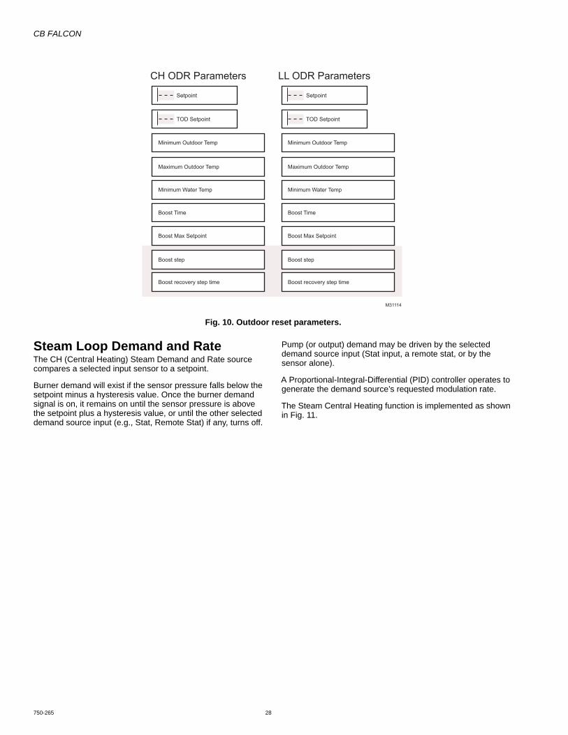
CB FALCON
750-265 28
Fig. 10. Outdoor reset parameters.
Steam Loop Demand and RateThe CH (Central Heating) Steam Demand and Rate source compares a selected input sensor to a setpoint.
Burner demand will exist if the sensor pressure falls below the setpoint minus a hysteresis value. Once the burner demand signal is on, it remains on until the sensor pressure is above the setpoint plus a hysteresis value, or until the other selected demand source input (e.g., Stat, Remote Stat) if any, turns off.
Pump (or output) demand may be driven by the selected demand source input (Stat input, a remote stat, or by the sensor alone).
A Proportional-Integral-Differential (PID) controller operates to generate the demand source’s requested modulation rate.
The Steam Central Heating function is implemented as shown in Fig. 11.
CH ODR Parameters LL ODR Parameters
Setpoint
TOD Setpoint
Minimum Outdoor Temp
Maximum Outdoor Temp
Minimum Water Temp
Boost Time
Boost step
Boost recovery step time
Boost Max Setpoint
Setpoint
TOD Setpoint
Minimum Outdoor Temp
Maximum Outdoor Temp
Minimum Water Temp
Boost Time
Boost step
Boost recovery step time
Boost Max Setpoint
M31114
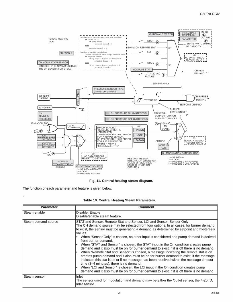
CB FALCON
29 750-265
Fig. 11. Central heating steam diagram.
The function of each parameter and feature is given below.
.
CH BURNERDEMAND
CH HEATDEMAND
CH MODULATION SENSOR
PRESSURE SENSOR TYPE:0-15PSI OR 0-150PSI
MODBUSSTEAM SETPOINT
CH SETPOINT SOURCE
CH MODULATION RATE SOURCE
MODBUSRATE
IGNORED: S1 IS ALWAYS USED ASTHE CH SENSOR FOR STEAM
CH DEMAND SWITCH
MODULUS STAT
PARAMETER
“pRATE” = 0 TO 99.99%OF CAPACITY
INPUT
OUTPUT
CH ENABLE
STEAM HEATING(CH)
CHMINIMUMPRESSURE
TOD
S2 4-20 mA
4-20 mATO SETPOINT
S1 INLET4-20 mA
CH TOD PRESSURESETPOINT
CH PRESSURESETPOINT
CO
NV
ER
SIO
N
STEAM ONLY PARAMETER
CH PRESSURE ON HYSTERESIS
CH PRESSURE OFF HYSTERESIS
A
A
P-GAIN
I-GAIN
D-GAIN
PID
RESTART (RESTART INTEGRATOR WHENEVERA LIMIT OR OVERRIDE ENDS, OR TURN-ON OCCURS.)
1 = S2 4-20mA REMOTE2 = LOCAL3 = MODBUS FUTURE
1 = S2 4-20mA 2 = LOCAL3 = MODBUS 0-FF FUTURE4 = MODBUS 0-200 FUTURE
1
2
3
ERROR SCALING:PRESSURE ERROR ISNORMALIZED: 1.0 PSI ERROR = 1.0˚C ERROR FOR A 150 PSI SENSOR. 0.1 PSI ERROR = 1.0˚C ERROR FOR A 15 PSI SENSOR.WHERE = MEANS “IS EQUIVALENT TO”
TIME SINCE:BURNER TURN-ONBURNER TURN-OFF
BURNERSTATE: ON/OFF
HYSTERESIS
STAT
EnviraCOM REMOTE STAT
LCI
STAT2
J7-3 120 VACFUTURE
FUTURE
FUTURE
SETPOINT DEMAND
SENSOR ONLY
1
2
3
4-20 mATO
pRATE
T
T
T
TT
T
EnviraCOM TOD
TOD
NO DATA TIMEOUTREVERT TO SETPOINT
T
NO DATA TIMEOUTREVERT TO PID
NO DATA TIMEOUTREVERT TO OFF
T
T
Table 10. Central Heating Steam Parameters.
Parameter CommentSteam enable Disable, Enable
Disable/enable steam feature.Steam demand source STAT and Sensor, Remote Stat and Sensor, LCI and Sensor, Sensor Only
The CH demand source may be selected from four options. In all cases, for burner demand to exist, the sensor must be generating a demand as determined by setpoint and hysteresis values.• When “Sensor Only” is chosen, no other input is considered and pump demand is derived
from burner demand.• When “STAT and Sensor” is chosen, the STAT input in the On condition creates pump
demand and it also must be on for burner demand to exist; if it is off there is no demand.• When “Remote Stat and Sensor” is chosen, a message indicating the remote stat is on
creates pump demand and it also must be on for burner demand to exist; if the message indicates this stat is off or if no message has been received within the message timeout time (3–4 minutes), there is no demand.
• When “LCI and Sensor” is chosen, the LCI input in the On condition creates pump demand and it also must be on for burner demand to exist; if it is off there is no demand.
Steam sensor InletThe sensor used for modulation and demand may be either the Outlet sensor, the 4-20mA Inlet sensor.

CB FALCON
750-265 30
Setpoint and Hysteresis (Hydronic)The CH, DHW and LL master each have similar setpoint and hysteresis functions. The parameters for each are separate and independent.
Whenever the burner turns on, the turn-off threshold is raised by 18°F,and then it is decreased in steps. The time of each step is provided by the hysteresis step time parameter. If the time (T) is not-zero, then the following schedule is followed until the off threshold reaches its original value:
Steam pressure setpoint PSI or NoneThis setpoint is used when the time-of-day input is off.
Steam time-of-day pressure setpoint
PSI or NoneThis setpoint is used when the time-of-day input (J10 terminal 2) is on.
Steam Pressure off hysteresisSteam Pressure on hysteresis
PSI or NoneThe off hysteresis is added to the setpoint pressure to determine the pressure at which the demand turns off.Similarly, the on hysteresis is subtracted from the setpoint to determine the pressure at which demand turns on. These may be set to None to indicate that no hysteresis has been defined.The On and Off hysteresis are adjusted at the time the burner changes from off to on, and from on to off, as shown in Fig. 12. This gives the PID algorithm some room to be more aggressive in tracking the load, which can result in overshoot (or undershoot). (see the Setpoint and Hysteresis section, page 31)
Steam hysteresis step time secondsTime of each step. A step time of zero - disables this feature. (see the Setpoint and Hysteresis section, page 31)
Steam P-gainSteam I-gainSteam D-gain
0-100These parameters are the gains applied to the proportional, integral, and differential terms of the PID equation for the Steam loop.
Steam 4-20mA remote control Disable, Setpoint, ModulationDisable: When the value is “Disable,” the 4-20mA input via the Header is ignored and both of the remote control functions are disabled.Modulation: When the burner is free to modulate during the Run state, the 4-20mA input from the Header input becomes the modulation source, where 4mA corresponds to the Minimum modulation rate and 20mA corresponds to the Maximum modulation rate. All other behavior remains as it was; the setpoint and the on/off hysteresis values are still used to determine the burner-on and burner-off thresholds, and the TOD will still affect the burner-on and burner-off thresholds, if this is enabled.When the 4-20mA input is faulty (open, shorted, out of range, etc.) the control issues an alert and reverts to using PID output for modulation, as if the 4-20mA function were disabled.Setpoint: This parameter disables the CH outdoor reset function and the setpoint is provided using a linear interpolation of the 4-20mA input value within a range:• Either the CH pressure setpoint or the CH TOD pressure setpoint provides the setpoint for
the 20mA, depending on the state of the TOD input, and the CH minimum pressure provides the setpoint for 4mA.
When the 4-20mA input is faulty (open, shorted, out of range, etc.) the control issues an alert and reverts to using:• For steam either the CH pressure setpoint or the CH TOD pressure setpoint, depending
on the state of the TOD input. Steam 4-20mA remote control hysteresis
n.n mAProvides a hysteresis filter for the 4-20ma remote control input.
CH minimum pressure PSIThis parameter provides the minimum steam pressure used to calculate the 4-20mA control setpoint for 4mA.
20 mA CH pressure PSI or NoneEstablishes the pressures for the end points of the 4-20 mA inputs
Table 10. Central Heating Steam Parameters. (Continued)
Parameter Comment
StepTime since turn-
on Hydronic Turn-off threshold1 0 <= time <1T Setpoint + Off hysteresis + 18°F
2 1T <=time <2T Setpoint + Off hysteresis + 8°F
3 2T <= time <3T Setpoint + Off hysteresis + 6°F
4 3T <=time <4T Setpoint + Off hysteresis + 4°F
5 4T <=time <5T Setpoint + Off hysteresis + 2°F
6 5 <= time Setpoint
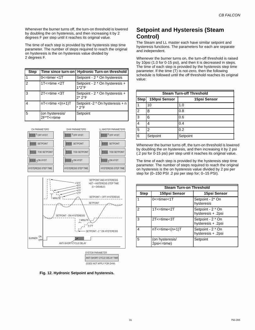
CB FALCON
31 750-265
Whenever the burner turns off, the turn-on threshold is lowered by doubling the on hysteresis, and then increasing it by 2 degrees F per step until it reaches its original value.
The time of each step is provided by the hysteresis step time parameter. The number of steps required to reach the original on hysteresis is the on hysteresis value divided by 2 degrees F.
Fig. 12. Hydronic Setpoint and hysteresis.
Setpoint and Hysteresis (Steam Control)The Steam and LL master each have similar setpoint and hysteresis functions. The parameters for each are separate and independent.
Whenever the burner turns on, the turn-off threshold is raised by 10psi (1.0 for 0-15 psi), and then it is decreased in steps. The time of each step is provided by the hysteresis step time parameter. If the time (T) is not-zero, then the following schedule is followed until the off threshold reaches its original value:
Whenever the burner turns off, the turn-on threshold is lowered by doubling the on hysteresis, and then increasing it by 2 psi (.2 psi for 0-15 psi) per step until it reaches its original value.
The time of each step is provided by the hysteresis step time parameter. The number of steps required to reach the original on hysteresis is the on hysteresis value divided by 2 psi per step for (0–150 PSI .2 psi per step for; 0–15 PSI).
Step Time since turn-on Hydronic Turn-on threshold1 0<=timer <1T Setpoint - 2 * On hysteresis2 1T<=time <2T Setpoint - 2 * On hysteresis +
1*2°F3 2T<=time <3T Setpoint - 2 * On hysteresis +
2* 2°F4 nT<=time <(n+1)T Setpoint -2 * On hysteresis + n
* 2°F5 (on hysteresis/
2F*T<=timeSetpoint
SETPOINT + OFF HYSTERESIS
SETPOINT
SETPOINT - ON HYSTERESIS
BURNER
+18°F +8°F+6°F+4°F+2°F
1 MINUTE
SETPOINT - 2 * ON HYSTERESIS
1 MINUTE
OFFON
ANTI-SHORT-CYCLE DELAY
SETPOINT AND HYSTERESISHST = HISTERESIS STEP TIME
(0 = DISABLE)
2°F
ANTI SHORT CYCLE DELAY TIME
(DOES NOT APPLY FOR DHW)
TOD SETPOINT
SETPOINT
ON HYST.
OFF HYST.
CH PARAMETERS
SYSTEM PARAMETER
TOD SETPOINT
SETPOINT
ON HYST.
OFF HYST.
DHW PARAMETERS
TOD SETPOINT
HYSTERESIS STEP TIME HYSTERESIS STEP TIME HYSTERESIS STEP TIME
SETPOINT
ON HYST.
OFF HYST.
LL MASTER PARAMETERS
Steam Turn-off ThresholdStep 150psi Sensor 15psi Sensor1 10 1.02 8 0.8
3 6 0.6
4 4 0.4
5 2 0.2
6 Setpoint Setpoint
Steam Turn-on ThresholdStep 150psi Sensor 15psi Sensor
1 0<=timer<1T Setpoint - 2* On hysteresis
2 1T<=time<2T Setpoint - 2 * On hysteresis + .2psi
3 2T<=time<3T Setpoint - 2 * On hysteresis + .2psi
4 nT<=time<(n+1)T Setpoint - 2 * On hysteresis + .2psi
5 (on hysteresis/2psi<=time)
Setpoint
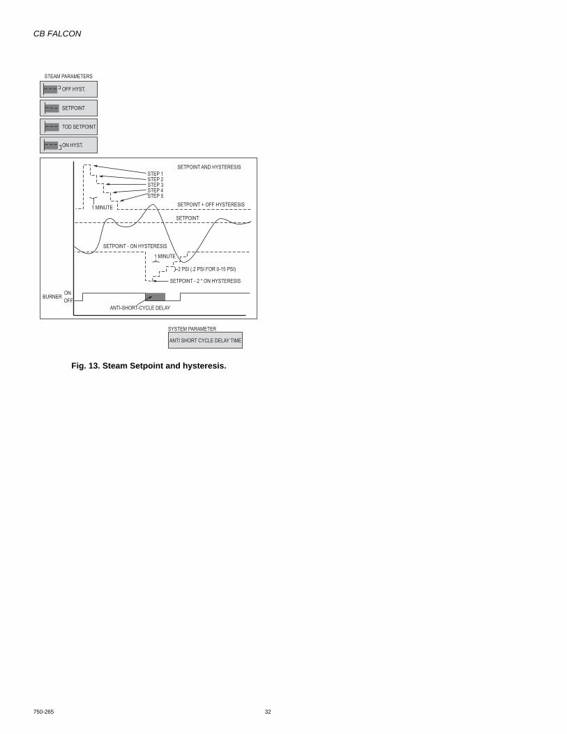
CB FALCON
750-265 32
Fig. 13. Steam Setpoint and hysteresis.
SETPOINT + OFF HYSTERESIS
SETPOINT
SETPOINT - ON HYSTERESIS
BURNER
STEP 1STEP 2STEP 3STEP 4STEP 5
1 MINUTE
SETPOINT - 2 * ON HYSTERESIS
1 MINUTE
OFFON
ANTI-SHORT-CYCLE DELAY
SETPOINT AND HYSTERESIS
2 PSI (.2 PSI FOR 0-15 PSI)
ANTI SHORT CYCLE DELAY TIME
TOD SETPOINT
SETPOINT
ON HYST.
OFF HYST.
STEAM PARAMETERS
SYSTEM PARAMETER

CB FALCON
33 750-265
DHW Loop Demand and Rate (Hydronic only)The Domestic Hot Water (DHW) Demand and Rate source compares a sensor to a setpoint.
A Burner demand will exist if the sensor temperature falls below the setpoint minus a hysteresis value. Once the burner demand signal is on, it remains on until the sensor temperature
is above the setpoint plus a hysteresis value, or until the other selected demand source input (i.e. Remote Stat or DHW Switch), if any, turns off.
Pump demand may be driven by the a remote stat, or by the sensor alone.
A Proportional-Integral-Differential controller operates to generate the source's requested modulation rate.
The DHW function is implemented as shown in Fig. 14.
Fig. 14. Domestic hot water function.
The DHW loop’s ability to override the normal demand priority is described in the System Operation Settings section. Otherwise the behavior of each parameter and feature is given below.
SENSOR
DHW STORAGEPARAMETER
TERMINALS
INPUT OUTPUT
“pRATE” =0 TO 99.99% OF CAPACITY
PASS-THROUGH IF PRIORITY<>DHW STORAGE
DOMESTIC HOT WATER(DHW )
DHW HIGHLIMIT ACTIVE
(SUSPEND DHW DURINGDHW HIGH LIMIT CONDITION)
TO/FROMDHW STORAGE
DHWMODULATIONSENSOR
T
TOD
DATA SERVER “DSD DHW TEMP”
T=x P=1
T=0 P=0
T=1 P=0
T P
PREHEATACTIVE
TOD SETPOINT
SETPOINT
PLATE PREHEATSETPOINT
ON HYST.
PREHEAT
IF PREHEAT IS ACTIVE,USE PREHEAT HYSTERESEIS
PREHEATACTIVE
PREHEATACTIVE
DHW FIRING RATE
(USE MIN MODERATION AND ALSORESTART THE PID INTEGRATOR ATTHE END OF PREHEATING)
OFF HYST.
ON HYST.
NORMAL
OFF HYST.
P-GAIN
I-GAIN
D-GAIN
PID
DHW BURNERDEMAND
DHW HEATDEMAND
DHW DEMAND SWITCH
DATA SERVER DHW OUTPUT ENABLE
DATA SERVER “DSS DHW DEMAND”
DATA SERVER “DSS DHW TEMPERATURE”
SAVE DHW TEMP AND DHWDEMAND IF THIS IS ENABLED ANDTHEY ARE NOT ALREADY COMINGFROM THE DATA SERVER
DATA SERVER “DSD DHW DEMAND”
TIME SINCE:BURNER TURN-ONBURNER TURN-OFF
BURNERSTATE: ON/OFF
HYSTERESIS
STAT
J7-3 120 VAC
EnviraCOM REMOTE STATNO DATATIMEOUT:REVERTTO OFF
SENSOR IS SHORTED
STAT2
SETPOINT DEMAND
SENSOR ONLY
OUTLET (S3S4)
DHW (S6 ONLY)
DHW (S6S7)
INLET (S1)
S6 (DHW TOP)
DHW ENABLE
DHW PLATE DEMAND
T
FUTURE
FUTURE
FUTURE
FUTURE
RESTART (RESTART INTEGRATOR WHENEVERA LIMIT OR OVERRIDE ENDS, OR TURN-ON OCCURS.)
0%
EnviraCOM TOD
TOD
T
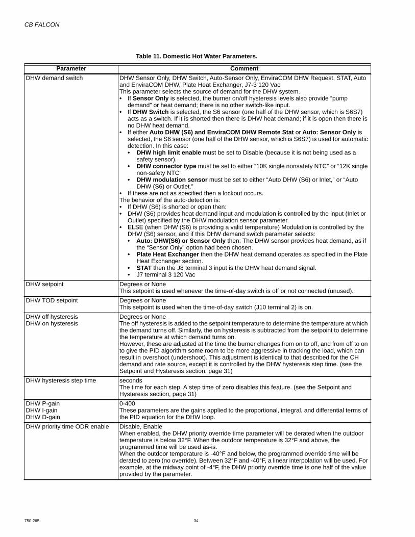
CB FALCON
750-265 34
Table 11. Domestic Hot Water Parameters.
Parameter CommentDHW demand switch DHW Sensor Only, DHW Switch, Auto-Sensor Only, EnviraCOM DHW Request, STAT, Auto
and EnviraCOM DHW, Plate Heat Exchanger, J7-3 120 VacThis parameter selects the source of demand for the DHW system.• If Sensor Only is selected, the burner on/off hysteresis levels also provide “pump
demand” or heat demand; there is no other switch-like input. • If DHW Switch is selected, the S6 sensor (one half of the DHW sensor, which is S6S7)
acts as a switch. If it is shorted then there is DHW heat demand; if it is open then there is no DHW heat demand.
• If either Auto DHW (S6) and EnviraCOM DHW Remote Stat or Auto: Sensor Only is selected, the S6 sensor (one half of the DHW sensor, which is S6S7) is used for automatic detection. In this case:• DHW high limit enable must be set to Disable (because it is not being used as a
safety sensor).• DHW connector type must be set to either “10K single nonsafety NTC” or “12K single
non-safety NTC”• DHW modulation sensor must be set to either “Auto DHW (S6) or Inlet,” or “Auto
DHW (S6) or Outlet.”• If these are not as specified then a lockout occurs.The behavior of the auto-detection is:• If DHW (S6) is shorted or open then:• DHW (S6) provides heat demand input and modulation is controlled by the input (Inlet or
Outlet) specified by the DHW modulation sensor parameter.• ELSE (when DHW (S6) is providing a valid temperature) Modulation is controlled by the
DHW (S6) sensor, and if this DHW demand switch parameter selects:• Auto: DHW(S6) or Sensor Only then: The DHW sensor provides heat demand, as if
the “Sensor Only” option had been chosen.• Plate Heat Exchanger then the DHW heat demand operates as specified in the Plate
Heat Exchanger section.• STAT then the J8 terminal 3 input is the DHW heat demand signal.• J7 terminal 3 120 Vac
DHW setpoint Degrees or NoneThis setpoint is used whenever the time-of-day switch is off or not connected (unused).
DHW TOD setpoint Degrees or NoneThis setpoint is used when the time-of-day switch (J10 terminal 2) is on.
DHW off hysteresisDHW on hysteresis
Degrees or NoneThe off hysteresis is added to the setpoint temperature to determine the temperature at which the demand turns off. Similarly, the on hysteresis is subtracted from the setpoint to determine the temperature at which demand turns on.However, these are adjusted at the time the burner changes from on to off, and from off to on to give the PID algorithm some room to be more aggressive in tracking the load, which can result in overshoot (undershoot). This adjustment is identical to that described for the CH demand and rate source, except it is controlled by the DHW hysteresis step time. (see the Setpoint and Hysteresis section, page 31)
DHW hysteresis step time secondsThe time for each step. A step time of zero disables this feature. (see the Setpoint and Hysteresis section, page 31)
DHW P-gainDHW I-gainDHW D-gain
0-400These parameters are the gains applied to the proportional, integral, and differential terms of the PID equation for the DHW loop.
DHW priority time ODR enable Disable, EnableWhen enabled, the DHW priority override time parameter will be derated when the outdoor temperature is below 32°F. When the outdoor temperature is 32°F and above, the programmed time will be used as-is. When the outdoor temperature is -40°F and below, the programmed override time will be derated to zero (no override). Between 32°F and -40°F, a linear interpolation will be used. For example, at the midway point of -4°F, the DHW priority override time is one half of the value provided by the parameter.

CB FALCON
35 750-265
Plate Heat ExchangerPlate heat exchanger demand for DHW comes from one of two sources:• Tap Demand - detected primarily as a temperature
decrease rate when hot water is “tapped”, e.g. when a tap is turned on.
• Preheat demand - used to keep a plate exchanger preheated so it is warm enough to be ready to provide hot water, and also so that Tap demand can be detected (it has to be warm if a temperature drop rate is to be detected).
One of the selections for the DHW demand switch parameter is “Plate Heat Exchanger”. This selection acts as an enable for the Tap Demand and Preheat Demand subsystems. If this choice is selected then the logic described in Fig. 15 and Table 13 is used to generate DHW demand; however if this is not selected, then the logic is inactive and does not apply.
Tap DemandFor a plate-type heat exchanger, a set of parameters is used to detect demand when the DHW system is tapped (as in turning on a tap). This tapping is detected either as a drop in DHW temperature that exceeds a certain rate, or as a temperature threshold that is exceeded (on the low side) for a period of time. When either of these events occurs, tap demand becomes True. Once tap demand is True, it remains on for a minimum time. At the end of this time tap demand will end when one of two criteria occurs, based upon comparing the Inlet temperature to the DHW and Outlet temperatures.
Because tap demand has two criteria for starting, and two other criteria for stopping, it is modeled as a Set/Clr block driven by two OR gates, which in turn are connected to the four criteria sources. The tap demand is also modeled to have a “force” input, which forces it to recognize a “Set” event: this is used when Preheat has had control and is now relinquishing this control to Tap demand.
The plate heat exchanger subsystem will operate as shown in Fig. 15
DHW modulation sensor Inlet (S1), Outlet (S3S4), DHW (S6S7), Auto DHW (S6) or Inlet(S1), Auto DHW (S6) or OutletThis parameter selects the source of modulation control for the DHW system. If the selected input is not a temperature (e.g. S1 is steam pressure for a steam control) then an alert occurs and the DHW control subsystem is suspended.• If Inlet is selected then the sensor on J8 terminal 4 provides DHW temperature.• If Outlet is selected then this sensor controls DHW modulation.• If DHW (S6S7) is selected then this sensor controls DHW modulation.• If one of the two Auto: DHW(S6) or Inlet(S1) or DHW(S6) or Outlet options is selected,
then the modulation sensor is determined by the automatic detection function described for the DHW demand switch parameter. • If Auto DHW (S6) or Inlet is selected then the Inlet sensor is used if DHW (S6) is a
heat demand switch input. • If Auto: DHW (S6) or Outlet is selected then the Outlet sensor is used if DHW (S6) is
a heat demand switch input.
Table 11. Domestic Hot Water Parameters. (Continued)
Parameter Comment
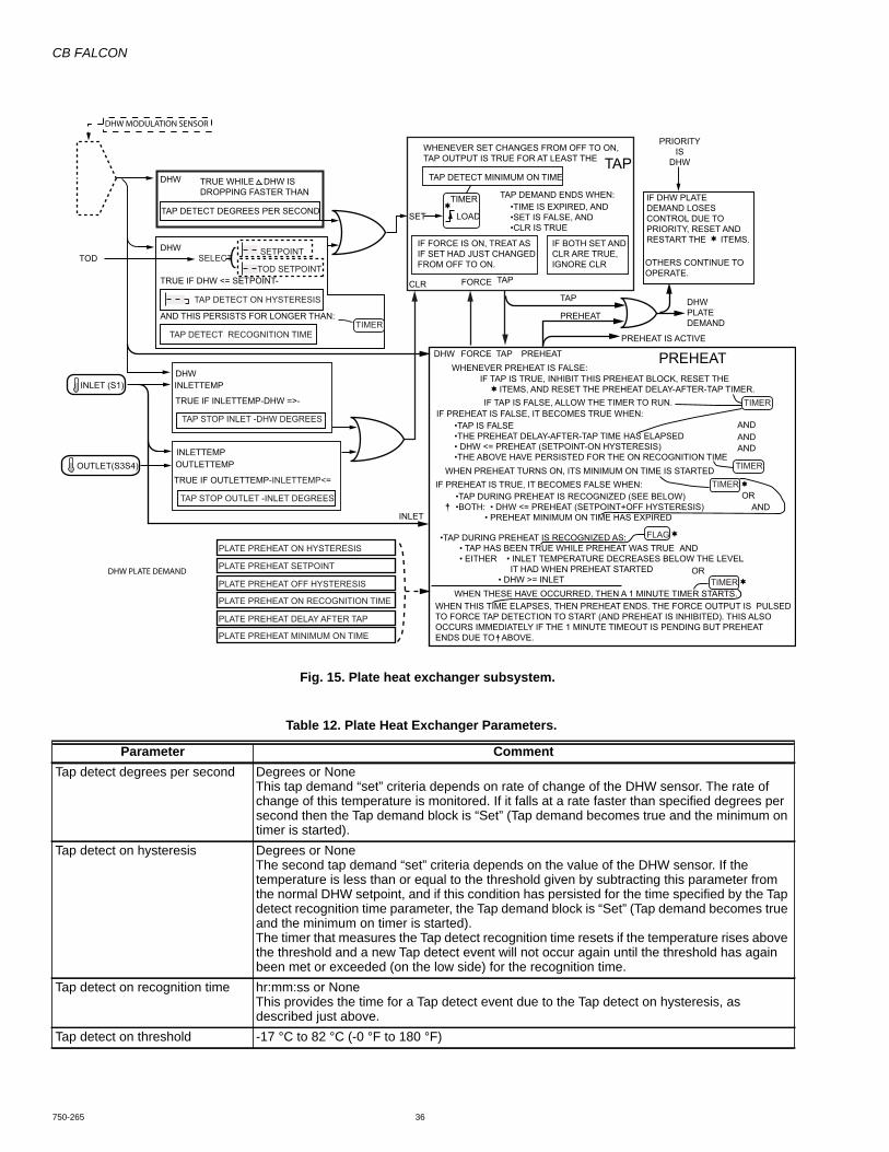
CB FALCON
750-265 36
Fig. 15. Plate heat exchanger subsystem.
Table 12. Plate Heat Exchanger Parameters.
Parameter CommentTap detect degrees per second Degrees or None
This tap demand “set” criteria depends on rate of change of the DHW sensor. The rate of change of this temperature is monitored. If it falls at a rate faster than specified degrees per second then the Tap demand block is “Set” (Tap demand becomes true and the minimum on timer is started).
Tap detect on hysteresis Degrees or NoneThe second tap demand “set” criteria depends on the value of the DHW sensor. If the temperature is less than or equal to the threshold given by subtracting this parameter from the normal DHW setpoint, and if this condition has persisted for the time specified by the Tap detect recognition time parameter, the Tap demand block is “Set” (Tap demand becomes true and the minimum on timer is started).The timer that measures the Tap detect recognition time resets if the temperature rises above the threshold and a new Tap detect event will not occur again until the threshold has again been met or exceeded (on the low side) for the recognition time.
Tap detect on recognition time hr:mm:ss or NoneThis provides the time for a Tap detect event due to the Tap detect on hysteresis, as described just above.
Tap detect on threshold -17 °C to 82 °C (-0 °F to 180 °F)
DHW
DHWTOD
SET
TIMER
LOAD
CLR FORCE TAP
TAP
PREHEAT
PREHEAT IS ACTIVE
TAP DETECT MINIMUM ON TIME
TAP DEMAND ENDS WHEN:
PRIORITYIS
DHW
DHWPLATEDEMAND
ANDANDAND
AND
AND
OR
OR
IF DHW PLATEDEMAND LOSESCONTROL DUE TOPRIORITY, RESET ANDRESTART THE ITEMS.
OTHERS CONTINUE TOOPERATE.
DHW FORCE TAP PREHEATWHENEVER PREHEAT IS FALSE:
IF TAP IS TRUE, INHIBIT THIS PREHEAT BLOCK, RESET THE ITEMS, AND RESET THE PREHEAT DELAY-AFTER-TAP TIMER.
IF PREHEAT IS FALSE, IT BECOMES TRUE WHEN:
WHEN THESE HAVE OCCURRED, THEN A 1 MINUTE TIMER STARTS.WHEN THIS TIME ELAPSES, THEN PREHEAT ENDS. THE FORCE OUTPUT IS PULSEDTO FORCE TAP DETECTION TO START (AND PREHEAT IS INHIBITED). THIS ALSOOCCURS IMMEDIATELY IF THE 1 MINUTE TIMEOUT IS PENDING BUT PREHEATENDS DUE TO ABOVE.
WHEN PREHEAT TURNS ON, ITS MINIMUM ON TIME IS STARTEDIF PREHEAT IS TRUE, IT BECOMES FALSE WHEN:
IF TAP IS FALSE, ALLOW THE TIMER TO RUN.
•TIME IS EXPIRED, AND•SET IS FALSE, AND•CLR IS TRUE
•TAP DURING PREHEAT IS RECOGNIZED AS: • TAP HAS BEEN TRUE WHILE PREHEAT WAS TRUE • EITHER • INLET TEMPERATURE DECREASES BELOW THE LEVEL IT HAD WHEN PREHEAT STARTED • DHW >= INLET
•TAP DURING PREHEAT IS RECOGNIZED (SEE BELOW)•BOTH: • DHW <= PREHEAT (SETPOINT+OFF HYSTERESIS) • PREHEAT MINIMUM ON TIME HAS EXPIRED
•TAP IS FALSE•THE PREHEAT DELAY-AFTER-TAP TIME HAS ELAPSED• DHW <= PREHEAT (SETPOINT-ON HYSTERESIS)•THE ABOVE HAVE PERSISTED FOR THE ON RECOGNITION TIME
WHENEVER SET CHANGES FROM OFF TO ON,TAP OUTPUT IS TRUE FOR AT LEAST THE TAP
PREHEAT
TRUE IF DHW <= SETPOINT-
TRUE IF INLETTEMP-DHW =>-
INLETTEMP
INLET
OUTLETTEMPOUTLET(S3S4)
INLETTEMPINLET (S1)
TRUE IF OUTLETTEMP-INLETTEMP<=
AND THIS PERSISTS FOR LONGER THAN:
DHW
TAP DETECT DEGREES PER SECOND
TRUE WHILE DHW ISDROPPING FASTER THAN
SETPOINTSELECT
TOD SETPOINT
TAP DETECT ON HYSTERESIS
TIMER
PLATE PREHEAT ON HYSTERESIS
PLATE PREHEAT ON RECOGNITION TIME
PLATE PREHEAT DELAY AFTER TAP
PLATE PREHEAT MINIMUM ON TIME
PLATE PREHEAT OFF HYSTERESIS
PLATE PREHEAT SETPOINT
TAP DETECT RECOGNITION TIME
TAP STOP INLET -DHW DEGREES
TAP STOP OUTLET -INLET DEGREES
TIMER
FLAG
TIMER
TIMER
TIMER
IF FORCE IS ON, TREAT ASIF SET HAD JUST CHANGEDFROM OFF TO ON.
IF BOTH SET AND CLR ARE TRUE,IGNORE CLR
DHW PLATE DEMAND
DHW MODULATION SENSOR
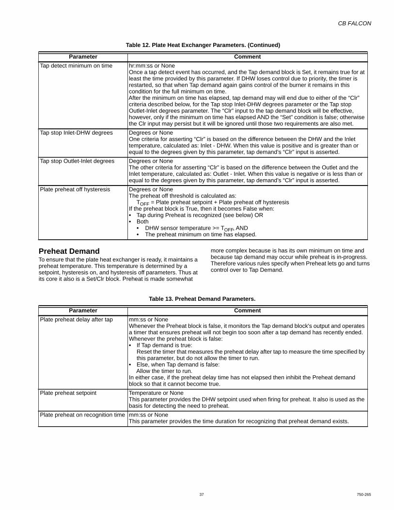
CB FALCON
37 750-265
Preheat DemandTo ensure that the plate heat exchanger is ready, it maintains a preheat temperature. This temperature is determined by a setpoint, hysteresis on, and hysteresis off parameters. Thus at its core it also is a Set/Clr block. Preheat is made somewhat
more complex because is has its own minimum on time and because tap demand may occur while preheat is in-progress. Therefore various rules specify when Preheat lets go and turns control over to Tap Demand.
Tap detect minimum on time hr:mm:ss or NoneOnce a tap detect event has occurred, and the Tap demand block is Set, it remains true for at least the time provided by this parameter. If DHW loses control due to priority, the timer is restarted, so that when Tap demand again gains control of the burner it remains in this condition for the full minimum on time.After the minimum on time has elapsed, tap demand may will end due to either of the “Clr” criteria described below, for the Tap stop Inlet-DHW degrees parameter or the Tap stop Outlet-Inlet degrees parameter. The “Clr” input to the tap demand block will be effective, however, only if the minimum on time has elapsed AND the “Set” condition is false; otherwise the Clr input may persist but it will be ignored until those two requirements are also met.
Tap stop Inlet-DHW degrees Degrees or NoneOne criteria for asserting “Clr” is based on the difference between the DHW and the Inlet temperature, calculated as: Inlet - DHW. When this value is positive and is greater than or equal to the degrees given by this parameter, tap demand’s “Clr” input is asserted.
Tap stop Outlet-Inlet degrees Degrees or NoneThe other criteria for asserting “Clr” is based on the difference between the Outlet and the Inlet temperature, calculated as: Outlet - Inlet. When this value is negative or is less than or equal to the degrees given by this parameter, tap demand’s “Clr” input is asserted.
Plate preheat off hysteresis Degrees or NoneThe preheat off threshold is calculated as:
TOFF = Plate preheat setpoint + Plate preheat off hysteresisIf the preheat block is True, then it becomes False when:• Tap during Preheat is recognized (see below) OR• Both
• DHW sensor temperature >= TOFF, AND• The preheat minimum on time has elapsed.
Table 12. Plate Heat Exchanger Parameters. (Continued)
Parameter Comment
Table 13. Preheat Demand Parameters.
Parameter CommentPlate preheat delay after tap mm:ss or None
Whenever the Preheat block is false, it monitors the Tap demand block's output and operates a timer that ensures preheat will not begin too soon after a tap demand has recently ended. Whenever the preheat block is false:• If Tap demand is true:
Reset the timer that measures the preheat delay after tap to measure the time specified by this parameter, but do not allow the timer to run.
• Else, when Tap demand is false:Allow the timer to run.
In either case, if the preheat delay time has not elapsed then inhibit the Preheat demand block so that it cannot become true.
Plate preheat setpoint Temperature or NoneThis parameter provides the DHW setpoint used when firing for preheat. It also is used as the basis for detecting the need to preheat.
Plate preheat on recognition time mm:ss or NoneThis parameter provides the time duration for recognizing that preheat demand exists.

CB FALCON
750-265 38
Tap During PreheatAlthough preheat cannot become True while Tap demand is true, it is possible that Tap demand may occur after Preheat has started. If the conditions for Tap demand are met, that is, if tap demand does become true during preheat, this is noted by setting the Tap during Preheat flag (which was cleared initially when preheat began).
If this flag is set:• If the Inlet temperature is less than the temperature it had
when preheat started, and the 1 minute timer is not already running, then, a 1 minute timer is started.
• If any of these occur:• The 1 minute timer is running, and it elapses, OR
• The DHW temperature equals or exceeds the Inlet temperature, OR
• Both:DHW sensor temperature >= TOFF, ANDThe preheat minimum on time has expired
• Then:• Tap demand is forced on, that is, a “Set” event is
generated for it, which starts its minimum on timer.
• Preheat becomes false (inactive).
Preheat Modulation controlPreheat provides its own setpoint and hysteresis values. These are used by the burner on/off hysteresis logic in place of the normal DHW values, as shown in Table 15.
However, the preheat function does not modulate and does not use the PID function. Whenever preheat is active, the minimum modulation rate is used. (As usual, a modulation rate of 0% may be used as an output because this value always will be clipped to the minimum modulation rate by the rate limit section.)
When preheat ends the DHW PID integrator will be restarted since it may have accumulated a value during the preheat time which is not relevant because it was not in control. (This is done in the same way as for the end of an override: preheat is essentially a rate override.)
DHW StorageDHW Storage provides a source of demand for the DHW system that will keep the DHW pump on and maintain the water temperature for a programmable period of time after the normal DHW demand has been satisfied. The DHW storage feature has its own setpoint and hysteresis values, so they can differ from the values used during normal DHW demand.
Plate preheat on hysteresis Degrees or NoneThe preheat on threshold is calculated as:
TON = Plate preheat setpoint - Plate preheat on hysteresisIf the preheat block is False, then it is Set (becomes True) when:
1. Tap demand is false, AND2. The preheat delay-after-tap time has elapsed, AND3. DHW sensor temperature <= TON, AND4. The above have remained true for the time specified by:
Plate preheat on recognition timeThat is, whenever conditions 1, 2, or 3 are not true, a preheat recognition timer is reset. Whenever they are all true then the timer is allowed to run. If the time elapses then the preheat block becomes true (preheat is active, and this causes the plate demand to be true).Whenever preheat first becomes active, the Inlet temperature is sampled and saved, a Tap during Preheat flag is cleared, and a 1 minute timer is marked as inactive. (All of these are used by the Tap during Preheat logic.)Whenever preheat demand becomes true, a minimum on timer is started to measure the time specified by the Plate preheat minimum on time parameter. Preheat demand will remain true until this time elapses (except that it may convert to Tap demand under the conditions described for “Tap during Preheat”). If preheat loses control of the burner due to priority, the minimum on timer will be restarted so that it provides the full minimum on time, when priority returns to preheat.
Plate preheat minimum on time mm:ss or NoneThis parameter provides the minimum on time for preheating.
Plate preheat off hysteresis Degrees or NoneThe preheat off threshold is calculated as:
TOFF = Plate preheat setpoint + Plate preheat off hysteresisIf the preheat block is True, then it becomes False when:• Tap during Preheat is recognized (see below) OR• Both
• DHW sensor temperature >= TOFF, AND• The preheat minimum on time has elapsed.
Table 13. Preheat Demand Parameters. (Continued)
Parameter Comment
Table 14. Preheat Modulation Values.
Preheat Inactive Preheat is activeSetpoint DHW setpoint Plate preheat setpointHysteresis On DHW off hysteresis Plate preheat on
hysteresisHysteresis Off DHW off hysteresis Plate preheat on
hysteresis
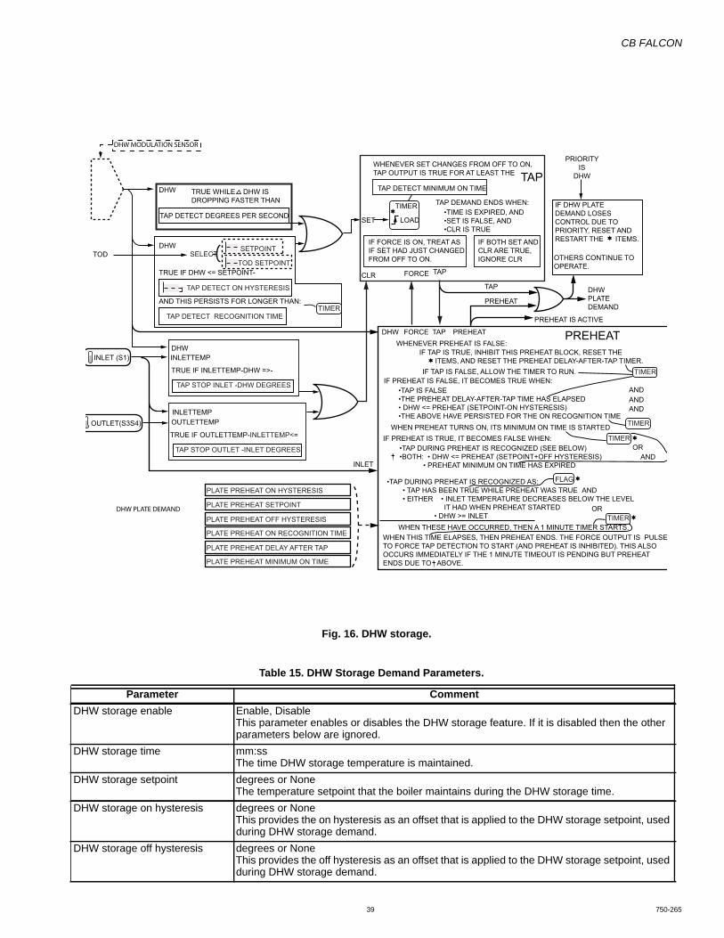
CB FALCON
39 750-265
Fig. 16. DHW storage.
Table 15. DHW Storage Demand Parameters.
Parameter CommentDHW storage enable Enable, Disable
This parameter enables or disables the DHW storage feature. If it is disabled then the other parameters below are ignored.
DHW storage time mm:ssThe time DHW storage temperature is maintained.
DHW storage setpoint degrees or NoneThe temperature setpoint that the boiler maintains during the DHW storage time.
DHW storage on hysteresis degrees or NoneThis provides the on hysteresis as an offset that is applied to the DHW storage setpoint, used during DHW storage demand.
DHW storage off hysteresis degrees or NoneThis provides the off hysteresis as an offset that is applied to the DHW storage setpoint, used during DHW storage demand.
DHW
DHWTOD
SET
TIMER
LOAD
CLR FORCE TAP
TAP
PREHEAT
PREHEAT IS ACTIVE
TAP DETECT MINIMUM ON TIME
TAP DEMAND ENDS WHEN:
PRIORITYIS
DHW
DHWPLATEDEMAND
ANDANDAND
AND
AND
OR
OR
IF DHW PLATEDEMAND LOSESCONTROL DUE TOPRIORITY, RESET ANDRESTART THE ITEMS.
OTHERS CONTINUE TOOPERATE.
DHW FORCE TAP PREHEATWHENEVER PREHEAT IS FALSE:
IF TAP IS TRUE, INHIBIT THIS PREHEAT BLOCK, RESET THE ITEMS, AND RESET THE PREHEAT DELAY-AFTER-TAP TIMER.
IF PREHEAT IS FALSE, IT BECOMES TRUE WHEN:
WHEN THESE HAVE OCCURRED, THEN A 1 MINUTE TIMER STARTS.WHEN THIS TIME ELAPSES, THEN PREHEAT ENDS. THE FORCE OUTPUT IS PULSETO FORCE TAP DETECTION TO START (AND PREHEAT IS INHIBITED). THIS ALSOOCCURS IMMEDIATELY IF THE 1 MINUTE TIMEOUT IS PENDING BUT PREHEATENDS DUE TO ABOVE.
WHEN PREHEAT TURNS ON, ITS MINIMUM ON TIME IS STARTEDIF PREHEAT IS TRUE, IT BECOMES FALSE WHEN:
IF TAP IS FALSE, ALLOW THE TIMER TO RUN.
•TIME IS EXPIRED, AND•SET IS FALSE, AND•CLR IS TRUE
•TAP DURING PREHEAT IS RECOGNIZED AS: • TAP HAS BEEN TRUE WHILE PREHEAT WAS TRUE • EITHER • INLET TEMPERATURE DECREASES BELOW THE LEVEL IT HAD WHEN PREHEAT STARTED • DHW >= INLET
•TAP DURING PREHEAT IS RECOGNIZED (SEE BELOW)•BOTH: • DHW <= PREHEAT (SETPOINT+OFF HYSTERESIS) • PREHEAT MINIMUM ON TIME HAS EXPIRED
•TAP IS FALSE•THE PREHEAT DELAY-AFTER-TAP TIME HAS ELAPSED• DHW <= PREHEAT (SETPOINT-ON HYSTERESIS)•THE ABOVE HAVE PERSISTED FOR THE ON RECOGNITION TIME
WHENEVER SET CHANGES FROM OFF TO ON,TAP OUTPUT IS TRUE FOR AT LEAST THE TAP
PREHEAT
TRUE IF DHW <= SETPOINT-
TRUE IF INLETTEMP-DHW =>-
INLETTEMP
INLET
OUTLETTEMPOUTLET(S3S4)
INLETTEMPINLET (S1)
TRUE IF OUTLETTEMP-INLETTEMP<=
AND THIS PERSISTS FOR LONGER THAN:
DHW
TAP DETECT DEGREES PER SECOND
TRUE WHILE DHW ISDROPPING FASTER THAN
SETPOINTSELECT
TOD SETPOINT
TAP DETECT ON HYSTERESIS
TIMER
PLATE PREHEAT ON HYSTERESIS
PLATE PREHEAT ON RECOGNITION TIME
PLATE PREHEAT DELAY AFTER TAP
PLATE PREHEAT MINIMUM ON TIME
PLATE PREHEAT OFF HYSTERESIS
PLATE PREHEAT SETPOINT
TAP DETECT RECOGNITION TIME
TAP STOP INLET -DHW DEGREES
TAP STOP OUTLET -INLET DEGREES
TIMER
FLAG
TIMER
TIMER
TIMER
IF FORCE IS ON, TREAT ASIF SET HAD JUST CHANGEDFROM OFF TO ON.
IF BOTH SET AND CLR ARE TRUE,IGNORE CLR
DHW PLATE DEMAND
DHW MODULATION SENSOR

CB FALCON
750-265 40
DHW Storage OperationWhen the DHW storage feature is enabled, whenever any normal DHW call-for-heat is satisfied (i.e. pump demand turns off) the DHW storage demand begins and persists for the time given by the DHW storage time parameter. During this time the DHW pump is turned on, and the burner fires as needed to maintain the DHW storage setpoint. DHW storage demand is lower in priority than:• CH demand,• DHW normal demand, and• LL slave demand.
DHW storage demand is higher in priority than:• CH frost protection demand, and• DHW frost protection demand
If another DHW normal demand occurs during the DHW storage time, the storage timer is reset and DHW storage demand begins anew when the DHW normal demand is satisfied. If a CH or LL demand occurs during the DHW storage demand, these take control of the burner; however, the DHW storage timer continues to run. When the higher priority demand is satisfied, then if the DHW storage demand is still active (the time has not yet elapsed) then the boiler again serves the remainder of the DHW storage demand. When the
storage time has expired then DHW storage demand ends and does not recur until a normal DHW demand has recurred and ends. The DHW setpoint and hysteresis are used in the same way as existing setpoints and hysteresis values. This includes use of the DHW hysteresis step time behavior, which modifies the burner on/off thresholds over time.
The gains used by DHW storage are the normal DHW PID gains. This occurs because the DHW PID block is shared by the two demand sources.
• The DHW storage feature, when active, uses the demand source selected by the normal DHW demand source.
• The DHW storage feature, when active, provides setpoint information to the normal DHW PID block, which is used to provide the firing rate when DHW storage is active (i.e. it is shared).
DHW Storage uses the same pump as DHW demand.
The DHW storage feature is shown in Fig. 16.
Frost Protection (Hydronic only)Frost protection, like other sources, generates pump demand and rate.
Fig. 17. CH Frost protection.
The behavior of each parameter and feature is given below.
CH FROST PROTECTIONOUTDOOR TEMPERATURE
CH FROSTPROTECTIONENABLEOVERRUN TIME
LOAD
SET
(CLEAR > SET)CLEAR
SLAVE STATUS
D
CH FROSTPROTECTIONPUMP DEMAND
CH FROSTPROTECTIONBURNER DEMAND
FROM DHWFROST PROTECTIONBURNER DEMAND
SET: < 45°F
CLR: > 50°F
CLR: > T+4°F
T
SET: < T°F
SET: < 38°F
CLR: > 50°F
ON: > 41°F
FROST PROTECTION BURNERDEMAND IS LOW PRIORITY, BUTIT WILL FIRE THE BURNER IF NOOTHER SOURCE IS DOING THAT.
FROST PROTECTION PUMPDEMAND ALWAYS TURNSTHE PUMP ON; THIS IS NEVERBLOCKED BY OTHER FUNCTIONS.
OUTDOOR SENSOR IS OK (OTHERWISE IGNORE IT)
CH FROSTPROTECTIONFIRING RATE
THE FROST PROTECTION FIRINGRATE IS ALWAYS THE MINIMUMMODULATION RATE.
MODULATION SENSOR IS OK (OTHERWISE IGNORE IT)
INLET SENSOR IS OK (OTHERWISE IGNORE IT)
OUTDOOR
SELECTED CHMODULATION
SENSOR
INLET (S1)
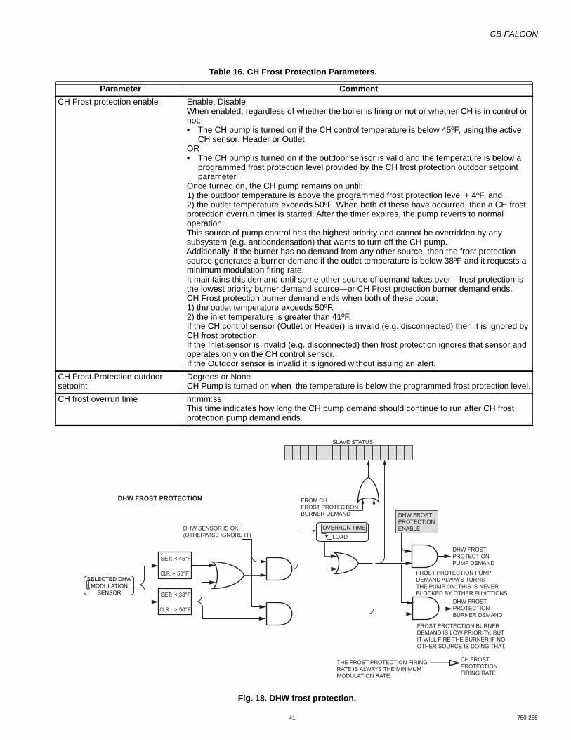
CB FALCON
41 750-265
Fig. 18. DHW frost protection.
Table 16. CH Frost Protection Parameters.
Parameter CommentCH Frost protection enable Enable, Disable
When enabled, regardless of whether the boiler is firing or not or whether CH is in control or not:• The CH pump is turned on if the CH control temperature is below 45ºF, using the active
CH sensor: Header or OutletOR• The CH pump is turned on if the outdoor sensor is valid and the temperature is below a
programmed frost protection level provided by the CH frost protection outdoor setpoint parameter.
Once turned on, the CH pump remains on until:1) the outdoor temperature is above the programmed frost protection level + 4ºF, and2) the outlet temperature exceeds 50ºF. When both of these have occurred, then a CH frost protection overrun timer is started. After the timer expires, the pump reverts to normal operation.This source of pump control has the highest priority and cannot be overridden by any subsystem (e.g. anticondensation) that wants to turn off the CH pump.Additionally, if the burner has no demand from any other source, then the frost protection source generates a burner demand if the outlet temperature is below 38ºF and it requests a minimum modulation firing rate.It maintains this demand until some other source of demand takes over—frost protection is the lowest priority burner demand source—or CH Frost protection burner demand ends.CH Frost protection burner demand ends when both of these occur:1) the outlet temperature exceeds 50ºF.2) the inlet temperature is greater than 41ºF.If the CH control sensor (Outlet or Header) is invalid (e.g. disconnected) then it is ignored by CH frost protection.If the Inlet sensor is invalid (e.g. disconnected) then frost protection ignores that sensor and operates only on the CH control sensor. If the Outdoor sensor is invalid it is ignored without issuing an alert.
CH Frost Protection outdoor setpoint
Degrees or NoneCH Pump is turned on when the temperature is below the programmed frost protection level.
CH frost overrun time hr:mm:ssThis time indicates how long the CH pump demand should continue to run after CH frost protection pump demand ends.
DHW FROST PROTECTION
DHW FROSTPROTECTIONENABLEOVERRUN TIME
LOAD
SLAVE STATUS
DHW FROSTPROTECTIONPUMP DEMAND
DHW FROSTPROTECTIONBURNER DEMAND
FROM CHFROST PROTECTIONBURNER DEMAND
SET: < 45°F
CLR: > 50°F
SET: < 38°F
CLR : > 50°F
FROST PROTECTION BURNERDEMAND IS LOW PRIORITY, BUTIT WILL FIRE THE BURNER IF NOOTHER SOURCE IS DOING THAT.
FROST PROTECTION PUMPDEMAND ALWAYS TURNSTHE PUMP ON; THIS IS NEVERBLOCKED BY OTHER FUNCTIONS.
DHW SENSOR IS OK(OTHERWISE IGNORE IT)
CH FROSTPROTECTIONFIRING RATE
THE FROST PROTECTION FIRINGRATE IS ALWAYS THE MINIMUMMODULATION RATE.
SELECTED DHWMODULATION
SENSOR
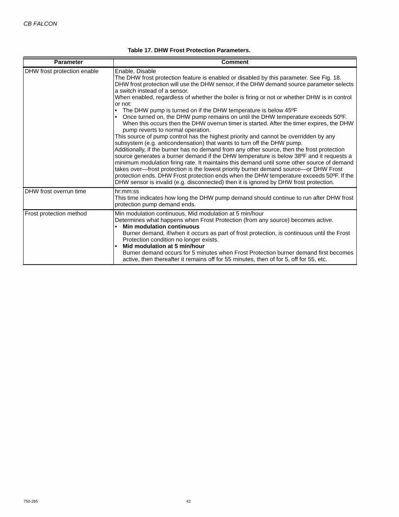
CB FALCON
750-265 42
Table 17. DHW Frost Protection Parameters.
Parameter CommentDHW frost protection enable Enable, Disable
The DHW frost protection feature is enabled or disabled by this parameter. See Fig. 18.DHW frost protection will use the DHW sensor, if the DHW demand source parameter selects a switch instead of a sensor.When enabled, regardless of whether the boiler is firing or not or whether DHW is in control or not:• The DHW pump is turned on if the DHW temperature is below 45ºF• Once turned on, the DHW pump remains on until the DHW temperature exceeds 50ºF.
When this occurs then the DHW overrun timer is started. After the timer expires, the DHW pump reverts to normal operation.
This source of pump control has the highest priority and cannot be overridden by any subsystem (e.g. anticondensation) that wants to turn off the DHW pump.Additionally, if the burner has no demand from any other source, then the frost protection source generates a burner demand if the DHW temperature is below 38ºF and it requests a minimum modulation firing rate. It maintains this demand until some other source of demand takes over—frost protection is the lowest priority burner demand source—or DHW Frost protection ends. DHW Frost protection ends when the DHW temperature exceeds 50ºF. If the DHW sensor is invalid (e.g. disconnected) then it is ignored by DHW frost protection.
DHW frost overrun time hr:mm:ssThis time indicates how long the DHW pump demand should continue to run after DHW frost protection pump demand ends.
Frost protection method Min modulation continuous, Mid modulation at 5 min/hourDetermines what happens when Frost Protection (from any source) becomes active.• Min modulation continuous
Burner demand, if/when it occurs as part of frost protection, is continuous until the Frost Protection condition no longer exists.
• Mid modulation at 5 min/hourBurner demand occurs for 5 minutes when Frost Protection burner demand first becomes active, then thereafter it remains off for 55 minutes, then of for 5, off for 55, etc.
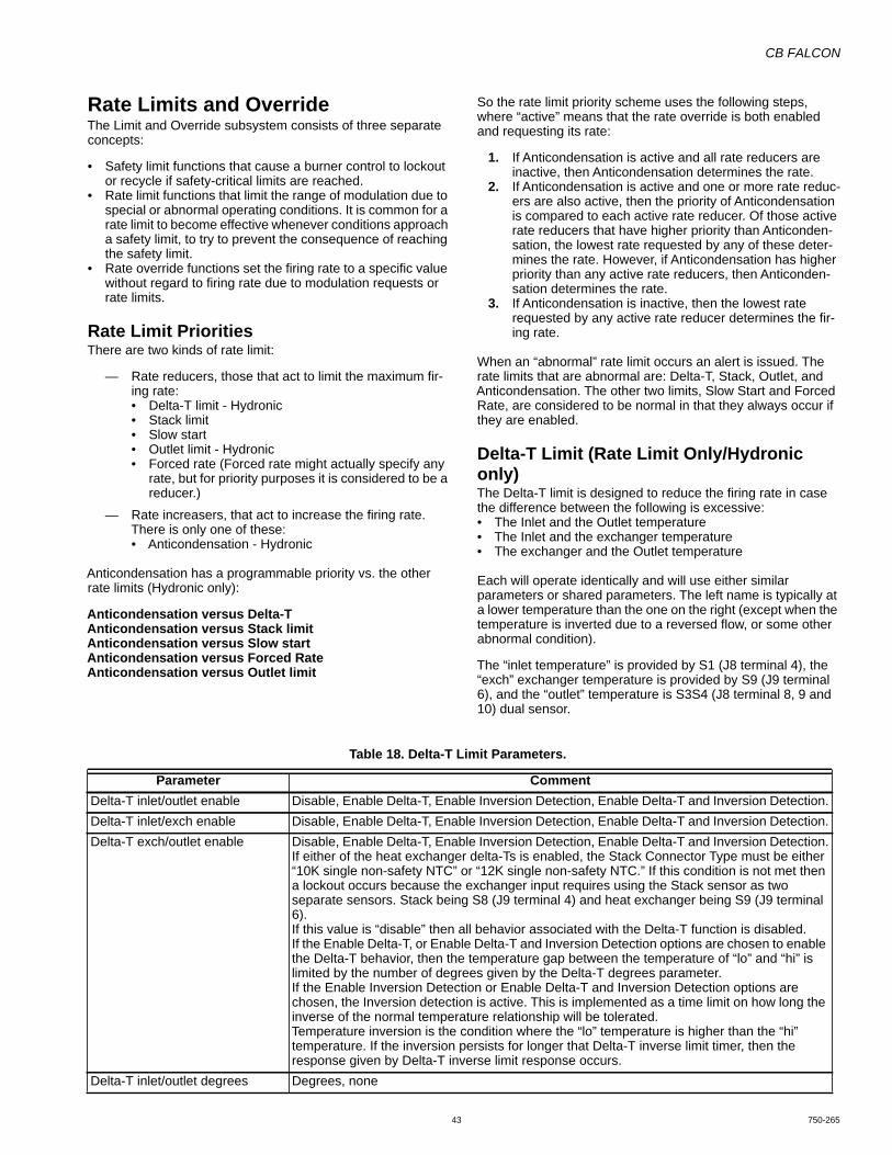
CB FALCON
43 750-265
Rate Limits and OverrideThe Limit and Override subsystem consists of three separate concepts:
• Safety limit functions that cause a burner control to lockout or recycle if safety-critical limits are reached.
• Rate limit functions that limit the range of modulation due to special or abnormal operating conditions. It is common for a rate limit to become effective whenever conditions approach a safety limit, to try to prevent the consequence of reaching the safety limit.
• Rate override functions set the firing rate to a specific value without regard to firing rate due to modulation requests or rate limits.
Rate Limit PrioritiesThere are two kinds of rate limit:
— Rate reducers, those that act to limit the maximum fir-ing rate:• Delta-T limit - Hydronic• Stack limit• Slow start• Outlet limit - Hydronic• Forced rate (Forced rate might actually specify any
rate, but for priority purposes it is considered to be a reducer.)
— Rate increasers, that act to increase the firing rate. There is only one of these:• Anticondensation - Hydronic
Anticondensation has a programmable priority vs. the other rate limits (Hydronic only):
Anticondensation versus Delta-TAnticondensation versus Stack limitAnticondensation versus Slow startAnticondensation versus Forced RateAnticondensation versus Outlet limit
So the rate limit priority scheme uses the following steps, where “active” means that the rate override is both enabled and requesting its rate:
1. If Anticondensation is active and all rate reducers are inactive, then Anticondensation determines the rate.
2. If Anticondensation is active and one or more rate reduc-ers are also active, then the priority of Anticondensation is compared to each active rate reducer. Of those active rate reducers that have higher priority than Anticonden-sation, the lowest rate requested by any of these deter-mines the rate. However, if Anticondensation has higher priority than any active rate reducers, then Anticonden-sation determines the rate.
3. If Anticondensation is inactive, then the lowest rate requested by any active rate reducer determines the fir-ing rate.
When an “abnormal” rate limit occurs an alert is issued. The rate limits that are abnormal are: Delta-T, Stack, Outlet, and Anticondensation. The other two limits, Slow Start and Forced Rate, are considered to be normal in that they always occur if they are enabled.
Delta-T Limit (Rate Limit Only/Hydronic only)The Delta-T limit is designed to reduce the firing rate in case the difference between the following is excessive:• The Inlet and the Outlet temperature• The Inlet and the exchanger temperature• The exchanger and the Outlet temperature
Each will operate identically and will use either similar parameters or shared parameters. The left name is typically at a lower temperature than the one on the right (except when the temperature is inverted due to a reversed flow, or some other abnormal condition).
The “inlet temperature” is provided by S1 (J8 terminal 4), the “exch” exchanger temperature is provided by S9 (J9 terminal 6), and the “outlet” temperature is S3S4 (J8 terminal 8, 9 and 10) dual sensor.
Table 18. Delta-T Limit Parameters.
Parameter CommentDelta-T inlet/outlet enable Disable, Enable Delta-T, Enable Inversion Detection, Enable Delta-T and Inversion Detection.Delta-T inlet/exch enable Disable, Enable Delta-T, Enable Inversion Detection, Enable Delta-T and Inversion Detection.Delta-T exch/outlet enable Disable, Enable Delta-T, Enable Inversion Detection, Enable Delta-T and Inversion Detection.
If either of the heat exchanger delta-Ts is enabled, the Stack Connector Type must be either “10K single non-safety NTC” or “12K single non-safety NTC.” If this condition is not met then a lockout occurs because the exchanger input requires using the Stack sensor as two separate sensors. Stack being S8 (J9 terminal 4) and heat exchanger being S9 (J9 terminal 6).If this value is “disable” then all behavior associated with the Delta-T function is disabled.If the Enable Delta-T, or Enable Delta-T and Inversion Detection options are chosen to enable the Delta-T behavior, then the temperature gap between the temperature of “lo” and “hi” is limited by the number of degrees given by the Delta-T degrees parameter.If the Enable Inversion Detection or Enable Delta-T and Inversion Detection options are chosen, the Inversion detection is active. This is implemented as a time limit on how long the inverse of the normal temperature relationship will be tolerated.Temperature inversion is the condition where the “lo” temperature is higher than the “hi” temperature. If the inversion persists for longer that Delta-T inverse limit timer, then the response given by Delta-T inverse limit response occurs.
Delta-T inlet/outlet degrees Degrees, none

CB FALCON
750-265 44
T-RiseA limit may be imposed on the rate of temperature rise for either the outlet or exchanger temperature, or both.
Delta-T inlet/exch degrees Degrees, noneDelta-T exch/outlet degrees Degrees, none
This is the temperature at which a Delta-T response occurs, measured as the signed value (hi-lo) if the result is negative then it is treated as zero (inversion detection may be enabled to handle this, but that is a different function which does not use this parameter).
All of the Delta-T functions will share the following parameters:Delta-T response Lockout, Recycle & Delay, Recycle & delay with retry limit
This specifies the type of response that occurs when the Delta-T degrees threshold is met. The Recycle & delay with retry limit will limit the number of retries as specified by the Delta-T retry limit.
Delta-T delay mm:ss, noneSpecifies the delay time that occurs whenever a recycle occurs due to a Delta-T or Delta-T inverse event occurs and the specified response includes “Recycle...” The burner will remain in the Standby Hold condition until the delay expires.
Delta-T retry limit number of triesIf either the Delta-T response or the Delta-T inverse limit response specify a retry limit, then any recycles due to reaching the corresponding response threshold are counted. If this count ever exceeds the “n” value, then a lockout occurs.A single counter is used for Delta-T and Inversion Detections, so it could be that different causes occurred to make the counter exceed its final retry limit count of “n” Only the final event that causes the count to exceed the retry limit is annunciated as the cause of the lockout, although each of the reasons for recycling abnormally always generates an alert, as usual, so the presence of other events will be visible in that log.The retry counter is cleared when a normal recycle (burner turn-off) occurs due to satisfying all of the demands.A limit of zero is equivalent to selecting “lockout.”
Delta-T rate limit enable Disable, EnableDisable then no modulation limiting occurs as the delta-T threshold is approached. Enable, then the Stepped Modulation Limiting feature is active for Delta-T.
Delta-T inverse limit time mm:ss or NoneThis provides the time limit during which inverted temperature is tolerated when one of the two inverse detection option is enabled.
Delta-T inverse limit response Lockout, Recycle & Delay, Recycle & delay with retry limit If temperature inversion detection is enabled and it persists for the time given by the Delta-T inverse limit time, then the response described by this parameter occurs.The delay time used is the time specified by the Delta-T delay and the retry limit is the count specified by the Delta-T retry limit.
Table 18. Delta-T Limit Parameters. (Continued)
Parameter Comment
Table 19. T-Rise Parameters.
Parameter CommentOutlet T-Rise enable Disable, Enable
This enables/disables temperature rise detection for the outlet sensor S3 (J8 terminal 8).Exchanger T-Rise enable Disable, Enable
This enables/disables temperature rise detection for the heat exchanger sensor S9 (J9 terminal 6).If this selection is “Enable” then the Stack Connector Type must be either “10K single non-safety NTC” or “12K single non-safety NTC.” If this condition is not met then a lockout occurs because the exchanger input requires using the Stack sensor as two separate sensors. Stack being S8 (J9 terminal 4) and heat exchanger being S9 (J9 terminal 6).
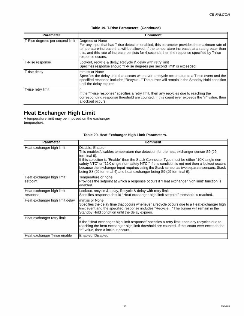
CB FALCON
45 750-265
Heat Exchanger High LimitA temperature limit may be imposed on the exchanger temperature.
T-Rise degrees per second limit Degrees or NoneFor any input that has T-rise detection enabled, this parameter provides the maximum rate of temperature increase that will be allowed. If the temperature increases at a rate greater than this, and this rate of increase persists for 4 seconds then the response specified by T-rise response occurs.
T-Rise response Lockout, recycle & delay, Recycle & delay with retry limitSpecifies response should “T-Rise degrees per second limit” is exceeded.
T-rise delay mm:ss or NoneSpecifies the delay time that occurs whenever a recycle occurs due to a T-rise event and the specified response includes “Recycle...” The burner will remain in the Standby Hold condition until the delay expires.
T-rise retry limit nIf the “T-rise response” specifies a retry limit, then any recycles due to reaching the corresponding response threshold are counted. If this count ever exceeds the “n” value, then a lockout occurs.
Table 19. T-Rise Parameters. (Continued)
Parameter Comment
Table 20. Heat Exchanger High Limit Parameters.
Parameter CommentHeat exchanger high limit Disable, Enable
This enables/disables temperature rise detection for the heat exchanger sensor S9 (J9 terminal 6).If this selection is “Enable” then the Stack Connector Type must be either “10K single non-safety NTC” or “12K single non-safety NTC.” If this condition is not met then a lockout occurs because the exchanger input requires using the Stack sensor as two separate sensors. Stack being S8 (J9 terminal 4) and heat exchanger being S9 (J9 terminal 6).
Heat exchanger high limit setpoint
Temperature or noneProvides the setpoint at which a response occurs if “Heat exchanger high limit” function is enabled.
Heat exchanger high limit response
Lockout, recycle & delay, Recycle & delay with retry limitSpecifies response should “Heat exchanger high limit setpoint” threshold is reached.
Heat exchanger high limit delay mm:ss or NoneSpecifies the delay time that occurs whenever a recycle occurs due to a Heat exchanger high limit event and the specified response includes “Recycle...” The burner will remain in the Standby Hold condition until the delay expires.
Heat exchanger retry limit nIf the “Heat exchanger high limit response” specifies a retry limit, then any recycles due to reaching the heat exchanger high limit threshold are counted. If this count ever exceeds the “n” value, then a lockout occurs.
Heat exchanger T-rise enable Enabled, Disabled
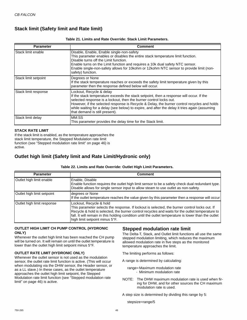
CB FALCON
750-265 46
Stack limit (Safety limit and Rate limit)
STACK RATE LIMITIf the stack limit is enabled, as the temperature approaches the stack limit temperature, the Stepped Modulation rate limit function (see “Stepped modulation rate limit” on page 46) is active.
Outlet high limit (Safety limit and Rate Limit/Hydronic only)
OUTLET HIGH LIMIT CH PUMP CONTROL (HYDRONIC ONLY)Whenever the outlet high limit has been reached the CH pump will be turned on. It will remain on until the outlet temperature is lower than the outlet high limit setpoint minus 5°F.
OUTLET RATE LIMIT (HYDRONIC ONLY)Whenever the outlet sensor is not used as the modulation sensor, the outlet rate limit function is active. (This will occur when modulating via the DHW sensor, the Header sensor, or as a LL slave.) In these cases, as the outlet temperature approaches the outlet high limit setpoint, the Stepped Modulation rate limit function (see “Stepped modulation rate limit” on page 46) is active.
Stepped modulation rate limitThe Delta-T, Stack, and Outlet limit functions all use the same stepped modulation limiting, which reduces the maximum allowed modulation rate in five steps as the monitored temperature approaches the limit.
The limiting performs as follows:
A range is determined by calculating:
range=Maximum modulation rate- Minimum modulation rate
NOTE: The DHW maximum modulation rate is used when fir-ing for DHW, and for other sources the CH maximum modulation rate is used.
A step size is determined by dividing this range by 5:
stepsize=range/5
Table 21. Limits and Rate Override: Stack Limit Parameters.
Parameter CommentStack limit enable Disable, Enable, Enable single-non-safety
This parameter enables or disables the entire stack temperature limit function.Disable turns off the Limit function.Enable turns on the Limit function and requires a 10k dual safety NTC sensor.Enable single-non-safety allows for 10kohm or 12kohm NTC sensor to provide limit (non-safety) function.
Stack limit setpoint Degrees or NoneIf the stack temperature reaches or exceeds the safety limit temperature given by this parameter then the response defined below will occur.
Stack limit response Lockout, Recycle & delayIf the stack temperature exceeds the stack setpoint, then a response will occur. If the selected response is a lockout, then the burner control locks out.However, if the selected response is Recycle & Delay, the burner control recycles and holds while waiting for a delay (see below) to expire, and after the delay it tries again (assuming that demand is still present).
Stack limit delay MM:SSThis parameter provides the delay time for the Stack limit.
Table 22. Limits and Rate Override: Outlet High Limit Parameters.
Parameter CommentOutlet high limit enable Enable, Disable
Enable function requires the outlet high limit sensor to be a safety check dual redundant type.Disable allows for single sensor input to allow steam to use outlet as non-safety.
Outlet high limit setpoint degrees or NoneIf the outlet temperature reaches the value given by this parameter then a response will occur
Outlet high limit response Lockout, Recycle & holdThis parameter selects the response. If lockout is selected, the burner control locks out. If Recycle & hold is selected, the burner control recycles and waits for the outlet temperature to fall. It will remain in this holding condition until the outlet temperature is lower than the outlet high limit setpoint minus 5°F.
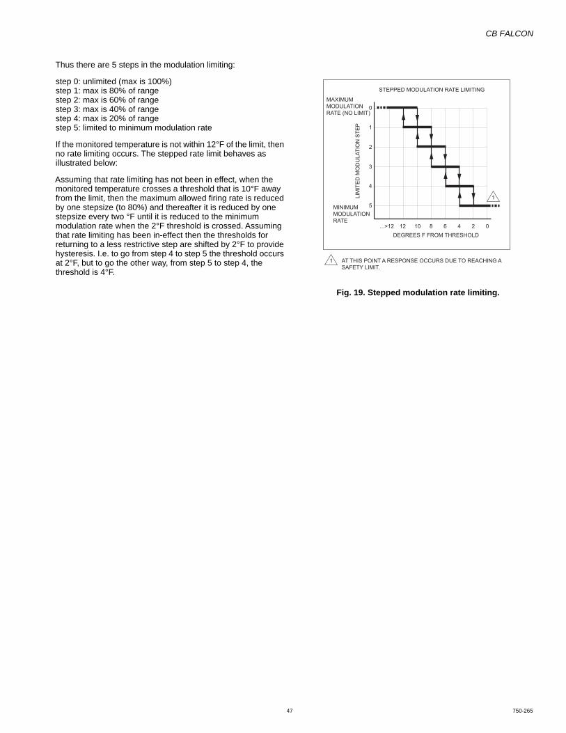
CB FALCON
47 750-265
Thus there are 5 steps in the modulation limiting:
step 0: unlimited (max is 100%)step 1: max is 80% of rangestep 2: max is 60% of rangestep 3: max is 40% of rangestep 4: max is 20% of rangestep 5: limited to minimum modulation rate
If the monitored temperature is not within 12°F of the limit, then no rate limiting occurs. The stepped rate limit behaves as illustrated below:
Assuming that rate limiting has not been in effect, when the monitored temperature crosses a threshold that is 10°F away from the limit, then the maximum allowed firing rate is reduced by one stepsize (to 80%) and thereafter it is reduced by one stepsize every two °F until it is reduced to the minimum modulation rate when the 2°F threshold is crossed. Assuming that rate limiting has been in-effect then the thresholds for returning to a less restrictive step are shifted by 2°F to provide hysteresis. I.e. to go from step 4 to step 5 the threshold occurs at 2°F, but to go the other way, from step 5 to step 4, the threshold is 4°F.
Fig. 19. Stepped modulation rate limiting.
STEPPED MODULATION RATE LIMITING
DEGREES F FROM THRESHOLD
AT THIS POINT A RESPONSE OCCURS DUE TO REACHING A SAFETY LIMIT.
...>12 12 10 6 4 2 0
4
5
2
3
1
0
8
LIM
ITED
MO
DU
LATI
ON
STE
P
MAXIMUMMODULATIONRATE (NO LIMIT)
MINIMUMMODULATIONRATE
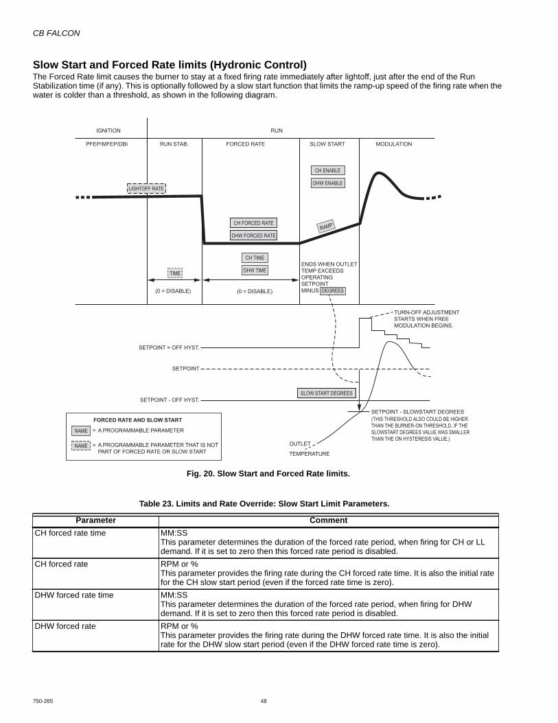
CB FALCON
750-265 48
Slow Start and Forced Rate limits (Hydronic Control)The Forced Rate limit causes the burner to stay at a fixed firing rate immediately after lightoff, just after the end of the Run Stabilization time (if any). This is optionally followed by a slow start function that limits the ramp-up speed of the firing rate when the water is colder than a threshold, as shown in the following diagram.
Fig. 20. Slow Start and Forced Rate limits.
Table 23. Limits and Rate Override: Slow Start Limit Parameters.
Parameter CommentCH forced rate time MM:SS
This parameter determines the duration of the forced rate period, when firing for CH or LL demand. If it is set to zero then this forced rate period is disabled.
CH forced rate RPM or %This parameter provides the firing rate during the CH forced rate time. It is also the initial rate for the CH slow start period (even if the forced rate time is zero).
DHW forced rate time MM:SSThis parameter determines the duration of the forced rate period, when firing for DHW demand. If it is set to zero then this forced rate period is disabled.
DHW forced rate RPM or %This parameter provides the firing rate during the DHW forced rate time. It is also the initial rate for the DHW slow start period (even if the DHW forced rate time is zero).
PFEP/MFEP/DBI RUN STAB. FORCED RATE SLOW START MODULATION
ENDS WHEN OUTLETTEMP EXCEEDSOPERATINGSETPOINTMINUS
TURN-OFF ADJUSTMENTSTARTS WHEN FREEMODULATION BEGINS.
(0 = DISABLE)
SETPOINT = OFF HYST.
SETPOINT - OFF HYST.
A PROGRAMMABLE PARAMETER
A PROGRAMMABLE PARAMETER THAT IS NOTPART OF FORCED RATE OR SLOW START
=
=
FORCED RATE AND SLOW STARTSETPOINT - SLOWSTART DEGREES
OUTLET
TEMPERATURE
SETPOINT
(0 = DISABLE)
IGNITION RUN
LIGHTOFF RATE
TIME
NAME
NAME
DEGREES
CH FORCED RATE
SLOW START DEGREES
DHW FORCED RATE
CH TIME
DHW TIME
CH ENABLE
DHW ENABLE
RAMP
(THIS THRESHOLD ALSO COULD BE HIGHER THAN THE BURNER-ON THRESHOLD, IF THE SLOWSTART DEGREES VALUE WAS SMALLER THAN THE ON HYSTERESIS VALUE.)
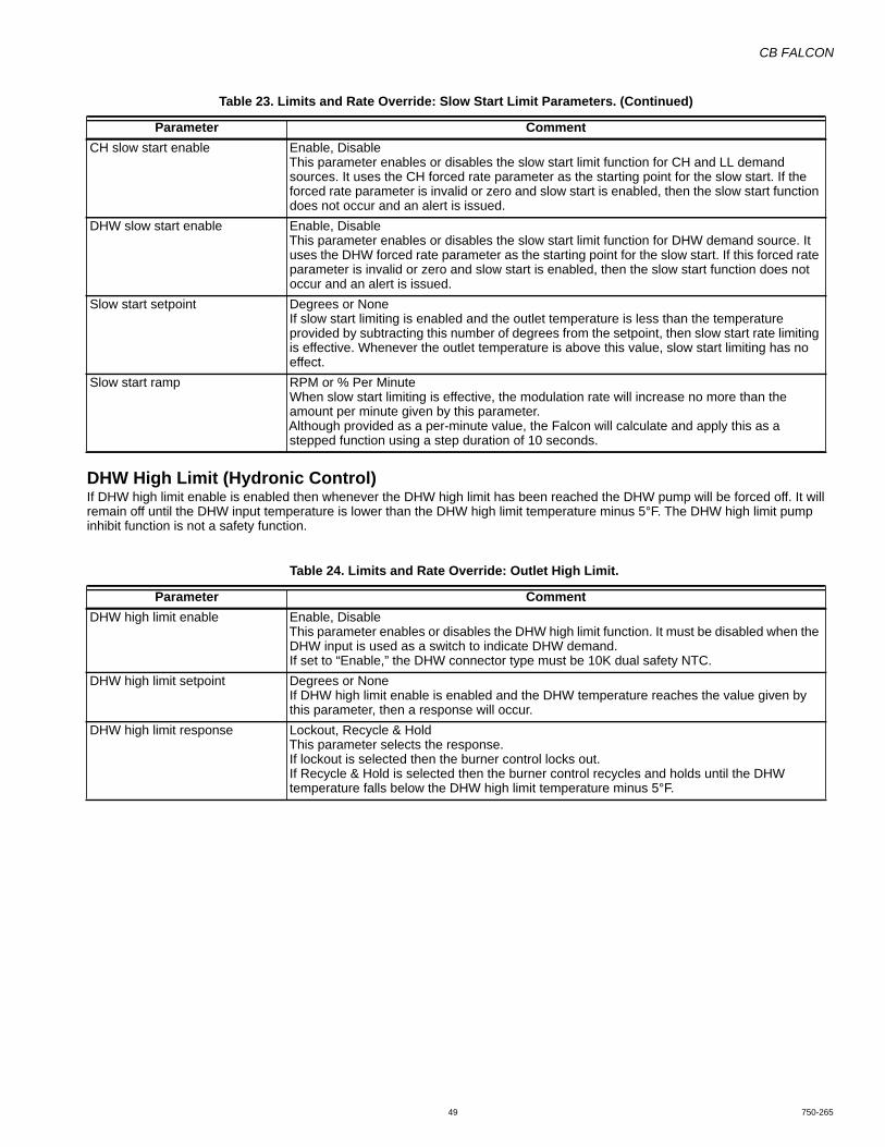
CB FALCON
49 750-265
DHW High Limit (Hydronic Control)If DHW high limit enable is enabled then whenever the DHW high limit has been reached the DHW pump will be forced off. It will remain off until the DHW input temperature is lower than the DHW high limit temperature minus 5°F. The DHW high limit pump inhibit function is not a safety function.
CH slow start enable Enable, DisableThis parameter enables or disables the slow start limit function for CH and LL demand sources. It uses the CH forced rate parameter as the starting point for the slow start. If the forced rate parameter is invalid or zero and slow start is enabled, then the slow start function does not occur and an alert is issued.
DHW slow start enable Enable, DisableThis parameter enables or disables the slow start limit function for DHW demand source. It uses the DHW forced rate parameter as the starting point for the slow start. If this forced rate parameter is invalid or zero and slow start is enabled, then the slow start function does not occur and an alert is issued.
Slow start setpoint Degrees or NoneIf slow start limiting is enabled and the outlet temperature is less than the temperature provided by subtracting this number of degrees from the setpoint, then slow start rate limiting is effective. Whenever the outlet temperature is above this value, slow start limiting has no effect.
Slow start ramp RPM or % Per MinuteWhen slow start limiting is effective, the modulation rate will increase no more than the amount per minute given by this parameter.Although provided as a per-minute value, the Falcon will calculate and apply this as a stepped function using a step duration of 10 seconds.
Table 23. Limits and Rate Override: Slow Start Limit Parameters. (Continued)
Parameter Comment
Table 24. Limits and Rate Override: Outlet High Limit.
Parameter CommentDHW high limit enable Enable, Disable
This parameter enables or disables the DHW high limit function. It must be disabled when the DHW input is used as a switch to indicate DHW demand.If set to “Enable,” the DHW connector type must be 10K dual safety NTC.
DHW high limit setpoint Degrees or NoneIf DHW high limit enable is enabled and the DHW temperature reaches the value given by this parameter, then a response will occur.
DHW high limit response Lockout, Recycle & HoldThis parameter selects the response.If lockout is selected then the burner control locks out.If Recycle & Hold is selected then the burner control recycles and holds until the DHW temperature falls below the DHW high limit temperature minus 5°F.
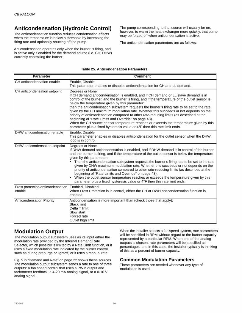
CB FALCON
750-265 50
Anticondensation (Hydronic Control)The anticondensation function reduces condensation effects when the temperature is below a threshold by increasing the firing rate and optionally shutting off the pump.
Anticondensation operates only when the burner is firing, and is active only if enabled for the demand source (i.e. CH, DHW) currently controlling the burner.
The pump corresponding to that source will usually be on; however, to warm the heat exchanger more quickly, that pump may be forced off when anticondensation is active.
The anticondensation parameters are as follows:
Modulation OutputThe modulation output subsystem uses as its input either the modulation rate provided by the Internal Demand/Rate Selector, which possibly is limited by a Rate Limit function, or it uses a fixed modulation rate indicated by the burner control, such as during prepurge or lightoff, or it uses a manual rate.
Fig. 5 in “Demand and Rate” on page 22 shows these sources. The modulation output subsystem sends a rate to one of three outputs: a fan speed control that uses a PWM output and tachometer feedback, a 4-20 mA analog signal, or a 0-10 V analog signal.
When the installer selects a fan speed system, rate parameters will be specified in RPM without regard to the burner capacity represented by a particular RPM. When one of the analog outputs is chosen, rate parameters will be specified as percentages, and in this case, the installer typically is thinking of this as a percent of burner capacity.
Common Modulation ParametersThese parameters are needed whenever any type of modulation is used.
Table 25. Anticondensation Parameters.
Parameter CommentCH anticondensation enable Enable, Disable
This parameter enables or disables anticondensation for CH and LL demand.CH anticondensation setpoint Degrees or None
If CH demand anticondensation is enabled, and if CH demand or LL slave demand is in control of the burner, and the burner is firing, and if the temperature of the outlet sensor is below the temperature given by this parameter:then the anticondensation subsystem requests the burner’s firing rate to be set to the rate given by the CH maximum modulation rate. Whether this succeeds or not depends on the priority of anticondensation compared to other rate-reducing limits (as described at the beginning of “Rate Limits and Override” on page 43).When the CH source sensor temperature reaches or exceeds the temperature given by this parameter plus a fixed hysteresis value or 4°F then this rate limit ends.
DHW anticondensation enable Enable, Disable This parameter enables or disables anticondensation for the outlet sensor when the DHW loop is in control.
DHW anticondensation setpoint Degrees or None If DHW demand anticondensation is enabled, and if DHW demand is in control of the burner, and the burner is firing, and if the temperature of the outlet sensor is below the temperature given by this parameter:• Then the anticondensation subsystem requests the burner’s firing rate to be set to the rate
given by DHW maximum modulation rate. Whether this succeeds or not depends on the priority of anticondensation compared to other rate-reducing limits (as described at the beginning of “Rate Limits and Override” on page 43).
• When the outlet sensor temperature reaches or exceeds the temperature given by this parameter plus a fixed hysteresis value or 4°F then this rate limit ends.
Frost protection anticondensation enable
Enabled, DisabledWhen Frost Protection is in control, either the CH or DWH anticondensation function is enabled.
Anticondensation Priority Anticondensation is more important than (check those that apply):Stack limitDelta T limitSlow startForced rateOutlet high limit

CB FALCON
51 750-265
Fan Speed Modulation ParametersThese parameters are used only when fan speed is selected as the modulation output.
Table 26. Modulation Output Parameters.
Parameter CommentModulation output Fan Speed, 4-20mA, 0-10V
This parameter selects the type of modulation output. The Falcon software responds by driving the appropriate circuit to provide modulation of firing rate.This parameter also affects the interpretation or the type of all parameters which specify rates. These may be provided either as motor RPM or as percentage values, depending on the type of modulation output selected.A programmed value is valid only as a fan speed, or as a percent, but not both. Thus if a system is set up using fan speed values, and then the modulation output parameter is changed to select one of the analog outputs, then all of the fan speeds become “Invalid”. Similarly, parameters that were set up as percentages are invalid when interpreted as fan speeds.
Standby rate RPM or %This parameter specifies the analog output or fan speed used during Standby. If the control is receiving commands via the LL slave module to operate at a given rate, that parameter has higher priority and this parameter is ignored.For a PWM fan system: This rate command will not run the motor.For an analog rate output system:• the output rate is 4mA or 0VElse when Standby rate is non-zero then:• the output rate is determined by the analog output mapping and the mA or V rate analog is
applied to the motor.Prepurge rate RPM or %
This parameter specifies the analog output or fan speed used during prepurge.Lightoff rate RPM or %
This parameter specifies the analog output or fan speed used during ignition.Firing rate control Auto, Manual in Run, Manual in Run and Standby
If this parameter is set to either of the manual options, then the burner’s firing rate during modulation in the Run state is the rate given by the Manual firing rate parameter. If the Manual in Run and Standby option is chosen, the firing rate output is also controlled by the manual firing rate parameter during the Standby condition; however this applies only to the normal, idle Standby condition and not to a Standby Hold condition, wherein the burner is preparing to fire but cannot leave standby because of something abnormal. In the latter case the rate is driven by the burner control sequencer. A manual rate does not generate demand—to fire at this rate demand must be present from another source. When set to “Auto” the manual firing rate parameter is ignored.
Manual firing rate RPM or %This parameter specifies the analog output or fan speed during burner modulation or standby, when firing rate control specifies manual mode.
CH Maximum modulation rateDHW Maximum modulation rateMinimum modulation rate
RPM or %These parameters provide the limits of analog output or fan speed during modulation. The minimum modulation rate is the same for both CH and DHW.
Postpurge rate RPM or %This parameter specifies the analog output or fan speed used during postpurge.
Table 27. Fan Speed Modulation Parameters.
Parameter CommentAbsolute maximum fan speed RPM
The fan will never operate above the RPM provided by this parameter, regardless of the rate request. The maximum speed is 12000 RPM.
Absolute minimum fan speed RPMThe fan will never operate below the RPM provided by this parameter, regardless of the rate request, except by commanding it to turn off. The minimum speed is 500 RPM.
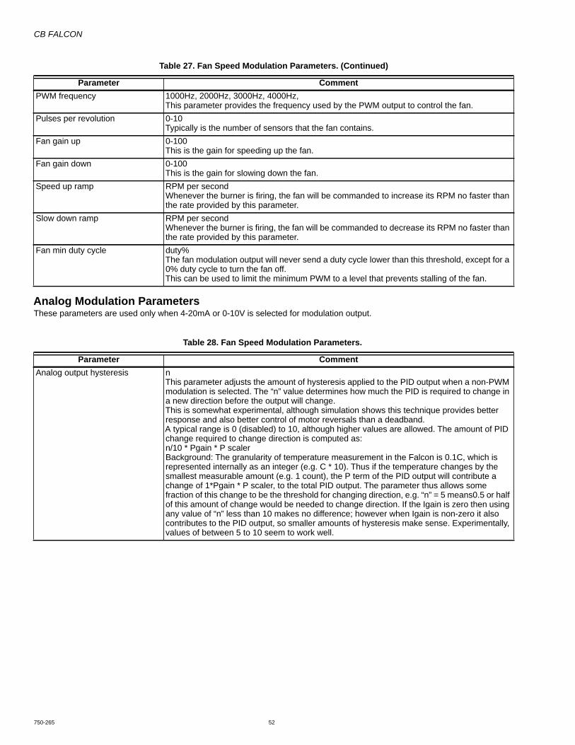
CB FALCON
750-265 52
Analog Modulation ParametersThese parameters are used only when 4-20mA or 0-10V is selected for modulation output.
PWM frequency 1000Hz, 2000Hz, 3000Hz, 4000Hz, This parameter provides the frequency used by the PWM output to control the fan.
Pulses per revolution 0-10Typically is the number of sensors that the fan contains.
Fan gain up 0-100This is the gain for speeding up the fan.
Fan gain down 0-100This is the gain for slowing down the fan.
Speed up ramp RPM per secondWhenever the burner is firing, the fan will be commanded to increase its RPM no faster than the rate provided by this parameter.
Slow down ramp RPM per secondWhenever the burner is firing, the fan will be commanded to decrease its RPM no faster than the rate provided by this parameter.
Fan min duty cycle duty%The fan modulation output will never send a duty cycle lower than this threshold, except for a 0% duty cycle to turn the fan off.This can be used to limit the minimum PWM to a level that prevents stalling of the fan.
Table 28. Fan Speed Modulation Parameters.
Parameter CommentAnalog output hysteresis n
This parameter adjusts the amount of hysteresis applied to the PID output when a non-PWM modulation is selected. The “n” value determines how much the PID is required to change in a new direction before the output will change.This is somewhat experimental, although simulation shows this technique provides better response and also better control of motor reversals than a deadband.A typical range is 0 (disabled) to 10, although higher values are allowed. The amount of PID change required to change direction is computed as:n/10 * Pgain * P scalerBackground: The granularity of temperature measurement in the Falcon is 0.1C, which is represented internally as an integer (e.g. C * 10). Thus if the temperature changes by the smallest measurable amount (e.g. 1 count), the P term of the PID output will contribute a change of 1*Pgain * P scaler, to the total PID output. The parameter thus allows some fraction of this change to be the threshold for changing direction, e.g. “n” = 5 means0.5 or half of this amount of change would be needed to change direction. If the Igain is zero then using any value of “n” less than 10 makes no difference; however when Igain is non-zero it also contributes to the PID output, so smaller amounts of hysteresis make sense. Experimentally, values of between 5 to 10 seem to work well.
Table 27. Fan Speed Modulation Parameters. (Continued)
Parameter Comment

CB FALCON
53 750-265
PUMP CONTROLThere are six identical pump control blocks. Each has a different name but are entirely equal in features and capabilities. For example, if the block named CH Pump were configured to control the DHW pump and vice versa, and the pumps were hooked up that way, both pumps would work normally. Each can be configured for any purpose without regard to the pump name. See Fig. 21.
The pump names are:• Boiler• CH• DHW• Aux1• Aux2• System
Pump control blocks can operate for a local Falcon, a LL Master, or both. Some pump demands are always from the local controller, some from the LL Master and some may come from either source.
The pump overrun timers for frost protection are part of the frost protection block, instead of the pump control block.
Fig. 21. Pump control blocks.
Pump Control Block ParametersEach pump control block implements the parameters described in Table 30, where “XX” is a placeholder for any of the six pump names (CH, DHW, Boiler, System, Aux1, or Aux2).
• Normal pump demand: These bits are in the lower left of Fig. 22, and each of them enable or disable pump demand that flows through the start delay and overrun time, to the “On” connection of the physical device as shown in Fig. 22. This form of pump demand may be inhibited by Force Off.
• Frost pump demand: These bits enable or disable frost protection pump behavior, and these also flow to the “On connection and thus may be inhibited by Force Off.
• Force Off conditions: These bits enable or disable reasons why the pump may be forced off. The force Off conditions flow to the “Force Off” connection to the pump output block, and this signal inhibits the normal pump demand and frost pump demand, but not the Force On conditions.
PU
MP C
RESETIDLE DAYSCOUNTER
COUNTCYCLE
COUNTER
PU
MP B
RESETIDLE DAYSCOUNTER
COUNTCYCLE
COUNTER
CH PUMP OPTIONS 1
CH PUMP START DELAY
CH PUMP OVERUN TIME
CH PUMP OPTIONS 2
PUMP EXERCISE
CH PUMP CYCLE COUNT
CH PUMP CONTROL ON, AUTO
CH PUMPPUMP CONTROL AND OPTIONS
DHW PUMP OPTIONS 1
DHW PUMP START DELAY
DHW PUMP OVERUN TIME
DHW PUMP OPTIONS 2
DHW PUMP OUTPUT CONNECTION, A, B, C
CH PUMP OUTPUT CONNECTION, A, B, C
DHW PUMP CYCLE COUNT
DHW PUMP CONTROL ON, AUTO
DHW PUMP
BOILER PUMP OPTIONS 1
BOILER PUMP START DELAY
BOILER PUMP OVERUN TIME
BOILER PUMP OPTIONS 2
BOILER PUMP OUTPUT CONNECTION, A, B, C
BOILER PUMP CYCLE COUNT
BOILER PUMP CONTROL ON, AUTO
BOILER PUMP
SYSTEM PUMP OPTIONS 1
SYSTEM PUMP START DELAY
SYSTEM PUMP OVERUN TIME
SYSTEM PUMP OPTIONS 2
SYSTEM PUMP OUTPUT CONNECTION, A, B, C
SYSTEM PUMP CYCLE COUNT
SYSTEM PUMP CONTROL ON, AUTO
SYSTEM PUMP
AUX1 PUMP OPTIONS 1
AUX1 PUMP START DELAY
AUX1 PUMP OVERUN TIME
AUX1 PUMP OPTIONS 2
AUX1 PUMP OUTPUT CONNECTION, A, B, C
AUX1 PUMP CYCLE COUNT
AUX1 PUMP CONTROL ON, AUTO
AUX1 PUMP
AUX2 PUMP OPTIONS 1
AUX2 PUMP START DELAY
AUX2 PUMP OVERUN TIME
AUX2 PUMP OPTIONS 2
AUX2 PUMP OUTPUT CONNECTION, A, B, C
AUX2 PUMP CYCLE COUNT
AUX2 PUMP CONTROL ON, AUTO
PARAMETER
SE
E P
umpC
ontrolBlock.cvx FO
R D
ETA
ILS A
BO
UT E
AC
H P
UM
P CO
NR
TOL B
LOC
K
PUMP A
PUMP EXERCISE INTERVAL (DAYS)
PU
MP A
RESETIDLE DAYSCOUNTER
COUNTCYCLE
COUNTER
THERE ARE 6 PUMP CONTROL BLOCKS THAT ARE FUNCTIONALLY IDENTICAL EACH HAS7 PARAMETERS THAT WORK THE SAME WAY IN EACH BLOCK. SEE PumpControlBlock.evxDRAWING FOR DETAILS.
OUTPUT
AUX2 PUMP
PUMP B
PUMP C
IF A PUMP IS IN USE, I.E., IF ITIS CONNECTED TO ANYFUNCTION, AND IF IT HAS NOTBEEN RUN FOR D DAYS, THENTURN IT ON FOR M MINUTES.PARAMETERS(COMMON TO ALL 4):
A FUNCTION (ON THE LEFT) MAYEITHER BE CONNECTED TO ONEPUMP OR NOT CONNECTED AT ALL.IF NOT CONNECTED, IT HASNO EFFECT.
IF MULTIPLE FUNCTIONS ARECONNECTED TO THE SAME PUMP,THEN IF EITHER FUNCTION WANTSTHE PUMP TO BE ON, IT WILL BE ON.(I.E. A LOGICAL OR).
(EITHER OF THESE AS 0 DISABLES)
EXERCISE COMMANDS TO THE CONNECTEDFUNCTION(S). CYCLE COUNTS ARE VISIBLEAS FUNCTIONAL PARAMETERS AND IDLEDAYS COUNTS ARE VISIBLE ASFUNCTION STATUS.
PUMP EXERCISE TIME (MINUTES)

CB FALCON
750-265 54
• Force On conditions: These bits enable or disable reasons why the pump may be forced on. A force on condition flows to the “Force On” connection to the pump output block, and is not inhibited by Force Off.
• General controls: Two of the bits enable or disable general behavior that is not connected to the pump output block.
Fig. 22 shows how a pump control block works when connected to a pump output. The Pump On Options determine the sources that normally turn the pump on. These may be modified by an optional Start Delay and an optional Overrun Time. However, this normal pump on demand may be inhibited by the Force Off options. No matter what the normal Pump On Demand, or the Force Off conditions are requesting, there are Force On options that always turn the pump on.
Fig. 22. Pump control block.
Table 29. Pump Control Block Parameters.
Parameter CommentXX pump output None, Pump A, Pump B, Pump C
This allows the XX pump function to be disconnected or to be attached to any of the pump outputs.If two pump blocks are connected to the same pump output then their signals are effectively OR'd together as shown in Fig. 22.
XX pump control On, AutoThe XX pump can be turned on manually, or it can be set to operate automatically. If it is turned on then it remains on until changed back to Auto.
EXERCISE RUNS THE PUMP IFIT HAS BEEN IDLE TOO LONG ASDEFINED BY PARAMETERSCOMMON TO ALL PUMPS.EXERCISE WILL NOT RUN IF ITIS FORCED OFF.
IF TWO (OR MORE) PUMP CONTROL BLOCKS ARECONNECTED TO THE SAME PUMP OUTPUT,THEN THEIR THREE OUTPUT SIGNALS ON, OFF AND DMD ARE OR’D TOGETHER.THIS PROVIDES THE FOLLOWING BEHAVIOR:
IF EITHER IS FORCE ON, THE PUMP IS ON
NORMAL PUMP DEMAND CAN COME FROM EITHER BLOCK
EITHER CAN INHABIT NORMAL PUMP DEMAND WITH A FORCE OFF
PUMP CONTROL BLOCK PUMP A, B, OR C6 IDENTICAL BLOCKS: CH, DHW, BOILER, SYSTEM, AUX1 & AUX2
USE THIS PUMP FOR LEAD-LAG MASTER DEMANDS
NOTE: THE PUMP CONTROL: AUTO, ONPARAMETER IS ALSO A FORCE ON WHEN SETTO “ON”
USE THIS PUMP FOR STAND-ALONE DEMANDS(BOTH MAY BE CHECKED)
PUMP
START DELAY OVERRUNTIMER
START DELAY TIME TIMER STARTS WHEN THE INPUT TURNS ON TO KEEP THE PUMP OFF FOR AWHILE AT FIRST (BUT ONLY IF BURNER IS JUST STARTING UP)
0=DISABLE OVERRUN TIME TIMER STARTS WHEN THE INPUT TURNS OFFTO KEEP THE PUMP OFF FOR AWHILE AT FIRST(BUT ONLY IF NO OTHER SOURCE CALLS FOR HEAT)
0=DISABLE
MM:SSEXPIRED
DEMANDOPTIONS
FORCE OFFOPTIONS
FORCE ON FORCE ONIF TRUE, THE PUMP WILL BE ON
INHIBITS
PUMPDEMAND
CONNECTION
CYCLE COUNTEDITABLE IN THE FIELD
IN CASE A PUMP IS REPLACED
IDLE DAYS
EXERCISETIMER
CYCLECOUNTER
ON
OFF
DMD
A B C
FORCE OFF
OPTIONS
MM:SS
CYCLE COUNT AND IDLE DAYS BOTHAPPEAR TO BE ATTRIBUTES OF THEPUMP CONTROL BLOCK THAT IS THE PUMPOUTPUT CONNECTED TO, BUT EACH ISACTUALLY PART OF THE PUMP A, B, OR C OUTPUT. FOR EXAMPLE, IF TWO PUMP CONTROL BLOCKS ARE CONNECTED TO THE SAME PUMP, THEIR CYCLE COUNTS ANDIDLE DAYS VALUES WILL BE THE SAMEIN THE TWO PUMP CONTROL BLOCKS.
B
PUMP BON
ON
OFF
DMD
DMD
OFF
BON
DMD
OFF
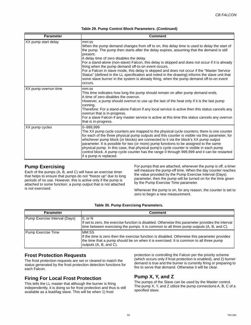
CB FALCON
55 750-265
Pump ExercisingEach of the pumps (A, B, and C) will have an exercise timer that helps to ensure that pumps do not “freeze up” due to long periods of no use. However, this is active only if the pump is attached to some function: a pump output that is not attached is not exercised.
For pumps that are attached, whenever the pump is off, a timer will measure the pump-off time. When the day counter reaches the value provided by the Pump Exercise Interval (Days) parameter, then the pump will be turned on for the time given by the Pump Exercise Time parameter.
Whenever the pump is on, for any reason, the counter is set to zero to begin a new measurement.
Frost Protection RequestsThe frost protection requests are set or cleared to match the status generated by the frost protection detection functions for each Falcon.
Firing For Local Frost ProtectionThis tells the LL master that although the burner is firing independently, it is doing so for frost protection and thus is still available as a lead/lag slave. This will be when 1) frost
protection is controlling the Falcon per the priority scheme (which occurs only if frost protection is enabled), and 2) burner demand is true and the burner is currently firing or preparing to fire to serve that demand. Otherwise it will be clear.
Pump X, Y, and ZThe pumps of the Slave can be used by the Master control. The pump X, Y, and Z utilize the pump connections A, B, C of a specified slave.
XX pump start delay mm:ssWhen the pump demand changes from off to on, this delay time is used to delay the start of the pump. The pump then starts after the delay expires, assuming that the demand is still present.A delay time of zero disables the delay.For a stand-alone (non-slave) Falcon, this delay is skipped and does not occur if it is already firing when the pump demand off-to-on event occurs.For a Falcon in slave mode, this delay is skipped and does not occur if the “Master Service Status” (defined in the LL specification and noted in the drawing) informs the slave unit that some slave burner in the system is already firing, when the pump demand off-to-on event occurs.
XX pump overrun time mm:ssThis time indicates how long the pump should remain on after pump demand ends.A time of zero disables the overrun.However, a pump should overrun to use up the last of the heat only if it is the last pump running.Therefore: For a stand-alone Falcon if any local service is active then this status cancels any overrun that is in-progress.For a slave Falcon if any master service is active at this time this status cancels any overrun that is in-progress.
XX pump cycles 0–999,999The XX pump cycle counters are mapped to the physical cycle counters; there is one counter for each of the three physical pump outputs and this counter is visible via this parameter, for whichever pump block (or blocks) are connected to it via the block's XX pump output parameter. It is possible for two (or more) pump functions to be assigned to the same physical pump. In this case, that physical pump's cycle counter is visible in each pump control block. A pump cycle counter has the range 0 through 999,999 and it can be restarted if a pump is replaced.
Table 29. Pump Control Block Parameters. (Continued)
Parameter Comment
Table 30. Pump Exercising Parameters.
Parameter CommentPump Exercise Interval (Days) 0, or N
If set to zero, the exercise function is disabled. Otherwise this parameter provides the interval time between exercising the pumps. It is common to all three pump outputs (A, B, and C).
Pump Exercise Time MM:SSIf the time is zero then the exercise function is disabled. Otherwise this parameter provides the time that a pump should be on when it is exercised. It is common to all three pump outputs (A, B, and C).
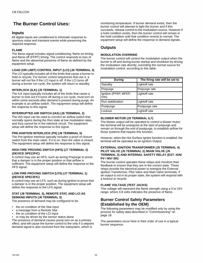
CB FALCON
750-265 56
The Burner Control Uses:
InputsAll digital inputs are conditioned to eliminate response to spurious noise and transient events while preserving the required response.
FLAMEThe flame signal includes signal conditioning, flame-on timing, and flame-off (FFRT) timing. The control responds to loss of flame and the abnormal presence of flame as defined by the equipment setup.
LOAD (OR LIMIT) CONTROL INPUT (LCI) (J6 TERMINAL 3)The LCI typically includes all of the limits that cause a burner to hold or recycle. For burner control sequences that use it, a burner will not fire if the LCI input is off. If the LCI turns off during a burner run cycle, the system will return to standby.
INTERLOCK (ILK) (J5 TERMINAL 1)The ILK input typically includes all of the limits that cause a burner to lock out if it turns off during a run cycle, must turn on within some seconds after demand is present during purge. An example is an airflow switch. The equipment setup will define the response to this signal.
INTERRUPTED AIR SWITCH (IAS) (J6 TERMINAL 2)The IAS input can be used to connect an airflow switch that normally opens during the Run state at low modulation rates, and thus cannot be in the interlock circuit. The equipment setup will define the response to this signal.
PRE-IGNITION INTERLOCK (PII) (J6 TERMINAL 5)The Pre-ignition interlock typically includes a proof of closure switch from the main valve. If it is on, then the valve is closed. The equipment setup will define the response to this signal.
HIGH FIRE PROVING SWITCH (HFS) (J7 TERMINAL 2) (DEVICE SPECIFIC)A control may use an HFS, such as during Prepurge to prove that a damper is in the proper position or that airflow is sufficient. The equipment setup will define the response to the HFS signal.
LOW FIRE PROVING SWITCH (LFS) (J7 TERMINAL 1) (DEVICE SPECIFIC)A control may use an LFS, such as during ignition to prove that a damper is in the proper position. The equipment setup will define the response to the LFS signal.
STAT (J8 TERMINAL 3), REMOTE STAT, AND LCI AS DEMAND INPUTS (J6 TERMINAL 3)The presence of demand may be configured to be:
• the on condition of the Stat input• a message from a Remote Stat• the on condition of the LCI input• or may be driven by the sensor status aloneThe presence of demand causes pump turn-on as a primary effect, and will cause the burner control to fire only if a setpoint demand signal is also received from the subsystem, which is
monitoring temperature. If burner demand exists, then the burner control will attempt to light the burner and if this succeeds, release control to the modulation source. However if a hold condition exists, then the burner control will remain in the hold condition until that condition reverts to normal. The equipment setup will define the response to demand signals.
Outputs
MODULATION OVERRIDEThe burner control will control the modulation output when the burner is off and during burner startup and shutdown by driving the modulation rate directly, overriding the normal source for modulation control, according to this table:
BLOWER MOTOR (J5 TERMINAL 6,7)The blower output will be operated to control a blower motor: the terminal will be energized at the start of prepurge and remain on through the end of postpurge, to establish airflow for those systems that require this function.
However, when the Hot Surface Ignitor function is enabled, the terminal will be operated as an Ignition Output.
EXTERNAL IGNITION TRANSFORMER (J5 TERMINAL 4) PILOT VALVE (J5 TERMINAL 2) /MAIN VALVE (J5 TERMINAL 3) AND INTERNAL SAFETY RELAY (EXT. IGN/ PV / MV/ SR)The burner control operates these relays and monitors their feedback to ensure that they are in the correct state. These relays provide the electrical power to energize the External Ignition Transformer, Pilot Valve and Main Valve terminals. If an output is not in its proper state, the system will respond with a lockout or recycle.
FLAME VOLTAGE (TEST JACKS)This voltage will represent the flame strength using a 0 to 15V range, where 0.8 volts indicates the presence of flame.
Burner Control Safety Parameters(Established by the OEM)The following parameters may be modified only by using the process for safety data described in “Commissioning” on page 18.
The parameters occur here in their order of use in a typical burner sequence.
During The firing rate will be set toStandby Lightoff ratePrepurge Prepurge rateIgnition (PFEP, MFEP, DSI)
Lightoff rate
Run stabilization Lightoff ratePostpurge Postpurge rateLockout Lightoff rate

CB FALCON
57 750-265
Table 31. Burner Control Safety Parameters.
Parameter CommentNTC sensor type 10K dual safety, 12K single non-safety, 10K single non-safety
This parameter determines whether 10K or 12K sensors are used for the Inlet, Outlet, DHW header, Stack, and Outdoor analog sensor inputs. Falcon Steam Control has Stack sensor option only.This parameter also determines whether dual sensors are used with a cross-check for the Outlet, Stack, and DHW sensors. If “10K dual safety” is chosen, these three sensors are each dual 10K sensors, and if they do not track within 6°F then recycle and hold occurs, until the sensors are tracking again.
LCI enable Enable, DisableIf the LCI input is enabled, then the control will check the LCI as a recycle limit. It must be on before the burner control will exit the Standby condition and LCI will cause a recycle if it turns off at other times. If this input is off and demand is present, the burner control will indicate that it is waiting for LCI so the Annunciator can provide a corresponding value in the Annunciator Hold parameter, for use by a display.
PII enable Enable, DisableIf the PII input is enabled, then the control will check the PII as a preignition interlock limit. (As defined by the equipment setup, it typically must be on before the burner control will exit the Standby condition.) If this input is off and the burner control is in a hold condition waiting for it to turn on, then the burner control will indicate that it is waiting for PII so that the Annunciator can provide a corresponding value in the Annunciator Hold parameter, for use by a display.
Interlock start check Enable, DisableIf the Interlock start check is enabled and the fan is off (in some cases it can be on during Standby), then the control will check the ILK input as it exits the Standby condition, in response to demand. If this input is on then the burner control will hold for 120 seconds waiting for it to turn off. If this hold time expires and the ILK is still on, then a lockout occurs.
IAS start check enable Enable, DisableIf the Interrupted Air Switch Enable parameter is set to “Disable” then this parameter is ignored. Otherwise, if the IAS start check is enabled and the fan is off (in some cases it can be on during Standby), then the control will check the IAS input as it exits the Standby condition, in response to demand. If this input is on then the burner control will hold for 120 seconds waiting for it to turn off. If this hold time expires and the IAS is still on, then a lockout occurs.
ILK/IAS open response Lockout, RecycleDuring prepurge after a delay to establish airflow, and during Ignition, MFEP, and Run, the burner control requires the ILK to remain on. If it opens during Ignition, MFEP, or Run then this parameter determines the response: either a lockout or a recycle back to the Safe Start check.If recycle is selected and ILK is open during prepurge: the purge timer is set to zero and the prepurge state holds at time zero, waiting for the ILK to reclose which will resume purge timing. If this hold persists for 30 seconds then the control will go to a Standby Delay condition for 5 minutes, then try again.If the burner control is in a hold condition (but not a Standby Delay) waiting for ILK to turn on, then the burner control will indicate that it is waiting for ILK so that the Annunciator can provide a corresponding value in the Annunciator Hold parameter, for use by a display.
ILK bounce detection enable Enable, DisableInterrupted air switch (IAS) enable
Disable, Purge Only, Purge & IgnitionThis parameter determines when the IAS input is tested. If set to “Disable” then the IAS input is ignored by the burner control, and may be used as an Annunciator input. If set to “Purge Only” then IAS is monitored in the same way as the ILK input, with the same responses, during the Prepurge state. If set to “Purge & Ignition” then IAS is monitored in the same way as the ILK input, with the same responses, during the Prepurge and Ignition states. The IAS in not monitored during Run.
Prepurge time MM:SSThis parameter sets the burner control’s prepurge time. Setting this parameter to zero disables prepurge.

CB FALCON
750-265 58
Fig. 23. Interrupted pilot.
Purge rate proving None, High Fire Switch, Fan SpeedThis parameter determines the input used to confirm the purge rate has been reached. It is unused and ignored if the Prepurge time is set to zero.If set to None, the purge rate is commanded during prepurge but purge timing begins immediately without waiting for any feedback.If set to High Fire Switch then the HFS input must be on to prove the purge rate. Additionally, if this is selected and HFS is already on upon exit from Standby then an additional 30 second prepurge delay (indicating HFS jumpered) is enforced before the measured Prepurge time begins. If the HFS opens during purge, the burner control will react as specified by the equipment setup (typically by restarting or holding Prepurge).If set to Fan Speed then the measured fan speed must be within the specified prepurge rate, +/- 3% for 3 seconds before the rate is proven and the measured prepurge time begins. If the fan speed later goes outside of the prepurge rate +/- 10% during purge, the burner control will react as specified by the equipment setup (typically by restarting or holding Prepurge).
Lightoff rate proving None, Low Fire Switch, Fan SpeedThis parameter determines the input used to confirm the rate has been reached for lighting the burner.If set to None, the lightoff rate is commanded during ignition but is not checked.If set to Low Fire Switch then the LFS input must be on to prove the lightoff rate. Additionally, if this is selected and LFS is already on upon exit from prepurge then an additional 30 second delay (indicating LFS jumpered) is enforced before the Ignition time begins. If the LFS opens during ignition, the burner control will react as specified by the equipment setup (typically by locking out).If set to Fan Speed then the measured fan speed must be within the specified lightoff rate, +/- 3% for 3 seconds before the rate is proven and Ignition begins. If the fan speed later goes outside of the prepurge rate +/- 10% during ignition or MFEP, the burner control will react as specified by the equipment setup (typically by locking out).
Pilot type Interrupted, Intermittent, DBI, Direct Burner Ignition PulsedAn interrupted pilot turns off at the end of the main flame establishing period (MFEP), whereas an intermittent pilot remains on during the run period and thus there is no MFEP. The third choice, DBI (direct burner ignition) indicates that there is no pilot and that the main flame is lit directly using the igniter. The ignition time is fixed at 4 seconds whenever direct burner ignition is selected.
DBI time None, 4 sec, 10 sec, 15 secFlame sensor type Flame Rod, UV, UV with Spark InterferenceForced recycle interval time Time, None
After scheduled time of continuous run, system is recycled, specifically if UV detector is used to provide Safe Start.
Table 31. Burner Control Safety Parameters. (Continued)
Parameter Comment
STANDBY PREPURGEPFEP
EGRUPTSOPNURS51 RO ,01 ,4
FLAME REQUIRED.FAILURE TO IGNITE OPTIONS: • LOCKOUT • COUNT RECYCLES, THEN LOCKOUT • COUNT RECYCLES, THEN DELAY MM:SS • RECYCLE (NO LIMIT)
FLAME REQUIRED: LOCKOUT OR RECYCLE
CLEAR THE FAILURE-TO-IGNITERETRY COUNTER
=
RECYCLE DUE TOFAILURE TO IGNITE
RECYCLE DUE TO FLAMEFAILURE IN MFEP
RECYCLE DUE TO FLAMEFAILURE IN RUN
IGNITERPILOT
MAIN
PREI
GNIT
ION
(MAY
BE
ZERO
)
IGNITER MAY BE ON THROUGHOUT PFEP, OR ONLY DURING FIRST HALF.
MFEP5, 10, OR 15S
RUN STABILIZATION(MAY BE ZERO)
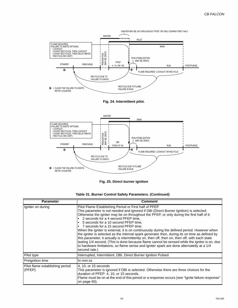
CB FALCON
59 750-265
Fig. 24. Intermittent pilot.
Fig. 25. Direct burner ignition
Table 31. Burner Control Safety Parameters. (Continued)
Parameter CommentIgniter on during Pilot Flame Establishing Period or First half of PFEP
This parameter is not needed and ignored if DBI (Direct Burner Ignition) is selected. Otherwise the igniter may be on throughout the PFEP, or only during the first half of it:• 2 seconds for a 4 second PFEP time,• 5 seconds for a 10 second PFEP time,• 7 seconds for a 15 second PFEP time.When the igniter is external, it is on continuously during the defined period. However when the igniter is selected as the internal spark generator then, during its on time as defined by this parameter, it actually is intermittently on, then off, then on, then off, with each state lasting 1/4 second. (This is done because flame cannot be sensed while the igniter is on, due to hardware limitations, so flame sense and igniter spark are done alternatetly at a 1/4 second rate.)
Pilot type Interrupted, Intermittent, DBI, Direct Burner Ignition PulsedPreignition time hr:mm:ssPilot flame establishing period (PFEP)
4, 10, or 15 secondsThis parameter is ignored if DBI is selected. Otherwise there are three choices for the duration of PFEP: 4, 10, or 15 seconds.Flame must be on at the end of this period or a response occurs (see “Ignite failure response” on page 60).
STANDBY PREPURGEPFEP
NURS51 RO ,01 ,4 POSTPURGE
FLAME REQUIRED.FAILURE TO IGNITE OPTIONS: • LOCKOUT • COUNT RECYCLES, THEN LOCKOUT • COUNT RECYCLES, THEN DELAY MM:SS • RECYCLE (NO LIMIT)
FLAME REQUIRED: LOCKOUT OR RECYCLE
CLEAR THE FAILURE-TO-IGNITERETRY COUNTER
=
RECYCLE DUE TOFAILURE TO IGNITE
RECYCLE DUE TO FLAMEFAILURE IN RUN
IGNITERPILOT
MAIN
PREI
GNIT
ION
(MAY
BE
ZERO
)
IGNITER MAY BE ON THROUGHOUT PFEP, OR ONLY DURING FIRST HALF.
RUN STABILIZATION(MAY BE ZERO)
STANDBY PREPURGEDBI
NURS4 TA DEXIF POSTPURGE
FLAME REQUIRED.FAILURE TO IGNITE OPTIONS: • LOCKOUT • COUNT RECYCLES, THEN LOCKOUT • COUNT RECYCLES, THEN DELAY MM:SS • RECYCLE (NO LIMIT)
FLAME REQUIRED: LOCKOUT OR RECYCLE
CLEAR THE FAILURE-TO-IGNITERETRY COUNTER
=
RECYCLE DUE TOFAILURE TO IGNITE
RECYCLE DUE TO FLAMEFAILURE IN RUN
IGNITERMAIN
PREI
GNIT
ION
(MAY
BE
ZERO
)
RUN STABILIZATION(MAY BE ZERO)
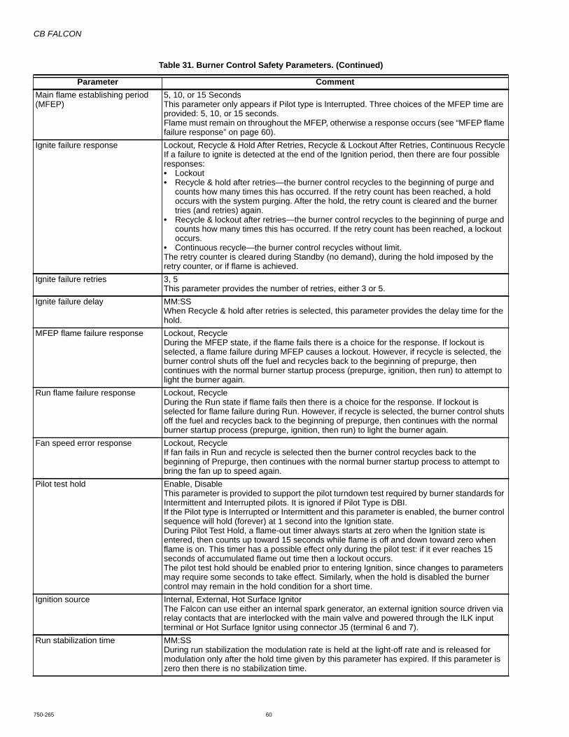
CB FALCON
750-265 60
Main flame establishing period (MFEP)
5, 10, or 15 SecondsThis parameter only appears if Pilot type is Interrupted. Three choices of the MFEP time are provided: 5, 10, or 15 seconds.Flame must remain on throughout the MFEP, otherwise a response occurs (see “MFEP flame failure response” on page 60).
Ignite failure response Lockout, Recycle & Hold After Retries, Recycle & Lockout After Retries, Continuous RecycleIf a failure to ignite is detected at the end of the Ignition period, then there are four possible responses:• Lockout• Recycle & hold after retries—the burner control recycles to the beginning of purge and
counts how many times this has occurred. If the retry count has been reached, a hold occurs with the system purging. After the hold, the retry count is cleared and the burner tries (and retries) again.
• Recycle & lockout after retries—the burner control recycles to the beginning of purge and counts how many times this has occurred. If the retry count has been reached, a lockout occurs.
• Continuous recycle—the burner control recycles without limit.The retry counter is cleared during Standby (no demand), during the hold imposed by the retry counter, or if flame is achieved.
Ignite failure retries 3, 5This parameter provides the number of retries, either 3 or 5.
Ignite failure delay MM:SSWhen Recycle & hold after retries is selected, this parameter provides the delay time for the hold.
MFEP flame failure response Lockout, RecycleDuring the MFEP state, if the flame fails there is a choice for the response. If lockout is selected, a flame failure during MFEP causes a lockout. However, if recycle is selected, the burner control shuts off the fuel and recycles back to the beginning of prepurge, then continues with the normal burner startup process (prepurge, ignition, then run) to attempt to light the burner again.
Run flame failure response Lockout, RecycleDuring the Run state if flame fails then there is a choice for the response. If lockout is selected for flame failure during Run. However, if recycle is selected, the burner control shuts off the fuel and recycles back to the beginning of prepurge, then continues with the normal burner startup process (prepurge, ignition, then run) to light the burner again.
Fan speed error response Lockout, RecycleIf fan fails in Run and recycle is selected then the burner control recycles back to the beginning of Prepurge, then continues with the normal burner startup process to attempt to bring the fan up to speed again.
Pilot test hold Enable, DisableThis parameter is provided to support the pilot turndown test required by burner standards for Intermittent and Interrupted pilots. It is ignored if Pilot Type is DBI.If the Pilot type is Interrupted or Intermittent and this parameter is enabled, the burner control sequence will hold (forever) at 1 second into the Ignition state.During Pilot Test Hold, a flame-out timer always starts at zero when the Ignition state is entered, then counts up toward 15 seconds while flame is off and down toward zero when flame is on. This timer has a possible effect only during the pilot test: if it ever reaches 15 seconds of accumulated flame out time then a lockout occurs.The pilot test hold should be enabled prior to entering Ignition, since changes to parameters may require some seconds to take effect. Similarly, when the hold is disabled the burner control may remain in the hold condition for a short time.
Ignition source Internal, External, Hot Surface IgnitorThe Falcon can use either an internal spark generator, an external ignition source driven via relay contacts that are interlocked with the main valve and powered through the ILK input terminal or Hot Surface Ignitor using connector J5 (terminal 6 and 7).
Run stabilization time MM:SSDuring run stabilization the modulation rate is held at the light-off rate and is released for modulation only after the hold time given by this parameter has expired. If this parameter is zero then there is no stabilization time.
Table 31. Burner Control Safety Parameters. (Continued)
Parameter Comment
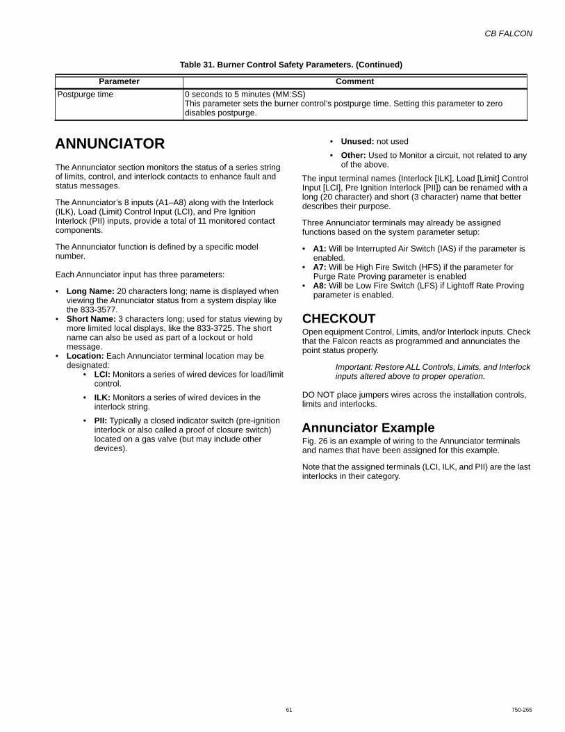
CB FALCON
61 750-265
ANNUNCIATORThe Annunciator section monitors the status of a series string of limits, control, and interlock contacts to enhance fault and status messages.
The Annunciator’s 8 inputs (A1–A8) along with the Interlock (ILK), Load (Limit) Control Input (LCI), and Pre Ignition Interlock (PII) inputs, provide a total of 11 monitored contact components.
The Annunciator function is defined by a specific model number.
Each Annunciator input has three parameters:
• Long Name: 20 characters long; name is displayed when viewing the Annunciator status from a system display like the 833-3577.
• Short Name: 3 characters long; used for status viewing by more limited local displays, like the 833-3725. The short name can also be used as part of a lockout or hold message.
• Location: Each Annunciator terminal location may be designated:
• LCI: Monitors a series of wired devices for load/limit control.
• ILK: Monitors a series of wired devices in the interlock string.
• PII: Typically a closed indicator switch (pre-ignition interlock or also called a proof of closure switch) located on a gas valve (but may include other devices).
• Unused: not used
• Other: Used to Monitor a circuit, not related to any of the above.
The input terminal names (Interlock [ILK], Load [Limit] Control Input [LCI], Pre Ignition Interlock [PII]) can be renamed with a long (20 character) and short (3 character) name that better describes their purpose.
Three Annunciator terminals may already be assigned functions based on the system parameter setup:
• A1: Will be Interrupted Air Switch (IAS) if the parameter is enabled.
• A7: Will be High Fire Switch (HFS) if the parameter for Purge Rate Proving parameter is enabled
• A8: Will be Low Fire Switch (LFS) if Lightoff Rate Proving parameter is enabled.
CHECKOUTOpen equipment Control, Limits, and/or Interlock inputs. Check that the Falcon reacts as programmed and annunciates the point status properly.
Important: Restore ALL Controls, Limits, and Interlock inputs altered above to proper operation.
DO NOT place jumpers wires across the installation controls, limits and interlocks.
Annunciator ExampleFig. 26 is an example of wiring to the Annunciator terminals and names that have been assigned for this example.
Note that the assigned terminals (LCI, ILK, and PII) are the last interlocks in their category.
Postpurge time 0 seconds to 5 minutes (MM:SS)This parameter sets the burner control’s postpurge time. Setting this parameter to zero disables postpurge.
Table 31. Burner Control Safety Parameters. (Continued)
Parameter Comment
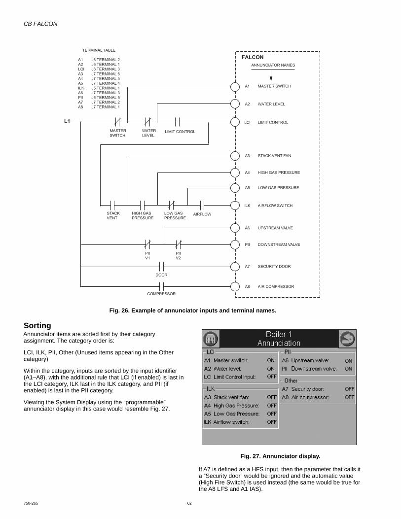
CB FALCON
750-265 62
Fig. 26. Example of annunciator inputs and terminal names.
SortingAnnunciator items are sorted first by their category assignment. The category order is:
LCI, ILK, PII, Other (Unused items appearing in the Other category)
Within the category, inputs are sorted by the input identifier (A1–A8), with the additional rule that LCI (if enabled) is last in the LCI category, ILK last in the ILK category, and PII (if enabled) is last in the PII category.
Viewing the System Display using the “programmable” annunciator display in this case would resemble Fig. 27.
Fig. 27. Annunciator display.
If A7 is defined as a HFS input, then the parameter that calls it a “Security door” would be ignored and the automatic value (High Fire Switch) is used instead (the same would be true for the A8 LFS and A1 IAS).
FALCONANNUNCIATOR NAMES
MASTER SWITCH
WATER LEVEL
LIMIT CONTROL
MASTERSWITCH
WATERLEVEL
LIMIT CONTROL
LCI
ILK
A1
L1
A2
STACK VENT FAN
HIGH GAS PRESSURE
LOW GAS PRESSURE
AIRFLOW SWITCH
STACKVENT
HIGH GASPRESSURE
LOW GASPRESSURE
AIRFLOW
A5
A3
A4
A8
UPSTREAM VALVE
DOWNSTREAM VALVE
SECURITY DOOR
AIR COMPRESSOR
DOOR
COMPRESSOR
A7
A6
PII
PIIV1
PIIV2
TERMINAL TABLE
A1 J6 TERMINAL 2A2 J6 TERMINAL 1LCI J6 TERMINAL 3A3 J7 TERMINAL 6A4 J7 TERMINAL 5A5 J7 TERMINAL 4ILK J5 TERMINAL 1A6 J7 TERMINAL 3PII J6 TERMINAL 5A7 J7 TERMINAL 2A8 J7 TERMINAL 1

CB FALCON
63 750-265
FAULT HANDLING
Lockouts and AlertsThe Falcon implements two kinds of faults: lockouts and alerts.
A list of fault codes with possible troubleshooting tips is provided in Table 50 on page 105.
A list of alerts is provided in Table 51 on page 113.
LOCKOUT• A lockout causes the boiler control to shutdown and
requires manual or remote reset to clear the lockout.• Always causes alarm contacts to close.• Logged in lockout history.
ALERT• Every other kind of problem that isn't a lockout is an alert.
Examples include boiler control abnormal holds, LL master problems, faults from non-safety functions, etc.
• Alerts never require manual intervention to reset them; that is, if the alert clears up, then normal operation will continue. An alert is not a condition, it is an event. The cause of the
alert may be a condition, e.g. something that is causing an abnormal hold, but the alert itself in this case is a momentary event generated upon entry to that condition.
• Whether the alarm contact closes or not is programmable for each alert by the OEM.
• Alerts are logged in a 15-item volatile alert history sorted in chronological order. Only one instance of each alert code occurs in the history, corresponding to the most recent occurrence of that alert.
Alarms for AlertsThe Alarm Parameter Control Block (see the section above) determines which alerts will cause an alarm (by closing the alarm contacts) and which will be reported silently.
Thus an alarm might be on because of a lockout or an alert. If the cause is a lockout then the alarm contacts remain close until the lockout is cleared. However, for alarms due to alerts (which may recur) the alarm may be silenced for a period of time (0–600 minutes) by specifying it in the Alarm Silence Time parameter.
CB FALCON
750-265 64
BURNER CONTROL OPERATION
Safety Shutdown of Burner Control FunctionsSafety Shutdown (Lockout) occurs if any of the following occur during the indicated period:
1. INITIATE Period:a. A/C line power errors occurred.b. Four minute INITIATE period has been exceeded.
2. STANDBY Period:a. Flame signal is present after 240 seconds.b. Preignition Interlock is open an accumulative time of
30 seconds.c. Interlock Start check feature is enabled and the Inter-
lock String (including Airflow Switch) is closed for 120 seconds with the controller closed. (jumpered or welded Interlock).
d. Pilot Valve Terminal is energized.e. Main Valve Terminal is energized.f. Internal system fault occurred.
3. PREPURGE Period:a. Preignition Interlock opens anytime during PRE-
PURGE period.b. Flame signal is detected for 10 seconds accumu-
lated time during PREPURGE.c. Purge Rate Fan RPM or High Fire Switch fails to
close within four minutes and fifteen seconds after the firing rate motor is commanded to drive to the high fire position at the start of PREPURGE.
d. Light off Rate Fan RPM or Low Fire Switch fails to close within four minutes and fifteen seconds after the firing rate motor is commanded to drive to the low fire position at the end of PREPURGE.
e. Lockout Interlock (if programmed) does not close within 10 seconds.
f. Lockout Interlock opens during PREPURGE.g. Pilot Valve terminal is energized.h. Main Valve terminal is energized.i. Internal system fault occurred.
4. PRE-IGNITION TIMEa. Lockout Interlock opens.b. IAS Purge and Ignition enabled and the Interlock
opens.c. Preignition Interlock opens.d. Pilot Valve terminal is energized.e. Main Valve terminal is energized.
5. PILOT FLAME ESTABLISHING PERIOD (PFEP)a. Low Fire Switch opens (if enabled).b. Lockout Interlock opens (if enabled).c. Pilot Valve terminal is not energized.d. No flame is present at the end of the PFEP, or after
programmed number of retry attempts.e. Main valve terminal is energized.f. Internal system fault occurred.
6. MAIN FLAME ESTABLISHING PERIOD (MFEP).a. Low Fire Switch opens (if enabled).b. Lockout Interlock opens (if enabled).c. Pilot valve terminal is not energized.d. Main valve terminal is not energized.e. No flame present at the end of MFEP.f. Internal system fault occurred.
7. RUN Period:
a. No flame is present, or flame is lost (if enabled-lock-out).
b. Lockout Interlock opens) if enabled).c. IAS Purge and Ignition enabled and the Interlock
opens.d. Pilot terminal energized (if programmed as Inter-
rupted Pilot).e. Main valve terminal is not energized.f. Internal system fault occurred.
8. POSTPURGE Period.a. Preignition Interlock does not close in five seconds.b. Pilot Valve terminal is energized.c. Main Valve terminal is energized.d. Internal system fault occurred.e. Flame sensed 240 seconds accumulated time after
the RUN period.
Safety Shutdown1. If the lockout interlocks open or a sensor designated as a
safety limit are read as defective, Falcon will lockout and the blower motor will be de-energized.
If these open during the firing period, all fuel valves will be de-energized, the system will complete postpurge, and will lockout indicated by an alarm.
2. If the pilot flame is not detected by the end of the last (X number recycle attempt), pilot trial for ignition period, the pilot valve, and ignition transformer will be de-energized, the system will complete post purge and will lockout indi-cated by an alarm.
3. If the main flame is not detected at the end of the last recycle attempt of the main flame establishing period, all fuel valves will be de-energized, the device will complete postpurge, and will lockout indicated by an alarm.
4. If the flame sensing signal is lost during the run period (if lockout is selected), all fuel valves will be de-energized within 4 seconds after the loss of the flame signal, the device will complete postpurge, and will lockout indicate by an alarm.
5. Manual reset is required following any safety shutdown. Manual reset may be accomplished by pressing the push button on the device, pressing the remote reset wired into connector J10, or through an attached display.
Interrupting power to Falcon will cause electrical resets, but does not reset a lockout condition.
Operational Sequence
InitiateThe Falcon enters the Initiate sequence on Initial Power up or:• Voltage fluctuations vary less than 20Vac or greater than
30Vac.• Frequency fluctuations vary +/-5% (57 to 63 Hz).• If Demand, LCI, or Stat interrupt (open) during the Prepurge
Period.• After the reset button is pressed or fault is cleared at the
displays.
The Initiate sequence also delays the burner motor from being energized and de-energized from an intermittent AC line input or control input.
If an AC problem exists for more than 240 seconds a lockout will occur.
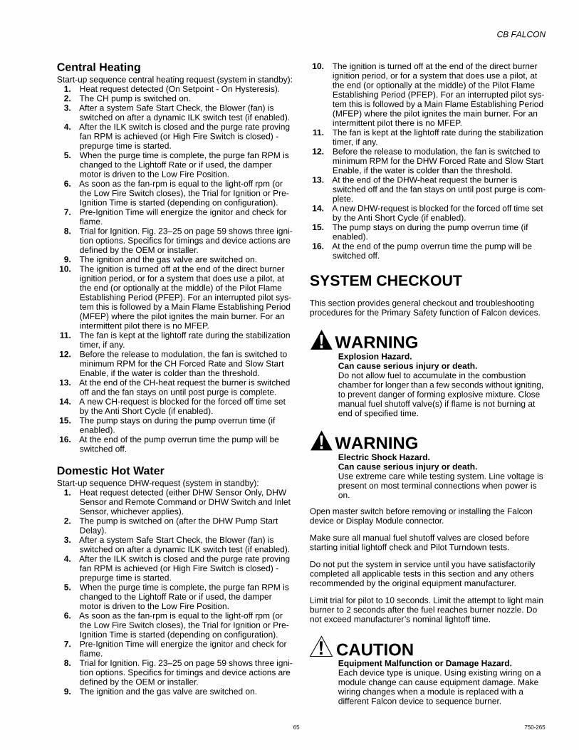
CB FALCON
65 750-265
Central HeatingStart-up sequence central heating request (system in standby):
1. Heat request detected (On Setpoint - On Hysteresis).2. The CH pump is switched on.3. After a system Safe Start Check, the Blower (fan) is
switched on after a dynamic ILK switch test (if enabled).4. After the ILK switch is closed and the purge rate proving
fan RPM is achieved (or High Fire Switch is closed) - prepurge time is started.
5. When the purge time is complete, the purge fan RPM is changed to the Lightoff Rate or if used, the damper motor is driven to the Low Fire Position.
6. As soon as the fan-rpm is equal to the light-off rpm (or the Low Fire Switch closes), the Trial for Ignition or Pre-Ignition Time is started (depending on configuration).
7. Pre-Ignition Time will energize the ignitor and check for flame.
8. Trial for Ignition. Fig. 23–25 on page 59 shows three igni-tion options. Specifics for timings and device actions are defined by the OEM or installer.
9. The ignition and the gas valve are switched on.10. The ignition is turned off at the end of the direct burner
ignition period, or for a system that does use a pilot, at the end (or optionally at the middle) of the Pilot Flame Establishing Period (PFEP). For an interrupted pilot sys-tem this is followed by a Main Flame Establishing Period (MFEP) where the pilot ignites the main burner. For an intermittent pilot there is no MFEP.
11. The fan is kept at the lightoff rate during the stabilization timer, if any.
12. Before the release to modulation, the fan is switched to minimum RPM for the CH Forced Rate and Slow Start Enable, if the water is colder than the threshold.
13. At the end of the CH-heat request the burner is switched off and the fan stays on until post purge is complete.
14. A new CH-request is blocked for the forced off time set by the Anti Short Cycle (if enabled).
15. The pump stays on during the pump overrun time (if enabled).
16. At the end of the pump overrun time the pump will be switched off.
Domestic Hot WaterStart-up sequence DHW-request (system in standby):
1. Heat request detected (either DHW Sensor Only, DHW Sensor and Remote Command or DHW Switch and Inlet Sensor, whichever applies).
2. The pump is switched on (after the DHW Pump Start Delay).
3. After a system Safe Start Check, the Blower (fan) is switched on after a dynamic ILK switch test (if enabled).
4. After the ILK switch is closed and the purge rate proving fan RPM is achieved (or High Fire Switch is closed) - prepurge time is started.
5. When the purge time is complete, the purge fan RPM is changed to the Lightoff Rate or if used, the damper motor is driven to the Low Fire Position.
6. As soon as the fan-rpm is equal to the light-off rpm (or the Low Fire Switch closes), the Trial for Ignition or Pre-Ignition Time is started (depending on configuration).
7. Pre-Ignition Time will energize the ignitor and check for flame.
8. Trial for Ignition. Fig. 23–25 on page 59 shows three igni-tion options. Specifics for timings and device actions are defined by the OEM or installer.
9. The ignition and the gas valve are switched on.
10. The ignition is turned off at the end of the direct burner ignition period, or for a system that does use a pilot, at the end (or optionally at the middle) of the Pilot Flame Establishing Period (PFEP). For an interrupted pilot sys-tem this is followed by a Main Flame Establishing Period (MFEP) where the pilot ignites the main burner. For an intermittent pilot there is no MFEP.
11. The fan is kept at the lightoff rate during the stabilization timer, if any.
12. Before the release to modulation, the fan is switched to minimum RPM for the DHW Forced Rate and Slow Start Enable, if the water is colder than the threshold.
13. At the end of the DHW-heat request the burner is switched off and the fan stays on until post purge is com-plete.
14. A new DHW-request is blocked for the forced off time set by the Anti Short Cycle (if enabled).
15. The pump stays on during the pump overrun time (if enabled).
16. At the end of the pump overrun time the pump will be switched off.
SYSTEM CHECKOUTThis section provides general checkout and troubleshooting procedures for the Primary Safety function of Falcon devices.
WARNINGExplosion Hazard.Can cause serious injury or death.Do not allow fuel to accumulate in the combustion chamber for longer than a few seconds without igniting, to prevent danger of forming explosive mixture. Close manual fuel shutoff valve(s) if flame is not burning at end of specified time.
WARNINGElectric Shock Hazard.Can cause serious injury or death.Use extreme care while testing system. Line voltage is present on most terminal connections when power is on.
Open master switch before removing or installing the Falcon device or Display Module connector.
Make sure all manual fuel shutoff valves are closed before starting initial lightoff check and Pilot Turndown tests.
Do not put the system in service until you have satisfactorily completed all applicable tests in this section and any others recommended by the original equipment manufacturer.
Limit trial for pilot to 10 seconds. Limit the attempt to light main burner to 2 seconds after the fuel reaches burner nozzle. Do not exceed manufacturer’s nominal lightoff time.
CAUTIONEquipment Malfunction or Damage Hazard.Each device type is unique. Using existing wiring on a module change can cause equipment damage. Make wiring changes when a module is replaced with a different Falcon device to sequence burner.
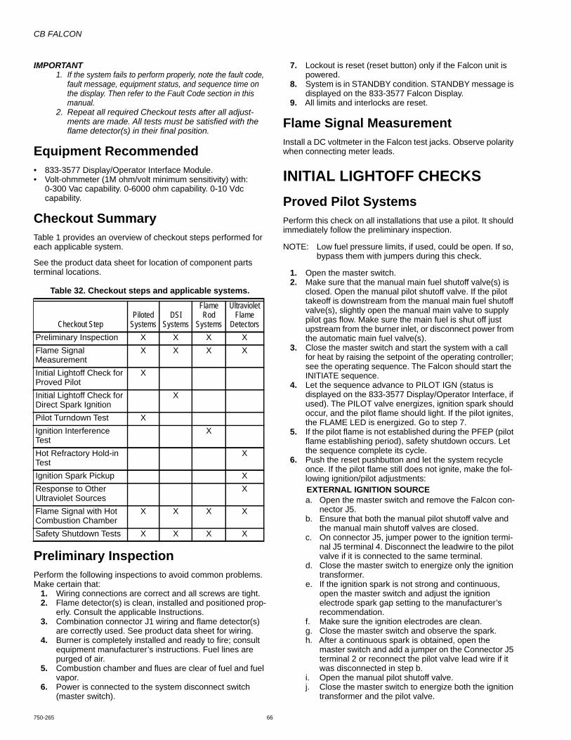
CB FALCON
750-265 66
IMPORTANT 1. If the system fails to perform properly, note the fault code,
fault message, equipment status, and sequence time on the display. Then refer to the Fault Code section in this manual.
2. Repeat all required Checkout tests after all adjust-ments are made. All tests must be satisfied with the flame detector(s) in their final position.
Equipment Recommended• 833-3577 Display/Operator Interface Module.• Volt-ohmmeter (1M ohm/volt minimum sensitivity) with:
0-300 Vac capability. 0-6000 ohm capability. 0-10 Vdc capability.
Checkout SummaryTable 1 provides an overview of checkout steps performed for each applicable system.
See the product data sheet for location of component parts terminal locations.
Table 32. Checkout steps and applicable systems.
Preliminary InspectionPerform the following inspections to avoid common problems. Make certain that:
1. Wiring connections are correct and all screws are tight.2. Flame detector(s) is clean, installed and positioned prop-
erly. Consult the applicable Instructions.3. Combination connector J1 wiring and flame detector(s)
are correctly used. See product data sheet for wiring.4. Burner is completely installed and ready to fire; consult
equipment manufacturer’s instructions. Fuel lines are purged of air.
5. Combustion chamber and flues are clear of fuel and fuel vapor.
6. Power is connected to the system disconnect switch (master switch).
7. Lockout is reset (reset button) only if the Falcon unit is powered.
8. System is in STANDBY condition. STANDBY message is displayed on the 833-3577 Falcon Display.
9. All limits and interlocks are reset.
Flame Signal Measurement Install a DC voltmeter in the Falcon test jacks. Observe polarity when connecting meter leads.
INITIAL LIGHTOFF CHECKSProved Pilot SystemsPerform this check on all installations that use a pilot. It should immediately follow the preliminary inspection.
NOTE: Low fuel pressure limits, if used, could be open. If so, bypass them with jumpers during this check.
1. Open the master switch.2. Make sure that the manual main fuel shutoff valve(s) is
closed. Open the manual pilot shutoff valve. If the pilot takeoff is downstream from the manual main fuel shutoff valve(s), slightly open the manual main valve to supply pilot gas flow. Make sure the main fuel is shut off just upstream from the burner inlet, or disconnect power from the automatic main fuel valve(s).
3. Close the master switch and start the system with a call for heat by raising the setpoint of the operating controller; see the operating sequence. The Falcon should start the INITIATE sequence.
4. Let the sequence advance to PILOT IGN (status is displayed on the 833-3577 Display/Operator Interface, if used). The PILOT valve energizes, ignition spark should occur, and the pilot flame should light. If the pilot ignites, the FLAME LED is energized. Go to step 7.
5. If the pilot flame is not established during the PFEP (pilot flame establishing period), safety shutdown occurs. Let the sequence complete its cycle.
6. Push the reset pushbutton and let the system recycle once. If the pilot flame still does not ignite, make the fol-lowing ignition/pilot adjustments:EXTERNAL IGNITION SOURCEa. Open the master switch and remove the Falcon con-
nector J5.b. Ensure that both the manual pilot shutoff valve and
the manual main shutoff valves are closed.c. On connector J5, jumper power to the ignition termi-
nal J5 terminal 4. Disconnect the leadwire to the pilot valve if it is connected to the same terminal.
d. Close the master switch to energize only the ignition transformer.
e. If the ignition spark is not strong and continuous, open the master switch and adjust the ignition electrode spark gap setting to the manufacturer’s recommendation.
f. Make sure the ignition electrodes are clean.g. Close the master switch and observe the spark.h. After a continuous spark is obtained, open the
master switch and add a jumper on the Connector J5 terminal 2 or reconnect the pilot valve lead wire if it was disconnected in step b.
i. Open the manual pilot shutoff valve.j. Close the master switch to energize both the ignition
transformer and the pilot valve.
Checkout StepPiloted
SystemsDSI
Systems
Flame Rod
Systems
Ultraviolet Flame
DetectorsPreliminary Inspection X X X XFlame Signal Measurement
X X X X
Initial Lightoff Check for Proved Pilot
X
Initial Lightoff Check for Direct Spark Ignition
X
Pilot Turndown Test XIgnition Interference Test
X
Hot Refractory Hold-in Test
X
Ignition Spark Pickup XResponse to Other Ultraviolet Sources
X
Flame Signal with Hot Combustion Chamber
X X X X
Safety Shutdown Tests X X X X
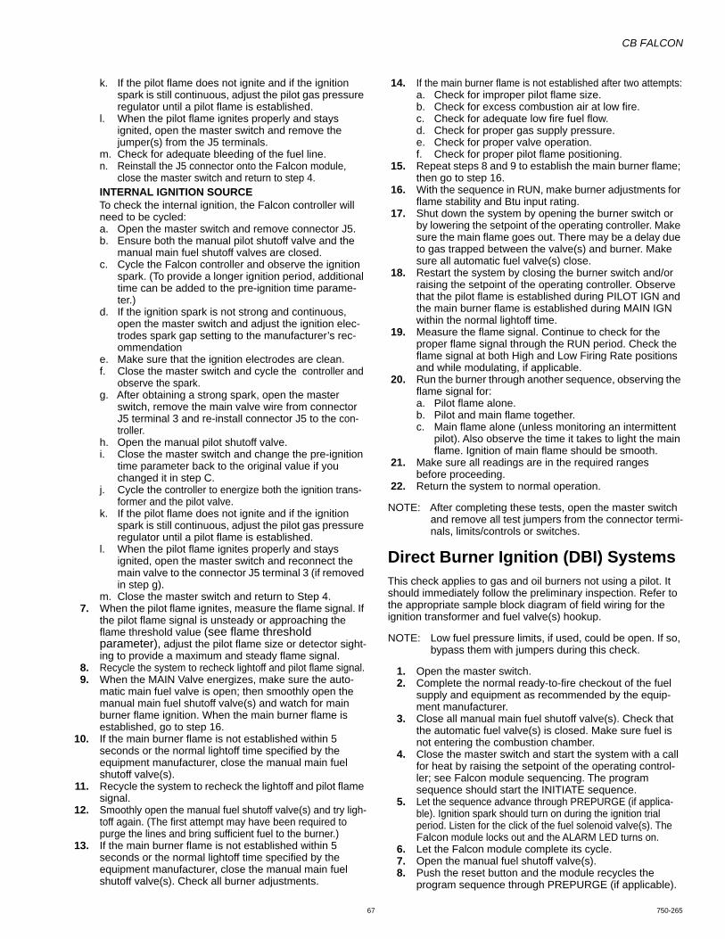
CB FALCON
67 750-265
k. If the pilot flame does not ignite and if the ignition spark is still continuous, adjust the pilot gas pressure regulator until a pilot flame is established.
l. When the pilot flame ignites properly and stays ignited, open the master switch and remove the jumper(s) from the J5 terminals.
m. Check for adequate bleeding of the fuel line.n. Reinstall the J5 connector onto the Falcon module,
close the master switch and return to step 4.INTERNAL IGNITION SOURCETo check the internal ignition, the Falcon controller will need to be cycled:a. Open the master switch and remove connector J5.b. Ensure both the manual pilot shutoff valve and the
manual main fuel shutoff valves are closed.c. Cycle the Falcon controller and observe the ignition
spark. (To provide a longer ignition period, additional time can be added to the pre-ignition time parame-ter.)
d. If the ignition spark is not strong and continuous, open the master switch and adjust the ignition elec-trodes spark gap setting to the manufacturer’s rec-ommendation
e. Make sure that the ignition electrodes are clean. f. Close the master switch and cycle the controller and
observe the spark.g. After obtaining a strong spark, open the master
switch, remove the main valve wire from connector J5 terminal 3 and re-install connector J5 to the con-troller.
h. Open the manual pilot shutoff valve.i. Close the master switch and change the pre-ignition
time parameter back to the original value if you changed it in step C.
j. Cycle the controller to energize both the ignition trans-former and the pilot valve.
k. If the pilot flame does not ignite and if the ignition spark is still continuous, adjust the pilot gas pressure regulator until a pilot flame is established.
l. When the pilot flame ignites properly and stays ignited, open the master switch and reconnect the main valve to the connector J5 terminal 3 (if removed in step g).
m. Close the master switch and return to Step 4.7. When the pilot flame ignites, measure the flame signal. If
the pilot flame signal is unsteady or approaching the flame threshold value (see flame threshold parameter), adjust the pilot flame size or detector sight-ing to provide a maximum and steady flame signal.
8. Recycle the system to recheck lightoff and pilot flame signal.9. When the MAIN Valve energizes, make sure the auto-
matic main fuel valve is open; then smoothly open the manual main fuel shutoff valve(s) and watch for main burner flame ignition. When the main burner flame is established, go to step 16.
10. If the main burner flame is not established within 5 seconds or the normal lightoff time specified by the equipment manufacturer, close the manual main fuel shutoff valve(s).
11. Recycle the system to recheck the lightoff and pilot flame signal.
12. Smoothly open the manual fuel shutoff valve(s) and try ligh-toff again. (The first attempt may have been required to purge the lines and bring sufficient fuel to the burner.)
13. If the main burner flame is not established within 5 seconds or the normal lightoff time specified by the equipment manufacturer, close the manual main fuel shutoff valve(s). Check all burner adjustments.
14. If the main burner flame is not established after two attempts:a. Check for improper pilot flame size.b. Check for excess combustion air at low fire.c. Check for adequate low fire fuel flow.d. Check for proper gas supply pressure.e. Check for proper valve operation.f. Check for proper pilot flame positioning.
15. Repeat steps 8 and 9 to establish the main burner flame; then go to step 16.
16. With the sequence in RUN, make burner adjustments for flame stability and Btu input rating.
17. Shut down the system by opening the burner switch or by lowering the setpoint of the operating controller. Make sure the main flame goes out. There may be a delay due to gas trapped between the valve(s) and burner. Make sure all automatic fuel valve(s) close.
18. Restart the system by closing the burner switch and/or raising the setpoint of the operating controller. Observe that the pilot flame is established during PILOT IGN and the main burner flame is established during MAIN IGN within the normal lightoff time.
19. Measure the flame signal. Continue to check for the proper flame signal through the RUN period. Check the flame signal at both High and Low Firing Rate positions and while modulating, if applicable.
20. Run the burner through another sequence, observing the flame signal for:a. Pilot flame alone.b. Pilot and main flame together.c. Main flame alone (unless monitoring an intermittent
pilot). Also observe the time it takes to light the main flame. Ignition of main flame should be smooth.
21. Make sure all readings are in the required rangesbefore proceeding.
22. Return the system to normal operation.
NOTE: After completing these tests, open the master switch and remove all test jumpers from the connector termi-nals, limits/controls or switches.
Direct Burner Ignition (DBI) SystemsThis check applies to gas and oil burners not using a pilot. It should immediately follow the preliminary inspection. Refer to the appropriate sample block diagram of field wiring for the ignition transformer and fuel valve(s) hookup.
NOTE: Low fuel pressure limits, if used, could be open. If so, bypass them with jumpers during this check.
1. Open the master switch.2. Complete the normal ready-to-fire checkout of the fuel
supply and equipment as recommended by the equip-ment manufacturer.
3. Close all manual main fuel shutoff valve(s). Check that the automatic fuel valve(s) is closed. Make sure fuel is not entering the combustion chamber.
4. Close the master switch and start the system with a call for heat by raising the setpoint of the operating control-ler; see Falcon module sequencing. The program sequence should start the INITIATE sequence.
5. Let the sequence advance through PREPURGE (if applica-ble). Ignition spark should turn on during the ignition trial period. Listen for the click of the fuel solenoid valve(s). The Falcon module locks out and the ALARM LED turns on.
6. Let the Falcon module complete its cycle.7. Open the manual fuel shutoff valve(s).8. Push the reset button and the module recycles the
program sequence through PREPURGE (if applicable).
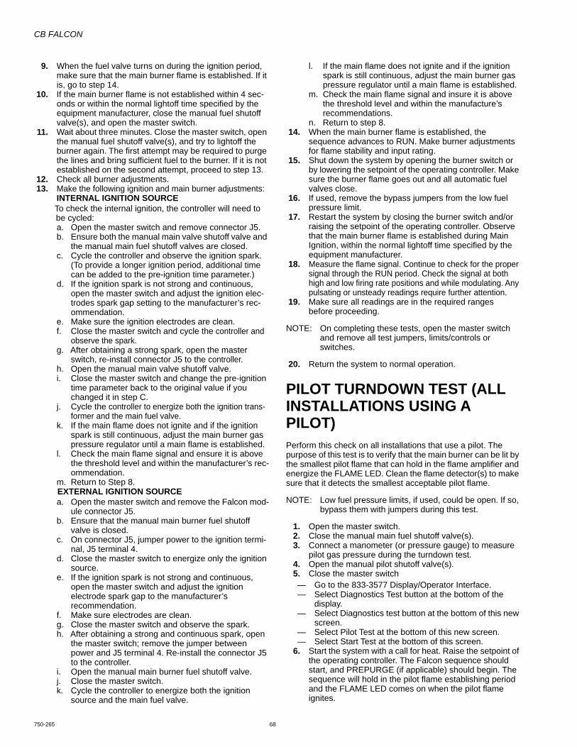
CB FALCON
750-265 68
9. When the fuel valve turns on during the ignition period, make sure that the main burner flame is established. If it is, go to step 14.
10. If the main burner flame is not established within 4 sec-onds or within the normal lightoff time specified by the equipment manufacturer, close the manual fuel shutoff valve(s), and open the master switch.
11. Wait about three minutes. Close the master switch, open the manual fuel shutoff valve(s), and try to lightoff the burner again. The first attempt may be required to purge the lines and bring sufficient fuel to the burner. If it is not established on the second attempt, proceed to step 13.
12. Check all burner adjustments.13. Make the following ignition and main burner adjustments:
INTERNAL IGNITION SOURCETo check the internal ignition, the controller will need to be cycled:a. Open the master switch and remove connector J5.b. Ensure both the manual main valve shutoff valve and
the manual main fuel shutoff valves are closed.c. Cycle the controller and observe the ignition spark.
(To provide a longer ignition period, additional time can be added to the pre-ignition time parameter.)
d. If the ignition spark is not strong and continuous, open the master switch and adjust the ignition elec-trodes spark gap setting to the manufacturer’s rec-ommendation.
e. Make sure the ignition electrodes are clean.f. Close the master switch and cycle the controller and
observe the spark.g. After obtaining a strong spark, open the master
switch, re-install connector J5 to the controller.h. Open the manual main valve shutoff valve.i. Close the master switch and change the pre-ignition
time parameter back to the original value if you changed it in step C.
j. Cycle the controller to energize both the ignition trans-former and the main fuel valve.
k. If the main flame does not ignite and if the ignition spark is still continuous, adjust the main burner gas pressure regulator until a main flame is established.
l. Check the main flame signal and ensure it is above the threshold level and within the manufacturer’s rec-ommendation.
m. Return to Step 8.EXTERNAL IGNITION SOURCE a. Open the master switch and remove the Falcon mod-
ule connector J5.b. Ensure that the manual main burner fuel shutoff
valve is closed.c. On connector J5, jumper power to the ignition termi-
nal, J5 terminal 4.d. Close the master switch to energize only the ignition
source.e. If the ignition spark is not strong and continuous,
open the master switch and adjust the ignition electrode spark gap to the manufacturer’s recommendation.
f. Make sure electrodes are clean.g. Close the master switch and observe the spark.h. After obtaining a strong and continuous spark, open
the master switch; remove the jumper between power and J5 terminal 4. Re-install the connector J5 to the controller.
i. Open the manual main burner fuel shutoff valve.j. Close the master switch.k. Cycle the controller to energize both the ignition
source and the main fuel valve.
l. If the main flame does not ignite and if the ignition spark is still continuous, adjust the main burner gas pressure regulator until a main flame is established.
m. Check the main flame signal and insure it is above the threshold level and within the manufacture’s recommendations.
n. Return to step 8.14. When the main burner flame is established, the
sequence advances to RUN. Make burner adjustments for flame stability and input rating.
15. Shut down the system by opening the burner switch or by lowering the setpoint of the operating controller. Make sure the burner flame goes out and all automatic fuel valves close.
16. If used, remove the bypass jumpers from the low fuelpressure limit.
17. Restart the system by closing the burner switch and/or raising the setpoint of the operating controller. Observe that the main burner flame is established during Main Ignition, within the normal lightoff time specified by the equipment manufacturer.
18. Measure the flame signal. Continue to check for the proper signal through the RUN period. Check the signal at both high and low firing rate positions and while modulating. Any pulsating or unsteady readings require further attention.
19. Make sure all readings are in the required rangesbefore proceeding.
NOTE: On completing these tests, open the master switch and remove all test jumpers, limits/controls or switches.
20. Return the system to normal operation.
PILOT TURNDOWN TEST (ALL INSTALLATIONS USING A PILOT)Perform this check on all installations that use a pilot. The purpose of this test is to verify that the main burner can be lit by the smallest pilot flame that can hold in the flame amplifier and energize the FLAME LED. Clean the flame detector(s) to make sure that it detects the smallest acceptable pilot flame.
NOTE: Low fuel pressure limits, if used, could be open. If so, bypass them with jumpers during this test.
1. Open the master switch. 2. Close the manual main fuel shutoff valve(s). 3. Connect a manometer (or pressure gauge) to measure
pilot gas pressure during the turndown test. 4. Open the manual pilot shutoff valve(s). 5. Close the master switch — Go to the 833-3577 Display/Operator Interface.— Select Diagnostics Test button at the bottom of the
display.— Select Diagnostics test button at the bottom of this new
screen.— Select Pilot Test at the bottom of this new screen.— Select Start Test at the bottom of this screen.
6. Start the system with a call for heat. Raise the setpoint of the operating controller. The Falcon sequence should start, and PREPURGE (if applicable) should begin. The sequence will hold in the pilot flame establishing period and the FLAME LED comes on when the pilot flame ignites.
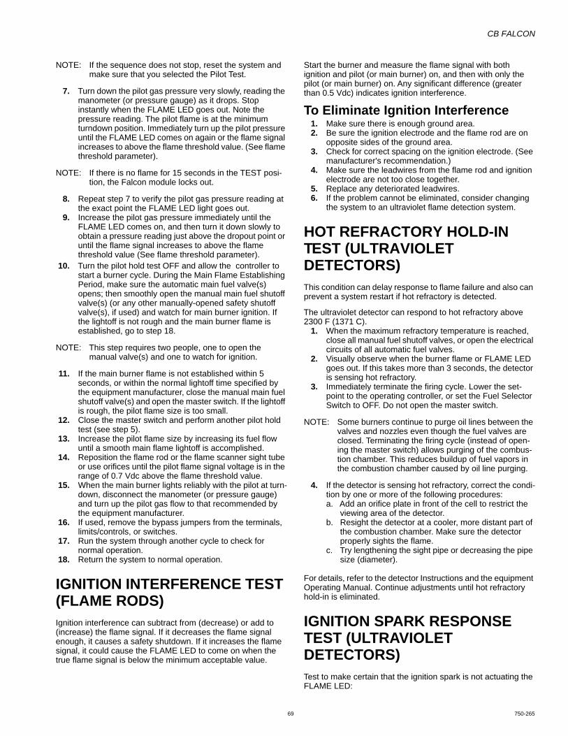
CB FALCON
69 750-265
NOTE: If the sequence does not stop, reset the system and make sure that you selected the Pilot Test.
7. Turn down the pilot gas pressure very slowly, reading the manometer (or pressure gauge) as it drops. Stop instantly when the FLAME LED goes out. Note the pressure reading. The pilot flame is at the minimum turndown position. Immediately turn up the pilot pressure until the FLAME LED comes on again or the flame signal increases to above the flame threshold value. (See flame threshold parameter).
NOTE: If there is no flame for 15 seconds in the TEST posi-tion, the Falcon module locks out.
8. Repeat step 7 to verify the pilot gas pressure reading at the exact point the FLAME LED light goes out.
9. Increase the pilot gas pressure immediately until the FLAME LED comes on, and then turn it down slowly to obtain a pressure reading just above the dropout point or until the flame signal increases to above the flame threshold value (See flame threshold parameter).
10. Turn the pilot hold test OFF and allow the controller to start a burner cycle. During the Main Flame Establishing Period, make sure the automatic main fuel valve(s) opens; then smoothly open the manual main fuel shutoff valve(s) (or any other manually-opened safety shutoff valve(s), if used) and watch for main burner ignition. If the lightoff is not rough and the main burner flame is established, go to step 18.
NOTE: This step requires two people, one to open the manual valve(s) and one to watch for ignition.
11. If the main burner flame is not established within 5 seconds, or within the normal lightoff time specified by the equipment manufacturer, close the manual main fuel shutoff valve(s) and open the master switch. If the lightoff is rough, the pilot flame size is too small.
12. Close the master switch and perform another pilot hold test (see step 5).
13. Increase the pilot flame size by increasing its fuel flow until a smooth main flame lightoff is accomplished.
14. Reposition the flame rod or the flame scanner sight tube or use orifices until the pilot flame signal voltage is in the range of 0.7 Vdc above the flame threshold value.
15. When the main burner lights reliably with the pilot at turn-down, disconnect the manometer (or pressure gauge) and turn up the pilot gas flow to that recommended by the equipment manufacturer.
16. If used, remove the bypass jumpers from the terminals, limits/controls, or switches.
17. Run the system through another cycle to check fornormal operation.
18. Return the system to normal operation.
IGNITION INTERFERENCE TEST (FLAME RODS)Ignition interference can subtract from (decrease) or add to (increase) the flame signal. If it decreases the flame signal enough, it causes a safety shutdown. If it increases the flame signal, it could cause the FLAME LED to come on when the true flame signal is below the minimum acceptable value.
Start the burner and measure the flame signal with both ignition and pilot (or main burner) on, and then with only the pilot (or main burner) on. Any significant difference (greater than 0.5 Vdc) indicates ignition interference.
To Eliminate Ignition Interference 1. Make sure there is enough ground area. 2. Be sure the ignition electrode and the flame rod are on
opposite sides of the ground area. 3. Check for correct spacing on the ignition electrode. (See
manufacturer's recommendation.) 4. Make sure the leadwires from the flame rod and ignition
electrode are not too close together. 5. Replace any deteriorated leadwires. 6. If the problem cannot be eliminated, consider changing
the system to an ultraviolet flame detection system.
HOT REFRACTORY HOLD-IN TEST (ULTRAVIOLET DETECTORS)This condition can delay response to flame failure and also can prevent a system restart if hot refractory is detected.
The ultraviolet detector can respond to hot refractory above 2300 F (1371 C).
1. When the maximum refractory temperature is reached, close all manual fuel shutoff valves, or open the electrical circuits of all automatic fuel valves.
2. Visually observe when the burner flame or FLAME LED goes out. If this takes more than 3 seconds, the detector is sensing hot refractory.
3. Immediately terminate the firing cycle. Lower the set-point to the operating controller, or set the Fuel Selector Switch to OFF. Do not open the master switch.
NOTE: Some burners continue to purge oil lines between the valves and nozzles even though the fuel valves are closed. Terminating the firing cycle (instead of open-ing the master switch) allows purging of the combus-tion chamber. This reduces buildup of fuel vapors in the combustion chamber caused by oil line purging.
4. If the detector is sensing hot refractory, correct the condi-tion by one or more of the following procedures: a. Add an orifice plate in front of the cell to restrict the
viewing area of the detector.b. Resight the detector at a cooler, more distant part of
the combustion chamber. Make sure the detector properly sights the flame.
c. Try lengthening the sight pipe or decreasing the pipe size (diameter).
For details, refer to the detector Instructions and the equipment Operating Manual. Continue adjustments until hot refractory hold-in is eliminated.
IGNITION SPARK RESPONSE TEST (ULTRAVIOLET DETECTORS) Test to make certain that the ignition spark is not actuating the FLAME LED:

CB FALCON
750-265 70
1. Open the master switch.2. Close the pilot and main burner manual fuel shut-off
valve(s).3. Close the master switch — Go to the 833-3577 Display/Operator Interface.— Select Diagnostics Test button at the bottom of the
display.— Select Diagnostics test button at the bottom of this new
screen.— Select Pilot Test at the bottom of this new screen.— Select Start Test at the bottom of this screen.
4. Start the system with a call for heat. Raise the setpoint of the operating controller. The Falcon sequence should start and prepurge (if applicable) should begin. The sequence will hold in pilot flame establishing period with only the ignition on. Ignition spark should occur but the flame signal should not be more than 0.5 Vdc.
5. If the flame signal is higher than 0.5 Vdc and the FLAME LED does come on, consult the equipment operating manual and resight the detector farther out from the spark, or away from possible reflection. It may be neces-sary to construct a barrier to block the ignition spark from the detector view. Continue adjustments until the flame signal due to ignition spark is less than 0.5 Vdc.
NOTE: For controllers with software revision xxxx.2292 or higher, if the above procedures have been attempted and flame signal is still above 0.5 Vdc, use the follow-ing procedure:
FOR DIRECT BURNER IGNITION SYSTEMSa. Using the 833-3577 Display/Operator Interface,
select the Configure button (lower left corner of the Status page).
b. Using the left scroll down function, scroll down to select the System Configuration Parameter page (you will need to be logged in with a password).
c. Select Flame Sensor Type parameter.d. Select UV Power Tube with Spark Interference.e. Changing the Flame Sensor Type will require param-
eter verification.f. Page back one level (upper right screen corner back
arrow button).g. Select the Verify button.h. Select Begin.i. Follow the prompts on the Operator Interface.FOR PILOT SYSTEMSa. Using the 833-3577 Display/Operator Interface,
select the Configure button (lower left corner of the Status page).
b. Using the left scroll down function, scroll down to select the System Configuration Parameter page (you will need to be logged in with a password).
c. Select Flame Sensor Type parameter.d. Select UV Power Tube with Spark Interference.e. Select the Burner Control Ignition Page.f. Select Ignitor On During parameter.g. Select 1st half of PFEP.h. Changing these two parameters will require parame-
ter verification.i. Page back one level (upper right screen corner back
arrow button).j. Select the Verify button.k. Select Begin.l. Follow the prompts on the Operator Interface.
Response to Other Ultraviolet Sources Some sources of artificial light (such as incandescent or fluorescent bulbs, and mercury sodium vapor lamps) and daylight produce small amounts of ultraviolet radiation. Under certain conditions, an ultraviolet detector responds to these sources as if it is sensing a flame. To check for proper detector operation, check the Flame Failure Response Time (FFRT) and conduct Safety Shutdown Tests under all operating conditions.
Flame Signal With Hot Combustion Chamber (All Installations)
1. With all initial start-up tests and burner adjustments com-pleted, operate the burner until the combustion chamber is at the maximum expected temperature.
2. Observe the equipment manufacturer’s warm-up instructions.
3. Recycle the burner under these hot conditions and mea-sure the flame signal. Check the pilot alone, the main burner flame alone, and both together (unless monitoring only the pilot flame when using an intermittent pilot, or only the main burner flame when using DBI). Check the signal at both High and Low Firing Rate positions and while modulating, if applicable.
4. Lower the setpoint of the operating controller and observe the time it takes for the burner flame to go out. This should be within four seconds FFRT of the control-ler.
5. If the flame signal is too low or unsteady, check the flame detector temperature. Relocate the detector if the tem-perature is too high.
6. If necessary, realign the sighting to obtain the proper sig-nal and response time.
7. If the response time is still too slow, replace the control-ler.
8. If the detector is relocated or resighted, or the controller is replaced, repeat all required Checkout tests.
SAFETY SHUTDOWN TESTS (ALL INSTALLATIONS) Perform these tests at the end of Checkout, after all other tests are completed. If used, the external alarm should turn on. Press the RESET pushbutton on the Falcon module to restart the system.
1. Open a Pre-Ignition Interlock (if PII parameter is enabled) during the STANDBY or PREPURGE period.a. *Pre-Ignition ILK* fault is displayed on the Operator
Interface Module.b. Safety shutdown occurs.
2. Opening a Lockout Interlock during PREPURGE, PILOT IGN, MAIN IGN or RUN period.a. *Lockout ILK* fault is displayed on the Operator
Interface Module.b. Safety shutdown occurs.
3. Detection of flame 240 seconds after entry to STANDBY from RUN. Detection of flame from 10 seconds up to 30 sec-onds into PREPURGE time.a. Simulate a flame to cause the flame signal voltage
level to rise above the flame threshold value for 240 seconds after entry to STANDBY from RUN and also

CB FALCON
71 750-265
simulate a flame signal for 10 seconds to 30 seconds for PREPURGE.
b. *Flame Detected out of sequence* fault is displayed on the Operator Interface Module.
c. Safety shutdown occurs.4. Failure to ignite pilot or Main Burner (DBI setup).
a. Close pilot and main fuel manual shutoff valve(s). b. Cycle burner on. c. Automatic pilot valve(s) or main valves (DBI) should
be energized but the pilot or main burner (DBI) can-not ignite.
d. *Ignition Failure* fault is displayed on the Operator Interface to indicate the fault.
e. Safety shutdown occurs.5. Failure to ignite main (only interrupted pilot application).
a. Open the manual pilot valve(s); leave the main fuel manual shutoff valve(s) closed.
b. Depress the RESET button.c. Start the system.d. The pilot should ignite and the flame signal should be
above the flame threshold value but the main burner cannot light.
e. The flame signal should drop below the flame thresh-old value within the FFRT after the interrupted pilot goes out.
f. *Ignition Failure* fault is displayed on the Operator Interface Module.
g. Safety shutdown occurs.6. Loss of flame during RUN.
a. Open the main fuel manual shutoff valve(s) and open manual pilot shutoff valve(s).
b. Depress the RESET button.c. Start the system. Start-up should be normal and the
main burner should light normally.d. After the sequence is in the normal RUN period for at
least 10 seconds with the main burner firing, close the manual main fuel shutoff valve(s) to extinguish the main burner flame. (On intermittent pilot applications, also, close the pilot manual shutoff valve.)
e. The flame signal should drop below the flame thresh-old value within the FFRT of the Falcon module after the main flame and/or pilot goes out.
f. *Main Flame Fail* fault is displayed on the Operator Interface Module.
g. Safety shutdown or recycle, then lock out on failure to light the pilot depending on the configuration the Fal-con module.
7. Open a Pre-Ignition Interlock after the first 5seconds of POSTPURGE.a. Open the main fuel manual shutoff valve(s) and open
manual pilot shutoff valve(s).b. Depress the RESET button.c. *Pre-Ignition ILK* fault is displayed on the Operator
Interface Module. d. Safety shutdown occurs.
IMPORTANTIf the Falcon module fails to shut down on any of these tests, take corrective action; refer to Trouble-shooting and the Falcon module diagnostics and return to the beginning of all checkout tests.
When all checkout tests are completed, reset all switches to the original status. Remove any jumpers that you may have installed for testing.
TROUBLESHOOTINGSystem Diagnostics Troubleshooting control system equipment failures is easier with the Falcon’s self-diagnostics and first-out annunciation. In addition to an isolated spst alarm relay (audible annunciation), the Falcon module provides visual annunciation by displaying a fault code and fault or hold message at the 833-3577 Display/Operator Interface. The Falcon modules provide many diagnostic and alert messages for troubleshooting the system.
Self-diagnostics of the Falcon modules enables them to detect and annunciate both external and internal system problems. Fault messages, such as interlock failures, flame failures and false flame signals are displayed at the Operator Interface Module and annunciated at the Falcon by the ALARM LED.
The Operator Interface displays a sequence status message indicating: STANDBY, PURGE, PILOT IGN, MAIN IGN, RUN and POSTPURGE. The selectable messages also provide visual indication of current status and historical status of the equipment such as: Flame Signal, Total Cycles, Total Hours, Fault History, Diagnostic Information and Expanded Annunciator terminal status (if used). With this information, most problems can be diagnosed without extensive trial and error testing.
Diagnostic Information Lockout and Alert History Data are available to assist in troubleshooting the Falcon module.
The module provides diagnostic information to aid the service mechanic in obtaining information when trouble-shooting the system.
Diagnostic Information IndexThe Falcon modules monitor digital and analog input/output (I/O) terminals and can display the status of the terminal at the Operator Interface Module. The display shows the actual status of the terminal. If voltage is detected at a digital I/O terminal, the LED turns green next to the terminal energized, but if no voltage is detected at the terminal, the LED will be red. Actual analog I/O values are displayed on the operator interface module.
Historical Information IndexThe Falcon modules have nonvolatile memory that allows them to retain historical information for the fifteen most recent lockouts. Each of the fifteen lockout files retains the cycle when the fault occurred, the hour of operation when the fault occurred, a fault code, a fault message and burner status when the fault occurred. In addition to the lockout files, the Falcon modules retain fifteen alert files.
SERVICE NOTES:1. Reset the device module by pressing the RESET push-
button on the device or pressing a remote reset pushbut-ton wired into connector J10 or through the display. A power-up reset causes an electrical reset of the module but does not reset a lockout condition.
2. Use the connector screw terminals to check input or out-put voltage.

CB FALCON
750-265 72
LEAD LAGFalcon devices contain the ability to be a stand-alone control, operate as a Lead Lag Master control (which also uses the Falcon control function as one of the slaves), or to operate solely as a slave to the lead lag system.
Falcon devices utilize two Modbus ports (MB1 and MB2) for communications. One port is designated to support a system display and the other port supports communications from the LL Master with its slaves. Fig. 28 shows a simplified wiring diagram connecting the system display with a 4 system Lead Lag arrangement.
The Lead Lag master is a software service that is hosted by a Falcon control. It is not a part of that control, but is an entity that is “above” all of the individual Falcon controls (including the one that hosts it). The Lead Lag master sees the controls as a set of Modbus devices, each having certain registers, and in this regard it is entirely a communications bus device, talking to the slave Falcon controls via Modbus.
The LL master uses a few of the host Falcon's sensors (header temperature and outdoor temperature) and also the STAT electrical inputs in a configurable way, to provide control information.
Lead Lag (LL) Master General OperationThe LL master coordinates the firing of its slave units. To do this it adds and drops stages to meet changes in load, and it sends firing rate commands to those that are firing.
The LL master turns the first stage on and eventually turns the last stage off using the same criteria as for any modulation control loop:• When the operating point reaches the Setpoint minus the
On hysteresis, then the first Falcon is turned on.• When the operating point reaches the Setpoint plus the Off
hysteresis then the last slave Falcon (or all slave units) are turned off.
The LL master PID operates using a percent rate: 0% is a request for no heat at all, and 100% means firing at the maximum modulation rate.
The LL master may be aware of slave’s minimum firing rate and use this information for some of its algorithms, but when apportioning rate it may also assign rates that are less than this. In fact, the add-stage and drop-stage algorithms may assume this and be defined in terms of theoretical rates that are possibly lower than the actual minimum rate of the Falcon control. A unit that is firing and is being commanded to fire at less than its minimum modulation rate will operate at its minimum rate: this is a standard behavior for a Falcon control in stand-alone (non-slave) mode.
If any slave under LL Master control is in a Run-Limited condition, then for some algorithms the LL master can apportion to that stage the rate that it is actually firing at.
Additionally when a slave imposes its own Run-limited rate, this may trigger the LL Master to add a stage, if it needs more capacity, or drop a stage if the run-limiting is providing too much heat (for example if a stage is running at a higher-than commanded rate due to anti-condensation).
By adjusting the parameters in an extreme way it is possible to define add-stage and drop-stage conditions that overlap or even cross over each other. Certainly it is incorrect to do this, and it would take a very deliberate and non-accidental act to accomplish it. But there are two points in this:
1. LL master does not prevent it, and more important;2. it will not confuse the LL master because it is imple-
mented as a state machine that is in only one state at a time;
for example:— if its add-stage action has been triggered, it will remain
in this condition until either a stage has been added,or
— the criteria for its being in an add-stage condition is no longer met; only then will it take another look around to see what state it should go to next.
AssumptionsModulating stage The modulating stage is the Falcon that is receiving varying firing rate requests to track the load.
First stage This is the Falcon that was turned on first, when no slaves were firing.
Previous stage The Falcon that was added to those stages that are firing Just prior to the adding of the Falcon that is under discussion.
Next stage The Falcon that will or might be added as the next one to fire.
Last stage The Falcon that is firing and that was added the most recently to the group of slaves that are firing. Typically this is also the modulating stage, however as the load decreases then the last-added stage will be at its minimum rate and the previous stage will be modulating.
Lead boiler The Lead boiler is the Falcon that is the first stage to fire among those stages which are in the equalize runtime (Lead/Lag) group. If a boiler is in the “Use first” group it may fire before the Lead boiler fires.
First boiler A Falcon may be assigned to any of three groups: “Use First”, “Equalize Runtime”, or “Use Last”. If one or more Falcons are in the “Use First” category, then one of these (the one with the lowest sequence number) will always be the first boiler to fire. If there is no Falcon in the “Use First” category and one or more are in the “Equalize Runtime” category, then the First boiler is also the Lead boiler.

CB FALCON
73 750-265
Add-stage method, Add-stage detection timing, Add-stage requestAn Add-stage method implements the criteria for adding another stage. Criteria that may apply are the firing rate of a stage or stages vs. a threshold, the amount of operating point versus setpoint error seen by the master, the rate at which setpoint error is developing, and the rate at which a stage or stages are approaching their maximum or baseload firing rate.
Typically these use Add-stage detection timing to determine how long these things have persisted. When all criteria have been met for a sufficient time, then an Addstage request is active.
Drop-stage method, Drop-stage detection timing, Drop-stage requestA Drop-stage method implements the criteria for dropping a stage. Criteria that may apply are the firing rate of a stage (or stages) vs. a threshold, the amount of operating point versus setpoint error seen by the master, the rate at which setpoint error is developing, and the rate at which a stage or stages are approaching their minimum firing rate. Typically these use Drop-stage detection timing to determine how long these things have persisted. When all criteria have been met for a sufficient time, then an Drop-stage request is active.
Fig. 28. Lead lag wiring diagram.
21 4 5 6 7 8 93
+12 (B) (A) N/CGND (C)+12 N/C (A) (B)
DISPLAY
COM1 COM2L1
L2
120VAC
VADJ
V+
N
L
V-DC OUT(COMMON GND)
12 DC OUT +
EARTHGROUND
120VAC (L1)
NEUTRAL (L2)
MEAN WELL S-25-12
DO NOT CONNECT THE DISPLAY TO TERMINALS 1 2 3.THIS WILL RENDER THE DISPLAY INOPERABLE.
DISPLAY CAN ALSO BE CONNECTED TO MB2; A, B, C.
FALCON HAS TWO AVAILABLE MODBUS CONNECTIONS: THIS CONFIGURATION REQUIRES ONE FOR LEAD LAG COMMUNICATION AND ONE FOR A SYSTEM DISPLAY.
THERE IS NOT A CONNECTION AVAILABLE FOR A LOCAL TOUCHSCREEN DISPLAY.
POWER SUPPLY
WIRING KEY
LOW VOLTAGEDATA
LINE VOLTAGE LL MASTER
AND SLAVE 1
2 3C B A C B1A
J3MB1 ECOMMB2
2 3C B A C B1A
SLAVE 2
J3MB1 ECOMMB2
2 3C B A C B1A
SLAVE 3
J3MB1 ECOMMB2
2 3C B A C B1A
SLAVE 4
J3MB1 ECOMMB2
1
1
2
3
3
2

CB FALCON
750-265 74
Lead-Lag OperationOEM Configurable parameters may be adjusted as part of the OEM factory configuration and in the field using the System Display with appropriate password permissions (see “Passwords” on page 18). Specific parameters may also be configured in the field by the local display.
Field Installation Configuration1. The master and slave controllers are enabled via the
system display.2. All Falcon controllers are programmed with a default
address of 1.Assuming the Master Falcon controller remains address 1, the address of the slave controllers in the system must have a unique address (1–8) via the local display.
Basic Operation1. Firing rate determination – Parallel common-base limited
a. All boilers have a single assignable base load firing rate.
b. Allocation(1) As load increases:
(a)Until all stages are firing - No stage is requested to exceed the common base load rate.
(b)After all stages are firing - There is no restric-tion on the slave's commanded firing rate.
(2) As load decreases:(a)As long as all available stages are firing -
There is no restriction on the slave's com-manded firing rate.
(b)When at least one stage has been dropped - No stage is requested to exceed the common base load rate.
2. Rotationa. The lead boiler is rotated based sequence order. The
lead boiler rotation time is a configurable OEM parameter. Rotation is sequential by address (1-2-3-4; 2-3-4-1; etc.).
b. Rotation trigger occurs at the start of each new heat cycle.
3. Source of heat for call – The call for heat originates at the master boiler. This source can be configured to be an external thermostat or via EnviraCOM Remote Stat.
4. Slave boiler lockout – If any slave is in lockout the mas-ter boiler will cause it to be skipped and all system load setting calculation settings will be based only on avail-able boilers.
5. Master boiler lockout – If the master boiler is in lock-out then its burner control function will be skipped in the rota-tion the same as the slave controllers. However, the master boiler function will continue to operate.
System Component Failure Responses1. If the system header sensor becomes disconnected from
the master boiler then the master boiler will control off of one of the following OEM configurable actionsa. Disable - No backup will be used.b. Lead Outlet - Outlet temperature of the lead boiler
will be used as the backup during firing.c. Slave Outlet Average - Average of the outlet temper-
atures of all slave boilers that are firing will be used as a backup.
2. If the sensor chosen by the above parameter is faulty then the backup sensor provided may be used. When burner demand is off and no burners are firing, then, for
either “Lead Outlet” or “Slave Outlet Average”, the lead boiler's outlet temperature is used to monitor for burner demand.
Local Display Configuration and Operation1. The configuration parameters available on the local dis-
play are edited in the Service Mode.2. Access to the Service Mode is accomplished by pressing
both up/down buttons for 3 seconds.3. Status and Operation
a. Slave status(1) “Rmt” and “Adr” icons are on to show slave (fol-
lower) has been enabled.(2) Current burner status is shown.(3) To show slave CFH.
(a)Alternate “%” firing rate and actual (slave) Out-let temp to indicate slave CFH otherwise show the Home screen.
b. Master status(1) Rmt icon is on, Adr icon is off to show Master
(Leader) has been enabled.(2) Current burner status is shown.(3) Actual temperature LL (Header) temperature is
shown as described in number 5 on page 75 below.
(4) Pressing the up/down buttons allows setpoint adjustment for LL-CH only (not LL-DHW or LL-Mix or others).(a)All pump configurations must be done using
the PC Configuration tool in the OEM factories.(5) To show Master CFH
(a)Alternate “CH” or “LL” or “Hdr” in numbers field with the actual temperature to indicate LL CH CFH.
4. Configurationa. Continue scrolling through set-up screens until
“Remote Firing Control” screen is reached.b. Rmt On/Off selection chooses to navigate the user
through the Master/Slave configuration as existing today.
c. Set master/slave remote address as is done on cur-rently on the local display.
d. The following parameters are mapped to Modbus addresses.(1) “LL” = LL Operation (3 user selections available)
(a)“Ldr”• Master Enable• Slave Enable
(b)“SLA”• Slave Only Enable• Master Disable
(c)“OFF”• Master Disable• Slave Disable
(2) HS = On/Off Hysteresis (One value used for all LL boilers)(a)“HS” for on and off hysteresis values.
• Only allow 1 setting for both on and off hysteresis values.
• Must adhere to the strictest of either the HS On or Off limits:Highest value of the “low” range limit in Falcon controlLowest value of the “high” range limit in Falcon control

CB FALCON
75 750-265
• See Falcon Modbus specification for details.Typical values: 2-15
(3) BL = Baseload common(a)“BL” for baseload(b)User selection 0 – 100 %
(4) Use existing timeout, Done button, and Next but-ton functionality to enter these parameters.
(5) User selections will be selected by MMI.(a)The local display does not adhere to the PCB
(OEM parameter selections used by system display).
5. In normal display operation the display allows a user to scroll through a list of temperatures with associated icons (CH, Inlet, Delta, DHW, Stack, Outdoor) using the Next button. With LL active the display will show the header temperature at the end of the list of temperatures as follows:a. The characters “LL” are displayed in the number
field.b. When the next button is pressed again the tempera-
ture is displayed.c. If the Up or Down buttons are pressed then the LL
set-point is changed.
System Display ConfigurationThe following parameters are available for OEM configuration and may be adjusted through a System Display or programmed at the OEM production facility.
Slave Operation and Setup
Slave Data Supporting Lead LagThis data is provided by each slave control to support operation when a LL master exists. Fig. 29 summarizes the slave's registers and data:
Table 33. OEM Configuration Parameters
Master Falcon Slave FalconLL frost protection enable Slave modeLL frost protection rate Base load rateBase load rate Slave sequence orderLL CH demand switch LL Demand to firing delayLL CH set point sourceLL Modulation sensorLL Base load commonLL Modulation backup sensorLL CH 4mA water temperatureLL Lead selection methodLL CH 20mA water temperatureLL Lag selection methodLL Add stage method 1LL Add stage detection time 1LL Add stage error thresholdLL Add stage rate offsetLL Add stage inter-stage delayLL Drop stage method 1LL Drop stage detection time 1LL Drop stage error thresholdLL Drop stage rate offsetLL Lead rotation timeLL Force lead rotation timeLL Drop stage inter-stage delay

CB FALCON
750-265 76
Fig. 29. Master/Slave data transmission.
Table 34. Slave Data Supporting Lead Lag Parameters.
Parameter CommentLL - Slave enable Disable, Enable via Modbus, Enable for Master
It enables or disables the “LL Slave” Demand and Rate module.
If the slave mode is set to Disable then:none of the slave functions are active, LL - Slave Status register is zero, the LL – Master Service Status register is not writable and is held at zero (this is important for pump control which might otherwise use values in this location).The LL - Slave Command register is writable but it is mostly ignored, however the Aux pump X, Y, and Z are effective for any setting of the LL - Slave enable parameter.The Enable for Falcon Master option LL - Slave write and LL - Slave read parameters; if “Enable for Master” is not selected, then these parameters are disabled.
LL - Slave write dataThis allows the slave to accept command messages from a master.
LL - Slave read dataThis provides the slave status message to be read by a Master. It includes all of the data that is read from a slave.
LL - Slave mode Use First, Equalize Runtime, Use LastIf set to Use First, then this slave will be used prior to using other slave units with other values.If this parameter is set to Equalize Runtime, then this slave will be staged according to a run time equalization. (Any units set to Use First will precede any that are set to Equalize Runtime.)If this parameter is set to Use Last, then this slave will be used only after all Use First and Equalize Runtime units have been brought online.
MASTER
EnviraCO
MIN
PUTS
SLAVE DATA
OUTDOOR
S2 4-20mA
S5
SE
NS
OR
S
STAT
READ BY DISPLAY
STAT2
TOD
OUTDOOR TEMPERATURE
OUTLET TEMPERATURE
SLAVE STATUS
SLAVE ACKNOWLEDGE
SLAVES HAVE DEMAND
DEMANDSUSPENDFIRING RATEOFF CYCLE FANPUMP X, Y, AND Z
MASTER’S HEAT DEMAND
MASTER’S ACTIVE SERVICE
CH CH FROSTDHWDHWFROST
CHNONE
TOPUMPCONTROL
TO BURNER CONTROL
TO FAN CONTROL
FROST WWSD
SLAVES ARE FIRING
SLAVE HAS PRIORITYSLAVE IS MODULATINGCH FROST PROTECTION REQUESTDHW FROST PROTECTION REQUESTFROST PROTECTION BURNER REQUEST
BURNER CONTROL STATUSFIRING FOR LOCAL FROST PROTECTION
STATUS
NOT A SEPARATEREGISTER
TERMINALS
“pRATE” = 0 TO 99.99% OF CAPACITYTIMEOUT: OLD DATA WILL EXPIRET
INPUT OUTPUTPARAMETER
DATA ITEM
LEAD LAG ModBus MESSAGE
MINIMUM MODULATION pRATE
MASTER STATUS
BURNER RUN TIME
SLAVE COMPATIBILITY
MODULATION pRATE
MASTER SERVICE STATUS
MASTER COMPATIBILITY
SLAVECONTROLWRITE
SLAVECONTROLREAD
MASTERSTATUSBROADCAST
SLAVE DATAPOLL READ
BASE LOAD pRATE
SLAVE MBH CAPACITY
SLAVE SEQUENCE ORDER
SLAVE MODE
SLAVE ENABLE
SLAVE COMMAND
DEMAND-TO-FIRING DELAY
T
SLAVE DATA PO
LL (0X2401)SLAVE C
ON
TPOL (0X2400)

CB FALCON
77 750-265
LL Master Operation and SetupLL master operation is subdivided into the following functions:
Overall control - The LL master has parameters that enable and disable its operation.
Periodic data polling - The LL master uses polling to discover new slave Falcon devices and to periodically refresh the information it has about known slave devices.
Slave control - The LL master sends each active slave a command and also performs a slave status read for each known slave device at a high rate. It also sends a Master status broadcast that is heard by all slaves.
Slave status manager - The LL master operates a state machine that keeps track of slave status for each Falcon that is enabled as a slave device.
Demand and priority - Different sources of demand can cause the LL master to operate in different ways. These sources have a priority relationship.
Rate control - Each demand source has one or more setpoints that may be active and an operation sensor. These are used to detect turn-on and turn-off conditions. The difference between operating point and setpoint is sent to a PID block to determines the LL master's firing rate.
Rate allocation - The PID block's output is used to determine the firing rate of each slave using various rate allocation techniques.
Stager - The stager determines when slaves should turn on as the need for heat increases, and when they should turn off as it decreases.
Add-stage methods - Various methods can be used to determine when a new stage should be added.
Drop-stage methods - Various methods can be used to determine when a stage should be dropped
Sequencer - The sequencer determines which Falcon will be the next one to turn on or turn off.
LL - Slave priority sequence order 0-255Slave sequence order is used to determine the order in which the slaves will be used (staged on) for those Falcons with the same Slave mode setting. Numbers may be skipped, that is 3 will be first if there is no 1 or 2.
Note: For Equalize Runtime purposes, 1 does not mean the unit will be used first every time; that will vary over time based on the master's run time equalization scheme. In this case the sequence number determines the relative order in which Falcon controls will be used in a round-robin scheme.If the slave sequence number value is zero, then the slave unit's modbus address will be used instead.If two Falcons are set to the same mode and both have the same sequence number then an alert will occur and the order in which they are used will be arbitrary and is not guaranteed to be repeatable.
LL - Demand-to-firing delay mm:ss or NoneThis delay time is needed by the LL master to determine the length of time to wait between requesting a slave to fire and detecting that it has failed to start. It should be set to the total time normally needed for the burner to transition from Standby to Run, including such things as transition to purge rate, prepurge time, transition to lightoff rate, all ignition timings, and include some extra margin.
LL - Base load rate rpm or %This specifies the preferred firing rate of a burner, which is used for some types of control.
LL - Fan during off-cycle rate rpm or % (0=disable)This determines if or where the fan is to be operating during the standby period.
Table 34. Slave Data Supporting Lead Lag Parameters. (Continued)
Parameter Comment
Table 35. Overall Control Parameters.
Parameter CommentLL master enable Disable, EnableLL master Modbus port MB1, MB2
The LL master may be disabled, enabled. If Disable is selected then all LL master functions are inactive. If Enable is selected then it acts as the active bus master at all times on the modbus port it is assigned to use by the LL Master Modbus port parameter.
LL operation switch Off, OnThis controls the LL master in the same way that the Burner switch controls a stand-alone Falcon. If “On” then the LL master is enabled to operate. If this parameter is “Off” then the LL master turns off all slaves and enters an idle condition.

CB FALCON
750-265 78
Periodic Data Polling MessagesThe LL master will poll to discover all the slave devices when it starts up. Thereafter it polls the known devices to make sure they are still present and to obtain updated status information. It also periodically polls the entire slave address range to discover any new slave devices.
A polled slave unit is read to determine the values of the following data items:
a. The slave's type (compatibility) as indicated by the LL - Slave type
b. The slave enable status LL - Slave enablec. The slave mode as set in LL - Slave moded. The slave sequence order as set in LL - Slave
sequence ordere. LL - Demand-to-firing delay: mm:ss or None
See Table 37.f. CT - Burner run time. See Table 37.
Slave Control MessagesAfter a slave device has been discovered, the LL master sends each slave unit a command message.
There are 5 commands that might be sent:
• DnFnM0: Demand=no, Run off-cycle fan=no, Modulation=0%.The LL master sends this message to all LL slaves when none of these are firing. All slaves are commanded to turn off and remain off.
• DnFyM0: Demand=no, Run off-cycle fan=yes, Modulation=0%.The LL master sends this message to slaves that are off, whenever any slave is firing (due to either LL master control or independent operation).
• DsFnM0 or DsFyM0: Demand=suspend, Run off-cycle fan=y/n, Modulation=0%The LL master sends this message to request a burner to recycle and remain in Standby if it has not yet opened its main valve (e.g. it is in Prepurge or PFEP) but to keep firing if it has reached MFEP or Run.
This message is used to abort the startup of a slave that is not yet firing (because demand went away just before it was firing), but to keep it on if it actually is firing (the LL master will discover what happened in a subsequent status response).
The LL master also sends this message to a slave that is OnLeave. (This ensures that if the slave is firing when it returns to LL master control, it will stay that way until the master has decided whether to use it; or conversely, if the slave stops firing for some reason that it will not start up again until the LL master has requested this.
In either case, the command will be DsFyM0 to turn on the off cycle fan if any other slave burners are firing, or DsFnM0 to turn the fan off if the slave is the only slave that might (or might not) be firing.
• DyFnM0-100: Demand=yes, Run off-cycle fan=no, Modulation=0-100%The LL master sends this message to turn the burner on and to assign the burner’s firing rate.
If the commanded modulation rate is less than the burner’s minimum modulation rate, then the burner should always operate at its minimum rate.
SlaveState StatesRecovering A slave that is recovering is checked once per second. If any of the following are true:DataPollFaultCounter non-zeroStatusReadFaultCounter non-zeroAbnormalFaultCounter non-zero
then the slave's RecoveryTimer is cleared (it has not yet begun to recover). If the RecoveryTimer reaches the RecoveryTime then the slave has recovered and the SlaveState is changed to Available. Each time it is checked (once per second) the slave's RecoveryLimitTimer is also incremented and if the slave has not yet recovered when this timer reaches the RecoveryTimeLimit then:
If the slave is not enabled for the LL master or if its DataPollFaultCounter or StatusReadFaultCounter is non-zero, its SlaveState is Set to Unknown (which logically removes it from the slave table). Otherwise the RecoveryLimitTimer is cleared which starts a new recovery measurement and the slave remains in recovery (indefinitely).
Available A slave in the Available state remains that way until the Stager moves it into the AddStage state or the ProcessSlaveStatus action moves it to some other state.
AddStage A slave in the AddStage state remains that way until the ProcessSlaveStatus moves it to Firing or some other state, or the Stager times out and moves it into the Recovering state if it fails to fire.
SuspendStage A slave in the SuspendStage state remains that way until the ProcessSlaveStatus moves it to some other state, or the Stager times out and moves it into either the Firing or the Available state.
Firing A slave in the Firing state remains that way until the ProcessSlaveStatus moves it to some other state, or the Stager drops the stage and moves it into the Available state.
Table 36. Data Polling Parameters.
Parameter CommentLL - Demand-to-firing delay mm:ss or None
This delay time is needed by the LL master to determine the length of time to wait between requesting a slave to fire and detecting that it has failed to start. It should be set to the total time normally needed for the burner to transition from Standby to Run, including such things as transition to purge rate, prepurge time, transition to lightoff rate, all ignition timings, and some extra margin.
CT - Burner run This parameter will be needed if measured run-time equalization is being used.

CB FALCON
79 750-265
OnLeave A slave in the OnLeave state remains that way until the ProcessSlaveStatus moves it to some other state.
Disabled A slave in the Disabled state remains that way until the ProcessSlaveStatus moves it to Recovering.
Demand and Priority
Fig. 30. LL Master demand sources.
CH DEMAND
WARM WEATHER SHUTDOWN (WW-SD)
LL MASTER DEMAND SOURCES
CENTRAL HEAT
LL CH DEMAND SWITCH
FROST PROTECTION
WARM WEATHER SHUTDOWN
LL WARM WEATHER SHUTDOWN ENABLE
LL WARM WEATHER SHUTDOWN SETPOINT
LL MASTER FROST PROTECT ENABLE
DISABLE LL CHSTATEnviraCOM REMOTE STAT
MASTERHEAT DEMANDS
THE SOURCES ASKINGFOR HEAT. USED FOR
PUMP CONTROL.
MASTERACTIVE SERVICE
THE DEMAND SOURCETHAT IS CURRENTLY
CONTROLLING THE LLMASTER.
Table 37. CH Demand Parameters.
Parameter CommentLL CH demand switch Disable, STAT, EnviraCOM Remote Stat
The inputs that can function as the CH demand switch are: STAT, EnvironCOM Remote Stat. If the CH demand switch value is Disable, the LL master does not respond to CH demand.
Table 38. Warm Weather Shutdown (WW-SD) Parameters.
Parameter CommentWarm weather shutdown enable Disable, Shutdown after demands have ended, Shutdown immediately

CB FALCON
750-265 80
Frost ProtectionLL master frost protection is enabled with the LL - Frost protection enable parameter.
The need for frost protection is actually detected independently by each slave, which notifies the master whether frost detection occurred in CH frost detection, and/or its DHW frost detection, and whether it is severe enough to require burner firing as well as pump operation. This is done via its BC - Slave status parameter.
If LL - Frost protection enable is Enable, then the master's LL - Slave write message, will indicate CH or DHW frost protection or both as read from each slave's BC - Slave Status. This will cause any slave pumps which are enabled to follow this status to turn on without any other action required from the master.
If any slave is indicating CH or DHW frost protection, and additionally that slave's BC - Slave status register indicates burner firing is requested then the LL master's frost protection burner demand will be true.
If the priority scheme allows the master to honor this demand, then it will fire a single burner (the current lead burner as specified by the sequencer) at the rate indicated by LL - Frost protection rate: 0-100%. (100% represents 100% firing of this boiler, and where 0% or any value less than the boiler's minimum firing rate represents the minimum firing rate).
Warm weather shutdown setpoint Temperature or NoneWhen warm weather shutdown is Disabled then it has no effect (i.e. the Warm Weather Shutdown (WW-SD)) status shown on the priority diagram is false).
These two parameters are shared by the stand-alone Falcon control and the LL master and have the same effect for either control.
If it is enabled then it uses a 4°F (2.2°C) hysteresis:
If WW-SD) is false, then when the Outdoor temperature is above the value provided by Warm weather shutdown setpoint then:
If Shutdown after demands have ended is selected then any current CH demand that is present prevents WW-SD) from becoming true; that is if CH demand is false then WW-SD) becomes true.
Otherwise if Shutdown immediately is selected then WW-SD) becomes true, it immediately causes CH demand to end.
If WW-SD) is true, then when the Outdoor temperature is below the value provided by Warm weather shutdown setpoint minus 4°F then WW-SD) becomes false.
When warm weather shutdown is true then:New occurrences of CH demand is inhibited.DHW demand is not affected.
Table 38. Warm Weather Shutdown (WW-SD) Parameters. (Continued)
Parameter Comment
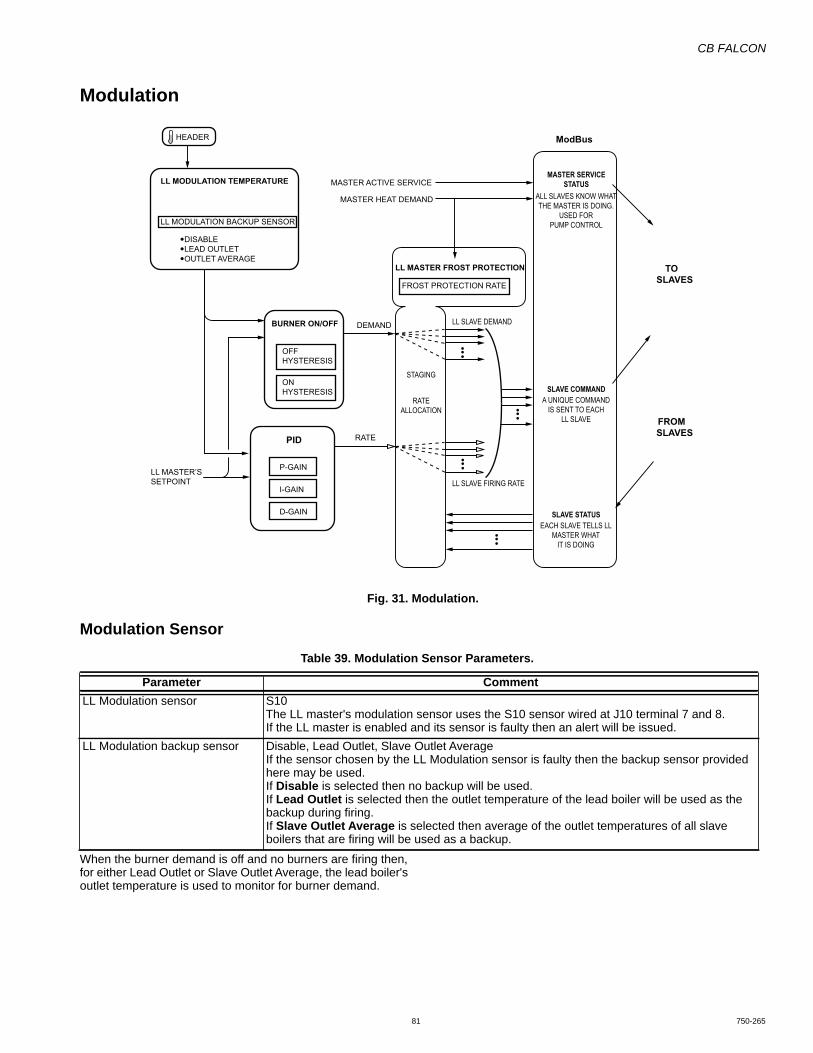
CB FALCON
81 750-265
Modulation
Fig. 31. Modulation.
Modulation Sensor
When the burner demand is off and no burners are firing then, for either Lead Outlet or Slave Outlet Average, the lead boiler's outlet temperature is used to monitor for burner demand.
HEADER
LL MODULATION TEMPERATURE
BURNER ON/OFF
PID
ModBus
LL MASTER’SSETPOINT
OFFHYSTERESIS
P-GAIN
DEMAND
MASTER ACTIVE SERVICE
MASTER HEAT DEMAND
FROST PROTECTION RATE
LL MASTER FROST PROTECTION TOSLAVES
FROMSLAVESRATE
LL SLAVE FIRING RATE
LL SLAVE DEMAND
RATEALLOCATION
STAGING
MASTER SERVICESTATUS
ALL SLAVES KNOW WHATTHE MASTER IS DOING.
USED FORPUMP CONTROL
SLAVE COMMANDA UNIQUE COMMAND
IS SENT TO EACHLL SLAVE
SLAVE STATUSEACH SLAVE TELLS LL
MASTER WHATIT IS DOING
LL MODULATION BACKUP SENSOR
DISABLELEAD OUTLETOUTLET AVERAGE
ONHYSTERESIS
I-GAIN
D-GAIN
Table 39. Modulation Sensor Parameters.
Parameter CommentLL Modulation sensor S10
The LL master's modulation sensor uses the S10 sensor wired at J10 terminal 7 and 8.If the LL master is enabled and its sensor is faulty then an alert will be issued.
LL Modulation backup sensor Disable, Lead Outlet, Slave Outlet AverageIf the sensor chosen by the LL Modulation sensor is faulty then the backup sensor provided here may be used.If Disable is selected then no backup will be used.If Lead Outlet is selected then the outlet temperature of the lead boiler will be used as the backup during firing.If Slave Outlet Average is selected then average of the outlet temperatures of all slave boilers that are firing will be used as a backup.
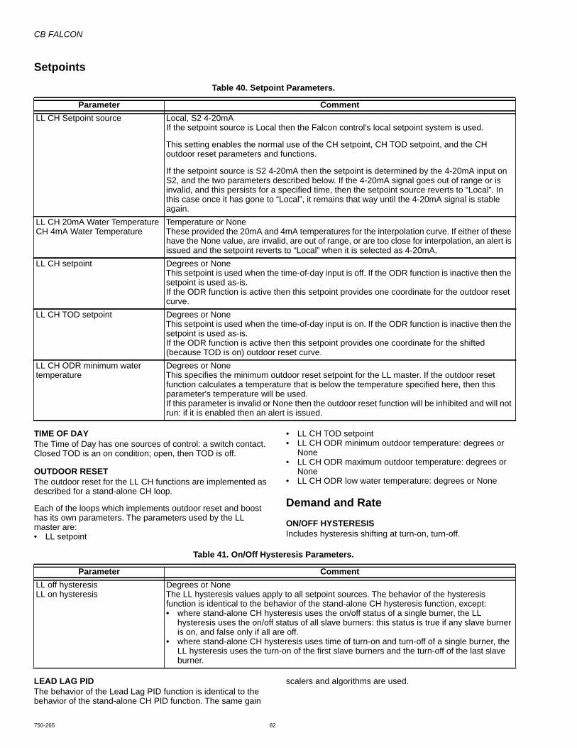
CB FALCON
750-265 82
Setpoints
TIME OF DAYThe Time of Day has one sources of control: a switch contact. Closed TOD is an on condition; open, then TOD is off.
OUTDOOR RESETThe outdoor reset for the LL CH functions are implemented as described for a stand-alone CH loop.
Each of the loops which implements outdoor reset and boost has its own parameters. The parameters used by the LL master are:• LL setpoint
• LL CH TOD setpoint• LL CH ODR minimum outdoor temperature: degrees or
None• LL CH ODR maximum outdoor temperature: degrees or
None• LL CH ODR low water temperature: degrees or None
Demand and Rate
ON/OFF HYSTERESISIncludes hysteresis shifting at turn-on, turn-off.
LEAD LAG PIDThe behavior of the Lead Lag PID function is identical to the behavior of the stand-alone CH PID function. The same gain
scalers and algorithms are used.
Table 40. Setpoint Parameters.
Parameter CommentLL CH Setpoint source Local, S2 4-20mA
If the setpoint source is Local then the Falcon control's local setpoint system is used.
This setting enables the normal use of the CH setpoint, CH TOD setpoint, and the CH outdoor reset parameters and functions.
If the setpoint source is S2 4-20mA then the setpoint is determined by the 4-20mA input on S2, and the two parameters described below. If the 4-20mA signal goes out of range or is invalid, and this persists for a specified time, then the setpoint source reverts to “Local”. In this case once it has gone to “Local”, it remains that way until the 4-20mA signal is stable again.
LL CH 20mA Water TemperatureCH 4mA Water Temperature
Temperature or NoneThese provided the 20mA and 4mA temperatures for the interpolation curve. If either of these have the None value, are invalid, are out of range, or are too close for interpolation, an alert is issued and the setpoint reverts to “Local” when it is selected as 4-20mA.
LL CH setpoint Degrees or NoneThis setpoint is used when the time-of-day input is off. If the ODR function is inactive then the setpoint is used as-is.If the ODR function is active then this setpoint provides one coordinate for the outdoor reset curve.
LL CH TOD setpoint Degrees or NoneThis setpoint is used when the time-of-day input is on. If the ODR function is inactive then the setpoint is used as-is.If the ODR function is active then this setpoint provides one coordinate for the shifted (because TOD is on) outdoor reset curve.
LL CH ODR minimum water temperature
Degrees or NoneThis specifies the minimum outdoor reset setpoint for the LL master. If the outdoor reset function calculates a temperature that is below the temperature specified here, then this parameter's temperature will be used.If this parameter is invalid or None then the outdoor reset function will be inhibited and will not run: if it is enabled then an alert is issued.
Table 41. On/Off Hysteresis Parameters.
Parameter CommentLL off hysteresisLL on hysteresis
Degrees or NoneThe LL hysteresis values apply to all setpoint sources. The behavior of the hysteresis function is identical to the behavior of the stand-alone CH hysteresis function, except:• where stand-alone CH hysteresis uses the on/off status of a single burner, the LL
hysteresis uses the on/off status of all slave burners: this status is true if any slave burner is on, and false only if all are off.
• where stand-alone CH hysteresis uses time of turn-on and turn-off of a single burner, the LL hysteresis uses the turn-on of the first slave burners and the turn-off of the last slave burner.

CB FALCON
83 750-265
RATE ADJUSTMENTWhen the LL - Slave dropout/return compensation parameter specifies a rate adjustment and a rate compensation event occurs (a slave leaves while firing, or a slave returns) then rate adjustment will alter the integrator value so that the commanded rate compensates for the added or lost capacity.
INTEGRATOR COMPENSATIONA stand-alone Falcon includes a feature to smooth the response when a rate override has occurred (such as delta-T rate limit) causing the PID output to be ignored.
Whenever an override has occurred then, at the moment the override ends, the integrator is loaded with a value that causes the PID output to match the current rate, whenever this is possible within the integrator’s limits. The Lead Lag PID will implement similar behavior: The rate allocator will provide a trigger that causes the integrator's value to be recomputed and this trigger will activate whenever a rate allocation limit is released; that is, this event will occur any time the system transitions from the condition in which it is not free to increase the total modulation rate, to the condition where this rate may increase.
Implementation:The examples below are ways in which this may occur, but in implementation what is necessary, first of all, is to use a rate allocator that assigns rate to each slave and can detect when all of the assigned rate is absorbed, or if there is excess requested rate that the firing stages could not absorb.
Then:1. Whenever the system is rate limited, that is, when A) all
firing stages are commanded to their respective maxi-mums and also B) the PID is asking for more heat than that, note that this has occurred by setting a flag and also record total rate that the system absorbed (the total of the commanded maximums, not the PID's requested rate which might include excess).
2. Whenever the rate allocator completes an execution pass and detects that both conditions of step 1 are no longer true (demand has decreased) then it clears the flag.
3. Whenever the rate allocator completes an execution pass and detects both conditions of step 1 are true, and it also detects that the total rate potentially absorbed by the system (the commands have not yet been sent) has increased from the value that was saved when the flag was set, then it re-computes the integrator value based on the old commanded maximum, clears the flag, and actually allocates the old rate that was saved when the flag was set.
Examples include:• The rate allocator has encountered a limit such as base
load (for a “limited” rate allocation scheme) and this limit is released.
• All stages are at their maximum (base load, or max modulation) and one or more stages are rate-limited (such as due to slow-start or stepped modulation limiting due to high stack temperature, etc.) and the rate limited stage recovers, changing from rate-limited to free to modulate. (This is indicated by the Slave Status “slave is modulating” bit: the changing of this bit from false to true is not, itself, a trigger, but while it is true the rate allocator can assign to the slave only the firing rate that it is reporting; thus the release of this might allow more rate to be absorbed by the system. It also might not do this, if for example the slave was in anticondensation and thus the rate limit was maximum modulation rate.)
• All firing stages are at their maximum (base load, or max modulation) and a stage which was OnLeave returns in the firing state and is available for modulation.
• An add-stage is in-progress and all firing burners are at their limits (max modulation rate or base load) and then the new stage becomes available.
This also applies when the system is first starting up, that is, all firing burners are at their limits (zero) because non are firing, and thus when the add-stage is finished the system transitions from no modulation at all, to modulating the first stage.
LEAD LAG BURNER DEMANDLead Lag burner demand will be present when Frost protection burner demand is true, as described the section on Frost protection. For the CH, and DHW demand sources, Lead Lag burner demand will be true when one of these is true and also setpoint demand from the hysteresis block is true.
Rate AllocationThe rate allocator first generates the LL - Slave Command. Except for the Firing state, the value ultimately depends only upon the SlaveState. The values are:• Available• AddStage• SuspendStage depending on whether any other slave stage
is firing, no matter what SlaveState it is in.• Firing• OnLeave - same as SuspendStage This ensures that when
a slave returns and is already firing, it will remain firing until the master decides what to do about that, or if it is not firing it will remain off.
• Disabled - same as Available• Recovering - same as Available
The rate allocator next fills in the modulation rate for all Firing boilers.
The rate allocator also provides functions to return identification of the modulating stage and the last stage, for use by the Add-stage and Drop-stage methods.
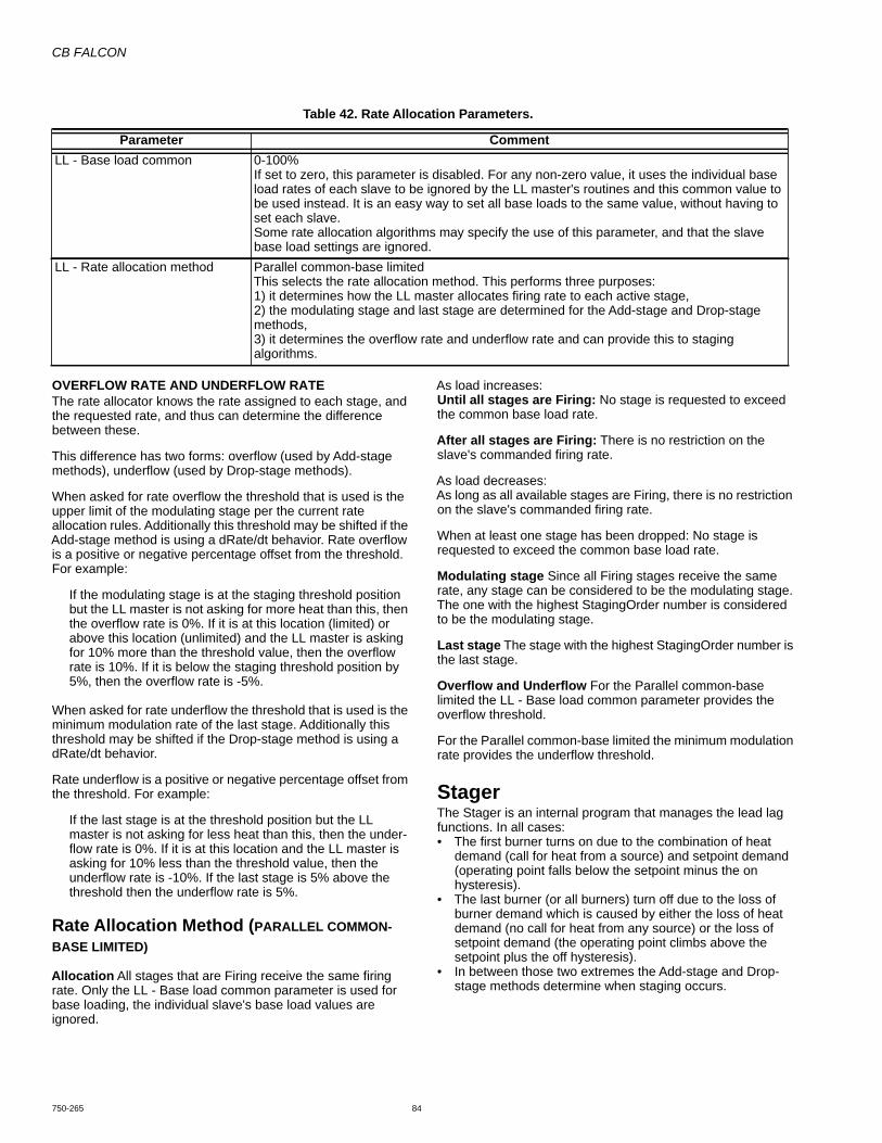
CB FALCON
750-265 84
OVERFLOW RATE AND UNDERFLOW RATEThe rate allocator knows the rate assigned to each stage, and the requested rate, and thus can determine the difference between these.
This difference has two forms: overflow (used by Add-stage methods), underflow (used by Drop-stage methods).
When asked for rate overflow the threshold that is used is the upper limit of the modulating stage per the current rate allocation rules. Additionally this threshold may be shifted if the Add-stage method is using a dRate/dt behavior. Rate overflow is a positive or negative percentage offset from the threshold. For example:
If the modulating stage is at the staging threshold position but the LL master is not asking for more heat than this, then the overflow rate is 0%. If it is at this location (limited) or above this location (unlimited) and the LL master is asking for 10% more than the threshold value, then the overflow rate is 10%. If it is below the staging threshold position by 5%, then the overflow rate is -5%.
When asked for rate underflow the threshold that is used is the minimum modulation rate of the last stage. Additionally this threshold may be shifted if the Drop-stage method is using a dRate/dt behavior.
Rate underflow is a positive or negative percentage offset from the threshold. For example:
If the last stage is at the threshold position but the LL master is not asking for less heat than this, then the under-flow rate is 0%. If it is at this location and the LL master is asking for 10% less than the threshold value, then the underflow rate is -10%. If the last stage is 5% above the threshold then the underflow rate is 5%.
Rate Allocation Method (PARALLEL COMMON-BASE LIMITED)
Allocation All stages that are Firing receive the same firing rate. Only the LL - Base load common parameter is used for base loading, the individual slave's base load values are ignored.
As load increases:Until all stages are Firing: No stage is requested to exceed the common base load rate.
After all stages are Firing: There is no restriction on the slave's commanded firing rate.
As load decreases:As long as all available stages are Firing, there is no restriction on the slave's commanded firing rate.
When at least one stage has been dropped: No stage is requested to exceed the common base load rate.
Modulating stage Since all Firing stages receive the same rate, any stage can be considered to be the modulating stage. The one with the highest StagingOrder number is considered to be the modulating stage.
Last stage The stage with the highest StagingOrder number is the last stage.
Overflow and Underflow For the Parallel common-base limited the LL - Base load common parameter provides the overflow threshold.
For the Parallel common-base limited the minimum modulation rate provides the underflow threshold.
StagerThe Stager is an internal program that manages the lead lag functions. In all cases:• The first burner turns on due to the combination of heat
demand (call for heat from a source) and setpoint demand (operating point falls below the setpoint minus the on hysteresis).
• The last burner (or all burners) turn off due to the loss of burner demand which is caused by either the loss of heat demand (no call for heat from any source) or the loss of setpoint demand (the operating point climbs above the setpoint plus the off hysteresis).
• In between those two extremes the Add-stage and Drop-stage methods determine when staging occurs.
Table 42. Rate Allocation Parameters.
Parameter CommentLL - Base load common 0-100%
If set to zero, this parameter is disabled. For any non-zero value, it uses the individual base load rates of each slave to be ignored by the LL master's routines and this common value to be used instead. It is an easy way to set all base loads to the same value, without having to set each slave.Some rate allocation algorithms may specify the use of this parameter, and that the slave base load settings are ignored.
LL - Rate allocation method Parallel common-base limitedThis selects the rate allocation method. This performs three purposes:1) it determines how the LL master allocates firing rate to each active stage,2) the modulating stage and last stage are determined for the Add-stage and Drop-stage methods,3) it determines the overflow rate and underflow rate and can provide this to staging algorithms.
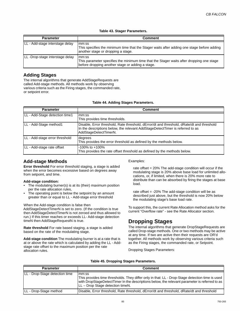
CB FALCON
85 750-265
Adding StagesThe internal algorithms that generate AddStageRequests are called Add-stage methods. All methods work by observing various criteria such as the Firing stages, the commanded rate, or setpoint error.
Add-stage MethodsError threshold For error threshold staging, a stage is added when the error becomes excessive based on degrees away from setpoint, and time.
Add-stage condition:• The modulating burner(s) is at its (their) maximum position
per the rate allocation rules,• The operating point is below the setpoint by an amount
greater than or equal to LL - Add-stage error threshold
When the Add-stage condition is false then AddStageDetectTimerN is set to zero. (If the condition is true then AddStageDetectTimerN is not zeroed and thus allowed to run.) If this timer reaches or exceeds LL- Add-stage detection timeN then AddStageRequestN is true.
Rate threshold For rate based staging, a stage is added based on the rate of the modulating stage.
Add-stage condition The modulating burner is at a rate that is at or above the rate which is calculated by adding the LL - Add-stage rate offset to the maximum position per the rate allocation rules.
Examples:
rate offset = 20% The add-stage condition will occur if the modulating stage is 20% above base load for unlimited allo-cations, or, if limited, when there is 20% more rate to distribute than can be absorbed by firing the stages at base load.
rate offset = -20% The add-stage condition will be as described just above, but the threshold is now 20% below the modulating stage's base load rate.
To support this, the current Rate Allocation method asks for the current “Overflow rate” - see the Rate Allocator section.
Dropping StagesThe internal algorithms that generate DropStageRequests are called Drop-stage methods. One or two methods may be active at any time. If two are active then their requests are OR'd together. All methods work by observing various criteria such as the Firing stages, the commanded rate, or Setpoint.
Dropping Stages Parameters:
Table 43. Stager Parameters.
Parameter CommentLL - Add-stage interstage delay mm:ss
This specifies the minimum time that the Stager waits after adding one stage before adding another stage or dropping a stage.
LL -Drop-stage interstage delay mm:ssThis parameter specifies the minimum time that the Stager waits after dropping one stage before dropping another stage or adding a stage.
Table 44. Adding Stages Parameters.
Parameter CommentLL - Add-Stage detection time1 mm:ss
This provides time thresholds.LL - Add-Stage method1 Disable, Error threshold, Rate threshold, dError/dt and threshold, dRate/dt and threshold
In the descriptions below, the relevant AddStageDetectTimer is referred to as AddStageDetectTimerN.
LL - Add-stage error threshold degreesThis provides the error threshold as defined by the methods below.
LL - Add-stage rate offset -100% to +100%This provides the rate offset threshold as defined by the methods below.
Table 45. Dropping Stages Parameters.
Parameter CommentLL - Drop-Stage detection time mm:ss
This provides time thresholds. They differ only in that: LL - Drop-Stage detection time is used with DropStageDetectTimer In the descriptions below, the relevant parameter is referred to as LL – Drop Stage detection timeN.
LL - Drop-Stage method Disable, Error threshold, Rate threshold, dError/dt and threshold, dRate/dt and threshold

CB FALCON
750-265 86
Drop-stage MethodsError threshold For error threshold staging, a stage is dropped when the error becomes excessive based on degrees away from setpoint and time.
Drop-stage condition:• The modulating burner(s) is at its (their) minimum position
per the rate allocation rules,• The operating point is above the setpoint by an amount
greater than or equal to LL - Drop-stage error thresholdWhen the Drop-stage condition is false then DropStageDetectTimerN is set to zero. (If the condition is true then DropStageDetectTimerN is not zeroed and thus allowed to run.) If this timer reaches or exceeds LL - Drop-stage detection timeN then DropStageRequestN is true.
Rate threshold For rate based staging, a stage is dropped based on the rate of the last stage.
Drop-stage conditionThe modulating burner(s) is at a rate that is at or below the minimum modulation rate plus a rate offset.
Examples:rate offset = 20% The Drop-stage condition will occur when the last stage is less than a threshold that is the minimum modulation rate plus another 20%.
rate offset = 0% The Drop-stage condition will occur when the last stage is at the minimum modulation rate.
rate offset = -20% The Drop-stage condition will occur if the last stage is at minimum modulation and there is 20% less rate to distribute than can be absorbed; that is, the rate allo-cator would like the minimum modulation rate to be lower than it is.
To support this, the current Rate Allocation method asks for the current “Underflow rate” - see “Rate Allocation Methods” on page 84.
SequencerThe sequencer determines which Falcon is next whenever an Add-stage event occurs. It maintains the following variables:
LeadBoilerSeqNum - sequence number of the current lead boiler in the Slave Status table.
Lead BoilerRunTime - the cumulative time that the current lead boiler has been running
In all cases, if a boiler sequence number is needed and LL - Slave sequence order is 0, then the boiler's modbus address is used as its sequence number.
In all cases, if two boilers being compared have the same effective sequence number, then the one that is selected is undefined (either may prevail).
Sequencer Add Boiler SelectionThe sequencer selects the next boiler to be added according to a sorted order. This description assumes this is implemented by assigning an ordering number and that the lowest numbers are the first to be added.• Any Available slaves that have a mode of Use First will have
the lowest ordering numbers. If two or more Use First boilers exist, they are numbered according to their assigned LL - Slave sequence order or Modbus address if this value is zero, as described above.
• Next are slaves that have the mode of Equalize Runtime. When the add boiler routine gets to this group it first invokes the Voluntary Lead Rotation routine (to make sure this is done, but only once) and then selects an Available boiler, if any, ordered according to:
• The first is the lead boiler per the LeadBoilerSeqNum parameter.
• The rest are the other slaves ordered according to the LL –Lag selection method} parameter:
• If this parameter is “Rotate in sequence order”, then they are ordered according to their LL – Slave sequence order or Modbus address if this value is zero, as described above.
LL - Drop-stage error threshold degreesThis provides the error threshold as defined by the methods below.
LL - Drop-stage rate offset -100% to +100%This provides the rate offset threshold as defined by the methods below.
Table 45. Dropping Stages Parameters. (Continued)
Parameter Comment
Table 46. Sequencer Parameters.
Parameter CommentLL - Lead selection method Rotate in sequence order, Measured run time
This determines the selection method for lead selection and sequencing, as described below.LL - Lag selection method Sequence order, Measured run time
This determines the selection method for lag selection and sequencing, as described below.LL - Lead rotation time hh:mm or None
This determines the lead rotation time as defined below.LL - Force lead rotation time hh:mm or None
If this parameter is a non-zero time, then it is used to force the rotation of the lead boiler if it stays on longer than the time specified.

CB FALCON
87 750-265
• If this parameter is “Measured run time” then they are ordered according to their reported run time. If two have the same measured run time, then either may be selected.
• Last are any Available slaves that have a mode of Use Last. These will have the highest numbers. If two or more Use Last boilers exist, they are numbered according to their assigned LL - Slave sequence order or Modbus address if this value is zero, as described above.
Voluntary Lead RotationThe current lead boiler is identified by the LeadBoilerSeqNum value. This value will change when the stager has asked the sequencer for a boiler to add and either:• the boiler identified by LeadBoilerSeqNum is neither
Available nor Firing (i.e. it has a fault or is OnLeave), or• the LeadBoilerRunTime value exceeds LL - Lead rotation
time.
In either of these cases, the algorithm performed is:
If the LL - Lead selection method is “Rotate in sequence order”, then LeadBoilerSeqNum is incremented, and then new lead boiler is the one that is a slave in Equalize Runtime mode that is responding to the LL master (i.e. not OnLeave or Recovering, but it might be Firing), and:
• has a sequence number equal to LeadBoilerSeqNum, or
• If no boiler has this then the closest one with a sequence number greater than this number is used, or
• If no boiler has a greater sequence number, then the one that has the smallest sequence number is used (wrap around).
Otherwise when the LL - Lead selection method is “Measured run time”, then the lead boiler is the one having the lowest Measured run time value. If two have the same measured run time, then either may be selected.
The LeadBoilerRunTime value is then set to zero to give the new lead boiler a fresh allotment.
NOTE: if the old lead boiler is the only one, then this process may end up redesignating this as the “new” lead with a fresh time allotment.
Forced Lead RotationWhen the boiler identified by LeadBoilerSeqNum is firing and also LeadBoilerRunTime reaches the LL - Force lead rotation time parameter time then:
1. The current lead boiler is noted.2. Lead rotation occurs as described above under Volun-
tary Lead Rotation (this changes the designation, but does not change the actual firing status).
SLAVE WRITE: DATAThis allows the slave to accept command messages from a Falcon master.
SLAVE READ: DATA This provides the slave status message to be read by a master. It includes all of the data that is read from a slave.
SLAVE MODE: USE FIRST, EQUALIZE RUNTIME, USE LAST• If set to Use First, then this slave will be used prior to using
other slave slaves with other values. • If this parameter is set to Equalize Runtime, then this slave
will be staged according to a run time equalization. (Any slaves set to Use First will precede any that are set to Equalize Runtime.)
• If this parameter is set to Use Last, then this slave will be used only after all Use First and Equalize Runtime slaves have been brought online.
SLAVE PRIORITY SEQUENCE ORDER: 0-255Slave sequence order is used to determine the order in which the slaves will be used (staged on) for those slaves with the same Slave mode setting. Numbers may be skipped, that is 3 will be first if there is no 1 or 2.
NOTE: For Equalize Runtime purposes, 1 does not mean the slave will be used first every time; that will vary over time based on the master's run time equalization scheme. In this case the sequence number deter-mines the relative order in which slave controls will be used in a round-robin scheme.
If the slave sequence number value is zero, then the slave‘s Modbus address will be used instead.
If two slaves are set to the same mode and both have the same sequence number then an alert will occur and the order in which they are used will be arbitrary and is not guaranteed to be repeatable.
Sequencer Ordering FunctionPart of the sequencer is called by the stager just before the stager runs, to give the sequencer a chance to assign order numbers to stages that very recently turned on, and to maintain these in a sequence. It uses the StagingOrder item in the Slave Status table for this purpose.
The sequencer ordering function examines all slaves and sets to zero the StagingOrder of any stage that is not Firing.
This ensures that any stage that has left the Firing condition recently is no longer in the number sequence.
Next, skipping all of those that have 0 values in StagingOrder it finds the lowest numbered StagingOrder and gives it the value 1, the next receive 2, etc.
Thus if gaps have developed due to a slave dropping out these are filled in.
Finally, the ordering function continues on, giving the next numbers to and Firing stages which have a 0 StagingOrder values (i.e. they recently were added, or they recently returned from OnLeave).
Example:
Before AfterNotfiring 3 0Notfiring 0 0Firing 2 Firing 5 Firing 0 Firing 4

CB FALCON
750-265 88
Sequencer Drop Lag Boiler SelectionWhen the stager asks the sequencer for a lag boiler to drop the sequencer looks at the StagingOrder numbers of all Firing boilers. If only one Firing boiler is found, or none are found, then this selection function returns a value that indicates no boiler may be dropped. Otherwise it returns an identifier for the boiler having the highest StagingOrder number.
Sequencer 1 Minute EventPart of the sequencer is called by the timing service at a 1 minute rate to implement lead rotation.
The 1 minute event checks the boiler identified by LeadBoilerSeqNum. If it is Firing then the LeadBoilerRunTime is incremented.
Alert and Fault message information is shown in APPENDIX C.

CB FALCON
89 750-265
APPENDIX A: PARAMETER GLOSSARTable 47. Parameter Glossary.
Parameter Name Short Description Ref. Page20 mA CH pressure PSI or None
Establishes the pressures for the end points of the 4-20 mA inputs30
4 mA water temperature
DegreesEstablishes temperature for 4 mA input
26
20 mA water temperature
DegreesEstablishes temperature for 20 mA input
26
Absolute max fan speed
The fan will never be commanded to operate above the RPM provided by this parameter, regardless of the rate request.
51
Absolute min fan speed
The fan will never be commanded to operate below the RPM provided by this parameter, regardless of the rate request, except by commanding it to turn off.
51
Alarm silence time Alarms can be silenced for the amount of time given by this parameter. 63Analog output hysteresis
When modulating via 0-10V or 4-20mA, changes in the direction of PID output can be limited by a small amount of hysteresis, to decrease the occurrence of actual control reversals.
52
Annunciation enable This parameter determines whether the Annunciator features of the Falcon are active. When disabled, the Falcon will ignore the Annunciator inputs (because the application does not use this feature).
20
Annunciator 1 location
The location of the contacts monitored by the A1 annunciator input. 61
Annunciator 1 long name
The long name (up to 20 characters) of the A1 annunciator input. 61
Annunciator 2 location
The location of the contacts monitored by the A2 annunciator input. 61
Annunciator 2 long name
The long name (up to 20 characters) of the A2 annunciator input. 61
Annunciator 3 location
The location of the contacts monitored by the A3 annunciator input. 61
Annunciator 3 long name
The long name (up to 20 characters) of the A3 annunciator input. 61
Annunciator 4 location
The location of the contacts monitored by the A4 annunciator input. 61
Annunciator 4 long name
The long name (up to 20 characters) of the A4 annunciator input. 61
Annunciator 5 location
The location of the contacts monitored by the A5 annunciator input. 61
Annunciator 5 long name
The long name (up to 20 characters) of the A5 annunciator input. 61
Annunciator 6 location
The location of the contacts monitored by the A6 annunciator input. 61
Annunciator 6 long name
The long name (up to 20 characters) of the A6 annunciator input. 61
Annunciator 7 location
The location of the contacts monitored by the A7 annunciator input. 61
Annunciator 7 long name
The long name (up to 20 characters) of the A7 annunciator input. 61
Annunciator 8 location
The location of the contacts monitored by the A8 annunciator input. 61
Annunciator 8 long name
The long name (up to 20 characters) of the A8 annunciator input. 61
Annunciator mode The annunciator may be fixed, in which the labels and locations of the inputs is pre-assigned, or programmable in which these things may be altered.
61
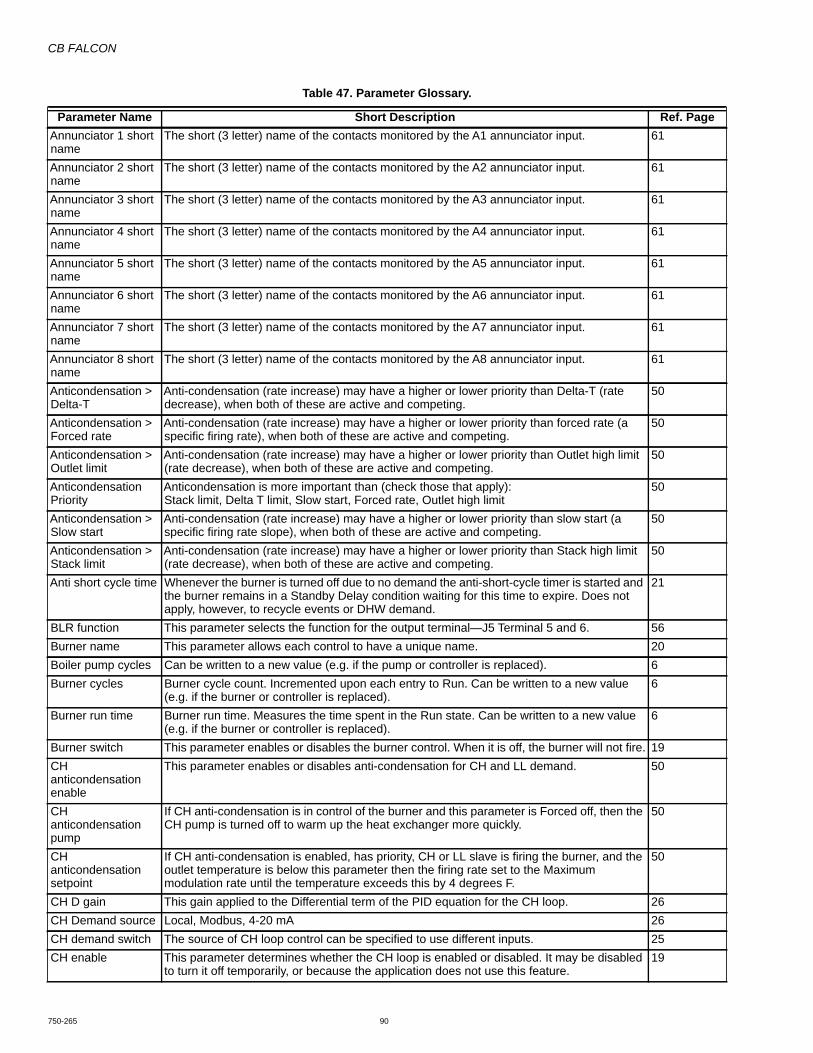
CB FALCON
750-265 90
Annunciator 1 short name
The short (3 letter) name of the contacts monitored by the A1 annunciator input. 61
Annunciator 2 short name
The short (3 letter) name of the contacts monitored by the A2 annunciator input. 61
Annunciator 3 short name
The short (3 letter) name of the contacts monitored by the A3 annunciator input. 61
Annunciator 4 short name
The short (3 letter) name of the contacts monitored by the A4 annunciator input. 61
Annunciator 5 short name
The short (3 letter) name of the contacts monitored by the A5 annunciator input. 61
Annunciator 6 short name
The short (3 letter) name of the contacts monitored by the A6 annunciator input. 61
Annunciator 7 short name
The short (3 letter) name of the contacts monitored by the A7 annunciator input. 61
Annunciator 8 short name
The short (3 letter) name of the contacts monitored by the A8 annunciator input. 61
Anticondensation > Delta-T
Anti-condensation (rate increase) may have a higher or lower priority than Delta-T (rate decrease), when both of these are active and competing.
50
Anticondensation > Forced rate
Anti-condensation (rate increase) may have a higher or lower priority than forced rate (a specific firing rate), when both of these are active and competing.
50
Anticondensation > Outlet limit
Anti-condensation (rate increase) may have a higher or lower priority than Outlet high limit (rate decrease), when both of these are active and competing.
50
Anticondensation Priority
Anticondensation is more important than (check those that apply):Stack limit, Delta T limit, Slow start, Forced rate, Outlet high limit
50
Anticondensation > Slow start
Anti-condensation (rate increase) may have a higher or lower priority than slow start (a specific firing rate slope), when both of these are active and competing.
50
Anticondensation > Stack limit
Anti-condensation (rate increase) may have a higher or lower priority than Stack high limit (rate decrease), when both of these are active and competing.
50
Anti short cycle time Whenever the burner is turned off due to no demand the anti-short-cycle timer is started and the burner remains in a Standby Delay condition waiting for this time to expire. Does not apply, however, to recycle events or DHW demand.
21
BLR function This parameter selects the function for the output terminal—J5 Terminal 5 and 6. 56Burner name This parameter allows each control to have a unique name. 20Boiler pump cycles Can be written to a new value (e.g. if the pump or controller is replaced). 6Burner cycles Burner cycle count. Incremented upon each entry to Run. Can be written to a new value
(e.g. if the burner or controller is replaced).6
Burner run time Burner run time. Measures the time spent in the Run state. Can be written to a new value (e.g. if the burner or controller is replaced).
6
Burner switch This parameter enables or disables the burner control. When it is off, the burner will not fire. 19CH anticondensation enable
This parameter enables or disables anti-condensation for CH and LL demand. 50
CH anticondensation pump
If CH anti-condensation is in control of the burner and this parameter is Forced off, then the CH pump is turned off to warm up the heat exchanger more quickly.
50
CH anticondensation setpoint
If CH anti-condensation is enabled, has priority, CH or LL slave is firing the burner, and the outlet temperature is below this parameter then the firing rate set to the Maximum modulation rate until the temperature exceeds this by 4 degrees F.
50
CH D gain This gain applied to the Differential term of the PID equation for the CH loop. 26CH Demand source Local, Modbus, 4-20 mA 26CH demand switch The source of CH loop control can be specified to use different inputs. 25CH enable This parameter determines whether the CH loop is enabled or disabled. It may be disabled
to turn it off temporarily, or because the application does not use this feature.19
Table 47. Parameter Glossary.
Parameter Name Short Description Ref. Page

CB FALCON
91 750-265
CH forced rate For CH demand, if the CH forced rate time is non-zero, then the firing rate will be held at the rate specified here during that time. This parameter is also needed as the starting point for Slow State, even if the forced rate time is zero.
48
CH forced rate time For CH demand, if this time is non-zero then, upon entry to Run, the firing rate will be held at the CH forced rate.
48
CH frost protection enable
The CH frost protection feature can be enabled to turn the CH pump and possibly fire the burner whenever the CH input sensor is too cold.
41
CH has Priority over Lead Lag
Yes, No, Cancel 19
CH hysteresis step time
The time needed for one step of hysteresis shift, when the off hysteresis threshold or on hysteresis threshold is shifted due to a burner-on or burner-off event, respectively. Zero disables this function.
26
CH I gain This gain applied to the Integral term of the PID equation for the CH loop. 26CH maximum modulation rate
Provides the upper limit of analog output or fan speed during modulation when firing for CH. 51
CH maximum outdoor temperature
This parameter determines the maximum outdoor temperature for the CH outdoor reset graph. At the maximum outdoor temperature the setpoint will be the minimum water temperature.
27
CH minimum outdoor temperature
This parameter determines the X coordinate of one point on the ODR graph. At this outdoor temperature the setpoint will be the CH setpoint (or the CH TOD setpoint, if TOD is on).
27
CH minimum pressure
Provides the minimum Steam Pressure used to calculate the 4-20mA remote controlled setpoint.
30
CH minimum water temperature
This parameter provides the CH setpoint when the outdoor reset temperature is at its defined maximum.
27
CH ODR boost setup
Degrees or None 27
CH ODR boost recovery setup time
mm:ss 27
CH ODR maximum water temperature
This parameter determines one point on the ODR graph. At the maximum outdoor temperature, the setpoint will be the minimum water temperature.
27
CH ODR minimum outdoor temperature
This parameter determines the X coordinate of one point on the ODR graph. At that outdoor temperature, the setpoint will be the CH setpoint (or the CH TOD setpoint, if TOD Is on).
27
CH ODR minimum water temperature
This parameter determines one point on the ODR graph. At the maximum outdoor temperature, the setpoint will be the minimum water temperature.
27
CH off hysteresis The off hysteresis is added to the CH setpoint to determine the temperature at which this demand turns off
26
CH on hysteresis The on hysteresis is subtracted from the Setpoint to determine the temperature at which demand turns on.
26
CH outdoor reset If outdoor reset is enabled then the current outdoor temperature is used to determine the Setpoint by interpolation using CH Setpoint (or CH Time-Of-Day Setpoint if TOD is on), the min water temperature, and the min and max outdoor temperatures.
26
CH P gain This gain applied to the proportional term of the PID equation for the CH loop. 26CH pump cycles Can be written to a new value (e.g. if the pump or controller is replaced). 6CH frost overrun time
This time indicates how long the CH pump should remain on after frost protection demand ends. That is, whenever the pump has been on due to frost protection and then this demand ends, it always continues to run for the time given by this parameter.
41
CH sensor or Inlet The sensor used for modulation and demand may be either the Outlet sensor or a 4-20mA Header sensor input.
25
CH setpoint This Setpoint is used when the time-of-day input is off. If the ODR function is active, this Setpoint provides one coordinate for the outdoor reset curve, as described for the CH Outdoor Reset parameter.
25
CH setpoint source LocalS2 (J8-6) 4-20mA
26
CH slow start enable
This parameter enables or disables the slow start limit function for CH (or LL slave) demand.
49
Table 47. Parameter Glossary.
Parameter Name Short Description Ref. Page
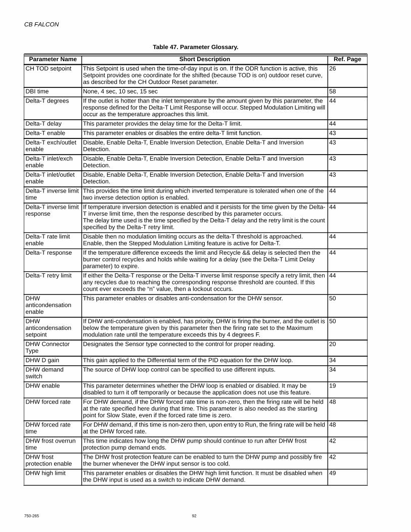
CB FALCON
750-265 92
CH TOD setpoint This Setpoint is used when the time-of-day input is on. If the ODR function is active, this Setpoint provides one coordinate for the shifted (because TOD is on) outdoor reset curve, as described for the CH Outdoor Reset parameter.
26
DBI time None, 4 sec, 10 sec, 15 sec 58Delta-T degrees If the outlet is hotter than the inlet temperature by the amount given by this parameter, the
response defined for the Delta-T Limit Response will occur. Stepped Modulation Limiting will occur as the temperature approaches this limit.
44
Delta-T delay This parameter provides the delay time for the Delta-T limit. 44Delta-T enable This parameter enables or disables the entire delta-T limit function. 43Delta-T exch/outlet enable
Disable, Enable Delta-T, Enable Inversion Detection, Enable Delta-T and Inversion Detection.
43
Delta-T inlet/exch enable
Disable, Enable Delta-T, Enable Inversion Detection, Enable Delta-T and Inversion Detection.
43
Delta-T inlet/outlet enable
Disable, Enable Delta-T, Enable Inversion Detection, Enable Delta-T and Inversion Detection.
43
Delta-T inverse limit time
This provides the time limit during which inverted temperature is tolerated when one of the two inverse detection option is enabled.
44
Delta-T inverse limit response
If temperature inversion detection is enabled and it persists for the time given by the Delta-T inverse limit time, then the response described by this parameter occurs.The delay time used is the time specified by the Delta-T delay and the retry limit is the count specified by the Delta-T retry limit.
44
Delta-T rate limit enable
Disable then no modulation limiting occurs as the delta-T threshold is approached. Enable, then the Stepped Modulation Limiting feature is active for Delta-T.
44
Delta-T response If the temperature difference exceeds the limit and Recycle && delay is selected then the burner control recycles and holds while waiting for a delay (see the Delta-T Limit Delay parameter) to expire.
44
Delta-T retry limit If either the Delta-T response or the Delta-T inverse limit response specify a retry limit, then any recycles due to reaching the corresponding response threshold are counted. If this count ever exceeds the “n” value, then a lockout occurs.
44
DHW anticondensation enable
This parameter enables or disables anti-condensation for the DHW sensor. 50
DHW anticondensation setpoint
If DHW anti-condensation is enabled, has priority, DHW is firing the burner, and the outlet is below the temperature given by this parameter then the firing rate set to the Maximum modulation rate until the temperature exceeds this by 4 degrees F.
50
DHW Connector Type
Designates the Sensor type connected to the control for proper reading. 20
DHW D gain This gain applied to the Differential term of the PID equation for the DHW loop. 34DHW demand switch
The source of DHW loop control can be specified to use different inputs. 34
DHW enable This parameter determines whether the DHW loop is enabled or disabled. It may be disabled to turn it off temporarily or because the application does not use this feature.
19
DHW forced rate For DHW demand, if the DHW forced rate time is non-zero, then the firing rate will be held at the rate specified here during that time. This parameter is also needed as the starting point for Slow State, even if the forced rate time is zero.
48
DHW forced rate time
For DHW demand, if this time is non-zero then, upon entry to Run, the firing rate will be held at the DHW forced rate.
48
DHW frost overrun time
This time indicates how long the DHW pump should continue to run after DHW frost protection pump demand ends.
42
DHW frost protection enable
The DHW frost protection feature can be enabled to turn the DHW pump and possibly fire the burner whenever the DHW input sensor is too cold.
42
DHW high limit This parameter enables or disables the DHW high limit function. It must be disabled when the DHW input is used as a switch to indicate DHW demand.
49
Table 47. Parameter Glossary.
Parameter Name Short Description Ref. Page

CB FALCON
93 750-265
DHW high limit response
If Recycle && hold is selected, the burner control recycles and waits for the DHW temperature to fall. It will remain in this holding condition until the DHW temperature is lower than the DHW high limit temperature minus 5 degrees F.
49
DHW high limit setpoint
If the DHW temperature reaches the value given by this parameter then a response will occur.
49
DHW hysteresis step time
The time needed for one step of hysteresis shift, when the off hysteresis threshold or on hysteresis threshold is shifted due to a burner-on or burner-off event, respectively. Zero disables this function.
34
DHW I gain This gain applied to the Integral term of the PID equation for the DHW loop. 34DHW maximum modulation rate
Provides the upper limit of analog output or fan speed during modulation when firing for DHW.
51
DHW modulation sensor
This parameter selects the source of modulation control for the DHW system. If the selected input is not a temperature (e.g. S1 is steam pressure for a steam control) then an alert occurs and the DHW control subsystem is suspended.
35
DHW off hysteresis The off hysteresis is added to the DHW Setpoint to determine the temperature at which DHW demand turns off
34
DHW on hysteresis The on hysteresis is subtracted from the DHW Setpoint to determine the temperature at which DHW demand turns on.
34
DHW P gain This gain applied to the Proportional term of the PID equation for the DHW loop. 34DHW priority source Disabled, DHW heat demand 19DHW priority method
Boost during priority time, drop after priority time 19
DHW Priority Time ODR Enable
When enabled, the DHW Priority Override Time is derated when the outdoor temperature is below 32°F. When the outdoor temperature is at or above 32°F, the programmed time is used as-is. For temperatures at or below -40°F, the programmed override time is derated to zero (no override).Between 32°F and -40°F, a linear interpolation is used. For example, at -4°F, DWH priority override time is half the value provided by the parameter.
34
DHW priority versus CH
This parameters determines the priority of DHW versus the CH call-for-heat, when both of these are enabled and active. (If DHW has a lower priority, it may be boosted to the highest priority temporarily via the DHW Priority Override Time parameter.)
20
DHW priority versus LL
This parameters determines the priority of DHW versus the LL slave call-for-heat, when more than one source is enabled. (If DHW has a lower priority, it may be boosted to the highest priority temporarily via the DHW Priority Time parameter.)
20
DHW priority override time
If this parameter is non-zero then a DHW demand will take priority over other demand sources for the specified time. If this persists for longer than this time the priority will expire. The timer is reset when demand from the DHW source turns off.
20
DHW pump cycles Can be written to a new value (e.g. if the pump or controller is replaced). 6DHW pump frost protection overrun time
This time indicates how long the DHW pump should remain on after frost protection demand ends. That is, whenever the pump has been on due to frost protection and then this demand ends, it always continues to run for the time given by this parameter.
42
DHW setpoint This Setpoint is used whenever the time-of-day switch is off or not connected (unused). 34DHW slow start enable
This parameter enables or disables the slow start limit function for DHW demand. 49
DHW storage enable
This parameter enables or disables the DHW storage feature. If it is disabled then the other parameters below are ignored.
39
DHW storage off hysteresis
This provides the off hysteresis as an offset that is applied to the DHW storage setpoint, used during DHW storage demand.
39
DHW storage on hysteresis
This provides the on hysteresis as an offset that is applied to the DHW storage setpoint, used during DHW storage demand.
39
DHW storage setpoint
The temperature setpoint that the boiler maintains during the DHW storage time. 39
DHW storage time The time DHW storage temperature is maintained. 39DHW time of day setpoint
This Setpoint is used when the time-of-day switch is on. 34
Table 47. Parameter Glossary.
Parameter Name Short Description Ref. Page

CB FALCON
750-265 94
Exchanger T-Rise enable
This enables/disables temperature rise detection for the heat exchanger sensor S9 (J9 terminal 6).
44
Fan during off cycle rate
If this parameter is non-zero for a control that is enabled as a LL slave, then it provides the modulation rate (e.g. fan speed) that should be used when the LL master indicates this burner should be off but should run its fan at the off cycle rate.
Fan gain down This parameter determines how aggressively the fan controller changes the fan duty cycle when the fan should slow down. It is the gain of a first-order filter (e.g. it is the I gain of a PID control in which the P and D gains are always zero).
52
Fan gain up This parameter determines how aggressively the fan controller changes the fan duty cycle when the fan should speed up. It is the gain of a first-order filter (e.g. it is the I gain of a PID control in which the P and D gains are always zero).
52
Fan min duty cycle Whenever a variable speed fan is on it will never receive a duty cycle less than this parameter's value. It should be set to the duty cycle at which the fan is guaranteed to keep spinning (after it has started) so that it will never stall.
52
Fan speed error response
If fan fails in Run and recycle is selected then the burner control recycles back to the beginning of Prepurge, then continues with the normal burner startup process to attempt to bring the fan up to speed again.
60
Firing rate control If one of the manual modes is chosen then the Manual Rate parameter controls the firing rate during the specified states.
51
Flame sensor type Different kinds of flame detectors may be used. This parameter tells the control what type of sensor is installed.
58
Flame threshold The flame threshold can be adjusted to match various kinds of flame detectors and equipment. It is specified in tenths of volts, where 0.1V = 0.1 microamp for a flame rod.
Forced recycle interval time
After scheduled time of continuous run, system is recycled, specifically if inversion detection is used to provide Safe Start.
58
Frost protection anticondensation enable
When Frost Protection is in control, either the CH or DWH anticondensation function is enabled.
50
Frost protection method
Determines what happens when Frost Protection (from any source) becomes active. 42
Heat exchanger high limit
This enables/disables temperature rise detection for the heat exchanger sensor S9 (J9 terminal 6).
45
Heat exchanger high limit delay
Specifies the delay time that occurs whenever a recycle occurs due to a Heat exchanger high limit event and the specified response includes “Recycle...” The burner will remain in the Standby Hold condition until the delay expires.
45
Heat exchanger high limit response
Specifies response should “Heat exchanger high limit setpoint” threshold is reached. 45
Heat exchanger high limit setpoint
Provides the setpoint at which a response occurs if “Heat exchanger high limit” function is enabled.
45
Heat exchanger retry limit
If the “Heat exchanger high limit response” specifies a retry limit, then any recycles due to reaching the heat exchanger high limit threshold are counted. If this count ever exceeds the “n” value, then a lockout occurs.
45
Heat exchanger T-rise enable
Enabled, Disabled 45
IAS start check enable
This parameter enables a start check for the Interrupted Air Switch input. If enabled, this input must be off before leaving Standby, to prove that it is not shorted.
57
Ignite failure delay When Recycle && hold after retries is selected as the response for an ignition failure, this parameter provides the delay time for the hold.
60
Ignite failure response
If ignition fails then several responses are possible. This parameter selects one of these responses.
60
Ignite failure retries This parameter provides the number of retries for an ignition failure, if the response to failure of ignition includes retries.
60
Igniter on during The igniter may be on throughout the pilot establishing period, or only during the first half of it (early ignition termination). Ignored if DBI is selected.
59
Ignition source Several outputs may be selected as the ignition source. This parameter selects one of these.
60
Table 47. Parameter Glossary.
Parameter Name Short Description Ref. Page

CB FALCON
95 750-265
ILK bounce detection enable
Enable, Disable 57
ILK long name The long name (up to 20 characters) of the ILK annunciator input. 61ILK short name The short (3 letter) name of the contacts monitored by the ILK annunciator input. 61Inlet Connector Type
Designates the sensor type connected to the control for proper reading. 20
Installation data The installer may edit this parameter to provide installation information. 21ILK/IAS open response
During prepurge after a delay to establish airflow and during Ignition, MFEP, and Run, the burner control requires the ILK to remain on. If it opens during these times, this parameter determines the response: either a lockout or a recycle.
57
Interlock (ILK) start check enable
If enabled, the control will check the ILK input as it exits the Standby condition in response to demand. If on, the burner control will hold waiting for it to turn off. If this hold time expires and the ILK is still on, a lockout occurs.
57
Interrupted air switch (IAS) enable
This parameter enables the Interrupted Air Switch input. If enabled it is tested in the same way and during the same states as the ILK input.
57
LCI enable The LCI input may be enabled as a recycle interlock, or this may be disabled. (It is normal to disable the LCI here if it is to be used as a demand input for the CH control loop.)
57
LCI long name The long name (up to 20 characters) of the LCI annunciator input. 61LCI short name The short (3 letter) name of the contacts monitored by the LCI annunciator input. 61Lead Lag frost protection enable
Enabled, Disabled 80
Lead Lag frost protection rate
Set the protection rate as a percentage. 100% represents 100% firing of this boiler, and where 0% or any value less than the boiler's minimum firing rate represents the minimum firing rate.
80
Lead lag time of day setpoint
This Setpoint is used when the time-of-day input is on. If the ODR function is active, this Setpoint provides one coordinate for the shifted (because TOD is on) outdoor reset curve, as described for the LL Outdoor Reset parameter.
Not available at this time.
Lightoff rate This parameter specifies the analog output or fan speed used during Ignition. 51Lightoff rate proving This parameter specifies the input used to confirm the Prepurge rate has been reached. 58LL - Base load rate This specifies the preferred firing rate of a burner, which is used for some types of control. 77LL - Demand-to-firing delay
This delay time is needed by the LL master to determine the length of time to wait between requesting a slave unit to fire and detecting that it has failed to start. It should be set to the total time normally needed for the burner to transition from Standby to Run, including such things as transition to purge rate, prepurge time, transition to lightoff rate, all ignition timings, and include some extra margin.
77
LL - Fan during off-cycle rate
This determines if or where the fan is to be operating during the standby period. 77
LL master enable Disable, Enable 77LL master Modbus port
The LL master may be disabled, enabled. If Disable is selected then all LL master functions are inactive. If Enable is selected then it acts as the active bus master at all times on the Modbus port it is assigned to use by the LL Master Modbus port parameter.
77
LL operation switch This controls the LL master in the same way that the Burner switch controls a stand-alone unit. If “On” then the LL master is enabled to operate. If this parameter is “Off” then the LL master turns off all slaves and enters an idle condition.
77
LL - Slave enable It enables or disables the “LL Slave” Demand and Rate module. 76LL - Slave mode If set to Use First, then this slave will be used prior to using other slave units with other
values. If this parameter is set to Equalize Runtime, then this slave will be staged according to a run time equalization. (Any units set to Use First will precede any that are set to Equalize Runtime.) If this parameter is set to Use Last, then this slave will be used only after all Use First and Equalize Runtime units have been brought online.
76
LL - Slave priority sequence order
Slave sequence order is used to determine the order in which the slave units will be used (staged on) for those units with the same Slave mode setting. Numbers may be skipped, that is 3 will be first if there is no 1 or 2.
77
LL - Slave read This provides the slave status message to be read by a Master. It includes all of the data that is read from a slave.
76
Table 47. Parameter Glossary.
Parameter Name Short Description Ref. Page

CB FALCON
750-265 96
LL - Slave write This allows the slave to accept command messages from a master. 76Manual firing rate This parameter specifies the analog output or fan speed during burner modulation, when
the Firing rate control parameter specifies Manual mode.51
MFEP This parameter provides choices for the duration of the MFEP (main flame establishing period) time. Flame must remain on throughout the MFEP or a response occurs. Not needed and ignored unless the Pilot type is Interrupted.
60
MFEP flame failure response
If flame fails in the Main Flame Establishing Period and recycle is selected then the burner control recycles back to the beginning of Prepurge, then continues with the normal burner startup process to attempt to light the burner again.
60
Minimum modulation rate
Provides the lower limit of analog output or fan speed during modulation (this is for both CH and DHW).
51
Modulation output This parameter selects the modulation output. The Falcon software responds by driving the appropriate circuit to provide modulation of firing rate.
51
Modulation rate source
If the modulation rate source is Local, then the control’s PID algorithm determines the modulation rate.If the modulation rate source is S2 4-20mA, then the modulation rate is determined by the S2 4-20mA modulation routine that exists in prior controls. If this sensor is invalid then the control behaves as if Local were selected.
26
Modulation sensor The selected input provides the temperature clearance for modulation control.As a startup check, if the CH Loop is enabled for a hydronic system, and if the select sensor is not a temperature input, then this causes an alert and forces the CH loop to suspend.
26
NTC sensor type The sensors used may all be the 10K NTC type in which safety sensors are redundant, or all be a 12K NTC type in which no sensors are redundant and external temperature limit devices are required. The latter is for MCBA retrofit compatibility.
57
OEM identification The OEM may provide identification information here. 21Outdoor Connector Type
Designates the Sensor type connected to the control for proper reading. 20
Outdoor frost protection setpoint
This parameter provides the setpoint for frost protection based on outdoor temperature. When the outdoor temperature falls below this threshold then frost protection will be active.
Outlet Connector Type
Designates the Sensor type connected to the control for proper reading. 20
Outlet high limit enable
Used to set the Outlet high limit on or off. 46
Outlet high limit response
If Recycle && hold is selected, the burner control recycles and waits for the outlet temperature to fall. It will remain in this holding condition until the outlet temperature is lower than the outlet high limit temperature minus 5 degrees F.
46
Outlet high limit setpoint
If the outlet temperature reaches the value given by this parameter, a response will occur. 46
Outlet T-Rise enable This enables/disables temperature rise detection for the outlet sensor S3 (J8 terminal 8). 44PFEP This parameter provides choices for the duration of the pilot flame establishing period.
Flame must be on at the end of this period. This parameter is ignored if DBI (Direct Burner Ignition) is selected.
59
PII enable This parameter enables the Pre-Ignition Interlock input. If disabled the PII input is ignored. 57PII long name The long name (up to 20 characters) of the PII annunciator input. 61PII short name The short (3 letter) name of the contacts monitored by the PII annunciator input. 61Pilot test hold If the Pilot type is Interrupted or Intermittent and this parameter is enabled then the burner
control sequence will hold (forever) at 1 second into the Ignition state, while monitoring the flame via a 15 second timer.
57
Pilot type Interrupted pilot turns off after MFEP (main flame establishing period). Intermittent pilot remains on during the Run period (no MFEP). DBI (direct burner ignition) indicates the main flame is lit directly using a 4 second ignition period.
58
Plate preheat delay after tap
Whenever the Preheat block is false, it monitors the Tap demand block's output and operates a timer that ensures preheat will not begin too soon after a tap demand has recently ended.
37
Table 47. Parameter Glossary.
Parameter Name Short Description Ref. Page
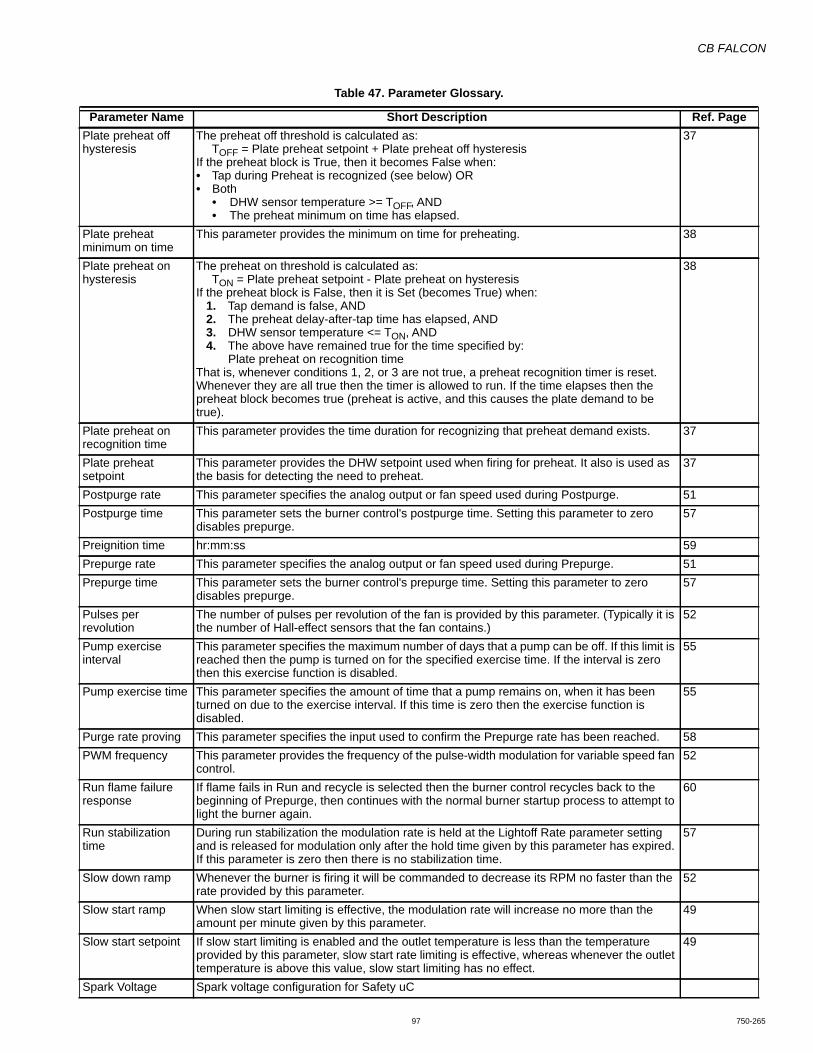
CB FALCON
97 750-265
Plate preheat off hysteresis
The preheat off threshold is calculated as:TOFF = Plate preheat setpoint + Plate preheat off hysteresis
If the preheat block is True, then it becomes False when:• Tap during Preheat is recognized (see below) OR• Both
• DHW sensor temperature >= TOFF, AND• The preheat minimum on time has elapsed.
37
Plate preheat minimum on time
This parameter provides the minimum on time for preheating. 38
Plate preheat on hysteresis
The preheat on threshold is calculated as:TON = Plate preheat setpoint - Plate preheat on hysteresis
If the preheat block is False, then it is Set (becomes True) when:1. Tap demand is false, AND2. The preheat delay-after-tap time has elapsed, AND3. DHW sensor temperature <= TON, AND4. The above have remained true for the time specified by:
Plate preheat on recognition timeThat is, whenever conditions 1, 2, or 3 are not true, a preheat recognition timer is reset. Whenever they are all true then the timer is allowed to run. If the time elapses then the preheat block becomes true (preheat is active, and this causes the plate demand to be true).
38
Plate preheat on recognition time
This parameter provides the time duration for recognizing that preheat demand exists. 37
Plate preheat setpoint
This parameter provides the DHW setpoint used when firing for preheat. It also is used as the basis for detecting the need to preheat.
37
Postpurge rate This parameter specifies the analog output or fan speed used during Postpurge. 51Postpurge time This parameter sets the burner control's postpurge time. Setting this parameter to zero
disables prepurge.57
Preignition time hr:mm:ss 59Prepurge rate This parameter specifies the analog output or fan speed used during Prepurge. 51Prepurge time This parameter sets the burner control's prepurge time. Setting this parameter to zero
disables prepurge.57
Pulses per revolution
The number of pulses per revolution of the fan is provided by this parameter. (Typically it is the number of Hall-effect sensors that the fan contains.)
52
Pump exercise interval
This parameter specifies the maximum number of days that a pump can be off. If this limit is reached then the pump is turned on for the specified exercise time. If the interval is zero then this exercise function is disabled.
55
Pump exercise time This parameter specifies the amount of time that a pump remains on, when it has been turned on due to the exercise interval. If this time is zero then the exercise function is disabled.
55
Purge rate proving This parameter specifies the input used to confirm the Prepurge rate has been reached. 58PWM frequency This parameter provides the frequency of the pulse-width modulation for variable speed fan
control.52
Run flame failure response
If flame fails in Run and recycle is selected then the burner control recycles back to the beginning of Prepurge, then continues with the normal burner startup process to attempt to light the burner again.
60
Run stabilization time
During run stabilization the modulation rate is held at the Lightoff Rate parameter setting and is released for modulation only after the hold time given by this parameter has expired. If this parameter is zero then there is no stabilization time.
57
Slow down ramp Whenever the burner is firing it will be commanded to decrease its RPM no faster than the rate provided by this parameter.
52
Slow start ramp When slow start limiting is effective, the modulation rate will increase no more than the amount per minute given by this parameter.
49
Slow start setpoint If slow start limiting is enabled and the outlet temperature is less than the temperature provided by this parameter, slow start rate limiting is effective, whereas whenever the outlet temperature is above this value, slow start limiting has no effect.
49
Spark Voltage Spark voltage configuration for Safety uC
Table 47. Parameter Glossary.
Parameter Name Short Description Ref. Page
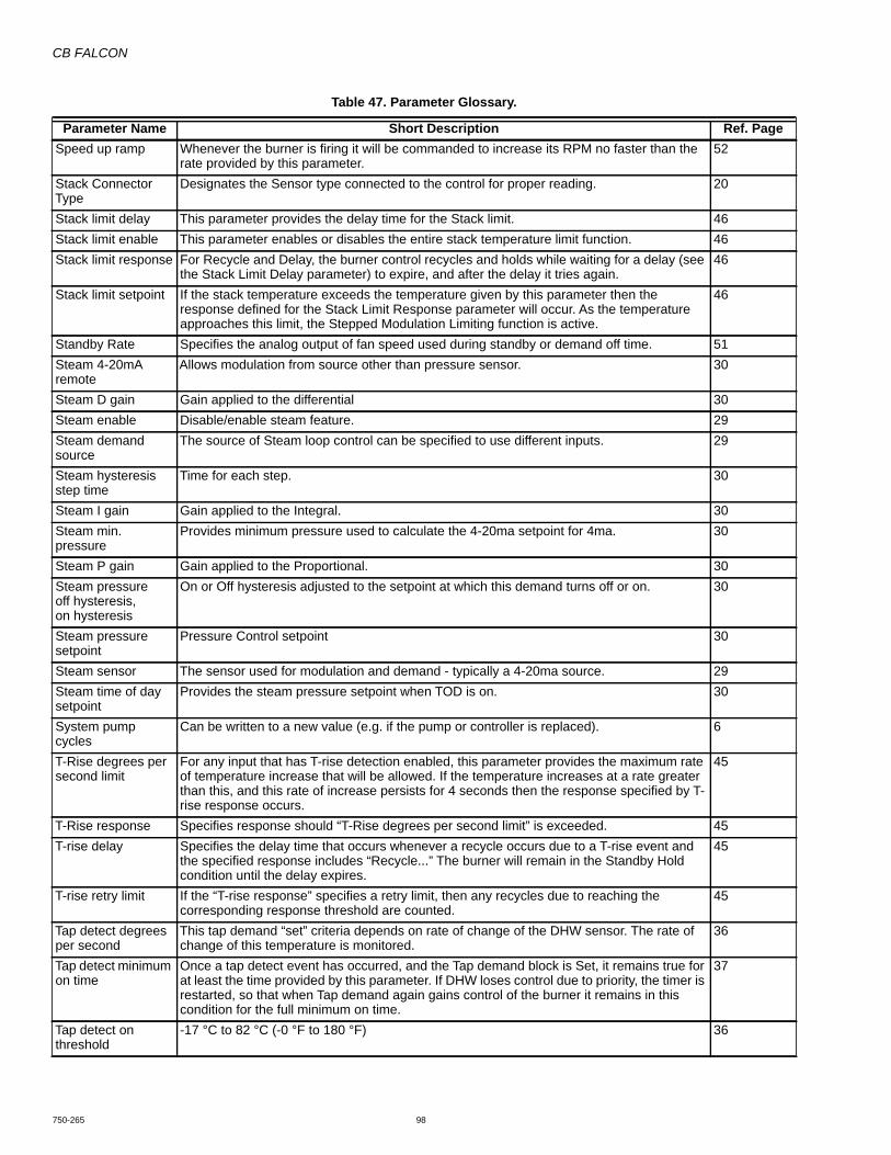
CB FALCON
750-265 98
Speed up ramp Whenever the burner is firing it will be commanded to increase its RPM no faster than the rate provided by this parameter.
52
Stack Connector Type
Designates the Sensor type connected to the control for proper reading. 20
Stack limit delay This parameter provides the delay time for the Stack limit. 46Stack limit enable This parameter enables or disables the entire stack temperature limit function. 46Stack limit response For Recycle and Delay, the burner control recycles and holds while waiting for a delay (see
the Stack Limit Delay parameter) to expire, and after the delay it tries again.46
Stack limit setpoint If the stack temperature exceeds the temperature given by this parameter then the response defined for the Stack Limit Response parameter will occur. As the temperature approaches this limit, the Stepped Modulation Limiting function is active.
46
Standby Rate Specifies the analog output of fan speed used during standby or demand off time. 51Steam 4-20mA remote
Allows modulation from source other than pressure sensor. 30
Steam D gain Gain applied to the differential 30Steam enable Disable/enable steam feature. 29Steam demand source
The source of Steam loop control can be specified to use different inputs. 29
Steam hysteresis step time
Time for each step. 30
Steam I gain Gain applied to the Integral. 30Steam min. pressure
Provides minimum pressure used to calculate the 4-20ma setpoint for 4ma. 30
Steam P gain Gain applied to the Proportional. 30Steam pressureoff hysteresis,on hysteresis
On or Off hysteresis adjusted to the setpoint at which this demand turns off or on. 30
Steam pressure setpoint
Pressure Control setpoint 30
Steam sensor The sensor used for modulation and demand - typically a 4-20ma source. 29Steam time of day setpoint
Provides the steam pressure setpoint when TOD is on. 30
System pump cycles
Can be written to a new value (e.g. if the pump or controller is replaced). 6
T-Rise degrees per second limit
For any input that has T-rise detection enabled, this parameter provides the maximum rate of temperature increase that will be allowed. If the temperature increases at a rate greater than this, and this rate of increase persists for 4 seconds then the response specified by T-rise response occurs.
45
T-Rise response Specifies response should “T-Rise degrees per second limit” is exceeded. 45T-rise delay Specifies the delay time that occurs whenever a recycle occurs due to a T-rise event and
the specified response includes “Recycle...” The burner will remain in the Standby Hold condition until the delay expires.
45
T-rise retry limit If the “T-rise response” specifies a retry limit, then any recycles due to reaching the corresponding response threshold are counted.
45
Tap detect degrees per second
This tap demand “set” criteria depends on rate of change of the DHW sensor. The rate of change of this temperature is monitored.
36
Tap detect minimum on time
Once a tap detect event has occurred, and the Tap demand block is Set, it remains true for at least the time provided by this parameter. If DHW loses control due to priority, the timer is restarted, so that when Tap demand again gains control of the burner it remains in this condition for the full minimum on time.
37
Tap detect on threshold
-17 °C to 82 °C (-0 °F to 180 °F) 36
Table 47. Parameter Glossary.
Parameter Name Short Description Ref. Page
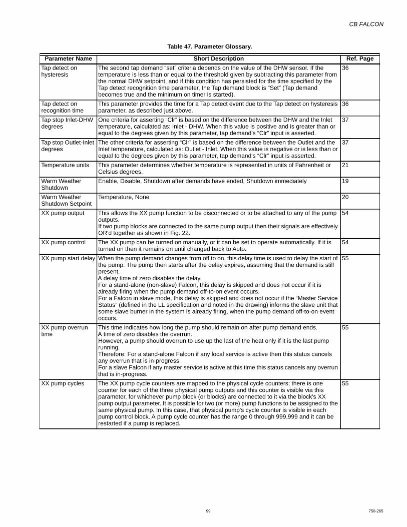
CB FALCON
99 750-265
Tap detect on hysteresis
The second tap demand “set” criteria depends on the value of the DHW sensor. If the temperature is less than or equal to the threshold given by subtracting this parameter from the normal DHW setpoint, and if this condition has persisted for the time specified by the Tap detect recognition time parameter, the Tap demand block is “Set” (Tap demand becomes true and the minimum on timer is started).
36
Tap detect on recognition time
This parameter provides the time for a Tap detect event due to the Tap detect on hysteresis parameter, as described just above.
36
Tap stop Inlet-DHW degrees
One criteria for asserting “Clr” is based on the difference between the DHW and the Inlet temperature, calculated as: Inlet - DHW. When this value is positive and is greater than or equal to the degrees given by this parameter, tap demand’s “Clr” input is asserted.
37
Tap stop Outlet-Inlet degrees
The other criteria for asserting “Clr” is based on the difference between the Outlet and the Inlet temperature, calculated as: Outlet - Inlet. When this value is negative or is less than or equal to the degrees given by this parameter, tap demand’s “Clr” input is asserted.
37
Temperature units This parameter determines whether temperature is represented in units of Fahrenheit or Celsius degrees.
21
Warm Weather Shutdown
Enable, Disable, Shutdown after demands have ended, Shutdown immediately 19
Warm Weather Shutdown Setpoint
Temperature, None 20
XX pump output This allows the XX pump function to be disconnected or to be attached to any of the pump outputs.If two pump blocks are connected to the same pump output then their signals are effectively OR'd together as shown in Fig. 22.
54
XX pump control The XX pump can be turned on manually, or it can be set to operate automatically. If it is turned on then it remains on until changed back to Auto.
54
XX pump start delay When the pump demand changes from off to on, this delay time is used to delay the start of the pump. The pump then starts after the delay expires, assuming that the demand is still present.A delay time of zero disables the delay.For a stand-alone (non-slave) Falcon, this delay is skipped and does not occur if it is already firing when the pump demand off-to-on event occurs.For a Falcon in slave mode, this delay is skipped and does not occur if the “Master Service Status” (defined in the LL specification and noted in the drawing) informs the slave unit that some slave burner in the system is already firing, when the pump demand off-to-on event occurs.
55
XX pump overrun time
This time indicates how long the pump should remain on after pump demand ends.A time of zero disables the overrun.However, a pump should overrun to use up the last of the heat only if it is the last pump running.Therefore: For a stand-alone Falcon if any local service is active then this status cancels any overrun that is in-progress.For a slave Falcon if any master service is active at this time this status cancels any overrun that is in-progress.
55
XX pump cycles The XX pump cycle counters are mapped to the physical cycle counters; there is one counter for each of the three physical pump outputs and this counter is visible via this parameter, for whichever pump block (or blocks) are connected to it via the block's XX pump output parameter. It is possible for two (or more) pump functions to be assigned to the same physical pump. In this case, that physical pump's cycle counter is visible in each pump control block. A pump cycle counter has the range 0 through 999,999 and it can be restarted if a pump is replaced.
55
Table 47. Parameter Glossary.
Parameter Name Short Description Ref. Page
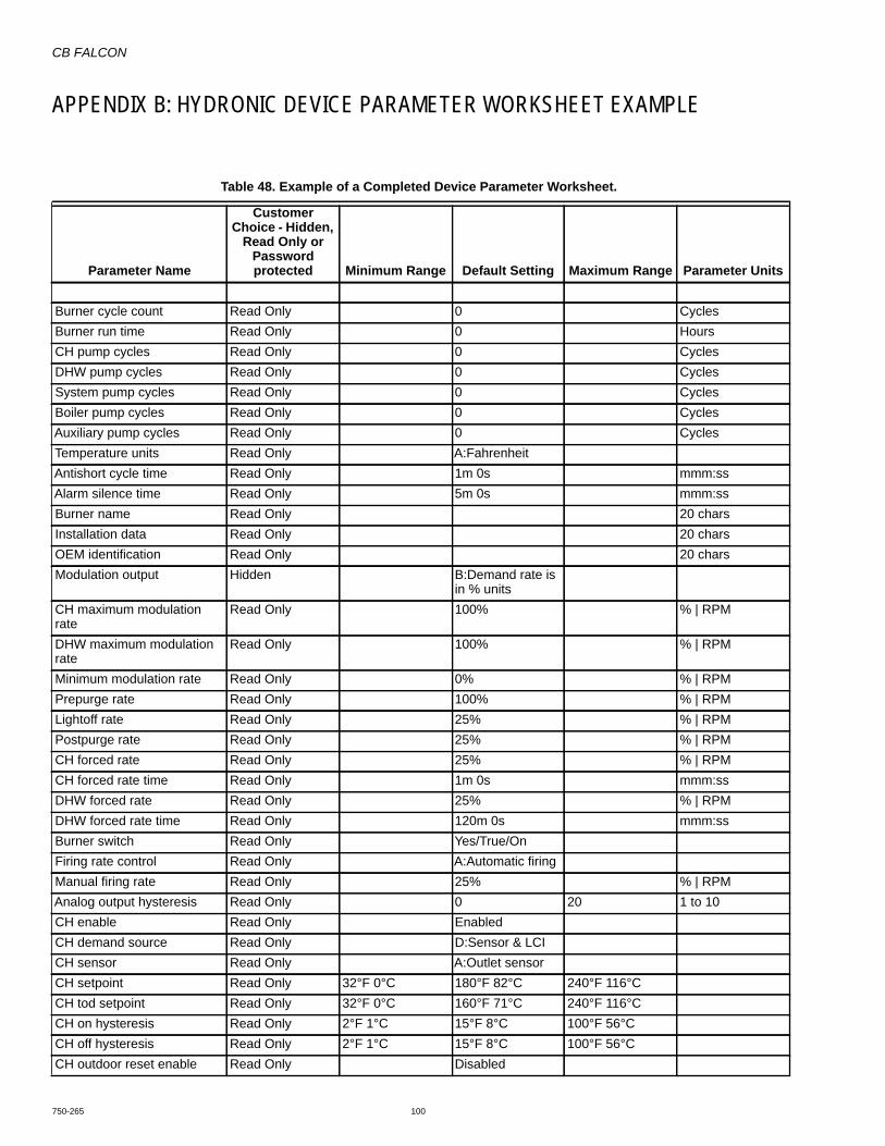
CB FALCON
750-265 100
APPENDIX B: HYDRONIC DEVICE PARAMETER WORKSHEET EXAMPLE
Table 48. Example of a Completed Device Parameter Worksheet.
Parameter Name
Customer Choice - Hidden,
Read Only or Password protected Minimum Range Default Setting Maximum Range Parameter Units
Burner cycle count Read Only 0 CyclesBurner run time Read Only 0 HoursCH pump cycles Read Only 0 CyclesDHW pump cycles Read Only 0 CyclesSystem pump cycles Read Only 0 CyclesBoiler pump cycles Read Only 0 CyclesAuxiliary pump cycles Read Only 0 CyclesTemperature units Read Only A:FahrenheitAntishort cycle time Read Only 1m 0s mmm:ssAlarm silence time Read Only 5m 0s mmm:ssBurner name Read Only 20 charsInstallation data Read Only 20 charsOEM identification Read Only 20 charsModulation output Hidden B:Demand rate is
in % unitsCH maximum modulation rate
Read Only 100% % | RPM
DHW maximum modulation rate
Read Only 100% % | RPM
Minimum modulation rate Read Only 0% % | RPMPrepurge rate Read Only 100% % | RPMLightoff rate Read Only 25% % | RPMPostpurge rate Read Only 25% % | RPMCH forced rate Read Only 25% % | RPMCH forced rate time Read Only 1m 0s mmm:ssDHW forced rate Read Only 25% % | RPMDHW forced rate time Read Only 120m 0s mmm:ssBurner switch Read Only Yes/True/OnFiring rate control Read Only A:Automatic firingManual firing rate Read Only 25% % | RPMAnalog output hysteresis Read Only 0 20 1 to 10CH enable Read Only EnabledCH demand source Read Only D:Sensor & LCICH sensor Read Only A:Outlet sensorCH setpoint Read Only 32°F 0°C 180°F 82°C 240°F 116°CCH tod setpoint Read Only 32°F 0°C 160°F 71°C 240°F 116°CCH on hysteresis Read Only 2°F 1°C 15°F 8°C 100°F 56°CCH off hysteresis Read Only 2°F 1°C 15°F 8°C 100°F 56°CCH outdoor reset enable Read Only Disabled

CB FALCON
101 750-265
CH P gain Read Only 50 400CH I gain Read Only 50 400CH D gain Read Only 0 400CH hysteresis step time Read Only 1m 0s mmm:ssIgnition source Read Only A:Internal ignition
(spark)BLR HSI function Read Only A:Blower motorIgniter on during Read Only A:On throughout
PFEPPilot type Read Only A:Interrupted (off
during Run)Flame sensor type Read Only A:No flame sensorPurge rate proving Read Only B:Prove via HFS
terminalLightoff rate proving Read Only B:Prove via LFS
terminalPrepurge time Read Only 0m 30s mmm:ssPreignition time Read Only 0m 0s mmm:ssPFEP Read Only C:10 secondsMFEP Read Only C:10 secondsRun stabilization time Read Only 0m 10s mmm:ssPostpurge time Read Only 0m 15s mmm:ssInterlock start check enable Read Only DisabledInterlock open response Read Only A:LockoutIgnite failure response Read Only A:LockoutIgnite failure retries Read Only A:Number of
retries not setIgnite failure delay Read Only 5m 0s mmm:ssMFEP flame failure response Read Only A:LockoutRun flame failure response Read Only A:LockoutPilot test hold Hidden DisabledNTC sensor type Read Only A:10K dual safetyInterrupted air switch enable Read Only A:no IASIAS start check enable Hidden EnabledLCI enable Read Only EnabledPII enable Read Only EnabledFlame threshold Read Only 2 8 140 .1 Volts/uAAbsolute max fan speed Read Only 500 5000 7000 RPMAbsolute min fan speed Read Only 500 800 5000 RPMPWM frequency Read Only D:3000 HzPulses per revolution Read Only 1 3 10Fan speed up ramp Read Only 0 RPM/secFan slow down ramp Read Only 0 RPM/secFan gain up Read Only 50 100Fan gain down Read Only 50 100
Table 48. Example of a Completed Device Parameter Worksheet. (Continued)
Parameter Name
Customer Choice - Hidden,
Read Only or Password protected Minimum Range Default Setting Maximum Range Parameter Units

CB FALCON
750-265 102
Fan min duty cycle Read Only 10 100 0-100%CH pump output Read Only A:No pump
assignmentCH pump control Read Only A:Automatic pump
controlCH pump overrun time Read Only 1m 0s mmm:ssCH pump frost protection overrun time
Read Only 1m 0s mmm:ss
DHW pump output Read Only A:No pump assignment
DHW pump control Read Only A:Automatic pump control
DHW pump overrun time Read Only 1m 0s mmm:ssDHW pump frost protection overrun time
Read Only 1m 0s mmm:ss
DHW pump start delay Read Only 0m 0s mmm:ssBoiler pump output Read Only A:No pump
assignmentBoiler pump control Read Only A:Automatic pump
controlBoiler pump overrun time Read Only 1m 0s mmm:ssAuxiliary pump output Read Only A:No pump
assignmentAuxiliary pump control Read Only A:Automatic pump
controlAuxiliary pump on when Read Only A:Auxiliary ON
when CH pump is ON
System pump output Read Only A:No pump assignment
System pump control Read Only A:Automatic pump control
System pump overrun time Read Only 1m 0s mmm:ssPump exercise interval Read Only 0 DaysPump exercise time Read Only 0m 0s mmm:ssAnnunciation enable Read Only EnabledAnnunciator 1 location Read Only E:No annunciation
for this terminalAnnunciator1 short name Read Only A1 3 charsAnnunciator 1 long name Read Only Annunciator 1 20 charsAnnunciator 2 location Read Only E:No annunciation
for this terminalAnnunciator2 short name Read Only A2 3 charsAnnunciator 2 long name Read Only Annunciator2 20 charsAnnunciator 3 location Read Only E:No annunciation
for this terminalAnnunciator3 short name Read Only A3 3 charsAnnunciator 3 long name Read Only Annunciator3 20 chars
Table 48. Example of a Completed Device Parameter Worksheet. (Continued)
Parameter Name
Customer Choice - Hidden,
Read Only or Password protected Minimum Range Default Setting Maximum Range Parameter Units

CB FALCON
103 750-265
Annunciator 4 location Read Only A:No annunciation for this terminal
Annunciator4 short name Read Only A4 3 charsAnnunciator 4 long name Read Only Annunciator4 20 charsAnnunciator 5 location Read Only E:No annunciation
for this terminalAnnunciator5 short name Read Only A5 3 charsAnnunciator 5 long name Read Only Annunciator5 20 charsAnnunciator 6 location Read Only E:No annunciation
for this terminalAnnunciator6 short name Read Only A6 3 charsAnnunciator 6 long name Read Only Annunciator6 20 charsAnnunciator 7 location Read Only E:No annunciation
for this terminalAnnunciator7 short name Read Only A7 3 charsAnnunciator 7 long name Read Only Annunciator7 20 charsAnnunciator 8 location Read Only E:No annunciation
for this terminalAnnunciator8 short name Read Only A8 3 charsAnnunciator 8 long name Read Only Annunciator8 20 charsPII short name Read Only PII 3 charsPII long name Read Only Pre-Ignition ILK 20 charsLCI short name Read Only LCI 3 charsLCI long name Read Only Load Control Input 20 charsILK short name Read Only ILK 3 charsILK long name Read Only Interlock 20 charsDHW enable Read Only DisabledDHW demand source Read Only A:DHW sensor
onlyDHW has priority over CH Read Only No/False/OffDHW has priority over LL Read Only No/False/OffDHW priority time Read Only 30m 0s mmm:ssDHW setpoint Read Only 32°F 0°C 140°F 60°C 240°F 116°CDHW tod setpoint Read Only 32°F 0°C 120°F 49°C 240°F 116°CDHW on hysteresis Read Only 2°F 1°C 5°F 3°C 100°F 56°CDHW off hysteresis Read Only 2°F 1°C 5°F 3°C 100°F 56°CDHW P gain Read Only 0 50 400DHW I gain Read Only 0 50 400DHW D gain Read Only 0 50 400DHW hysteresis step time Read Only 0m 0s mmm:ssOutlet high limit setpoint Read Only 32°F 0°C 220°F 104°C 240°F 116°COutlet high limit response Read Only [ A B #c #d ] A:LockoutStack limit enable Read Only DisabledStack limit setpoint Read Only 32°F 0°C 200°F 93°C 500°F 260°CStack limit response Read Only [ A #b C #d ] A:Lockout
Table 48. Example of a Completed Device Parameter Worksheet. (Continued)
Parameter Name
Customer Choice - Hidden,
Read Only or Password protected Minimum Range Default Setting Maximum Range Parameter Units
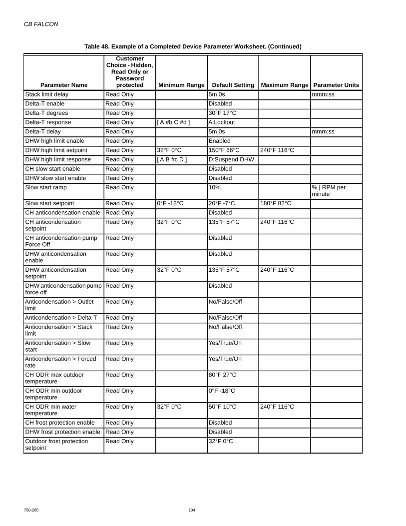
CB FALCON
750-265 104
Stack limit delay Read Only 5m 0s mmm:ssDelta-T enable Read Only DisabledDelta-T degrees Read Only 30°F 17°CDelta-T response Read Only [ A #b C #d ] A:LockoutDelta-T delay Read Only 5m 0s mmm:ssDHW high limit enable Read Only EnabledDHW high limit setpoint Read Only 32°F 0°C 150°F 66°C 240°F 116°CDHW high limit response Read Only [ A B #c D ] D:Suspend DHWCH slow start enable Read Only DisabledDHW slow start enable Read Only DisabledSlow start ramp Read Only 10% % | RPM per
minuteSlow start setpoint Read Only 0°F -18°C 20°F -7°C 180°F 82°CCH anticondensation enable Read Only DisabledCH anticondensation setpoint
Read Only 32°F 0°C 135°F 57°C 240°F 116°C
CH anticondensation pump Force Off
Read Only Disabled
DHW anticondensation enable
Read Only Disabled
DHW anticondensation setpoint
Read Only 32°F 0°C 135°F 57°C 240°F 116°C
DHW anticondensation pump force off
Read Only Disabled
Anticondensation > Outlet limit
Read Only No/False/Off
Anticondensation > Delta-T Read Only No/False/OffAnticondensation > Stack limit
Read Only No/False/Off
Anticondensation > Slow start
Read Only Yes/True/On
Anticondensation > Forced rate
Read Only Yes/True/On
CH ODR max outdoor temperature
Read Only 80°F 27°C
CH ODR min outdoor temperature
Read Only 0°F -18°C
CH ODR min water temperature
Read Only 32°F 0°C 50°F 10°C 240°F 116°C
CH frost protection enable Read Only DisabledDHW frost protection enable Read Only DisabledOutdoor frost protection setpoint
Read Only 32°F 0°C
Table 48. Example of a Completed Device Parameter Worksheet. (Continued)
Parameter Name
Customer Choice - Hidden,
Read Only or Password protected Minimum Range Default Setting Maximum Range Parameter Units
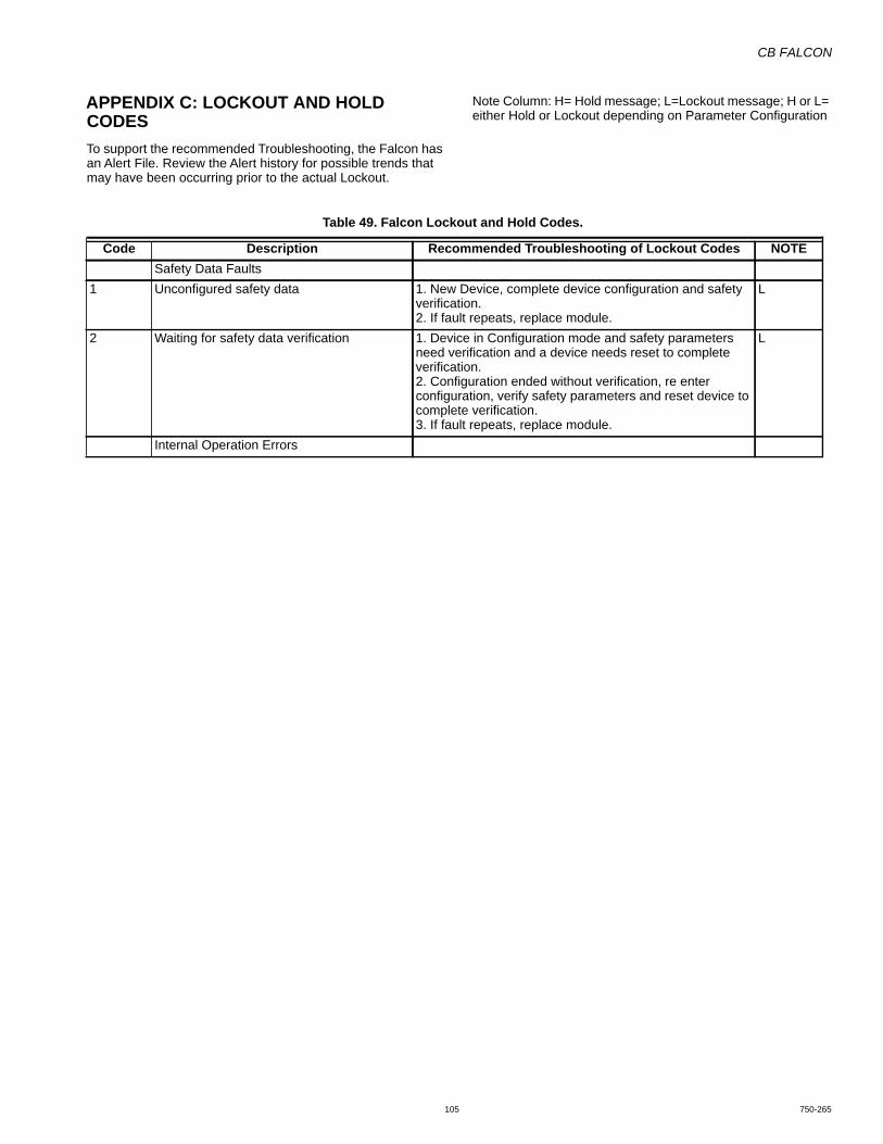
CB FALCON
105 750-265
APPENDIX C: LOCKOUT AND HOLD CODESTo support the recommended Troubleshooting, the Falcon has an Alert File. Review the Alert history for possible trends that may have been occurring prior to the actual Lockout.
Note Column: H= Hold message; L=Lockout message; H or L= either Hold or Lockout depending on Parameter Configuration
Table 49. Falcon Lockout and Hold Codes.
Code Description Recommended Troubleshooting of Lockout Codes NOTESafety Data Faults
1 Unconfigured safety data 1. New Device, complete device configuration and safety verification.2. If fault repeats, replace module.
L
2 Waiting for safety data verification 1. Device in Configuration mode and safety parameters need verification and a device needs reset to complete verification.2. Configuration ended without verification, re enter configuration, verify safety parameters and reset device to complete verification.3. If fault repeats, replace module.
L
Internal Operation Errors

CB FALCON
750-265 106
3 Internal fault: Hardware fault Internal Fault.1. Reset Module. 2. If fault repeats, replace module.
H4 Internal fault: Safety Relay key feedback
errorH
5 Internal fault: Unstable power (DCDC) output
H
6 Internal fault: Invalid processor clock H7 Internal fault: Safety relay drive error H8 Internal fault: Zero crossing not detected H9 Internal fault: Flame bias out of range H10 Internal fault: Invalid Burner control state L11 Internal fault: Invalid Burner control state flag L12 Internal fault: Safety relay drive cap short H13 Internal fault: PII shorted to ILK H or L14 Internal fault: HFS shorted to LCI H or L15 Internal fault: Safety relay test failed due to
feedback ONL
16 Internal fault: Safety relay test failed due to safety relay OFF
L
17 Internal fault: Safety relay test failed due to safety relay not OFF
L
18 Internal fault: Safety relay test failed due to feedback not ON
L
19 Internal fault: Safety RAM write L20 Internal fault: Flame ripple and overflow H21 Internal fault: Flame number of sample
mismatchH
22 Internal fault: Flame bias out of range H23 Internal fault: Bias changed since heating
cycle startsH
24 Internal fault: Spark voltage stuck low or high H25 Internal fault: Spark voltage changed too
much during flame sensing timeH
26 Internal fault: Static flame ripple H27 Internal fault: Flame rod shorted to ground
detectedH
28 Internal fault: A/D linearity test fails H29 Internal fault: Flame bias cannot be set in
rangeH
30 Internal fault: Flame bias shorted to adjacent pin
H
31 Internal fault: SLO electronics unknown error H32-46 Internal fault: Safety Key 0 through 14 L
System Errors47 Flame Rod to ground leakage H48 Static flame (not flickering) H49 24VAC voltage low/high 1. Check the Module and display connections.
2. Check the Module power supply and make sure that both frequency, voltage and VA meet the specifications.
H
Table 49. Falcon Lockout and Hold Codes. (Continued)
Code Description Recommended Troubleshooting of Lockout Codes NOTE

CB FALCON
107 750-265
50 Modulation fault Internal sub-system fault. 1. Review alert messages for possible trends.2. Correct possible problems.3. If fault persists, replace module.
H51 Pump fault H52 Motor tachometer fault H
53 AC inputs phase reversed 1. Check the Module and display connections. 2. Check the Module power supply and make sure that both frequency and voltage meet the specifications. 3. On 24Vac applications, assure that J4-10 and J8-2 are connected together.
L
54 Safety GVT model ID doesn't match application's model ID
L
55 Application configuration data block CRC errors
L
56-57 RESERVED58 Internal fault: HFS shorted to IAS Internal Fault.
1. Reset Module. 2. If fault repeats, replace module.
L59 Internal Fault: Mux pin shorted L
Normal Event Status60 Internal Fault: HFS shorted to LFS L61 Anti short cycle Will not be a lockout fault. Hold Only. H62 Fan speed not proved H63 LCI OFF 1. Check wiring and correct any faults.
2. Check Interlocks connected to the LCI to assure proper function. 3. Reset and sequence the module; monitor the LCI status. 4. If code persists, replace the module.
H
64 PII OFF 1. Check wiring and correct any faults. 2. Check Preignition Interlock switches to assure proper functioning. 3. Check the valve operation. 4. Reset and sequence the module; monitor the PII status.5. If code persists, replace the module.
H or L
65 Interrupted Airflow Switch OFF 1. Check wiring and correct any possible shorts. 2. Check airflow switches to assure proper functioning. 3. Check the fan/blower operation. 4. Reset and sequence the module; monitor the airflow status. 5. If code persists, replace the module.
H or L66 Interrupted Airflow Switch ON H or L
67 ILK OFF 1. Check wiring and correct any possible shorts. 2. Check Interlock (ILK) switches to assure proper function. 3. Verify voltage through the interlock string to the interlock input with a voltmeter. 4. If steps 1-3 are correct and the fault persists, replace the
H or L68 ILK ON H or L
69 Pilot test hold 1. Verify Run/Test is changed to Run. 2. Reset Module. 3. If fault repeats, replace module.
H
70 Wait for leakage test completion 1. Internal Fault. Reset Module. 2. If fault repeats, replace module.
H
71-77 RESERVED78 Demand Lost in Run 1. Check wiring and correct any possible errors.
2. If previous steps are correct and fault persists, replace the module.
H
79 Outlet high limit 1. Check wiring and correct any possible errors. 2. Replace the Outlet high limit. 3. If previous steps are correct and fault persists, replace the module.
H or L
Table 49. Falcon Lockout and Hold Codes. (Continued)
Code Description Recommended Troubleshooting of Lockout Codes NOTE
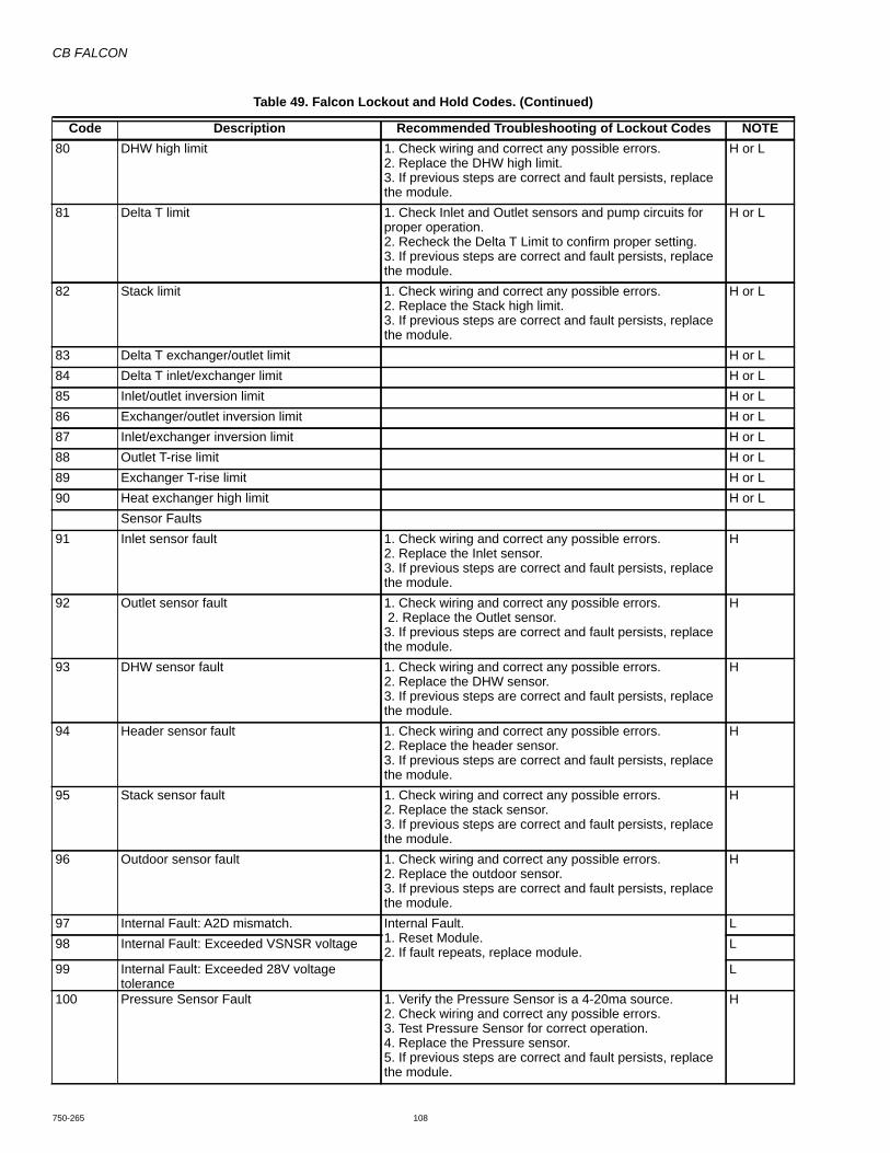
CB FALCON
750-265 108
80 DHW high limit 1. Check wiring and correct any possible errors. 2. Replace the DHW high limit. 3. If previous steps are correct and fault persists, replace the module.
H or L
81 Delta T limit 1. Check Inlet and Outlet sensors and pump circuits for proper operation. 2. Recheck the Delta T Limit to confirm proper setting. 3. If previous steps are correct and fault persists, replace the module.
H or L
82 Stack limit 1. Check wiring and correct any possible errors. 2. Replace the Stack high limit. 3. If previous steps are correct and fault persists, replace the module.
H or L
83 Delta T exchanger/outlet limit H or L84 Delta T inlet/exchanger limit H or L85 Inlet/outlet inversion limit H or L86 Exchanger/outlet inversion limit H or L87 Inlet/exchanger inversion limit H or L88 Outlet T-rise limit H or L89 Exchanger T-rise limit H or L90 Heat exchanger high limit H or L
Sensor Faults91 Inlet sensor fault 1. Check wiring and correct any possible errors.
2. Replace the Inlet sensor. 3. If previous steps are correct and fault persists, replace the module.
H
92 Outlet sensor fault 1. Check wiring and correct any possible errors. 2. Replace the Outlet sensor. 3. If previous steps are correct and fault persists, replace the module.
H
93 DHW sensor fault 1. Check wiring and correct any possible errors. 2. Replace the DHW sensor. 3. If previous steps are correct and fault persists, replace the module.
H
94 Header sensor fault 1. Check wiring and correct any possible errors. 2. Replace the header sensor. 3. If previous steps are correct and fault persists, replace the module.
H
95 Stack sensor fault 1. Check wiring and correct any possible errors. 2. Replace the stack sensor. 3. If previous steps are correct and fault persists, replace the module.
H
96 Outdoor sensor fault 1. Check wiring and correct any possible errors. 2. Replace the outdoor sensor. 3. If previous steps are correct and fault persists, replace the module.
H
97 Internal Fault: A2D mismatch. Internal Fault.1. Reset Module. 2. If fault repeats, replace module.
L98 Internal Fault: Exceeded VSNSR voltage L
99 Internal Fault: Exceeded 28V voltage tolerance
L
100 Pressure Sensor Fault 1. Verify the Pressure Sensor is a 4-20ma source.2. Check wiring and correct any possible errors. 3. Test Pressure Sensor for correct operation.4. Replace the Pressure sensor. 5. If previous steps are correct and fault persists, replace the module.
H
Table 49. Falcon Lockout and Hold Codes. (Continued)
Code Description Recommended Troubleshooting of Lockout Codes NOTE
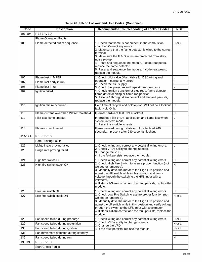
CB FALCON
109 750-265
101-104 RESERVEDFlame Operation Faults
105 Flame detected out of sequence 1. Check that flame is not present in the combustion chamber. Correct any errors. 2. Make sure that the flame detector is wired to the correct terminal. 3. Make sure the F & G wires are protected from stray noise pickup. 4. Reset and sequence the module, if code reappears, replace the flame detector. 5. Reset and sequence the module, if code reappears, replace the module.
H or L
106 Flame lost in MFEP 1. Check pilot valve (Main Valve for DSI) wiring and operation - correct any errors.2. Check the fuel supply.3. Check fuel pressure and repeat turndown tests.4. Check ignition transformer electrode, flame detector, flame detector siting or flame rod position.5. If steps 1 through 4 are correct and the fault persists, replace the module.
L107 Flame lost early in run L108 Flame lost in run L109 Ignition failed L
110 Ignition failure occurred Hold time of recycle and hold option. Will not be a lockout fault. Hold Only.
H
111 Flame current lower than WEAK threshold Internal hardware test. Not a lockout, H112 Pilot test flame timeout Interrupted Pilot or DSI application and flame lost when
system in “test” mode. 1. Reset the module to restart.
L
113 Flame circuit timeout Flame sensed during Initiate or off cycle, hold 240 seconds, if present after 240 seconds, lockout.
L
114-121 RESERVEDRate Proving Faults
122 Lightoff rate proving failed 1. Check wiring and correct any potential wiring errors. 2. Check VFDs ability to change speeds. 3. Change the VFD 4. If the fault persists, replace the module.
L123 Purge rate proving failed L
124 High fire switch OFF 1. Check wiring and correct any potential wiring errors. 2. Check High Fire Switch to assure proper function (not welded or jumpered). 3. Manually drive the motor to the High Fire position and adjust the HF switch while in this position and verify voltage through the switch to the HFS input with a voltmeter. 4. If steps 1-3 are correct and the fault persists, replace the module.
H125 High fire switch stuck ON H
126 Low fire switch OFF 1. Check wiring and correct any potential wiring errors. 2. Check Low Fire Switch to assure proper function (not welded or jumpered). 3. Manually drive the motor to the High Fire position and adjust the LF switch while in this position and verify voltage through the switch to the LFS input with a voltmeter. 4. If steps 1-3 are correct and the fault persists, replace the module.
H127 Low fire switch stuck ON H or L
128 Fan speed failed during prepurge 1. Check wiring and correct any potential wiring errors. 2. Check VFDs ability to change speeds. 3. Change the VFD 4. If the fault persists, replace the module.
H or L129 Fan speed failed during preignition H or L130 Fan speed failed during ignition H or L131 Fan movement detected during standby H132 Fan speed failed during run H133-135 RESERVED
Start Check Faults
Table 49. Falcon Lockout and Hold Codes. (Continued)
Code Description Recommended Troubleshooting of Lockout Codes NOTE
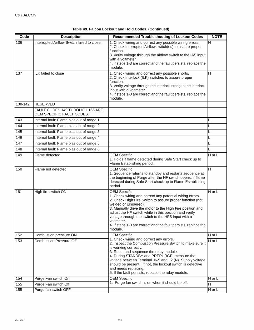
CB FALCON
750-265 110
136 Interrupted Airflow Switch failed to close 1. Check wiring and correct any possible wiring errors. 2. Check Interrupted Airflow switch(es) to assure proper function. 3. Verify voltage through the airflow switch to the IAS input with a voltmeter. 4. If steps 1-3 are correct and the fault persists, replace the module.
H
137 ILK failed to close 1. Check wiring and correct any possible shorts. 2. Check Interlock (ILK) switches to assure proper function. 3. Verify voltage through the interlock string to the interlock input with a voltmeter. 4. If steps 1-3 are correct and the fault persists, replace the module.
H
138-142 RESERVEDFAULT CODES 149 THROUGH 165 ARE OEM SPECIFIC FAULT CODES.
143 Internal fault: Flame bias out of range 1 L144 Internal fault: Flame bias out of range 2 L145 Internal fault: Flame bias out of range 3 L146 Internal fault: Flame bias out of range 4 L147 Internal fault: Flame bias out of range 5 L148 Internal fault: Flame bias out of range 6 L149 Flame detected OEM Specific
1. Holds if flame detected during Safe Start check up to Flame Establishing period.
H or L
150 Flame not detected OEM Specific1. Sequence returns to standby and restarts sequence at the beginning of Purge after the HF switch opens. if flame detected during Safe Start check up to Flame Establishing period.
H
151 High fire switch ON OEM Specific1. Check wiring and correct any potential wiring errors.2. Check High Fire Switch to assure proper function (not welded or jumpered). 3. Manually drive the motor to the High Fire position and adjust the HF switch while in this position and verify voltage through the switch to the HFS input with a voltmeter. 4. If steps 1-3 are correct and the fault persists, replace the module.
H or L
152 Combustion pressure ON OEM Specific1. Check wiring and correct any errors.2. Inspect the Combustion Pressure Switch to make sure it is working correctly.3. Reset and sequence the relay module.4. During STANDBY and PREPURGE, measure the voltage between Terminal J6-5 and L2 (N). Supply voltage should be present. If not, the lockout switch is defective and needs replacing.5. If the fault persists, replace the relay module.
H or L153 Combustion Pressure Off H or L
154 Purge Fan switch On OEM Specific1. Purge fan switch is on when it should be off.
H or L155 Purge Fan switch Off H155 Purge fan switch OFF H or L
Table 49. Falcon Lockout and Hold Codes. (Continued)
Code Description Recommended Troubleshooting of Lockout Codes NOTE
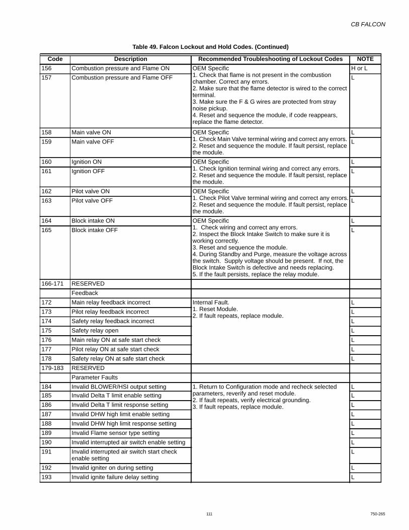
CB FALCON
111 750-265
156 Combustion pressure and Flame ON OEM Specific1. Check that flame is not present in the combustion chamber. Correct any errors. 2. Make sure that the flame detector is wired to the correct terminal. 3. Make sure the F & G wires are protected from stray noise pickup. 4. Reset and sequence the module, if code reappears, replace the flame detector.
H or L157 Combustion pressure and Flame OFF L
158 Main valve ON OEM Specific1. Check Main Valve terminal wiring and correct any errors. 2. Reset and sequence the module. If fault persist, replace the module.
L159 Main valve OFF L
160 Ignition ON OEM Specific1. Check Ignition terminal wiring and correct any errors. 2. Reset and sequence the module. If fault persist, replace the module.
L161 Ignition OFF L
162 Pilot valve ON OEM Specific1. Check Pilot Valve terminal wiring and correct any errors.2. Reset and sequence the module. If fault persist, replace the module.
L163 Pilot valve OFF L
164 Block intake ON OEM Specific1. Check wiring and correct any errors. 2. Inspect the Block Intake Switch to make sure it is working correctly. 3. Reset and sequence the module. 4. During Standby and Purge, measure the voltage across the switch. Supply voltage should be present. If not, the Block Intake Switch is defective and needs replacing. 5. If the fault persists, replace the relay module.
L165 Block intake OFF L
166-171 RESERVEDFeedback
172 Main relay feedback incorrect Internal Fault. 1. Reset Module. 2. If fault repeats, replace module.
L173 Pilot relay feedback incorrect L174 Safety relay feedback incorrect L175 Safety relay open L176 Main relay ON at safe start check L177 Pilot relay ON at safe start check L178 Safety relay ON at safe start check L179-183 RESERVED
Parameter Faults184 Invalid BLOWER/HSI output setting 1. Return to Configuration mode and recheck selected
parameters, reverify and reset module. 2. If fault repeats, verify electrical grounding. 3. If fault repeats, replace module.
L185 Invalid Delta T limit enable setting L186 Invalid Delta T limit response setting L187 Invalid DHW high limit enable setting L188 Invalid DHW high limit response setting L189 Invalid Flame sensor type setting L190 Invalid interrupted air switch enable setting L191 Invalid interrupted air switch start check
enable settingL
192 Invalid igniter on during setting L193 Invalid ignite failure delay setting L
Table 49. Falcon Lockout and Hold Codes. (Continued)
Code Description Recommended Troubleshooting of Lockout Codes NOTE
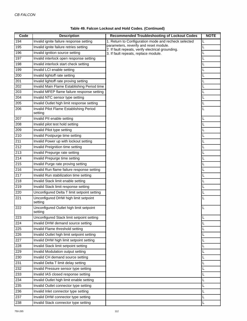
CB FALCON
750-265 112
194 Invalid ignite failure response setting 1. Return to Configuration mode and recheck selected parameters, reverify and reset module. 2. If fault repeats, verify electrical grounding. 3. If fault repeats, replace module.
L195 Invalid ignite failure retries setting L196 Invalid ignition source setting L197 Invalid interlock open response setting L198 Invalid interlock start check setting L199 Invalid LCI enable setting L200 Invalid lightoff rate setting L201 Invalid lightoff rate proving setting L202 Invalid Main Flame Establishing Period time L203 Invalid MFEP flame failure response setting L204 Invalid NTC sensor type setting L205 Invalid Outlet high limit response setting L206 Invalid Pilot Flame Establishing Period
settingL
207 Invalid PII enable setting L208 Invalid pilot test hold setting L209 Invalid Pilot type setting L210 Invalid Postpurge time setting L211 Invalid Power up with lockout setting L212 Invalid Preignition time setting L213 Invalid Prepurge rate setting L214 Invalid Prepurge time setting L215 Invalid Purge rate proving setting L216 Invalid Run flame failure response setting L217 Invalid Run stabilization time setting L218 Invalid Stack limit enable setting L219 Invalid Stack limit response setting L220 Unconfigured Delta T limit setpoint setting L221 Unconfigured DHW high limit setpoint
settingL
222 Unconfigured Outlet high limit setpoint setting
L
223 Unconfigured Stack limit setpoint setting L224 Invalid DHW demand source setting L225 Invalid Flame threshold setting L226 Invalid Outlet high limit setpoint setting L227 Invalid DHW high limit setpoint setting L228 Invalid Stack limit setpoint setting L229 Invalid Modulation output setting L230 Invalid CH demand source setting L231 Invalid Delta T limit delay setting L232 Invalid Pressure sensor type setting L233 Invalid IAS closed response setting L234 Invalid Outlet high limit enable setting L235 Invalid Outlet connector type setting L236 Invalid Inlet connector type setting L237 Invalid DHW connector type setting L238 Invalid Stack connector type setting L
Table 49. Falcon Lockout and Hold Codes. (Continued)
Code Description Recommended Troubleshooting of Lockout Codes NOTE

CB FALCON
113 750-265
239 Invalid S2 (J8-6) connector type setting L240 Invalid S5 (J8-11) connector type setting L241 Exchanger sensor not allowed with stack
connector settingL
242 Invalid DHW auto detect configuration L243 Invalid UV with spark interference not
compatible with Ignitor on throughout PFEPL
244 Internal fault: Safety relay test invalid state L245 Invalid Outlet connector type setting for T-
riseL
246 4-20mA cannot be used for both modulation and setpoint control
L
247 Invalid ILK bounce detection enable L248 Invalid forced recycle interval L249 STAT cannot be demand source when
Remote Stat is enabledL
250 Invalid Fan speed error response L251-255 RESERVED
Table 49. Falcon Lockout and Hold Codes. (Continued)
Code Description Recommended Troubleshooting of Lockout Codes NOTE
Table 50. Alerts.
Code DescriptionEE Management Faults
0 None (No alert)
1 Alert PCB was restored from factory defaults
2 Safety configuration parameters were restored
3 Configuration parameters were restored from
4 Invalid Factory Invisibility PCB was detected
5 Invalid Factory Range PCB was detected
6 Invalid range PCB record has been dropped
7 EEPROM lockout history was initialized
8 Switched application annunciation data blocks
9 Switched application configuration data blocks
10 Configuration was restored from factory defaults
11 Backup configuration settings was restored from
12 Annunciation configuration was restored from
13 Annunciation configuration was restored from
14 Safety group verification table was restored from
15 Safety group verification table was updated
16 Invalid Parameter PCB was detected
17 Invalid Range PCB was detected
System Parameter Errors
18 Alarm silence time exceeded maximum
19 Invalid safety group verification table was
20 Backdoor Password could not be determined.
21 Invalid safety group verification table was
22 CRC errors were found in application
23 Backup Alert PCB was restored from active one
24 RESERVED
25 Lead Lag operation switch was turned OFF
26 Lead Lag operation switch was turned ON
27 Safety processor was reset
28 Application processor was reset
29 Burner switch was turned OFF
30 Burner switch was turned ON
31 Program Module (PM) was inserted into socket
32 Program Module (PM) was removed from socket
33 Alert PCB was configured
34 Parameter PCB was configured
35 Range PCB was configured
36 Program Module (PM) incompatible with product
37 Program Module application parameter revision
38 Program Module safety parameter revision
39 PCB incompatible with product contained in
40 Parameter PCB in Program Module is too large
41 Range PCB in Program Module was too large for
42 Alert PCB in Program Module was too large for
43 IAS start check was forced on due to IAS
System Operation Faults
44 Low voltage was detected in safety processor
45 High line frequency occurred
Table 50. Alerts. (Continued)
Code Description

CB FALCON
750-265 114
46 Low line frequency occurred
47 Invalid subsystem reset request occurred
48 Write large enumerated Modbus register value
49 Maximum cycle count was reached
50 Maximum hours count was reached
51 Illegal Modbus write was attempted
52 Modbus write attempt was rejected (NOT
53 Illegal Modbus read was attempted
54 Safety processor brown-out reset occurred
55 Application processor watchdog reset occurred
56 Application processor brown-out reset occurred
57 Safety processor watchdog reset occurred
58 Alarm was reset by the user at the control
Demand/Rate Command Faults
59 Burner control firing rate was > absolute max
60 Burner control firing rate was < absolute min rate
61 Burner control firing rate was invalid, % vs. RPM
62 Burner control was firing with no fan request
63 Burner control rate (nonfiring) was > absolute
64 Burner control rate (nonfiring) was < absolute
65 Burner control rate (nonfiring) was absent
66 Burner control rate (nonfiring) was invalid, % vs.
67 Fan off cycle rate was invalid, % vs. RPM
68 Setpoint was overridden due to sensor fault
69 Modulation was overridden due to sensor fault
70 No demand source was set due to demand
71-73 RESERVED
Fan Parameter Errors
74 Periodic Forced Recycle
75 Absolute max fan speed was out of range
76 Absolute min fan speed was out of range
77 Fan gain down was invalid
78 Fan gain up was invalid
79 Fan minimum duty cycle was invalid
80 Fan pulses per revolution was invalid
81 Fan PWM frequency was invalid
82-83 RESERVED
Modulation Parameter Errors
84 Lead Lag CH 4-20mA water temperature setting
85 No Lead Lag add stage error threshold was
86 No Lead Lag add stage detection time was
87 No Lead Lag drop stage error threshold was
88 No Lead Lag drop stage detection time was
Table 50. Alerts. (Continued)
Code Description89 RESERVED
90 Modulation output type was invalid
91 Firing rate control parameter was invalid
92 Forced rate was out of range vs. min/max
93 Forced rate was invalid, % vs. RPM
94 Slow start ramp value was invalid
95 Slow start degrees value was invalid
96 Slow start was ended due to outlet sensor fault
97 Slow start was end due to reference setpoint
98 CH max modulation rate was invalid, % vs. RPM
99 CH max modulation rate was > absolute max
100 CH modulation range (max minus min) was too
101 DHW max modulation rate was invalid, % vs.
102 DHW max modulation rate was > absolute max
103 DHW modulation range (max minus min) was too
104 Min modulation rate was < absolute min rate
105 Min modulation rate was invalid, % vs. RPM
106 Manual rate was invalid, % vs. RPM
107 Slow start enabled, but forced rate was invalid
108 Analog output hysteresis was invalid
109 Analog modulation output type was invalid
110 IAS open rate differential was invalid
111 IAS open step rate was invalid
112 MIX max modulation rate was invalid, % vs. RPM
113 MIX max modulation rate was >absolute max or
114 MIX modulation range (max minus min) was too
Modulation Operation Faults
115 Fan was limited to its minimum duty cycle
116 Manual rate was > CH max modulation rate
117 Manual rate was > DHW max modulation rate
118 Manual rate was < min modulation rate
119 Manual rate in Standby was > absolute max rate
120 Modulation commanded rate was > CH max
121 Modulation commanded rate was > DHW max
122 Modulation commanded rate was < min
123 Modulation rate was limited due to outlet limit
124 Modulation rate was limited due to Delta-T limit
125 Modulation rate was limited due to stack limit
126 Modulation rate was limited due to
127 Fan Speed out of range in RUN
128 Modulation rate was limited due to IAS was open
129 Slow start ramp setting of zero will result in no
130 No forced rate was configured for slow start
Table 50. Alerts. (Continued)
Code Description
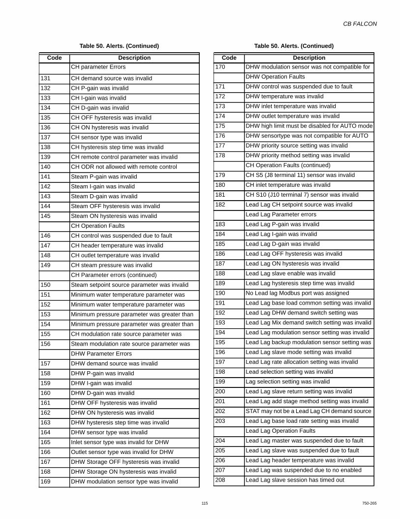
CB FALCON
115 750-265
CH parameter Errors
131 CH demand source was invalid
132 CH P-gain was invalid
133 CH I-gain was invalid
134 CH D-gain was invalid
135 CH OFF hysteresis was invalid
136 CH ON hysteresis was invalid
137 CH sensor type was invalid
138 CH hysteresis step time was invalid
139 CH remote control parameter was invalid
140 CH ODR not allowed with remote control
141 Steam P-gain was invalid
142 Steam I-gain was invalid
143 Steam D-gain was invalid
144 Steam OFF hysteresis was invalid
145 Steam ON hysteresis was invalid
CH Operation Faults
146 CH control was suspended due to fault
147 CH header temperature was invalid
148 CH outlet temperature was invalid
149 CH steam pressure was invalid
CH Parameter errors (continued)
150 Steam setpoint source parameter was invalid
151 Minimum water temperature parameter was
152 Minimum water temperature parameter was
153 Minimum pressure parameter was greater than
154 Minimum pressure parameter was greater than
155 CH modulation rate source parameter was
156 Steam modulation rate source parameter was
DHW Parameter Errors
157 DHW demand source was invalid
158 DHW P-gain was invalid
159 DHW I-gain was invalid
160 DHW D-gain was invalid
161 DHW OFF hysteresis was invalid
162 DHW ON hysteresis was invalid
163 DHW hysteresis step time was invalid
164 DHW sensor type was invalid
165 Inlet sensor type was invalid for DHW
166 Outlet sensor type was invalid for DHW
167 DHW Storage OFF hysteresis was invalid
168 DHW Storage ON hysteresis was invalid
169 DHW modulation sensor type was invalid
Table 50. Alerts. (Continued)
Code Description170 DHW modulation sensor was not compatible for
DHW Operation Faults
171 DHW control was suspended due to fault
172 DHW temperature was invalid
173 DHW inlet temperature was invalid
174 DHW outlet temperature was invalid
175 DHW high limit must be disabled for AUTO mode
176 DHW sensortype was not compatible for AUTO
177 DHW priority source setting was invalid
178 DHW priority method setting was invalid
CH Operation Faults (continued)
179 CH S5 (J8 terminal 11) sensor was invalid
180 CH inlet temperature was invalid
181 CH S10 (J10 terminal 7) sensor was invalid
182 Lead Lag CH setpoint source was invalid
Lead Lag Parameter errors
183 Lead Lag P-gain was invalid
184 Lead Lag I-gain was invalid
185 Lead Lag D-gain was invalid
186 Lead Lag OFF hysteresis was invalid
187 Lead Lag ON hysteresis was invalid
188 Lead Lag slave enable was invalid
189 Lead Lag hysteresis step time was invalid
190 No Lead lag Modbus port was assigned
191 Lead Lag base load common setting was invalid
192 Lead Lag DHW demand switch setting was
193 Lead Lag Mix demand switch setting was invalid
194 Lead Lag modulation sensor setting was invalid
195 Lead Lag backup modulation sensor setting was
196 Lead Lag slave mode setting was invalid
197 Lead Lag rate allocation setting was invalid
198 Lead selection setting was invalid
199 Lag selection setting was invalid
200 Lead Lag slave return setting was invalid
201 Lead Lag add stage method setting was invalid
202 STAT may not be a Lead Lag CH demand source
203 Lead Lag base load rate setting was invalid
Lead Lag Operation Faults
204 Lead Lag master was suspended due to fault
205 Lead Lag slave was suspended due to fault
206 Lead Lag header temperature was invalid
207 Lead Lag was suspended due to no enabled
208 Lead Lag slave session has timed out
Table 50. Alerts. (Continued)
Code Description
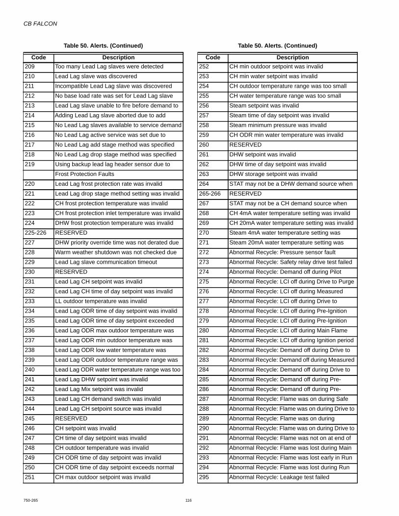
CB FALCON
750-265 116
209 Too many Lead Lag slaves were detected
210 Lead Lag slave was discovered
211 Incompatible Lead Lag slave was discovered
212 No base load rate was set for Lead Lag slave
213 Lead Lag slave unable to fire before demand to
214 Adding Lead Lag slave aborted due to add
215 No Lead Lag slaves available to service demand
216 No Lead Lag active service was set due to
217 No Lead Lag add stage method was specified
218 No Lead Lag drop stage method was specified
219 Using backup lead lag header sensor due to
Frost Protection Faults
220 Lead Lag frost protection rate was invalid
221 Lead Lag drop stage method setting was invalid
222 CH frost protection temperature was invalid
223 CH frost protection inlet temperature was invalid
224 DHW frost protection temperature was invalid
225-226 RESERVED
227 DHW priority override time was not derated due
228 Warm weather shutdown was not checked due
229 Lead Lag slave communication timeout
230 RESERVED
231 Lead Lag CH setpoint was invalid
232 Lead Lag CH time of day setpoint was invalid
233 LL outdoor temperature was invalid
234 Lead Lag ODR time of day setpoint was invalid
235 Lead Lag ODR time of day setpoint exceeded
236 Lead Lag ODR max outdoor temperature was
237 Lead Lag ODR min outdoor temperature was
238 Lead Lag ODR low water temperature was
239 Lead Lag ODR outdoor temperature range was
240 Lead Lag ODR water temperature range was too
241 Lead Lag DHW setpoint was invalid
242 Lead Lag Mix setpoint was invalid
243 Lead Lag CH demand switch was invalid
244 Lead Lag CH setpoint source was invalid
245 RESERVED
246 CH setpoint was invalid
247 CH time of day setpoint was invalid
248 CH outdoor temperature was invalid
249 CH ODR time of day setpoint was invalid
250 CH ODR time of day setpoint exceeds normal
251 CH max outdoor setpoint was invalid
Table 50. Alerts. (Continued)
Code Description252 CH min outdoor setpoint was invalid
253 CH min water setpoint was invalid
254 CH outdoor temperature range was too small
255 CH water temperature range was too small
256 Steam setpoint was invalid
257 Steam time of day setpoint was invalid
258 Steam minimum pressure was invalid
259 CH ODR min water temperature was invalid
260 RESERVED
261 DHW setpoint was invalid
262 DHW time of day setpoint was invalid
263 DHW storage setpoint was invalid
264 STAT may not be a DHW demand source when
265-266 RESERVED
267 STAT may not be a CH demand source when
268 CH 4mA water temperature setting was invalid
269 CH 20mA water temperature setting was invalid
270 Steam 4mA water temperature setting was
271 Steam 20mA water temperature setting was
272 Abnormal Recycle: Pressure sensor fault
273 Abnormal Recycle: Safety relay drive test failed
274 Abnormal Recycle: Demand off during Pilot
275 Abnormal Recycle: LCI off during Drive to Purge
276 Abnormal Recycle: LCI off during Measured
277 Abnormal Recycle: LCI off during Drive to
278 Abnormal Recycle: LCI off during Pre-Ignition
279 Abnormal Recycle: LCI off during Pre-Ignition
280 Abnormal Recycle: LCI off during Main Flame
281 Abnormal Recycle: LCI off during Ignition period
282 Abnormal Recycle: Demand off during Drive to
283 Abnormal Recycle: Demand off during Measured
284 Abnormal Recycle: Demand off during Drive to
285 Abnormal Recycle: Demand off during Pre-
286 Abnormal Recycle: Demand off during Pre-
287 Abnormal Recycle: Flame was on during Safe
288 Abnormal Recycle: Flame was on during Drive to
289 Abnormal Recycle: Flame was on during
290 Abnormal Recycle: Flame was on during Drive to
291 Abnormal Recycle: Flame was not on at end of
292 Abnormal Recycle: Flame was lost during Main
293 Abnormal Recycle: Flame was lost early in Run
294 Abnormal Recycle: Flame was lost during Run
295 Abnormal Recycle: Leakage test failed
Table 50. Alerts. (Continued)
Code Description
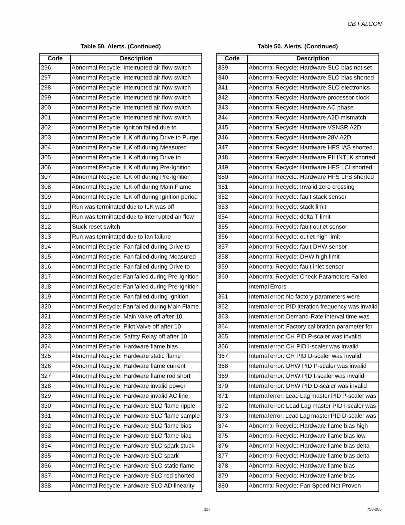
CB FALCON
117 750-265
296 Abnormal Recycle: Interrupted air flow switch
297 Abnormal Recycle: Interrupted air flow switch
298 Abnormal Recycle: Interrupted air flow switch
299 Abnormal Recycle: Interrupted air flow switch
300 Abnormal Recycle: Interrupted air flow switch
301 Abnormal Recycle: Interrupted air flow switch
302 Abnormal Recycle: Ignition failed due to
303 Abnormal Recycle: ILK off during Drive to Purge
304 Abnormal Recycle: ILK off during Measured
305 Abnormal Recycle: ILK off during Drive to
306 Abnormal Recycle: ILK off during Pre-Ignition
307 Abnormal Recycle: ILK off during Pre-Ignition
308 Abnormal Recycle: ILK off during Main Flame
309 Abnormal Recycle: ILK off during Ignition period
310 Run was terminated due to ILK was off
311 Run was terminated due to interrupted air flow
312 Stuck reset switch
313 Run was terminated due to fan failure
314 Abnormal Recycle: Fan failed during Drive to
315 Abnormal Recycle: Fan failed during Measured
316 Abnormal Recycle: Fan failed during Drive to
317 Abnormal Recycle: Fan failed during Pre-Ignition
318 Abnormal Recycle: Fan failed during Pre-Ignition
319 Abnormal Recycle: Fan failed during Ignition
320 Abnormal Recycle: Fan failed during Main Flame
321 Abnormal Recycle: Main Valve off after 10
322 Abnormal Recycle: Pilot Valve off after 10
323 Abnormal Recycle: Safety Relay off after 10
324 Abnormal Recycle: Hardware flame bias
325 Abnormal Recycle: Hardware static flame
326 Abnormal Recycle: Hardware flame current
327 Abnormal Recycle: Hardware flame rod short
328 Abnormal Recycle: Hardware invalid power
329 Abnormal Recycle: Hardware invalid AC line
330 Abnormal Recycle: Hardware SLO flame ripple
331 Abnormal Recycle: Hardware SLO flame sample
332 Abnormal Recycle: Hardware SLO flame bias
333 Abnormal Recycle: Hardware SLO flame bias
334 Abnormal Recycle: Hardware SLO spark stuck
335 Abnormal Recycle: Hardware SLO spark
336 Abnormal Recycle: Hardware SLO static flame
337 Abnormal Recycle: Hardware SLO rod shorted
338 Abnormal Recycle: Hardware SLO AD linearity
Table 50. Alerts. (Continued)
Code Description339 Abnormal Recycle: Hardware SLO bias not set
340 Abnormal Recycle: Hardware SLO bias shorted
341 Abnormal Recycle: Hardware SLO electronics
342 Abnormal Recycle: Hardware processor clock
343 Abnormal Recycle: Hardware AC phase
344 Abnormal Recycle: Hardware A2D mismatch
345 Abnormal Recycle: Hardware VSNSR A2D
346 Abnormal Recycle: Hardware 28V A2D
347 Abnormal Recycle: Hardware HFS IAS shorted
348 Abnormal Recycle: Hardware PII INTLK shorted
349 Abnormal Recycle: Hardware HFS LCI shorted
350 Abnormal Recycle: Hardware HFS LFS shorted
351 Abnormal Recycle: Invalid zero crossing
352 Abnormal Recycle: fault stack sensor
353 Abnormal Recycle: stack limit
354 Abnormal Recycle: delta T limit
355 Abnormal Recycle: fault outlet sensor
356 Abnormal Recycle: outlet high limit
357 Abnormal Recycle: fault DHW sensor
358 Abnormal Recycle: DHW high limit
359 Abnormal Recycle: fault inlet sensor
360 Abnormal Recycle: Check Parameters Failed
Internal Errors
361 Internal error: No factory parameters were
362 Internal error: PID iteration frequency was invalid
363 Internal error: Demand-Rate interval time was
364 Internal error: Factory calibration parameter for
365 Internal error: CH PID P-scaler was invalid
366 Internal error: CH PID I-scaler was invalid
367 Internal error: CH PID D-scaler was invalid
368 Internal error: DHW PID P-scaler was invalid
369 Internal error: DHW PID I-scaler was invalid
370 Internal error: DHW PID D-scaler was invalid
371 Internal error: Lead Lag master PID P-scaler was
372 Internal error: Lead Lag master PID I-scaler was
373 Internal error: Lead Lag master PID D-scaler was
374 Abnormal Recycle: Hardware flame bias high
375 Abnormal Recycle: Hardware flame bias low
376 Abnormal Recycle: Hardware flame bias delta
377 Abnormal Recycle: Hardware flame bias delta
378 Abnormal Recycle: Hardware flame bias
379 Abnormal Recycle: Hardware flame bias
380 Abnormal Recycle: Fan Speed Not Proven
Table 50. Alerts. (Continued)
Code Description

CB FALCON
750-265 118
381 Abnormal Recycle: Fan Speed Range Low
382 Abnormal Recycle: Fan Speed Range High
383-450 RESERVED
Circulator Errors
451 Circulator control was invalid
452 Circulator P-gain was invalid
453 Circulator I-gain was invalid
454 Circulator temperature was invalid
455 Circulator outlet temperature was invalid
456 Circulator inlet temperature was invalid
457 Circulator outdoor temperature was invalid
458 Circulator sensor choice was invalid
459 Circulator PID setpoint was invalid
Debug Faults
460 LCI lost in run
461 Abnormal Recycle: Demand lost in run from
462 Abnormal Recycle: Demand lost in run due to
463 Abnormal Recycle: Demand lost in run due to no
464 LCI lost in Combustion Pressure Establishing
465 LCI lost in Combustion Pressure Stabilization
466 RESERVED
Internal Data Faults
467 Internal error: EEPROM write was attempted
468 Internal error: EEPROM cycle count address
469 Internal error: EEPROM days count address was
470 Internal error: EEPROM hours count address
471 Internal error: Lockout record EEPROM index
472 Internal error: Request to write PM status was
473 Internal error: PM parameter address was invalid
474 Internal error: PM safety parameter address was
475 Internal error: Invalid record in lockout history
476 Internal error: EEPROM write buffer was full
477 Internal error: Data too large was not written to
478 Internal error: Safety key bit 0 was incorrect
479 Internal error: Safety key bit 1 was incorrect
480 Internal error: Safety key bit 2 was incorrect
481 Internal error: Safety key bit 3 was incorrect
482 Internal error: Safety key bit 4 was incorrect
483 Internal error: Safety key bit 5 was incorrect
484 Internal error: Safety key bit 6 was incorrect
485 Internal error: Safety key bit 7 was incorrect
486 Internal error: Safety key bit 8 was incorrect
487 Internal error: Safety key bit 9 was incorrect
Table 50. Alerts. (Continued)
Code Description488 Internal error: Safety key bit 10 was incorrect
489 Internal error: Safety key bit 11 was incorrect
490 Internal error: Safety key bit 12 was incorrect
491 Internal error: Safety key bit 13 was incorrect
492 Internal error: Safety key bit 14 was incorrect
493 Internal error: Safety key bit 15 was incorrect
494 Internal error: Safety relay timeout
495 Internal error: Safety relay commanded off
496 Internal error: Unknown safety error occurred
497 Internal error: Safety timer was corrupt
498 Internal error: Safety timer was expired
499 Internal error: Safety timings
500 Internal error: Safety shutdown
501 RESERVED
MIX Errors
502 Mix setpoint was invalid
503 Mix time of day setpoint was invalid
504 Mix outdoor temperature was invalid
505 Mix ODR time of day setpoint was invalid
506 Mix ODR time of day setpoint exceeds normal setpoint
507 Mix ODR max outdoor temperature was invalid508 Mix ODR min outdoor temperature was invalid509 Mix ODR low water temperature was invalid510 Mix ODR outdoor temperature range was invalid511 Mix ODR water temperature range was invalid512 Mix demand switch was invalid513 Mix ON hysteresis was invalid514 Mix OFF hysteresis was invalid515 Mix ODR min water temperature was invalid516 Mix hysteresis step time was invalid517 Mix P-gain was invalid518 Mix I-gain was invalid519 Mix D-gain was invalid520 Mix control was suspended due to fault521 Mix S10 (J10-7) temperature was invalid522 Mix outlet temperature was invalid523 Mix inlet temperature was invalid524 Mix S5 (J8-11) temperature was invalid525 Mix modulation sensor type was invalid526 Mix ODR min water temperature setpoint was
invalid527 Mix circulator sensor was invalid528 Mix flow control was invalid529 Mix temperature was invalid530 Mix sensor was invalid
Table 50. Alerts. (Continued)
Code Description
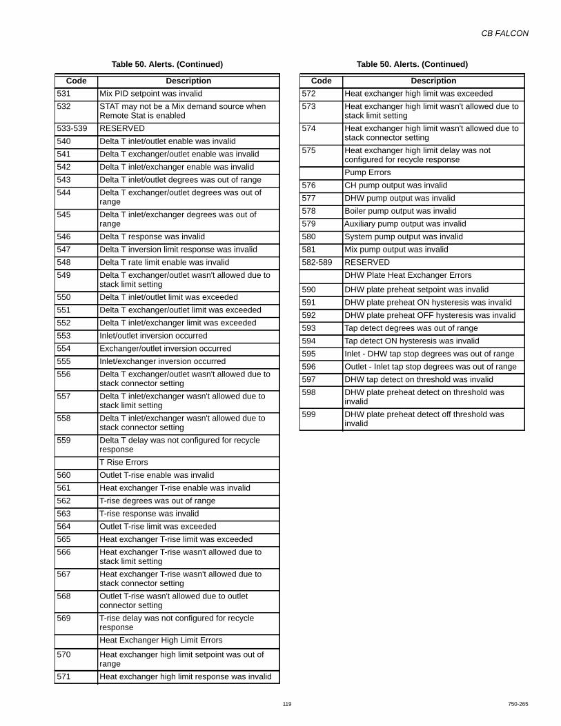
CB FALCON
119 750-265
531 Mix PID setpoint was invalid532 STAT may not be a Mix demand source when
Remote Stat is enabled533-539 RESERVED540 Delta T inlet/outlet enable was invalid541 Delta T exchanger/outlet enable was invalid542 Delta T inlet/exchanger enable was invalid543 Delta T inlet/outlet degrees was out of range544 Delta T exchanger/outlet degrees was out of
range545 Delta T inlet/exchanger degrees was out of
range546 Delta T response was invalid547 Delta T inversion limit response was invalid548 Delta T rate limit enable was invalid549 Delta T exchanger/outlet wasn't allowed due to
stack limit setting550 Delta T inlet/outlet limit was exceeded551 Delta T exchanger/outlet limit was exceeded552 Delta T inlet/exchanger limit was exceeded553 Inlet/outlet inversion occurred554 Exchanger/outlet inversion occurred555 Inlet/exchanger inversion occurred556 Delta T exchanger/outlet wasn't allowed due to
stack connector setting557 Delta T inlet/exchanger wasn't allowed due to
stack limit setting558 Delta T inlet/exchanger wasn't allowed due to
stack connector setting559 Delta T delay was not configured for recycle
responseT Rise Errors
560 Outlet T-rise enable was invalid561 Heat exchanger T-rise enable was invalid562 T-rise degrees was out of range563 T-rise response was invalid564 Outlet T-rise limit was exceeded565 Heat exchanger T-rise limit was exceeded566 Heat exchanger T-rise wasn't allowed due to
stack limit setting567 Heat exchanger T-rise wasn't allowed due to
stack connector setting568 Outlet T-rise wasn't allowed due to outlet
connector setting569 T-rise delay was not configured for recycle
responseHeat Exchanger High Limit Errors
570 Heat exchanger high limit setpoint was out of range
571 Heat exchanger high limit response was invalid
Table 50. Alerts. (Continued)
Code Description572 Heat exchanger high limit was exceeded573 Heat exchanger high limit wasn't allowed due to
stack limit setting574 Heat exchanger high limit wasn't allowed due to
stack connector setting575 Heat exchanger high limit delay was not
configured for recycle responsePump Errors
576 CH pump output was invalid577 DHW pump output was invalid578 Boiler pump output was invalid579 Auxiliary pump output was invalid580 System pump output was invalid581 Mix pump output was invalid582-589 RESERVED
DHW Plate Heat Exchanger Errors
590 DHW plate preheat setpoint was invalid591 DHW plate preheat ON hysteresis was invalid592 DHW plate preheat OFF hysteresis was invalid593 Tap detect degrees was out of range594 Tap detect ON hysteresis was invalid595 Inlet - DHW tap stop degrees was out of range596 Outlet - Inlet tap stop degrees was out of range597 DHW tap detect on threshold was invalid598 DHW plate preheat detect on threshold was
invalid599 DHW plate preheat detect off threshold was
invalid
Table 50. Alerts. (Continued)
Code Description

CB FALCON
750-265 120

APPENDIX B
Falcon Display/Operator Interface

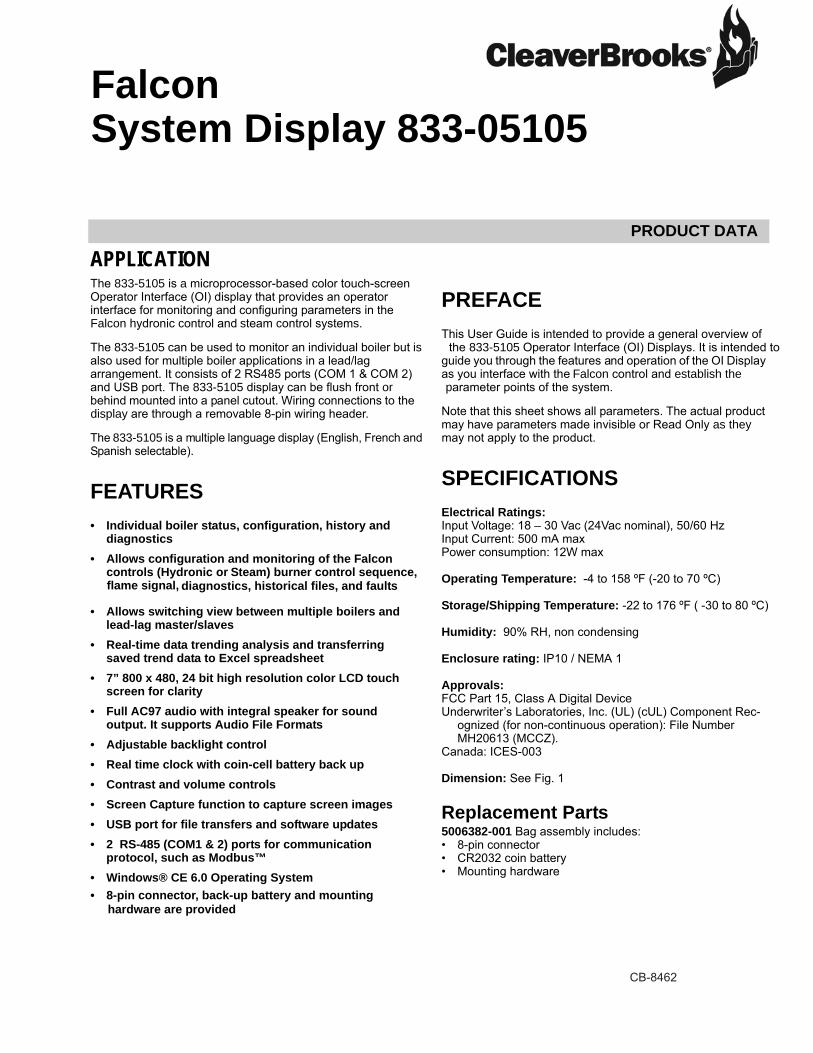
PRODUCT DATA
CB-8462
APPLICATION
Operator Interface (OI) display that provides an operator interface for monitoring and configuring parameters in the
also used for multiple boiler applications in a lead/lag
behind mounted into a panel cutout. Wiring connections to the
FEATURES• Individual boiler status, configuration, history and
diagnostics
• Allows switching view between multiple boilers and lead-lag master/slaves
• Real-time data trending analysis and transferring saved trend data to Excel spreadsheet
• 7” 800 x 480, 24 bit high resolution color LCD touch screen for clarity
• Full AC97 audio with integral speaker for sound output. It supports Audio File Formats
• Adjustable backlight control• Real time clock with coin-cell battery back up• Contrast and volume controls• Screen Capture function to capture screen images• USB port for file transfers and software updates• 2 RS-485 (COM1 & 2) ports for communication
protocol, such as Modbus™• Windows® CE 6.0 Operating System• 8-pin connector, back-up battery and mounting
hardware are provided
PREFACEThis User Guide is intended to provide a general overview of
guide you through the features and operation of the OI Display
Note that this sheet shows all parameters. The actual product
SPECIFICATIONSElectrical Ratings:Input Voltage: 18 – 30 Vac (24Vac nominal), 50/60 HzInput Current: 500 mA maxPower consumption: 12W max
Operating Temperature: -4 to 158 ºF (-20 to 70 ºC)
Storage/Shipping Temperature: -22 to 176 ºF ( -30 to 80 ºC)
Humidity: 90% RH, non condensing
Enclosure rating: IP10 / NEMA 1
Approvals:FCC Part 15, Class A Digital Device Underwriter’s Laboratories, Inc. (UL) (cUL) Component Rec-
ognized (for non-continuous operation): File Number MH20613 (MCCZ).
Canada: ICES-003
Dimension: See Fig. 1
Replacement Parts5006382-001 Bag assembly includes:• 8-pin connector• CR2032 coin battery• Mounting hardware
FalconSystem Display 833-05105
Falcon hydronic control and steam control systems.
The 833-5105 is a microprocessor-based color touch-screen
display are through a removable 8-pin wiring header.
The 833-5105 is a multiple language display (English, French and Spanish selectable).
arrangement. It consists of 2 RS485 ports (COM 1 & COM 2) as you interface with the Falcon control and establish theand USB port. The 833-5105 display can be flush front or parameter points of the system.
• Allows configuration and monitoring of the Falcon controls (Hydronic or Steam) burner control sequence,flame signal, diagnostics, historical files, and faults
The 833-5105 can be used to monitor an individual boiler but is the 833-5105 Operator Interface (OI) Displays. It is intended to
may have parameters made invisible or Read Only as they may not apply to the product.
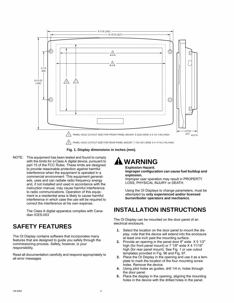
NOTE: This equipment has been tested and found to comply with the limits for a Class A digital device, pursuant to part 15 of the FCC Rules. These limits are designed to provide reasonable protection against harmful interference when the equipment is operated in a commercial environment. This equipment generat-eds, uses and can radiate radio frequency energy and, if not installed and used in accordance with the instruction manual, may cause harmful interference to radio communications. Operation of this equip-ment is a residential area is likely to cause harmful interference in which case the use will be required to correct the interference at his own expense.
The Class A digital apparatus complies with Cana-dian ICES-003
SAFETY FEATURESThe OI Display contains software that incorporates many features that are designed to guide you safely through the commissioning process. Safety, however, is your responsibility.
Read all documentation carefully and respond appropriately to all error messages
WARNINGExplosion Hazard.Improper configuration can cause fuel buildup and explosion.Improper user operation may result in PROPERTY LOSS, PHYSICAL INJURY or DEATH.
Using the OI Displays to change parameters, must be attempted by only experienced and/or licensed burner/boiler operators and mechanics.
INSTALLATION INSTRUCTIONSThe OI Display can be mounted on the door panel of an electrical enclosure.
1. Select the location on the door panel to mount the dis-play; note that the device will extend into the enclosure at least one inch past the mounting surface.
2. Provide an opening in the panel door 8" wide X 5 1/2" high (for front panel mount) or 7 1/8" wide X 4 11/16" high (for rear panel mount). See Fig. 1 or use cutout templates provided in Fig. 96 and Fig. 97.
3. Place the OI Display in the opening and use it as a tem-plate to mark the location of the four mounting screw holes. Remove the device.
4. Using pilot holes as guides, drill 1/4 in. holes through the door panel.
5. Place the display in the opening, aligning the mounting holes in the device with the drilled holes in the panel.
6-21/32(169)
9-7/16 (240)
1-27/32 (47)
M32735PANEL HOLE CUTOUT SIZE FOR FRONT PANEL MOUNT: 8 (203) WIDE X 5-1/2 (140) HIGH.1
PANEL HOLE CUTOUT SIZE FOR REAR PANEL MOUNT: 7-1/8 (181) WIDE X 4-11/16 (119) HIGH.2
1
1
8-15/16 (227)
3-1/2(89)
2
2
Fig. 1. Display dimensions in inches (mm).
CB-8462 2
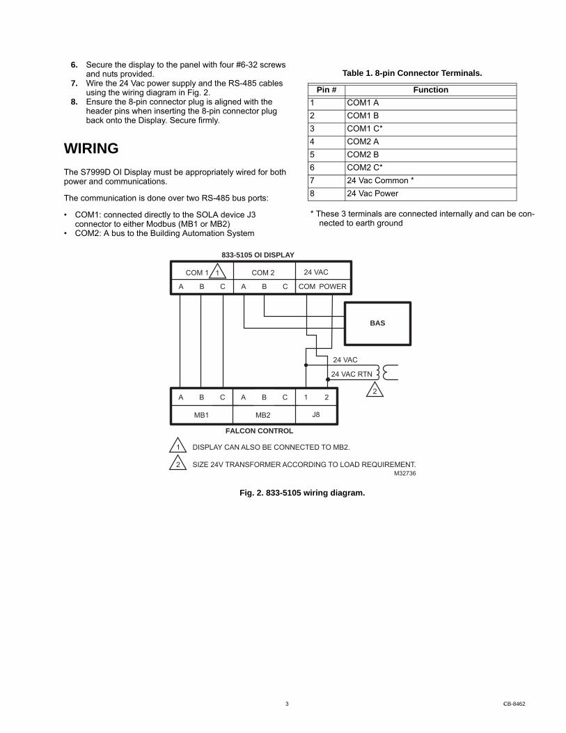
6. Secure the display to the panel with four #6-32 screws and nuts provided.
7. Wire the 24 Vac power supply and the RS-485 cables using the wiring diagram in Fig. 2.
8. Ensure the 8-pin connector plug is aligned with the header pins when inserting the 8-pin connector plug back onto the Display. Secure firmly.
WIRINGThe S7999D OI Display must be appropriately wired for both power and communications.
The communication is done over two RS-485 bus ports:
• COM1: connected directly to the SOLA device J3 connector to either Modbus (MB1 or MB2)
• COM2: A bus to the Building Automation System
* These 3 terminals are connected internally and can be con-nected to earth ground
Table 1. 8-pin Connector Terminals.
Pin # Function1 COM1 A2 COM1 B3 COM1 C*4 COM2 A5 COM2 B6 COM2 C*7 24 Vac Common *8 24 Vac Power
M32736
DISPLAY CAN ALSO BE CONNECTED TO MB2.
SIZE 24V TRANSFORMER ACCORDING TO LOAD REQUIREMENT.
2CBACBA 1
J8MB1 MB2
BAS
1
1
2
2
POWERCBACBA COM
24 VACCOM 1 COM 2
24 VAC RTN
24 VAC
833-5105 OI DISPLAY
FALCON CONTROL
Fig. 2. 833-5105 wiring diagram.
3 -CB-8462
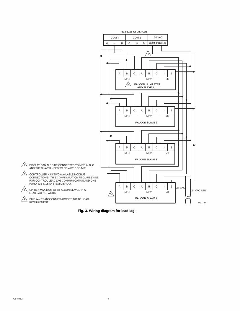
M32737
DISPLAY CAN ALSO BE CONNECTED TO MB2; A, B, C
CONTROLLER HAS TWO AVAILABLE MODBUS CONNECTIONS: THIS CONFIGURATION REQUIRES ONE FOR CONTROL LEAD LAG COMMUNICATION AND ONE
LEAD LAG NETWORK.
SIZE 24V TRANSFORMER ACCORDING TO LOAD REQUIREMENT.
AND SLAVE 1
2CBACBA 1
J8MB1 MB2
2CBACBA 1
J8MB1 MB2
2CBACBA 1
J8MB1 MB2
2CBACBA 1
J8MB1 MB23
1
2
2
4
3
1
POWERCBACBA COM
24 VACCOM 1 COM 2
24 VAC RTN24 VAC
833-5105 OI DISPLAY
FALCON LL MASTER
FALCON SLAVE 2
FALCON SLAVE 3
FALCON SLAVE 4
UP TO A MAXIMUM OF 8 FALCON SLAVES IN A
FOR A 833-5105 SYSTEM DISPLAY.
AND THE SLAVES NEED TO BE WIRED TO MB1.
Fig. 3. Wiring diagram for lead lag.
CB-8462 4

BUILDING AUTOMATION SYSTEM (BAS) CONFIGURATION
as defined in Fig. 4.
BAS Modbus message timeout should be set to 1.0 seconds or higher. This means it could take up to 1.0 seconds (max) for the System Display to reply to a BAS message.
Retries: BAS must setup retries upon timeout to ensure the Modbus request is accepted.
BAS Modbus poll rate should be set to 1.0 seconds. This means that the BAS should wait for a minimum of 1.0 seconds after receiving a Modbus message from Sola before sending a new Modbus message.
QUICK SETUP
aligned and pressed firmly in place.2. Make sure the wires between the 8-pin connector and
the controller are properly wired and secured.3. Make sure the power supply is connected securely to
the power source.
WARNINGElectrical Shock Hazard.Can cause severe injury, death or equipment damage.Line voltage is present at the 120 Vac power supply.
STARTING THE S7999D OI DISPLAY
Power-up ValidationThe Home page will appear when the device is properly powered. Select the Setup button to adjust contrast and sound as desired. It the screen is dim, check Pin 7 and 8 wiring connections.
A “camera” icon on the left top corner is for screen snapshot use. Up to 16 snapshots can be stored in the display and can be copied to an USB memory stick.
Home pageMake sure a screen similar to Fig. 5 appears after the OI Display has completely powered up.
M32738
UP TO 8
BAS
COM 2
COM 1
COM 2
COM 1
COM 2
COM 1
1
1
1 2 3 4 5
833-5105 833-5105 833-5105
FALCON FALCON FALCON FALCON FALCON
FALCONS
EACH FALCON IN THE BAS WILL HAVE A DIFFERENT MODBUS ADDRESS.
Fig. 4. 833-5105 in a Building Automation System.
and ensure all devices have unique Modbus addresses Connect the BAS Modbus wiring to COM2 of the 833-5105
1. Make sure the 833-5105 8-pin connector is properly
Fig. 5. Home page (Boiler 1 in normal operation).
5 CB-8462
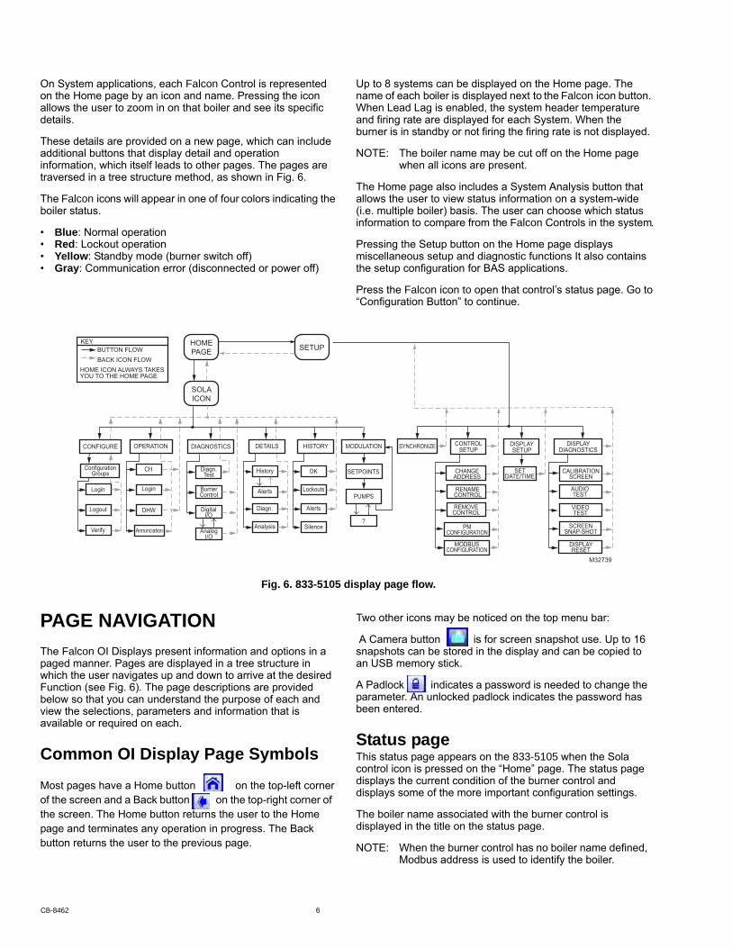
on the Home page by an icon and name. Pressing the icon allows the user to zoom in on that boiler and see its specific details.
These details are provided on a new page, which can include additional buttons that display detail and operation information, which itself leads to other pages. The pages are traversed in a tree structure method, as shown in Fig. 6.
boiler status.
• Blue: Normal operation• Red: Lockout operation• Yellow: Standby mode (burner switch off)• Gray: Communication error (disconnected or power off)
Up to 8 systems can be displayed on the Home page. The
When Lead Lag is enabled, the system header temperature and firing rate are displayed for each System. When the burner is in standby or not firing the firing rate is not displayed.
NOTE: The boiler name may be cut off on the Home page when all icons are present.
The Home page also includes a System Analysis button that allows the user to view status information on a system-wide (i.e. multiple boiler) basis. The user can choose which status
Pressing the Setup button on the Home page displays miscellaneous setup and diagnostic functions It also contains the setup configuration for BAS applications.
“Configuration Button” to continue.
PAGE NAVIGATION
paged manner. Pages are displayed in a tree structure in which the user navigates up and down to arrive at the desired Function (see Fig. 6). The page descriptions are provided below so that you can understand the purpose of each and view the selections, parameters and information that is available or required on each.
Common OI Display Page Symbols
Most pages have a Home button on the top-left cornerof the screen and a Back button on the top-right corner of the screen. The Home button returns the user to the Home page and terminates any operation in progress. The Back button returns the user to the previous page.
Two other icons may be noticed on the top menu bar:
A Camera button is for screen snapshot use. Up to 16 snapshots can be stored in the display and can be copied to an USB memory stick.
A Padlock indicates a password is needed to change the parameter. An unlocked padlock indicates the password has been entered.
Status pagecontrol icon is pressed on the “Home” page. The status page displays the current condition of the burner control and displays some of the more important configuration settings.
The boiler name associated with the burner control is displayed in the title on the status page.
NOTE: When the burner control has no boiler name defined, Modbus address is used to identify the boiler.
HOMEPAGE
SOLAICON
M32739
SETUP
SYNCHRONIZE DISPLAYSETUP
CONTROLSETUP
DISPLAYDIAGNOSTICSCONFIGURE
ConfigurationGroups
Login
Logout
Verify
OPERATION
CH
Login
DHW
Annunciation
DIAGNOSTICS
Diagn.Test
BurnerControl
DigitalI/O
AnalogI/O
DETAILS
History
Alerts
Diagn.
Analysis
HISTORY
OK
Lockouts
Alerts
Silence
MODULATION
?
SETPOINTS
PUMPS
KEY BUTTON FLOW BACK ICON FLOWHOME ICON ALWAYS TAKES YOU TO THE HOME PAGE
CHANGEADDRESS
SETDATE/TIME
RENAMECONTROL
REMOVECONTROL
PMCONFIGURATION
MODBUSCONFIGURATION
CALIBRATIONSCREEN
AUDIOTEST
VIDEOTEST
SCREENSNAP-SHOT
DISPLAYRESET
On System applications, each Falcon Control is represented
The Falcon icons will appear in one of four colors indicating the
name of each boiler is displayed next to the Falcon icon button.
information to compare from the Falcon Controls in the system.
Press the Falcon icon to open that control’s status page. Go to
Fig. 6. 833-5105 display page flow.
The Falcon OI Displays present information and options in a
This status page appears on the 833-5105 when the Sola
CB-8462 6

The initial status page displayed contains summary status information as shown in Fig. 7. Any status information not applicable for the installation is grayed/blanked out on the screen.
Buttons on this screen include: • Configure: used to configure the burner control (see
“Configure Button” for more details). • Operation: used to perform daily or frequent functions with
the burner control, such as setpoint adjustment, etc. (see “Operation Button” for details).
• Diagnostic: used to view burner control diagnostic information (see “Diagnostics Button” for more details).
• Details: used to view burner control detail status information (see “Details Button” for more details).
Fig. 7. Status page.
Configure ButtonThe configuration page allows the user to view and set
The configuration page contains a menu of parameters grouped into functional areas that the user selects for configuration (see Fig. 8). See Table 59 for all parameters
Fig. 8. Configuration menu page.
No specific order for configuration is required. All parameters are enabled for editing, though some may not be applicable (e.g., a configuration parameter may disable a control feature). Selecting a parameter group from the menu displays parameters exclusively applicable for the functional group on the page (see Fig. 9). These parameters can be edited, and when the user is finished, control returns back to the configuration menu page.
Hydronic control.
Each parameter is displayed in its group. If there are more parameters than will fit on the screen, a vertical scroll bar allows the user to scroll up and down to view all parameters. The parameter name is displayed on the left and the current setting is displayed in the text box on the right.
Configuration Password Some parameters require a valid configuration password be entered by the user before the parameter can be changed. The password need only be entered once while the user remains on the configuration pages. Leaving the configuration pages ends the scope of the password.
permitted. Each access level has defined rights when interfacing with configuration and status parameters within the controls.
• End user: The end user can read or view the control parameters and be allowed to change some operating parameters, CH setpoint as an example.
• Installer: The installer can read all control parameters and
is used to customize the control for a particular installation.• OEM: The OEM can read and change all parameters,
change sensor limits and burner control safety parameters.
level. The end user level requires no password, but the installer and OEM levels have unique passwords defined for them.
Control after logging in with the current password. When the password is changed, it is saved for all future logins.
Fig. 9. Sample configuration page for the Falcon
parameters that define how the connected Falcon functions in the (hydronic or steam) heating system.
available for configuration (some parameters may not be visible).
change allowed parameters. This access level
Three levels of access to Falcon Control parameters are
The installer and OEM passwords can be changed in the Falcon
Different passwords exist in the Falcon Control for each access
7 CB-8462
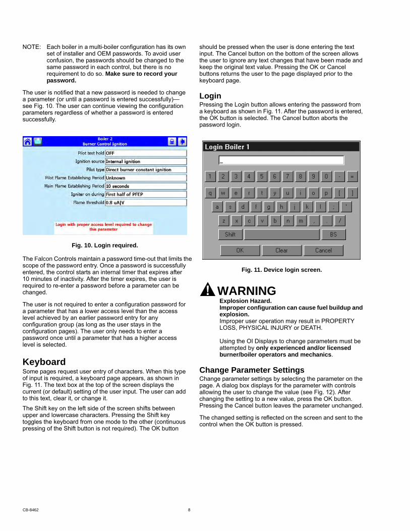
NOTE: Each boiler in a multi-boiler configuration has its own set of installer and OEM passwords. To avoid user confusion, the passwords should be changed to the same password in each control, but there is no requirement to do so. Make sure to record your password.
The user is notified that a new password is needed to change a parameter (or until a password is entered successfully)—see Fig. 10. The user can continue viewing the configuration parameters regardless of whether a password is entered successfully.
Fig. 10. Login required.
scope of the password entry. Once a password is successfully entered, the control starts an internal timer that expires after 10 minutes of inactivity. After the timer expires, the user is required to re-enter a password before a parameter can be changed.
The user is not required to enter a configuration password for a parameter that has a lower access level than the access level achieved by an earlier password entry for any configuration group (as long as the user stays in the configuration pages). The user only needs to enter a password once until a parameter that has a higher access level is selected.
KeyboardSome pages request user entry of characters. When this type of input is required, a keyboard page appears, as shown in Fig. 11. The text box at the top of the screen displays the current (or default) setting of the user input. The user can add to this text, clear it, or change it.
The Shift key on the left side of the screen shifts between upper and lowercase characters. Pressing the Shift key toggles the keyboard from one mode to the other (continuous pressing of the Shift button is not required). The OK button
should be pressed when the user is done entering the text input. The Cancel button on the bottom of the screen allows the user to ignore any text changes that have been made and keep the original text value. Pressing the OK or Cancel buttons returns the user to the page displayed prior to the keyboard page.
LoginPressing the Login button allows entering the password from a keyboard as shown in Fig. 11. After the password is entered, the OK button is selected. The Cancel button aborts the password login.
Fig. 11. Device login screen.
WARNINGExplosion Hazard.Improper configuration can cause fuel buildup and explosion.Improper user operation may result in PROPERTY LOSS, PHYSICAL INJURY or DEATH.
Using the OI Displays to change parameters must be attempted by only experienced and/or licensed burner/boiler operators and mechanics.
Change Parameter SettingsChange parameter settings by selecting the parameter on the page. A dialog box displays for the parameter with controls allowing the user to change the value (see Fig. 12). After changing the setting to a new value, press the OK button. Pressing the Cancel button leaves the parameter unchanged.
The changed setting is reflected on the screen and sent to the control when the OK button is pressed.
The Falcon Controls maintain a password time-out that limits the
CB-8462 8
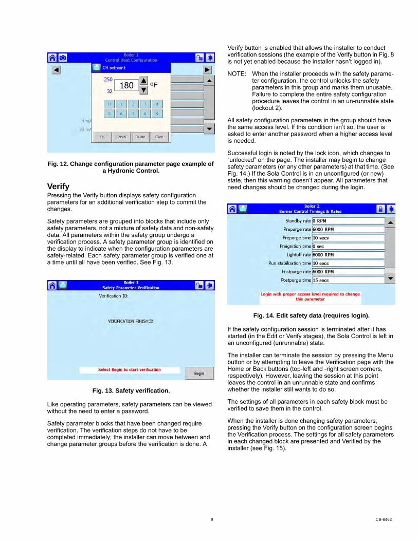
Fig. 12. Change configuration parameter page example of a Hydronic Control.
VerifyPressing the Verify button displays safety configuration parameters for an additional verification step to commit the changes.
Safety parameters are grouped into blocks that include only safety parameters, not a mixture of safety data and non-safety data. All parameters within the safety group undergo a verification process. A safety parameter group is identified on the display to indicate when the configuration parameters are safety-related. Each safety parameter group is verified one at a time until all have been verified. See Fig. 13.
Fig. 13. Safety verification.
Like operating parameters, safety parameters can be viewed without the need to enter a password.
Safety parameter blocks that have been changed require verification. The verification steps do not have to be completed immediately; the installer can move between and change parameter groups before the verification is done. A
Verify button is enabled that allows the installer to conduct verification sessions (the example of the Verify button in Fig. 8 is not yet enabled because the installer hasn’t logged in).
NOTE: When the installer proceeds with the safety parame-ter configuration, the control unlocks the safety parameters in this group and marks them unusable. Failure to complete the entire safety configuration procedure leaves the control in an un-runnable state (lockout 2).
All safety configuration parameters in the group should have the same access level. If this condition isn’t so, the user is asked to enter another password when a higher access level is needed.
Successful login is noted by the lock icon, which changes to “unlocked” on the page. The installer may begin to change safety parameters (or any other parameters) at that time. (See Fig. 14.) If the Sola Control is in an unconfigured (or new) state, then this warning doesn’t appear. All parameters that need changes should be changed during the login.
Fig. 14. Edit safety data (requires login).
If the safety configuration session is terminated after it has started (in the Edit or Verify stages), the Sola Control is left in an unconfigured (unrunnable) state.
The installer can terminate the session by pressing the Menu button or by attempting to leave the Verification page with the Home or Back buttons (top-left and -right screen corners, respectively). However, leaving the session at this point leaves the control in an unrunnable state and confirms whether the installer still wants to do so.
The settings of all parameters in each safety block must be verified to save them in the control.
When the installer is done changing safety parameters, pressing the Verify button on the configuration screen begins the Verification process. The settings for all safety parameters in each changed block are presented and Verified by the installer (see Fig. 15).
9 CB-8462
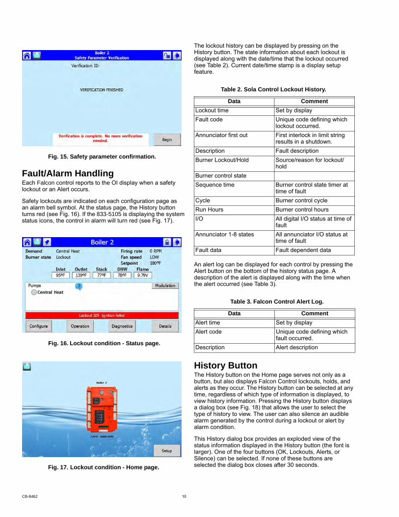
Fig. 15. Safety parameter confirmation.
Fault/Alarm Handlinglockout or an Alert occurs.
Safety lockouts are indicated on each configuration page as an alarm bell symbol. At the status page, the History button
status icons, the control in alarm will turn red (see Fig. 17).
The lockout history can be displayed by pressing on the History button. The state information about each lockout is displayed along with the date/time that the lockout occurred (see Table 2). Current date/time stamp is a display setup feature.
An alert log can be displayed for each control by pressing the Alert button on the bottom of the history status page. A description of the alert is displayed along with the time when the alert occurred (see Table 3).
History ButtonThe History button on the Home page serves not only as a
alerts as they occur. The History button can be selected at any time, regardless of which type of information is displayed, to view history information. Pressing the History button displays a dialog box (see Fig. 18) that allows the user to select the type of history to view. The user can also silence an audible alarm generated by the control during a lockout or alert by alarm condition.
This History dialog box provides an exploded view of the status information displayed in the History button (the font is larger). One of the four buttons (OK, Lockouts, Alerts, or Silence) can be selected. If none of these buttons are selected the dialog box closes after 30 seconds.
Table 2. Sola Control Lockout History.
Data CommentLockout time Set by displayFault code Unique code defining which
lockout occurred.Annunciator first out First interlock in limit string
results in a shutdown.Description Fault descriptionBurner Lockout/Hold Source/reason for lockout/
holdBurner control stateSequence time Burner control state timer at
time of faultCycle Burner control cycleRun Hours Burner control hoursI/O All digital I/O status at time of
faultAnnunciator 1-8 states All annunciator I/O status at
time of faultFault data Fault dependent data
Data CommentAlert time Set by displayAlert code Unique code defining which
fault occurred.Description Alert description
button, but also displays Falcon Control lockouts, holds, and
Each Falcon control reports to the OI display when a safety
turns red (see Fig. 16). If the 833-5105 is displaying the system
Table 3. Falcon Control Alert Log.
Fig. 16. Lockout condition - Status page.
Fig. 17. Lockout condition - Home page.
CB-8462 10
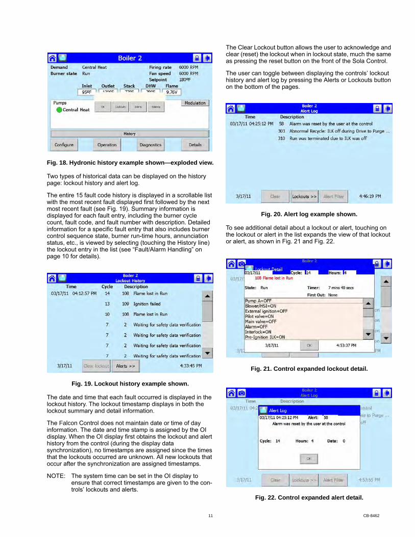
Fig. 18. Hydronic history example shown—exploded view.
Two types of historical data can be displayed on the history page: lockout history and alert log.
The entire 15 fault code history is displayed in a scrollable list with the most recent fault displayed first followed by the next most recent fault (see Fig. 19). Summary information is displayed for each fault entry, including the burner cycle count, fault code, and fault number with description. Detailed information for a specific fault entry that also includes burner control sequence state, burner run-time hours, annunciation status, etc., is viewed by selecting (touching the History line) the lockout entry in the list (see “Fault/Alarm Handling” on page 10 for details).
Fig. 19. Lockout history example shown.
The date and time that each fault occurred is displayed in the lockout history. The lockout timestamp displays in both the lockout summary and detail information.
information. The date and time stamp is assigned by the OI display. When the OI display first obtains the lockout and alert history from the control (during the display data synchronization), no timestamps are assigned since the times that the lockouts occurred are unknown. All new lockouts that occur after the synchronization are assigned timestamps.
NOTE: The system time can be set in the OI display to ensure that correct timestamps are given to the con-trols’ lockouts and alerts.
The Clear Lockout button allows the user to acknowledge and clear (reset) the lockout when in lockout state, much the same as pressing the reset button on the front of the Sola Control.
The user can toggle between displaying the controls’ lockout history and alert log by pressing the Alerts or Lockouts button on the bottom of the pages.
Fig. 20. Alert log example shown.
To see additional detail about a lockout or alert, touching on the lockout or alert in the list expands the view of that lockout or alert, as shown in Fig. 21 and Fig. 22.
Fig. 21. Control expanded lockout detail.
Fig. 22. Control expanded alert detail.
The Falcon Control does not maintain date or time of day
11 CB-8462
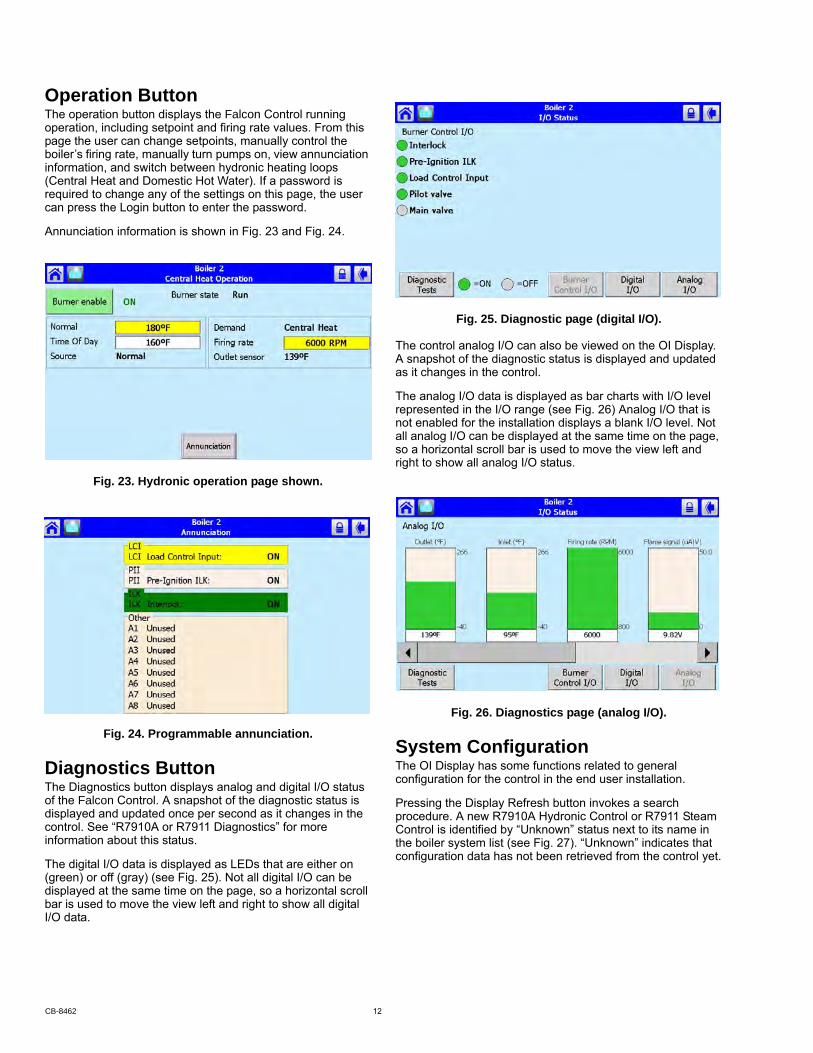
Operation Buttonoperation, including setpoint and firing rate values. From this page the user can change setpoints, manually control the boiler’s firing rate, manually turn pumps on, view annunciation information, and switch between hydronic heating loops (Central Heat and Domestic Hot Water). If a password is required to change any of the settings on this page, the user can press the Login button to enter the password.
Annunciation information is shown in Fig. 23 and Fig. 24.
Fig. 23. Hydronic operation page shown.
Fig. 24. Programmable annunciation.
Diagnostics ButtonThe Diagnostics button displays analog and digital I/O status
displayed and updated once per second as it changes in the control. See “R7910A or R7911 Diagnostics” for more information about this status.
The digital I/O data is displayed as LEDs that are either on (green) or off (gray) (see Fig. 25). Not all digital I/O can be displayed at the same time on the page, so a horizontal scroll bar is used to move the view left and right to show all digital I/O data.
Fig. 25. Diagnostic page (digital I/O).
The control analog I/O can also be viewed on the OI Display. A snapshot of the diagnostic status is displayed and updated as it changes in the control.
The analog I/O data is displayed as bar charts with I/O level represented in the I/O range (see Fig. 26) Analog I/O that is not enabled for the installation displays a blank I/O level. Not all analog I/O can be displayed at the same time on the page, so a horizontal scroll bar is used to move the view left and right to show all analog I/O status.
Fig. 26. Diagnostics page (analog I/O).
System ConfigurationThe OI Display has some functions related to general configuration for the control in the end user installation.
Pressing the Display Refresh button invokes a search procedure. A new R7910A Hydronic Control or R7911 Steam Control is identified by “Unknown” status next to its name in the boiler system list (see Fig. 27). “Unknown” indicates that configuration data has not been retrieved from the control yet.
The operation button displays the Falcon Control running
of the Falcon Control. A snapshot of the diagnostic status is
CB-8462 12

Fig. 27. System refresh and synchronize screen.
The control connected to the Modbus network is indicated to the user after the search procedure has concluded.
Once the control is located it must be synchronized with the OI Display before it can be displayed. New controls are not displayed on the Home page until this synchronization (see below) is performed.
System SynchronizationThe user can manually synchronize configuration data from the connected controls at any time.
A new control is visible when configuration and status data is gathered from it. This collection procedure takes a few minutes. The control is marked as “Unknown” when no configuration information exists. Normally, control configuration data collection only needs to be performed when the control is initially installed. However, a re synchronization is necessary after the OI Display is reset.
The user presses the Synchronize button to begin synchronization with the control. See Fig. 27.
ConfigurationThe SOLA Control can be configured from the OI Display. The control configuration is grouped into the functional groups seen in Table 4.
Most of this configuration is performed by either the contractor/installer or at Honeywell. Each functional group is displayed on the Configuration menu page.
Parameters in functional groups that are not applicable for the installation can be ignored. In some cases, features in a functional group are disabled by default and are enabled when needed for the installation.
R7910A HYDRONIC CONTROL, R7911 STEAM CONTROL CONFIGURATION PARAMETERSThe following pages list the configuration parameters available for the R7910A or R7911 installed.
NOTE: Individual Configuration pages may differ from this text as features are added or amended by Honey-well.
A password is required to make changes to the Configuration Parameters. The SOLA Control will be in a Lockout 2 “waiting for safety data verification” as received or will go to a Lockout 2 when changes are made to the safety data.
Table 4. Functional Configuration Groups.
Hydronic Control Steam ControlSystem Identification and Access
Steam Identification and Access
CH - Central Heat Steam ConfigurationOutdoor Reset Modulation ConfigurationDHW - Domestic Hot Water Pump ConfigurationDHW StorageDHW PlateWarm Weather ShutdownDemand Priority
Modulation Configuration Statistics ConfigurationPump Configuration Stack LimitStatistics Configuration Annunciation ConfigurationHigh Limit Burner Control InterlocksStack Limit Burner control Timings and
RatesDelta T LimitsT-Rise LimitHeat Exchanger High LimitAnti-condensation Burner Control Flame Failure Frost Protection Configuration
System Configuration
Annunciation Configuration Fan Configuration Burner Control Interlocks Lead Lag ConfigurationBurner Control Timings and Rates Burner Control IgnitionBurner Control Flame FailureSystem ConfigurationFan Configuration Sensor ConfigurationLead Lag Slave ConfigurationLead Lag Master Configuration
Table 4. Functional Configuration Groups.
Hydronic Control Steam Control
13 CB-8462
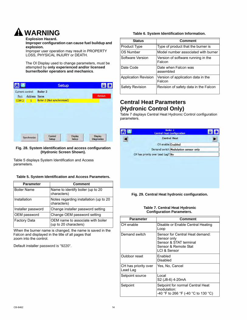
WARNINGExplosion Hazard.Improper configuration can cause fuel buildup and explosion.Improper user operation may result in PROPERTY LOSS, PHYSICAL INJURY or DEATH.
The OI Display used to change parameters, must be attempted by only experienced and/or licensed burner/boiler operators and mechanics.
Fig. 28. System identification and access configuration (Hydronic Screen Shown).
Table 5 displays System Identification and Access parameters.
When the burner name is changed, the name is saved in the
zoom into the control.
Central Heat Parameters
Table 7 displays Central Heat Hydronic Control configuration parameters.
Fig. 29. Central Heat hydronic configuration.
Table 5. System Identification and Access Parameters.
Parameter CommentBoiler Name Name to identify boiler (up to 20
characters)Installation Notes regarding installation (up to 20
characters)Installer password Change installer password settingOEM password Change OEM password settingFactory Data OEM name to associate with boiler
(up to 20 characters)
Table 6. System Identification Information.
Status CommentProduct Type Type of product that the burner isOS Number Model number associated with burnerSoftware Version Version of software running in the
assembledApplication Revision Version of application data in the
Table 7. Central Heat Hydronic Configuration Parameters.
Parameter CommentCH enable Disable or Enable Central Heating
LoopDemand switch Sensor for Central Heat demand:
Sensor onlySensor & STAT terminalSensor & Remote StatLCI & Sensor
Outdoor reset EnabledDisabled
CH has priority over Lead Lag
Yes, No, Cancel
Setpoint source LocalS2 (J8-6) 4-20mA
Setpoint Setpoint for normal Central Heat modulation:-40 °F to 266 °F (-40 °C to 130 °C)
(Hydronic Control Only)
FalconDate Code Date when Falcon was
FalconSafety Revision Revision of safety data in the Falcon
Falcon and displayed in the title of all pages that
Default installer password is "9220".
CB-8462 14

Outdoor Reset Parameters
Table 9 displays Outdoor Reset configuration parameters. Pressing the left or right arrow displays Lead Lag, which lists the same parameters.
Fig. 30. Outdoor reset configuration.
Domestic Hot Water (DHW) Configuration Parameters
Table 10 displays Domestic Hot Water (DHW) configuration parameters.
Time of day setpoint Setpoint when Time Of Day switch is on. -40 °F to 266 °F (-40 °C to 130 °C)
Off hysteresis Differential above setpoint when boiler is turned off.32 °F to 266 °F (0 °C to 130 °C)
On hysteresis Differential from setpoint when boiler is turned on. 32 °F to 266 °F (0 °C to 130 °C)
4 mA water temperature
-40 °F to 266 °F (-40 °C to 130 °C)
20 mA water temperature
-40 °F to 266 °F (-40 °C to 130 °C)
Modulation sensor Outlet sensor, Inlet sensor, S5 (J8-11)Modulation Rate Sensor
Local
P-gain Gain applied for the P portion of the PID equation0-400
I-gain Gain applied for the I portion of the PID equation0-400
D-gain Gain applied for the D portion of the PID equation0-400
Hysteresis step time Time between hysteresis step changes: 0-600 seconds (0=Disable hysteresis stepping)
Table 8. Steam Configuration Parameters
Parameter CommentSteam enable Disable/enable steam feature Steam demand source
Sensor and LCISensor and Remote StatSensor and Stat TerminalSensor Only
Steam pressure setpoint
Setpoint for normal modulationAdjustable 0 to 15 or 0 to 150 (sensor dependant)
Steam time of day setpoint
Setpoint when TOD switch on Adjustable 0 to 15 or 0 to 150 (sensor dependant)
Minimum steam pressure
Establishes setpoint for the 4ma. input. Adjustable 0 to 15 or 0 to 150 (sensor dependant)
Steam pressure off hysteresis
Differential below setpoint when boiler is turned offAdjustable 0 to 15 or 0 to 150 (sensor dependant)
Steam pressure on hysteresis
Differential from setpoint when boileris turned on.Adjustable 0 to 15 or 0 to 150 (sensor dependant)
Steam hysteresis step time
Time between hysteresis changes 0 to 600 seconds (0=disable)
Table 7. Central Heat Hydronic Configuration Parameters. (Continued)
Parameter Comment Steam P Gain Gain applied for the P portion of thePID equation0-400
Steam I Gain Gain applied for the I portion of the PID Equation - 0-400
Steam D Gain Gain applied for the D portion of thePID equation0-400
Steam 4-20 ma remote control
uses 4-20ma remote control function to control either the setpoint or modulation for Steam Disable, setpoint, modulation
Table 9. Outdoor Reset Configuration Parameters.
Parameter CommentMaximum outdoor temperature
-40 °F to 266 °F (-40 °C to 130 °C)
Minimum outdoor temperature
-40 °F to 266 °F (-40 °C to 130 °C)
Low water temperature
-40 °F to 266 °F (-40 °C to 130 °C)
Minimum water temperature
-40 °F to 266 °F (-40 °C to 130 °C)
Maximum off point -40 °F to 266 °F (-40 °C to 130 °C)
Table 8. Steam Configuration Parameters
Parameter Comment
(Hydronic Control Only)
(Hydronic Control Only)
15 CB-8462
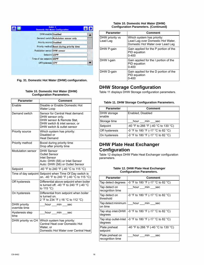
Fig. 31. Domestic Hot Water (DHW) configuration.
DHW Storage ConfigurationTable 11 displays DHW Storage configuration parameters.
DHW Plate Heat Exchanger ConfigurationTable 12 displays DHW Plate Heat Exchanger configuration parameters.
Table 10. Domestic Hot Water (DHW)Configuration Parameters.
Parameter CommentEnable Disable or Enable Domestic Hot
Water LoopDemand switch Sensor for Central Heat demand:
DHW sensor only,DHW sensor & Remote Stat,DHW switch & inlet sensor, orDHW switch & outlet sensor
Priority source Which system has priority:Disabled orHeat Demand
Priority method Boost during priority timeDrop after priority time
Modulation sensor DHW SensorOutlet SensorInlet SensorAuto: DHW (S6) or Inlet SensorAuto: DHW (S6) or Outlet Sensor
Setpoint -40 °F to 240 °F (-40 °C to 115 °C)Time of day setpoint Setpoint when Time Of Day switch is
on. -40 °F to 240 °F (-40 °C to 115 °C)Off hysteresis Differential above setpoint when boiler
is turned off. -40 °F to 240 °F (-40 °C to 115 °C)
On hysteresis Differential from setpoint when boiler is turned on. 2 °F to 234 °F (-16 °C to 112 °C)
DHW priority override time
___hour ___min ___sec
Hysteresis step time
___hour ___min ___sec
DHW priority vs CH Which system has priority:Central Heat over Domestic Hot Water, or Domestic Hot Water over Central Heat
DHW priority vs Lead Lag
Which system has priority:Lead Lag over Domestic Hot Water,Domestic Hot Water over Lead Lag
DHW P-gain Gain applied for the P portion of the PID equation0-400
DHW I-gain Gain applied for the I portion of the PID equation0-400
DHW D-gain Gain applied for the D portion of the PID equation0-400
Table 11. DHW Storage Configuration Parameters.
Parameter CommentDHW storage enable
Enabled, Disabled
Storage time ___hour ___min ___secSetpoint -40 °F to 266 °F (-40 °C to 130 °C)Off hysteresis -0 °F to 180 °F (-17 °C to 82 °C)On hysteresis -0 °F to 180 °F (-17 °C to 82 °C)
Table 12. DHW Plate Heat Exchanger Configuration Parameters.
Parameter CommentTap detect degrees -0 °F to 180 °F (-17 °C to 82 °C)Tap detect on recognition time
___hour ___min ___sec
Tap detect on threshold
-0 °F to 180 °F (-17 °C to 82 °C)
Tap detect minimum on time
___hour ___min ___sec
Tap stop inlet-DHW degrees
-0 °F to 180 °F (-17 °C to 82 °C)
Tap stop outlet-Inlet degrees
-0 °F to 180 °F (-17 °C to 82 °C)
Plate preheat setpoint
-40 °F to 266 °F (-40 °C to 130 °C)
Plate preheat on recognition time
___hour ___min ___sec
Table 10. Domestic Hot Water (DHW)Configuration Parameters. (Continued)
Parameter Comment
CB-8462 16

Warm Weather Shutdown ConfigurationTable 13 displays Warm Weather Setpoint configuration parameters.
Demand Priority Configuration ParametersFig. 32 displays R7910A Hydronic Control Demand Priority configuration options. Press the arrows to change the priority order.
Fig. 32. Demand priority configuration.
Plate preheat on hysteresis
-0 °F to 180 °F (-17 °C to 82 °C)
Plate preheat off hysteresis
-0 °F to 180 °F (-17 °C to 82 °C)
Plate preheat detect on threshold
-0 °F to 180 °F (-17 °C to 82 °C)
Plate preheat detect off threshold
-0 °F to 180 °F (-17 °C to 82 °C)
Plate preheat minimum on time
___hour ___min ___sec
Plate preheat delay after tap
___hour ___min ___sec
Table 13. Warm Weather Setpoint Configuration Parameters.
Parameter CommentEnable Enabled, disabledSetpoint -40 °F to 266 °F (-40 °C to 130 °C)
Table 12. DHW Plate Heat Exchanger Configuration Parameters. (Continued)
Parameter Comment
17 CB-8462

Modulation Configuration Parametersconfiguration parameters.
Fig. 33. Modulation configuration.
Steam Modulation Configuration Parametersparameters.
Table 14. R7910A Hydronic Control Modulation Configura-tion Parameters.
Parameter CommentCH maximum modulation rate
RPM or %
DHW maximum modulation rate
RPM or %
Minimum modulation rate
RPM or %
CH forced rate time 0-600 secondsCH forced rate RPM or %
DHW forced rate time 0-600 secondsDHW forced rate RPM or %CH slow start enable Enabled
DisabledDHW slow start enable
EnabledDisabled
Slow start degrees -40 °F to 266 °F (-40 °C to 130 °C)Slow start ramp RPM /minute or %/minute0-10/4-20 mA Output hysteresis
Table 15. R7911 Steam Modulation Configuration Parameters.
Parameter CommentCH maximum modulation rate
RPM or %
Minimum modulation rate
RPM or %
CH forced rate time 0-600 secondsCH forced rate RPM or %0-10/4-20 mA Output hysteresis
Table 14. R7910A Hydronic Control Modulation Configura-tion Parameters. (Continued)
Parameter CommentTable 14 displays Hydronic Control Modulation
Table 15 displays Steam Modulation Configuration
CB-8462 18
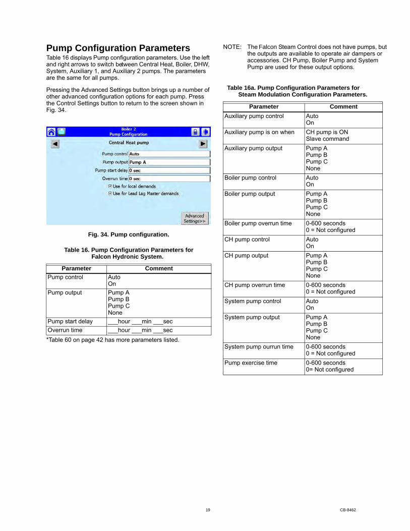
Pump Configuration ParametersTable 16 displays Pump configuration parameters. Use the left and right arrows to switch between Central Heat, Boiler, DHW, System, Auxiliary 1, and Auxiliary 2 pumps. The parameters are the same for all pumps.
Pressing the Advanced Settings button brings up a number of other advanced configuration options for each pump. Press the Control Settings button to return to the screen shown in Fig. 34.
Fig. 34. Pump configuration.
*Table 60 on page 42 has more parameters listed.
the outputs are available to operate air dampers or accessories. CH Pump, Boiler Pump and System Pump are used for these output options.
Table 16. Pump Configuration Parameters for
Parameter CommentPump control Auto
OnPump output Pump A
Pump BPump CNone
Pump start delay ___hour ___min ___secOverrun time ___hour ___min ___sec
Steam Modulation Configuration Parameters.
Parameter CommentAuxiliary pump control Auto
OnAuxiliary pump is on when CH pump is ON
Slave commandAuxiliary pump output Pump A
Pump BPump CNone
Boiler pump control AutoOn
Boiler pump output Pump APump BPump CNone
Boiler pump overrun time 0-600 seconds0 = Not configured
CH pump control Auto On
CH pump output Pump APump BPump CNone
CH pump overrun time 0-600 seconds0 = Not configured
System pump control AutoOn
System pump output Pump APump BPump CNone
System pump ourrun time 0-600 seconds0 = Not configured
Pump exercise time 0-600 seconds0= Not configured
NOTE: The Falcon Steam Control does not have pumps, but
Table 16a. Pump Configuration Parameters for
Falcon Hydronic System.
19 CB-8462
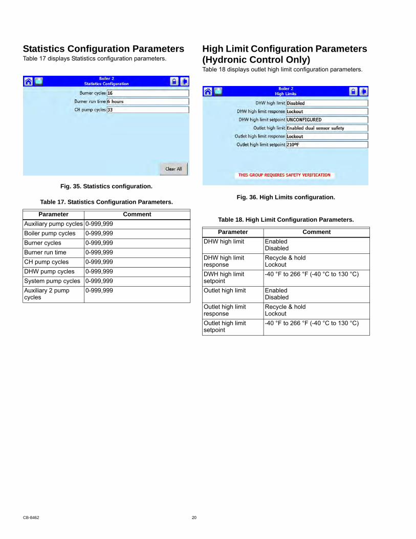
Statistics Configuration ParametersTable 17 displays Statistics configuration parameters.
Fig. 35. Statistics configuration.
High Limit Configuration Parameters
Table 18 displays outlet high limit configuration parameters.
Fig. 36. High Limits configuration.Table 17. Statistics Configuration Parameters.
Parameter CommentAuxiliary pump cycles 0-999,999Boiler pump cycles 0-999,999Burner cycles 0-999,999Burner run time 0-999,999CH pump cycles 0-999,999DHW pump cycles 0-999,999System pump cycles 0-999,999Auxiliary 2 pump cycles
0-999,999
Table 18. High Limit Configuration Parameters.
Parameter CommentDHW high limit Enabled
DisabledDHW high limit response
Recycle & holdLockout
DWH high limit setpoint
-40 °F to 266 °F (-40 °C to 130 °C)
Outlet high limit Enabled Disabled
Outlet high limit response
Recycle & holdLockout
Outlet high limit setpoint
-40 °F to 266 °F (-40 °C to 130 °C)
(Hydronic Control Only)
CB-8462 20

Stack Limit Configuration ParametersTable 19 displays stack limit configuration parameters.
Fig. 37. Stack Limit configuration.
Delta T Limit Configuration Parameters
Table 20 displays other limit parameters. Use the left and right arrows to switch between Inlet to Outlet Flow and Exchanger to Outlet Flow. The parameters are the same for all pumps.
Fig. 38. Delta T Limit configuration.Table 19. Stack Limit Configuration Parameters.
Parameter CommentStack limit Enabled dual sensor safety
Enabled single sensor non safetyDisabled
Stack limit delay ___hour ___min ___secStack limit response Lockout
Recycle & delayStack limit setpoint 32 °F to 266 °F (0 °C to 130 °C)
Table 20. Delta T Limit Configuration Parameters.
Parameter CommentDelta T enable Enabled
DisabledDelta T degrees 0 °F to 234 °F (-17 °C to 112 °C)Delta T delay ___hour ___min ___secDelta T response Recycle & delay
Recycle & Delay with retry limitLockout
Delta T retry limit 0–100Delta T rate limit enable
EnabledDisabled
Delta T inverse limit time
___hour ___min ___sec
Delta T inverse limit response
Recycle & delayRecycle & delay with retry limitLockout
(Hydronic Control Only)
21 CB-8462
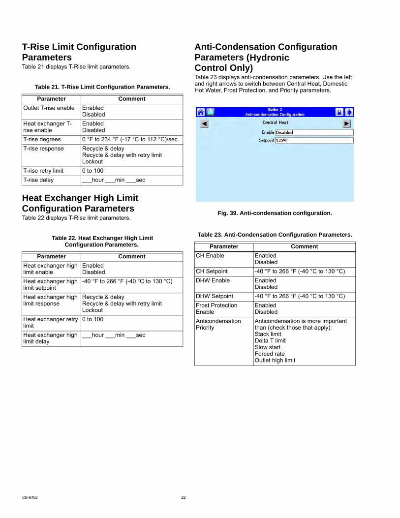
T-Rise Limit Configuration
Table 21 displays T-Rise limit parameters.
Heat Exchanger High Limit Configuration ParametersTable 22 displays T-Rise limit parameters.
Anti-Condensation Configuration
Control Only)Table 23 displays anti-condensation parameters. Use the left and right arrows to switch between Central Heat, Domestic Hot Water, Frost Protection, and Priority parameters.
Fig. 39. Anti-condensation configuration.
Table 21. T-Rise Limit Configuration Parameters.
Parameter CommentOutlet T-rise enable Enabled
DisabledHeat exchanger T-rise enable
EnabledDisabled
T-rise degrees 0 °F to 234 °F (-17 °C to 112 °C)/secT-rise response Recycle & delay
Recycle & delay with retry limitLockout
T-rise retry limit 0 to 100T-rise delay ___hour ___min ___sec
Table 22. Heat Exchanger High Limit Configuration Parameters.
Parameter CommentHeat exchanger high limit enable
EnabledDisabled
Heat exchanger high limit setpoint
-40 °F to 266 °F (-40 °C to 130 °C)
Heat exchanger high limit response
Recycle & delayRecycle & delay with retry limitLockout
Heat exchanger retry limit
0 to 100
Heat exchanger high limit delay
___hour ___min ___sec
Table 23. Anti-Condensation Configuration Parameters.
Parameter CommentCH Enable Enabled
DisabledCH Setpoint -40 °F to 266 °F (-40 °C to 130 °C)DHW Enable Enabled
DisabledDHW Setpoint -40 °F to 266 °F (-40 °C to 130 °C)Frost Protection Enable
EnabledDisabled
Anticondensation Priority
Anticondensation is more important than (check those that apply):Stack limitDelta T limitSlow startForced rateOutlet high limit
Hydronic Parameters Parameters (
CB-8462 22
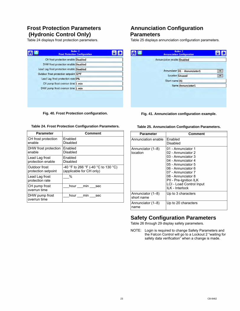
Frost Protection Parameters
Table 24 displays frost protection parameters.
Fig. 40. Frost Protection configuration.
Annunciation Configuration
Table 25 displays annunciation configuration parameters.
Fig. 41. Annunciation configuration example.
Safety Configuration ParametersTable 26 through 29 display safety parameters.
NOTE: Login is required to change Safety Parameters and
safety data verification” when a change is made.
Table 24. Frost Protection Configuration Parameters.
Parameter CommentCH frost protection enable
EnabledDisabled
DHW frost protection enable
EnabledDisabled
Lead Lag frost protection enable
EnabledDisabled
Outdoor frost protection setpoint
-40 °F to 266 °F (-40 °C to 130 °C) (applicable for CH only)
Lead Lag frost protection rate
___%
CH pump frost overrun time
___hour ___min ___sec
DHW pump frost overrun time
___hour ___min ___sec
Table 25. Annunciation Configuration Parameters.
Parameter CommentAnnunciation enable Enabled
DisabledAnnunciator (1–8) location
01 - Annunciator 102 - Annunciator 203 - Annunciator 304 - Annunciator 405 - Annunciator 506 - Annunciator 607 - Annunciator 708 - Annunciator 8PII - Pre-Ignition ILKLCI - Load Control InputILK - Interlock
Annunciator (1–8) short name
Up to 3 characters
Annunciator (1–8) name
Up to 20 characters
(Hydronic Control Only) Parameters
the Falcon Control will go to a Lockout 2 “waiting for
23 CB-8462

Fig. 42. Burner Control Interlocks control.
Fig. 43. Burner Control Timings and Rates configuration.
Fig. 44. Burner Control Ignition configuration.
Table 26. Burner ControlInterlocks Configuration.
Parameter CommentPII enable Enabled
DisabledLCI enable Enabled
DisabledInterrupted air switch (IAS) enable
Enable during purge and ignitionDisabledEnable during purge
Interlock (ILK) start check enable
No ILK checkILK check
ILK/IAS open response
RecycleLockout
ILK bounce detection enable
EnabledDisabled
Purge rate proving Fan SpeedHigh Fire SwitchNone
Lightoff rate proving Fan SpeedLow Fire SwitchNone
Table 27. Burner Control Timings and Rates Configura-tion.
Parameter CommentPrepurge rate RPM or %Prepurge time ___hour ___min ___secRun stabilization time ___hour ___min ___secStandby Rate RPM or %Postpurge rate RPM or %Postpurge time ___hour ___min ___secForced recycle interval time
___day ___hour ___min
Table 28. Burner Control Ignition Configuration.
Parameter CommentPilot test hold On
OffIgnition source Hot Surface Igniter
External ignitionInternal ignition
Pilot type Direct burner constant ignitionDirect burner pulsed ignitionIntermittentInterrupted
Lightoff rate RPM or %Preignition time ___hour ___min ___secPilot Flame Establishing Period
15 secs10 secs4 secs
Igniter on during 1st half of PFEPPilot Flame Establishing Period
Main Flame Establishing Period
15 secs10 secs5 secs
Flame Threshold A/V
CB-8462 24
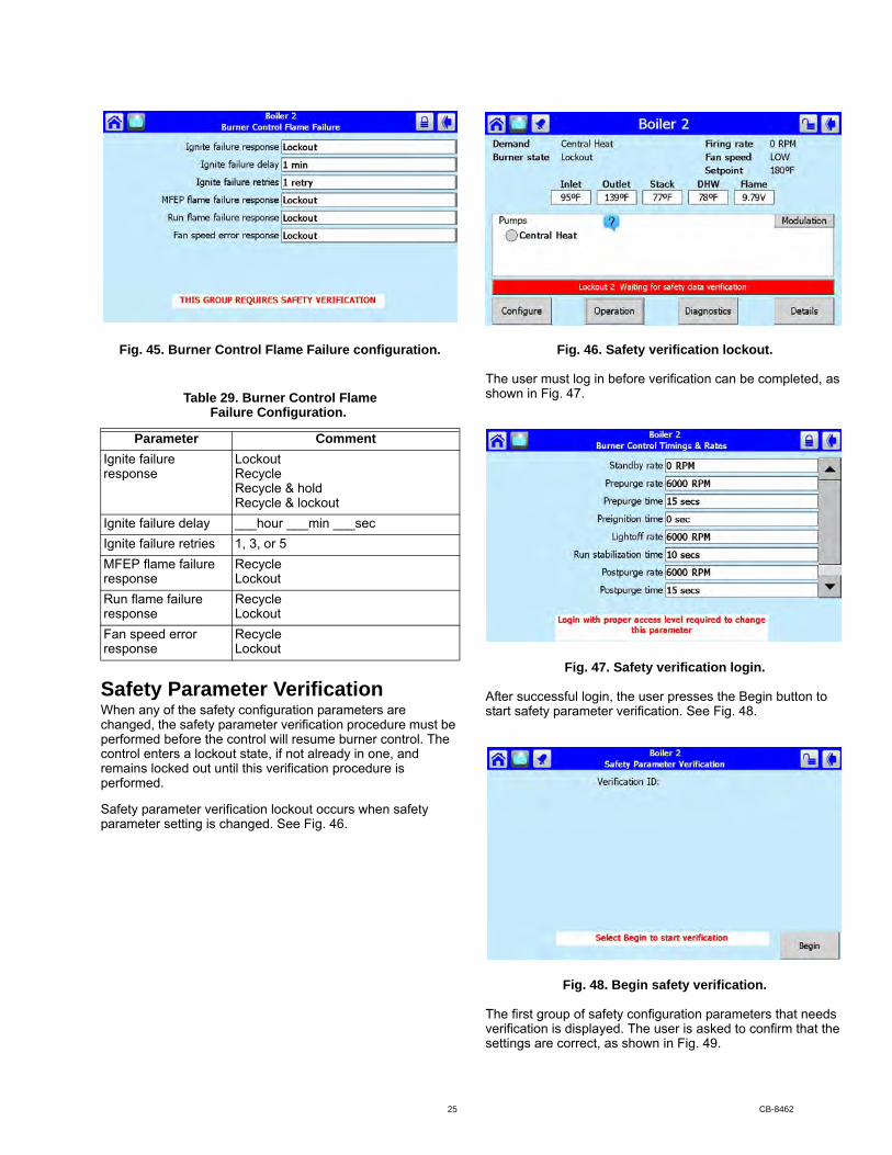
Fig. 45. Burner Control Flame Failure configuration.
Safety Parameter VerificationWhen any of the safety configuration parameters are changed, the safety parameter verification procedure must be performed before the control will resume burner control. The control enters a lockout state, if not already in one, and remains locked out until this verification procedure is performed.
Safety parameter verification lockout occurs when safety parameter setting is changed. See Fig. 46.
Fig. 46. Safety verification lockout.
The user must log in before verification can be completed, as shown in Fig. 47.
Fig. 47. Safety verification login.
After successful login, the user presses the Begin button to start safety parameter verification. See Fig. 48.
Fig. 48. Begin safety verification.
The first group of safety configuration parameters that needs verification is displayed. The user is asked to confirm that the settings are correct, as shown in Fig. 49.
Table 29. Burner Control Flame Failure Configuration.
Parameter CommentIgnite failure response
LockoutRecycleRecycle & holdRecycle & lockout
Ignite failure delay ___hour ___min ___secIgnite failure retries 1, 3, or 5MFEP flame failure response
RecycleLockout
Run flame failure response
RecycleLockout
Fan speed error response
RecycleLockout
25 CB-8462
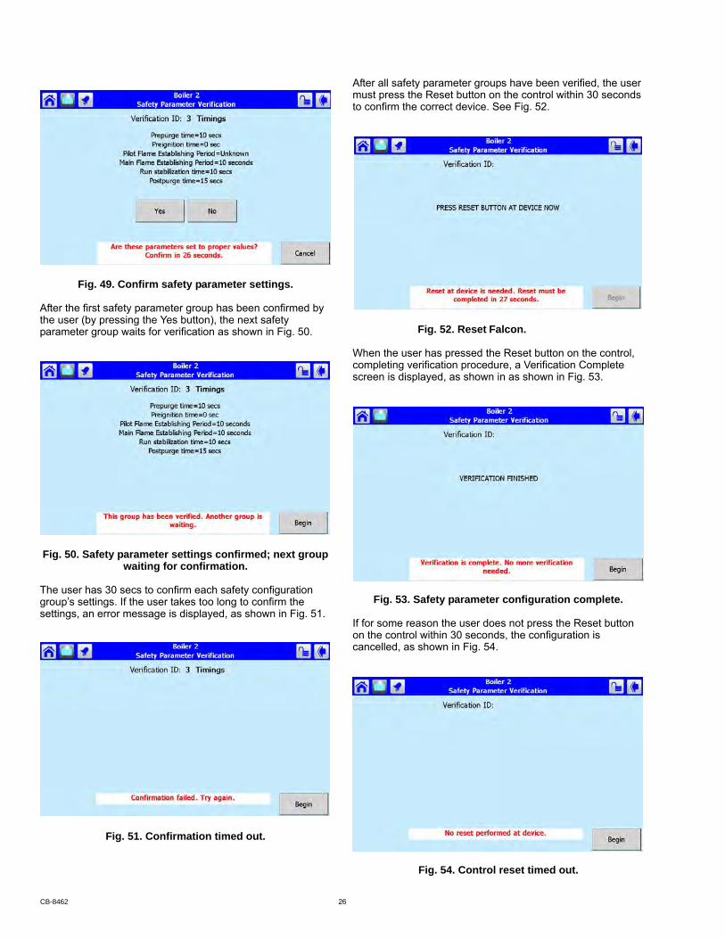
Fig. 49. Confirm safety parameter settings.
After the first safety parameter group has been confirmed by the user (by pressing the Yes button), the next safety parameter group waits for verification as shown in Fig. 50.
Fig. 50. Safety parameter settings confirmed; next group waiting for confirmation.
The user has 30 secs to confirm each safety configuration group’s settings. If the user takes too long to confirm the settings, an error message is displayed, as shown in Fig. 51.
Fig. 51. Confirmation timed out.
After all safety parameter groups have been verified, the user must press the Reset button on the control within 30 seconds to confirm the correct device. See Fig. 52.
When the user has pressed the Reset button on the control, completing verification procedure, a Verification Complete screen is displayed, as shown in as shown in Fig. 53.
Fig. 53. Safety parameter configuration complete.
If for some reason the user does not press the Reset button on the control within 30 seconds, the configuration is cancelled, as shown in Fig. 54.
Fig. 54. Control reset timed out.
Fig. 52. Reset Falcon.
CB-8462 26
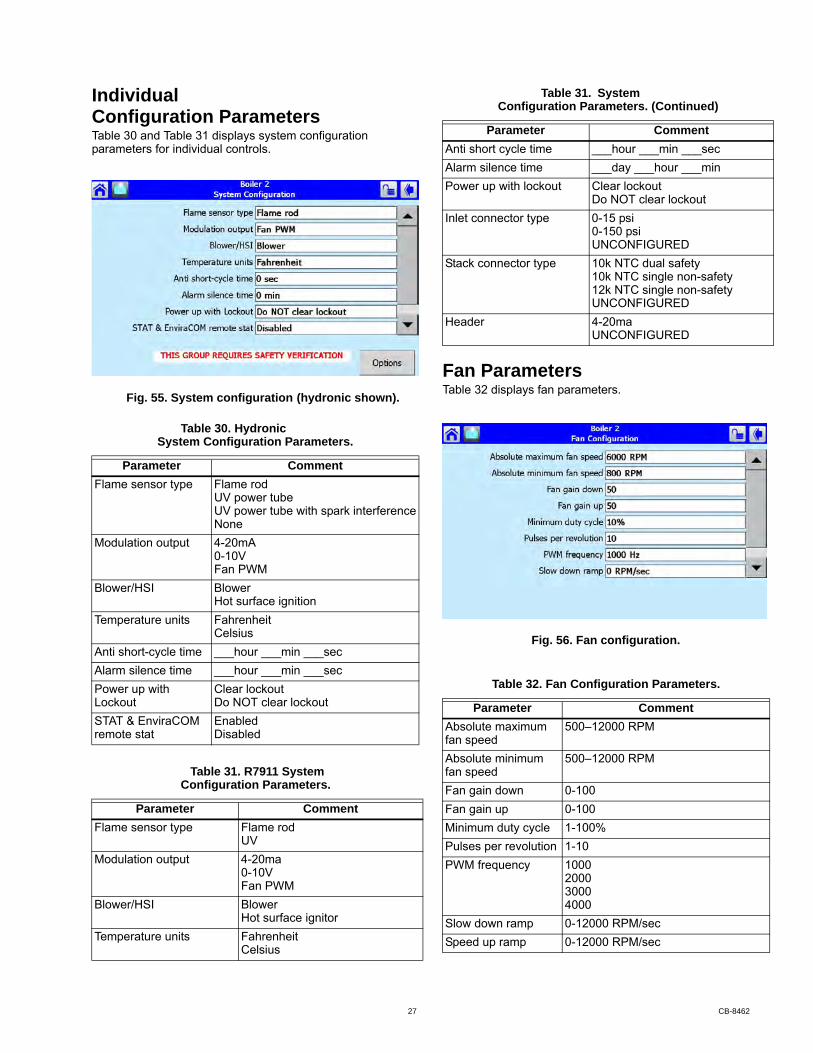
Configuration ParametersTable 30 and Table 31 displays system configuration parameters for individual controls.
Fan ParametersTable 32 displays fan parameters.
Fig. 56. Fan configuration.
System Configuration Parameters.
Parameter CommentFlame sensor type Flame rod
UV power tubeUV power tube with spark interferenceNone
Modulation output 4-20mA0-10VFan PWM
Blower/HSI BlowerHot surface ignition
Temperature units FahrenheitCelsius
Anti short-cycle time ___hour ___min ___secAlarm silence time ___hour ___min ___secPower up with Lockout
Clear lockoutDo NOT clear lockout
STAT & EnviraCOM remote stat
EnabledDisabled
Table 31. R7911 System Configuration Parameters.
Parameter CommentFlame sensor type Flame rod
UVModulation output 4-20ma
0-10VFan PWM
Blower/HSI BlowerHot surface ignitor
Temperature units FahrenheitCelsius
Anti short cycle time ___hour ___min ___secAlarm silence time ___day ___hour ___minPower up with lockout Clear lockout
Do NOT clear lockoutInlet connector type 0-15 psi
0-150 psiUNCONFIGURED
Stack connector type 10k NTC dual safety10k NTC single non-safety12k NTC single non-safetyUNCONFIGURED
Header 4-20maUNCONFIGURED
Table 32. Fan Configuration Parameters.
Parameter CommentAbsolute maximum fan speed
500–12000 RPM
Absolute minimum fan speed
500–12000 RPM
Fan gain down 0-100Fan gain up 0-100Minimum duty cycle 1-100%Pulses per revolution 1-10PWM frequency 1000
200030004000
Slow down ramp 0-12000 RPM/secSpeed up ramp 0-12000 RPM/sec
Configuration Parameters. (Continued)
Parameter Comment
Individual Table 31. System
Fig. 55. System configuration (hydronic shown).
Table 30. Hydronic
27 CB-8462

Lead Lag Slave Configuration Parameters (Hydronic Control Only)Table 33 displays Lead Lag Slave Configuration parameters.
Fig. 57. Lead Lag slave configuration.
Lead Lag Master Configuration Parameters (Hydronic Control Only)Table 34 displays Lead Lag Master Configuration parameters.
Click the Advanced Settings button to see available advanced parameters as shown in Table 34–43.
Use the left and right arrows to switch between Modulation, CH, DHW, Frost Protection, Warm Weather Shutdown, Algorithms, Rate Allocation, Add stage and Drop stage parameters.
Fig. 58. Lead Lag master configuration and Advanced Settings button.
Table 33. Lead Lag Slave Configuration Parameters.
Parameter CommentSlave enable Slave
ModBUS slaveDisabled
Slave mode Use firstUse lastEqualize run time
Base load rate 0–6000 rpmSlave sequence order
0–8
Demand to firing delay
___hour ___min ___sec
Fan rate during off cycle
0–12000 rpm
ModBus port MB1MB2No port
ModBus address 0–250
Table 34. Lead Lag Master Configuration Parameters.
Parameter CommentMaster enable Enabled
DisabledCH setpoint -40 °F to 266 °F (-40 °C to 130 °C)CH time of day setpoint
-40 °F to 266 °F (-40 °C to 130 °C)
ModBus port MB1MB2No port
ModBus address 1–250
Table 35. Lead Lag Master ConfigurationAdvanced Settings: Modulation Parameters.
Parameter CommentModulation backup sensor
Lead outlet sensorSlave outlet sensor averageDisabled
Off hysteresis 0 °F to 234 °F(-17 °C to 112 °C)
On hysteresis 0 °F to 234 °F(-17 °C to 112 °C)
Hysteresis step time ___Hour ____Minute _____SecondP gain 0 - 400I gain 0 - 400D gain 0 - 400
CB-8462 28

Table 36. Lead Lag Master ConfigurationAdvanced Settings: Central Heat Parameters.
Parameter CommentDemand switch Stat
Remote StatModBus StatDisabled
Setpoint source LocalModBus4-20 ma
Setpoint -40 °F to 266 °F (-40 °C to 130 °C)Time of day setpoint -40 °F to 266 °F (-40 °C to 130 °C)4 ma water temperature
-40 °F to 266 °F (-40 °C to 130 °C)
20 ma water temperature
-40 °F to 266 °F (-40 °C to 130 °C)
Outdoor reset EnabledDisabled
Table 37. Lead Lag Master ConfigurationAdvanced Settings: DHW Parameters.
Parameter CommentPriority source DHW heat demand
DisabledPriority method Boost during priority time
Drop after priority timeDHW priority override time
___Hour ____Minute _____Second
Table 38. Lead Lag Master ConfigurationAdvanced Settings: Frost Protection Parameters.
Parameter CommentEnable Enabled
DisabledOutdoor setpoint -40 °F to 266 °F (-40 °C to 130 °C)Frost protection rate ____%
Table 39. Lead Lag Master Configuration AdvancedSettings: Warm Weather Shutdown Parameters.
Parameter CommentEnable Enabled
DisabledSetpoint -40 °F to 266 °F (-40 °C to 130 °C)
Table 40. Lead Lag Master ConfigurationAdvanced Settings: Algorithms Parameters.
Parameter CommentLead selection method
Sequence orderMeasured run time
Lag selection method Sequence orderMeasured run time
Lead rotation time ___day ____hour _____minForce lead rotation time
___day ____hour _____min
Table 41. Lead Lag Master ConfigurationAdvanced Settings: Rate Allocation Parameters.
Parameter CommentBase load common ? %
Table 42. Lead Lag Master ConfigurationAdvanced Settings: Add Stage Parameters.
Parameter CommentMethod Error threshold
Firing rate thresholdDisabled
Detection time ___Hour ____Minute _____SecondError threshold 0 °F to 234 °F (-17 °C to 112 °C)Rate offset + ________ %Interstage delay ___Hour ____Minute _____Second
Table 43. Lead Lag Master ConfigurationAdvanced Settings: Drop Stage Parameters.
Parameter CommentMethod Error threshold
Firing rate threshold
Detection time ___Hour ____Minute _____SecondError threshold 0 °F to 234 °F (-17 °C to 112 °C)Rate offset + ________ %Interstage delay ___Hour ____Minute _____Second
29 CB-8462

DETAILSDetails of the hydronic or steam system is accomplished through the detail status pages. The detail status page is shown below.
Screens will appear only if they are configured for your system.
Information shown is current status. For example: firing rate is the current fan speed or motor position; timing shown is current time Sola is at.
Fig. 59. Hydronic CH detail status page.
Status information on the detail status page is organized into groups and displayed on the page one group at a time. The user moves from one group to another using the left and right arrow buttons.
Status data on the detail status page is displayed in a menu for the group that is currently displayed. If more status items exist in the group than will fit on the screen, a vertical scroll bar allows the user to see all status data. If the user selects a line of status data in the menu, it will expand in bigger, more easily readable text, as show in Fig. 60. Additional information about Status data and groups that are displayed are provided in the R7910A or R7911 Status section of this document.
Fig. 60. Hydronic “expanded” detail status.
Status tables can be found in Table 59 on page 41.
The CH status data shown in Table 44 displays first when the CH Hydronic heating loop is selected on the Home page.
Fig. 61. CH Hydronic Status menu (top).
Table 44. CH Hydronic Status.
Data Comment CH enable Enabled, DisabledCH burner demand On or OffCH pump On or OffCH pump demand On or OffCH pump overrun time
Running overtime for CH pump (seconds)
CH requested rate RPM or %CH OFF setpoint Setpoint plus hysteresisCH setpoint Temp setting between -40 °F to 266 °F
(-40 °C to 130 °C)CH ON setpoint Setpoint minus hysteresis CH setpoint source Normal, TOD, Outdoor reset, Remote
controlCH status Disabled, Normal, SuspendedDemand source Sensor only, Sensor and Stat terminal,
Sensor and Remote Stat, LCI and sensor
Outlet high limit Yes or NoOutlet high limit setpoint
Temp setting between -40 °F to 266 °F (-40 °C to 130 °C)
Outlet sensor state None, Normal, Open, Shorted, Outside high range, Outside low range, Not reliable (None = no outlet sensor)
Outlet temperature Outlet temperature (same as bar graph)
StatusData in Tables 44–Table 55 are displayed on the Hydronic or Steam status pages. A complete list of
CB-8462 30
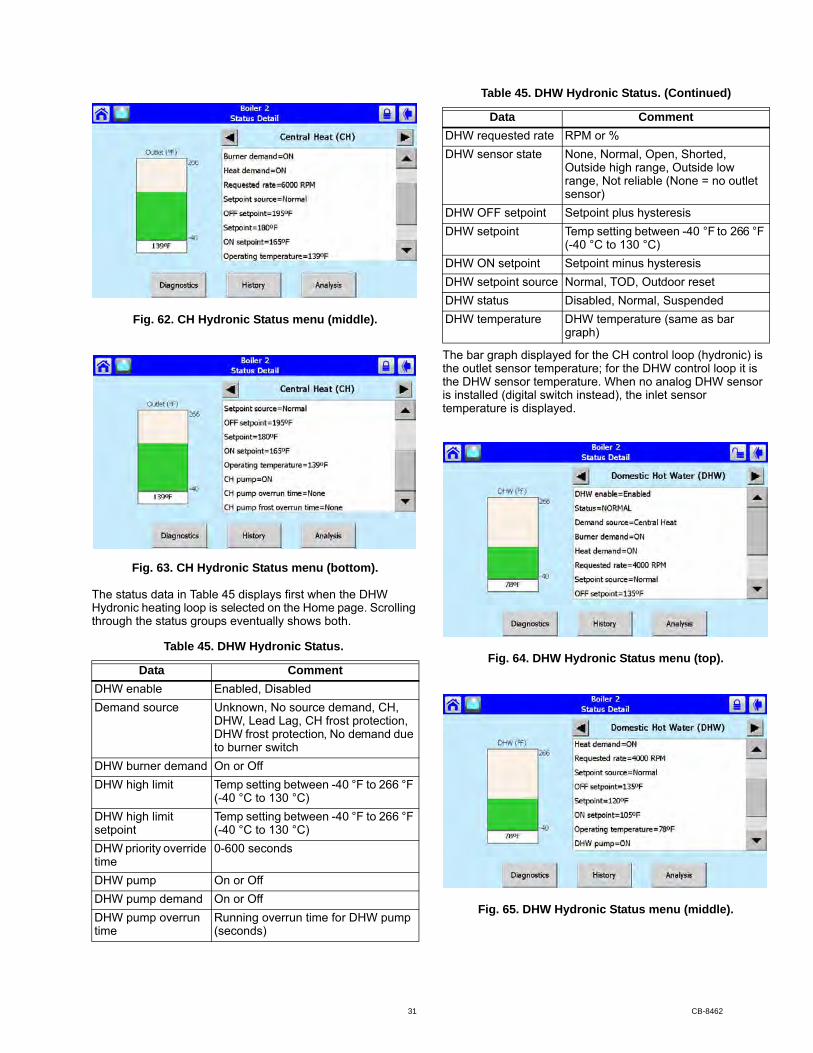
Fig. 62. CH Hydronic Status menu (middle).
Fig. 63. CH Hydronic Status menu (bottom).
The status data in Table 45 displays first when the DHW Hydronic heating loop is selected on the Home page. Scrolling through the status groups eventually shows both.
The bar graph displayed for the CH control loop (hydronic) is the outlet sensor temperature; for the DHW control loop it is the DHW sensor temperature. When no analog DHW sensor is installed (digital switch instead), the inlet sensor temperature is displayed.
Fig. 64. DHW Hydronic Status menu (top).
Fig. 65. DHW Hydronic Status menu (middle).
Table 45. DHW Hydronic Status.
Data Comment DHW enable Enabled, DisabledDemand source Unknown, No source demand, CH,
DHW, Lead Lag, CH frost protection, DHW frost protection, No demand due to burner switch
DHW burner demand On or OffDHW high limit Temp setting between -40 °F to 266 °F
(-40 °C to 130 °C)DHW high limit setpoint
Temp setting between -40 °F to 266 °F (-40 °C to 130 °C)
DHW priority override time
0-600 seconds
DHW pump On or OffDHW pump demand On or OffDHW pump overrun time
Running overrun time for DHW pump (seconds)
DHW requested rate RPM or %DHW sensor state None, Normal, Open, Shorted,
Outside high range, Outside low range, Not reliable (None = no outlet sensor)
DHW OFF setpoint Setpoint plus hysteresisDHW setpoint Temp setting between -40 °F to 266 °F
(-40 °C to 130 °C)DHW ON setpoint Setpoint minus hysteresisDHW setpoint source Normal, TOD, Outdoor resetDHW status Disabled, Normal, SuspendedDHW temperature DHW temperature (same as bar
graph)
Table 45. DHW Hydronic Status. (Continued)
Data Comment
31 CB-8462
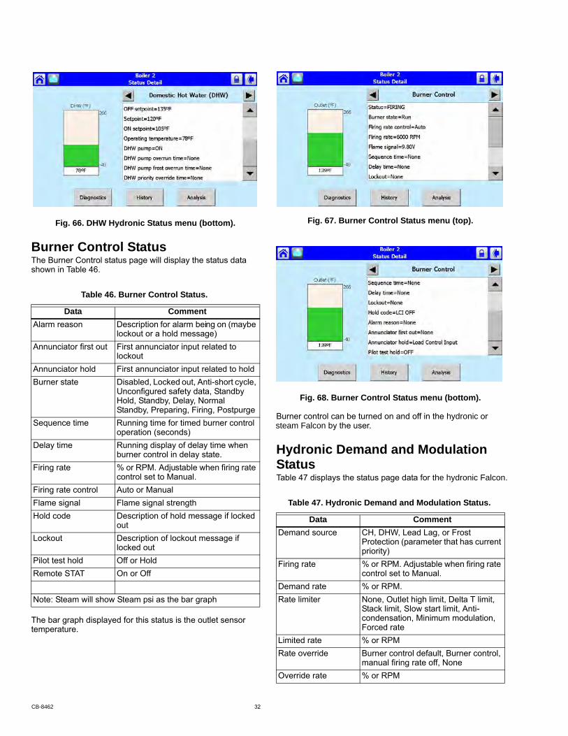
Fig. 66. DHW Hydronic Status menu (bottom).
Burner Control StatusThe Burner Control status page will display the status data shown in Table 46.
The bar graph displayed for this status is the outlet sensor temperature.
Fig. 67. Burner Control Status menu (top).
Fig. 68. Burner Control Status menu (bottom).
Hydronic Demand and Modulation Status
Table 46. Burner Control Status.
Data Comment Alarm reason Description for alarm being on (maybe
lockout or a hold message) Annunciator first out First annunciator input related to
lockout Annunciator hold First annunciator input related to holdBurner state Disabled, Locked out, Anti-short cycle,
Unconfigured safety data, Standby Hold, Standby, Delay, Normal Standby, Preparing, Firing, Postpurge
Sequence time Running time for timed burner control operation (seconds)
Delay time Running display of delay time when burner control in delay state.
Firing rate % or RPM. Adjustable when firing rate control set to Manual.
Firing rate control Auto or Manual Flame signal Flame signal strength Hold code Description of hold message if locked
outLockout Description of lockout message if
locked outPilot test hold Off or HoldRemote STAT On or Off
Note: Steam will show Steam psi as the bar graph
Table 47. Hydronic Demand and Modulation Status.
Data Comment Demand source CH, DHW, Lead Lag, or Frost
Protection (parameter that has current priority)
Firing rate % or RPM. Adjustable when firing rate control set to Manual.
Demand rate % or RPM.Rate limiter None, Outlet high limit, Delta T limit,
Stack limit, Slow start limit, Anti-condensation, Minimum modulation, Forced rate
Limited rate % or RPMRate override Burner control default, Burner control,
manual firing rate off, NoneOverride rate % or RPM
Table 47 displays the status page data for the hydronic Falcon.
Burner control can be turned on and off in the hydronic or steam Falcon by the user.
CB-8462 32
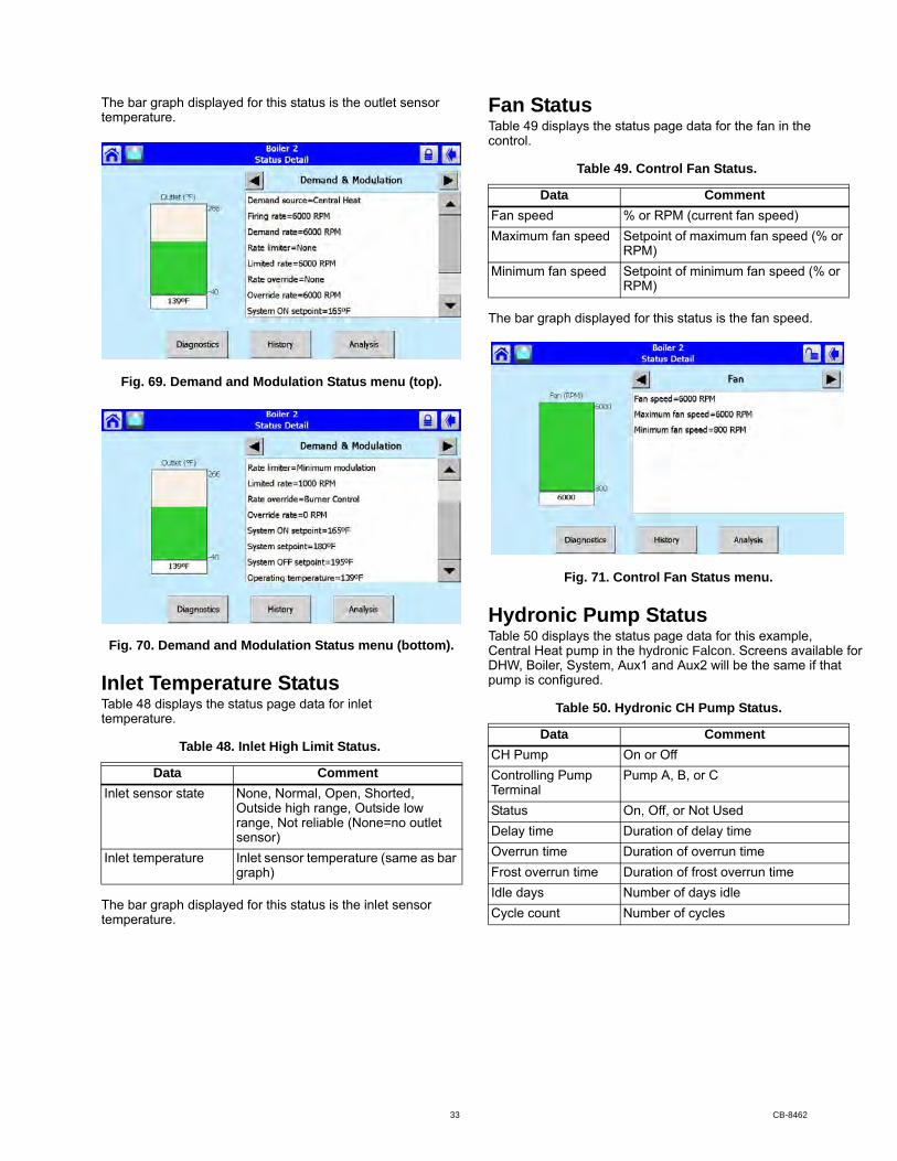
The bar graph displayed for this status is the outlet sensor temperature.
Fig. 69. Demand and Modulation Status menu (top).
Fig. 70. Demand and Modulation Status menu (bottom).
Inlet Temperature Statustemperature.
The bar graph displayed for this status is the inlet sensor temperature.
Fan StatusTable 49 displays the status page data for the fan in the control.
The bar graph displayed for this status is the fan speed.
Fig. 71. Control Fan Status menu.
Hydronic Pump StatusTable 50 displays the status page data for this example,
DHW, Boiler, System, Aux1 and Aux2 will be the same if that pump is configured.
Table 48. Inlet High Limit Status.
Data Comment Inlet sensor state None, Normal, Open, Shorted,
Outside high range, Outside low range, Not reliable (None=no outlet sensor)
Inlet temperature Inlet sensor temperature (same as bar graph)
Table 49. Control Fan Status.
Data Comment Fan speed % or RPM (current fan speed) Maximum fan speed Setpoint of maximum fan speed (% or
RPM) Minimum fan speed Setpoint of minimum fan speed (% or
RPM)
Table 50. Hydronic CH Pump Status.
Data CommentCH Pump On or OffControlling Pump Terminal
Pump A, B, or C
Status On, Off, or Not UsedDelay time Duration of delay timeOverrun time Duration of overrun timeFrost overrun time Duration of frost overrun timeIdle days Number of days idleCycle count Number of cycles
Central Heat pump in the hydronic Falcon. Screens available for
Table 48 displays the status page data for inlet
33 CB-8462

Fig. 72. Hydronic CH pump status menu.
Flame Detection StatusThe status data shown in Table 51 is displayed for flame
The bar graph displayed for this status is the flame signal.
Fig. 73. Flame Detection Status menu.
NOTE: This same status is also displayed for burner control status. A separate status group is defined to provide a bar graph of the flame signal.
Statistics Status
pump, the output can be used to run some other auxiliary equipment.
The bar graph displayed for this status is the outlet sensor temperature.
Fig. 74. Control Statistics Status menu (top).
Stack Limit StatusTable 53 shows the status page data for the control Stack Limit.
The bar graph displayed for this status is the stack sensor temperature.
Lead Lag Slave Status - Hydronic OnlyTable 54 shows the status page data for Lead Lag Slave.
Table 51. Flame Detection Status.
Data Comment Flame detected Yes or No Flame signal Flame signal strength (same as bar
graph)Pilot test hold Off or hold
Table 52. Control Statistics Status.
Data Comment Burner cycles Number of cyclesBurner run time Duration of run timeCH pump cycles Number of cyclesSystem pump cycles Number of cyclesController cycles Number of cyclesController run time Duration of run time
Table 53. Stack Limit Status.
Data Comment Stack limit enable Enabled or DisabledStack limit Temp setting between -40 °F to 266 °F
(-40 °C to 130 °C)Stack limit setpoint Temp setting between -40 °F to 266 °F
(-40 °C to 130 °C)Stack sensor state None, Normal, Open, Shorted,
Outside high range, Outside low range, Not reliable (None=no stack temp sensor)
Stack temperature Stack sensor temperature (same as bar graph)
detection.
Though the Steam control will not have a Table 52 displays the statistics status page data.
CB-8462 34
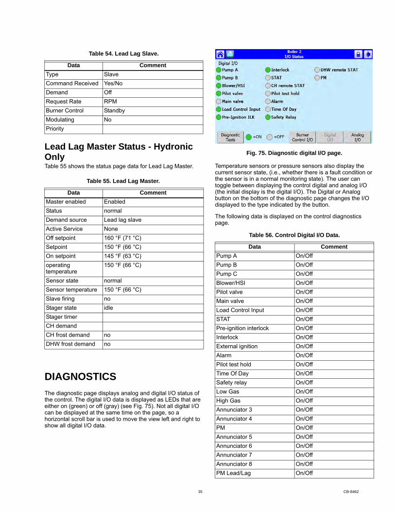
Lead Lag Master Status - Hydronic OnlyTable 55 shows the status page data for Lead Lag Master.
DIAGNOSTICSThe diagnostic page displays analog and digital I/O status of the control. The digital I/O data is displayed as LEDs that are either on (green) or off (gray) (see Fig. 75). Not all digital I/O can be displayed at the same time on the page, so a horizontal scroll bar is used to move the view left and right to show all digital I/O data.
Fig. 75. Diagnostic digital I/O page.
Temperature sensors or pressure sensors also display the current sensor state, (i.e., whether there is a fault condition or the sensor is in a normal monitoring state). The user can toggle between displaying the control digital and analog I/O (the initial display is the digital I/O). The Digital or Analog button on the bottom of the diagnostic page changes the I/O displayed to the type indicated by the button.
The following data is displayed on the control diagnostics page.
Table 54. Lead Lag Slave.
Data CommentType SlaveCommand Received Yes/NoDemand OffRequest Rate RPMBurner Control StandbyModulating NoPriority
Table 55. Lead Lag Master.
Data CommentMaster enabled EnabledStatus normalDemand source Lead lag slaveActive Service NoneOff setpoint 160 °F (71 °C)Setpoint 150 °F (66 °C)On setpoint 145 °F (63 °C)operating temperature
150 °F (66 °C)
Sensor state normalSensor temperature 150 °F (66 °C)Slave firing noStager state idleStager timerCH demandCH frost demand noDHW frost demand no
Table 56. Control Digital I/O Data.
Data CommentPump A On/OffPump B On/OffPump C On/OffBlower/HSI On/OffPilot valve On/OffMain valve On/OffLoad Control Input On/OffSTAT On/OffPre-ignition interlock On/OffInterlock On/OffExternal ignition On/OffAlarm On/OffPilot test hold On/OffTime Of Day On/OffSafety relay On/OffLow Gas On/OffHigh Gas On/OffAnnunciator 3 On/OffAnnunciator 4 On/OffPM On/OffAnnunciator 5 On/OffAnnunciator 6 On/OffAnnunciator 7 On/OffAnnunciator 8 On/OffPM Lead/Lag On/Off
35 CB-8462
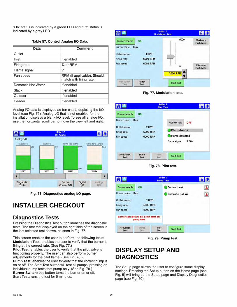
“On” status is indicated by a green LED and “Off” status is indicated by a gray LED.
Analog I/O data is displayed as bar charts depicting the I/O level (see Fig. 76). Analog I/O that is not enabled for the installation displays a blank I/O level. To see all analog I/O, use the horizontal scroll bar to move the view left and right.
Fig. 76. Diagnostics analog I/O page.
INSTALLER CHECKOUT
Diagnostics TestsPressing the Diagnostics Test button launches the diagnostic tests. The first test displayed on the right side of the screen is the last selected test shown, as seen in Fig. 77.
This screen enables the user to perform the following tests:Modulation Test: enables the user to verify that the burner is firing at the correct rate. (See Fig. 77.)Pilot Test: enables the user to verify that the pilot valve is functioning properly. The user can also perform burner adjustments for the pilot flame. (See Fig. 78.)Pump Test: enables the user to verify that the correct pump is on or off. The Start Test button will test all pumps; pressing an individual pump tests that pump only. (See Fig. 79.)Burner Switch: this button turns the burner on or off.Start Test: runs the test for 5 minutes.
Fig. 77. Modulation test.
Fig. 78. Pilot test.
Fig. 79. Pump test.
DIAGNOSTICSThe Setup page allows the user to configure some display settings. Pressing the Setup button on the Home page (see Fig. 5) will bring up the Setup page and Display Diagnostics page (see Fig. 80).
Table 57. Control Analog I/O Data.
Data CommentOutletInlet If enabledFiring rate % or RPMFlame signal VFan speed RPM (if applicable). Should
match with firing rate.Domestic Hot Water If enabledStack If enabledOutdoor If enabledHeader If enabled
DISPLAY SETUP AND
CB-8462 36

Fig. 80. Setup page.
Press the Display Setup page to display various options that can be set by the user (see Fig. 81 to Fig. 85)
The General tab (Fig. 81) contains the following settings:
• Display alerts on Status Summary Bar? This determines whether non-safety alerts will be shown on the summary bar of the home page
• Display empty parameter groups? This cleans up the home page by hiding unused parameter groups
• Sound audio alarm for faults? This uses the display
Fig. 81. Setup page - General setup.
The COM1 tab (see Fig. 82) contains the following setting:• Enable COM1 port: This box must be selected to enables
the COM1 interface• Modbus address range 1-N: Sets the Modbus address for
the connected device (range is 1 to 250).• Modbus baud rate: Select the baud rate (38400, 19200 or
9600 bps)The COM2 is Modbus gateway for Building Automation System (BAS) networking:• Enable COM2 port: This box must be selected to enables
the COM2 BAS interface
• Modbus address range 1-N: Sets the Modbus address for the connected device (range is 1 to 250).
• Modbus baud rate: Select the baud rate (38400, 19200 or 9600 bps)
Fig. 82. Setup page - Com ports setup.
Fig. 83. Setup page - Gateway setup.
Fig. 84. Setup page - Screen setup.
speaker to sound an alarm on shutdown for Falcon faults
37 CB-8462

Fig. 85. Setup page - Language setup.
Trend Analysis Page
Pressing the device icon, then the “Details” button, will bring up the “Status Details” screen (see Fig. 59). Press the “Analysis” button to access trend variables (see Fig. 87 and Fig. 88).
A 2-dimensional graph with status data values shown on the Y axis over time specified on the X axis is displayed. Status for the most recent time is represented on the left side of the graph with older status running towards the right side of the graph.
Fig. 86. Trend analysis page.
same time on one trend analysis graph. Select the status variables for the graph on the menu page (see Fig. 87). This menu displays when the Trend Analysis button is selected on
Fig. 87. Trend analysis menu page.
The status variable with the largest range (minimum to maximum) is used as the Y-axis range in the graph.
As the status variables are selected they are listed in a trend variables list box. The user chooses the status variables from a drop down menu and then presses the Add button to add each status variable to the trend variable list.
Each status variable displayed in the trend analysis is represented by a different colored line, as follows:
1. First status variable = green2. Second status variable = yellow3. Third status variable = red4. Fourth status variable = blue
No more than two different measurement units (such as degrees), are allowed for the status variables selected in the trend analysis graph. Attempts to add a status variable with a third measurement unit are rejected.
A second Y axis is displayed on the right side of the graph to represent the scale for the second measurement unit. This can result in minor clipping of the curves on the right side, as shown in Fig. 88 and 89.
Fig. 88. Trend analysis page with firing rate.
Trend analysis of FAlcon status data can be viewed
status data over varying time periods.on the display. A graph displays a historical view of
Up to 4 status variables can be viewed at the
the status page.
CB-8462 38
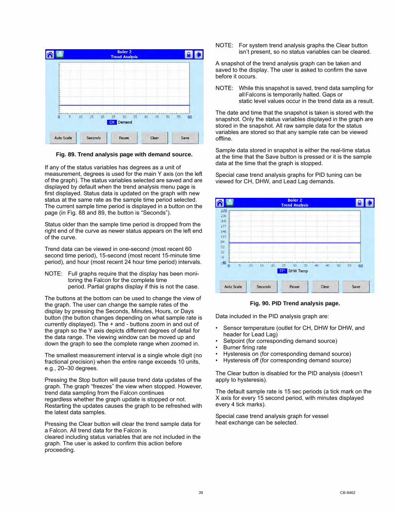
Fig. 89. Trend analysis page with demand source.
If any of the status variables has degrees as a unit of measurement, degrees is used for the main Y axis (on the left of the graph). The status variables selected are saved and are displayed by default when the trend analysis menu page is first displayed. Status data is updated on the graph with new status at the same rate as the sample time period selected. The current sample time period is displayed in a button on the page (in Fig. 88 and 89, the button is “Seconds”).
Status older than the sample time period is dropped from the right end of the curve as newer status appears on the left end of the curve.
Trend data can be viewed in one-second (most recent 60 second time period), 15-second (most recent 15-minute time period), and hour (most recent 24 hour time period) intervals.
period. Partial graphs display if this is not the case.
The buttons at the bottom can be used to change the view of the graph. The user can change the sample rates of the display by pressing the Seconds, Minutes, Hours, or Days button (the button changes depending on what sample rate is currently displayed). The + and - buttons zoom in and out of the graph so the Y axis depicts different degrees of detail for the data range. The viewing window can be moved up and down the graph to see the complete range when zoomed in.
The smallest measurement interval is a single whole digit (no fractional precision) when the entire range exceeds 10 units, e.g., 20–30 degrees.
Pressing the Stop button will pause trend data updates of the graph. The graph “freezes” the view when stopped. However,
regardless whether the graph update is stopped or not. Restarting the updates causes the graph to be refreshed with the latest data samples.
Pressing the Clear button will clear the trend sample data for
cleared including status variables that are not included in the graph. The user is asked to confirm this action before proceeding.
NOTE: For system trend analysis graphs the Clear button isn’t present, so no status variables can be cleared.
A snapshot of the trend analysis graph can be taken and
before it occurs.
NOTE: While this snapshot is saved, trend data sampling for
static level values occur in the trend data as a result.
The date and time that the snapshot is taken is stored with the snapshot. Only the status variables displayed in the graph are stored in the snapshot. All raw sample data for the status variables are stored so that any sample rate can be viewed offline.
Sample data stored in snapshot is either the real-time status at the time that the Save button is pressed or it is the sample data at the time that the graph is stopped.
Special case trend analysis graphs for PID tuning can be viewed for CH, DHW, and Lead Lag demands.
Fig. 90. PID Trend analysis page.
Data included in the PID analysis graph are:
• Sensor temperature (outlet for CH, DHW for DHW, and header for Lead Lag)
• Setpoint (for corresponding demand source)• Burner firing rate• Hysteresis on (for corresponding demand source)• Hysteresis off (for corresponding demand source)
The Clear button is disabled for the PID analysis (doesn’t apply to hysteresis).
The default sample rate is 15 sec periods (a tick mark on the X axis for every 15 second period, with minutes displayed every 4 tick marks).
heat exchange can be selected.
NOTE: Full graphs require that the display has been moni-toring the Falcon for the complete time
trend data sampling from the Falcon continues
a Falcon. All trend data for the Falcon is
saved to the display. The user is asked to confirm the save
all Falcons is temporarily halted. Gaps or
Special case trend analysis graph for vessel
39 CB-8462

Fig. 91. Vessel analysis page.
Data included in the vessel analysis graph are:
• Outlet temperature• Inlet temperature• Heat exchange (outlet – inlet)• Burner firing rate
Automatic sampling of trend data takes place when the trend analysis report is displayed. No user intervention is necessary to invoke sampling.
over with no data.
is possible:
Trend Analysis SnapshotThe trend analysis snapshot file is stored in Comma
imported into a spreadsheet program such as Microsoft Excel.
The trend analysis snapshot file can be viewed in graph form
DiagnosticsPressing the Diagnostics button permits some display hardware diagnostics (see Fig. 92). Normally, these diagnostics are applicable only for factory testing purposes, but conditions may arise that warrant this testing.
Fig. 92. Display diagnostics.
NOTE: COM 1 Communication test is a factory-only test. Performing this text when not connected to a factory test fixture will always yield a “Failed” result.
Each test is invoked by pressing the Test button next to the diagnostic. The results of the diagnostic test (“PASS” or “FAIL”) display in the text box next to the Test button.
Date and Time
at the display and any data that is timestamped is marked with the current time and date in the display.
The Display clock is set by selecting the “Set Date/Time” button on the Display Setup page (see Fig. 84).
Data CommentDemand source CH, DHW, LL (Lead Lag), or
FP (Frost Protection) Steam Sensor
only)Firing rate % or RPMFan speed PWM feedbackFlame signal strength V
only)
only)Outdoor temperature If enabledStack temperature If enabled
only)CH setpoint Actual CH setpoint based on
time of day (TOD).
DHW setpoint (R7910 only) Actual DHW setpoint based on TOD.
Central Heat Operation AnalysisDomestic Hot Water Operation Analysis (R7910 only)Vessel Analysis
Table 58. R7910/R7911 Trend Analysis Data. (Continued)
Data Comment
on the display. It can also be copied to a USB device.
Separated Value (CSV) format in the 833-5105 so it can be
NOTE: Sample data is collected and stored in the 833-5105. The Falcon control does not collect any historical data for trending purposes. For this reason any display reset causes all sampling to start
Trend analysis of the following data from each Falcon control
Table 58. Trend Analysis Data.
Outlet temperature (hydronic
DHW temperature (hydronic If enabled
Header temperature (hydronic If enabled
Inlet temperature (hydronic If enabled
Display time can be configured in the 833-5105 and applied to the Falcon. A date and time is entered by the user
CB-8462 40

NOTE: It’s important that the time be set in the Display
to be set should power be interrupted to the dis-play.
Fig. 93. Display Date and Time.
Edit the date and time and press the OK button to set the new settings. Press the Cancel button to exit without changing the time or date.
VersionPressing the Version button on the Advanced Setup page displays manufacturer and software version information (Fig. 94).
Fig. 94. Code version.
Display ResetThe user can reset the display and force a power-up by pressing the Display Reset button. A pop-up dialog box confirming the reset request displays (Fig. 95) before the reset proceeds.
Fig. 95. Processor Reset.
When the Display is reset, the display will reboot and automatically seek out the Modbus™ device connected to it. When the search is complete, the display will return to the home page.
Table 59. Status Tables.
Name Table # Page #CH 44 30DHW 45 31Burner Control 46 32Demand and Modulation 47 32Inlet High Limit 48 33Fan 49 33Pump 50 33Flame Detection 51 34Statistics 52 34Stack Limit 53 34Lead Lag Slave 54 35Lead Lag Master 55 35
lockouts. The display’s time and date need so correct timestamps are given to Falcon
41 CB-8462

ParametersA complete list of configurable parameters is shown in Table 60.
Table 60. Configurable Parameters.
Parameter CommentTable
#Page
#Boiler Name Name to identify boiler (up to 20
characters)5 14
Installation Notes regarding installation (up to 20 characters)
Installer password
Change installer password setting
OEM password
Change OEM password setting
Factory Data OEM name to associate with boiler (up to 20 characters)
CH enable Disable or Enable Central Heating Loop
7 14
CH demand switch
Sensor for Central Heat demand:Sensor onlySensor & STAT terminalSensor & Remote StatLCI & Sensor
CH Outdoor reset
EnabledDisabled
CH has priority over Lead Lag
Yes, No, Cancel
CH Setpoint source
LocalS2 (J8-6) 4-20mA
CH Setpoint Setpoint for normal Central Heat modulation:-40 °F to 266 °F(-40 °C to 130 °C)
CH time of day setpoint
Setpoint when Time Of Day switch is on. -40 °F to 266 °F(-40 °C to 130 °C)
CH off hysteresis
Differential above setpoint when boiler is turned off. -40 °F to 266 °F (-40 °C to 130 °C)
CH on hysteresis
Differential from setpoint when boiler is turned on.-40 °F to 266 °F (-40 °C to 130 °C)
4 mA water temperature
-40 °F to 266 °F (-40 °C to 130 °C)
20 mA water temperature
-40 °F to 266 °F (-40 °C to 130 °C)
Modulation sensor
Outlet sensor, Inlet sensor, S5 (J8-11)
Modulation Rate Sensor
Local
CH P-gain Time between hysteresis step changes: 0-400
CH I-gain Time between hysteresis step changes: 0-400
CH D-gain Time between hysteresis step changes: 0-400
Hysteresis step time
Time between hysteresis step changes: 0-600 seconds (0=Disable hysteresis stepping)
Table 60. Configurable Parameters. (Continued)
Parameter CommentTable
#Page
#
CB-8462 42

Steam enable
Disable/enable steam feature 8 15
Steam demand source
Sensor and LCISensor and Remote StatSensor and Stat TerminalSensor Only
Steam pressure setpoint
Setpoint for normal modulationAdjustable 0 to 15 or 0 to 150 (sensor dependant)
Steam time of day setpoint
Setpoint when TOD switch on Adjustable 0 to 15 or 0 to 150 (sensor dependant)
Minimum steam pressure
Establishes setpoint for the 4ma. input. Adjustable 0 to 15 or 0 to 150 (sensor dependant)
Steam pressure off hysteresis
Differential below setpoint when boiler is turned offAdjustable 0 to 15 or 0 to 150 (sensor dependant)
Steam pressure on hysteresis
Differential from setpoint when boileris turned on.Adjustable 0 to 15 or 0 to 150 (sensor dependant)
Steam hysteresis step time
Time between hysteresis changes 0 to 600 seconds (0=disable)
Steam P Gain
Gain applied for the P portion of the PID equation0-400
Steam I Gain Gain applied for the I portion of the PID Equation - 0-400
Steam D Gain
Gain applied for the D portion of the PID equation0-400
Steam 4-20 ma remote control
uses 4-20ma remote control function to control either the setpoint or modulation for Steam Disable, setpoint, modulation
CH maximum outdoor temperature
-40 °F to 266 °F (-40 °C to 130 °C)
9 15
CH minimum outdoor temperature
-40 °F to 266 °F (-40 °C to 130 °C)
Low water temperature
-40 °F to 266 °F (-40 °C to 130 °C)
Minimum water temperature
-40 °F to 266 °F (-40 °C to 130 °C)
Maximum off point
-40 °F to 266 °F (-40 °C to 130 °C)
Table 60. Configurable Parameters. (Continued)
Parameter CommentTable
#Page
#DHW enable Disable or Enable Domestic Hot
Water Loop10 16
DHW demand switch
Sensor for Central Heat demand:DHW sensor only,DHW sensor & Remote Stat,DHW switch & inlet sensor, orDHW switch & outlet sensor
DHW Priority source
Which system has priority:Disabled orHeat Demand
DHW Priority method
Boost during priority timeDrop after priority time
DHW Modulation sensor
DHW SensorOutlet SensorInlet SensorAuto: DHW (S6) or Inlet SensorAuto: DHW (S6) or Outlet Sensor
DHW setpoint
-40 °F to 240 °F (-40 °C to 115 °C)
DHW time of day setpoint
Setpoint when Time Of Day switch is on. -40 °F to 240 °F (-40 °C to 115 °C)
DHW off hysteresis
Differential above setpoint when boiler is turned off. -40 °F to 240 °F (-40 °C to 115 °C)
DHW on hysteresis
Differential from setpoint when boiler is turned on. 2 °F to 234 °F (-16 °C to 112 °C)
DHW priority override time
___hour ___min ___sec
DHW hysteresis step time
Time between hysteresis step changes: 0-600 seconds (0=Disable hysteresis stepping)
DHW priority vs CH
Which system has priority:Central Heat over Domestic Hot Water, or Domestic Hot Water over Central Heat
DHW priority vs LL
Which system has priority:Lead Lag over Domestic Hot Water,Domestic Hot Water over Lead Lag
DHW P-gain Time between hysteresis step changes: 0-400
DHW I-gain Time between hysteresis step changes: 0-400
DHW D-gain Time between hysteresis step changes: 0-400
Table 60. Configurable Parameters. (Continued)
Parameter CommentTable
#Page
#
43 CB-8462
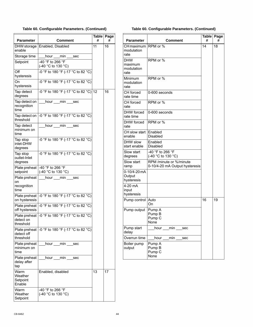
DHW storage enable
Enabled, Disabled 11 16
Storage time ___hour ___min ___secSetpoint -40 °F to 266 °F
(-40 °C to 130 °C)Off hysteresis
-0 °F to 180 °F (-17 °C to 82 °C)
On hysteresis
-0 °F to 180 °F (-17 °C to 82 °C)
Tap detect degrees
-0 °F to 180 °F (-17 °C to 82 °C) 12 16
Tap detect on recognition time
___hour ___min ___sec
Tap detect on threshold
-0 °F to 180 °F (-17 °C to 82 °C)
Tap detect minimum on time
___hour ___min ___sec
Tap stop inlet-DHW degrees
-0 °F to 180 °F (-17 °C to 82 °C)
Tap stop outlet-Inlet degrees
-0 °F to 180 °F (-17 °C to 82 °C)
Plate preheat setpoint
-40 °F to 266 °F (-40 °C to 130 °C)
Plate preheat on recognition time
___hour ___min ___sec
Plate preheat on hysteresis
-0 °F to 180 °F (-17 °C to 82 °C)
Plate preheat off hysteresis
-0 °F to 180 °F (-17 °C to 82 °C)
Plate preheat detect on threshold
-0 °F to 180 °F (-17 °C to 82 °C)
Plate preheat detect off threshold
-0 °F to 180 °F (-17 °C to 82 °C)
Plate preheat minimum on time
___hour ___min ___sec
Plate preheat delay after tap
___hour ___min ___sec
Warm Weather Setpoint Enable
Enabled, disabled 13 17
Warm Weather Setpoint
-40 °F to 266 °F (-40 °C to 130 °C)
Table 60. Configurable Parameters. (Continued)
Parameter CommentTable
#Page
#CH maximum modulation rate
RPM or % 14 18
DHW maximum modulation rate
RPM or %
Minimum modulation rate
RPM or %
CH forced rate time
0-600 seconds
CH forced rate
RPM or %
DHW forced rate time
0-600 seconds
DHW forced rate
RPM or %
CH slow start enable
EnabledDisabled
DHW slow start enable
EnabledDisabled
Slow start degrees
-40 °F to 266 °F (-40 °C to 130 °C)
Slow start ramp
RPM /minute or %/minute0-10/4-20 mA Output hysteresis
0-10/4-20 mA Output hysteresis4-20 mA input hysteresisPump control Auto
On16 19
Pump output Pump APump BPump CNone
Pump start delay
___hour ___min ___sec
Overrun time ___hour ___min ___secBoiler pump output
Pump APump BPump CNone
Table 60. Configurable Parameters. (Continued)
Parameter CommentTable
#Page
#
CB-8462 44
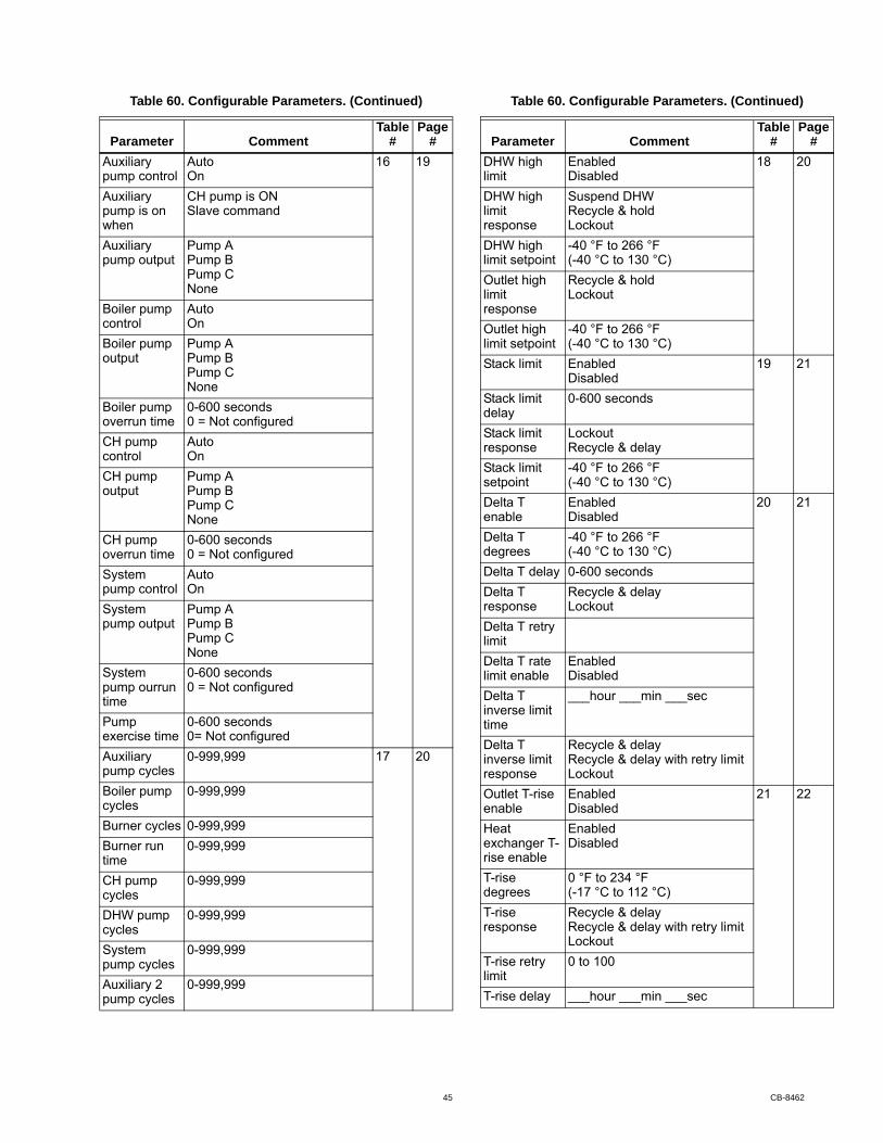
Auxiliary pump control
AutoOn
16 19
Auxiliary pump is on when
CH pump is ONSlave command
Auxiliary pump output
Pump APump BPump CNone
Boiler pump control
AutoOn
Boiler pump output
Pump APump BPump CNone
Boiler pump overrun time
0-600 seconds0 = Not configured
CH pump control
Auto On
CH pump output
Pump APump BPump CNone
CH pump overrun time
0-600 seconds0 = Not configured
System pump control
AutoOn
System pump output
Pump APump BPump CNone
System pump ourrun time
0-600 seconds0 = Not configured
Pump exercise time
0-600 seconds0= Not configured
Auxiliary pump cycles
0-999,999 17 20
Boiler pump cycles
0-999,999
Burner cycles 0-999,999Burner run time
0-999,999
CH pump cycles
0-999,999
DHW pump cycles
0-999,999
System pump cycles
0-999,999
Auxiliary 2 pump cycles
0-999,999
Table 60. Configurable Parameters. (Continued)
Parameter CommentTable
#Page
#DHW high limit
EnabledDisabled
18 20
DHW high limit response
Suspend DHWRecycle & holdLockout
DHW high limit setpoint
-40 °F to 266 °F (-40 °C to 130 °C)
Outlet high limit response
Recycle & holdLockout
Outlet high limit setpoint
-40 °F to 266 °F (-40 °C to 130 °C)
Stack limit EnabledDisabled
19 21
Stack limit delay
0-600 seconds
Stack limit response
LockoutRecycle & delay
Stack limit setpoint
-40 °F to 266 °F (-40 °C to 130 °C)
Delta T enable
EnabledDisabled
20 21
Delta T degrees
-40 °F to 266 °F (-40 °C to 130 °C)
Delta T delay 0-600 secondsDelta T response
Recycle & delayLockout
Delta T retry limitDelta T rate limit enable
EnabledDisabled
Delta T inverse limit time
___hour ___min ___sec
Delta T inverse limit response
Recycle & delayRecycle & delay with retry limitLockout
Outlet T-rise enable
EnabledDisabled
21 22
Heat exchanger T-rise enable
EnabledDisabled
T-rise degrees
0 °F to 234 °F (-17 °C to 112 °C)
T-rise response
Recycle & delayRecycle & delay with retry limitLockout
T-rise retry limit
0 to 100
T-rise delay ___hour ___min ___sec
Table 60. Configurable Parameters. (Continued)
Parameter CommentTable
#Page
#
45 CB-8462
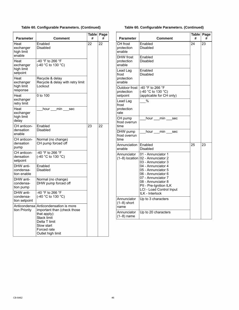
Heat exchanger high limit enable
EnabledDisabled
22 22
Heat exchanger high limit setpoint
-40 °F to 266 °F (-40 °C to 130 °C)
Heat exchanger high limit response
Recycle & delayRecycle & delay with retry limitLockout
Heat exchanger retry limit
0 to 100
Heat exchanger high limit delay
___hour ___min ___sec
CH anticon-densation enable
EnabledDisabled
23 22
CH anticon-densation pump
Normal (no change)CH pump forced off
CH anticon-densation setpoint
-40 °F to 266 °F (-40 °C to 130 °C)
DHW anti-condensa-tion enable
EnabledDisabled
DHW anti-condensa-tion pump
Normal (no change)DHW pump forced off
DHW anti-condensa-tion setpoint
-40 °F to 266 °F (-40 °C to 130 °C)
Anticondensation Priority
Anticondensation is more important than (check those that apply):Stack limitDelta T limitSlow startForced rateOutlet high limit
Table 60. Configurable Parameters. (Continued)
Parameter CommentTable
#Page
#CH frost protection enable
EnabledDisabled
24 23
DHW frost protection enable
EnabledDisabled
Lead Lag frost protection enable
EnabledDisabled
Outdoor frost protection setpoint
-40 °F to 266 °F (-40 °C to 130 °C) (applicable for CH only)
Lead Lag frost protection rate
___%
CH pump frost overrun time
___hour ___min ___sec
DHW pump frost overrun time
___hour ___min ___sec
Annunciation enable
EnabledDisabled
25 23
Annunciator (1–8) location
01 - Annunciator 102 - Annunciator 203 - Annunciator 304 - Annunciator 405 - Annunciator 506 - Annunciator 607 - Annunciator 708 - Annunciator 8PII - Pre-Ignition ILKLCI - Load Control InputILK - Interlock
Annunciator (1–8) short name
Up to 3 characters
Annunciator (1–8) name
Up to 20 characters
Table 60. Configurable Parameters. (Continued)
Parameter CommentTable
#Page
#
CB-8462 46
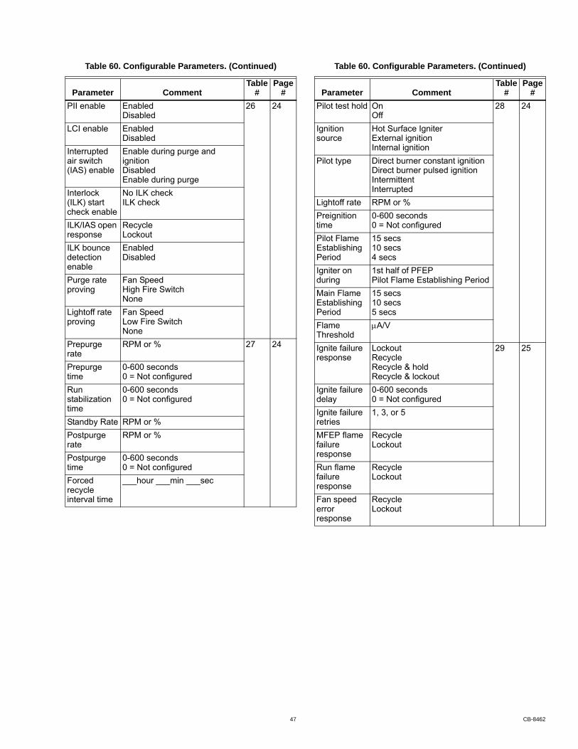
PII enable EnabledDisabled
26 24
LCI enable EnabledDisabled
Interrupted air switch (IAS) enable
Enable during purge and ignitionDisabledEnable during purge
Interlock (ILK) start check enable
No ILK checkILK check
ILK/IAS open response
RecycleLockout
ILK bounce detection enable
EnabledDisabled
Purge rate proving
Fan SpeedHigh Fire SwitchNone
Lightoff rate proving
Fan SpeedLow Fire SwitchNone
Prepurge rate
RPM or % 27 24
Prepurge time
0-600 seconds0 = Not configured
Run stabilization time
0-600 seconds0 = Not configured
Standby Rate RPM or %Postpurge rate
RPM or %
Postpurge time
0-600 seconds0 = Not configured
Forced recycle interval time
___hour ___min ___sec
Table 60. Configurable Parameters. (Continued)
Parameter CommentTable
#Page
#Pilot test hold On
Off28 24
Ignition source
Hot Surface IgniterExternal ignitionInternal ignition
Pilot type Direct burner constant ignitionDirect burner pulsed ignitionIntermittentInterrupted
Lightoff rate RPM or %Preignition time
0-600 seconds0 = Not configured
Pilot Flame Establishing Period
15 secs10 secs4 secs
Igniter on during
1st half of PFEPPilot Flame Establishing Period
Main Flame Establishing Period
15 secs10 secs5 secs
Flame Threshold
A/V
Ignite failure response
LockoutRecycleRecycle & holdRecycle & lockout
29 25
Ignite failure delay
0-600 seconds0 = Not configured
Ignite failure retries
1, 3, or 5
MFEP flame failure response
RecycleLockout
Run flame failure response
RecycleLockout
Fan speed error response
RecycleLockout
Table 60. Configurable Parameters. (Continued)
Parameter CommentTable
#Page
#
47 CB-8462

Flame sensor type
Flame rodUV power tubeUV power tube with spark interferenceNone
30 27
Modulation output
4-20mA0-10VFan PWM*
Blower/HSI BlowerHot surface ignition
Temperature units
FahrenheitCelsius
Anti short-cycle time
0-600 seconds0 = Not configured
Alarm silence time
0-600 minutes0 = Not configured
Power up with Lockout
Clear lockoutDo NOT clear lockout
STAT & EnviraCOM remote stat
EnabledDisabled
Flame sensor type
Flame rodUV
31 27
Modulation output
4-20ma0-10VFan PWM
Blower/HSI BlowerHot surface ignitor
Temperature units
FahrenheitCelsius
Anti short cycle time
0-600 minutes
Alarm silence time
0-600 minutes
Power up with lockout
Clear lockoutDo NOT clear lockout
Inlet connector type
0-15 psi0-150 psiUNCONFIGURED
Stack connector type
10k NTC dual safety10k NTC single non-safety12k NTC single non-safetyUNCONFIGURED
Header 4-20maUNCONFIGURED
Table 60. Configurable Parameters. (Continued)
Parameter CommentTable
#Page
#Absolute maximum fan speed
RPM 32 27
Absolute minimum fan speed
RPM
Fan gain down
0-100
Fan gain up 0-100Minimum duty cycle
1-100%
Pulses per revolution
1-10
PWM frequency
1000200030004000
Slow down ramp
0-12000 RPM/sec
Speed up ramp
0-12000 RPM/sec
Slave enable SlaveModBUS slaveDisabled
33 28
Slave mode Use firstUse lastEqualize run time
Base load rate
0–6000 rpm
Slave sequence order
0–8
Demand to firing delay
___hour ___min ___sec
Fan rate during off cycle
0–12000 rpm
ModBus port MB1MB2No port
ModBus address
0–250
Master enable
EnabledDisabled
34 28
CH setpoint -40 °F to 266 °F (-40 °C to 130 °C)
CH time of day setpoint
-40 °F to 266 °F (-40 °C to 130 °C)
ModBus port MB1MB2No port
ModBus address
0–250
Table 60. Configurable Parameters. (Continued)
Parameter CommentTable
#Page
#
CB-8462 48
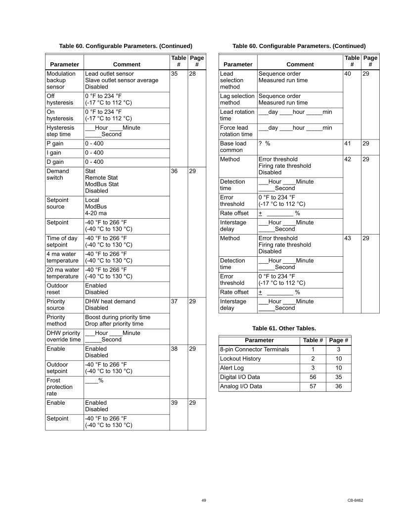
Modulation backup sensor
Lead outlet sensorSlave outlet sensor averageDisabled
35 28
Off hysteresis
0 °F to 234 °F(-17 °C to 112 °C)
On hysteresis
0 °F to 234 °F(-17 °C to 112 °C)
Hysteresis step time
___Hour ____Minute _____Second
P gain 0 - 400I gain 0 - 400D gain 0 - 400Demand switch
StatRemote StatModBus StatDisabled
36 29
Setpoint source
LocalModBus4-20 ma
Setpoint -40 °F to 266 °F (-40 °C to 130 °C)
Time of day setpoint
-40 °F to 266 °F (-40 °C to 130 °C)
4 ma water temperature
-40 °F to 266 °F (-40 °C to 130 °C)
20 ma water temperature
-40 °F to 266 °F (-40 °C to 130 °C)
Outdoor reset
EnabledDisabled
Priority source
DHW heat demandDisabled
37 29
Priority method
Boost during priority timeDrop after priority time
DHW priority override time
___Hour ____Minute _____Second
Enable EnabledDisabled
38 29
Outdoor setpoint
-40 °F to 266 °F (-40 °C to 130 °C)
Frost protection rate
____%
Enable EnabledDisabled
39 29
Setpoint -40 °F to 266 °F (-40 °C to 130 °C)
Table 60. Configurable Parameters. (Continued)
Parameter CommentTable
#Page
#Lead selection method
Sequence orderMeasured run time
40 29
Lag selection method
Sequence orderMeasured run time
Lead rotation time
___day ____hour _____min
Force lead rotation time
___day ____hour _____min
Base load common
? % 41 29
Method Error thresholdFiring rate thresholdDisabled
42 29
Detection time
___Hour ____Minute _____Second
Error threshold
0 °F to 234 °F(-17 °C to 112 °C)
Rate offset + ________ %Interstage delay
___Hour ____Minute _____Second
Method Error thresholdFiring rate thresholdDisabled
43 29
Detection time
___Hour ____Minute _____Second
Error threshold
0 °F to 234 °F(-17 °C to 112 °C)
Rate offset + ________ %Interstage delay
___Hour ____Minute _____Second
Table 61. Other Tables.
Parameter Table # Page #8-pin Connector Terminals 1 3Lockout History 2 10Alert Log 3 10Digital I/O Data 56 35Analog I/O Data 57 36
Table 60. Configurable Parameters. (Continued)
Parameter CommentTable
#Page
#
49 CB-8462
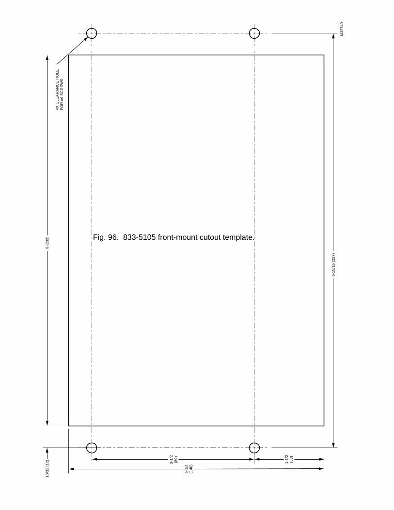
M32
740
4X C
LEA
RA
NC
E H
OLE
FOR
#6
SC
RE
WS
8 (2
03)
8-15
/16
(227
)
15/3
2 (1
2)
5-1/
2(1
40)3-
1/2
(89)
1-1/
2(3
8)
Fig. 96. 833-5105 front-mount cutout template.
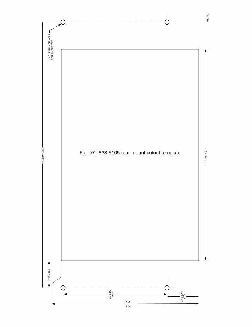
7-1/
8 (1
81)
8-15
/16
(227
)
4X C
LEA
RA
NC
E H
OLE
FOR
#6
SC
RE
WS
29/3
2 (2
3)
4-41
/64
(118
)
2X 3
-1/2
(89)
2X 1
-5/6
4(2
7)
M32
741
Fig. 97. 833-5105 rear-mount cutout template.

APPENDIX C
Gas Valve


Product data
EN2R-9074 0612R1-NE
V4730C/V8730C/V4734C1:1 Gas/Air Servo Regulated Gas Valves
Note: Photo shows valve with manual safety shutoff valve andventuri installed.
CONTENTSApplication ..........................................................1
Features ..............................................................1
Specifications ......................................................2
Ordering Information.............................................3
Installation ..........................................................13
Electrical Connections ........................................14
Adjustments and Final Checkout ........................14
Operation ...........................................................15
Troubleshooting..................................................16
Service Information ............................................16
APPLICATIONThe V4730C/V8730C/V4734C 1:1 Gas/Air Servo Regulated Gas Valves, with the addition of the Venturi Mixing Unit (VMU) and dc fan, are used for modulating premix appliances such as gas bur-ners, gas boilers, rooftop units, makeup air units and process ap-plications.
FEATURES• Wide modulation range (14% to 100% of burner load).
• 24 Vac and 120 Vac models.
• Main valve body with two shutoff seats (double block valve).
• Closing time less than one second.
• Mesh screen (strainer) between inlet flange and main body.
• Various pressure tap points available at main body when no additional valves or pressure switches are used.
• DIN 43650 Plug Connector with 36-in. (914 mm) leadwires included.
• Flexible mounting positions of venturi manifold to fan.
• Replaceable pipe flange adapters available.
• Position indication lamp for each valve stage
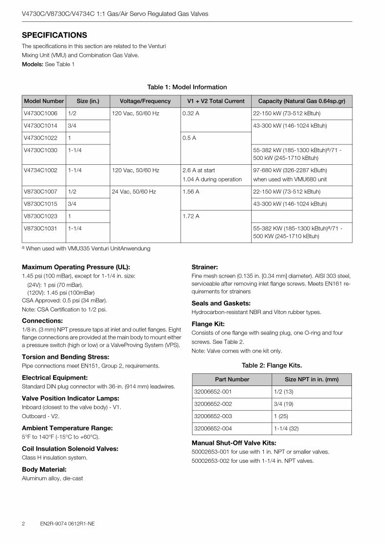
V4730C/V8730C/V4734C 1:1 Gas/Air Servo Regulated Gas Valves
2 EN2R-9074 0612R1-NE
SPECIFICATIONSThe specifications in this section are related to the Venturi
Mixing Unit (VMU) and Combination Gas Valve.
Models: See Table 1
a When used with VMU335 Venturi UnitAnwendung
Table 1: Model Information
Model Number Size (in.) Voltage/Frequency V1 + V2 Total Current Capacity (Natural Gas 0.64sp.gr)
V4730C1006 1/2 120 Vac, 50/60 Hz 0.32 A 22-150 kW (73-512 kBtuh)
V4730C1014 3/4 43-300 kW (146-1024 kBtuh)
V4730C1022 1 0.5 A
V4730C1030 1-1/4 55-382 kW (185-1300 kBtuh)a/71 - 500 kW (245-1710 kBtuh)
V4734C1002 1-1/4 120 Vac, 50/60 Hz 2.6 A at start
1.04 A during operation
97-680 kW (326-2287 kButh)
when used with VMU680 unit
V8730C1007 1/2 24 Vac, 50/60 Hz 1.56 A 22-150 kW (73-512 kBtuh)
V8730C1015 3/4 43-300 kW (146-1024 kBtuh)
V8730C1023 1 1.72 A
V8730C1031 1-1/4 55-382 KW (185-1300 kBtuh)a/71 - 500 KW (245-1710 kBtuh)
Maximum Operating Pressure (UL):1.45 psi (100 mBar), except for 1-1/4 in. size:
(24V): 1 psi (70 mBar).(120V): 1.45 psi (100mBar)
CSA Approved: 0.5 psi (34 mBar).
Note: CSA Certification to 1/2 psi.
Connections:1/8 in. (3 mm) NPT pressure taps at inlet and outlet flanges. Eight flange connections are provided at the main body to mount either a pressure switch (high or low) or a ValveProving System (VPS).
Torsion and Bending Stress:Pipe connections meet EN151, Group 2, requirements.
Electrical Equipment:Standard DIN plug connector with 36-in. (914 mm) leadwires.
Valve Position Indicator Lamps:Inboard (closest to the valve body) - V1.
Outboard - V2.
Ambient Temperature Range:5°F to 140°F (-15°C to +60°C).
Coil Insulation Solenoid Valves:Class H insulation system.
Body Material:Aluminum alloy, die-cast
Strainer:Fine mesh screen (0.135 in. [0.34 mm] diameter). AISI 303 steel, serviceable after removing inlet flange screws. Meets EN161 re-quirements for strainers
Seals and Gaskets:Hydrocarbon-resistant NBR and Viton rubber types.
Flange Kit:Consists of one flange with sealing plug, one O-ring and four
screws. See Table 2.
Note: Valve comes with one kit only.
Manual Shut-Off Valve Kits:50002653-001 for use with 1 in. NPT or smaller valves.
50002653-002 for use with 1-1/4 in. NPT valves.
Table 2: Flange Kits.
Part Number Size NPT in in. (mm)
32006652-001 1/2 (13)
32006652-002 3/4 (19)
32006652-003 1 (25)
32006652-004 1-1/4 (32)

V4730C/V8730C/V4734C 1:1 Gas/Air Servo Regulated Gas Valves
EN2R-9074 0612R1-NE 3
ORDERING INFORMATIONWhen purchasing replacement and modernization products from your TRADELINE® wholesaler or distributor, refer to the TRADELINE® Catalog or price sheets for complete ordering number. If you have additional questions, need further informati-on, or would like to comment on our products or services, please write or phone:
1. Your local Honeywell Automation and Control Products Sales Office (check white pages of your phone directory).
2. Honeywell Customer Care1885 Douglas Drive North
Minneapolis, Minnesota 55422-4386
In Canada - Honeywell Limited/Honeywell Limitée, 35 Dynamic Drive, Scarborough, Ontario M1V 4Z9.
International Sales and Service Offices in all principal cities of the world. Manufacturing in Australia, Canada, Finland, France, Ger-many, Japan, Mexico, Netherlands, Spain, Taiwan, United King-dom, U.S.A.
Opening Time:Dead time maximum: 1 second.
First valve opening: less than 1 second.
Second valve opening: reaches 50% of the adjustable outlet pressure within 5 seconds.
Maximum Allowable Leakage:Outerwall: 3 cu. in./hr (50 cm3/h) at test pressure of 0.87 psi
(6 mBar) and 7.83 psi (540 mBar).
First Valve: 2.5 cu. in./hr (40 cm3/h) at test pressure of 0.87 psi (6 mBar) and 7.83 psi (540 mBar).
Second Valve: 2.4 cu. in./hr (40 cm3/h) at test pressure of 0.87 psi (6 mBar) and 7.83 psi (540 mBar).
High Pressure Test:In the OFF condition, the valve will withstand 21.75 psi (1.5 Bar) inlet pressure without damage.
Accessories:FL020008 Mesh Screen.Flange Kits (see Table 2).DIN43650 Connector32006653-001 Venturi O-rings/screws.
Operational Voltage Range:The combination gas valve will function satisfactorily between 85% and 110% of the rated voltage.
Gas Valve Connection to Venturi (Field-Assembled):Four screws and an O-ring are used to connect the gas valve to the venturi/manual shutoff valve. The metal tube provided with the venturi must be connected bet-ween the venturi and the gas valve regulator.
Fan Connection:The venturi is connected to the fan using six bolts (wich are inclu-ded with VMU).
Minimum Load:The minimum load for which the system can be used is
14-17% of the reference load, which equals a minimum
pressure differential of 0.2 in. wc (50 Pa) of the 1:1
venturi/servo regulator gas control.
Approvals:Gas Appliance Directive 90.396/EEC
ANSI: Z21.21
CSA: 6.5
Capacity Curves:
See Fig. 9 to 14.
Dimensions:See Fig. 1 to 5
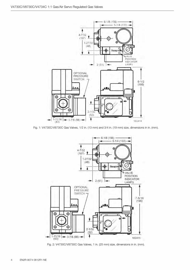
V4730C/V8730C/V4734C 1:1 Gas/Air Servo Regulated Gas Valves
4 EN2R-9074 0612R1-NE
Fig. 1: V4730C/V8730C Gas Valves, 1/2 in. (13 mm) and 3/4 in. (19 mm) size, dimensions in in. (mm).
Fig. 2: V4730C/V8730C Gas Valves, 1 in. (25 mm) size, dimensions in in. (mm).
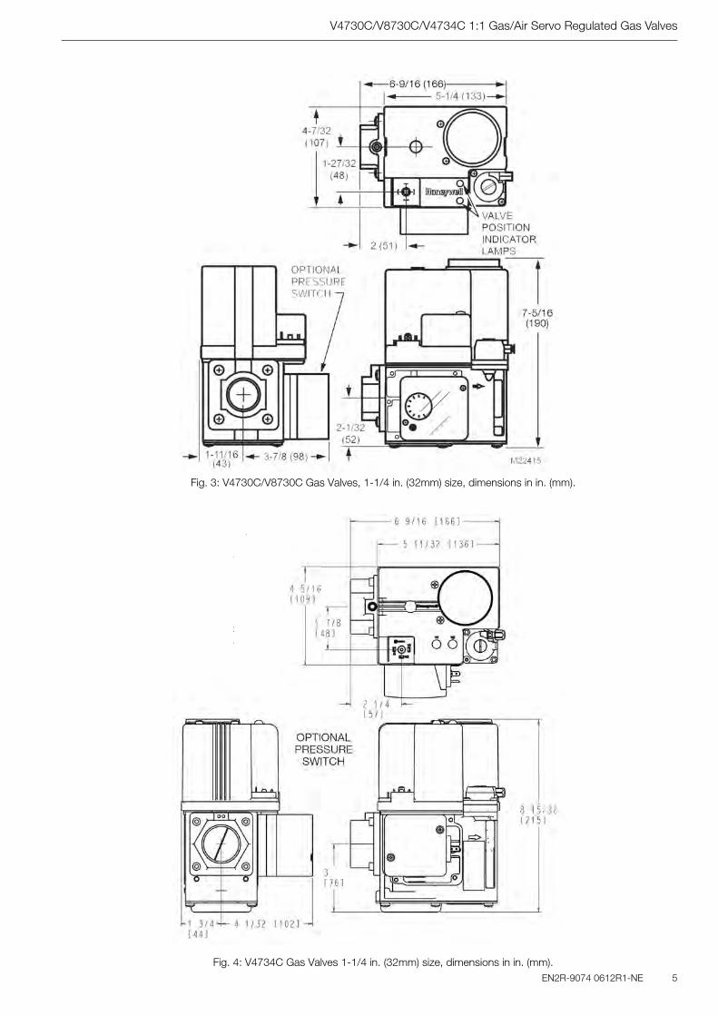
V4730C/V8730C/V4734C 1:1 Gas/Air Servo Regulated Gas Valves
EN2R-9074 0612R1-NE 5
Fig. 3: V4730C/V8730C Gas Valves, 1-1/4 in. (32mm) size, dimensions in in. (mm).
Fig. 4: V4734C Gas Valves 1-1/4 in. (32mm) size, dimensions in in. (mm).
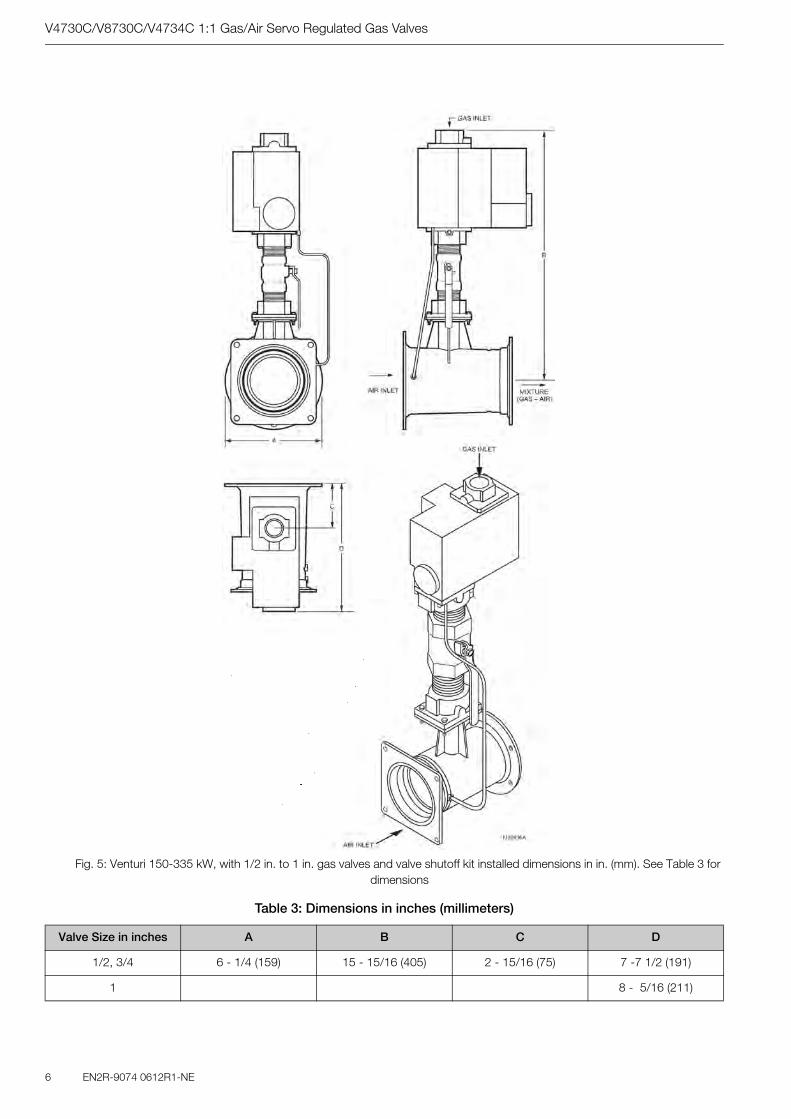
V4730C/V8730C/V4734C 1:1 Gas/Air Servo Regulated Gas Valves
6 EN2R-9074 0612R1-NE
Fig. 5: Venturi 150-335 kW, with 1/2 in. to 1 in. gas valves and valve shutoff kit installed dimensions in in. (mm). See Table 3 for dimensions
Table 3: Dimensions in inches (millimeters)
Valve Size in inches A B C D
1/2, 3/4 6 - 1/4 (159) 15 - 15/16 (405) 2 - 15/16 (75) 7 -7 1/2 (191)
1 8 - 5/16 (211)
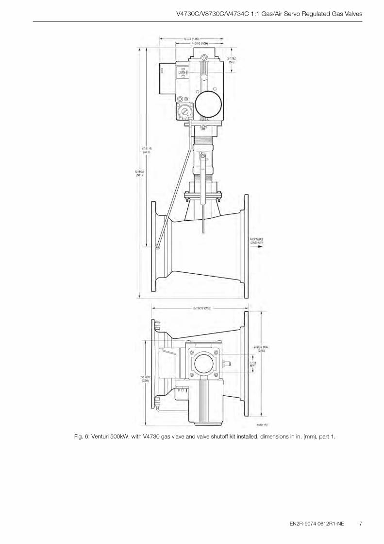
V4730C/V8730C/V4734C 1:1 Gas/Air Servo Regulated Gas Valves
EN2R-9074 0612R1-NE 7
Fig. 6: Venturi 500kW, with V4730 gas vlave and valve shutoff kit installed, dimensions in in. (mm), part 1.
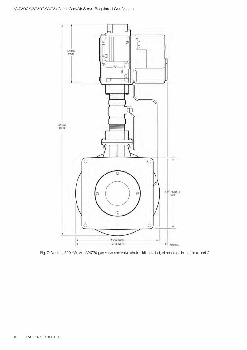
V4730C/V8730C/V4734C 1:1 Gas/Air Servo Regulated Gas Valves
8 EN2R-9074 0612R1-NE
Fig. 7: Venturi, 500 kW, with V4730 gas valve and valve shutoff kit installed, dimensions in in. (mm), part 2
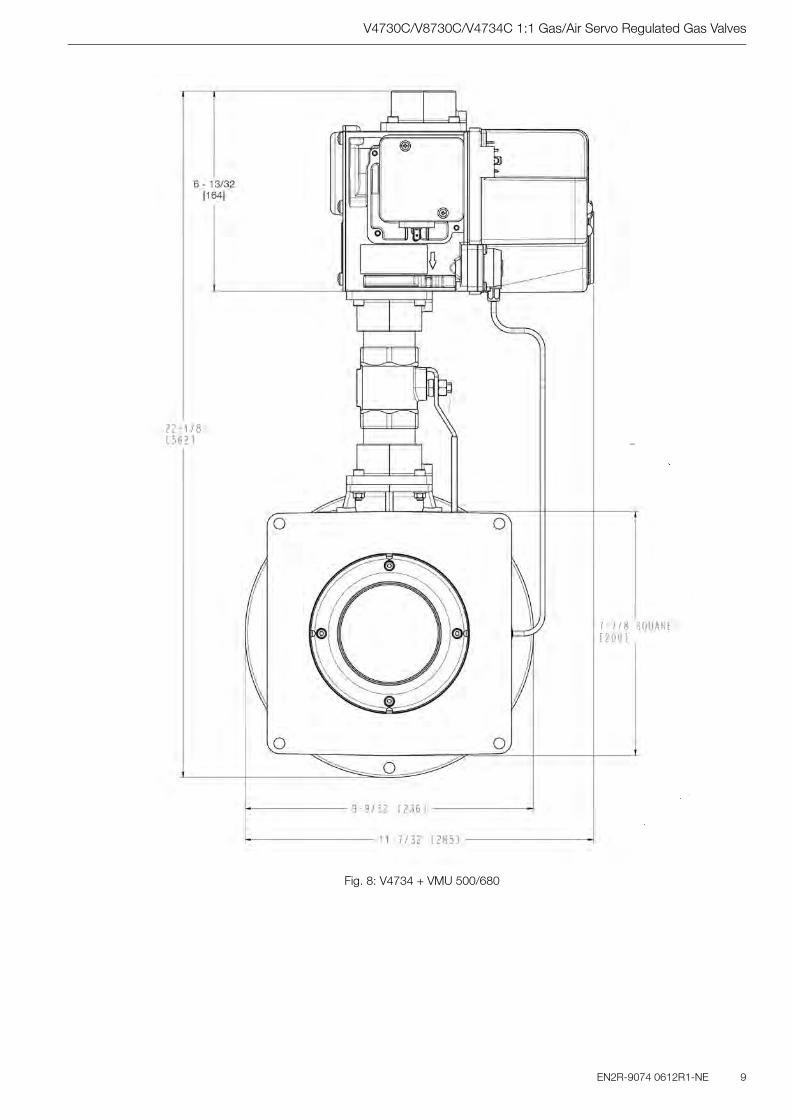
V4730C/V8730C/V4734C 1:1 Gas/Air Servo Regulated Gas Valves
EN2R-9074 0612R1-NE 9
Fig. 8: V4734 + VMU 500/680

V4730C/V8730C/V4734C 1:1 Gas/Air Servo Regulated Gas Valves
10 EN2R-9074 0612R1-NE
Fig. 9: Capacity curves for V4730C/V8730C and VMU 150 Venturi, 1/2 in. size.
Fig. 10: Capacity curves for V4730C/V8730C and VMU 300 Venturi, 3/4 in. size

V4730C/V8730C/V4734C 1:1 Gas/Air Servo Regulated Gas Valves
EN2R-9074 0612R1-NE 11
Fig. 11: Capacity curves for V4730C/V8730C and VMU 300 Venturi, 1 in. size.
Fig. 12: Capacity curves for V4730C/V8730C and VMU 335 Venturi, 1-1/4 in. size.
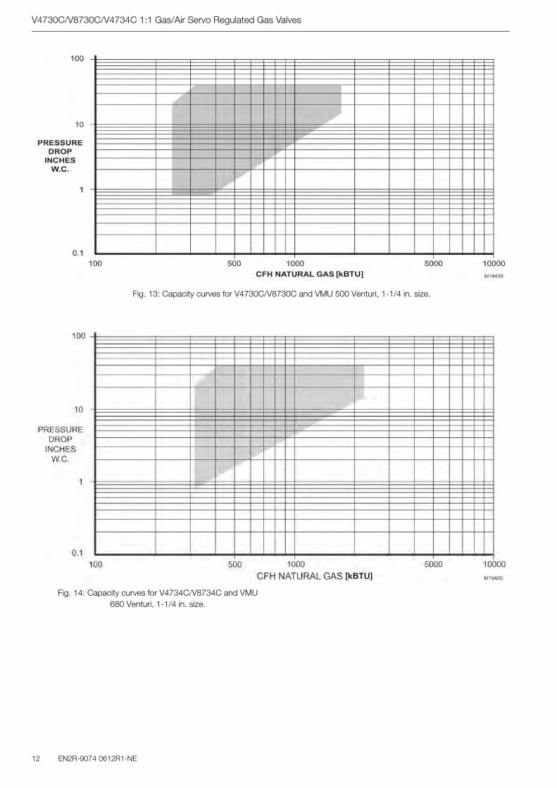
V4730C/V8730C/V4734C 1:1 Gas/Air Servo Regulated Gas Valves
12 EN2R-9074 0612R1-NE
Fig. 14: Capacity curves for V4734C/V8734C and VMU 680 Venturi, 1-1/4 in. size.
Fig. 13: Capacity curves for V4730C/V8730C and VMU 500 Venturi, 1-1/4 in. size.
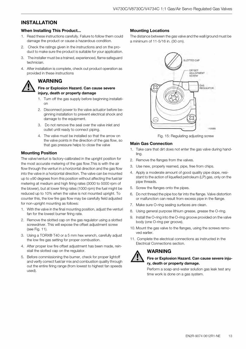
V4730C/V8730C/V4734C 1:1 Gas/Air Servo Regulated Gas Valves
EN2R-9074 0612R1-NE 13
INSTALLATION
When Installing This Product...1. Read these instructions carefully. Failure to follow them could
damage the product or cause a hazardous condition.
2. Check the ratings given in the instructions and on the pro-duct to make sure the product is suitable for your application.
3. The installer must be a trained, experienced, flame safeguard technician.
4. After installation is complete, check out product operation as provided in these instructions
Mounting PositionThe valve/venturi is factory-calibrated in the upright position for the most accurate metering of the gas flow.This is with the air flow through the venturi in a horizontal direction and the gas flow into the valve in a horizontal direction. The valve can be mounted up to ±90 degrees from this position without affecting the fuel/air metering at medium and high firing rates (3000 to 5000 rpm of the blower), but at lower firing rates (1000 rpm) the fuel might be reduced up to 10% when the valve is not mounted upright. To counter this, the low fire gas flow may be carefully field adjusted for non-upright mounting as follows:
1. With the valve in the final mounting position, adjust the venturifan for the lowest burner firing rate.
2. Remove the slotted cap on the gas regulator using a slotted screwdriver. This will expose the offset adjustment screw (see Fig. 11).
3. Using a TORX® T40 or a 5 mm hex wrench, carefully adjust the low fire gas setting for proper combustion.
4. After proper low fire offset adjustment has been made, rein-stall the slotted cap on the regulator.
5. Before commissioning the burner, check for proper lightoff and verify correct fuel/air mix and combustion quality through out the entire firing range (from lowest to highest fan speeds used).
Mounting LocationsThe distance between the gas valve and the wall/ground must be a minimum of 11-5/16 in. (30 cm).
Fig. 15: Regulating adjusting screw
Main Gas Connection1. Take care that dirt does not enter the gas valve during hand-
ling.
2. Remove the flanges from the valves.
3. Use new, properly reamed, pipe, free from chips.
4. Apply a moderate amount of good quality pipe dope, resi-stant to the action of liquefied petroleum (LP) gas, only on the pipe threads.
5. Screw the flanges onto the pipes.
6. Do not thread the pipe too far into the flange. Valve distortion or malfunction can result from excess pipe in the flange.
7. Make sure O-ring sealing surfaces are clean.
8. Using general purpose lithium grease, grease the O-ring.
9. Install the O-ring into the O-ring groove provided on the valve body (one O-ring per groove).
10. Mount the gas valve to the flanges, using the screws remo-ved earlier.
11. Complete the electrical connections as instructed in the Electrical Connections section.
WARNINGFire or Explosion Hazard. Can cause severe injury, death or property damage
1. Turn off the gas supply before beginning installati-on
2. Disconnect power to the valve actuator before be-ginning installation to prevent electrical shock and damage to the equipment.
3. Do not remove the seal over the valve inlet and outlet until ready to connect piping.
4. The valve must be installed so that the arrow on the valve points in the direction of the gas flow, so that gas pressure helps to close the valve
WARNINGFire or Explosion Hazard. Can cause severe inju-ry, death or property damage.
Perform a soap-and-water solution gas leak test any time work is done on a gas system.

V4730C/V8730C/V4734C 1:1 Gas/Air Servo Regulated Gas Valves
EN2R-9074 0612R1-NE
ELECTRICAL CONNECTIONS
Wiring1. Use 14, 16 or 18 AWG copper conductor, 600 volt insulation,
moisture-resistant wire for line voltage connections. Recom-mended wire types are TTW60C, THW75C or THHN90C.
2. Follow the instructions below for wiring the gas valve. See Fig. 16 and 17 for reference.
2.a T1 (yellow) will be L2 (120 Vac or 24 Vac).
2.b T2 (black) will be L1 (120 Vac or 24 Vac) to Valve 1.
2.c T3 (blue) will be L1 (120 Vac or 24 Vac) to Valve 2.
2.d Ground (green) will be earth ground.
Fig. 16: Four-pin electrical plug connector
Fig. 17: Electrical connection diagram
WARNINGElectrical Shock Hazard. Can cause severe injury or death.
Disconnect the power supply before beginning wiring to prevent electrical shock. More than one disconnect may be involved.
ADJUSTMENTS AND FINAL CHECKOUTThe following procedures are related to the adjustments on the main gas valve. For adjustments of the other devices (i.e., pres-sure switches), refer to the instructions supplied with the applica-ble device.
Pressure Tap Points (Fig. 18)The V4730C/V8730C/V4734C Valves have a number of connec-tion points (1/8 in. [3 mm] NPT plugs) for measuring pressure and/or mounting a pressure switch. The pressure tap points are:
1 inlet pressure at first SSOV flange tap.2 inlet pressure at first SSOV.P outlet pressure at first SSOV.3 inlet pressure at second SSOV.4 outlet pressure at second SSOV flange tap.
The following pressures can be measured:
1. Inlet pressure-tap on inlet flange (1).
2. Pressure after inlet screen (2).
3. Unregulated intermediate pressure-pressure between the two shutoff seats (P).
4. Regulated intermediate pressure-pressure between the shu-toff valves (3).
5. Outlet pressure-tap from flange (4).
The corresponding numbers (2, P, 3) can be found on the side of the valve.
Note: To mount the C6097 Pressure Switch, refer to instructionsin form number 65-0237, furnished with the switch. Thepressure switch can be mounted to 2, P, or 3 on eitherside of the valve.
Fig. 18: Pressure tap points
Second Valve, Fast OpeningFlow rate is adjusted from 0% to 100% of full rated flow. To ad-just the flow rate:
1. Remove the flat, round, blue plastic cap from the cover.Using a 3 mm (7/64 in.) hex wrench, turn the adjustmentscrew counterclockwise to increase or clockwise to decreasethe flow rate.
2. Snap the flat, round, blue plastic cap back onto the cover.
Final Checkout of the InstallationSet the system in operation after any adjustment is completed and observe several complete cycles to ensure that all burner components function correctly.
WARNINGFire or Explosion Hazard.
Can cause severe injury, death or property da-mage.
Only fully qualified, experienced, flame safeguard technicians should make adjustments on the valve.
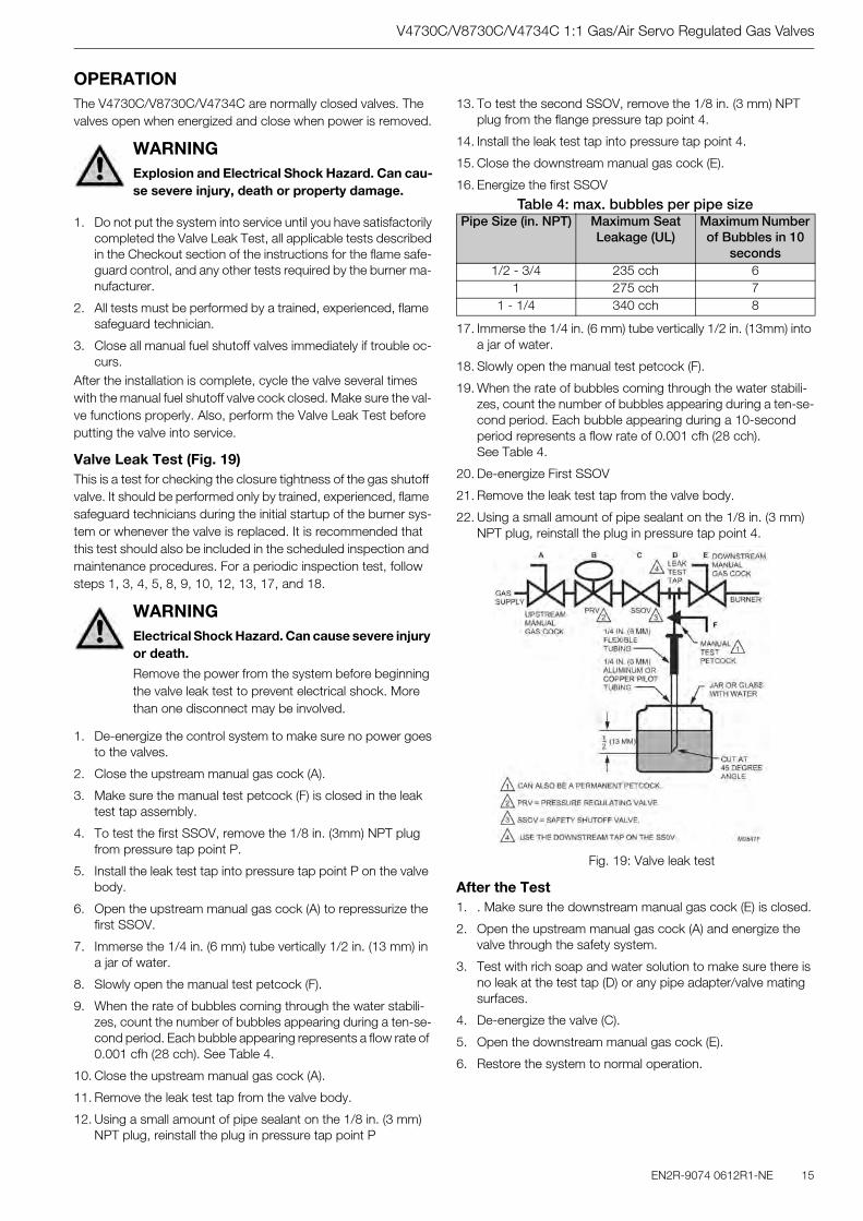
V4730C/V8730C/V4734C 1:1 Gas/Air Servo Regulated Gas Valves
EN2R-9074 0612R1-NE 15
OPERATIONThe V4730C/V8730C/V4734C are normally closed valves. The valves open when energized and close when power is removed.
1. Do not put the system into service until you have satisfactorilycompleted the Valve Leak Test, all applicable tests describedin the Checkout section of the instructions for the flame safe-guard control, and any other tests required by the burner ma-nufacturer.
2. All tests must be performed by a trained, experienced, flame safeguard technician.
3. Close all manual fuel shutoff valves immediately if trouble oc-curs.
After the installation is complete, cycle the valve several times with the manual fuel shutoff valve cock closed. Make sure the val-ve functions properly. Also, perform the Valve Leak Test before putting the valve into service.
Valve Leak Test (Fig. 19)This is a test for checking the closure tightness of the gas shutoff valve. It should be performed only by trained, experienced, flame safeguard technicians during the initial startup of the burner sys-tem or whenever the valve is replaced. It is recommended that this test should also be included in the scheduled inspection and maintenance procedures. For a periodic inspection test, follow steps 1, 3, 4, 5, 8, 9, 10, 12, 13, 17, and 18.
1. De-energize the control system to make sure no power goesto the valves.
2. Close the upstream manual gas cock (A).
3. Make sure the manual test petcock (F) is closed in the leak test tap assembly.
4. To test the first SSOV, remove the 1/8 in. (3mm) NPT plug from pressure tap point P.
5. Install the leak test tap into pressure tap point P on the valve body.
6. Open the upstream manual gas cock (A) to repressurize the first SSOV.
7. Immerse the 1/4 in. (6 mm) tube vertically 1/2 in. (13 mm) in a jar of water.
8. Slowly open the manual test petcock (F).
9. When the rate of bubbles coming through the water stabili-zes, count the number of bubbles appearing during a ten-se-cond period. Each bubble appearing represents a flow rate of 0.001 cfh (28 cch). See Table 4.
10. Close the upstream manual gas cock (A).
11. Remove the leak test tap from the valve body.
12. Using a small amount of pipe sealant on the 1/8 in. (3 mm) NPT plug, reinstall the plug in pressure tap point P
13. To test the second SSOV, remove the 1/8 in. (3 mm) NPT plug from the flange pressure tap point 4.
14. Install the leak test tap into pressure tap point 4.
15. Close the downstream manual gas cock (E).
16. Energize the first SSOV
Table 4: max. bubbles per pipe size
17. Immerse the 1/4 in. (6 mm) tube vertically 1/2 in. (13mm) into a jar of water.
18. Slowly open the manual test petcock (F).
19. When the rate of bubbles coming through the water stabili-zes, count the number of bubbles appearing during a ten-se-cond period. Each bubble appearing during a 10-second period represents a flow rate of 0.001 cfh (28 cch). See Table 4.
20. De-energize First SSOV
21. Remove the leak test tap from the valve body.
22. Using a small amount of pipe sealant on the 1/8 in. (3 mm) NPT plug, reinstall the plug in pressure tap point 4.
Fig. 19: Valve leak test
After the Test1. . Make sure the downstream manual gas cock (E) is closed.
2. Open the upstream manual gas cock (A) and energize the valve through the safety system.
3. Test with rich soap and water solution to make sure there is no leak at the test tap (D) or any pipe adapter/valve mating surfaces.
4. De-energize the valve (C).
5. Open the downstream manual gas cock (E).
6. Restore the system to normal operation.
WARNINGExplosion and Electrical Shock Hazard. Can cau-se severe injury, death or property damage.
WARNINGElectrical Shock Hazard. Can cause severe injury or death.
Remove the power from the system before beginning the valve leak test to prevent electrical shock. More than one disconnect may be involved.
Pipe Size (in. NPT) Maximum Seat Leakage (UL)
Maximum Number of Bubbles in 10
seconds1/2 - 3/4 235 cch 6
1 275 cch 71 - 1/4 340 cch 8

Automation & Control SolutionsCombustion Controls EuropeHoneywell BVPhileas Foggstraat 77821 AJ EmmenThe NetherlandsTel.: +31 (-) 591 695911Fax.: +31 (-) 591 695200http://europe.hbc.honeywell.com
V4730C/V8730C/V4734C 1:1 Gas/Air Servo Regulated Gas Valves
Manufactured for and on behalf of the Environment and Combustion ControlsDivision of Honeywell Technologies Sàrl,Ecublens, Route du Bois 37, Switzerlandby its Authorised Representative.
Subject to change without notice© 2006 Automation & Control SolutionsCombustion Controls Europe
TROUBLESHOOTING
Troubleshooting ProcedureIf the valve does not open when the thermostat or controller
calls for heat:
1. Check for voltage at the valve leadwires or terminal block.
2. If there is no voltage at the valve leadwires or terminal block, make sure:
2.a voltage is connected to the master switch.
2.b master switch is closed and overload protection (circuit breaker, fuse, or similar device) has notopened the po-wer line.
3. If there is still no voltage at the valve leadwires or terminal block, make sure all appropriate contacts in the thermostat or controller, limits and flame safeguard control are closed. If one or more are open, determine the cause(s); correct the trouble and proceed.
4. If there is proper voltage at the valve but the valve still does not open, check for normal gas pressure.
5. If the valve still does not open, replace the valve.
If the valve does not close when one or more of the appropriate contacts in the thermostat, controller, limits or flame safeguard control is open:
1. Make sure the valve is wired in the correct circuit.
2. Open the master switch to remove power from the valve.
3. If the valve closes now, check the wiring for the valve and cor-rect the wiring as necessary.
4. Check for a short in the electrical circuit and repair it as ne-cessary.
WARNINGElectrical Shock Hazard. Can cause severe inju-ry, death or property damage.
Use extreme caution when troubleshooting; line volta-ge is present.
IMPORTANTDo not replace the valve until all other sources of trouble are eliminated.
SERVICE INFORMATION
Scheduled Inspection and Maintenance
Set up and follow a schedule for periodic inspection and mainte-nance, including the burner, all other controls and the valves. It is recommended that the valve leak test in the Checkout section be included in this schedule. Refer to the instructions for the primary safety control (s) 0 for more inspection and maintenance informa-tion.
Screen/Strainer Replacement1. Make sure the gas supply is turned off and all electrical
power has been removed.
2. Remove bolts/nuts from flange/valve.
3. Remove flange from gas supply pipe.
4. Remove old screen/strainer.
5. Clean the strainer by using compressed air, or replace the strainer.
6. Install the cleaned strainer or new strainer.
7. Make sure O-ring sealing surface is clean on the flange.
8. Using general purpose lithium grease, grease the O-ring.
9. Apply a moderate amount of good quality pipe dope, resi-stant to the action of LP gas, only on the pipe threads.
10. Install the O-ring in the O-ring groove provided on the flange/valve body (one O-ring per groove).
11. Screw the flange onto the pipe.
12. Mount the gas valve to the flange, using the bolts and nuts for each flange.
13. Apply power to the valve.
14. Turn on the main gas supply.
15. Complete the valve leak test.
16. Return the valve to service.
WARNINGExplosion Hazard and Electrical Shock Hazard. Can cause severe injury, death or property da-mage.
Turn off gas supply and disconnect all electrical power to the valve before servicing.
IMPORTANTOnly trained, experienced, flame safeguard technici-ans should attempt to service or repair flame safe-guard controls and burner assemblies.
EN0H-0281NL05-R1006

34

e-mail: [email protected] Address: http://www.cleaverbrooks.com