Embed Size (px)
Citation preview

Model Based Safety Analysis
R&D Division of Safety Critical Systems
Fachbereich InformatikAbt. Sicherheitskritische Eingebettete Systeme
Werner Damm & Thomas Peikenkamp

Model Based Safety Analysis Werner Damm – all rights reserved
Structure of Presentation
• Introduction• Model Based Development• Safety Analysis Process• Model Based Safety Analysis• Conclusion

Model Based Safety Analysis Werner Damm – all rights reserved
Introduction

Model Based Safety Analysis Werner Damm – all rights reserved
A380
FlightControl
Utilities
Cockpit
AESU1
EHM1
EHM2
EEC1
EEC2
FCSC1COM MON
FCSC2FCGC2
FCGC3
SFCC2
COM MONCOM MONSFCC1
FCGC1
ADIRU1
ADIRU3
ADIRU2
FM3
FM2FM1
FW2FCDC2
FW1FCDC1
AESU2
ACR2 opt
SCI
L1 L2 R2 R1
C2 R3
C1EEC4
EHM4
EEC3
EHM3
SW13
IOM
ELMCBMSB24
ELMCBMSB24
FuelCOM MON
FuelLG,TP&BSCOM MON
CIDS
Ventil °&press
CIDS
IRDC
COM MONLG,TP&BS
COM MON
COM MON COM MON COM MON
IOM
ACR1
SCI
Air conditioning
PESC
SPDB
IPCU
SPDB
VSCPWCU
IRDC
doors ctrl,oxygen ctrl
ext lightsctrl
IPCU
ECB
HSMAIC?
HSMAIC?
COM MONFCSC3 TBCCOM MON
L3
IOMIOM ACMFFDIF
ATC1 ATC2
Ventil °&press Air conditioningimplementation TBD
Engines
OpenWorld
A380: about 100 functions realized in SW, total code size ~65 MB

Model Based Safety Analysis 5Werner Damm – all rights reserved
Outboard InboardAilerons
OutboardInboardAilerons
Spoilers Spoilers
Y G B GG YG B
Y G Y B B G G B B Y G Y
G Y
B G
Flaps
Slats
Elevator Elevator
B G G Y
B Y
Trimmable horizontal stabilizer
Y
G
B
Trim
G
Y
S1 S2
P1 S1
P3 S2
Rudder
S1
S2Rudderpedals
P2 P1S2 S1
P1 P2S1 S2
1 2 3
P1 P2 P3
Trim wheels
P3 S1 P1 P2S1 S2
P1 P2 S2 P3S1 S2
S1 P1 P2 S2 P3 P3 P3 P3 S2 P2 P1 S1
Y
G
B Blue
Green
Yellow
hydraulicsupply
P1, P2, P3 Primarycomputers
S1, S2 Secondarycomputers
(Underscore indicates priority)
The high-lift system
© N.S.

Model Based Safety Analysis Werner Damm – all rights reserved
Sample application: Slat and Flap system

Model Based Safety Analysis Werner Damm – all rights reserved
System Architecture
• Auto-Flap function– Automatically adjusts
flap position according to load
• Critical Events– Asymmetric Flap
Position– Powered runaway– Inadvertent Flap
Retract due to Auto-Flap Function
• Extensive Monitoring– To detect critical
eventsFlap-Controller

Model Based Safety Analysis Werner Damm – all rights reserved
Model Based Development of Avionics Applications

Model Based Safety Analysis Werner Damm – all rights reserved
Model based Development Process
Aircraft level
System level
Equipment level
Requirement“For the current flaps setting, CAS shall not exceed VF.”
Specification
Implementation
Analysis
Modeling
Test
Iterative Prototype *
FlightControl
Utilities
Cockpit
AESU1
EHM1
EHM2
EEC1
EEC2
FCSC1COM MON FCSC2FCGC2FCGC3
SFCC2COM MONCOM MON
SFCC1FCGC1
ADIRU1ADIRU3
ADIRU2FM3
FM2FM1
FW2FCDC2FW1FCDC1
AESU2
ACR2 opt
SCI
L1L2 R2R1C2R3C1 EEC4
EHM4
EEC3EHM3
SW13IOM
ELMCBMSB24ELMCBMSB24FuelCOM MON
FuelLG,TP&BSCOM MON
CIDS
Ventil°&press
CIDSIRDC
COM MONLG,TP&BSCOM MON
COM MON COM MONCOM MON
IOM
ACR1
SCI
Air conditioning
PESC
SPDB
IPCU
SPDB
VSCPWCU IRDC
doors ctrl,oxygen ctrl
ext lightsctrl
IPCU
ECB
HSMAIC? HSMAIC?
COM MONFCSC3 TBCCOM MON
L3
IOMIOM ACMFFDIF
ATC1 ATC2
Ventil°&press Air conditioningimplementation TBD
Engines
OpenWorld
Model Based Safety Analysis Werner Damm – all rights reserved
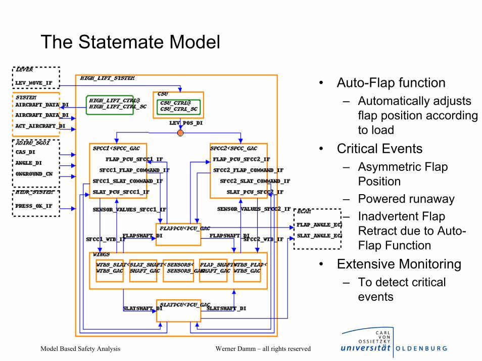
The Statemate Model
• Auto-Flap function– Automatically adjusts
flap position according to load
• Critical Events– Asymmetric Flap
Position– Powered runaway– Inadvertent Flap
Retract due to Auto-Flap Function
• Extensive Monitoring– To detect critical
events

Model Based Safety Analysis Werner Damm – all rights reserved
STATEMATE
• Industry standard case tool marketed by I-Logix Inc
• Activity Charts– System Architecture– Information Flow– Environment
• State Charts– visual real-time
programming language– hierarchy– orthogonal states– algorithms
• Animation• Simulation• RP code generation• documentation
Formal published semanticsDamm, Pnueli, … 98

Model Based Safety Analysis Werner Damm – all rights reserved
A sample StateChart

Model Based Safety Analysis Werner Damm – all rights reserved
Example: Model characteristics
• Static measures– 30 charts, most instances of
generic charts– 164 data-items (mostly floats)– 38 conditions, 12 events– Arrays, records, user defined
types– 7 timers
• Explicit representation as flat finite state machine would require 35 000 states
• Exhaustive testing would require to cover 275 possible input values in each step
ERROR_EV
AUTO_CMD CHK_POS_THRESH CHK_LEVER
MONITORING
MOVEMENT_CMD
ADIRU_DATA_IF(Air Data)
IN_FPPU_DI (Feedback Position)
IN_APPU_IF (Asymmetry Position
(Other Flap Sensors)
Dis
Re
IN_LEV_POS_DI (FLAP Lever Position)
IN_PSWITCH_DI (Pressure Switch)
Dis
Re
Re
Re
OUT_RETRACT_DI
OUT_POB_DI (Pressure Off Brake)
OUT_SET_WTB_CN (Wing Tip Brake)
(System Errors)
Dis
OUT_HIGHSPEED_DI
OUT_EXTEND_DI
Dis
Dis
Dis
Dis
Dis
POS_THRESH_CN
EX
TEN
D_E
V
SH
UTD
OW
N_E
V
TUR
NA
RO
UN
D_C
N
RE
TRA
CT_
EV
R
EA
CH
ED
_EV
CMD_SET_EVNEW_CMD_EV CONTINUE_CMD_EV
BR
EA
K_E
V
INH
IBIT
_STA
RTU
P_C
N
AUTO_CMD_EV
discrete signalDisreal-valued signalRe

Model Based Safety Analysis Werner Damm – all rights reserved
Verification of Safety Requirements
• A typical aircraft level safety requirement related to the High-Lift System:
“For the current flaps setting, CAS shall not exceed VF.”
- CAS : Calibrated Air Speed - VF : maximum allowed speed for a given flaps position + 7 knots.

Model Based Safety Analysis Werner Damm – all rights reserved
Verification Environment
VIS (BDD-based)
PROVER (SAT based engine)
LINSOLVE+
Err
or-p
ath
reco
nstru
ctio
n
discrete
abstraction
elaboration
slicing
Semantic Integration
Dep
ende
ncy
man
agem
ent
Ver
ifica
tion
man
ager
ASCET – Matlab/Simulink-Stateflow – Scade -Statemate - UML

Model Based Safety Analysis Werner Damm – all rights reserved
Results
• Verification of full scale ECU models– Dealing with complex types (reals, arrays, ...)– Dealing with real-time (counters, watchdogs, ..)– Dealing with extremely large designs (e.g. a full autopilot)– Dealing with the full range of modeling constructs of COTS tools used in
industrial practice• Advances in verification technology
– Tight integration of BDD, SAT, constraint solving, LP based engines– Range of automatic abstraction techniques, including predicate abstraction– Infinite state verification for unbounded object creation and real-valued
models• Advances in Formal Requirement Capture
– Optimized Requirement representations through pattern libraries– Live Sequence Charts
See www.ses.informatik.uni-oldenburg.de

Model Based Safety Analysis Werner Damm – all rights reserved
The safety analysis process

Model Based Safety Analysis Werner Damm – all rights reserved
Aircraft LevelRequirements
Allocation ofAircraft Functions
to Systems
Developmentof System
Architecture
Allocation ofRequirements to
Hardware &Software
SystemImplementation
Certification
System Development ProcessSafety Assessment Process
Aircraft
Functions
System
Functions
Failure Condition, Effects,Classification, Safety Objectives
Failure Condition, Effects,Classification, Safety
System
Architecture
Item Requirements
Aircraft LevelFHA
System LevelFHA Sections
PSSAsArchitectural
Requirements
CCAs
Functional Interactions
FailureConditions& Effects
Separation
Requirement
SSAs
Implementation
Results
SeparationVerification
Item RequirementsSafety Objectives,Analyses Required
Physical System
Objectives
AIRCRAFT FUNCTIONAL HAZARD ASSESSMENT (FHA)
Aircraft function list:
Ex: control aircraft on ground
Aircraft Functional Failure assessment.
For each aircraft function analysis of effects in case of functionsingle failure and in case of failure combination
- Functional failure effects- Detection- Crew actions- Effects classification- Associated significant Failure Condition- Justification materials- Qual. And quant. Objectives and requirements
ARP 4754 and 4761
• Aircraft Recommended Practices
• De facto standard on involved processes

Model Based Safety Analysis Werner Damm – all rights reserved
14.09.1993 -Aircraft thought it was still airborne, because only two tons weight lasted on the wheels due to a strong side wind and the landing maneuver. The computerdid not allow braking. The plane ran over the runway into a rampart.

Model Based Safety Analysis Werner Damm – all rights reserved
Causes - official report
Causes of the accident were incorrect decisions and actions of the flight crew taken in situation when the information about windshear at the approach to the runway was received.Windshear was produced by the front just passing the aerodrome; the front was accompanied by intensive variation of wind parameters as well as by heavy rain on the aerodrome itself. Actions of the flight crew were also affected by design features of the aircraft which limited the feasibility of applying available braking systems as well as by insufficient information in the aircraft operations manual (AOM) relating to the increase of thelanding distance.

Model Based Safety Analysis Werner Damm – all rights reserved
Faults, hazards, and accidents
Legal behavioursaccidents
illegal behaviors
A componentfailure
A fault
A hazardous state A transition due to environmental threats

Model Based Safety Analysis Werner Damm – all rights reserved
Failure• attribute of behavior of physical
system/ component of system• fails to perform under its
intended function at a given period of time in spite of operating under specified constraints
• Distinction between– systemic failures
• due to design errors– physical failures
• due to e.g. Fabrication faults, EMC, wear-out, broken interconnect, stuck relays, ...
• Characterization of operating constraints crucial
Legal behavioursaccidents
illegal behaviors
A componentfailure
A fault

Model Based Safety Analysis Werner Damm – all rights reserved
Typical Physical Failures
• Stuck-at– Value remains at constant
level• Ramp-down
– Value gradually decreases to given constant level
• Random– Value stays at some
randomly chosen value• Noise
– Value is randomly changed within given range around nominal value
• Delay– Value is transmitted with
given delay
• Transient / Persistent
• Attached to design entities– Wires, links– Sensors– Actuators– Processors– …

Model Based Safety Analysis Werner Damm – all rights reserved
Hazard Severity Categories for civil aircraft
Category Definition
Catastrophic would prevent continued safe flight and landing
Hazardous would reduce the capability of the aircraft or the ability of the crew to cope with adverse operating conditions to the extent that there would be a large reduction in safety margins or functional capabilities physical distress or higher workload such that the flight crew could not be relied upon to perform their task accurately or completely adverse effects on occupants, including serious or potentially fatal injuries to a small number of those occupants
Major as above, but items viewed disjunctively
Minor not major and e.g. slight reduction in safety margin, or slight increase in crew workload, such as routine flight plan changes, or some inconveniences to occupants
No effect on operational capability of aircraft nor incease of crew workload

Model Based Safety Analysis Werner Damm – all rights reserved
Hazard probability classes for aircraft systems
10-0
10-1
10-2
10-3
10-4
10-5
10-6
10-7
10-8
10-9
Frequent
probableReasonably
Remote
remoteExtremely
Extremelyimprobable
Probable
Improbable
Extremelyimprobable
hourper operatingProbability
© N.S.

Model Based Safety Analysis Werner Damm – all rights reserved
Fault Trees• Start from “Top Level Event”
– The hazardous situation to be avoided
• Reduces this to failure events – Leafs of fault tree
• Explicate causal reasoning– Using non-standard semantics
of boolean connectives– AND: subtrees must have both
become true at some point in time
– OR: one of subtrees must become true at some point in time
• Cut set: a set of events whose joint occurrences causes the TLE
• Minimal cut set: a cut set, where each conjunct is necessary for causing the TLE

DecompositionA1
Protection failsHigh temperature
No dumpsignal
Drainvalve failsto open
Drown tanklevel low
Diverter in wrong position
& nitrationcontinues
B5 B6 B7 B8
PE impureHigh
PE : acidratio
B2B1 B4
Mixingdefect
B2
HighPE : acid
ratio
CoolingDefect
B3
Classical fault-tree analysis
• Uses (informal!) knowledge of safety engineer and structural representation of system
Acidheadtank
Weighhopperfeeder
Weigh hopper
Nitratorfeeder
Nitrator
AgitatornitratorsecondFrom
Diverter
Drowning tank
Drainvalve
Output tonitrationfilter
Coolingwater out
Coolingwater in
Water
Air
Hydraulicsupply
O
O
O O
O
O
Normal speed
High speed
O
O
O
O
O
I
Valve
Electrically operated valve
Ouput from computer or PLC(digital or analogue)
Input to computer or PLC(digital or analogue)
I Level
I
II
I
I
I Weight
Temperature
Temperature
Temperature
I
I
Position
Position
I Weight
I
I
I LevelTemperature
Temperature
© N.S.

Model Based Safety Analysis Werner Damm – all rights reserved
Aircraft LevelRequirements
Allocation ofAircraft Functions
to Systems
Developmentof System
Architecture
Allocation ofRequirements to
Hardware &Software
SystemImplementation
Certification
System Development ProcessSafety Assessment Process
Aircraft
Functions
System
Functions
Failure Condition, Effects,Classification, Safety Objectives
Failure Condition, Effects,Classification, Safety
System
Architecture
Item Requirements
Aircraft LevelFHA
System LevelFHA Sections
PSSAsArchitectural
Requirements
CCAs
Functional Interactions
FailureConditions& Effects
Separation
Requirement
SSAs
Implementation
Results
SeparationVerification
Item RequirementsSafety Objectives,Analyses Required
Physical System
Objectives
FlightControl
Utilities
Cockpit
AESU1
EHM1
EHM2
EEC1
EEC2
FCSC1COM MON
FCSC2FCGC2
FCGC3
SFCC2
COM MONCOM MONSFCC1
FCGC1
ADIRU1
ADIRU3
ADIRU2
FM3
FM2FM1
FW2FCDC2
FW1FCDC1
AESU2
ACR2 opt
SCI
L1 L2 R2 R1
C2 R3
C1EEC4
EHM4
EEC3
EHM3
SW13
IOM
ELMCBMSB24
ELMCBMSB24
FuelCOM MON
FuelLG,TP&BSCOM MON
CIDS
Ventil °&press
CIDS
IRDC
COM MONLG,TP&BS
COM MON
COM MON COM MON COM MON
IOM
ACR1
SCI
Air conditioning
PESC
SPDB
IPCU
SPDB
VSCPWCU
IRDC
doors ctrl,oxygen ctrl
ext lightsctrl
IPCU
ECB
HSMAIC?
HSMAIC?
COM MONFCSC3 TBCCOM MON
L3
IOMIOM ACMFFDIF
ATC1 ATC2
Ventil °&press Air conditioningimplementation TBD
Engines
OpenWorld
SYSTEM FUNCTIONAL HAZARD ASSESSMENT (FHA)
System function list
System Functional Failure assessment.
For each system function, analysis of effects in case of function single failure and in case of failure combination
- Functional failure effects- Detection- Crew actions- Effects classification- Associated significant Failure Condition- Justification materials- Qual. And quant. Objetives and requirements

Model Based Safety Analysis Werner Damm – all rights reserved
Aircraft LevelRequirements
Allocation ofAircraft Functions
to Systems
Developmentof System
Architecture
Allocation ofRequirements to
Hardware &Software
SystemImplementation
Certification
System Development ProcessSafety Assessment Process
Aircraft
Functions
System
Functions
Failure Condition, Effects,Classification, Safety Objectives
Failure Condition, Effects,Classification, Safety
System
Architecture
Item Requirements
Aircraft LevelFHA
System LevelFHA Sections
PSSAsArchitectural
Requirements
CCAs
Functional Interactions
FailureConditions& Effects
Separation
Requirement
SSAs
Implementation
Results
SeparationVerification
Item RequirementsSafety Objectives,Analyses Required
Physical System
Objectives
PRELIMINARY SYSTEM SAFETY/ RELIABILITY ASSESSMENT (PSSA)
Failure Condition supporting materials
For each Failure Condition identified in the FHA, assessment that theRequirement/ Objectives are met:
- Dependence diagram or Fault Tree- Failure modes and failure apportionnement- Probability evaluation- Dormant failures maintenance task periodicities- Justification material- Equipment and software criticality and DAL
Failure Condition list from system FHA
DEMANDS FOR:Common cause studies
Crew error analysis
Maintenance error analysis
Ground and flight tests
Segregation in installation

Model Based Safety Analysis Werner Damm – all rights reserved
Aircraft LevelRequirements
Allocation ofAircraft Functions
to Systems
Developmentof System
Architecture
Allocation ofRequirements to
Hardware &Software
SystemImplementation
Certification
System Development ProcessSafety Assessment Process
Aircraft
Functions
System
Functions
Failure Condition, Effects,Classification, Safety Objectives
Failure Condition, Effects,Classification, Safety
System
Architecture
Item Requirements
Aircraft LevelFHA
System LevelFHA Sections
PSSAsArchitectural
Requirements
CCAs
Functional Interactions
FailureConditions& Effects
Separation
Requirement
SSAs
Implementation
Results
SeparationVerification
Item RequirementsSafety Objectives,Analyses Required
Physical System
Objectives
SYSTEM SAFETY/RELIABILITY ASSESSMENT (SSA)
Failure Condition supporting materials
For each Failure Condition identified in the FHA, updating of the assessment that the Requirement/Objectives are met:
- Dependence diagram or Fault Tree- Failure modes and failure apportionnement- Probability evaluation- Dormant failures maintenance task periodicities- Justification material- Equipment and software criticality and DAL
Failure Condition list from system FHA

Model Based Safety Analysis Werner Damm – all rights reserved
Model Based Safety Analysis
… using Formal Verification Technology
Model Based Safety Analysis Werner Damm – all rights reserved
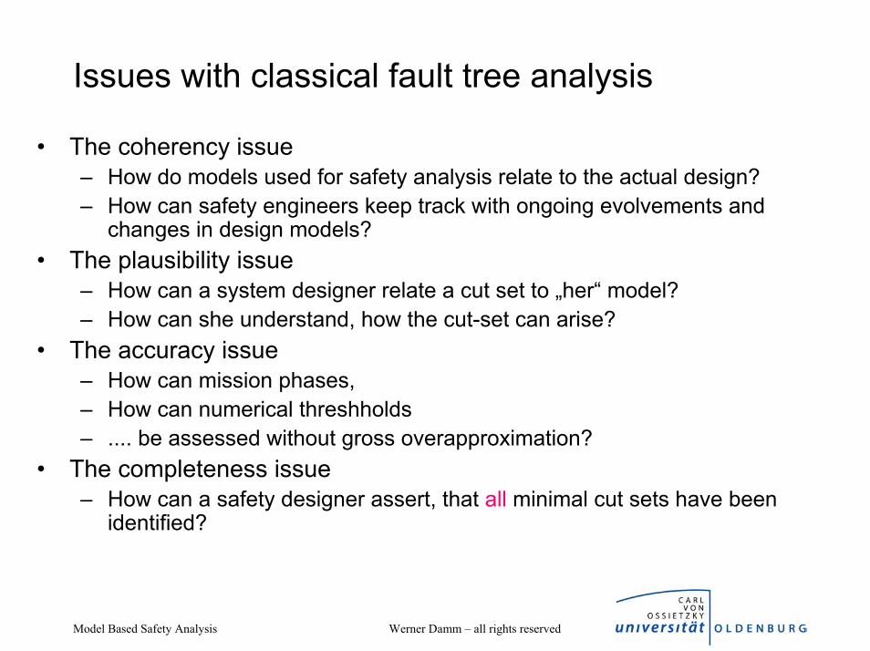
Issues with classical fault tree analysis
• The coherency issue– How do models used for safety analysis relate to the actual design?– How can safety engineers keep track with ongoing evolvements and
changes in design models?• The plausibility issue
– How can a system designer relate a cut set to „her“ model?– How can she understand, how the cut-set can arise?
• The accuracy issue– How can mission phases,– How can numerical threshholds– .... be assessed without gross overapproximation?
• The completeness issue– How can a safety designer assert, that all minimal cut sets have been
identified?

Model Based Safety Analysis Werner Damm – all rights reserved
Aircraft LevelRequirements
Allocation ofAircraft Functions
to Systems
Developmentof System
Architecture
Allocation ofRequirements to
Hardware &Software
SystemImplementation
Certification
System Development ProcessSafety Assessment Process
Aircraft
Functions
System
Functions
Failure Condition, Effects,Classification, Safety Objectives
Failure Condition, Effects,Classification, Safety
System
Architecture
Item Requirements
Aircraft LevelFHA
System LevelFHA Sections
PSSAs Architectural
Requirements
CCAs
Functional Interactions
FailureConditions& Effects
Separation
Requirement
SSAs
Implementation
Results
SeparationVerification
Item RequirementsSafety Objectives,
Analyses Required
Physical System
Objectives
The ESACS Approach towards ARP 4754 and 4761
• Model Based Approach– Conceptual models for early
Analysis– Model Based System
Development• Reduce Level of
misconception between System-Designers and Safety Engineers
Supported by GROWTHhttp: //www.esacs.org

Model Based Safety Analysis Werner Damm – all rights reserved
Embedding failures into System Models
• User specifies fault configuration– Associates with design units failure modes
• Fault configurations guide “patching” of semantic representation of Statemate model– Each failure is represented by
• Boolean input: failure occurs when set• Boolean local variable: set once failure has been observed• Failure model: automata based semantic representation of
effect of failure– Glue logic disconnects “nominal semantics” driving design
unit upon occurrence of failure input, switches to failure model
• Allows full propagation of failure effect on all design entities

Model Based Safety Analysis Werner Damm – all rights reserved
Model Checking Based Safety Analysis
• ModelChecking based FTA tool automatically performs fault-tree analysis on system model taking into account injected failure modes
• Computed fault-tree represents all minimal cut sets leading to given top-level event
• Cut sets can be analysed on extended system model using simulation: how can this cut set arise?
• Fault-trees can be exported to FTA+ for analysis of failure probabilities
Event 1
Event 2Event 4
Event 3
Event 4Event 2

Model Based Safety Analysis Werner Damm – all rights reserved
BDD based FT generation
TLE
initial states
1) ensure nominal correctness
If the design is(nominally) correct
this path does not exist
2) ⇒ there is no path to the top-level event (TLE)
3) Extend the model with failures triggered by additional inputs
4) Introduce additional local variables recordingthe occurence of failures (Failure Variables)
5) Check what valuations of failure variablesallow the TLE to be reached ...
However, failures introduce
additional paths

Model Based Safety Analysis Werner Damm – all rights reserved
BDD-Verfahren
(e,c=0), (e,c=1), (e,c=2), …(e,c=79), (e,c=80),(e,c=0)_
e
c6c6
e ∧ c≤80∨ e ∧ c=0
_
≅
c5c5
c4c4
c3
c2
c1
c0
0
0
0
0
0
0
0
01
- +BDD: Binary Decision Diagram= binärer Entscheidungsgraph.
Dient zur kompakten Darstellung von Mengen.

Model Based Safety Analysis Werner Damm – all rights reserved
BDD based FT generation
⇒ Checking for occurrence of failures can be deferred until TLE has been reached
It is guaranteed (by model extension) that failurevariables are never reset
TLE
initial states
Setting of failure variables
⇒ Can use classical reachability analysis to check whether failures lead to TLE

Model Based Safety Analysis Werner Damm – all rights reserved
Reachability based FT generation
• Compute BDD representing intersection of TLE with set of reachable states
• Project to local variables representing occurrence of failures
• Translate this BDD into disjunctive normal form
• By BDD reduction rules, all conjuncts are minimal cut sets
• Yields flat fault-tree• (ongoing extension: reflect
structure of model)
TLE
initial states

Model Based Safety Analysis Werner Damm – all rights reserved
simple SAT-based methods don´t work
⇒ incomplete (as long as model diameter is not reached)⇒ (for practical reasons) also incomplete with respect
to number of possible failure combinationsExample:
There are 1275 possibilities to have at most two(but at least one) failure activated among 50 possible failures.
initial states
TLE
Perform „drive-to“ analysisfor certain failure combinationswith BMC methods
Using extended model T‘:Init(s0) ∧ T‘(s0,fv1,s1) ∧ ... ∧ T‘(sn-1,fvn,sn) ∧ noloop(s0,...,sn) ∧ TLE(sn) ∧ fv = fv1 ∨ ... ∨ fvn

Model Based Safety Analysis Werner Damm – all rights reserved
Using Abstractiontraditional abstraction techniques are safe also when constructing fault trees (due to percistency of setting of local variables associated with failures)
TLE
fv1 fv5 fv3 fv4 fv2 fv5
Resulting fault tree will be too pessimistic:
If this is an abstract fault tree ...
fv4 fv3
... this might be the right one

Model Based Safety Analysis Werner Damm – all rights reserved
Concretizing abstract fault-treesTLE
fv1 fv5 fv3 fv4 fv2 fv5
Trying to concretizeabstract cut sets:
Abstract cut setnot reachable⇒ some failure variables are missing
? ?
Abstract cut set Creachable⇒ C is concrete cut set
initial states
perform BMC based „drive-to-cut-set“ (non-cut-set fv set to false)
Can use abstraction refinement:
for each (non concretizable) abstract cut set C perform FT computation for C ∧ TLE

Model Based Safety Analysis Werner Damm – all rights reserved
Example (cont.)
• TLE: The Flap System outputs RETRACT and EXTEND shall never be true at the same time.
• Injected FMs (random/persistent):– RETRACT_EV (EVENT 3)– EXTEND_EV (EVENT 4)– SHUTDOWN_EV– ALL_STOPPED_CN (EVENT 1)– INHIBIT_STARTUP_CN (EVENT
2)• Cut-sets show, that controller is not
protected against failures impacting inhibit-startup
– Nominal usage: hydraulic pressure too low
– Uncontrolled occurrences due to failures can cause contradicting actuator settings for flap system

Model Based Safety Analysis Werner Damm – all rights reserved
Acknowledgements
• Work performed under Growth projects ESACS and ISAAC– Airbus UK, D, F, Alenia, Saab– OFFIS team T. Peikenkamp, E. Böde, A. Lüdtke, H. Spenke
• Thanks to Matthias Brettschneider (Airbus DE) and Jean Pierre Heckmann (Airbus F) for many deep discussions
• Figures marked ©N.S. are courtesy to Neil Storey, taken from his book “Safety Critical Computer Systems”, Addison Wesley
Published in Proc. Incose 2004, Model-based Safety Analysis of a Flap Control System

Model Based Safety Analysis Werner Damm – all rights reserved
Conclusion
• Model Based Safety Analysis is seen as a key objective by avionics companies to further improve the (already high!) quality of the safety analysis process
• Feasibility demonstrated in ESACS, further enhancements and optimization as part of ISAAC project
• Ongoing cooperation with Airbus in Depnet project addresses compositional approaches to safety analysis


![Vorlesung Compiler für Eingebettete Systeme (SS14) · Compiler für Eingebettete Systeme [CS7506] Sommersemester 2014 Heiko Falk Institut für Eingebettete Systeme/Echtzeitsysteme](https://img.dokumen.tips/doc/110x75/5e0bcca2238c66363403635c/vorlesung-compiler-fr-eingebettete-systeme-ss14-compiler-fr-eingebettete-systeme.jpg)