Embed Size (px)
Citation preview

Model-based Design of Safety-Critical Aircraft SystemsModellbasierter Entwurf sicherheitskritischer Flugzeugsysteme
Dr.-Ing. Oliver Bertram
11 March 2021
ASIM STS/GMMS & EDU 2021
> Model-based Design of Safety-Critical Aircraft Systems > DLR Institute of Flight Systems > 11 March 2021 > Dr.-Ing. Oliver BertramDLR.de • Chart 1

The German Aerospace Center – DLRDeutsches Zentrum für Luft- und Raumfahrt e.V.
• DLR as large scale research facility:
• is the largest Science Center for Aerospace in Germany with the main research
areas: aviation, space, transport, energy and security
• is the German Space Agency. In this role DLR manages the German space program
on behalf of the government
• Is one of the largest Project Administration for publically founded projects in Germany
• DLR has about 9000 employees in 50 institutions at 27 locations
> Model-based Design of Safety-Critical Aircraft Systems > DLR Institute of Flight Systems > 11 March 2021 > Dr.-Ing. Oliver BertramDLR.de • Chart 2

Institute of Flight Systems
• Key data about the institute
• Founded in 1953 as Institute of Flight Mechanics
• Located in Braunschweig with a branch in Manching (cooperation with WTD 61)
• Director of the institute: Prof. Dr.-Ing. Stefan Levedag
• About 180 employees
• Six departments
• Rotorcraft
• Flight Dynamics and Simulation
• Unmanned Aircraft
• Flight Test Instrumentation & IT
• Flight Test (Manching)
• Safety Critical Systems & Systems Engineering
Braunschweig
Manching
> Model-based Design of Safety-Critical Aircraft Systems > DLR Institute of Flight Systems > 11 March 2021 > Dr.-Ing. Oliver BertramDLR.de • Chart 3

Departments of the Institute of Flight Systems
Unmanned Aircraft (ULF)
Focus on: Autonomy and flight test of
unmanned aircraft
Research areas:
• Trajectory generation and navigation in unknown areas
• Control of unmanned aircraft
• UAV risk assessment and airspace integration
Flight Dynamics and Simulation (FDS)
Focus on: Fixed wing aircraft and
simulation technology
Research areas:
• Flight dynamics and flight control
• Flight procedures
• Simulation technology
Helicopters (HUB)
Focus on: Rotorcraft
Research areas:
• Flight dynamics and rotor dynamics
• Flight control
• Pilot assistance
Flight Test Equipment and IT (FTV)
Focus on: Development of Flight Test
Equipment
Research areas:
• Electromagnetic compatibility
Flight Test (FEP)
New Department, hosted by WTD61 in
Manching
Safety Critical Systems and Systems
Engineering (SSY)
> Model-based Design of Safety-Critical Aircraft Systems > DLR Institute of Flight Systems > 11 March 2021 > Dr.-Ing. Oliver BertramDLR.de • Chart 4

Our Target Platforms Are:
> Model-based Design of Safety-Critical Aircraft Systems > DLR Institute of Flight Systems > 11 March 2021 > Dr.-Ing. Oliver BertramDLR.de • Chart 5

Main Objectives of the Department
• The main domain of the department are safety
critical aircraft systems. A special focus is set on
electrical and flight control systems
• Our research addresses new system designs to
realize beneficial functions, increase safety and
security and decrease development risk and life
cycle cost
• We create innovative design processes and
methods
• We utilize modern software tools for systems
engineering and in all relevant engineering
domains
> Model-based Design of Safety-Critical Aircraft Systems > DLR Institute of Flight Systems > 11 March 2021 > Dr.-Ing. Oliver BertramDLR.de • Chart 6

Department Main Research Areas
• The department addresses three core
research areas
• Design of safety critical aircraft systems
• Intelligent system functions, especially system
monitoring
• Embedded software engineering with special
focus on connectivity, safety and security
• Modern systems engineering methods as well
as safety and reliability are cross sectional
topics in the department
> Model-based Design of Safety-Critical Aircraft Systems > DLR Institute of Flight Systems > 11 March 2021 > Dr.-Ing. Oliver BertramDLR.de • Chart 7

➢We conduct applied research in the area of model-based systems engineering for complex systems• Methods for the design, analysis and evaluation of systems
• Development of interfaces to other disciplines and systems
• Development of seamless process and tool chains
➢We develop system concepts with maximum reconfigurability and robustness• Development of safety-critical system architectures
• Consideration of industrial usability and approval
• Analysis of interactions with aircraft design and other systems
➢We contribute to current trends and guiding concepts (DLR aeronautics)• Electric Flight, More/All Electric Aircraft, 1g Wing
• Intelligent and unmanned systems, autonomous flight, Urban Air Mobility
• Digitization, Virtual product
➢Our main applications: Flight control system, electric power supply, thermal management• The drivers are innovative technologies and new aircraft concepts
• Transferability from / to other areas of application is taken into account
Research of innovative technologies, concepts and methods
for complex, safety-critical systems
> Model-based Design of Safety-Critical Aircraft Systems > DLR Institute of Flight Systems > 11 March 2021 > Dr.-Ing. Oliver BertramDLR.de • Chart 8
Research group „Design of Safety-critical Systems“

➢CS 25.1309: Definition System
A combination of components, parts, and elements, which are inter-connected to perform one or more functions.
➢CS 25.1309: Definition Complex
A system is complex when its operation, failure modes, or failure effects are difficult to comprehend without the aid of
analytical methods.
➢ Intra-transparent behavior, non-linear effects and error propagation across system boundaries require strategies to
avoid design errors
➢CS 25.1309: Development Assurance
All those planned and systematic actions used to substantiate, to an adequate level of confidence, that errors in
requirements, design, and implementation have been identified and corrected such that the system satisfies the applicable
certification basis.
➢Application of Development Assurance Standards, e.g.:
• ARP4754A, ARP4761 (System Development and Safety Assessment)
• DO-178C (Software), DO-254 (Avionic Hardware), DO-297 (Integrated Modular Avionics)
• …
Definition: Complex System and Development Assurance
> Model-based Design of Safety-Critical Aircraft Systems > DLR Institute of Flight Systems > 11 March 2021 > Dr.-Ing. Oliver BertramDLR.de • Chart 9

Design Assurance System(Prevention, Detection, Elimination of Errors)
System Failures
(Development Errors)
Error in Design;
Requirements;
Implementation
Incident
Accident
Unsafe Condition
Safety is a Part of the System Development Process…especially for complex systems
> Model-based Design of Safety-Critical Aircraft Systems > DLR Institute of Flight Systems > 11 March 2021 > Dr.-Ing. Oliver BertramDLR.de • Chart 10
Courtesy:
Aviation Accident Database
AIR FRANCE flight AF358
Omission
or Incorrect Action by Flight Crew
or Maintenance Personnel
Loss of Function
or Malfunction
System Safety Assessment (Fail Safe Design, Assessment of Random Failures)
Non Systematic (Random) Failures
Infant Mortality
Random Failures
Wear Out
Courtesy: https://en.wikipedia.org/wiki/Bathtub_curve#/media/File:Bathtub_curve.svg

System Development Process for Safety-critical Systems(according to ARP4754A and ARP4761)
> Model-based Design of Safety-Critical Aircraft Systems > DLR Institute of Flight Systems > 11 March 2021 > Dr.-Ing. Oliver BertramDLR.de • Chart 11
System
Requirements
Identification
Aircraft
Requirements
Identification
Item
Requirements
Identification
Item DesignItem
Verification
System
Verification
Aircraft
Verification
Aircraft FHA
Prelimin. Aircraft
Safety Assessment
Aircraft Common
Cause Analysis
System FHA
Prelimin. System
Safety Assessment
System Common
Cause Analysis
System Fault-Tree
Analysis
System Common
Mode Analysis
SW&HW Design
System Fault-Tree
Analysis
System Common
Mode Analysis
System
FMEA/FMES
System Safety
Assessment
System Common
Cause Analysis
Aircraft Safety
Assessment
Aircraft Common
Cause Analysis
System
FMEA/FMES
Requirements
Validation
Requirements
Validation
Requirements
Validation
Aircraft Verification
System Verification
Item Verification
FDAL & IDAL Processes

Typical Certification ProcessCommission Regulation (EU) No 748/2012 Annex I Part 21 Subpart B: Type Certification
> Model-based Design of Safety-Critical Aircraft Systems > DLR Institute of Flight Systems > 11 March 2021 > Dr.-Ing. Oliver BertramDLR.de • Chart 12
CS – Certification SpecificationCRI – Certification Review Item
Certification
Programme
Acceptable
Means of
Compliance
CS-2x,…
Customer
Requirements
Type Design
Safety Assessments
ARP 4761
Certification
Basis
CS-2x; CS-E;
CS-P; CS-34;
CS-ETSO
CRI-T XX
Special
Conditions
Development Life Cycle
ARP4754A; DO-178C; DO-254
Project
Requirements
Type
Certificate
Certification Documents
Definition [ICAO Annex 8]
„Airworthy“:
„The status of an aircraft,
engine, propeller or part
when it conforms to its
approved type design
and is in a
condition for safe operation.“

Systems Engineering – Managing ComplexityDefinition and Tasks
➢ INCOSE Definition: Systems Engineering (SE)
Systems Engineering is a transdisciplinary and integrative
approach to enable the successful realization, use, and
retirement of engineered systems, using systems principles
and concepts, and scientific, technological, and
management methods.
• It focuses on defining customer needs and required
functionality early in the development cycle, documenting
requirements, and then proceeding with design synthesis.
• SE and system validation while considering the complete
problem: operations, cost and schedule, performance,
training and support, test, manufacturing, and disposal.
• SE considers both the business and the technical needs of
all customers with the goal of providing a quality product
that meets the user needs.
> Model-based Design of Safety-Critical Aircraft Systems > DLR Institute of Flight Systems > 11 March 2021 > Dr.-Ing. Oliver BertramDLR.de • Chart 13
SE Tasks
Planningand
Reporting
Require-ments
System Documen-
tation
System Design Optimi-zation
System Integration
System Verification
andValidation
Configu-ration andChange Manage-
ment
RiskManage-
ment
Product andQuality
Assurance
International Council on
Systems Engineering

Model-based Systems Engineering
➢ INCOSE Definition: Model-based Systems Engineering (MBSE)
The formalized application of modeling to support system requirements,
design, analysis, verification and validation activities beginning in the
conceptual design phase and continuing throughout development and
later life cycle phases.
• Systems Modeling Language (OMG SysML) is a graphical,
standardized modeling language based on UML 2
• Benefits
• Strict and unambiguous views without misunderstandings
• Stronger common system understanding
• Supports automatic plausibility tests and code generation
• Increase system specification accuracy
• Traceability between development steps
• Supports reusability
> Model-based Design of Safety-Critical Aircraft Systems > DLR Institute of Flight Systems > 11 March 2021 > Dr.-Ing. Oliver BertramDLR.de • Chart 14
Model
View 1
View 2
Same model – Different views
Single source of truth
Model-based Systems Engineering – 4 Pillars of SysML
> Model-based Design of Safety-Critical Aircraft Systems > DLR Institute of Flight Systems > 11 March 2021 > Dr.-Ing. Oliver BertramDLR.de • Chart 15
1. Structure 2. Behaviour
4. Parametrics3. Requirements

Domain Engineering (Analysis Models)Systems Engineering (System Model)
Bridging the Gap between MBSE and Engineering Domains
> Model-based Design of Safety-Critical Aircraft Systems > DLR Institute of Flight Systems > 11 March 2021 > Dr.-Ing. Oliver BertramDLR.de • Chart 16
1. Structure 2. Behaviour
4. Parametrics3. Requirements
Mechanical
• Multidisciplinary Analysis
• Optimization
• Design Space Exploration
• Analysis requests and specifications
• Requirements
• Performance Estimates
• Requirements Conformance
• Study Results
Electrical Simulation/Test …
System Documentation
and Specifications

Tools / Tool Environments
> Model-based Design of Safety-Critical Aircraft Systems > DLR Institute of Flight Systems > 11 March 2021 > Dr.-Ing. Oliver BertramDLR.de • Chart 17
Cameo Systems Modeler / SysML; Safety Plugins, Requirements
DLR: RCE, CPACS
ASySi & Miscellaneous / Python
SysArc / C#
Dymola / Modelica; Matlab/Simulink/Simscape
CATIA , Adams, Ansys
System Modeling
Safety, Reliability
Workflow-Driven
Multidisciplinary
Design & Simulation
Design
Detailed Design
(Co-)Simulation
(Co-)Simulation
MB
SE
Do
main
En
gin
eeri
ng
To
ols
FTA

Example High-lift SystemFunctions and Devices
High-lift System Function
• Increase in amount of lift produced by the wing (in take-off and landing)
• Increase in drag (in landing),
• Aircraft can fly already at lower speeds with higher angle of attack
→ Decrease in required runway length
• By extending leading and trailing edge devices
High-Lift Devices (A330 Example)
• Slats → 7 per main wing
• Flaps → 2 per main wing
• Inboard flap → 2 support stations
• Outboard flap → 3 support stations
• Flap extension/retraction → „Fowler“ motion → Realized by mechanisms
• Each flap mechanism → Driven by geared rotary actuator (GRA)
> Model-based Design of Safety-Critical Aircraft Systems > DLR Institute of Flight Systems > 11 March 2021 > Dr.-Ing. Oliver BertramDLR.de • Chart 18
Cruise
Take-off
Landing
Inboard flap
Outboard flap
Slats
Flap supports

Flap Actuation System Architecture
> Model-based Design of Safety-Critical Aircraft Systems > DLR Institute of Flight Systems > 11 March 2021 > Dr.-Ing. Oliver BertramDLR.de • Chart 19
SFCC 1 SFCC 2
Flap
lever
Valve
Diff.
gear
boxM POB
Valve
MPOB
Green
supply
Yellow
supply
FPPURight wing
DDG
GRA
APPU
Outboard flap
DDG
GRA
DDG
GRA
DDG
GRA
DDG
GRA
Inboard flap
WTB
SFCC 2
SFCC 1
SFCC 1
SFCC 2
Wing tip brake
Power control unit
Feedback
position
pick-off unit
Asymmetry position
pick-off unitGeared rotary actuator
Shaft and bearings
Power off brake
DDG: Down drive gearbox
SFCC: Slat flap control
computer
M: Hydraulic motor

System Monitoring
• Must ensure the correct flap positioning within the operating limits (incl. overload protection)
• Must handle with safety-critical failures
• Should maintain the overall functionality in case of failures or component malfunctions
> Model-based Design of Safety-Critical Aircraft Systems > DLR Institute of Flight Systems > 11 March 2021 > Dr.-Ing. Oliver BertramDLR.de • Chart 20
Shaft Rupture
Failure case example
Shaft rupture → Separation of drivetrain → Asymmetry → Aircraft roll moment → Catastrophic effect
Failure detection concept
Measurement of angular positions (FPPU/APPU) → Angular difference over the threshold → SFCCs activate brakes (WTB,
POB) → System stopped → Catastrophic effect avoided

Modeling and Simulation of High-lift Systems
• Goal is to predict the real system behavior through computer
simulations
• Operating conditions
• Normal operation (Flaps positioning against loads,
positioning time)
• Malfunctions (Jamming, failure of the power supply)
• Safety-critical failures (Asymmetry, run-away)
• Environmental conditions (Low or high temperature)
• Assessment
• System performance in stationary conditions (e.g. positioning at low
temperature)
• System dynamics for component design and system monitoring
• Characteristic times and system speeds
• Dynamic loads through transient changes in operating
conditions (e.g. through activating brakes)
> Model-based Design of Safety-Critical Aircraft Systems > DLR Institute of Flight Systems > 11 March 2021 > Dr.-Ing. Oliver BertramDLR.de • Chart 21

Shaft Rupture Simulation Example
• Drive train simulation model
• Nonlinear torsional oscillating system
• Locally lumped parameters
• Extended by frictional losses, mechanical
backlash, efficiency and other effects
• Physics-based component catalog
• Simulation
• Normal operation
• Shaft rupture @4s
> Model-based Design of Safety-Critical Aircraft Systems > DLR Institute of Flight Systems > 11 March 2021 > Dr.-Ing. Oliver BertramDLR.de • Chart 22
Down drive gear
box (DDG)
Shaft
Geared rotary
actuator (GRA)
Wing tip
brake (WTB)
Control and
monitoring
Power control
unit (PCU)
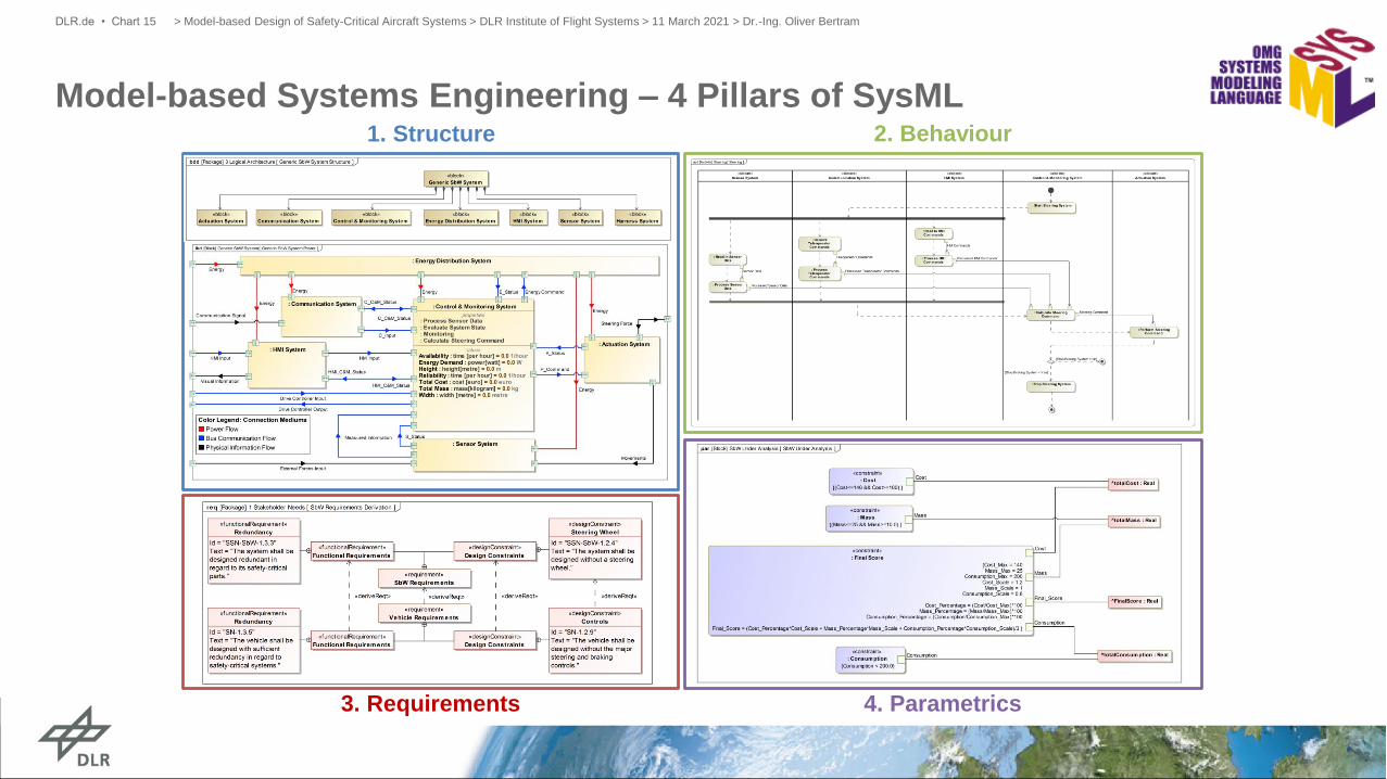
Model-based Design Validation and VerificationProcess Implementation as RCE workflow (Systems)
> Model-based Design of Safety-Critical Aircraft Systems > DLR Institute of Flight Systems > 11 March 2021 > Dr.-Ing. Oliver BertramDLR.de • Chart 23
Mo
va
ble
Me
ch
an
ism
1
Me
ch
an
ism
2
Actu
ato
r 1
Actu
ato
r 2
Movable
Mechanism 1 1
Mechanism 2 1
Actuator 1 1
Actuator 2 1

Model-based Design Validation and VerificationModeling of Requirements and Test Cases
• Model requirements and numerical constraints
• Test case and simulation configuration
• Map to failure modes and requirements
• Configure simulation script
• Feedback requirement related simulation results to
systems model
> Model-based Design of Safety-Critical Aircraft Systems > DLR Institute of Flight Systems > 11 March 2021 > Dr.-Ing. Oliver BertramDLR.de • Chart 24

Model-based Design Validation and VerificationDesign Change Example
• Shaft disconnect test
(3 vs. 2 outboard flap tracks)
• Flap deployment
• Failure injection @4s at shaft inboard
to WTB
• Asymmetry detection threshold @4°
> Model-based Design of Safety-Critical Aircraft Systems > DLR Institute of Flight Systems > 11 March 2021 > Dr.-Ing. Oliver BertramDLR.de • Chart 25
load load load
load load
3 outboard
flap tracks
2 outboard
flap tracks feed test results in system model
𝜑𝑑𝑒𝑡𝑒𝑐𝑡
detection
time
evaluate
constraints

Virtual Certification - Challenges
• Model-based (=virtual) design validation supports the
design process, since system behavior can be
estimated using simulation models early in the design
process and before the first prototypes are built
• In order to be able to use model-based design (virtual
methods) for product certification, the models and
methods used must be accepted
> Model-based Design of Safety-Critical Aircraft Systems > DLR Institute of Flight Systems > 11 March 2021 > Dr.-Ing. Oliver BertramDLR.de • Chart 26
Virtual Certification
Verification
Experience
Docu-mentation
Extra-polation
Validation
Errors & Uncertain-
ties
• How can these be done without complex test rigs?

Questions?
> Model-based Design of Safety-Critical Aircraft Systems > DLR Institute of Flight Systems > 11 March 2021 > Dr.-Ing. Oliver BertramDLR.de • Chart 27
[flaticon.com]Dr.-Ing. Oliver Bertram
Telephone +49 (0) 531 295-3575
www.DLR.de/ft