Embed Size (px)
Citation preview
1© 2016 The MathWorks, Inc.
Model-Based Design:
Design with Simulation in Simulink
Ruth-Anne Marchant
Application Engineer
MathWorks

2

3
Outline
Model-Based Design Overview
Modelling and Design in Simulink
– Modelling Physical Systems
Control logic
– Simulation System-level optimisation
Verification of design changes
Summary

4
Electrical
Components
EDA
Mechanical
Components
MCAD/
MCAE
Embeddable
Algorithms
Algorithm
Design
Traditional Development Workflow
SPECIFICATIONS
DESIGN AND IMPLEMENTATION
RESEARCH REQUIREMENTS
Embedded
Software
C/C++
INTEGRATION AND TEST
Electrical
Components
EDA
Mechanical
Components
MCAD/
MCAE
Embeddable
Algorithms
Algorithm
Design
DESIGN AND IMPLEMENTATION
Embedded
Software
C/C++
5
Electrical
Components
EDA
Mechanical
Components
MCAD/
MCAE
Embeddable
Algorithms
Algorithm
Design
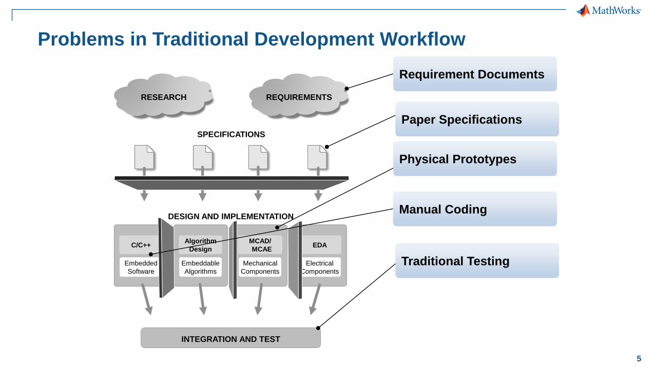
Problems in Traditional Development Workflow
SPECIFICATIONS
DESIGN AND IMPLEMENTATION
RESEARCH REQUIREMENTS
Embedded
Software
C/C++
Paper Specifications
Physical Prototypes
Manual Coding
Requirement Documents
INTEGRATION AND TEST
Traditional Testing
6
INTEGRATION
IMPLEMENTATION
DESIGN
Environment Models
Physical Components
Algorithms
Structured
TextVHDL, VerilogC, C++
TE
ST
& V
ER
IFIC
AT
ION
RESEARCH REQUIREMENTS
PLC, PACMCU DSP FPGA ASIC
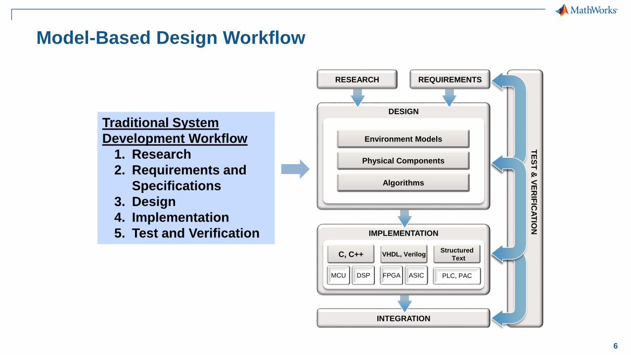
Model-Based Design Workflow
Traditional System
Development Workflow
1. Research
2. Requirements and
Specifications
3. Design
4. Implementation
5. Test and Verification
7
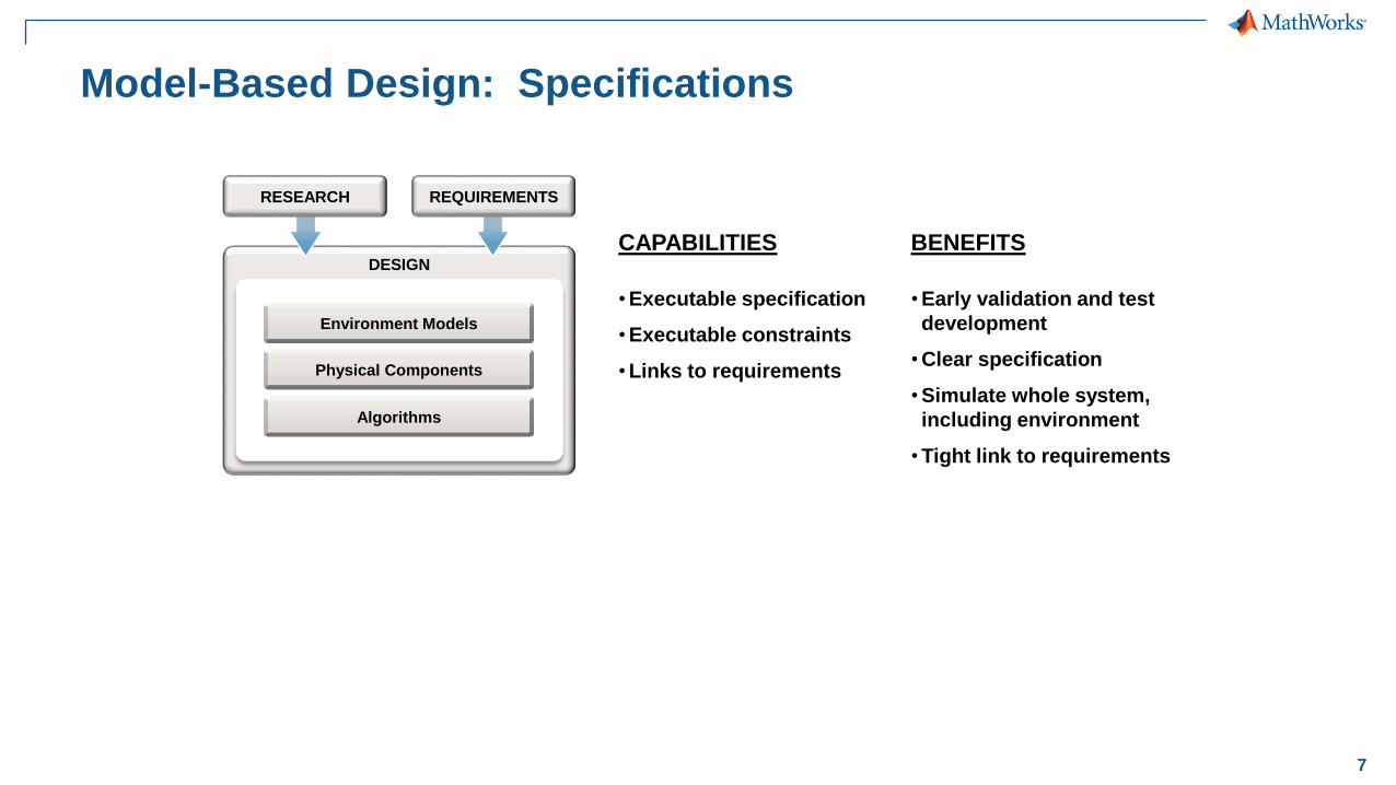
Model-Based Design: Specifications
CAPABILITIES
•Executable specification
•Executable constraints
•Links to requirements
BENEFITS
•Early validation and test
development
•Clear specification
•Simulate whole system,
including environment
•Tight link to requirements
DESIGN
Environment Models
Physical Components
Algorithms
RESEARCH REQUIREMENTS

8
Model-Based Design: Requirements
Trace to requirements in DOORS, Word, Excel, etc.Model system response bounds
Formalize requirements as properties and objectives
DESIGN
Environment Models
Physical Components
Algorithms
RESEARCH REQUIREMENTS

9
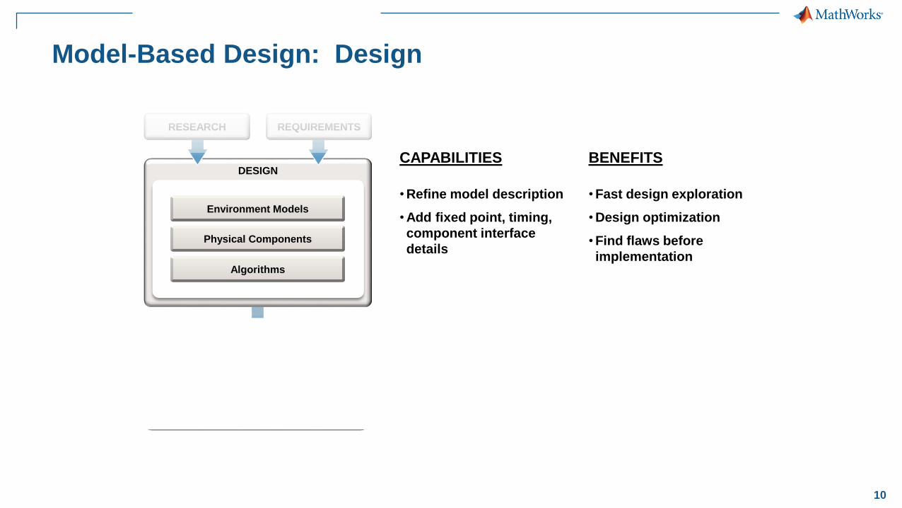
CAPABILITIES
•Refine model description
•Add fixed point, timing,
component interface
details
DESIGN
Environment Models
Physical Components
Algorithms
RESEARCH REQUIREMENTS
BENEFITS
•Fast design exploration
•Design optimization
•Find flaws before
implementation
Model-Based Design: Design
10
CAPABILITIES
•Refine model description
•Add fixed point, timing,
component interface
details
Physical Components
Algorithms
IMPLEMENTATION
Structured
TextVHDL, VerilogC, C++
PLC, PACMCU DSP FPGA ASIC
DESIGN
Environment Models
Physical Components
Algorithms
RESEARCH REQUIREMENTS
BENEFITS
•Fast design exploration
•Design optimization
•Find flaws before
implementation
Model-Based Design: Design
11
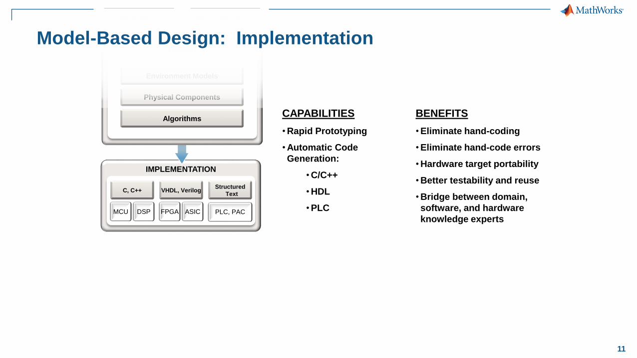
CAPABILITIES
•Rapid Prototyping
•Automatic Code
Generation:
•C/C++
•HDL
•PLC
BENEFITS
•Eliminate hand-coding
•Eliminate hand-code errors
•Hardware target portability
•Better testability and reuse
•Bridge between domain,
software, and hardware
knowledge experts
IMPLEMENTATION
DESIGN
Environment Models
Physical Components
Algorithms
RESEARCH REQUIREMENTS
Structured
TextVHDL, VerilogC, C++
PLC, PACMCU DSP FPGA ASIC
Model-Based Design: Implementation
12
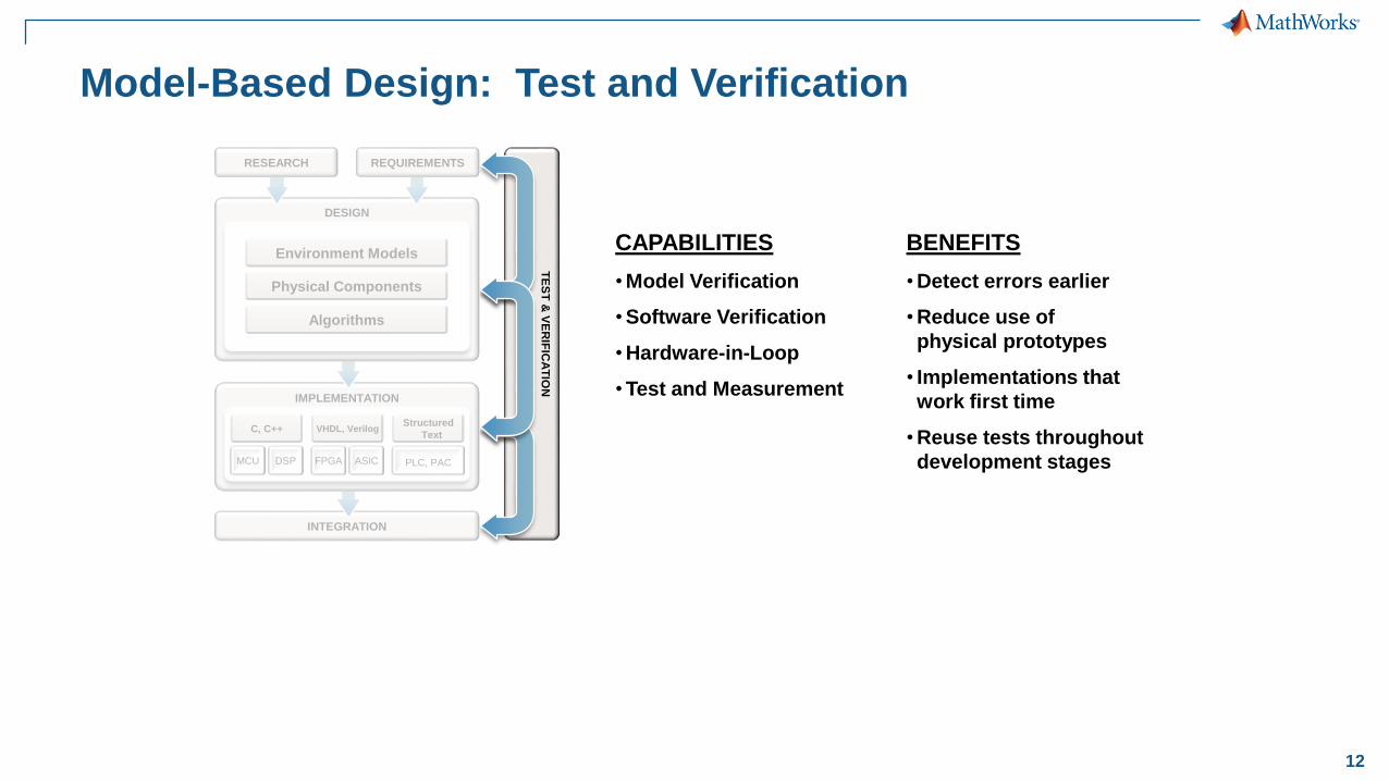
CAPABILITIES
•Model Verification
•Software Verification
•Hardware-in-Loop
•Test and Measurement
BENEFITS
•Detect errors earlier
•Reduce use of
physical prototypes
• Implementations that
work first time
•Reuse tests throughout
development stages
TE
ST
& V
ER
IFIC
AT
ION
INTEGRATION
IMPLEMENTATION
DESIGN
Environment Models
Physical Components
Algorithms
Structured
TextVHDL, VerilogC, C++
RESEARCH REQUIREMENTS
PLC, PACMCU DSP FPGA ASIC
Model-Based Design: Test and Verification
13
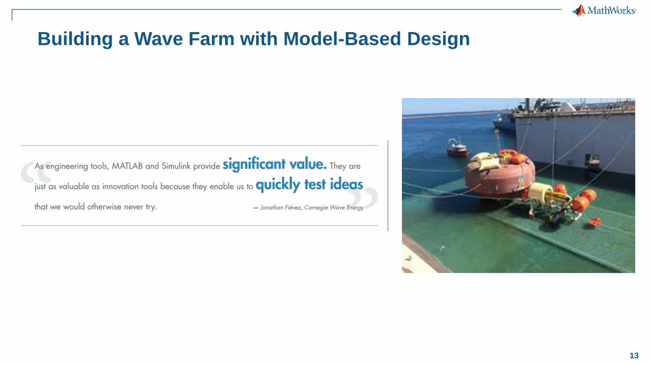
Building a Wave Farm with Model-Based Design
14
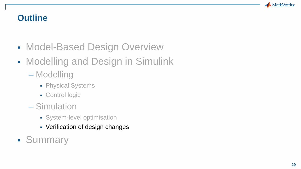
Outline
Model-Based Design Overview
Modelling and Design in Simulink
– Modelling Physical Systems
Control logic
– Simulation System-level optimisation
Verification of design changes
Summary

15
Outline
Model-Based Design Overview
Modelling and Design in Simulink
– Modelling Physical Systems
Control logic
– Simulation System-level optimisation
Verification of design changes
Summary

16
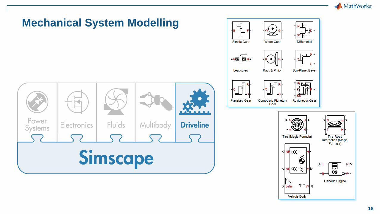
Mechanical System Modelling

17
Mechanical System Modelling
18
Mechanical System Modelling
19
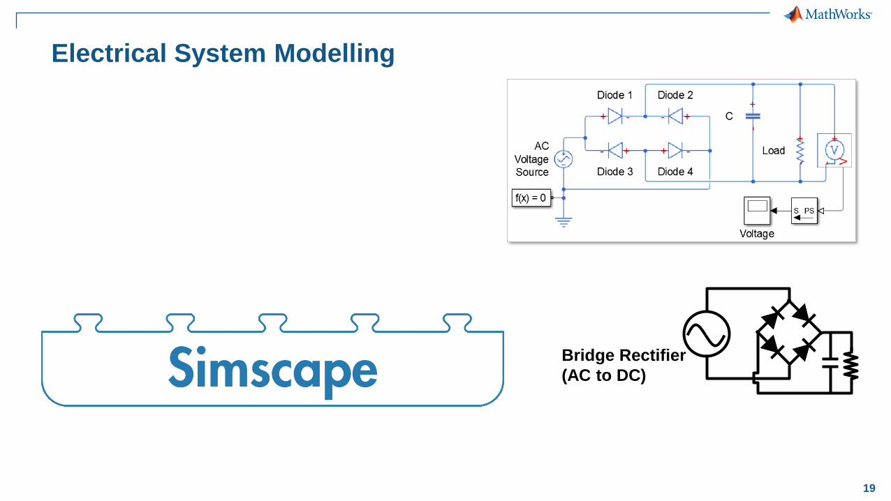
Electrical System Modelling
Bridge Rectifier
(AC to DC)

20
Electrical System Modelling
Speed Controller
DC Motor
Motor
Servoamplifier
Hall Effect
Sensor

21
Electrical System Modelling
22
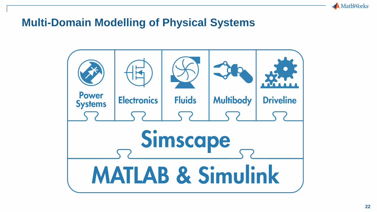
Multi-Domain Modelling of Physical Systems
23
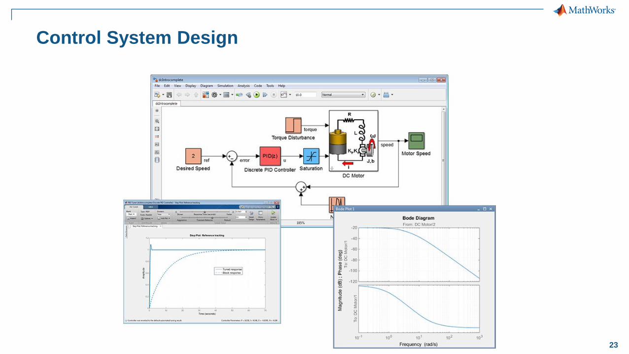
Control System Design
24
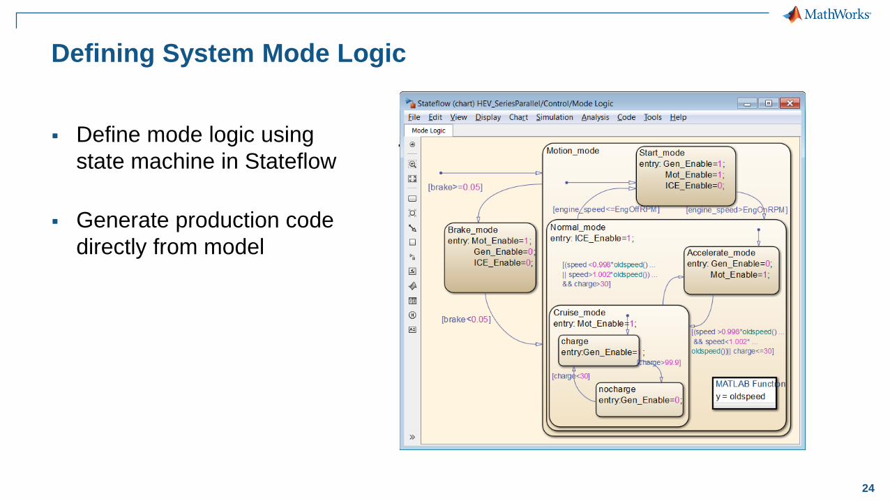
Defining System Mode Logic
Define mode logic using
state machine in Stateflow
Generate production code
directly from model
Motion
Normal Mode
Cruise Mode
Charge
No
Charge
Acceleration
Mode
Start Mode
RPM
> 800RPM
< 790
Accel is low
&&
Charge is low
Accel is high &&
Charge is high
Charge
is high
Charge
is low
Brakes
applied
Brakes
released
Gen = 1
Engine = 0
Motor = 1
Gen = 0
Motor = 1
Mot = 1
Gen = 0
Engine = 0
Specification
Brake ModeEngine = 1

25
Outline
Model-Based Design Overview
Modelling and Design in Simulink
– Modelling Physical Systems
Control logic
– Simulation System-level optimisation
Verification of design changes
Summary

26
Optimise Entire System
Use optimisation algorithms to
automatically tune parameter values
– Match response
– Meet requirements
Optimise system performance
(controller and physical system)
HEV
Model
IC Engine On Spd
IC Engine Off SpdBattery Capacity
Battery Max Discharge Power
Fuel Consumed Over
100 Different Drive Cycles
Calculate
Cost
Optimisation
AlgorithmParameter Values
Motor Torque
Motor Speed

27
Distributing Simulations
with Parallel Computing
Simulating in parallel
– Distribute simulations to
multiple cores/processors
– Dramatic speedup for sets
of simulations (parameter
sweeps, flight cycles
optimisations, and more)
for parfor
…
Computer Cluster
Workers
… …
Desktop System
Workers
… …
Simulation 1
Simulation 2
HEV Model

28
Shorten Simulation Times With Parallel Computing
Problem: Minimize simulation time to run
a parameter sweep on the HEV model
Solution: Use Parallel Computing Toolbox
to speed up the sweep
Model:
Parameter Set 1
Parameter Set 2
Parameter Set N
…
Drive Cycles
Weights
Ratios
…
HEV Model
Multi
Core
29
Outline
Model-Based Design Overview
Modelling and Design in Simulink
– Modelling Physical Systems
Control logic
– Simulation System-level optimisation
Verification of design changes
Summary

30
Automatically Run Tests And Document Results
Problem: Evaluate test results
quickly to make design changes
and document the results
Solution: Use Simulink Report
Generator to automatically
document tests and results
Situation:
Design
Change
Test
Evaluate
Results
Document
Report
31
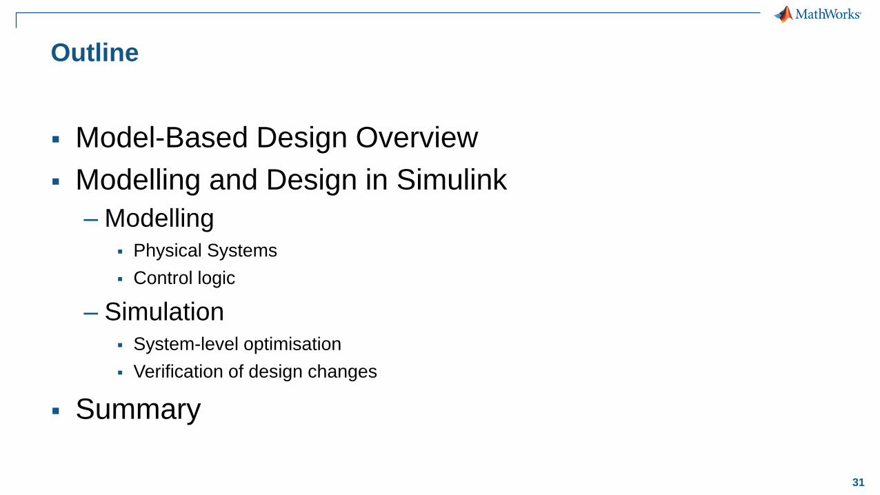
Outline
Model-Based Design Overview
Modelling and Design in Simulink
– Modelling Physical Systems
Control logic
– Simulation System-level optimisation
Verification of design changes
Summary

32
Key Points
Simulink is a multi-domain modelling and simulation environment
facilitating Model-Based Design
Optimise the system-level performance
Accelerate your development– Speed up simulations using Parallel Computing Toolbox
– Speed-up processes using Simulink Report Generator
33
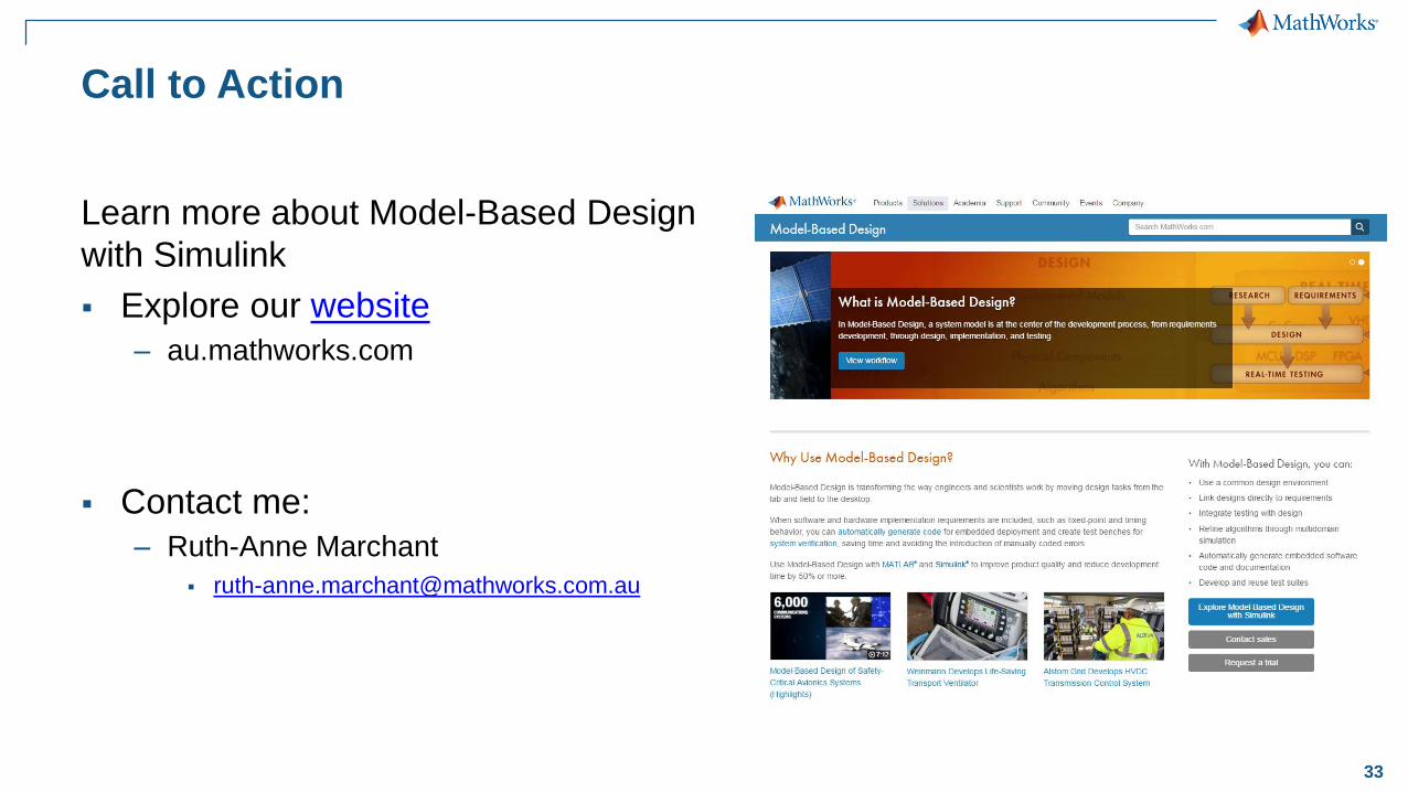
Call to Action
Learn more about Model-Based Design
with Simulink
Explore our website
– au.mathworks.com
Contact me:
– Ruth-Anne Marchant

34
Q & A