Embed Size (px)
Citation preview

Presented to:
Presented by:
Model Based Definition in NAVAIR
PLM Road Map™ 2015 for the
Aerospace & Defense
29– OCT – 2015
John Schmelzle NAVAIR 4.8.6 Additive Manufacturing and Model
Based Definition Initiative Lead

Agenda
2
1) How we got to where we are.
2) Where we are
3) Where are we going

The Rationale for 3D MBD
Current design process:
3D Model 2D
Drawing
3D Part 2D QA
Process
3D Product
3D Drawing design process:
3D Model/Drawing
3D Part
3D QA process
3D Product
Re-creation
Re-creation
3

PDDS vs. MBD in Engineering
4
PDDS: • Fully Annotated Model:
• Similar to conventional 2D drawing • Fully dimensioned • Part defined by dimensions on the
model • 2D Drawing with an Associated Model:
• Similar to the fully annotated model • Has 2D drawing with associated model
MBD: • Model itself defines the nominal condition of
the part • Traditional dimensions can be shown • Model is toleranced geometrically • Accuracy of model becomes critical
• Need for Verification
The Fully Annotated Model

MBD Example
5
Traditional Dimensioning Model Based Definition

3D PDF Platform
• Neutral File Format
• In Accordance with ASME Y14.41 – Need to Publish/Approve
• Readily Readable Format
• Compatible with JEDMICS
• Long Term Archiving and CAM compatibility – Embedded STEP
6
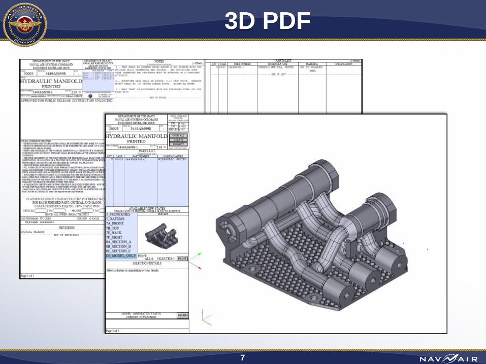
3D PDF
7

Producibility in MBD
8
Overhanging Fillet
The indicated fillet extends out to form
a sharp edge (see inset image).
Undercut Feature
The highlighted fillet cuts under the
upper part of this feature.

Verification in MBD
9
Wireframe curves indicating
fastener locations were not
exported into STEP file.
Creo File STEP File
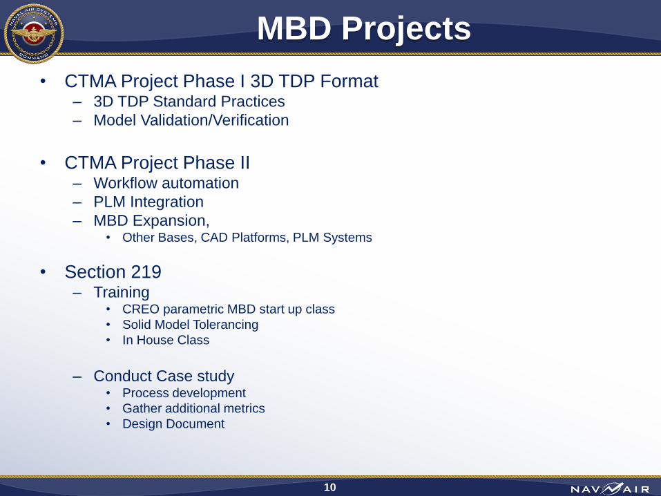
MBD Projects
• CTMA Project Phase I 3D TDP Format – 3D TDP Standard Practices
– Model Validation/Verification
• CTMA Project Phase II – Workflow automation
– PLM Integration
– MBD Expansion, • Other Bases, CAD Platforms, PLM Systems
• Section 219 – Training
• CREO parametric MBD start up class
• Solid Model Tolerancing
• In House Class
– Conduct Case study • Process development
• Gather additional metrics
• Design Document
10

Model Based Definition
Where are we?
NAVAIR Lakehurst
File: NAVAIR Brief 11
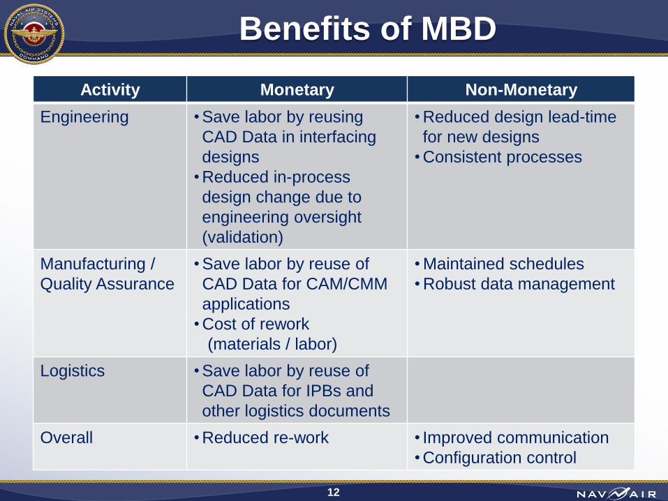
Benefits of MBD
Activity Monetary Non-Monetary
Engineering • Save labor by reusing
CAD Data in interfacing
designs
• Reduced in-process
design change due to
engineering oversight
(validation)
• Reduced design lead-time
for new designs
• Consistent processes
Manufacturing /
Quality Assurance
• Save labor by reuse of
CAD Data for CAM/CMM
applications
• Cost of rework
(materials / labor)
• Maintained schedules
• Robust data management
Logistics • Save labor by reuse of
CAD Data for IPBs and
other logistics documents
Overall • Reduced re-work • Improved communication
• Configuration control
12
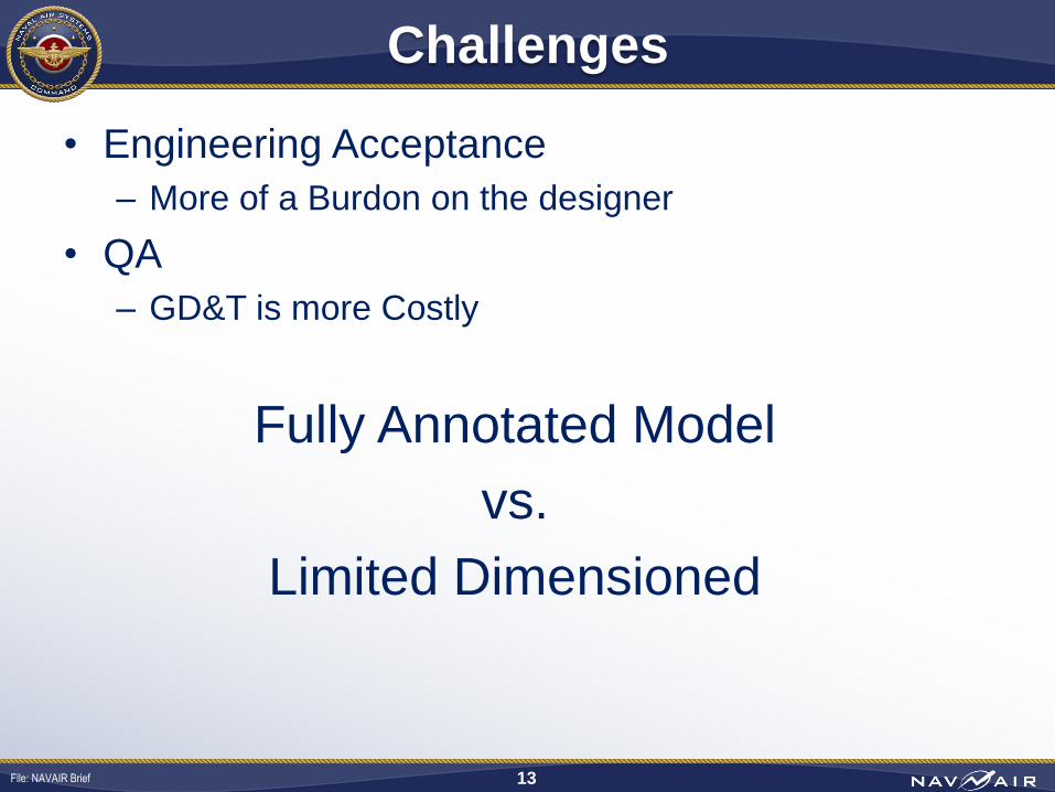
Challenges
• Engineering Acceptance
– More of a Burdon on the designer
• QA
– GD&T is more Costly
Fully Annotated Model
vs.
Limited Dimensioned
File: NAVAIR Brief 13

Model Based Definition
Where are we going?
NAVAIR Lakehurst
File: NAVAIR Brief 14

NAVAIR TDP
File: NAVAIR Brief 15
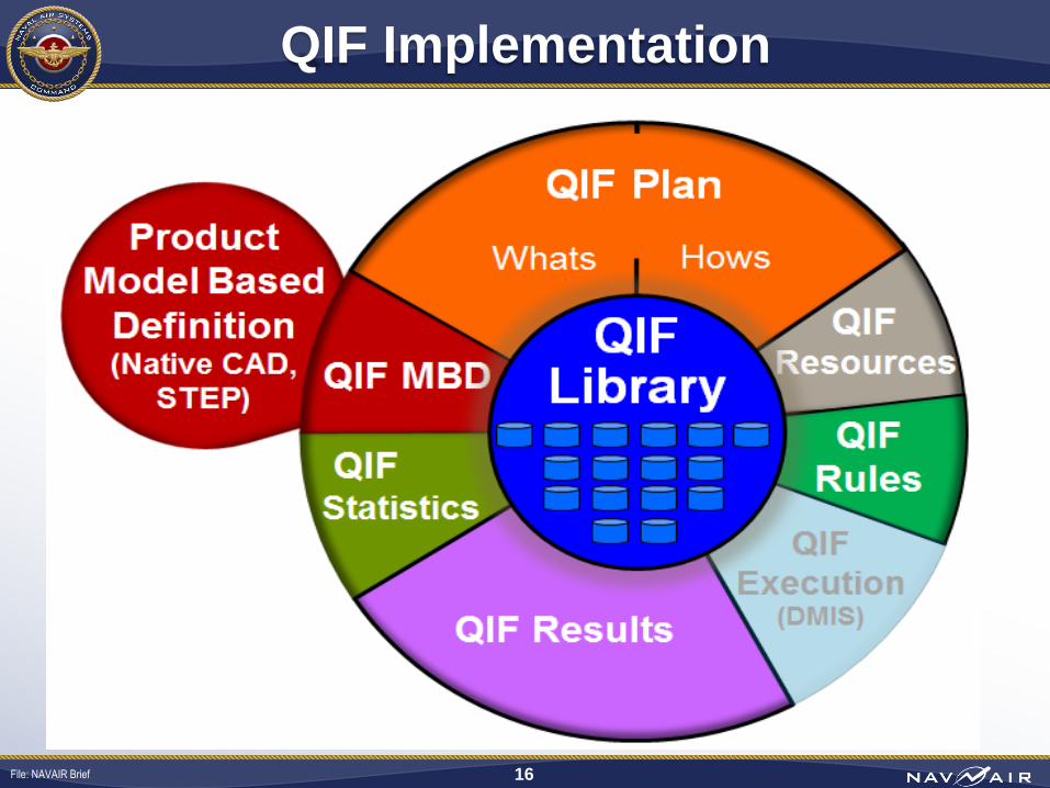
QIF Implementation
File: NAVAIR Brief 16
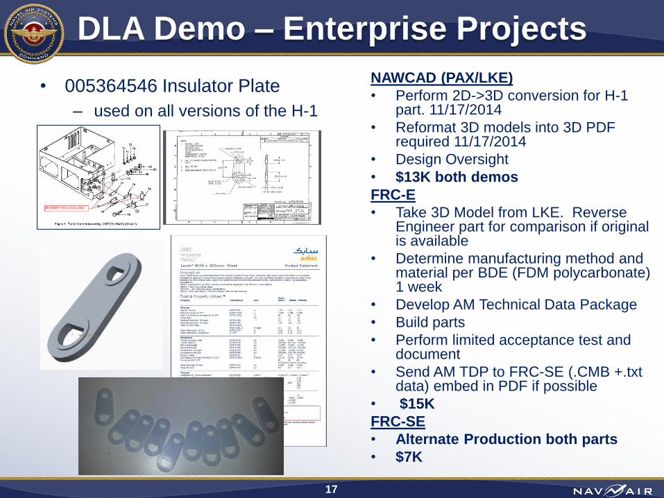
• 005364546 Insulator Plate
– used on all versions of the H-1
DLA Demo – Enterprise Projects
17
NAWCAD (PAX/LKE)
• Perform 2D->3D conversion for H-1 part. 11/17/2014
• Reformat 3D models into 3D PDF required 11/17/2014
• Design Oversight
• $13K both demos
FRC-E
• Take 3D Model from LKE. Reverse Engineer part for comparison if original is available
• Determine manufacturing method and material per BDE (FDM polycarbonate) 1 week
• Develop AM Technical Data Package
• Build parts
• Perform limited acceptance test and document
• Send AM TDP to FRC-SE (.CMB +.txt data) embed in PDF if possible
• $15K
FRC-SE
• Alternate Production both parts
• $7K
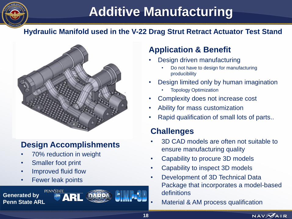
Additive Manufacturing
Application & Benefit
• Design driven manufacturing • Do not have to design for manufacturing
producibility
• Design limited only by human imagination • Topology Optimization
• Complexity does not increase cost
• Ability for mass customization
• Rapid qualification of small lots of parts..
18
Challenges
• 3D CAD models are often not suitable to
ensure manufacturing quality
• Capability to procure 3D models
• Capability to inspect 3D models
• Development of 3D Technical Data
Package that incorporates a model-based
definitions
• Material & AM process qualification
Design Accomplishments • 70% reduction in weight
• Smaller foot print
• Improved fluid flow
• Fewer leak points
Hydraulic Manifold used in the V-22 Drag Strut Retract Actuator Test Stand
Generated by
Penn State ARL
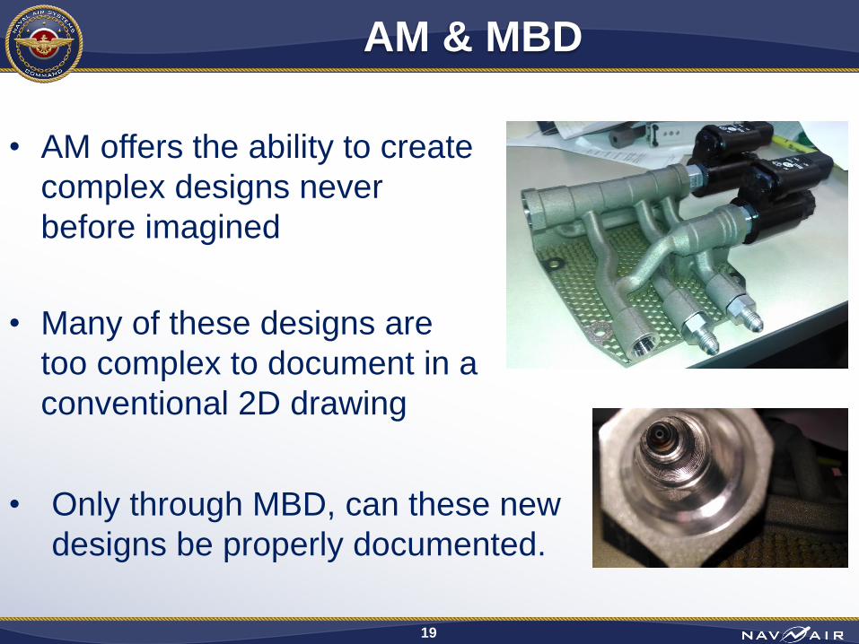
AM & MBD
• AM offers the ability to create
complex designs never
before imagined
• Many of these designs are
too complex to document in a
conventional 2D drawing
19
• Only through MBD, can these new
designs be properly documented.

Tank Return
PRDL
FPCH
FMDB
20
AM & MBD

Inspection Methods
Computed Tomography (CT)
• Provides an “inside look” into the
resultant part
• Form / Dimensionality (metrology)
• Porosity
• One of the only non-destructive
methods available for inspection
of internal features
21

Shipboard Additive Manufacturing
22
In the future, an Additive Manufacturing device will be installed aboard a ship and will create production parts • This equipment will support Naval Aviation
• It will need to be managed like other equipment supporting the fleet (Aircraft Servicing equipment / Maintenance equipment)
– It will need to be controlled
– It will need to be supported
– It will require training
Integrated Interoperable Additive Manufacturing (I2AM)
•Proposed Project to demonstrate the capability to
design, fabricate, test, and deploy polymeric
•AM parts / tools across Navy sites / pier-side/ship-
board. Support equipment (wire repair tools,
harnesses, and connectors) to be used to
demonstrated this capability.


![[NAVAIR 00-80T-114]](https://img.dokumen.tips/doc/110x75/577d26651a28ab4e1ea1163e/navair-00-80t-114.jpg)


