Embed Size (px)
Citation preview

UNIVERSAL DISPLAY PRODUCT LINE AL510 USERS GUIDE
INSTRUCTION MANUAL
For
MODEL AL510
UNIVERSAL INDICATOR DISPLAY
www.apogeelabs.com 210 South Third Street, North Wales, PA 19454
Ph. 215-699-2060

UNIVERSAL DISPLAY PRODUCT LINE AL510 USERS GUIDE
www.apogeelabs.com i
06.01.09 210 South Third Street, North Wales, PA 19454
Ph. 215-699-2060
WARRANTY
EXTENDED WARRANTY
Thank you for purchasing this equipment from APOGEE LABS, Inc. Our intention is that the
equipment meets your requirements and exceeds your expectations and you find our documen-
tation adequately describes its operation and use. We continue to strive for higher levels of
quality in our products, services and customer support and look forward to hearing from you if
you have any comments or questions regarding these areas. We sincerely believe that the cus-
tomer comes first.
TO THE CUSTOMER
APOGEE LABS, Inc. warrants its products to be free from defects in materials and workman-
ship for a period of 18 months from the date of shipment to the original purchaser. APOGEE
LABS Inc. obligation for any defect shall be limited to repair or replacement at our discretion of
defective equipment. APOGEE LABS, Inc. assumes no liability if defects result from improper
use, repairs not made by APOGEE LABS, Inc., negligence, accident, mishandling or misappli-
cation of the equipment. No other warranty is expressed or implied and APOGEE LABS, Inc.
assumes no liability for consequential damages. Should a warranty repair be required, please
contact APOGEE LABS, Inc. for a Return Authorization Number.
WARRANTY TERMS
APOGEE LABS, Inc. offers an extended warranty plan to cover equipment beyond the original
18 month warranty. Under the extended warranty, APOGEE LABS will repair or replace
equipment and/or components which have failed under normal use at its sole discretion. This
extended warranty does not cover repair or replacement of equipment or components that failed
because of improper use, repairs not made by APOGEE LABS, Inc., negligence, accident, mis-
application of the equipment, or mishandling. A one-year or multi-year Extended Warranty
may be purchased. Please contact our sales department for a price quotation.

UNIVERSAL DISPLAY PRODUCT LINE AL510 USERS GUIDE
www.apogeelabs.com ii
06.01.09 210 South Third Street, North Wales, PA 19454
Ph. 215-699-2060
SECTION I INTRODUCTION
1.1 OVERVIEW 1
1.2 SPECIFICATIONS 1
1.3 TECHNICAL OVERVIEW 2,3
SECTION II SETUP AND INSTALLATION
2.1 UNIT INSTALLATION 4
SECTION III PROGRAMMING
3.1 CONNECTING TO AL510 5
3.2 AL510 INSTRUCTION SET 5,6
3.3 REMOTE CONTROL COMMAND RESPONSE 7
3.4 HELP COMMAND 7
3.5 SET COMMAND 7
3.6 READ COMMAND 7
3.7 SYSTEM LEVEL COMMANDS 8
3.8 APEX PROGRAMMING 9,10,11,12
SECTION IV INFLIGHT OPERATION
4.1 MAIN DISPLAY OPERATION 12
TABLE OF CONTENTS

UNIVERSAL DISPLAY PRODUCT LINE AL510 USERS GUIDE
www.apogeelabs.com 1 of 12
06.01.09 210 South Third Street, North Wales, PA 19454
Ph. 215-699-2060
The AL510 Universal Indicator provides the user with a multi-instrument display combining a bright, high contrast TFT LCD touch screen display with a programmable data processing unit. The AL510 allows the user to program four display pages (in a laboratory environment before actual flight) for instrument type, measurement ranges, and descriptors . The AL510 can be fitted to standard 3” diameter instrument holes or mounts. The user then selects the current instrument to be displayed, and at any time, can elect to change to any of the other displays in memory. The displays can be independently driven by any of the four analog (0-5V) inputs. The data is displayed as either a ‘sweep’ or a single pointer along with a digital readout. The AL510 also provides Max and Max/Min hold functions and programmable arch band colors (green, yellow, or red for example). After one series of flight tests are completed, the display can be re-programmed to support the next set of tests. This eliminates the need to buy unique, specialized displays on a per mission basis.
SECTION I
1.1 OVERVIEW
1.2 SPECIFICATIONS
MECHANICAL
◊ Cylindrical body with maximum diameter of 3”
◊ Maximum depth of 6” behind panel, not including electrical connector
◊ Front mount capability with 3 each 6-32 screws on a square, 2.5” spacing
◊ Front bezel maximum of 0.5” depth, 3.5” across
◊ Weighs less than 5 pounds
ENVIRONMENTAL
◊ Temperature: -30°C to 70°C operating
◊ Humidity: 95% non-condensing
◊ Altitude: 0 to 70,000 feet
◊ Orientation: Unit is capable of operating when mounted in any orientation
ELECTRICAL
◊ Input Power: +18VDC to 36VDC, 300mA
◊ Power Consumption: 12 watts maximum
◊ Power Interruption: Resumes operation within 15 seconds of reapplication of power
◊ Connector: Mil-C-38999
DISPLAY CHARACTERISTICS
◊ Input: Analog DC Voltage 0 to +5VDC
◊ Discrete Control: At least four setup configurations (pages) via hand selection on front panel
◊ Update Rate: ≥ 30 frames per second
◊ Sunlight Readable
◊ Resolution: 240 x 160 pixels
◊ Number of Colors: 8 colors per display page are selected from a palette of 256K color combinations

UNIVERSAL DISPLAY PRODUCT LINE AL510 USERS GUIDE
1.3 TECHNICAL OVERVIEW
Figure 1 presents the Functional Block Diagram for the AL510 Display unit while Figure 2 provides additional de-tail of the FPGA functions. Aircraft power is conditioned by an isolated, floating DC-DC converter which provides the voltages required given an input range of 18 to 36 VDC. The display’s circuitry is isolated from the metal enclosure to eliminate ground loops. This application specific design combines an 8-bit Microprocessor Unit (MPU) with a high performance Field Pro-grammable Gate Array (FPGA) to create user defined displays of analog data on a 3” diameter LCD color display in formats approximating circular gauges found in aircraft control panels. Using the Ethernet remote control, the user pre-defines a set of 4 displays. The type, operation, and graphic parameters are stored in the EEROM. In normal operation, the Ethernet interface will not be connected. On power up, the MPU will read the data from the EEROM, process this information into display background and foreground shapes, then store the pixel-by-pixel representations into the video memory.
www.apogeelabs.com 2 of 12
06.01.09 210 South Third Street, North Wales, PA 19454
Ph. 215-699-2060
Figure 1

UNIVERSAL DISPLAY PRODUCT LINE AL510 USERS GUIDE
www.apogeelabs.com 3 of 12
06.01.09 210 South Third Street, North Wales, PA 19454
Ph. 215-699-2060
The FPGA’s primary task is to constantly read the video memory contents and provide the RGB data along with the raster scan timing to the LCD Display. As a secondary task, the FPGA provides a shared access to the video memory for the MPU. In order to provide rapid display updates, the MPU does not need to erase or redraw each of the pixels involved with the individual display items. Instead, each “Graphic Item” (GI) is represented in the video memory as a list of x-y coordinates. In real-time, the MPU need only set or reset one control byte for the entire GI. The MPU also contains a multiplexed analog to digital converter (ADC) which supports both the analog input sig-nal acquisition and reading of the LCD’s touch screen. The 0 to +5 VDC signal inputs are conditioned to match the ADC’s input range and provide over voltage protection. Every 1 millisecond, the selected input channel is sampled and converted to a 10 bit binary number. This value is averaged per user setup to provide filtering and prevent ‘chatter’ of the display. The MPU then scales the derived value (per user selected Min/Max display range) and issues the appropriate GI On/Off command bytes to the FPGA. Thus, the display needle or arc fol-lows the analog input voltage. Note that this entire procedure occurs at the 1 millisecond ‘heart beat’ rate, even though the LCD display raster scan can only update 30 times a second. This is important so that the MIN/MAX capture function will not miss values. The MPU also provides two digital to analog converters which it uses to ‘scan’ the Touch Screen (TS) interface. The TS is a resistive, x-y type of interface. The MPU firmware scans the TS to detect when the user is touching
Figure 2

UNIVERSAL DISPLAY PRODUCT LINE AL510 USERS MANUAL
2.1 UNIT INSTALLATION
The AL510 is designed to fit into a standard 3” round instrument opening with the use of a custom mating bracket. A customer provided mating bracket is required to adapt the three mounting holes provided on the AL510 to stan-dard 3 inch instrument mounting holes.
www.apogeelabs.com 4 of 12
06.01.09 210 South Third Street, North Wales, PA 19454
Ph. 215-699-2060
SECTION II
Figure 3
I/O connector Pin Number Location on PC board Function
1 E1 POWER +
2 E2 CHASSIS GND 3 E3 POWER - 4 E4 ANA_CHAN_1 5 E5 GND 6 E6 ANA_CHAN_2 7 E7 GND 8 E8 ANA_CHAN_3 9 E9 GND 10 E10 ANA_CHAN_4 11 E11 GND 12 E12 PROG_EN_1 13 E13 PROG_EN_2 14 E14 GND 15 E15 ETXN 16 E16 ETXP 17 E17 ERXN 18 E18 ERXP 19 E19 TTL_CLK_INPUT 20 E20 TTL_DATA_INPUT 21 Unused Unused 22 Unused Unused
Electrically all I/O is via a 22 pin MIL-C-38999 Series III connector part number D38999/20WC35PN. The connec-tor pin out is listed below:
UNIVERSAL DISPLAY PRODUCT LINE AL510 USERS MANUAL
3.1 CONNECTING TO THE AL510
The AL510 is programmable via 10Mbps Ethernet. The AL510 is set to a fixed IP address of 192.15.0.170 and is listening for client connections on port 1501. To put the AL510 in the programming mode, pins 12 and 13 on the rear panel connector must be shorted together.
www.apogeelabs.com 5 of 12
06.01.09 210 South Third Street, North Wales, PA 19454
Ph. 215-699-2060
SECTION III
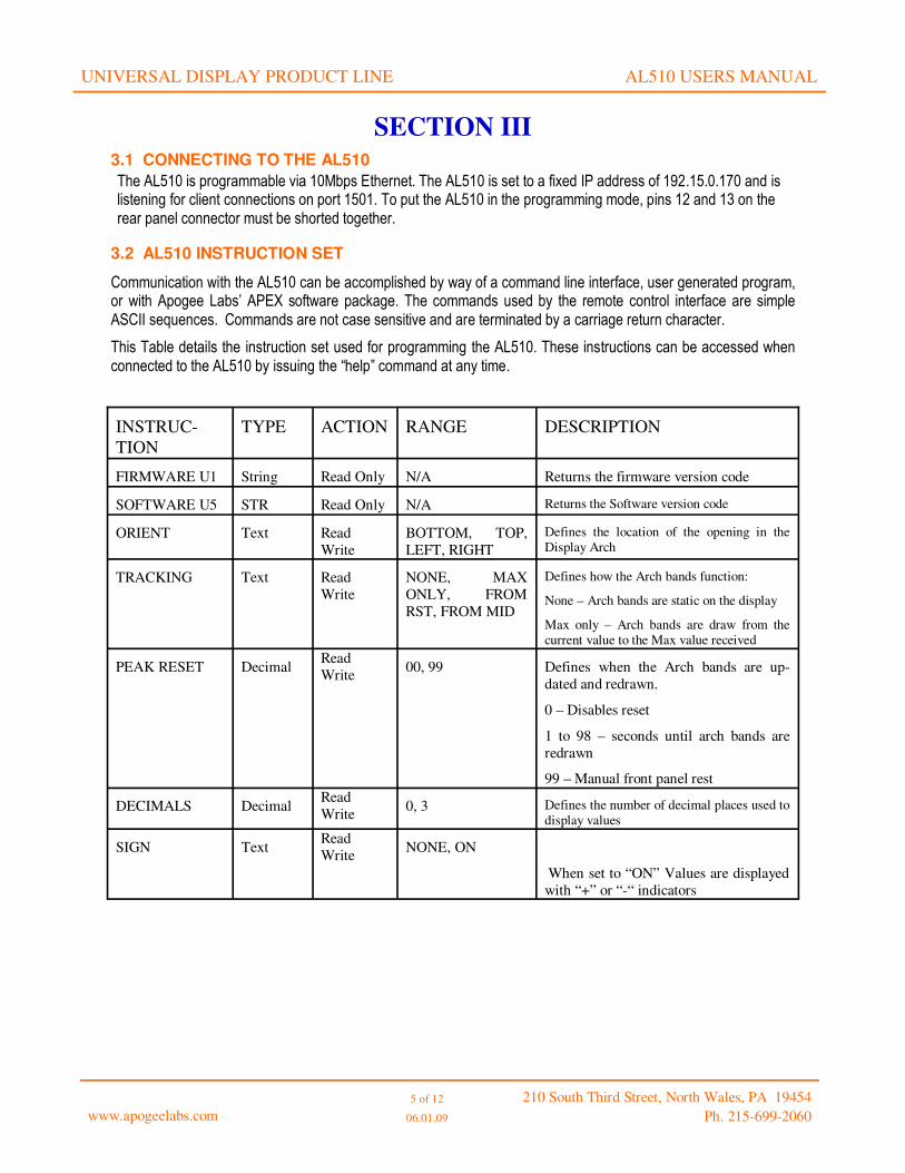
3.2 AL510 INSTRUCTION SET
Communication with the AL510 can be accomplished by way of a command line interface, user generated program, or with Apogee Labs’ APEX software package. The commands used by the remote control interface are simple ASCII sequences. Commands are not case sensitive and are terminated by a carriage return character.
This Table details the instruction set used for programming the AL510. These instructions can be accessed when connected to the AL510 by issuing the “help” command at any time.
INSTRUC-
TION
TYPE ACTION RANGE DESCRIPTION
FIRMWARE U1 String Read Only N/A Returns the firmware version code
SOFTWARE U5 STR Read Only N/A Returns the Software version code
ORIENT Text Read
Write
BOTTOM, TOP,
LEFT, RIGHT
Defines the location of the opening in the Display Arch
TRACKING Text Read
Write
NONE, MAX
ONLY, FROM
RST, FROM MID
Defines how the Arch bands function:
None – Arch bands are static on the display
Max only – Arch bands are draw from the current value to the Max value received
PEAK RESET Decimal Read
Write 00, 99 Defines when the Arch bands are up-
dated and redrawn.
0 – Disables reset
1 to 98 – seconds until arch bands are
redrawn
99 – Manual front panel rest
DECIMALS Decimal Read
Write 0, 3 Defines the number of decimal places used to
display values
SIGN Text Read
Write NONE, ON
When set to “ON” Values are displayed
with “+” or “-“ indicators

UNIVERSAL DISPLAY PRODUCT LINE AL510 USERS MANUAL
www.apogeelabs.com 6 of 12
06.01.09 210 South Third Street, North Wales, PA 19454
Ph. 215-699-2060
LOW VALUE Decimal Read
Write -999, 999 Sets the starting value of the display
HIGH VALUE Decimal Read
Write -999, 999 Sets the end value of the display
INTERVAL Decimal Read
Write 001, 512 Sets the interval between Tick marks
with numerical values
TICK MARKS:
Decimal Read
Write 000, 999 Set the interval between tick marks with-
out numerical values
INPUT SEL Decimal Read
Write 1, 4 Selects the input channel to be used.
AVERAGE
Decimal Read
Write 000, 100 Sets the numbers of measurements to be
average prior to updating the display
INDICATOR
Text Read
Write ARC, POINTER Selects the indicator type.
Arch type fills in the area from the start
of the arch to the current value.
UNITS
String Read
Write 0,8 User settable eight character string displayed
above the current value field
MNEMONIC
String Read
Write 0,8 User settable eight character string displayed
below the current value field
STARTn
n=1,2,3,4,5,6
Decimal Read
Write 00, 99 Sets the start point of Arch band 1. The
value is set in percent of the Display
arch to start from. Setting this value to
50 would start the arch at the middle of
the display arch.
COLORn
n=1,2,3,4,5,6
Text Read
Write DK_BLU, GREEN,
BLUE, YEL-
LOW,GREY, RED,
WHITE
Sets the color to be used for the selected
arch.
PROGRAM Text Read
Write EDIT, RECALL,
COMMIT
This sets the programming mode. De-
fault mode is Edit when the program-
ming pins are jumpered together.
Commit is used to move the temporary
working memory into nonvolatile mem-ory.
Recall moves the nonvolatile memory
into the temporary working memory.
COPY CHNL
Text Read
Write 1, 2, 3, 4 Copy the settings from another channel
into the current channel. Note: the infor-
mation copied needs to be committed
nonvolatile memory
FACTORY SET Text Read
Write OFF, SET Resets the displays to factory default
settings. Note: After being reset the
touch screen needs to be recalibrated
TS VALUES
Decimal Read
Write 00000, 65535 Displays the current value of the touch
screen. This is used to calibrate the touch
screen.

UNIVERSAL DISPLAY PRODUCT LINE AL510 USERS MANUAL
3.3 REMOTE CONTROL COMMAND RESPONSE
All commands are terminated with a carriage return. A response will always occur when a command is issued. The response of a properly formatted command will end with a “>” and when an invalid instruction is issued, the response is a question mark “?”. A valid response is prefaced with the value “set” or “read”. i.e. The command “set color5=Green” results in the flowing response:
COLOR5: GREEN
>
www.apogeelabs.com 7 of 12
06.01.09 210 South Third Street, North Wales, PA 19454
Ph. 215-699-2060
SECTION III
3.4 HELP COMMAND
After issuing the SLOT=n command to address the module, issuing the HELP command results in the listing shown in Table 8. This is a list of all instructions and their character that are associated with the BERT1 module. Each item in the list reveals an instruction and the characteristics of its associated information. The syntax of the listings is:<instruction>, <value type>, <action>, <value>, <value>, … <value>. From this information, the user is able to determine the type of parameter and the range of values that are assignable to each instruction. The definition of each field in the HELP instruction listing is: <instruction>: The name of the instruction, such as Color5 delimited by a colon <value type>, Defines the type of information associated with the instruction, such as DEC for decimal number, TXT for fixed text value, and STR for non fixed text values .
<action>, Identifies the instruction as being capable of read-only (RO) or read / write (RW).
<value>, The “value(s)” are a list or range of entries that are acceptable to the instruction. In the case of
the TS VALUES: DEC, RW, ,00000, 65535 equates to a acceptable value range of between 0 and 65535 decimal.
3.5 SET COMMAND
To write a value into a parameter register, the instruction is preceded by the SET command followed by a space. For example, to change the color of Arch1 of the display, the instruction takes the form: SET COLOR1=RED <CR>. Where: “SET” specifies a write operation, “BIT RATE” is the instruction that is to be changed, “=” is the delimiter between the instruction name and the value, “RED” is the text value to be written, <CR> symbolizes the carriage return terminator. Upon successfully executing the command, the unit echoes the result in the form: COLOR1:RED > where “>” is the system command line cursor.
3.6 READ COMMAND
Interrogating a parameter is accomplished using the READ command. The format of a READ is: READ <instruction> <CR>. If the command is successful, the parameter name and its value are returned followed by a carriage return and the “>” symbol.

UNIVERSAL DISPLAY PRODUCT LINE AL510 USERS MANUAL
3.7 SYSTEM LEVEL COMMANDS
Some commands stand-alone. These are listed in the table below and are accessed via the “Commands” in-struction.
www.apogeelabs.com 8 of 12
06.01.09 210 South Third Street, North Wales, PA 19454
Ph. 215-699-2060
INSTRUCTION MEANING
SLOT Lists the current slot in use.
List Slots List the slots available in the unit. This is fixed in the AL510 and returns
the following values.
SLOTS
01 - CHANNEL1, AL510, 1.0
02 - CHANNEL2, AL510, 1.0
03 - CHANNEL3, AL510, 1.0
04 - CHANNEL4, AL510, 1.0
SLOT=n Selects the slot location to be accessed
READ aaa Is the read command
SET aaa=xx Is the write command
FPUpdate Refreshes the display using currnet values.
Note: the Programm=Commit commands must be issued prior to changing
the slot in order to save the settings.
Quit Exit Closes the Socket connection.
Note: “Quit” or “Exit” can be used to close the connection.

UNIVERSAL DISPLAY PRODUCT LINE AL510 USERS MANUAL
3.8 APEX PROGRAMMING
Programming of the unit is simplified through the use of the Apogee Labs’ APEX remote control software. When using the APEX software, the user only needs to connect to the unit from a computer on the 192.15.0.XX network to begin configuring displays.
www.apogeelabs.com 9 of 12
06.01.09 210 South Third Street, North Wales, PA 19454
Ph. 215-699-2060
1) After starting the APEX software, select “Setup” > Add Node
2) Select AL510 from the pull down menu

UNIVERSAL DISPLAY PRODUCT LINE AL510 USERS MANUAL
www.apogeelabs.com 10 of 12
06.01.09 210 South Third Street, North Wales, PA 19454
Ph. 215-699-2060
3) Enter the IP address 192.15.0.170 and select the “Connect” button. If the network is configured correctly, the status will show “connected”. (Note: The program pins on the rear panel connector must be shorted together in order to connect to the unit)
4) Select “Get Slot Configuration” to populate the node with the four displays. Each display is fixed to a slot loca-tion. (i.e: Slot 1 = Channel 1 (First Display))

UNIVERSAL DISPLAY PRODUCT LINE AL510 USERS MANUAL
www.apogeelabs.com 11 of 12
06.01.09 210 South Third Street, North Wales, PA 19454
Ph. 215-699-2060
5) Once the unit has self configured, select the channel that you want to configure.
6) APEX will then read the configuration from the channel selected. On subsequent connections, the software will load the last configuration used and will prompt the user to load the configuration.
At this point the user can modify the configuration. In order to view the effects of the changes, the user would select the “Redraw” button. This button will cause the display to refresh with the new settings. When satisfied with the dis-play configuration, the user needs to select the “Commit” to commit the values to non-volatile memory. If the user wants to revert to the initial settings, the “Recall” button may be selected, or simply move to another channel without hitting the commit button. After changing channels, using the recall button, or the commit button it is recommended the user select the “Redraw” button to ensure the current display is visible.

UNIVERSAL DISPLAY PRODUCT LINE AL510 USERS MANUAL
www.apogeelabs.com 12 of 12
06.01.09 210 South Third Street, North Wales, PA 19454
Ph. 215-699-2060
All value settings are on a per channel basis and fully independent of the other channel(s) configurations. (i.e. Dis-play channels can all be set to use the same or different input channels.) Use of the front panel touch screen while in the program mode could result in dropped socket connections and should be avoided. Should this occur, it is recommended that the AL510 be rebooted in order to regain socket con-nections and maintain display configuration.
SECTION IV
4.1 MAIN DISPLAY OPERATION
The AL510 will boot to the Channel 1 display when power is applied. At this point, the unit is fully functional. The only user configuration allowed when in the operational mode is via the front panel touch screen. The touch screen is divided evenly into four buttons. They are fixed in location and function. See Figure 4 below. The four buttons on the main displays are: Brite, Dim, RST Peak and CHN.
Brite causes the display to get progressively brighter. After maximum bright-ness, the unit will rollover to minimum brightness. Dim causes the display to get progressively dimmer. After minimum brightness, the unit will rollover to maximum brightness. RST Peak depends on the tracking and peak rest configuration and will manu-ally reset the maximum values color bands. CHN takes the user to the Display Channel selection page.
The Channel selection page (Figure 5) is divided into four sections and pressing anywhere in the requested channel descriptor for approximately one second will display the indicator configured for that channel.
Figure 4
Figure 5