Embed Size (px)
Citation preview

Model 918D Series
Photodiode Detectors
User ’s Manual
44640-02RevD 5-5x7-5_44640-01RevA 5-5x7-5.qxd 8/12/10 3:15 PM Page 1

44640-02RevD 5-5x7-5_44640-01RevA 5-5x7-5.qxd 8/12/10 3:15 PM Page 2

Model 918D SeriesPhotodiode Detectors
Dear Customer,
This User Manual contains essential information, including safety precautions andstart up procedures, needed to get your new instrument up and running. Pleasereview it prior to unpacking and powering up the instrument.
In an effort to keep the Newport instruments optimized for your applications,Newport will on occasion update existing and add new features and documents. Youcan find the latest User Manual, application software, Start-up Guide, or firmware atthe product page on the Newport website (www.newport.com). Call your localNewport application specialist if you need support with locating or downloadingthese files.
Enjoy your new product!
44640-02RevD 5-5x7-5_44640-01RevA 5-5x7-5.qxd 8/12/10 3:15 PM Page i

ii
Warranty
Newport Corporation warrants that this product will be free from defects in materialand workmanship and will comply with Newport’s published specifications at thetime of sale for a period of one year from date of shipment. If found to be defectiveduring the warranty period, the product will either be repaired or replaced atNewport's option.
To exercise this warranty, write or call your local Newport office or representative, or contact Newport headquarters in Irvine, California. You will be given promptassistance and return instructions. Send the product, freight prepaid, to the indicatedservice facility. Repairs will be made and the instrument returned freight prepaid.Repaired products are warranted for the remainder of the original warranty period or90 days, whichever first occurs.
Limitation of Warranty
The above warranties do not apply to products which have been repaired or modifiedwithout Newport’s written approval, or products subjected to unusual physical, thermal or electrical stress, improper installation, misuse, abuse, accident or negli-gence in use, storage, transportation or handling. This warranty also does not applyto fuses, batteries, or damage from battery leakage.
THIS WARRANTY IS IN LIEU OF ALL OTHER WARRANTIES, EXPRESSED ORIMPLIED, INCLUDING ANY IMPLIED WARRANTY OF MERCHANTABILITYOR FITNESS FOR A PARTICULAR USE. NEWPORT CORPORATION SHALLNOT BE LIABLE FOR ANY INDIRECT, SPECIAL, OR CONSEQUENTIAL DAMAGES RESULTING FROM THE PURCHASE OR USE OF ITS PRODUCTS.
First printing 2006
© 2005 by Newport Corporation, Irvine, CA. All rights reserved. No part of thismanual may be reproduced or copied without the prior written approval of NewportCorporation.
This manual has been provided for information only and product specifications aresubject to change without notice. Any change will be reflected in future printings.
Newport Corporation1791 Deere AvenueIrvine, CA, 92606, USAPart No. 44640-02, Rev. D
44640-02RevD 5-5x7-5_44640-01RevA 5-5x7-5.qxd 8/12/10 3:15 PM Page ii

iii
Confidentiality & Proprietary Rights
Reservation of Title:
The Newport programs and all materials furnished or produced in connection withthem ("Related Materials") contain trade secrets of Newport and are for use only inthe manner expressly permitted. Newport claims and reserves all rights and benefitsafforded under law in the Programs provided by Newport Corporation.
Newport shall retain full ownership of Intellectual Property Rights in and to all devel-opment, process, align or assembly technologies developed and other derivative workthat may be developed by Newport. Customer shall not challenge, or cause any thirdparty to challenge the rights of Newport.
Preservation of Secrecy and Confidentiality and Restrictions to Access:
Customer shall protect the Newport Programs and Related Materials as trade secretsof Newport, and shall devote its best efforts to ensure that all its personnel protect theNewport Programs as trade secrets of Newport Corporation. Customer shall not atany time disclose Newport's trade secrets to any other person, firm, organization, oremployee that does not need (consistent with Customer's right of use hereunder) toobtain access to the Newport Programs and Related Materials. These restrictionsshall not apply to information (1) generally known to the public or obtainable frompublic sources; (2) readily apparent from the keyboard operations, visual display, oroutput reports of the Programs; 3) previously in the possession of Customer or subse-quently developed or acquired without reliance on the Newport Programs; or (4)approved by Newport for release without restriction.
Service Information
This section contains information regarding factory service for the source. The usershould not attempt any maintenance or service of the system or optional equipmentbeyond the procedures outlined in this manual. Any problem that cannot be resolvedshould be referred to Newport Corporation.
44640-02RevD 5-5x7-5_44640-01RevA 5-5x7-5.qxd 8/12/10 3:15 PM Page iii

iv
Technical Support Contacts
North America & Asia EuropeNewport Corporation Service Dept. Newport/MICRO-CONTROLE S.A.1791 Deere Ave. Irvine, CA 92606 Zone IndustrielleTelephone: (949) 253-1694 45340 Beaune la Rolande, FRANCETelephone: (800) 222-6440 x31694 Telephone: (33) 02 38 40 51 56
Asia
253 Aidu Road, Bld #3, Flr 3, Sec C Shanghai 200131, ChinaTelephone: +86-21-5046 2300Fax: +86-21-5046 2323
Newport Corporation Calling Procedure
If there are any defects in material or workmanship or a failure to meet specifica-tions, promptly notify Newport's Returns Department by calling
1-800-222-6440 or by visiting our website at www.newport.com/returns within thewarranty period to obtain a Return Material Authorization Number (RMA#). Returnthe product to Newport Corporation, freight prepaid, clearly marked with the RMA#and we will either repair or replace it at our discretion. Newport is not responsiblefor damage occurring in transit and is not obligated to accept products returned with-out an RMA#.
E-mail: [email protected]
When calling Newport Corporation, please provide the customer care representative-with the following information:
• Your Contact Information• Serial number or original order number • Description of problem (i.e., hardware or software)
To help our Technical Support Representatives diagnose your problem, please notethe following conditions:
• Is the system used for manufacturing or research and development?• What was the state of the system right before the problem?• Have you seen this problem before? If so, how often?• Can the system continue to operate with this problem? Or is the system non-operational?
• Can you identify anything that was different before this problem occurred?
44640-02RevD 5-5x7-5_44640-01RevA 5-5x7-5.qxd 8/12/10 3:15 PM Page iv

Table of Contents
Warranty ..............................................................................................iiTechnical Support Contacts........................................................................ivTable of Contents ........................................................................................1List of Figures ............................................................................................1
Section 1 — General Information
1.1 Unpacking and Inspection ....................................................21.2 Photodetector Features ..........................................................21.3 Photodetector Specifications ................................................41.4 Making Measurements ..........................................................61.5 Optional Accessories ............................................................91.6 Cleaning ..............................................................................101.6 Temperature and Humidity..................................................11
Section 2 — Calibration Accuracy and Limitations
2.1 Spectral Response................................................................122.2 Calibration Accuracy and Service ......................................122.3 Uniformity ..........................................................................132.4 Saturation ............................................................................132.5 Saturation with Pulsed Power Measurements ....................142.6 Reflections ..........................................................................142.7 Photodiode Operation..........................................................152.8 Low Power Measurement Considerations ..........................162.8.1 Noise Characteristics ..........................................................162.8.2 Ambient Light and Electrical Offsets ..................................172.9 Using the Detector for Non-CW Measurements ................18
Section 3 — Service Form
List of Figures
Figure 1 Attenuator ‘ON/OFF’ dial ....................................................8Figure 2 Model 918D-Base-Kit ..........................................................9Figure 3 Cleaning Detector Optics ....................................................10Figure 4 Transimpedance Amplifier ..................................................15
1
44640-02RevD 5-5x7-5_44640-01RevA 5-5x7-5.qxd 8/12/10 3:15 PM Page 1

2
General Information
This guide contains information necessary for using model 918D seriesphotodetectors. Please read through the guide before attempting tomake optical power measurements or energy measurements.
1.1 Unpacking and Inspection
The 918D photodetectors are shipped in a foam padded cardboard box.The user’s manual and the calibration report are also included. The cal-ibration report is unique to each detector and should be archived forfuture reference. The calibration interval recommended for these detec-tors is 12 months. Please make sure that these items are received ingood condition.
NOTEThe only user serviceable part of this detector is the cleaning ofthe internal attenuator filter and detector window. See Section
1.6 for a description on how to clean these parts.
1.2 Photodetector Features
918D series detectors utilize Silicon, extended Silicon, Germanium,and InGaAs photodiodes covering a broad wavelength range from200nm to 1800nm. These highly sensitive, low-noise semiconductorphotodiodes enable measurements from the milli-Watt down to thefemto-Watt regime. The built-in attenuator extends this range up into the200mW to 10W range.
44640-02RevD 5-5x7-5_44640-01RevA 5-5x7-5.qxd 8/12/10 3:15 PM Page 2

3
The 918D detectors are terminated with a 15-pin D-Sub type connec-tor and are designed for use with Newport’s optical meter families:
• 1928-C, 1935/2935-C, 1936/2936-C Series HighPerformance Optical Power/Energy Meters ( Including the1935T-C, 2935T-C and 2935T-C-1)
• 1931/2931-C Series High Performance Optical Power Meters
• 1918-C High-Performance Handheld Optical Power/Energy Meter
• 842-PE Handheld Optical Power/Energy Meter
• 1916-C Handheld Optical Power Meter
The 918D-IG-C1 cooled InGaAs detector can only be used with the1935T-C, 2935T-C and 2935T-C-1 optical meters, which include aThermo-Electric Cooler (TEC) Controller card. The detector has anadditional cable, terminated with a 9-pin D-Sub type connector, fordriving the TEC inside the detector head.
1.3
44640-02RevD 5-5x7-5_44640-01RevA 5-5x7-5.qxd 8/12/10 3:15 PM Page 3
4
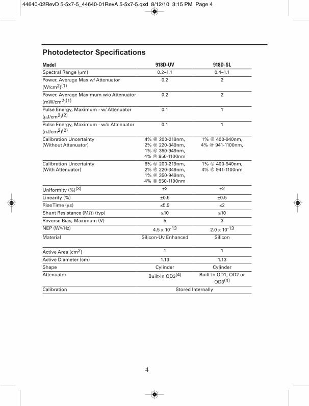
Photodetector Specifications
Model 918D-UV 918D-SLSpectral Range (μm) 0.2–1.1 0.4–1.1
Power, Average Max w/ Attenuator
(W/cm2)(1)0.2 2
Power, Average Maximum w/o Attenuator
(mW/cm2)(1)0.2 2
Pulse Energy, Maximum - w/ Attenuator
(μJ/cm2)(2)0.1 1
Pulse Energy, Maximum - w/o Attenuator
(nJ/cm2)(2)0.1 1
Calibration Uncertainty (Without Attenuator)
4% @ 200-219nm, 2% @ 220-349nm, 1% @ 350-949nm,4% @ 950-1100nm
1% @ 400-940nm, 4% @ 941-1100nm,
Calibration Uncertainty (With Attenuator)
8% @ 200-219nm, 2% @ 220-349nm, 1% @ 350-949nm, 4% @ 950-1100nm
1% @ 400-940nm, 4% @ 941-1100nm
Uniformity (%)(3) ±2 ±2
Linearity (%) ±0.5 ±0.5
Rise Time (μs) ≤5.9 ≤2
Shunt Resistance (MΩ) (typ) ≥10 ≥10
Reverse Bias, Maximum (V) 5 3
NEP (W/√Hz) 4.5 x 10⁻¹³ 2.0 x 10⁻¹³
Material Silicon-Uv Enhanced Silicon
Active Area (cm2) 1 1
Active Diameter (cm) 1.13 1.13
Shape Cylinder Cylinder
Attenuator Built-In OD3(4) Built-In OD1, OD2 or
OD3(4)
Calibration Stored Internally
44640-02RevD 5-5x7-5_44640-01RevA 5-5x7-5.qxd 8/12/10 3:15 PM Page 4
5
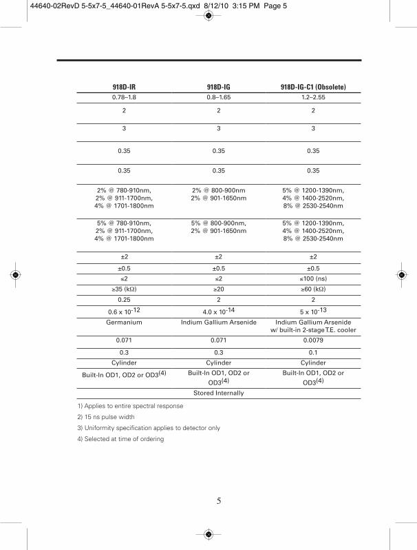
±2 ±2 ±2
918D-IR 918D-IG 918D-IG-C1 (Obsolete)0.78–1.8 0.8–1.65 1.2–2.55
2 2 2
3 3 3
0.35 0.35 0.35
0.35 0.35 0.35
2% @ 780-910nm,2% @ 911-1700nm, 4% @ 1701-1800nm
2% @ 800-900nm2% @ 901-1650nm
5% @ 1200-1390nm, 4% @ 1400-2520nm, 8% @ 2530-2540nm
5% @ 780-910nm, 2% @ 911-1700nm, 4% @ 1701-1800nm
5% @ 800-900nm, 2% @ 901-1650nm
5% @ 1200-1390nm, 4% @ 1400-2520nm, 8% @ 2530-2540nm
±0.5 ±0.5 ±0.5
≤2 ≤2 ≤100 (ns)
≥35 (kΩ) ≥20 ≥60 (kΩ)
0.25 2 2
0.6 x 10⁻¹² 4.0 x 10⁻¹⁴ 5 x 10-13
Germanium Indium Gallium Arsenide Indium Gallium Arsenide w/ built-in 2-stage T.E. cooler
0.071 0.071 0.0079
0.3 0.3 0.1
Cylinder Cylinder Cylinder
Built-In OD1, OD2 or OD3(4) Built-In OD1, OD2 or
OD3(4)Built-In OD1, OD2 or
OD3(4)
Stored Internally
1) Applies to entire spectral response
2) 15 ns pulse width
3) Uniformity specification applies to detector only
4) Selected at time of ordering
44640-02RevD 5-5x7-5_44640-01RevA 5-5x7-5.qxd 8/12/10 3:15 PM Page 5

6
1.4 Making Measurements
918D series photodetectors are terminated with a 15-pin D-Sub con-nector, which needs to be attached to the back or side panels ofNewport’s optical meters. In order to assure good electrical connectiv-ity, it is recommended that the thumbscrews located on both sides ofthe connector be hand-tightened.
Each detector comes with its unique calibrated responsivity dataencoded in an EEPROM built into the detector body. Calibration datais provided for the detector with and without the optical attenuator.Newport’s 1936/2936 series of optical meters read the EEPROM datanot only during initial power-up, but at any time a detector is con-nected to, and subsequently sensed by the optical meter.
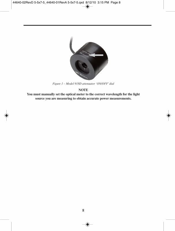
The 918D series photodetectors have a built-in optical attenuator,which can be manually switched into or out of the optical path usinga thumb-wheel located on top of the detector housing. Attenuator‘ON’ and ‘OFF’ markings indicate the turning direction. A built-insensor automatically detects the attenuator position, signaling theinstrument to use the appropriate responsivity for the detector/attenu-ator combination.
The 918D-IG-C1 cooled InGaAs detector is terminated with twocables. The first one is identical to the cable on the standard 918Dseries detectors, and is terminated with a 15-pin D-Sub connector. Thesecond cable is terminated with a 9-pin D-Sub connector and needs tobe attached to the TEC Controller card of the 1935T-C, 2935T-C or2935T-C-1 optical meters. Upon turning on the power meter, the TECinside the detector head will start cooling down the photodiode to thefactory preset temperature. A temperature sensor inside the photodiodehousing provides the actual temperature reading back to the controllercard, which will maintain the temperature at the optimal level. Theinstrument front panel display will indicate when the optimal tempera-ture level is attained, at which point the detector is ready for takingmeasurements. The detector temperature will typically settle within afew seconds after the detector is plugged into the instrument.
44640-02RevD 5-5x7-5_44640-01RevA 5-5x7-5.qxd 8/12/10 3:15 PM Page 6
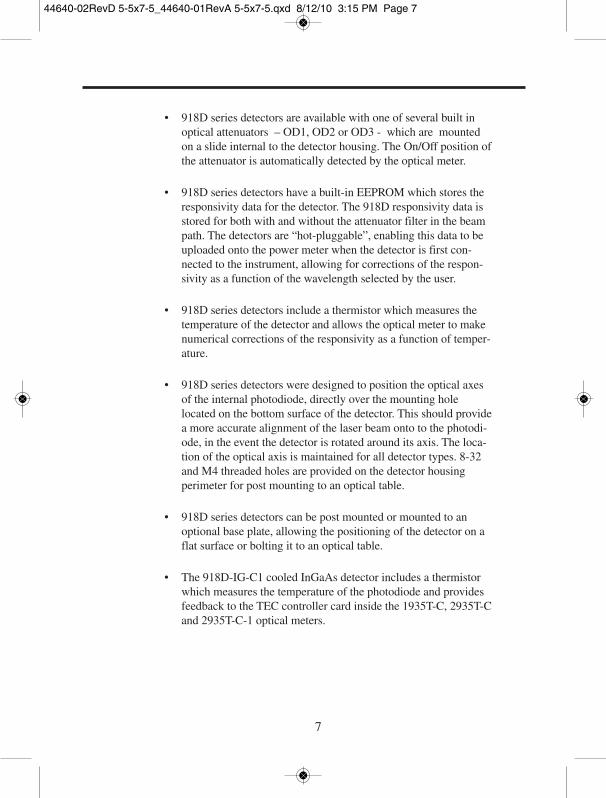
7
• 918D series detectors are available with one of several built inoptical attenuators – OD1, OD2 or OD3 - which are mountedon a slide internal to the detector housing. The On/Off position ofthe attenuator is automatically detected by the optical meter.
• 918D series detectors have a built-in EEPROM which stores theresponsivity data for the detector. The 918D responsivity data isstored for both with and without the attenuator filter in the beampath. The detectors are “hot-pluggable”, enabling this data to beuploaded onto the power meter when the detector is first con-nected to the instrument, allowing for corrections of the respon-sivity as a function of the wavelength selected by the user.
• 918D series detectors include a thermistor which measures thetemperature of the detector and allows the optical meter to makenumerical corrections of the responsivity as a function of temper-ature.
• 918D series detectors were designed to position the optical axesof the internal photodiode, directly over the mounting holelocated on the bottom surface of the detector. This should providea more accurate alignment of the laser beam onto to the photodi-ode, in the event the detector is rotated around its axis. The loca-tion of the optical axis is maintained for all detector types. 8-32and M4 threaded holes are provided on the detector housingperimeter for post mounting to an optical table.
• 918D series detectors can be post mounted or mounted to anoptional base plate, allowing the positioning of the detector on aflat surface or bolting it to an optical table.
• The 918D-IG-C1 cooled InGaAs detector includes a thermistorwhich measures the temperature of the photodiode and providesfeedback to the TEC controller card inside the 1935T-C, 2935T-Cand 2935T-C-1 optical meters.
44640-02RevD 5-5x7-5_44640-01RevA 5-5x7-5.qxd 8/12/10 3:15 PM Page 7
8
Figure 1 – Model 918D attenuator ‘ON/OFF’ dial
NOTEYou must manually set the optical meter to the correct wavelength for the light
source you are measuring to obtain accurate power measurements.
8
44640-02RevD 5-5x7-5_44640-01RevA 5-5x7-5.qxd 8/12/10 3:15 PM Page 8

9
1.5 Optional Accessories
Base PlateA base plate kit (Model 918D-Base-Kit), consisting of the plate andmounting screws, is available for using the detector on a flat surface oroptical table. A total of 5 screws are provided: 1 set screw to attachthe base plate to the detector and 4 screws for attaching the plate to anoptical table (2 Metric and 2 English)
Figure 2 – Model 918D mounted on Base
44640-02RevD 5-5x7-5_44640-01RevA 5-5x7-5.qxd 8/12/10 3:15 PM Page 9
10
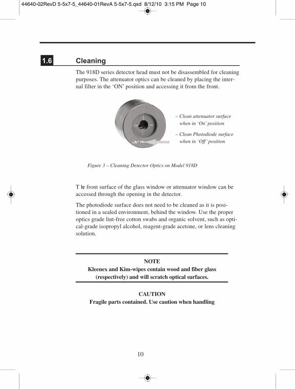
1.6 Cleaning
The 918D series detector head must not be disassembled for cleaningpurposes. The attenuator optics can be cleaned by placing the inter-nal filter in the ‘ON’ position and accessing it from the front.
Figure 3 – Cleaning Detector Optics on Model 918D
T he front surface of the glass window or attenuator window can beaccessed through the opening in the detector.
The photodiode surface does not need to be cleaned as it is posi-tioned in a sealed environment, behind the window. Use the properoptics grade lint-free cotton swabs and organic solvent, such as opti-cal-grade isopropyl alcohol, reagent-grade acetone, or lens cleaningsolution.
NOTEKleenex and Kim-wipes contain wood and fiber glass
(respectively) and will scratch optical surfaces.
CAUTIONFragile parts contained. Use caution when handling
– Clean attenuator surfacewhen in ‘On’ position
– Clean Photodiode surfacewhen in ‘Off’ position
44640-02RevD 5-5x7-5_44640-01RevA 5-5x7-5.qxd 8/12/10 3:15 PM Page 10

11
Care should be taken not to touch the photodiode window or attenuator with bare fingers. Contaminants may cause inaccuratemeasurements, particularly at ultraviolet wavelengths where absorption is common.
Potentially large measurement errors can be induced by scratches,digs and damage to the optical surfaces of the attenuator or detector.For dust removal, use pressurized gas (filtered dry nitrogen) and lint-free cotton swabs dabbed in an organic solvent.
1.7 Temperature and Humidity
The temperature range of +5 to +50°C should not be exceeded andthe detector should not be exposed to humidity levels greater than70%. The photodiode sensitivity increases with temperature, mainlyfor wavelengths longer than the peak response wavelength. Thetemperature of the 918D series detectors is monitored with a ther-mistor and the responsivity is numerically compensated to keep thecalibration accurate within specification throughout the operatingtemperature for certain wavelengths.
44640-02RevD 5-5x7-5_44640-01RevA 5-5x7-5.qxd 8/12/10 3:15 PM Page 11

12
2 Calibration Accuracy and Limitations
2.1 Spectral Response
The response of the detector depends on the wavelength of the inci-dent light. The photodiode is transparent for photon energies lessthan the band gap which determines the long wavelength infraredsensitivity limit. The short wavelength limit is determined by thephotodiode manufacturing process and possibly, in the case of siliconphotodiodes, by strong window absorption. The photodiode responseis commonly measured in amps of photocurrent per watt of incidentoptical power. The response curves for the photodetector are shownon the calibration report.
2.2 Calibration Accuracy and Service
Statement of Calibration: The accuracy and calibration ofthis photodetector are traceable to National Institute of
Standards and Technology (NIST) and/or National ResearchCouncil of Canada (NRC) through equipment which is
calibrated at planned intervals by comparison to certified stan-dards maintained at Newport Corporation.
Newport Corporation calibrates its detectors using secondary standards directly traceable to NIST and/or NRC. The absolute accuracy of the photodetector calibration is indicated on the calibra-tion report. Detector response can change with time at different wave-lengths, especially in the ultraviolet, and should be returned for recali-bration at one year intervals to ensure confidence in the accuracy ofthe measurement.
For recalibration services, contact Newport Corporation at 800-222-6440.
44640-02RevD 5-5x7-5_44640-01RevA 5-5x7-5.qxd 8/12/10 3:15 PM Page 12

2.3 Uniformity
Fabrication processes may cause the response of the detector to varyslightly over the detector surface. Calibration involves illumination ofapproximately 70% of the detector’s central active diameter. Opticalsignals being measured should illuminate approximately this samearea. Care should be taken not to overfill the detector if accuracy is tobe maintained.
2.4 Saturation
For low optical power the photocurrent is linearly proportional to theoptical signal incident on the photodiode. For high optical powers saturation of the detector begins to occur and the response signal is nolonger linearly proportional to the incident power. Optical power mea-surements must be made in the linear region to be valid. Newport’soptical meters measure the current coming from the detector and willlet you know before the detector is near its saturation point. However,it is possible to locally saturate the detector by subjecting it to highpower densities (power per unit area). This is why it is important to fillthe central portion of the detector’s active area as much as possible.
NOTEThe saturation is “soft”, i.e. the detector output does not
suddenly stop increasing, but the rate of increase slows. ForGaussian and other signals with spatially varying intensities,local saturation may occur. The onset of saturation is notalways obvious and is a common source of inaccurate
measurements.
13
44640-02RevD 5-5x7-5_44640-01RevA 5-5x7-5.qxd 8/12/10 3:15 PM Page 13

14
To determine if the detector is saturating, follow the steps below:
1. Measure the photodetector current (or power), and record this value (A).
2. Place a filter or attenuator of known transmission (T) in the beampath. Record the current again (B). A filter transmission of 0.001 is aconvenient choice.
3. The power with the filter in place should be the product of the powermeasured without the filter and the transmission of the filter, i.e. B = A x T.
If the transmission (T) of the filter is not known, it can be determined by followingthe steps below:
1. Reduce the optical power to a level low enough to avoid saturation,but high enough that, when it is reduced by the filter it can still beaccurately measured.
2. Follow steps 1 and 2 in the procedure above.
3. Calculate the ratio T = B/A to determine the transmission of the filterat the wavelength of light used for the measurement.
The calibrated filter (or attenuator) can be used with the detector tomeasure the power of higher power beams.
2.5 Saturation with Pulsed Power Measurements
Saturation effects are a complex phenomenon, when using pulsedlasers and depend upon the wavelength, peak power, pulse shape,average power, repetition rate, and on the type of detection circuit.However, the test for saturation described immediately above shouldbe used whenever pulsed power measurements are being made.
2.6 Reflections
The photodetector surface, window material and the attenuator allreflect light. The amount of reflected light depends upon the angle ofincidence and the polarization of the beam. Reflected light does notget absorbed by the detector, and therefore is not included in thedetector signal. The Newport detector and attenuator calibrationinclude the loss due to reflection for incoherent light incident normalto the detector. For accurate power measurements the detector shouldtherefore be used at near normal incidence.
44640-02RevD 5-5x7-5_44640-01RevA 5-5x7-5.qxd 8/12/10 3:15 PM Page 14

15
2.7 Photodiode Operation
When a photon is absorbed in the photodiode, an electron-hole pair isformed within the device and a voltage is developed across the diodejunction. If the photodiode terminals are
44640-02RevD 5-5x7-5_44640-01RevA 5-5x7-5.qxd 8/12/10 3:15 PM Page 15

16
2.8 Low Power Measurement Considerations
Measurements of very low power optical sources are possible with918D series photodetectors. To use the detector properly and achieveaccurate results requires the understanding of a number of effects thatlimit the device performance which are discussed below.
2.8.1 Noise Characteristics
The lower limits of optical detection are determined by the noise char-acteristics of the detector and/or amplifier. Theory predicts that thephotodiode noise is largely thermal (Johnson) noise associated withthe effective resistance of the photodiode and shot noise from darkcurrent. Additionally, there is Johnson noise contributed by the resis-tance of the amplifier’s feedback resistor. The dark current at a 10mVbias voltage is measured and used to define the effective resistance ofthe photodiode, known as the shunt resistance:
Rshunt = Vbias / Idark where Vbias = 10mV
Ideally an input amplifier connected as in Figure 4 would have no off-set voltage and there would be no dark current. In practice though, asmall bias usually exists. For non-CW measurements the light detec-tion limit is more generally expressed as the intensity of light requiredto produce a current equal to the noise current, i.e. a signal-to-noiselevel of 1. This is called the noise equivalent power (NEP) and isexpressed as:
NEP = Noise Current/Sensitivity (W/√Hz )
with sensitivity defined as the current generated by the photodiode fora given incident power, at a specific wavelength. NEP varies inverselywith the spectral response of the photodiode and depends on the wave-length, �, the noise frequency, f, and bandwidth, ∆f.
Noise and dark current generally increase exponentially with detectortemperature so it is best to keep the temperature close to 25°C.
44640-02RevD 5-5x7-5_44640-01RevA 5-5x7-5.qxd 8/12/10 3:15 PM Page 16

17
2.8.2 Ambient Light and Electrical Offsets
Good measurement technique dictates that the effects of ambient lightshould be reduced as much as possible when using photodiodes.Although the photocurrent generated by ambient light can be easilyzeroed out, the shot noise associated with the photocurrent will not bezeroed, nor will any changes in the ambient light levels, which mightbe caused by people moving around in the room. A small electronicoffset will always be present with semiconductor detectors, caused byan interaction of the detector shunt resistance with voltage offsets inthe amplifier circuitry. The offset can be removed by use of the opticalmeter’s zero function. Please note, however, that the offset is a func-tion of the temperature of both the photodiode and the amplifier insidethe optical meter.
When measuring very low light levels, it is best to re-zero the meterwhenever you think that the temperature of the detector or the opticalmeter may have changed. For instance, it is good practice to re-zerothe meter after a warm-up period of about 30 minutes. Refer to youroptical meter manual for details regarding the zeroing procedure.
All 918D series photodetectors have a threaded aperture for the attach-ment of accessories. When measurements of power in fiber optics arebeing made, the effects of ambient lighting can be minimized by usingthe Model 818-FA Fiber Adapter Holder with the appropriate FP3 orFP4 series fiber adapters. If free space beam measurements aredesired, using an attenuator will reduce stray light and often improvethe ratio of signal to background noise. Wavelength specific filters,such as optical cutoff, bandpass, or spike filters can also be used if thesignal wavelength spectrum permits. Other techniques to reduce straylight include using apertures to admit only the laser beam, placing thedetector in a box to shield the surface and turning off external lighting.
44640-02RevD 5-5x7-5_44640-01RevA 5-5x7-5.qxd 8/12/10 3:15 PM Page 17

18
2.9 Using the Detector for Non-CW Measurements
When the photodetector is used with a Newport optical meter, it isoperated essentially without bias voltage, as depicted in Figure 4. Theeffective time constant of the detector/amplifier combination may bemuch slower than the characteristic time of the signal. Nonetheless, ifthe detector/amplifier combination does not become saturated, effectiveintegration of the signal will occur, and accurate power measurementsof very short pulses can be made. Additionally, if the repetition rate orduty cycle is sufficiently high, good average power measurements canbe made. Usually it is helpful to turn on the analog filter (5Hz low-pass) to smooth the DC component so that the optical meter will makeconsistent measurements of the average power.
44640-02RevD 5-5x7-5_44640-01RevA 5-5x7-5.qxd 8/12/10 3:15 PM Page 18

3 Service Form
Newport CorporationUSA Office 800-222-6440
FAX: 949-253-1479
Name ____________________________ Return Authorization # ____________________(Please obtain RA# prior to return of item)
Company ____________________________________________________________________
Address __________________________________________Date ______________________
Country ________________________________Phone Number ________________________
P.O. Number______________________________Fax Number __________________________
Item(s) Being Returned:
Model # ________________________________Serial #______________________________
Description __________________________________________________________________
Reason for return of goods (please list any specific problems):
____________________________________________________________________________
____________________________________________________________________________
____________________________________________________________________________
____________________________________________________________________________
____________________________________________________________________________
____________________________________________________________________________
____________________________________________________________________________
____________________________________________________________________________
____________________________________________________________________________
____________________________________________________________________________
____________________________________________________________________________
____________________________________________________________________________
44640-02RevD 5-5x7-5_44640-01RevA 5-5x7-5.qxd 8/12/10 3:15 PM Page 19

Newport Corporation, Irvine, California, has been certified compliant withISO 9001 by the British Standards Institution.
Newport CorporationWorldwide Headquarters
1791 Deere AvenueIrvine, CA 92606
(In U.S.): 800-222-6440Tel: 949-863-3144Fax: 949-253-1680
Internet: [email protected]
Visit Newport Online at: www.newport.com
44640-02RevD 5-5x7-5_44640-01RevA 5-5x7-5.qxd 8/12/10 3:15 PM Page 20