Embed Size (px)
Citation preview

Model 682C05
BEARING FAULT DETECTOR
Installation and Operating Manual
For assistance with the operation of this product,
contact the PCB Piezotronics, Inc.
Toll-free: 800-959-446424-hour SensorLine: 716-684-0001
Fax: 716-684-3823E-mail: [email protected]
Web: www.imi-sensors.com

Manual 21354 Rev E ECN 50523
Repair and Maintenance
PCB guarantees Total Customer Satisfaction through its “Lifetime Warranty Plus” on all Platinum Stock Products sold by PCB and through its limited warranties on all other PCB Stock, Standard and Special products. Due to the sophisticated nature of our sensors and associated instrumentation, field servicing and repair is not recommended and, if attempted, will void the factory warranty. Beyond routine calibration and battery replacements where applicable, our products require no user maintenance. Clean electrical connectors, housings, and mounting surfaces with solutions and techniques that will not harm the material of construction. Observe caution when using liquids near devices that are not hermetically sealed. Such devices should only be wiped with a dampened cloth—never saturated or submerged.
In the event that equipment becomes damaged or ceases to operate, our Application Engineers are here to support your troubleshooting efforts 24 hours a day, 7 days a week. Call or email with model and serial number as well as a brief description of the problem.
Calibration
Routine calibration of sensors and associated instrumentation is necessary to maintain measurement accuracy. We recommend calibrating on an annual basis, after exposure to any extreme environmental influence, or prior to any critical test.
PCB Piezotronics is an ISO-9001 certified company whose calibration services are accredited by A2LA to ISO/IEC 17025, with full traceability to SI through N.I.S.T. In addition to our standard calibration services, we also offer specialized tests, including: sensitivity at elevated or cryogenic temperatures, phase response, extended high or low frequency response, extended range, leak testing, hydrostatic pressure testing, and others. For more information, contact your local PCB Piezotronics distributor, sales representative, or factory customer service representative.
Returning Equipment If factory repair is required, our representatives will provide you with a Return Material Authorization (RMA) number, which we use to reference any information you have already provided and expedite the repair process. This number should be clearly marked on the outside of all returned package(s) and on any packing list(s) accompanying the shipment.
Contact Information
PCB Piezotronics, Inc.
3425 Walden Ave.
Depew, NY14043 USA
Toll-free: (800) 828-8840 24-hour SensorLine: (716) 684-0001 General inquiries: [email protected] Repair inquiries: [email protected]
For a complete list of distributors, global offices and sales representatives, visit our website, www.pcb.com.
Safety Considerations
This product is intended for use by qualified personnel who recognize shock hazards and are familiar with the precautions required to avoid injury. While our equipment is designed with user safety in mind, the protection provided by the equipment may be impaired if equipment is used in a manner not specified by this manual.
Discontinue use and contact our 24-Hour Sensorline if:
Assistance is needed to safely operate equipment
Damage is visible or suspected
Equipment fails or malfunctions
For complete equipment ratings, refer to the enclosed specification sheet for your product.
Definition of Terms and Symbols
The following symbols may be used in this manual:
DANGER Indicates an immediate hazardous situation, which, if not avoided, may result in death or serious injury.

Manual 21354 Rev E ECN 50523
CAUTION Refers to hazards that could damage the instrument.
NOTE Indicates tips, recommendations and important information. The notes simplify processes and contain additional information on particular operating steps.
The following symbols may be found on the equipment described in this manual:
This symbol on the unit indicates that high voltage may be present. Use standard safety precautions to avoid personal contact with this voltage.
This symbol on the unit indicates that the user should refer to the operating instructions located in the manual.
This symbol indicates safety, earth ground.

Manual 21354 Rev E ECN 50523
PCB工业监视和测量设备 - 中国RoHS2公布表
PCB Industrial Monitoring and Measuring Equipment - China RoHS 2 Disclosure Table
部件名称
有害物质
铅 (Pb) 汞
(Hg)
镉
(Cd) 六价铬 (Cr(VI)) 多溴联苯 (PBB) 多溴二苯醚 (PBDE)
住房 O O O O O O
PCB板 X O O O O O
电气连接器 O O O O O O
压电晶体 X O O O O O
环氧 O O O O O O
铁氟龙 O O O O O O
电子 O O O O O O
厚膜基板 O O X O O O
电线 O O O O O O
电缆 X O O O O O
塑料 O O O O O O
焊接 X O O O O O
铜合金/黄铜 X O O O O O
本表格依据 SJ/T 11364 的规定编制。
O: 表示该有害物质在该部件所有均质材料中的含量均在 GB/T 26572 规定的限量要求以下。
X: 表示该有害物质至少在该部件的某一均质材料中的含量超出 GB/T 26572 规定的限量要求。
铅是欧洲RoHS指令2011/65/ EU附件三和附件四目前由于允许的豁免。
CHINA RoHS COMPLIANCE

Manual 21354 Rev E ECN 50523
Component Name Hazardous Substances
Lead (Pb) Mercury (Hg) Cadmium (Cd) Chromium VI Compounds (Cr(VI))
Polybrominated Biphenyls (PBB)
Polybrominated Diphenyl Ethers (PBDE)
Housing O O O O O O
PCB Board X O O O O O
Electrical Connectors O O O O O O
Piezoelectric Crystals X O O O O O
Epoxy O O O O O O
Teflon O O O O O O
Electronics O O O O O O
Thick Film Substrate O O X O O O
Wires O O O O O O
Cables X O O O O O
Plastic O O O O O O
Solder X O O O O O
Copper Alloy/Brass X O O O O O
This table is prepared in accordance with the provisions of SJ/T 11364.
O: Indicates that said hazardous substance contained in all of the homogeneous materials for this part is below the limit requirement of GB/T 26572.
X: Indicates that said hazardous substance contained in at least one of the homogeneous materials for this part is above the limit requirement of GB/T 26572. Lead is present due to allowed exemption in Annex III or Annex IV of the European RoHS Directive 2011/65/EU.

SE
NS
OR
S A
ND
INS
TR
UM
EN
TA
TIO
N F
OR
MA
CH
INE
CO
ND
ITIO
N M
ON
ITO
RIN
G
Model 682C05 Bearing Fault Detector
Operating Guide with Enclosed Warranty Information
3425 Walden Avenue, Depew, New York 14043-2495
Phone (716) 684-0003
Fax (716) 684-3823
Toll Free Line 1-800-959-4IMI
MANUAL NUMBER: 53377 MANUAL REVISION: C ECN NUMBER: 50130

PAGE 2
SE
NS
OR
S A
ND
INS
TR
UM
EN
TA
TIO
N F
OR
MA
CH
INE
CO
ND
ITIO
N M
ON
ITO
RIN
G
Table of Contents
Introduction ...................................................................................................................... Page 3
General Features
Installation and Wiring ..................................................................................................... Page 4
Configuring the 682C05 .................................................................................................. Page 8
ESD Sensitivity ............................................................................................................... Page 10
Warranty/Servicing
Warranty, Service & Return Procedure .......................................................................... Page 11
Customer Service ........................................................................................................... Page 12

PAGE 3
SE
NS
OR
S A
ND
INS
TR
UM
EN
TA
TIO
N F
OR
MA
CH
INE
CO
ND
ITIO
N M
ON
ITO
RIN
G
Introduction
The Model 682C05 is a 4-20mA Din Rail Signal Conditioner designed to interface with IMI Sensor’s ICP® accelerometer for bearing fault detection. Specifically, the 682C05 detects high frequency impacts related to bearing fault/lube starvation and provides a 4-20mA signal proportional to the magnitude of vibration. From the same sensor, the device also converts overall vibration to a 4-20mA signal, which is used for traditional machine diagnostics and predictive maintenance such as out of balance and misalignment.
General Features
Early detection of high frequency impact faults related to bearing failure and lube starvation.
External transmitters, signal conditioners, and ICP® power supplies can be eliminated by direct connection of the sensor to the Din Rail Signal Conditioner.
18Vdc/4mA excitation to power sensor.
Dual 4-20mA Output Signals for Bearing Fault and Overall Vibration.
Selectable High Pass filtering for Bearing Fault Detection.
Overall Output Vibration Ranges include:
Acceleration (g’s) Velocity (in/sec)
5.00 0.50
10.00 1.00
20.00 2.00
Internal DIP switch selection for Peak or RMS on Overall Vibration.
Analog output signal connections (RV) for conducting additional frequency analysis.
Removable Terminal Blocks for easy wiring.
35mm (1.38in.) Din Rail Mount configuration.
Space saving 22.5mm (0.9in.) wide design.

PAGE 4
SE
NS
OR
S A
ND
INS
TR
UM
EN
TA
TIO
N F
OR
MA
CH
INE
CO
ND
ITIO
N M
ON
ITO
RIN
G
Installation and Wiring
Installation
The Model 682C05 is designed to be mounted on a 35mm Din Rail. Do not install in a harsh area where it can be exposed to cleaning fluids or machine oils. IMI Sensors recommends mounting the 682C05 in a type NEMA 4 enclosure similar to the Model 682A00 to protect the electronics from contamination.
Dimension Drawing
Inch (mm)

PAGE 5
SE
NS
OR
S A
ND
INS
TR
UM
EN
TA
TIO
N F
OR
MA
CH
INE
CO
ND
ITIO
N M
ON
ITO
RIN
G
Connector and Pinout Diagram
The 682C05 uses plug-in type screw terminal connectors for all input and output connections.
Strip off 8mm of insulation from the connection wire ends. Using a screwdriver, remove the terminal block from the enclosure in either the up or down direction, terminate the wire in the correct location. Do not exceed a torque of 0.5Nm. Re-install the terminal block. This easy to assemble connection method allows devices to be exchanged easily and the electrical connection to be visibly isolated.
Pin Location Diagram
WARNING
AC and DC input signals and power supply voltages could be hazardous. DO NOT connect live wires to screw terminal plugs, and DO NOT insert, remove, or handle screw
terminal plugs with live wires connected.

PAGE 6
SE
NS
OR
S A
ND
INS
TR
UM
EN
TA
TIO
N F
OR
MA
CH
INE
CO
ND
ITIO
N M
ON
ITO
RIN
G
Pin Descriptions:
DC Power – Pins 1 through 4: Pin 1 +Power Pin 2 -Power/Common Pin 3 Earth Ground Pin 4 No Connection ICP® Accelerometer – Pins 5 through 8: Pin 5 + ICP® Accelerometer Pin 6 - ICP® Accelerometer Pin 7 Shield Pin 8 No Connection Raw Vibration (RV) – Pins 9 through 12, and BNC Jack:
Pin 9 + RV Pin 10 - RV Pin 11 No Connection Pin 12 No Connection 4 to 20mA Fault Detector Output – Pins 13 & 14: Pin 13 + 4 to 20mA Fault Output Pin 14 - 4 to 20mA Fault Output 4 to 20mA Overall Vibration Output – Pins 15 & 16: Pin 15 + 4 to 20mA Vibration Output Pin 16 - 4 to 20mA Vibration Output
Notes:
Pins 3 and 7 are tied together but are NOT tied to the grounding tab on the back of the enclosure.
Land the accelerometer cable’s shield on Pin 7.
Tie Pin 3 to either din rail ground or Earth ground with the use of an external wire.

PAGE 7
SE
NS
OR
S A
ND
INS
TR
UM
EN
TA
TIO
N F
OR
MA
CH
INE
CO
ND
ITIO
N M
ON
ITO
RIN
G
Typical Wiring Diagram
Note: If using the 682A01, mount the 682C05 to the left side of the power supply (as shown) with a recommended minimum separation distance of 4” where applicable.

PAGE 8
SE
NS
OR
S A
ND
INS
TR
UM
EN
TA
TIO
N F
OR
MA
CH
INE
CO
ND
ITIO
N M
ON
ITO
RIN
G
Configuring the 682C05
T3
T4
T1
T2
T8
T7
T5
T11
T9
T10
T12
T15
T13
T14
T16
OUTPUT1
S3S2
R28
S1
R73
R65
S456
RM
S
5K
AC
CEL
VEL
PK
S4
S5
PT.NO. 50831-01PCB
S6
1K
R56
R55
T6
LED1
POWERLED
Internal PC Board Diagram The Internal PC Board Diagram shows the location of the internal DIP and Slide switches. The switches are used to configure the 682C05 for various sensor and vibration ranges.
The PC Board is accessible through the front of the conditioner by removing the Screw Terminal Connectors and disengaging the tabs on the TOP and BOTTOM of the enclosure with a screwdriver. Once disengaged, the PC Board can be slid out for configuration.
DIP Switch and Slide Switch Description:
S1: BFD High Pass Filter: 1kHz or 5kHz
S2: Overall Vibration Acceleration or Velocity Mode
S3: Overall Vibration Peak or RMS Mode
S4: Overall: 5g, 0.5ips
S5: Overall: 10g, 1ips
S6: Overall: 20g, 2ips
Warning: Do not make any adjustments to the internal potentiometers. These potentiometers are used for
factory calibration and adjusting them will require return of the 682C05 to the factory for recalibration.

PAGE 9
SE
NS
OR
S A
ND
INS
TR
UM
EN
TA
TIO
N F
OR
MA
CH
INE
CO
ND
ITIO
N M
ON
ITO
RIN
G
Internal Switch Settings
The internal switches of the Model 682C05 must be configured for the Full Scale Output of the ICP® Sensor connected to it. This is accomplished by removing the front cover and sliding the PC Board out of the Signal Conditioner. Once removed, the switches should be configured per one of the conditions in the following table. Bearing Fault Detector: Set S1 for 1kHz or 5kHz (based on running speed). Range is fixed at 50g’s Peak. Overall Vibration:
Range Setting S2 S3 S4 S5 S6
5g RMS UP UP ON OFF OFF
5g Peak UP DOWN ON OFF OFF
10g RMS UP UP OFF ON OFF
10g Peak UP DOWN OFF ON OFF
20g RMS UP UP OFF OFF ON
20g Peak UP DOWN OFF OFF ON
0.5 in/sec RMS DOWN UP ON OFF OFF
0.5 in/sec Peak DOWN DOWN ON OFF OFF
1.0 in/sec RMS DOWN UP OFF ON OFF
1.0 in/sec Peak DOWN DOWN OFF ON OFF
2.0 in/sec RMS DOWN UP OFF OFF ON
2.0 in/sec Peak DOWN DOWN OFF OFF ON
Note: Factory Default Setting is 1.0in/sec Peak
Recommended Alert and Alarm Settings for Fault Detector: Although each machine will have alert and alarm settings at various levels based on its high frequency spectra, data has been provided as a baseline to approximate what these limits should be. Note that this data is a recommendation and levels should be adjusted according to measurements taken from a detailed vibration analysis and/or machine history. Please contact IMI Sensors for additional information and support regarding Alert and Alarm settings.
Recommended Fault Detector Alert and Alarm Limits
Speed Range (RPM) Alert Limit (Peak g-level) Alarm Limit (Peak g-level)
Less than 5 0.100 0.180
5 - 10 0.150 0.270
10 - 20 0.200 0.360
20 - 60 0.400 0.720
60 - 150 1.000 1.800
150 - 400 2.000 3.600
400 - 700 4.000 7.200
700 - 4000 5.000 9.000
4000 - 10000 7.000 12.600

PAGE 10
SE
NS
OR
S A
ND
INS
TR
UM
EN
TA
TIO
N F
OR
MA
CH
INE
CO
ND
ITIO
N M
ON
ITO
RIN
G
Warning 1 – ESD sensitivity
The power supply/signal conditioner should not be opened by anyone other than qualified service
personnel. This product is intended for use by qualified personnel who recognize shock hazards and are familiar
with the safety precautions required to avoid injury.
Warning 2 – ESD sensitivity
This equipment is designed with user safety in mind; however, the protection provided by the equipment may be
impaired if the equipment is used in a manner not specified by PCB Piezotronics, Inc.
Caution 1 – ESD sensitivity
Cables can kill your equipment. High voltage electrostatic discharge (ESD) can damage electrical devices.
Similar to a capacitor, a cable can hold a charge caused by triboelectric transfer, such as that which occurs in the
following:
Laying on and moving across a rug,
Any movement through air,
The action of rolling out a cable, and/or
Contact with a non-grounded person.
The PCB solution for product safety:
Connect the cables only with the AC power off.
Temporarily “short” the end of the cable before attaching it to any signal input or output.
Caution 2 – ESD sensitivity
ESD considerations should be made prior to performing any internal adjustments on the equipment. Any
piece of electronic equipment is vulnerable to ESD when opened for adjustments. Internal adjustments should

PAGE 11
SE
NS
OR
S A
ND
INS
TR
UM
EN
TA
TIO
N F
OR
MA
CH
INE
CO
ND
ITIO
N M
ON
ITO
RIN
G
therefore be done ONLY at an ESD-safe work area. Many products have ESD protection, but the level of
protection may be exceeded by extremely high voltage.
Warranty
IMI instrumentation is warranted against defective material and workmanship for 1 year unless otherwise
expressly specified. Damage to instruments caused by incorrect power or misapplication, is not covered by
warranty. If there are any questions regarding power, intended application, or general usage, please consult with
your local sales contact or distributor. Batteries and other expendable hardware items are not covered by
warranty.
Service
Because of the sophisticated nature of IMI instrumentation, field repair is typically NOT recommended and may
void any warranty. If factory service is required, return the instrumentation according to the “Return Procedure”
stated below. A repair and/or replacement quotation will be provided prior to servicing at no charge. Before
returning the unit, please consult a factory IMI applications engineer concerning the situation as certain problems
can often be corrected with simple on-site procedures.
Return procedure
To expedite returned instrumentation, contact a factory IMI applications engineer for a RETURN MATERIAL
AUTHORIZATION (RMA) NUMBER. Please have information available such as model and serial number. Also,
to insure efficient service, provide a written description of the symptoms and problems with the equipment to a
local sales representative or distributor, or contact IMI if none are located in your area.
Customers outside the U.S. should consult their local IMI distributor for information on returning equipment. For
exceptions, please contact the International Sales department at IMI to request shipping instructions and an RMA.
For assistance, please call (716) 684-0003, or fax us at (716) 684-3823. You may also receive assistance via e-
mail at [email protected] or visit our web site at www.pcb.com.

PAGE 12
SE
NS
OR
S A
ND
INS
TR
UM
EN
TA
TIO
N F
OR
MA
CH
INE
CO
ND
ITIO
N M
ON
ITO
RIN
G
Customer Service
IMI, a division of PCB Piezotronics, guarantees Total Customer Satisfaction. If, at any time, for any reason, you
are not completely satisfied with any IMI product, IMI will repair, replace, or exchange it at no charge. You may
also choose, within the warranty period, to have your purchase price refunded.
IMI offers to all customers, at no charge, 24-hour phone support. This service makes product or application
support available to our customers, day or night, seven days a week. When unforeseen problems or emergency
situations arise, call the IMI Hot Line at (716) 684-0003, and an application specialist will assist you.
3425 Walden Avenue, Depew, NY 14043-2495
Phone: (716) 684-0003 USA Fax: (716) 684-3823 INTL Fax: (716) 684-4703
ICP® is a registered trademark of PCB Group, Incorporated, which uniquely identifies PCB sensors that incorporate built-in microelectronics.
Model Number
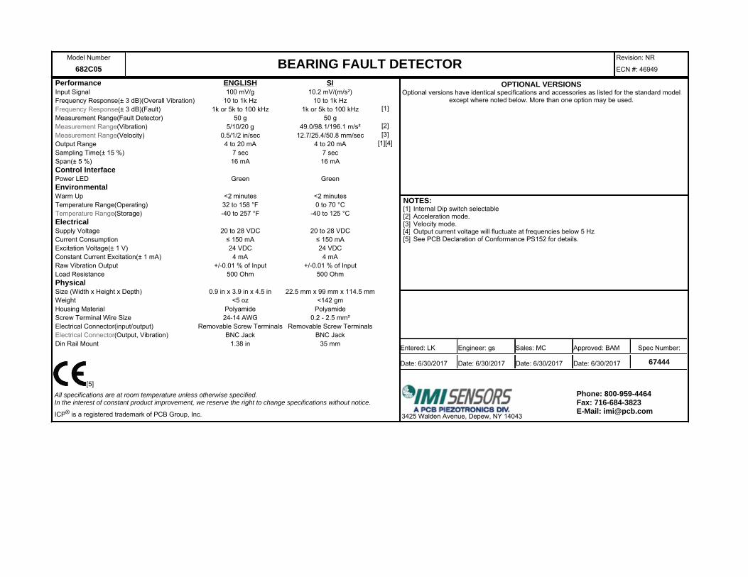
682C05 BEARING FAULT DETECTOR Revision: NR
ECN #: 46949
[5]
Performance ENGLISH SIInput Signal 100 mV/g 10.2 mV/(m/s²)Frequency Response(± 3 dB)(Overall Vibration) 10 to 1k Hz 10 to 1k HzFrequency Response(± 3 dB)(Fault) 1k or 5k to 100 kHz 1k or 5k to 100 kHz [1]Measurement Range(Fault Detector) 50 g 50 gMeasurement Range(Vibration) 5/10/20 g 49.0/98.1/196.1 m/s² [2]Measurement Range(Velocity) 0.5/1/2 in/sec 12.7/25.4/50.8 mm/sec [3]Output Range 4 to 20 mA 4 to 20 mA [1][4]Sampling Time(± 15 %) 7 sec 7 secSpan(± 5 %) 16 mA 16 mAControl InterfacePower LED Green GreenEnvironmentalWarm Up <2 minutes <2 minutesTemperature Range(Operating) 32 to 158 °F 0 to 70 °CTemperature Range(Storage) -40 to 257 °F -40 to 125 °CElectricalSupply Voltage 20 to 28 VDC 20 to 28 VDCCurrent Consumption ≤ 150 mA ≤ 150 mAExcitation Voltage(± 1 V) 24 VDC 24 VDCConstant Current Excitation(± 1 mA) 4 mA 4 mARaw Vibration Output +/-0.01 % of Input +/-0.01 % of InputLoad Resistance 500 Ohm 500 OhmPhysicalSize (Width x Height x Depth) 0.9 in x 3.9 in x 4.5 in 22.5 mm x 99 mm x 114.5 mmWeight <5 oz <142 gmHousing Material Polyamide PolyamideScrew Terminal Wire Size 24-14 AWG 0.2 - 2.5 mm²Electrical Connector(input/output) Removable Screw Terminals Removable Screw TerminalsElectrical Connector(Output, Vibration) BNC Jack BNC JackDin Rail Mount 1.38 in 35 mm
All specifications are at room temperature unless otherwise specified.In the interest of constant product improvement, we reserve the right to change specifications without notice.
ICP® is a registered trademark of PCB Group, Inc.
OPTIONAL VERSIONSOptional versions have identical specifications and accessories as listed for the standard model
except where noted below. More than one option may be used.
NOTES:[1] Internal Dip switch selectable[2] Acceleration mode.[3] Velocity mode.[4] Output current voltage will fluctuate at frequencies below 5 Hz.[5] See PCB Declaration of Conformance PS152 for details.
Entered: LK Engineer: gs Sales: MC Approved: BAM Spec Number:
Date: 6/30/2017 Date: 6/30/2017 Date: 6/30/2017 Date: 6/30/2017 67444
3425 Walden Avenue, Depew, NY 14043
Phone: 800-959-4464Fax: 716-684-3823E-Mail: [email protected]

![A New Bearing Fault Diagnosis Method based on Fine-to ...eprints.lincoln.ac.uk/34719/1/A New Bearing Fault Diagnosis Method... · system [1]–[3]. Hence, in recent decades, fault](https://img.dokumen.tips/doc/110x75/60138f4565d089085f7d7b04/a-new-bearing-fault-diagnosis-method-based-on-fine-to-new-bearing-fault-diagnosis.jpg)