Embed Size (px)
Citation preview

Model 62 EngineOperator Guide
United StatesDepartment ofAgriculture
Forest ServicePacific SouthwestRegion
VallejoCalifornia
January 2004
FOREST SERVICE
DEP A R T MENT OF AGRICUL T U R
E

The Material in this guide was prepared by members of the Pacific Southwest Region (R-5) Fire Equipment CommitteeMichael Madden, Chairperson; Phil Shafer, Bob Prather, Steve Mclaurin, Linda Keydeniers, and Michele Tanzi; TechnicalWriters/Editors; and San Dimas Technology and Development Center.
° ° ° ° ° ° ° ° ° ° ° ° °
DEDICATIONThis Model 62 Operator’s Guide is dedicated to the past Region 5 Mobile Fire EquipmentSubcommittee Chair, Lonnie Briggs. Lonnie’s commitment, sacrifice, and leadership to the Region 5fire engine development program has piloted R5 engine development into the 21st century. Thankyou, Lonnie for your support.
Information contained in this document has been developed for the guidance of employees of the Forest Service, United States Department ofAgriculture (USDA), its contractors, and cooperating Federal and State agencies. The USDA Forest Service assumes no responsibility for theinterpretation or use of this information by other than its own employees. The use of trade, firm, or corporation names is for the information andconvenience of the reader. Such use does not constitute and official evalution, conclusion, recommendation, endorsement, or approval of anyproduct or service to the exclusion of others that may be suitable.
The U.S. Department of Agriculture (USDA) prohibits discrimination in all its programs and activities on the basis of race, color, national origin, sex,religion, age, disability, political beliefs, sexual orientation, or marital or family status. (Not all prohibited bases apply to all programs.) Persons withdisabilities who require alternative means for communication of program information (Braille, large print, audiotape, etc.) should contact USDA’sTARGET Center at (202)720-2600 (voice and TDD).
To file a complaint of discrimination, write USDA, Director, Office of Civil Rights, Room 326-W, Whitten Building, 1400 Independence Avenue, SW,Washington, D.C. 20250-9410 or call (202)720–5964 (voice and TDD). USDA is an equal opportunity provider and employer.

TABLE OF CONTENTS
Introduction ...........................................................................................................................................................1
Model 62 Specifications ....................................................................................................................................... 6
Driver Qualifications and Responsibilities ...........................................................................................................13
Model 62 Operation .............................................................................................................................................15
Pump Operation ..................................................................................................................................................29
Foam Proportioning System ...............................................................................................................................42
Draining Instructions ...........................................................................................................................................51
Model 62 Maintenance ....................................................................................................................................... 51
Troubleshooting and Problem Solving ................................................................................................................ 57
Equipment Lists .................................................................................................................................................. 70
Appendix - Metric Equivalents .............................................................................................................................79

FIGURES
Figure 1—An International Model 62 engine ................................................................................................................. 2
Figure 2—Key to standard compartments. .................................................................................................................... 5
Figure 3—Rear view of Model 62 engine ..................................................................................................................... 35
Figure 4—Pressure relief valve panel .......................................................................................................................... 40
Figure 5—Applying torque to wheel lugnuts ................................................................................................................ 53
Figure 6—Tightening pattern for wheel lugnuts ........................................................................................................... 53
Figure 7—Air brake adjustment tolerances .................................................................................................................. 55
Figure 8—Typical clutch control linkage ....................................................................................................................... 55
TABLES
Table 1—Vehicle speed versus stopping distance ....................................................................................................... 27
Table 2—Standard USDA Forest Service engine valve numbers ................................................................................ 34
Table 3—Vehicle wheel problems ................................................................................................................................ 62
Table 4—Air brake problems ........................................................................................................................................ 64
Table 5—Vehicle will not move with standard transmission in gear ............................................................................. 64

Table 6—Cooling system problems ............................................................................................................................. 65
Table 7—Vehicle engine starting/charging problems .................................................................................................. 66
Table 8—Fuel system problems .................................................................................................................................. 67
Table 9—Pump does not prime when drafting ............................................................................................................ 69
Table 10—Model 62 fire hose and fittings ................................................................................................................... 70
Table 11—Model 62 miscellaneous tools and equipment ........................................................................................... 74
Table 12—Model 62 fireline handtools ........................................................................................................................ 76

1
INTRODUCTIONThis Model 62 Engine Operator’s Guide provides a reference for the chassis-cab and the power-take-off (pto) centrifugalpump unit:
• Applicable specifications
• Field maintenance
• Operating tips
• Troubleshooting and problem solving.
This guide is intended to be an orientation text for Model 62 crewmembers. You will not find all the answers to all yourquestions in this guide. More detailed information can be found in the manuals, booklets, and leaflets that come with thevarious Model 62 engine components, and in the U.S. Department of Agriculture (USDA) Forest Service handbooks andguides. Be sure to consult this guide and the Engine Operation and Maintenance Manual (EOMM) that is supplied byInternational with each vehicle.
Engines, used by the USDA Forest Service to deliver water during wildfire suppression efforts are called upon to operateon mountain roads and in off-road assignments along firelines. They are designed to operate under rough conditions withabnormally high physical stress and vibration.

2
Figure 1—An International Model 62 engine.

3
Model 62 EngineThe International Model 62 engine comes as a four-door 5-person cab. It consists of a transmission pto, a centrifugalpump, two live-hose reels, a pump operator’s control panel, and a 500-gallon tank built into a body with hose andaccessory storage compartments. Additionally, the engine has a dual-battery system, rear deck steps, a ladder, a redwarning light system, a siren, and an air horn. (Metric equivalents of the English units are provided in the appendix.)
The gross vehicle weight rating (GVWR) for the chassis-cab is 33,000 pounds. The 500-gallon baffled water tank mountedon the chassis-cab is constructed of polypropylene. The water tank contains two-20 gallon foam tanks. The tank isplumbed to a pto-driven, two-stage, liquid-primed, centrifugal pump.

4
Model 62 LayoutThe Model 62 compartment configuration is shown in figure 2.Vehicle controls are located in the cab, and pump controls arelocated on an operator’s panel at the rear of the engine.
The 12 compartments provide approximately 131 cubic feet ofstorage space. Two dust-resistant compartments with hinged doorsare located on each side of the engine to accommodate a fullcomplement of crew handtools, appliances, hose fittings, and soon. Two additional compartments are accessible from the top. Inaddition to the rear hose storage compartment, the hose storagearea on top of the engine has adequate space for 1-inch, 1 1/2-inch, and (optional) 2 1/2-inch standard fire hose. An additionalcompartment for storage of three lengths of 4-inch draft hose isprovided in the hose storage area on top of the engine (draft hosemust not exceed an overall length of 98 inches). The two live-hosereels along the sides and at the rear of the engine are designed tocarry 250 feet of 3/4-inch high-pressure hose.
COMPARTMENT
A—Personal/misc. storageB—Fittings/turnouts/first aidC—Misc.D—Misc.E—Personal/misc.F—Hand tools/chainsawG—Misc.H—Spare SCBA air bottlesI—Misc.J—Hose/portable pump/personalK—HoseL—Draft Hose

5
Figure 2—Key to standard compartments.
I
E - Under top lid
F
G
H
KL
J
A - Under top lid
B
CD

6
MODEL 62 SPECIFICATIONSSpecification sheets for the Model 62 are shown on the following pages. If you have a Model 62 engine assigned to yourcrew, find the specification sheet with your particular USDA Forest Service vehicle number on it. Mark all other enginespecification sheets “NOT APPLICABLE-FOR INFORMATION ONLY” to avoid any confusion. Note any modifications oradditions to the assigned Model 62 on the applicable specification sheet.

7
Model 62 Engine Specifications—(4 X 2), 6 speed w/split. Applicable to the following Forest Service vehicles: FS6476, 6232, 6239, 6251, 6244, 6246, 6470, 6242, 6010, 6236, 6233, 6235, 6240, 6243, 6245, and 6234.
Chassis mfgr: NAVISTAR INTERNATIONAL....Body contractor: BOISE MOBILE EQUIPMENT....Model: 4900....Year: 1997/98 .... Drive: 4 by 2....GVWR: 33,000 pounds....Front axle rating: 12,000 pounds....Rear axle rating: 21,000 pounds....Rear axle type: Spicer....Wheelbase: 170 inches.... Cab to axle: 55 inches....Overall length: 228 inches.... Width: 115 inches.... Height: 112 inches.... Minimum ground clearance: 9 1/2 inchesTurning radius: 50 feet 2 inches
Engine mfgr: International.... Model: DT-466E.... Bore and stroke: 4.3 by 5.35 inches.... Cu. in: 466Comp.ratio: 16.2:1....Net hp: 250....Net torque: 660.... Peak torque rpm: 1,450.... Peak torque rpm: 1,450....Max rpm: 2,300.... Crankcase capacity: 28 quarts.... Oil filters: P550367.... Air filter: 476741C1.... Battery: 12VGroup 31.... No: 3.... CCA: 650....Belts:.... Alternator: Delco-Remy America, 130 amp.... Load manager equipped:(Yes or No) Yes
Tire size: 11R22.5 14 Ply.... Load range: G.... Wheel type: Steel 22.5 by 8.25 10 stud.... Lugnut torque: 750 - 900 footpounds
Fuel capacity: 75 gallons.... Coolant filter: .... Fuel filter, primary:.... Secondary:
Transmission Mfgr: Fuller.... Model: FS-8206A.... Ratios: 1st:.... 2nd:.... 3rd:.... 4th: 1.89.... 5th:.... 6th:.... Rev:
Differential mfgr:... Model:
PTO Mfgr: Chelsea.... Model: 680XTDUXA5XV
Pump Mfgr: Darley & Company.... Model: JMP 500.... Type: Two-stage centrifugalMax operating engine RPM: 2,300.... Max operating pressure: 400 psi

8
Model 62 Engine Specifications—(4 X 4), 6 speed w/split. Applicable to the following Forest Service vehicles:FS 6256, 6043, 6261, and 6271.
Chassis mfgr: NAVISTAR INTERNATIONAL....Body contractor: BOISE MOBILE EQUIPMENT....Model: 4900....Year: 1997/98 .... Drive: 4 by 4....GVWR: 33,000 pounds....Front axle rating: 12,000 pounds....Rear axle rating: 21,000 pounds....Rear axle type: J2105SN....Wheelbase: 170 inches.... Cab to axle: 55 inches....Overall length: 290 inches.... Width: 115 inches.... Height: 112 inches.... Minimum ground clearance: 9 1/4 inchesTurning radius:
Engine mfgr: International.... Model: DT-466E.... Bore and stroke: 4.3 by 5.35 inches.... Cu. in: 466Comp.ratio: 16.2:1....Net hp: 250....Net torque: 660.... Peak torque rpm: 1,450.... Peak torque rpm: 1,450....Max rpm: 2,300.... Crankcase capacity: 28 quarts.... Oil filters: P550367.... Air filter: 476741C1.... Battery: 12V Group31.... No: 3.... CCA: 650....Belts:.... Alternator: Delco-Remy America, 130 amp....Load manager equipped: (Yes orNo) Yes
Tire size: 11R22.5 14 Ply.... Load range: G.... Wheel type: Steel 22.5 by 8.25 10 stud.... Lugnut torque: 750 - 900 footpounds
Fuel capacity: 75 gallons.... Coolant filter: .... Fuel filter, primary:.... Secondary:
Transmission Mfgr: Fuller.... Model: FS-8206A.... Ratios: 1st:.... 2nd:.... 3rd:.... 4th: 1.89.... 5th:.... 6th:.... Rev:
Differential mfgr:Tractech... Model: Npspin
PTO Mfgr: Chelsea.... Model: 440XXDUX-P5R
Pump Mfgr: Darley & Company.... Model: JMP 500.... Type: Two-stage centrifugalMax operating engine RPM: 2,300.... Max operating pressure: 400 psi

9
Model 62 Engine Specifications—(4 X 2), 6 speed w/split. Applicable to the following Forest Service vehicles:FS 6425, 6398, 6349, 6424, 6426, 6429, 6306, and 6307.
Chassis mfgr: NAVISTAR INTERNATIONAL....Body contractor: BOISE MOBILE EQUIPMENT....Model: 4900....Year: 1999 .... Drive: 4 by 2....GVWR: 33,000 pounds....Front axle rating: 12,000 pounds....Rear axle rating: 21,000 pounds....Rear axle type: Spicer....Wheelbase: 170 inches.... Cab to axle: 55 inches....Overall length: 287 inches.... Width: 115 inches.... Height: 115 inches.... Minimum ground clearance: 9 1/2 inchesTurning radius: 50 feet 2 inches
Engine mfgr: International.... Model: DT-466E.... Bore and stroke: 4.3 by 5.35 inches.... Cu. in: 466Comp.ratio: 16.2:1....Net hp: 250....Net torque: 660.... Peak torque rpm: 1,450.... Peak torque rpm: 1,450....Max rpm: 2,300.... Crankcase capacity: 28 quarts.... Oil filters: P550367.... Air filter: 476741C1.... Battery: 12VGroup 31.... No: 3.... CCA: 650....Belts:.... Alternator: Delco-Remy America, 130 amp....Load manager equipped:(Yes or No) Yes
Tire size: 11R22.5 14 Ply.... Load range: G.... Wheel type: Steel 22.5 by 8.25 10 stud.... Lugnut torque: 750 - 900 footpounds
Fuel capacity: 75 gallons.... Coolant filter: .... Fuel filter, primary:.... Secondary:
Transmission Mfgr: Fuller.... Model: FS-8206A.... Ratios: 1st:.... 2nd:.... 3rd:.... 4th: 1.89.... 5th:.... 6th:.... Rev:
Differential mfgr:... Model:....
PTO Mfgr:.... Model:
Pump Mfgr: Darley & Company.... Model: JMP 500.... Type: Two-stage centrifugalMax operating engine RPM: 2,300.... Max operating pressure: 400 psi

10
Model 62 Engine Specifications—(4 X 4), 6 speed w/split. Applicable to the following Forest Service vehicles:FS 6430.
Chassis mfgr: NAVISTAR INTERNATIONAL....Body contractor: BOISE MOBILE EQUIPMENT....Model: 4900....Year: 1999 .... Drive: 4 by 4....GVWR: 33,000 pounds....Front axle rating: 12,000 pounds....Rear axle rating: 21,000 pounds....Rear axle type: Spicer....Wheelbase: 170 inches.... Cab to axle: 55 inches....Overall length: 290 inches.... Width: 115 inches.... Height: 115 inches.... Minimum ground clearance: 9 1/4 inchesTurning radius: 50 feet 2 inches
Engine mfgr: International.... Model: DT-466E.... Bore and stroke: 4.3 by 5.35 inches.... Cu. in: 466Comp.ratio: 16.2:1....Net hp: 250....Net torque: 660.... Peak torque rpm: 1,450.... Peak torque rpm: 1,450....Max rpm: 2,300.... Crankcase capacity: 28 quarts.... Oil filters: P550367.... Air filter: 476741C1.... Battery: 12VGroup 31.... No: 3.... CCA: 650....Belts:.... Alternator: Delco-Remy America, 130 amp....Load manager equipped:(Yes or No) Yes
Tire size: 11R22.5 14 Ply.... Load range: G.... Wheel type: Steel 22.5 by 8.25 10 stud.... Lugnut torque: 750 - 900 footpounds
Fuel capacity: 75 gallons.... Coolant filter: .... Fuel filter, primary:.... Secondary:
Transmission Mfgr: Fuller.... Model: FS-8206A.... Ratios: 1st:.... 2nd:.... 3rd:.... 4th: 1.89.... 5th:.... 6th:.... Rev:
Differential mfgr:... Model:....
PTO Mfgr: Chelsea.... Model: 440XXDUX-P5R
Pump Mfgr: Darley & Company.... Model: JMP 500.... Type: Two-stage centrifugalMax operating engine RPM: 2,300.... Max operating pressure: 400 psi

11
Model 62 Engine Specifications—(4 X 2), 6 speed w/split. Applicable to the following Forest Service vehicles:FS 6518, 6519, 6577, 6484, 6499, 6514, 6501, 6503, 6517, and 6515.
Chassis mfgr: NAVISTAR INTERNATIONAL....Body contractor: BOISE MOBILE EQUIPMENT....Model: 4900....Year: 1999/2000 .... Drive: 4 by 2....GVWR: 33,000 pounds....Front axle rating: 12,000 pounds....Rear axle rating: 21,000 pounds....Rear axle type: Spicer....Wheelbase: 170 inches.... Cab to axle: 55 inches....Overall length: 287 inches.... Width: 115 inches.... Height: 115 inches.... Minimum ground clearance: 9 1/2 inchesTurning radius: 50 feet 2 inches
Engine mfgr: International.... Model: DT-466E.... Bore and stroke: 4.3 by 5.35 inches.... Cu. in: 466Comp.ratio: 16.2:1....Net hp: 250....Net torque: 660.... Peak torque rpm: 1,450.... Peak torque rpm: 1,450....Max rpm: 2,300.... Crankcase capacity: 28 quarts.... Oil filters: P550367.... Air filter: 476741C1.... Battery: 12VGroup 31.... No: 3.... CCA: 650....Belts:.... Alternator: Delco-Remy America, 130 amp....Load manager equipped:(Yes or No) Yes
Tire size: 11R22.5 14 Ply.... Load range: G.... Wheel type: Steel 22.5 by 8.25 10 stud.... Lugnut torque: 750 - 900 footpounds
Fuel capacity: 75 gallons.... Coolant filter: .... Fuel filter, primary:.... Secondary:
Transmission Mfgr: Fuller.... Model: FS-8206A.... Ratios: 1st:.... 2nd:.... 3rd:.... 4th: 1.89.... 5th:.... 6th:.... Rev:
Differential mfgr:... Model:....
PTO Mfgr: .... Model:
Pump Mfgr: Darley & Company.... Model: JMP 500.... Type: Two-stage centrifugalMax operating engine RPM: 2,300.... Max operating pressure: 400 psi

12
Model 62 Engine Specifications—(4 X 4), 6 speed w/split. Applicable to the following Forest Service vehicles: FS6520, 6533, 6521, 6522, 6502, 6504, and 6532.
Chassis mfgr: NAVISTAR INTERNATIONAL....Body contractor: BOISE MOBILE EQUIPMENT....Model: 4900....Year: 2000 .... Drive: 4 by 4....GVWR: 33,000 pounds....Front axle rating: 12,000 pounds....Rear axle rating: 21,000 pounds....Rear axle type: Spicer....Wheelbase: 170 inches.... Cab to axle: 55 inches....Overall length: 290 inches.... Width: 115 inches.... Height: 115 inches.... Minimum ground clearance: 9 1/4 inchesTurning radius: 50 feet 2 inches
Engine mfgr: International.... Model: DT-466E.... Bore and stroke: 4.3 by 5.35 inches.... Cu. in: 466Comp.ratio: 16.2:1....Net hp: 250....Net torque: 660.... Peak torque rpm: 1,450.... Peak torque rpm: 1,450....Max rpm: 2,300.... Crankcase capacity: 28 quarts.... Oil filters: P550367.... Air filter: 476741C1.... Battery: 12VGroup 31.... No: 3.... CCA: 650....Belts:.... Alternator: Delco-Remy America, 130 amp....Load manager equipped:(Yes or No) Yes
Tire size: 11R22.5 14 Ply.... Load range: G.... Wheel type: Steel 22.5 by 8.25 10 stud.... Lugnut torque: 750 - 900 footpounds
Fuel capacity: 75 gallons.... Coolant filter: .... Fuel filter, primary:.... Secondary:
Transmission Mfgr: Fuller.... Model: FS-8206A.... Ratios: 1st:.... 2nd:.... 3rd:.... 4th: 1.89.... 5th:.... 6th:.... Rev:
Differential mfgr:... Model:....
PTO Mfgr: Chelsea.... Model: 440XXDUX-P5R
Pump Mfgr: Darley & Company.... Model: JMP 500.... Type: Two-stage centrifugalMax operating engine RPM: 2,300.... Max operating pressure: 400 psi
13
DRIVER QUALIFICATIONS AND RESPONSIBILITIESAll personnel who operate Government owned or leased motor vehicles must meet qualifications stated in FSH 7109.19as well as any applicable U. S. Department of Transportation regulations. The Model 62 has a gross vehicle weight rating(GVWR) that exceeds 26,001 pounds and therefore a California class “B” commercial license, or the equivalent, isrequired.
To avoid accidents, modern day conditions necessitate that drivers be responsible, mature, and skillful. Good drivers aredeveloped, not born. They attain the required attitudes and skills through training programs that include both classroomand on-the-road instruction. The goal of the instruction should be to develop proper driving habits and attitudes, includinglearning to exercise good judgment and restraint. Important factors that govern skillful driving include:
• Personality and attitude of the driver.
• Satisfactory completion of a driver training and testing program.
• Limitations and condition of the vehicle.
• Physical features and terrain of the roadway.
• Weather and lighting conditions.
• Attitude, behavior, and reactions of drivers of nearby vehicles.
Despite all mechanical improvements and automotive safety devices, the driver is still the key to traffic safety. Driversmust keep in good physical condition, have sound driving skills and habits, and develop and maintain proper attitudes.The attributes of a good driver are directly related to attitude, knowledge, judgments, habits, physical fitness, mentalfitness, and skills.

14
AttitudeA good attitude is possibly the most important requirement of a good driver. A driver’s attitude is reflected in their mentalregard for self, others, the vehicle, and surrounding conditions. A driver with a poor attitude usually has an excuse for anyadverse occurrence, i.e., the other person was at fault, the roadway was bad, the intersection was blind, and so on.
Unfortunately, the driver who is a nice person (a perfect gentleperson), until they are behind the wheel, is not rare. Thereis always the danger that: upon climbing into the “rig” and acquiring the authority of red lights, siren, and several tons ofvehicle; the driver feels suddenly like a “big shot,” with no need to consider courtesy or safety.
Driving RegulationsWhen operating a vehicle follow the applicable driving standards and requirements in FSH 6709.11, Forest ServiceHealth and Safety Handbook, and FSH 7109.19, Fleet Equipment Managers Handbook.
Forest Service Handbook, 7109.19 – Fleet Equipment Managers Handbook, chapter 66, reads as follows:
“66 – Hours of Service. USDA Forest Service employees who drive motor vehicles or specialized equipment are notrequired to maintain a record of duty status or a driver’s log as required in Title 49, Code of Federal Regulations, Section395.8 (49 CFR 395.8).”

15
MODEL 62 OPERATIONPreparing to DriveAdjust the driver’s seat so all controls are easy to operate. Check to see that nothing is on the cab floor that might rollunder the accelerator or brake pedal once the vehicle is underway. Adjust all mirrors for maximum visibility to the rear.Fasten seatbelts before starting the vehicle engine.
NOTE: The DT-466E engine is equipped with an electronic control module (ecm). The ecm is the electronicbrain controlling the engine functions including throttle position. When the accelerator or rear throttleis activated an electronic signal is sent to the ecm. There is no solid connection between the pedal orrear throttle control.
Starting the EngineNever start a diesel engine–equipped with a turbocharger–at high-throttle rpm. There is insufficient lubrication at theturbocharger when starting the engine, and the engine needs to run at an idle until the lubricant reaches the turbocharger.The turbocharger, at peak performance, is operating at about 120,000 rpm and the bearings ride on a film of oil; withoutlubrication premature turbocharger failure can occur.
Within seconds after starting, the engine oil pressure should exceed 20-psi minimum. If the oil pressure does not reachthe minimum limit stop the engine, locate and correct the problem. After the engine has reach an operating temperaturethe oil pressure should be at 50-psi minimum.
Prestarting checks. Consult the Engine Operation and Maintenance Manual (EOMM) (section 5, page 1) provided by themanufacturer before starting the engine
NOTE: Follow all procedures outlined in the California Department of Motor Vehicle Pretrip inspection guide,found in the DMV Commercial Drivers Handbook, before operating any commercial vehicle.
16
Normal Starting Procedure–Ambient Temperature Above 10 °F
• Ensure that the parking brake is applied.
• Depress the clutch pedal. Hold the clutch pedal to the floor while starting the engine.
• Leave the accelerator at the idle position.
• Engage the starter and crank the engine.
CAUTION: If the engine does not start after 30 seconds of cranking, allow the starter motor to cool for 2minutes before trying again. If after three attempts the engine does not start, investigate anddetermine why the engine is not starting. Excessive cranking may damage the starter.
CAUTION: Try to limit engine operation at an idle. Excessive idling will reduce fuel economy. The lowercombustion temperatures associated with extended periods of idling can cause carbon buildupon the injectors, piston rings, and valves and result in the dilution of the lubricating oil byunburned fuel. If the particular application requires that the engine idle for long periods of time,the duty cycle must be considered ‘severe service,’ which requires more frequent maintenanceintervals. Reduce the oil change interval to one-half of that required for normal service.
NOTE: For more information regarding the affects of extended low idle refer to the EOMM (section 5, page 11).
Cold Weather Starting Procedure–Ambient Temperature Below 10 °FRefer to the EOMM (section 5, page 6).

17
CAUTION: No form of starting fluid should be used except through a premeasured dosage system.
Restarting After Running Out of FuelRefer to the EOMM (section 7, page 20).
Restarting an engine that has run out of fuel is difficult because fuel is exhausted from the fuel tank, air enters fuelingsystem, and insufficient fuel is present to sustain engine firing. The fuel system must be refilled with fuel and the fuel linespurged of air before the system can provide adequate fuel to the injectors to start the engine.
WARNING: If you are unfamiliar with the procedure outlined in section 7, page 20 of the EOMM, do notattempt it. Personal injury or engine damage could occur if not done properly. Contact your fleetmechanic for assistance.
WARNING: Fuel sprayed or leaked is an obvious fire hazard. Never attempt to purge a hot engine, escapingfuel could leak on the exhaust manifold creating a potential for fire. Keep all flame-burningtobacco products and sparks away from the vehicle when servicing the fuel system.
WARNING: Injector supply lines contain high fuel pressure. The pressure of the fuel is sufficient to penetratethe skin and cause serious injury. Wear gloves and eye protection when working with high-pressure fuel lines.
Emergency Starting With Jumper CablesRefer to the EOMM (section 5, page 9).
Treat all batteries carefully when using jumper cables. Be careful not to cause sparks.

18
WARNING: Use only this procedure. Any other procedure could result in serious personal injury or propertydamage because batteries normally produce explosive gases; or they could damage the chargingsystem of the disabled vehicle. Ensure that the starting systems of both vehicles have the samevoltage outputs. A 12-volt starter can be damaged beyond repair if connected to a 24-volt powersupply, even when cranking loads are light.
• Ensure that the vehicles do not touch one another. Apply the parking brakes. Turn off the lights, heater, and allother electrical loads.
• Locate the positive terminal of the discharged battery.
• Attach an end of one jumper cable to the positive terminal of the booster battery and the opposite end of the cableto the positive terminal of the discharged battery.
• Attach one end of the other jumper cable to the negative terminal of the charged battery and the opposite end toa ground at least 12 inches from the discharged battery of the vehicle being started. The vehicle frame is usuallya good ground.
WARNING: Do not attach the other end to the negative battery terminal because a spark could occur andcause an explosion in the gases normally present around the battery.
• Ensure that the clamps from one cable do not touch the clamps on the other cable. Do not lean over the batterieswhen making the connections.
• Ensure that everyone is standing away from the vehicles. Start the engine of the vehicle with the booster batteries.Wait a few minutes and then attempt to start the fire truck engine with the newly charged batteries.

19
CAUTION: If the engine does not start after 30 seconds of cranking, allow the starter motor to cool for 2minutes before trying again. If after three attempts the engine does not start investigate, anddetermine the cause. Excessive cranking may damage the starter.
Operating the Engine
CAUTION: Do not operate the engine at full throttle below peak torque engine rpm for durations longer than1 minute (peak torque engine rpm for the DT-466E is 1,500 rpm). Prolonged engine lugging of thisnature will damage the engine. If this occurs when climbing a hill, decrease acceleration until younotice a reduction in engine rpm, then depress accelerator just enough to maintain rpm. It may benecessary to shift to a lower gear that maintains rpm at or above the peak torque engine rpm.
• Monitor the oil pressure and coolant temperature gauges frequently. If the gauges indicate readings not in thenormal operating range, stop the vehicle as soon as possible, shut off the engine, and check the appropriate fluidlevels.
• If an overheating condition occurs, reduce the power output of the engine by releasing the throttle pressure orshifting the transmission into a lower gear, or both, until the temperature returns to the normal operating range.
CAUTION: Continuous operation with low-coolant temperature below 160 °F, or high-coolant temperatureabove 212 °F, can damage the engine.
Most failures give an early warning. Look and listen for changes in performance, sound, or engine appearance, whichindicate a need for service or engine repair. Some changes to look for are as follows:
• Engine misfires.
• Loss of power.

20
• Sudden changes in engine operating temperature or oil pressure.
• Excessive smoke.
• Fuel, oil, or coolant leaks.
• Vibration.
• Increase in oil consumption.
• Increase in fuel consumption.
IdlingIf engine operations include extended periods of idling, idle speed should be set above 1,400 rpm if possible. Dieselengine efficiency is improved when the cylinder temperature remains high.
NOTE: After 5 minutes of idle time, and the intake air temperature is below 32 °F, the cold ambientprotection system (cap) slowly ramps up the engine idle speed to 1,400 rpm on engines equippedwith manual transmissions. The engine speed will increase or decrease to an rpm that maintains acoolant temperature of 160 °F (refer to EOMM section 5, page 11).
NOTE: Batteries may not sufficiently charge during extended periods of idling below 1,400 rpm.
Engine Shut-Down Procedures
• Allow the engine to idle 3 to 5 minutes after a full-load operation before shutting it off. This allows the engine andthe turbocharger to cool gradually and uniformly. Following this procedure will extend the life of the engine andturbocharger.

21
• Turn the ignition key switch to the “off” position.
CAUTION: Do not allow the engine to idle for more than 10 minutes under ordinary circumstances.
DrivingStart the vehicle in motion by using the highest gear that enables the engine to move the load easily without slipping theclutch. Accelerate smoothly and evenly to the engine-rated speed.
When starting on a grade with the clutch engaged, the rpms will drop off significantly; when an engine’s rpms fall off, donot disengage the clutch and try to increase the rpms. Doing so may damage the driveline components. After the initialdrop in speed, the engine recovers and accelerates in a normal manor.
To avoid lugging conditions, engine speed should not drop below peak torque (1,500 rpm for the DT-466E) when pullingat full throttle. When approaching a hill, depress the accelerator smoothly to start up the grade at full power. Shift down asneeded to maintain appropriate vehicle speed.
Downhill OperationPrevent over speeding of the engine when going down long and steep grades. The governor has no control over theengine speed when it is being pushed by the loaded vehicle. Operate in a gear that permits an engine speed not toexceed the maximum rpm (2,500 for the DT-466E). Operating the engine beyond 2,500 rpm can cause severe damageto the engine.
Exhaust BrakeNOTE: An exhaust brake will not operate with the cruise control switch in the “on” position.
The Model 62 engines are equipped with an exhaust braking system that assists–but does not replace–the primary servicebrake system. An “on-off” instrument panel switch, in combination with the accelerator and clutch pedal switches, allows theoperator to make maximum use of the exhaust brake in mountain driving as well as in high-speed highway driving.
22
• Starting the engine. Before starting the engine, ensure that the exhaust brake switch is in the “off” position. Do not turnon the exhaust brake until the engine has reached normal operating temperatures.
• Driving downhill. When approaching a steep grade, ensure that the exhaust brake switch is in the “on” position. Theexhaust brake will actuate as soon as your foot is removed from the accelerator pedal. While going down the grade,use a gear low enough to allow a safe descent of the grade with a minimum application of the service brakes.
CAUTION: The exhaust brake works best when the driver shifts gears to keep the engine running at an increasedrpm. Do not exceed the maximum allowable engine rpm (2,500 for the DT-466E) while driving downa steep grade. Doing so will result in damage to the engine. Apply the service brakes to reduce theengine rpm or make a slower decent by using a lower gear.
• Shutting off the engine. Ensure that the exhaust brake is turned “off” before shutting off the engine.
WARNING: Before descending a hill or steep grade always select the proper gear. If the transmission istaken out of gear while descending it may not be possible to select another gear because of themaximum rpm being governed.
WARNING: DRIVING ON SNOW AND ICE–The exhaust brake is not recommended for use on slippery or low-traction road surfaces. Under these conditions a loss of vehicle control could occur.
TransmissionsThe vehicle is equipped with a six-speed manual transmission with a two-speed rear end. The correct use of the gearsincreases engine performance, provides longer engine and transmission life, and enhances safe driving. The clutchpedal should be fully depressed prior to selecting a gear.
WARNING: Allowing the vehicle to coast in neutral is not only unsafe it is illegal. This practice results insevere transmission damage; thus, engine braking would not be available.

23
Two-Speed Rear AxleA two-speed axle allows the vehicle operator to select low range (button “down”) for good starting torque and pullingpower. By selecting high range (button “up”), the axle is shifted to a gear ratio that allows greater road speed andeconomy. In addition, high or low range can be used where desired for gradeability or economy to provide additional“steps” between transmission gear ratios.
A two-speed axle can be used as a ratio extender when split shifting is not necessary. For low-end use, shift the axle intolow range to start out, and shift to high when the extra torque is no longer needed. To use the two-speed as a high-endratio extender, stay in low range for normal up-shifts and only shift to axel high range for greater speed on the freeways.Due to the extra torque associated with diesel engines it is not always necessary (and should be discouraged) to splitshift the rear end every time the transmission is shifted.
Two-Speed Axle ShiftingAxle up-shift from low to high range. Pull the axle shift button “up” and release the accelerator pedal. The axle shifts andyou can resume acceleration. In lower gears the use of the clutch along with releasing the accelerator pedal will smoothout any abrupt shifting that may cause the truck to jerk.
Axle down-shifting from high to low range. Depress the button and release the accelerator. Depress the acceleratorquickly. A shift from high to low range requires that the ring gear speed be one-third more than the wheel speed.
WARNING: Never shift a two-speed axle on a downgrade.
If the vehicle increases in speed faster than the engine rpm, the rear will not shift and the vehicle will not be runningagainst the engine’s compression.
Split up-shift. An axle down-shift with a transmission up-shift is called a split up-shift. Depress the clutch and shift thetransmission up to the next higher gear. Depress the button, release the clutch, and depress the accelerator.

24
Split down-shift. An axle up-shift with a transmission down-shift is called a split down-shift. Lift the button and depressthe clutch. Shift the transmission down to the next lower gear and release the clutch.
Four-Battery SystemThe Model 62 engine has a four-battery system and a battery selector switch with four positions. The purpose of the four-battery system and battery selector switch is to ensure that there is sufficient electrical reserve to start the vehicle engineat any time. It is the responsibility of the operator to ensure that the system is used properly and that all batteries aremaintained in a fully charged condition. The batteries are arranged in groups of two. Each pair of batteries is connectedin parallel to increase available amperage and maintain 12 volts.
Battery Selector Switch Positions
• Position 1–Connects battery group 1 to the vehicle electrical system. In this position battery group 2 is completelydisconnected from the vehicle, it neither charges nor discharges.
• Position 2–Connects battery group 2 to the vehicle electrical system. In this position battery group 1 is completelydisconnected from the vehicle, it neither charges nor discharges.
• Position BOTH–Connects, in parallel, both battery group 1 and battery group 2 to the vehicle electrical system. Inthis position both battery groups are either charged or discharged at the same time, but not necessarily at thesame rate.
• Position OFF–Disconnects both battery group 1 and battery group 2 from the vehicle electrical system.
NOTE: The DT-466E engine is equipped with an electronic control module (ecm). This is the electronic brainscontrolling the engine functions including throttle position. Electrical power for the ecm comesdirectly from the first bank of batteries. It is crucial that the first set of batteries remain charged at alltime.

25
CAUTION: Never move the battery selector switch to the “off” position while the engine is running. If will damagethe charging system.
For those engines equipped with a four-position switch (off, 1, 2, and both) the “both” position should be selected whendriving the Model 62 engine to an incident to ensure that both batteries are fully charged upon arrival. The switch shouldbe moved to position 1 or 2 upon arrival at the incident. This prevents draining both batteries and assures one fullycharged battery to start and run the vehicle at any time. It is the responsibility of the operator to ensure that the switch isnot moved from the selected position.
In the event that the vehicle is caught with two low battery groups, the “both” position may provide enough energy to startthe engine. Then turn the switch to position 1 or position 2 to quick-charge one battery group. Do not leave the vehiclewith the battery selector switch in the “both” position because:
• Any electrical drain in the vehicle will discharge both batteries.
• If one battery group is dead it may discharge the other battery group.
The “off” position should be used when the vehicle is parked and the engine is turned off. This prevents battery drain incase equipment has been left on, or if a short circuit exists. It may also reduce the likelihood of vandalism, damage, theft,or unauthorized use of the vehicle.
SteeringExcept when shifting gears keep both hands on the steering wheel, preferably in the 9 and 3 o’clock positions. This helpsminimize the possibility of losing control if there are potholes or ruts in the road. Avoid shifting gears while turning thevehicle.

26
When backing the vehicle, have a crewmember provide hand signals to the driver. If a helper is not available, get out andcheck behind the vehicle before backing.
BrakingAir BrakesFanning of air brakes. The repeated rapid application and release of the brake pedal during a stop should be avoided. Itprovides poor brake performance. Fanning decreases air pressure in the brake chambers. The reservoir air volume maybe reduced faster than the air compressor can compensate for the loss.
Apply firm pressure to the brake pedal to slow the vehicle to the desired speed; then completely release the brakes toavoid excessive heat buildup. This procedure is known as “stabbing” the brakes. Use lower gears to hold the vehicle backto avoid using the brakes too much. As brakedrums heat, their efficiency declines until the drums are hot enough to beineffective in slowing or stopping the vehicle.
ABS Brakes OperationStopping DistanceMany factors determine the total stopping distance of the vehicle. The three most significant are:
• Perception/reaction time. The time it takes the driver to see and identify a problem and start braking.
• Brake lag. The time between brake pedal application and the brakes contacting the drum.
• Braking distance. The distance the vehicle travels once the brake is applied. Vehicle size and weight affect brakingdistance. The Model 62 engine has a GVWR of 33,000 pounds. The average total stopping distance is more thanfor a passenger car.

27
The effect of vehicle speed on these three factors (and on the total stopping distance) can be seen in table 1. When thespeed is doubled, the average perception/reaction and brake lag distances are approximately doubled, while the averageeffective braking distance is increased four times.
Table 1—Vehicle speed vs. stopping distance
Vehicle Speed Average Perception/ Average Brake Average Effective Average TotalMiles per Hour Feet per Second Reaction Distance Lag Distance Braking Distance Stopping Distance
30 44 66 18 45 120
60 88 135 35 180 360
Parking BrakeThe parking brake is not designed to help bring the engine to a stop. Its purpose is to prevent the vehicle from rollingwhen parked. Chock blocks are required when the vehicle is parked.
WARNING: Stop the vehicle immediately if the air gauge indicates pressures below 60 psi, or when the audiblewarning buzzer is actuated.
Emergency ResponsesUSDA Forest Service policy requires that employees comply with all State and local regulations. Over 30 sections of theCalifornia Vehicle Code (CVC) have material applicable to emergency vehicles.
A Code 2 response means that the vehicle proceeds directly, when dispatched, to the scene of the emergency. The driverobeys all traffic laws and rules of the road.
+ + =

28
A Code 3 response means that the vehicle proceeds under red light and siren. During a code 3 operation, section 21055of the CVC exempts drivers of authorized emergency vehicles from complying with certain provisions of other sections ofthe CVC. However, section 21055:
• Does not relieve the driver of the responsibility of driving with due regard for the safety of all aboard the emergencyvehicle and all those within other vehicles or pedestrians using the roadways (section 21056).
• Does not grant any exemptions to an emergency vehicle when the red light and siren are not in use (as whenreturning to the station after emergency duty, and so on).
• Does not protect the driver from the consequences of arbitrary exercise of emergency response privileges.
Other points to be kept in mind include:
• Never start out on an emergency response without knowing where you are going.
• Motorists and pedestrians must be afforded the opportunity to yield the right-of-way to an emergency vehicle,especially at intersections. Emergency vehicles do not have the right-of-way unless it is granted to them.
• Never travel through an intersection at a speed greater than the emergency vehicle could be stopped if the vehicleright-of-way is violated.
• Be aware that a motorist, upon first hearing a siren, might stop just ahead of the emergency vehicle.
• Do not pass on the right unless this is the only recourse, and do so with extreme care.
• Keep near the center of the roadway so that oncoming traffic can see the approaching red lights.
29
• When more than one emergency vehicle is proceeding down the same roadway, be aware that motorists havingyielded to the first vehicle may pull out in front of the remaining emergency response vehicles.
• If caught in an urban, congested bumper-to-bumper situation and know of no feasible alternate routes, suspendcode 3 operations and proceed with the flow of traffic as best you can.
• When traveling on a freeway, turn off the siren and red lights and proceed with the flow of traffic.
• Do not continuously sound the siren at its highest pitch–fluctuate it throughout its tonal range.
• Use the air horn only when approaching intersections and then just two or three short blasts are sufficient.
PUMP OPERATIONSThe pump used on the Region 5 Model 62 engine is a W.S. Darley & Co. Champion, model JMP-500. This is a two-stagecentrifugal pump, adapted to operate with its impellers in series as a two-stage pump for higher pressures, or in parallelfor volume pumping. The pump is equipped with a positive-displacement priming pump powered by a 12-volt electricmotor. The majority of the hydraulic controls are on the operator’s panel at the rear of the engine.
The Region 5 Model 62 is equipped with three, 1 1/2-inch discharges. One on both the left and the right side of thevehicle and one mounted on the front bumper. There are two, 2 1/2-inch discharges and one 4-inch overboard suction atthe rear of the vehicle. There are live reels mounted on the right and left sides on the rear of the vehicle.
Air-Activated ValvesTo accommodate space requirements some mechanical valves on the Model 62 have been replaced with air-activatedvalves. The valves are the same; the means of opening and closing them has changed.
The switches for opening and closing these valves are located on the rear of the engine, centered just below the rearhose compartment. Traditional Region 5 engine valve numbers have been used with the function added in clear text.(See table 2.)

30
The following valves are air activated:Number/Function
1/Tank-to-Pump
2/Pump-to-Tank
4/Left- and right-hand live reels
13/Gravity drain tank
CAUTION: The gravity drain has no anti-siphon protection and is not to be used when filling from apressurized domestic water source.
To open any of these valves place the switch in the up (“open”) position. An air-escaping sound will be heard.
To close any of these valves place the switch in the down (“closed”) position. An air-escaping sound will be heard and airmay be felt lightly across the fingers at the switch location. Exercise all valves on a regular basis to ensure properoperation.
Hannay live reels do not have a brake per-say but are equipped with a friction brake that can be adjusted to a desiredpoint and left alone.
NOTE: Air-activated valves are either “open” or “closed.” There is no cracking open these valves.
The air pressure to activate these valves is supplied from the air compressor supplying the vehicle air-brake systemthrough a priority valve. The vehicle air-brake system has the highest priority. Once air pressure is established in thebrake system air becomes available to the valve air cylinders.

31
Should an air line on the valve air system fail, the priority valve would prevent air from escaping from the vehicle air brakesystem. Once this occurs all air-activated valves will more than likely fail to respond and remain in the position they werein when failure occurred. The valves can be manually activated by gaining access to them through the floor of the rearhose compartment or from under the vehicle.
Priming Pump OperationThe 12-volt priming pump is a positive-displacement pump run by an electric motor. To activate, open the appropriatevalves (tank-to-pump or overboard suction), close all discharge valves, and pull the primer handle (T-handle engravedHALE). The priming valve (was the USDA Forest Service valve #6) is opened automatically upon activation of thepriming pump. Activate the priming pump until a firm and constant pressure is displayed on the overboard-pressuregauge. Push the T-handle in and the priming pump will stop. Set the desired pressure and open the appropriate overboarddischarges or the pump-to-tank valve.
NOTE: If pressure drops significantly or near zero and water fails to discharge, close the discharge valvesand repeat the priming procedure. If flowing water to your tank through the pump-to-tank valve, withthe pump-to-tank valve open 100 percent, the pressure gauge may show very low pressure due to alack of restriction.
There is a fluid reservoir associated with the priming pump located behind a door just forward of the ladder at the rear ofthe vehicle. Ensure that the reservoir has the recommended fluid at all times. Current thought suggests a mixture ofwater and an environmentally friendly antifreeze. Refer to the section on maintenance of the priming pump in this guide.
Pump Instructions
• Keep dry-pumping operation to a minimum; never exceeding 30 seconds of dry operation.
• If the pump is run when dry, do not add water until the pump is cool to the touch.

32
• Do not exceed pressures greater than 400 psi. Pressures greater than 400 psi may cause damage to the foam-proportioning unit.
PTO InstructionsTo engage the air-shift transmission power-take-off (pto):
• Disengage the vehicle clutch.
• Lift the yellow pto locking ring.
• Move the pto handle to the "in” position.
• For stationary pumping
° set the vehicle parking brake.
° place the vehicle transmission in “neutral.”
• Slowly reengage the vehicle clutch.
• Use the hand throttle on the rear instrument panel to set the desired pressure.
NOTE: For some International Model 62 engines, placing the transmission in any gear prior to engaging thepto will prevent a hard shift of the pto. This seems to be individual-engine specific. When in doubtplace the transmission in gear, engage the pto, and return the transmission to neutral.

33
• For mobile attack:
° place the transmission in lowest gear.
° place the two-stage pump in series for pressure pumping.
• Slowly reengage the vehicle clutch.
• The pump pressure will be determined by the rpm of the engine and the relief-valve setting.
To disengage the pto:
• Disengage the vehicle clutch.
• Place the transmission in “neutral.”
• Lift the yellow pto locking ring.
• Move the pto handle to the “out” position.
• Slowly reengage the vehicle clutch.
WARNING: Never move the pto selector unless the vehicle clutch is disengaged.
After the pto is engaged, adjust the pump pressure using the hand throttle on the rear instrument panel. Pressure can beincreased by turning the hand throttle counterclockwise or by pressing the center button on the throttle knob and pullingout to the desired pressure. To reduce the pressure or return the vehicle engine rpm to idle, turn the hand throttleclockwise. (Avoid pressing the center button when returning to an idle; except in the most urgent situations.)

34
Pumping InstructionsThe standard Region 5, USDA Forest Service valve designators are used on the Model 62 and are shown in table 2.
NOTE: It is recommended that all valves be exercised (opened and closed) daily to keep them operatingsmoothly.
Table 2—Standard USDA Forest Service engine valve numbers
Valve No. Function Operation
1 tank to pump air activated
2 pump to tank air activated
3 overboard discharge manually activated
4 live reels air activated
7 pressure relief valve manually activated
8 overboard suction manually activated
11 pump and plumbing drain manually activated
13 gravity drain tank air activated
19 pump transfer valve air activated

35
Transfer valve (series/parallel control valve)The Model 62 is equipped with a 2-stage centrifugal pump, which gives the operator the option to pump with both stagesin parallel for volume or in series for greater pressure. It is recommended to leave this engine in the series (pressure)mode most of the time. The parallel (volume) mode should be used when the water demand exceeds 50 percent of therated pump capacity or approximately 250 gal/min.
To switch between series (pressure) pumping and parallel (volume) pumping, flip the “pump shift” switch from pressure tovolume. (See figure 3.)
Figure 3—Rear view of the Model 62.

36
NOTE: The transfer valve is internal to the Darly pump. If not exercised daily it is possible the valve will “stick”and no change from pressure to volume will occur even though the lights on the control panel indicateit has. If a “stuck” valve is suspected the operator can visually observe the valve movement from underthe vehicle when a crewmember activates the valve switch at the rear of the engine.
WARNING: This procedure should only be done with the pto disengaged to avoid the danger associated withspinning drive shafts.
Use the following procedure to switch from parallel (volume) to series (pressure) pumping and back:
• Reduce engine discharge pressure to below 75 psi, switch the transfer valve, and reestablish working pressure.Reset the pressure relief valve if the working pressure has been changed.
The “pump shift” switch is somewhat protected to avoid accidental activation. Good training dictates that all personnelknow the “pump shift” switch location and purpose.
WARNING: To avoid damage due to extreme pressure, never shift from volume pumping to pressure pumpingat pressures greater than 75 psi.
Pumping from tank to discharge
• Open the tank-to-pump valve (1) and close all others.
• With engine running, engage the pto and ensure that a prime is established. (See section on Priming PumpOperation for priming tips.)
• Open desired overboard-discharge valves (3 or 4) and fill the first 50 feet of hose.

37
• Set pump to the desired pressure.
Pumping from nonpressurized outside water supply to discharge
• Attach the suction hose and strainer.
• Open the overboard suction (8) and close all remaining valves.
• Activate the priming pump until a full stream of water discharges from the priming-pump discharge line locatedunder the engine at the rear of the vehicle.
• Engage the pump and throttle to approximately 100 psi.
• If no pressure develops, reactivate the priming pump until pressure is indicated on the pressure gauge (do notexceed 30 seconds dry pump operation).
• Open the desired discharge valves (3 or 4). If the pressure drops below 50 psi once the hose is filled, or if the hosefails to fill, close all discharge lines. If the pressure fails to recover check for air leaks, clogged drafting screen, orinappropriate valve positions and reprime the pump. If the pressure recovers immediately upon closing the dischargevalves, the pressure loss may be due to a downhill hose lay, broken line, or passing of an air bubble through thepump and plumbing.
• Use the hand throttle on the rear instrument panel to set the desired pressure.
NOTE: The Model 62 is equipped with a 4-inch suction valve. The discharge plumbing is 3 inches or smaller.Each engine is also supplied with a 4-inch to 2 1/2-inch reducer and cap. To facilitate the increasedcapability of the Darley pump, a 4-inch hard suction is required. If a smaller diameter hard suction isused it becomes imperative to pay close attention to the following conditions.
38
• Use of the 2 1/2-inch hard suction increases the friction loss in the suction hose as well as restricts the amount ofwater available to the pump. This condition increases the potential for cavitation in the pump. Cavitation can occurwith the 4-inch hard suction also.
• Cavitation is a condition where the demand placed on the pump for water exceeds the supply. Damage to the pumpoccurs if cavitation is allowed to continue for extended periods. To recognize when a cavitation condition exists:
° Increase the pump rpm.
° Watch for a corresponding increase in discharge pressure.
• If no corresponding increase in discharge pressure occurs, the pump is in a cavitating condition. Reduce the pumprpm until a small drop in the discharge pressure is evident on the pressure gauge.
• A cavitation condition can be caused by using hard suction hose with small diameters, too long drafting lines, toohigh of lift, clogged or restricted drafting screens, or any situation that places a greater demand for water than issupplied to the pump.
CAUTION: To allow a cavitation condition to exist for any length of time will result in serious damage to thevolute case and impellers.
Pumping from pressurized outside water supply to discharge
• Attach the soft suction hose to the overboard suction valve.
• Open the overboard suction (8) and close all remaining valves. The incoming pressure will register on the intakegauge.

39
NOTE: The Model 62 engine is equipped with a pressure relief valve on the suction side of the pump. If thepressurized-water source exceeds 125 psi this relief valve will discharge water to the ground directlybehind the overboard-suction valve (8).
• Engage the pump and throttle to approximately 100 psi. (The throttle control in the cab is not to be used to setpump pressure.) Depending on the incoming pressure the engine rpm may be considerably less than you areaccustomed to at 100 psi.
• Open the desired discharge valves (3 or 4).
• Use the hand throttle on the rear instrument panel to set the desired pressure.
• Check the soft suction occasionally for rigidness. If it becomes flaccid the water output is becoming greater thanthe supply and the potential for cavitation exists, especially if the soft suction begins to collapse. Reduce yourdemand or increase your supply.
NOTE: Do not use hard suction hose when drawing water from a pressurized source. If the pressurizedsource loses pressure, or the pump suction exceeds the source of supply, it is possible to create anupstream vacuum that will damage water lines.
Pumping from outside water supply to tankFollow the procedure outlined in the previous two sections, leaving all overboard discharge valves closed and the pump-to-tank valve open. Do not exceed 100-psi flow pressure or 150 gal/min when filling the tank.
Running Attack
• Open the tank-to-pump valve (1) and desired overboard-discharge valves (3 or 4).

40
• Put the pump in series (high pressure).
• Engage the pump. Set the pressure by driving in low gear or by placing the transmission in neutral and thenpressing or releasing the foot throttle, as needed. Do not set the throttle at the rear of the engine.
Pressure-Relief ValveThe Model 62 engine is equipped with two pressure-relief valve systems; one is on thepressure side of the pump and prevents damage due to pressure surges caused bywater hammers, vehicles driving over the lines, or various other sources; the othersystem, located on the suction side of the pump, prevents damage from pressurizedwater sources. (See figure 4.)
Pressure Side of the PumpThe pressure-relief valve bypasses water from the pump discharge manifold back tothe suction chamber at an operator-adjustable pump pressure, preventing excessiverise of discharge pressure when the hoselines are shut off. With the exception offluctuations of the pressure gauge–and the lights on the pressure-relief valve panel–there are no exterior indications that the pressure-relief valve is open or closed.
• Establish the maximum working flow pressure with at least one overboarddischarge valve open.
• If the pressure gauge reading drops below the working flow pressure set above (the green light “open” will light),turn the handwheel clockwise until the pressure gauge returns to the previously set pressure reading (the amberlight “closed” will light).
Figure 4—Pressure reliefvalve control panel.

41
• If the pressure gauge reading does not drop below the working flow pressure set above (the amber light “closed”will light), turn the handwheel counter clockwise until the pressure gauge drops 5 to 10 psi below the previouslyset pressure reading (the green light “open” will light). Then slowly turn the handwheel clockwise until the pressurereturns to the maximum working flow pressure set above (the amber light “closed” will light).
The relief valve now prevents the discharge pressure from rising above the set pressure and requires no further attentionunless the working flow pressure is reestablished at either a higher or lower level. The operator should learn to recognizewhen the pressure relief valve is open or closed using the response on the discharge pressure gauge in case of lightfailure on the pressure relief panel.
NOTE: Static pressure will always be greater than flowing pressure. Setting the pressure-relief valve for maximum flow pressure will assure that the pressure relief valve is protected if all discharges are closed atany point. Protection from water hammer is also established if valves or nozzles are shut down improperly.
NOTE: All valves should be exercised (opened and closed) daily to keep them operating smoothly.
Suction Side of the PumpA pressure-relief valve is installed just after the overboard-suction valve. It is preset to approximately 125 psi and requiresno routine adjustment. The valve discharges to the ground if a pressurized water source exceeds 125 psi. Do not cap thisrelief valve; it becomes ineffective.
New Valves on the Model 62On the left side at the rear of the engine are three new valves exclusive to the Model 62.

42
Pump bypassThis valve circulates water from the pump back into the water tank to keep the pump cool. This is the only pump coolingline and it must be opened manually.
CAUTION: With all discharge valves closed, the water in the pump casing can heat up rapidly. To avoidpossible damage open the pump bypass valve when pump is running.
Backpack fillThe backpack-fill valve is designed only for that purpose. The gravity flow rate through this valve does not lend itself to firefighting activities.
NOTE: Before using the backpack-fill valve open the gravity-drain valve (13).
Overboard dischargesThe Model 62 engines are equipped with five overboard-discharge lines. The two discharge lines located on the rearpanel are 2-1/2-inch valves are provided for the greater pumping capabilities of the new Champion fire pumps used onthese engines. There are two discharge lines located midship, one on each side of the vehicle. These discharge lines areequipped with standard 1-1/2-inch valves. There is one discharge line in the front of the vehicle located on the right-handside of the front bumper. This line is equipped with a standard 1-1/2-inch valve with a swiveling upright hose connector tofacilitate side-to-side use (mobile attack) in the front of the vehicle.
NOTE: All overboard-discharge lines 1.5 inches and greater continue to be designated as the number 3valves, regardless of their size or location on the engine.
FOAM PROPORTIONING SYSTEMThe Model 62 engine is equipped with two 20-gallon foam tanks that are built into the main water tank. A flow-based foamproportioning system that measures waterflow and then injects the proportional amount of foam concentrate to maintain thepreset percentage has also been installed. A flowmeter, located in the engine’s plumbing, measures waterflow and sends a

43
signal to the digital display control module. Another sensing device monitors the foam pump output. These two informationsignals are constantly compared by the computer to ensure that the desired proportion of foam concentrate is maintainedat all times, independent of any variations in fire pump intake or discharge pressures. Foam concentrate is injecteddirectly into the water stream on the discharge side of the water pump. It is then fed as a foam solution to the dischargelines. All overboard discharges on the Model 62 are foam-solution discharges.
CAUTION: The digital display control for the foam proportioner is sensitive to electrical spikes. Any arcwelding on the vehicle may result in damage to the unit. Always disconnect the ground straps andcontrol cables from the digital display control module or other Hypro FoamPro equipment beforeelectric arc welding at any point on the apparatus. Failure to do so will result in a power surgethrough the unit that could cause irreparable damage to the display or other system components.
Foam Pump AssemblyThe foam pump assembly is mounted on the right side, inside the vehicle frame just forward of the operator’s panel. It canbe accessed from the right side of the engine through a door just below the live reel and forward of compartment “J.” Themain circuit breaker is located on this unit (refer to the FoamPro System 2001 Installation/Operation Manual suppliedwith each engine). If you do not have one, contact your fleet manager or Hypro at 651–766–6300.
This proportioning system has a pressure-relief valve mounted on the outlet portion of the foam concentrate pump. It isprovided to protect the foam pump from excessive pressure.
System Operation SummaryHow To Action Required
1. Turn the system on. 1. Turn on the vehicles’ batteries. Ensure that the foam proportioner’smain power/circuitbreaker switch is on. (Leave the switch in the“on” position under normal day-to-day operations.) “Hypro” appearson the display at the rear of the vehicle momentarily.

44
2. Select the foam tank. 2. A selector handle labeled “Foam Select” is on the operator’s panelat the rear of the vehicle. Place the selector handle to draw foamfrom either tank A or tank B, or from an external source through theoverboard foam pickup.
3. Make the foam solution. 3. Press the “foam” button (red, upper left button) until the led lampsbelow the “on” and “flow” labels are illuminated. The flow, in gal/min, is displayed.
4. Display the total 4. Press the “select” button (gray, upper right button)until the red lampgallons of water below the “total water” label is illuminated. The total gallons of waterflowed during the used since the last reset of the unit is displayed.operation.
5. Display the current 5. Press the “select” button (gray, upper right button) again. The ledpercentage of lamp below the “%” is illuminated. The percentage of foamconcentrate concentration is displayed. Foam continues to be injected.
6. Change the percentage of 6. Press the button beside the “up” or “down” arrow (lower two buttons).concentrate. The display shows the new concentration ratio chosen.
The proportion of concentrate injected will change immediately.
7. Display the total 7. Press the “select” button (gray, upper right button) until the led lampgallons of foam below the “total foam” label is illuminated. The total gallons of foamconcentrate used. concentrate since the unit was last reset is displayed.

45
8. Display the water flow 8. If unit is on, press the “foam” button, the foam injection stops.without foam injection. Press the “select” button (gray upper right button) until the led lamp
below “flow” illuminates. The water flow rate through the foamdischarges is displayed.
9. Turn the foam 9. Turn the vehicle’s master-battery switch “off.” The system can alsoproportioner off. be turned off by using the circuitbreaker switch on the foam pump
assembly.
NOTE: Any of these changes can be made before, during, or after water is flowing.
Simulated Flow OperationThe simulated flow function of the foam proportioning system allows the operator to control the foam pump manually. Thegallons per minute rate and the concentrate injection percentage rate can be set by using the display readout and therate adjustment buttons on the digital display control module. This function also allows the operator to empty the foamconcentrate tank for cleaning or converting to another type of liquid firefighting concentrate. It also provides a means ofchecking the operation of the foam pump at all normal rates of flow and injection without flowing water.
WARNING: When operating the Hypro FoamPro in the simulation flow function, an outlet for the foamconcentrate injected must be provided. Otherwise, dangerously excessive pressures may buildup in the apparatus’ water piping and/or hoses.

46
How To Action Required
1. Begin the simulated 1. Turn the vehicle batteries on. The Hypro FoamProflow function. display will read “Hypro” momentarily. Ensure that the
lamp below “flow” is illuminated. Press both the lower“rate adjustment” (reset) buttons at the same time.The display shows three parallel horizontal lines tothe left of the flow, which means that the system will“simulate” the displayed gallons per minute of waterflow. (The default value of flow may be set to anyvalue, refer to the FoamPro System 2001Installation/Operation Manual.)
CAUTION: Ensure that an outlet is provided for the foam concentrate when the foam pump is started.
2. Change theinjection rate. 2. Press the “select” button until the led lamp below the
“%” label is illuminated. The current percent settingis displayed. Press the “down” or “up” buttons toselect the desired injection rate. The Hypro FoamProwill respond and begin injecting concentrate immediately at the new rate.
3. Change the gallon per minute 3. Press the “select” button until the led lamp below therate while in simulated flow function. “flow” label is illuminated. Three horizontal parallel
lines and the current gallons per minute show on thedisplay. Press the “down” or “up” buttons to select thedesired simulated water flow rate. The HyproFoamPro responds immediately at the new flow rate.

47
4. Empty the foam 4. Place a suitable container under the cal/flush outlettank. tube. Place the inject/calibrate valve in the “cal/flush”
position. Press the “foam” button. The foam pumpoperates and foam concentrate discharges from theoutlet tube. (NOTE: The FoamPro must be insimulated-flow mode.)
5. Turn the simulated 5. Press both “rate adjustment” buttons at the same time.flow function off The three parallel horizontal bars disappear from theand return to display and the Hypro FoamPro operates automaticallyautomatic operation. from the flow sensor signal. Turning the vehicle’s
batteries off will turn off the simulated flow function.The FoamPro will return to the automatic defaultsettings whenthe power is turned on.
Foam TanksThere are two, 20-gallon foam tanks built into the 500-gallon water tank on the Model 62. The water tank is 500 gallons. Thefoam tanks are accessed through a door along the right side of the top hose bed. Under this door are three openings. The firstopening from the front of the vehicle (a red lid) is the overhead fill. In the center of this opening is an overflow tube. Theseopenings are rectangular but the foam tank itself is a cylinder that extends into the tank. The second opening is foam tank A(a black lid), and the third opening is foam tank B (a black lid). Each tank is equipped with two foam level gauges to indicatewhen the foam level is full and when it is low. This information is linked to the foam proportioning system and when the foamtank is low the display will blink “lo con.” This code will alternate with the normal display value shown. After 2 consecutiveminutes of “lo con” the display shows “no con.” The pump stops and goes to standby mode until the foam level is restored andthe “on” button is pushed. The pump runs for 2 minutes once “lo con” is displayed.
NOTE: Since each tank was designed to hold a different type of foam–if either tank goes empty–the proportionerwill shut down. Water in the empty foam tank keeps the proportioner running and gives the operator accessto all 40 gallons of foam, if necessary.

48
Refilling Foam TanksA small electric pump is installed to facilitate refilling the foam tanks from ground level. Low on the right-hand side of theoperator’s control panel is an area labeled “foam refill.” Attach a pick-up hose to the lower garden-hose-size fitting andplace other end of the hose into a foam bucket. Place the selector handle to the appropriate tank and flip the correspondingtoggle switch. Observe the foam level gauges located behind the ladder on the left hand side. When full, the refill pumpshuts off automatically.
Overboard Foam PickupIn anticipation of future firefighting needs an additional method of supplying foam to the foam proportioner is provided. Inthe rear–on the right-hand side of the operator’s control panel and just above the foam refill area–is an area labeled“foam select.” When the selector is set to “overboard foam pickup” liquid concentrate is drawn directly from an outsidesource. Attach a pick-up hose to the upper garden-hose-size fitting and place other end into a foam bucket. Place theselector handle in the “overboard foam pickup” position and activate the foam proportioner for normal use. Any qualifiedfoam can be used through this system.
CAUTION: Mixing of incompatible foam concentrates can cause a foam proportioner malfunction.
Maintenance Procedures
• After each use. Inspect the wiring, hoses, flow meters, and connections for tightness, corrosion, and/ordamage.
• After each use. Clean the strainer screen(s). Flush as required.
• Annually. Drain the foam pump oil and refill the pump crankcase with SAE 30 weight nondetergent oil. Checkfor concentrate or water in the drain oil.
• Winter. Follow the draining instructions for the Hypro FoamPro unit.

49
For a more comprehensive description of the Hypro FoamPro foam proportioner (including calibration and troubleshootingprocedures) refer to the FoamPro System 2001 Installation/Operation Manual supplied with the engine. If a copy is notavailable contact the fleet manager or the Hypro Corporation at 651-766-6300.
Water Pump and Plumbing Winterization Instructions
NOTE: The Model 62, while equipped with a plumbing drain valve, has several petcocks that must be openedon the plumbing and on the pump underneath the vehicle. Use the following steps to ensure properwinterization. Become familiar with the number and location of all plumbing and pump-drainpetcocks.
To remain in a ready condition during freezing weather–with a full tank of water–drain the pump, plumbing, and hose asfollows:
1. Park the Model 62 on a level surface.
2. Close the tank-to-pump valve (1) and the gravity-drain tank (13); open all other valves.
3. Open the pump and plumbing drain valve (11).
4. Remove the cap from the overboard-suction valve (8). Open the overboard-suction valve (8).
5. Remove the cap from the gravity-drain tank valve (13).
6. Remove the caps or any preconnected hose from both 2 1/2-inch overboard discharges (3), and open both valves.
7. Remove the cap from the backpack fill and open the backpack fill valve one-quarter turn.

50
8. Open the pump-bypass valve one-quarter turn.
9. Open the 1/2-inch ball valve in the discharge plumbing at the rear of the engine.
10. Open the petcock in the suction plumbing at the rear of the engine.
11. Open the petcock in the discharge plumbing near the pump.
12. Open all petcocks in the pump housing.
13. Remove caps from both of the midship 1 1/2-inch valves (3), and open valves.
14. Open the petcock in the front discharge plumbing, behind the front bumper.
15. Open the front discharge valve. Disconnect any preconnected hose that is connected to the front discharge.
16. Open both of the live-reel valves (4) and open the nozzle at the end of the hard lines. Drain the water from thehose reels. Charging the hose with compressed air will aid in draining.
17. Operate the Hale primer for a full 30 seconds to ensure that the antifreeze solution has filled the primer pump.Operate the primer longer if necessary to ensure that only priming fluid is discharged from the outlet under theengine.
18. Disconnect the cab-mounted pressure gauge line at the gauge and clean with compressed air.
19. Leave the caps off until the unit is put back into service. Place a note on the steering wheel noting that capreplacement and petcock closure are required before operation.

51
NOTE: On Model 62 engines the petcock locations may vary due to differences in the plumbing layout. Sincethere may be differences in the number and the location of the petcocks, become familiar with theapparatus. Counting the petcocks and confirming that all have been opened or closed is a goodprocedure during winterization.
Draining the Hypro FoamPro Unit
1. Completely drain and flush both A and B foam systems with water.
2. Refill the system with antifreeze mixture to protect from freezing.
3. Introduce the antifreeze system (usually 1 quart is sufficient) to the foam tanks A and B through the overboardrefill system.
Pump Performance CheckA new standard pump performance checking procedure has been developed. This procedure involves the use of specializedequipment. All R5 fleet equipment shops have been notified of the procedure and the test should be performed annually.Do not use the performance procedures outlined in previous Model 51 and Model 60/61 operator’s guides.
MODEL 62 MAINTENANCEPreventive MaintenanceThe operator is responsible for the performance of minor maintenance, lubrication, and service of vehicles and assignedequipment at the proper time or mileage intervals. Minor maintenance includes making simple adjustments to compensatefor wear, tightening or replacing loose bolts or nuts, and all similar tasks for which the operator is qualified and equipped.

52
Consult FSH 7109.19, Fleet Equipment Management Handbook, for the preventive maintenance checks for firefightingequipment. These checks shall be made at least once a month or after use on a fire, whichever occurs first. The followingforms, as applicable, shall be completed while making preventive maintenance checks:
• Form 7100-9: Driver’s Safety and Preventive Maintenance Check for Transportation Equipment
• Form 7100-9e: Safety and Preventive Maintenance Inspection Check Sheet, Fire Pumpers.
Forward the original of the form through channels to unit headquarters and place a copy in the equipment log book;remove the preceding copy. Enter lubrications and oil and filter changes on the unit service record. Post the next servicesdue on the service due reminder sticker and place on the front cover of the equipment log+book.
NOTE: Follow all procedures outlined in the California Department of Motor Vehicle Pretrip inspection guide,found in the DMV Commercial Drivers Handbook, before operating any commercial vehicle.
NOTE: Only those persons certified to adjust brakes may do so.
Chassis-CabWheelsCheck wheel lugnuts for proper tightness every 1,000 miles and after each severe use of the vehicle. (Use the correctvehicle specification sheet found in this guide.) Model 62 engines are equipped with both left- and right-hand threadedwheel studs. Right-hand threaded studs are either blank or are marked with an “R.” Left-hand ones always have an “L.”Do not tighten lugnuts until you are sure of the thread direction.

53
Torquing Lugnuts. Use a 3-foot bar attached to a lug wrench to obtain propertorque when tightening lugnuts. Since torque is distance times weight, a 150-poundcrewmember exerting his/her full weight on the end of the 3-foot bar until the lugnutno longer turns has applied 450 foot-pounds of torque (figure 5). Tighten the lugnutsin a cross pattern (figure 6).
Figure 5—Applying torque to wheel lugnuts.
Figure 6—Tightening pattern for wheel lugnuts.

54
Air Brakes
NOTE: The static test, applied test, low air warning test, and truck parking brake valve test are bestremembered by the acronym SALT. Use SALT to remember the order of the required air brake tests.
Static Test. Described in the California Department of Motor Vehicle Pretrip inspection guide, found in the DMV CommercialDrivers Handbook.
Applied Test. Described in the California Department of Motor Vehicle Pretrip inspection guide, found in the DMVCommercial Drivers Handbook.
Low Air Warning Signal. Described in the California Department of Motor Vehicle Pretrip inspection guide, found in theDMV Commercial Drivers Handbook.
Truck Parking Brake. Described in the California Department of Motor Vehicle Pretrip inspection guide, found in theDMV Commercial Drivers Handbook.
Air Pressure. The air compressor should cut-in at 85 psi and cut-out at about 120 psi. The low air pressure-warningdevice should come on at a pressure between 75 and 55 psi. The parking brake (truck brake valve) should automaticallyactivate between 20 and 40 psi.
Maintenance. The Model 62s are equipped with an air drier on the air brake system. Draining the air tanks is required ona weekly basis only. Be careful to observe the discharge for oily residue. When opening the valve “crack” the valve slightlyto improve drainage.
Adjustment. Measure the length of push rod travel (figure 7). It should not exceed 1 1/2 inches on the front brakes or 13/4 inches on the rear. Adjust the brakes if brake travel exceeds these measurements.

55
Check brakes daily using the Department of Motor Vehicles pretrip inspection procedures. Check only when brakes arecool. If brakes require adjustment contact your fleet mechanic or a certified brake technician.
NOTE: Model 62 engines are equipped with automatic slack adjusters, but the brakes still require a dailyinspection.
Figure 7—Air brake adjustment tolerances. Figure 8—Typical clutch control linkages.
Clutch Adjustment. Figure 8 shows the typical clutch control linkages on Model 62 engines.
Power Steering. Maintain the power steering fluid level as noted in the EOMM using only the type fluid listed in themanual. Do not over fill. Also, check the tightness of the power steering drive belt; replace the belt if it is deteriorated.

56
Cooling System. Check the level of the coolant in the radiator and in the surge tank when the vehicle engine is cold.There should be fluid to approximately 1-inch below the radiator neck and to the level marked on the surge tank; if not,add coolant as required.
CAUTION: Do not remove the radiator cap when the vehicle’s engine is hot.
Use only the antifreeze recommended by the vehicle’s manufacturer in the cooling system; protect to –25 °F. Check entirecooling system (radiator and hoses) for leaks or cracks and remove bugs and foreign material from the front of theradiator. Check the fan belt for a 3/4-inch deflection between pulleys; replace the belt if it is deteriorated.
Electrical System. Adjust the alternator drive belt for 3/4-inch deflection between pulleys. Ensure that all electrical wiringis protected from moving parts and engine heat.
CAUTION: Over tightening the fan belt or the alternator drive belt can cause premature failure of the waterpump and the alternator bearings.
PTO. The Model 62 engine is equipped with a transmission power-take-off (pto); ensure that the transmission fluid ismaintained at the proper level.
Pump. Check the pump gearcase oil level. Maintain to the level at the bottom of the fill plughole located in the front faceof the gearcase on the lower right side of the pump. Use SAE 10W/40 SF rated motor oil in the pump transmission. If theoil appears milky, it has probably been contaminated by water; notify a mechanic.
Priming Pump. The Hale SMP primer ensures fast priming and reliability. The primer is a semiautomatic priming systemwith a single action control valve that simultaneously activates the entire system, ensuring fast, consistent air evacuation.The priming pump that primes the Darley JMP 500 is lubricated with a 50:50 mixture of propylene glycol (environmentallyfriendly antifreeze) and water. Keep the priming pump tank full of propylene glycol and water. Never run the priming pump

57
unless lubricant is in the tank and lubricating the pump. After using the priming pump, it should be lubricated by engagingthe pump until lubricant sprays out of the discharge. If lubricant continues to run after the pump has stopped, check theair vent hole to ensure that it is open.
The air vent in the priming tank elbow fitting breaks the siphon and prevents lubricant to flow from the tank into primingpump after the priming operation. This hole is made with a No. 60 drill and should not be enlarged. It should be kept openat all times. The air vent in the filler cap should also be left open.
If lubricant is not used in the priming operation, water may enter the lubricant tank from the centrifugal pump. This canoccur if the priming valve leaks while the main pump is in operation. To correct, drain the priming lubricant tank andservice the priming valve.
TROUBLESHOOTING AND PROBLEM SOLVINGMinor Troubleshooting Guide
Diesel EngineMost operating troubles that may be encountered with a new or well-maintained vehicle will be minor in nature. Therefore,if you have trouble starting or operating your vehicle, look for a simple cause rather than a malfunction of a majorcomponent. For instance:
• Loose or corroded battery connections are more likely than battery failure.
• In many cases, vehicle-operating troubles are coupled with outside factors, such as climate conditions, roadconditions, change of servicing or fueling source, or a change of drivers.
• Vehicle troubles that occur as a result of normal use or wear usually give plenty of advanced warning. Thesetroubles usually result from overlooking maintenance items.

58
• Whenever vehicle performance seems less than normal in any category, it is best to consult with the equipmentshop at the first symptom rather than to wait until a serious problem develops. One of the aims of regularmaintenance is to help in just these circumstances.
If The Engine Won’t Crank
• Switch on the headlamps. If the lamps are dim or do not go on, or when the ignition key is turned to “start,” thelamps become dim or go out, the battery cable connections may be loose or corroded or the battery may bedischarged.
• Another indication of loose battery connections or low battery condition is a stuttering noise from the enginecompartment when the ignition key is turned to “start.” Check the connections to the starter motor and thesolenoid switch in addition to the battery and ground connections.
• Try operating the starter switch several times. If the switch is corroded, this operation may clean the contacts ormake the switch temporarily operable until you can reach your equipment shop or a mechanic.
• If all electrical connections are tight and you need to “jump start” the engine, follow all instructions and safetyprecautions associated with jump starting a vehicle. Read the instructions under “Emergency Starting WithJumper Cables” found in the operation chapter of this guide.
If Engine Cranks But Won’t Start
• Check the fuel gauge. You may be out of fuel. If the gauge shows that there is fuel in the tank, visually confirmfuel level; the trouble may be in the fuel system.
• Verify that the electrical connection to the fuel solenoid on the fuel injection pump is tight and that the solenoidoperates when the ignition switch is in the “start” position.

59
• Check fuel tanks for contamination. Water in the fuel system will make engine starting difficult or impossible. Drainany water in the fuel tank by opening the drain valve at the base of the fuel tank.
• Check the fuel prefilter and the filter/water separator element for excessive restriction due to a plugged screen orfilter. Remove water in the filter by opening the drain valve at the bottom of the filter element; drain until clear fuelis visible.
• Check fuel line fittings. Loose fittings on the suction side of the fuel filter/water separator assembly will cause air toenter the fuel lines. Air in the fuel system will prevent a constant fuel flow to the engine. Tighten loose fittings andprime the fuel system before starting.
• If the engine has insufficient full power, inspect the primary fuel filter strainer (refer to EOMM section 7, page 18.Clear as required.
If Engine Runs Hot
These conditions could cause an engine to overheat.
• Low engine coolant level.
• Loose or broken fan belt.
• Inoperative fan clutch.
• Dirty cooling system.
• Radiator fins or charged air cooler restricted with leaves, dirt, etc.

60
• Prolonged idling.
• Driving vehicle with frozen engine coolant.
• Defective thermostat.
• Overloading, especially during hot weather.
• Defective head gasket.
• Stationary pumping for prolonged duration.
If Fuses Burn OutBurned-out or “blow-out” fuses or tripped circuitbreakers (if so equipped) usually indicate an electrical short-circuit, althougha fuse may occasionally fail from vibration. Insert a second fuse or reset the breaker. If this fuse immediately burns out or thebreaker trips and you cannot locate the cause, notify the equipment shop for a circuit check of the electrical system.
If Lamp Bulbs Burn OutRepeated lamp burn-out usually indicates a loose connection, either at the lamp socket, the system ground, or a malfunctioningvoltage regulator. If examination does not indicate the cause of the trouble, return the vehicle to the equipment shop forinspection.
If Headlights Flash Off and OnIf headlamps flash off and on at regular intervals–the system circuitbreaker is operating–indicating a short circuit or overload.Take the vehicle to the equipment shop for a circuit check.

61
Pressure-Relief ValveSuction-Side Pressure-Relief Valve Fails to SealIf the suction-side pressure-relief valve fails to seal, air will be drawn into the suction side of the pump hindering or preventingthe establishment of a prime. A cap over the pressure-relief valve will prevent air leakage. The cap should be a temporary fixand not standard procedure. Have the pressure-relief valve repaired as soon as possible.
Pressure-Side Pressure-Relief Valve Fails to CloseThe pressure-relief valve is set below the desired pressure. Reset the pressure-relief valve to a higher pressure, establishthe working pressure, and reset the pressure-relief valve to the working pressure.

62
Troubleshooting ChartsTables 3 through 9 provide steps to be taken by engine company personnel when certain problems occur with the Model 62engine systems or components. However, if the engine company personnel do not have the proper tools and pertinentknowledge to make the repair, or if a problem is not listed in this chapter with a suggested remedy, call the equipment shopfor assistance.
Table 3—VEHICLE WHEEL PROBLEMS
Problem Possible Cause Remedy
Frozen lugnuts and stud Corrosion or galling. If corrosion is slight, wire brush. If excessive,popout. replace studs and nuts. It condition persists,
lubricate first three threads of each stud withgraphite-base lubricant. Do not get lubricanton ball seats of stud holes or on ball face oflugnuts.
Loose inner wheel. Loose inner nuts. Too much stud Replace with stud of correct length. Tightenstandout from mounting face of inner nut, following correct torque procedure.hub, permitting wheel nut to loosen.
Damaged inner or outer Loose wheel assembly. Replace lugnuts; check for proper studlugnut.. standout.
Broken or stripped studs. Loose lugnuts, overloading, or Replace with studs of correct length.incorrect wheel.
Mutilated stud thread. Loose lugnuts, overloading, or Replace with studs of correct lengthincorrect wheel.

63
Problem Possible Cause Remedy
Wheel cracks that go from a Loose lugnuts, overloading, or Check for worn mounting face, loose studs instud hole to a stud hole. Incorrect wheel. hub, worn stud groove, or cracked or broken
studs. Replace wheel and other damagedparts.
Rust streaks from stud hole. Loose lugnuts. Check complete assembly and replaceOut-of-round or worn stud hole. procedure.
Metal build-up around stud hole; Loose lugnuts. Replace wheel,following proper torqueout-of-round or worn stud hole. procedure.
Excessive vibration. Bent wheel. Replace wheel following proper torqueprocedure.
Vibration (4 by 4) Transfer case is loose. Check with a 15/16-inch wrench for tightness.Held in with two 5/8 by 1 1 bolts from top ofcrossmember and two on side of case.

64
Table 4—AIR BRAKE PROBLEMS
Problem Possible Cause Remedy
Air pressure drops rapidly. Compressor drive belt is loose Tighten or replace compressor belt.or broken.
NOTE: If you notice the air Loose fitting or broken air line. Shut off engine and listen for location ofpressure dropping while driving Brakes out of adjustment. possible leak; call a mechanic.the vehicle, pull over immediately Check and adjust brakes.and apply the parking brake.If you cannot remedy the problemor if vehicle rolls backwards withthe parking brake applied, chockwheels. Do not under anycircumstances try to release theparking brakes mechanically.
Table 5—VEHICLE WILL NOT MOVE WITH STANDARD TRANSMISSION IN GEAR
Problem Possible Cause Remedy
Vehicle will not move when On 4 by 4s, transfer case or auxiliary Check to be sure transfer case or auxiliarytransmission engaged. transmission is not in gear. transmission is in gear
Clutch pedal stays in down position Shift linkage pin broken or missing, Replace linkage pin or return spring.or otherwise does not operate. or return spring broken.

65
Table 6—COOLING SYSTEM PROBLEMS
Problem Possible Cause Remedy
Vehicle engine overheating. Deteriorated belts Check fan and alternator drive belts; replaceif defective.
Insufficient coolant Check coolant level, condition, and strengthof the antifreeze solution. Most systemsrequire protection to -25 °F to ensureprotection against corrosion and boiling.
WARNING: Do not remove Deteriorated radiator cap Check radiator cap for proper function and fit.radiator cap when engineis hot. Only remove whenthe engine is cool.
Burned-out warning light on Check wiring to the temperature gauge or light.temperature gauge.
Water leaks Repair radiator or hose.

66
Table 7—VEHICLE ENGINE STARTING/CHARGING PROBLEMS
Problem Possible Cause Remedy
Turn ignition key on, nothing Weak battery, dirty, and/or loose 1. Check selector switch to make surehappens, or you hear a clicking battery terminals, or loose electrical selector is on a battery. If selector switchnoise. connections in starting or charging is on No. 1 battery, switch to No. 2 or
circuit. “both” and try again.
CAUTION: Never smoke or 2. Check condition of battery terminals.expose batteries to spark or If there is corrosion, disconnect theflames when inspecting or terminal and clean with a baking sodaservicing. Hydrogen gas from and water solution. Clean corrodedcells escaping through vent material from conducting surfaces withholes could ignite and cause a wire brush. Snugly reconnect thean explosion of the batteries. terminals. Coat the terminalswith
petroleum jelly to prevent furthercorrosion. Even if no cleaning isrequired, carefully tighten theterminals.
3. Check the specific gravity of eachbattery cell. Charge or replace ifnecessary.
4. Check the condition of wiring betweenthe battery starter motor, and groundwire.

67
Problem Possible Cause Remedy
5. Check the condition and tension of thedrive belt. Replace the belt if it is frayedor cracked. Tighten belt if there is playor inadequate tension. (The belt shouldbe tightened so that it can be depressedapproximately 1/2 inch for each 10inches of length with moderate thumbpressure.)
Alternator is not charging electrical Check the alternator mounts for cracks orsystem. loose mounting bolts; tighten bolts if
necessary.
Table 8—FUEL SYSTEM PROBLEMS
Problem Possible Cause Remedy
After checking the starting and No fuel. Check fuel gauge. It may be out of fuelcharging systems the enginestill won’t start.
Fuel pump not functioning. Verify that the electrical connection tothe fuel solenoid on the fuel pump istight and that the solenoid operateswhen the ignition switch is in startposition.

68
Problem Possible Cause Remedy
Fuel contaminated by water. Check the fuel tanks for watercontamination. Drain any water byopening drain valve at the base of thefuel tank.
Fuel filter plugged. Check the primary fuel filter strainerand the filter/water separator elementfor excessive restriction due to aplugged strainer or filter. Remove waterin filter by opening drain valve at bottomof filter element, drain until clear fuel isvisible.
Loose fuel line fittings. Check the fuel line fittings. Loosefittings on the suction side of the fuelfilter/water separator assembly causesair to enter the fuel lines. Air in the fuelsystem will prevent a constant flow offuel to the engine. Tighten loose fittingsand prime the fuel system beforestarting.
Insufficient full power. Plugged primary fuel filter strainer Inspect the primary fuel filter strainer forpartial plugging. Clear as required.

69
Table 9—PUMP DOES NOT PRIME WHEN DRAFTING
Problem Possible Cause Remedy
Pump won’t prime when drafting. Valves set in wrong position. Set valves to proper position (see discussionin this guide).
Draft hose not laid straight, Lay draft hose straight.causing an air lock.
Loose coupling/connections; Tighten couplings/connections; replace gaskets.leaky gaskets in suction coupling.
Defective hose (collapses under Repair/replace defective hose.vacuum or sucks air throughsidewall).
Draft screen not submerged at In most cases, draft screen has to beleast 1-foot under water. under at least 1 foot of water for pump
to prime when drafting.
Priming pump out of fluid. Check priming pump fluid level; refill if needed.

70
EQUIPMENT TABLESTable 10—MODEL 62 FIRE HOSE AND FITTINGS
This list is a recommended minimum hose, fittings, and miscellaneous compliment for the model 62. Each individual userwill have to determine the appropriate equipment inventory to meet his/her particular application.
NFES Federal Quantity Catalog No. Description Stock No. Min.
0003 Adapter, 1-inch female, NPSH thread to 1-inch male NH thread None 1
0004 Adapter, 1-inch female NH thread to 1-inch male NPSH thread None 1
0007 Adapter, 1 1/2-inch female NPSH thread to 1 1/2-inch male NH thread 4210-01-079-9283 1
2206 Adapter, 2 1/2-inch female NPSH thread to 2 1/2-inch male NH thread None 1
0046 Clamp, shutoff, pocket-size; for 1 inch and 1 1/2 inch SJ or linen hose 4210-00-767-7123 3
COUPLING, HOSE, DOUBLE FEMALE
0710 1-inch NPSH thread 4210-01-080-1457 1
0857 1 1/2-inch NH thread 4210-01-081-8749 1
2216 2 1/2-inch NH thread None 1

71
NFES Federal Quantity Catalog No. Description Stock No. Min.
COUPLING, HOSE, DOUBLE MALE
0916 1-inch NPSH thread 4210-01-080-1458 1
0856 1 1/2-inch NH thread 4210-01-079-9285 12 1/2-inch NH thread
2223 Ejector, hydraulic-including footvalve and strainer None 1
GASKET (WASHER) FOR HOSE COUPLING SWIVEL (FOREST SERVICE STANDARD 190)
0721 3/4-inch size (13/16 inch to 1-7/16 inch) 5330-00-599-0776 6
0743 1-inch size (1-1/16 inch to 1-7/16 inch) 5330-00-720-2621 12
0254 1 1/2-inch size (1-9/16 inch to 2 inch) 5330-00-239-1873 12
0742 2-inch size (2-1/16 inch to 2-3/8 inch)* 5330-00-239-1875 4
2326 2 1/2-inch size (2-9/16 inch to 3 1/2 inch) 5330-00-239-1877 6
1220 Hose, fire, high pressure, rubber, 1 inch by 50 feet; rocker lug couplings, 4720-00-595-1838 4with 1-inch NPSH thread (FS Spec. 5100-0185)

72
NFES Federal Quantity Catalog No. Description Stock No. Min.
2421 Hose, double JRL, cotton and polyester 1 1/2 inch by 50 feet; rocker lug None 1couplings with 1 1/2" NH thread (FS Spec. 5100-0186)
0966 Hose, single JRL, 1 inch by 100 feet; rocker lug couplings with 4210-00-777-1591 101-inchNPSH thread (FS Spec. 5100-0186)
0967 Hose, single JRL, 1 1/2 inch by 100 feet; rocker lug couplings 4210-00-777-1592 10with 1 1/2-inch NH thread (FS Spec. 5100-00186)
2427 Hose, Suction, 4 inch NH by 8 feet 4720-00-595-1839 3
0416 Increaser, l-inch female NPSH thread to l 1/2-inch male NH thread 4210-01-080-6532 1
0024 Nozzle, fire hose, combination 1-inchNPSH thread base 4210-00-640-1892 6
0137 Nozzle, fire hose, 1 1/2-inch NH thread base 4210-00-082-5860 2
0009 Reducer, 1 1/2-inch female NH thread to 1-inch male NH thread None 1
2230 Reducer, 2 1/2-inch female NH thread to 1 1/2-inch male NH thread None 2
0010 Reducer, (adapter), 1 1/2-inch female NH thread to 1-inch male 4210-00-294-2969 10NPSH thread (FS Spec. 104)

73
NFES Federal Quantity Catalog No. Description Stock No. Min.
0417 Reducer, (adapter), 2-inch female NPSH thread to 1 1/2-inch male None 1NH thread
0680 Strainer, suction, fire hose, globe shaped 4-inch female NH thread intake 4210-00-203-3228 1
0230 Tee, hoseline (valve) 1 1/2-inch by 1 1/2-inch NH thread x 1-inch 4210-01-081-0417 2NPSH thread
0228 Valve, check and bleeder, inlet and outlet 1 1/2-inch NH thread; None 1bleeder outlet 1-inch NPSH thread (FS Spec. 382)
0346 Wrench, hydrant, adjustable None 1
0688 Wrench, spanner, 1-inch or 1 1/2-inch combination (FS Spec. 5100-101) 5120-00-596-1426 2Wrench, spanner, 1-inch or 1 1/2-inch and 2-inch or 2 1/2 inch 5120-00-596-1427 2combination (FS Spec. 5100-101)
0231 Wye, two-way, gated, 1 1/2-inch NH thread (FS Spec. 5100-380a) 4210-00-984-3475 5
0259 Wye, two-way, gated, 1-inch NPSH thread 4210-00-126-5108 1

74
Table 11—MODEL 62 MISCELLANEOUS TOOLS AND EQUIPMENT
NFES Federal Quantity Catalog No. Description Stock No. Min.
3294 Bar, wrecking, 1/2 inch by 36 inches 5120-00-242-0762 1
3287 Box, tool, steel (21 inches by 8 1/2 inches by 7-3/8 inches)
BOX, TOOL-CONTENTS
3054 Chisel, cold (5 1/4 inches by 1/2 inch) 5110-00-242-3457 1
1059 File, hand, mill (regular bastard cut, 12 inches) 5110-00-242-5386 1
0063 File, handle (wood, large) 5110-00-263-0341 1
2346 Hammer, ball peen, 16 ounce 5120-00-242-3913 1
0325 Pliers, side cutter (lineman’s) 8-inch 5120-00-756-1156 1
2358 Pliers, slip joint (hose clamp, 10-inch) 5120-00-537-3375 1
3289 Screwdriver, combination (1/4-inch flat tip by No. 2 cross tip) 5120-00-301-1076 1
2369 Screwdriver, flat tip (8 inch by 3/8 inch) 5120-00-988-6489 1
0620 Wrench, open end (adjustable 1 inch by 8 inch) 5120-00-264-3795 1

75
NFES Federal Quantity Catalog No. Description Stock No. Min.
0324 Wrench, open end (adjustable 1-5/16 inch by 12 inch) 5120-00-264-3796 1
2343 Cutter, bolt None 1
2143 Extinguisher, fire (dry chemical) 5 pound (minimum) None 1
1143 Kit, first aid (10-unit No. 2) w/kit, snakebite 6545-00-656-1093 1
0744 Knapsack (does not include knapsacks for personal gear) 8465-00-205-3493 2
0127 Lantern, electric 6230-00-500-0523 1
0651 Oil, motor (quart) None 1
3264 Meals, ready-to-eat or 8970-00-149-1094 5Meals, combat, individual 8970-00-577-4513 5
1047 Rope, nylon, 1/2 inch (100 feet) None 1
1181 Wrench, pipe, adjustable (2 1/2 inch by 24 inch) 5120-00-277-1462 1
2379 Wrench, pipe, adjustable (2 inch by 18 inch) 5120-00-277-1461 1
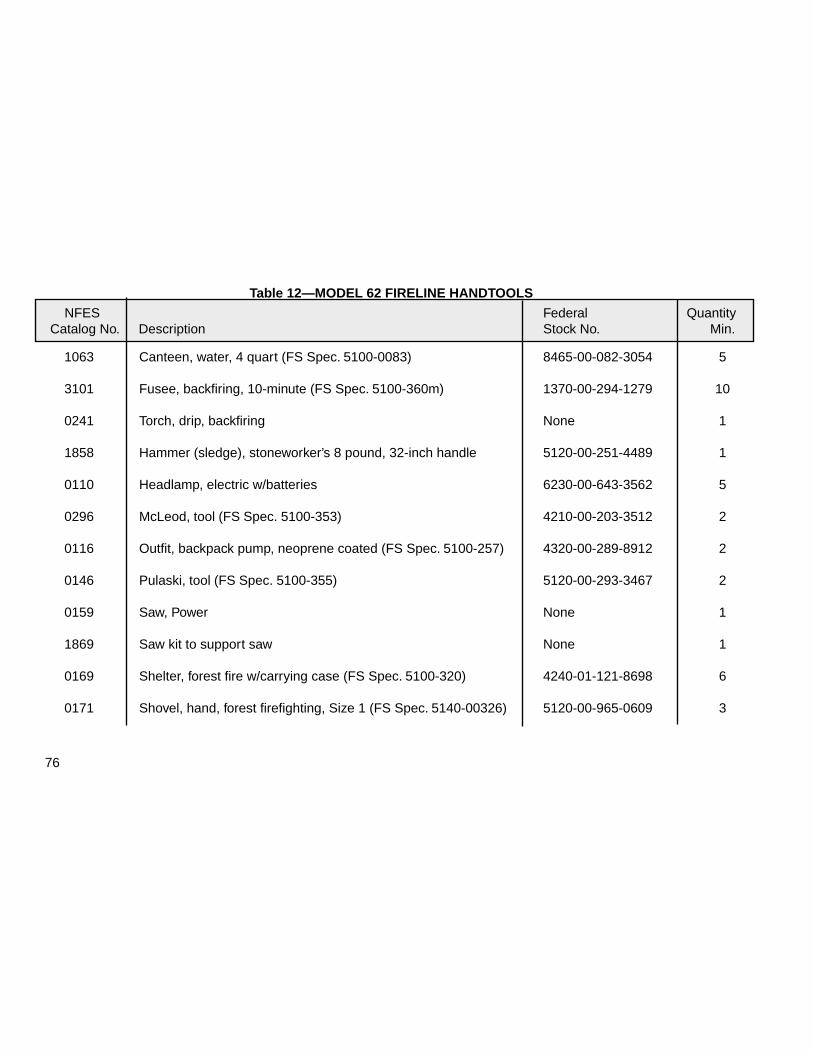
76
Table 12—MODEL 62 FIRELINE HANDTOOLS
NFES Federal Quantity Catalog No. Description Stock No. Min.
1063 Canteen, water, 4 quart (FS Spec. 5100-0083) 8465-00-082-3054 5
3101 Fusee, backfiring, 10-minute (FS Spec. 5100-360m) 1370-00-294-1279 10
0241 Torch, drip, backfiring None 1
1858 Hammer (sledge), stoneworker’s 8 pound, 32-inch handle 5120-00-251-4489 1
0110 Headlamp, electric w/batteries 6230-00-643-3562 5
0296 McLeod, tool (FS Spec. 5100-353) 4210-00-203-3512 2
0116 Outfit, backpack pump, neoprene coated (FS Spec. 5100-257) 4320-00-289-8912 2
0146 Pulaski, tool (FS Spec. 5100-355) 5120-00-293-3467 2
0159 Saw, Power None 1
1869 Saw kit to support saw None 1
0169 Shelter, forest fire w/carrying case (FS Spec. 5100-320) 4240-01-121-8698 6
0171 Shovel, hand, forest firefighting, Size 1 (FS Spec. 5140-00326) 5120-00-965-0609 3
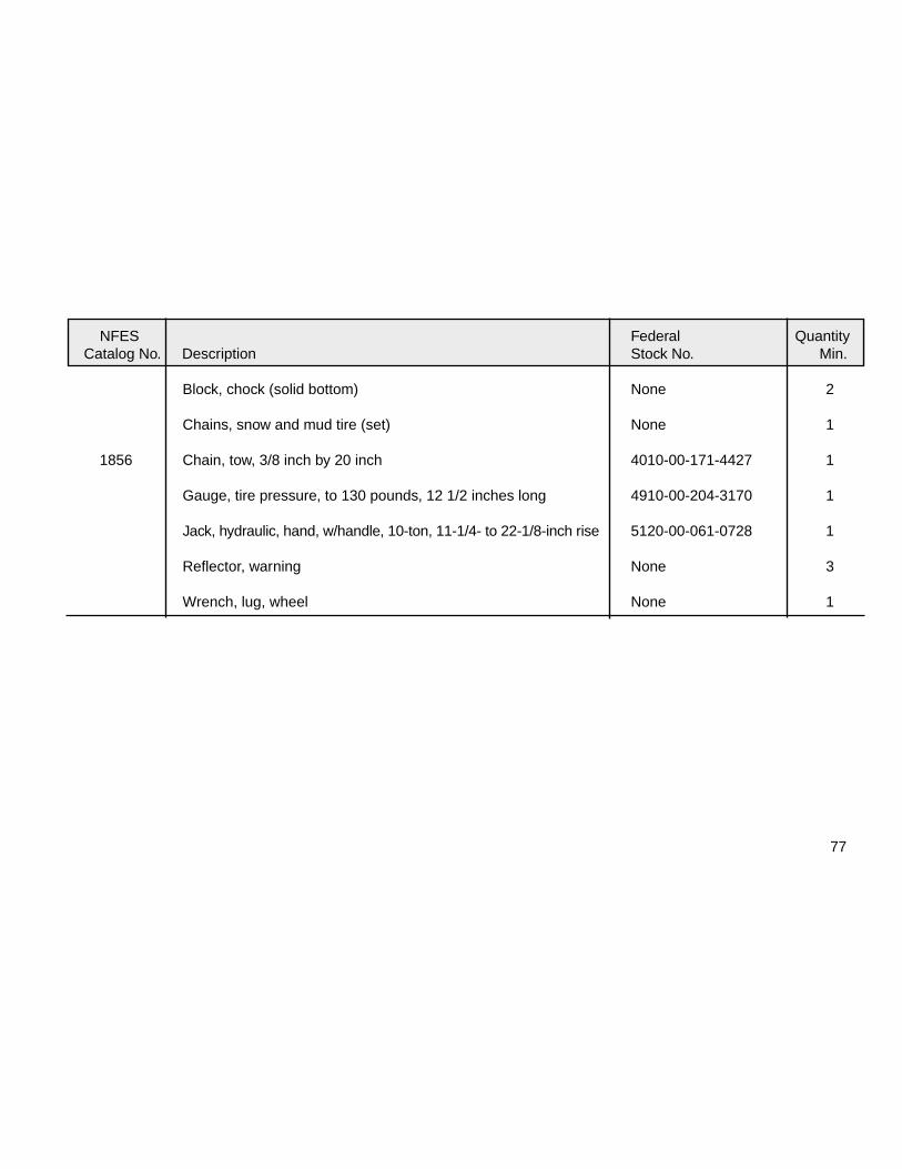
77
NFES Federal Quantity Catalog No. Description Stock No. Min.
Block, chock (solid bottom) None 2
Chains, snow and mud tire (set) None 1
1856 Chain, tow, 3/8 inch by 20 inch 4010-00-171-4427 1
Gauge, tire pressure, to 130 pounds, 12 1/2 inches long 4910-00-204-3170 1
Jack, hydraulic, hand, w/handle, 10-ton, 11-1/4- to 22-1/8-inch rise 5120-00-061-0728 1
Reflector, warning None 3
Wrench, lug, wheel None 1


79
APPENDIXMETRIC EQUIVALENTS
This appendix is designed for use as a ready reference to convert the English units used in this Guide into metricequivalents for measurements commonly used by firefighters.
English Multiply To Obtain MetricValue In by Equivalent In
Lengthinches (in) x 25.4 = millimeters (mm)feet (ft) x 0.3048 = meters (m)
Mass (weight)pounds (lb) x 0.4536 = kilograms (kg)
(NOTE- 1 U.S. gal of water weighs 8.335 lb.)Volume (capacity), liquidgallons (gal) x 3.785 = liters (1)
(NOTE- A liter is 1,000 cubic centimeters.)Flowgallons per minute (gal/min) x 0.06308 = liters per second (L/sec)

80
English Multiply To Obtain MetricValue In by Equivalent In
Velocityfeet per second (ft/s) x 1.097 = kilometers per hour (km/h)feet per second (ft/s) x 304.8 = millimeters per second (mm/sec)miles per hour (mi/h) x 1.6093 = kilometers per hour (km/h)
Pressurepounds per square inch (psi) x 6.8947 = kilopascals (kPa)feet of water (head) x 2.99 = kilopascals (kPa)inches of mercury (draft) x 0.3048 = meters of lift
Powerhorsepower (hp) x 0.7457 = kilowatts (kW)