Embed Size (px)
Citation preview

Model 6 Motor Control CentersClass 8998
Instruction Bulletin80459-641-01DRetain for Future Use.
Courtesy of Steven Engineering, Inc.-230 Ryan Way, South San Francisco, CA 94080-6370-Main Office: (650) 588-9200-Outside Local Area: (800) 258-9200-www.stevenengineering.com

Hazard Categories and Special Symbols
Read these instructions carefully and look at the equipment to become familiar with the device before trying to install, operate, service, or maintain it. The following special messages may appear throughout this bulletin or on the equipment to warn of potential hazards or to call attention to information that clarifies or simplifies a procedure.
The addition of either symbol to a “Danger” or “Warning” safety label indicates that an electrical hazard exists which will result in personal injury if the instructions are not followed.
This is the safety alert symbol. It is used to alert you to potential personal injury hazards. Obey all safety messages that follow this symbol to avoid possible injury or death.
NOTE: Provides additional information to clarify or simplify a procedure.
Please Note Electrical equipment should be installed, operated, serviced, and maintained only by qualified personnel. No responsibility is assumed by Schneider Electric for any consequences arising out of the use of this material.
Systems Integration Disclaimer Unless performed by Schneider Electric, Schneider Electric disclaims liability for any systems integration work. Schneider Electric assumes no responsibility for application software and control systems designs supplied by a third party.
DANGERDANGER indicates an imminently hazardous situation which, if not avoided, will result in death or serious injury.
WARNINGWARNING indicates a potentially hazardous situation which, if not avoided, can result in death or serious injury.
CAUTIONCAUTION indicates a potentially hazardous situation which, if not avoided, can result in minor or moderate injury.
CAUTIONCAUTION, used without the safety alert symbol, indicates a potentially hazardous situation which, if not avoided, can result in property damage.
Courtesy of Steven Engineering, Inc.-230 Ryan Way, South San Francisco, CA 94080-6370-Main Office: (650) 588-9200-Outside Local Area: (800) 258-9200-www.stevenengineering.com

80459-641-01D Model 6 Motor Control Centers09/2008 Table of Contents
© 1999–2008 Schneider Electric All Rights Reserved 3
Table of ContentsSection 1—About the Model 6 Motor Control Center ............................. 9
Schneider Electric Literature List ........................................................... 9
Section 2—Safety Precautions ............................................................... 11
Section 3—Receiving, Handling, and Storing the MCC ....................... 12
Receiving the MCC ............................................................................. 12Handling the MCC ............................................................................... 12
Equipment Needed........................................................................ 13Moving the MCC .................................................................................. 13Storing the MCC .................................................................................. 14
Section 4—Installing the MCC ................................................................ 15
Locating the MCC ................................................................................ 15Space Requirements ..................................................................... 15Aligning the MCC........................................................................... 15
Joining NEMA Type 1 / NEMA Type 1 Gasketed / NEMA Type 12 Sections ..................................................................... 16
Positioning the MCC...................................................................... 16Joining Corner Channels ............................................................... 17Securing Structures to the Floor.................................................... 18
Seismic Certification of Model 6 MCCs ............................................... 19Responsibility for Mitigation of Seismic Damage........................... 19Securing Structures to Floor—Seismic Hazard Designated Locations .................................................................... 20Securing Structures to Wall—Seismic Hazard Designated Locations .................................................................... 22
Splice Gaskets for NEMA Type 1 Gasketed and Type 12 Enclosures 23Splicing With No P Gasketing ............................................................. 24Splicing With P Gasketing ................................................................... 24
Splice to Existing Left .................................................................... 24Splice to Existing Right .................................................................. 24
Joining New Style NEMA Type 3R Enclosures to Old Style NEMA Type 3R Enclosures ................................................................. 25
Joining to the Left Side of an Existing NEMA Type 3R MCC Enclosure. ............................................................................ 25Joining to the Right Side of an Existing NEMA Type 3R MCC Enclosure ............................................................................. 28
Joining NEMA Type 3R Sections ........................................................ 29Splicing Power Bus for NEMA Type 1 and Type 12 Enclosures ......... 30Splicing Power Bus in NEMA Type 3R Enclosures ............................. 32Ground Bus Splicing for NEMA Type 1, Type 12, and Type 3R ......... 33Power Bus Splicing of Two-Inch (51 mm) Bus with 100,000 A Short Circuit ....................................................................... 34Splicing Offset Horizontal Bus (Left Side of Structure Only) ............... 36Conductor Entry .................................................................................. 37Vent Hood Installation for MCCs with 2500 A Horizontal Bus ............. 37Vented Pullbox Installation for MCCs with 2500 A Horizontal Bus ............39Load and Control Wiring ...................................................................... 40Crimp Lug Cable Assembly for Cabled Disconnect Unit Installation ... 41Cable Connection Torque Values ....................................................... 42Component Instructional Information .................................................. 42Modifying Fuse Clip Locations ............................................................ 43
Courtesy of Steven Engineering, Inc.-230 Ryan Way, South San Francisco, CA 94080-6370-Main Office: (650) 588-9200-Outside Local Area: (800) 258-9200-www.stevenengineering.com

Model 6 Motor Control Centers 80459-641-01DTable of Contents 09/2008
© 1999–2008 Schneider Electric All Rights Reserved4
Section 5—Operation............................................................................... 44
Pre-operation Checklist ....................................................................... 44Energizing the MCC ............................................................................ 45
Section 6—Maintaining the MCC ............................................................ 46
Examining the Enclosure ..................................................................... 46Maintaining Bus Bars and Incoming Line Compartments .................... 46Maintaining the Control Unit ................................................................ 47Removing the Control Unit .................................................................. 48Removing the Compac™ 6 Control Unit ............................................. 51Tests and Maintenance Performed with the Control Unit Removed .... 52Reassembly ......................................................................................... 55Insulation Test ..................................................................................... 56Maintenance after a Fault Has Occurred ............................................. 57
Section 7—Motor Logic® Solid-State Overload Relay (SSOLR) .......... 59
Motor Logic Retrofit Applications ......................................................... 60Adjustment ........................................................................................... 62
Section 8—Mag-Gard® and PowerPact® Motor Circuit Protector Settings ..................................................................................................... 63
Adjusting Mag-Gard or PowerPact Magnetic Trip Setting ................... 63
Section 9—iMCC ...................................................................................... 65
iMCC Overview ......................................................................................... 65Networks/Communications Overview ....................................................... 65Connecting the iMCC Cabling System ...................................................... 66
Network Cabling .................................................................................. 66Cables Between Shipping Splits .......................................................... 66Load Cables ........................................................................................ 66
Communication Networks ......................................................................... 66Bridges/Repeaters ............................................................................... 66Terminating Resistors .......................................................................... 66Direct Cable Connection ...................................................................... 66
Operation .................................................................................................. 70Pre-operation Checklists ..................................................................... 70
MCC Structure ............................................................................... 70iMCC Communications .................................................................. 71
Energizing the MCC ............................................................................ 71Motor Logic Plus Local Programming ............................................ 72Motor Logic Plus Remote Programming ........................................ 73
TeSys® T Motor Management Controller .................................................. 77TeSys T Retrofit Applications .............................................................. 78Applications Requiring Turns ............................................................... 78TeSys T Local Programming ............................................................... 79
Configuring with HMI...................................................................... 79Configuring with PowerSuite™ Software ....................................... 80
PowerLogic® Power Meter Series 800 ................................................ 80PowerLogic Circuit Monitor .................................................................. 80Altivar® 61/71 ...................................................................................... 80Altistart® 48 ......................................................................................... 80Device Addressing ............................................................................... 81Software .............................................................................................. 81
Courtesy of Steven Engineering, Inc.-230 Ryan Way, South San Francisco, CA 94080-6370-Main Office: (650) 588-9200-Outside Local Area: (800) 258-9200-www.stevenengineering.com

80459-641-01D Model 6 Motor Control Centers09/2008 Table of Contents
© 1999–2008 Schneider Electric All Rights Reserved 5
Section 10—Expansion ........................................................................... 82
Ordering Information ........................................................................... 82Modifying MCC Units ........................................................................... 82
De-Energizing Equipment and Identifying Unit Type...................................................................... 82Modifying Removable Units........................................................... 83Modifying Fixed Units .................................................................... 83
Installing Additional MCC Units ........................................................... 84Compac 6 Units ................................................................................... 86Control and Load Wiring ...................................................................... 86Cable Connection Torque Values ....................................................... 87Compac 6 Control Unit Installation ...................................................... 88
Section 11—Troubleshooting ................................................................. 89
Section 12—Insulation Resistance ........................................................ 93
Thermal Overload Unit Selection ........................................................ 94
Section 13—Circuit Breaker and Fusible Switch Replacement......... 100
Section 14—Installation and Maintenance Log................................... 101
Appendix A—Removal and Installation of Horizontal Bus Barrier Panels................................................................................. 102
Removal ............................................................................................ 102Installation ......................................................................................... 103
Fixed Barrier ........................................................................................... 104Removal ............................................................................................ 104Installation ......................................................................................... 105
Appendix B—Non-Conductive Horizontal Bus Barrier Retrofit Kit ............................................................................................... 106
Remove Existing Components ................................................................ 107Horizontal Wireway Cover ................................................................. 107Horizontal Bus Barriers ..................................................................... 107Units Below the Topshelf ................................................................... 107Existing Brackets: 15 in. (381 mm) Deep MCC Only ........................ 107
Install the Retrofit Kit ............................................................................... 108Retrofit Brackets and Endcaps .......................................................... 108Bottom Track and Bottom Retrofit Bracket ........................................ 110Left and Right Panels ........................................................................ 111
Installation ................................................................................... 111Removal (when required) ............................................................ 112
Replace Components ............................................................................. 112
Appendix C—Automatic Vertical Bus Shutter .................................... 113
Introduction ............................................................................................. 113Installation—Style 1 ................................................................................ 114Removal—Style 1 ................................................................................... 116Installation—Style 2 ................................................................................ 117Removal—Style 2 ................................................................................... 118Operation—Styles 1 and 2 ...................................................................... 119
Inserting a Unit .................................................................................. 119Removing a Unit ................................................................................ 119
Appendix D—Technical Support .......................................................... 120
Index........................................................................................................ 121
Courtesy of Steven Engineering, Inc.-230 Ryan Way, South San Francisco, CA 94080-6370-Main Office: (650) 588-9200-Outside Local Area: (800) 258-9200-www.stevenengineering.com

Model 6 Motor Control Centers 80459-641-01DList of Figures 09/2008
© 1999–2008 Schneider Electric All Rights Reserved6
List of Figures Figure 1: Packaged Motor Control Center .......................................... 12Figure 2: Moving the MCC with a Fork Truck ..................................... 13Figure 3: Proper Use of a Sling to Lift MCC ........................................ 13Figure 4: Motor Control Center Views ................................................. 16Figure 5: Base Channel Notches ........................................................ 17Figure 6: Hardware Kit ........................................................................ 17Figure 7: Bolting Sections Together .................................................... 17Figure 8: Standard Base Channel Mounting ....................................... 18Figure 9: NEMA Type 1, Type 1 Gasketed, and Type 12 Seismic
Tie-Down Locations ............................................................. 20Figure 10: NEMA Type 3R Seismic Tie-Down Locations ..................... 21Figure 11: Attachment Locations for Top Lateral Bracing ..................... 22Figure 12: P Gasketing ......................................................................... 23Figure 13: Removing the End Deflector ................................................ 25Figure 14: Removing the Insulating Barrier .......................................... 26Figure 15: Installing the Deflector Bracket ............................................ 26Figure 16: Re-attaching the Back Plates .............................................. 27Figure 17: Installing the Splice Deflector .............................................. 28Figure 18: Remove Mid and End Deflector Caps from the Top
of the MCC ........................................................................... 29Figure 19: Attach the Multi-section Bracket .......................................... 29Figure 20: Secure the Vertical Channels .............................................. 29Figure 21: Replace Lifting Angle Hardware .......................................... 29Figure 22: Horizontal Wireway Covers and
Bus Barriers Removed ......................................................... 30Figure 23: Removing the Left Bolts and Loosening the Right Bolts
on the Splice Assembly ....................................................... 30Figure 24: Aligning the Splice and Bus Holes ....................................... 31Figure 25: Inserting the Splice Bolts ..................................................... 31Figure 26: Placing a Conical Washer Under the Bolt Head .................. 31Figure 27: Torquing the Bolts ................................................................ 31Figure 28: Wireway Covers Removed and Horizontal Bus Barriers
Open .................................................................................... 32Figure 29: Loosen Bolts ........................................................................ 32Figure 30: Slide the Splice Assembly to the Left .................................. 32Figure 31: Inserting the Splice Bolts ..................................................... 33Figure 32: Place a Conical Washer Under the Bolt Head ..................... 33Figure 33: Torque All Bolts ................................................................... 33Figure 34: Ground Splice Bar as Shipped ............................................ 33Figure 35: Ground Bar Bolt Replaced ................................................... 34Figure 36: Wireway Covers Removed and Horizontal Bus Barriers
Open .................................................................................... 34Figure 37: Removing the Bolts from the Splice Assembly .................... 35Figure 38: Aligning the Splice and Bus Holes ....................................... 35Figure 39: Inserting the Splice Bolts ..................................................... 35Figure 40: Place a Conical Washer Under the Bolt Head ..................... 35Figure 41: Torque All Bolts ................................................................... 35Figure 42: Splicing Offset Horizontal Bus ............................................. 36Figure 43: Remove the Hardware ......................................................... 38Figure 44: Reposition and Attach the Vent Hood .................................. 38Figure 45: Remove the Hardware ......................................................... 39Figure 46: Install the Pullbox ................................................................. 39Figure 47: Wiring in the Top Horizontal Wire Trough ............................ 40Figure 48: Vertical Wire Trough Grommet ............................................ 40Figure 49: Pull-apart Type Terminal Blocks .......................................... 40Figure 50: Typical Cabled Disconnect Unit ........................................... 41Figure 51: Typical Horizontal Bus Assembly ........................................ 41Figure 52: Main Lug Compartment Torque Connection ........................ 42
Courtesy of Steven Engineering, Inc.-230 Ryan Way, South San Francisco, CA 94080-6370-Main Office: (650) 588-9200-Outside Local Area: (800) 258-9200-www.stevenengineering.com

80459-641-01D Model 6 Motor Control Centers09/2008 List of Figures
© 1999–2008 Schneider Electric All Rights Reserved 7
Figure 53: Size 1 and 2 Fuse Clip Locations ........................................ 43Figure 54: Pre-operation Check ........................................................... 44Figure 55: Typical Bus Connection Points ............................................ 46Figure 56: Main Lug Compartment Torque Connection ....................... 47Figure 57: Control Unit ......................................................................... 47Figure 58: Operator Mechanism in the Off Position ............................. 48Figure 59: Loosening Captive Quarter-Turn Fasteners ........................ 48Figure 60: Releasing the Lock-in Device (when supplied) ................... 48Figure 61: Disconnected Terminal Blocks ............................................ 48Figure 62: Power Leads and Top of Terminal Blocks Fed Through
Wiring Port ........................................................................... 49Figure 63: Pulling the Twin Handle Cam Mechanism Forward ............ 49Figure 64: Operating the Mechanism-to-Structure Interlock ................. 49Figure 65: Locked Out Device .............................................................. 49Figure 66: Control Unit Removed ......................................................... 50Figure 67: Control Unit with Bottom Plate Folded Down ...................... 50Figure 68: Driving Out Hinge Pin .......................................................... 50Figure 69: Operator Handle in the Off Position .................................... 51Figure 70: Loosening Captive Quarter-Turn Fasteners ........................ 51Figure 71: Control Station Plate Removed ........................................... 51Figure 72: Operator Handle and Interlock Release .............................. 52Figure 73: Stab Assembly .................................................................... 52Figure 74: Operator Mechanism in the Tripped Position ...................... 53Figure 75: Inspecting Fuses ................................................................. 53Figure 76: Starter Contacts .................................................................. 53Figure 77: Control Devices ................................................................... 54Figure 78: Tripping the Overload Relay ................................................ 54Figure 79: Tightening Electrical Connections ....................................... 54Figure 80: Manual and Automatic Bus Shutters ................................... 55Figure 81: Typical Bus Connection Points ............................................ 58Figure 82: Operating Door Interlock Defeat Mechanism ...................... 58Figure 83: Motor Logic® SSOLR .......................................................... 59Figure 84: NEMA Rated Compac™ 6 Unit ........................................... 59Figure 85: NEMA Rated Standard Unit ................................................ 59Figure 86: Looping Passes ................................................................... 61Figure 87: Motor Logic Overload (Bottom View) .................................. 61Figure 88: Unit Adjustment Label ......................................................... 62Figure 89: Mag-Gard® Magnetic Trip Adjustment ................................ 63Figure 90: PowerPact® H- and J-frame Magnetic Trip Adjustment ...... 64Figure 91: PowerPact P-frame Instantaneous Trip Adjustment ........... 64Figure 92: Typical Cabling Scheme for Modbus® Two-Wire ................ 67Figure 93: Typical Cabling Scheme for DeviceNet™ and
CANopen (8A cable) ........................................................... 68Figure 94: Typical Cabling Scheme for PROFIBUS ............................. 69Figure 95: Motor Logic Plus™ Communication Module Terminals ...... 72Figure 96: TeSys® T Controllers ........................................................... 77Figure 97: NEMA Rated Control Unit (TeSys T Modbus) ..................... 77Figure 98: Shelf and Door Installation .................................................. 84Figure 99: Cutting the Vertical Wire Trough Grommet (when supplied) 85Figure 100: Removing the Manual Bus Shutter ...................................... 85Figure 101: Engaging the Cam Mechanism ........................................... 85Figure 102: Handles Flush with the Front of the MCC ........................... 85Figure 103: Tightening the Control Unit Lock-in Panel (when supplied) 85Figure 104: Power Leads Connected to Power Terminals ..................... 86Figure 105: Connecting Control Leads to the Terminal Blocks .............. 86Figure 106: Pull-apart Terminals ............................................................ 86Figure 107: Typical Unit Torque Label ................................................... 87Figure 108: Fuse Bases ......................................................................... 87
Courtesy of Steven Engineering, Inc.-230 Ryan Way, South San Francisco, CA 94080-6370-Main Office: (650) 588-9200-Outside Local Area: (800) 258-9200-www.stevenengineering.com
Model 6 Motor Control Centers 80459-641-01DList of Figures 09/2008
© 1999–2008 Schneider Electric All Rights Reserved8
Figure 109: Reinstalling the Compac 6 Control Unit ............................... 88Figure 110: Circuit Breaker Replacement ............................................. 100Figure 111: Aligning the Arrows on the Panels ..................................... 102Figure 112: Right Panel (Side View) ..................................................... 103Figure 113: Installing the Right Panel into the Rear Groove ................. 103Figure 114: Fixed Horizontal Bus Barrier .............................................. 104Figure 115: Horizontal Bus Barrier Installation and Removal ............... 105Figure 116: Barrier Installed and Removed .......................................... 105Figure 117: Retrofit Kit Components ..................................................... 106Figure 118: Remove Existing Brackets on the 15 in. (381 mm)
Deep MCC ......................................................................... 107Figure 119: 15 in. (381 mm) Deep MCC Retrofit Bracket ..................... 108Figure 120: 20 in. (508 mm) Deep MCC Retrofit Bracket ..................... 109Figure 121: Endcap Placement ............................................................. 109Figure 122: Horizontal Bus Barrier (L-shaped) Bracket ........................ 110Figure 123: Welded and Relay Topshelf Assemblies ........................... 110Figure 124: Right Panel (Side View) ..................................................... 111Figure 125: Installing the Right Panel into the Rear Groove ................. 111Figure 126: Aligning the Arrows on the Panels ..................................... 112Figure 127: Location of Auto-Shutter Cover for Side-Panel Opening ... 113Figure 128: Automatic Vertical Bus Shutter in an MCC (front view) ..... 114Figure 129: Shelf Installation—Style 1 .................................................. 115Figure 130: Automatic Vertical Bus Shutter Installation—Style 1 ......... 115Figure 131: Automatic Vertical Bus Shutter Removal—Style 1 ............ 116Figure 132: Shelf Installation—Style 2 .................................................. 117Figure 133: Automatic Vertical Bus Shutter Installation—Style 2 ......... 118Figure 134: Automatic Vertical Bus Shutter Removal—Style 2 ............ 119
LIST OF TABLES Table 1: MCC and iMCC Related Literature ........................................ 9Table 2: Approximate MCC Shipping Weights .................................. 13Table 3: Connection Torque Values for Main Lug Compartments..... 42Table 4: Connection Torque Values for Main and Branch Feeders... 42Table 5: Bus Connection Torque Values........................................... 46Table 6: Bus Connection Torque Values .......................................... 58Table 7: Lug Types and Wire Sizes................................................... 61Table 8: Pin Outs for iMCC Networks................................................ 66Table 9: Network Connection Pin Outs.............................................. 66Table 10: Local Error Display .............................................................. 73Table 11: Command Line Codes......................................................... 73Table 12: Motor Logic Plus Address Descriptions ............................... 74Table 13: Read-Only Registers ........................................................... 75Table 14: Read/Write Registers........................................................... 76Table 15: Shelf Installation Kit Parts.................................................... 84Table 16: Motor Control Center Troubleshooting Chart....................... 90Table 17: Shelf Installation Kit Parts—Style 1 ................................... 115Table 18: Shelf Installation Kit Parts—Style 2 ................................... 117
Courtesy of Steven Engineering, Inc.-230 Ryan Way, South San Francisco, CA 94080-6370-Main Office: (650) 588-9200-Outside Local Area: (800) 258-9200-www.stevenengineering.com

80459-641-01D Model 6 Motor Control Centers09/2008 Section 1—About the Model 6 Motor Control Center
© 1999–2008 Schneider Electric All Rights Reserved 9
Section 1—About the Model 6 Motor Control Center
Motor control centers (MCCs) provide the most suitable method for grouping electrical motor control and other related devices in a compact, economical, and free-standing installation. A motor control center is made of standardized vertical sections consisting of totally enclosed, dead front, free-standing structures bolted together. These sections support and house control units, a common bus bar for distributing power to the control units, and a network of wire trough and conductor entrance areas to accommodate outgoing load and control wires.
The control units consist of components such as combination motor starters, branch feeder devices, and lighting panelboards. Each is mounted in an individual, isolated compartment having its own cover. When front-of-board unit arrangement is selected, all units are mounted on the front side of the MCC. A 15 in. (381 mm) or 20 in. (508 mm) deep section is provided for front-of-board mounting. The standard MCC width is 20 in. (508 mm) with a 4 in. (102 mm) wide vertical wireway.
An optional 25 in. (635 mm) wide section with a 9 in. (229 mm) wide wireway is also available. Larger sections are available for mounting larger equipment. When a back-to-back arrangement is selected, the units are mounted on both the front and rear of 31 in. (787 mm) or 41 in. (1041 mm) deep structures. Approximately 1 in. (25 mm) of space is between back-to-back sections. The standard height of all MCC structures is 91.5 in. (2324 mm) without the 3 in. (76.2 mm) lifting angle.
Schneider Electric Literature List The following Schneider Electric publications may be useful in the maintenance and regular operation of your Model 6 MCC. Your Schneider Electric field sales representative can provide them upon your request. Or, you can download these documents from the Technical Library at www.schneider-electric.us.
Table 1: MCC and iMCC Related Literature
Publication No. Title Publication No. Title
MCC Related Literature
8998CT9701 Motor Control Centers (Model 6 Catalog, Class 8998) 30072-013-25 AC Magnetic Contactors and Starters, Size 3
80444-233-01 Altivar® 61/71 Adjustable Speed Drive Controllers in Motor Control Centers 30072-013-26 AC Magnetic Contactors and Starters, Size 4
80438-069-02 Altistart® 48 Soft Start Units in Motor Control Centers 30072-013-47 AC Magnetic Contactors and Starters, Size 5
30072-013-29 Motor Logic® Solid-State Overload Relay 30072-013-60 AC Magnetic Contactors and Starters, Size 6
30072-013-98 Motor Logic Plus™ Programmable Solid-State Overload Relay 3020IM9503 PowerLogic® Power Meter
30072-013-99 Motor Logic Plus Solutions Software 3020IM9806 PowerLogic Circuit Monitor Series 2000 Reference Manual
30072-013-101 Motor Logic Plus Lug-Lug Kit 63230-400-207 PowerLogic Circuit Monitor Series 3000 Reference Manual
30072-013-102 Motor Logic Plus Network Communication Module 63230-300-213 PowerLogic Circuit Monitor Series 4000 Reference
Manual
30072-013-52 AC Magnetic Contactors and Starters, Size 00 0100PL0701 Square D Digest 174
30072-013-22 AC Magnetic Contactors and Starters, Size 0 63230-500-224 PM820, PM850, PM870 Installation
30072-013-23 AC Magnetic Contactors and Starters, Size 1 63230-500-225 PM820, PM850, PM870 Reference Manual
30072-013-24 AC Magnetic Contactors and Starters, Size 2
Courtesy of Steven Engineering, Inc.-230 Ryan Way, South San Francisco, CA 94080-6370-Main Office: (650) 588-9200-Outside Local Area: (800) 258-9200-www.stevenengineering.com

Model 6 Motor Control Centers 80459-641-01DSection 1—About the Model 6 Motor Control Center 09/2008
© 1999–2008 Schneider Electric All Rights Reserved10
iMCC Related Literature
atv71_parameters_en Altivar® 71 Communication Parameters User’s Manual 1639508_01a55 LTM R - Instruction Sheet
atv71_programming_manual_en Altivar 71 Programming Manual 1639509_01a55 LTM E - Instruction Sheet
atv71_Modbus_EN Altivar 71 Modbus®/Uni-Telway™ Card—Modbus protocol 1639582_01a55 LTM CU - Instruction Sheet
atv71_Uni-Telway_EN Altivar 71 Modbus/Uni-Telway card—UniTelway protocol 840USE10000 Modicon® TSX Quantum Automation Series
890USE10300 Modicon Modbus Plus™ Network BM85 Bridge Multiplexer User’s Guide 840USE11300 Modicon XMIT Function Block
Modicon TSX Quantum Automation Series www.modicon.com/specguide98/ 840USE11600 Quantum NOE 771 X0 Ethernet Modules User Guide
PI-MBUS-300 Modicon − Modbus Protocol Reference Guide 870USE00200 TSX Momentum™ I/0 Base User Guide
30072-013-98 Motor Logic Plus™ Programmable Solid-State Overload Relay 870USE10100 Modicon TSX Momentum M1 Processor Adapter and
Option Adapter User Manual
30072-013-99 Solutions Software for Motor Logic Plus SSOL 870USE11400 Ethernet Communications Adapter
30072-013-101 Motor Logic Plus Lug-Lug Kit 890USE10000 Modicon Modbus Plus Network Planning/Installation Guide
30072-013-102 Motor Logic Plus Network Communication Module 30072-450-61 Altistart® 48 Y-Range Soft Start Controllers
1639501 TeSys® T LTM R Modbus Motor Management Controller User’s Manual 3000DB0001 PowerLogic® System Architecture and Application
Guide
1639505 TeSys T LTM R Modbus/TCP Motor Management Controller User's Manual 3020IB9818 PowerLogic Ethernet Communication Module, Models
ECM-2000 and ECM-RM
1639502 TeSys T LTM R PROFIBUS Motor Management Controller User's Manual 63230-500-200 PowerLogic Series 800 Power Meter Installation
Manual—PM810
1639504 TeSys T LTM R DeviceNet™ Motor Management Controller User’s Manual 63230-500-224 PowerLogic Series 800 Power Meter Installation
Manual—PM820, PM850, PM870
1639503 TeSys T LTM R CANopen Motor Management Controller User's Manual 63230-400-204 PowerLogic Circuit Monitor Series 3000 Installation
Manual
1639581 TeSys T LTM CU Control Operator Unit User’s Manual 63230-300-209 PowerLogic Circuit Monitor Series 4000 Installation
Manual
1639572 TeSys T LTM R Modbus Motor Management Controller Quick Start Guide 3050IM9601 PowerLogic Ethernet Gateway
1639576 TeSys T LTM R Modbus/TCP Motor Management Controller Quick Start Guide 3080HO9601 System Manager™ Software SMS-3000
1639573 TeSys T LTM R PROFIBUS-DP® Motor Management Controller Quick Start Guide 3080IB9803 PL, PowerLogic System Manager 3000
1639575 TeSys T LTM R DeviceNet Motor Management Controller Quick Start Guide 3080IM9603 Ethernet Driver for System Manager
1639574 TeSys T LTM R CANopen Motor Management Controller Quick Start Guide
Table 1: MCC and iMCC Related Literature
Publication No. Title Publication No. Title
Courtesy of Steven Engineering, Inc.-230 Ryan Way, South San Francisco, CA 94080-6370-Main Office: (650) 588-9200-Outside Local Area: (800) 258-9200-www.stevenengineering.com

80459-641-01D Model 6 Motor Control Centers09/2008 Section 2—Safety Precautions
© 1999–2008 Schneider Electric All Rights Reserved 11
Section 2—Safety Precautions
Carefully read and follow the safety precautions before attempting to lift, move, install, use, or maintain Model 6 MCCs and their components.
DANGERHAZARD OF ELECTRIC SHOCK, EXPLOSION, OR ARC FLASH
• Apply appropriate personal protective equipment (PPE) and follow safe electrical work practices. See NFPA 70E.
• This equipment must only be installed and serviced by qualified electrical personnel.
• Qualified electrical personnel must perform work in accordance with all applicable national and local electrical codes.
• Perform such work only after reading and understanding all of the instructions contained in this bulletin.
• Follow all safety procedures defined in NFPA-70E and OSHA 1910.331-35, as well as those established by your specific location.
• Turn off all power supplying this equipment before working on or inside equipment.
• Assume that all circuits are live until they have been completely de-energized, tested, locked out, and/or tagged out (per OSHA 1910.147). Pay particular attention to the design of the power system. Consider all sources of power, including the possibility of backfeeding.
• Always use a properly rated voltage sensing device to confirm power is off.• Replace all devices, doors, and covers before turning on power to this
equipment.
Failure to follow this instruction will result in death or serious injury.
Courtesy of Steven Engineering, Inc.-230 Ryan Way, South San Francisco, CA 94080-6370-Main Office: (650) 588-9200-Outside Local Area: (800) 258-9200-www.stevenengineering.com

Model 6 Motor Control Centers 80459-641-01DSection 3—Receiving, Handling, and Storing the MCC 09/2008
© 1999–2008 Schneider Electric All Rights Reserved12
Section 3—Receiving, Handling, and Storing the MCC
MCCs are constructed in shipping blocks of up to three vertical sections. This allows for ease of handling during transportation and installation. The main horizontal bus of all shipping blocks will be spliced together at the job site with the use of captive horizontal splice bars.
Before shipment from the factory, the MCC is inspected visually, electrically, and mechanically by professional quality control analysts. Certification of quality control testing is available upon request.
After leaving Quality Control, each shipping block is carefully packaged and attached to a skid (see Figure 1).
Receiving the MCC Inspect the MCC for damage as soon as it is received. Delivery of the equipment to a carrier at any of the Schneider Electric plants or other shipping point constitutes delivery to the purchaser. Title and all risk of loss or damage in transit shall pass to the purchaser at that time. Refer to the Schneider Electric Conditions of Sale for more details. All claims for loss and damage must be made by the purchaser to the carrier.
If the packaging material is removed, replace it for protection until the MCC is installed.
Handling the MCC
Figure 1: Packaged Motor Control Center
WARNINGHAZARD OF BODILY INJURY OR EQUIPMENT DAMAGE
• Use extreme caution when moving sections. The MCC has a high center of gravity, which may cause it to tilt.
• Do not attempt to lift or attach lifting means to sections equipped with pull boxes.
Failure to follow this instruction can result in death or serious injury.
Courtesy of Steven Engineering, Inc.-230 Ryan Way, South San Francisco, CA 94080-6370-Main Office: (650) 588-9200-Outside Local Area: (800) 258-9200-www.stevenengineering.com

80459-641-01D Model 6 Motor Control Centers09/2008 Section 3—Receiving, Handling, and Storing the MCC
© 1999–2008 Schneider Electric All Rights Reserved 13
Equipment Needed Adequate equipment, such as a fork truck, crane, or rods and pipe rollers, must be available for handling MCCs. Table 2 lists the approximate shipping weights of sections equipped with typical units.
Moving the MCC As shown in Table 2, weights vary by enclosure type and depth. To minimize the risk of injury and equipment damage while moving the MCC, follow these guidelines:
• Use caution when moving heavy equipment.• Verify that the moving equipment is rated to handle the weight.• Fork trucks, when available, provide a convenient method of moving
MCCs (see Figure 2). When removing an MCC from a shipping pallet, carefully balance and secure it using a safety strap.
• Each shipping block has lifting angles for handling the MCC with overhead cranes. Take the following precautions when using a crane:
a. Handle MCCs in the upright position only.b. Select rigging lengths to compensate for any unequal weight
distribution. c. Do not exceed the 45° maximum angle between the vertical and
lifting cables (see Figure 3).d. Use only slings with safety hooks or shackles. Do not pass ropes or
cables through the holes in the lifting angle.
Table 2: Approximate MCC Shipping Weights
Enclosure Type Depth One Section
Two Sections
Three Sections
NEMA 1, 1A, 12 15 in.(381 mm)
600 lb(272 kg)
1200 lb(544 kg)
1800 lb(816 kg)
NEMA 3R Non-Walk-In15 in.
(381 mm)(26.6 in. / 676 mm overall)
900 lb(408 kg)
1800 lb(816 kg)
2700 lb(1225 kg)
NEMA 1, 1A, 12 20 in.(508 mm)
750 lb(340 kg)
1500 lb(680 kg)
2250 lb(1021 kg)
NEMA 3R Non-Walk-In20 in.
(508 mm)(31.6 in. / 803 mm overall)
1050 lb(476 kg)
2100 lb(953 kg)
3150 lb(1429 kg)
Figure 2: Moving the MCC with a Fork Truck
Figure 3: Proper Use of a Sling to Lift MCC
Do not pass ropes or cables through lift holes. Use slings with safety hooks or shackles.
A
45° max1/2 A
or more
Courtesy of Steven Engineering, Inc.-230 Ryan Way, South San Francisco, CA 94080-6370-Main Office: (650) 588-9200-Outside Local Area: (800) 258-9200-www.stevenengineering.com

Model 6 Motor Control Centers 80459-641-01DSection 3—Receiving, Handling, and Storing the MCC 09/2008
© 1999–2008 Schneider Electric All Rights Reserved14
After the shipping section is in place, its lifting angle may be removed and discarded. To prevent the entrance of foreign materials, replace all hardware that secured the lifting angle.
NOTE: Do not attempt to lift or attach lifting means to sections equipped with pull boxes.
Storing the MCC
If the MCC cannot be placed into service upon receipt, store it in a clean, dry, ventilated building free from temperature extremes. Acceptable storage temperatures are from 0 °C (32 °F) to 40 °C (104 °F).
If the storage area is cool and/or damp, provide enough heat to prevent condensation inside the MCC. Contact your Schneider Electric field sales representative for specific requirements.
CAUTIONEQUIPMENT DAMAGE HAZARD
Never store MCCs outdoors. Outdoor storage is inadequate, even with the protection of a tarpaulin.
Failure to follow this instruction can result in equipment damage.
Courtesy of Steven Engineering, Inc.-230 Ryan Way, South San Francisco, CA 94080-6370-Main Office: (650) 588-9200-Outside Local Area: (800) 258-9200-www.stevenengineering.com

80459-641-01D Model 6 Motor Control Centers09/2008 Section 4—Installing the MCC
© 1999–2008 Schneider Electric All Rights Reserved 15
Section 4—Installing the MCC
This section explains how to locate, install, and join Model 6 MCC enclosures, and how to splice power and ground bus. Refer to MCC front elevation drawings supplied by Schneider Electric for location/placement of shipping splits/sections within each MCC line-up. For information related to removing and installing existing and new units, see “Section 10—Expansion” on page 82, or the information included with the shipment of the new device.
Locating the MCC
MCCs are designed for use in non-hazardous locations. Choose a location for installation that is well ventilated and free from excess humidity, dust, and dirt. The temperature of the area should be no less than 0 °C (32 °F) and no greater than 40 °C (104 °F). Protect the enclosure from the entrance of water or any moisture.
Space Requirements Install MCCs in an area with a minimum of 3 ft. (914 mm) of free space in front of front-of-board construction. An additional 3 ft. (914 mm) is necessary in the rear of back-to-back construction. This free space provides adequate room to remove and install units. (More space may be required for some applications; refer to applicable local and national installation codes.) Provide at least 0.5 in. (13 mm) of space between the back of front-of-board MCCs and a wall. For damp locations, provide at least 6 in. (152 mm).
When selecting a location for the installation of an MCC, carefully consider accessibility, overhead clearances, and future expansions. Considering these factors will eliminate many difficulties during this and future MCC installations.
Aligning the MCC MCCs are assembled in the factory on a smooth, level surface to ensure proper alignment of all sections. A similar smooth, level surface should be provided for installation. An uneven foundation may cause misalignment of shipping blocks, units, and doors. The surface under an MCC must be of a non-combustible material, unless bottom plates are installed in each vertical section.
DANGERHAZARD OF ELECTRIC SHOCK, EXPLOSION, OR ARC FLASH
• Apply appropriate personal protective equipment (PPE) and follow safe electrical work practices. See NFPA 70E.
• This equipment must only be installed and serviced by qualified electrical personnel.
• Turn off all power supplying this equipment before working on or inside equipment.
• Always use a properly rated voltage sensing device to confirm power is off.
• Replace all devices, doors, and covers before turning on power to this equipment.
• When moving MCC sections, follow the instructions in “Handling the MCC” on page 12. The MCC has a high center of gravity, which may cause it to tilt.
Failure to follow this instruction will result in death or serious injury.
Courtesy of Steven Engineering, Inc.-230 Ryan Way, South San Francisco, CA 94080-6370-Main Office: (650) 588-9200-Outside Local Area: (800) 258-9200-www.stevenengineering.com

Model 6 Motor Control Centers 80459-641-01DSection 4—Installing the MCC 09/2008
© 1999–2008 Schneider Electric All Rights Reserved16
Joining NEMA Type 1 / NEMA Type 1 Gasketed / NEMA Type 12 Sections
Before positioning the MCC sections (see Figure 4), check for damaged bus bars and insulators. If the bus is bent or insulators are broken, do not install the MCC. Report any damage to the carrier.
NOTES: • A joining hardware kit is bagged and tied to the right front corner channel of each shipping split. Captive splice bars are pre-assembled on the horizontal bus on the left side of each shipping split.
• For gasket installation instructions, see “Splice Gaskets for NEMA Type 1 Gasketed and Type 12 Enclosures” on page 23 before joining sections.
Positioning the MCC To mount and splice a new MCC section to an existing Model 6 section, or to join factory shipping splits, follow these steps:
1. Turn off all power supplying this equipment before working on or inside the equipment, and follow lockout/tagout procedures. Always use a properly rated voltage sensing device to confirm the power is off.
2. Remove the upper and lower horizontal wire trough covers in all sections, providing access to each section’s front splicing bolts (see Figure 4B).
3. To gain access to each section’s rear splicing bolts, slide the panels of the two-piece bus barriers (see Figure 4B) in the sections adjacent to a splice connection (the left and right sections).
4. Make provisions for fastening the structure(s) to the floor and wall. See pages 18, 20, and 21 for fastener locations.
Figure 4: Motor Control Center Views
Figure 4C:Two-piece Bus Barriers Removed (splice connection made)
Figure 4B:Upper Horizontal Wire Trough Covers Removed
Figure 4A:All Covers in Place
Courtesy of Steven Engineering, Inc.-230 Ryan Way, South San Francisco, CA 94080-6370-Main Office: (650) 588-9200-Outside Local Area: (800) 258-9200-www.stevenengineering.com

80459-641-01D Model 6 Motor Control Centers09/2008 Section 4—Installing the MCC
© 1999–2008 Schneider Electric All Rights Reserved 17
5. Supporting the MCC by its base channels and/or lifting angles, lift it into place. The front edges of the base channels must be aligned to form a continuous front.
6. Using the notches in the base channels, carefully move the sections into alignment with a crowbar (see Figure 5).
NOTE: Use caution when moving MCC sections, as they are top heavy. See “Handling the MCC” on page 12 before moving the MCC.
Joining Corner Channels 1. Turn off all power supplying this equipment before working on or inside the equipment, and follow lockout/tagout procedures. Always use a properly rated voltage sensing device to confirm the power is off.
2. The hardware kit for joining sections (see Figure 6) is bagged and tied to the right front corner channel of each shipping split.
3. Locate the six half-circle shaped notches on the inside surface of the corner channels (see Figure 7A).
4. Using six of the 3/4 in. x 1/4-20 hex head thread-forming screws supplied in the hardware kit, join the front vertical corner channels by inserting the screws through the clearance holes located within the half-circle shaped notches and into the mating thread-forming hole (see Figure 7B).NOTE: Insert the screws from whichever side provides the easiest access to the holes; either side will allow proper joining of the channels.
5. Tighten the screws (see Figure 7C).6. Repeat steps 3–5 to connect the rear corner channels.
Figure 5: Base Channel Notches
Figure 6: Hardware Kit
Figure 7: Bolting Sections Together
7A 7B 7C
Half-circle shaped notch
Courtesy of Steven Engineering, Inc.-230 Ryan Way, South San Francisco, CA 94080-6370-Main Office: (650) 588-9200-Outside Local Area: (800) 258-9200-www.stevenengineering.com

Model 6 Motor Control Centers 80459-641-01DSection 4—Installing the MCC 09/2008
© 1999–2008 Schneider Electric All Rights Reserved18
Securing Structures to the Floor Fasten each section to the floor (see Figure 8) using 1/2 in. or 3/4 in., grade 5 or higher, bolts, and flat washers (furnished by customer). 0.88 in. (22 mm) diameter base channel mounting holes provide clearance for bolt expansion anchors for 1/2 in. bolts.
NOTE: Although sections are free-standing, floor fastening prevents movement, thereby preventing conduit connection damage.
Figure 8: Standard Base Channel Mounting
Inchesmillimeters
Dual Dimensions:
20 Wide x 15 Deep 508 381
20 Wide x 20 Deep 508 381
10.00254
2.5064
10.00254
15.00381
2.5064
10.00254
Courtesy of Steven Engineering, Inc.-230 Ryan Way, South San Francisco, CA 94080-6370-Main Office: (650) 588-9200-Outside Local Area: (800) 258-9200-www.stevenengineering.com

80459-641-01D Model 6 Motor Control Centers09/2008 Section 4—Installing the MCC
© 1999–2008 Schneider Electric All Rights Reserved 19
Seismic Certification of Model 6 MCCs Model 6 Motor Control Centers that are seismically certified have been qualified to the site-specific seismic requirements of the listed model building codes and/or standards. Optional construction features may be required, depending on the location of the installation and the particular code and/or standard of interest. Seismic certificates of compliance and equipment labels are provided with all seismically certified MCCs. To maintain the validity of this certification, the installation instructions provided in this section must be followed.
Responsibility for Mitigation of Seismic Damage For the purposes of the model building codes, Model 6 Motor Control Centers are considered nonstructural building components. Equipment capacity was determined from tri-axial seismic shake table test results as defined in the International Code Counsel Evaluation Service (ICC ES) Acceptance Criteria for Seismic Qualification Testing of Nonstructural Components (AC156).
Unless otherwise indicated, an equipment importance factor of 1.5 (IP = 1.5) was used, indicating that equipment functionality was verified before and after shaker table seismic simulation testing. This importance factor is indicative of critical facilities where maximizing the probability of post event functionality is a priority.
AC156 is published by the ICC ES and has been recognized by the Building Seismic Safety Council (BSSC) as an appropriate methodology in the 2003 National Earthquake Hazard Reduction Program (NEHRP) commentary. The National Institute of Building Sciences established the BSSC in1979 to develop and promote regulatory provisions for earthquake risk mitigation at the national level.
Incoming and outgoing cable and conduit must also be considered as related but independent systems. They must be designed and restrained to withstand the forces generated by the seismic event without increasing the load transferred to the equipment. For applications where seismic hazard exists, bottom entry and/or exit of cable and conduit is preferred.
If the spectral acceleration value (Ss as defined by the International Building Code or NFPA 5000) is in excess of 2.67g (such as the New Madrid seismic area), then the equipment must also be braced at the top using a lateral restraint system. A lateral restraint system is also required in situations where horizontal motion at the top of the MCC is not be desirable (such as applications where top entry and/or exit of conduit are used). This system must be capable of transferring the loads created to the load-bearing path of the building structural system.
Seismic qualification of nonstructural components by Schneider Electric is just one link in the total chain of responsibility required to maximize the probability that the equipment will be intact and functional after a seismic event. During a seismic event, the equipment must be able to transfer the loads that are created through the mounting pad and anchorage to the load-bearing path of the building structural system.
The structural civil engineer or design engineer of record is responsible for detailing the equipment connection and anchorage requirements (including the lateral restraint system if appropriate) for the given installation. The installer and manufacturers of the anchorage and lateral restraint system are responsible for assuring that the mounting requirements are met. Schneider Electric is not responsible for the specification and performance of these systems.
Courtesy of Steven Engineering, Inc.-230 Ryan Way, South San Francisco, CA 94080-6370-Main Office: (650) 588-9200-Outside Local Area: (800) 258-9200-www.stevenengineering.com

Model 6 Motor Control Centers 80459-641-01DSection 4—Installing the MCC 09/2008
© 1999–2008 Schneider Electric All Rights Reserved20
Securing Structures to Floor—Seismic Hazard1 Designated Locations
Each section must be anchored per detail supplied by engineer of record to the load-bearing path of the building structural system. For floor mounting locations, see Figure 9 (NEMA Type 1, Type 1 Gasketed, and Type 12 enclosures) or Figure 10 on page 21 (NEMA Type 3R enclosures). Use 0.50 in. or 0.75 in. grade 5 or higher bolts and Belleville washers. Torque bolts to the value specified by the manufacturer of the anchor.
1 Seismic hazard for site specific locations as defined by the current edition of the International Building Code or NFPA 5000 or relevant local building code or consulting engineer of record.
Figure 9: NEMA Type 1, Type 1 Gasketed, and Type 12 Seismic Tie-Down Locations
= Seismic Tie-Down Locations
B
CA
B D
CA
A
D
A
E
E
15 in. (381 mm) Section Dimensions
Letter Section Width Dimension
A N/A 5.00 in. (127 mm)
B N/A 15.00 in. (381 mm)
C
20.00 in. (508 mm) 10.00 in. (254 mm)
25.00 in. (635 mm) 15.00 in. (381 mm)
30.00 in. (762 mm) 20.00 in. (508 mm)
35.00 in. (889 mm) 25.00 in. (635 mm)
D N/A 9.98 in. (253 mm)
E N/A 2.50 in. (64 mm)
N/A = Not applicable
20 in. (508 mm) Section Dimensions
Letter Section Width Dimension
A N/A 5.00 in. (127 mm)
B N/A 20.00 in. (508 mm)
C
20.00 in. (508 mm) 10.00 in. (254 mm)
25.00 in. (635 mm) 15.00 in. (381 mm)
30.00 in. (762 mm) 20.00 in. (508 mm)
35.00 in. (889 mm) 25.00 in. (635 mm)
D N/A 14.98 in. (380 mm)
E N/A 2.50 in. (64 mm)
N/A = Not applicable
NOTE: The dimensions shown are tie-down locations within individual MCC sections. Refer to factory supplied drawings to determine appropriate anchor locations for the equipment pad.
Courtesy of Steven Engineering, Inc.-230 Ryan Way, South San Francisco, CA 94080-6370-Main Office: (650) 588-9200-Outside Local Area: (800) 258-9200-www.stevenengineering.com

80459-641-01D Model 6 Motor Control Centers09/2008 Section 4—Installing the MCC
© 1999–2008 Schneider Electric All Rights Reserved 21
Figure 10: NEMA Type 3R Seismic Tie-Down Locations
C AF
E
G
E
B D
B D
E
FG
E
C AH
H
= Seismic Tie-Down Locations
15 in. (381 mm) Section Dimensions
Letter Section Width Dimension
A N/A 5.00 in. (127 mm)
B N/A 15.00 in. (381 mm)
C
20.00 in. (508 mm) 10.00 in. (254 mm)
25.00 in. (635 mm) 15.00 in. (381 mm)
30.00 in. (762 mm) 20.00 in. (508 mm)
35.00 in. (889 mm) 25.00 in. (635 mm)
D N/A 9.98 in. (253 mm)
E N/A 11.60 in. (295 mm)
F N/A 12.50 in. (318 mm)
G N/A 5.00 in. (127 mm)
H N/A 3.60 in. (91 mm)
N/A = Not applicable
20 in. (508 mm) Section Dimensions
Letter Section Width Dimension
A N/A 5.00 in. (127 mm)
B N/A 20.00 in. (508 mm)
C
20.00 in. (508 mm) 10.00 in. (254 mm)
25.00 in. (635 mm) 15.00 in. (381 mm)
30.00 in. (762 mm) 20.00 in. (508 mm)
35.00 in. (889 mm) 25.00 in. (635 mm)
D N/A 14.98 in. (380 mm)
E N/A 11.60 in. (295 mm)
F N/A 12.50 in. (318 mm)
G N/A 5.00 in. (127 mm)
H N/A 3.60 in. (91 mm)
N/A = Not applicable
NOTE: The dimensions shown are tie-down locations within individual MCC sections. Refer to factory supplied drawings to determine appropriate anchor locations for the equipment pad.
Courtesy of Steven Engineering, Inc.-230 Ryan Way, South San Francisco, CA 94080-6370-Main Office: (650) 588-9200-Outside Local Area: (800) 258-9200-www.stevenengineering.com

Model 6 Motor Control Centers 80459-641-01DSection 4—Installing the MCC 09/2008
© 1999–2008 Schneider Electric All Rights Reserved22
Securing Structures to Wall—Seismic Hazard1 Designated Locations
When specified or required for the application (all seismic hazard areas with Ss in excess of 2.67g), each section must be laterally braced at the top (bracing supplied by others) and connected to the load-bearing path of the building system per detail supplied by engineer of record. Refer to the current International Building Code or NFPA 5000 for location specific values of Ss.
Remove the lifting angle and fasten each section to the lateral restraint system using the same attachment points used to secure the lifting angle. Re-use bolts [3/8 (.375 in.) by 7/8 (.875 in.) long #16 thread] and lock washer (.094 in. thick) supplied with the lifting angle or hardware supplied by others as appropriate. Pay particular attention to the limitation on the depth the bolt can penetrate below the surface of the top plate. The bolts must not penetrate the top plate of the enclosure by more than 0.50 in.
1 Seismic hazard for site specific locations as defined by the current edition of the International Building Code or NFPA 5000 or relevant local building code or consulting engineer of record.
DANGERHAZARD OF ELECTRIC SHOCK, EXPLOSION, OR ARC FLASH
• Turn off power supplying equipment before installing lateral bracing.• Bolts must not penetrate top plate by more than 0.50 in.
Failure to follow this instruction will result in death or serious injury.
Figure 11: Attachment Locations for Top Lateral Bracing
C
B
A
A
B
C
D(typ.)
D(typ.)
15 in. (381 mm) Section Dimensions
Letter Section Width Dimension
A N/A 5.25 in. (133 mm)
B N/A 15.00 in. (381 mm)
C
20.00 in. (508 mm) 18.40 in. (467 mm)
25.00 in. (635 mm) 23.40 in. (594 mm)
30.00 in. (762 mm) 28.40 in. (721 mm)
35.00 in. (889 mm) 33.40 in. (848 mm)
D N/A 0.80 in. (20 mm)
N/A = Not applicable
20 in. (508 mm) Section Dimensions
Letter Section Width Dimension
A N/A 10.25 in. (260 mm)
B N/A 20.00 in. (508 mm)
C
20.00 in. (508 mm) 18.40 in. (467 mm)
25.00 in. (635 mm) 23.40 in. (594 mm)
30.00 in. (762 mm) 28.40 in. (721 mm)
35.00 in. (889 mm) 33.40 in. (848 mm)
D N/A 0.80 in. (20 mm)
N/A = Not applicable
NOTE: The dimensions shown are for locating top lateral bracing locations within individual MCC sections. Refer to factory supplied drawings to determine appropriate anchor locations for the top lateral brace support system.
Courtesy of Steven Engineering, Inc.-230 Ryan Way, South San Francisco, CA 94080-6370-Main Office: (650) 588-9200-Outside Local Area: (800) 258-9200-www.stevenengineering.com
80459-641-01D Model 6 Motor Control Centers09/2008 Section 4—Installing the MCC
© 1999–2008 Schneider Electric All Rights Reserved 23
Splice Gaskets for NEMA Type 1 Gasketed and Type 12 Enclosures
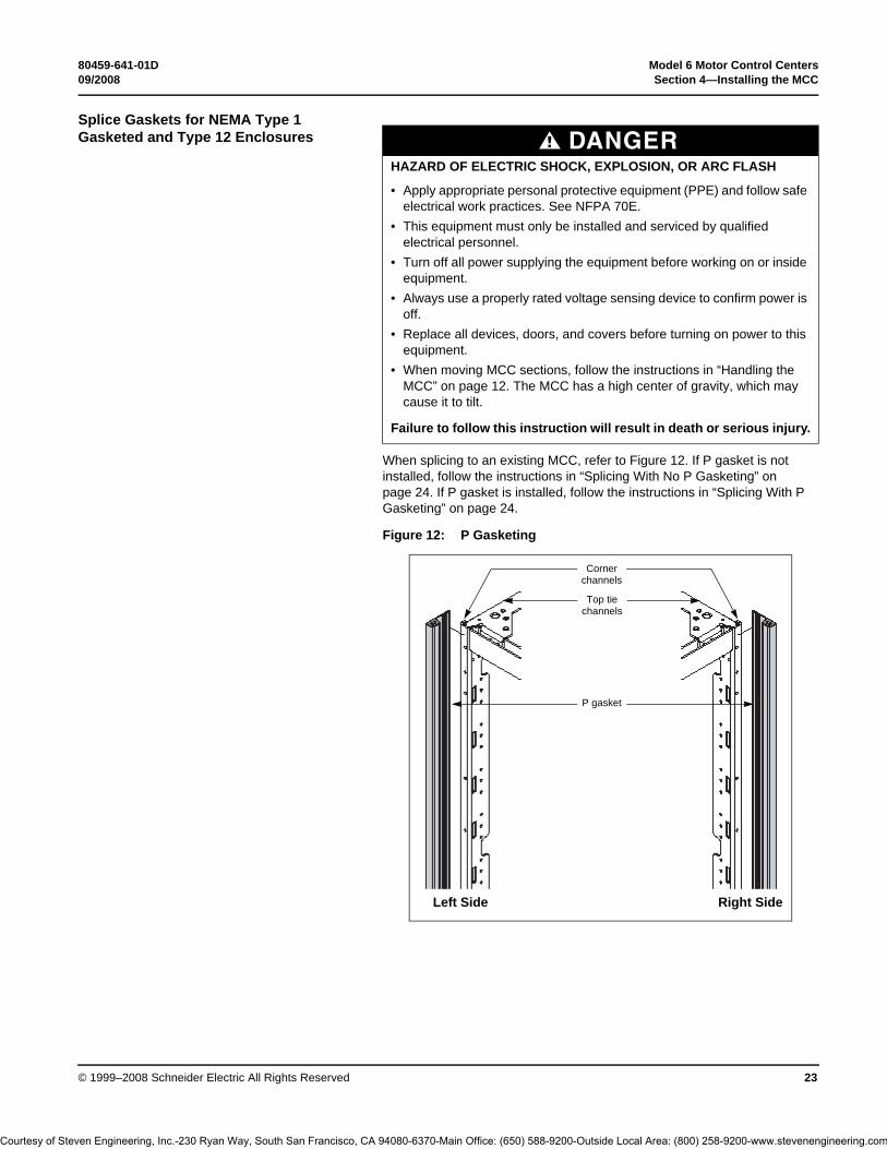
When splicing to an existing MCC, refer to Figure 12. If P gasket is not installed, follow the instructions in “Splicing With No P Gasketing” on page 24. If P gasket is installed, follow the instructions in “Splicing With P Gasketing” on page 24.
DANGERHAZARD OF ELECTRIC SHOCK, EXPLOSION, OR ARC FLASH
• Apply appropriate personal protective equipment (PPE) and follow safe electrical work practices. See NFPA 70E.
• This equipment must only be installed and serviced by qualified electrical personnel.
• Turn off all power supplying the equipment before working on or inside equipment.
• Always use a properly rated voltage sensing device to confirm power is off.
• Replace all devices, doors, and covers before turning on power to this equipment.
• When moving MCC sections, follow the instructions in “Handling the MCC” on page 12. The MCC has a high center of gravity, which may cause it to tilt.
Failure to follow this instruction will result in death or serious injury.
Figure 12: P Gasketing
Left Side Right Side
Corner channels
P gasket
Top tie channels
Courtesy of Steven Engineering, Inc.-230 Ryan Way, South San Francisco, CA 94080-6370-Main Office: (650) 588-9200-Outside Local Area: (800) 258-9200-www.stevenengineering.com

Model 6 Motor Control Centers 80459-641-01DSection 4—Installing the MCC 09/2008
© 1999–2008 Schneider Electric All Rights Reserved24
Splicing With No P Gasketing 1. Turn off all power supplying this equipment before working on or inside the equipment, and follow lockout/tagout procedures. Always use a properly rated voltage sensing device to confirm the power is off.
2. If splicing to an existing MCC, remove the end plate and any gasketing from the existing MCC.
3. Remove the white paper backing from the new gaskets (supplied by Schneider Electric) to expose the adhesive. This adhesive temporarily holds the gaskets in place while the sections are being positioned.
4. Apply P gaskets to the outside of the front and rear vertical corner channels (see Figure 12 on page 23). The gaskets should not extend above the top of the corner channels.
5. Apply flat gaskets to the outside of the top and bottom tie channels. The gaskets should not extend above the top of the tie channels.
6. Applying thumb pressure, firmly press the gaskets in place from top to bottom. Verify that the gaskets are flat along the entire length.
7. Join sections together following the appropriate steps in “Joining NEMA Type 1 / NEMA Type 1 Gasketed / NEMA Type 12 Sections” on page 16.
NOTE: When new sections will be added to left side of existing line-up, follow Steps 1, 2, and 7 only.
Splicing With P Gasketing Determine the location of the existing P gasket before splicing. If the P gasket is on the left (see Figure 12 on page 23), follow the instructions “Splice to Existing Left”. If the P gasket is on the right (see Figure 12 on page 23), follow the instructions “Splice to Existing Right”.
Splice to Existing Left 1. Turn off all power supplying this equipment before working on or inside the equipment, and follow lockout/tagout procedures. Always use a properly rated voltage sensing device to confirm the power is off.
2. Remove the end plate and all flat gaskets from the existing MCC. Leave the P gasket on the existing front corner channel in place.
3. Remove the factory installed flat gasket from the front corner channel of the new vertical section.
4. Join sections together following the appropriate steps in “Joining NEMA Type 1 / NEMA Type 1 Gasketed / NEMA Type 12 Sections” on page 16.
Splice to Existing Right 1. Turn off all power supplying this equipment before working on or inside the equipment, and follow lockout/tagout procedures. Always use a properly rated voltage sensing device to confirm the power is off.
2. Remove the end plate and all flat gaskets from the existing MCC. The P gasket on the existing front corner channel should be left in place.
3. Remove the white paper backing from the new gaskets (supplied by Schneider Electric) to expose the adhesive. This adhesive temporarily holds the gasket in place while the sections are being positioned.
4. Apply a P gasket to the outside of the rear vertical corner channel (see Figure 12 on page 23). The gasket should not extend above the top of the corner channel. Retain the extra P gasket for future use.
5. Apply flat gaskets to the outside of the top and bottom tie channels. The gaskets should not extend above the top of the tie channels.
6. Applying thumb pressure, firmly press the gasket in place from top to bottom. Ensure that the gasket is flat along the entire length.
7. Join sections together following the appropriate steps in “Joining NEMA Type 1 / NEMA Type 1 Gasketed / NEMA Type 12 Sections” on page 16.
Courtesy of Steven Engineering, Inc.-230 Ryan Way, South San Francisco, CA 94080-6370-Main Office: (650) 588-9200-Outside Local Area: (800) 258-9200-www.stevenengineering.com

80459-641-01D Model 6 Motor Control Centers09/2008 Section 4—Installing the MCC
© 1999–2008 Schneider Electric All Rights Reserved 25
Joining New Style NEMA Type 3R Enclosures to Old Style NEMA Type 3R Enclosures
This section provides instructions for joining new style NEMA Type 3R enclosures manufactured after February 1998 to old style NEMA Type 3R enclosures manufactured before February 1998 (the new MCC enclosure is 3 in. (76 mm) shorter than the existing MCC). Instructions for joining to the left or right of an existing MCC enclosure (as viewed from the front) are provided in this bulletin.
For all MCCs in NEMA Type 3R enclosures, the parts required for joining the enclosures are included in a kit. This kit is shipped with the MCC order and contains all the parts necessary to join the enclosures.
NOTE: All NEMA Type 3R sections manufactured after February 1998 measure approximately 93 in. (2362 mm) from the bottom of the section to the top of the deflector.
Joining to the Left Side of an Existing NEMA Type 3R MCC Enclosure.
1. Turn off all power supplying this equipment before working on or inside the equipment, and follow lockout/tagout procedures. Always use a properly rated voltage sensing device to confirm the power is off.
2. Remove the end deflector (see Figure 13) from the leftmost section of the existing MCC and the end deflector, if supplied, from the rightmost section of the MCC being added. Discard both end deflectors. Retain the hardware for installation of new parts.
3. Remove the back plate from the leftmost section of the existing MCC and also from the rightmost section of the MCC being added. Retain the back plates and mounting hardware for re-installation.
4. Remove the end plate (see Figure 13) from the leftmost section of the existing MCC and the end plate, if supplied, from the rightmost section of the MCC being added. Discard both end plates. Retain the hardware for installation of new parts.
5. Remove the insulating barrier (see Figure 14 on page 26) from the leftmost section of the existing MCC by punching out the rivets that are holding the barrier in place. Repeat this procedure for the barrier, if supplied, in the rightmost section of the MCC being added. Discard both barriers.NOTE: Ensure that rivet parts do not fall into the MCC.
DANGERHAZARD OF ELECTRIC SHOCK, EXPLOSION, OR ARC FLASH
• Apply appropriate personal protective equipment (PPE) and follow safe electrical work practices. See NFPA 70E.
• This equipment must only be installed and serviced by qualified electrical personnel.
• Turn off all power supplying this equipment before working on or inside equipment.
• Always use a properly rated voltage sensing device to confirm power is off.• Replace all devices, doors, and covers before turning on power to this
equipment.
Failure to follow this instruction will result in death or serious injury.
Figure 13: Removing the End Deflector
End deflector
End plate
Courtesy of Steven Engineering, Inc.-230 Ryan Way, South San Francisco, CA 94080-6370-Main Office: (650) 588-9200-Outside Local Area: (800) 258-9200-www.stevenengineering.com

Model 6 Motor Control Centers 80459-641-01DSection 4—Installing the MCC 09/2008
© 1999–2008 Schneider Electric All Rights Reserved26
6. Install the deflector bracket (see Figure 15) on the rightmost section of the MCC being added using two 8-32 Phillips head screws included in the kit. The same holes from which the rivets were removed will be used to mount the deflector bracket. Ensure that the top holes of the bracket align with the holes in the top plate of the enclosure.
7. Attach a left splice bracket (see Figure 15), 90 in. (2286 mm) long, to the front corner channel of the rightmost section of the MCC being added using six 1/4–20 screws contained in the kit. Ensure that the short flange is flush with the front of the corner channel and that the holes in the bracket line up with the holes in the corner channel.
Figure 14: Removing the Insulating Barrier
Figure 15: Installing the Deflector Bracket
Rivets
Insulating barrier
1/4–20 screws
Splice deflector
Section being added
Deflector bracket
8–32 screws
Right splice bracket [94 in. (2388 mm) long]
1/4–20 screws
Back bracket
Left splice bracket [90 in. (2286 mm) long]
10–32 flat Phillips head screws
Corner channel
Front vertical channel
Courtesy of Steven Engineering, Inc.-230 Ryan Way, South San Francisco, CA 94080-6370-Main Office: (650) 588-9200-Outside Local Area: (800) 258-9200-www.stevenengineering.com

80459-641-01D Model 6 Motor Control Centers09/2008 Section 4—Installing the MCC
© 1999–2008 Schneider Electric All Rights Reserved 27
8. Install a left splice bracket (see Figure 15 on page 26), 90 in. (2286 mm) long, to the rear corner channel of the rightmost section of the MCC being added using six 1/4–20 screws contained in the kit. Ensure that the short flange is flush with the back of the corner channel and that the holes in the bracket line up with the holes in the corner channel.
9. Attach a right splice bracket (see Figure 15), 94 in. (2388 mm) long, to the left splice bracket installed in Step 7 using six 10–32 flat Phillips head screws contained in the kit. Ensure that the short flange is behind the flange of the left splice bracket. The right splice bracket will extend below the left splice bracket by approximately 1 in. (25 mm) when properly installed.
10. Install a right splice bracket (see Figure 15), 94 in. (2388 mm) long, to the left splice bracket installed in Step 8 using six 10–32 flat Phillips head screws contained in the kit. Ensure that the short flange is in front of the flange of the left splice bracket. The right splice bracket will extend below the left splice bracket by approximately 1 in. (25 mm) when properly installed.
11. Position the structures that are to be spliced. Check that the fronts are flush to ensure proper alignment of all components.
12. Splice sections using the instructions in the Model 5 Instruction Bulletin (8998IM9101R5/92) if joining to a Model 5 MCC, or the instructions on page 23 of this instruction bulletin if joining to a Model 6 MCC.NOTE: When splicing the horizontal bus between the new and existing MCC sections, remove the splice bars contained in the leftmost section of the existing MCC. Discard the splice bars. Install the horizontal bus splice assembly provided in this kit using the instructions beginning on page 30 of this bulletin. Use the remaining six 1/4–20 hex head screws provided in the kit to splice the corner channels of the existing MCC to the right splice brackets installed in Steps 9 and 10.
13. Using the 10–32 hex head screws removed in Step 3, re-attach the back plate (see Figure 16) to the rightmost section of the new MCC. Install the back bracket (see Figure 15 on page 26) under the back plate using the left side holes of the back bracket. Ensure that the notch at the top of the back bracket is installed toward the new MCC section.
14. Using the 10–32 screws removed in Step 3, re-attach the back plate (see Figure 16) to the right section.
15. Install the splice deflector (see Figure 15 on page 26) to the rightmost section of the MCC being added. Use the five 1/4–20 screws supplied in the kit. Ensure that both top plate flanges are covered.
16. Install five of the 1/4–20 screws removed in Step 2 through the splice deflector and into the top plate of the leftmost section of the existing MCC.
17. Using the six 10–32 screws supplied in the kit, secure the right front vertical channel of the new NEMA Type 3R enclosure to the left front vertical channel of the existing NEMA Type 3R enclosure. NOTE: Install the screws through the clearance holes in the left front vertical channel of the existing MCC into the right front vertical channel of the new MCC.
18. Before energizing the equipment, replace all covers and barriers.
Figure 16: Re-attaching the Back Plates
Front
Rear
Left section back plate
Right section back plate
Multi-section back bracket Section corner
channels
Courtesy of Steven Engineering, Inc.-230 Ryan Way, South San Francisco, CA 94080-6370-Main Office: (650) 588-9200-Outside Local Area: (800) 258-9200-www.stevenengineering.com
Model 6 Motor Control Centers 80459-641-01DSection 4—Installing the MCC 09/2008
© 1999–2008 Schneider Electric All Rights Reserved28
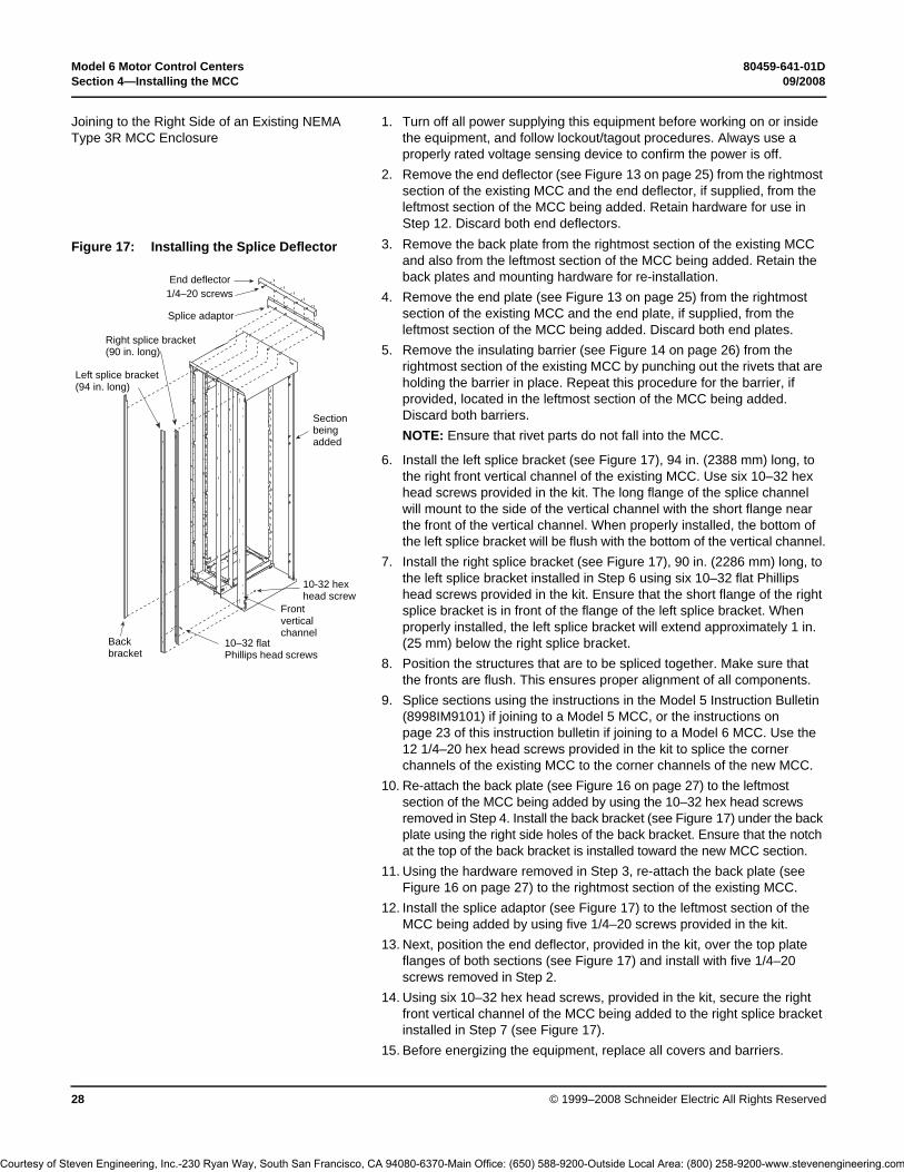
Joining to the Right Side of an Existing NEMA Type 3R MCC Enclosure
1. Turn off all power supplying this equipment before working on or inside the equipment, and follow lockout/tagout procedures. Always use a properly rated voltage sensing device to confirm the power is off.
2. Remove the end deflector (see Figure 13 on page 25) from the rightmost section of the existing MCC and the end deflector, if supplied, from the leftmost section of the MCC being added. Retain hardware for use in Step 12. Discard both end deflectors.
3. Remove the back plate from the rightmost section of the existing MCC and also from the leftmost section of the MCC being added. Retain the back plates and mounting hardware for re-installation.
4. Remove the end plate (see Figure 13 on page 25) from the rightmost section of the existing MCC and the end plate, if supplied, from the leftmost section of the MCC being added. Discard both end plates.
5. Remove the insulating barrier (see Figure 14 on page 26) from the rightmost section of the existing MCC by punching out the rivets that are holding the barrier in place. Repeat this procedure for the barrier, if provided, located in the leftmost section of the MCC being added. Discard both barriers.NOTE: Ensure that rivet parts do not fall into the MCC.
6. Install the left splice bracket (see Figure 17), 94 in. (2388 mm) long, to the right front vertical channel of the existing MCC. Use six 10–32 hex head screws provided in the kit. The long flange of the splice channel will mount to the side of the vertical channel with the short flange near the front of the vertical channel. When properly installed, the bottom of the left splice bracket will be flush with the bottom of the vertical channel.
7. Install the right splice bracket (see Figure 17), 90 in. (2286 mm) long, to the left splice bracket installed in Step 6 using six 10–32 flat Phillips head screws provided in the kit. Ensure that the short flange of the right splice bracket is in front of the flange of the left splice bracket. When properly installed, the left splice bracket will extend approximately 1 in. (25 mm) below the right splice bracket.
8. Position the structures that are to be spliced together. Make sure that the fronts are flush. This ensures proper alignment of all components.
9. Splice sections using the instructions in the Model 5 Instruction Bulletin (8998IM9101) if joining to a Model 5 MCC, or the instructions on page 23 of this instruction bulletin if joining to a Model 6 MCC. Use the 12 1/4–20 hex head screws provided in the kit to splice the corner channels of the existing MCC to the corner channels of the new MCC.
10. Re-attach the back plate (see Figure 16 on page 27) to the leftmost section of the MCC being added by using the 10–32 hex head screws removed in Step 4. Install the back bracket (see Figure 17) under the back plate using the right side holes of the back bracket. Ensure that the notch at the top of the back bracket is installed toward the new MCC section.
11. Using the hardware removed in Step 3, re-attach the back plate (see Figure 16 on page 27) to the rightmost section of the existing MCC.
12. Install the splice adaptor (see Figure 17) to the leftmost section of the MCC being added by using five 1/4–20 screws provided in the kit.
13. Next, position the end deflector, provided in the kit, over the top plate flanges of both sections (see Figure 17) and install with five 1/4–20 screws removed in Step 2.
14. Using six 10–32 hex head screws, provided in the kit, secure the right front vertical channel of the MCC being added to the right splice bracket installed in Step 7 (see Figure 17).
15. Before energizing the equipment, replace all covers and barriers.
Figure 17: Installing the Splice Deflector
End deflector1/4–20 screws
Splice adaptor
Right splice bracket(90 in. long)
Left splice bracket(94 in. long)
Section being added
10-32 hex head screw
Front vertical channel
10–32 flat Phillips head screws
Back bracket
Courtesy of Steven Engineering, Inc.-230 Ryan Way, South San Francisco, CA 94080-6370-Main Office: (650) 588-9200-Outside Local Area: (800) 258-9200-www.stevenengineering.com
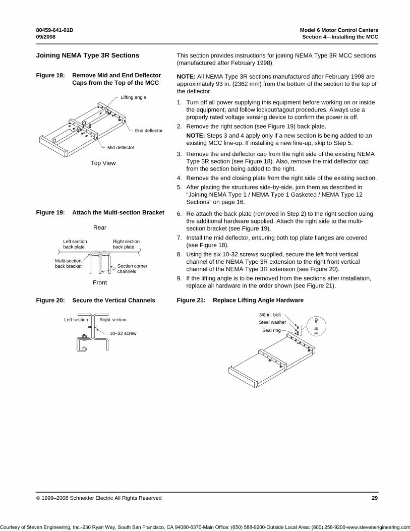
80459-641-01D Model 6 Motor Control Centers09/2008 Section 4—Installing the MCC
© 1999–2008 Schneider Electric All Rights Reserved 29
Joining NEMA Type 3R Sections This section provides instructions for joining NEMA Type 3R MCC sections (manufactured after February 1998).
NOTE: All NEMA Type 3R sections manufactured after February 1998 are approximately 93 in. (2362 mm) from the bottom of the section to the top of the deflector.
1. Turn off all power supplying this equipment before working on or inside the equipment, and follow lockout/tagout procedures. Always use a properly rated voltage sensing device to confirm the power is off.
2. Remove the right section (see Figure 19) back plate.NOTE: Steps 3 and 4 apply only if a new section is being added to an existing MCC line-up. If installing a new line-up, skip to Step 5.
3. Remove the end deflector cap from the right side of the existing NEMA Type 3R section (see Figure 18). Also, remove the mid deflector cap from the section being added to the right.
4. Remove the end closing plate from the right side of the existing section.5. After placing the structures side-by-side, join them as described in
“Joining NEMA Type 1 / NEMA Type 1 Gasketed / NEMA Type 12 Sections” on page 16.
6. Re-attach the back plate (removed in Step 2) to the right section using the additional hardware supplied. Attach the right side to the multi-section bracket (see Figure 19).
7. Install the mid deflector, ensuring both top plate flanges are covered (see Figure 18).
8. Using the six 10-32 screws supplied, secure the left front vertical channel of the NEMA Type 3R extension to the right front vertical channel of the NEMA Type 3R extension (see Figure 20).
9. If the lifting angle is to be removed from the sections after installation, replace all hardware in the order shown (see Figure 21).
Figure 18: Remove Mid and End Deflector Caps from the Top of the MCC
Top View
Lifting angle
End deflector
Mid deflector
Figure 19: Attach the Multi-section Bracket
Front
Rear
Left section back plate
Right section back plate
Multi-section back bracket Section corner
channels
Figure 20: Secure the Vertical Channels
Right section
10–32 screw
Left section
Figure 21: Replace Lifting Angle Hardware
3/8 in. boltSteel washer
Seal ring
Courtesy of Steven Engineering, Inc.-230 Ryan Way, South San Francisco, CA 94080-6370-Main Office: (650) 588-9200-Outside Local Area: (800) 258-9200-www.stevenengineering.com

Model 6 Motor Control Centers 80459-641-01DSection 4—Installing the MCC 09/2008
© 1999–2008 Schneider Electric All Rights Reserved30
Splicing Power Bus for NEMA Type 1 and Type 12 Enclosures
To splice the power bus, follow these steps:
1. Turn off all power supplying this equipment before working on or inside the equipment, and follow lockout/tagout procedures. Always use a properly rated voltage sensing device to confirm the power is off.
2. Remove the horizontal wireway covers and slide the horizontal bus barriers to gain access to the captive splice connectors (see Figure 22). See “Appendix A—Removal and Installation of Horizontal Bus Barrier Panels” for the steps for removing horizontal bus barriers.NOTE: On the integral splice assembly, located on the left side of each phase bus, the number of bus links is one greater than the number of horizontal bus bars. This creates a sandwich splice. The rear-most splice link contains the captive nuts.
3. Remove the two left bolts. Loosen, but do not remove, the two right bolts on the splice assembly (see Figure 23).NOTE: Do not remove the two right bolts from the splice assemblies. Doing so will permit spacers to fall from the splice assembly. If this occurs, re-assemble the splice bars and spacers (if applicable) in the proper order before continuing.
DANGERHAZARD OF ELECTRIC SHOCK, EXPLOSION, OR ARC FLASH
• Apply appropriate personal protective equipment (PPE) and follow safe electrical work practices. See NFPA 70E.
• This equipment must only be installed and serviced by qualified electrical personnel.
• Turn off all power supplying this equipment before working on or inside equipment.
• Always use a properly rated voltage sensing device to confirm power is off.
• Replace all devices, doors, and covers before turning on power to this equipment.
Failure to follow this instruction will result in death or serious injury.
Figure 22: Horizontal Wireway Covers and Bus Barriers Removed
Figure 23: Removing the Left Bolts and Loosening the Right Bolts on the Splice Assembly
Courtesy of Steven Engineering, Inc.-230 Ryan Way, South San Francisco, CA 94080-6370-Main Office: (650) 588-9200-Outside Local Area: (800) 258-9200-www.stevenengineering.com

80459-641-01D Model 6 Motor Control Centers09/2008 Section 4—Installing the MCC
© 1999–2008 Schneider Electric All Rights Reserved 31
4. Slide the splice assembly to the left until the two left holes are in line with the corresponding holes in the horizontal bus on the left section (see Figure 24).
5. Reinstall the two left bolts through the splice links and into the horizontal bus (see Figure 25); make sure the original conical washers are reinstalled with the concave side facing the splice bus (see Figure 26).
6. Torque all bolts on both ends to 31–32 lb-ft (41.87–43.22 N•m) (see Figure 27).
7. Repeat Steps 2–6 for all phases and for the neutral bus (if supplied).8. Before energizing the equipment, slide horizontal bus barriers into
closed position and replace all covers.
Figure 24: Aligning the Splice and Bus Holes
Figure 25: Inserting the Splice Bolts
Figure 26: Placing a Conical Washer Under the Bolt Head
Figure 27: Torquing the Bolts
Bolt head Conical
washer
SpacerBus bars
Courtesy of Steven Engineering, Inc.-230 Ryan Way, South San Francisco, CA 94080-6370-Main Office: (650) 588-9200-Outside Local Area: (800) 258-9200-www.stevenengineering.com

Model 6 Motor Control Centers 80459-641-01DSection 4—Installing the MCC 09/2008
© 1999–2008 Schneider Electric All Rights Reserved32
Splicing Power Bus in NEMA Type 3R Enclosures
This section describes how to splice the power bus of a NEMA Type 3R enclosure (manufactured after February 1998) to the power bus of another NEMA Type 3R section. Bus splicing material is not captive if the section is equipped with offset bus. Refer to bulletin 80453-649-01 for instructions for splicing offset power bus in NEMA Type 3R enclosures.
To splice power bus, follow these steps.
1. Turn off all power supplying this equipment before working on or inside the equipment, and follow lockout/tagout procedures. Always use a properly rated voltage sensing device to confirm the power is off.
2. Remove the horizontal wireway covers and slide the horizontal bus barriers to gain access to the captive splice connectors (see Figure 28). See “Appendix A—Removal and Installation of Horizontal Bus Barrier Panels” for the steps for removing horizontal bus barriers.NOTE: On the integral splice assembly, located on the left side of each phase bus, the number of bus links is one greater than the number of horizontal bus bars. This creates a sandwich splice. The rear-most splice link contains the captive nuts.
3. Remove the two left bolts from each splice assembly. Then loosen, but do not remove, the two right bolts of each splice assembly (see Figure 29).NOTE: Do not remove the two right bolts or the center bolt (if applicable) from the splice assemblies. Doing so will permit spacers to fall from the splice assembly. If this occurs, re-assemble the splice bars and spacers (if applicable) in the proper order before continuing.
4. Slide the splice assembly to the left until the two left holes are in line with the corresponding holes in the horizontal bus in the left section (see Figure 30).
DANGERHAZARD OF ELECTRIC SHOCK, EXPLOSION, OR ARC FLASH
• Apply appropriate personal protective equipment (PPE) and follow safe electrical work practices. See NFPA 70E.
• This equipment must only be installed and serviced by qualified electrical personnel.
• Turn off all power supplying this equipment before working on or inside equipment.
• Always use a properly rated voltage sensing device to confirm power is off.• Replace all devices, doors, and covers before turning on power to this
equipment.
Failure to follow this instruction will result in death or serious injury.
Figure 28: Wireway Covers Removed and Horizontal Bus Barriers Open
Figure 29: Loosen Bolts
Figure 30: Slide the Splice Assembly to the Left
Courtesy of Steven Engineering, Inc.-230 Ryan Way, South San Francisco, CA 94080-6370-Main Office: (650) 588-9200-Outside Local Area: (800) 258-9200-www.stevenengineering.com

80459-641-01D Model 6 Motor Control Centers09/2008 Section 4—Installing the MCC
© 1999–2008 Schneider Electric All Rights Reserved 33
5. Re-install the two left bolts through the splice assembly and into the horizontal bus (see Figure 31). Make sure the original conical washers are re-installed with the concave side facing the splice bus (see Figure 32).
6. Torque the bolts to 31–32 lb-ft (41.87–43.22 N•m). See Figure 33.
7. Repeat Steps 2–6 for all phases and the neutral bus (if supplied).8. Before energizing the equipment, replace all covers and barriers.
Ground Bus Splicing for NEMA Type 1, Type 12, and Type 3R
Figure 31: Inserting the Splice Bolts
Figure 32: Place a Conical Washer Under the Bolt Head
Figure 33: Torque All Bolts
Bolt head Conical
washer
SpacerBus bars
Figure 34: Ground Splice Bar as ShippedDANGER
HAZARD OF ELECTRIC SHOCK, EXPLOSION, OR ARC FLASH
• Apply appropriate personal protective equipment (PPE) and follow safe electrical work practices. See NFPA 70E.
• This equipment must only be installed and serviced by qualified electrical personnel.
• Turn off all power supplying this equipment before working on or inside equipment.
• Always use a properly rated voltage sensing device to confirm power is off.• Replace all devices, doors, and covers before turning on power to this
equipment.
Failure to follow this instruction will result in death or serious injury.
Courtesy of Steven Engineering, Inc.-230 Ryan Way, South San Francisco, CA 94080-6370-Main Office: (650) 588-9200-Outside Local Area: (800) 258-9200-www.stevenengineering.com
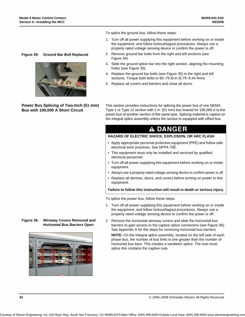
Model 6 Motor Control Centers 80459-641-01DSection 4—Installing the MCC 09/2008
© 1999–2008 Schneider Electric All Rights Reserved34
To splice the ground bus, follow these steps:
1. Turn off all power supplying this equipment before working on or inside the equipment, and follow lockout/tagout procedures. Always use a properly rated voltage sensing device to confirm the power is off.
2. Remove ground bar bolts from the right and left sections (see Figure 34).
3. Slide the ground splice bar into the right section, aligning the mounting holes (see Figure 35).
4. Replace the ground bar bolts (see Figure 35) in the right and left sections. Torque both bolts to 60–75 lb-in (6.75–8.44 N•m).
5. Replace all covers and barriers and close all doors.
Power Bus Splicing of Two-Inch (51 mm) Bus with 100,000 A Short Circuit
This section provides instructions for splicing the power bus of one NEMA Type 1 or Type 12 section with 2 in. (51 mm) bus braced for 100,000 A to the power bus of another section of the same type. Splicing material is captive on the integral splice assembly unless the section is equipped with offset bus.
To splice the power bus, follow these steps:
1. Turn off all power supplying this equipment before working on or inside the equipment, and follow lockout/tagout procedures. Always use a properly rated voltage sensing device to confirm the power is off.
2. Remove the horizontal wireway covers and slide the horizontal bus barriers to gain access to the captive splice connectors (see Figure 36). See Appendix A for the steps for removing horizontal bus barriers.NOTE: On the integral splice assembly, located on the left side of each phase bus, the number of bus links is one greater than the number of horizontal bus bars. This creates a sandwich splice. The rear-most splice link contains the captive nuts.
Figure 35: Ground Bar Bolt Replaced
DANGERHAZARD OF ELECTRIC SHOCK, EXPLOSION, OR ARC FLASH
• Apply appropriate personal protective equipment (PPE) and follow safe electrical work practices. See NFPA 70E.
• This equipment must only be installed and serviced by qualified electrical personnel.
• Turn off all power supplying this equipment before working on or inside equipment.
• Always use a properly rated voltage sensing device to confirm power is off.• Replace all devices, doors, and covers before turning on power to this
equipment.
Failure to follow this instruction will result in death or serious injury.
Figure 36: Wireway Covers Removed and Horizontal Bus Barriers Open
Courtesy of Steven Engineering, Inc.-230 Ryan Way, South San Francisco, CA 94080-6370-Main Office: (650) 588-9200-Outside Local Area: (800) 258-9200-www.stevenengineering.com

80459-641-01D Model 6 Motor Control Centers09/2008 Section 4—Installing the MCC
© 1999–2008 Schneider Electric All Rights Reserved 35
3. Remove all four bolts from each splice assembly (see Figure 37).4. Slide the splice assembly to the left until the two left holes are in line with the
corresponding holes in the horizontal bus on the left section (see Figure 38).
5. Reinstall all four bolts through the splice assembly and into the horizontal bus (see Figure 39); make sure the original conical washers are reinstalled with the concave side facing the splice bus (see Figure 40).
6. Torque all bolts on both ends to 31–32 lb-ft (41.87–43.22 N m). See Figure 41.
7. Repeat Steps 2–6 for all phases and the neutral bus (if supplied).8. Before energizing the equipment, replace all covers and barriers.
Figure 37: Removing the Bolts from the Splice Assembly
Figure 38: Aligning the Splice and Bus Holes
Figure 39: Inserting the Splice Bolts
Figure 40: Place a Conical Washer Under the Bolt Head
Figure 41: Torque All Bolts
Bolt head Conical
washer
SpacerBus bars
Courtesy of Steven Engineering, Inc.-230 Ryan Way, South San Francisco, CA 94080-6370-Main Office: (650) 588-9200-Outside Local Area: (800) 258-9200-www.stevenengineering.com
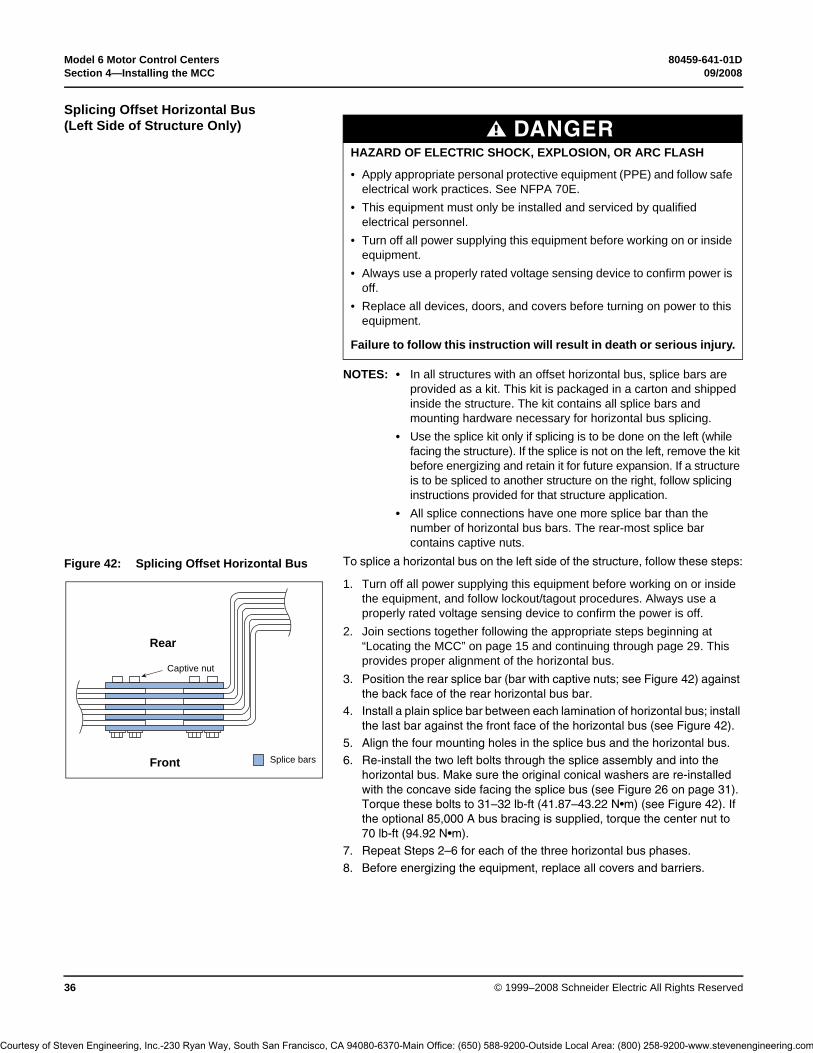
Model 6 Motor Control Centers 80459-641-01DSection 4—Installing the MCC 09/2008
© 1999–2008 Schneider Electric All Rights Reserved36
Splicing Offset Horizontal Bus (Left Side of Structure Only)
NOTES: • In all structures with an offset horizontal bus, splice bars are provided as a kit. This kit is packaged in a carton and shipped inside the structure. The kit contains all splice bars and mounting hardware necessary for horizontal bus splicing.
• Use the splice kit only if splicing is to be done on the left (while facing the structure). If the splice is not on the left, remove the kit before energizing and retain it for future expansion. If a structure is to be spliced to another structure on the right, follow splicing instructions provided for that structure application.
• All splice connections have one more splice bar than the number of horizontal bus bars. The rear-most splice bar contains captive nuts.
To splice a horizontal bus on the left side of the structure, follow these steps:
1. Turn off all power supplying this equipment before working on or inside the equipment, and follow lockout/tagout procedures. Always use a properly rated voltage sensing device to confirm the power is off.
2. Join sections together following the appropriate steps beginning at “Locating the MCC” on page 15 and continuing through page 29. This provides proper alignment of the horizontal bus.
3. Position the rear splice bar (bar with captive nuts; see Figure 42) against the back face of the rear horizontal bus bar.
4. Install a plain splice bar between each lamination of horizontal bus; install the last bar against the front face of the horizontal bus (see Figure 42).
5. Align the four mounting holes in the splice bus and the horizontal bus.
6. Re-install the two left bolts through the splice assembly and into the horizontal bus. Make sure the original conical washers are re-installed with the concave side facing the splice bus (see Figure 26 on page 31). Torque these bolts to 31–32 lb-ft (41.87–43.22 N•m) (see Figure 42). If the optional 85,000 A bus bracing is supplied, torque the center nut to 70 lb-ft (94.92 N•m).
7. Repeat Steps 2–6 for each of the three horizontal bus phases.
8. Before energizing the equipment, replace all covers and barriers.
DANGERHAZARD OF ELECTRIC SHOCK, EXPLOSION, OR ARC FLASH
• Apply appropriate personal protective equipment (PPE) and follow safe electrical work practices. See NFPA 70E.
• This equipment must only be installed and serviced by qualified electrical personnel.
• Turn off all power supplying this equipment before working on or inside equipment.
• Always use a properly rated voltage sensing device to confirm power is off.
• Replace all devices, doors, and covers before turning on power to this equipment.
Failure to follow this instruction will result in death or serious injury.
Figure 42: Splicing Offset Horizontal Bus
Front
Rear
Captive nut
Splice bars
Courtesy of Steven Engineering, Inc.-230 Ryan Way, South San Francisco, CA 94080-6370-Main Office: (650) 588-9200-Outside Local Area: (800) 258-9200-www.stevenengineering.com

80459-641-01D Model 6 Motor Control Centers09/2008 Section 4—Installing the MCC
© 1999–2008 Schneider Electric All Rights Reserved 37
Conductor Entry
Conduit entry space is provided at the top and bottom of the MCC structure. The top plates (and closing plates in bottom, if present) are removable for convenience in wiring and cutting conduit openings). A hinged door allows access to the main lug, main circuit breaker, or main switch compartment. In some cases, the horizontal wire trough cover must be removed.
Pullboxes are available if additional wiring space is required.
Cable connection torque values are listed in Table 3 and Table 4 on page 42.
Vent Hood Installation for MCCs with 2500 A Horizontal Bus
This section contains instructions for installing a vent hood over the top plate vents on a motor control center (MCC) with 2500 A horizontal bus.
NOTES: • Do not install the vent hood until the MCC is in its final location.• Retain all hardware.
DANGERHAZARD OF ELECTRIC SHOCK, EXPLOSION, OR ARC FLASH
• Apply appropriate personal protective equipment (PPE) and follow safe electrical work practices. See NFPA 70E.
• This equipment must only be installed and serviced by qualified electrical personnel.
• Turn off all power supplying this equipment before working on or inside equipment.
• Always use a properly rated voltage sensing device to confirm power is off.
• Replace all devices, doors, and covers before turning on power to this equipment.
Failure to follow this instruction will result in death or serious injury.
DANGERHAZARD OF ELECTRIC SHOCK, EXPLOSION, OR ARC FLASH
• Apply appropriate personal protective equipment (PPE) and follow safe electrical work practices. See NFPA 70E.
• This equipment must only be installed and serviced by qualified electrical personnel.
• Turn off all power supplying this equipment before working on or inside equipment.
• Always use a properly rated voltage sensing device to confirm power is off.
• Replace all devices, doors, and covers before turning on power to this equipment.
• Do not drill or cut in the top area of the motor control center.• Avoid contaminating the motor control center with dust or debris.• DO NOT lift the cabinet by the vent hood or by attaching lifting angles to the
vent hood.
Failure to follow this instruction will result in death or serious injury.
Courtesy of Steven Engineering, Inc.-230 Ryan Way, South San Francisco, CA 94080-6370-Main Office: (650) 588-9200-Outside Local Area: (800) 258-9200-www.stevenengineering.com

Model 6 Motor Control Centers 80459-641-01DSection 4—Installing the MCC 09/2008
© 1999–2008 Schneider Electric All Rights Reserved38
1. Turn off all power supplying this equipment before working on or inside the equipment, and follow lockout/tagout procedures. Always use a properly rated voltage sensing device to confirm the power is off.
2. Remove the 3/8-in. (9.525 mm) bolts, washers, and the lifting angle (see Figure 43).
3. Remove the two 10-32 screws that secure the vent hood and closing plate to the top of the cabinet (see Figure 43).
4. Once the vent hood is removed, secure the top closing plate by reinstalling the 10-32 screws removed in Step 3 (see Figure 44).
5. Position the vent hood on the top of the cabinet as shown.6. Secure the vent hood in place using the two 3/8-in. (9.525 mm)
bolts and washers removed in Step 2. Torque the bolts to 28–33 lb-in (3.164–3.729 N•m).
Figure 43: Remove the Hardware
Figure 44: Reposition and Attach the Vent Hood
3/8-in. (9.525 mm) bolt and washer
Lifting angle
10-32 screw
Vent hood
Top closing plate
Vent hood
Courtesy of Steven Engineering, Inc.-230 Ryan Way, South San Francisco, CA 94080-6370-Main Office: (650) 588-9200-Outside Local Area: (800) 258-9200-www.stevenengineering.com

80459-641-01D Model 6 Motor Control Centers09/2008 Section 4—Installing the MCC
© 1999–2008 Schneider Electric All Rights Reserved 39
Vented Pullbox Installation for MCCs with 2500 A Horizontal Bus
This section contains instructions for installing a vented pullbox on a motor control center with 2500 A horizontal bus. Pullboxes are either 12 or 18 in. (304.8 or 457.2 mm) high and mount on the top of the MCC.
NOTES: • Do not install the pullbox until the MCC is in its final location.• Retain all hardware.
1. Turn off all power supplying this equipment before working on or inside the equipment, and follow lockout/tagout procedures. Always use a properly rated voltage sensing device to confirm power is off.
2. Remove the 3/8-in. (9.525 mm) bolts, washers, and the lifting angle (see Figure 45).
3. Remove the two 10-32 screws that secure the top closing plate to the top of the cabinet (see Figure 45).
4. Remove the top closing plate from the structure.5. Remove the front panel from the pullbox. Position the pullbox on top of
the cabinet as shown in Figure 46.6. Install the two 3/8-in. (9.525 mm) bolts and washers that were removed in
Step 2. Place them through the pullbox lower side channels and into the top of the cabinet. Torque the bolts to 28–33 lb-in (3.164–3.729 N•m).
7. Re-install the pullbox front panel removed in Step 5 and the top closing plate removed in Step 4 (see Figure 46).
DANGERHAZARD OF ELECTRIC SHOCK, EXPLOSION, OR ARC FLASH
• Apply appropriate personal protective equipment (PPE) and follow safe electrical work practices. See NFPA 70E.
• This equipment must only be installed and serviced by qualified electrical personnel.
• Turn off all power supplying this equipment before working on or inside it.• Always use a properly rated voltage sensing device to confirm power is off.• Replace all devices, doors, and covers before turning on power to this
equipment.• Do not drill or cut in the top area of the motor control center.• Avoid contaminating the motor control center with dust or debris.• DO NOT lift the cabinet by the vent hood or by attaching lifting angles to the
vent hood.
Failure to follow this instruction will result in death or serious injury.
Figure 45: Remove the Hardware
3/8-in. (9.525 mm) bolt and washer
Lifting angle
10-32 screw
Top closing plate
Figure 46: Install the Pullbox
Front panel
Pullbox
Top closing plate
Courtesy of Steven Engineering, Inc.-230 Ryan Way, South San Francisco, CA 94080-6370-Main Office: (650) 588-9200-Outside Local Area: (800) 258-9200-www.stevenengineering.com

Model 6 Motor Control Centers 80459-641-01DSection 4—Installing the MCC 09/2008
© 1999–2008 Schneider Electric All Rights Reserved40
Load and Control Wiring The top and bottom horizontal wire troughs and the vertical wire trough are convenient areas to run incoming line, load, and control wires (see Figure 47). Openings between sections permit wire to pass from one section into the next for interwiring.
Control and power wires are routed to each unit via the vertical wire trough. When supplied, grommeted wire ports must be opened to route wire to the unit. The H-shaped cut pattern is pre-scored for easy opening. Using a small knife, cut through the center tabs and complete the H-shaped slice (see Figure 48). When cutting, be sure not to damage the wires located near the grommet.
Pull-apart control terminals (see Figure 49) are mounted on a 35 mm DIN-rail located adjacent to the wiring ports toward the front of the unit. Terminate field control wiring on the removable portion of the block.
Figure 47: Wiring in the Top Horizontal Wire Trough
Figure 48: Vertical Wire Trough Grommet
Figure 49: Pull-apart Type Terminal Blocks
Courtesy of Steven Engineering, Inc.-230 Ryan Way, South San Francisco, CA 94080-6370-Main Office: (650) 588-9200-Outside Local Area: (800) 258-9200-www.stevenengineering.com
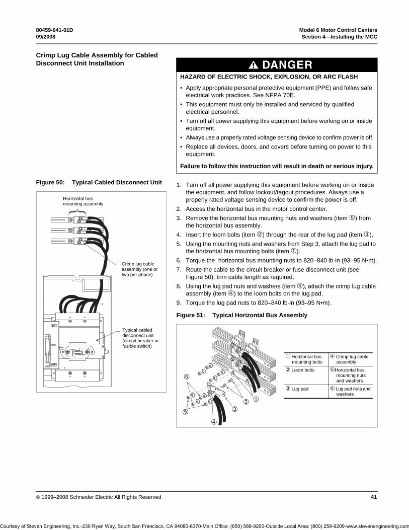
80459-641-01D Model 6 Motor Control Centers09/2008 Section 4—Installing the MCC
© 1999–2008 Schneider Electric All Rights Reserved 41
Crimp Lug Cable Assembly for Cabled Disconnect Unit Installation
1. Turn off all power supplying this equipment before working on or inside the equipment, and follow lockout/tagout procedures. Always use a properly rated voltage sensing device to confirm the power is off.
2. Access the horizontal bus in the motor control center.3. Remove the horizontal bus mounting nuts and washers (item ➄) from
the horizontal bus assembly.4. Insert the loom bolts (item ➁) through the rear of the lug pad (item ➂). 5. Using the mounting nuts and washers from Step 3, attach the lug pad to
the horizontal bus mounting bolts (item ➀).6. Torque the horizontal bus mounting nuts to 820–840 lb-in (93–95 N•m).7. Route the cable to the circuit breaker or fuse disconnect unit (see
Figure 50); trim cable length as required.8. Using the lug pad nuts and washers (item ➅), attach the crimp lug cable
assembly (item ➃) to the loom bolts on the lug pad.9. Torque the lug pad nuts to 820–840 lb-in (93–95 N•m).
DANGERHAZARD OF ELECTRIC SHOCK, EXPLOSION, OR ARC FLASH
• Apply appropriate personal protective equipment (PPE) and follow safe electrical work practices. See NFPA 70E.
• This equipment must only be installed and serviced by qualified electrical personnel.
• Turn off all power supplying this equipment before working on or inside equipment.
• Always use a properly rated voltage sensing device to confirm power is off.• Replace all devices, doors, and covers before turning on power to this
equipment.
Failure to follow this instruction will result in death or serious injury.
Figure 50: Typical Cabled Disconnect Unit
Typical cabled disconnect unit (circuit breaker or fusible switch)
Crimp lug cable assembly (one or two per phase)
Horizontal bus mounting assembly
Figure 51: Typical Horizontal Bus Assembly
➀➁➂
➃
➅
➄
➀ Horizontal bus mounting bolts
➃ Crimp lug cable assembly
➁ Loom bolts ➄Horizontal bus mounting nuts and washers
➂ Lug pad ➅ Lug pad nuts and washers
Courtesy of Steven Engineering, Inc.-230 Ryan Way, South San Francisco, CA 94080-6370-Main Office: (650) 588-9200-Outside Local Area: (800) 258-9200-www.stevenengineering.com

Model 6 Motor Control Centers 80459-641-01DSection 4—Installing the MCC 09/2008
© 1999–2008 Schneider Electric All Rights Reserved42
Cable Connection Torque Values The following tables provide main disconnect and branch feeder torque values, which apply to both aluminum and copper conductors.
Component Instructional Information Component manuals for devices such as adjustable frequency drive controllers, solid state reduced voltage starters, and programmable logic controllers are included with the MCC instruction information packet.
Thermal overload selection data is listed on the inside of the vertical wire trough door of each section. This information is also listed in this bulletin; see “Thermal Overload Unit Selection” beginning on page 94. Select proper thermal overloads from the applicable starter size tables.
Figure 52: Main Lug Compartment Torque Connection
Table 3: Connection Torque Values for Main Lug Compartments (see Figure 52)
Socket Size Across Flat Torque
3/8 in. 375 lb-in (42.4 N•m)
1/2 in. 600 lb-in (67.8 N•m)
Table 4: Connection Torque Values for Main and Branch Feeders
Frame Size Ampere Rating Torque
H 15–30 A35–150 A
50 lb-in (5.6 N•m)120 lb-in (13.6 N•m)
J 150–250 A 225 lb-in (25.4 N•m)
FA 15–30 A35–100 A
35 lb-in (3.9 N•m)80 lb-in (9.0 N•m)
FC 20–30 A40–100 A
35 lb-in (4.0 N•m)65 lb-in (7.3 N•m)
KA 70–250 A 250 lb-in (28.2 N•m)
KC 110–250 A 250 lb-in (28.2 N•m)
LA/LH 125–400 A 200 lb-in (22.6 N•m)
LC/LI/LE/LX/LXI 300-600 A 300 lb-in (33.9 N•m)
MA/MH/ME/MX 200–400 A450–1000 A
300 lb-in (33.9 N•m)300 lb-in (33.9 N•m)
NT 400-1200 A 600 lb-in (67.8 N•m)
NW (top entry) 400-2500 A 600 lb-in (67.8 N•m)
PA/PH/PE/PX 800–2000 A 500 lb-in (56.5 N•m)
MJ/MG 300-800 A 450 lb-in (50.8 N•m)
PJ/PK/PG/PL 250-1200 A 450 lb-in (50.8 N•m)
RJ/RK/RG/RL 600-2500 A 500 lb-in (56.5 N•m)
Courtesy of Steven Engineering, Inc.-230 Ryan Way, South San Francisco, CA 94080-6370-Main Office: (650) 588-9200-Outside Local Area: (800) 258-9200-www.stevenengineering.com

80459-641-01D Model 6 Motor Control Centers09/2008 Section 4—Installing the MCC
© 1999–2008 Schneider Electric All Rights Reserved 43
Modifying Fuse Clip Locations
Install 30 and 60 A fuse bases for the proper fuse size and class and maximum voltage in Size 1 and 2 starter units. The base pan of the disconnect switch has five sets of mounting holes for this purpose. The lower fuse base is installed in the proper mounting holes at the factory (see Figure 53). Additional clips and bases may be required if changing fuse class.
Turn off all power supplying this equipment and follow lockout/tagout procedures before working on or inside equipment. Always use a properly rated voltage sensing device to confirm the power is off.
NOTE: For Form II Class C fuse spacing, contact your Schneider Canada representative.
DANGERHAZARD OF ELECTRIC SHOCK, EXPLOSION, OR ARC FLASH
• Apply appropriate personal protective equipment (PPE) and follow safe electrical work practices. See NFPA 70E.
• This equipment must only be installed and serviced by qualified electrical personnel.
• Never operate energized switch with door open.• Turn off switch before removing or installing fuses or making load side
connections.• Always use a properly rated voltage sensing device at all line and load
fuse clips to confirm switch is off.• Turn off all power supplying switch before doing any other work on or
inside switch.• Do not use renewable link fuses in fused switches.
Failure to follow this instruction will result in death or serious injury.
Figure 53: Size 1 and 2 Fuse Clip Locations
30/60 A Class J30 A Class H/R 250 V60 A Class H/R 250 V
30 A Class H/R 600 V60 A Class H/R 600 V
Courtesy of Steven Engineering, Inc.-230 Ryan Way, South San Francisco, CA 94080-6370-Main Office: (650) 588-9200-Outside Local Area: (800) 258-9200-www.stevenengineering.com

Model 6 Motor Control Centers 80459-641-01DSection 5—Operation 09/2008
© 1999–2008 Schneider Electric All Rights Reserved44
Section 5—Operation Included in this section are the pre-operation checklist and energizing procedures.
Pre-operation Checklist To ensure proper operation of the MCC, check the items listed below before energizing the MCC:
❏ Complete the maintenance procedures beginning on page 46 and continuing up to “Insulation Test” on page 56. This initial maintenance is necessary to detect any shipping damage or loose connections. Do not energize the MCC until initial maintenance is complete. NOTE: The following maintenance procedures are not necessary before energizing the MCC for the first time: Control Unit Removal, Stab Assemblies, Starter Contacts and Barriers/Insulators.
❏ Perform an insulation test on the MCC (see “Insulation Test” on page 56).
❏ If the MCC is equipped with ground fault protection, properly adjust and test the ground fault protective device before energizing.
❏ Remove all blocks or other temporary holding means from the electrical devices.
❏ Remove any secondary shunt bars from the current transformers. Do not operate a current transformer with its secondary open-circuited.
❏ Manually exercise all switches, circuit breakers, and other operator mechanisms to ensure that they are properly aligned and operate freely.
❏ Electrically exercise all electrically-operated switches, circuit breakers and other mechanisms (but not under load) to ensure that the devices operate properly. An auxiliary source of control power may be required.
❏ Verify proper interval and contact operation of the timers.❏ Verify that proper overload units are installed by checking the overload
selection tables against motor full load current. Motor Logic, TeSys® T, and IEC overload relays (if supplied) do not require thermal units, but are set at the lowest setting at the factory.
❏ Verify that all load and remote control connections have been made and that they agree with the wiring diagrams provided.
❏ Verify that all ground connections are made properly.❏ Install the covers and close the doors; ensure that all are properly
tightened; verify that all mechanism interlocks function.
Figure 54: Pre-operation Checkv
Courtesy of Steven Engineering, Inc.-230 Ryan Way, South San Francisco, CA 94080-6370-Main Office: (650) 588-9200-Outside Local Area: (800) 258-9200-www.stevenengineering.com

80459-641-01D Model 6 Motor Control Centers09/2008 Section 5—Operation
© 1999–2008 Schneider Electric All Rights Reserved 45
Energizing the MCC
To energize the MCC:
1. Review the “Pre-operation Checklist” on page 44 before energizing.2. Turn off all downstream loads, including distribution equipment and
other devices that are remote from the MCC.3. Verify that all barriers, doors, and covers are closed before energizing
the equipment.4. Energize the equipment in sequence, starting with the main devices, the
feeder devices next, and then the motor starter devices.5. With all barriers in place and all unit doors closed and latched, turn on
the devices with a firm, positive motion.6. After all disconnect devices are closed, loads such as lighting circuits,
starters, contactors, heaters, and motors may be energized.
DANGERHAZARD OF ELECTRIC SHOCK, EXPLOSION, OR ARC FLASH
• Apply appropriate personal protective equipment (PPE) and follow safe electrical work practices. See NFPA 70E.
• This equipment must only be installed and serviced by qualified electrical personnel.
• Turn off all power supplying this equipment before working on or inside equipment.
• Always use a properly rated voltage sensing device to confirm power is off.
• Replace all devices, doors, and covers before turning on power to this equipment.
• Review the “Pre-operation Checklist” on page 44, ensuring that all items check out.
Failure to follow this instruction will result in death or serious injury.
Courtesy of Steven Engineering, Inc.-230 Ryan Way, South San Francisco, CA 94080-6370-Main Office: (650) 588-9200-Outside Local Area: (800) 258-9200-www.stevenengineering.com

Model 6 Motor Control Centers 80459-641-01DSection 6—Maintaining the MCC 09/2008
© 1999–2008 Schneider Electric All Rights Reserved46
Section 6—Maintaining the MCC
Before energizing any new MCC equipment, perform the maintenance described in this section. Perform regular maintenance at least annually, or more frequently if indicated by service conditions and your established maintenance policy. Also perform maintenance following any service interruption, electrical fault, or unusual occurrence.
Examining the Enclosure Examine the interior and exterior of the MCC for moisture, oil, or other foreign material. Eliminate all foreign material and clean the MCC.
Clean the interior and exterior of the MCC with a vacuum cleaner. (Do not use compressed air; it will redistribute contaminants to other surfaces.) Check the enclosure for damage that might reduce electrical clearances.
Examine the finish of the enclosure. Touch up the paint if necessary. Replace any badly corroded or damaged enclosure parts.
Maintaining Bus Bars and Incoming Line Compartments
Perform maintenance of bus and incoming line lug connections at least annually, or more frequently if indicated by service conditions and your established maintenance policy. Follow the steps below at the time of installation to locate and tighten any connections that may have loosened during shipment and handling:
1. Turn off all power supplying this equipment before working on or inside the equipment, and follow lockout/tagout procedures. Always use a properly rated voltage sensing device to confirm power is off.
2. Remove the top andbottom horizontal wire trough covers in each section.3. Expose the bus and bus connections by removing the two-piece bus
barrier in each section.4. Examine all bus bars and connectors. Replace any parts that are badly
discolored, corroded, or pitted. Also replace parts subjected to excessive temperatures.
5. Verify that all bolts at the bus connection points indicated by a hexagon in Figure 55 are in place and properly tightened. Although one specific type of compartment or bus is shown in Figure 55, perform this maintenance on all bolted connections. See Table 5 for torque values.
DANGERHAZARD OF ELECTRIC SHOCK, EXPLOSION, OR ARC FLASH
• Apply appropriate personal protective equipment (PPE) and follow safe electrical work practices. See NFPA 70E.
• This equipment must only be installed and serviced by qualified electrical personnel.
• Turn off all power supplying this equipment before working on or inside equipment.
• Always use a properly rated voltage sensing device to confirm power is off.
• Replace all devices, doors, and covers before turning on power to this equipment.
Failure to follow this instruction will result in death or serious injury.
CAUTIONHAZARD OF EQUIPMENT DAMAGE
• Never brush or use sandpaper on the bus; doing so will remove plating and cause oxidation. Use a cleaning fluid approved for such use. Do not use cleaning fluid on insulators.
• Do not attempt to clean bus bars or connectors that are damaged in any way. Replace them with new parts.
Failure to follow this instruction can result in equipment damage.
Table 5: Bus Connection Torque Values
Bolted Connection Location Torque Range
Horizontal bus (all locations) 68–70 lb-ft (92.29–94.54 N•m)
Splice bars—0.375 in. diameter bolts 31–32 lb-ft (41.64–43.33 N•m)
Horizontal ground bus (all locations) 5–6 lb-ft (6.75–8.44 N•m)
Figure 55: Typical Bus Connection Points
AØ
AØ
BØ
CØ
AØ
BØ
CØ
BØ CØ
Typical Top-Located 600 A or 800 A Main Lug Compartment
Typical Splice Bar Connection Typical Horizontal Bus Connection
Splice bar
Courtesy of Steven Engineering, Inc.-230 Ryan Way, South San Francisco, CA 94080-6370-Main Office: (650) 588-9200-Outside Local Area: (800) 258-9200-www.stevenengineering.com

80459-641-01D Model 6 Motor Control Centers09/2008 Section 6—Maintaining the MCC
© 1999–2008 Schneider Electric All Rights Reserved 47
6. Verify that all main lug, circuit breaker, or fusible switch set screws holding incoming conductors in main lugs are in place and properly tightened (see Figure 56). Use a torque wrench and a 3/8 in. allen bit to torque the lug set screws to the appropriate value (see “Cable Connection Torque Values” on page 42).
7. Inspect all insulators, braces, and barriers; replace any that show signs of arcing damage, tracking, excessive heat, or cracking.
Maintaining the Control Unit
Perform maintenance on control units at least annually, or more frequently if indicated by service conditions and your established maintenance policy. During installation, locate and tighten any connections that have become loose during shipment and handling, using the following procedures. If the control unit (see Figure 57) is being removed from the MCC for maintenance, start with “Removing the Control Unit” beginning on page 48. If maintenance is performed with the control unit installed, start with “Circuit Breaker or Disconnect Switch” on page 53.
Figure 56: Main Lug Compartment Torque Connection
Figure 57: Control Unit DANGERHAZARD OF ELECTRIC SHOCK, EXPLOSION, OR ARC FLASH
• Apply appropriate personal protective equipment (PPE) and follow safe electrical work practices. See NFPA 70E.
• This equipment must only be installed and serviced by qualified electrical personnel.
• Turn off all power supplying this equipment before working on or inside equipment.
• Always use a properly rated voltage sensing device to confirm power is off.
• Replace all devices, doors, and covers before turning on power to this equipment.
Failure to follow this instruction will result in death or serious injury.
Courtesy of Steven Engineering, Inc.-230 Ryan Way, South San Francisco, CA 94080-6370-Main Office: (650) 588-9200-Outside Local Area: (800) 258-9200-www.stevenengineering.com

Model 6 Motor Control Centers 80459-641-01DSection 6—Maintaining the MCC 09/2008
© 1999–2008 Schneider Electric All Rights Reserved48
Removing the Control Unit
3g The Model 6 MCC is designed for convenient and quick control unit removal and replacement. Follow these steps to remove control units:
1. Turn off all power supplying this equipment before working on or inside the equipment, and follow lockout/tagout procedures. Always use a properly rated voltage sensing device to confirm the power is off.
2. Move the operator mechanism to the off position (see Figure 58).3. Loosen the captive quarter-turn fasteners (see Figure 59) on the door
and open it. Use a properly rated voltmeter to check for live circuits. De-energize any voltage sources.
4. Release the lock-in device located at the bottom front of the unit (when supplied) by turning the screw on the front of the device until the locking pawl is parallel to the bottom of the unit (see Figure 60).
5. Disconnect the power wiring from the starter terminals or, if provided, the power terminal blocks. Tag the terminations for re-installation (see Figure 61).Remove the top portion of the pull-apart control terminal blocks to which field wiring is connected.
Figure 58: Operator Mechanism in the Off Position
DANGERHAZARD OF ELECTRIC SHOCK, EXPLOSION, OR ARC FLASH
• Apply appropriate personal protective equipment (PPE) and follow safe electrical work practices. See NFPA 70E.
• This equipment must only be installed and serviced by qualified electrical personnel.
• Turn off all power supplying this equipment before working on or inside equipment.
• Always use a properly rated voltage sensing device to confirm power is off.• Do not attempt to remove the unit from the structure with the disconnect
in the on position.• The control unit is interlocked with the MCC structure to prevent the unit
from being withdrawn while the disconnect is in the on position. Do not attempt to override the mechanism-to-structure interlock.
• Replace all devices, doors, and covers before turning on power to this equipment.
Failure to follow this instruction will result in death or serious injury
Figure 59: Loosening Captive Quarter-Turn Fasteners
Figure 60: Releasing the Lock-in Device (when supplied)
Figure 61: Disconnected Terminal Blocks
Courtesy of Steven Engineering, Inc.-230 Ryan Way, South San Francisco, CA 94080-6370-Main Office: (650) 588-9200-Outside Local Area: (800) 258-9200-www.stevenengineering.com

80459-641-01D Model 6 Motor Control Centers09/2008 Section 6—Maintaining the MCC
© 1999–2008 Schneider Electric All Rights Reserved 49
6. Push the power leads and the top portion of the control pull-apart terminal blocks through the wiring port and into the vertical wire trough (see Figure 62).
7. Pull forward on the twin handle cam mechanism located at the top front of the unit to rack the unit partially out of the structure (see Figure 63). This action disconnects the power stabs from the vertical bus. Continue pulling forward until the handles are fully extended.
8. The operator mechanism-to-structure interlock prevents the control unit from being withdrawn or inserted with the handle in the on position (see Figure 64).
9. If the withdrawn unit is left in the structure, use appropriate lock-out procedures to avoid re-loading by non-authorized personnel (see Figure 65).
Figure 62: Power Leads and Top of Terminal Blocks Fed Through Wiring Port
Figure 63: Pulling the Twin Handle Cam Mechanism Forward
Figure 64: Operating the Mechanism-to-Structure Interlock
Figure 65: Locked Out Device
Courtesy of Steven Engineering, Inc.-230 Ryan Way, South San Francisco, CA 94080-6370-Main Office: (650) 588-9200-Outside Local Area: (800) 258-9200-www.stevenengineering.com

Model 6 Motor Control Centers 80459-641-01DSection 6—Maintaining the MCC 09/2008
© 1999–2008 Schneider Electric All Rights Reserved50
10. Remove the control unit from the structure for servicing (see Figure 66). In units with a full bottom plate, additional accessibility to the components and wiring can be achieved by folding the bottom plate down. To do so, lean the unit on its back, remove the two front screws, and fold the bottom plate down (see Figure 67).
11. If necessary, the door can be taken off its hinges without removing the unit. To do so, drive the hinge pins out of the hinge collars, using a small flat-bladed screwdriver or small punch (see Figure 68). Remove the bottom hinge pin first.As an alternative to removing the hinge pins, the hinge mounting screws can be removed from the structure through the access holes provided.
12. When reinstalling a hinge pin, make certain that the hooked end is fully engaged into the hinge collar.
Figure 66: Control Unit Removed
Figure 67: Control Unit with Bottom Plate Folded Down
Figure 68: Driving Out Hinge Pin
Courtesy of Steven Engineering, Inc.-230 Ryan Way, South San Francisco, CA 94080-6370-Main Office: (650) 588-9200-Outside Local Area: (800) 258-9200-www.stevenengineering.com

80459-641-01D Model 6 Motor Control Centers09/2008 Section 6—Maintaining the MCC
© 1999–2008 Schneider Electric All Rights Reserved 51
Removing the Compac™ 6 Control Unit The following information is specific to Compac 6, six-inch (52 mm) units. For more information regarding Compac 6 units, refer to “Compac™ 6 Units” beginning on page 86, or the information included with the shipment of the new device.
1. Turn off all power supplying this equipment before working on or inside the equipment, and follow lockout/tagout procedures. Always use a properly rated voltage sensing device to confirm power is off.
2. Move the operator handle to the OFF position (see Figure 69).
3. Loosen the captive quarter-turn fasteners (see Figure 70) on the door and open it. Check for live circuits using a properly rated voltage sensing device. De-energize any voltage sources.
NOTE: Removal of the control station plate may be necessary to perform Steps 4 and 5. To remove the control station plate, follow these steps:
a. Loosen the captive mounting screws holding the plate to the front of the unit.
b. Remove the plate from the unit (see Figure 71).c. Re-attach the plate after disconnecting the load wires and control
terminal block.
NOTE: Do not disconnect the wires to the control station plate.
DANGERHAZARD OF ELECTRIC SHOCK, EXPLOSION, OR ARC FLASH
• Apply appropriate personal protective equipment (PPE) and follow safe electrical work practices. See NFPA 70E.
• This equipment must only be installed and serviced by qualified electrical personnel.
• Turn off all power supplying this equipment before working on or inside it.• Always use a properly rated voltage sensing device to confirm power is off.• Replace all devices, doors, and covers before turning on power to this
equipment.
Failure to follow this instruction will result in death or serious injury.
Figure 69: Operator Handle in the Off Position
Figure 70: Loosening Captive Quarter-Turn Fasteners
Figure 71: Control Station Plate Removed
Courtesy of Steven Engineering, Inc.-230 Ryan Way, South San Francisco, CA 94080-6370-Main Office: (650) 588-9200-Outside Local Area: (800) 258-9200-www.stevenengineering.com

Model 6 Motor Control Centers 80459-641-01DSection 6—Maintaining the MCC 09/2008
© 1999–2008 Schneider Electric All Rights Reserved52
4. Disconnect the power wiring from the starter terminals. Tag the terminations for re-installation.
5. Remove the top portion of the pull-apart control terminal block to which field wiring is connected.
6. Push the power leads and the top portion of the control pull-apart terminal blocks through the wiring port and into the vertical wire trough.
7. Grasp the operator handle flange and press down on the structure interlock release (see Figure 72).
8. Firmly pull the unit forward to disengage the power stabs from the vertical bus. The unit should now slide freely from the MCC structure.
9. The operator mechanism-to-structure interlock prevents the control unit from being inserted or withdrawn with the handle in the ON position.
10. If the withdrawn unit is left in the structure, use appropriate lock-out/tag-out procedures to avoid re-loading by non-authorized personnel.
11. Remove the control unit from the structure and place it on a flat surface for servicing.
NOTE: Partial disassembly of the unit may be necessary to gain access to various electrical connections for servicing.
Tests and Maintenance Performed with the Control Unit Removed
Once the control unit is removed, perform the following tests and maintenance:
Stab Assemblies—Inspect the stab assemblies (see Figure 73) for signs of arcing or overheating. Replace the disconnect assembly (FA/KA type circuit breakers) or the jaw connector assembly (H- or J-frame circuit breakers) immediately if overheating has occurred. For replacement disconnect assemblies, see “Section 13—Circuit Breaker and Fusible Switch Replacement” beginning on page 100.
NOTE: If the stab assembly is badly pitted, the vertical bus may also need to be replaced.
Figure 72: Operator Handle and Interlock Release
Operator handle flangeStructure interlock release
CAUTIONHAZARD OF EQUIPMENT DAMAGE
Do not remove the protective lubricant from the stabs. If additional lubricant is required, order Schneider Electric electrical joint compound #PJC-7201.
Failure to follow this instruction can result in equipment damage.
Figure 73: Stab Assembly
Courtesy of Steven Engineering, Inc.-230 Ryan Way, South San Francisco, CA 94080-6370-Main Office: (650) 588-9200-Outside Local Area: (800) 258-9200-www.stevenengineering.com

80459-641-01D Model 6 Motor Control Centers09/2008 Section 6—Maintaining the MCC
© 1999–2008 Schneider Electric All Rights Reserved 53
Circuit Breaker or Disconnect Switch—Verify proper operation of the circuit breaker or disconnect switch. Inspect switch blades; if evidence of arcing or excessive heat is present, replace the switch assembly. Exercise the push-to-trip feature on the circuit breakers.Operator Mechanism—Verify proper operation of the operator mechanism (see Figure 74). Test for proper on, trip, off, and reset positions (F-, K-, and L-frame circuit breakers) or on, trip, and off positions (H-, J-, M-, P-, or R-frame circuit breakers). Verify proper door interlock operation.
NOTE: Fusible switch operator mechanisms do not have “trip” or “reset” positions.
Fuses—Inspect all fuses and fuse clips (see Figure 75). Replace any parts showing signs of overheating or arcing.
Starter Contacts—Check the starter contacts (see Figure 76). Replace any that are badly worn or pitted. (See the contactor instruction bulletin included with the original shipment.)
Figure 74: Operator Mechanism in the Tripped Position
Figure 75: Inspecting Fuses
Figure 76: Starter Contacts
Courtesy of Steven Engineering, Inc.-230 Ryan Way, South San Francisco, CA 94080-6370-Main Office: (650) 588-9200-Outside Local Area: (800) 258-9200-www.stevenengineering.com
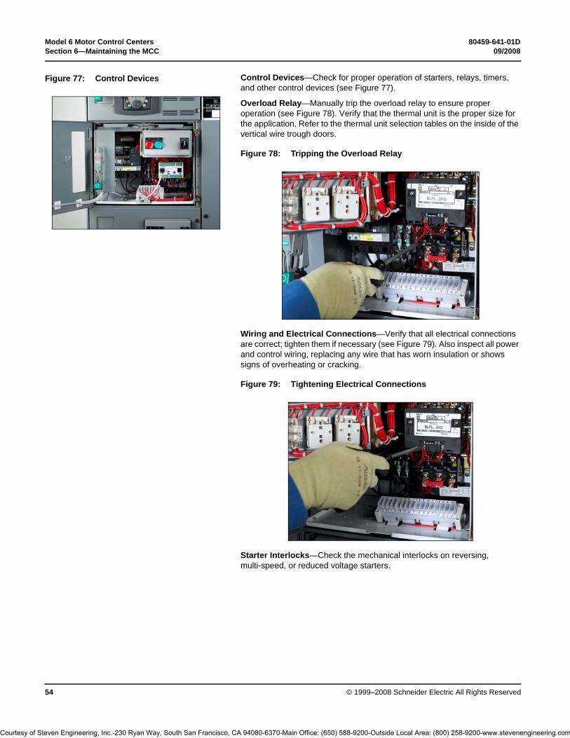
Model 6 Motor Control Centers 80459-641-01DSection 6—Maintaining the MCC 09/2008
© 1999–2008 Schneider Electric All Rights Reserved54
Control Devices—Check for proper operation of starters, relays, timers, and other control devices (see Figure 77).
Overload Relay—Manually trip the overload relay to ensure proper operation (see Figure 78). Verify that the thermal unit is the proper size for the application. Refer to the thermal unit selection tables on the inside of the vertical wire trough doors.
Wiring and Electrical Connections—Verify that all electrical connections are correct; tighten them if necessary (see Figure 79). Also inspect all power and control wiring, replacing any wire that has worn insulation or shows signs of overheating or cracking.
Starter Interlocks—Check the mechanical interlocks on reversing, multi-speed, or reduced voltage starters.
Figure 77: Control Devices
Figure 78: Tripping the Overload Relay
Figure 79: Tightening Electrical Connections
Courtesy of Steven Engineering, Inc.-230 Ryan Way, South San Francisco, CA 94080-6370-Main Office: (650) 588-9200-Outside Local Area: (800) 258-9200-www.stevenengineering.com

80459-641-01D Model 6 Motor Control Centers09/2008 Section 6—Maintaining the MCC
© 1999–2008 Schneider Electric All Rights Reserved 55
Barriers/Insulators—Inspect all insulators, braces, and barriers (see Figure 80); replace any that show signs of arcing damage, tracking, excessive heat, or cracking.
Special Units—Follow the manufacturer’s recommended maintenance procedures for special units (for example: drives, soft starts, and automatic transfer switches).
Reassembly To reassemble the MCC after testing and maintenance, follow the steps below:
1. Reinstall all units by reversing Steps 1–12 in “Removing the Control Unit” beginning on page 48.
2. Confirm the cam mechanism is in the open position; position the mounting slides of the control unit onto the slots of the mid-shelf. Slide the unit inward to engage the cam mechanism.For Compac 6 units, position the mounting slides of the control unit onto the slots of the mid-shelf. Slide the unit inward until the unit is halfway in, then move it inward with a quick push. This movement easily overcomes the compression of the stabs as they engage the vertical bus.
3. Replace all barriers and cover plates and close and fasten all doors.
Figure 80: Manual and Automatic Bus Shutters
Manual Bus Shutter Automatic Bus Shutter
Courtesy of Steven Engineering, Inc.-230 Ryan Way, South San Francisco, CA 94080-6370-Main Office: (650) 588-9200-Outside Local Area: (800) 258-9200-www.stevenengineering.com

Model 6 Motor Control Centers 80459-641-01DSection 6—Maintaining the MCC 09/2008
© 1999–2008 Schneider Electric All Rights Reserved56
Insulation Test
Before an MCC is re-energized (after installation or regular maintenance), take resistance measurements. Use an insulation tester (megohmmeter) with a potential of 500–1000 V.
Take readings between each phase and from each phase to ground, with the branch disconnects off and on. Make sure the main disconnect is off during all insulation tests.
Readings from a megohmmeter with all disconnects off will typically be 5–20 megohms. On new equipment that has been stored in a damp area, lower readings may occur during start-up. If the readings are below one megohm, a few branch units may be energized to help dry out the MCC. If additional readings are above one megohm, additional units may be energized. After the equipment has been in operation for 48 hours, readings should be in the 5–20 megohm range.
When megohmmeter readings are taken with the disconnects on (except for the main), disconnect all devices completing circuits between phases or between phases and neutral (e.g., control transformers). Although readings may be slightly different, observe the one megohm lower limit during start-up.
DANGERHAZARD OF ELECTRIC SHOCK, EXPLOSION, OR ARC FLASH
• Apply appropriate personal protective equipment (PPE) and follow safe electrical work practices. See NFPA 70E.
• This equipment must only be installed and serviced by qualified electrical personnel.
• Turn off all power supplying this equipment before working on or inside equipment.
• Always use a properly rated voltage sensing device to confirm power is off.• Replace all devices, doors, and covers before turning on power to this
equipment.
Failure to follow this instruction will result in death or serious injury.
CAUTIONHAZARD OF EQUIPMENT DAMAGE
• Do not use a megohmmeter on:– adjustable speed drives– solid state soft starters– transient voltage surge suppressor (TVSS) units– AccuSine® active harmonic filter units– PowerLogic® Circuit Monitor units– PowerLogic Power Meter units– capacitor units– any devices not designed to withstand megohmmeter voltage.
• Disconnect all solid state devices such as TVSS’s, drives, soft starts, capacitors, filters, and circuit monitors before performing megohmmeter tests on the MCC.
Failure to follow this instruction can result in equipment damage.
Courtesy of Steven Engineering, Inc.-230 Ryan Way, South San Francisco, CA 94080-6370-Main Office: (650) 588-9200-Outside Local Area: (800) 258-9200-www.stevenengineering.com

80459-641-01D Model 6 Motor Control Centers09/2008 Section 6—Maintaining the MCC
© 1999–2008 Schneider Electric All Rights Reserved 57
Record all megohmmeter readings on the insulation resistance chart on page 93. Any sudden change in resistance values (even within the acceptable range) may indicate potential insulation failure. Early detection and replacement of faulty insulating components helps avoid equipment damage.
If megohmmeter readings are below 5 megohms (one megohm during start-up) consult your Schneider Electric field sales representative.
Re-energize the equipment in sequence, starting with the main devices, the feeder devices next, and then the motor starter devices. (See “Energizing the MCC” beginning on page 45).
Maintenance after a Fault Has Occurred
Excessive currents occurring during a fault may result in structure, component, bus or conductor damage. This damage is caused by mechanical distortion, thermal damage, metal deposits, or smoke from fault currents. After a fault, locate and correct the cause of the fault. Inspect all equipment and make any necessary repairs or replacements before putting the equipment into service again. Make sure all replacement parts are rated properly and are suitable for the application. If in doubt, consult your Schneider Electric field sales representative.
After any fault, perform all maintenance procedures, starting on page 46 and continuing to “Insulation Test” beginning on page 56. Also perform the following procedures after a fault:
1. If the fault occurred downstream from the MCC, perform appropriate maintenance on all equipment involved.
2. Examine the enclosure. External evidence of enclosure damage usually indicates damage within. Extensive damage requires replacement of the enclosure parts and the enclosed equipment.
3. Replace any parts that are damaged or deformed. Pay particular attention to door hinges and door closing hardware. Inspect the area around any damaged units (both inside and out) for displaced parts from the damaged unit. See “Examining the Enclosure” on page 46.
DANGERHAZARD OF ELECTRIC SHOCK, EXPLOSION, OR ARC FLASH
• Apply appropriate personal protective equipment (PPE) and follow safe electrical work practices. See NFPA 70E.
• This equipment must only be installed and serviced by qualified electrical personnel.
• Turn off all power supplying this equipment before working on or inside equipment.
• Always use a properly rated voltage sensing device to confirm power is off.
• Replace all devices, doors, and covers before turning on power to this equipment.
Failure to follow this instruction will result in death or serious injury.
Courtesy of Steven Engineering, Inc.-230 Ryan Way, South San Francisco, CA 94080-6370-Main Office: (650) 588-9200-Outside Local Area: (800) 258-9200-www.stevenengineering.com

Model 6 Motor Control Centers 80459-641-01DSection 6—Maintaining the MCC 09/2008
© 1999–2008 Schneider Electric All Rights Reserved58
4. Examine bus bars and incoming line compartments; tighten all electrical connections to their proper torques. (Table 6 and Figure 81 show typical bus connection points and torque values.) Replace any deformed bus bars or connectors, as well as any showing signs of arcing damage. Inspect all insulators for cracks or burn marks; replace any displaying these characteristics.
5. Follow maintenance procedures for control units. Begin with “Maintaining the Control Unit” beginning on page 47, and continue to “Insulation Test” beginning on page 56. Also perform the steps listed below:
a. Examine the disconnect means for evidence of possible damage. Ensure that the operator mechanism properly turns the disconnect on and off. Exercise the push-to-trip feature on circuit breakers. Make sure that the operator mechanism properly resets the circuit breaker.
b. Check that the door interlock keeps the unit door from opening while the disconnect is in the on position.
NOTE: If the unit door must be opened while the unit is energized, only authorized personnel may operate an interlock defeat mechanism (see Figure 82).
c. Inspect the motor starters for damage. Replace contacts and contact springs if the contacts are welded or show heat damage. If deterioration extends beyond the contacts, replace the entire contactor or starter.
d. Replace the complete overload relay if the thermal units are burned out, or if any indications of arcing or burning are present on the relay.
e. Inspect all fuses and fuse clips. Replace all fuses in a set, even if only one or two are open-circuited.
f. Check all conductors and other devices within the units for signs of damage.
6. Complete an insulation test (see “Insulation Test” beginning on page 56) before placing the MCC back into service.
7. Complete the “Pre-operation Checklist” beginning on page 44.8. Re-energize the equipment. See“Energizing the MCC” beginning on
page 45.
Table 6: Bus Connection Torque Values
Bolted Connection Location Torque Range
Horizontal bus (all locations) 68–70 lb-ft (92.29–94.54 N•m)
Splice bars—0.375 in. diameter bolts 31–32 lb-ft (41.64–43.33 N•m)
Horizontal ground bus (all locations) 5–6 lb-ft (6.75–8.44 N•m)
Figure 81: Typical Bus Connection Points
AØ
AØ
BØ
CØ
AØ
BØ
CØ
BØ CØ
Typical Top-Located 600 A or 800 A Main Lug Compartment
Typical Splice Bar Connection Typical Horizontal Bus Connection
Splice bar
Figure 82: Operating Door Interlock Defeat Mechanism
Courtesy of Steven Engineering, Inc.-230 Ryan Way, South San Francisco, CA 94080-6370-Main Office: (650) 588-9200-Outside Local Area: (800) 258-9200-www.stevenengineering.com

80459-641-01D Model 6 Motor Control Centers09/2008 Section 7—Motor Logic® Solid-State Overload Relay (SSOLR)
© 1999–2008 Schneider Electric All Rights Reserved 59
Section 7—Motor Logic® Solid-State Overload Relay (SSOLR)
The following describes 600 V rated MCC starter units equipped with the Motor Logic solid-state overload relay. Read and understand the safety precautions at the beginning of this bulletin before you install, adjust, or perform maintenance on these units. For full details about MCC installation, refer to “Section 4—Installing the MCC” on page 15.
Figure 83: Motor Logic SSOLR Figure 84: NEMA Rated Compac™ 6 Unit
Figure 85: NEMA Rated Standard Unit
Courtesy of Steven Engineering, Inc.-230 Ryan Way, South San Francisco, CA 94080-6370-Main Office: (650) 588-9200-Outside Local Area: (800) 258-9200-www.stevenengineering.com

Model 6 Motor Control Centers 80459-641-01DSection 7—Motor Logic® Solid-State Overload Relay (SSOLR) 09/2008
© 1999–2008 Schneider Electric All Rights Reserved60
Motor Logic Retrofit Applications
Remove the starter from the unit to replace the overload (melting alloy/bi-metallic). See “Removing the Control Unit” on page 48.
Terminal blocks (OEKTTBML) should be used for applications requiring multiple passes to achieve the proper adjustment range.
Restrain looped load cabling between the overload and the terminal block with wire ties or the equivalent when terminal kits are used.
On Size 3 and 4 starter units, the overload reset button is 1-5/8 in. (41 mm) further from the unit door and may require an alternative reset assembly (80420-862-51).
Retrofitting NEMA rated Compac 6, six-inch (52 mm) units is not recommended. The Motor Logic overload relay is available factory installed in Compac 6.
On 600 V Size 1 applications, add a third wire tie between the circuit breaker and contactor near the contactor line lugs. Refer to instruction bulletin 30072-013-29 for additional information.
NOTE: For retrofit applications, contact your Schneider Electric field sales representative for assistance. Schneider Electric assumes no responsibility for the design or implementation of retrofits unless contracted to perform them.
Use copper wire only on device power and control terminals. Conductors must be sized for 60 °C or 75 °C National Electrical Code® (NEC®) ratings.
Pressure wire terminals are suitable for wire sizes #16–12 AWG, solid or stranded. Terminal instruction labels are located adjacent to the terminal block or on the wireway door.
DANGERHAZARD OF ELECTRIC SHOCK, EXPLOSION, OR ARC FLASH
• Apply appropriate personal protective equipment (PPE) and follow safe electrical work practices. See NFPA 70E.
• This equipment must only be installed and serviced by qualified electrical personnel.
• Turn off all power supplying this equipment before working on or inside equipment.
• Always use a properly rated voltage sensing device to confirm power is off.
• Replace all devices, doors, and covers before turning on power to this equipment.
Failure to follow this instruction will result in death or serious injury.
CAUTIONHAZARD OF EQUIPMENT DAMAGE
• Lug Kits: Use only 9999 LBO and 9999 LLO purchased after 5/1/95 for Size 0, 00B, 00C, and Size 1 units.
• Z Element: Do not use the 9999Z3, 9999Z2, or 9999Z1 developed for open and general enclosed starters.
Failure to follow this instruction can result in equipment damage.
Courtesy of Steven Engineering, Inc.-230 Ryan Way, South San Francisco, CA 94080-6370-Main Office: (650) 588-9200-Outside Local Area: (800) 258-9200-www.stevenengineering.com
80459-641-01D Model 6 Motor Control Centers09/2008 Section 7—Motor Logic® Solid-State Overload Relay (SSOLR)
© 1999–2008 Schneider Electric All Rights Reserved 61
Box lugs (on interposing power terminal blocks supplied with selected units) are suitable for wire sizes #14–8 AWG, solid or stranded. Terminal instruction labels are located adjacent to the terminal block. Table 7 provides additional termination data.
Size 00B, 00C, 0, and 1 relays have conductor (CT) windows through which the motor leads must pass before being connected to the load terminals on the contactor (T1, T2, and T3). By allowing multiple passes (turns) of the load leads through these CT windows, overload protection can be provided for motors with a full-load current lower than the specified operating range. Two passes of the load leads through each window effectively increase (by a multiple of two) the current that the overload relay senses. Three passes effectively increase the current by a multiple of three. All three conductor windows must have the same number of passes, looped in the same direction, for the overload relay to operate properly (see Figure 86).
Passes should begin from the load side of the overload through the CT window and return via the windows provided between the baseplate and overload (see Figure 87). The final pass terminates on the load side of the contactor.
MCC units requiring multiple passes are factory supplied prelooped with #14 AWG wire and interposing terminal blocks. Refer to “Motor Logic Retrofit Applications” on page 60 for information concerning retrofit.
Table 7: Lug Types and Wire Sizes
Class 9065 Motor Logic
Overload Relay Size➀
Rating Lug Type Wire Size➁ Torque Values➃
00B 1.5–4.5 A Pressure Wire➂
14–8 AWG (2.5–6 mm2) 25 lb-in (2.8 N•m)
00C 3–9 A Pressure Wire➂
14–8 AWG (2.5–6 mm2) 25 lb-in (2.8 N•m)
0 6–18 A Box Lug 14–4 AWG (2.5–16 mm2) 50 lb-in (5.6 N•m)
1 9–27 A Box Lug 14–4 AWG (2.5–16 mm2) 50 lb-in (5.6 N•m)
3 30–90 A Box Lug 14–1/0 AWG (2.5–50 mm2) 100 lb-in (11.3 N•m)
4 45–135 A Box Lug 8–250 MCM (6–120 mm2) 200 lb-in (22.6 N•m)
5 90–270 A Box Lug 250–500 MCM (120–240 mm2) 250 lb-in (28.2 N•m)
6 180–540 A Clamp Lug 250–500 MCM (120–240 mm2) 375 lb-in (42.4 N•m)
➀ Refer to the overload relay label next to the adjustment dial.➁ Solid or stranded copper wire, 140 or 167 °F (60 or 75 °C), except 45 to 135 A overload
relay, which is 67 °F (75 °C) wire only.➂ Box lug kit may be supplied, suitable for 14 to 4 AWG wire, 50 lb-in (5.6 N•m) tightening torque.➃ Does not apply to Compac 6 units.
Figure 86: Looping Passes
3 passes shown(load side)
Figure 87: Motor Logic Overload (Bottom View)
CT windows
Return windows(multiple passes)
Courtesy of Steven Engineering, Inc.-230 Ryan Way, South San Francisco, CA 94080-6370-Main Office: (650) 588-9200-Outside Local Area: (800) 258-9200-www.stevenengineering.com

Model 6 Motor Control Centers 80459-641-01DSection 7—Motor Logic® Solid-State Overload Relay (SSOLR) 09/2008
© 1999–2008 Schneider Electric All Rights Reserved62
Adjustment
Turn off all power supplying this equipment before working on or inside the equipment, and follow lockout/tagout procedures. Always use a properly rated voltage sensing device to confirm the power is off.
Overload adjustment information is located on a label inside the unit door (Figure 88) of starter units equipped with the Motor Logic overload relay.
DANGERHAZARD OF ELECTRIC SHOCK, EXPLOSION, OR ARC FLASH
• Apply appropriate personal protective equipment (PPE) and follow safe electrical work practices. See NFPA 70E.
• This equipment must only be installed and serviced by qualified electrical personnel.
• Turn off all power supplying this equipment before working on or inside equipment.
• Always use a properly rated voltage sensing device to confirm power is off.
• Replace all devices, doors, and covers before turning on power to this equipment.
Failure to follow this instruction will result in death or serious injury.
Figure 88: Unit Adjustment Label
DANGERDANGER!
Trip current rating is 1.25 times the overload relay's current adjustment dial setting.Instructions above assume the motor is applied at its rated ambient temperature. For otherconditions, consult the motor manufacturers for current capacity. NOTE: For part winding andmulti-speed applications, use the MFLC of each motor winding as a basis for overloadadjustment. Trip and alarm contact ratings: NEMA A600 and NEMA P300.
SOLID - STATE OVERLOAD RELAYCURRENT RANGE:
SIZE 00C 3 - 9A 1.5 - 4.5A (2 PASSES) 1 - 3A (3 PASSES)
SIZE 0
SIZE 1
SIZE 2
SIZE 3
SIZE 4
6 - 18A
9 - 27A
15 - 45A
30 - 90A
45 - 135A
3 - 9A (2 PASSES)
4.5 -13.5A (2 PASSES)
MULTIPLE PASSES NOT AVAILABLE
MULTIPLE PASSES NOT AVAILABLE
MULTIPLE PASSES NOT AVAILABLE
2 - 6A (3 PASSES)
3 - 9A (3 PASSES)
* Passes refer to multiple looping through overload windows.
Failure to follow these instructions will result in death,serious injury or equipment damage.
Turn off power supplying equipmentbefore working inside.
For fusible switch starter units, power fusesmust be selected in accordance with Article430 of the NEC. Class RK5 fuses arerecommended for NEMA rated applications.
HAZARD OF ELECTRIC SHOCK, BURN OREXPLOSION
80438-651-01 G
•
REV
OPERATING INSTRUCTIONS; For continuous-rated motors with service factors of 1.0, multiply the motor
full-load current (MFLC) by the number of passes through the overload relay'swindows (1,2 or 3) and set the overload relay's current adjustment dial to 90% of thisvalue. For continuous-rated motors with service factors of 1.15 to 1.25, multiply theMFLC by the number of passes through the overload relay's windows (1,2 or 3) andset the overload current adjustment dial to this value.
Use only Class J fuses for Compac™ 6 units.
•
•
SIZE 00B 1.5 - 4.5A 0.75 - 2.25A (2 PASSES) 0.5 - 1.5A (3 PASSES)
Courtesy of Steven Engineering, Inc.-230 Ryan Way, South San Francisco, CA 94080-6370-Main Office: (650) 588-9200-Outside Local Area: (800) 258-9200-www.stevenengineering.com
80459-641-01D Model 6 Motor Control Centers09/2008 Section 8—Mag-Gard® and PowerPact® Motor Circuit Protector Settings
© 1999–2008 Schneider Electric All Rights Reserved 63
Section 8—Mag-Gard® and PowerPact® Motor Circuit Protector Settings
The National Electrical Code® (NEC®) and Canadian Electrical Code (CEC) require that magnetic starters, used in combination with adjustable magnetic trip-only circuit breakers, have an overload relay in each conductor. Mag-Gard or PowerPact Motor Circuit Protectors are the standard motor circuit protectors used in Model 6 MCCs.
Adjusting Mag-Gard or PowerPact Magnetic Trip Setting
The adjustable magnetic trip setting is factory-set at Lo for Mag-Gard Motor Circuit Protectors. For PowerPact H- and J-frame Motor Circuit Protectors, the Full Load Amp Setting (FLA) is factory set to the lowest position and the instantaneous trip setting (Im) is factory set to the Auto 1 position. For PowerPact P-frame Motor Circuit Protectors (ET1.0M electronic trip unit), the adjustable instantaneous trip setting is factory set to its lowest position. These settings may have to be adjusted for proper motor start-up. For both Mag-Gard and PowerPact Motor Circuit Protectors, refer to the magnetic trip setpoint limits outlined in the applicable national installation codes. For PowerPact H- and J-frame Motor Circuit Protectors, refer also to the PowerPact Motor Circuit Protector Settings instruction bulletin (48940-260-01) shipped with the equipment.
To access the Mag-Gard trip adjustment dial:
1. Turn off all power supplying this equipment before working on or inside the equipment, and follow lockout/tagout procedures. Always use a properly rated voltage sensing device to confirm the power is off.
2. Place the unit handle in the “Off” position and open the door.3. While pushing the door interlock lever forward, trip the circuit breaker by
pressing the yellow test button (see Figure 89). The disconnect handle will automatically move up, allowing access to the adjustment dial.
After obtaining the motor full load current from the motor nameplate, select an adjustable trip setpoint to test start the motor. Further adjustments may be required because of motor load characteristics. Refer to applicable national installation codes for permissible setpoints.
After adjusting the trip setting, reset the circuit breaker by moving the disconnect handle to the “On” position and then to the “Off” position.
DANGERHAZARD OF ELECTRIC SHOCK, EXPLOSION, OR ARC FLASH
• Apply appropriate personal protective equipment (PPE) and follow safe electrical work practices. See NFPA 70E.
• This equipment must only be installed and serviced by qualified electrical personnel.
• Turn off all power supplying this equipment before working on or inside equipment.
• Always use a properly rated voltage sensing device to confirm power is off.• Replace all devices, doors, and covers before turning on power to this
equipment.
Failure to follow this instruction will result in death or serious injury.
Figure 89: Mag-Gard Magnetic Trip Adjustment
Trip adjustment dial
Test button
Courtesy of Steven Engineering, Inc.-230 Ryan Way, South San Francisco, CA 94080-6370-Main Office: (650) 588-9200-Outside Local Area: (800) 258-9200-www.stevenengineering.com

Model 6 Motor Control Centers 80459-641-01DSection 8—Mag-Gard® and PowerPact® Motor Circuit Protector Settings 09/2008
© 1999–2008 Schneider Electric All Rights Reserved64
To access the PowerPact H- and J-frame Full Load Amps (FLA) and Instantaneous Trip setting (Im) dials:
1. Turn off all power supplying this equipment before working on or inside the equipment, and follow lockout/tagout procedures. Always use a properly rated voltage sensing device to confirm the power is off.
2. Place the unit handle in the “Off” position and open the door.3. To set the FLA and Im dials, refer to the PowerPact Motor Circuit
Protector Settings instruction bulletin (48940-260-01) shipped with the equipment.
NOTES: • Select replacement Mag-Gard or PowerPact Motor Circuit Protectors for MCCs using the voltage and current ratings listed in the Model 6 MCC Catalog (8998CT9701) in addition to the Mag-Gard or PowerPact selection tables in the Square D Digest.
• These circuit breakers are suitable for motors with locked-rotor indicating code letters based on applicable national codes and standards. For other motors, consult your local Schneider Electric field sales representative.
To access the PowerPact P-frame Instantaneous Trip setting (Im) dial:
1. Turn off all power supplying this equipment before working on or inside the equipment, and follow lockout/tagout procedures. Always use a properly rated voltage sensing device to confirm the power is off.
2. Place the unit handle in the “Off” position and open the door.3. Make adjustments as follows:
a. For ET1.0I and ET1.0M electronic trip units, adjust instantaneous trip (Ii) by adjusting switch A (see Figure 91). Switch settings are multiples of the frame rating.
b. For Micrologic electronic trip units, see the instruction bulletin shipped with the circuit breaker.
After obtaining the motor full load current from the motor nameplate, select an adjustable trip setpoint to test start the motor. Further adjustments may be required because of motor load characteristics. Refer to applicable national installation codes for permissible setpoints.
Figure 90: PowerPact H- and J-frame Magnetic Trip Adjustment
Instantaneoustrip setting dial
Full loadamps dial
Figure 91: PowerPact P-frame Instantaneous Trip Adjustment
A
Courtesy of Steven Engineering, Inc.-230 Ryan Way, South San Francisco, CA 94080-6370-Main Office: (650) 588-9200-Outside Local Area: (800) 258-9200-www.stevenengineering.com

80459-641-01D Model 6 Motor Control Centers09/2008 Section 9—iMCC
© 1999–2008 Schneider Electric All Rights Reserved 65
Section 9—iMCC This section includes instructions for the Model 6 Intelligent MCC (iMCC).
iMCC Overview Model 6 iMCCs feature the same overall structure and unit features as Model 6 Motor Control Centers with additional “intelligent” capabilities. Two popular methods for configuring Model 6 iMCCs to customize your application are:
• iMCC-Hardwired I/O: PLC Interwiring• iMCC-Network: Network Cabling
iMCC-Hardwired I/O: PLC Interwiring
This method offers a hardwired I/O system in the Model 6 MCC that provides basic information and control capabilities. With the I/O mounted in the MCC, the starters are wired to the I/O at the Schneider Electric manufacturing plant, and the system is tested prior to shipment.
iMCC-Network: Network Cabling
A key feature of our iMCC-Network solution is the integration of intelligent devices and device level networks for control and automation that delivers improved performance. Popular network protocols such as CANopen, DeviceNet™, Ethernet, Modbus®, and PROFIBUS communicate directly to every unit of the iMCC for an effective method of connecting centralized control to widely distributed I/O.
Networking allows for easy monitoring of critical data of each motor or load connected to the iMCC, enabling precise process control at all times. With this information, your staff can respond to potential problems proactively. Real-time access to information and records of last faults allows for simplified diagnostics and reduced downtime.
The network cabling consists of a solution that is appropriate for your selected communication network. Our industry-leading, full-depth wireway effectively separates network cabling from high voltage cabling. Additionally, our standard wireway barrier isolates the communication cabling from the load cabling routed in the vertical wireway.
Networks/Communications Overview
iMCCs contain Schneider Electric devices with communication ports. Each device has a unique internal register map. These devices may be linked together to a single point.
The Schneider Electric publications listed in Table 1 on page 9 may be useful in the setup, maintenance, and regular operation of your Model 6 iMCC. Upon request, your Schneider Electric field sales representative can provide them to you in print. Or, you can download these documents from the Technical Library at www.schneider-electric.us.
Courtesy of Steven Engineering, Inc.-230 Ryan Way, South San Francisco, CA 94080-6370-Main Office: (650) 588-9200-Outside Local Area: (800) 258-9200-www.stevenengineering.com

Model 6 Motor Control Centers 80459-641-01DSection 9—iMCC 09/2008
© 1999–2008 Schneider Electric All Rights Reserved66
Connecting the iMCC Cabling System
Units within iMCCs are connected at the factory. The cable used varies with the network type. The pin outs for the various networks are shown in Table 8:
Network Cabling Factory supplied network cabling is installed in accordance with UL 845 procedures and practices, and routed in the bottom horizontal wireway.
In order to make direct connections to Class 2 or Class CM systems, install Class 2 or Class CM wiring so that it is separated from power conductors either by a barrier or a minimum space of 0.25 in. (6 mm). Route power conductors in the top horizontal wireway for maximum separation.
External network cabling must comply with Class 2 or Class CM practices under the provisions of NEC Articles 725 and 800.
Cables Between Shipping Splits Connect the trunk line cables between shipping splits by aligning the keyways and plugging the male end of the trunk cable to the female end of the next trunk cable. Screw the coupling ring until it is hand-tight. Repeat this process until all shipping splits are connected.
Load Cables It is recommended to route all load cables in the top horizontal wireway to keep them isolated from the communications cabling. If you route the load cables in the bottom horizontal wireway, make sure to maintain a 0.25-in. (6 mm) distance between the communications cabling and all other cabling.
Communication Networks There are three primary ways to connect communication networks: via bridges/repeaters, programmable logic controllers (PLCs), or a direct cable connection. Follow the applicable instructions below to make the cabling connections for your Model 6 iMCC.
Bridges/Repeaters If the PLC is not in the local area of the MCC, you will typically need to use a bridge/repeater to connect the communication network.
Terminating Resistors In order for the communication network to operate properly, terminating resistors are required on each end of the network. If your iMCC is shipped with a bridge, repeater, and/or PLC, external terminal blocks (MCT485) are included with shipment.
Direct Cable Connection
Follow the steps below to connect a cable directly to the network via the iMCC network cable.
1. Determine which end (male or female) of the iMCC network you will attach to your cable.
2. Strip back the communication cabling insulation.3. Based on the network, use the pin outs given in the table at left.
CAUTIONHAZARD OF EQUIPMENT DAMAGEDo not use excessive force when making iMCC cabling connections. Connections are keyed to ensure that pins are properly aligned.
Failure to follow this instruction can result in equipment damage.
Table 8: Pin Outs for iMCC Networks
Network Cable ColorBlue White Red Black Bare
Modbus (2-wire RS-485) Signal + Signal - Not usedShieldPROFIBUS A (Neg) B (Pos)
DeviceNet CAN_L CAN_H V + V -CANopen
Table 9: Network Connection Pin Outs
Field Connection Termination
5-Pin Female/MaleModbus and PROFIBUS
DeviceNet and CANopen
Pin # 1 Shield ShieldPin # 2 Unused RedPin # 3 Unused BlackPin # 4 White WhitePin # 5 Blue Blue
Courtesy of Steven Engineering, Inc.-230 Ryan Way, South San Francisco, CA 94080-6370-Main Office: (650) 588-9200-Outside Local Area: (800) 258-9200-www.stevenengineering.com

80459-641-01D Model 6 Motor Control Centers09/2008 Section 9—iMCC
© 1999–2008 Schneider Electric All Rights Reserved 67
Figure 92: Typical Cabling Scheme for Modbus® Two-Wire
Section 1 Section 2
Single tap trunk cable (5000129-295)
ATV61/71 9-pin connector cable (5000129-501)
6-tap trunk cable assembly (5000129-83)
Female terminator (5000129-187)
Device cable—general cables (5000129-75)
20 in. (508 mm) extension (optional) (5000129-76)
Male terminator (5000129-186)
ATS48 cable (5000129-75)
NOTE: Shield must be grounded at one end only.
Orderable Item
PartNumber
Cap for unused male end or tap 3463512-1
Cap for unused female end or tap 3463512-3
Mini female field attachable connector
5000129-287
Mini male field attachable connector
5000129-292
20 in. (508 mm) trunk extension 5000129-76
25 in. (635 mm) trunk extension 5000129-78
30 in. (762 mm) trunk extension 5000129-79
35 in. (889 mm) trunk extension 5000129-80
25 ft. (10.7 m) cable extension 5000129-81
Courtesy of Steven Engineering, Inc.-230 Ryan Way, South San Francisco, CA 94080-6370-Main Office: (650) 588-9200-Outside Local Area: (800) 258-9200-www.stevenengineering.com

Model 6 Motor Control Centers 80459-641-01DSection 9—iMCC 09/2008
© 1999–2008 Schneider Electric All Rights Reserved68
Figure 93: Typical Cabling Scheme for DeviceNet™ and CANopen (8A cable)
Section 1 Section 2
Single tap trunk cable (80420-921-01)
6-tap trunk cable assembly (80420-915-50)
Female terminator (DN150)
Device cable (80420-916-01)
20 in. (508 mm) trunk cable (80420-918-01)
Male terminator (DN100)
Male cap (D970CAPR)
Mini-mini tee (DN3020)
NOTE: Shield must be grounded at one end only.
Orderable Item
PartNumber
Mini female field attachable connector
1A5000-34DN
Mini male field attachable connector
1A5006-34DN
25 in. (635 mm) trunk cable 80420-919-01
30 in. (762 mm) trunk cable 80420-920-01
35 in. (889 mm) trunk cable 80420-921-01
Courtesy of Steven Engineering, Inc.-230 Ryan Way, South San Francisco, CA 94080-6370-Main Office: (650) 588-9200-Outside Local Area: (800) 258-9200-www.stevenengineering.com

80459-641-01D Model 6 Motor Control Centers09/2008 Section 9—iMCC
© 1999–2008 Schneider Electric All Rights Reserved 69
Figure 94: Typical Cabling Scheme for PROFIBUS
Section 1 Section 2
Single tap trunk cable (5000129-295)
ATV61/71 9-pin connector cable (5000129-140)
6-tap trunk cable assembly (5000129-83)
Device cable (5000129-75)
20 in. (508 mm) extension (optional) 5000129-76
ATS48 cable (5000129-75)
Grounding tee (5000129-230)
NOTE: Shield must be grounded in all sections.
Orderable Item
PartNumber
Cap for unused male end or tap 3463512-1
Cap for unused female end or tap 3463512-3
20 in. (508 mm) trunk extension 5000129-76
25 in. (635 mm) trunk extension 5000129-78
30 in. (762 mm) trunk extension 5000129-79
35 in. (889 mm) trunk extension 5000129-80
25 ft. (10.7 m) cable extension 5000129-81
NOTE: The network is terminated in a Termination Unit.
Courtesy of Steven Engineering, Inc.-230 Ryan Way, South San Francisco, CA 94080-6370-Main Office: (650) 588-9200-Outside Local Area: (800) 258-9200-www.stevenengineering.com

Model 6 Motor Control Centers 80459-641-01DSection 9—iMCC 09/2008
© 1999–2008 Schneider Electric All Rights Reserved70
Operation This section contains pre-operation checklists, energizing procedures, and remote and local programming procedures for TeSys® T and Motor Logic Plus™ motor protection relays, PowerLogic® Power Meter, PowerLogic Circuit Monitor, Altivar® drives, and Altistart® soft starts.
Pre-operation Checklists To verify that the iMCC is operating properly, complete both of the following checklists before energizing the equipment:
MCC Structure ❏ Complete the maintenance procedures beginning on page 46 and continuing up to “Insulation Test” on page 56. This initial maintenance is necessary to detect any shipping damage or loose connections. Do not energize the MCC until initial maintenance is complete. NOTE: The following maintenance procedures are not necessary before energizing the MCC for the first time: Control Unit Removal, Stab Assemblies, Starter Contacts and Barriers/Insulators.
❏ Perform an insulation test on the MCC (see “Insulation Test” on page 56).
❏ If the MCC is equipped with ground fault protection, properly adjust and test the ground fault protective device before energizing.
❏ Remove all blocks or other temporary holding means from the electrical devices.
❏ Remove any secondary shunt bars from the current transformers. Do not operate a current transformer with its secondary shunt bars open-circuited.
❏ Manually exercise all switches, circuit breakers, and other operator mechanisms to ensure that they are properly aligned and operate freely.
❏ Electrically exercise all electrically-operated switches, circuit breakers, and other mechanisms (but not under load) to ensure that the devices operate properly. This may require an auxiliary source of control power.
❏ Verify proper interval and contact operation of the timers.❏ Set the Motor Logic Plus overcurrent setting to the maximum service
factor amperage of the motor to ensure that the proper overload protection is provided. The Motor Logic Plus overcurrent threshold is set at the lowest setting at the factory. Verify that all other settings are optimized for the application.
❏ The Parameter Settings Sheet lists all the parameters that have been changed from the original, default settings. Any settings not shown on this sheet will retain their original, default values.
❏ Verify that all load and remote control connections have been made and that they agree with the wiring diagrams provided.
❏ Verify that all ground connections are made properly.❏ Install the covers and close the doors; verify that they are all properly
tightened.
Courtesy of Steven Engineering, Inc.-230 Ryan Way, South San Francisco, CA 94080-6370-Main Office: (650) 588-9200-Outside Local Area: (800) 258-9200-www.stevenengineering.com

80459-641-01D Model 6 Motor Control Centers09/2008 Section 9—iMCC
© 1999–2008 Schneider Electric All Rights Reserved 71
iMCC CommunicationsBefore energizing the equipment, check the items below to verify that the iMCC networking and cabling are set up and connected properly.
Cabling Connections
• Verify that the network length without a repeater is less than 1500 feet (457 m).
• Verify that the MCC cables are connected between shipping splits. See “Cables Between Shipping Splits” on page 66 for instructions.
• Verify that each device tap cable is properly connected to the main trunk line.
• Verify that all network connections are secure.• Verify that terminating resistors are installed as required per network
protocol.
Communications Setup
• Verify that all devices have been assigned correct addresses; see “Device Addressing” on page 81 for specific addressing parameters.
Energizing the MCC
To energize the MCC:
1. Review the “Pre-operation Checklists” on page 70 before energizing. 2. Turn off all downstream loads, including distribution equipment and
other devices that are remote from the MCC. 3. Verify that all barriers, doors, and covers are closed before energizing
the equipment.4. Energize the equipment in sequence, starting with the main devices, the
feeder devices next, and then the motor starter devices. 5. With all barriers in place and all unit doors closed and latched, turn on
the devices with a firm, positive motion. 6. After all disconnect devices are closed, you may energize loads such as
lighting circuits, starters, contactors, heaters, and motors.
CAUTIONHAZARD OF EQUIPMENT DAMAGE
Do not use excessive force when making cabling connections. Connections are keyed to ensure that pins are properly aligned.
Failure to follow this instruction can result in equipment damage.
DANGERHAZARD OF ELECTRIC SHOCK, EXPLOSION, OR ARC FLASH
• Apply appropriate personal protective equipment (PPE) and follow safe electrical work practices. See NFPA 70E.
• This equipment must only be installed and serviced by qualified electrical personnel.
• Turn off all power supplying this equipment before working on or inside equipment.
• Always use a properly rated voltage sensing device to confirm power is off.
• Replace all devices, doors, and covers before turning on power to this equipment.
• Review the “Pre-operation Checklists” beginning on page 70, and verify that all items check out.
Failure to follow this instruction will result in death or serious injury.
Courtesy of Steven Engineering, Inc.-230 Ryan Way, South San Francisco, CA 94080-6370-Main Office: (650) 588-9200-Outside Local Area: (800) 258-9200-www.stevenengineering.com

Model 6 Motor Control Centers 80459-641-01DSection 9—iMCC 09/2008
© 1999–2008 Schneider Electric All Rights Reserved72
Motor Logic Plus Local Programming
Local programming can be used for Motor Logic Plus setpoint programming and error readout purposes. Verify that the display is unlocked (the default setting), and disconnect all power before performing the steps below to accomplish local programming:
1. Turn off all power supplying this equipment before working on or inside the equipment, and follow lockout/tagout procedures. Always use a properly rated voltage sensing device to confirm the power is off.
2. Connect a 9 V supply to the “P” and “G” terminals using the supplied connector, part # 80445-519-50 (see Figure 95).
3. Turn the “Mode Select” switch to the parameter you are programming. Refer to bulletin # 30072-013-98_ (see “iMCC Related Literature” on page 10) for a list of parameters.
4. Press and hold the “Reset/Program” button.NOTE: The display will not illuminate for local programming if the “Mode Select” switch is in the “Run” position.
DANGERHAZARD OF ELECTRIC SHOCK, EXPLOSION, OR ARC FLASH
• Apply appropriate personal protective equipment (PPE) and follow safe electrical work practices. See NFPA 70E.
• Turn off all power supplying this equipment before working on or inside the Motor Control Center.
• Use a properly rated voltage sensing device to confirm that all power is off. Control units must be de-energized before performing maintenance on the MCC.
• The unit disconnect switch must be locked in the “off” position before working on equipment.
Failure to follow this instruction will result in death or serious injury.
Figure 95: Motor Logic Plus Communication Module Terminals
Black (–)
Red (+)
Battery connector 9V
NOTE: The jumpers are for 2-wire operation. They must be removed for 4-wire networks.
A Receive pair (–) polarity
B Receive pair (+) polarity
Y Transmit pair (–) polarity
Z Transmit pair (+) polarity
S Shield
R Remote reset switch
R Remote reset switch
G Ground (–) *
P Power (+) *
* For programming
Courtesy of Steven Engineering, Inc.-230 Ryan Way, South San Francisco, CA 94080-6370-Main Office: (650) 588-9200-Outside Local Area: (800) 258-9200-www.stevenengineering.com

80459-641-01D Model 6 Motor Control Centers09/2008 Section 9—iMCC
© 1999–2008 Schneider Electric All Rights Reserved 73
5. Turn the “Display/Program” dial to the desired setting as shown on the LED display.
6. Release the “Reset/Program” button.7. Turn the “Mode Select” switch back to the “Run” position.8. Disconnect the 9 V supply and its connector.
Error messages are displayed on the 3-digit LED display when harmful conditions are detected. Table 10 contains a list of the error message codes and their definitions.
Motor Logic Plus Remote Programming Remote programming can be used for setpoint programming and data acquisition purposes. Follow the steps below to remotely configure the Motor Logic Plus overload. (See Table 11 for a description of the command line codes referenced in the steps.)
1. Stop the overload by sending code “02H” to the command register (C6H).2. If network programming has not been enabled, send code “05H” to the
command register.3. Program the appropriate parameter. See Table 12 on page 74 for a
register map with a list of parameters. For more detailed information, refer to bulletin # 30072-013-102_. See Table 13 on page 75 and Table 14 on page 76 to determine the location and addressing of parameters within the Motor Logic Plus register map.
4. Restart the overload by using code “01H.”
Table 10: Local Error Display
Displayed Message Meaning
oc Tripped on over current
SP Tripped on single phasing
ub Tripped on voltage or current unbalance
uC Tripped on under current
cF Tripped on contactor failure
GrF Tripped on ground fault
HI Tripped on high voltage
Lo Tripped on low voltage
rP Incoming phases have been reversed
oFF A stop command was issued from a remote source
Table 11: Command Line Codes
Code Command
01H Start/reset
02H Stop
03H Display lock
04H Display unlock
05H Network program enable
06H Network program disable
07H Network watchdog enable
08H Network watchdog disable
The network watchdog feature disables the Motor Logic Plus SSOLR when the device does not receive a valid communication within a 10 s period.
Courtesy of Steven Engineering, Inc.-230 Ryan Way, South San Francisco, CA 94080-6370-Main Office: (650) 588-9200-Outside Local Area: (800) 258-9200-www.stevenengineering.com

Model 6 Motor Control Centers 80459-641-01DSection 9—iMCC 09/2008
© 1999–2008 Schneider Electric All Rights Reserved74
Table 12: Motor Logic Plus Address Descriptions
OperationAddress
Code Description NotesRAM Relative
Read only (all registers are 16-bit words)
A0 1A0 VOLTAV Average voltage L–L V~
A2 1A1 IAVE Raw average current A (x100, x10, x1), multiplied by scale factor
A4 1A2 VUB Voltage unbalance 0–100%
A6 1A3 IUB Current unbalance 0–100%
A8 1A4 PFANGLE Power factor angle Degrees
AA 1A5 CAPTY Thermal capacity remaining 0–100%
AC 1A6 GFC Ground fault current A (x100, x10, x1), multiplied by scale factor
AE 1A7 ERCODE/TRIPRN Real time error (RTE) and trip indicator (TI) 8-bit nibble-coded RTE; 8-bit coded TI
B0 1A8 FH Fault history Fault order: 4th, 3rd, 2nd, Last
B2 1A9 PID Manufacture year/model and scale 8-bit year; 8-bit ID and scale
B4 1AA VA-C Line voltage A–C V~
B6 1AB VB-C Line voltage B–C V~
B8 1AC VA-B Line voltage A–B V~
BA 1AD IC Raw current phase C A (x100, x10, x1), multiplied by scale factor
BC 1AE IB Raw current phase B A (x100, x10, x1), multiplied by scale factor
BE 1AF IA Raw current phase A A (x100, x10, x1), multiplied by scale factor
C0 1Bo RD1 Remaining restart delay RD1
C2 1B1 RD2 Remaining restart delay RD2
C4 1B2 RD3 Remaining restart delay RD3
C6 1B3 COMLINE Command line code (address C6H) see Table 11 (write only)
C8 1B4 Scale PowerLogic scale parameter (read only) 0, 1, 2; 16-bit signed word (2’s complement, read only)
CA 1B5 LV Low voltage threshold 170 V~ to HV (600 V~ model; 450 V~ to HV)
CC 1B6 HV High voltage threshold LV to 528 V~ (600 V~ model; LV to 660 V~)
Read only (all registers are 16-bit words)
CE 1B7 VUB Voltage unbalance threshold 2–15%, or 999 (off)
D0 1B8 MULT Effective turns ratio Determined by model
D2 1B9 OC Overcurrent threshold Current range of SSOLR
D4 1BA UC Undercurrent threshold 0.5 x OC Min. to OC Max., Off
D6 1BB CUB Current unbalance threshold 2–25%, or 999 (off)
D8 1BC TC Overcurrent trip class 5, J5, 10, J10, 15, J15, 20, J20, 30, J30 (J = Jam protection is enabled)
DA 1BD RD1 Rapid cycle timer 2–500 s
DC 1BE RD2 Restart delay RD2 2–500 min.
DE 1BF RD3 Restart delay RD3 2–500 min.
E0 1C0 #RU Restarts after UC 0, 1, 2, 3, 4, A
E2 1C1 #RF Number of restarts0, 1, oc1, 2, oc2, 3, oc3, 4, oc4, A, ocA(0 = manual, A = continuous, oc = automatic restart after RD2 expires)
E4 1C2 UCTD Undercurrent trip delay 2–60 s
E6 1C3 GF Ground fault threshold 0.15 x OC Min. to 0.2 x OC Max., Off
E8 1C4 ADDR RS-485 slave address 01–99
Required for PowerLogic software.
Courtesy of Steven Engineering, Inc.-230 Ryan Way, South San Francisco, CA 94080-6370-Main Office: (650) 588-9200-Outside Local Area: (800) 258-9200-www.stevenengineering.com

80459-641-01D Model 6 Motor Control Centers09/2008 Section 9—iMCC
© 1999–2008 Schneider Electric All Rights Reserved 75
Table 13: Read-Only Registers
RAM Address
Relative Address Code Description Notes
A0 1A0 VOLTAV Average voltage L-L Volts
A2 1A1 IAVE Raw average current A (x100, x10, x1), multiplied by scale factor
A4 1A2 VUB Voltage unbalance 0–100%
A6 1A3 IUB Current unbalance 0–100%
A8 1A4 PFANGLE Power factor angle Degrees
AA 1A5 CAPTY Thermal capacity remaining 0–100%
AC 1A6 GFC Ground fault current A (x100, x10, x1), multiplied by scale factor
AE 1A7 ERCODE/TRIPRN Bit-real time errors and trip indicator
Bit # TRIPRN ERCODE0 Fault lockout Low voltage
1 Remote stop High voltage
2 Contactor failure Unbalance voltage
3 Under current Under current
4 Over current Phase reversal
5 Ground fault Unbalance current
6 Current unbalance Single phase voltage > 25%
7 Current single phase > 50% unbalance Single phase current > 50%
B0 1A8 FH NIBBLE_CODED -4 fault history
The four-fault history is based on the following scheme: 16 15 14 13 12 11 10 9 8 7 6 5 4 3 2 1, where bits 1–4 = Last fault, bits 5–8 = 2nd last fault, bits 9–12 = 3rd last fault, and bits 13–16 = 4th last fault. These four bits indicate a hex value that corresponds to the following faults:
01 High voltage
02 Low voltage
03 N/A
04 Contactor failure
05 Phase reversal
06 Single phase
07 Ground fault
08 Current unbalance
09 Remote off command
10 Overcurrent
11 Undercurrent
B2 1A9 PID Manufacture year, month, product type/scale 8-bit year, 4-bit month, 4-bit I/O and scale
B4 1AA VA-C Line voltage A–C Volts
B6 1AB VB-C Line voltage B–C Volts
B8 1AC VA-B Line voltage A–B Volts
BA 1AD IC Raw current phase C A (x100, x10, x1), multiplied by scale factor
BC 1AE IB Raw current phase B A (x100, x10, x1), multiplied by scale factor
BE 1AF IA Raw current phase A A (x100, x10, x1), multiplied by scale factor
C0 1B0 RD1 Remaining restart delay RD1 Seconds
C2 1B1 RD2 Remaining restart delay RD2 Seconds
C4 1B2 RD3 Remaining restart delay RD3 Seconds
Must be used with PowerLogic software Can only be viewed via network
Courtesy of Steven Engineering, Inc.-230 Ryan Way, South San Francisco, CA 94080-6370-Main Office: (650) 588-9200-Outside Local Area: (800) 258-9200-www.stevenengineering.com
Model 6 Motor Control Centers 80459-641-01DSection 9—iMCC 09/2008
© 1999–2008 Schneider Electric All Rights Reserved76
Table 14: Read/Write Registers
RAM Address
Relative Address Code Description Range Default
C6 1B3 COM-LINE Command Line Reset/run/stop, display lock, network configuration enable
Motor Logic Plus Command Register (C6 hex)01H Start/reset
02H Stop
03H Display lock
04H Display unlock
05H Network program enable
06H Network program disable
C8 1B4 Scale PowerLogic scale parameter 0, 1, 1–2; 16-bit signed word (2s complement, read only) Model dependent
CA 1B5 LV Low voltage threshold 170 V (450 V )- HV setting 435
CC 1B6 HV High voltage threshold LV setting - 528 V (660 V ) 500
CE 1B7 VUB Voltage unbalance threshold 2–15% or 999% 5%
D0 1B8 MULT CT/turns effective ratio 1 or 10–200 1
D2 1B9 OC Overcurrent threshold OL current range Min. rating
D4 1BA UC Undercurrent threshold 0.5 x OC Min. to OC Max., Off 0.8 x OC Min.
D6 1BB CUB Current unbalance threshold 2–25% or 999% 6%
D8 1BC TC Overcurrent trip class5, J5, 10, J10, 15, J15, 20, J20, 30, J30 (J = Jam protection is enabled)
5 5 decimal
J5 133 decimal
10 10 decimal
J10 138 decimal
15 15 decimal
J15 143 decimal
20 20 decimal
J20 148 decimal
30 30 decimal
J30 158 decimal
DA 1BD RD1 Rapid cycle timer 2–500 seconds 10
DC 1BE RD2 Restart delay all faults except undercurrent 2–500 minutes 8
DE 1BF RD3 Restart delay after undercurrent 2–500 minutes 20
E0 1C0 #RU # Restarts after undercurrent 0, 1, 2, 3, 4, A (Automatic)
RU Values8.1 0–4 in decimal
8.2 A = 255 decimal
E2 1C1 #RF # Restarts all faults except undercurrent
0, 1, oc1, 2, oc2, 3, oc3, 4, oc4, A, ocA(0 = manual, A = continuous, oc = automatic restart after RD2 expires)
RF Values0 1 decimal
1 2 decimal
oc1 3 decimal
2 4 decimal
oc2 5 decimal
3 6 decimal
oc3 7 decimal
4 8 decimal
oc4 9 decimal
A 10 decimal
ocA 11 decimal
E4 1C2 UCTD Undercurrent trip delay 2–60 seconds 5
E6 1C3 GF Ground fault current threshold (0.4) AOL current range or Off 0.15 x Min.
E8 1C4 ADDR RS-485 slave address 01–99 1
Can only be viewed via network
Courtesy of Steven Engineering, Inc.-230 Ryan Way, South San Francisco, CA 94080-6370-Main Office: (650) 588-9200-Outside Local Area: (800) 258-9200-www.stevenengineering.com

80459-641-01D Model 6 Motor Control Centers09/2008 Section 9—iMCC
© 1999–2008 Schneider Electric All Rights Reserved 77
TeSys® T Motor Management Controller
The following describes MCC starter units equipped with the TeSys T Motor Management Controller. Read and understand the safety precautions at the beginning of this bulletin before you install, adjust, or perform maintenance on these units. For full details about MCC installation, refer to “Section 4—Installing the MCC” on page 15.
Figure 96: TeSys T Controllers
Modbus®
DeviceNet™
PROFIBUS
Ethernet
CANopen
Figure 97: NEMA Rated Control Unit (TeSys T Modbus)
Courtesy of Steven Engineering, Inc.-230 Ryan Way, South San Francisco, CA 94080-6370-Main Office: (650) 588-9200-Outside Local Area: (800) 258-9200-www.stevenengineering.com

Model 6 Motor Control Centers 80459-641-01DSection 9—iMCC 09/2008
© 1999–2008 Schneider Electric All Rights Reserved78
TeSys T Retrofit Applications
Remove the starter from the unit to replace the overload (melting alloy/bi-metallic). See “Removing the Control Unit” on page 48.
Terminal blocks (OEKTTBML) should be used for two-speed applications requiring multiple passes to achieve the proper adjustment range.
Restrain looped load cabling between the TeSys T controller and the terminal block with wire ties (or the equivalent) when terminal kits are used.
On 600 V Size 1 applications, add a third wire tie between the circuit breaker and contactor near the contactor line lugs. Refer to instruction bulletin 30072-013-29 for additional information.
NOTE: For retrofit applications, contact your Schneider Electric field sales representative for assistance. Schneider Electric assumes no responsibility for the design or implementation of retrofits unless contracted to perform them.
Use copper wire only on device power and control terminals. Conductors must be sized for 60 °C or 75 °C National Electrical Code® (NEC®) ratings.
Pressure wire terminals are suitable for single conductor wire sizes #24–14, solid or stranded. Two conductor wire size is #24–18. Terminal instruction labels are located adjacent to the terminal block or on the wireway door.
Applications Requiring Turns There are some applications that require more than one wiring turn through the TeSys T controller.
• All NEMA Size 4 applications require three passes through separately mounted current transformers (CTs) rated 300:5.
• Certain two-speed constant or variable torque applications require two passes through the TeSys T conductor (CT) windows through which the motor leads must pass before being connected to the load terminals on the contactor (T1, T2, and T3). These two-speed constant or variable torque applications are for NEMA Size 1 (3/4 HP, 480 V) and all NEMA Size 2. By allowing multiple passes (turns) of the load leads through these CT windows, protection can be provided for motors with a full-load current lower than the specified operating range. Two passes of the load leads through each window effectively increase (by a multiple of two) the current that the TeSys T senses.
• All three conductor windows must have the same number of passes, looped in the same direction, for the TeSys T to operate properly.
DANGERHAZARD OF ELECTRIC SHOCK, EXPLOSION, OR ARC FLASH
• Apply appropriate personal protective equipment (PPE) and follow safe electrical work practices. See NFPA 70E.
• This equipment must only be installed and serviced by qualified electrical personnel.
• Turn off all power supplying this equipment before working on or inside equipment.
• Always use a properly rated voltage sensing device to confirm power is off.• Replace all devices, doors, and covers before turning on power to this
equipment.
Failure to follow this instruction will result in death or serious injury.
Courtesy of Steven Engineering, Inc.-230 Ryan Way, South San Francisco, CA 94080-6370-Main Office: (650) 588-9200-Outside Local Area: (800) 258-9200-www.stevenengineering.com

80459-641-01D Model 6 Motor Control Centers09/2008 Section 9—iMCC
© 1999–2008 Schneider Electric All Rights Reserved 79
• Passes should begin from the load side of the TeSys T through the CT window, and return via the windows provided between the baseplate and the TeSys T. The final pass terminates on the load side of the contactor.
• MCC units requiring multiple passes are factory supplied pre-looped with #14 wire and interposing terminal blocks. Refer to “TeSys T Retrofit Applications” on page 78 for information concerning retrofit.
TeSys T Local Programming
Local Programming can be used for set point programming and error readout purposes. Configure the Tesys T by using PowerSuite™ software or an HMI (display) to set the parameters.
The Parameter Settings Sheet lists all the parameters that have been set by the factory specific to each device application. Any settings not shown on the Parameter Settings Sheet will be retained at device default values. To return the Tesys T controller to its default settings, press and hold the Test / Reset button down for 16–20 seconds.
NOTE: The TeSys T requires power for configuration.
Configuring with HMI The HMI may be supplied either as a unit-mounted option, or as a separate, handheld programming kit containing one HMI and one 3.3 ft. (1 m) connection cable.
1. Connect the HMI to the TeSys T unit:
— If supplied as a unit-mounted option, the connection will be made at the factory.or
— Connect the programming kit directly to the ‘LTME or HMI’ port on the front of theTesys T controller.or
— Connect the programming kit via the optional, unit-mounted RJ-45 port.
2. Input Full Load Current (FLC):
— Using the HMI, go to Menu>Protection Settings>Thermal>Thermal Overload>FLC1
NOTE: For additional details, refer to the TeSys T LTM CU Control Operator Unit User’s Manual and the TeSys T LTM R Motor Management Controller User's Manual specific to your network communication protocol. (See “iMCC Related Literature” on page 10 for the document numbers.)
DANGERHAZARD OF ELECTRIC SHOCK, EXPLOSION, OR ARC FLASH
• Apply appropriate personal protective equipment (PPE) and follow safe electrical work practices. See NFPA 70E.
• Turn off all power supplying this equipment before working on or inside the Motor Control Center.
• Use a properly rated voltage sensing device to confirm that all power is off. Control units must be de-energized before performing maintenance on the MCC.
• The unit disconnect switch must be locked in the “off” position before working on equipment.
Failure to follow this instruction will result in death or serious injury.
Courtesy of Steven Engineering, Inc.-230 Ryan Way, South San Francisco, CA 94080-6370-Main Office: (650) 588-9200-Outside Local Area: (800) 258-9200-www.stevenengineering.com

Model 6 Motor Control Centers 80459-641-01DSection 9—iMCC 09/2008
© 1999–2008 Schneider Electric All Rights Reserved80
Configuring with PowerSuite™ Software The PowerSuite Software kit contains one PowerSuite CD, one USB-to-RS-485 converter, and one 10 ft. (3 m) cable.
1. Install the PowerSuite software on your PC.2. Set the top switch on the converter to 0-TER MULT.3. Set the Polarization switch on the side of the converter to OFF.4. Connect one end of the cable to the RJ-45 port on the converter.5. Connect the other end of the cable to the TeSys T controller.6. Connect the USB connector on the converter to a USB port on your PC.
(The converter uses the UniTelway/Modbus driver that is included with PowerSuite.)
7. Set the full load current (FLC)
— Go to Settings -> Thermal -> FLC1 (OC1) — Enter FLC1 as a % of FLCmax.
8. Convert the amperes to FLC Settings
— FLC values are stored as a percentage of FLCmax in the TeSys T:FLC (in %) = FLC (in A) / FLCmax
NOTES: For details about the PowerSuite software, refer to the TeSys T LTM R Motor Management Controller User's Manual specific to your network communication protocol.
Verify the proper configuration of the TeSys T controller per your application.
PowerLogic® Power Meter Series 800 Instructions for performing local and remote programming for the Power Meter Series 800 are contained in Schneider Electric instruction bulletins # 63230-500-200 and 63230-500-224 (see the “MCC and iMCC Related Literature” table on page 10).
PowerLogic Circuit Monitor Instructions for performing local and remote programming for the Circuit Monitor 3000 or Circuit Monitor 4000 series are contained in Schneider Electric instruction bulletin # 63230-400-204 or 63230-300-209, respectively (see the “MCC and iMCC Related Literature” table on page 10).
Altivar® 61/71 To perform local setpoint programming, please refer to Schneider Electric bulletin atv71_Programming_Manual_en (see the “MCC and iMCC Related Literature” table on page 10).
To perform remote setpoint programming, please refer to Schneider Electric bulletin atv71_Parameters_en (see the “MCC and iMCC Related Literature” table on page 10).
Altistart® 48 The Altistart 48 is factory set to operate without adjustment along with many applications. The Altistart 48 is set up with the following parameters:
Two switches on the back of the keypad provide three levels of access to the parameters. Each can be set to avoid adjustment of the parameters, as is the case when shipped from the factory. The parameters are locked at the factory to avoid accidental modification. To adjust parameters, you must first remove the communications module from the front of the unit door, and then change the DIP switch settings.
Protocol Address Speed Format Parity
Modbus RTU Customer defined 19,200 baud 8 data bits, 1 stop bit Even
Courtesy of Steven Engineering, Inc.-230 Ryan Way, South San Francisco, CA 94080-6370-Main Office: (650) 588-9200-Outside Local Area: (800) 258-9200-www.stevenengineering.com

80459-641-01D Model 6 Motor Control Centers09/2008 Section 9—iMCC
© 1999–2008 Schneider Electric All Rights Reserved 81
Device Addressing Unless specified otherwise, MCC devices are assigned addresses starting from 2.
Software Configurable software—such as PowerLogic System Manager Software, PowerSuite, or Motor Logic Plus Solutions—is available for communication with your intelligent Model 6 iMCC components. For setup, operating, and maintenance instructions, consult the user manual included with your software package.
Protocol Maximum Number of Addressable Nodes Address Range Address to Avoid
Modbus 31 2–247 127
PROFIBUS 126 2–125 126
DeviceNet 64 2–62 63
CANopen 127 2–126 127
Courtesy of Steven Engineering, Inc.-230 Ryan Way, South San Francisco, CA 94080-6370-Main Office: (650) 588-9200-Outside Local Area: (800) 258-9200-www.stevenengineering.com

Model 6 Motor Control Centers 80459-641-01DSection 10—Expansion 09/2008
© 1999–2008 Schneider Electric All Rights Reserved82
Section 10—Expansion The modular design of MCCs permits easy expansion to keep pace with an expanding electrical system. When space is available in the existing MCC, starter units can easily be added. When no more starter unit mounting space is available, vertical sections can be added to provide additional space.
Starter units may be rearranged or replaced with larger units. In most cases, a Size 2 starter unit can replace a Size 1 unit with no change in mounting space.
Ordering Information When ordering additional MCC equipment, include the following information:
• Type of equipment being supplied • Supply voltage, frequency, system type• NEMA/EEMAC enclosure type • Enclosure finish• Control circuit voltage and frequency• Optional control circuit components required (control transformers, push
buttons, pilot lights, selector switches, etc.)• Special features• The factory order number of the original MCC (the number is stamped
into the structure nameplate on the vertical wire trough door; the unit label inside each control unit also contains the factory order number)
When ordering new vertical sections, also provide the following information:
• Horizontal and vertical bus capacity, material, and plating• Bus bracing (or available fault current) • Enclosure dimensions
Modifying MCC Units Most MCC units are designed for easy removal from the MCC structure. Some units are not removable due primarily to the physical size of the unit.
De-Energizing Equipment and Identifying Unit Type
Identify whether the unit intended for modification is a removable style or a fixed position unit. All removable units have stab connections to the vertical bus as shown on the electrical schematics and one-line diagrams provided with the MCC. Most removable units also have a twin handle cam mechanism (see Figure 63 on page 49). One notable exception is the Compac™ 6 control unit (see Figure 69 on page 51), which is removable but does not have the twin handle cam mechanism.
DANGERHAZARD OF ELECTRIC SHOCK, EXPLOSION, OR ARC FLASH
• Apply appropriate personal protective equipment (PPE) and follow safe electrical work practices. See NFPA 70E.
• This equipment must only be installed and serviced by qualified electrical personnel.
• Turn off all power supplying this equipment before working on or inside equipment.
• Always use a properly rated voltage sensing device to confirm power is off.
• Replace all devices, doors, and covers before turning on power to this equipment.
Failure to follow this instruction will result in death or serious injury.
Courtesy of Steven Engineering, Inc.-230 Ryan Way, South San Francisco, CA 94080-6370-Main Office: (650) 588-9200-Outside Local Area: (800) 258-9200-www.stevenengineering.com

80459-641-01D Model 6 Motor Control Centers09/2008 Section 10—Expansion
© 1999–2008 Schneider Electric All Rights Reserved 83
If the unit is removable, follow the instructions below. If the unit is a fixed position unit, follow the instructions for “Modifying Fixed Units” below.
Modifying Removable Units 1. Turn off all power supplying this equipment before working on or inside the equipment, and follow lockout/tagout procedures. Always use a properly rated voltage sensing device to confirm the power is off.
2. Remove the MCC unit from the structure. See the procedure for “Maintaining the Control Unit” on page 47 of this manual.
3. Perform the required modifications. Use thread-forming screws to mount devices. Do not use bolts and nuts, as they could loosen over time and cause property damage or personal injury. The hardware must not extend beyond the back of the MCC unit saddle more than 0.25 in. (6 mm) or beyond the sides and bottom pan by more than 0.125 in. (3 mm).
4. Make sure that proper electrical spacing1 between uninsulated live parts of opposite polarity and an exposed or uninsulated dead metal part is maintained.
5. Use a vacuum cleaner to remove all debris left in the unit as a result of the modifications. Do not use compressed air to blow out the unit, because all debris may not be fully removed.
6. Perform the recommended maintenance procedures beginning on page 47 of this manual.
7. Ensure that vertical bus closing plugs are in place (with the exception of one plug where the MCC unit will stab on the vertical bus). If other vertical bus closing plugs are not in the proper position, ensure that all power is removed from the vertical bus and reinstall the vertical bus closing plugs.
8. Use a megohmmeter to perform an insulation test as outlined on page 56.9. Look for and clear any obstructions that would not permit proper
energization of the MCC unit.10. Reinstall the MCC unit and follow the procedures for “Energizing the
MCC” on page 45 of this manual.
Modifying Fixed Units 1. Turn off all power supplying this equipment before working on or inside the equipment, and follow lockout/tagout procedures. Always use a properly rated voltage sensing device to confirm the power is off.
2. If drilling holes in the back of the MCC unit saddle is required, do not drill through the back of the saddle more than 0.1875 in. (5 mm). Use a drill stop device for this procedure.
3. Perform the required modifications. Use thread-forming screws to mount devices. Do not use bolts and nuts, as they could loosen over time and cause property damage or personal injury. The hardware must not extend beyond the back of the MCC unit saddle more than 0.25 in. (6 mm) or beyond the sides and bottom pan by more than 0.125 in. (3 mm).
4. Make sure that proper electrical spacing1 between uninsulated live parts of opposite polarity and an exposed or uninsulated dead metal part is maintained.
5. Use a vacuum cleaner to remove all debris left in the unit as a result of the modifications. Do not use compressed air to blow out the unit, because all debris may not be fully removed.
6. Perform the recommended maintenance procedures beginning on page 47 of this manual.
7. Use a megohmmeter to perform an insulation test as outlined on page 56.8. Follow the procedures for “Energizing the MCC” on page 45.1 Electrical spacings are specified in UL 845, Tables 18 and 19. Electrical spacing in a control
or metering circuit or within a motor control unit (251–600 V) is 0.375 in. (10 mm) through air and 0.50 in. (13 mm) over surface; for power circuits of main and feeder units, it is 1 in. (25 mm) through air and 2 in. (51 mm) over surface.
Courtesy of Steven Engineering, Inc.-230 Ryan Way, South San Francisco, CA 94080-6370-Main Office: (650) 588-9200-Outside Local Area: (800) 258-9200-www.stevenengineering.com

Model 6 Motor Control Centers 80459-641-01DSection 10—Expansion 09/2008
© 1999–2008 Schneider Electric All Rights Reserved84
Installing Additional MCC Units 1. Turn off all power supplying this equipment before working on or inside the equipment, and follow lockout/tagout procedures. Always use a properly rated voltage sensing device to confirm the power is off.
2. Position the midshelf (Figure 98, Item A) in the appropriate area of the structure.
3. Place the mounting foot (Item B) of the shelf into the mounting pan slots (Item C). Secure the shelf at the mounting foot end, the left side, and the right side with flat head screws (Detail A, Item D).
4. Install the hinge leaves of the door (Detail A, Item E) into the hinge slots (Item G), which are on the structure corner channel. Fasten the hinge leaves to the structure corner channel using hex head screws (Item H).
5. Install quarter-turn fastener receptacles (Detail B, Item J) into the bracket slots (Item K) and fasten with hex head screws (Item H).
Figure 98: Shelf and Door Installation
Table 15: Shelf Installation Kit Parts
Description Qty Assemble per Item
Shelf 2➀ Steps 2 and 3 A
Flat head screws 4 Step 3 D
Unit door 1 Step 4 F
Hex head screws 4➁ Steps 4 and 5 H
Quarter turn fastener receptacle 2➁ Step 5 J
➀ Shelves are furnished with order. Structure may already have shelf mounted in position.
➁ All necessary hardware for typical shelf installation is included. Door installation may require additional hardware.
A
BC
D
F
FE
GD
H
JH
K
F
See Detail A
Detail A
See DetailA or B
See Detail B
Detail B
Courtesy of Steven Engineering, Inc.-230 Ryan Way, South San Francisco, CA 94080-6370-Main Office: (650) 588-9200-Outside Local Area: (800) 258-9200-www.stevenengineering.com

80459-641-01D Model 6 Motor Control Centers09/2008 Section 10—Expansion
© 1999–2008 Schneider Electric All Rights Reserved 85
6. If a grommeted wireway barrier is supplied, locate the vertical wire trough grommet (see Figure 99) nearest the bottom of the control unit. Cut the grommet following the instructions on the grommet. See the second paragraph under “Load and Control Wiring” on page 40.
7. Remove the manual bus shutter(s) (see Figure 100) to allow insertion of the new control unit; slide out the top bus shutter.NOTE: Do not remove the tether.
8. Confirm the cam mechanism is in the open position; position the mounting slides of the control unit onto the slots of the mid-shelf. Slide the unit inward to engage the cam mechanism (see Figure 101).
9. Press the handles inward until they are flush with the face of the MCC (see Figure 102).NOTE: Compac 6 units do not have the twin handle cam mechanism.
10. Turn the screw on the control unit lock-in panel (when supplied) located at the bottom front of the control unit (see Figure 103), until the lock-in pawl is latched to the support shelf below the control unit.
Figure 99: Cutting the Vertical Wire Trough Grommet (when supplied)
Figure 100: Removing the Manual Bus Shutter
Figure 101: Engaging the Cam Mechanism
Figure 102: Handles Flush with the Front of the MCC
Figure 103: Tightening the Control Unit Lock-in Panel (when supplied)
Courtesy of Steven Engineering, Inc.-230 Ryan Way, South San Francisco, CA 94080-6370-Main Office: (650) 588-9200-Outside Local Area: (800) 258-9200-www.stevenengineering.com

Model 6 Motor Control Centers 80459-641-01DSection 10—Expansion 09/2008
© 1999–2008 Schneider Electric All Rights Reserved86
11. Pull the power leads from the vertical wire trough through the grommet and into the control unit. Connect them to the power terminals in the control unit (see Figure 104).NOTE: To provide additional working clearance, grasp the control station plate on the right side and pull gently, allowing it to hinge open (see Figure 105).
12. Pull the control leads from the vertical wire trough through the grommet and connect them to the terminals of the top (removable) portion of the control pull-apart terminal blocks (see Figure 105).
13. Close the unit door and secure the quarter-turn fasteners.
Compac™ 6 Units The following describes how to add a Compac 6, six-inch (52 mm) unit to an MCC section. Before installing these units, read and understand the safety precautions at the beginning of this section. For full details about MCC installation, refer to “Section 4—Installing the MCC” on page 15.
Control and Load Wiring Pull-apart control terminals (see Figure 106) are mounted on the floor of the unit adjacent to the wiring port on the right side. Terminate field control wiring on the removable portion of the block.
Figure 104: Power Leads Connected to Power Terminals
Figure 105: Connecting Control Leads to the Terminal Blocks
DANGERHAZARD OF ELECTRIC SHOCK, EXPLOSION, OR ARC FLASH
• Apply appropriate personal protective equipment (PPE) and follow safe electrical work practices. See NFPA 70E.
• This equipment must only be installed and serviced by qualified electrical personnel.
• Turn off all power supplying this equipment before working on or inside equipment.
• Always use a properly rated voltage sensing device to confirm power is off.
• Replace all devices, doors, and covers before turning on power to this equipment.
Failure to follow this instruction will result in death or serious injury.
Figure 106: Pull-apart Terminals
1 2 3 4 5 6 7 8 9 10 11 A1 A2 X1 X2
10 A Control Wire Terminal Block
• To separate or remove the top portion of the terminal block from its base, grasp the top half and pull apart as shown.
• Each terminal is rated for one 16-12 AWG wire or two 16 AWG wires.• Torque terminal screws to 5 lb-in (0.5 N•m).
Courtesy of Steven Engineering, Inc.-230 Ryan Way, South San Francisco, CA 94080-6370-Main Office: (650) 588-9200-Outside Local Area: (800) 258-9200-www.stevenengineering.com

80459-641-01D Model 6 Motor Control Centers09/2008 Section 10—Expansion
© 1999–2008 Schneider Electric All Rights Reserved 87
Cable Connection Torque Values Refer to the torque label on the right inside wall of the unit for load terminal wire and torque requirements (see Figure 107).
Fuse clips in six-inch (52 mm) units accommodate 600 V, Class J fuses only. The switch mounted fuse base (see Figure 108) is configured either for 30 A or 60 A fuses. The bottom plate mounted fuse base accepts 100 A fuses.
Figure 107: Typical Unit Torque Label
1 2 3 4 5 6 7 8 9 10 11 A1 A2 X1 X2
UNIT MOTOR CONNECTIONS MUST BE SIZED PER 60 C OR 75 C
NEC WIRE RATING.USE COPPER WIRE ONLY.
MAINTAIN TORQUE VALUE OF20 lb-in FOR THESE CONNECTIONS.
80438-064-01
Figure 108: Fuse Bases
Switch Mounted Fuse Base Bottom Plate Mounted Fuse Base
Courtesy of Steven Engineering, Inc.-230 Ryan Way, South San Francisco, CA 94080-6370-Main Office: (650) 588-9200-Outside Local Area: (800) 258-9200-www.stevenengineering.com

Model 6 Motor Control Centers 80459-641-01DSection 10—Expansion 09/2008
© 1999–2008 Schneider Electric All Rights Reserved88
Compac 6 Control Unit Installation If Compac 6 control units have been removed from the structure, reinstall them when maintenance work on them is complete. For control unit replacement, follow these instructions:
1. Turn off all power supplying this equipment before working on or inside the equipment, and follow lockout/tagout procedures. Always use a properly rated voltage sensing device to confirm the power is off.
2. Ensure that the operator handle of the control unit is in the OFF position.3. Place the control unit into the structure in the proper location.4. Position the mounting slides of the control unit onto the slots of the
mid-shelf. Slide the unit inward until the unit is halfway in, then move it inward with a quick push. This movement easily overcomes the compression of the stabs as they engage the vertical bus (Figure 109).NOTE: The interlock is spring loaded and engages automatically when the control unit is inserted with a firm push to the operator handle. Pressing the structure interlock release is not necessary.
5. Retrieve the pull-apart terminal block from the vertical wire trough in through the wiring port.
6. Connect the pull-apart terminal block to the control unit. If necessary, remove the control panel. Replace the control panel when the connection is made.
7. Refer to the termination tags placed during removal of the control unit (Step 4 on page 52) to properly connect the power wiring to the starter terminals.
8. Shut the door and tighten the quarter-turn fasteners (see Detail B of Figure 98 on page 84).
Figure 109: Reinstalling the Compac 6 Control Unit
1 2 3 4 5 6 7 8 9 10 11 A1 A2 X1 X2
ON
OFF
START
STOP
Courtesy of Steven Engineering, Inc.-230 Ryan Way, South San Francisco, CA 94080-6370-Main Office: (650) 588-9200-Outside Local Area: (800) 258-9200-www.stevenengineering.com

80459-641-01D Model 6 Motor Control Centers09/2008 Section 11—Troubleshooting
© 1999–2008 Schneider Electric All Rights Reserved 89
Section 11—Troubleshooting
The following table lists problems encountered with MCCs, their causes, and remedies. This table is of a general nature and covers only the main causes of problems.
Misapplication of a device can result in serious problems; however, rather than list this cause repeatedly below, note that misapplication is a major cause of motor control problems and must always be questioned when a device is not functioning properly.
Actual physical damage or broken parts can usually be quickly located and replaced. Damage caused by water or flood conditions requires special treatment. Contact your Schneider Electric field sales representative.
DANGERHAZARD OF ELECTRIC SHOCK, EXPLOSION, OR ARC FLASH
• Apply appropriate personal protective equipment (PPE) and follow safe electrical work practices. See NFPA 70E.
• This equipment must only be installed and serviced by qualified electrical personnel.
• Turn off all power supplying this equipment before working on or inside equipment.
• Always use a properly rated voltage sensing device to confirm power is off.
• Replace all devices, doors, and covers before turning on power to this equipment.
Failure to follow this instruction will result in death or serious injury.
Courtesy of Steven Engineering, Inc.-230 Ryan Way, South San Francisco, CA 94080-6370-Main Office: (650) 588-9200-Outside Local Area: (800) 258-9200-www.stevenengineering.com

Model 6 Motor Control Centers 80459-641-01DSection 11—Troubleshooting 09/2008
© 1999–2008 Schneider Electric All Rights Reserved90
Table 16: Motor Control Center Troubleshooting Chart
Part Problem Cause Remedy
Contacts
Contact Chatter (also see Noisy Magnet)
1. Poor contact in the control circuit. 1. Replace the contact device or use a holding circuit interlock (3-wire control).
2. Low voltage. 2. Check the coil terminal voltage and voltage dips during starting.
Welding or Freezing
1. Abnormal inrush of current. 1. Check for grounds, shorts, or excessive motor load current, or use larger contactor.
2. Rapid jogging. 2. Install a larger device rated for jogging service.
3. Insufficient tip pressure. 3. Replace contacts and springs. Check contact carrier for deformation or damage.
4. Low voltage which prevents the magnet from sealing. 4. Check the coil terminal voltage and voltage dips during starting.
5. Foreign matter prevents the contacts from closing.
5. Clean the contacts with an environmentally safe (CFC-free) contact cleaner.
6. Short circuit or ground fault. 6. Remove the fault. Ensure that the fuse and circuit breaker sizes are correct.
Short Trip Life or Overheating or Trips
1. Filing or dressing. 1. Do not file the silver tips; rough spots or discoloration do not harm tips or impair their efficiency.
2. Interrupting excessively high currents. 2. Install a larger device or check for grounds, shorts, or excessive motor currents.
3. Excessive jogging. 3. Install a larger device rated for jogging service.
4. Weak tip pressure. 4. Replace contacts and springs; check the contact carrier for deformation or damage.
5. Dirt or foreign matter on the contact surface.
5. Clean contacts with an environmentally safe (CFC-free) contact cleaner. Reduce the entry of foreign matter into the enclosure.
6. Short circuit or ground fault. 6. Remove the fault; ensure that the fuse and circuit breaker sizes are correct.
7. Loose connection in the power circuit. 7. Clear and tighten the connection.
8. Sustained overload. 8. Check for excessive motor load current or install a larger device.
Coils
Open Circuit Mechanical damage. Replace the coil; handle and store replacement coils carefully.
Overheated Coil
1. Overvoltage or high ambient temperature.
1. Check the coil terminal voltage. It should not exceed 110% of the coil rating.
2. Incorrect coil. 2. Install the correct coil.
3. Shorted turns caused by mechanical damage or corrosion. 3. Replace the coil.
4. Undervoltage; failure of the magnet to seal in.
4. Check the coil terminal voltage. It should be at least 85% of the coil rating.
5. Dirt or rust on the pole faces. 5. Clean the pole faces.
6. Mechanical obstruction. 6. With power off, check for free movement of the contact and armature assembly.
Thermal Overload Relays
Tripping
1. Sustained overload. 1. Check for excessive motor currents or current unbalance; correct cause.
2. Loose or corroded connection in the power circuit. 2. Clean and tighten the connection.
3. Incorrect thermal units. 3. Replace the thermal units with the correct size for the application.
4. Excessive coil voltage. 4. Voltage should not exceed 110% of the coil rating.
Failure To Trip
1. Incorrect thermal units. 1. Check the thermal unit selection table. Install the proper thermal units.
2. Mechanical binding, dirt, corrosion, etc. 2. Replace the relay and thermal units.
3. Relay previously damaged by a short circuit. 3. Replace the relay and thermal units.
4. Relay contact welded or not in series with the contactor coil.
4. Check circuit for a fault and correct the condition. Replace the contact or the entire relay as necessary.
Courtesy of Steven Engineering, Inc.-230 Ryan Way, South San Francisco, CA 94080-6370-Main Office: (650) 588-9200-Outside Local Area: (800) 258-9200-www.stevenengineering.com

80459-641-01D Model 6 Motor Control Centers09/2008 Section 11—Troubleshooting
© 1999–2008 Schneider Electric All Rights Reserved 91
Motor Logic® Overload Relays
Overload relay trips on start-up (after more than 3 seconds).
1. Load is too heavy for motor horsepower. 1. Remove excessive motor load or resize motor.
2. Wrong overload trip class selected for application. 2. Use Trip Class 20 overload relay instead of Trip Class 10.
3. Incorrect overload FLA setting. 3. Set FLA adjustment according to motor full-load current.
4. Use of electronic DC injection brake. 4. Do not use electronic DC injection brakes with solid-state overload relay.
Overload relay trips on start-up (in less than 3 seconds).
1. Motor branch circuit fuse blown. 1. Replace blown motor branch circuit fuse(s).
2. Loose motor branch circuit. 2. Tighten motor branch circuit connection.
3. Motor circuit is not 3-phase. 3. Select different type of overload relay for non 3-phase applications.
4. Voltage unbalance on feeder. 4. Correct voltage unbalance in feeder.
5. Motor winding damage in one or more windings. 5. Check motor winding impedance. Rewind if necessary.
6. Phase loss in primary of wye-delta or delta-wye transformer. 6. Replace blown fuses or tighten connections.
7. One or more load lead(s) is not routed through relay window or is routed in opposite direction.
7. Pass each load lead through its respective window in the same direction.
8. Number of load lead passes are different. 8. Each load lead must be looped the same number of passes.
Overload relay trips while running normally.
1. Load is too heavy for motor horsepower. 1. Remove excessive motor load or resize motor.
2. Incorrect overload FLA setting. 2. Set FLA adjustment according to motor full-load current.
3. Use of electronic DC injection brake. 3. Do not use electronic DC injection brakes with solid-state overload relay.
4. Incorrect overload FLA setting. (Multiple pass applications.)
4. Recalculate FLA adjustment and set according to motor full-load current and number of looped passes.
TeSys® T
Minor internal faults
Invalid configuration error Indicates either a bad checksum (Config checksum error) or good checksum but bad data (Invalid config error). Both caused by hardware failure. Take the following steps:1. Cycle power and wait 30 s.2. Reset the configuration settings to factory settings.3. If the fault persists, replace the TeSys T.
Configuration checksum (EEROM) error
Internal network communications failure These faults indicate a hardware failure. Take the following steps:1. Cycle power and wait 30 s.2. If the fault persists, replace the TeSys T.A/D out of range error
Diagnostic errors
Start command check Check the following:• relay outputs• all wiring, including:
– control wiring circuit, including all electromechanical devices– power wiring circuit, including all components– load CT wiring.
After all checks are complete:1. Perform a fault reset.2. If the fault persists, cycle power and wait 30 s.3. If the fault still persists, replace the TeSys T.
Stop command check
Stop check back
Run check back
Table 16: Motor Control Center Troubleshooting Chart (continued)
Part Problem Cause Remedy
Courtesy of Steven Engineering, Inc.-230 Ryan Way, South San Francisco, CA 94080-6370-Main Office: (650) 588-9200-Outside Local Area: (800) 258-9200-www.stevenengineering.com

Model 6 Motor Control Centers 80459-641-01DSection 11—Troubleshooting 09/2008
© 1999–2008 Schneider Electric All Rights Reserved92
TeSys T Wiring/configuration errors
CT reversal error
Correct the polarity of the CTs. Be sure that:• all external CTs face the same direction• all load CT wiring passes through windows in the same
directionAfter all checks are complete:1. Perform a fault reset.2. If the fault persists, cycle power and wait 30 s.3. If the fault still persists, replace the TeSys T.
Current/voltage phase reversal error Check:• L1, L2 and L3 wiring connection to be sure wires are not
crossed• Motor Phases Sequence parameter setting (ABC versus ACB)After all checks are complete:1. Perform a fault reset.2. If the fault persists, cycle power and wait 30 s.3. If the fault still persists, replace the TeSys T.
Phase configuration error
PTC connection error
Check for:• short circuit or open circuit in the motor temp sensor wiring• wrong type of motor temp sensing device• improper configuration of parameters for selected deviceAfter all checks are complete:1. Perform a fault reset.2. If the fault persists, cycle power and wait 30 s.3. If the fault still persists, replace the TeSys T.
Voltage phase loss error
Check for:• improper wiring, such as loose terminations• blown fuse• cut wire• single-phase motor configured for 3-phase operation• failure to wire a single phase motor through both A and C load
CT windows• failure of power source (for example, utility power failure)After all checks are complete:1. Perform a fault reset.2. If the fault persists, cycle power and wait 30 s.3. If the fault still persists, replace the TeSys T.
Magnetic And Mechanical Parts
Noisy Magnet
1. Broken shading coil. 1. Replace the magnet and armature.
2. Dirt or rust on magnet faces. 2. Clean the magnet with a clean, dry cloth.
3. Low voltage. 3. Check the coil terminal voltage and voltage dips during starting.
Failure To Pick Up and Seal
1. No control voltage. 1. Check the control circuit wiring for a loose connection or poor contact continuity.
2. Low voltage. 2. Check for the proper coil terminal voltage and voltage dips during starting.
3. Mechanical obstruction. 3. With the power off, check for free movement of the contact and armature assembly.
4. Open or overheated coil. 4. Replace the coil.
5. Wrong coil. 5. Replace the coil.
Failure To Drop Out
1. Gummy substance on the pole faces. 1. Clean the pole faces with a clean, dry cloth.
2. Voltage not removed. 2. Check the coil terminal voltage and the control circuit.
3. Worn or corroded parts causing binding. 3. Replace the parts.
4. Residual magnetism due to the lack of an air gap in the magnet path. 4. Replace the magnet and armature.
5. Welded contacts. 5. See Contacts—Welding or Freezing
Pneumatic Timers
Erratic Timing Foreign matter in the valve. Replace the complete timing head, or return the timer to the factory for repair and adjustment.
Contacts Do Not Operate
1. Maladjustment of the actuating screw. 1. Adjust according to the instructions in the service bulletin.
2. Worn or broken parts in the snap switch. 2. Replace the snap switch.
Limit Switches Broken Parts Overtravel of the actuator. Use a resilient actuator, or operate within the tolerance of the device.
Manual Starters Failure To Reset Latching mechanism worn or broken. Replace the starter.
Table 16: Motor Control Center Troubleshooting Chart (continued)
Part Problem Cause Remedy
Courtesy of Steven Engineering, Inc.-230 Ryan Way, South San Francisco, CA 94080-6370-Main Office: (650) 588-9200-Outside Local Area: (800) 258-9200-www.stevenengineering.com

80459-641-01D Model 6 Motor Control Centers09/2008 Section 12—Insulation Resistance
© 1999–2008 Schneider Electric All Rights Reserved 93
Section 12—Insulation Resistance DANGER
HAZARD OF ELECTRIC SHOCK, EXPLOSION, OR ARC FLASH
• Apply appropriate personal protective equipment (PPE) and follow safe electrical work practices. See NFPA 70E.
• This equipment must only be installed and serviced by qualified electrical personnel.
• Turn off all power supplying this equipment before working on or inside equipment.
• Always use a properly rated voltage sensing device to confirm power is off.
• Replace all devices, doors, and covers before turning on power to this equipment.
• Follow the instructions in “Insulation Test” on page 56.
Failure to follow this instruction will result in death or serious injury.
NOTE: Disconnect all solid state devices such as TVSS’s, drives, soft starts, capacitors, filters, and circuit monitors before performing megohmmeter tests on the MCC.
Phase-To-Phase Phase-To-Ground
All Disconnects Open
Date A-B B-C C-A A-Ground B-Ground C-Ground
All Disconnects Closed
Date A-B B-C C-A A-Ground B-Ground C-Ground
Courtesy of Steven Engineering, Inc.-230 Ryan Way, South San Francisco, CA 94080-6370-Main Office: (650) 588-9200-Outside Local Area: (800) 258-9200-www.stevenengineering.com

Model 6 Motor Control Centers 80459-641-01DSection 12—Insulation Resistance 09/2008
© 1999–2008 Schneider Electric All Rights Reserved94
Thermal Overload Unit Selection This section identifies the thermal overload units needed for the starters specified in an order. Tables are based on motor full-load amps and provide the catalog number for the appropriate thermal units to be used at that current rating.
Melting Alloy Overload Selection Tables for Combination Starter Units
Size 1 Size 2
Motor Full-Load
Current (A)
Thermal Unit Number
Motor Full-Load
Current (A)
Thermal Unit Number
Motor Full-Load
Current (A)
Thermal Unit Number
Motor Full-Load
Current (A)
Thermal Unit Number
0.56–0.63 B 0.81 4.12–4.70 B 6.90 3.94–4.45 B 6.90 14.0–15.8 B 25
0.64–0.68 B 0.92 4.71–5.21 B 7.70 4.46–4.97 B 7.70 15.9–17.9 B 28
0.69–0.77 B 1.03 5.22–5.53 B 8.20 4.98–5.28 B 8.20 18.0–19.9 B 32
0.78–0.85 B 1.16 5.54–6.17 B 9.10 5.29–5.97 B 9.10 20.0–22.8 B 36
0.86–0.97 B 1.30 6.18–7.02 B 10.2 5.98–6.89 B 10.2 22.9–25.4 B 40
0.98–1.09 B 1.45 7.03–7.92 B 11.5 6.90–7.92 B 11.5 25.5–28.9 B 45
1.10–1.21 B 1.67 7.93–8.61 B 12.8 7.93–8.71 B 12.8 29.0–30.8 B 50
1.22–1.33 B 1.88 8.62–9.17 B 14 8.72–9.27 B 14.0 30.9–32.5 B 56
1.34–1.53 B 2.10 9.18–10.0 B 15.5 9.28–10.2 B 15.5 32.6–34.9 B 62
1.54–1.73 B 2.40 10.1–11.0 B 17.5 10.3–11.4 B 17.5 35.0–39.7 B 70
1.74–1.89 B 2.65 11.1–11.8 B 19.5 11.5–12.3 B 19.5 39.8–44.7 B 79
1.90–2.17 B 3.00 11.9–13.5 B 22 12.4–13.9 B 22
2.18–2.53 B 3.30 13.6–15.3 B 25
2.54–2.87 B 3.70 15.4–17.4 B 28
2.88–3.22 B 4.15 17.5–19.4 B 32
3.23–3.49 B 4.85 19.5–22.2 B 36
3.50–3.85 B 5.50 22.3–25.1 B 40
3.86–4.11 B 6.25 25.2–27.0 B 45
Size 3 Size 4
Motor Full-Load
Current (A)
Thermal Unit Number
Motor Full-Load
Current (A)
Thermal Unit Number
Motor Full-Load
Current (A)
Thermal Unit Number
Motor Full-Load
Current (A)
Thermal Unit Number
14.0–14.9 CC 20.9 36.9–39.8 CC 59.4 44.0–46.8 CC 64.3 73.0–78.1 CC 112
15.0–16.2 CC 22.8 39.9–42.3 CC 64.3 46.9–50.6 CC 68.5 78.2–83.9 CC 121
16.3–17.2 CC 24.6 42.4–45.7 CC 68.5 50.7–54.5 CC 74.6 84.0–91.1 CC 132
17.3–18.7 CC 26.3 45.8–49.2 CC 74.6 54.6–58.4 CC 81.5 91.2–97.5 CC 143
18.8–20.2 CC 28.8 49.3–52.8 CC 81.5 58.5–62.9 CC 87.7 97.6–104 CC 156
20.3–21.7 CC 31.0 52.9–56.8 CC 87.7 63.0–67.7 CC 94.0 105–113 CC 167
21.8–23.3 CC 33.3 56.9–61.2 CC 94.0 67.8–72.9 CC 103 114–133 CC 180
23.4–25.2 CC 36.4 61.3–66.1 CC 103
25.3–27.1 CC 39.6 66.2–71.2 CC 112
27.2–29.4 CC 42.7 71.3–76.7 CC 121
29.5–31.6 CC 46.6 76.8–82.9 CC 132
31.7–34.0 CC 50.1 83.0–90.0 CC 143
34.1–36.8 CC 54.5
Courtesy of Steven Engineering, Inc.-230 Ryan Way, South San Francisco, CA 94080-6370-Main Office: (650) 588-9200-Outside Local Area: (800) 258-9200-www.stevenengineering.com

80459-641-01D Model 6 Motor Control Centers09/2008 Section 12—Insulation Resistance
© 1999–2008 Schneider Electric All Rights Reserved 95
Melting Alloy Overload Selection Tables for Combination Starter Units (cont.)
Size 5 without CT Type Overloads Size 5 with CT Type Overloads and Circuit Breakers
Motor Full-Load
Current (A)
Thermal Unit Number
Motor Full-Load
Current (A)
Thermal Unit Number
Motor Full-Load
Current (A)
Thermal Unit Number
Motor Full-Load
Current (A)
Thermal Unit Number
88.2–95.1 DD 112 171–180 DD 220 40.8–45.5 B 1.03 115–128 B 3.00
95.2–101 DD 121 181–197 DD 240 45.6–49.9 B 1.16 129–140 B 3.30
102–111 DD 128 198–204 DD 250 51.0–57.5 B 1.30 141–160 B 3.70
112–119 DD 140 205–213 DD 265 57.6–65.9 B 1.45 161–193 B 4.15
120–131 DD 150 214–237 DD 280 66.0–73.1 B 1.67 194–209 B 4.85
132–149 DD 160 238–243 DD 300 73.2–81.5 B 1.88 210–232 B 5.50
150–170 DD 185 244–266 DD 320 81.6–92.3 B 2.10 233–248 B 6.25
92.4–104 B 2.40 249–266 B 6.90
105–114 B 2.65
Size 5 with CT Type Overloads and Fusible Switch Disconnects
Motor Full-Load
Current (A)
Thermal Unit Number
Max. Fuse Rating (A)
Motor Full-Load
Current (A)
Thermal Unit Number
Max. Fuse Rating (A)
40.8–45.5 B 1.03 90 115–128 B 3.00 250
45.6–49.9 B 1.16 100 129–140 B 3.30 250
51.0–57.5 B 1.30 110 141–160 B 3.70 300
57.6-65.9 B 1.45 125 161–193 B 4.15 350
66.0–73.1 B 1.67 125 194–209 B 4.85 400
73.2–81.5 B 1.88 150 210–232 B 5.50 400
84.6–92.3 B 2.10 175 233–248 B 6.25 400
92.4–104 B 2.40 200 249–266 B 6.90 400
105–114 B 2.65 225
Size 6
Motor Full-Load
Current (A)
Thermal Unit Number
Motor Full-Load
Current (A)
Thermal Unit Number
133–148 B 1.30 272–308 B 2.65
149–174 B 1.45 309–348 B 3.00
175–195 B 1.67 349–397 B 3.30
196–219 B 1.88 398–429 B 3.70
220–239 B 2.10 430–495 B 4.15
240–271 B 2.40 496–520 B 4.85
Courtesy of Steven Engineering, Inc.-230 Ryan Way, South San Francisco, CA 94080-6370-Main Office: (650) 588-9200-Outside Local Area: (800) 258-9200-www.stevenengineering.com

Model 6 Motor Control Centers 80459-641-01DSection 12—Insulation Resistance 09/2008
© 1999–2008 Schneider Electric All Rights Reserved96
Melting Alloy Overload Selection Tables for Part Winding Combination Starter Units
Size 1 Size 2
Motor Full-Load
Current (A)
Thermal Unit Number
Motor Full-Load
Current (A)
Thermal Unit Number
Motor Full-Load
Current (A)
Thermal Unit Number
Motor Full-Load
Current (A)
Thermal Unit Number
1.12–1.27 B 0.81 8.24–9.41 B 6.90 7.88–8.91 B 6.90 24.8–27.9 B 22
1.28–1.37 B 0.92 9.42–10.43 B 7.70 8.92–9.95 B 7.70 28.0–31.7 B 25
1.38–1.55 B 1.30 10.44–11.07 B 8.20 9.96–10.57 B 8.20 31.8–35.9 B 28
1.56–1.71 B 1.16 11.08–12.35 B 9.10 10.58–11.95 B 9.10 36.0–39.9 B 32
1.72–1.95 B 1.30 12.36–14.05 B 10.2 11.96–13.79 B 10.2 40.0–45.7 B 36
1.96–2.19 B 1.45 14.06–15.85 B 11.5 13.80–15.85 B 11.5 45.8–50.9 B 40
2.20–2.43 B 1.67 15.86–17.23 B 12.8 15.86–17.43 B 12.8 51.0–61.7 B 45
2.44–2.67 B 1.88 17.24–18.35 B 14 17.44–18.55 B 14.0 61.8–65.1 B 50
2.68–3.07 B 2.10 18.36–20.1 B 15.5 18.56–20.5 B 15.5 65.2–69.9 B 56
3.08–3.47 B 2.40 20.2–22.1 B 17.5 20.6–22.9 B 17.5 70.0–79.5 B 62
3.48–3.79 B 2.65 22.2–23.7 B 19.5 23.0–24.7 B 19.5 79.6–89.4 B 70
3.80–4.35 B 3.00 23.8–27.1 B 22
4.36–5.07 B 3.30 27.2–30.7 B 25
5.08–5.75 B 3.70 30.8–34.9 B 28
5.76–6.45 B 4.15 35.0–38.9 B 32
6.46–6.99 B 4.85 39.0–44.5 B 36
7.00–7.71 B 5.50 44.6–50.3 B 40
7.72–8.23 B 6.25 50.4–54.0 B 45
Size 3 Size 4
Motor Full-Load
Current (A)
Thermal Unit Number
Motor Full-Load
Current (A)
Thermal Unit Number
Motor Full-Load
Current (A)
Thermal Unit Number
Motor Full-Load
Current (A)
Thermal Unit Number
28.0–29.9 CC 20.9 73.8–79.7 CC 59.4 105–112 CC 74.6 170–181 CC 132
30.0–32.5 CC 22.8 79.8–84.7 CC 64.3 113–122 CC 81.5 182–195 CC 143
32.6–34.5 CC 24.6 84.8–91.5 CC 68.5 123–131 CC 87.7 196–209 CC 156
34.6–37.5 CC 26.3 91.6–98.5 CC 74.6 132–142 CC 94.0 210–227 CC 167
37.6–40.5 CC 28.8 98.6–105.7 CC 81.5 143–153 CC 103 228–247 CC 180
40.6–43.5 CC 31.0 105.8–113.7 CC 87.7 154–157 CC 112 248–266 CC 196
43.6–46.7 CC 33.3 113.8–122.5 CC 94.0 158–169 CC 121
46.8–50.5 CC 36.4 122.6–132.3 CC 103
50.6–54.3 CC 39.6 132.4–142.5 CC 112
54.4–58.9 CC 42.7 142.6–153.5 CC 121
59.0–63.3 CC 46.6 153.6–165.9 CC 132
63.4–68.1 CC 50.1 166.0–180.0 CC 143
68.2–73.7 CC 54.5
Courtesy of Steven Engineering, Inc.-230 Ryan Way, South San Francisco, CA 94080-6370-Main Office: (650) 588-9200-Outside Local Area: (800) 258-9200-www.stevenengineering.com

80459-641-01D Model 6 Motor Control Centers09/2008 Section 12—Insulation Resistance
© 1999–2008 Schneider Electric All Rights Reserved 97
Melting Alloy Overload Selection Tables for Part Winding Combination Starter Units (cont.)
Size 5 without CT Type Overloads Size 5 with CT Type Overloads and Circuit Breakers
Motor Full-Load
Current (A)
Thermal Unit Number
Motor Full-Load
Current (A)
Thermal Unit Number
Motor Full-Load
Current (A)
Thermal Unit Number
Motor Full-Load
Current (A)
Thermal Unit Number
176–190 DD 112 342–361 DD 220 81.6–91.1 B 1.03 230–257 B 3.00
191–203 DD 121 362–395 DD 240 91.2–101 B 1.16 258-281 B 3.30
204–223 DD 128 396–409 DD 250 102–115 B 1.30 282–321 B 3.70
224–239 DD 140 410–427 DD 265 116–131 B 1.45 322–387 B 4.15
240–253 DD 150 428–475 DD 289 132–146 B 1.67 388–419 B 4.85
254–299 DD 160 476–487 DD 300 147–163 B 1.84 420–465 B 5.50
300–341 DD 185 488–532 DD 320 164–184 B 2.10 466–497 B 6.25
185–209 B 2.40 496–532 B 6.90
210–229 B 2.65
Size 5 with CT Type Overloads and Fusible Switch Disconnects
Motor Full-Load
Current (A)
Thermal Unit Number
Motor Full-Load
Current (A)
Thermal Unit Number
81.6–91.1 B 1.03 230–257 B 3.00
91.2–101 B 1.16 258–281 B 3.30
102–115 B 1.30 282–321 B 3.70
116–131 B 1.45 322–387 B 4.15
132–146 B 1.67 388–419 B 4.35
147–163 B 1.88 420–465 B 5.60
164–184 B 2.10 466–497 B 6.25
185–209 B 2.40 498–532 B 6.90
210–229 B 2.65
Courtesy of Steven Engineering, Inc.-230 Ryan Way, South San Francisco, CA 94080-6370-Main Office: (650) 588-9200-Outside Local Area: (800) 258-9200-www.stevenengineering.com
Model 6 Motor Control Centers 80459-641-01DSection 12—Insulation Resistance 09/2008
© 1999–2008 Schneider Electric All Rights Reserved98
Ambient-Compensated Bimetallic Overload Selection Tables for Combination Starter Units
Size 1 Size 2
Motor Full-Load
Current (A)
Thermal Unit Number
Motor Full-Load
Current (A)
Thermal Unit Number
Motor Full-Load
Current (A)
Thermal Unit Number
Motor Full-Load
Current (A)
Thermal Unit Number
0.57–0.60 AR 1.05 3.46–3.81 AR 5.8 4.24–4.62 AR 8.5 16.5–18.9 AR 35
0.61–0.66 AR 1.15 3.82–4.20 AR 6.4 4.63–5.05 AR 9.3 19.0–21.6 AR 40
0.67–0.73 AR 1.26 4.21–4.65 AR 7.0 5.06–5.54 AR 10.2 21.7–23.3 AR 44
0.74–0.81 AR 1.39 4.66–5.29 AR 7.7 5.55–6.13 AR 11.2 23.4–24.9 AR 47
0.82–0.90 AR 1.53 5.30–5.84 AR 8.5 6.14–6.44 AR 12.4 25.0–26.9 AR 51
0.91–1.05 AR 1.68 5.85–6.27 AR 9.3 6.45–7.48 AR 13.6 27.0–29.1 AR 55
1.06–1.15 AR 1.85 6.28–6.97 AR 10.2 7.49–8.55 AR 15.4 29.2–31.3 AR 60
1.16–1.25 AR 2.04 6.98–7.59 AR 11.2 8.56–9.74 AR 17.6 31.4–33.5 AR 66
1.26–1.35 AR 2.24 7.60–7.89 AR 12.4 9.75–11.1 AR 20.5 33.6–36.9 AR 72
1.36–1.47 AR 2.46 7.90–8.95 AR 13.6 11.2–12.7 AR 23 37.0–39.1 AR 79
1.48–1.58 AR 2.71 8.96–10.3 AR 15.4 12.8–14.4 AR 27 39.2–40.9 AR 86
1.59–1.74 AR 2.98 10.4–11.7 AR 17.6 14.5–16.4 AR 30 41.0–45.0 AR 94
1.75–1.94 AR 3.28 11.8–13.3 AR 20.5
1.95–2.20 AR 3.62 13.4–15.2 AR 23
2.21–2.47 AR 3.98 15.3–17.2 AR 27
2.48–2.76 AR 4.37 17.3–19.7 AR 30
2.77–3.07 AR 4.80 19.8–22.4 AR 35
3.08–3.45 AR 5.3 22.5–26.0 AR 40
Size 3 Size 4
Motor Full-Load
Current (A)
Thermal Unit Number
Motor Full-Load
Current (A)
Thermal Unit Number
Motor Full-Load
Current (A)
Thermal Unit Number
Motor Full-Load
Current (A)
Thermal Unit Number
27.1–30.0 E 67 47.0–51.5 E 74 50–55.9 E 88 82–86.9 E 96
30.1–33.2 E 69 51.6–57.0 E 76 56–60.9 E 89 87–92.9 E 97
33.3–35.7 E 70 57.1–62.8 E 77 61–65.9 E 91 93–97.9 E 98
35.8–39.4 E 71 62.9–69.1 E 78 66–69.9 E 92 98–107.9 E 99
39.5–43.4 E 72 69.2–75.0 E 79 70–75.9 E 93 108–113.9 E 101
43.5–46.9 E 73 75.1–83.3 E 80 76–81.9 E 94 114–125.9 E 102
Size 5 Size 6
Motor Full-Load
Current (A)
Thermal Unit Number
Motor Full-Load
Current (A)
Thermal Unit Number
Motor Full-Load
Current (A)
Thermal Unit Number
Motor Full-Load
Current (A)
Thermal Unit Number
105–116 AR 3.28 166–184 AR 4.80 146–169 AR 1.68 280–311 AR 3.28
117–132 AR 3.62 185–207 AR 5.3 170–185 AR 1.85 312–353 AR 3.62
133–148 AR 3.98 208–229 AR 5.8 186–201 AR 2.04 354–396 AR 3.98
149–165 AR 4.37 230–266 AR 6.4 202–217 AR 2.24 397–442 AR 4.37
218–236 AR 2.46 443–492 AR 4.80
237–253 AR 2.71 493–520 AR 5.3
254–279 AR 2.98
Courtesy of Steven Engineering, Inc.-230 Ryan Way, South San Francisco, CA 94080-6370-Main Office: (650) 588-9200-Outside Local Area: (800) 258-9200-www.stevenengineering.com

80459-641-01D Model 6 Motor Control Centers09/2008 Section 12—Insulation Resistance
© 1999–2008 Schneider Electric All Rights Reserved 99
Ambient-Compensated Bimetallic Overload Selection Tables for Part Winding Combination Starter Units
Size 1 Size 2
Motor Full-Load
Current (A)
Thermal Unit Number
Motor Full-Load
Current (A)
Thermal Unit Number
Motor Full-Load
Current (A)
Thermal Unit Number
Motor Full-Load
Current (A)
Thermal Unit Number
1.14–1.21 AR 1.05 6.92–7.63 AR 5.8 8.48–9.25 AR 8.5 33.0–37.9 AR 35
1.22–1.33 AR 1.15 7.64–8.41 AR 6.4 9.26–10.11 AR 9.3 38.0–43.3 AR 40
1.34–1.47 AR 1.26 8.42–9.31 AR 7.0 10.12–11.09 AR 10.2 43.4–46.7 AR 44
1.48–1.63 AR 1.39 9.32–10.59 AR 7.7 11.10–12.27 AR 11.2 46.8–49.9 AR 47
1.64–1.81 AR 1.53 10.60–11.69 AR 8.5 12.28–12.89 AR 12.4 50.0–53.9 AR 51
1.82–2.11 AR 1.68 11.70–12.55 AR 9.3 12.90–14.97 AR 13.6 54.0–58.3 AR 55
2.12–2.31 AR 1.85 12.56–13.95 AR 10.2 14.98–17.11 AR 15.4 58.4–62.7 AR 60
2.32–2.51 AR 2.04 13.96–15.19 AR 11.2 17.12–19.49 AR 17.6 62.8–67.1 AR 66
2.52–2.71 AR 2.24 15.20–15.79 AR 12.4 19.50–22.3 AR 20.5 67.2–73.8 AR 72
2.72–2.95 AR 2.46 15.80–17.91 AR 13.6 22.4–25.5 AR 23 74.0–78.3 AR 79
2.96–3.17 AR 2.71 17.92–20.7 AR 15.4 25.6–28.9 AR 27 78.4–81.9 AR 86
3.18–3.49 AR 2.98 20.8–23.5 AR 17.6 29.0–32.9 AR 30 82.0–90.0 AR 94
3.50–3.89 AR 3.28 23.6–26.7 AR 20.5
3.90–4.41 AR 3.62 26.8–30.5 AR 23
4.42–4.95 AR 3.98 30.6–34.5 AR 27
4.96–5.53 AR 4.37 34.6–39.5 AR 30
5.54–6.15 AR 4.80 39.6–44.9 AR 35
6.16–6.91 AR 5.30 45.0–52.0 AR 40
Size 3 Size 4
Motor Full-Load
Current (A)
Thermal Unit Number
Motor Full-Load
Current (A)
Thermal Unit Number
Motor Full-Load
Current (A)
Thermal Unit Number
Motor Full-Load
Current (A)
Thermal Unit Number
54.2–60.1 E 67 94.0–103.1 E 74 100–111.9 E 88 164–173.9 E 96
60.2–66.5 E 69 103.2–114.1 E 76 112–121.9 E 89 174–185.9 E 97
66.6–71.5 E 70 114.2–125.7 E 77 122–131.9 E 91 186–195.9 E 98
71.6–78.9 E 71 125.8–138.3 E 78 132–139.9 E 92 196–215.9 E 99
79.0–86.9 E 72 138.4–150.1 E 79 140–151.9 E 93 216–227.9 E 101
87.0–93.9 E 73 150.2–166.6 E 80 152–163.9 E 94 228–251.9 E 102
Size 5
Motor Full-Load
Current (A)
Thermal Unit Number
Motor Full-Load
Current (A)
Thermal Unit Number
210–233 AR 3.28 332–369 AR 4.8
234–265 AR 3.62 370–415 AR 5.3
266–297 AR 3.98 416–459 AR 5.8
298–331 AR 4.37 460–532 AR 6.4
Courtesy of Steven Engineering, Inc.-230 Ryan Way, South San Francisco, CA 94080-6370-Main Office: (650) 588-9200-Outside Local Area: (800) 258-9200-www.stevenengineering.com

Model 6 Motor Control Centers 80459-641-01DSection 13—Circuit Breaker and Fusible Switch Replacement 09/2008
© 1999–2008 Schneider Electric All Rights Reserved100
Section 13—Circuit Breaker and Fusible Switch Replacement
For F-frame and K-frame circuit breakers and 100/200 A fusible switches, Schneider Electric recommends replacing the entire disconnect assembly instead of replacing the circuit breaker or fusible switch. The disconnect assembly includes the operator mechanism and the appropriate circuit breaker or switch. Replacing the entire disconnect assembly requires the removal of three screws (two from the left side of the assembly and one inside the back of the assembly). This procedure is much simpler and quicker than replacing an individual circuit breaker or switch. See Schneider Electric bulletin Disconnect Assembly Replacement (80439-666-01) for disconnect assembly installation instructions.
For PowerPact® H-frame and J-Frame circuit breakers, order a replacement circuit breaker only. To replace the circuit breaker:
1. Turn off all power supplying this equipment before working on or inside the equipment, and follow lockout/tagout procedures. Always use a properly rated voltage sensing device to confirm power is off.
2. Remove the control unit from the MCC. See “Removing the Control Unit” on page 48.
3. Open the line insulator tabs.4. Loosen the screw lugs for the line/load cables; detach the cables.5. Remove the two circuit breaker mounting screws (see Figure 110).6. Remove the circuit breaker from the unit and then remove the phase
insulators from the breaker (see Figure 110).7. Unpack the new circuit breaker and reinstall the circuit breaker phase
insulators in the slots provided on the circuit breaker.8. Place the circuit breaker in the mounting pan, making sure that the line
insulator is in position under the circuit breaker. Secure the circuit breaker with the two mounting screws provided.
9. Attach the line/load cables to the breaker using the screw lugs removed in step 4; torque the screw lugs to the value indicated on the circuit breaker.
10. Close the line insulator tabs.11. Reinstall the control unit in the MCC. Close and fasten the door.
Always use replacement devices of the same type and rating as the device being removed. Using a different type of disconnect or one with a different rating may alter the short circuit ratings of the motor control center.
Contact the MCC Technical Assistance Group (TAG) before installing a circuit breaker with a different rating. See “Appendix D—Technical Support” on page 120 for the MCC TAG technical support number.
DANGERHAZARD OF ELECTRIC SHOCK, EXPLOSION, OR ARC FLASH
• Apply appropriate personal protective equipment (PPE) and follow safe electrical work practices. See NFPA 70E.
• This equipment must only be installed and serviced by qualified electrical personnel.
• Turn off all power supplying this equipment before working on or inside equipment.
• Always use a properly rated voltage sensing device to confirm power is off.
• Replace all devices, doors, and covers before turning on power to this equipment.
Failure to follow this instruction will result in death or serious injury.
Figure 110: Circuit Breaker Replacement
Phase insulators
Mounting screws
Courtesy of Steven Engineering, Inc.-230 Ryan Way, South San Francisco, CA 94080-6370-Main Office: (650) 588-9200-Outside Local Area: (800) 258-9200-www.stevenengineering.com

80459-641-01D Model 6 Motor Control Centers09/2008 Section 14—Installation and Maintenance Log
© 1999–2008 Schneider Electric All Rights Reserved 101
Section 14—Installation and Maintenance Log
Date Job Description Name/Initials
Courtesy of Steven Engineering, Inc.-230 Ryan Way, South San Francisco, CA 94080-6370-Main Office: (650) 588-9200-Outside Local Area: (800) 258-9200-www.stevenengineering.com

Model 6 Motor Control Centers 80459-641-01DAppendix A—Removal and Installation of Horizontal Bus Barrier Panels 09/2008
© 1999–2008 Schneider Electric All Rights Reserved102
Appendix A—Removal and Installation of Horizontal Bus Barrier Panels
This appendix contains installation and removal instructions for the horizontal bus barrier panels in 15 in. (381 mm) and 20 in. (508 mm) deep Model 6 Motor Control Centers manufactured by Schneider Electric.
Removal 1. Turn off all power supplying this equipment before working on or inside the equipment, and follow lockout/tagout procedures. Always use a properly rated voltage sensing device to confirm the power is off.
2. With one hand, slide the left panel to the right until it unsnaps from the right panel.
3. Align the arrows on the left panel and top track as shown in Figure 111. Lift the panel out of the bottom track, and remove the panel.
4. Align the arrows on the right panel and top track as shown in Figure 111. Lift the panel out of the bottom track, and remove the panel.
DANGERHAZARD OF ELECTRIC SHOCK, EXPLOSION, OR ARC FLASH
• Apply appropriate personal protective equipment (PPE) and follow safe electrical work practices. See NFPA 70E.
• This equipment must only be installed and serviced by qualified electrical personnel.
• Turn off all power supplying this equipment before working on or inside equipment.
• Always use a properly rated voltage sensing device to confirm power is off.
• Replace all devices, doors, and covers before turning on power to this equipment.
Failure to follow this instruction will result in death or serious injury.
Figure 111: Aligning the Arrows on the Panels
Align arrows
Lift up on panel
Courtesy of Steven Engineering, Inc.-230 Ryan Way, South San Francisco, CA 94080-6370-Main Office: (650) 588-9200-Outside Local Area: (800) 258-9200-www.stevenengineering.com

80459-641-01D Model 6 Motor Control Centers09/2008 Appendix A—Removal and Installation of Horizontal Bus Barrier Panels
© 1999–2008 Schneider Electric All Rights Reserved 103
Installation NOTE: The horizontal bus barrier contains two identical panels with arrows at the top. The “handle” on the left panel faces the front of the MCC section. The “handle cavity” on the right panel faces the front of the MCC section (see Figure 112).
1. Turn off all power supplying this equipment before working on or inside the equipment, and follow lockout/tagout procedures. Always use a properly rated voltage sensing device to confirm the power is off.
2. Align the arrows on the right panel and top track as shown in Figure 113.3. Lift the panel up into the rear groove of the top track.4. Lower the panel into the rear groove of the bottom track.5. Slide the panel to the far right.6. Align the arrows on the left panel and top track.7. Repeat Steps 3 and 4 using the left panel and front groove.8. Slide the panel to the left until it locks (snaps) into place.9. Verify that the barrier is completely closed by making sure that the wiring
compartment is isolated from the bus compartment.
Figure 112: Right Panel (Side View)
Figure 113: Installing the Right Panel into the Rear Groove
Wireway Area Horizontal Bus Area
Horizontal bus barrier - right panel
Handle
Rear groove
Front of section
Handle cavity
Front groove
Right panelSnap
Top trackEndcap
Rear groove
Flange points away from MCC
Courtesy of Steven Engineering, Inc.-230 Ryan Way, South San Francisco, CA 94080-6370-Main Office: (650) 588-9200-Outside Local Area: (800) 258-9200-www.stevenengineering.com
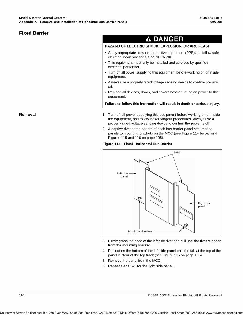
Model 6 Motor Control Centers 80459-641-01DAppendix A—Removal and Installation of Horizontal Bus Barrier Panels 09/2008
© 1999–2008 Schneider Electric All Rights Reserved104
Fixed Barrier
Removal 1. Turn off all power supplying this equipment before working on or inside the equipment, and follow lockout/tagout procedures. Always use a properly rated voltage sensing device to confirm the power is off.
2. A captive rivet at the bottom of each bus barrier panel secures the panels to mounting brackets on the MCC (see Figure 114 below, and Figures 115 and 116 on page 105).
3. Firmly grasp the head of the left side rivet and pull until the rivet releases from the mounting bracket.
4. Pull out on the bottom of the left side panel until the tab at the top of the panel is clear of the top track (see Figure 115 on page 105).
5. Remove the panel from the MCC.6. Repeat steps 3–5 for the right side panel.
DANGERHAZARD OF ELECTRIC SHOCK, EXPLOSION, OR ARC FLASH
• Apply appropriate personal protective equipment (PPE) and follow safe electrical work practices. See NFPA 70E.
• This equipment must only be installed and serviced by qualified electrical personnel.
• Turn off all power supplying this equipment before working on or inside equipment.
• Always use a properly rated voltage sensing device to confirm power is off.
• Replace all devices, doors, and covers before turning on power to this equipment.
Failure to follow this instruction will result in death or serious injury.
Figure 114: Fixed Horizontal Bus Barrier
Plastic captive rivets
Right side panel
Left sidepanel
Tabs
Courtesy of Steven Engineering, Inc.-230 Ryan Way, South San Francisco, CA 94080-6370-Main Office: (650) 588-9200-Outside Local Area: (800) 258-9200-www.stevenengineering.com
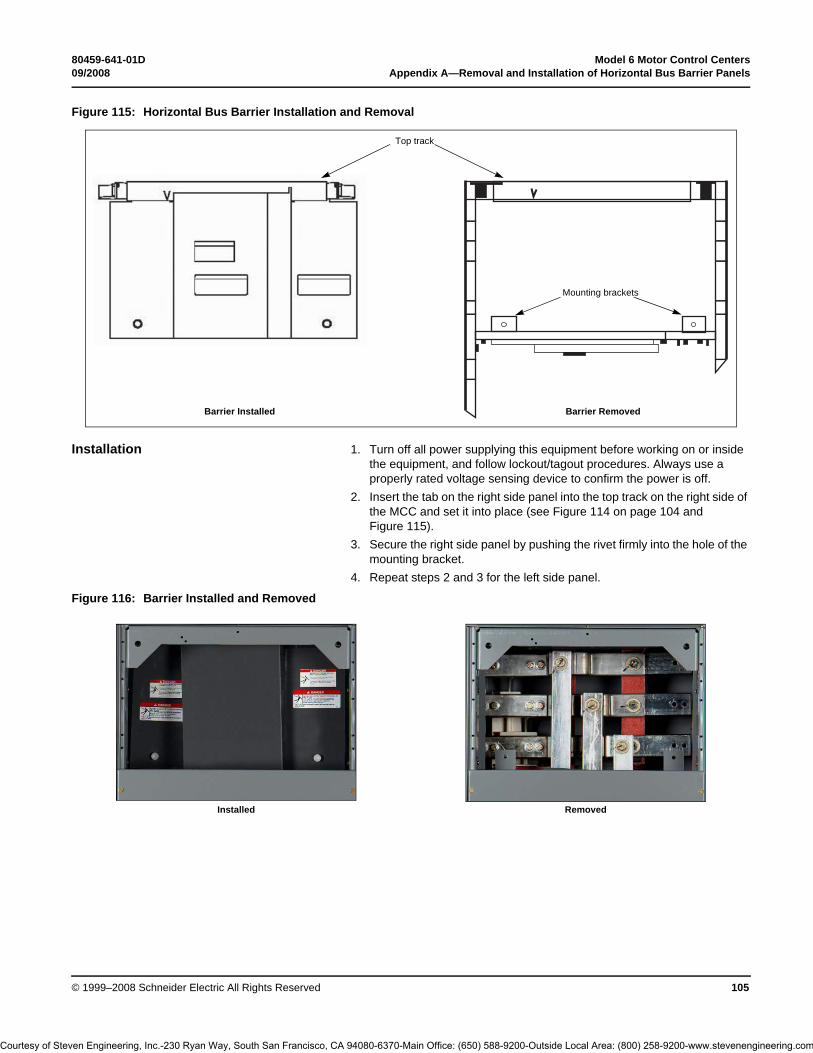
80459-641-01D Model 6 Motor Control Centers09/2008 Appendix A—Removal and Installation of Horizontal Bus Barrier Panels
© 1999–2008 Schneider Electric All Rights Reserved 105
Installation 1. Turn off all power supplying this equipment before working on or inside the equipment, and follow lockout/tagout procedures. Always use a properly rated voltage sensing device to confirm the power is off.
2. Insert the tab on the right side panel into the top track on the right side of the MCC and set it into place (see Figure 114 on page 104 and Figure 115).
3. Secure the right side panel by pushing the rivet firmly into the hole of the mounting bracket.
4. Repeat steps 2 and 3 for the left side panel.
Figure 115: Horizontal Bus Barrier Installation and Removal
Mounting brackets
Top track
Barrier Installed Barrier Removed
Figure 116: Barrier Installed and Removed
Installed Removed
Courtesy of Steven Engineering, Inc.-230 Ryan Way, South San Francisco, CA 94080-6370-Main Office: (650) 588-9200-Outside Local Area: (800) 258-9200-www.stevenengineering.com

Model 6 Motor Control Centers 80459-641-01DAppendix B—Non-Conductive Horizontal Bus Barrier Retrofit Kit 09/2008
© 1999–2008 Schneider Electric All Rights Reserved106
Appendix B—Non-Conductive Horizontal Bus Barrier Retrofit Kit
This appendix contains installation instructions for non-conductive horizontal bus barrier retrofit kits manufactured by Schneider Electric. These kits are for use in 15 in. (381 mm) and 20 in. (508 mm) deep Models 5 and 6 Motor Control Centers.
DANGERHAZARD OF ELECTRIC SHOCK, EXPLOSION, OR ARC FLASH
• Apply appropriate personal protective equipment (PPE) and follow safe electrical work practices. See NFPA 70E.
• This equipment must only be installed and serviced by qualified electrical personnel.
• Turn off all power supplying this equipment before working on or inside equipment.
• Always use a properly rated voltage sensing device to confirm power is off.
• After removing rivets and screws, verify that the compartment is free of loose particles.
• Replace all devices, doors, and covers before turning on power to this equipment.
Failure to follow this instruction will result in death or serious injury.
Figure 117: Retrofit Kit Components
2 screws [1/4 x 20 x 1/2 in. (6 x 508 x 13 mm)] 20 in. (508 mm) deep MCC retrofit kits only.
14 rivets [1/8 in. (3 mm]Only 12 are needed
Panels
Top retrofit track
Endcap
Bottom track for relay topshelf assemblies
Bottom retrofit bracket for relay topshelf assemblies (must not be riveted together before installation)
Bottom track and retrofit bracket for welded topshelf assemblies (must be riveted together before installation)
Top retrofit bracket
Endcap
Top retrofit bracket
Courtesy of Steven Engineering, Inc.-230 Ryan Way, South San Francisco, CA 94080-6370-Main Office: (650) 588-9200-Outside Local Area: (800) 258-9200-www.stevenengineering.com

80459-641-01D Model 6 Motor Control Centers09/2008 Appendix B—Non-Conductive Horizontal Bus Barrier Retrofit Kit
© 1999–2008 Schneider Electric All Rights Reserved 107
Remove Existing Components Follow these instructions to remove the existing top horizontal wireway cover, bus barriers, units below the topshelf, and brackets [15 in. (381 mm) deep MCC]:
Horizontal Wireway Cover 1. Turn off all power supplying this equipment before working on or inside the equipment, and follow lockout/tagout procedures. Always use a properly rated voltage sensing device to confirm power is off.
2. Remove the screws that secure the top horizontal wireway cover to the structure, and then remove the cover.
Horizontal Bus Barriers 1. Remove the screw located at the top of the two-piece bus barriers.2. Remove the screw located at the bottom of the two-piece bus barriers.3. Pull the two metal barriers out of the MCC and discard them.
Units Below the Topshelf If applicable, remove the plug-in unit below the topshelf (see Figure 118).
Refer to either the Model 5 MCC Installation and Maintenance Manual (# 8998IM9101R5/92) or “Removing the Control Unit” on page 48 of this bulletin for unit removal instructions. If necessary, contact your local Schneider Electric field sales representative to obtain this bulletin.
Existing Brackets: 15 in. (381 mm) Deep MCC Only
If the MCC is 15 in. (381 mm) deep, use a 1/8 in. (3 mm) drill bit to remove the rivets that hold the right and left horizontal bus barrier brackets in place (see Figure 118). Discard the brackets after removal.
NOTE: Discard all retrofit brackets if the existing bus barrier bracket “B” (see Figure 118) is present on the 15 in. (381 mm) deep MCC. All holes are already present for direct mounting of the horizontal bus barrier.
DANGERHAZARD OF ELECTRIC SHOCK, EXPLOSION, OR ARC FLASH
Drilling increases the chance of loose particles in the MCC. Confirm that the compartment is free of loose particles before turning on power to this equipment.
Failure to follow this instruction will result in death or serious injury.
Figure 118: Remove Existing Brackets on the 15 in. (381 mm) Deep MCC
Topshelf
Detail
Side of MCC
Rivets
Side channel
Existing bus barrierbracket
Black grommet
Existing bus barrier brackets
Bracket A Bracket B
Detail
Courtesy of Steven Engineering, Inc.-230 Ryan Way, South San Francisco, CA 94080-6370-Main Office: (650) 588-9200-Outside Local Area: (800) 258-9200-www.stevenengineering.com

Model 6 Motor Control Centers 80459-641-01DAppendix B—Non-Conductive Horizontal Bus Barrier Retrofit Kit 09/2008
© 1999–2008 Schneider Electric All Rights Reserved108
Install the Retrofit Kit
Retrofit Brackets and Endcaps Follow the applicable instructions below to install retrofit brackets into 15 in. (381 mm) or 20 in. (508 mm) deep MCCs. The top retrofit bracket must sit flush against the side channel. Slide the black grommets toward the back of the MCC.
• 15 in. (381 mm) deep MCC: Use a rivet gun and two rivets in the retrofit kit to attach the retrofit brackets to the left and right side channels (see Figure 119).
• 20 in. (508 mm) deep MCC: Use the screws provided in the retrofit kit to attach the retrofit brackets to the left and right side channels. Align the holes in the bracket and side channel as shown in Figure 120 on page 109.
NOTES: • Even if the holes are present for a direct mounting of the endcap to the side channels, use the top retrofit bracket on 20 in. (508 mm) deep MCCs.
• Before tightening the screws, push the bracket away from you so that the rear bracket hole is properly aligned with the side channel hole.
Figure 119: 15 in. (381 mm) Deep MCC Retrofit Bracket
Top retrofit bracket
Topshelf
Side channel
Rivets
Courtesy of Steven Engineering, Inc.-230 Ryan Way, South San Francisco, CA 94080-6370-Main Office: (650) 588-9200-Outside Local Area: (800) 258-9200-www.stevenengineering.com

80459-641-01D Model 6 Motor Control Centers09/2008 Appendix B—Non-Conductive Horizontal Bus Barrier Retrofit Kit
© 1999–2008 Schneider Electric All Rights Reserved 109
Follow the steps below to install the endcaps (see Figure 121).
1. Rivet one endcap into place on the retrofit bracket or the side channel, either to the right or left side of the structure.
2. Insert one end of the top track into the attached endcap. 3. Place the other endcap on the opposite end of the top track, and slide
the top track into place. 4. Rivet the second endcap to the retrofit bracket.
Figure 120: 20 in. (508 mm) Deep MCC Retrofit Bracket
Topshelf
Top retrofit bracket Screw(1/4 x 20 x 1/2 in.)
Side channel
Figure 121: Endcap Placement
Rivets
Detail
Endcap
Top retrofit bracket
See Detail
Side channel
Topshelf
Courtesy of Steven Engineering, Inc.-230 Ryan Way, South San Francisco, CA 94080-6370-Main Office: (650) 588-9200-Outside Local Area: (800) 258-9200-www.stevenengineering.com

Model 6 Motor Control Centers 80459-641-01DAppendix B—Non-Conductive Horizontal Bus Barrier Retrofit Kit 09/2008
© 1999–2008 Schneider Electric All Rights Reserved110
Bottom Track and Bottom Retrofit Bracket
1. Using a 1/8 in. (3 mm) drill bit, drill out both of the rivets on the horizontal bus barrier bracket (the L-shaped bracket located on the topshelf—see Figure 122). Remove the bracket and discard it.
2. To install the bottom retrofit track, follow step a if you have a welded topshelf, or step b if you have a relay topshelf (see Figure 123):
a. Welded topshelf: Align the holes of the shelf with those on the bottom track (see Figure 123). Rivet the track and the retrofit bracket to the topshelf. NOTE: If the bus contains four laminations, access the rivet holes from underneath the topshelf.
b. Relay topshelf: Align the two holes on the relay shelf with the bottom retrofit bracket holes (see Figure 123). Mark the places where you will drill other holes to secure the bottom track to the shelf. Drill the holes using a drill bit ranging from 0.136 in.–0.147 in. (3 mm–4 mm) in diameter. Rivet the track and retrofit bracket to the topshelf. NOTE: The bottom retrofit track can be riveted directly onto the relay topshelf only if the relay assembly topshelf has two holes instead of four.
Figure 122: Horizontal Bus Barrier (L-shaped) Bracket
Horizontal bus barrier bracket
Figure 123: Welded and Relay Topshelf Assemblies
Welded Topshelf
Bottom retrofit bracket and bottom retrofit track
Bottom retrofit bracket
Bottom retrofit track
Relay Topshelf
Rivets
Four holes
Courtesy of Steven Engineering, Inc.-230 Ryan Way, South San Francisco, CA 94080-6370-Main Office: (650) 588-9200-Outside Local Area: (800) 258-9200-www.stevenengineering.com

80459-641-01D Model 6 Motor Control Centers09/2008 Appendix B—Non-Conductive Horizontal Bus Barrier Retrofit Kit
© 1999–2008 Schneider Electric All Rights Reserved 111
Left and Right Panels
Installation NOTE: The horizontal bus barrier contains two identical panels with arrows at the top. The “handle” on the left panel faces the front of the MCC section. The “handle cavity” on the right panel faces the front of the MCC section (see Figure 124).
1. Align the arrows on the right panel and top track as shown in Figure 125.2. Lift the panel up into the rear groove of the top track.3. Lower the panel into the rear groove of the bottom track.4. Slide the panel to the far right.5. Align the arrows on the left panel and top track.6. Repeat Steps 2 and 3 using the left panel and front groove.7. Slide the panel to the left until it locks (snaps) into place.8. Verify that the barrier is completely closed by making sure that the wiring
compartment is isolated from the bus compartment.
Figure 124: Right Panel (Side View)
Figure 125: Installing the Right Panel into the Rear Groove
Wireway Area Horizontal Bus Area
Horizontal bus barrier - right panel
Handle
Rear groove
Front of section
Handle cavity
Front groove
Right panelSnap
Top trackEndcap
Rear groove
Flange points away from MCC
Courtesy of Steven Engineering, Inc.-230 Ryan Way, South San Francisco, CA 94080-6370-Main Office: (650) 588-9200-Outside Local Area: (800) 258-9200-www.stevenengineering.com

Model 6 Motor Control Centers 80459-641-01DAppendix B—Non-Conductive Horizontal Bus Barrier Retrofit Kit 09/2008
© 1999–2008 Schneider Electric All Rights Reserved112
Removal (when required) 1. With one hand, slide the left panel to the right until it unsnaps from the right panel.
2. Align the arrows on the left panel and top track as shown in Figure 126. Lift the panel out of the bottom track, and remove the panel.
3. Align the arrows on the right panel and top track as shown in Figure 126. Lift the panel out of the bottom track, and remove the panel.
Replace Components
Follow the steps below to replace the components of the MCC.
1. Install the unit you removed in the section, “Units Below the Topshelf” on page 107. Refer to either the Model 5 MCC Installation and Maintenance Manual (# 8998IM9101R5/92) or “Removing the Control Unit” on page 48 of this bulletin for instructions on installing units in an MCC.
2. Replace the top horizontal wireway cover.3. Replace or close all other covers or doors before turning on the power to
the MCC.
Figure 126: Aligning the Arrows on the Panels
Align arrows
Lift up on panel
DANGERHAZARD OF ELECTRIC SHOCK, EXPLOSION, OR ARC FLASH
• Apply appropriate personal protective equipment (PPE) and follow safe electrical work practices. See NFPA 70E.
• This equipment must only be installed and serviced by qualified electrical personnel.
• Turn off all power supplying this equipment before working on or inside equipment.
• Always use a properly rated voltage sensing device to confirm power is off.
• Replace all devices, doors, and covers before turning on power to this equipment.
Failure to follow this instruction will result in death or serious injury.
Courtesy of Steven Engineering, Inc.-230 Ryan Way, South San Francisco, CA 94080-6370-Main Office: (650) 588-9200-Outside Local Area: (800) 258-9200-www.stevenengineering.com

80459-641-01D Model 6 Motor Control Centers09/2008 Appendix C—Automatic Vertical Bus Shutter
© 1999–2008 Schneider Electric All Rights Reserved 113
Appendix C—Automatic Vertical Bus Shutter
IntroductionTheautomatic vertical bus shutter is an optional feature for the Model 6 motor control center (MCC) vertical bus. The shutters are pre-assembled and installed as part of the MCC line-up.
Automatic bus shutters open and close the vertical bus connection point when units are inserted and removed from the structure. The shutters can be located throughout the MCC and placed in 6 in. (152 mm) increments. They mount to the left edge of each midshelf.
The automatic shutter assembly requires an updated midshelf to allow clearance for the shutter above the plug-in unit.
NOTES: • MCC structures shipped before January 2003 cannot use the top 3-in. (76 mm) space with the automatic vertical bus shutter option. A 3-in. (76 mm) cover plate is required to cover the opening.
• Compac™ 6 control units shipped before January 2003 cannot be used with the automatic vertical bus shutter option.
• Variable frequency drive and soft starter units 45 in. or taller that shipped before July 2003 with a side-panel opening as shown in Figure 127A, require an auto-shutter cover (Square D Seneca part #80451-765-01). The auto-shutter cover aligns with the back edge of the center-most flat head screw as shown in Figure 127B.
There are four main components of the automatic vertical bus shutter (see Figure 128 on page 114):
1. Operator Mechanism: Operates the vertical bus shutter, allowing the plug-in unit to engage the vertical bus.
2. Mechanism Housing: Protects the mechanism from incidental foreign material that could obstruct the intended operation.
DANGERHAZARD OF ELECTRIC SHOCK, EXPLOSION, OR ARC FLASH
• Apply appropriate personal protective equipment (PPE) and follow safe electrical work practices. See NFPA 70E.
• This equipment must only be installed and serviced by qualified electrical personnel.
• Turn off all power supplying this equipment before working on or inside equipment.
• Always use a properly rated voltage sensing device to confirm power is off.
• Replace all devices, doors, and covers before turning on power to this equipment.
Failure to follow this instruction will result in death or serious injury.
Figure 127: Location of Auto-Shutter Cover for Side-Panel Opening
Side panel opening
Auto-shutter cover
127A 127B
Courtesy of Steven Engineering, Inc.-230 Ryan Way, South San Francisco, CA 94080-6370-Main Office: (650) 588-9200-Outside Local Area: (800) 258-9200-www.stevenengineering.com

Model 6 Motor Control Centers 80459-641-01DAppendix C—Automatic Vertical Bus Shutter 09/2008
© 1999–2008 Schneider Electric All Rights Reserved114
3. Vertical Bus Door and Clip: Provides a barrier against incidental contact with the MCC vertical bus.
4. Manual Shutter: Prevents access to the unused vertical bus openings. The manual shutter is held in place by a built-in locking feature that holds the shutter in the closed position during shipping, set-up, and daily operations.
Compare the field-installed midshelf to the two designs above. If the field-installed midshelf matches Style 1, follow the installation and removal instructions starting below. If the field-installed midshelf matches Style 2, follow the instructions starting on page 117.
Installation—Style 1Follow these instructions to install the automatic vertical bus shutter assembly (see Figure 130 on page 115) to an existing Style 1 midshelf:
1. Turn off all power supplying this equipment before working on or inside the equipment, and follow lockout/tagout procedures. Always use a properly rated voltage sensing device to confirm the power is off.
2. Position the midshelf (Figure 129, Item A on page 115) in the appropriate area of the structure.
3. Place the mounting foot (Item B) of the shelf into the mounting pan slots (Item C). Secure the shelf on the left and right with flat head screws (Detail A, Item D).
4. Install the hinge leaves (Detail A, Item E) and the door (Item F) into the hinge slots (Item G), which are on the structure corner channel. Fasten the hinge leaves to the structure corner channel using hex head screws (Item H).
5. Install the quarter turn fastener receptacles (Detail B, Item J) into the bracket slots (Item K) and fasten with hex head screws (Item H).
6. Install the automatic bus shutter assembly by rotating the mechanism housing upward to clear the front corner channel of the structure.
7. Slide the automatic shutter assembly upward so that it fits snugly to the left edge of the midshelf.
8. Loosely insert the two 10-32 x 3/8 in. mounting screws through the inner left edge of the midshelf and into the square nuts in the housing.
Figure 128: Automatic Vertical Bus Shutter in an MCC (front view)
3
4
2
1
Style 1 Style 2
DANGERHAZARD OF ELECTRIC SHOCK, EXPLOSION, OR ARC FLASH
• Apply appropriate personal protective equipment (PPE) and follow safe electrical work practices. See NFPA 70E.
• This equipment must be installed and serviced only by qualified electrical personnel.
• Turn off all power supplying this equipment before working on or inside.
• Always use a properly rated voltage sensing device to confirm power is off.
• Replace all devices, doors, and covers before turning on power to this equipment.
Failure to follow this instruction will result in death or serious injury.
Courtesy of Steven Engineering, Inc.-230 Ryan Way, South San Francisco, CA 94080-6370-Main Office: (650) 588-9200-Outside Local Area: (800) 258-9200-www.stevenengineering.com

80459-641-01D Model 6 Motor Control Centers09/2008 Appendix C—Automatic Vertical Bus Shutter
© 1999–2008 Schneider Electric All Rights Reserved 115
9. Remove the manual shutter from the vertical bus assembly. Allow the manual shutter to hang next to the vertical bus assembly.
10. Snap the automatic shutter rod onto the vertical bus clip located on the front of the vertical bus assembly.
11. Tighten the two 10-32 x 3/8 in. mounting screws inserted in Step 8.12. Push the operator mechanism to the rear, ensuring the shutter rotates
upward into the pocket of the midshelf above the unit.13. Insert the unit into the MCC. Follow the procedures in “Section 4—
Installing the MCC”.14. Replace all devices, doors, and covers before turning on the power to
the equipment.
Figure 129: Shelf Installation—Style 1
Table 17: Shelf Installation Kit Parts—Style 1
Description Quantity Item
Midshelf 1➀ A
Flat head screws 2 D
Unit door 1 F
Hex head screws 4 ➁ H
Quarter turn fastener receptacle 2 ➁ J
➀ Shelf is furnished with order, and may already be mounted in position.
➁ All necessary hardware for typical shelf installation is included. Door installation may require additional hardware.
H
J
K F
BB
F GG
E
D
F
Detail A
Detail B
See Detail A
See Detail B
See Detail A or B
Figure 130: Automatic Vertical Bus Shutter Installation—Style 1
Vertical bus door and rod
Midshelf
Operator mechanism
Mechanismhousing
Mountingscrews
Manualshutters Vertical bus
assembly
Courtesy of Steven Engineering, Inc.-230 Ryan Way, South San Francisco, CA 94080-6370-Main Office: (650) 588-9200-Outside Local Area: (800) 258-9200-www.stevenengineering.com

Model 6 Motor Control Centers 80459-641-01DAppendix C—Automatic Vertical Bus Shutter 09/2008
© 1999–2008 Schneider Electric All Rights Reserved116
Removal—Style 1 Follow these instructions to remove the automatic vertical bus shutter assembly (see Figure 131) from an existing Style 1 midshelf.
1. Turn off all power supplying this equipment before working on or inside the equipment, and follow lockout/tagout procedures. Always use a properly rated voltage sensing device to confirm the power is off.
2. Remove the unit from the MCC structure. Follow the procedures in “Section 4—Installing the MCC”.
3. Remove the automatic vertical bus shutter rod from the vertical bus clip located on the front of the vertical bus assembly.
4. Insert the manual shutter into the vertical bus assembly.5. Remove the two 10-32 x 3/8 in. mounting screws located on the inner
left edge of the midshelf.6. Slide the automatic shutter assembly downward, clearing the midshelf.7. Rotate the assembly downward to clear the front corner channel of the
structure.8. Remove the automatic shutter assembly.9. Replace all devices, doors, and covers before turning on the power to
the equipment.
DANGERHAZARD OF ELECTRIC SHOCK, EXPLOSION, OR ARC FLASH
• Apply appropriate personal protective equipment (PPE) and follow safe electrical work practices. See NFPA 70E.
• This equipment must be installed and serviced only by qualified electrical personnel.
• Turn off all power supplying this equipment before working on or inside.
• Always use a properly rated voltage sensing device to confirm power is off.
• Replace all devices, doors, and covers before turning on power to this equipment.
Failure to follow this instruction will result in death or serious injury. Figure 131: Automatic Vertical Bus Shutter Removal—Style 1
Vertical bus door and rod
Midshelf
Operator mechanism
Mechanismhousing
Mountingscrews
Manualshutters
Vertical bus assembly
Courtesy of Steven Engineering, Inc.-230 Ryan Way, South San Francisco, CA 94080-6370-Main Office: (650) 588-9200-Outside Local Area: (800) 258-9200-www.stevenengineering.com

80459-641-01D Model 6 Motor Control Centers09/2008 Appendix C—Automatic Vertical Bus Shutter
© 1999–2008 Schneider Electric All Rights Reserved 117
Installation—Style 2Follow these instructions to install the automatic vertical bus shutter assembly (see Figure 133 on page 118) to an existing Style 2 midshelf (see Figure 128 on page 114):
1. Turn off all power supplying this equipment before working on or inside the equipment, and follow lockout/tagout procedures. Always use a properly rated voltage sensing device to confirm the power is off.
2. Position the midshelf (Figure 132, Item A) in the appropriate area of the structure.
3. Place the mounting foot (Item B) of the shelf into the mounting pan slots (Item C). Secure the shelf at the mounting foot end, the left side, and the right side with flat head screws (Detail A, Item D).
4. Install the hinge leaves of the door (Detail A, Item E) into the hinge slots (Item G), which are on the structure corner channel. Fasten the hinge leaves to the structure corner channel using hex head screws (Item H).
5. Install quarter-turn fastener receptacles (Detail B, Item J) into the bracket slots (Item K) and fasten with hex head screws (Item H).
6. Install the automatic bus shutter assembly by rotating the mechanism housing upward to clear the front corner channel of the structure.
7. Slide the automatic shutter assembly upward so that it fits snugly to the left edge of the midshelf.
8. Loosely insert a 10-32 x 3/8 in. mounting screw through the inner left edge of the midshelf and into the square nuts in the housing.
DANGERHAZARD OF ELECTRIC SHOCK, EXPLOSION, OR ARC FLASH
• Apply appropriate personal protective equipment (PPE) and follow safe electrical work practices. See NFPA 70E.
• This equipment must be installed and serviced only by qualified electrical personnel.
• Turn off all power supplying this equipment before working on or inside.
• Always use a properly rated voltage sensing device to confirm power is off.
• Replace all devices, doors, and covers before turning on power to this equipment.
Failure to follow this instruction will result in death or serious injury.
Figure 132: Shelf Installation—Style 2
A
BC
D
F
FE
GD
H
JH
K
F
Table 18: Shelf Installation Kit Parts—Style 2
Description Quantity Item
Midshelf 2➀ A
Flat head screws 3 D
Unit door 1 F
Hex head screws 4➁ H
Quarter turn fastener receptacle 2➁ J
➀ Shelves are furnished with order. Structure may already have shelf mounted in position.
➁ All necessary hardware for typical shelf installation is included. Door installation may require additional hardware.
See Detail A
Detail A
See DetailA or B
See Detail B
Detail B
Courtesy of Steven Engineering, Inc.-230 Ryan Way, South San Francisco, CA 94080-6370-Main Office: (650) 588-9200-Outside Local Area: (800) 258-9200-www.stevenengineering.com
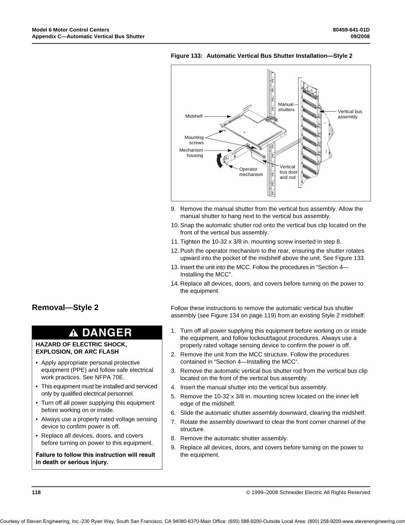
Model 6 Motor Control Centers 80459-641-01DAppendix C—Automatic Vertical Bus Shutter 09/2008
© 1999–2008 Schneider Electric All Rights Reserved118
9. Remove the manual shutter from the vertical bus assembly. Allow the manual shutter to hang next to the vertical bus assembly.
10. Snap the automatic shutter rod onto the vertical bus clip located on the front of the vertical bus assembly.
11. Tighten the 10-32 x 3/8 in. mounting screw inserted in step 8.12. Push the operator mechanism to the rear, ensuring the shutter rotates
upward into the pocket of the midshelf above the unit. See Figure 133.13. Insert the unit into the MCC. Follow the procedures in “Section 4—
Installing the MCC”.14. Replace all devices, doors, and covers before turning on the power to
the equipment.
Removal—Style 2 Follow these instructions to remove the automatic vertical bus shutter assembly (see Figure 134 on page 119) from an existing Style 2 midshelf:
1. Turn off all power supplying this equipment before working on or inside the equipment, and follow lockout/tagout procedures. Always use a properly rated voltage sensing device to confirm the power is off.
2. Remove the unit from the MCC structure. Follow the procedures contained in “Section 4—Installing the MCC”.
3. Remove the automatic vertical bus shutter rod from the vertical bus clip located on the front of the vertical bus assembly.
4. Insert the manual shutter into the vertical bus assembly.5. Remove the 10-32 x 3/8 in. mounting screw located on the inner left
edge of the midshelf.6. Slide the automatic shutter assembly downward, clearing the midshelf.7. Rotate the assembly downward to clear the front corner channel of the
structure.8. Remove the automatic shutter assembly.9. Replace all devices, doors, and covers before turning on the power to
the equipment.
Figure 133: Automatic Vertical Bus Shutter Installation—Style 2
Vertical bus door and rod
Midshelf
Operator mechanism
Mechanismhousing
Mountingscrews
Manual shutters Vertical bus
assembly
DANGERHAZARD OF ELECTRIC SHOCK, EXPLOSION, OR ARC FLASH
• Apply appropriate personal protective equipment (PPE) and follow safe electrical work practices. See NFPA 70E.
• This equipment must be installed and serviced only by qualified electrical personnel.
• Turn off all power supplying this equipment before working on or inside.
• Always use a properly rated voltage sensing device to confirm power is off.
• Replace all devices, doors, and covers before turning on power to this equipment.
Failure to follow this instruction will result in death or serious injury.
Courtesy of Steven Engineering, Inc.-230 Ryan Way, South San Francisco, CA 94080-6370-Main Office: (650) 588-9200-Outside Local Area: (800) 258-9200-www.stevenengineering.com

80459-641-01D Model 6 Motor Control Centers09/2008 Appendix C—Automatic Vertical Bus Shutter
© 1999–2008 Schneider Electric All Rights Reserved 119
Operation—Styles 1 and 2
Inserting a Unit When a unit is inserted into the Model 6 MCC structure, the operator mechanism opens the automatic bus shutter, allowing the unit stabs to connect with the vertical bus.
Removing a Unit The automatic shutter will close when a unit is removed from the structure. The shutter door provides a barrier against incidental contact with the MCC vertical bus.
Figure 134: Automatic Vertical Bus Shutter Removal—Style 2
Vertical bus door and rod
Midshelf
Operator mechanism
Mechanismhousing
Mountingscrews
Manual shutters Vertical bus
assembly
Courtesy of Steven Engineering, Inc.-230 Ryan Way, South San Francisco, CA 94080-6370-Main Office: (650) 588-9200-Outside Local Area: (800) 258-9200-www.stevenengineering.com

Model 6 Motor Control Centers 80459-641-01DAppendix D—Technical Support 09/2008
© 1999–2008 Schneider Electric All Rights Reserved120
Appendix D—Technical Support
The Model 6 Motor Control Center incorporates many Schneider Electric products within one package. Following are the Technical Support numbers for some of these products:
Device Name Location Technical Support No.
Motor Control Centers1
1 The MCC Technical Assistance Group is your first point of contact for any MCC questions. Or, contact your local distributor/Schneider Electric field sales office.
Seneca, SC: MCC Technical Assistance Group (TAG)
(800) 634-2003
PowerLogic® EquipmentSMS-3000 Software
La Vergne, TN: PowerLogic Technical Assistance
(615) 287-3400
Variable Frequency DrivesSoft StartersStarters/Contactors/Overloads
Raleigh, NC: Raleigh Help Desk (919) 266-8600
Schneider Automation Equipment and Software
North Andover, MA: Customer Central
(800) 468-5342
Industrial Application Team Raleigh, NC (800) 468-5342
Field Services Organization Support Florence, KY (800) 634-2003
Courtesy of Steven Engineering, Inc.-230 Ryan Way, South San Francisco, CA 94080-6370-Main Office: (650) 588-9200-Outside Local Area: (800) 258-9200-www.stevenengineering.com

80459-641-01D Model 6 Motor Control Centers09/2008 Index
© 1999–2008 Schneider Electric All Rights Reserved 121
En
glis
h
AAltistart 48 80Altivar 61/71 80automatic bus shutters 55, 113–119
Bbarriers 55, 106
bus 16, 30–32, 34, 46, 102–103, 111fixed 104–105non-conductive 106
insulating 25–26, 28wireway 65, 85
bus barriers 16, 30–32, 34, 46, 102–103, 111
fixed 104–105non-conductive 106
bus bars 16, 46maintenance 46
bus connection torque values 46, 58bus shutters
automatic 55, 113–119manual 55, 85
Ccabling
iMCC 66, 71circuit breakers 53, 63, 100Compac 6 51, 55, 59–60, 82, 85–86, 88,
113maintenance 52removal 51
conduit entry 37conical washers 31, 36control units 9, 47
installation 88maintenance 47, 52removal 48, 50–51replacement 88
control wiring 40, 86
Eenclosures 15, 25, 46
NEMA Type 1 16, 30, 33–34NEMA Type 1 Gasketed 16, 23NEMA Type 12 16, 23, 30, 33–34NEMA Type 3R 25, 28–29, 32–33types 13
expansion 82
Ffixed bus barriers 104–105fuse clips 53, 87fuses 53, 87fusible switches 53, 100
Gground bus torque values 46, 58
Hhandling 12hinge pins 50horizontal bus covers 30, 32, 34horizontal wire trough 16, 37, 40, 46
IiMCC 65
cabling 66, 71communications 71
incoming line 40, 46, 58insulating barriers 25–26, 28insulation tests 56intelligent MCC 65interlocks 48–49, 52, 58, 63, 88
starter 54
Lload wiring 86
MMag-Gard 63–64maintenance 44, 46, 70
after a fault 57bus bars 46Compac 6 52control units 47incoming line 46log 101special units 55
manual bus shutters 55, 85motor circuit protectors 63–64Motor Logic 44, 59, 61–62
overload relay size 61retrofit applications 60torque values 61troubleshooting 91
Motor Logic Plus 70local programming 72remote programming 73
motor protection relays 70
NNEMA Type 1 enclosures
ground bus splicing 33joining 16power bus splicing 30, 34seismic tie-down locations 20
NEMA Type 1 Gasketed enclosuresjoining 16seismic tie-down locations 20splice gaskets 23
NEMA Type 12 enclosuresground bus splicing 33joining 16power bus splicing 30, 34seismic tie-down locations 20splice gaskets 23
NEMA Type 3R enclosures 25ground bus splicing 33joining 28–29power bus splicing 32seismic tie-down locations 21
non-conductive bus barriers 106
Ooperator mechanisms 44, 48, 53, 58, 70,
100overload relays 44, 54, 58–63
troubleshooting 90–91
PPowerLogic 80
technical support 120PowerLogic units 70PowerPact 63–64, 100pre-operation checklist 44
Rreceiving 12resistance measurements 56retrofit applications 60, 78
Sseismic tie-down locations
NEMA Type 1, Type 1 Gasketed, and Type 12 20
NEMA Type 3R 21shipping weights 13six-inch units 51, 60, 86–87solid-state overload relays 59space requirements 15special units 55splice assemblies 30, 36splice gaskets 23splicing
bus 30, 32–33ground bus 15power bus 30, 32, 34
stab assembly 52starter contacts 53starter interlocks 54
Ttechnical support 120terminal blocks 40, 48–49, 52, 60, 66, 78,
86TeSys T 10, 44, 70, 77–79, 91–92
troubleshooting 91thermal overload
relaystroubleshooting 90
selection data 42unit selection 94
torque values 87bus connection 46, 58ground bus 46, 58main lug compartments 42Motor Logic 61
troubleshooting procedures 89twin handle cam mechanism 49
Vvertical wire trough 40, 42, 49, 52, 54, 82,
85–86, 88
Wwire trough 9
horizontal 16, 37, 40, 46vertical 40, 42, 49, 52, 54, 82, 85–86,
88wireway barriers 65, 85wiring 40
Courtesy of Steven Engineering, Inc.-230 Ryan Way, South San Francisco, CA 94080-6370-Main Office: (650) 588-9200-Outside Local Area: (800) 258-9200-www.stevenengineering.com

Notes
Courtesy of Steven Engineering, Inc.-230 Ryan Way, South San Francisco, CA 94080-6370-Main Office: (650) 588-9200-Outside Local Area: (800) 258-9200-www.stevenengineering.com

Courtesy of Steven Engineering, Inc.-230 Ryan Way, South San Francisco, CA 94080-6370-Main Office: (650) 588-9200-Outside Local Area: (800) 258-9200-www.stevenengineering.com

Electrical equipment should be installed, operated, serviced, and maintained only by qualified personnel. No responsibility is assumed by Schneider Electric for any consequences arising out of the use of this material.80459-641-01D 09/2008Replaces 80459-641-01C 06/2006© 1999–2008 Schneider Electric All Rights Reserved
Schneider Electric USA1990 Sandifer Blvd.Seneca, SC 29678 USA1-888-SquareD (1-888-778-2733)www.schneider-electric.us
Model 6 Motor Control CentersInstruction Bulletin
Courtesy of Steven Engineering, Inc.-230 Ryan Way, South San Francisco, CA 94080-6370-Main Office: (650) 588-9200-Outside Local Area: (800) 258-9200-www.stevenengineering.com