Embed Size (px)
Citation preview

Full lift safety valvewith spring loading.
(AIT)
The valve works as an automatic pressure releasing regulator activated by the static pressure existing at the entrance to the valve and is characterized by its ability to open instantly and totally.
Design in accordance with “International Standard ISO 4126-1 Safety Valves”.In accordance with the requirements of the pressure equipment directive 2014/68/EU.EC valve verification certified by: TÜV Internacional Grupo TÜV Rheinland, S.L. EC 0035. Type (Module D) EC examination report nº 33530455 certified by: TÜV Internacional Grupo TÜV Rheinland, S.L. In compliance with the ATEX 2014/34/EU directive “Protective equipment and systems for use in potentially explosive atmospheres”.Other authorisations: ISCIR, ITI, NASTHOL,EAC,...etc.
Specifications — 90° angular flow.— Activated by direc ed for their resistance to corrosion. With the exception of washers and couplings, the valves are
free of non-ferric materials.— Internal body designed to offer favourable flow profile.— Sealing surfaces treated and balanced, making them extremely tightness, even exceeding EN 12266-1 requeriments.— Great discharge capacity. For liquids typically used with openings similar to proportional safety valves.— Equipped with draining screws for removing condensation.— Auto-centering plug.— Threaded shaft with lever positioner facilitating immediate manual action.— Elevator, independent of the seal, designed facilitate sudden opening when the steam expands and, with any fluid,
guarantees absolute opening and closing precision.— All the valves are supplied sealed at the set pressure requested, simulating operational conditions, and are vigorously
tested.— All components are numbered, registered and checked. If requested in advance, material, casting, test and efficiency
certificates will be enclosed with the valve, and the instruction manual, in accordance with P.E.D. 2014/68/EU.
EN
Model 596
EP ESAP CP

N.º PIECE PIECEMATERIAL
CAST STEEL STAINLESS STEEL1 Body Cast steel (EN-1.0619+N) Stainless steel (EN-1.4408)2 Closed bell Nodular iron (EN-5.3106) Stainless steel (EN-1.4408)3 Open bell Cast steel (EN-1.0619+N) Stainless steel (EN-1.4408)
4, 5, 6 Hood Nodular iron (EN-5.3106) Stainless steel (EN-1.4408)7 Elevator Nodular iron (EN-5.3106) (1) Stainless steel (EN-1.4408)(7)8 Cam Carbon steel (EN-1.0037 St-37.2) (6) Stainless steel (EN-1.4301)
9, 10 Lever Carbon steel (EN-1.0037 St-37.2) Carbon steel (EN-1.0037 St-37.2)11 Seating Stainless steel (EN-1.4028) Stainless steel (EN-1.4542)12 Plug Stainless steel (EN-1.4028) Stainless steel (EN-1.4542)13 Lead Stainless steel (EN-1.4028) (4) Stainless steel (EN-1.4401) (5)14 Spring press Carbon steel (EN-1.1191) Stainless steel (EN-1.4305)15 Separator Stainless steel (EN-1.4028) Stainless steel (EN-1.4401)16 Rod Stainless steel (EN-1.4028) Stainless steel (EN-1.4401)17 Lever shaft Carbon steel (EN-1.1191) Stainless steel (EN-1.4305)18 Gudgeon Carbon steel (EN-1.1231) Stainless steel (EN-1.4310)19 Ring Stainless steel (EN-1.4028) Stainless steel (EN-1.4401)
20, 21 Safety ring Stainless steel (EN-1.4310) Stainless steel (EN-1.4310)22 Spring Vanadium chrome steel (EN-1.8159) (2) Stainless steel (EN-1.4310) (3)23 Gland Carbon steel (EN-1.1191) Stainless steel (EN-1.4305)24 Hollow screw Stainless steel (EN-1.4305) Stainless steel (EN-1.4305)25 Hollow screw nut Stainless steel (EN-1.4305) Stainless steel (EN-1.4305)26 Buffer nut Stainless steel (EN-1.4305) Stainless steel (EN-1.4305)27 Rod check nut Carbon steel (EN-1.1141) Stainless steel (EN-1.4401)
28, 29, 48 Nut Carbon steel (EN-1.1141) Stainless steel (EN-1.4401)30, 31 Washer Carbon steel (EN-1.1141) Stainless steel (EN-1.4401)
32 Stud Carbon steel (EN-1.1181) Stainless steel (EN-1.4401)33, 34, 35 Screw Carbon steel (EN-1.1191) Stainless steel (EN-1.4401)
36 Cap Carbon steel (EN-1.1181) Stainless steel (EN-1.4401)38 Coupling Graphite PTFE (Teflón)39 Coupling PTFE (Teflón) PTFE (Teflón)40 Seal Graphite PTFE (Teflón)41 Seal Plastic Plastic42 Sealing wire Sealing wire Sealing wire43 Characteristic plate Stainless steel (EN-1.4301) Stainless steel (EN-1.4301)45 Plug Stainless steel (EN-1.4401) Stainless steel (EN-1.4401)46 Sealing disk PTFE (Teflón) PTFE (Teflón)
Silicone's rubber Silicone's rubberFluorelastomer (Vitón) Fluorelastomer (Vitón)
47 Washer Stainless steel (EN-1.4401) Stainless steel (EN-1.4401)49 Coupling Copper PTFE (Teflón)50 Limiter Stainless steel (EN-1.4028) Stainless steel (EN-1.4401)51 Membrane Fluorelastomer (Vitón) Fluorelastomer (Vitón)52 O-ring Fluorelastomer (Vitón) Fluorelastomer (Vitón)
DN1x DN2 25x32 to 400x500PN 160
OPERATINGCONDITIONS
PRESSURE IN bar 62 62MAX. TEMP. IN °C 450ºC 400ºCMIN. TEMP. IN °C -10 -60
IMPORTANTDepending on demand:1.- Blocking screw which facilitates hydrostatic testing of the container which to beprotected.2.- Rapid limiter to reduce the coefficient of discharge3.- Fluorelastomer (Vitón) seals, Silicone’s rubber, PTFE (Teflón)... etc.,achieving leakage
levels less than
The ranges of application allow certain flexibility although we recommend limiting them to:
(1) For temperatures exceeding 230°C apply metallic seal only
4.- Flourelastomer (Vitón) membrane and O-ring isolating the rotating or sliding parts fromthe working fluid.
5.- Electrical contact indicating open/closed.6.- Balance bellows to:
Protect the spring from atmospheric influences.Ensure outside of valve body is totally tightness.Level out external or self-generated back pressure.
7.- Possibility of manufacture in other types of material, for special operating conditions (high temperatures, fluids, etc.).
8.- Totally free of oil and grease, to work with oxygen, avoiding possible fire risks (UV- Oxygen-VBG 62).
9.- Special springs for critical temperatures.
RANGE OF APPLICATION FOR THE SEALS
FLUIDSET PRESSURE IN bar
SaturedLiquids and gases
SEALSTEMPERATURE IN ºC
ACCORDING TO MANUFACTURERS RECOMMENDED BY VYC
MINIMUM MAXIMUM MINIMUM MAXIMUM
Silicone’s rubberFluorelastomer (Vitón)PTFE (Teflón)
S -60 +200 -50 +115V -40 +250 -30 +150T -265 +260 -80 +230 (1)
SS
VV
TT
1
4
2
5
3
6
(1) DN-25x32 in stainless steel (1.4408).(2) DN-32x50 a DN-65x100 in stainless steel (1.4401).(3) From DN-150x250 to DN-400x500 in stainless steel (DIN-1.4027).(4) From DN-150x250 to DN-400x500 in stainless steel (1.4408).
(5) DN-25x32 from 38,00 to 50,00 bar in Spring steel (EN-10270-1-SH).Vanadium-chrome (1.8159) from 400ºC. EP, ES and CP over 400ºC, especial spring.(6) DN-25x32 from 38,00 to 50,00 and from 48,00 to 62,00 bar in Staimless steel (1.4310).DN-25x40 from 38,00 to 50,00 and from 48,00 to 62,00 bar in Staimless steel (1.4310).Rest of them in Vanadium-chrome (1.8159)
1,8 4,0 4,8 7,0 30,0 62,00,2

FULL LIFT SAFETY VALVE WITH SPRING LOADING (AIT) MODEL 596 - AP AND CP.1. Disassembly and assembly.1.1 Disassembly.To replace the spring (22) or clean any of the internal components of the valve, proceed in the followingmanner:A - Withdraw the clip (18), using a punching tool, until the lever (10) comes free. B - Loosen the screws (34) and take the cap (6) off.C - Holding the spindle (16) steady, loosen the hollow screw nut (25) and the holow screw (24) until younote a realasing of the spring (22). D - Mark on the spindle (16) the position of the spindle lock-nut (27) and the adjusting nut (26). Loosenthem and remove them.E - Unscrew the nuts (29) and remove them, together with the studs (32) and their washers (30). F - Lift the cover (3) or (2) and you will have access to all of the components.1.2 Assembly.A - Place the safety-ring (20) on the spindle (16) and press it against the gasket (12). B - In the spindle channel (16) connect the ring (19) and fix it to the security-ring (21). IIntroduce theelevator (7) into the upper part of the spindle (16) and press this against the previously described pieces.C - Enter the guide (13), the separator (15), the spring-press (14), the spring (22), the spring-press (14)through the upper part of the spindle (16) and press this against the previously descrobed pieces. D - Replace the assembly (38) and the cover (3) or (2). E - Place the washers (30) on the studs (32) and make up the nuts (29) diagonally, checking the correctalignment of the cover (3) or (2).F - Adjust the firing pressure with the hollow screw (24) and fix the adjustment position with thehollow screw nut (25).G - Turn the spindle lock-nut (27) and the adjusting nut (26) to the position mrked (see 1.1.D) and makeup against each other.H - Introduce the cap (6) and tighten the screws (34).I - Place the lever (10) and fix it with the fastener (18).2. Adjusting the firing pressure.A - Proceed according to points 1.1.A, 1.1.B, 1.1.C.B - Proceed according to points 1.2.F, 1.2.H, 1.2.I.
FULL LIFT SAFETY VALVE WITH SPRING LOADING (AIT) MODEL 596 - EP.1. Disassembly and assembly.1.1 Disassembly.To replace the spring (22), or clean any of the internal components of the valve, proceed in the following manner:A - Move the lever (9) in direction C as far as the constructive catcher.B - Unscrew the cap (4) and remove.C - Holding the spindle (16) steady, loosen the hollow screw nut (25) and the hollow screw (24) until you note a realeasing of the spring (22). D - Mark on the spindle (16) the position of the spindle lock-nut (27) and the adjusting nut (26). Loosen them and remove them.E - Unscrew the nuts (29) and remove them, together with the studs (32) and their washers (30). F - Lift the cover (2) and you will have access to all of the components.1.2 Assembly.A - Place the safety-ring (20) on the spindle (16) and press it against the gasket (12). B - In the spindle channel (16) connect the ring (19) and fix it to the security-ring (21). Introduce theelevator (7) into the upper part of the spindle (16) and press this against the previously described pieces.C - Enter the guide (13), the separator (15), the spring-press (14), the spring (22), the spring-press (14) through the upper part of the spindle (16) in a correlative manner.D - Replace the assembly (38) and the cover (2). E - Place the washers (30) on the studs (32) and make up the nuts (29) diagonally, checking the correctalignment of the cover (2).F - Adjust the firing pressure with the hollow screw (24) and fix the adjustment position with the hollow screw nut (25).G - Turn the spindle lock-nut (27) and the adjusting nut (26) to the position marked (see 1.1.D) and make up against each other.H - Change the coupling (39) and lightly tighten the cap (4). Move the lever (9) towards position A as faras the constructive catcher. Definitively tighten the cap (4).2. Adjustig the firing pressure.A - Proceed according to points 1.1.A, 1.1.B, 1.1.C.B - Proceed according to points 1.2.F, 1.2.H.
FULL LIFT SAFETY VALVE WITH SPRING LOADING (AIT) MODEL 596 - ES.1. Disassembly and assembly.1.1 Disassembly.To replace the spring (22), or clean any of the internal components of the valve, proceded in the following manner: A - Unscrew the cap (5) and remove.B - Holding the spindle (16) steady, loosen the hollow screw nut (25) and the hollow screw (24) until you note a realeasing of the spring (22). C -Unscrew the nuts (29) and remove them, together with the studs (32) and their washers (30).F- Lift the cover (2) and you will have access to all of the components.1.2 Assembly.A - Place the safety-ring (20) on the spindle (16) and press it against the gasket (12). B - In the spindle channel (16) connect the ring (19) and fix it to the security-ring (21). Introduce the elevator (7) into the upper part of the spindle (16) and press this against the previously described pieces.C - Enter the guide (13), the separator (15), the spring-press (14), the spring (22), the spring-press (14) through the upper part of the spindle (16) in a correlative manner.D - Replace the washers (38) and the cover (2). E - Place the washers (30) on the studs (32) and make up the nuts (29) diagonally, checking the correct alignment of the cover (2).F - Adjust the firing pressure with the hollow screw (24) and fix the adjustment position with the hollow screw nut (25).G - Change the coupling (39) and tighten the cap (5).2. Adjusting the firing pressure.A - Proceed according to points 1.1.A, 1.1.B.B - Proceed according to points 1.2.F, 1.2.G.B - Proceder conforme al punto 1.2.F, 1.2.G.
VYC
11
1
20
14
22
14
36
43
12
1921
7
13
15
38
26
27
32
30
29
39
2
41
4225
24
4
81740
23
9
28
31
VYC
11
1
20
16
14
22
14
36
43
12
1921
7
13
15
38
3
25
24
41
42
26
27
10 18
34
6
2930
32
VYC
5
24
2539
29
30
32
41
42
2
38
15
13
7
16
20
14
22
14
19
12
21
43
36
1
11
VYC
11
1
36
43
20
16
14
22
14
12
1921
7
13
15
38
2
41
4225
24
34
10 186
27
26
29
30
32
EP
ES
AP
CP
2423
40 17 8
319
4
24
25 42
41
2 27
26
14
22
14
2929
32
3815
13
7
21
43
36
19
12
39
16
20
1
1110 18 6
34
24
42
413 27
26
14
22
1416
20
1
11
5
24
42
41
2539
2930
32
38
15
13
7
21
43
10 186
24
42
41
2 27
26
14
22
1416
20
1
34
25
2930
32
3815
13
7
21 19
1243
36
11
36
2
19
14
22
1416
20
1
11
12
25
2930
32
3815
13
7
21 19
1243
36

DN1x DN2 25x32 25x40 32x50 40x65 50x80 65x100 80x125 100x150 125x200 150x250 200x300 250x350 300x400 400x500
do 16 20 25 32 40 50 63 77 93 110 155 180 220 280
Ao 201 314 491 804 1257 1964 3117 4657 6793 9503 18870 25450 38010 61575
H 395 415 470 540 660 685 795 835 990 1185 1285 1400 1575 1900
h1 150 150 175 175 225 225 225 225 300 385 400 420 522 590
L1 95 100 110 130 145 155 190 210 215 225 265 300 335 375
L2 110 110 115 140 150 160 180 200 220 245 290 340 370 415
R1/4” 1/4” 1/4” 1/4” 1/4” 3/8” 3/8” 3/8” 1/2” 1/2” 1/2” 3/4” 3/4” 3/4”
Whitworth gas-tight cylindrical female thread ISO 228/1 (DIN-259)
INT
AK
E F
LAN
GE
PN
-160
EN
109
2-1
(1)
(2)
(3)
(4)
D1 140 140 155 170 195 220 230 250 295 300 360 425 485 620
K1 100 100 110 125 145 170 180 200 240 250 310 370 430 550
I1 18 18 22 22 26 26 26 26 30 26 26 30 30 36
b1 22 22 24 25 27 31 33 27 34 28 30 32 34 40
DRILLS Nº 4 4 4 4 4 8 8 8 8 8 12 12 16 16
ES
CA
PE
FLA
NG
E
PN
-40
EN
109
2-1
(1)
(2)
D2 140 150 165 185 200 235 270 300 360 395 445 505 565 670
K2 100 110 125 145 160 190 220 250 310 350 400 460 515 620
I2 18 18 18 18 18 22 26 26 26 22 22 22 26 26
b2 18 18 20 22 24 24 26 28 30 26 26 26 26 28
DRILLS Nº 4 4 4 4 8 8 8 8 12 12 12 16 16 20
MODEL EP AP ES CP EP AP ES CP EP AP ES CP EP AP ES CP EP AP ES CP EP AP ES CP EP AP ES CP EP AP ES CP EP AP ES CP EP AP ES CP EP AP ES CP EP AP ES CP EP AP ES CP EP AP ES CP
WE
IGH
T IN
kg
s.
CAST STEELSTAINLESS STEEL
12,0
0
11,4
0
11,6
0
11,8
0
14,0
0
13,4
0
13,6
0
13,8
0
19,0
0
18,4
0
18,6
0
18,8
0
28,0
0
27,4
0
27,6
0
27,8
0
40,0
0
39,4
0
39,6
0
39,8
0
50,0
0
49,4
0
49,6
0
49,8
0
80,0
0
79,4
0
79,6
0
79,8
0
126,
00
125,
40
125,
60
125,
80
135,
00
134,
40
134,
60
134,
80
170,
00
169,
40
169,
60
169,
80
270,
00
269,
40
269,
60
269,
80
370,
00
369,
40
369,
60
369,
80
480,
00
479,
40
479,
60
479,
80
660,
00
659,
40
659,
60
659,
80
CO
DE
CAST STEEL2002-596.
0344
0344
1
0344
2
0344
3
0104
0104
1
0104
2
0104
3
0144
0144
1
0144
2
0144
3
0124
0124
1
0124
2
0124
3
0204
0204
1
0204
2
0204
3
0224
0224
1
0224
2
0224
3
0304
0304
1
0304
2
0304
3
0404
0404
1
0404
2
0404
3
0504
0504
1
0504
2
0504
3
0604
0604
1
0604
2
0604
3
0804
0804
1
0804
2
0804
3
0004
0004
1
0004
2
0004
3
0024
0024
1
0024
2
0024
3
0064
0064
1
0064
2
0064
3
STAINLESS STEEL2002-596.
0342
0342
1
0342
2
0342
3
0102
0102
1
0102
2
0102
3
0142
0142
1
0142
2
0142
3
0122
0122
1
0122
2
0122
3
0202
0202
1
0202
2
0202
3
0222
0222
1
0222
2
0222
3
0302
0302
1
0302
2
0302
3
0402
0402
1
0402
2
0402
3
0502
0502
1
0502
2
0502
3
0602
0602
1
0602
2
0602
3
0802
0802
1
0802
2
0802
3
0002
0002
1
0002
2
0002
3
0022
0022
1
0022
2
0022
3
0062
0062
1
0062
2
0062
3
D1K1
DN1d0
b1
I1b2
I2
D2
K2DN
2
L1
L2
Hh1
EP AP
R
D1K1
DN1d0
b1
I1b2
I2
D2
K2DN
2
L1
L2
Hh1
ES
b1
I1
D1K1
DN1d0
b2
I2
DN
2
K2 D2
L1
L2
Hh1
R
CPD1K1
DN1d0
I1
b1
I2
b2
D2
K2DN
2
L1
L2
Hh1
R

DN1x DN2 25x32 25x40 32x50 40x65 50x80 65x100 80x125 100x150 125x200 150x250 200x300 250x350 300x400 400x500
do 16 20 25 32 40 50 63 77 93 110 155 180 220 280
Ao 201 314 491 804 1257 1964 3117 4657 6793 9503 18870 25450 38010 61575
H 395 415 470 540 660 685 795 835 990 1185 1285 1400 1575 1900
h1 150 150 175 175 225 225 225 225 300 385 400 420 522 590
L1 95 100 110 130 145 155 190 210 215 225 265 300 335 375
L2 110 110 115 140 150 160 180 200 220 245 290 340 370 415
R1/4” 1/4” 1/4” 1/4” 1/4” 3/8” 3/8” 3/8” 1/2” 1/2” 1/2” 3/4” 3/4” 3/4”
Whitworth gas-tight cylindrical female thread ISO 228/1 (DIN-259)
INT
AK
E F
LAN
GE
PN
-160
EN
109
2-1
(1)
(2)
(3)
(4)
D1 140 140 155 170 195 220 230 250 295 300 360 425 485 620
K1 100 100 110 125 145 170 180 200 240 250 310 370 430 550
I1 18 18 22 22 26 26 26 26 30 26 26 30 30 36
b1 22 22 24 25 27 31 33 27 34 28 30 32 34 40
DRILLS Nº 4 4 4 4 4 8 8 8 8 8 12 12 16 16
ES
CA
PE
FLA
NG
E
PN
-40
EN
109
2-1
(1)
(2)
D2 140 150 165 185 200 235 270 300 360 395 445 505 565 670
K2 100 110 125 145 160 190 220 250 310 350 400 460 515 620
I2 18 18 18 18 18 22 26 26 26 22 22 22 26 26
b2 18 18 20 22 24 24 26 28 30 26 26 26 26 28
DRILLS Nº 4 4 4 4 8 8 8 8 12 12 12 16 16 20
MODEL EP AP ES CP EP AP ES CP EP AP ES CP EP AP ES CP EP AP ES CP EP AP ES CP EP AP ES CP EP AP ES CP EP AP ES CP EP AP ES CP EP AP ES CP EP AP ES CP EP AP ES CP EP AP ES CP
WE
IGH
T IN
kg
s.
CAST STEELSTAINLESS STEEL
12,0
0
11,4
0
11,6
0
11,8
0
14,0
0
13,4
0
13,6
0
13,8
0
19,0
0
18,4
0
18,6
0
18,8
0
28,0
0
27,4
0
27,6
0
27,8
0
40,0
0
39,4
0
39,6
0
39,8
0
50,0
0
49,4
0
49,6
0
49,8
0
80,0
0
79,4
0
79,6
0
79,8
0
126,
00
125,
40
125,
60
125,
80
135,
00
134,
40
134,
60
134,
80
170,
00
169,
40
169,
60
169,
80
270,
00
269,
40
269,
60
269,
80
370,
00
369,
40
369,
60
369,
80
480,
00
479,
40
479,
60
479,
80
660,
00
659,
40
659,
60
659,
80
CO
DE
CAST STEEL2002-596.
0344
0344
1
0344
2
0344
3
0104
0104
1
0104
2
0104
3
0144
0144
1
0144
2
0144
3
0124
0124
1
0124
2
0124
3
0204
0204
1
0204
2
0204
3
0224
0224
1
0224
2
0224
3
0304
0304
1
0304
2
0304
3
0404
0404
1
0404
2
0404
3
0504
0504
1
0504
2
0504
3
0604
0604
1
0604
2
0604
3
0804
0804
1
0804
2
0804
3
0004
0004
1
0004
2
0004
3
0024
0024
1
0024
2
0024
3
0064
0064
1
0064
2
0064
3
STAINLESS STEEL2002-596.
0342
0342
1
0342
2
0342
3
0102
0102
1
0102
2
0102
3
0142
0142
1
0142
2
0142
3
0122
0122
1
0122
2
0122
3
0202
0202
1
0202
2
0202
3
0222
0222
1
0222
2
0222
3
0302
0302
1
0302
2
0302
3
0402
0402
1
0402
2
0402
3
0502
0502
1
0502
2
0502
3
0602
0602
1
0602
2
0602
3
0802
0802
1
0802
2
0802
3
0002
0002
1
0002
2
0002
3
0022
0022
1
0022
2
0022
3
0062
0062
1
0062
2
0062
3
Inta
ke f
lan
ge
(1)
DN
-32x
50 a
nd D
N-8
0x12
5 P
N-1
00(2
)F
rom
DN
-100
x150
to D
N-1
25x2
00 P
N-6
3(3
)D
N-1
50x2
50 P
N-4
0(4
)F
rom
DN
-200
x300
PN
-25
Esc
ape
flan
ge
(1)
DN
-125
x200
PN
-25
(2)
Fro
m D
N-1
50x2
50 to
DN
-400
x500
PN
-10
RECOMMENDED RANGES OF APPLICATION
MODEL EP AP(1) ES CP(1)
FLUID
SATURATED STEAM
GASES
LIQUIDS
PE
RM
ISS
IBLE
BA
CK
PR
ES
SU
RE
IN %
O
F S
ET
PR
ES
SU
RE
INTERNALOR GENERATED
SATURATED STEAM GASES 15
LIQUIDS ─
EXTERNAL VARIABLE (1)
SATURATED STEAM GASES 5
LIQUIDS ─
EXTERNAL CONSTANT (1) (2) (3)
SATURATED STEAM GASES 50
LIQUIDS 90
%OVERPRESSURE
SATURATED STEAM GASES 10
LIQUIDS 25
OPEN AND CLOSED PRESSURES IN % OF SET PRESSURE
FLUID PRESSURE IN bar
OPENING PRESSURE
CLOSING PRESSURE
SATURATEDSTEAM
GASES
<3 +5% - 0,3 bar
≥3 +5% - 10 %
LIQUIDS<3 +10% - 0,6 bar
≥3 +10% - 20 %
(1) If external backpressure exists, the AP and CP model cannot beused.
(2) With external constant backpressure, the spring is adjusteddeducting the backpressure from the set pressure.
(3) If the set pressure < 3 bar we must consider the total atmosphericpressure (1 bar) as external constant backpressure being freely released.
(4)
If pa > 0,25p, we must limit plug speed with the consequent reduction of the ad coefficient of discharge.
(5) With the new reduced coefficient we determine the d0, in order toremove the necessary volume.
pa = Backpressure permitted [bar] absolutep = Set pressure [bar] absolute.d = Coefficient of discharge.

DISCHARGE CAPACITY
DN1 x DN2 25x32 25x40 32x50 40x65 50x80
do 16 20 25 32 40
201 314 491 804 1257
p[bar]
SET PRESSURES IN bar I II III I II III I II III I II III I II III
0,2
0,5
1,0
1,5
2,0
2,5
3,0
3,5
4,0
4,5
5,0
5,5
6,0
6,5
7,0
7,5
8,0
9,0
10,0
11,0
12,0
13,0
14,0
15,0
16,0
17,0
18,0
20,0
22,0
24,0
25,0
26,0
28,0
30,0 10241 12006 93662 16011 18770 146435
32,0 10566 12780 96735 16520 19981 151239
34,0 10882 13555 99714 17013 21192 155896
36,0 11188 14329 102606 17492 22403 160417
38,0 2872 3776 26355 4486 5899 41171 7015 9224 64379 11487 15104 105418 17959 23614 164814
40,0 2944 3970 27039 4600 6201 42241 7192 9697 66052 11778 15878 108158 18413 24825 169098
42,0 3015 4163 27707 4711 6504 43284 7366 10170 67683 12061 16653 110830 18857 26036 173275
44,0 3085 4357 28360 4819 6806 44303 7535 10643 69277 12339 17428 113439 19291 27247 177354
46,0 3152 4551 28997 4925 7109 45299 7701 11116 70834 12610 18202 115989 19715 28458 181341
48,0 3219 4744 29621 5028 7411 46274 7863 11589 72358 12875 18977 118484 20130 29669 185242
50,0 3284 4938 30232 5130 7714 47228 8022 12062 73850 13136 19751 120928 20537 30880 189063
52,0 3348 5131 30831 5230 8016 48164 8178 12535 75313 13391 20526 123324 20935 32091 192808
54,0 3410 5325 31418 5327 8319 49081 8330 13008 76748 13641 21300 125673 21327 33302 196482
56,0 3472 5519 31995 5423 8621 49982 8481 13481 78157 13887 22075 127980 21711 34513 200088
58,0 3532 5712 32562 5518 8924 50867 8628 13954 79541 14128 22850 130246 22089 35724 203631
60,0 3591 5906 33118 5610 9226 51737 8773 14427 80901 14366 23624 132473 22460 36935 207113
62,0 3650 6100 33666 5702 9529 52592 8916 14900 82238 14599 24399 134663 22825 38146 210537
VA = Water flow according to table.VL = Liquid flow.VA = Water density at a 20°C.
(VA=998 Kg/m3).VL = Liquid density.
I -
II -
III -
Saturated steam in Kg/h..
Air at 0°C and 1,013 bar in [Nm3/h].
Water at 20°C in l/h.
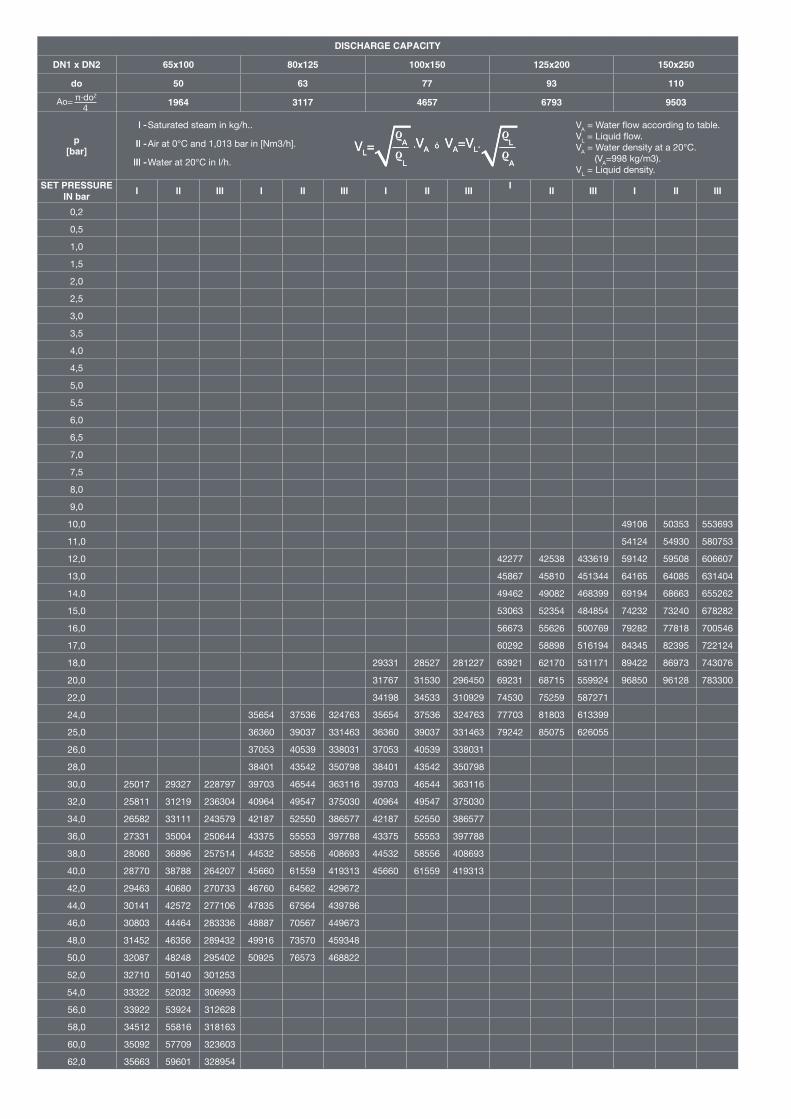
DISCHARGE CAPACITY
DN1 x DN2 65x100 80x125 100x150 125x200 150x250
do 50 63 77 93 110
1964 3117 4657 6793 9503
p[bar]
SET PRESSUREIN bar I II III I II III I II III I II III I II III
0,2
0,5
1,0
1,5
2,0
2,5
3,0
3,5
4,0
4,5
5,0
5,5
6,0
6,5
7,0
7,5
8,0
9,0
10,0 49106 50353 553693
11,0 54124 54930 580753
12,0 42277 42538 433619 59142 59508 606607
13,0 45867 45810 451344 64165 64085 631404
14,0 49462 49082 468399 69194 68663 655262
15,0 53063 52354 484854 74232 73240 678282
16,0 56673 55626 500769 79282 77818 700546
17,0 60292 58898 516194 84345 82395 722124
18,0 29331 28527 281227 63921 62170 531171 89422 86973 743076
20,0 31767 31530 296450 69231 68715 559924 96850 96128 783300
22,0 34198 34533 310929 74530 75259 587271
24,0 35654 37536 324763 35654 37536 324763 77703 81803 613399
25,0 36360 39037 331463 36360 39037 331463 79242 85075 626055
26,0 37053 40539 338031 37053 40539 338031
28,0 38401 43542 350798 38401 43542 350798
30,0 25017 29327 228797 39703 46544 363116 39703 46544 363116
32,0 25811 31219 236304 40964 49547 375030 40964 49547 375030
34,0 26582 33111 243579 42187 52550 386577 42187 52550 386577
36,0 27331 35004 250644 43375 55553 397788 43375 55553 397788
38,0 28060 36896 257514 44532 58556 408693 44532 58556 408693
40,0 28770 38788 264207 45660 61559 419313 45660 61559 419313
42,0 29463 40680 270733 46760 64562 429672
44,0 30141 42572 277106 47835 67564 439786
46,0 30803 44464 283336 48887 70567 449673
48,0 31452 46356 289432 49916 73570 459348
50,0 32087 48248 295402 50925 76573 468822
52,0 32710 50140 301253
54,0 33322 52032 306993
56,0 33922 53924 312628
58,0 34512 55816 318163
60,0 35092 57709 323603
62,0 35663 59601 328954
VA = Water flow according to table.VL = Liquid flow.VA = Water density at a 20°C.
(VA=998 kg/m3).VL = Liquid density.
I -
II -
III -
Saturated steam in kg/h..
Air at 0°C and 1,013 bar in [Nm3/h].
Water at 20°C in l/h.
I -
II -
III -

DISCHARGE CAPACITY
DN1 x DN2 200x300 250x350 300x400 400x500
do 155 180 220 280
18870 25450 38010 61575
p[bar]
SET PRESSUREIN bar I II III I II III I II III I II III
0,2 11840 13398 202775 16966 19199 302848 27484 31102 490604
0,5 14703 16748 327368 21069 23999 488930 34131 38878 792052
1,0 19414 23261 466109 27820 33332 696141 45068 53997 1127727
1,5 24087 29076 572141 34516 41665 854502 55915 67496 1384266
2,0 28730 34891 661387 41169 49998 987792 66692 80995 1600192
2,5 33349 40706 739946 47788 58331 1105121 77414 94494 1790262
3,0 37948 46521 810930 54378 66664 1211137 88091 107993 1962004
3,5 42531 52337 876182 60945 74997 1308592 98729 121492 2119878
4,0 47099 58152 936900 67492 83330 1399276 109334 134992 2266783
4,5 51656 63967 993916 74021 91663 1484430 119912 148491 2404731
5,0 56202 69782 1047834 80536 99996 1564958 130466 161990 2535183
5,5 62894 75597 1099111 90126 108329 1641540 146001 175489 2659243
6,0 69508 81413 1148099 99602 116662 1714705 161353 188988 2777768
6,5 76063 87228 1195081 108997 124995 1784874
7,0 82576 93043 1240285 118329 133328 1852386
7,5 66031 73299 951951 89056 98858 1283898 127615 141661 1917523
8,0 73572 77610 983225 99227 104673 1326077 142190 149994 1980519
9,0 83050 86234 1042964
10,0 92510 94857 1099462
11,0
12,0
13,0
14,0
15,0
16,0
17,0
18,0
20,0
22,0
24,0
25,0
26,0
28,0
30,0
32,0
34,0
36,0
38,0
40,0
42,0
44,0
46,0
48,0
50,0
52,0
54,0
56,0
58,0
60,0
62,0
VA = Water flow according to table.VL = Liquid flow.VA = Water density at a 20°C.
(VA=998 kg/m3).VL = Liquid density.
I -
II -
III -
Saturated steam in kg/h..
Air at 0°C and 1,013 bar in [Nm3/h].
Water at 20°C in l/h.

SET PRESSURES AND REGULATING RANGES
DN1 x DN2 25x32 25x40 32x50 40x65 50x80 65x100 80x125 100x150 125x200 150x250 200x300
SE
T P
RE
SS
UR
ES
IN b
ar
MAXIMUM (LIQUIDS AND GASES)
PN-160 62 62 62 62 62 62 50 40 25 20 10
MAXIMUM(SATURATED STEAM)
PN-160 62 62 62 62 62 62 50 40 25 20 10
MINIMUM
STEAMAND GASES 38 38 38 30 30 30 23 18 12 9,5 7,5
LIQUIDS 38 38 38 30 30 30 23 18 12 9,5 7,5
SP
RIN
G R
EG
UL
AT
ING
RA
NG
E
IN b
ar
7,50 to 10,00 CODE 56569
9,50 to 12,50 CODE 56566
12,00 to 16,00 CODE 56563 56567
15,00 to 20,00 CODE 56564 56568
18,00 to 25,00 CODE 56560 56565
23,00 to 32,00 CODE 56557 56561
30,00 to 40,00 CODE 56548 56551 56554 56558 56562
38,00 to 50,00 CODE56542 56544
56546 56549 56552 56555 5655956620 56622
48,00 to 62,00 CODE56543 56545
56547 56550 56553 5655656621 56623
DN1 x DN2 250x350 300x400 400x500
SE
T P
RE
SS
UR
ES
IN b
ar
MAXIMUM (LIQUIDS AND GASES) PN-160 8 7 6
MAXIMUM(SATURATED STEAM)
PN-160 8 7 6
MINIMUM
STEAMAND GASES 0,5 0,5 0,5
LIQUIDS 0,2 0,2 0,2
SP
RIN
G R
EG
UL
AT
ING
RA
NG
E
IN b
ar
0,20 to 0,68 CODE 56570 56579 56588
0,66 to 1,00 CODE 56571 56580 56589
0,95 to 1,40 CODE 56572 56581 56590
1,30 to 1,90 CODE 56573 56582 56591
1,80 to 2,60 CODE 56574 56583 56592
2,50 to 3,60 CODE 56575 56584 56593
3,50 to 5,00 CODE 56576 56585 56594
4,80 to 6,30 CODE 56577 56586 56595
6,00 to 8,00 CODE 56578 56587
Spring steel EN-10270-1-SH
Vanadium-chrome steel EN-1.8159
Stainless steel EN-1.4310
ØC
BD
A
ØL
E
SUPPORT BRACKETS DIMENSIONS
DN1xDN2 A B C D E L THICKNESS DRILLS Nº
40x65 186 96 147 70 156 14 13,5 4xM12
50x80 210 98 166 70 180 14 14 4xM12
65x100 250 100 200 70 220 14 14 4xM12
80x125 295 125 248 90 260 18 16 4xM16
100x150 344 129 292 90 309 18 17 4xM16
125x200 374 129 309 90 339 18 17 4xM16
150x250 440 184 370 120 400 18 20 4xM16
200x300 530 188 459 130 494 23 20 4xM20
250x350 664 195 581 160 624 23 20 4xM20
300x400 710 215 616 180 655 23 23 4xM20
400x500 880 238 760 200 820 23 23 4xM20
Support brackets will only be drilled if specified by the customer

Informative brochure, without obligation and subject to our General Sales Conditions.
+34 93 735 76 90 [email protected] 89034/14Avenc del Daví, 22 Pol. Ind. Can Petit 08227 TERRASSA (Barcelona) SPAINwww.vycindustrial.com
COEFFICIENT OF DISCHARGE
DN1x DN2 25x32 25x40 32x50 40x65 50x80 65x100 80x125 100x150 125x200 150x250 200x300 250x350 300x400 400x500
do 16 20 25 32 40 50 63 77 93 110 155 180 220 280
h 7,00 9,00 12,00 12,00 18,00 18,00 20,00 29,00 34,40 36,80 56,15 64,80 79,20 100,80
h1 2,60 3,20 4,00 5,20 6,50 8,00 10,00 12,50 16,74 19,80 27,90 32,4 39,6 50,4
h/do0,44 0,45 0,48 0,38 0,45 0,36 0,32 0,38 0,37 0,33 0,36 0,36 0,36 0,36
h1/do (1)0,16 0,16 0,16 0,16 0,16 0,16 0,16 0,16 0,18 0,18 0,18 0,18 0,18 0,18
CO
EFF
ICIE
NT
OF
DIS
CH
AR
GE
kd
SATURATED STEAMGASES
0,78 0,74 0,71
LIQUIDS 0,60 0,52 ─
LIQUIDS WITHRAPID LIMITER
(1)0,36 ─
Overpressure factors Multiply the discharge capacity ob-tained from the tables, by the cor-rection factor, in order to obtain the discharge capacity at required over-pressure.
AirSaturated steam
Water
1,28
1,26
1,24
1,22
1,20
1,18
1,16
1,14
1,12
1,10
1,08
1,06
1,04
1,02
1,005 10 15 20 25
% p
Liquids
(1) d0 16-63(2) d0 77(3) d0 93-155
Saturated steamGases
(1) d0 16-77(2) d0 93-110(3) d0 155-180(4) d0 220-280
(1) d0 16-110(2) d0 155-180(3) d0 220-280
Saturated steamGases
Founded in 1914