Embed Size (px)
Citation preview

Model 428
Color ReflectionDensitometer
Operation Manual

ii
Dear Customer:
Congratulations! We at X-Rite, Incorporated are proud to presentyou with the X-Rite 418 Color Reflection Densitometer. Thisinstrument represents the very latest in microcontrollers, integratedcircuits, optics, and display technology. Your X-Rite 418 is arugged, reliable, finely engineered instrument whose performance isunsurpassed.
To fully appreciate and protect your investment, we suggest that youtake the necessary time to read and fully understand this manual. Asalways, X-Rite stands behind your 418 with a full one year limitedwarranty and a dedicated service organization. If the need arises,please don’t hesitate to call us.
Thank you for your trust and confidence.
X-Rite, Incorporated

iiiiii
FEDERAL COMMUNICATIONS COMMISSION NOTICE
FCC StatementThis equipment has been tested and found to comply with the limitsfor a Class A digital device, pursuant to Part 15 of the FCC Rules.These limits are designed to provide reasonable protection againstharmful interference when the equipment is operated in acommercial environment. This equipment generates, uses, and canradiate radio frequency energy and, if not installed and used inaccordance with the instruction manual, may cause harmfulinterference to radio communications. Operation of this equipmentin a residential area is likely to cause harmful interference in whichcase the user will be required to correct the interference at his ownexpense.
CanadaThis Class A digital apparatus meets all requirements of theCanadian Interference-Causing Equipment Regulations.
Cet appareil numérique de la classe A respecte toutes les exigencesdu Règlement sur le matériel brouilleur du Canada.
The Manufacturer: X-Rite, IncorporatedDer Hersteller: 3100 44th Street, S.W.El fabricante: Grandville, Michigan 49418Le fabricant:Il fabbricante:
Declares that: Densitometergibt bekannt: 428advierte que:avertit que:avverte che:
is not intended to be connected to a public telecommunicationsnetwork.an ein öffentliches Telekommunikations-Netzwerk nichtangeschlossen werden soll.no debe ser conectado a redes de telecomunicaciones públicas.ne doit pas être relié à un réseau de télécommunications publique.non deve essere connettuto a reti di telecomunicazioni pubblici.

iviv
CAUTION: Operational hazard exists if AC adaptor other than X-Rite SE30-61 (115V) or SE30-62 (230V) is used.
VORSICHT: Es besteht Betriebsgefahr bei der Verwendung voneinem Adapter außer X-Rite SE30-61 (115 U) oder SE30-62 (230U).
AVISO: No use otro adaptador C.A. que no sea la pieza X-RiteSE30-61 (115V) o SE30-62 (230V), por el riesgo de malfuncionamiento del equipo.
ATTENTION: Ne pas utiliser d’adaptateur autre que SE30-61(115V) ou SE30-62 (230V) de X-Rite au risque de mauvaisfonctionnement de l’appareil.
AVVISO: Non usare un altro adattatore C.A. che non è del pezzoX-Rite SE30-61 (115V) o SE30-62 (230V), per il rischio dimalfunzionamento dell’apparecchio.
NOTE: Shielded interface cables must be used in order tomaintain compliance with the desired FCC and European emissionrequirements.

vv
WARNING: This instrument is not for use in explosiveenvironment.
WARNUNG: Das Gerät soll in einer explosiven Umgebung NICHTverwendet werden.
ADVERTENCIA: NO use este aparato en los ambientes explosivos.
ATTENTION: Cet instrument NE DOIT PAS être utilisé dans unenvironnement explosif.
AVVERTIMENTO: NON usare questo apparecchio in ambientiesplosivi.
USE ONLY: AA NICad batteries that are 600/700mAhr rated, sixrequired. Other types may burst causing personal injury.
AUFGEPASST: Verwenden Sie nur AA Nicad Akkus von600/700mAhr (Milliampere/Stunde) Nennstrom (6 Stückerforderlich). Mit anderen Akkus läuft die Gefahr von Explosionund Verletzung.
ATENCION: Use solamente las pilas de AA NiCad (se requiereseis) con condiciones de funcionamiento normales 600/700mAhr(horas miliamperios). Es posible que los otros tipos puedan estallar ycausar daños corporales.
ATTENTION: Utiliser seulement les batteries NICad à courantnominal de 600mAh (milliampère/heure) (6 pièces nécessaire). Il ya danger d'explosion et de blessures avec les autres types.
ATTENZIONE: Usare solamente gli accumulatori al AA NiCad (sirichiede sei) con le condizioni di funzionamento normali600/700mAhr (ore milliamperi). E possibile che altri tipi possanoscoppiare e causare danno personale.

vivi
Contents
1 Overview and SetupFeatures............................................................................ 1-1Packaging and Parts.......................................................... 1-3Instrument Vocabulary....................................................... 1-4Unlocking/Locking the Shoe .............................................. 1-5Batteries and Power .......................................................... 1-6Adjusting the Display Angle ............................................... 1-9I/O Port Setup ................................................................. 1-10Tolerance ........................................................................ 1-15X10 Setup ....................................................................... 1-18
2 CalibrationResponse Settings............................................................. 2-2Overview of Calibration Procedures .................................. 2-4Long Calibration ................................................................ 2-4Color Correlation (CC) Calibration ..................................... 2-8Quick-Cal™..................................................................... 2-10
3 Electronic Function SelectionEFS Measurement............................................................. 3-2NEFS Measurement .......................................................... 3-3
4 Density FunctionsSelecting Density Function ................................................ 4-2Selecting Density Mode..................................................... 4-3Selecting Color Measurement Method ............................... 4-5Density Measurement........................................................ 4-6Density Difference Measurement....................................... 4-8
5 Dot FunctionsSelecting Dot Area or Dot Gain.......................................... 5-2Selecting Color Measurement Method ............................... 5-3Dot Area Function ............................................................. 5-4Dot Gain Function ............................................................. 5-5

viivii
6 Trap FunctionsTrap Formulas................................................................... 6-1Selecting Trap Function..................................................... 6-3Trap Measurement ............................................................ 6-5Trap Difference Measurement ........................................... 6-8Trap DMAX Entry ............................................................ 6-10
7 Print Contrast FunctionsSelecting Print Contrast Function ...................................... 7-2Selecting Print Contrast Mode ........................................... 7-3Selecting Color Measurement Method ............................... 7-5Print Contrast Measurement .............................................. 7-6Print Contrast Difference Measurement............................. 7-8
8 Hue Error & Grayness FunctionsFormulas ........................................................................... 8-1Selecting Hue Error/Grayness Function ............................. 8-2Selecting Hue Error/Grayness Mode.................................. 8-3Hue Error/Grayness Measurement..................................... 8-5Hue Error/Grayness Difference Measurement ................... 8-6
9 Hue Error & Saturation FunctionsFormulas ........................................................................... 9-1Selecting Hue Error/Saturation Functions .......................... 9-2Selecting Hue Error/Saturation Mode................................. 9-3Hue Error/Saturation Measurement ................................... 9-5Hue Error/Saturation Difference Measurement .................. 9-6
10 Cast/Brightness & Reflectance FunctionsFormulas ......................................................................... 10-1Selecting Cast/Brightness or Reflectance Functions ........ 10-2Cast/Brightness or Reflectance Measurement ................. 10-3Cast/Brightness Difference Measurement........................ 10-3
11 StatisticsFormulas ......................................................................... 11-1Mean............................................................................... 11-2Sigma.............................................................................. 11-2Range ............................................................................. 11-3

viiiviii
12 Technical InformationSerial Interface Information ............................................. 12-1Instrument Specifications ................................................ 12-4Accessories ..................................................................... 12-7General Cleaning ............................................................ 12-8Optics Maintenance......................................................... 12-8Target Window Replacement .......................................... 12-9Lamp Replacement ........................................................ 12-10
13 Appendices and IndexDisplay Messages............................................................ 13-1Proprietary Notice............................................................ 13-3Limited Warranty............................................................. 13-4Index ............................................................................... 13-5
Copyright 1987, 1999 byX-Rite, Incorporated“ALL RIGHTS RESERVED”
X-Rite is a registered trademark and Quick Cal™, Q Cal™, Electronic Function
Selection™, Computerized Color Response™, and CCR™, are trademarks of X-Rite,
Incorporated. All other logos, brand names, and product names are the properties of their
respective holders.

1-11-1
D
1 Overviewand Setup
Features ................................... 1-1Packaging and Parts.................... 1-3Instrument Vocabulary .............. 1-4Unlocking/Locking the Shoe...... 1-5Batteries and Power.................. 1-6Adjusting the Display Angle....... 1-9I/O Port Setup......................... 1-10Tolerance................................ 1-15x10 Setup ............................... 1-18
The X-Rite 428 Color Reflection Densitometer is designed to meetthe quality control needs of today’s pressroom and graphic artstechnicians. This completely portable instrument features differentmeasurement modes for quickly measuring ink density, densitydifference, dot area, dot gain, trap, print contrast, hue error,grayness, saturation, cast, brightness, and reflectance.Measurements are taken with simple hand-held operation, andmeasurement data is clearly read on the interactive display. Thethree control buttons make measurement mode selection easy.
FEATURES
The X-Rite 428 features several state-of-the-art technologies thatplace the instrument a step above competitive instruments in termsof accuracy, speed, and simplicity:
Computerized Color Response™ (CCR)The versatile 428 accommodates multiple status responses. Model428G can take measurements using ANSI-Status T response, whichis compatible with the GCA T-reference (T-Ref) standard. You canalso select the traditional X-Rite graphic arts response, Status G.Model 428E features European Status E and Status I (displayed asN—for Narrow Band Glass Interference Type) responses.

428 Color Reflection Densitometer
1-21-2
QuickCal™ One-Step CalibrationThe 428’s Quick-Cal feature makes calibration fast and easy. Yousimply select the “Q-Cal” mode on the instrument, then measure thewhite patch on the supplied calibration target card. You can also getcomplete agreement with other densitometers using the three-colorresponse calibration.
Automatic On/Shut-OffTo increase battery life, the 428 automatically turns itself off if it hasnot been used within 45 seconds; and it automatically turns backwhenever a key is pressed or measurement taken. Tests have shownthat over 4,500 readings can be taken on one charge of newbatteries.
Nonvolatile MemoryA lithium battery stores calibration data and measured values whenthe densitometer’s primary rechargeable batteries are depleted orremoved.
Automatic Color SelectionEquipped with Auto Color Select, the 428 eliminates manualrotation of a filter wheel and related erroneous measurements. Allcolors are measured simultaneously, then the correct reading isdisplayed in less than one second.
Additional Features• Large LCD display clearly identifies measurement data and
mode function. No need for numeric codes to identify thisinformation.
• Three large buttons place all function controls at operator’sfingertips.
• Small 1.7mm aperture (GS or ES model) for reading reduced-size color bar patches.
• AC adapter is provided to allow readings while batteries arebeing recharged.
• Replaceable optics allow you to switch between “G” and “E”response.
• Two-way RS-232 interface operates at 1200 baud, or one ofseveral other baud rates.

Overview and Setup
1-31-3
PACKAGING AND PARTS
After removing the instrument from the shipping carton, inspect forpossible damage. If any damage is noted, contact the transportationcompany immediately. Do nothing more until the carrier’s agent hasinspected the damage.
If damage is not evident, check to ensure that all items are included(refer to the parts list below).
Your Package Should Include…1 428 Color Reflection Densitometer1 Carrying Case1 Operation Manual1 Color Reflection Calibration Reference;
either 418-62 for Model 428 or 418/LP-62 for Model 428/LP1 Warranty Registration Card1 P/N SE30-61 Battery Charger, 115V
or P/N SE30-62 Battery Charger, 230V1 P/N SD01-41 Certificate of Calibration
Along with this Operation Manual, several important notices areincluded. You should read each of these notices before using theinstrument.
Return PackagingYour X-Rite 428 was packaged in a carton specially designed toprevent damage. If re-shipment is necessary, the instrument shouldbe re-packaged in the original carton. If the original carton is notavailable, a new one can be obtained from X-Rite.

428 Color Reflection Densitometer
1-41-4
INSTRUMENT VOCABULARY
FUNCTION COLOR ZERO
CAL
16-characterInteractive Display
3 Operating Keys
AC Adapter(Charger) Jack
RS232I/O Port
Target Window
Shoe
FUNCTION (▼)Button
COLOR (▲) Button
ZERO (▼▲)Button
Arrows indicate button’s function foradjusting display values up or down.

Overview and Setup
1-51-5
UNLOCKING/LOCKING THE SHOE
To take measurements with the instrument, you must unlock theShoe (see Instrument Vocabulary drawing on previous page). Whenthe instrument is not in use, the Shoe should be re-locked to protectthe instrument optics.
A sliding button on the bottom of the instrument locks the Shoeclosed.
To unlock, hold Shoe against the unit and slide the lock button backuntil the button latch clears the Shoe tab. Carefully release the Shoeto open. (Figure 1-1)
To lock, hold the Shoe against the unit and slide the lock buttonforward until the button latch captures the Shoe tab. (Figure 1-2)
Figure 1-1 Figure 1-2
Button Latch
Shoe Tab
Latchcaptures Tab

428 Color Reflection Densitometer
1-61-6
BATTERIES AND POWER
Your 428 instrument’s batteries should be charged before use. It canbe operated while the batteries are being charged.
Before you begin charging, you must remove the battery isolationinsert protruding from the battery cover. (Figure 1-3)
Figure 1-3
NOTE: Make sure the voltage indicated on the AC adaptercomplies with the AC line voltage in your area. If it does not,contact yourX-Rite dealer.
To charge the battery:
1. Plug the AC Adapter Line Cord into the AC Adapter Jack onback of instrument. (Figure 1-4)
2. Plug AC Adapter into AC wall outlet.
You can use the instrument while it recharges. The instrumentwill be fully charged in approximately 14 hours.
Battery Isolation Tab

Overview and Setup
1-71-7
Figure 1-4
NOTE: If your unit has not been used for several weeks recharge forapproximately 24 hours.
NOTE: When storing the unit for a long period of time, thebatteries should be removed.
Applying PowerThe instrument remains “powered down” until a measurement istaken. When a measurement is taken, or when any key is pressed,the instrument automatically turns on.
If no measurements are taken or keys pressed for 45 seconds, theinstrument automatically turns off again to conserve battery power.
Plug AC Adapter Cordinto ACAdapter Jack

428 Color Reflection Densitometer
1-81-8
Inserting/Removing the BatteriesYour instrument is shipped with six AA NICAD batteries alreadyinstalled. Should you ever need to replace the batteries, first closeand lock the Shoe (when the shoe is unlocked and open, it blocksthe battery door). Next, slide the battery door in the rear of theinstrument down and off. The batteries will spring out a bit.
To replace the batteries, insert six fresh AA NICAD batteries intothe instrument, three into each chamber. Note the proper polarityof the batteries in Figure 1-5, and on the CAUTION labelbeneath the instrument. You will need to press and hold thebatteries down in place while you slide the battery cover back on.Push the cover into place until it is flush with the bottom of theinstrument.
Figure 1-5

Overview and Setup
1-91-9
ADJUSTING THE DISPLAY ANGLE
You can most clearly read the LCD display by viewing it at a 90°angle. The angle of the display can be adjusted to accommodate thisfor different user sight lines.
To adjust the display angle:
1. Set the Display Angle Adjustment Knob on the right side of theinstrument to its midpoint setting. (Figure 1-6)
Figure 1-6
2. Activate the display by taking a measurement or pressing acontrol button.
3. Adjust the Display Angle Adjustment Knob until the displayeddata can be most clearly seen from your line of sight.
Display AngleAdjustment Knob

428 Color Reflection Densitometer
1-101-10
I/O PORT SETUP
Your X-Rite 428 has a serial port that allows data to be transmittedtoor received from an external device. With this I/O connectionmade, the 428 can be controlled externally by Serial InputCommands.
If you do not plan to use the I/O port at this time, you can skipahead to Chapter 2, “Calibration.”
You can configure different functions of your I/O port using theinstrument’s MODE selection procedures. You can set up:
• The desired Baud rate (output rate of characters per second) fortransmitting data via the I/O port;
• the desired header (HDR) that will appear above the transmittedor printed data; and
• the desired computer output format (COMP).
To set up the I/O port:
1. Press the FUNCTION button and the COLOR buttonsimultaneously, then release.
NO cal T YES appears in the display, where “T” representsStatus response (T, G, E, or N).
2. Press FUNCTION to indicate no, you do not want to calibrate.NO modes YES appears in the display.
3. Press ZERO to indicate yes, you do want to set mode.↓ RESPONSE T appears in the display.
4. Press FUNCTION four times to advance the mode selectionuntil ← I/O RS-232 YES appears.
NO calT YES
NO modes YES
^ RESPONSE T
<I/O RS-232 YES

Overview and Setup
1-111-11
5. Press ZERO; each depression of the ZERO key will toggle RCION or RCI OFF in the screen. This enables or disables theability to externally control the 428 via the I/O port.
6. Press FUNCTION; each depression of the ZERO key willtoggle REF PRINT ON and REF PRINT OFF. This enables ordisables the reference values during printout.
7. Press FUNCTION; each depression of the ZERO key willtoggle between PIN 5 BUSY, CTS, and OFF. This determinesthe status of Pin 5 of the I/O port—off, busy, or clear to send(CTS). Pin 5 should normally be set to off when Pin 5 is notgoing to be used.
8. Press FUNCTION; BAUD plus a baud rate settingappearseither OFF, 300, 600, 1200, 2400, 4800, or 9600.Press ZERO again to toggle to the next baud rate setting. Pressrepeatedly to toggle through all selections.
9. When the desired baud rate setting appears, press FUNCTIONto select the setting. HDR ON or HDR OFF appears in thedisplay.
10. Press ZERO to toggle to the desired setting, either PRINT HDRON or PRINT HDR OFF.
When PRINT HDR ON is selected, a header will appearabove transmitted or printed data indicating the data typeforexample, DEN for density.—When PRINT HDR OFF is selected, no header appears.
EXAMPLE: Header On EXAMPLE: Header Off
^ BAUD 1200
^ PRINT HDR ON
DENC 1.24 C 1.24
^ RCI OFF
^ REF PRINT ON
^ PIN 5 OFF

428 Color Reflection Densitometer
1-121-12
11. Press FUNCTION; each depression of the ZERO key willtoggle between DEC POINT OFF and DEC POINT ON. Thisdetermines the status of the decimal point during printout.
12. Press FUNCTION; each depression of the ZERO key willtoggle between CR only and CR and LF. This determines thedelimiter at the end of each line of data during printout—acarriage return or a carriage return with a line feed.
13. When the desired setting appears in the display, pressFUNCTION to select the setting. COMP ON or COMP OFFappears in the display.
14. Press ZERO to toggle to the desired setting, either COMP ONor COMP OFF.
When COMP ON is selected, transmitted or printed data willsimply be configured with single spaces between eachmeasurement value.When COMP OFF is selected, transmitted or printed datawill be configured in a “column” format, with a carriage returnand line feed after each measurement value.
EXAMPLE: COMP On
EXAMPLE: COMP Off
^ COMP ON
DEN V0.67 C0.20 M1.23 Y0.77
DENV0.67C0.20M1.23Y0.77
^ DEC.POINT ON
^ CR only

Overview and Setup
1-131-13
15. Press FUNCTION; each depression of the ZERO key willtoggle between XON/XOFF ON and XON/XOFF OFF. This isfor handshaking via data transmission, and is a bi-directionalhandshaking protocol.
When the mode is set to on (ASCII=11H) communication isenabled.When the mode is set to off (ASCII=13H) communication isdisabled. When the mode is set to XON/XOFF OFF, protocol isnot used.
16. When the desired setting appears in the display, pressFUNCTION twice to select the setting and return to normaloperation.
< XON/XOFF OFF

428 Color Reflection Densitometer
1-141-14
RS232 Connector InterfaceYour X-Rite 428 instrument can be connected to a computer orprinter using a standard RS232 9-pin connector.
For more information on Serial Input Commands and remotecontrol operation of the 428 order the Serial Interface Manual, P/N428-506, from X-Rite, Incorporated.
I/O Port for Serial Interface

Overview and Setup
1-151-15
TOLERANCE
Tolerance values for reference settings can be preset in the 428. Thisallows at-a-glance verification if your measurement is in tolerance toyour reference. An out of tolerance condition will be displayed forevery function (except reflectance) when measurement exceeds thereference value + or – the tolerance value.
Tolerance can be completely turned off, or each individual functioncan have its tolerance shut off by setting the tolerance or referencevalue to zero. Tolerance settings can range from 0.00 to 0.59 (or 0%to 59%).
During operation, tolerance values are displayed as follows:Under tolerance vX.XXOver tolerance ^X.XX
Tolerance Settings• With EFS on, DEN allows a tolerance setting for v, c, m, y, and
3 color. With NEFS on, DEN allows a tolerance setting for v, c,m, y, r, b, g, and 3 color.
• Dot gain allows a gain setting for each reference (1, 2, 3) andeach color (v, c, m, y).
• Dot tolerance allows a tolerance setting for each dot gainreference (1, 2, 3) and each color (v, c, m, y).
• Trap allows a tolerance setting for 16 different color-over-colorcombinations.
• Print contrast allows a tolerance setting for v, c, m, and y.• Hue error/grayness or saturation allow a tolerance setting for six
different color combinations.• Cast/ brightness allows a tolerance setting for cast and
brightness.
Tolerance Setup ProcedureBefore measurement or calculation, set your desired tolerancevalues.
1. Press FUNCTION and COLOR simultaneously and release.NO calT YES will display (where T is the selected response).
2. Press FUNCTION to indicate no, you do not want to calibrate.
NO cal T YES
NO modes YES
428 Color Reflection Densitometer
1-161-16
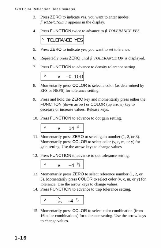
3. Press ZERO to indicate yes, you want to enter modes.↓ RESPONSE T appears in the display.
4. Press FUNCTION twice to advance to ↓ TOLERANCE YES.
5. Press ZERO to indicate yes, you want to set tolerance.
6. Repeatedly press ZERO until ↓ TOLERANCE ON is displayed.
7. Press FUNCTION to advance to density tolerance setting.
8. Momentarily press COLOR to select a color (as determined byEFS or NEFS) for tolerance setting.
9. Press and hold the ZERO key and momentarily press either theFUNCTION (down arrow) or COLOR (up arrow) key todecrease or increase values. Release keys.
10. Press FUNCTION to advance to dot gain setting.
11. Momentarily press ZERO to select gain number (1, 2, or 3).Momentarily press COLOR to select color (v, c, m, or y) forgain setting. Use the arrow keys to change values.
12. Press FUNCTION to advance to dot tolerance setting.
13. Momentarily press ZERO to select reference number (1, 2, or3). Momentarily press COLOR to select color (v, c, m, or y) fortolerance. Use the arrow keys to change values.
14. Press FUNCTION to advance to trap tolerance setting.
15. Momentarily press COLOR to select color combination (from16 color combinations) for tolerance setting. Use the arrow keysto change values.
^ TOLERANCE YES
^ v ±0.10D
^ v 14 GI
^ v ±4 %3
^ ±4 Tnvm

Overview and Setup
1-171-17
16. Press FUNCTION to advance print contrast tolerance setting.
17. Momentarily press COLOR to select color (v, c, m, or y) fortolerance setting. Use the arrow keys to change values.
18. Press FUNCTION to advance to hue error/grayness or hue errorsaturation tolerance setting (depending on your settings).
19. Momentarily press ZERO to select H or G (or S)--the cursorbelow the letter indicates which is active. Momentarily pressCOLOR to select color combination (6 color combinations) fortolerance setting. Use the arrow keys to change values.
20. Press FUNCTION to advance to cast/brightness tolerancesetting.
21. Momentarily press ZERO to select C or B (the cursor below theletter indicates which is active). Use the arrow keys to changevalues.
22. Press FUNCTION four times to return to normal operation.
NOTE: All tolerances are factory preset to ±0.10D for densities,±14% for dot gain reference 1 and 3, ±22% for dot gain reference 2,and ±4% for all others.
^ v ±4 Pc
^ ±4 H ±0.01Srm
±4C ±4B

428 Color Reflection Densitometer
1-181-18
X10 SETUP
When activated, the x10 function allows an extra digit to bedisplayed to the right of the decimal point when extreme resolutionis required.
x10 On/Off Procedure1. Press FUNCTION and COLOR simultaneously, then release.
NO CalT YES will display (where T is the selected response).
2. Press FUNCTION to indicate no, you do not want to calibrate.
3. Press ZERO to indicate yes, you want to enter modes.
4. Press FUNCTION three times to advance to x10 selection.
5. Each momentary depression of ZERO will alternate betweenX10 ON and X10 OFF.
6. When your preference is displayed, press FUNCTION twice toreturn to normal operation.
NO calT YES
NO modes YES
^ X10 OFF

2-12-1
2 Calibration
Response Settings .................... 2-2Overview of CalibrationProcedures ............................... 2-4Long Calibration........................ 2-4Color Correlation (CC)Calibration ................................ 2-8Quick-Cal™ ............................2-10
Frequency of CalibrationUnder long operating conditions, the instrument should becalibrated once per week, or whenever the instrument displays amessage regarding calibration. You should perform a “longcalibration” whenever possible. However, you can also perform aQuick-Cal™ procedure any time after an initial long calibration hasbeen performed.
Before calibrating, you should determine the appropriatedensitometer response setting for your instrument, based on yourproduction control requirements.

428 Color Reflection Densitometer
2-22-2
RESPONSE SETTINGS
A densitometer’s measurement system consists of several differentcomponents (lamp, optics, light sensor). Different densitometersconsist of different types of these components. The density readingsmeasured by these systems are called a densitometer response.Because components differ among densitometers, standardresponses have been established in the industry. These standardsensure that even instruments with different components willmeasure in accordance with the same response.
With the complete set of opticsfor version 428G and 428Eyourversatile 428 instrument allows you to utilize four differentdensitometer response settings.
Descriptions of Available ResponsesUsing 428G optics, your 428 instrument can use the followingresponses:
• Status TANSI Status T Computerized Color Response iswideband response most typically used in the North Americangraphic arts industry. This status is used to calibrate theinstrument to the T-Ref™ color reference.
• Status GX-Rite Graphic Arts Response is a widebandresponse that is similar to Status T, except that it is moresensitive to denser yellow inks.
Using 428E optics, your 428 instrument can use the followingresponses:
• Status EEuropean utilizes the Wratten 47B filter—forhigher readings in yellowinstead of the Wratten 47 filtertypically used in North America.
• Status I (displayed as Status N)Narrow Band GlassInterference Type Computerized Color response is computercorrected and designed for use with process inks on paper.Measurements other than process inks may producemeasurement data with slight discrepancies. NOTE: The 428displays this Status as Status N.

Calibration
2-32-3
Selecting ResponseTo select the appropriate response:
1. First, if this is your first time selecting response, you shouldplug your instrument in using its AC adapter. This will preventthe microprocessor from going into “sleep” mode to save batterypower. With the instrument plugged in, you’ll be free to takeyour time learning this procedure.
2. Press the FUNCTION button and the COLOR buttonsimultaneously, then release. NO cal T YES appears in thedisplay, where “T” represents Status T response. Theinstrument is preset to “T” at the factory.
3. Press FUNCTION to indicate no, you do not want to calibrate.N modes Y appears.
4. Press ZERO to indicate yes, you want to enter modes.↓ RESPONSE T appears.
5. Press ZERO again to toggle the Status selection between T andG (for 428G), or E and N (for 428E). Stop when the desiredresponse is displayed.
6. Press FUNCTION five times to return to the main display.
NOTE: Separate memory positions store calibration data foreach of the four responses. If you change optics or changeresponse setting, you must re-calibrate using that response.
You do not need to re-calibrate when you switch to a responsefor which you have already calibrated.
NO calT YES
^ RESPONSE T
NO modes YES

428 Color Reflection Densitometer
2-42-4
OVERVIEW OF CALIBRATION PROCEDURES
Calibrating your instrument is crucial to maintaining itsmeasurement stability. It is also important to maintainingmeasurement agreement between several densitometers at the samesite; and making all densitometers calibrate precisely to the samestandard reference, such as T-Ref. Your 428 instrument’sComputerized Color Response™ allows you to use one of threedifferent calibration procedures to address these factors:
1. Long Calibration allows you to calibrate your instrument toany color reference. This procedure will be used before you takeyour first measurements for each response. After this calibrationprocedure has been performed, you can use Quick-Cal™ (seebelow) to quickly re-calibrate when necessary.
2. Color Correlation Calibration allows you to set the 428 tomeasure in agreement with another densitometer that has thesame response (for example, two wideband densitometers).
3. Quick Cal™ allows you to quickly re-calibrate to white withouthaving to re-measure the black and/or color patches.
LONG CALIBRATION
1. If this is your first time calibrating, you should plug yourinstrument in using its AC adapter. This will prevent themicroprocessor from going into “sleep” mode to save batterypower. With the instrument plugged in, you’ll be free to takeyour time learning this procedure.
2. Unlock the Shoe.
3. Press the FUNCTION and COLOR buttons simultaneouslyuntil NO cal T YES appears in the display. T stands for thedefault Status T Response; if you have a different responseselected, its initial letter will appear in this position. (See“Selecting Response” earlier in this chapter.)
4. Press ZERO to indicate Yes, you do want to calibrate.
NO calT YES
NO Quickcal YES

Calibration
2-52-5
5. Press FUNCTION to select long calibration. SET LOWVALUES appears in the display fora moment.
6. At this point, refer to the front ofyour Color Reflection ReferenceEnvelope. (Figure 2-1)
The first value that appears in thedisplay should match the visual(“V”) value for the T Responseprinted on your envelope under:
STEP 1 (WHITE) CAL-LO
T V0.07 C0.06 M0.07 Y0.10G V0.07 C0.06 M0.07 Y0.10
NOTE: Values shown above andin Figure 2-1 are examplesyourvalues may be different.
7. If the values on the envelope and on the display do not match,enter the correct value using the blue and red arrow buttons.
To lower the value:Press and hold the ZERO (▼▲) button, then pressFUNCTION (▼) repeatedly to lower the value until the correctvalue is shown.
To raise the value:Press and hold the ZERO (▼▲) button, then press COLOR(▲) repeatedly to raise the value until the correct value isshown.
TIP: If you need to move the value up or down by a largeamount, hold the (▼▲) button and (▼) or (▲) button down.The numbers will advance faster as you hold it down.
Figure 2-1
SET LOW VALUES
v 0.07L

428 Color Reflection Densitometer
2-62-6
8. Release all buttons, then press COLOR. The T Response valuefor cyan (C) appears. It should match the value printed on yourReference Envelope.
STEP 1 (WHITE) CAL-LO
T V0.07 C0.06 M0.07 Y0.10G V0.07 C0.06 M0.07 Y0.10
9. If the values on the envelope and on the display do not match,use the blue and red arrow buttons as specified in #7 to enter thecorrect value.
10. Follow #8 again for magenta (M), and then again for yellow(Y).If the envelope and display values do not match for either color,follow #7 to correct.
11. Press COLOR again. SET HIGH VALUES appears for amoment. Then, the Step 3 (Black) CAL-HI value for the TResponse appears. (Figure 2-1)
12. If the values on the envelope and on the display do not match,use the blue and red arrow buttons as specified in #7 to enter thecorrect value.
13. Repeat #11 for Step 4 (cyan), Step 5 (magenta), and Step 6(yellow). Follow #7 if you need to correct the values. (Figure 2-1)
14. Press COLOR again. READ WHITE appears.
15. Take your Color Reflection Card out of the envelope. Lay it on aflat, steady surface with the color target side facing up (seeFigure 2-2).
READ WHITE
SET HIGH VALUES T v 1.92H

Calibration
2-72-7
Figure 2-2
16. Read Step 1the white target patchby placing the instrumenttarget window cross-hairs over the alignment marks, thenlowering the head down onto the shoe. One of the filter valuesfor Step 1 appears in the display, then READ BLACK appears.
17. Read Step 3the black target patch (not Step 2, the graypatch). One of the filter values for Step 3 appears in the display,then READ CYAN appears.
18. Repeat these measurement steps for Step 4 (cyan), Step 5(magenta), and Step 6 (yellow).
The values that appear for each Step measurement shouldmatch the values listed on the envelope for that Step. If they donot, repeat the calibration procedure. If discrepancies continueto exist, contact X-Rite Instrument Services.
If all values were correct, your instrument is calibrated!
If you wish to calibrate to make your instrument measure inagreement with another instrument, perform the followingprocedures for “Color Correlation Calibration.”
Color TargetPatches
Alignmentmarks
v 0.06L READ BLACK

428 Color Reflection Densitometer
2-82-8
COLOR CORRELATION (CC) CALIBRATION
There are two ways to perform color correlation calibration, whichcreates measurement agreement between your 428 and another,similar instrument. The method you use depends on the type ofcalibration reference used by the other instrument.
NOTE: Color correlation between two instruments can best beachieved between two very similar instrumentstwo that utilize thesame Status setting, have the same optics type, aperture size, andpolarization (both haveor both do not havepolarization filters).
If the other instrument uses a reference similar to the 428’swithblack, white, cyan, magenta, and yellow ink targets on paperthenuse the first set of instructions. If the other instrument uses areference without CMYK patchessuch as a ceramic plaque withwhite and black onlythen use the second set of instructions.
CC Using Master Instrument CMYK Target1. Calibrate the other, “master” instrument according to its
manufacturer’s specifications and instructions.
2. Begin a long calibration procedure for your 428 instrument (seeprevious section).
3. When verifying the calibration values on the calibrationreference envelope, use the values for the master instrument’scalibration standard instead. Use the procedure in #7 of thelong calibration instructions to modify the values on yourinstrument display to match those on the master instrument’senvelope or reference.
4. When calibration is due for either instrument, use the masterinstrument’s calibration reference.

Calibration
2-92-9
CC with No Master Instrument CMYK Target1. Get a pen or pencil and piece of paper ready.
2. Calibrate the master instrument according to its manufacturer’sspecifications and instructions.
3. Prepare the master instrument to read low density (whiteCAL LO).
4. Measure Step 1 (white) on the 428’s calibration reference usingthe master instrument. Write down the low density values forvisual, cyan, magenta, and yellow.
5. Prepare the master instrument to read high density (blackCAL HI).
6. Measure Step 3 (black) on the 428’s calibration reference usingthe master instrument. Write down the high density values forvisual, cyan, magenta, and yellow.
7. Prepare the master instrument to read color patches.
8. Read Steps 4, 5, and 6 (cyan, magenta, and yellow) on the 428’scalibration reference using the master instrument. Write downthe density values for each color.
9. Begin a long calibration using your 428 instrument. Whensetting the CAL LO values, verify the visual, cyan, magenta,and yellow values against the low density values you measuredwith the master instrument. Use the arrow buttons to adjust thevalues (see #7 of the last section).
10. Press COLOR again to advance to setting the CAL HI values.Verify the visual, cyan, magenta, and yellow values against thehigh density values you measured with the master instrument.Use the arrow buttons to adjust the values (see #7 of the lastsection).
11. When you enter the last CAL HI value, the instrumentrecognizes that you have entered measured black values foreach color filter. NO cal color YES appears in the display,asking if you wish to perform a color correlation calibration.
12. Press COLOR to indicate yes, you do want to perform a colorcorrelation calibration.

428 Color Reflection Densitometer
2-102-10
13. SET cmy appears briefly in the display, followed by the CAL-HIvalue for cyan. Verify the cyan value against the cyan value youmeasured with the master instrument. Use the arrow buttons toadjust the value (see #7 of the last section).
14. Verify the magenta and yellow values against the valuesmeasured with the master instrument, then adjust the values tomatch the master values as necessary.
15. READ WHT appears in the display. Measure white, then verifythat the value matches the values recorded for each masterinstrument measurement. The display prompts you to measureSteps 3, 4, 5, and 6. Verify that these values match the masterinstrument’s measurements, as well.
16. Perform future calibrations of your 428 using this procedure.
QUICK CAL™Once you have performed the long calibration, you can simplyperform the Quick Cal™ procedure periodically to set the lowdensity (white) value.
NOTE: In most cases, you should simply perform an entire longcalibration if possible.
1. Press FUNCTION and COLOR simultaneously, then release.NO cal T YES appears in the display. T stands for the defaultStatus T Response; if you have a different response selected, itsinitial letter will appear in this position. (See “SelectingResponse” earlier in this chapter.)
2. Press ZERO to indicate yes, you do want to calibrate.
3. Press ZERO to select Quick Cal™ procedure.
4. The screen will display READ PAPER. Read Step 1the whitepatchon the reference card.
Your instrument is calibrated!
NO Quickcal YES

3-13-1
3 Electronic Function Selection
EFS Measurement .................... 3-2NEFS Measurement ................. 3-3
The Electronic Function Selection (EFS™) and Non-HeatsetElectronic Function Selection (NEFS™) function will electronicallyrecognize a measurement as density, dot, or trap without changingfunctions (NEFS recognizes non-heatset inks).
Visual, cyan, magenta, yellow, red, green, and blue densities aredisplayed as absolute densities. Three color measurements aredisplayed minus paper. This is the methodology used for mostnewspaper and non-heatset measurements. If different minus paperor absolute measurements are required than described above, useDEN with Auto Color.
EFS™ uses Auto Color selection for density, and as such allows themeasurement of three color grays as c, m, y densities or balance.Three color can be displayed as c, m, y densities or balance
The NEFS™ function in the 428 allows for detection of paper. If ameasurement is less than 1.15 times the stored paper value then thismeasurement will become the new paper and display as such.
If –R (reference) or GAIN is enabled or disabled for density, dot,trap, or print contrast, it will remain that way in the EFS or NEFSfunction.
Upon entry into EFS or NEFS, paper must be measured. Next, soliddensities for each color are measured. Further measurements can besolids, tones, or overprints. After paper is measured statistics may beactivated.

428 Color Reflection Densitometer
3-23-2
NOTE: The 428 uses a variable threshold (based on the soliddensity) to determine if a measurement is a solid density or a toneused to calculate dot. If a desired tone area measurement isdisplayed as a solid density, momentarily press ZERO beforereleasing the head. The dot value is displayed and the solid densityis not updated.
EFS MEASUREMENT
1. Repeatedly press FUNCTION until EFS is displayed.
2. Once READ PAPER is displayed, measure the paper
• If the instrument recognizes the measurement as a paperreading, the display becomes ready for the first colorreading.
• If the instrument does not recognize the measurement as apaper reading, IF PAPER PRESS Z appears.
• Keep the instrument pressed down, then press ZERO to
indicate that yes, this is the new paper value. Then, thedisplay becomes ready for the first color reading.
3. Once READ SOLID is displayed, measure either the solid oroverprint.
• For overprint, continue with the Trap Measurementprocedure. (page 6-5)
• For solid, continue measuring the various dot values of thesame color.
NOTE: After performing one of the above operations, a differenttrap, solid, or tone can be measured next. Also, to update a papervalue at any time, press ZERO while measuring paper.
EFS
IF PAPER PRESSZ
READ SOLID

Electronic Function Selection
3-33-3
NEFS MEASUREMENT
1. Repeatedly press FUNCTION until NEFS is displayed.
2. Once READ PAPER is displayed, measure the paper. Whilemeasuring paper, READING NEFS is displayed.
• If the instrument recognizes the measurement as a paperreading, the display becomes ready for the first colorreading.
• If the instrument does not recognize the measurement as apaper reading, IF PAPER PRESS Z appears.
• Keep the instrument pressed down, then press ZERO toindicate that yes, this is the new paper value. Then, thedisplay becomes ready for the first color reading.
4. With the read head down, the paper values are displayed. Afterreleasing the read head, the last patch value measured willdisplay.
5. Measure the patch of visual, cyan, magenta, yellow, red, green,blue, three color balance, or three color density. The value willbe displayed. Measure a patch.
NEFS
IF PAPER PRESS Z
0.05 0.05 0.06P

428 Color Reflection Densitometer
3-43-4

4-14-1
4 Density Functions
Selecting Density Function........ 4-2Selecting Density Mode ............ 4-3Selecting Color MeasurementMethod ..................................... 4-5Density Measurement ............... 4-6Density DifferenceMeasurement............................ 4-8
For density measurement, you need to set some measurementparameters. You need to select:
• the desired measurement function (density) (page 4-2);• the desired density measurement modeabsolute density, or
density minus paper (page 4-3); and• the desired color measurement methodSINGLE, AUTO, or
ALL (page 4-5).
These parameters must be set for all types of density measurement.Once these parameters are set, you can set your instrument toevaluate measurement data two different ways:
• As a straight density measurement data. Viewing this datarequires no additional setup (page 4-6).
or• As a density difference measurement data. This data shows you
the amount of difference between the measured density and apre-set reference density. To view data in this format, you needto establish a reference measurement, and set up the instrumentfor density difference readings (page 4-8).

428 Color Reflection Densitometer
4-24-2
SELECTING DENSITY FUNCTION
1. If this is your first time selecting a measurement function andmode, you should plug your instrument in using its AC adapter.This will prevent the microprocessor from going into “sleep”mode to save battery power. With the instrument plugged in,you’ll be free to take your time learning this procedure.
2. Next, make sure you have the desired response setting selected,and that the instrument is properly calibrated. These proceduresare covered in chapter 2, “Calibration.”
3. To select the measurement method for measuring ink density,press the FUNCTION button repeatedly until DEN appears inthe display.
Now, you can choose to measure absolute density, which reads theink density including the paper; or to measure density minus paper.You make this selection by setting density mode.
DEN

Density Functions
4-34-3
SELECTING DENSITY MODE
1. Press the FUNCTION button and the COLOR buttonsimultaneously, then release. N cal T Y appears in the display,where “T” represents Status response you selected (T, G, E, orN).
2. Press FUNCTION to indicate no, you do not want to calibrate.N mode Y appears in the display.
3. Press ZERO to indicate yes, you do want to set mode.↓ RESPONSE T appears in the display.
4. Press FUNCTION to advance. ↓ OPERATION YES appears inthe display.
5. Press ZERO to indicate yes, you do want to set operations.↓ DEN ABSOLUTE appears in the display. Press ZERO totoggle between absolute density (DEN ABSOLUTE) and densityminus paper (DEN-PAPER).
If you selected density minus paper, press FUNCTION untilyou exit mode selection. Density minus paper mode is alreadyselected; DEN-P appears in the display briefly, followed byREAD PAPER.
If you selected absolute density, press FUNCTION until youexit mode selection. Absolute density mode is already selected;DEN AB appears in the display briefly, followed by a colorvalue for visual, cyan, magenta, or yellow.
Measurement mode is now selected. Absolute densitymeasurement data will appear with a “D” after the value; Densityminus paper data will appear with an underlined “D”.
NO calT YES
NO modes YES
^ RESPONSE T
^ OPERATION YES
] v 0.13(] v 0.13D
Indicates absolutedensity
Indicates density minuspaper

428 Color Reflection Densitometer
4-44-4
Measuring PAPER for DEN-P ModeWhen you select density minus paper as the measurement mode, youmust provide a reading of the paper before taking colormeasurements. The instrument will take the density value of thepaper and automatically subtract it from subsequent colormeasurements. This paper value must be updated before everymeasurement sequence.
Once density minus paper (DEN-P) mode is selected, READ PAPERappears in the display. Center the instrument target window over asample of the paper, then lower the instrument head to take areading and hold.
• If the instrument recognizes the measurement as a paperreading, the display becomes ready for the first color reading.
• If the instrument does not recognize the measurement as apaper reading, IF PAPER PRESS Z appears.
Keep the instrument pressed down, then press ZERO toindicate that yes, this is the new paper value. Then, the displaybecomes ready for the first color reading.
READ PAPER
IF PAPER PRESS Z
] v 0.13 (

Density Functions
4-54-5
SELECTING COLOR MEASUREMENT METHOD
You can choose from three different measurement methods usingthe density function:
• SINGLE measurement method simply measures and updates thespecific color you selected.
• AUTO measurement method measures all four colors, thensimply updates and displays the most dominant color. AutoColor is suggested when reading color bars.
• ALL measurement method measures and updates all four colors,and displays the most dominant color.
To select color measurement method:
1. Press FUNCTION until DEN appears in the display. Aftertaking a reading, the CAL LO value for one of thecolorsvisual (v), cyan (c), magenta (m), or yellow(y)appears in the display.
2. Press and hold COLOR. One of the color measurementmethodsSINGLE, AUTO, or ALLappears in the display. Ifthe method you want appears, simply wait a moment and thecolor values will appear again.
3. If you wish to change the color measurement method, pressCOLOR again, then again to toggle from one method to thenext. When the desired method appears, simply wait a momentand the color values will appear again. The color measurementmethod is set.
Determining which Method is ActiveThe active color measurement method is indicated at the far leftwhen color measurement information appears in the display:
• When SINGLE is active, no characters are shown at the far left.• When AUTO is active, the characters “A” and “u” appear to the
far left of the display .
• When ALL is active, the characters “A” and “ll” appear to thefar left of the display.
v 0.13(
SINGLE COLOR
[ v 0.13( ] v 0.13(

428 Color Reflection Densitometer
4-64-6
DENSITY MEASUREMENT
So far, you have performed the procedures to select density function,mode, and color measurement method.
You are now ready to begin taking measurements to check densityvalues on your press sheet color bar. The type of measurement datathat will be displayed will depend on the way you set up yourinstrument earlier in this chapter. However, for all functions, modes,and methods, the measurement technique is the same. Simply:
1. Center target window over area to be measured.
2. Lower unit to target window and hold closed.
3. Once measurement data is displayed, release the unit.
4. Measurement data will appear either as a normal density value(absolute or minus paper) or difference value.
Viewing Density Measurement DataThere are several different combinations of mode and methodsettings that will affect the way the measurement data is displayed.Since you just set up these parameters yourself, you should see thedata in the format you expect. For example, if you set yourinstrument parameters to AUTO and -PAPER, your measurementdata will appear like this:
“A” and “u” appear to the far left, indicating that the instrumentautomatically recognized the colorin our example, the color wascyan. And, the “D” after the value is underlined for density minuspaper measurements; for absolute density measurements it won’t beunderlined.
[ c 1.13(

Density Functions
4-74-7
Viewing Measurement Data for Each ColorYou can view measurement data in the display for one color at atime. To toggle the display view from one color’s measurement datato the next, press the COLOR button when data is displayed. Eachtime you press, the display switches from visual to cyan to magenta,and so forth.
If you are using the SINGLE or AUTO measurement method, thedata displayed for each color represents the last time that color wasmeasured. If you are using the ALL method, each color’s datarepresents the amount of that color measured in the last color read.The most dominant color will have the highest density reading.
[ v 1.13(
[ c 1.17(
[ m 1.18(
[ y 1.02(
EXAMPLE: Pressing the COLOR buttonrepeatedly toggles display from onecolor’s measurement data to the next.
] v 0.67D
] c 0.20D
] m 1.23D
] y 0.77D
EXAMPLE: Using the ALL measurementmethod, all color data is derived from thesingle most recent measurement. In ourexample, magenta is the most dominantcolor.

428 Color Reflection Densitometer
4-84-8
DENSITY DIFFERENCE MEASUREMENT
Density difference measurement uses the same parameters as densitymeasurement. To set up for density difference measurement, followthe procedures earlier in this chapter for selecting density function,mode, and color measurement method.
To view measurement data as a density difference value between ameasured sample and a known referenceinstead of the densityvalue of the measured sampleyou must first enter a referencemeasurement; and then activate the density difference (DEN-R orDEN-P-R) display format.
Entering a Reference Measurement1. Press FUNCTION until DEN-REF appears in the display. After
a moment, a color value for one of the colors appears in thedisplay.
2. Press ZERO. REFERENCE appears for a moment, followed bythe current Reference value. If none has been entered, theReference value is 0.00.
3. To enter a reference valueor change the current referencevalueyou can either:measure the reference value directly; ormanually enter the reference value using the arrow buttonfunctions.
To measure the reference value directly:
Measure the color that you wish to use as the reference. Then,press FUNCTION to return to normal operation.
To enter the reference value manually:
Hold down the ZERO (ts) button, then press theFUNCTION (▼) or COLOR (▲) button to adjust the valueuntil the desired value is shown. Then, press FUNCTION toreturn to normal operation.
y 0.19D
< y 0.00R

Density Functions
4-94-9
TIP: If you need to move the value up or down by a largeamount, hold the arrow button down. The numbers will advancefaster as you hold it down.
Activating Density Difference Display FormatOnce you have your reference measurement established and storedin the instrument’s memory, you now simply need to activate thedensity difference display format:
1. When you press FUNCTION and DEN or DEN-PAPERappears, press ZERO before the display switches to PAPER orthe first color value. –REF is added to the function. The displayreads as either DEN-REF if you are in absolute mode; or DEN-PAPER-REF if you are in minus paper mode.
2. To de-activate density difference display format, repeat #1 toremove -R from the function.
Viewing Density Difference Measurement DataThere are several different combinations of mode and methodsettings that will affect the way the measurement data is displayed.Since you just set up these parameters yourself, you should see thedata in the format you expect. For example, if you set yourinstrument parameters to AUTO and -PAPER, your measurementdata will appear like this:
“A” and “u” appear to the far left, indicating that the instrumentautomatically recognized the colorin our example, the color wascyan. And, the “D” after the value is underlined for density minuspaper measurements; not underlined for absolute densitymeasurements. The “r” above the decimal point indicates that this isa density-minus-reference measurement.
A “negative” value indicates that the sample was measured to haveless density than the reference. If a positive value appears, thesample was measured to have more density than the sample. If 0.00appears, the sample was measured to have the same density as thereference.
[ c —0@13(

428 Color Reflection Densitometer
4-104-10

5-15-1
5 Dot Functions
Selecting Dot Area or Dot Gain . 5-2Selecting ColorMeasurement Method ............... 5-3Dot Area Function..................... 5-4Dot Gain Function..................... 5-5
For dot measurements, you need to set some measurementparameters. You need to select:
• the desired measurement functiondot area or dot gain(page 5-3); and
• the desired color measurement methodSINGLE or AUTO(page 5-4)
• NOTE: All dot function measurements are minus paper.
Dot is calculated using the the Murray-Davies formula. The Murray-Davies simply calculates dot by comparing the density of the tintminus paper with the density of the solid minus paper.
The Murray-Davies formula for calculating Dot is:
Apparent Dot Area = ( )
( )1-10
1-10x100
- D
- D
t
s
Where: Dt = Density of tint minus density of paperDs = Density of solid minus density of paper

418 Color Reflection Densitometer
5-25-2
SELECTING DOT AREA OR DOT GAIN
1. If this is your first time selecting a measurement function, youshould plug your instrument in using its AC adapter. Thisprevents the microprocessor from going into “sleep” mode tosave battery power. With the instrument plugged in, you’ll befree to take your time learning this procedure.
2. Next, make sure you have the desired response setting selected,and that the instrument is properly calibrated. These proceduresare covered in chapter 2, “Calibration.”
3. To select the measurement method for measuring ink density,press the FUNCTION button repeatedly until DOT AREA orDOT GAIN appears in the display.
4. If DOT AREA appears and you wish to select DOT GAIN,press and release the ZERO button to toggle the selection. Dothe same if DOT GAIN appears and you wish to select DOTAREA.
DOT AREA DOT GAIN

Dot Functions
5-35-3
SELECTING COLOR MEASUREMENT METHOD
You can choose from two different measurement methods using thedot function:
• SINGLE measurement method simply measures and updates thespecific color you selected.
• AUTO measurement method measures all four colors, thensimply updates and displays the most dominant color.
• NOTE: ALL is not used for dot measurements.
To select color measurement method:
1. Press FUNCTION until DOT AREA or DOT GAIN appears inthe display. After a moment, READ PAPER appears in thedisplay.
2. Press ZERO. A dot area or dot gain value for one of thecolorsvisual (v), cyan (c), magenta (m), or yellow(y)appears in the display.
3. Press and hold COLOR. One of the color measurementmethodsSINGLE or AUTOappears in the display. If themethod you want appears, simply wait a moment and the colorvalues will appear again.
3. If you wish to change the color measurement method, pressCOLOR again, then again to toggle from one method to thenext. When the desired method appears, simply wait a momentand the color values will appear again.
Color measurement method is set.
Determining which Method is ActiveThe active color measurement method is indicated at the far leftwhen color measurement information appears in the display:
• When SINGLE is active, no characters are shown at the far left.• When AUTO is active, the characters “A” and “u” appear to the
far left of the display.
[ c 100 %
SINGLE
[ v 0.13(

418 Color Reflection Densitometer
5-45-4
DOT AREA FUNCTION
Once dot area measurement (DOT AREA) mode is selected, READPAPER appears in the display.
1. Center the instrument target window over a sample of thepaper, then lower the instrument head to take a reading andhold.
If the instrument recognizes the measurement as a paperreading, the display flashes READING DOT momentarily, thenbecomes ready for the first SOLID reading.If the instrument does not recognize the measurement as apaper reading, IF PAPER PRESS Z appears.
Keep the instrument pressed down, then press ZERO toindicate that yes, this is the new paper value. Then, the displaybecomes ready for the first solid reading.
2. Measure the solid patch. READING DOT is displayed duringmeasurement, then the measurement data appears.
If Solid is displayed as a Dot value (a percentage, such as m94%) instead of a solid density value (such as m 1.57s), hold theinstrument closed and press ZERO.
If IF SOLID PRESS Z is displayed, press ZERO to measure as aSolid, then release the instrument.
NOTE: Solid density is displayed minus paper.
3. Read a tint of the solid color you just measured. Duringmeasurement, READING DOT is displayed. Then, the Dotvalue is displayed.
READ PAPER
IF PAPER PRESS Z
[ READ SOLID
READING DOT [ m 1.57s
READING DOT [ m 75 %

Dot Functions
5-55-5
4. Measure additional tints of that color. The instrumentautomatically recognizes the measurements as tint values anddisplays the tint percentage.
5. When you are ready to measure another color, simply measurethe solid and repeat the procedures beginning with #2. Theinstrument automatically recognizes the measurement as asolid. Also, you do not need to enter a new paper measurement.
DOT GAIN FUNCTION
Dot gain measurement compares the tint percentage of a color patchon paper to the intended tint percentage produced on the film.
Your instrument is preset at the factory to use the standard tintpercentages for color bar patches as the four measurementreference values:
Factory presets for 428G Factory presets for 428EReference 1 (r1) is 25% Reference 1 (r1) is 40%Reference 2 (r2) is 50% Reference 2 (r2) is OFF—Reference 3 (r3) is 75% Reference 3 (r3) is 80%
Your first dot gain measurement compares the dot percentage of themeasured patch to the first reference value (r1). The differencebetween the reference value and the measured value is calculated asdot gain the amount the ink dots have spread on the paper.
If needed, you can adjust the Reference values to meet your specificneeds. These procedures are covered next. If you wish to simply usethe factory preset reference values, you can skip ahead to “Dot GainMeasurement.”
Adjusting Dot Gain Reference ValuesOnce dot gain measurement (DOT GAIN) mode is selected, READPAPER appears in the display.
1. Press ZERO two times. REFERENCE appears in the displaymomentarily, followed by one of the reference valueseitherr1, r2, or r3.
READ PAPER
REFERENCE < v 50 }
“R2” character indicatesReference 2 value
Indicates color

418 Color Reflection Densitometer
5-65-6
2. To select the desired color at the current reference value, pressCOLOR to toggle between v, c, m, and y. The factory presetsshould show the same value for each color. (You can enter adifferent value for each color if you like.)
3. When the color and reference value you wish to change appearin the display, use ZERO (▼▲), COLOR (▲), andFUNCTION (▼) buttons to adjust the value.
Press and hold ZERO, then press COLOR (▲) to raise thevalue;Press and hold ZERO, then press FUNCTION (▼) to lowerthe value.
When you change the preset values, they are turned “off.” Yournew reference values can be set within the following ranges.
r1 can be set between 1% and 45%.—r2 can be set between 46% and 64%r3 can be set between 65% and 100%
These value ranges apply to 428G and 428E instruments.
4. Advance to the next color, then repeat #3; or press ZERO toadvance to the next reference value, either r1, r2, or r3.
Repeat #3 and #4 until all reference values are set to yourpreferences.
5. Press FUNCTION to return to dot gain measurement mode.Measurements at each tint will be compared to the appropriatereference value.
< v 75 {

Dot Functions
5-75-7
Dot Gain MeasurementOnce dot gain measurement (DOT GAIN) mode is selected, READPAPER appears in the display.
1. Center the instrument target window over a sample of thepaper, then lower the instrument head to take a reading andhold.
If the instrument recognizes the measurement as a paperreading, the display flashes READ DOT momentarily, thenbecomes ready for the first solid reading.If the instrument does not recognize the measurement as apaper reading, IF PAPER PRESS Z appears.
Keep the instrument pressed down, then press ZERO toindicate that yes, this is the new paper value. Then, the displaybecomes ready for the first solid reading.
2. Measure the solid patch. READ DOT is displayed duringmeasurement, then the measurement data appears.
If Solid is displayed as a Dot value (a percentage, such as m94%) instead of a solid density value (such as m 1.57s), hold theinstrument closed and press ZERO.
If IF SOLID PRESS Z is displayed, press ZERO to measure as aSolid, then release the instrument.
NOTE: Solid density is displayed minus paper.
READ PAPER
IF PAPER PRESS Z
[ READ SOLID
READ DOT [ m 1.57s

418 Color Reflection Densitometer
5-85-8
3. Read the first tint of the solid color you just measured. Thisshould be the color patch with the lowest tint percentage, suchas the 25% patch. During measurement, DOT T is displayed.Then, the Dot Gain value is displayed.
A mark before the percentage symbol indicates which tintpercentage in the sequence has been measured.
4. Measure the remaining tints of that color. The instrumentautomatically recognizes the measurements as tint values anddisplays the dot gain value for that tint. Display marks indicatewhich tint percentage in the sequence has been measured.
READ DOT [ m 25' %
Mark indicates 1st tint measured
[ m 50'' % [ m 75''' %
2nd dot gain measurement 3rd measurement

6-16-1
6 Trap Functions
Trap Formulas ........................ 6-1Selecting Trap Function .......... 6-3Trap Measurement.................. 6-5Trap Difference Measurement. 6-8Trap DMAX Entry.................... 6-10
Trap determines how well one ink prints over another ink(overprinting). For trap measurements, you need to set somemeasurement parameters. You need to select:
• The desired formula for trap measurementsthe Preucil(GATF) formula, the Brunner formula, or the Newsprintformula (page 6-1); and
• the desired measurement function trap or trap reference(page 6-3).
• NOTE: All trap function measurements are minus paper andAUTO only.
TRAP FORMULAS
Trap is electronically calculated after measurements of theoverprint, second ink printed, and the first ink printed.
The Preucil (GATF) formula (factory enabled) is:
TD D
DPOP=
−×1
2100
The Brunner Trap formula is:
( )TB =−
−×
−
− +
1 10
1 10100
1 2
D
D D
OP
The Newsprint Trap formula is:
T =
log 1+D D
D D
log 1+D
D D
100N
OP 1
M OP
2
M 2
−−
−
×

418 Color Reflection Densitometer
6-26-2
Where:• DOP = Density of overprint - paper• D2 = Density of 2nd ink - paper• D1 = Density of 1st ink - paper• DM = Maximum printing density
Selecting Preucil (GATF) FormulaIf you wish to use the Preucil (GATF) formula, you do not have tomake any modifications to the factory-preset mode settings.
Selecting Brunner or Newsprint FormulasTo select the Brunner or Newsprint trap formula:
1. Press the FUNCTION button and the COLOR buttonsimultaneously, then release. NO cal T YES appears in thedisplay, where “T” represents Status response you selected (T,G, E, or N).
2. Press FUNCTION to indicate no, you do not want to calibrate.NO modes YES appears in the display.
3. Press ZERO to indicate yes, you do want to set mode.↓ RESPONSE T appears in the display.
4. Press FUNCTION once to advance the mode selection to↓ OPERATION YES.
5. Press ZERO once so ↓ DEN ABSOLUTE appears.
6. Press FUNCTION four times until ↓TRAP Preucil, ↓TRAPBrunner, or ↓TRAP NEWS appears.
7. Press ZERO to toggle between the selections until the desiredtrap function appears in the screen.
8. Press FUNCTION until the instrument returns to normaloperation.
NO calT YES
NO modes YES
^ RESPONSE T
^ TRAPBrunner
^ TRAP NEWS
^ OPERATION YES

Trap Functions
6-36-3
SELECTING TRAP FUNCTION
1. If this is your first time selecting a measurement function, youshould plug your instrument in using its AC adapter. This willprevent the microprocessor from going into “sleep” mode tosave battery power. With the instrument plugged in, you’ll befree to take your time learning this procedure.
2. Next, make sure you have the desired response setting selected,and that the instrument is properly calibrated. These proceduresare covered in the chapter 2, “Calibration.”
3. To select the measurement method for measuring trap, press theFUNCTION button repeatedly until TRAP X appears in thedisplay. (Each time you press the ZERO button the displaytoggles between TRAP X and TRAP X-REF—where X representsthe trap formula: B = Brunner; N = Newsprint; P = Preucil.)
For Trap measurement: For Trap Reference measurement:
TRAP X TRAP X–REF

418 Color Reflection Densitometer
6-46-4
Measuring PAPER for TrapWhen measuring trap, you must provide a reading of the paperbefore taking color measurements. The instrument will take thevalue of the paper and automatically subtract it from subsequentcolor measurements. This paper value must be updated before everymeasurement sequence.
Once READ PAPER appears in the display. Center the instrumenttarget window over a sample of the paper, then lower the instrumenthead to take a reading and hold.
• If the instrument recognizes the measurement as a paperreading, the display becomes ready for the first color reading.
• If the instrument does not recognize the measurement as apaper reading, IF PAPER PRESS Z appears.
Keep the instrument pressed down, then press ZERO toindicate that yes, this is the new paper value. Then, the displaybecomes ready for the first color reading.
READ PAPER
IF PAPER PRESS Z
] y 0.10P

Trap Functions
6-56-5
TRAP MEASUREMENT
So far, you have performed the procedures to select the correct trapformula, trap function, and measured the paper.
You are now ready to begin taking measurements to check trapvalues on your press sheet color bar. The type of measurement datathat will be displayed will depend on the way you set up yourinstrument earlier in this chapter.
Preucil and Brunner MeasurementsFor the Preucil (GATF) and Brunner formulas, the measurementtechnique is the same.
1. After the paper measurement is taken, READ OVERPRINT isdisplayed. To enter a reference measurement, see the TrapDifference Measurement section.
2. Center target window over the overprint patch. Lower unit totarget window and hold closed.
3. Once overprint data is displayed, release the unit. (If the patchbeing measured is not an overprint, READ OVERPRINT isdisplayed, followed by the most dominant ink.)
4. Once the unit is released, READ 2ND INK is displayed.
5. Center target window over the patch for the second ink down.Lower unit to target window and hold closed.
6. Once 2nd ink data is displayed, release the unit. READ 1ST INKis displayed.
7. Center target window over the patch for the first ink down.Lower unit to target window and hold closed.
8. Once trap data is displayed, release the unit. The calculated trapvalue is displayed for overprint.
READ OVERPRINT
READ 2nd INK
READ 1st INK

418 Color Reflection Densitometer
6-66-6
Newsprint MeasurementsFor the Newsprint formula, follow this measurement technique.
1. After the paper measurement is taken, DMAX↓ O.P.↓ isdisplayed. To enter a reference measurement, see the TrapDifference Measurement section.
2. Either press COLOR to enter DMAX or press ZERO to displayREAD OVERPRINT. DMAX can be automatically calculated bysimply measuring the solid patches or it can be manuallyentered. See the “Trap DMAX Entry” section.
3. Center target window over the overprint patch. Lower unit totarget window and hold closed.
4. Once overprint data is displayed, release the unit. (If the patchbeing measured is not an overprint, READ OP is displayed,followed by the most dominant ink.)
5. Once the unit is released, READ 2ND INK is displayed.
6. Center target window over the patch for the second ink down.Lower unit to target window and hold closed.
7. Once 2nd ink data is displayed, release the unit. 1ST INK isdisplayed.
8. Center target window over the patch for the first ink down.Lower unit to target window and hold closed.
9. Once trap data is displayed, release the unit. The calculated trapvalue is displayed for overprint.
DMAX^ O.P.^
READ 2nd INK
READ 1st INK

Trap Functions
6-76-7
Viewing Trap Measurement DataTrap value color is displayed as color over color at the left—v(visual), c (cyan), m (magenta), y (yellow)—followed by the trapvalue and formula designation.
For example, “Y” above “C” appearing to the left, yellow is thesecond ink down and cyan is the first ink down. The “r” indicatesthat the measurement was a trap reference measurement. The “T”indicates the Preucil formula for calculating trap, “T” above “b”would indicate Brunner formula, and “T” above “n” would indicateNewsprint formula.
84.3YC
r T n

418 Color Reflection Densitometer
6-86-8
TRAP DIFFERENCE MEASUREMENT
Trap difference measurement uses the same parameters as trapmeasurement. To set up for trap difference measurement, follow theprocedures earlier in this chapter for selecting trap function andformula.
To view measurement data as a trap difference value between ameasured sample and a known referenceinstead of the trap valueof the measured sampleyou must first enter a referencemeasurement; and then activate the trap difference (TRAP-REF)display format.
Activating Trap Difference Display FormatOnce you have your reference measurement established and storedin the instrument’s memory, you now simply need to activate theprint contrast difference display format:
1. When you press FUNCTION and TRAP appears, press ZERO(before the display switches to READ PAPER or the first colorvalue). -REF is added to the function. The display reads TRAPX-REF, where X is P (Preucil), N (Newsprint), or B (Brunner).
2. To de-activate density difference display format, repeat #1 toremove -REF from the function.
TRAP N TRAP NREF

Trap Functions
6-96-9
Entering a Reference Measurement1. Before measuring your overprint, press ZERO twice.
REFERENCE appears for a moment, followed by the currentReference value. If none has been entered, the Reference valueis 0.00.
2. Select ink combinations—the second ink is displayed on top(yellow is 2nd ink and cyan is 1st ink in example below)—bypressing COLOR.
3. To enter a reference valueor change the current referencevalueyou can either:measure the reference value directly; ormanually enter the reference value using the arrow buttonfunctions.
To measure the reference value directly:
Measure the overprint, second ink, and first ink that you wish touse as the reference. Then, press FUNCTION to return tonormal operation.
To enter the reference value manually:
Hold down the ZERO (ts) button, then press theFUNCTION (▼) or COLOR (▲)button to adjust the valueuntil the desired value is shown. Then, press FUNCTION toreturn to normal operation.
TIP: If you need to move the value up or down by a largeamount, hold the arrow button down. The numbers will advancefaster as you hold it down.
< 72.3RYC
< 0 Rmc

418 Color Reflection Densitometer
6-106-10
TRAP DMAX ENTRY
Trap DMAX can be either automatically calculated or manuallyentered.
Automatic CalculationDMAX is automatically calculated by simply measuring the solidpatches as shown below.
1. Enter TRAP N mode (or TRAP N-REF) and read paper. Thescreen will display READING TRAP X, where X is either G orE for the optic, and then the measurement numbers will display.
2. Release the head. DMAX↓ O.P. ↓ will display. Press COLORto select DMAX, READ BLK is displayed.
3. Measure the black patch. READ CYAN is displayed.
4. Measure the cyan patch. READ MAGENTA is displayed.
5. Measure the magenta patch. READ YELLOW is displayed.
6. Measure the yellow patch. READ OVERPRINT is displayed.Return to the Trap Measurement procedure.
READ BLACK
READ CYAN
READ MAGENTA
READ YELLOW
READ OVERPRINT

Trap Functions
6-116-11
Manual EntryDMAX is manually entered for visual, cyan, magenta, and yellow bymeasuring the densities of the solid black, cyan, magenta, andyellow inks. Add the visual densities from the black, cyan, magenta,and yellow inks. Enter this sum for the visual DMAX. Repeat thisprocedure for each color using the appropriate densities—cyandensities for cyan DMAX, etc.
1. Once DMAX is selected, READ BLACK is displayed.
2. Press COLOR again and the DMAX values are displayed.
3. Press COLOR to select the desired color.
4. Enter the DMAX value by pressing and holding down theZERO (ts) button, then press the FUNCTION (▼) orCOLOR (▲)button to adjust the value until the desired value isshown.
5. Press FUNCTION to return to READ OVERPRINT.
READ BLACK
v 3.34M
< c 3.34M

418 Color Reflection Densitometer
6-126-12

7-17-1
7 Print Contrast Functions
Selecting Print ContrastFunction.................................... 7-2Selecting Print Contrast Mode... 7-3Selecting Color MeasurementMethod ..................................... 7-5Print Contrast Measurement ..... 7-6Print Contrast DifferenceMeasurement............................ 7-8
Print contrast provides you with the ability to monitor the ¾ tonearea and is useful when determining the optimum printing density.Print contrast is calculated using the following:
%PC =D D
Ds t
s
−×100 where: Ds = solid density; Dt = tone density
For print contrast measurement, you need to set some measurementparameters. You need to select:
• the desired measurement function (print contrast) (page 7-2);• the desired print contrast measurement modeabsolute print
contrast, or print contrast minus paper (page 7-3); and• the desired color measurement methodSINGLE or AUTO
(page 7-5).
These parameters must be set for all types of print contrastmeasurement. Once these parameters are set, you can set yourinstrument to evaluate measurement data two different ways:
• As straight print contrast measurement data. Viewing this datarequires no additional setup (page 7-7).
or• As print contrast difference measurement data. This data shows
you the amount of difference between the measured printcontrast and a pre-set reference print contrast. To view data inthis format, you need to establish a reference measurement, andset up the instrument for print contrast difference readings(page 7-9).

418 Color Reflection Densitometer
7-27-2
SELECTING PRINT CONTRAST FUNCTION
1. If this is your first time selecting a measurement function andmode, you should plug your instrument in using its AC adapter.This will prevent the microprocessor from going into “sleep”mode to save battery power. With the instrument plugged in,you’ll be free to take your time learning this procedure.
2. Next, make sure you have the desired response setting selected,and that the instrument is properly calibrated. These proceduresare covered in the chapter 2, “Calibration.”
3. To select the measurement method for measuring print contrast,press the FUNCTION button repeatedly until PC appears in thedisplay.
Now, you can choose to measure absolute print contrast, which willread the print contrast including the paper; or to measure printcontrast minus paper. You make this selection by setting printcontrast mode.
PC

Print Contrast Functions
7-37-3
SELECTING PRINT CONTRAST MODE
1. Press the FUNCTION button and the COLOR buttonsimultaneously, then release. NO cal T YES appears in thedisplay, where “T” represents Status response you selected (T,G, E, or N).
2. Press FUNCTION to indicate no, you do not want to calibrate.NO modes YES appears in the display.
3. Press ZERO to indicate yes, you do want to set mode.↓ RESPONSE T appears in the display.
4. Press FUNCTION to advance to ↓ OPERATION YES. PressZERO to indicate yes, you do want to set operations.
5. ↓ DEN ABSOLUTE will appear. Press FUNCTION to display↓ PC ABSOLUTE.
6. Here is where you select print contrast minus paper or absolutedensity.
If you wish to select print contrast minus paper, press ZEROuntil PC-PAPER appears in the display. Then, simply pressFUNCTION until you exit mode selection. Minus paper modeis already selected; PC-PAPER appears in the display briefly,followed by READ PAPER.
If you wish to select absolute print contrast, press ZEROuntil PC ABSOLUTE appears in the display. Then, simply pressFUNCTION until you exit mode selection. Absolute mode isalready selected; PC ABSOLUTE appears in the display briefly,followed by READ SOLID.
NO calT YES
NO modes YES
^ RESPONSE T
^ PC ABSOLUTE

418 Color Reflection Densitometer
7-47-4
Measurement mode is now selected. Absolute print contrastmeasurement data will appear with a “P
C” after the value; printcontrast minus paper data will appear with an underlined “P
C” .
Measuring PAPER for PC-PAPER ModeWhen you select print contrast minus paper as the measurementmode, you must provide a reading of the paper before taking colormeasurements. The instrument will take a measurement of the paperand automatically subtract it from subsequent color measurements.This paper value must be updated before every measurementsequence.
Once print contrast minus paper (PC-PAPER) mode is selected,READ PAPER appears in the display. Center the instrument targetwindow over a sample of the paper, then lower the instrument headto take a reading and hold.
• If the instrument recognizes the measurement as a paperreading, the display becomes ready for the first color reading.
• If the instrument does not recognize the measurement as apaper reading, IF PAPER PRESS Z appears.
Keep the instrument pressed down, then press ZERO toindicate that yes, this is the new paper value. Then, the displaybecomes ready for the first color reading.
READ PAPER
IF PAPER PRESS Z
[ READ SOLID
[ m 0.13PCIndicates absolute print
contrastIndicates print contrast
minus paper
[ m 0.13PC_
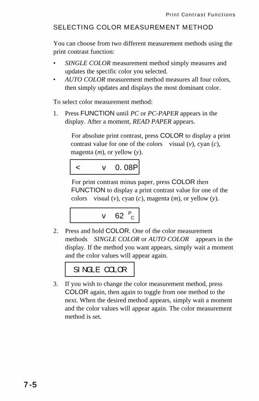
Print Contrast Functions
7-57-5
SELECTING COLOR MEASUREMENT METHOD
You can choose from two different measurement methods using theprint contrast function:
• SINGLE COLOR measurement method simply measures andupdates the specific color you selected.
• AUTO COLOR measurement method measures all four colors,then simply updates and displays the most dominant color.
To select color measurement method:
1. Press FUNCTION until PC or PC-PAPER appears in thedisplay. After a moment, READ PAPER appears.
For absolute print contrast, press COLOR to display a printcontrast value for one of the colorsvisual (v), cyan (c),magenta (m), or yellow (y).
For print contrast minus paper, press COLOR thenFUNCTION to display a print contrast value for one of thecolorsvisual (v), cyan (c), magenta (m), or yellow (y).
2. Press and hold COLOR. One of the color measurementmethodsSINGLE COLOR or AUTO COLORappears in thedisplay. If the method you want appears, simply wait a momentand the color values will appear again.
3. If you wish to change the color measurement method, pressCOLOR again, then again to toggle from one method to thenext. When the desired method appears, simply wait a momentand the color values will appear again. The color measurementmethod is set.
< v 0.08P
SINGLE COLOR
v 62 PC

418 Color Reflection Densitometer
7-67-6
Determining which Method is ActiveThe active color measurement method is indicated at the far leftwhen color measurement information appears in the display:
• When SINGLE is active, no characters are shown at the far left.• When AUTO is active, the characters “A” and “u” appear to the
far left of the display.
PRINT CONTRAST MEASUREMENT
So far, you have performed the procedures to select print contrastfunction, mode, and color measurement method.
You are now ready to begin taking measurements to check printcontrast values on your press sheet color bar. The type ofmeasurement data that will be displayed will depend on the way youset up your instrument earlier in this chapter. However, for allfunctions, modes, and methods, the measurement technique is thesame.
1. READ SOLID appears in the display.
2. Center target window over the solid patch.
3. Lower unit to target window and hold closed. Wait until soliddata is displayed. See example below. (If IF SOLID PRESS Zappears in the display or if the solid is displayed as a printcontrast value, press ZERO to measure the solid beforereleasing the unit.)
4. Once solid data is displayed, release the unit. Center targetwindow over the 75% tone that corresponds with the previouslymeasured solid.
5. Lower unit to target window and hold closed. Once printcontrast data is displayed, release the unit.
6. Repeat measuring solids and tones or remaining tones foradditional measurements.
[ v0.13P
READ SOLID
m 48.4PC
m .450s

Print Contrast Functions
7-77-7
Viewing Print Contrast Measurement DataThere are several different combinations of mode and methodsettings that will affect the way the measurement data is displayed.Since you just set up these parameters yourself, you should see thedata in the format you expect. For example, if you set yourinstrument parameters to AUTO and -PAPER, your measurementdata will appear like this :
“A” and “u” appear to the far left, indicating that the instrumentautomatically recognized the colorin our example, the color wascyan. And, the “Pc” after the value is underlined for print contrastminus paper; not underlined for absolute print contrastmeasurements.
Viewing Measurement Data for Each ColorYou can view measurement data in the display for one color at atime. To toggle the display view from one color’s measurement datato the next, press the COLOR button when data is displayed. Eachtime you press, the display switches from visual to cyan to magenta,and so forth.
If you are using the SINGLE or AUTO measurement method, thedata displayed for each color represents the last time that color wasmeasured .
EXAMPLE: Pressing the COLOR buttonrepeatedly toggles display from onecolor’s measurement data to the next.
[ c 1.13PC_
[ v 1.13PC_
[ c 1.17PC_
[ m 1.18PC_
[ y 1.02PC_

418 Color Reflection Densitometer
7-87-8
PRINT CONTRAST DIFFERENCE MEASUREMENT
Print contrast difference measurement uses the same parameters asprint contrast measurement. To set up for print contrast differencemeasurement, follow the procedures earlier in this chapter forselecting print contrast function, mode, and color measurementmethod.
To view measurement data as a print contrast difference valuebetween a measured sample and a known referenceinstead of theprint contrast value of the measured sampleyou must first enter areference measurement; and then activate the print contrastdifference (PC-REF or PC-PAPER-REF) display format.
Entering a Reference Measurement1. Before measuring your solid, press ZERO twice. REFERENCE
appears for a moment, followed by the current Reference value.If none has been entered, the Reference value is 0.00.
2. Select the desired ink by pressing COLOR.
3. To enter a reference valueor change the current referencevalueyou can either:measure the reference value directly; ormanually enter the reference value using the arrow buttonfunctions.
To measure the reference value directly:
Measure the color that you wish to use as the reference. Then,press FUNCTION to return to normal operation.
To enter the reference value manually:
Hold down the ZERO (ts) button, then press theFUNCTION (▼) or COLOR (▲)button to adjust the valueuntil the desired value is shown. Then, press FUNCTION toreturn to normal operation.
TIP: If you need to move the value up or down by a largeamount, hold the arrow button down. The numbers will advancefaster as you hold it down.
< y 16.9R

Print Contrast Functions
7-97-9
Activating Print Contrast Difference DisplayFormatOnce you have your reference measurement established and storedin the instrument’s memory, you now need to activate the printcontrast difference display format:
1. When you press FUNCTION and PC or PC-PAPER appears,press ZERO before the display switches to READ PAPER orthe first color value. -REF is added to the function. The displayreads either PC-REF if you are in absolute mode; or PC-PAPER-REF if you are in minus paper mode.
2. To de-activate density difference display format, repeat #1 toremove -REF from the function.
Viewing Print Contrast Difference MeasurementDataThere are several different combinations of mode and methodsettings that will affect the way the measurement data is displayed.Since you just set up these parameters yourself, you should see thedata in the format you expect. For example, if you set yourinstrument parameters to AUTO COLOR, -PAPER, and reference,your measurement data will appear like this:
“A” and “u” appear to the far left, indicating that the instrumentautomatically recognized the colorin our example, the color wascyan. The “r” indicates it is a reference measurement. And, the “Pc”after the value is underlined for print contrast minus papermeasurements, or not underlined for absolute print contrast.
A “negative” value indicates that the sample was measured to haveless print contrast than the reference. If a positive value appears, thesample was measured to have more print contrast than the sample.If 0.00 appears, the sample was measured to have the same printcontrast as the reference.
[ c 1.13rPC_

418 Color Reflection Densitometer
7-107-10

8-18-1
8 Hue Error &Grayness Functions
Formulas .................................. 8-1Selecting Hue Error/GraynessFunction.................................... 8-2Selecting Hue Error/GraynessMode ........................................ 8-3Hue Error/GraynessMeasurement............................ 8-5Hue Error/GraynessDifference Measurement........... 8-6
For hue error and grayness measurements, you need to set somemeasurement parameters. You need to select:
• the desired measurement function (hue error or grayness)(page 8-2);
• the desired measurement modeabsolute hue error/grayness,or hue error/grayness minus paper (page 8-3); and
• the desired measurement type—normal or minus reference(page 8-7).
• NOTE: All hue error/grayness function measurements areAUTO only.
FORMULAS
Hue error percentage is calculated as follows:
H =D D
D D100M L
H L
−−
×
Grayness percentage is calculated as follows:
G =D
DL
H
×100
Where:• DH = Highest density of R, G, or B.• DM = 2nd highest density of R, G, or B.• DL = Lowest density of R, G, or B.

418 Color Reflection Densitometer
8-28-2
SELECTING HUE ERROR/GRAYNESS FUNCTION
1. If this is your first time selecting a measurement function, youshould plug your instrument in using its AC adapter. This willprevent the microprocessor from going into “sleep” mode tosave battery power. With the instrument plugged in, you’ll befree to take your time learning this procedure.
2. Next, make sure you have the desired response setting selected,and that the instrument is properly calibrated. These proceduresare covered in the chapter 2, “Calibration.”
3. To select the measurement method for measuring hue error andgrayness, press the FUNCTION button repeatedly until H/Gappears in the display.
Now, you can choose to measure absolute hue error/grayness, whichwill read the hue error/grayness including the paper; or to measurehue error/grayness minus paper. You make this selection by settinghue error/grayness mode.
H/G

Hue Error & Grayness Functions
8-38-3
SELECTING HUE ERROR/GRAYNESS MODE
1. Press the FUNCTION button and the COLOR buttonsimultaneously, then release. NO cal T YES appears in thedisplay, where “T” represents Status response you selected (T,G, E, or N).
2. Press FUNCTION to indicate no, you do not want to calibrate.NO modes YES appears in the display.
3. Press ZERO to indicate yes, you do want to set mode.↓ RESPONSE T appears in the display.
4. Press FUNCTION to advance to ↓ OPERATION YES.
5. Press ZERO to indicate yes, you do want to set operations.↓ DEN ABSOLUTE appears in the display.
6. Press FUNCTION two times until H/G-PAPER or H/GABSOLUTE appears in the display.
7. Here is where you select hue error/grayness minus paper orabsolute hue error/grayness.
If you wish to select hue error/grayness minus paper, pressZERO until H/G-PAPER appears in the display. Then, simplypress FUNCTION until you exit mode selection. Minus papermode is already selected; H/G-PAPER appears in the displaybriefly, followed by READ PAPER.
If you wish to select absolute hue error/grayness, pressZERO until H/G ABSOLUTE appears in the display. Then,simply press FUNCTION until you exit mode selection.Absolute mode is already selected; H/G ABSOLUTE appears inthe display briefly, followed by a color value hue error orgrayness.
NO cal T YES
NO modes YES
^ RESPONSE T
^ OPERATION YES

418 Color Reflection Densitometer
8-48-4
Measurement mode is now selected. Absolute hue errormeasurement data will appear with a “H” after the value,grayness with a “G”; minus paper data is indicated by anunderlined letter “H” or “G” .
Measuring PAPER for Hue Error/GraynessWhen measuring hue error grayness minus paper, you must providea reading of the paper before taking color measurements. Theinstrument will take the value of the paper and automaticallysubtract it from subsequent color measurements. This paper valuemust be updated before every measurement sequence.
Once H/G-PAPER appears in the display, center the instrumenttarget window over a sample of the paper, then lower the instrumenthead to take a reading and hold.
• If the instrument recognizes the measurement as a paperreading, the display becomes ready for the first color reading.
• If the instrument does not recognize the measurement as apaper reading, IF PAPER PRESS Z appears.
Keep the instrument pressed down, then press ZERO toindicate that yes, this is the new paper value. Then, the displaybecomes ready for the first color reading.
READ PAPER
IF PAPER PRESS Z
56.0H 51.9Gcm
Indicates absolutehue
Indicates grayness minuspaper
51.9Hcm 51.9G
cm _

Hue Error & Grayness Functions
8-58-5
HUE ERROR/GRAYNESS MEASUREMENT
So far, you have performed the procedures to select the correct trapformula and trap function.
You are now ready to begin taking measurements to check trapvalues on your press sheet color bar. The type of measurement datathat will be displayed will depend on the way you set up yourinstrument earlier in this chapter.
However, for all functions, modes, and methods, the measurementtechnique is the same. Simply:
1. Center target window over area to be measured.
2. Lower unit to target window and hold closed.
3. Once measurement data is displayed, release the unit.
4. Measurement data will appear either as a normal hue error orgrayness value (absolute or minus paper).

418 Color Reflection Densitometer
8-68-6
HUE ERROR/GRAYNESS DIFFERENCEMEASUREMENT
Hue error/grayness difference measurement uses the sameparameters as hue error/grayness measurement. To set up for hueerror/grayness difference measurement, follow the procedures earlierin this chapter for selecting hue error/grayness function, mode, andcolor measurement method.
To view measurement data as a hue error/grayness difference valuebetween a measured sample and a known referenceinstead of thehue error/grayness values of the measured sampleyou must firstenter a reference measurement; and then activate the hueerror/grayness difference (H/G-REF or H/G-PAPER-REF) displayformat.
Activating Hue Error/Grayness Difference DisplayFormatBefore creating your reference measurement, you need to activatethe hue error/grayness difference display format:
1. When you press FUNCTION and H/G or H/G-PAPER appears,press ZERO before the display switches to READ PAPER orthe first color value. -REF is added to the function. The displayreads either H/G-REF if you are in absolute mode; or H/G-PAPER-REF if you are in minus paper mode.
2. To de-activate density difference display format, repeat #1 toremove -REF from the function.
Entering a Reference MeasurementNow that Reference measurement is activated, you need to enter areference into the instrument’s memory.
1. Press FUNCTION until H/G-REF or H/G-PAPER-REFdisplays.
2. READ PAPER appears.
3. Measure paper. READING H/G displays momentarily, followedby the paper values. When the read head is released, theprevious hue error/grayness measurement values display.
4. Press ZERO. REFERENCE appears for a moment, followed bythe current Reference value. If none has been entered, theReference value is 0.00.

Hue Error & Grayness Functions
8-78-7
5. Select the desired ink combination by pressing COLOR.
6. To enter a reference valueor change the current referencevalueyou can either:measure the reference value directly; ormanually enter the reference value using the arrow buttonfunctions.
To measure the reference value directly:
Measure the color that you wish to use as the reference. Then,press FUNCTION to return to normal operation.
To enter the reference value manually:
The cursor will be under the “Hr.” If entering the hue errorreference values continue with the next step. If entering thegrayness reference values, press ZERO once to move the cursorunder the “Gr” and continue with the next step.
Hold down the ZERO (ts) button, then press theFUNCTION (▼) or COLOR (▲)button to adjust the valueuntil the desired value is shown. Then, press FUNCTION toreturn to normal operation.
TIP: If you need to move the value up or down by a largeamount, hold the arrow button down. The numbers will advancefaster as you hold it down.
< 39 50Ym
Hr
Gr

418 Color Reflection Densitometer
8-88-8
Viewing Hue Error/Grayness Measurement DataHue error and grayness value color is displayed as color over colorat the far left—v (visual), c (cyan), m (magenta), y (yellow)—followed by the hue error and grayness value and mode designation.
For example, “m” above “y” appearing to the far left, indicates thatthe color is magenta towards yellow. The “H” after the valueindicates that it is a hue error value, the “G” indicates it is agrayness value—underlined for hue error/grayness minus papermeasurements, or not underlined for absolute hue error/grayness.An “r” before the “H” or “G” indicates a reference calculation.
To switch between the color combinations (on the left), pressCOLOR.
56.0rH20.1rG
mY

9-19-1
9 Hue Error &Saturation Functions
Formulas .................................. 9-1Selecting Hue Error/SaturationFunction.................................... 9-2Selecting Hue Error/SaturationMode ........................................ 9-3Hue Error/SaturationMeasurement............................ 9-5Hue Error/SaturationDifference Measurement........... 9-6
For hue error and saturation measurements, you need to set somemeasurement parameters. You need to select:
• the desired measurement function (hue error or saturation)(page 8-2);
• the desired measurement modeabsolute hue error/saturation,or hue error/grayness minus paper (page 8-3); and
• the desired measurement type—normal or minus reference.• NOTE: All hue error/grayness function measurements are
AUTO only.
FORMULAS
Hue error percentage is calculated as follows:
H =D D
D D100M L
H L
−−
×
Saturation is calculated as follows:
S = DH - DL
Where:
• DH = Highest density of R, G, or B-P*.• DM = 2nd highest density of R, G, or B-P*.• DL = Lowest density of R, G, or B-P*.* Or absolute as set by modes.

418 Color Reflection Densitometer
9-29-2
SELECTING HUE ERROR/SATURATION FUNCTION
1. If this is your first time selecting a measurement function, youshould plug your instrument in using its AC adapter. This willprevent the microprocessor from going into “sleep” mode tosave battery power. With the instrument plugged in, you’ll befree to take your time learning this procedure.
2. Next, make sure you have the desired response setting selected,and that the instrument is properly calibrated. These proceduresare covered in the chapter 2, “Calibration.”
3. To select the measurement method for measuring hue error andsaturation, repeatedly press FUNCTION until H/G is displayed.
4. READ PAPER will display. Read paper and release head.
5. Press and hold COLOR until GRAYNESS appears.
6. Press COLOR repeatedly to toggle between SATURATION andGRAYNESS.
7. When SATURATION is displayed, repeatedly pressFUNCTION until H/S is displayed.
You can choose to measure absolute hue error/saturation, whichwill read the hue error/saturation including the paper; or to measurehue error/saturation minus paper. You make this selection by settinghue error/saturation mode.
GRAYNESS
SATURATION
H/S

Hue Error & Saturation Functions
9-39-3
SELECTING HUE ERROR/SATURATION MODE
1. Press the FUNCTION button and the COLOR buttonsimultaneously, then release. NO cal T YES appears in thedisplay, where “T” represents Status response you selected (T,G, E, or N).
2. Press FUNCTION to advance to ↓ OPERATION YES.
3. Press ZERO to indicate yes, you do want to set operations.↓ DEN ABSOLUTE appears in the display.
4. Press FUNCTION two times until H/S-PAPER or H/SABSOLUTE appears in the display.
7. Here is where you select hue error/saturation minus paper orabsolute hue error/saturation.
If you wish to select hue error/saturation minus paper, pressZERO until H/S-PAPER appears in the display. Then, simplypress FUNCTION until you exit mode selection. Minus papermode is already selected; H/S-PAPER appears in the displaybriefly, followed by READ PAPER.
If you wish to select absolute hue error/saturation, pressZERO until H/S ABSOLUTE appears in the display. Then,simply press FUNCTION until you exit mode selection.Absolute mode is already selected; H/S ABSOLUTE appears inthe display briefly, followed by a color value hue error orgrayness.
Measurement mode is now selected. Absolute hue errormeasurement data will appear with a “H” after the value,saturation with an “S”, and grayness with a “G”; minus paperdata is indicated by an underlined letter “H,” “S,” or “G” .
Indicates absolutehue and saturation
Indicates hue error andgrayness minus paper
4.9H 0.03SYm 4.0H 76.9G
Ym
H/S ABSOLUTE
^ DEN ABSOLUTE
H/SPAPER

418 Color Reflection Densitometer
9-49-4
Measuring PAPER for Hue Error/SaturationWhen measuring hue error/saturation minus paper, you mustprovide a reading of the paper before taking color measurements.The instrument will take the value of the paper and automaticallysubtract it from subsequent color measurements. This paper valuemust be updated before every measurement sequence.
Once H/S-PAPER appears in the display, center the instrumenttarget window over a sample of the paper, then lower the instrumenthead to take a reading and hold.
• If the instrument recognizes the measurement as a paperreading, the display becomes ready for the first color reading.
• If the instrument does not recognize the measurement as apaper reading, IF PAPER PRESS Z appears.
Keep the instrument pressed down, then press ZERO toindicate that yes, this is the new paper value. Then, the displaybecomes ready for the first color reading.
READ PAPER
IF PAPER PRESS Z
4 H 0.03SYm

Hue Error & Saturation Functions
9-59-5
HUE ERROR/SATURATION MEASUREMENT
So far, you have performed the procedures to select the correct trapformula and trap function.
You are now ready to begin taking measurements to check trapvalues on your press sheet color bar. The type of measurement datathat will be displayed will depend on the way you set up yourinstrument earlier in this chapter.
However, for all functions, modes, and methods, the measurementtechnique is the same. Simply:
1. Center target window over area to be measured.
2. Lower unit to target window and hold closed.
3. Once measurement data is displayed, release the unit.
4. Measurement data will appear either as a normal hue error orsaturation value (absolute or minus paper).

418 Color Reflection Densitometer
9-69-6
HUE ERROR/SATURATION DIFFERENCEMEASUREMENT
Hue error/saturation difference measurement uses the sameparameters as hue error/saturation measurement. To set up for hueerror/saturation difference measurement, follow the proceduresearlier in this chapter for selecting hue error/saturation function,mode, and color measurement method.
To view measurement data as a hue error/grayness difference valuebetween a measured sample and a known referenceinstead of thehue error/grayness values of the measured sampleyou must firstenter a reference measurement; and then activate the hueerror/grayness difference (H/S-REF or H/S-PAPER-REF) displayformat.
Activating Hue Error/Saturation Difference DisplayFormatBefore creating your reference measurement, you need to activatethe hue error/saturation difference display format:
1. When you press FUNCTION and H/S or H/S-PAPER appears,press ZERO before the display switches to READ PAPER orthe first color value. -REF is added to the function. The displayreads either H/S-REF if you are in absolute mode; or H/S-PAPER-REF if you are in minus paper mode.
2. To de-activate density difference display format, repeat step 1 toremove -REF from the function.
Entering a Reference MeasurementNow that Reference measurement is activated, you need to enter areference into the instrument’s memory.
1. Press FUNCTION until H/S-REF or H/S-PAPER-REF displays.
2. READ PAPER appears.
3. Measure paper. READING H/S displays momentarily, followedby the paper values. When the read head is released, theprevious hue error/grayness measurement values display.
H/S H/SREF
.049 .046 .060P 37@0H @131SrY

Hue Error & Saturation Functions
9-79-7
4. Press ZERO. REFERENCE appears for a moment, followed bythe current Reference value. If none has been entered, theReference value is 0.00.
5. Select the desired ink combination by pressing COLOR.
6. To enter a reference valueor change the current referencevalueyou can either:measure the reference value directly; ormanually enter the reference value using the arrow buttonfunctions.
To measure the reference value directly:
Measure the color that you wish to use as the reference. Then,press FUNCTION to return to normal operation.
To enter the reference value manually:
The cursor will be under the “Hr.” If entering the hue errorreference values continue with the next step. If entering thegrayness reference values, press ZERO once to move the cursorunder the “Sr” and continue with the next step.
Hold down the ZERO (ts) button, then press theFUNCTION (▼) or COLOR (▲)button to adjust the valueuntil the desired value is shown. Then, press FUNCTION toreturn to normal operation.
TIP: If you need to move the value up or down by a largeamount, hold the arrow button down. The numbers will advancefaster as you hold it down.
< 39Hr 50S
r
Ym

418 Color Reflection Densitometer
9-89-8
Viewing Hue Error/Saturation MeasurementDataHue error and grayness value color is displayed as color overcolor at the far left—v (visual), c (cyan), m (magenta), y(yellow)—followed by the hue error and grayness value andmode designation.
For example, “m” above “y” appearing to the far left, indicatesthat the color is magenta towards yellow. The “H” after thevalue indicates that it is a hue error value, the “S” indicates it isa grayness value—underlined for hue error/saturation minuspaper measurements, or not underlined for absolute hueerror/grayness. An “r” before the “H” or “S” indicates areference calculation.
To switch between the color combinations (on the left), pressCOLOR.
56.0rH20.1rS
mY

10-110-1
10 Cast/Brightnessand ReflectanceFunctions
Cast/Brightness Formulas ....... 10-1Selecting Cast/Brightness orReflectance Function .............. 10-2Cast/Brightness orReflectance Measurement ...... 10-3Cast/BrightnessDifference Measurement......... 10-3
Reflectance is a measurement of light reflected off a sample in thethree color channels. Cast is the difference between the highest andlowest of the red, green, and blue reflectances. Brightness is equalto the blue reflectance. To view reflectance or cast/brightness, youneed to set some measurement parameters. You need to select:
• the desired viewing mode—reflectance or cast andbrightness; and
• the desired measurement value—difference or normal.• NOTE: The percentage of cast, brightness, and reflectance are
updated after every measurement.
FORMULAS
Cast percentage is calculated as follows:
C = RL – RH
Brightness percentage is calculated as follows:
B = Rb
Where:
RL = lowest reflectance of Rr, Rg, or Rb
RH = highest reflectance of Rr, Rg, or Rb
Rb = blue reflectance

418 Color Reflection Densitometer
10-210-2
SELECTING CAST/BRIGHTNESS ORREFLECTANCE FUNCTIONS
1. If this is your first time selecting a function, you should plugyour instrument in using its AC adapter. This will prevent themicroprocessor from going into “sleep” mode to save batterypower. With the instrument plugged in, you’ll be free to takeyour time learning this procedure.
2. Next, make sure you have the desired response setting selected,and that the instrument is properly calibrated. These proceduresare covered in the chapter 2, “Calibration.”
3. To select the viewing method for reflectance or cast andbrightness , repeatedly press FUNCTION untilREFLECTANCE or CAST/BRIGHT is displayed.
4. If you want to measure reflectance and REFLECTANCE isdisplayed, or if you want to measure cast/brightness andCAST/BRIGHT is displayed, go to step 9.
5. If you want to choose reflectance and CAST/BRIGHT isdisplayed, or if you want to choose cast/brightness andREFLECTANCE is displayed, go to step 1 below.
6. When either CAST/BRIGHT or REFLECTANCE is displayed,READ PAPER appears. Measure paper and release read head.
7. With either cast/brightness or reflectance values displayed,press COLOR momentarily.
8. Press FUNCTION repeatedly until your desired setting, eitherCAST/BRIGHT or REFLECTANCE, is displayed.
CAST/BRIGHT
4 C 2 BrY 7 3 2 r
F

Cast/Brightness & Reflectance Functions
10-310-3
CAST/BRIGHTNESS OR REFLECTANCEMEASUREMENT
1. With your desired setting selected, READ PAPER appears.
2. Measure paper and release head. READING C/B or READINGREFL is displayed during measurement.
3. When the read head is lifted, the values are displayed. PressingCOLOR switches between cast/brightness values andreflectance values.
CAST/BRIGHTNESS DIFFERENCE MEASUREMENT
Cast/brightness difference measurement uses the same parameters ascast/brightness measurement. To set up for cast/brightnessdifference measurement, follow the procedures earlier in thischapter for selecting cast/brightness function, mode, and colormeasurement method.
To view measurement data as a cast/brightness difference valuebetween a measured sample and a known referenceinstead of thecast/brightness values of the measured sampleyou must firstactivate the cast/brightness difference (CAST/BRIGHT-REF)display format; and then enter a reference measurement.
Activating Cast/Brightness Difference DisplayFormatBefore you can view a reference value, reference measurement mustbe activated.
1. Press FUNCTION until CAST/BRIGHT displays.
2. Press ZERO before READ PAPER appears. CAST/BRIGHT-REF will display.
3. To de-activate density difference display format, repeat steps 1and 2 to remove -REF from the function.
6 3 2rF 4rC 2rB
rY
READING C/B 4 C 2 BrY
CAST/BRIGHT CAST/BRIGHTREF

418 Color Reflection Densitometer
10-410-4
Entering a Reference MeasurementNow that Reference measurement is activated, you need to enter areference into the instrument’s memory.
1. Press FUNCTION until CAST/BRIGHT-REF displays.
2. READ PAPER appears.
3. Measure paper. READING C/B displays momentarily, followedby the paper values. When the read head is released, theprevious cast/brightness measurement values display.
4. Press ZERO. REFERENCE appears for a moment, followed bythe current Reference value. If none has been entered, theReference value is 0.00.
5. To enter a reference valueor change the current referencevalueyou can either:measure the reference value directly; ormanually enter the reference value using the arrow buttonfunctions.
To measure the reference value directly:
Measure the color that you wish to use as the reference. Then,press FUNCTION to return to normal operation.
To enter the reference value manually:
The cursor will be under the “Cr.” If entering the cast referencevalues continue with the next step. If entering the brightnessreference values, press ZERO once to move the cursor underthe “br” and continue with the next step.
Hold down the ZERO (ts) button, then press theFUNCTION (▼) or COLOR (▲)button to adjust the valueuntil the desired value is shown. Then, press FUNCTION toreturn to normal operation.
CAST/BRIGHTREF
11@2C 68@9BYc
REFERENCE < 13.9cr 18.4br

Cast/Brightness & Reflectance Functions
10-510-5
TIP: If you need to move the value up or down by a largeamount, hold the arrow button down. The numbers will advancefaster as you hold it down.
Viewing Cast/Brightness and ReflectanceMeasurement DataCast and brightness value is displayed as color over color at thefar left—v (visual), c (cyan), m (magenta), y (yellow), r (red), g(green), b (blue)—followed by the cast and brightness value andmode designation.
For example, “g” above “y” appearing to the far left, indicatesthat the color is green towards yellow. The “C” after the valueindicates that it is a cast value, the “B” indicates it is abrightness value. An “r” before the “C” and “B” indicates areference calculation.
Reflectance values display the percentage of reflectance for thethree color channels. Cyan, magenta, and yellow reflectancevalues are listed from left to right in the display.
3rC 81rBGY

418 Color Reflection Densitometer
10-610-6

11-111-1
n – A
n
11 Statistics
Formulas ................................ 11-1Mean ...................................... 11-2Sigma ..................................... 11-3Range..................................... 11-4
The EFSTM, NEFSTM, cast/brightness, and reflectance functions eachhave the ability to perform several statistical calculations—mean(µ), 1 or 2 sigma (σ), or range. Statistics calculations are clearedwhenever paper is measured after READ PAPER is displayed.Otherwise, statistical calculations are always being performed andcan be displayed as described on the next page.
FORMULAS
µ = Average = Σx
σ = ( Σx2 – nµ2
)1/2
Range = Dmax – Dmin
Where:Σx2 = sum of x2
x = measurementn = number of measurementsA = 0, for σ1 (standard) Õ 68% of measurement
1, for σ2 (sample) Õ 95% of measurement
µ−2σ µ−1σ µ+1σ µ+2σµ
68%95%

418 Color Reflection Densitometer
11-211-2
MEAN µµ
To activate mean (in EFSTM, NEFSTM, cast/brightness, or reflectancemodes only):
1. With measurement on display, press and hold COLOR untilNORMAL OPERATION is displayed.
2. Momentarily press COLOR. Mean is displayed. Wait untildisplay reverts to data.
3. Measure Patch. The actual value of the patch is shown when thehead is down. The example shown is in Cast/Brightness mode.
4. The mean value and measurement count are displayed when theread head is lifted. Mean is activated when µ is shown in thedisplay.
MEAN µ nF µy @000O
4.5C 85.7B
4.3µ 86.11
NORMAL OPERATION
Ym
Ym

Statistics
11-311-3
|
σ ||
σ
|
σ
|
σ
|
σ
SIGMA σσ
To activate 1σ or 2σ (in EFSTM, NEFSTM, cast/brightness, orreflectance modes only):
1. With measurement value on display, press and hold COLORuntil NORMAL OPERATION is displayed.
2. Repeatedly press COLOR key until STANDARD DEV σ isdisplayed. After a moment, data will display. The exampleshown is in Cast/Brightness mode.
3. Select 1σ or 2σ by repeatedly depressing ZERO.
4. Wait until the screen displays data. Measure patch.
5. Actual data is displayed with the read head down. The selectedsigma value and measurement count are displayed when theread head is lifted. Sigma is activated when or is shown inthe display.
0.1 0.21
STANDARD DEV. SAMPLE DEV. ||
σ
E
F V V @000l
Ym

418 Color Reflection Densitometer
11-411-4
RANGE
To activate range (in EFSTM, NEFSTM, cast/brightness, orreflectance modes only):
1. With the measurement value on display, press and holdCOLOR until NORMAL OPERATION is displayed.
2. Repeatedly press COLOR until RANGE r is displayed.
3. Wait until the screen displays data. Measure patch.
4. Actual data is displayed with the read head down. The rangevalue and measurement count is displayed when read head islifted. Range is activated when r is shown in the display.
NOTE: Dmin and Dmax values used to calculate range are onlyavailable to view through printout.

12-112-1
12 Technical Information
Serial Interface Information..... 12-1Instrument Specifications........ 12-4Factory Presets....................... 12-6Accessories ............................ 12-7General Cleaning.................... 12-8Optics Maintenance ................ 12-8Target Window Replacement.. 12-9Lamp Replacement................ 12-10
SERIAL INTERFACE INFORMATION
The connector used for serial input/output is a Modular 10 circuittype. Figure 9-1 is the connection diagram.
Figure 9-1
418

418 Color Reflection Densitometer
12-212-2
An RS232 to modular interface adapter is available from X-Ritewhich performs as shown in the diagram on the previous page. Thisadapter also provides a jack for the AC adapter so that only onecable need be connected to the 428. Also, when the adapter is notconnected to the jack, the +V CHARGER is connected to pin 9 ofthe DB25 in the diagram. The charger ground is connected to thejack ground only.The part numbers for these interface adapters are: P/N 428-70 (maleDB25 connector) P/N 428-71 (female DB25 connector) See“Accessories” later in this chapter for other adapters.
A 10-foot modular to modular cable for connection of the 428 to theinterface adapter is available by ordering P/N SE108-69.
Term DefinitionsPin 2 Transmitted Data: Data transmitted from the densitometerwith parameters (baud rate, format) set by the densitometer.
Pin 3 Received Data: Data received by the densitometer fromoutside source using the same parameters as the densitometer.
Pin 4 DTR (Data Terminal Ready): Logic 0 active (On Line) andLogic 1 during: Power Off, Power Up, Self Test, duringmeasurements, and when serving RCI.
Pin 5 PIN 5 is set to CTS=logic 0 active; if set to BUSY=logic 1active; and if set to OFF=ignored.
Pin 7: This pin is used for supplying 12VDC @ 700ma for chargingthe 428 without having the Adapter connected directly to the unit.
Input CharacteristicsLogic 1=+.8VDC to -25VDCLogic 0=+2.25VDC to +25VDC
Output CharacteristicsLogic 1=approximately -4VDCLogic 0 = approximately +5VDC
Outputs are @ 0VDC during Power Down.

Statistics
12-312-3
A typical interconnection between the 428 and a computerin itssimplest form is shown in Figure 9-2.
Figure 9-2
2
Serial OutputThe data format that is transmitted from the 428 is determined bythe I/O PORT options found in Chapter 1 under “I/O Port Setup.”
Data transmitted by the 428 shall have one start bit (Logic 0), 7 bitsof ASCII, one parity bit (set to Logic 0), and then one stop bit (Logic1).
Serial Input CommandsYour 428 is equipped with an input that allows the 428 to becontrolled or monitored remotely. Every function that can beperformed by the 428 (plus a few special functions not activated bythe keyboard) can be activated via the serial input. This RemoteControl Interface is covered by U.S. Patent 4,591,978.
For more information on Serial Input Commands and remotecontrol operation of the 428, order the Serial Interface Manual, P/N428-506, from X-Rite, Incorporated.

418 Color Reflection Densitometer
12-412-4
INSTRUMENT SPECIFICATIONS
DisplayDot Matrix LCD
Measuring GeometryANSI PH 2.17/DIN 16536 multi-sensor array
Light SourceFilament bulb 3000°K DIN approx. 2856°K ANSI
ReceiverSilicon Photodiode
Color ResponseG optics for X-Rite Graphics Art Response w/ ANSI Status TComputerized Color Response.
E optics w/47B per DIN16536 w/Glass interference typeComputerized Color Response.
Measuring Range0.00D-2.5D for G & E0.00D-2.20D for GS, ES, G/LP, & E/LP0-100% dot
Reproducibility±0.01D±1% for dot area (10-100%)
Linearity±0.01D or ±1%
Inter-Instrument Agreement±0.02D or ±2%
Aperture Diameter428G,E3.4mm428GS,ES1.7mm
CalibrationAutomatic with Quick Cal™Adjusts Zero and Slope for DensityComputerized Color Response™

Statistics
12-512-5
Polarization Filter2 x linear /LP option
Warm Up TimeNone
Zero Stability±.01D maximum per 8 hours
Slope Stability±1% maximum per year
Power SupplySix rechargeable AA NiCad batteries 7.2v total rated @600m Ah(included)
Charge TimeApproximately 14 hours
AC Adapter Requirements428 90-130VAC, 50-60Hz, 18W Maximum428X 180-260VAC, 50-60Hz, 20W Maximum12VDC @ 700ma, Positive tip
Operating Temperature Range50°-104°F /10°-40°C
Measurements Per ChargeApprox. 4500 (usage dependent)
Measuring TimeApproximately 0.6 seconds
Weight800 grams
Dimensions7.4cm H x 8.cm W x 19.6cm L

418 Color Reflection Densitometer
12-612-6
FACTORY PRESETS
The following settings were set in your instrument at the factory. Tochange these, see chapter 1.
Response428G, GS, G/LP G response428E, ES, E/LP E response
Operation SelectionDensity 428G, GS, G/LP: Absolute density
428E, ES, E/LP: Minus paper
Print Contrast 428G, GS, G/LP: Minus paper428E, ES, E/LP: Minus paper
Hue Error/ Grayness 428G, GS, G/LP: Minus paper428E, ES, E/LP: Minus paper
Dot “n” Factor 428G, GS, G/LP: 1.00428E, ES, E/LP: 1.00
Trap Preucil
Electronic Function EFS: Heat setSelect EFS 3C: Density
EFS Ref3: DotEFS OP: Trap
ToleranceTolerance: Off
X10X10: Off
I\O Port SetupRCI: OnRef. Print: OffPin 5: OffBaud: 1200Prnt Hdr: OffDec. Pt: OnCR: With LF (carriage return with line feed)Comp: OnXon/Xoff: Off

Statistics
12-712-7
ACCESSORIES
Accessories IncludedColor Reflection ReferenceOperation ManualAC AdapterCarrying Case
Specifications and design subject to change without notice.
Accessories and Replacement Parts AvailablePolarization Filter..........................................................P/N 428-73Security Cable ...............................................................P/N 428-751.7mm Target Window................................... P/N 428-21-017-KIT3.4mm Target Window................................... P/N 428-21-034-KIT1.7mm Aperture .....................................................P/N 428-63-0173.4mm Aperture .....................................................P/N 428-63-034Lamp Assembly.............................................................P/N 428-13G Optics.....................................................................P/N 428G-35G/LP Optics ......................................................... P/N 428G/LP-35GS Optics.................................................................P/N 428GS-35E Optics ..................................................................... P/N 428E-35E/LP Optics...........................................................P/N 428E/LP-35ES Optics ................................................................. P/N 428ES-35Modular Interconnect Cable ..................................... P/N SE108-69DB25P DCE (Null Modem) Interface Adapter...............P/N 428-70DB25S DCE (Null Modem) Interface Adapter...............P/N 428-71DB25P DTE (Normal) Interface Adapter ......................P/N 428-80DB25S DTE (Normal) Interface Adapter.......................P/N 428-81DB9P Interface Adapter ................................................P/N 428-90DB9S Interface Adapter ................................................P/N 428-91Modular Interconnect Cable for Macintosh® computerswith 8 pin mini-DIN connector......................................P/N 428-79
For further information on accessories contact your X-Riterepresentative or call X-Rite, Inc. at: 1-888-826-3061.

418 Color Reflection Densitometer
12-812-8
GENERAL CLEANING
The exterior of the instrument can be wiped clean with a clothdampened in water or a mild cleaner whenever required.
NOTE: Do not use any solvents to remove ink from the cover.
OPTICS MAINTENANCE
1. Remove Optics assembly by removing sensor nose screws fromdensitometer housing, and then lifting the assembly upward.(Figure 9-3)
Figure 9-3
2. Remove three inner screws [1] on sensor nose [2] and rotateOptics over carefully so sensor nose [2] is at bottom.
3. Carefully lift up Optics assembly [4] separating from sensornose [2].
4. Clean Optics sensors with camelhair brush and set aside.
5. Carefully remove IR Glass [3] and optional polarizing filter (ifinstalled) from sensor nose [2].
6. Remove dust and lint from inner sensor nose and filter(s) withcamelhair brush.
5
4
3
2
1

Statistics
1212--99
7. Carefully reinstall optional polarizing filter (if used) and IR Glass [3] (holding both by edges) into sensor nose, making sure filter(s) are properly seated.
8. Align flat edge of sensor nose [2] with flat edge on Lamp assembly P.C.B [5] and secure sensor nose [2] to Optics assembly [4] with three inner screws [1].
9. Carefully reinstall Optics assembly into densitometer by facing flat edge of sensor nose to front of densitometer. Work into position until alignment pins and connector pins are properly seated.
10. Insert and tighten sensor nose screws.
TARGET WINDOW REPLACEMENT
1. Remove old target window by pushing downward on top of shoe [1]. Clean off any remaining adhesive from shoe. (Figure 9-4)
Figure 9-4
2. Turn densitometer over and compress shoe [1] all the way down, and lock shoe.
3. Remove paper backing from tape strip on new target window [2], and remove clear film from opposite side of new target window.
4 2
1
3

418 Color Reflection Densitometer
1212--1010
4. Place one taped edge of target window [2] on indent [4] at bottom of shoe [1].
5. Align hole of target window [2] exactly in center of hole in sensor nose [3] and press remaining three sides of target window into place.
6. Unlock shoe.
LAMP REPLACEMENT
Lamp Removal 1. Remove Optics assembly by removing sensor nose screws [1]
from the densitometer housing, and then lifting assembly upward. THE THREE INNER SCREWS ON SENSOR NOSE ARE NOT TO BE REMOVED. (Figure 9-5)
Figure 9-5
2. Once Optics assembly is free, rotate over and remove two screws
[4] from the lamp PCB [3]. (Figure 9-6)
Densitometer Housing
1

Statistics
12-1112-11
Figure 9-6
3. Carefully remove old Lamp assembly [3] by lifting upward anddiscarding.
Lamp Installation1. Align the flat edges of Optics PCB [2] and new Lamp PCB [3],
and insert into Optics assembly. (figure 9-6)
NOTE: EXTREME CAUTION MUST BE TAKEN WHENINSTALLING NEW LAMP. DO NOT BEND LAMP LEADS.
2. Insert and tighten the two lamp screws [4].
3. Carefully reinstall Optics assembly into densitometer by facingflat edge of sensor nose to front of densitometer. Work intoposition until alignment pins and connector pins are properlyseated.
4. Insert and tighten sensor nose screws [1]. (Figure 9-5)
4
3
2

418 Color Reflection Densitometer
12-1212-12

418 Color Reflection Densitometer
13-613-6
13 Appendixand Index
Display Messages ................... 13-1Proprietary Notice ................... 13-3Limited Warranty .................... 13-4Index ...................................... 13-5
MISCELLANEOUS DISPLAY MESSAGES
During normal operation, some additional display messages mayappear. Following are these messages, what these messages meanand what action must be taken when they appear.
BATTERY TOO LOW indicates that the batteries are getting lowand will soon need to be charged. BAT LO only appears while themeasurement is in progress. Once BAT LO is displayed, you willhave approximately 100-200 measurements remaining beforecharging is required.
CHARGE BATTERIES indicates that the batteries are too low tooperate the unit and must be recharged. CHARGE does not appearuntil you begin the recharge cycle. Thereafter, the unit will befunctional and all previous data will be accessible.
DEN TOO HIGH indicates density value measured is too high.Make sure you are measuring the right color for the measurementsequence and try again.
DEN TOO LOW indicates density value measured is too low.Make sure you are measuring the right color for the measurementsequence and try again.
If DEN TOO HIGH or DEN TOO LOW continues to appear, re-calibrate the instrument using long calibration (see Chapter 2).
INVALID READING When the unit is not held down longenough during a measurement, INVALID will display.
READ LAMP FAIL Measurement lamp has failed. The lampshould be examined and replaced. When this message occurs, you

418 Color Reflection Densitometer
13-213-2
can get out of this condition (after replacing lamp) by pressingFUNCTION then COLOR then FUNCTION or waiting until unitpowers down.
MEMORY TEST FAIL (Displayed only during power-up)Internal lithium battery is failing. Intermittent connection on Ni-Cad batteries.
PLEASE CALIBRATE Calibration has been lost. The instrumentneeds calibration.
READ PAPER Indicates that the next measurement should bepaper. If you do not measure paper, “PAPER? Z” will be displayedduring the measurement.
IF PAPER PRESS Z (Displayed during measurement) At thispoint the 428 is asking if this is a new paper value. If it is a newpaper value, momentarily press ZERO before releasing the readhead. If no, release the read head and the display will show normaloperation.
READ SOLID Indicates that a measurement on a solid ink densityis necessary. The solid should be measured first, followed by theappropriate tone.
IF SOLID PRESS Z The 428 is asking if the area measured is asolid. This message appears with a measurement on an overprint, ornon-process ink. It also appears when measuring a dot value of 80%or greater, and ZERO is pressed. If the area measured is intended tobe a solid, momentarily press ZERO before releasing the read head.If no, release the read head, numeric data plus O.P. (overprint), ordot value is displayed.
IF CMY PRESS Z The 428 is asking if the area measured is a 3color (gray balance). When measuring a 3 color patch and a visualvalue and IF CMY PRESS Z is displayed, press ZERO. If area beingmeasured is intended to be 3 color, momentarily press ZERO beforereleasing read head. If not, release read head and visual value isdisplayed.

Appendix and Index
13-313-3
PROPRIETARY NOTICE
The information contained in this manual is derived from patentand proprietary data from X-Rite, Incorporated. This manual hasbeen prepared expressly for the purpose of assisting operation andmaintenance personnel in their use and general maintenance of theX-Rite 428.
Publication of this information does not imply any rights toreproduce or use it for purposes other than installing, operating, ormaintaining the equipment described herein.
This instrument is covered by one or more of the following U.S.patents: #4,080,075; #4,591,978; #5,015,098; and patents pending.Foreign patent numbers provided on request.
THESE PROVISION ARE INTENDED TO STATE ALL OFTHE RIGHTS AND RESPONSIBILITIES BETWEEN X-RITE,INCORPORATED AND CUSTOMER. THEY TAKE PLACE OFAND SUPERSEDE ALL WARRANTIES, EXPRESSED ORIMPLIED, AND WHETHER OF MERCHANTABILITY, FITNESSOR OTHERWISE. THE REMEDIES CONTAINED IN THISOPERATION AND INSTALLATION MANUAL AREEXCLUSIVE.
CUSTOMER AND X-RITE, INCORPORATED WAIVE ALLOTHER REMEDIES, INCLUDING BUT NOT LIMITED TO,CONSEQUENTIAL DAMAGES.

418 Color Reflection Densitometer
13-413-4
LIMITED WARRANTY
X-Rite, Incorporated warrants each instrument manufactured bythem to be free of defects in material and workmanship for a periodof 12 months. THERE ARE NO WARRANTIES OFMERCHANTABILITY OR FITNESS. THIS WARRANTYOBLIGATION IS LIMITED TO SERVICING THE UNITRETURNED TO THE FACTORY FOR THAT PURPOSE ANDEXCLUDES THE LAMP AND NICAD BATTERIES.
The instrument shall be returned with transportation chargesprepaid. If the fault has been caused by misuse or abnormaloperating conditions, repairs will be billed at a nominal cost. In thiscase, an estimate will be submitted before work is started, ifrequested.
A Warranty Registration Card is enclosed with each instrument.The purchaser should fill in the card completely and return it to X-Rite, Incorporated postmarked no later than ten (10) days from thedate of receipt. This card registers your system with us for warrantycoverage. Once your unit is registered, we are able to maintain a fileto help expedite service in case it is needed.
Always include serial number and place of purchase in anycorrespondence concerning your instrument. The serial number islocated at the rear of the instrument.
X-Rite, Incorporated offers a repair program for instruments out ofwarranty. For more information, contact X-Rite Technical ServicesDepartment.
This agreement shall be interpreted in accordance with the laws ofthe State of Michigan and jurisdiction and venue shall lie with thecourts of Michigan as selected by X-Rite, Incorporated.

Appendix and Index
13-513-5
Index
Accessories, 12-8
Adjusting the display angle, 1-9
Batteries and Power, 1-6, 1-8
Brightness percentage, 10-2
Brunner Trap formula, 6-1
Calibration, 2-1, 2-4
Color Correlation (CC)Calibration, 2-8
Frequency, 2-1Long Calibration, 2-4Quick Cal, 2-10
Cast percentage, 10-1
Cast/Brightness & ReflectanceFunctions, 10-1
Measurement, 10-4Charging the battery, 1-6
Cleaning, 12-9
Color measurement method, 4-5,7-5
Density functions, 4-1, 4-2
Density difference measurement,4-8
Density mode, 4-3
Display messages, 13-1
Dot functions, 5-1, 5-2
Dot area function, 5-4Dot gain function, 5-5
EFS, 3-1
Measurement, 3-2NEFS Measurement, 3-3
Electronic Function Selection, 3-1
Features, 1-1
Grayness formula, 8-1
Hue Error & GraynessFunctions, 8-1, 8-3
Difference Measurement, 8-6Formulas, 8-1Measurement, 8-5
Hue Error & Saturation Functions
Measurement, 9-6Hue Error & Saturation Functions,
9-1
Difference Measurement, 9-7Formulas, 9-1Mode, 9-4
Hue error formula, 8-1, 9-1
I/O port setup, 1-10
Instrument Vocabulary drawings,1-4
Maintenance, 12-9, 12-10, 12-11
Mean, 11-1, 11-2
Murray-Davies formula, 5-1
NEFS, 3-1
Measurement, 3-3Newsprint Trap formula, 6-1
Packaging and Parts, 1-3
PAPER, 4-4, 6-4, 7-4, 8-4, 9-5
Powering the Instrument, 1-6
Preucil (GATF) formula, 6-1
Print Contrast Funct ions, 7-1, 7-2
Print Contrast differencemeasurement, 7-8
Print Contrast Measurement, 7-6Print Contrast Mode, 7-3
Quick Cal™, 2-10
Range, 11-1, 11-4

418 Color Reflection Densitometer
13-213-2
Reflectance, 10-1
Measurement, 10-4Response, 2-2
Response Settings, 2-2Selecting Response, 2-3
Return Packaging, 1-3
RS232 connector interface, 1-14
Saturation formula, 9-1
Serial interface information, 12-1
Sigma, 11-1, 11-3
Specifications, 12-5
Statistics, 11-1
Tolerance, 1-15
Settings, 1-15Setup, 1-15
Trap Functions, 6-1
Difference Measurement, 6-8DMAX entry, 6-10Formulas, 6-1Selecting trap Function, 6-3Trap Measurement, 6-5
Unlocking/Locking the Shoe, 1-5
x10
On/Off Procedure, 1-18Setup, 1-18

X--Rite, Incorporated—World Headquarters3100 44th Street S.W. • Grandville, Michigan 49418 • USAwww.x-rite.com • (616) 534-7663Toll-Free U.S. NumbersTel: 1-888-826-3059 • Fax: 1-888-826-3061Toll-Free International NumbersTel: 1-888-826-3039 • Fax: 1-888-826-3041
X-Rite GmbHStollwerckstraße 32 • 51149 Köln • GermanyTel: (49) 2203-91450 • Fax: (49) 2203-914519
X-Rite GmbHSochorova 705 • CZ-682 • 11 Vyskov • Czech RepublicTel: (42) 0507-328197 • Fax: (42) 0507-328138
X-Rite Asia Pacific Ltd.Room 808-10 • Kornhill Metro Tower • 1 Kornhill Road • Quarry BayHong Kong • Tel: (852) 2-568-6283 • Fax: (852) 2-885-8610
X-Rite Ltd.The Acumen Centre • First AvenuePoynton, Cheshire • EnglandTel: 9-011-44-0-1625-871100 • Fax: 9-011-44-0-1625-871444
X-Rite MéditerranéeParc du Moulin de Massy • 35, rue du Saule Trapu • 91300 Massy • FranceTel: 33-1-69.53.66.20 • Fax: 33-1-69.53.00.52
P/N 428-500 Revision Z-2/7/00