Embed Size (px)
Citation preview

490 JARVIS DRIVE MORGAN HILL, CA 95037-2809
MODEL 360BVECTOR NETWORK ANALYZER
CALIBRATION AND VERIFICATION KITS
MAINTENANCE AND OPERATION MANUAL
P/N: 10100-00024REVISION: F
PRINTED: OCTOBER 1997COPYRIGHT 1990 ANRITSU CO.

WARRANTYThe ANRITSU product(s) listed on the title page is (are) warranted against defects inmaterials and workmanship for one year from the date of shipment.
ANRITSU’s obligation covers repairing or replacing products which prove to bedefective during the warranty period. Buyers shall prepay transportation charges forequipment returned to ANRITSU for warranty repairs. Obligation is limited to the originalpurchaser. ANRITSU is not liable for consequential damages.
LIMITATION OF WARRANTYThe foregoing warranty does not apply to ANRITSU connectors that have failed due tonormal wear. Also, the warranty does not apply to defects resulting from improper orinadequate maintenance by the Buyer, unauthorized modification or misuse, oroperation outside of the environmental specifications of the product. No other warrantyis expressed or implied, and the remedies provided herein are the Buyer’s sole andexclusive remedies.
TRADEMARK ACKNOWLEDGEMENTSV Connector and K Connector are registered trademarks of ANRITSU Company.GPC-7 is a registered trademark of Amphenol Corporation.ANACAT is a registered trademark of EEsof, Inc.Ink Jet and Think Jet are registered trademarks of Hewlett-Packard Co.MS-DOS is a registered trademark of Microsoft Corporation.
NOTICEANRITSU Company has prepared this manual for use by ANRITSU Companypersonnel and customers as a guide for the proper installation, operation andmaintenance of ANRITSU Company equipment and computer programs. The drawings,specifications, and information contained herein are the property of ANRITSUCompany, and any unauthorized use or disclosure of these drawings, specifications,and information is prohibited; they shall not be reproduced, copied, or used in whole orin part as the basis for manufacture or sale of the equipment or software programswithout the prior written consent of ANRITSU Company.

TABLE OF CONTENTS
Chapter 1 — Calibration KitsThis chapter provides illustrations and contents of Models 3650, 3651, 3652, 3653, and 3654 Calibra-tion Kits.
Chapter 2 — Verification KitsThis chapter provides illustrations and contents of Models 3666, 3657, 3668, and 3659 VerificationKits. It also provides operation and verification procedures.
Chapter 3 — Maintenance InstructionsThis chapter provides precautionary instructions for the use of precision connectors and cleaninginstructions
360 CK & VK OMM i/ii
Table of Contents
1-1 SCOPE . . . . . . . . . . . . . . . . . . . . . . . . 1-3
1-2 INTRODUCTION . . . . . . . . . . . . . . . . . . 1-3
1-3 PURPOSE . . . . . . . . . . . . . . . . . . . . . . 1-3
1-4 KIT CONTENTS . . . . . . . . . . . . . . . . . . . 1-3
Chapter 1Calibration Kits

Chapter 1Calibration Kits
1-1 SCOPE This manual provides description and maintenance instructions for theModels 3650 (SMA/3.5 mm), 3651 (GPC-7), 3652 (K Connector), 3653(Type N), and 3654/3654B* (V Connector) Calibration Kits and Models3666 (3.5 mm), 3667 (GPC-7), 3668 (K Connector), and 3669/3659B*(V Connector) Verification Kits.
The calibration kits are described in Chapter 1.
The verification kits are described in Chapter 2.
Maintenance instructions applicable to both kits are provided inChapter 3.
1-2 INTRODUCTION This chapter provides illustrations and contents for the Models 3650,3651, 3652, 3653, and 3654/3654B Calibration Kits.
1-3 PURPOSE The calibration kits contain all of the precision components and toolsrequired to calibate the 360B Vector Network Analyzer System for a12-term error-corrected measurement.
1-4 KIT CONTENTS Contents of the calibrations kits are listed on the following pages.
∗ “B” suffix denotes 65 GHz version of kit.
360 CK & VK OMM 1-3
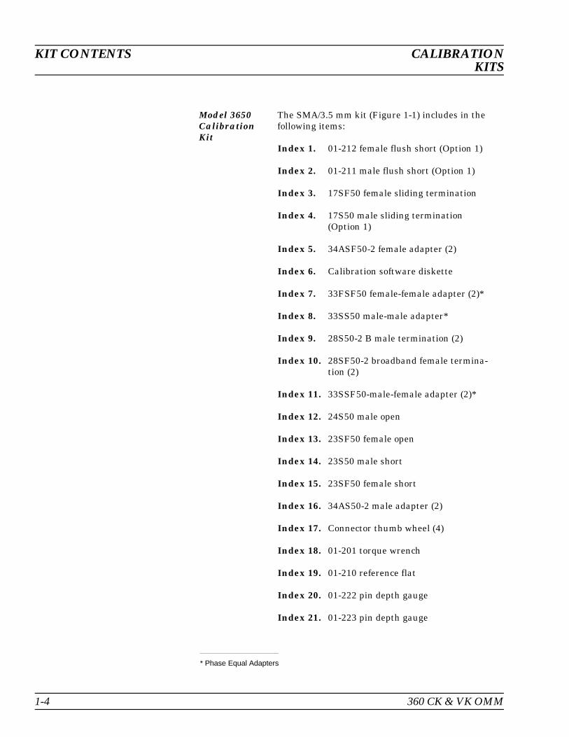
Model 3650CalibrationKit
The SMA/3.5 mm kit (Figure 1-1) includes in thefollowing items:
Index 1. 01-212 female flush short (Option 1)
Index 2. 01-211 male flush short (Option 1)
Index 3. 17SF50 female sliding termination
Index 4. 17S50 male sliding termination(Option 1)
Index 5. 34ASF50-2 female adapter (2)
Index 6. Calibration software diskette
Index 7. 33FSF50 female-female adapter (2)*
Index 8. 33SS50 male-male adapter*
Index 9. 28S50-2 B male termination (2)
Index 10. 28SF50-2 broadband female termina-tion (2)
Index 11. 33SSF50-male-female adapter (2)*
Index 12. 24S50 male open
Index 13. 23SF50 female open
Index 14. 23S50 male short
Index 15. 23SF50 female short
Index 16. 34AS50-2 male adapter (2)
Index 17. Connector thumb wheel (4)
Index 18. 01-201 torque wrench
Index 19. 01-210 reference flat
Index 20. 01-222 pin depth gauge
Index 21. 01-223 pin depth gauge
* Phase Equal Adapters
KIT CONTENTS CALIBRATIONKITS
1-4 360 CK & VK OMM

* Phase Equal Adapters
ANRITSU MODEL 3650
21
22
8
7
6
1918
17 16 13 1215 14 11 9
3
1
2
4
5
10
*
*
*
Figure 1-1. Model 3650 (SMA/3.5 mm) Calibration Kit Components
CALIBRATION KIT CONTENTSKITS
360 CK & VK OMM 1-5

Model 3651CalibrationKit
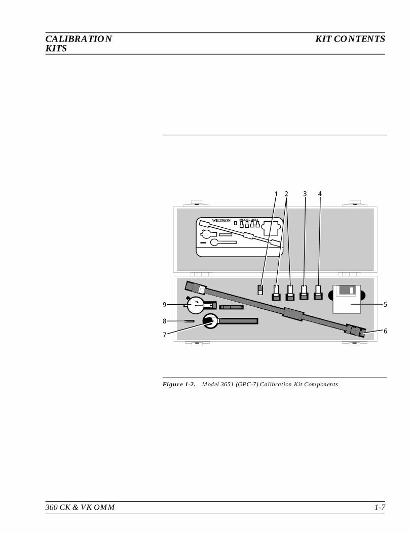
The GPC-7 kit (Figure 1-2) includes in the followingitems:
Index 1. 01-221 collects and extract tools
Index 2. 28A50-2 broadband termination (2)
Index 3. 24A50 open
Index 4. 23A50 short
Index 5. Calibration software diskette
Index 6. 17A50 sliding termination (Option 1)
Index 7. 01-200 torque wrench
Index 8. 01-210 reference flat
Index 9. 01-220 pin depth gauge
KIT CONTENTS CALIBRATIONKITS
1-6 360 CK & VK OMM
WILTRON MODEL 3651
1 2 3 4
5
67
8
9
Figure 1-2. Model 3651 (GPC-7) Calibration Kit Components
CALIBRATION KIT CONTENTSKITS
360 CK & VK OMM 1-7
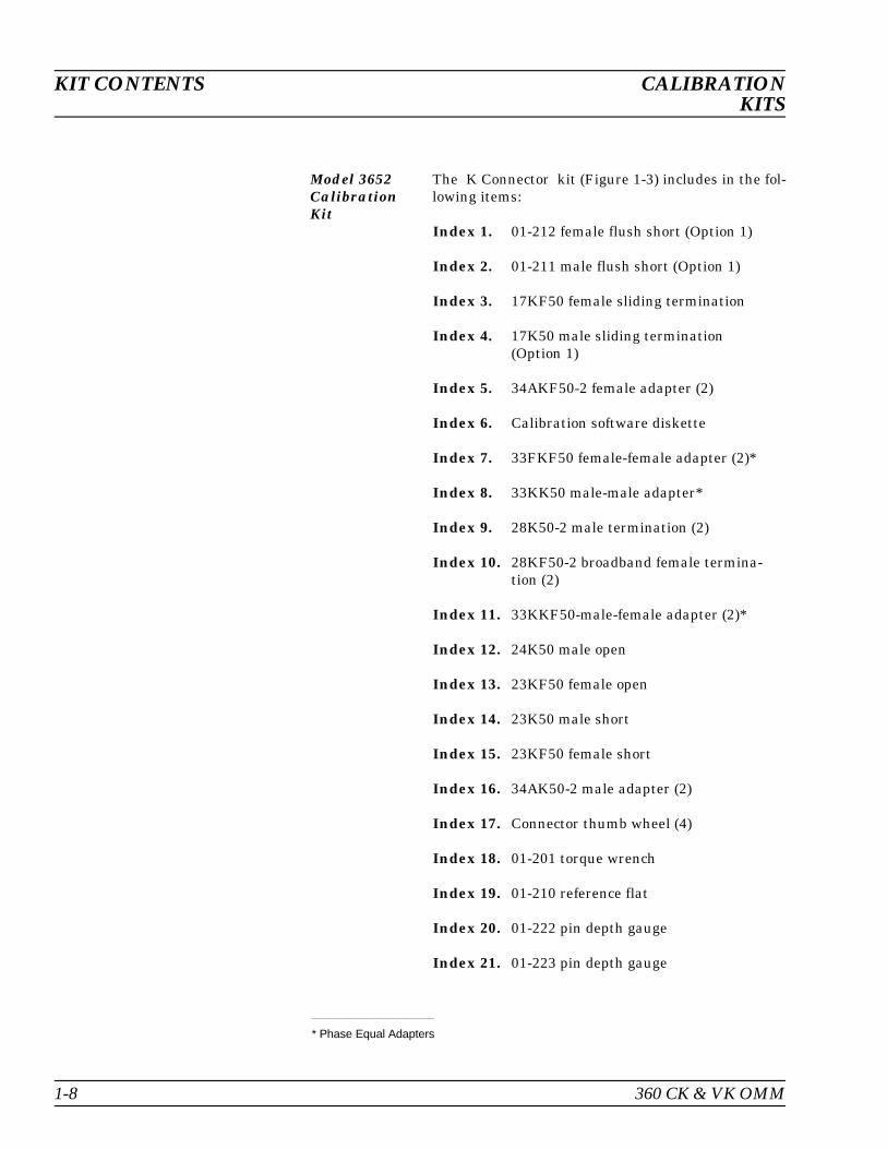
Model 3652CalibrationKit
The K Connector kit (Figure 1-3) includes in the fol-lowing items:
Index 1. 01-212 female flush short (Option 1)
Index 2. 01-211 male flush short (Option 1)
Index 3. 17KF50 female sliding termination
Index 4. 17K50 male sliding termination(Option 1)
Index 5. 34AKF50-2 female adapter (2)
Index 6. Calibration software diskette
Index 7. 33FKF50 female-female adapter (2)*
Index 8. 33KK50 male-male adapter*
Index 9. 28K50-2 male termination (2)
Index 10. 28KF50-2 broadband female termina-tion (2)
Index 11. 33KKF50-male-female adapter (2)*
Index 12. 24K50 male open
Index 13. 23KF50 female open
Index 14. 23K50 male short
Index 15. 23KF50 female short
Index 16. 34AK50-2 male adapter (2)
Index 17. Connector thumb wheel (4)
Index 18. 01-201 torque wrench
Index 19. 01-210 reference flat
Index 20. 01-222 pin depth gauge
Index 21. 01-223 pin depth gauge
* Phase Equal Adapters
KIT CONTENTS CALIBRATIONKITS
1-8 360 CK & VK OMM

*
* Phase Equal Adapters
ANRITSU MODEL 3652
21
22
8
7
6
1918
17 16 13 1215 14 11 9
3
1
2
4
5
10
*
*
*
Figure 1-3. Model 3652 (K Connector) Calibration Kit Components
CALIBRATION KIT CONTENTSKITS
360 CK & VK OMM 1-9

Model 3653CalibrationKit
The Type N kit (Figure 1-4) includes in the followingitems:
Index 1. 28N50-2 broadband male termination (2)
Index 2. 34AN50-2 male adapter (2)
Index 3. Calibration software diskette
Index 4. 34ANF50-2 female adapter (2)
Index 5. 28NF50-2BBraodband female termina-tion (2)
Index 6. 24NF50 female open
Index 7. 24N50 male open
Index 8. 23NF50 female short
Index 9. 23N50 male short
Index 10. 01-213 reference gauge
Index 11. 01-224 pin depth gauge
KIT CONTENTS CALIBRATIONKITS
1-10 360 CK & VK OMM

ANRITSU MODEL 3653
11
10 9 8 7 6 5 4
3
21
Figure 1-4. Model 3653 (Type N) calibration kit Components
CALIBRATION KIT CONTENTSKITS
360 CK & VK OMM 1-11

Model 3654/3654B Cali-bration Kit
The V Connector kit (Figure 1-5) includes in the fol-lowing items:
Index 1. 17VF50B female sliding termination
Index 2. 17V50B male sliding termination
Index 3. 33VVF50 male-female adapter (2)
Index 4. Calibration software, 2360-54B
Index 5. 28V50B male broadband termination (2)
Index 6. 28VF50B female broadband termina-tion (2)
Index 7. 24V50B male open
Index 8. 24VF50B female open
Index 9. 23V50B-5.1 male short 5.1mm
Index 10. 23VF50B-5.1 female short 5.1mm
Index 11. 33VV50 male-male adapter
Index 12. 33VFVF50 female-female adapter (2)
Index 13. Connector thumb wheel (4)
Index 14. 01-201 torque wrench
Index 15. 01-323 female adapter for pin gauge
Index 16. 01-322 pin depth gauge
Index 17. 01-210 reference flat
Index 18. 01-204 adapter wrench
Index 19. 01-312 male flush short
Index 20. 01-311 female flush short
KIT CONTENTS CALIBRATIONKITS
1-12 360 CK & VK OMM

WILTRON MODEL 3654
2019
1817
16
15
14
13 12 11 10 9 8 7 6
5
4
3
21
Figure 1-5. Model 3654 (V Connector) Calibration Kit Components
360 CK & VK OMM 1-13/1-14
CALIBRATION KIT CONTENTSKITS

Table of Contents
2-1 INTRODUCTION . . . . . . . . . . . . . . . . . . 2-3
2-2 PURPOSE . . . . . . . . . . . . . . . . . . . . . . 2-3
2-3 KIT CONTENTS . . . . . . . . . . . . . . . . . . . 2-3
2-4 OPERATION . . . . . . . . . . . . . . . . . . . . . 2-9
2-5 PERFORMANCE VERIFICATION PROCEDURE 2-9
Chapter 2Verification Kits
Chapter 2Verification Kits
2-1 INTRODUCTION This chapter lists the contents of the verification kits and provides op-eration and verification procedures.
NOTEThe components in these kits of the highest quality and ac-curacy. All components are NBS(National Bureau of Stand-ards) traceable, which means that the components are veryaccurate and repeatable. Handle with care.
2-2 PURPOSE The verification kits let you verify the performance of a calibrated vec-tor network analyzer. The components in these kits are based uponstandards that are traceable to the NIST (National Institute of Stand-ards and Technology). They provide the basis for issuing a calibrationcertification label.
2-3 KIT CONTENTS Contents of the calibrations kits are listed on the following pages.
360 CK&VK OMM 2-3
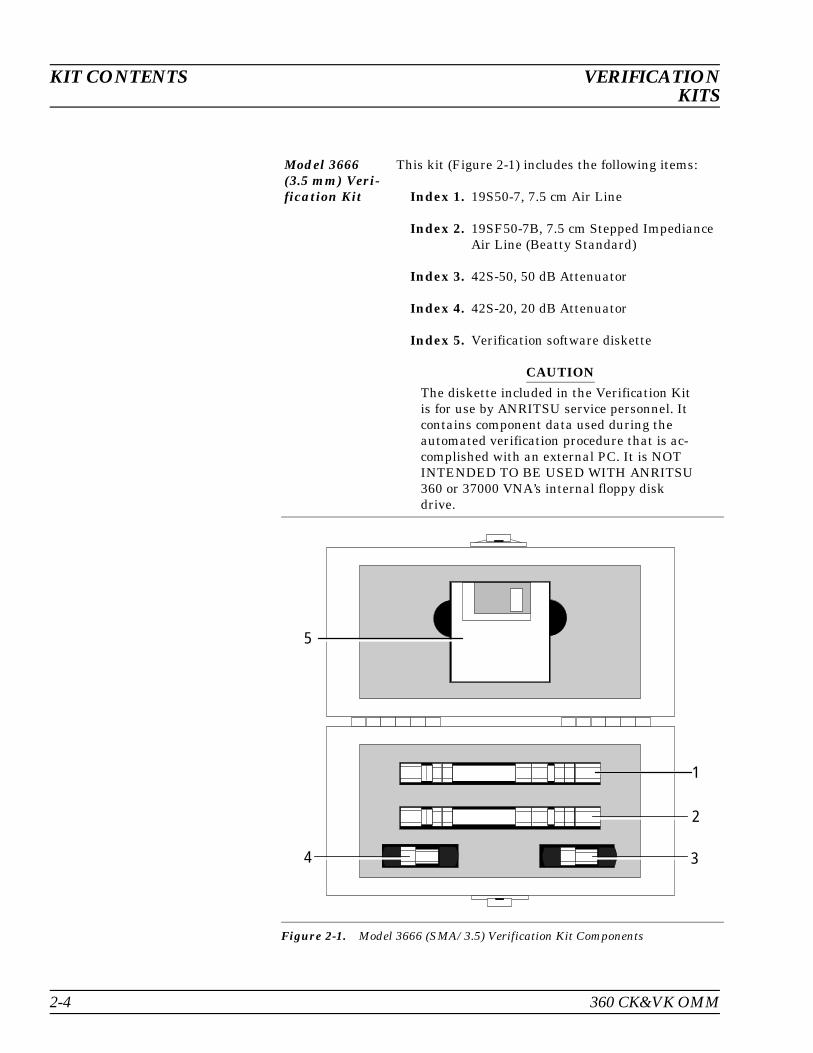
Model 3666(3.5 mm) Veri-fication Kit
This kit (Figure 2-1) includes the following items:
Index 1. 19S50-7, 7.5 cm Air Line
Index 2. 19SF50-7B, 7.5 cm Stepped ImpedianceAir Line (Beatty Standard)
Index 3. 42S-50, 50 dB Attenuator
Index 4. 42S-20, 20 dB Attenuator
Index 5. Verification software diskette
CAUTION
The diskette included in the Verification Kitis for use by ANRITSU service personnel. Itcontains component data used during theautomated verification procedure that is ac-complished with an external PC. It is NOTINTENDED TO BE USED WITH ANRITSU360 or 37000 VNA’s internal floppy diskdrive.
34
5
2
1
Figure 2-1. Model 3666 (SMA/3.5) Verification Kit Components
KIT CONTENTS VERIFICATIONKITS
2-4 360 CK&VK OMM

Model 3667(GPC-7) Veri-fication Kit
This kit (Figure 2-2) includes in the following items:
Index 1. Verification software diskette
Index 2. 42A-50, 50 dB Attenuator
Index 3. 18A50-10, 10 cm Air Line
Index 4. 42A-20, 20 dB Attenuator
Index 5. 18A50-10B, 10 cm Stepped ImpedianceAir Line (Beatty Standard)
CAUTION
The diskette included in the Verification Kitis for use by ANRITSU service personnel. Itcontains component data used during theautomated verification procedure that is ac-complished with an external PC. It is NOTINTENDED TO BE USED WITH ANRITSU360 or 37000 VNA’s internal floppy diskdrive.
3
4
5
2
1
Figure 2-2. Model 3667 (GPC 7) Verification Kit Components
VERIFICATION KIT CONTENTSKITS
360 CK&VK OMM 2-5

Model 3668(K Connec-tor) Verifica-tion Kit
This kit (Figure 2-3) includes the following items:
Index 1. Verification software diskette
Index 2. 19K50-7, 7.5 cm Air Line
Index 3. 42K-50, 50 dB Attenuator
Index 4. 42K-20, 20 dB Attenuator
Index 5. 18K50-7B, 7.5 cm Stepped ImpedianceAir Line (Beatty Standard)
CAUTION
The diskette included in the Verification Kitis for use by ANRITSU service personnel. Itcontains component data used during theautomated verification procedure that is ac-complished with an external PC. It is NOTINTENDED TO BE USED WITH ANRITSU360 or 37000 VNA’s internal floppy diskdrive.
34
5
2
1
Figure 2-3. Model 3668 (K Connector) Verification Kit Components
KIT CONTENTS VERIFICATIONKITS
2-6 360 CK&VK OMM
3
4
5
2
1
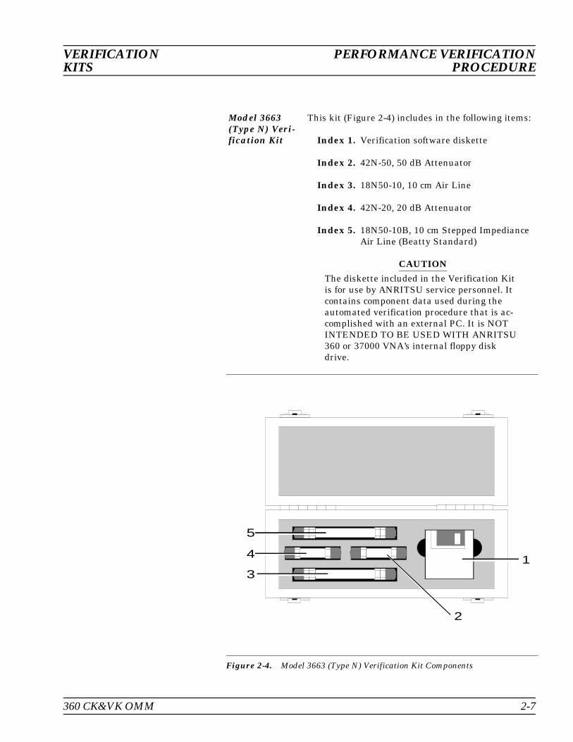
Figure 2-4. Model 3663 (Type N) Verification Kit Components
Model 3663 (Type N) Veri-fication Kit
This kit (Figure 2-4) includes in the following items:
Index 1. Verification software diskette
Index 2. 42N-50, 50 dB Attenuator
Index 3. 18N50-10, 10 cm Air Line
Index 4. 42N-20, 20 dB Attenuator
Index 5. 18N50-10B, 10 cm Stepped ImpedianceAir Line (Beatty Standard)
CAUTION
The diskette included in the Verification Kitis for use by ANRITSU service personnel. Itcontains component data used during theautomated verification procedure that is ac-complished with an external PC. It is NOTINTENDED TO BE USED WITH ANRITSU360 or 37000 VNA’s internal floppy diskdrive.
VERIFICATION PERFORMANCE VERIFICATIONKITS PROCEDURE
360 CK&VK OMM 2-7
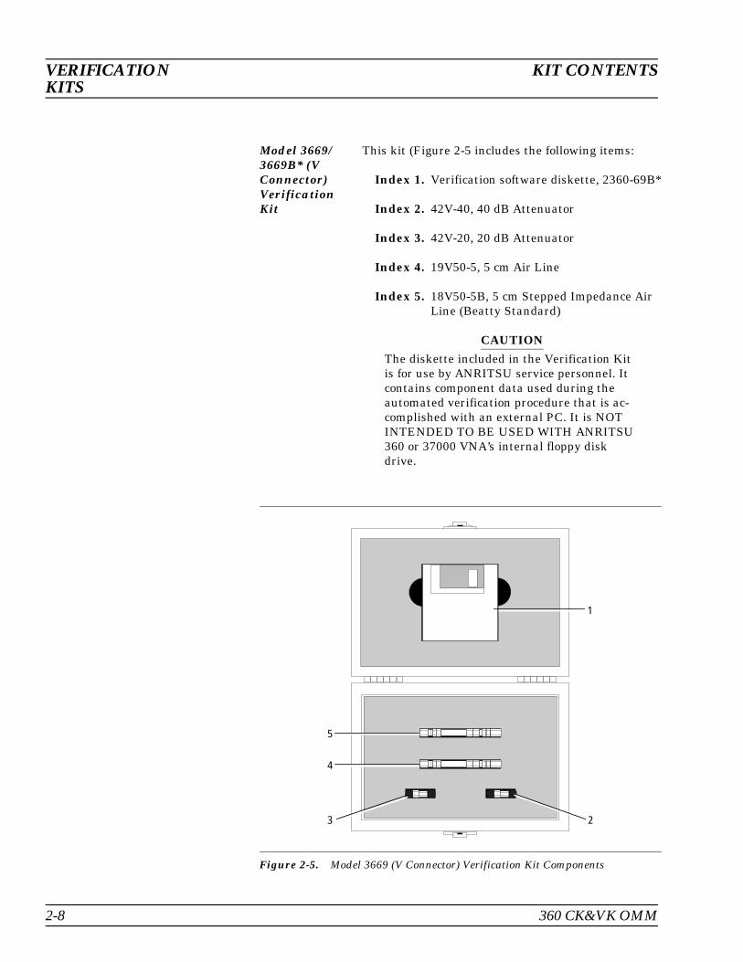
Model 3669/3669B* (VConnector)VerificationKit
This kit (Figure 2-5 includes the following items:
Index 1. Verification software diskette, 2360-69B*
Index 2. 42V-40, 40 dB Attenuator
Index 3. 42V-20, 20 dB Attenuator
Index 4. 19V50-5, 5 cm Air Line
Index 5. 18V50-5B, 5 cm Stepped Impedance AirLine (Beatty Standard)
CAUTION
The diskette included in the Verification Kitis for use by ANRITSU service personnel. Itcontains component data used during theautomated verification procedure that is ac-complished with an external PC. It is NOTINTENDED TO BE USED WITH ANRITSU360 or 37000 VNA’s internal floppy diskdrive.
1
23
4
5
Figure 2-5. Model 3669 (V Connector) Verification Kit Components
VERIFICATION KIT CONTENTSKITS
2-8 360 CK&VK OMM
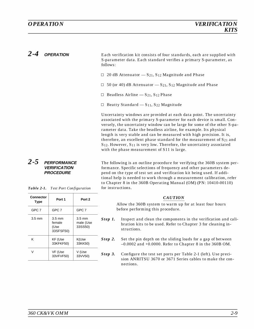
2-4 OPERATION Each verification kit consists of four standards, each are supplied withS-parameter data. Each standard verifies a primary S-parameter, asfollows:
20 dB Attenuator — S21, S12 Magnitude and Phase
50 (or 40) dB Attenuator — S21, S12 Magnitude and Phase
Beadless Airline — S21, S12 Phase
Beatty Standard — S11, S22 Magnitude
Uncertainty windows are provided at each data point. The uncertaintyassociated with the primary S-parameter for each device is small. Con-versely, the uncertainty window can be large for some of the other S-pa-rameter data. Take the beadless airline, for example. Its physicallength is very stable and can be measured with high precision. It is,therefore, an excellent phase standard for the measurement of S21 andS12. However, S11 is very low. Therefore, the uncertainty associatedwith the phase measurement of S11 is large.
2-5 PERFORMANCEVERIFICATIONPROCEDURE
The following is an outline procedure for verifying the 360B system per-formance. Specific selections of frequency and other parameters de-pend on the type of test set and verification kit being used. If addi-tional help is needed to work through a measurement calibration, referto Chapter 8 in the 360B Operating Manual (OM) (PN: 10410-00110)for instructions.
CAUTION
Allow the 360B system to warm up for at least four hoursbefore performing this procedure.
Step 1. Inspect and clean the components in the verification and cali-bration kits to be used. Refer to Chapter 3 for cleaning in-structions.
Step 2. Set the pin depth on the sliding loads for a gap of between–0.0002 and +0.0000. Refer to Chapter 8 in the 360B OM.
Step 3. Configure the test set ports per Table 2-1 (left). Use preci-sion ANRITSU 3670 or 3671 Series cables to make the con-nections.
ConnectorType
Port 1 Port 2
GPC 7 GPC 7 GPC 7
3.5 mm 3.5 mmfemale(Use33SFSF50)
3.5 mmmale (Use33SS50)
K KF (Use33KFKF50)
K(Use33KK50)
V VF (Use33VFVF50)
V (Use33VV50)
Table 2-1. Test Port Configuration
OPERATION VERIFICATIONKITS
360 CK&VK OMM 2-9
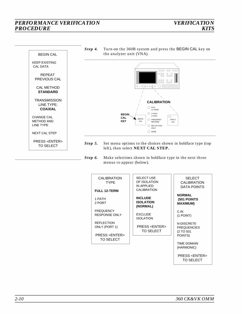
Step 4. Turn-on the 360B system and press the BEGIN CAL key onthe analyzer unit (VNA).
Step 5. Set menu options to the choices shown in boldface type (topleft), then select NEXT CAL STEP.
Step 6. Make selections shown in boldface type in the next threemenus to appear (below).
BEGINCAL
APPLYCAL
BEGINCALKEY
FULL12 TERM
1 PATH2 PORT
FREQUENCYREPONSE
REFLECTIONONLY
NONE
CALIBRATION
BEGIN CAL
KEEP EXISTING CAL DATA
REPEAT PREVIOUS CAL
CAL METHODSTANDARD
TRANSMISSIONLINE TYPE:COAXIAL
CHANGE CAL METHOD ANDLINE TYPE
NEXT CAL STEP
PRESS <ENTER>TO SELECT
CALIBRATION TYPE
FULL 12-TERM
1 PATH2 PORT
FREQUENCYRESPONSE ONLY
REFLECTION ONLY (PORT 1)
PRESS <ENTER> TO SELECT
SELECT USE OF ISOLATIONIN APPLIEDCALIBRATION
INCLUDE ISOLATION (NORMAL)
EXCLUDEISOLATION
PRESS <ENTER> TO SELECT
SELECT CALIBRATION DATA POINTS
NORMAL (501 POINTSMAXIMUM)
C.W. (1 POINT)
N-DISCRETE FREQUENCIES (2 TO 501 POINTS)
TIME DOMAIN (HARMONIC)
PRESS <ENTER> TO SELECT
PERFORMANCE VERIFICATION VERIFICATIONPROCEDURE KITS
2-10 360 CK&VK OMM

Step 7. Enter your start and stop frequencies — based on the testset in use — when the next menu (top left) appears.
Step 8. When the Confirm Calibration Parameters menu (bottomleft) appears, set or confirm test port connectors are correct.
Step 9. Place the cursor next to THROUGH PARAMETERS andpress the ENTER key.
Step 10. Set or check that OFFSET LENGTH is 0.0000 mm whenthe menu (below) appears.
CONFIRMCALIBRATIONPARAMETERS
PORT 1 CONNXXXXXXXXX
PORT 2 CONNXXXXXXXXX
REFLECTIONPAIRINGMIXED
LOAD TYPESLIDING
THROUGHPARAMETERS
REFERENCEIMPEDANCE
TEST SIGNALS
START CAL
PRESS <ENTER>TO SELECTOR CHANGE
MENU C20
ENTERTHROUGH LINEPARAMETERS
OFFSET LENGTHOF THROUGH
OFFSET LENGTH0.0000 mm
LOSS EQUATIONA+B*FREQ^c
A: DC COEFF(dB/m)0.0000
B: FREQ COEFF(dB/m*FREQ^c0.0000 e-6
C: FREQEXPONENT0.500
PRESS <ENTER>WHEN COMPLETE
MENU C2
FREQ RANGE OF CALIBRATION
START XX.XXXX GHz
STOP XX.XXXX GHz
XXX DATA PTS USING ABOVE START AND STOP XX.X MHz STEP SIZE
NEXT CAL STEP
PRESS <ENTER> TO SELECT
VERIFICATION PERFORMANCE VERIFICATIONKITS PROCEDURE
360 CK&VK OMM 2-11

Step 11. Place the cursor next to REFERENCE IMPEDANCE, inthe Confirm Calibration Parameters menu (page 2-10), andpress the ENTER key.
Step 12. Set or check that REFERENCE IMPEDANCE is correctfor your device (default is 50Ω), when the menu (top left) ap-pears.
Step 13. Place the cursor next to TEST SIGNALS, in the ConfirmCalibration Parameters menu (page 2-10), and press the EN-TER key.
Step 14. Set or check that SOURCE 1 POWER is set to the maximumvalue for your instrument, and verify that all step attenu-ators are set to 0 dB.
Step 15. When you have made all of the choices in the Confirm Cali-bration Parmeters menu (page 2-10), select START CALand follow the promts that appear on the VNA display.
ENTER REFIMPEDANCE
REFERENCEIMPEDANCE XX.XXX Ω
PRESS <ENTER> WHEN COMPLETE
REDUCEDTEST SIGNALS
SOURCE 1 PWRXX.X dBm
SOURCE 2 PWRX.X dBm
PORT 1 SOURCEX0 dB (0-70)
PORT 1 TESTX0 dB (0-00)
PORT 2 SOURCEX0 dB (0-70)
PORT 2 TESTX0 dB (0-40)
FLAT TESTPORT POWER
PREVIOUS MENU
PRESS <ENTER>TO SELECT
PERFORMANCE VERIFICATION VERIFICATIONPROCEDURE KITS
2-12 360 CK&VK OMM

Step 16. Press the CHANNEL MENU key (below) and select ALLFOUR CHANNELS from the menu (left) that appears.
CHANNELS
CHANNEL MENU KEY
CH2
CHANNELMENU
CH1
CH3 CH4
SELECTDISPLAY MODE
SINGLECHANNEL
DUALCHANNELS 1 – 3
OVERLAY DUALCHANNELS 1 – 3
DUALCHANNELS 2 – 4
OVERLAY DUALCHANNELS 2 – 4
ALL FOURCHANNELS
PRESS <ENTER>TO SELECT
VERIFICATION PERFORMANCE VERIFICATIONKITS PROCEDURE
360 CK&VK OMM 2-13

Step 17. Press the GRAPH TYPE (below) key, and select the appropri-ate LOG MAGNITUDE AND PHASE or LINEAR MAG-NITUDE AND PHASE from the available menus (left).
DISPLAY
GRAPH TYPE KEY
TRACEMEMORY
SPARAMS
SETSCALE
REFPOS
GRAPHTYPE
AUTOSCALE
SELECTGRAPH TYPE
LOGMAGNITUDE
PHASE
LOG MAGNITUDEAND PHASE
SMITH CHART(IMPEDANCES)
SWR
GROUP DELAY
MORE
PRESS <ENTER>TO SELECT
SELECTGRAPH TYPE
SINGLECHANNEL
ADMITTANCESMITH CHART
LINEAR POLAR
LOG POLAR
LINEAR MAGAND PHASE
REAL
IMAGINARY
REAL AND IMAGINARY
MORE
PRESS <ENTER>TO SELECT
PERFORMANCE VERIFICATION VERIFICATIONPROCEDURE KITS
2-14 360 CK&VK OMM

Step 18. Press the AVG/SMOOTH MENU key (below), and enter 128(512 for 50 dB attenuator).
Step 19. Measure and obtain a tabular-data printout of all four S-pa-rameters for each device in the verification kit. (See Figure 2-5 for tips on using the beadless airline.)
Step 20. Compare the measured data with the data provided with theverification kit. Verify that each measured point falls withinthe uncertainty window of the appropriate verification datapoint.
AVG/SMOOTHKEY
NORMAL
REDUCED
MINIMUM
TRACESMOOTH
AVG/SMOOTH
MENUAVERAGE
ENHANCEMENT
OPTIONMENU
VIDEOIF BW
DATAENHANCEMENT
AVERAGING128 MEAS.PER POINT
VERIFICATION PERFORMANCE VERIFICATIONKITS PROCEDURE
360 CK&VK OMM 2-15
PORT 1 PORT 2
LABELLETTERING
Black Dot
CENTERCONDUCTOR
OUTERCONDUCTOR
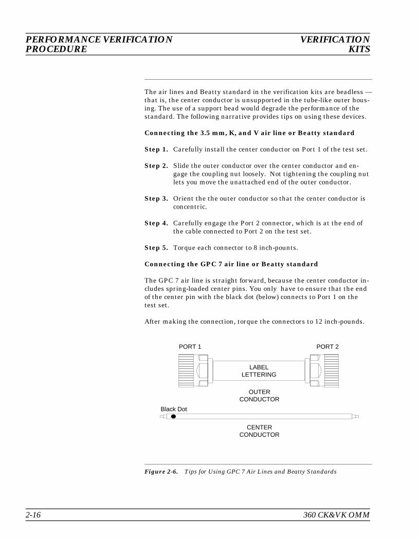
The air lines and Beatty standard in the verification kits are beadless —that is, the center conductor is unsupported in the tube-like outer hous-ing. The use of a support bead would degrade the performance of thestandard. The following narrative provides tips on using these devices.
Connecting the 3.5 mm, K, and V air line or Beatty standard
Step 1. Carefully install the center conductor on Port 1 of the test set.
Step 2. Slide the outer conductor over the center conductor and en-gage the coupling nut loosely. Not tightening the coupling nutlets you move the unattached end of the outer conductor.
Step 3. Orient the the outer conductor so that the center conductor isconcentric.
Step 4. Carefully engage the Port 2 connector, which is at the end ofthe cable connected to Port 2 on the test set.
Step 5. Torque each connector to 8 inch-pounts.
Connecting the GPC 7 air line or Beatty standard
The GPC 7 air line is straight forward, because the center conductor in-cludes spring-loaded center pins. You only have to ensure that the endof the center pin with the black dot (below) connects to Port 1 on thetest set.
After making the connection, torque the connectors to 12 inch-pounds.
Figure 2-6. Tips for Using GPC 7 Air Lines and Beatty Standards
PERFORMANCE VERIFICATION VERIFICATIONPROCEDURE KITS
2-16 360 CK&VK OMM
Table of Contents
3-1 INTRODUCTION . . . . . . . . . . . . . . . . . . 3-3
3-2 PRECAUTIONS FOR USING CONNECTORS . . . . . . . . . . . . . . . . . . . 3-3
3-3 CLEANING INSTRUCTIONS . . . . . . . . . . . 3-6
Chapter 3Maintenance Instructions
Chapter 3Maintenance Instructions
3-1 INTRODUCTION This chapter provides instructions and discussion on the care and useof precision connectors.
3-2 PRECAUTIONS FORUSING CONNECTORS
The following are precautionary notes related to the use of connectors.For specific information on setting pin depths on sliding terminations,refer to the 360B Operation Manual, Chapter 8.
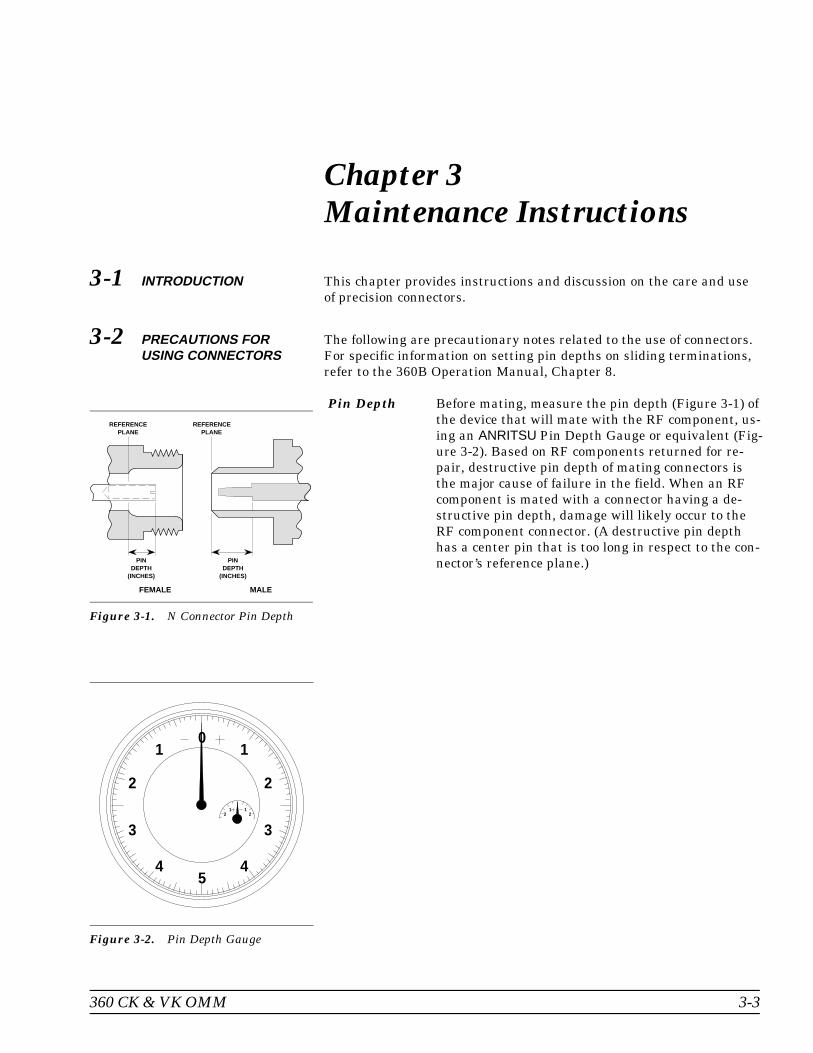
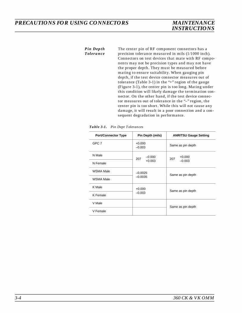
Pin Depth Before mating, measure the pin depth (Figure 3-1) ofthe device that will mate with the RF component, us-ing an ANRITSU Pin Depth Gauge or equivalent (Fig-ure 3-2). Based on RF components returned for re-pair, destructive pin depth of mating connectors isthe major cause of failure in the field. When an RFcomponent is mated with a connector having a de-structive pin depth, damage will likely occur to theRF component connector. (A destructive pin depthhas a center pin that is too long in respect to the con-nector’s reference plane.)
REFERENCEPLANE
MALE
PINDEPTH
(INCHES)
REFERENCEPLANE
FEMALE
PINDEPTH
(INCHES)
Figure 3-1. N Connector Pin Depth
01
2
3
45
1
2
3
4
21 1
2
Figure 3-2. Pin Depth Gauge
360 CK & VK OMM 3-3
Pin DepthTolerance
The center pin of RF component connectors has aprecision tolerance measured in mils (1/1000 inch).Connectors on test devices that mate with RF compo-nents may not be precision types and may not havethe proper depth. They must be measured beforemating to ensure suitability. When gauging pindepth, if the test device connector measures out oftolerance (Table 3-1) in the “+” region of the gauge(Figure 3-1), the center pin is too long. Mating underthis condition will likely damage the termination con-nector. On the other hand, if the test device connec-tor measures out of tolerance in the “–” region, thecenter pin is too short. While this will not cause anydamage, it will result in a poor connection and a con-sequent degradation in performance.
Port/Connector Type Pin Depth (mils) ANRITSU Gauge Setting
GPC 7 +0.000–0.003
Same as pin depth
N Male207
–0.000+0.003
207+0.000–0.003
N Female
WSMA Male –0.0025–0.0035
Same as pin depthWSMA Male
K Male +0.000–0.003
Same as pin depthK Female
V MaleSame as pin depth
V Female
Table 3-1. Pin Dept Tolerances
PRECAUTIONS FOR USING CONNECTORS MAINTENANCEINSTRUCTIONS
3-4 360 CK & VK OMM

Over TorquingConnectors
Over torquing connectors is destructive; it may dam-age the connector center pin. Finger-tight is usuallysufficient, especially on Type N connectors. Neveruse pliers to tighten connectors.
Teflon Tun-ing Washers
The center conductor on most RF components con-tains a small teflon tuning washer located near thepoint of mating (interface). This washer compen-sates for minor impedance discontinuities at the in-terface. The washer’s location is critical to the RFcomponent’s performance. Do not disturb it.
MechanicalShock
RF components are designed to withstand years ofnormal bench handling. However, do not drop or oth-erwise treat them roughly. They are laboratory-qual-ity devices, and like other such devices, they requirecareful handling.
MAINTENANCE PRECAUTIONS FOR USING CONNECTORS INSTRUCTIONS
360 CK & VK OMM 3-5
3-3 CLEANINGINSTRUCTIONS
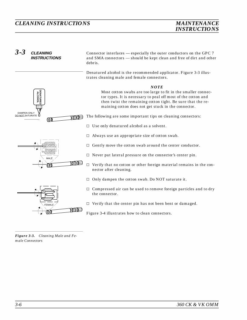
Connector interfaces — especially the outer conductors on the GPC 7and SMA connectors — should be kept clean and free of dirt and otherdebris.
Denatured alcohol is the recommended applicator. Figure 3-3 illus-trates cleaning male and female connectors.
NOTEMost cotton swabs are too large to fit in the smaller connec-tor types. It is necessary to peal off most of the cotton andthen twist the remaining cotton tight. Be sure that the re-maining cotton does not get stuck in the connector.
The following are some important tips on cleaning connectors:
Use only denatured alcohol as a solvent.
Always use an appropriate size of cotton swab.
Gently move the cotton swab around the center conductor.
Never put lateral pressure on the connector’s center pin.
Verify that no cotton or other foreign material remains in the con-nector after cleaning.
Only dampen the cotton swab. Do NOT saturate it.
Compressed air can be used to remove foreign particles and to drythe connector.
Verify that the center pin has not been bent or damaged.
Figure 3-4 illustrates how to clean connectors.
DE
NA
TU
RE
DA
LCO
HO
L
DAMPEN ONLYDO NOT SATURATE
MALE
FEMALE
Figure 3-3. Cleaning Male and Fe-male Connectors
CLEANING INSTRUCTIONS MAINTENANCEINSTRUCTIONS
3-6 360 CK & VK OMM
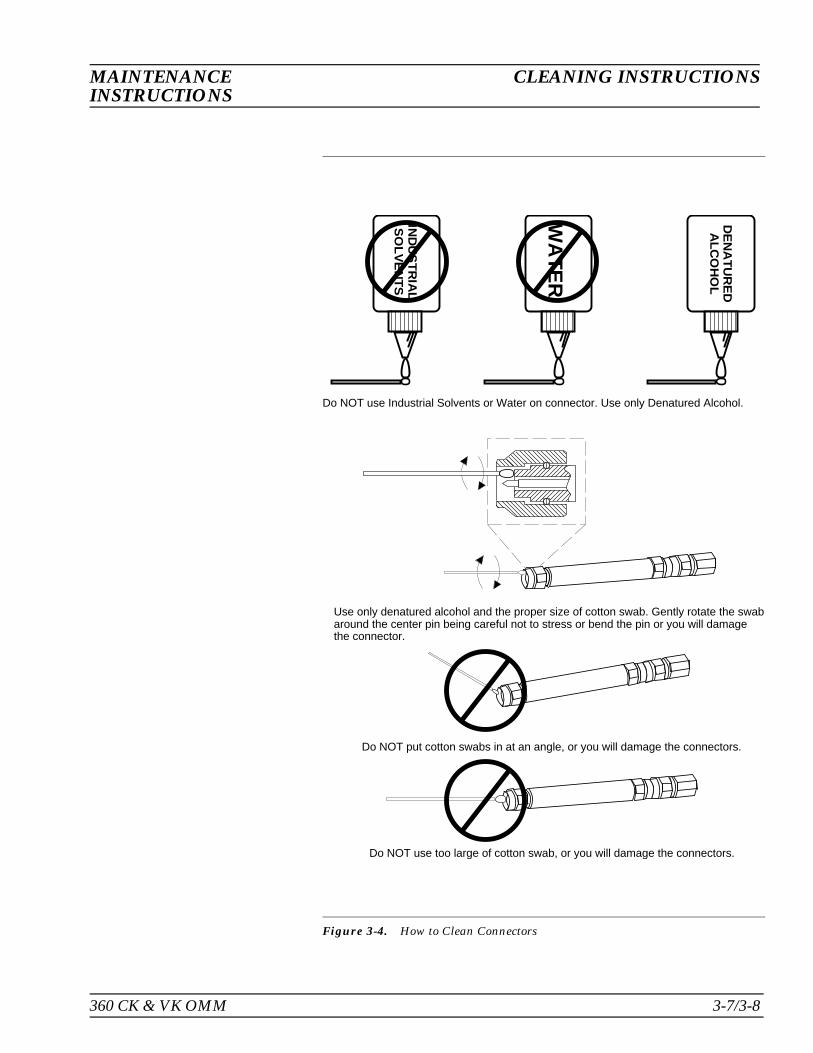
Do NOT use Industrial Solvents or Water on connector. Use only Denatured Alcohol.
Use only denatured alcohol and the proper size of cotton swab. Gently rotate the swabaround the center pin being careful not to stress or bend the pin or you will damagethe connector.
Do NOT put cotton swabs in at an angle, or you will damage the connectors.
Do NOT use too large of cotton swab, or you will damage the connectors.
DE
NA
TU
RE
DA
LCO
HO
L
WA
TE
R
IND
US
TR
IAL
SO
LVE
NT
S
Figure 3-4. How to Clean Connectors
360 CK & VK OMM 3-7/3-8
MAINTENANCE CLEANING INSTRUCTIONSINSTRUCTIONS