Embed Size (px)
Citation preview

Model 360/361 Control Valves
Dyna-Flo Control Valve Services Ltd. Phone: 780 • 469 • 4000 Toll Free: 1 • 866 • 396 • 2356 Fax: 780 • 469 • 4035 Website: www.dynafl o.com
P-360M0917B 1
Operation, Parts, and Instruction Manual
TABLE OF CONTENTS
General 2 Lapping 13
Scope 2 Assembly 15
Specifi cations 3 Stud Installation 15
Unpacking 5 Plug Seal Assembly 15
Installation 5 Trim Parts Assembly 19
Air Piping 6 Bonnet Installation 20
Periodic Inspection 7 Packing Installation 21
Actuator Removal 7 Globe Valve Cross Section - Figure 32 26
Maintenance 8 Angle Valve Cross Section - Figure 34 28
Packing Maintenance 8 Body to Bonnet Stud Torque - Table 5 30
Disassembly 9 Packing Nut Torque - Table 6 30
Packing Removal 9 Valve Stem Connection Information - Table 7 30
Bonnet Removal 9 Parts 31
Trim Parts Removal 11 Model Builder 49
Packing Parts Removal 11
Plug Seal Removal 12
Figure 1 360 ControlValve & DFC Actuator

Dyna-Flo Control Valve Services Ltd. Phone: 780 • 469 • 4000 Toll Free: 1 • 866 • 396 • 2356 Fax: 780 • 469 • 4035 Website: www.dynafl o.com
Model 360/361 Control Valves
P-360M0917B 2
Operation, Parts, and Instruction Manual
NOTICE These instructions are meant to be used with the Dyna-Flo 360/361 Technical Bulletin as they refer to Figures and Tables therein. If you do not have the Technical Bulletin, contact Dyna-Flo immediately, or visit www.dynafl o.com
Each control valve is factory checked. Check the calibration for the specifi c application, before a valve is put into service.
It is the intention of this document to provide users with an accurate guide for safe installation and maintenance of the 360/361 Control Valves. Revisions are available at above mentioned website.
GENERALThe following instructions are to be thoroughly reviewed and understood prior to installing, operating or performing maintenance on this equipment. Work on this equipment should be performed by experienced personnel. Throughout the manual, safety and caution notes appear and must be strictly followed, to prevent serious injury or equipment malfunction.
SCOPEThe control valve confi guration and construction materials were selected to meet particular pressure, temperature, and process conditions. Some material combinations are limited in their pressure and temperature ranges. Do not apply any other conditions to the valve without fi rst contacting your Dyna-Flo sales offi ce.
This manual is written to be a practical and useful guide to maintaining the Dyna-Flo 360 Control Valve.
SAFETY CAUTION Only well trained experienced technicians should perform these procedures. Use safe work practices and lock out procedures when isolating valves and actuators. It is also important to wear the proper protective equipment when performing any installation or maintenance activity. Use only parts and materials rated for the process being used, operating conditions, and environmental conditions products will be used in.
To avoid personal injury or installation damage as a result of the sudden release of process pressure or damage to equipment, do not install the valve assembly where service conditions could exceed the limits stated in this manual, sales bulletin or on the equipment nameplates. Use government codes, accepted industry standards and good piping practices, and select proper pressure-relieving equipment for protection of your installation. Always be aware of fl ammable process and instrument gas.
Always be aware of the hazards of actuators, especially spring-loaded actuators. Be sure that the actuator is de-energized or in the failed position before performing any maintenance procedure.
These valves have dangerous pinch points. Never put your hands inside the valve unless you are certain that the plug and stem will not move.

Model 360/361 Control Valves
Dyna-Flo Control Valve Services Ltd. Phone: 780 • 469 • 4000 Toll Free: 1 • 866 • 396 • 2356 Fax: 780 • 469 • 4035 Website: www.dynafl o.com
P-360M0917B 3
Operation, Parts, and Instruction Manual
SPECIFICATIONS
Confi gurations The Model 360 control valve is a high capacity single port, globe style valve with a bolted type bonnet. The standard valve plug action is push down to close. Refer to Table 1.
PTFE Seat and Metal Seat Available.
Consult your Dyna-Flo sales offi ce for other available confi gurations.
Sizes and Connection Styles (Refer to Table 1) Model: 360
Size: 1”, 1-1/2”, 2”, 3”, 4”, 6”, 8”
Body: Globe (All Sizes), Angle (1” / 2” / 3” / 4” / 6”)
Rating: ASME 150 / 300 / 600
Connection: RF / RTJ / BWE - All Sizes SWE / NPT - 1”, 1-1/2”, and 2”
Maximum Inlet Pressures and Temperatures Flanged valves consistent with ASME Class 150, 300, and 600 rating as per ASME B16.34, unless limited.
Maximum Pressure Drops Maximum pressure drop is the same as maximum inlet pressure unless restricted by the following:
Standard Valve Trim: Figure 10 of the Sales Bulletin.
Anti-Cavitation Trim: Figure 10 of the Sales Bulletin.
Low-Noise Valve Trim: Figure 10 of the Sales Bulletin.
Characteristic and Flow Direction • Equal Percentage (Standard) - Flow Down
• Quick Opening - Flow Down
• Linear - Flow Down
• Low-Noise 3 (Linear) - Flow Up
• Anti-Cavitation 1-Stage (Linear) - Flow Down
• Anti-Cavitation 2-Stage (Linear) - Flow Down
Dimensions Valve and Actuator Outline Dimension Diagram Refer to Figure 2 of the Sales Bulletin.
Valve and Actuator Assembly Dimensions Refer to Tables 8 to 19 of the Sales Bulletin.
Approximate Valve Body and Actuator Weights Refer to Table 4.
Materials Body and bonnet material options include:
LCC (A350 LF2/A105 Dual Grade optional bonnet material)
WCC (A350 LF2/A105 Dual Grade optional bonnet material)
WC9 (A182 F22 optional bonnet material)
CF8M (A182 F316 optional bonnet material)
Refer to Figure 10 of the Sales Bulletin for valve construction material temperature limitations. Refer to Table 23 of the Sales Bulletin for trim selections.
Cross-Section of the Model 360 Control Valves Refer to Figures 32 to 37.
Port Diameters and Maximum Valve Plug Travel Refer to Tables 4 to 6 of the Sales Bulletin.
Packing Type and Examples The Standard packing is PTFE V-ring. Live-loaded low emission, graphite, KALREZ® and other packing arrangements are available. Refer to Figures 27, 29, 30, & 31.
Maximum Valve Sizing Coeffi cients For standard coeffi cients at maximum travel, refer to Table 27 & 28 of the Sales Bulletin. For full list of coeffi cients refer to document P-CVSM.
Service Application
Refer to Tables 20 - 26 of the Sales Bulletin.
For more information and other options contact your Dyna-Flo sales offi ce.

Dyna-Flo Control Valve Services Ltd. Phone: 780 • 469 • 4000 Toll Free: 1 • 866 • 396 • 2356 Fax: 780 • 469 • 4035 Website: www.dynafl o.com
Model 360/361 Control Valves
P-360M0917B 4
Operation, Parts, and Instruction Manual
Table 2
Standard Shut-Off Classifi cations (in accordance with ANSI/FCI 70.2 and IEC 60534-4)
Valve Trim Seat Option Shut-Off Class
All(Except Anti-Cavitation)
PTFE (Soft Seated)
Standard Class V (Air Test)
OptionalClass V
Class VI(1)
Metal
Standard Class IV
OptionalClass V(2)
Class VI(1)
Anti-Cavitation 1 Stage Metal Standard Class IV
Optional Class V
Anti-Cavitation 2 Stage Metal Standard Class V
Notes:1 - Refer to Table 3.
2 - Class V shut-off requires a spring-loaded seal ring, radius-seat plug, and wide-bevel seat ring. Not available with 8 inch ports or quick opening cages.
Table 1
Available Valve Confi gurations
Valve Model Valve SizeInch
End Connection
NPT(1)RF(2) and RTJ(3) (Flanged)
BWE(4) SWE(5)
ASME Class 150 ASME Class 300 ASME Class 600
3601 / 1-1/2 / 2
3 / 4 / 6 / 8
360A1 & 2
3 / 4 / 6
Notes:
1 - NPT = Screwed.
2 - RF = Raised Face.
3 - RTJ = Ring Type Joint.
4 - BWE = Butt Weld (ASME Class 600 Only).
5 - SWE = Socket Weld (ASME Class 600 Only).
Table 3
Available Valve Confi gurations for Class VI Shut-Off (in accordance with ANSI / FCI 70.2)
Valve Model Port SizeInch Valve Seat Minimum Seat Load
360Refer to Table 23 for Trim
≥3.4375≤7 Metal(1) 300 lbs./lineal inch
≥3.4375≤7 PTFE Consult Dyna-Flo
Note: 1 - Class VI shut-off requires a spring-loaded seal ring, radius-seat plug, and wide-bevel seat ring.

Model 360/361 Control Valves
Dyna-Flo Control Valve Services Ltd. Phone: 780 • 469 • 4000 Toll Free: 1 • 866 • 396 • 2356 Fax: 780 • 469 • 4035 Website: www.dynafl o.com
P-360M0917B 5
Operation, Parts, and Instruction Manual
UNPACKING VALVE FROM SHIPPING CONTAINERSpecial Tools Required:
• Properly Rated Lifting Straps (2 – 4 Straps) refer to Table 4 for actuator weights.
• Lifting Device (Example: Crane)
Check the packing list, verify that the list includes all the materials in the shipping container before unpacking. Valve information can be found on the nameplate (Key 47). Refer toFigure 2 for nameplate location.
When lifting the valve from shipping container, place properly rated lifting straps securely around the neck of the actuator, refer to Figure 2 for strap placement. Straps should be placed to avoid damage to tubing and other mounted accessories.
For valve assemblies without an attached actuator, use caution when lifting or positioning straps so as not to damage the valve stem.
Lift the valve/actuator assembly using proper lifting techniques.
INSTALLATIONBefore You Begin:
• Read the General and Scope section of this manual (Page 2).
• Read Safety Caution (Page 2).
• Sudden movement of actuator can cause damage or injury. It helps to have the actuator de-energized.
• Use safe work practices and lock out procedures before placing valve in-line.
NOTE: For butt weld valve bodies, depending on the body material, post-weld heat treatment might be required. Soft parts, seals, some metal trim, threading and shrink-fi t parts can be damaged by post-weld heat treatment. If post-weld heat treatment is required, it is recommended that all internal valve parts be removed from the valve body. Contact Dyna-Flo for more information.
Parts Required:
• Appropriate Line Flange Nuts and Bolts
• Appropriate Line Flange Gaskets
• If the valve has small internal fl ow passages such as Anti-Cavitation or Low-Noise trim, the installation of an upstream strainer should be considered to prevent clogging of these small passages.
Figure 2 Actuator Lifting Suggestions
Installation Steps:
1 Check the packing box bolting (Key 38) for proper tightness. Refer to Packing Installation on Page 20 for proper packing tightening instructions.
2 The valve assembly may be installed in any position unless limited by vibration considerations, it is however recommended that the valve be installed with the valve stem (Key 5) perpendicular to the ground. NOTE: For some non-vertical orientations, the valve actuator may need to be supported.
3 Install the valve with fl ow through the valve in the direction shown by the fl ow arrow on the valve body.
4 Install the appropriate line fl ange gaskets.
5 Apply Permatex® Nickel Anti-Seize to the threads of the fl ange studs and install.
6 When possible, before tightening the line bolting, stroke the valve and check for smooth operation through the full stroke. Unsteady valve stem movement could be an indication of an internal problem.
7 Tighten the line fl ange bolting in even increments in a crisscross pattern until the correct line bolt torque specifi cation is reached.
LIFTING STRAP
47

Dyna-Flo Control Valve Services Ltd. Phone: 780 • 469 • 4000 Toll Free: 1 • 866 • 396 • 2356 Fax: 780 • 469 • 4035 Website: www.dynafl o.com
Model 360/361 Control Valves
P-360M0917B 6
Operation, Parts, and Instruction Manual
INSTALLATION (Continued)
AIR PIPINGWARNING: Property damage, environmental harm, and personal injury can result from the use of supply gas other than clean, non-corrosive, oil and moisture free air. Do not exceed the supply pressure indicated on the serial plate located on the actuator.
Before You Begin:
Note: Standard actuators accept ¼” (6 mm) NPT connections.
• Refer to the appropriate actuator instruction manual when necessary.
Piping Installation Steps:
1 Use 3/8” (outside diameter) tubing (or equivalent) for air lines.
2 Install the required line vents, valves, drains, seals, and fi lters to the actuator.
Table 4
Valve Body / Actuator Confi gurations and Approximate Weights
Valve Size(inch)
Body Onlylb (Kg)
With Fail OpenActuator Size
Valve and ActuatorAssembly Weight
lb (Kg)With Fail CloseActuator Size
Valve and ActuatorAssembly Weight
lb (Kg)
1 30 (14) DFO - 1046 66 (30) DFC - 1046 64 (29)
DFO - 1069 70 (32) DFC - 1069 78 (26)
1-1/2 45 (20)DFO - 1046 81 (37) DFC - 1046 79 (36)
DFO - 1069 85 (39) DFC - 1069 93 (42)
2 85 (39)DFO - 2069 136 (62) DFC - 2069 135 (61)
DFO - 2105 167 (76) DFC - 2105 175 (79)
3 125 (57)DFO - 2069 176 (80) DFC - 2069 175 (79)
DFO - 2105 207 (94) DFC - 2105 215 (98)
4 170 (77)DFO - 2105 252 (114) DFC - 2105 260 (118)
DFO - 2156 277 (126) DFC - 2156 291 (132)
6 350 (159)DFO - 3156 466 (211) DFC - 3156 471 (214)
DFO - 3220 585 (266) DFC - 3220 604 (274)
8 900 (408) DFO - 3220 1135 (515) DFC - 3220 1154 (523)
Model 360/361 Control Valves
Dyna-Flo Control Valve Services Ltd. Phone: 780 • 469 • 4000 Toll Free: 1 • 866 • 396 • 2356 Fax: 780 • 469 • 4035 Website: www.dynafl o.com
P-360M0917B 7
Operation, Parts, and Instruction Manual
PERIODIC INSPECTION
Special Equipment Required:
• Bypass or block valves.
Before You Begin:
• Read Safety Caution (Page 2).
• Use safe work practices and lock out procedures.
• Disconnect supply lines (air or gas), electric power, or control signal to the actuator. Sudden movement of actuator can cause damage or injury, make sure actuator will not operate.
• Vent any pneumatic actuator loading pressure and relieve any actuator spring preload if present.
• Relieve process pressure and drain the process fl uid from up and down stream of valve.
• Be aware of potentially hazardous process material that may be present in-line and in-valve. Isolate the valve from process pressure. Use a bypass or block valve if necessary, or completely shut off the process.
Inspection Steps:
1 Check for visible signs of leakage around all seal and gasket areas.
2 Check the valve for damage, especially damage caused by corrosive fumes or process drippings.
3 Clean and repaint the areas as required.
4 Ensure all accessories, mounting brackets, and fasteners are secure.
5 Clean any dirt and foreign material from the valve stem (Key 5).
ACTUATOR REMOVALNote: Actuator removal does not require that the valve be removed from the pipeline.
Tools Needed:
• Properly Rated Lifting Straps or Chains
• Lifting Device (Example: Crane)
• Hammer and Blunted Chisel
Before You Begin:
• Read Safety Caution (Page 2).
• Use safe work practices and lock out procedures.
• Disconnect supply lines (air or gas), electric power, or control signal to the actuator. Sudden movement of actuator can cause damage or injury, make sure actuator will not operate.
• Vent any pneumatic actuator loading pressure and relieve any actuator spring preload if present.
1 Refer to the appropriate actuator instruction manual for more information regarding the actuator being removed.
2 If the valve has been removed from the pipeline, place the valve assembly on a fl at work surface that can support the weight.
3 Before the actuator is removed, support the actuator using lifting hooks or straps rated to support the weight of the actuator.
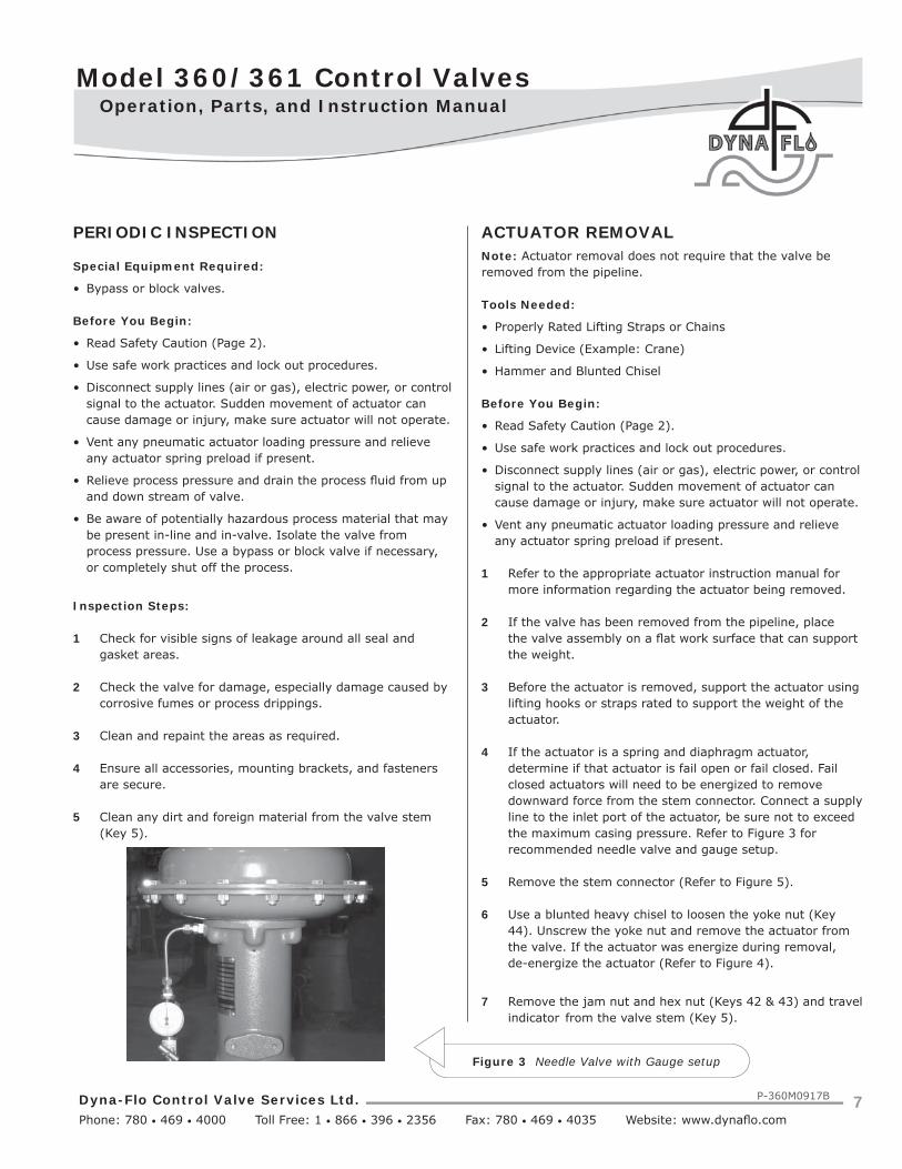
4 If the actuator is a spring and diaphragm actuator, determine if that actuator is fail open or fail closed. Fail closed actuators will need to be energized to remove downward force from the stem connector. Connect a supply line to the inlet port of the actuator, be sure not to exceed the maximum casing pressure. Refer to Figure 3 for recommended needle valve and gauge setup.
5 Remove the stem connector (Refer to Figure 5).
6 Use a blunted heavy chisel to loosen the yoke nut (Key 44). Unscrew the yoke nut and remove the actuator from the valve. If the actuator was energize during removal, de-energize the actuator (Refer to Figure 4).
7 Remove the jam nut and hex nut (Keys 42 & 43) and travel indicator from the valve stem (Key 5).
Figure 3 Needle Valve with Gauge setup

Dyna-Flo Control Valve Services Ltd. Phone: 780 • 469 • 4000 Toll Free: 1 • 866 • 396 • 2356 Fax: 780 • 469 • 4035 Website: www.dynafl o.com
Model 360/361 Control Valves
P-360M0917B 8
Operation, Parts, and Instruction Manual
MAINTENANCENote: Seals, soft parts, and packing (including live loaded packing) should all be inspected frequently for leaks, wear and damage. Maintenance to the valve can be performed while the valve is still in-line, the actuator must be removed to replace packing (Refer to Page 6 for Actuator Removal instructions).
Before you begin:
• Read Safety Caution (Page 2).
• Determine if valve has standard or live loaded packing (Refer to Figures 27, 29, 30 & 31).
• Follow Steps 1 – 6 of Before You Begin from PERIODIC INSPECTION (Page 7).
Packing MaintenanceIf the packing is leaking, proper tightening of the packing may correct the leak. If re-tightening the packing to the proper specifi cations does not stop the leakage it is possible that the stem or wall of the packing box is damaged. Replace or repair parts as necessary. For instructions on packing removal only, refer to the Disassembly, Packing Removal section on Page 9.
1 Determine the type of packing installed in the valve. Refer to Figures 27, 29, 30, and 31 for packing styles.
Figure 4 Yoke Nut being loosened with a Chisel
For Single PTFE V-Ring Packing (Spring-Loaded):
Tighten the packing nuts (Key 38) evenly in an alternating pattern until the shoulder of the packing follower (Key 35) makes contact with the top face of the bonnet (Key 26). Proceed to tighten the packing nuts to the torque specifi cation listed in Table 6. Refer to Figure 27.
For Double PTFE V-Ring and Graphite Packing:
Tighten the packing nuts (Key 38) evenly in an alternating pattern to the minimum recommended torque specifi cations listed in Table 6 on Page 30, continue tightening until leakage stops or the maximum torque specifi cation is reached. If leakage continues after reaching the maximum recommended torque the packing will need to be replaced, do not tighten the packing past the maximum recommended torque as this will cause excessive packing friction.
For Live-Loaded Packing:
Refer to the Sliding Stem Live-Loaded Packing Manual (P-LLPS) for proper maintenance procedures.
Figure 5 Packing Nut and Stem Connector Detail
4445
38
STEM CONNECTOR
42
43

Model 360/361 Control Valves
Dyna-Flo Control Valve Services Ltd. Phone: 780 • 469 • 4000 Toll Free: 1 • 866 • 396 • 2356 Fax: 780 • 469 • 4035 Website: www.dynafl o.com
P-360M0917B 9
Operation, Parts, and Instruction Manual
DISASSEMBLYBefore You Begin:
• Read Safety Caution (Page 2).
• Use safe work practices and lock out procedures.
• Remove the actuator from the valve (Refer to Actuator Removal Instructions, Page 7).
• Relieve process pressure and drain the process fl uid from up and down stream of valve.
• Be aware of potentially hazardous process material that may be present in-line and in-valve. Isolate the valve from process pressure. Use a bypass or block valve if necessary, or completely shut off the process.
• For Angle Body Valves refer to Figure 34.
PACKING REMOVALFor Live Loaded Packing refer to Figure 31 and the Live Loaded Sliding Stem Packing Manual (P-LLPS).
Special Tools Required:
• Mechanics Pick Set
NOTE: Packing box parts are easier to remove after the bonnet (Key 26) has been separated from the valve body (Key 1) and the valve stem (Key 5) has been removed. If the packing is all that needs to be removed, it is possible to extract packing box parts carefully using a mechanics pick set.
WARNING: Process medium and pressure may become stored in the packing, use caution when removing packing parts.
1 Remove the packing nuts (Key 38).
2 Remove the upper wiper (Key 36) if present, graphite packing does not include an upper wiper.
3 Remove the packing follower (Key 35).
4 It is recommended to proceed to the Bonnet Removal section to continue with valve disassembly. If the packing is all that needs to be removed, remove the contents of the packing box (Keys 30, 31, 32, 33, & 34) using a mechanics pick set being careful not to damage the valve stem (Key 5) or wall of the packing box of the bonnet (Key 26). For packing reassembly refer to Packing Installation section (Page 21).
Figure 6 Packing Removal (Steps 1 - 3)
BONNET REMOVALWARNING: Process medium and pressure may be trapped inside the valve body (Key 1). Use caution when removing the valve bonnet (Key 26). Refer to Safety Caution on Page 2.
1 Loosen the bonnet nuts (Key 28) 1 full turn after the contact between the nuts and the top surface of the bonnet (Key 26) has been broken. Do not remove the bonnet nuts until any trapped process pressure has been vented. Refer to Figure 7.
2 Break the contact between the valve body (Key 1) and the bonnet (Key 26), use a pry bar or blunt chisel to help with the separation if necessary.
38
35
37
36
29
26
5

Dyna-Flo Control Valve Services Ltd. Phone: 780 • 469 • 4000 Toll Free: 1 • 866 • 396 • 2356 Fax: 780 • 469 • 4035 Website: www.dynafl o.com
Model 360/361 Control Valves
P-360M0917B 10
Operation, Parts, and Instruction Manual
DISASSEMBLY (Continued)BONNET REMOVAL (Continued)3 If no process fl uid or gas escapes from the body-to-bonnet joint proceed by completely removing the bonnet nuts (Key 28). Refer to Figure 8.
4 Carefully lift the bonnet (Key 26) from the valve body (Key 1), be sure that the valve stem (Key 5) and plug (Key 3) assembly do not drop from the bonnet and get damaged. Also, if the valve plug and stem assembly begin to lift when lifting the bonnet, it may be necessary to gently tap the stem from the bonnet using a rubber mallet as the bonnet is being lifted.
5 The bonnet gasket (Key 22) may stick to the bonnet during removal. Remove the bonnet gasket.
Figure 7 Bonnet Removal (Steps 1 - 2)
Figure 8 Bonnet Removal (Steps 3 - 4)
28
26
29
22
5
2
1
28
26
STEP 1
CHISEL

Model 360/361 Control Valves
Dyna-Flo Control Valve Services Ltd. Phone: 780 • 469 • 4000 Toll Free: 1 • 866 • 396 • 2356 Fax: 780 • 469 • 4035 Website: www.dynafl o.com
P-360M0917B 11
Operation, Parts, and Instruction Manual
Figure 9 Standard Trim Parts Removal (Steps 1 - 6)
DISASSEMBLY (Continued)TRIM PARTS REMOVALFor Reduced Trim:
A Remove the cage adapter ring (Key 24). Refer to Figure 36. NOTE: 6x4 inch valve do not use a cage adapter.
B Remove the cage adapter gasket (Key 25), metal shim (Key 21), and spiral wound gasket (Key 20).
For 8 inch valve assemblies:
A Remove the load ring (Key 23). Refer to Figure 37.
1 Remove the metal shim (Key 21) and spiral wound gasket (Key 20) if they haven’t already been removed. Refer to Figure 9.
2 Remove the valve stem (Key 5) / valve plug (Key 3) assembly from the valve body (Key 1), refer to Figure 9. Refer to Plug Seal Removal section for disassembly instructions.
3 Carefully remove the cage (Key 19).
4 Remove the seat ring (Key 15) and seat ring gasket (Key 12). For Soft Seat valves: Remove the disk retainer (Key 18), PTFE disk (Key 17), disk seat (Key 16), and seat ring gasket (Key 12). Refer to Figure 37.
5 For Reduced Trim: Remove the seat ring adapter (Key 13) and seat ring adapter gasket (Key 14). Refer to Figure 36. NOTE: 6x4 inch valves do not use a seat ring adapter.
6 Clean and inspect all parts for damage, especially gasket seal surfaces. Replace all damaged parts and gaskets with new parts as necessary, gaskets cannot be reused.
PACKING PARTS REMOVALWARNING: Compressed gasses could be trapped between packing rings.
NOTE: For Live Loaded Packing refer to Figure 31 and the LiveLoaded Sliding Stem Packing Manual (P-LLPS).
1 Using a blunt or rounded tool or rod, carefully tap the packing parts (Keys 30, 31, 32, 33, and 34) out of the packing bore of the bonnet (Key 26). A mechanic’s pick set can also be used to pull packing parts from the bore. For other packing arrangements, refer to Figures 29 to 31.
PLUG / STEMASSEMBLY
5
3
20
19
12
21
2
1
15

Dyna-Flo Control Valve Services Ltd. Phone: 780 • 469 • 4000 Toll Free: 1 • 866 • 396 • 2356 Fax: 780 • 469 • 4035 Website: www.dynafl o.com
Model 360/361 Control Valves
P-360M0917B 12
Operation, Parts, and Instruction Manual
PLUG SEAL REMOVALFor Model 360 Two-Piece Plug Seal Ring Assemblies:
1 Carefully remove the seal ring (Key 7) from the plug groove, a pick set or fl at screw driver may be required. Refer to Figure 11.
2 Carefully remove the backup ring (Key 6) from the plug groove, a pick set or fl at screw driver may be required.
Figure 10 Packing Parts Removal (Step 1)
DISASSEMBLY (Continued)PACKING PARTS REMOVAL (Continued)2 Clean and inspect the bonnet for damage, pay particular attention to the packing bore surface and the gasket sealing surface. Replace or repair the bonnet as necessary. Metal packing parts can be reused if they are not damaged, all other packing parts should be replaced.
Figure 11 Two-Piece Plug Seal Ring Removal (Model 360)
For Model 360 Three-Piece Seal Ring Assemblies:
NOTE: 8 inch valve assemblies have only one-piece plug seals, they only use a seal ring (Key 8).
1 Carefully remove the retaining ring (Key 10) from the plug groove, a pick set or fl at screw driver may be required. Refer to Figure 12.
2 Remove the backup ring (Key 9).
3 Remove the seal ring (Key 8).
BLUNT ROD
26
5
7
6
3

Model 360/361 Control Valves
Dyna-Flo Control Valve Services Ltd. Phone: 780 • 469 • 4000 Toll Free: 1 • 866 • 396 • 2356 Fax: 780 • 469 • 4035 Website: www.dynafl o.com
P-360M0917B 13
Operation, Parts, and Instruction Manual
DISASSEMBLY (Continued)PLUG SEAL REMOVAL (Continued)For Model 360 Three-Piece Plug Seal Ring Assemblies with Anti-Extrusion Rings:
1 Carefully remove the retaining ring (Key 10) from the plug, a pick set or fl at screw driver may be required to pry the spiral rings of the retaining ring apart to assist removal. Refer to Figure 12.
2 Remove the backup ring (Key 9).
3 Remove the anti-extrusion ring (Key 11). The anti- extrusion ring is only included in valve assemblies rated for over 450°F (232°C).
4 Remove the seal ring (Key 8).
For Model 361 Valves (Refer to Figure 13):
1 Remove the piston rings (Key 48). NOTE: Piston rings are broken in half and can be easily pulled apart.
Figure 12Three-Piece Plug Seal Removal (Model 360 Only)
For All Models:
Clean and inspect all parts for damage, especially the stem (Key 5) and plug (Key 3) surfaces. Minor scratches can be buffed or lapped out, major scratches (scratches that will stop a fi nger nail) will need to be machined or replaced. Replace all damaged parts and soft parts with new parts.
Figure 13 Model 361 Piston Ring Removal
LAPPINGExpect a certain amount of leakage in valves with metal seats. In some cases where leakage has become excessive, lapping can improve sealing performance. Before performing the lapping process, insure all trim parts have been thoroughly cleaned and are free of debris. Do not lap soft seat valves.
NOTE: Spiral wound gaskets (Key 20) make their seal by being crushed and cannot be reused, this includes gaskets required to be used during the lapping process. It may be desirable to use an already crushed gasket in the lapping process to be replaced with new gaskets during reassembly.
CAUTION: Once lapping has been performed with a previously crushed gasket, it is important to mark the position and alignment of all trim parts (Keys 3, 15, and 19) before removal and reassembly. If trim parts are reassembled out of their lapped alignment excessive leakage may result.
10
9
8
3
5
11**Only included in valveassemblies rated over 450°F (232°C).
5
48
3

Dyna-Flo Control Valve Services Ltd. Phone: 780 • 469 • 4000 Toll Free: 1 • 866 • 396 • 2356 Fax: 780 • 469 • 4035 Website: www.dynafl o.com
Model 360/361 Control Valves
P-360M0917B 14
Operation, Parts, and Instruction Manual
LAPPING (Continued)Special Tools Required:
• Soft felt marker
• Two wrenches that will slide over the valve stem (Key 5)
• 400 – 600 grit (fi ne grit) Loctite® Clover® compound (Key D)
Lapping Procedure
1 Install the used seat ring gasket (Key 12) into the valve body (Key 1).
2 Install the seat ring (Key 15). Mark the position of seat ring using the marker.
3 Install the cage (Key 19). Mark the position of cage using the marker.
4 Do not install any plug seals into the valve plug (Key 3). Apply fi ne grit Clover® compound to the seating surface of the valve plug. Install the valve plug / stem assembly (Keys 3, 4, 5) into the valve. Mark the position of the plug / stem assembly using the marker.
5 Install used bonnet gaskets (Keys 20, 21, & 22).
6 Carefully lift the bonnet (Key 26) into place and secure the bonnet using half of the bonnet nuts (Key 28). Mark the position of the valve plug (Key 3) on the bonnet (Key 26) using the marker.
7 Install the packing follower (Key 35).
8 Install the jam nut (Key 42) on to the valve stem (Key 5) and build a handle as shown in Figure 14 and 16 using the two wrenches and the hex nut (Key 43).
9 Rotate the valve plug (Key 3) back and forth about a quarter of a full rotation (only a small amount of movement is required, do not make full rotations) over the seat ring (Key 15) using the wrench handles.
10 If a seat leak test is to be performed after lapping to test valve shut off, disassemble the lapping setup after a few cycles of back and forth plug movement. Replace the used gaskets (Keys 12, 20, 21, & 22) with new gaskets and reassemble the valve for testing. NOTE: Another set of new gaskets will need to be used for the fi nal valve assembly if the lapping procedure needs to be repeated after seat leak testing.
Figure 14 Lapping Procedure Setup (Steps 1 - 8)
Figure 15 Lapping Compound Application
4235
26
5
43
282
120 193
1215
WRENCHWRENCH
5
3
APPLY FINE GRIT CLOVER® COMPOUND(KEY D) TO THE SEATING SURFACE OF THE PLUG

Model 360/361 Control Valves
Dyna-Flo Control Valve Services Ltd. Phone: 780 • 469 • 4000 Toll Free: 1 • 866 • 396 • 2356 Fax: 780 • 469 • 4035 Website: www.dynafl o.com
P-360M0917B 15
Operation, Parts, and Instruction Manual
Figure 16 Lapping Procedure Setup (Steps 8 - 10)
STUD INSTALLATION
1 If the studs (Key 2) were replaced, removed, or never installed, apply nickel anti-seize (Key A) to the threads of the end of the stud without a material stamp.
2 Thread the studs (Key 2) into the valve body (Key 1) nickel anti-seize coated end fi rst, until they are completely threaded into the valve body.
PLUG SEAL ASSEMBLY
For Model 360 Two-Piece Plug Seal Ring Assemblies:
Note: Two-piece seals are not available for 8 inch valves.
1 Apply white Molykote® 111 (Key B) to the surface of the backup ring (Key 6).
2 Carefully slide the backup ring (Key 6) over the top of the valve plug (Key 3) and into the groove. Refer to Figure 17.
3 Apply Lubriplate® No. 105 (Key C) to the seal ring (Key 7). Carefully slide the seal ring over the top edge of the valve plug (Key 3) and into the groove, refer to Figure 17.
4 Allow time for the seal ring (Key 7) to shrink back to its original size after installation.
5 Before installing the plug/stem assembly into the valve, apply Lubriplate® No. 105 (Key C) to the outside surface of the plug (Key 3) as shown in Figure 17.
For Model 360 Three-Piece Plug Seal Ring Assemblies:
1 Apply Lubriplate® No. 105 (Key C) to the surface of the seal ring (Key 8).
2 Install the seal ring (Key 8) onto the valve plug (Key 3), refer to Figure 18 for proper seal ring orientation. NOTE: 8 inch valves are technically one-piece plug seals, 8 inch valve assemblies use a seal ring only and do not make use of a backup ring (Key 9) or retaining ring (Key 10).
4 Apply Lubriplate® No. 105 (Key C) to the backup ring (Key 9) and install the backup ring onto the valve plug (Key 3).
5 Apply Lubriplate® No. 105 (Key C) to the retaining ring (Key 10) and install the retaining ring into the retaining ring groove on the valve plug (Key 3).
6 Allow time for the seal ring material to shrink back to its original size after being stretched over the valve plug before installing the plug assembly into the cage (Key 19).
ASSEMBLYBefore You Begin:
• Read Safety Caution (Page 2).
• Use safe work practices and lock out procedures.
• Clean and inspect all parts.
• Replace or repair damaged parts. Replace all soft parts (Seals, o-rings, gaskets, live loaded packing).
Lubricants Required:
• Permatex® Nickel Anti-Seize or equivalent (Key A)
• Dow Corning Molykote® 111 or equivalent (Key B)
• Lubriplate® No. 105 Grease or equivalent (Key C)
43
42
28
1
26
2
2935
5
WRENCHWRENCH

Dyna-Flo Control Valve Services Ltd. Phone: 780 • 469 • 4000 Toll Free: 1 • 866 • 396 • 2356 Fax: 780 • 469 • 4035 Website: www.dynafl o.com
Model 360/361 Control Valves
P-360M0917B 16
Operation, Parts, and Instruction Manual
Figure 17 Two-Piece Plug Seal Assembly (Model 360 Only)
Figure 18 Three-Piece Plug Seal Assembly (Model 360 Only)
10C
9C
8C
3C
9
10
8
SPRING-LOADED SEAL RINGFOR FLOW DOWN VALVES - THE “CUP” OF THE SEAL RING (KEY 8) FACES DOWN.
SPRING-LOADED SEAL RINGFOR FLOW UP VALVES - THE “CUP”OF THE SEAL RING (KEY 8) FACES UP.
NOTE: APPLY GREASE TO ENTIRE OUTSIDE SURFACE OFPLUG.
SPRING-LOADED SEAL RINGFOR BI-DIRECTIONAL VALVES - THE “CUP” OF THE SEAL RINGS (KEY 8) FACE EACH OTHER.
9
9
5
5
7 C
6 B
3 3C
NOTE: APPLY GREASE TO ENTIRE OUTSIDE SURFACE OF PLUG BEFORE INSTALLATION.
6
7
Model 360/361 Control Valves
Dyna-Flo Control Valve Services Ltd. Phone: 780 • 469 • 4000 Toll Free: 1 • 866 • 396 • 2356 Fax: 780 • 469 • 4035 Website: www.dynafl o.com
P-360M0917B 17
Operation, Parts, and Instruction Manual
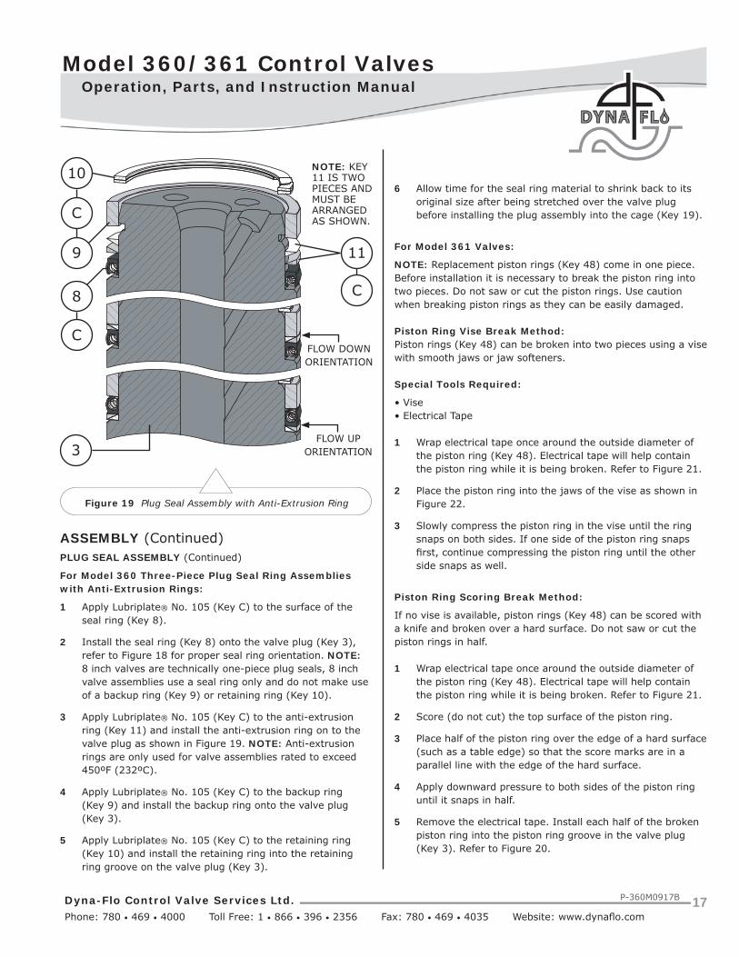
Figure 19 Plug Seal Assembly with Anti-Extrusion Ring
ASSEMBLY (Continued)PLUG SEAL ASSEMBLY (Continued)
For Model 360 Three-Piece Plug Seal Ring Assemblies with Anti-Extrusion Rings:
1 Apply Lubriplate® No. 105 (Key C) to the surface of the seal ring (Key 8).
2 Install the seal ring (Key 8) onto the valve plug (Key 3), refer to Figure 18 for proper seal ring orientation. NOTE: 8 inch valves are technically one-piece plug seals, 8 inch valve assemblies use a seal ring only and do not make use of a backup ring (Key 9) or retaining ring (Key 10).
3 Apply Lubriplate® No. 105 (Key C) to the anti-extrusion ring (Key 11) and install the anti-extrusion ring on to the valve plug as shown in Figure 19. NOTE: Anti-extrusion rings are only used for valve assemblies rated to exceed 450ºF (232ºC).
4 Apply Lubriplate® No. 105 (Key C) to the backup ring (Key 9) and install the backup ring onto the valve plug (Key 3).
5 Apply Lubriplate® No. 105 (Key C) to the retaining ring (Key 10) and install the retaining ring into the retaining ring groove on the valve plug (Key 3).
6 Allow time for the seal ring material to shrink back to its original size after being stretched over the valve plug before installing the plug assembly into the cage (Key 19).
For Model 361 Valves:
NOTE: Replacement piston rings (Key 48) come in one piece. Before installation it is necessary to break the piston ring into two pieces. Do not saw or cut the piston rings. Use caution when breaking piston rings as they can be easily damaged.
Piston Ring Vise Break Method:Piston rings (Key 48) can be broken into two pieces using a vise with smooth jaws or jaw softeners.
Special Tools Required:
• Vise• Electrical Tape
1 Wrap electrical tape once around the outside diameter of the piston ring (Key 48). Electrical tape will help contain the piston ring while it is being broken. Refer to Figure 21.
2 Place the piston ring into the jaws of the vise as shown in Figure 22.
3 Slowly compress the piston ring in the vise until the ring snaps on both sides. If one side of the piston ring snaps fi rst, continue compressing the piston ring until the other side snaps as well.
Piston Ring Scoring Break Method:
If no vise is available, piston rings (Key 48) can be scored with a knife and broken over a hard surface. Do not saw or cut the piston rings in half.
1 Wrap electrical tape once around the outside diameter of the piston ring (Key 48). Electrical tape will help contain the piston ring while it is being broken. Refer to Figure 21.
2 Score (do not cut) the top surface of the piston ring.
3 Place half of the piston ring over the edge of a hard surface (such as a table edge) so that the score marks are in a parallel line with the edge of the hard surface.
4 Apply downward pressure to both sides of the piston ring until it snaps in half.
5 Remove the electrical tape. Install each half of the broken piston ring into the piston ring groove in the valve plug (Key 3). Refer to Figure 20.
10
C
9
C
11
C
8
3
NOTE: KEY11 IS TWOPIECES ANDMUST BE ARRANGED AS SHOWN.
FLOW DOWNORIENTATION
FLOW UPORIENTATION

Dyna-Flo Control Valve Services Ltd. Phone: 780 • 469 • 4000 Toll Free: 1 • 866 • 396 • 2356 Fax: 780 • 469 • 4035 Website: www.dynafl o.com
Model 360/361 Control Valves
P-360M0917B 18
Operation, Parts, and Instruction Manual
Figure 21 Model 361 Piston Ring Vise Break Method (Step 1) Figure 22 Model 361 Piston Ring Vise Break Method (Step 2)
Figure 20 Model 361 Piston Ring Installation
NOTE: APPLY GREASE TO ENTIRE OUTSIDE SURFACE OF PLUG.
485
C
3NOTE: STAGGER THE BREAKS IN THE PISTON RINGS.

Model 360/361 Control Valves
Dyna-Flo Control Valve Services Ltd. Phone: 780 • 469 • 4000 Toll Free: 1 • 866 • 396 • 2356 Fax: 780 • 469 • 4035 Website: www.dynafl o.com
P-360M0917B 19
Operation, Parts, and Instruction Manual
ASSEMBLY (Continued)TRIM PARTS ASSEMBLY
NOTE: Spiral wound gaskets (Keys 20) make their seal by being crushed and cannot be reused.
1 Apply nickel anti-seize (Key A) to the seat ring pocket of the valve body (Key 1) and top surface of the seat ring gasket (Key 12). Install the seat ring gasket into the valve body (Key 1). Refer to Figure 23.
2 For Reduced Trim: Install the seat ring adapter (Key 13) into the valve body. Apply nickel anti-seize (Key A) to the top of the seat ring adapter and top of the second seat ring gasket (Key 14) and install it onto the seat ring adapter. Refer to Figure 36. NOTE: 6x4 inch reduced trim does not use a seat ring adapter, 6x4 inch valves have a special seat ring (Key 15).
3 Install the seat ring (Key 15) into the valve body (Key 1). Refer to Figure 34 for Angle Body valve assemblies.
For Soft Seat Valves: Install the disk seat (Key 16) onto the seat ring gasket (Key 12). Install the PTFE disk (Key 17) onto the disk seat. Install the disk retainer (Key 18) onto the PTFE disk. Refer to Figure 36.
4 Install the cage (Key 19).
5 Apply Lubriplate® No. 105 (Key C) to the side of the valve plug (Key 3) (Refer to Figures 17, 18, & 20). Install the valve plug assembly into the cage (Key 19) (Refer to Figure 23).
6 Apply nickel anti-seize (Key A) to the gasket surface of the cage (Key 19) and top surface of the spiral wound gasket (Key 20), metal shim (Key 21), and bonnet gasket (Key 22). Install the gaskets and shim as shown in Figure 23.
For 8 Inch Valves: Apply nickel anti-seize (Key A) to the gasket seating surface of the valve body (Key 1) and top surface of the bonnet gasket (Key 22) and install. Install the load ring (Key 23). Refer to Figure 37.
7 For Reduced Trim: Install the cage adapter (Key 24). Apply nickel anti-seize (Key A) to the top of the cage adapter and top surface of the cage adapter gasket (Key 25) and install. Refer to Figure 36. NOTE: 6x4 inch reduced trim does not use a cage adapter, 6x4 inch valves have a special cage (Key 19).
Figure 23 Trim Parts Assembly
BONNET INSTALLATION
Before You Begin:
• Read Safety Caution (Page 2).
• Clean and inspect all parts.
• Replace or repair damaged parts. Replace all soft parts (Seals, o-rings, gaskets, live loaded packing).
A 22
21 A
A 20
A
A
15
192
5
73
12 A
1

Dyna-Flo Control Valve Services Ltd. Phone: 780 • 469 • 4000 Toll Free: 1 • 866 • 396 • 2356 Fax: 780 • 469 • 4035 Website: www.dynafl o.com
Model 360/361 Control Valves
P-360M0917B 20
Operation, Parts, and Instruction Manual
ASSEMBLY (Continued)BONNET INSTALLATION (Continued)
1 Apply nickel anti-seize (Key A) to the gasket sealing surface of the valve bonnet (Key 26).
2 Lift and lower the valve bonnet (Key 26) into place over the valve stem (Key 5). Be careful not to damage either the stem, bonnet, or valve body (Key 1).
3 Apply nickel anti-seize (Key A) to the threads of the bonnet studs (Key 2). Thread the bonnet nuts (Key 28) onto the bonnet studs until hand tight.
4 Stroke the valve a few times to center the valve trim.
5 It may help to install the packing follower (Key 22) during bonnet installation to act as a visual cue to indicate areas of over or under tightening. If the packing follower begins to bind or appear lop-sided, this is an indication that torquing procedures in Steps 6 & 7 need to be altered to correct areas that need more tightening or less. The packing follower should remain centered during the torquing process.
6 Follow proper body-to-bonnet bolting procedures. Begin to torque the bonnet nuts (Key 28) ¼ (25%) of the torque value listed in Table 5, torque the nuts in a crisscross pattern as shown in Figure 25. Hot torquing the valve nuts is not recommended.
7 Continue tightening the bonnet nuts (Key 28), increasing the torque by ¼ (25%) of the fi nal torque specifi cation each round of tightening while repeating the crisscross pattern until the fi nal torque specifi cation is reached.
8 Double check the tightness of all nuts by torquing the nuts to the fi nal torque specifi cation one more time after the fi nal torque value was reached.
Figure 24 Bonnet Installation
1
2
3
4
1
2
3
4 5
61
2
3 4
5
67
8
Figure 25 Bolt Tightening Pattern Diagram
SAMPLE BOLT CONFIGURATION
2 A
5
2826
1

Model 360/361 Control Valves
Dyna-Flo Control Valve Services Ltd. Phone: 780 • 469 • 4000 Toll Free: 1 • 866 • 396 • 2356 Fax: 780 • 469 • 4035 Website: www.dynafl o.com
P-360M0917B 21
Operation, Parts, and Instruction Manual
Figure 26 Proper Packing Ring Installation
ASSEMBLY (Continued)PACKING INSTALLATION
For Live Loaded packing instructions see the Live Loaded Sliding Stem Packing Manual (Part Number P-LLPS). For other packing arrangements refer to Figures 27, 29, 30, & 31.
Lubricants Required:
• Permatex® Nickel Anti-Seize or equivalent (Key A)
• Dow Corning Molykote® 111 or equivalent (Key B)
• Lubriplate® No. 105 Grease or equivalent (Key C)
NOTE: To prevent trapping air between packing during installation, it is recommended that packing rings be installed one at a time using the packing follower (Key 35) to push the packing rings in place. Do not force packing rings below the chamfer of the packing bore before adding another ring, packing rings should only be pushed down the thickness of the added ring. Refer to Figure 26.
1 If the packing studs (Key 29) were replaced, removed, or never installed, apply nickel anti-seize (Key A) to the threads of the end of the stud without a material stamp.
2 Thread the studs (Key 29) into the valve bonnet (Key 26) anti-seize coated end fi rst until they are completely threaded into the bonnet.
For Single Style (Spring-Loaded) Packing:
1 Apply Molykote® 111 (Key B) to the lower stem wiper (Key 30). Insert the lower stem wiper into the packing box ring (Key 31). Insert the packing box ring into the packing bore of the valve bonnet (Key 26).
2 Install the packing spring (Key 32).
3 Install the special washer (Key 33).
4 Apply Molykote® 111 (Key B) to the PTFE packing rings (Key 34). Install the packing rings one ring at a time (as shown in Figure 26) in the proper order and orientation as shown in Figure 27. WARNING: For oxygen service do not apply Molykote® 111, Molykote® 111 in oxygen service applications can cause an explosion.
5 Install the packing follower (Key 35).
6 Install the upper stem wiper (Key 36).
5
29
35
TOP OF PACKINGBOX RING (KEY 31)PUSHED DOWN TO BE EVEN WITH THE BOTTOM OF THEPACKING BORE CHAMFER.
26
TOP OF FIRST PTFE PACKINGRING (KEY 34) PUSHED DOWN TO BE EVEN WITH THE BOTTOM OF THEPACKING BORE CHAMFER.
31
30 B
TOP OF SECOND PTFE PACKING RING (KEY 34) PUSHED DOWN TO BE EVEN WITH THE BOTTOM OF THEPACKING BORE CHAMFER.

Dyna-Flo Control Valve Services Ltd. Phone: 780 • 469 • 4000 Toll Free: 1 • 866 • 396 • 2356 Fax: 780 • 469 • 4035 Website: www.dynafl o.com
Model 360/361 Control Valves
P-360M0917B 22
Operation, Parts, and Instruction Manual
ASSEMBLY (Continued)PACKING INSTALLATION (Continued)
For Single Style (Spring-Loaded) Packing (Continued):
7 Install the packing fl ange (Key 35).
8 Apply nickel anti-seize (Key A) to the top threads of the packing studs (Key 29). Thread the packing nuts (Key 38) onto the threads of the packing studs, tighten the packing nuts evenly in an alternating pattern until the shoulder of the packing follower (Key 35) makes contact with the bonnet (Key 26). Proceed to tighten the packing nuts to the torque specifi cation listed in Table 6.
For Double Style PTFE Packing:
1 Apply Molykote® 111 (Key B) to the lower stem wiper (Key 30). Insert the lower stem wiper into the packing box ring (Key 31). Insert the packing box ring into the packing bore of the valve bonnet (Key 26).
2 Apply Molykote® 111 (Key B) to the fi rst set of packing rings (Key 34). Install the packing rings one ring at a time (as shown in Figure 26) in the proper order and orientation as shown in Figure 29. NOTE: For 3/8” (9.5 mm) valve stems, remove a packing ring from the middle of the packing set. WARNING: For oxygen service do not apply Molykote® 111, Molykote® 111 in oxygen service applications can cause an explosion.
3 Install the lantern ring (Key 39).
4 Apply Molykote® 111 (Key B) to the second set of packing rings (Key 34). Install the packing rings one ring at a time (as shown in Figure 26) in the proper order and orientation as shown in Figure 29. WARNING: For oxygen service do not apply Molykote® 111, Molykote® 111 in oxygen service applications can cause an explosion.
5 Install the packing follower (Key 35).
6 Install the upper stem wiper (Key 36).
7 Install the packing fl ange (Key 37).
8 Apply nickel anti-seize (Key A) to the top threads of the packing studs (Key 29).
Figure 27 Single Style Packing Installation Diagram
38
295 A
37
36
34 C
33
32
30C 31
26
THE SHOULDEROF THE PACKINGFOLLOWER (KEY 35) SHOULD MAKE CONTACTWITH THE TOPOF THE BONNET(KEY 26).
FOR VACUUM PACKINGAPPLICATIONS, REVERSETHE DIRECTION OF THE CUP OF THE PTFE PACKINGRINGS (KEY 34) AS SHOWN.
NOTE: Molykote® 111 (KEY C) SHOULD NOT BE USED WITH OXYGEN SERVICE.

Model 360/361 Control Valves
Dyna-Flo Control Valve Services Ltd. Phone: 780 • 469 • 4000 Toll Free: 1 • 866 • 396 • 2356 Fax: 780 • 469 • 4035 Website: www.dynafl o.com
P-360M0917B 23
Operation, Parts, and Instruction Manual
ASSEMBLY (Continued)PACKING INSTALLATION (Continued)
For Double Style PTFE Packing (Continued):
9 Thread the packing nuts (Key 38) onto the threads of the packing studs, tighten the packing nuts evenly in an alternating pattern until one of the packing nuts reaches the minimum torque requirement shown in Table 6. Tighten the remaining packing fl ange nut until the packing fl ange (Key 37) becomes level (is parallel with the top face of the bonnet), refer to Figure 28.
For Graphite Packing:
1 Install the packing box ring (Key 31).
2 Install the fi rst lantern ring (Key 39A).
3 Install the second lantern ring (Key 39).
4 Install 1 ring of graphite fi lament (Key 40) as shown in Figure 26. NOTE: Graphite fi lament is a wound material that typically looks like rope and is split.
5 Install 1 ring of graphite ribbon (Key 41) as shown in Figure 26. NOTE: Graphite ribbon is compressed into rings and not split like the graphite fi lament.
6 Install the remainder of the graphite fi lament (Key 40) and graphite ribbon (Key 41) one at a time (as shown in Figure 26) in the proper order and orientation as shown in Figure 30.
7 Install the packing follower (Key 35).
8 Install the packing fl ange (Key 37).
9 Apply nickel anti-seize (Key A) to the top threads of the packing studs (Key 29). Thread the packing nuts (Key 38) onto the threads of the packing studs, tighten the packing nuts evenly in an alternating pattern until the packing nuts reach the maximum recommended torque shown in Table 6. Loosen the packing nuts and retighten them to the minimum recommended torque shown in Table 6.
Figure 28 Double PTFE V-Ring Packing Tightening Diagram
37
TIGHTEN THE PACKING NUTS (KEY 38) UNTIL ONE OF THE PACKING NUTSREACHES THE MINIMUM TORQUE REQUIREMENT LISTED IN TABLE 6.
5
A
37
3526
TIGHTEN THE REMAININGPACKING NUT UNTIL THEPACKING FLANGE (KEY 37)LEVELS OUT (BECOMESPARALLEL WITH THE TOPFACE OF THE BONNET(KEY 26)).
36
29
26
PARALLEL

Dyna-Flo Control Valve Services Ltd. Phone: 780 • 469 • 4000 Toll Free: 1 • 866 • 396 • 2356 Fax: 780 • 469 • 4035 Website: www.dynafl o.com
Model 360/361 Control Valves
P-360M0917B 24
Operation, Parts, and Instruction Manual
Figure 29 Model 360 Control Valve PTFE Packing Diagrams
37
36
35
36
37
36
35
3434
39 39
31
B B
34B
B3030B
31
34 B*
**
*For 3/8 inch stems, remove a packing ring from the lower set for a total of 4 rings.
PRESSURE VACUUM PRESSURE/VACUUM

Model 360/361 Control Valves
Dyna-Flo Control Valve Services Ltd. Phone: 780 • 469 • 4000 Toll Free: 1 • 866 • 396 • 2356 Fax: 780 • 469 • 4035 Website: www.dynafl o.com
P-360M0917B 25
Operation, Parts, and Instruction Manual
Figure 31 Live Loaded Packing ExampleFigure 30 Graphite Packing Arrangement Diagram
3/4” (19.1 mm) Stem1” (25.4 mm) Stem
1-1/4” (31.8 mm) Stem
3/8” (9.5 mm) Stem1/2” (12.7 mm) Stem
37
35
40
41
40
39
39A
40
41
40
41
31
901
902
903
904
907
911
911
914
911
911
906
905
907

Dyna-Flo Control Valve Services Ltd. Phone: 780 • 469 • 4000 Toll Free: 1 • 866 • 396 • 2356 Fax: 780 • 469 • 4035 Website: www.dynafl o.com
Model 360/361 Control Valves
P-360M0917B 26
Operation, Parts, and Instruction Manual
Figure 32 Model 360 Control Valve Cross Section
43
42
38
29
37
5
35 44
4636
34 33
322
2826*
31
4
15
19
3
1
15 19
19 22
21
20
12
30
REFER TO FIGURE 17.
*NOTE: BONNET ROTATED 90O FOR CLARITY.

Model 360/361 Control Valves
Dyna-Flo Control Valve Services Ltd. Phone: 780 • 469 • 4000 Toll Free: 1 • 866 • 396 • 2356 Fax: 780 • 469 • 4035 Website: www.dynafl o.com
P-360M0917B 27
Operation, Parts, and Instruction Manual
Figure 33 Model 361 Piston Ring Detail
Key 48 - MultipleGraphite Piston Ring
26
5
19
3
15
12
1
20
21
1926
22
1
Key 48 - SingleGraphite Piston Ring
Dyna-Flo Control Valve Services Ltd. Phone: 780 • 469 • 4000 Toll Free: 1 • 866 • 396 • 2356 Fax: 780 • 469 • 4035 Website: www.dynafl o.com
Model 360/361 Control Valves
P-360M0917B 28
Operation, Parts, and Instruction Manual
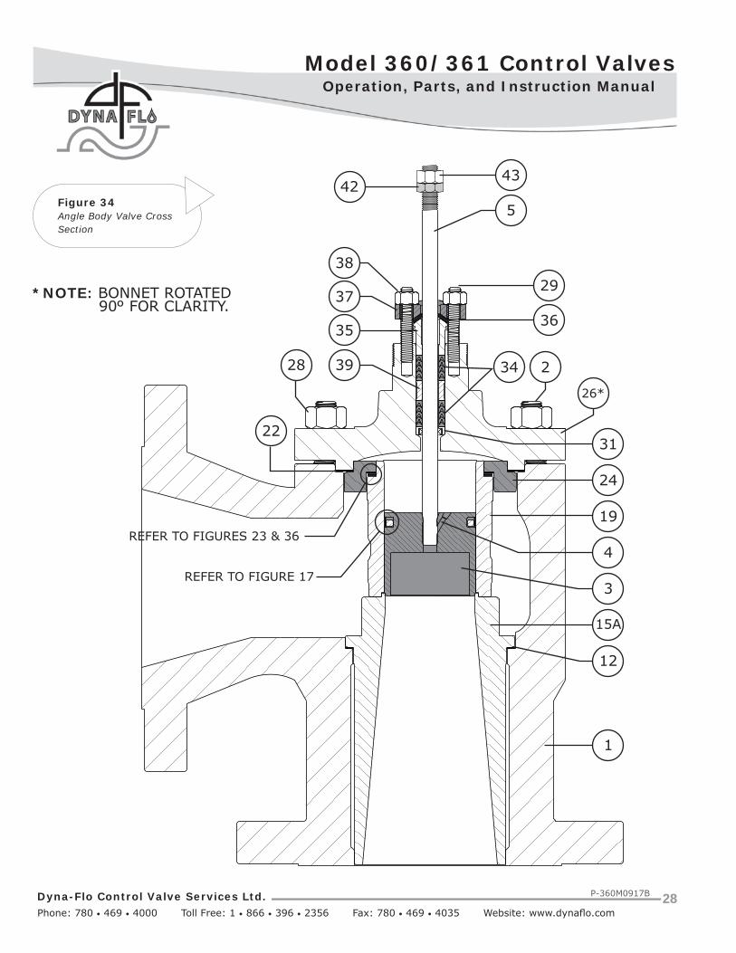
Figure 34Angle Body Valve CrossSection
4342
5
36
2938
37
35
3439 228
24
3122
19
4
15A
12
3
1
REFER TO FIGURES 23 & 36
REFER TO FIGURE 17
26*
*NOTE: BONNET ROTATED 90O FOR CLARITY.
Model 360/361 Control Valves
Dyna-Flo Control Valve Services Ltd. Phone: 780 • 469 • 4000 Toll Free: 1 • 866 • 396 • 2356 Fax: 780 • 469 • 4035 Website: www.dynafl o.com
P-360M0917B 29
Operation, Parts, and Instruction Manual
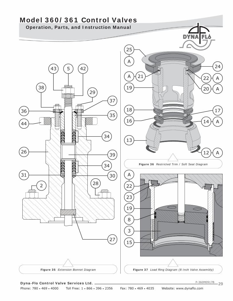
Figure 37 Load Ring Diagram (8 Inch Valve Assembly)Figure 35 Extension Bonnet Diagram
Figure 36 Restricted Trim / Soft Seat Diagram
25
A24
22 A
20 A
A 21
19
18
16
17
14 A
13
12 A
A
22
23
19
3
15
8
43 425
38
36
44
29
37
35
39
34
34
3031
2 28
26
27

Dyna-Flo Control Valve Services Ltd. Phone: 780 • 469 • 4000 Toll Free: 1 • 866 • 396 • 2356 Fax: 780 • 469 • 4035 Website: www.dynafl o.com
Model 360/361 Control Valves
P-360M0917B 30
Operation, Parts, and Instruction Manual
Table 7
Valve Stem Connection Assembly Torque and Pin ReplacementVSC DiameterInches (mm)
Torquelbf-ft. (N•m)
Hole SizeInches (mm)
3/8 (9.5) 25 - 35 (34 - 47) 0.095 - 00.97 (2.41 - 2.46)
1/2 (12.7) 60 - 85 (81 - 115) 0.126 - 0.128 (3.20 - 3.25)
3/4 (19.1) 175 - 250 (237 - 339) 0.189 - 0.192 (4.80 - 4.88)
1 (25.4) 310 - 355 (420 - 481) 0.251 - 0.254 (6.38 - 6.45)
Table 6Packing Nut Torque Values
Valve Stem Diamter
Inch (mm)
ASMEClass
PTFE Single and Double Type Packing Graphite Single and Double Type PackingMin. Torque Max. Torque Min. Torque Max. Torque
lbf-in. N•m lbf-in. N•m lbf-in. N•m lbf-in. N•m
3/8 (9.5)150 9 1 17 2 27 3 44 5300 17 2 27 3 35 4 53 6600 27 3 35 4 53 6 71 8
1/2 (12.7)150 17 2 35 4 44 5 71 8300 27 3 44 5 58 7 89 10600 35 4 58 7 80 9 124 14
3/4 (19.1)150 44 5 71 8 97 11 150 17300 62 7 97 11 133 15 204 23600 89 10 133 15 186 21 274 31
1 (25.4)300 106 12 159 18 230 26 336 38600 150 17 221 25 310 35 469 53
Table 5
Body to Bonnet Stud TorqueValve Sizes (Inch) Bolt Torques
Globe Body Valves
Angle Body Valves
B7B7 Fluorokote #1
B7MB7M Fluorokote #1
B8M CL2 (strain hardened)B8M CL1 (annealed)
N•m lbf-ft. N•m lbf-ft. N•m lbf-ft.
1 1 127 94 102 75 62 46
1-1/2, 1-1/2x1, 2, or
2x12 or 2x1 88 65 71 52 43 32
- 3(1) 127 94 102 75 62 46
3, 3x2 4 or 4x2 175 129 141 104 87 64
4, 4x3 6 312 230 250 184 153 113
6 - 549 405 549 405 370 273
8 - 746 550 746 550 544 401
NOTES: (1) - 3 inch Angle Body valves require the same size stud as the 1 inch valve bodies.

Model 360/361 Control Valves
Dyna-Flo Control Valve Services Ltd. Phone: 780 • 469 • 4000 Toll Free: 1 • 866 • 396 • 2356 Fax: 780 • 469 • 4035 Website: www.dynafl o.com
P-360M0917B 31
Operation, Parts, and Instruction Manual
PartsKey Description Part Number
1 BodyIf you need a body as a replacement part, order by valve size and stem diameter, serial number and desired material.
2 Stud, Bonnet/BodyNOTE: Anti-Cavitation 2 Stage and Low-Noise III D3Trim may require a bonnet spacer and will requirespecial studs. Consult Dyna-Flo.
Refer to Table 5 for Angle Body stud size equivalents.-B71 inch (4 Required) 1R2848X057D1-1/2 inch (8 Required) 1K2429X056D2 inch (8 Required) 1K2429X056D3 inch (8 Required) 1A3781X045D4 inch (8 Required) 1R3690X042D6 inch (12 Required) 1A36563101D8 inch (16 Required) 1D94523101D
-B8M1 inch (4 Required) 1R28483522D1-1/2 inch (8 Required) 1K24293522D2 inch (8 Required) 1K24293522D3 inch (8 Required) 1A3781CL28D4 inch (8 Required) 1R3690CL28D6 inch (12 Required) 1A36563522D8 inch (16 Required) 1D9452CL28D
-B7M1 inch (4 Required) 1R2848B7MDD1-1/2 inch (8 Required) 1K2429B7MDD2 inch (8 Required) 1K2429B7MDD3 inch (8 Required) 1A3781B7MDD4 inch (8 Required) 1R3690B7MDD6 inch (12 Required) 1A3656B7MDD8 inch (16 Required) 1D9452X011D
-B7 Fluorokote #11 inch (4 Required) 1R2848XFK1D1-1/2 inch (8 Required) 1K2429XFK1D2 inch (8 Required) 1K2429XFK1D3 inch (8 Required) 1A3781XFK1D4 inch (8 Required) 1R3690XFK1D6 inch (12 Required) 1A3656XFK1D8 inch (16 Required) 1D9452XFK1D
-B7M Fluorokote #1
Key Description Part Number
1 inch (4 Required) 1R2848XFK3D1-1/2 inch (8 Required) 1K2429XFK3D2 inch (8 Required) 1K2429XFK3D3 inch (8 Required) 1A3781XFK3D4 inch (8 Required) 1R3690XFK3D6 inch (12 Required) 1A3656XFK3D8 inch (16 Required) 1D9452XFK3D
3 Valve Plug Refer to Tables 8-12
4 Pin, S316003/8 inch (9.5 mm) Stem 1V32263507D1/2 inch (12.7mm) Stem 1V32273507D3/4 inch (19.1mm) Stem 1V32603507D1 inch (25.4 mm) Stem 1V3340NT05D
5 Valve Stem Refer to Tables 8-12
6 Backup Ring, Two-Piece Plug Seal, -Fluoroelastomer (Viton)1-5/16 inch port diameter 1V65900529D1-7/8 inch port diameter 1V65920529D2-5/16 inch port diameter 1V55070529D2-7/8 inch port diameter 1V65940529D3-7/16 inch port diameter 1V65960529D4-3/8 inch port diameter 1V65980529D7 inch port diameter 1V66000529D
-Nitrile1-5/16 inch port diameter 1V65900305D1-7/8 inch port diameter 1V65920305D2-5/16 inch port diameter 1V55070305D2-7/8 inch port diameter 1V65940305D3-7/16 inch port diameter 1V65960305D4-3/8 inch port diameter 1V65980305D7 inch port diameter 1V66000305D
-Ethylene Propylene1-5/16 inch port diameter 1V6590X004D1-7/8 inch port diameter 1V6592X003D2-5/16 inch port diameter 1V5507X004D2-7/8 inch port diameter 1V6594X003D3-7/16 inch port diameter 1V6596X003D4-3/8 inch port diameter 1V6598X002D7 inch port diameter 1V6600X002D
7 Seal Ring, Two-Piece Plug Seal,-Carbon-fi lled PTFE (Standard)1-5/16 inch port diameter 1V65910509D1-7/8 inch port diameter 1V65930509D

Dyna-Flo Control Valve Services Ltd. Phone: 780 • 469 • 4000 Toll Free: 1 • 866 • 396 • 2356 Fax: 780 • 469 • 4035 Website: www.dynafl o.com
Model 360/361 Control Valves
P-360M0917B 32
Operation, Parts, and Instruction Manual
Parts (Continued)Key Description Part Number
7 Seal Ring, Two-Piece Plug Seal (Continued)
-Carbon-fi lled PTFE (Standard)
2-5/16 inch port diameter 1V55080509D
2-7/8 inch port diameter 1V65950509D
3-7/16 inch port diameter 1V65970509D
4-3/8 inch port diameter 1V65990509D
7 inch port diameter 1V66010509D
8 Seal Ring, Three-Piece Plug Seal, Carbon-fi lled PTFE/Elgiloy1-5/16 inch port diameter 10A4207X03D1-7/8 inch port diameter 10A4216X03D2-5/16 inch port diameter 10A4206X03D2-7/8 inch port diameter 10A4215X03D3-7/16 inch port diameter 10A5351X06D4-3/8 inch port diameter 10A4223X03D7 inch port diameter 10A2643X03D8 inch port diameter 10A3261X03D
9 Backup Ring, Three-Piece Plug Seal, S31600/S31603 Dual Grade1-5/16 inch port diameter 10A4209X02D1-7/8 inch port diameter 10A4218X01D2-5/16 inch port diameter 10A4208X02D2-7/8 inch port diameter 10A4217X02D3-7/16 inch port diameter 10A5349X02D4-3/8 inch port diameter 10A4224X02D
10 Retaining Ring, Three-Piece Plug Seal, S316001-5/16 inch port diameter 10A4211X01D1-7/8 inch port diameter 10A4220X01D2-5/16 inch port diameter 10A4210X01D2-7/8 inch port diameter 10A4219X01D3-7/16 inch port diameter 10A5350X01D4-3/8 inch port diameter 10A4225X01D
11 Anti-Extrusion Ring, Three-Piece Plug Seal, PolyEtherEtherKetone (PEEK)1-5/16 inch port diameter 23B6125X01D1-7/8 inch port diameter 22B4694X01D2-5/16 inch port diameter 21B9340X01D2-7/8 inch port diameter 22B2617X01D3-7/16 inch port diameter 23B6126X01D4-3/8 inch port diameter 21B9341X01D7 inch port diameter 22B5998X01D
Key Description Part Number
12 Gasket, Seat Ring, S31600/Graphite1 inch 1R2862X011D1-1/2 inch 1R3098X005D2 inch 1R3296X004D3 inch 1R3481X005D4 inch 1J5047X006D6 inch 1U5086X003D8 inch 10A3266X08D
13 Seat Ring Adapter, Reduced Trim, S31600/S31603 Dual Grade Refer to Table 19
14 Gasket, Seat Ring Adapter, S31600/Graphite2 x 1 inch 1R2862X011D3 x 2 inch 1R3296X004D
15 Seat Ring Refer to Tables 20-21
15A Liner, Angle Body Valves Contact Dyna-Flo16 Disk Seat, Soft Seat Valves,
S31600/S31603 Dual Grade Refer to Table 2217 PTFE Disk, Soft Seat Valves,
PTFE Refer to Table 2218 Disk Retainer, Soft Seat Valves,
S31600/S31603 Dual Grade Refer to Table 2219 Cage Refer to Tables 13-18
20 Spiral Wound Gasket- S30400/Graphite1 inch 1R2860X006D1-1/2 inch 1R30999928D2 inch 1R32979928D3 inch 1R34829928D4 inch 1R37229928D6 inch 1U50859928D
-N06600/Graphite1-1/2 x 1 inch 1R28609944D2 x 1 inch 1R28609944D6 x 4 inch 1U50859944D
21 Metal Shim, S304001 inch 16A1936X01D1-1/2 inch 16A1937X01D2 inch 16A1938X01D3 inch 16A1940X01D4 inch 16A1941X01D6 inch 16A1942X01D

Model 360/361 Control Valves
Dyna-Flo Control Valve Services Ltd. Phone: 780 • 469 • 4000 Toll Free: 1 • 866 • 396 • 2356 Fax: 780 • 469 • 4035 Website: www.dynafl o.com
P-360M0917B 33
Operation, Parts, and Instruction Manual
Parts (Continued)Key Description Part Number
22 Gasket, Body/Bonnet, S31600/Graphite1 inch 1R2859X004D1-1/2 inch 1R3101X003D1-1/2 x 1 inch 1R2861X004D2 inch 1R3299X004D2 x 1 inch 1R2861X004D3 inch 1R3484X004D3 x 2 inch 1R3298X003D4 inch 1R3724X004D6 inch 1U5081X005D8 inch 10A3265X11D
23 Load Ring, 8 inch valve only, S17400 20A3267X01D
24 Cage Adapter, Reduced Trim, S31600/S31603 Dual Grade Refer to Table 16
25 Gasket, Cage Adapter, S31600/Graphite1-1/2 x 1 inch 1R3101X003D2 x 1 inch 1R3299X004D3 x 2 inch 1R3484X004D
26 BonnetIf you need a bonnet as a replacement part, order by valve size and stem diameter, serial number and desired material.
27 Baffl e, included as part of extension bonnet assembly28 Nut, Body/Bonnet
-2H1 inch (4 Required) 1C33062407D1-1/2 inch (8 Required) 1A3772X066D2 inch (8 Required) 1A3772X066D3 inch (8 Required) 1A3760X059D4 inch (8 Required) 1A3520X060D6 inch (12 Required) 1A44092407D8 inch (16 Required) 1A44522407D
-2HM1 inch (4 Required) 1C33062HMDD1-1/2 inch (8 Required) 1A37722HMDD2 inch (8 Required) 1A37722HMDD3 inch (8 Required) 1A37602HMDD4 inch (8 Required) 1A35202HMDD6 inch (12 Required) 1A44092HMDD8 inch (16 Required) 1A44522HMDD
Key Description Part Number
-8M1 inch (4 Required) 1C33063525D1-1/2 inch (8 Required) 1A3772X023D2 inch (8 Required) 1A3772X023D3 inch (8 Required) 1A37603525D4 inch (8 Required) 1A35203525D6 inch (12 Required) 1A44093525D8 inch (16 Required) 1A44523525D
-2H Fluorokote #11 inch (4 Required) 1C3306XFK1D1-1/2 inch (8 Required) 1A3772XFK1D2 inch (8 Required) 1A3772XFK1D3 inch (8 Required) 1A3760XFK1D4 inch (8 Required) 1A3520XFK1D6 inch (12 Required) 1A4409XFK1D8 inch (16 Required) 1A4452XFK1D
-2HM Fluorokote #11 inch (4 Required) 1C3306XFK3D1-1/2 inch (8 Required) 1A3772XFK3D2 inch (8 Required) 1A3772XFK3D3 inch (8 Required) 1A3760XFK3D4 inch (8 Required) 1A3520XFK3D6 inch (12 Required) 1A4409XFK3D8 inch (16 Required) 1A4452XFK3D
29 Stud, Packing, B8M, 2 Required3/8 inch (9.5 mm) Stem 1E94413522D1/2 inch (12.7mm) Stem 1E94443525D3/4 inch (19.1mm) Stem 1E94493525D1 inch (25.4 mm) Stem 0V00253522D
30 Lower Wiper, Tefl on3/8 inch (9.5 mm) Stem 1J87210699D1/2 inch (12.7mm) Stem 1E94443522D3/4 inch (19.1mm) Stem 1E94493522D1 inch (25.4 mm) Stem 1J87240699D
31 Packing Box Ring, S31600/S31603 Dual Grade3/8 inch (9.5 mm) Stem 1J87313507D1/2 inch (12.7mm) Stem 1J87323507D3/4 inch (19.1mm) Stem 1J87333507D1 inch (25.4 mm) Stem 1J87343507D
32 Spring, Packing, SST Refer to Table 2433 Special Washer, SST Refer to Table 2434 Packing Set, PTFE Refer to Table 24

Dyna-Flo Control Valve Services Ltd. Phone: 780 • 469 • 4000 Toll Free: 1 • 866 • 396 • 2356 Fax: 780 • 469 • 4035 Website: www.dynafl o.com
Model 360/361 Control Valves
P-360M0917B 34
Operation, Parts, and Instruction Manual
Parts (Continued)Key Description Part Number
35 Packing Follower, S31600/S31603 Dual Grade3/8 inch (9.5 mm) Stem 1E94393507D1/2 inch (12.7mm) Stem 1E94433507D3/4 inch (19.1mm) Stem 1E94473507D1 inch (25.4 mm) Stem 1H98233507D
36 Upper Wiper, Felt3/8 inch (9.5 mm) Stem 1J87260633D1/2 inch (12.7mm) Stem 1J87270633D3/4 inch (19.1mm) Stem 1J87280633D1 inch (25.4 mm) Stem 1J87290633D
37 Packing Flange-Carbon Steel - Plated3/8 inch (9.5 mm) Stem 1E94372410D1/2 inch (12.7mm) Stem 1E94422307D3/4 inch (19.1mm) Stem 1E94482307D1 inch (25.4 mm) Stem 0V00242505D
-S31600/S31603 Dual Grade3/8 inch (9.5 mm) Stem 1E94373507D1/2 inch (12.7mm) Stem 12B6924X01D3/4 inch (19.1mm) Stem 12B6925X01D1 inch (25.4 mm) Stem 0V00243507D
38 Nut, Packing, 8M, 2 Required3/8 inch (9.5 mm) Stem 1E94403525D1/2 inch (12.7mm) Stem 1E94453525D3/4 inch (19.1mm) Stem 1E94463525D1 inch (25.4 mm) Stem 1A34333525D
39 Lantern Ring, Refer to Table 24S31600/S31603 Dual Grade
40 Graphite Filament, Refer to Table 2441 Graphite Ribbon, Refer to Table 2442 Jam Nut, Valve Stem, Steel/Zinc Plated
3/8 inch (9.5 mm) Stem NHJFZ381/2 inch (12.7mm) Stem NHJFZ123/4 inch (19.1mm) Stem NHJFZ341 inch (25.4 mm) Stem NHJFZ100
43 Hex Nut, Valve Stem, Steel/Zinc Plated3/8 inch (9.5 mm) Stem NHFZ381/2 inch (12.7mm) Stem NHFZ123/4 inch (19.1mm) Stem NHFZ341 inch (25.4 mm) Stem NH8FZ100
Key Description Part Number
44 Yoke Locknut, Steel Plated2-1/8 inch (54 mm) Yoke Boss 1E79302306D2-13/16 inch (71 mm) Yoke Boss 1E80742306D3-9/16 inch (127 mm) Yoke Boss 1E83272306D
45 Flow Arrow, S304001 inch 1V10593898D1-1/2” - 8” 1V10603898D
46 Name Tag, S30400 NAMEXSBODYD47 Name Plate, S30400 Refer to Actuator48 Piston Ring, Graphite Refer to Table 26
Parts (Live Loaded Packing)Key Description Part Number
901 Live Loaded Packing Flange,Refer to the P-LLPS Manual
902 O-Ring,Refer to the P-LLPS Manual
903 Spring Washers,Refer to the P-LLPS Manual
904 Live Loaded Packing Follower,Refer to the P-LLPS Manual
905 Live Loaded Packing Box Ring,Refer to the P-LLPS Manual
906 Live Loaded Lower Wiper,Refer to the P-LLPS Manual
907 Live Loaded V-Ring Packing Set,Refer to the P-LLPS Manual
911 Anti-Extrusion Ring,Refer to the P-LLPS Manual
914 Live Loaded Lantern Ring,Refer to the P-LLPS Manual

Model 360/361 Control Valves
Dyna-Flo Control Valve Services Ltd. Phone: 780 • 469 • 4000 Toll Free: 1 • 866 • 396 • 2356 Fax: 780 • 469 • 4035 Website: www.dynafl o.com
P-360M0917B 35
Operation, Parts, and Instruction Manual
Table 8
Globe Valve Plug / Stem* Assembly (Keys 3, 4, & 5) - For Two-Piece Plug Seals with Standard Bonnets
Valve Size Port Size Stem Diameter Travel Plug Material
Inch Inch (mm) Inch (mm) Inch (mm) S41600 HT S31600 S31600 / Alloy 6Seat
S31600 / Alloy 6 Seat & Guide
1”, 2” X 1” 1-5/16 (33.3)3/8 (9.5) 3/4 (19.1) 1V6571XN03D 1V6571XN05D 11A5315XN3D 11A5317XN4D
1/2 (12.7) 3/4 (19.1) 1V6572XN02D 1V6572XN06D 11A5316XN2D 11A5318XN4D
1-1/2 1-7/8 (47.6)3/8 (9.5) 3/4 (19.1) 1V6573XN04D 1V6573XN05D 11A5321XN2D 10A4438XN2D
1/2 (12.7) 3/4 (19.1) 1V6574XN01D 1V6574XN03D 10A4439XN4D 10A4611XN4D
1-1/2 x 1(2) 1-5/16 (33.3)3/8 (9.5) 3/4 (19.1) 1V6571XN04D 1V6571XN09D 11A5315XN7D 11A5317XN7D
1/2 (12.7) 3/4 (19.1) 1V6572XN04D 1V6572XN09D 11A5316XN4D 11A5318XN3D
2, 3 x 2(2) 2-5/16 (58.7)1/2 (12.7) 1-1/8 (28.6) 1V6575XN05D 1V6575XN06D 11A5324XN2D 11A5326XN2D
3/4 (19.1) 1-1/8 (28.6) 1V6576XN01D 1V6576XN03D 11A5325XN2D 11A5327XN1D
3 3-7/16 (87.3)1/2 (12.7) 1-1/2 (38.1) 1V6579XN09D 1V6579XN11D 11A5336XN3D 11A5337XN8D
3/4 (19.1) 1-1/2 (38.1) 1V6580XN01D 1V6580XN03D 11A5014XN1D 11A5338XN1D
4 4-3/8 (111.1)1/2 (12.7) 2 (50.8) 1V6581XN04D 1V6581XN05D 11A5341XN3D 11A5344XN2D
3/4 (19.1) 2 (50.8) 1V6582XN02D 1V6582XN07D 11A5342XN1D 11A5345XN4D
4 x 2-1/2(2) 2-7/8 (73.0)1/2 (12.7) 1-1/2 (38.1) 1V6577XN04D 1V6577XN06D 11A5330XN2D 11A5332XN2D
3/4 (19.1) 1-1/2 (38.1) 1V6578XN01D 1V6578XN02D 11A5331XN2D 11A5333XN1D
6 7 (177.8)3/4 (19.1) 2 (50.8) 1V6584XN04D 1V6584XN06D 11A5350XN3D 21A5351XN6D
1 (25.4) 2 (50.8) 1V6585XN01D 1V6585XN02D 10A5107XN1D 20A0103XN1D
6 x 4(2) 4-3/8 (111.1)3/4 (19.1) 2 (50.8) 1V6582XN01D 1V6582XN05D 11A5342XN4D 11A5345XN7D
1 (25.4) 2 (50.8) 360N6503N1D 360N6503N2D 360N6504N3D 360N6505N5D
NOTE: For 8 inch valves refer to Table 9.
* - Stem material is S20910.
1 - Valve plugs for 8 inch (203.2 mm) ports use one-piece plug seals constructed with a seal ring (Key 8) only, they do not use backup rings (Key 9) or retaining rings (Key 10). These valves are also assembled with a style 1 extension bonnet as standard construction.
2 - Indicates Reduced Trim.
- All S31600 barstock is dual grade S31600/S31603 (316/316L).
Parts Ordering
Whenever corresponding with Dyna-Flo about a 360 Series Control Valves, refer to the nameplate (Key 46) or name tag (Key 47) for the serial number of the unit. Please order by the complete part number (as given in the part lists) of each part required.

Dyna-Flo Control Valve Services Ltd. Phone: 780 • 469 • 4000 Toll Free: 1 • 866 • 396 • 2356 Fax: 780 • 469 • 4035 Website: www.dynafl o.com
Model 360/361 Control Valves
P-360M0917B 36
Operation, Parts, and Instruction Manual
Table 9
Globe Valve Plug / Stem* Assembly (Keys 3, 4, & 5) - For Two-Piece Plug Seals with Style 1 Extension Bonnets
Valve Size Port Size Stem Diameter Travel Plug Material
Inch Inch (mm) Inch (mm) Inch (mm) S41600 HT S31600 S31600 / Alloy 6Seat
S31600 / Alloy 6 Seat & Guide
1 1-5/16 (33.3)3/8 (9.5) 3/4 (19.1) 1V6571XN07D 1V6571XN06D 11A5315X13D 11A5317XN8D
1/2 (12.7) 3/4 (19.1) 1V6572XN03D 1V6572XN12D 11A5316XN3D 11A5318X14D
1-1/2 1-7/8 (47.6)3/8 (9.5) 3/4 (19.1) 1V6573XN07D 1V6573XN12D 11A5321XN4D 10A4438XN3D
1/2 (12.7) 3/4 (19.1) 1V6574XN05D 1V6574XN06D 10A4439XN5D 10A4611X11D
1-1/2x1(2) 1-5/16 (33.3)3/8 (9.5) 3/4 (19.1) 1V6571XN10D 1V6571XN12D 11A5315X17D 11A5317XN5D
1/2 (12.7) 3/4 (19.1) 1V6572XN15D 1V6572XN19D 11A5316X14D 11A5318X13D
23x2(2) 2-5/16 (58.7)
1/2 (12.7) 1-1/8 (28.6) 1V6575XN18D 1V6575XN12D 11A5324XN4D 11A5326XN6D
3/4 (19.1) 1-1/8 (28.6) 1V6576XN11D 1V6576XN13D 11A5325X12D 11A5327X13D
2x1(2) 1-5/16 (33.3) 1/2 (12.7) 3/4 (19.1) 1V6572XN03D 1V6572XN12D 11A5316XN3D 11A5318X14D
3 3-7/16 (87.3)1/2 (12.7) 1-1/2 (38.1) 1V6579XN08D 1V6579XN07D 11A5336X13D 11A5337XN6D
3/4 (19.1) 1-1/2 (38.1) 1V6580X101D 1V6580X103D 11A5014X11D 11A5338X11D
4 4-3/8 (111.1)1/2 (12.7) 2 (50.8) 1V6581XN07D 1V6581XN06D 11A5341X13D 11A5344XN5D
3/4 (19.1) 2 (50.8) 1V6582X102D 1V6582X107D 11A5342X11D 11A5345XN5D
4x2-1/2(2) 2-7/8 (73.0)1/2 (12.7) 1-1/2 (38.1) 1V6577XN05D 1V6577XN12D 11A5330X12D 11A5332X20D
3/4 (19.1) 1-1/2 (38.1) 1V6578XN11D 1V6578XN12D 11A5331X12D 11A5333X11D
6 7 (177.8)3/4 (19.1) 2 (50.8) 1V6584XN05D 1V6584XN11D 11A5350X12D 21A5351XN5D
1 (25.4) 2 (50.8) 1V6585X101D 1V6585X102D 10A5107X11D 20A0103X11D
6x4(2) 4-3/8 (111.1)3/4 (19.1) 2 (50.8) 1V6582X101D 1V6582X105D 11A5342X14D 11A5345X17D
1 (25.4) 2 (50.8) 360N650311D 360N650312D 360N650413D 360N650515D
* - Stem material is S20910.
1 - Valve plugs for 8 inch (203.2 mm) ports use one-piece plug seals constructed with a seal ring (Key 8) only, they do not use backup rings (Key 9) or retaining rings (Key 10). These valves are also assembled with a style 1 extension bonnet as standard construction.
2 - Indicates Reduced Trim.
- All S31600 barstock is dual grade S31600/S31603 (316/316L).

Model 360/361 Control Valves
Dyna-Flo Control Valve Services Ltd. Phone: 780 • 469 • 4000 Toll Free: 1 • 866 • 396 • 2356 Fax: 780 • 469 • 4035 Website: www.dynafl o.com
P-360M0917B 37
Operation, Parts, and Instruction Manual
Table 10
Globe Valve Plug / Stem* Assembly (Keys 3, 4, & 5) - For Three-Piece Plug Seals without Anti-Extrusion Rings(Standard Bonnets)
Valve Size Port Size Stem Diameter Travel Plug Material
Inch Inch (mm) Inch (mm) Inch (mm) S41600 HT S31600 S31600 / Alloy 6Seat
S31600 / Alloy 6 Seat & Guide
1, 2 x 1(2) 1-5/16 (33.3)3/8 (9.5) 3/4 (19.1) 20A4103XN5D 20A4103XN6D 360N1104N3D 20A4104XN2D
1/2 (12.7) 3/4 (19.1) 360N1112N1D 360N1112N2D 360N1113N3D 360N1114N5D
1-1/2 1-7/8 (47.6)3/8 (9.5) 3/4 (19.1) 20A6711XN3D 20A6711XN4D 360N5138N3D 22A5941XN2D
1/2 (12.7) 3/4 (19.1) 20A4150XN6D 20A4150XN2D 360N5147N3D 20A4151XN5D
1-1/2 x 1(2) 1-5/16 (33.3)3/8 (9.5) 3/4 (19.1) 20A4103XN4D 20A4103XN7D 360N5104N3D 20A4104XN3D
1/2 (12.7) 3/4 (19.1) 360N5112N1D 360N5112N2D 360N5113N3D 360N5114N5D
23 x 2(2) 2-5/16 (58.7)
1/2 (12.7) 1-1/8 (28.6) 20A4097XN6D 20A4097N18D 360N2008N3D 20A4099N10D
3/4 (19.1) 1-1/8 (28.6) 20A4098XN6D 20A4098N18D 360N2181N3D 20A4100N10D
3 3-7/16 (87.3)1/2 (12.7) 1-1/2 (38.1) 20A5414XN6D 20A5414XN5D 360N3342N3D 22A3458XN2D
3/4 (19.1) 1-1/2 (38.1) 20A5342XN8D 20A5342XN2D 360N3351N3D 20A5344XN4D
4 4-3/8 (111.1)1/2 (12.7) 2 (50.8) 20A2641XN4D 20A2641N16D 360N4428N3D 21A0187XN2D
3/4 (19.1) 2 (50.8) 20A4194XN5D 20A4194XN2D 360N4437N3D 20A4197XN1D
4 x 2-1/2(2) 2-7/8 (73.0)1/2 (12.7) 1-1/2 (38.1) 20A9533XN5D 20A9533XN6D 360N9312N3D 20A9534XN9D
3/4 (19.1) 1-1/2 (38.1) 20A4144XN1D 20A4144XN2D 360N9321N3D 20A4146XN1D
6 7 (177.8)3/4 (19.1) 2 (50.8) 20A2642XN5D 20A2642XN6D 360N6532N3D 21A8443XN3D
1 (25.4) 2 (50.8) 20A5621XN5D 20A5621XN6D 360N6541N3D 20A6706XN3D
6 x 4(2) 4-3/8 (111.1)3/4 (19.1) 2 (50.8) 20A4194XN3D 20A4194XN7D 360N6498N3D 20A4197XN3D
1 (25.4) 2 (50.8) 360N6506N1D 360N6506N2D 360N6507N3D 360N6508N5D
8(1) 8 (203.2)
3/4 (19.1) 2 (50.8) 21A5356XN1D 21A5356XN2D 21A5359XN1D 21A5362XN1D
1 (25.4) 2 (50.8) 21A5357XN1D 21A5357XN2D 21A5360XN1D 21A5363XN1D
3/4 (19.1) 3 (76.2) 21A5356XN1D 21A5356XN2D 21A5359XN1D 21A5362XN1D
1 (25.4) 3 (76.2) 21A5357XN1D 21A5357XN2D 21A5360XN1D 21A5363XN1D
* - Stem material is S20910.
1 - Valve plugs for 8 inch (203.2 mm) ports use one-piece plug seals constructed with a seal ring (Key 8) only, they do not use backup rings (Key 9) or retaining rings (Key 10). 8” plug/stems are assembled with a style 1 extension bonnet as standard construction.
2 - Indicates Reduced Trim.
- All S31600 barstock is dual grade S31600/S31603 (316/316L).

Dyna-Flo Control Valve Services Ltd. Phone: 780 • 469 • 4000 Toll Free: 1 • 866 • 396 • 2356 Fax: 780 • 469 • 4035 Website: www.dynafl o.com
Model 360/361 Control Valves
P-360M0917B 38
Operation, Parts, and Instruction Manual
Table 12
Globe Valve Plug / Stem* Assembly (Keys 3, 4, & 5) - Anti-Cav 1 stage with Standard Bonnets (without Anti-Extrusion Rings)
Valve Size Port Size Stem Diameter Travel Plug Material
Inch Inch (mm) Inch (mm) Inch (mm) S42000 HT
1 1-5/16 (33.3) 1/2 (12.7) 3/4 (19.1) 360N1001N8D
1-1/2 1-7/8 (47.6) 1/2 (12.7) 3/4 (19.1) 28A1002XN1D
2 2-5/16 (58.7)1/2 (12.7) 1-1/8 (28.6) 28A1003XN1D
3/4 (19.1) 1-1/8 (28.6) 28A1004XN1D
3 3-7/16 (87.3)1/2 (12.7) 1-1/2 (38.1) 28A1007XN1D
3/4 (19.1) 1-1/2 (38.1) 28A1008XN1D
4 x 2-1/2 2-7/8 (73)1/2 (12.7) 1-1/2 (38.1) 28A1005XN1D
3/4 (19.1) 1-1/2 (38.1) 28A1006XN1D
4 4-3/8 (111.1)1/2 (12.7) 2 (50.8) 360N4002N8D
3/4 (19.1) 2 (50.8) 28A1010XN1D
6 7 (177.8)3/4 (19.1) 2 (50.8) 360N6000N8D
1 (25.4) 2 (50.8) 28A1013XN1D
6x4 4-3/8 (111.1)1/2 (12.7) 2 (50.8) 28A1010XN2D
3/4 (19.1) 2 (50.8) 28A1011XN2D
* - Stem material is S20910.
Table 11
Globe Valve Plug / Stem* Assembly (Keys 3, 4, & 5) - Three-Piece Plug Seals with Anti-Cavitation 2 Stage (Standard Bonnets)
Valve Size Port Size Stem Diameter Travel Plug Material
Inch Inch (mm) Inch (mm) Inch (mm) S42000 HT S31600 / Alloy 6 Seat & Guide
1 1 (25.4) 1/2 (12.7) 1 (25.4) 24A5265XN8D 24A5519XN2D
1-1/2 1-5/16 (33.3) 1/2 (12.7) 1-1/2 (38.1) 24A5266XN2D 24A5286XN2D
2 1-7/8 (47.6)1/2 (12.7) 2 (50.8) 24A3038XN2D 24A5287XN2D
3/4 (19.1) 2 (50.8) 24A5550XN2D 24A5551XN2D
3 2-7/8 (73.0)1/2 (12.7) 3 (76.2) 24A5269XN2D 24A5290XN2D
3/4 (19.1) 3 (76.2) 23A9452XN2D 24A5291XN2D
4 2-7/8 (73.0)1/2 (12.7) 4 (101.6) 360N4462N8D 360N4463N5D
3/4 (19.1) 4 (101.6) 23A5818XN3D 24A5292XN5D
4 x 2(2) 2-5/16 (58.7)1/2 (12.7) 2-1/2 (63.5) 360N4454N8D 360N4455N5D
3/4 (19.1) 2-1/2 (63.5) 360N4458N8D 360N4459N5D
6 5-3/8 (136.5)3/4 (19.1) 4 (101.6) 23A5803XN2D 24A5294XN2D
1 (25.4) 4 (101.6) 24A3028XN5D 24A5295XN3D
* - Stem material is S20910.
2 - Indicated Reduced Trim.
- All S31600 barstock is dual grade S31600/S31603 (316/316L).

Model 360/361 Control Valves
Dyna-Flo Control Valve Services Ltd. Phone: 780 • 469 • 4000 Toll Free: 1 • 866 • 396 • 2356 Fax: 780 • 469 • 4035 Website: www.dynafl o.com
P-360M0917B 39
Operation, Parts, and Instruction Manual
Table 13
Cage (Key 19) - Quck Opening
Valve Size Inch Port Size Cage MaterialGlobe Body Angle Body Inch (mm) S17400 H900 S17400 DH1150 S31600 / ENC
1, 1-1/2x1, 2x1 1, 2x1 1-5/16 (33.3) 2U21503327D 2U21501150D 2U74034893D
1-1/2 2, 3x1-1/2 1-7/8 (47.6) 2U21923327D 2U21921150D 2U72544893D
2, 3x2 4x2 2-5/16 (58.7) 2U22343327D 2U22341150D 2U74044893D
- 3 2-7/8 (73.0) 2U22763327D 2U22761150D 2U74054893D
3 4 3-7/16 (87.3) 2U23183327D 2U23181150D 2U74064893D
4 6 4-3/8 (111.1) 2U23603327D 2U23601150D 2U74074893D
4x2-1/2 - 2-7/8 (73.0) 2U22763327D 2U22761150D 2U74054893D
6 - 7 (177.8) 2U50633327D 2U50631150D 2U80694893D
6x4 - 4-3/8 (111.1) 2V37223327D 2V37221150D 2V37194617D
8 - 8 (203.2) 20A3249X01D 20A3249X02D 20A5469X01D
- All S31600 barstock is dual grade S31600/S31603 (316/316L).
Table 14
Cage (Key 19) - Linear
Valve Size Inch Port Size Cage MaterialGlobe Body Angle Body Inch (mm) S17400 H900 S17400 DH1150 S31600 / ENC
1, 1-1/2x1, 2x1 1, 2x1 1-5/16 (33.3) 2U21563327D 2U21561150D 2U74144893D
1-1/2 2, 3x1-1/2 1-7/8 (47.6) 2U21983327D 2U21983150D 2U74154893D
2, 3x2 4x2 2-5/16 (58.7) 2U22403327D 2U22401150D 2U74164893D
- 3 2-7/8 (73.0) 2U22823327D 2U22821150D 2U74174893D
3 4 3-7/16 (87.3) 2U23243327D 2U23241150D 2U74184893D
4 6 4-3/8 (111.1) 2U23663327D 2U23661150D 2U74194893D
4x2-1/2 - 2-7/8 (73.0) 2U22823327D 2U22821150D 2U74174893D
6 - 7 (177.8) 2U50613327D 2U50611150D 2U80684893D
6x4 - 4-3/8 (111.1) 2V37183327D 2V37181150D 2V37124893D
8 - 8 (203.2) 20A3247X01D 20A3247X05D 20A5468X01D
- All S31600 barstock is dual grade S31600/S31603 (316/316L).

Dyna-Flo Control Valve Services Ltd. Phone: 780 • 469 • 4000 Toll Free: 1 • 866 • 396 • 2356 Fax: 780 • 469 • 4035 Website: www.dynafl o.com
Model 360/361 Control Valves
P-360M0917B 40
Operation, Parts, and Instruction Manual
Table 15
Cage (Key 19) - Equal Percentage
Valve Size Inch Port Size Cage MaterialGlobe Body Angle Body Inch (mm) S17400 H900 S17400 DH1150 S31600 / ENC
1, 1-1/2x1, 2x1 1, 2x1 1-5/16 (33.3) 2U21533327D 2U21531150D 2U74084893D
1-1/2 2, 3x1-1/2 1-7/8 (47.6) 2U21953327D 2U21951150D 2U74094893D
2, 3x2 4x2 2-5/16 (58.7) 2U22373327D 2U22371150D 2U74104893D
- 3 2-7/8 (73.0) 2U22793327D 2U22791150D 2U74114893D
3 4 3-7/16 (87.3) 2U23213327D 2U23211150D 2U74124893D
4 6 4-3/8 (111.1) 2U23633327D 2U23631150D 2U74134893D
4x2-1/2 - 2-7/8 (73.0) 2U22793327D 2U22791150D 2U74114893D
6 - 7 (177.8) 2U50593327D 2U50591150D 2U80674893D
6x4 - 4-3/8 (111.1) 2V37233327D 2V37231150D 2V37134893D
8 - 8 (203.2) 20A3245X01D 20A3245X05D 20A5467X01D
- All S31600 barstock is dual grade S31600/S31603 (316/316L).
Table 16
Cage (Key 19) - Anti-Cavitation (S17400 H900 Cage Material)
Valve SizeInch
Port SizeInch (mm)
StageStage 1
1 1 (25.4) 38A1018X01D
1-1/2 1-5/16 (33.3) 38A1019X01D
2 1-7/8 (47.6) 38A1020X01D
3 2-7/8 (73.0) 38A1023X01D
4 4-3/8 (111.1) 38A1025X01D
4 x 2-1/2(1) 2-7/8 (73.0) 38A1021X01D
6 7 (177.8) 38A1027X01D
8 8 (203.2) 360C8000X1D
1 - Indicates Reduced Trim
Table 17
Cage (Key 19) - Anti-Cavitation (S17400 H900 Cage Material)
Valve SizeInch
Port SizeInch (mm)
StageStage 2
1 1 (25.4) 24A5558X01D
1-1/2 1-5/16 (33.3) 24A5559X02D
2 1-7/8 (47.6) 24A3031X03D
3 2-7/8 (73.0) 23A9453X02D
4 2-7/8 (73.0) 23A5817X03D
4 x 2-1/2(1) 2-5/16 (58.7) 360C4009X1D
6 5-3/8 (136.5) 360C6011X1D
8 7 (177.8) 360C8004X1D
1 - Indicates Reduced Trim

Model 360/361 Control Valves
Dyna-Flo Control Valve Services Ltd. Phone: 780 • 469 • 4000 Toll Free: 1 • 866 • 396 • 2356 Fax: 780 • 469 • 4035 Website: www.dynafl o.com
P-360M0917B 41
Operation, Parts, and Instruction Manual
Table 19
Reduced Trim Adapters (Keys 13 & 24)
- S31600/S31603 Dual Grade Material
Globe Body Inch
Angle BodyInch
PartSeat Ring Adapter (Key 13) Cage Adapter (Key 24)
1-1/2 x 1 2x1 - 1U2218X316D
2x1 - 1U2262X316D 1U1207X316D
- 3 x 1-1/2 1U2304X316D 1U2302X316D
3 x 2 4 x 2 1U2346X316D 1U1246X316D
4 x 2-1/2 - 1U2396X316D 1U1251X316D
- LF2 (ASTM A350/A105 DUAL GRADE FORGED MATERIAL
Globe Body Inch
Angle BodyInch
PartSeat Ring Adapter (Key 13) Cage Adapter (Key 24)
1-1/2 x 1 2x1 - 1U22182449D
2x1 - 1U22622449D 1U12072449D
- 3 x 1-1/2 1U23042449D 1U23022449D
3 x 2 4 x 2 1U23462201D 1U12462201D
4 x 2-1/2 - 1U23962201D 1U12512201D
Table 18
Cage (Key 19) - Low-Noise 3 A1
Valve Size Inch Port Size Cage MaterialGlobe Body Angle Body Inch (mm) S17400 H900 S17400 DH1150 S31600 / ENC
1, 1-1/2 x 1, 2 x 1 1, 2 x 1 1-5/16 (33.3) 2V50233327D 2V50231150D 360C1002X3D
1-1/2 2, 3 x 1-1/2 1-7/8 (47.6) 360C5001X1D 360C5001X2D 360C5002X3D
2, 3 x 2 4 x 2 2-5/16 (58.7) 360C2004X1D 360C2004X2D 360C2005X3D
- 3 2-7/8 (73.0) 360C4004X1D 360C4004X2D 360C4005X3D
3 4 3-7/16 (87.3) 360C3005X1D 360C3005X2D 360C3006X3D
4 6 4-3/8 (111.1) 23A8915X01D 23A8915X03D 23A8915ENCD
4 x 2-1/2 - 2-7/8 (73.0) 360C4004X1D 360C4004X2D 360C4005X3D
6 - 7 (177.8) 23A8913X03D 23A8913115D 360C6003X3D
6 x 4 - 4-3/8 (111.1) 360C6000X1D 360C6000X2D 360C6005X3D
8 - 8 (203.2) 360C8002X01D 360C8002X03D 360C8006X3D
- All S31600 barstock is dual grade S31600/S31603 (316/316L).

Dyna-Flo Control Valve Services Ltd. Phone: 780 • 469 • 4000 Toll Free: 1 • 866 • 396 • 2356 Fax: 780 • 469 • 4035 Website: www.dynafl o.com
Model 360/361 Control Valves
P-360M0917B 42
Operation, Parts, and Instruction Manual
Table 20
Seat Ring (Keys 15) - For Standard Trim
Globe Body Inch
Angle BodyInch
MaterialS41600 HT S31600 S31600 / Alloy 6 Hard Faced Seat
1, 2 x 1 1 1U22254617D 1U22253507D 1U22253910D
1-1/2 2 x 1 1U22194617D 1U22193507D 1U22193910D
1-1/2 x 1 2 1U22204617D 1U22203507D 1U22203910D
2, 3 x 2 4 x 2 1U22264617D 1U22263507D 1U22263910D
- 3 1U22274617D 1U22273507D 1U22273910D
3 4 1U22284617D 1U22283507D 1U22283910D
4 6 1U22294617D 1U22293309D 1U22293910D
6 - 1U50804617D 1U50803309D 1U50803910D
6 x 4 - 2V37194617D 2V37193507D 2V37204605D
8 - 20A3260X01D 20A3260X02D 20A3260X15D
- All S31600 barstock is dual grade S31600/S31603 (316/316L).
Table 21
Seat Ring (Keys 15) - For Anti-Cavitation Trim
Globe Body Inch
StageStage 1 Stage 2
S17400 H900 S31600 / Alloy 6 Hard Faced Seat & Bore S17400 H900 S31600 / Alloy 6
Hard Faced Seat & Bore
1 23A7567X01D 23A7567X02D 24A5231X01D 24A5239X01D
1-1/2 23A7568X01D 23A7568X02D 24A5232X01D 24A5240X01D
2 23A7569X01D 23A7569X02D 24A3039X01D 24A5241X01D
3 24A3016X01D 24A3016X02D 360R338X09D 360R3001X5D
4 24A1135X01D 24A1135X02D 23A5813X01D 24A5244X01D
6 23A5820X03D 23A5820X01D 360R6015X9D 360R6016X5D
8 360R8000X9D 360R8001X3D 360R8002X9D 360R8004X5D
- All S31600 barstock is dual grade S31600/S31603 (316/316L).

Model 360/361 Control Valves
Dyna-Flo Control Valve Services Ltd. Phone: 780 • 469 • 4000 Toll Free: 1 • 866 • 396 • 2356 Fax: 780 • 469 • 4035 Website: www.dynafl o.com
P-360M0917B 43
Operation, Parts, and Instruction Manual
Table 23
Gaskets and Shim Repair Kits (Keys 12, 14, 20, 21, 22, & 25)
Valve Size inchGasket Kit
Globe Valve Angle Valve
1 1 RGASKETX31D
1-1/2 2 RGASKETX32D
1-1/2 x 1 2 x 1 RGASKETX24D
2 - RGASKETX33D
2 x 1 - RGASKETX25D
- 3 RGASKETX34D
- 3 x 1-1/2 RGASKETX26D
3 4 RGASKETX35D
3 x 2 4 x 2 RGASKETX27D
4 6 RGASKETX36D
4 x 2-1/2 - RGASKETX28D
6 - RGASKETX37D
6 x 4 - RGASKETX37D
8 - RGASKETX23D
- All S31600 barstock is dual grade S31600/S31603 (316/316L).
NOTE: Low-Noise III trim requires 2 bonnet gaskets (Key 22). Consult Dyna-Flo.
Table 22
Soft Seat Valve Parts (Keys 16, 17, & 18)
Valve Size inch PartsGlobe Valve Angle Valve Disk Seat (S31600) Disk (PTFE) Disk Retainer (S31600)
1, 2 x 1 1 1V71023507D 1V71010624D 1V71003507D
1-1/2 2, 3 x 1-1/2 1V71053507D 1V71040624D 1V71033507D
1-1/2 x 1 2 x 1 1V71223507D 1V71010624D 1V71213507D
2, 3 x 2 4 x 2 1V71063507D 1V71070624D 1V71083507D
4 x 2-1/2 3 1V71113507D 1V71100624D 1V71093507D
3 - 1V71143507D 1V71130624D 1V71123507D
4 6 1V71173309D 1V71160624D 1V71153309D
6 - 1V71203309D 1V71190624D 1V71183309D
6 x 4 - 2V71243507D 1V71160624D 1V71233507D
8 20A4467X01D 20A4468X01D 10A4466X01D
- All S31600 barstock is dual grade S31600/S31603 (316/316L).
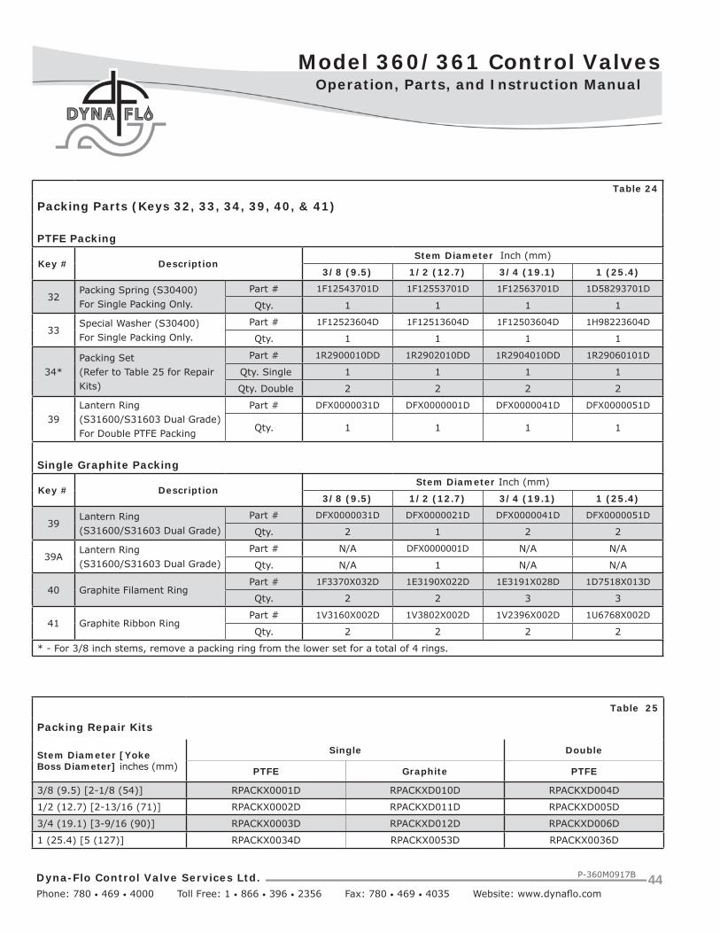
Dyna-Flo Control Valve Services Ltd. Phone: 780 • 469 • 4000 Toll Free: 1 • 866 • 396 • 2356 Fax: 780 • 469 • 4035 Website: www.dynafl o.com
Model 360/361 Control Valves
P-360M0917B 44
Operation, Parts, and Instruction Manual
Table 24
Packing Parts (Keys 32, 33, 34, 39, 40, & 41)
PTFE Packing
Key # DescriptionStem Diameter Inch (mm)
3/8 (9.5) 1/2 (12.7) 3/4 (19.1) 1 (25.4)
32Packing Spring (S30400)For Single Packing Only.
Part # 1F12543701D 1F12553701D 1F12563701D 1D58293701D
Qty. 1 1 1 1
33Special Washer (S30400)For Single Packing Only.
Part # 1F12523604D 1F12513604D 1F12503604D 1H98223604D
Qty. 1 1 1 1
34*Packing Set(Refer to Table 25 for Repair Kits)
Part # 1R2900010DD 1R2902010DD 1R2904010DD 1R29060101D
Qty. Single 1 1 1 1
Qty. Double 2 2 2 2
39Lantern Ring (S31600/S31603 Dual Grade) For Double PTFE Packing
Part # DFX0000031D DFX0000001D DFX0000041D DFX0000051D
Qty. 1 1 1 1
Single Graphite Packing
Key # DescriptionStem Diameter Inch (mm)
3/8 (9.5) 1/2 (12.7) 3/4 (19.1) 1 (25.4)
39Lantern Ring (S31600/S31603 Dual Grade)
Part # DFX0000031D DFX0000021D DFX0000041D DFX0000051D
Qty. 2 1 2 2
39ALantern Ring (S31600/S31603 Dual Grade)
Part # N/A DFX0000001D N/A N/A
Qty. N/A 1 N/A N/A
40 Graphite Filament RingPart # 1F3370X032D 1E3190X022D 1E3191X028D 1D7518X013D
Qty. 2 2 3 3
41 Graphite Ribbon RingPart # 1V3160X002D 1V3802X002D 1V2396X002D 1U6768X002D
Qty. 2 2 2 2
* - For 3/8 inch stems, remove a packing ring from the lower set for a total of 4 rings.
Table 25
Packing Repair Kits
Stem Diameter [YokeBoss Diameter] inches (mm)
Single Double
PTFE Graphite PTFE
3/8 (9.5) [2-1/8 (54)] RPACKX0001D RPACKXD010D RPACKXD004D
1/2 (12.7) [2-13/16 (71)] RPACKX0002D RPACKXD011D RPACKXD005D
3/4 (19.1) [3-9/16 (90)] RPACKX0003D RPACKXD012D RPACKXD006D
1 (25.4) [5 (127)] RPACKX0034D RPACKX0053D RPACKX0036D
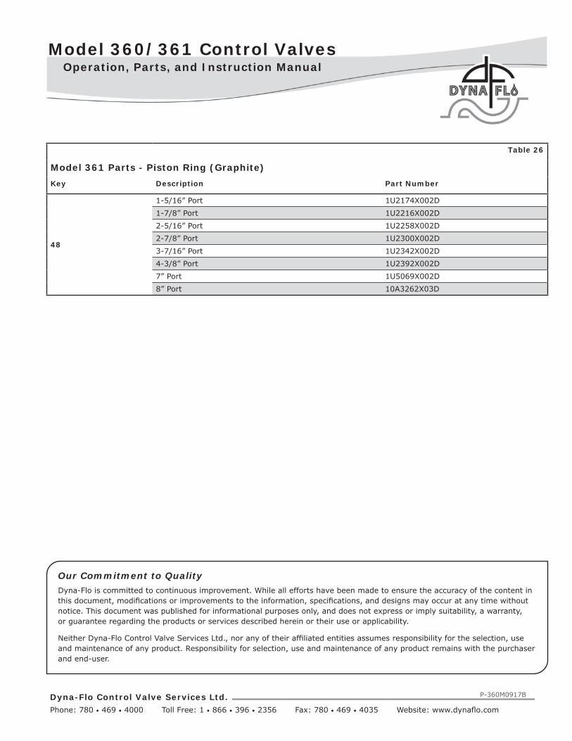
Model 360/361 Control Valves
Dyna-Flo Control Valve Services Ltd. Phone: 780 • 469 • 4000 Toll Free: 1 • 866 • 396 • 2356 Fax: 780 • 469 • 4035 Website: www.dynafl o.com
P-360M0917B
Operation, Parts, and Instruction Manual
Our Commitment to QualityDyna-Flo is committed to continuous improvement. While all efforts have been made to ensure the accuracy of the content in this document, modifi cations or improvements to the information, specifi cations, and designs may occur at any time without notice. This document was published for informational purposes only, and does not express or imply suitability, a warranty, or guarantee regarding the products or services described herein or their use or applicability.
Neither Dyna-Flo Control Valve Services Ltd., nor any of their affi liated entities assumes responsibility for the selection, use and maintenance of any product. Responsibility for selection, use and maintenance of any product remains with the purchaser and end-user.
Table 26
Model 361 Parts - Piston Ring (Graphite)Key Description Part Number
48
1-5/16” Port 1U2174X002D1-7/8” Port 1U2216X002D2-5/16” Port 1U2258X002D2-7/8” Port 1U2300X002D3-7/16” Port 1U2342X002D4-3/8” Port 1U2392X002D7” Port 1U5069X002D8” Port 10A3262X03D

Dyna-Flo Control Valve Services Ltd. Phone: 780 • 469 • 4000 Toll Free: 1 • 866 • 396 • 2356 Fax: 780 • 469 • 4035 Website: www.dynafl o.com
Model 360/361 Control Valves
P-360M0917B
Operation, Parts, and Instruction Manual
This page left intentionally blank.

Model 360/361 Control Valves
Dyna-Flo Control Valve Services Ltd. Phone: 780 • 469 • 4000 Toll Free: 1 • 866 • 396 • 2356 Fax: 780 • 469 • 4035 Website: www.dynafl o.com
P-360M0917B
MODEL NUMBERING SYSTEM
BODY STYLE -- GLOBE A ANGLEVALVE SIZE
31 1 INCH 5 1-1/2 INCH 2 2 INCH 3 3 INCH4 4 INCH 6 6 INCH 8 8 INCH E 10 X 8 INCH
ASME RATING AA 150 B 300 C 600END CONNECTION
FF RF J RTJ N NPT T BWE SCH 40L BWE SCH 80 S SOCKET WELD
BODY MATERIAL LL LCC W WCC M CF8M 9 WC9BOLTING
-- B7 / 2H (STANDARD) A B7M / 2HMB B8M / 8M K B7 / 2H FLUOROKOTE #1L B7M / 2HM FLUOROKOTE #1
TRIM21 TRIM D1 2 TRIM D2 4 TRIM D4 6 TRIM D6
E TRIM DE J TRIM DJPORT SIZE FF FULL PORT R REDUCED PORT
PACKING STYLE
PP SINGLE PTFE V-RING (PRESSURE) J DOUBLE PTFE V-RING (PRESSURE)G SINGLE GRAPHITE (PRESSURE) V DOUBLE PTFE V-RING (VACUUM)R DOUBLE PTFE V-RING (VACUUM / PRESSURE) L LIVE LOADED PTFE V-RING (PRESSURE)T LIVE LOADED GRAPHITE (PRESSURE) D LIVE LOADED DUPLEX (PRESSURE)K LIVE LOADED KALREZ®
YOKE BOSS SIZE 21 2-1/8” (3/8” STEM) 2 2-13/16” (1/2” STEM) 3 3-9/16” (3/4” STEM) 5 5” (1” STEM)PAINT
-- DFPS-01 (STANDARD) 2 DFPS-02 (SEVERE SERVICE)3 DFPS-03 (HIGH TEMPERATURE)
PISTON RING GG GRAPHITE PISTON RING H MULTIPLE GRAPHITE PISTON RINGSCHARACTERISTIC
E
E EQUAL PERCENT L LINEAR Q QUICK OPENINGZ LOW-NOISE III A1 (LINEAR) Y LOW-NOISE III B3 (LINEAR)C LOW-NOISE III C3 (LINEAR) 1 LOW-NOISE III D1 (LINEAR)D LOW-NOISE III D3 (LINEAR)
CHARACTERISTIC (EXTENDED TRAVEL)R MODIFIED EQUAL PERCENT S MODIFIED LINEART MODIFIED QUICK OPENING W MODIFIED LOW-NOISE III A1 (LINEAR)
BONNET STYLESS STANDARD T STANDARD TAPPED E EXTENSION STYLE 1
H EXTENSION STYLE 2SHUT-OFF CLASS 22 CLASS II 3 CLASS III 4 CLASS IV
SAMPLE PART NUMBER: 361 -3AFL-2FP2-GES2
361

Dyna-Flo Control Valve Services Ltd. Phone: 780 • 469 • 4000 Toll Free: 1 • 866 • 396 • 2356 Fax: 780 • 469 • 4035 Website: www.dynafl o.com
Model 360/361 Control Valves
P-360M0917B 48
MODEL NUMBERING SYSTEM
BODY STYLE -- GLOBE A ANGLEVALVE SIZE
31 1 INCH 5 1-1/2 INCH 2 2 INCH 3 3 INCH4 4 INCH 6 6 INCH 8 8 INCH
ASME RATING AA 150 B 300 C 600END CONNECTION
FF RF J RTJ N NPT T BWE SCH 40L BWE SCH 80 S SOCKET WELD
BODY MATERIAL LL LCC W WCC M CF8M 9 WC9BOLTING
-- B7 / 2H (STANDARD) A B7M / 2HMB B8M / 8M K B7 FLUOROKOTE #1 / 2H FLUOROKOTE #1L B7M FLUOROKOTE #1 / 2HM FLUOROKOTE #1
TRIM
51 TRIM D1 2 TRIM D2 4 TRIM D4 5 TRIM D56 TRIM D6 7 TRIM D7 8 TRIM D8 9 TRIM D9L TRIM DL J TRIM DJ T TRIM DT E TRIM DEN TRIM DN R TRIM DR
PORT SIZE FF FULL PORT R REDUCED PORTPACKING STYLE
PP SINGLE PTFE V-RING (PRESSURE) J DOUBLE PTFE V-RING (PRESSURE)G SINGLE GRAPHITE (PRESSURE) V DOUBLE PTFE V-RING (VACUUM)R DOUBLE PTFE V-RING (VACUUM / PRESSURE) L LIVE LOADED PTFE V-RING (PRESSURE)T LIVE LOADED GRAPHITE (PRESSURE) D LIVE LOADED DUPLEX (PRESSURE)K LIVE LOADED KALREZ®
YOKE BOSS SIZE 21 2-1/8” (3/8” STEM) 2 2-13/16” (1/2” STEM) 3 3-9/16” (3/4” STEM) 5 5” (1” STEM)PAINT
-- DFPS-01 (STANDARD) 2 DFPS-02 (SEVERE SERVICE)3 DFPS-03 (HIGH TEMPERATURE)
BACKUP RING / SEAL RING
VV VITON / CARBON-FILLED PTFE E EPDM / CARBON-FILLED PTFEC S31600 / CARBON-FILLED PTFE-ELGILOY K S31600 / KEL-F - ELGILOYP CARBON-FILLED PTFE-ELGILOY (8” 360)R S31600 / CARBON-FILLED PTFE-ELGILOY WITH PEEK AE RINGS
CHARACTERISTIC
E
E EQUAL PERCENT L LINEAR Q QUICK OPENINGA ANTI-CAVITATION 1 STAGE (LINEAR) K ANTI-CAVITATION 2 STAGE (LINEAR)Z LOW-NOISE III A1 (LINEAR) Y LOW-NOISE III B3 (LINEAR)C LOW-NOISE III C3 (LINEAR) 1 LOW-NOISE III D1 (LINEAR)D LOW-NOISE III D3 (LINEAR)
CHARACTERISTIC (EXTENDED TRAVEL)R EQUAL PERCENT - EXTENDED TRAVEL S LINEAR - EXTENDED TRAVELT QUICK OPENING - EXTENDED TRAVEL W LOW-NOISE III A1 (LINEAR) - EXTENDED TRAVELV ANTI-CAVITATION 1 STAGE (LINEAR) -EXTENDED TRAVEL4 LOW-NOISE III A1 (LINEAR) EXTENDED 4” TRAVEL (8” VALVE ONLY)
BONNET STYLESS STANDARD T STANDARD TAPPED E EXTENSION STYLE 1
H EXTENSION STYLE 2SHUT-OFF CLASS 44 CLASS IV 5 CLASS V 6 CLASS VI
SAMPLE PART NUMBER: 360 -3AFL-5FP2-VES4
360

![숙명여자대학교 학생부종합전형 지원gaza.dobong.go.kr/pdf/sookmyung.pdf언수외사(2)언수외사 [400] 가군 나군가군 365 364 숙명여대 363 362 361 360 숭실대](https://img.dokumen.tips/doc/110x75/5e326159939ecb3a92548a49/eeoee-fe-gaza-2.jpg)