Embed Size (px)
Citation preview

Model 2616RC
T1/E1 TDM-Digital Access
Concentrator (T-DAC)
Getting Started Guide
Sales Office:
+1 (301) 975-1000
Technical Support:
+1 (301) 975-1007
E-mail:
WWW:
www.patton.com
Document Number:
11015U1-001 Rev. D
Part Number:
07MD2616RC-GSG
Revised:
April 9, 2009
Important
This is a Class A device and is intended for use in a light industrial environment. It is not intended nor approved for use in an industrial or residential environment.
See
Chapter 2
for installa-tion procedures &
Chapter 3
for configuration procedures

Patton Electronics Company, Inc.
7622 Rickenbacker DriveGaithersburg, MD 20879 USA
Tel: +1 (301) 975-1000Fax: +1 (301) 869-9293
Support: +1 (301) 975-1007Web: www.patton.com
E-Mail: [email protected]
Copyright © 2009, Patton Electronics Company. All rights reserved.
The information in this document is subject to change without notice. Patton Elec-tronics assumes no liability for errors that may appear in this document.
Warranty Information
The software described in this document is furnished under a license and may be usedor copied only in accordance with the terms of such license.
Patton Electronics
warrants all Model 2616RC components to be free from defects,and will—at our option—repair or replace the product should it fail within one yearfrom the first date of the shipment.
This warranty is limited to defects in workmanship or materials, and does not covercustomer damage, abuse or unauthorized modification. If the product fails to performas warranted, your sole recourse shall be repair or replacement as described above.Under no condition shall
Patton Electronics
be liable for any damages incurred bythe use of this product. These damages include, but are not limited to, the following:lost profits, lost savings and incidental or consequential damages arising from the useof or inability to use this product.
Patton Electronics
specifically disclaims all otherwarranties, expressed or implied, and the installation or use of this product shall bedeemed an acceptance of these terms by the user.

3
Summary Table of Contents
1 Introduction.................................................................................................................................................. 13
2 Hardware installation.................................................................................................................................... 19
3 Configuring the T-DAC for operation .......................................................................................................... 31
4 Operation and shutdown .............................................................................................................................. 58
5 Troubleshooting and maintenance................................................................................................................ 60
6 Contacting Patton for assistance ................................................................................................................... 72
A Compliance information .............................................................................................................................. 75
B 68-pin SCSI-to-open-end 6-foot cable (part #10-3096TM68-6) .................................................................. 78
Contents
About this guide...................................................................................................................................................10Audience............................................................................................................................................................... 10Structure............................................................................................................................................................... 10Precautions ........................................................................................................................................................... 11Typographical conventions used in this document................................................................................................ 12
General conventions .......................................................................................................................................12Mouse conventions .........................................................................................................................................12
1 Introduction.................................................................................................................................................. 13Model 2616RC T1/E1 T-DAC overview ..............................................................................................................14Hardware overview ................................................................................................................................................15
WAN ..............................................................................................................................................................15LAN ...............................................................................................................................................................15RS-232 control port ........................................................................................................................................16Power system ..................................................................................................................................................16Central processing unit ...................................................................................................................................16System timing .................................................................................................................................................16Temperature ...................................................................................................................................................16Altitude ...........................................................................................................................................................16Humidity ........................................................................................................................................................16Physical dimensions ........................................................................................................................................16Management services ......................................................................................................................................16LED display ....................................................................................................................................................18
2 Hardware installation.................................................................................................................................... 19Introduction ..........................................................................................................................................................20Unpacking the Model 2616RC T-DAC................................................................................................................20
T-DAC blades installation.....................................................................................................................................20Cable installation...................................................................................................................................................22
Connecting the Ethernet ports ........................................................................................................................22Connecting the 10/100Base-T Ethernet port to an Ethernet switch or hub ...............................................22
Connecting the 10/100Base-T Ethernet port to an Ethernet-capable workstation or PC .................................23Connecting the EIA-561 RS-232 configuration port (DCE configured) .........................................................23Connecting the T1/E1 WAN ports .................................................................................................................24
68-pin SCSI to 8 RJ-45 connectors cable ..................................................................................................2468-pin SCSI to open end cable ..................................................................................................................26
Installing the WAN cable to a punch-down block ...........................................................................................2868-pin SCSI to open end, 6 foot cable (part #10-3096TM68-6)—Obsolete ...................................................2968-pin SCSI to 64-pin female Telco (part #10-3096TM68/64-6) ..................................................................29
Completing the hardware installation ....................................................................................................................30
3 Configuring the T-DAC for operation .......................................................................................................... 31
4

Model 2616RC T-DAC Getting Started Guide
Contents
Introduction ..........................................................................................................................................................32Configuration prerequisites ...................................................................................................................................32Initial configuration through the RS-232 control port ...........................................................................................33
Connecting the DB9-RJ45 adapter with the included cable ............................................................................33Setting up the HyperTerminal (or similar program) session ............................................................................34
Using a browser to complete Model 2616RC configuration ..................................................................................37Displaying the T-DAC 2616RC web administration pages .............................................................................38
Home page overview .................................................................................................................................38Configuring the default gateway .....................................................................................................................40Configuring the system clocking parameters ...................................................................................................41Configuring the DS0 mapping ........................................................................................................................44Configuring line settings and signaling for E1 .................................................................................................46
Accessing the Line Interface Settings .........................................................................................................46Configuring the E1 line interface settings ........................................................................................................47Configuring line settings and signaling for T1 ................................................................................................49
Accessing the Line Interface Settings .........................................................................................................49Configuring the T1 line settings ................................................................................................................50
Enabling/disabling the alarm card ...................................................................................................................52Saving your configuration......................................................................................................................................53Backing up your configuration parameters.............................................................................................................53
Backing up the configuration store in flash memory .......................................................................................55Completing the installation ...................................................................................................................................56
4 Operation and shutdown .............................................................................................................................. 58Introduction ..........................................................................................................................................................59Activating the Model 2616RC...............................................................................................................................59De-activating the Model 2616RC..........................................................................................................................59
5 Troubleshooting and maintenance................................................................................................................ 60Introduction ..........................................................................................................................................................61Fault analysis .........................................................................................................................................................62T1/E1 port test modes...........................................................................................................................................64
DSX1 payload loop (dsx1PayloadLoop) ..........................................................................................................64DSX1 line loop (dsxLineLoop) .......................................................................................................................65
Periodic maintenance ............................................................................................................................................66Calibration ......................................................................................................................................................66
Maintenance..........................................................................................................................................................66Exporting the current Model 2616RC configuration ......................................................................................66
Removing the defective Model 2616RC ....................................................................................................69Installing the replacement Model 2616RC ................................................................................................70Importing a saved configuration ................................................................................................................70Completing the installation .......................................................................................................................71
6 Contacting Patton for assistance ................................................................................................................... 72Introduction ..........................................................................................................................................................73Contact information..............................................................................................................................................73
5
Model 2616RC T-DAC Getting Started Guide
Contents
Warranty Service and Returned Merchandise Authorizations (RMAs)...................................................................73Warranty coverage ..........................................................................................................................................73
Out-of-warranty service .............................................................................................................................73Returns for credit ......................................................................................................................................73Return for credit policy .............................................................................................................................74
RMA numbers ................................................................................................................................................74Shipping instructions ................................................................................................................................74
A Compliance information .............................................................................................................................. 75Compliance ...........................................................................................................................................................76
EMC ...............................................................................................................................................................76Safety ..............................................................................................................................................................76PSTN Regulatory ............................................................................................................................................76
Radio and TV Interference ....................................................................................................................................76Industry Canada Notice ........................................................................................................................................76FCC Part 68 (ACTA) Statement ...........................................................................................................................77CE Declaration of Conformity ..............................................................................................................................77Authorized European Representative .....................................................................................................................77
B 68-pin SCSI-to-open-end 6-foot cable (part #10-3096TM68-6) .................................................................. 78Introduction ..........................................................................................................................................................79
6

List of Figures
1 Model 2616RC T-DAC . . . . . . . . . . . . . . . . . . . . . . . . . . . . . . . . . . . . . . . . . . . . . . . . . . . . . . . . . . . . . . . . . . 142 Model 2616RC T-DAC features . . . . . . . . . . . . . . . . . . . . . . . . . . . . . . . . . . . . . . . . . . . . . . . . . . . . . . . . . . . 153 Model 2616RC front panel LEDs . . . . . . . . . . . . . . . . . . . . . . . . . . . . . . . . . . . . . . . . . . . . . . . . . . . . . . . . . . . 174 Alignment/ESD pin and card handle . . . . . . . . . . . . . . . . . . . . . . . . . . . . . . . . . . . . . . . . . . . . . . . . . . . . . . . . 215 Model 2616RC network and configuration ports . . . . . . . . . . . . . . . . . . . . . . . . . . . . . . . . . . . . . . . . . . . . . . . 226 Ethernet RJ-45 pin and signal definitions for T-DAC . . . . . . . . . . . . . . . . . . . . . . . . . . . . . . . . . . . . . . . . . . . 237 Cross-over RJ-45-to-RJ-45 Ethernet cable diagram . . . . . . . . . . . . . . . . . . . . . . . . . . . . . . . . . . . . . . . . . . . . . . 238 DB-9-to-RJ-45 cable diagram . . . . . . . . . . . . . . . . . . . . . . . . . . . . . . . . . . . . . . . . . . . . . . . . . . . . . . . . . . . . . . 239 SCSI-to-RJ45 6-foot WAN cable . . . . . . . . . . . . . . . . . . . . . . . . . . . . . . . . . . . . . . . . . . . . . . . . . . . . . . . . . . . 2410 WAN cable‘s 68-pin SCSI connector . . . . . . . . . . . . . . . . . . . . . . . . . . . . . . . . . . . . . . . . . . . . . . . . . . . . . . . . 2511 RJ-45 plug . . . . . . . . . . . . . . . . . . . . . . . . . . . . . . . . . . . . . . . . . . . . . . . . . . . . . . . . . . . . . . . . . . . . . . . . . . . . 2512 SCSI-to-open-end WAN cable . . . . . . . . . . . . . . . . . . . . . . . . . . . . . . . . . . . . . . . . . . . . . . . . . . . . . . . . . . . . . 2613 68-pin SCSI connector . . . . . . . . . . . . . . . . . . . . . . . . . . . . . . . . . . . . . . . . . . . . . . . . . . . . . . . . . . . . . . . . . . . 2614 Punch-down block wiring . . . . . . . . . . . . . . . . . . . . . . . . . . . . . . . . . . . . . . . . . . . . . . . . . . . . . . . . . . . . . . . . . 2815 SCSI-to-open-end 6-foot WAN cable (obsolete) . . . . . . . . . . . . . . . . . . . . . . . . . . . . . . . . . . . . . . . . . . . . . . . . 2916 Model 2616RC interface ports . . . . . . . . . . . . . . . . . . . . . . . . . . . . . . . . . . . . . . . . . . . . . . . . . . . . . . . . . . . . . 3317 Connection Description window . . . . . . . . . . . . . . . . . . . . . . . . . . . . . . . . . . . . . . . . . . . . . . . . . . . . . . . . . . . 3418 Connect To window . . . . . . . . . . . . . . . . . . . . . . . . . . . . . . . . . . . . . . . . . . . . . . . . . . . . . . . . . . . . . . . . . . . . . 3419 COM1 Properties window . . . . . . . . . . . . . . . . . . . . . . . . . . . . . . . . . . . . . . . . . . . . . . . . . . . . . . . . . . . . . . . . 3520 Terminal keys configuration . . . . . . . . . . . . . . . . . . . . . . . . . . . . . . . . . . . . . . . . . . . . . . . . . . . . . . . . . . . . . . . 3521 Login window . . . . . . . . . . . . . . . . . . . . . . . . . . . . . . . . . . . . . . . . . . . . . . . . . . . . . . . . . . . . . . . . . . . . . . . . . . 3622 VT-100 top level management window . . . . . . . . . . . . . . . . . . . . . . . . . . . . . . . . . . . . . . . . . . . . . . . . . . . . . . 3623 Ethernet configuration window . . . . . . . . . . . . . . . . . . . . . . . . . . . . . . . . . . . . . . . . . . . . . . . . . . . . . . . . . . . . 3724 2616RC Configuration Menu home page . . . . . . . . . . . . . . . . . . . . . . . . . . . . . . . . . . . . . . . . . . . . . . . . . . . . . 3825 HOME page window panes . . . . . . . . . . . . . . . . . . . . . . . . . . . . . . . . . . . . . . . . . . . . . . . . . . . . . . . . . . . . . . . 3926 Operator Actions buttons . . . . . . . . . . . . . . . . . . . . . . . . . . . . . . . . . . . . . . . . . . . . . . . . . . . . . . . . . . . . . . . . . 3927 IP Routing Information Page . . . . . . . . . . . . . . . . . . . . . . . . . . . . . . . . . . . . . . . . . . . . . . . . . . . . . . . . . . . . . . 4028 IP Routing Information window . . . . . . . . . . . . . . . . . . . . . . . . . . . . . . . . . . . . . . . . . . . . . . . . . . . . . . . . . . . . 4129 System Clocking Configuration page, example 1 . . . . . . . . . . . . . . . . . . . . . . . . . . . . . . . . . . . . . . . . . . . . . . . 4230 System Clocking Configuration page, example 2 . . . . . . . . . . . . . . . . . . . . . . . . . . . . . . . . . . . . . . . . . . . . . . . 4331 Clock Reference Submit Query button . . . . . . . . . . . . . . . . . . . . . . . . . . . . . . . . . . . . . . . . . . . . . . . . . . . . . . . 4332 Clock Reference Submit Query button . . . . . . . . . . . . . . . . . . . . . . . . . . . . . . . . . . . . . . . . . . . . . . . . . . . . . . . 4333 DS0 Mapping Overview window . . . . . . . . . . . . . . . . . . . . . . . . . . . . . . . . . . . . . . . . . . . . . . . . . . . . . . . . . . . 4434 Display Option menu . . . . . . . . . . . . . . . . . . . . . . . . . . . . . . . . . . . . . . . . . . . . . . . . . . . . . . . . . . . . . . . . . . . . 4435 T1/E1 Link Activity Overview page . . . . . . . . . . . . . . . . . . . . . . . . . . . . . . . . . . . . . . . . . . . . . . . . . . . . . . . . . 4636 T1/E1 Link Activity Ports 1 – 4 page. . . . . . . . . . . . . . . . . . . . . . . . . . . . . . . . . . . . . . . . . . . . . . . . . . . . . . . . 4737 WAN Circuit Configuration page, Line Interface Settings . . . . . . . . . . . . . . . . . . . . . . . . . . . . . . . . . . . . . . . . 4738 Line Type pull-down menu . . . . . . . . . . . . . . . . . . . . . . . . . . . . . . . . . . . . . . . . . . . . . . . . . . . . . . . . . . . . . . . 4839 Line Coding pull-down menu with dsx1HDB3(3) selected . . . . . . . . . . . . . . . . . . . . . . . . . . . . . . . . . . . . . . . 4840 Line Build Out pull-down menu with e1pulse(1) selected . . . . . . . . . . . . . . . . . . . . . . . . . . . . . . . . . . . . . . . . 4841 E1 ALARMS PRESENT indicator . . . . . . . . . . . . . . . . . . . . . . . . . . . . . . . . . . . . . . . . . . . . . . . . . . . . . . . . . . 4942 T1/E1 Link Activity Overview page . . . . . . . . . . . . . . . . . . . . . . . . . . . . . . . . . . . . . . . . . . . . . . . . . . . . . . . . . 4943 T1/E1 Link Activity Ports 1 – 4 page. . . . . . . . . . . . . . . . . . . . . . . . . . . . . . . . . . . . . . . . . . . . . . . . . . . . . . . . 4944 WAN Circuit Configuration page, Line Interface Settings . . . . . . . . . . . . . . . . . . . . . . . . . . . . . . . . . . . . . . . . 5045 Line Type pull-down menu with dsx1ESF(2) selected . . . . . . . . . . . . . . . . . . . . . . . . . . . . . . . . . . . . . . . . . . . 5046 Line Coding pull-down menu with dsx1B8ZS(2) selected . . . . . . . . . . . . . . . . . . . . . . . . . . . . . . . . . . . . . . . . 5147 Line Build Out pull-down menu with t1pulse0dB(1) selected . . . . . . . . . . . . . . . . . . . . . . . . . . . . . . . . . . . . . 51
7
Model 2960 RAS Getting Started Guide
48 T1 ALARMS PRESENT indicator on T1/E1 LINK ACTIVITY page . . . . . . . . . . . . . . . . . . . . . . . . . . . . . . . 5149 Alarm Card Information window . . . . . . . . . . . . . . . . . . . . . . . . . . . . . . . . . . . . . . . . . . . . . . . . . . . . . . . . . . . 5250 2616RC Configuration Menu home page . . . . . . . . . . . . . . . . . . . . . . . . . . . . . . . . . . . . . . . . . . . . . . . . . . . . . 5351 IMPORT/EXPORT page . . . . . . . . . . . . . . . . . . . . . . . . . . . . . . . . . . . . . . . . . . . . . . . . . . . . . . . . . . . . . . . . . 5452 Example T-DAC flash memory configuration file displayed in a browser . . . . . . . . . . . . . . . . . . . . . . . . . . . . . 5553 Saving the access server flash memory configuration data as a text file . . . . . . . . . . . . . . . . . . . . . . . . . . . . . . . . 5654 Payload loopback . . . . . . . . . . . . . . . . . . . . . . . . . . . . . . . . . . . . . . . . . . . . . . . . . . . . . . . . . . . . . . . . . . . . . . . 6455 Line Loop . . . . . . . . . . . . . . . . . . . . . . . . . . . . . . . . . . . . . . . . . . . . . . . . . . . . . . . . . . . . . . . . . . . . . . . . . . . . . 6556 IMPORT/EXPORT page . . . . . . . . . . . . . . . . . . . . . . . . . . . . . . . . . . . . . . . . . . . . . . . . . . . . . . . . . . . . . . . . . 6757 Example T-DAC flash memory configuration file displayed in a browser . . . . . . . . . . . . . . . . . . . . . . . . . . . . . 6858 Saving the access server flash memory configuration data as a text file . . . . . . . . . . . . . . . . . . . . . . . . . . . . . . . . 69
8

9
List of Tables
1 General conventions . . . . . . . . . . . . . . . . . . . . . . . . . . . . . . . . . . . . . . . . . . . . . . . . . . . . . . . . . . . . . . . . . . . . . 122 Mouse conventions . . . . . . . . . . . . . . . . . . . . . . . . . . . . . . . . . . . . . . . . . . . . . . . . . . . . . . . . . . . . . . . . . . . . . . 123 LED definitions . . . . . . . . . . . . . . . . . . . . . . . . . . . . . . . . . . . . . . . . . . . . . . . . . . . . . . . . . . . . . . . . . . . . . . . . 184 RJ-45 plug pin-out . . . . . . . . . . . . . . . . . . . . . . . . . . . . . . . . . . . . . . . . . . . . . . . . . . . . . . . . . . . . . . . . . . . . . . 255 WAN cable’s 68 non-terminated twisted-pairs . . . . . . . . . . . . . . . . . . . . . . . . . . . . . . . . . . . . . . . . . . . . . . . . . 276 Symptoms . . . . . . . . . . . . . . . . . . . . . . . . . . . . . . . . . . . . . . . . . . . . . . . . . . . . . . . . . . . . . . . . . . . . . . . . . . . . . 617 LED definitions . . . . . . . . . . . . . . . . . . . . . . . . . . . . . . . . . . . . . . . . . . . . . . . . . . . . . . . . . . . . . . . . . . . . . . . . 628 WAN cable’s 68 non-terminated twisted-pairs . . . . . . . . . . . . . . . . . . . . . . . . . . . . . . . . . . . . . . . . . . . . . . . . . 79

About this guideThis guide describes installing and configuring a Patton Electronics Model 2616RC TDM-Digital Access Con-centrator (T-DAC). By the time you are finished with this guide, your T-DAC will be connected to T1/E1 lines and transferring data. The instructions in this guide are based on the following assumptions:
• The T-DAC will connect to T1/E1 lines
• There is a LAN connected to the Ethernet port of the T-DAC
AudienceThis guide is intended for the following users:
• Operators
• Installers
• Maintenance technicians
StructureThis guide contains the following chapters and appendices:
• Chapter 1 describes the T-DAC
• Chapter 2 describes installing the T-DAC hardware
• Chapter 3 describes configuring the T-DAC for use
• Chapter 4 details how to power up and deactivate the T-DAC
• Chapter 5 contains troubleshooting and maintenance information
• Chapter 6 contains information on contacting Patton technical support for assistance
For best results, read the contents of this guide before you install the T-DAC.
10

Model 2616RC T-DAC Getting Started Guide
About this guide
PrecautionsNotes and cautions, which have the following meanings, are used throughout this guide to help you become aware of potential T-DAC problems. Warnings relate to personal injury issues, and Cautions refer to potential property damage.
Note Calls attention to important information.
Safety when working with electricity
The shock hazard symbol and WARNING heading indicate a potential electric shock hazard. Strictly follow the warning instructions to avoid injury caused by electric shock.
The alert symbol and WARNING heading indicate a potential safety hazard. Strictly follow the warning instructions to avoid personal injury.
The shock hazard symbol and CAUTION heading indicate a potential electric shock hazard. Strictly follow the instructions to avoid property damage caused by electric shock.
The alert symbol and CAUTION heading indicate a potential haz-ard. Strictly follow the instructions to avoid property damage.
• The Model 2616RC shall be installed in a restricted access location accessi-ble only to authorized personnel.
• This unit contains no user-serviceable parts. Refer servicing to qualified personnel.
• When removing cards from a shelf under power, some of the components such as the DC converters may be extremely hot. Handle by the card guides only.
• To prevent accidental electrical short circuits, align the card correctly between the card guides before you insert it in the slot.
In accordance with the requirements of council directive 2002/96/EC on Waste of Electrical and Electronic Equipment (WEEE), ensure that at end-of-life you separate this product from other waste and scrap and deliver to the WEEE collection system in your country for recycling.
WARNING
WARNING
CAUTION
CAUTION
WARNING
11

Model 2616RC T-DAC Getting Started Guide
About this guide
Typographical conventions used in this documentThis section describes the typographical conventions and terms used in this guide.
General conventionsThe procedures described in this manual use the following text conventions:
Mouse conventionsThe following conventions are used when describing mouse actions:
Table 1. General conventions
Convention Meaning
Garamond blue type Indicates a cross-reference hyperlink that points to a figure, graphic, table, or section heading. Clicking on the hyperlink jumps you to the ref-erence. When you have finished reviewing the reference, click on the Go to Previous View button in the Adobe® Acrobat® Reader toolbar to return to your starting point.
Futura bold type Indicates the names of menu bar options.Italicized Futura type Indicates the names of options on pull-down menus.
Futura type Indicates the names of fields or windows.
Garamond bold type Indicates the names of command buttons that execute an action.
< > Angle brackets indicate function and keyboard keys, such as <SHIFT>, <CTRL>, <C>, and so on.
Are you ready? All system messages and prompts appear in the Courier font as the system would display them.
% dir *.* Bold Courier font indicates where the operator must type a response or command
Table 2. Mouse conventions
Convention Meaning
Left mouse button This button refers to the primary or leftmost mouse button (unless you have changed the default configuration).
Right mouse button This button refers the secondary or rightmost mouse button (unless you have changed the default configuration).
Point This word means to move the mouse in such a way that the tip of the pointing arrow on the screen ends up resting at the desired location.
Click Means to quickly press and release the left or right mouse button (as instructed in the procedure). Make sure you do not move the mouse pointer while clicking a mouse button.
Double-click Means to press and release the same mouse button two times quicklyDrag This word means to point the arrow and then hold down the left or right mouse but-
ton (as instructed in the procedure) as you move the mouse to a new location. When you have moved the mouse pointer to the desired location, you can release the mouse button.
12
Chapter 1 Introduction
Chapter contentsModel 2616RC T1/E1 T-DAC overview ..............................................................................................................14Hardware overview ................................................................................................................................................15
WAN ..............................................................................................................................................................15LAN ...............................................................................................................................................................15RS-232 control port ........................................................................................................................................16Power system ..................................................................................................................................................16Central processing unit ...................................................................................................................................16System timing .................................................................................................................................................16Temperature ...................................................................................................................................................16Altitude ...........................................................................................................................................................16Humidity ........................................................................................................................................................16Physical dimensions ........................................................................................................................................16Management services ......................................................................................................................................16LED display ....................................................................................................................................................18
13

Model 2616RC T-DAC Getting Started Guide
1 • Introduction
Model 2616RC T1/E1 T-DAC overviewThe Model 2616RC (see figure 1) provides 16 T1/E1 ports. A built-in digital cross-connect switch provides completely flexible grooming: the capability to connect any DS0-channel to any other DS0-channel from the WAN uplink ports or the T1/E1 ports. The T-DAC combines a time-slot multiplexer and a centralized web-based management system on a front and rear blade for insertion in a Patton ForeFront chassis with a chassis mid-plane architecture. The front blade contains LED status indicators, an RS-232 configuration port and a 10/100 Ethernet management port. The rear blade contains the T1/E1 WAN port connections. The 16 T1/E1 ports connect to channelized T1 or E1 network connections.
Each WAN port terminates T1/E1 with flexible any-to-any DS0 mapping. The entire system can be managed in-band (via T1/E1 Frame Relay/PPP links) or out-of-band from a web browser by means of SNMP/HTTP-based management screens.
Figure 1. Model 2616RC T-DAC
Model 2616RC T1/E1 T-DAC overview 14

Model 2616RC T-DAC Getting Started Guide
1 • Introduction
Hardware overviewThe Model 2616RC combines transmission and networking technology concentrating 16 T1/E1 WAN links into a single slot blade for a Patton ForeFront chassis. The T-DAC front blade (see figure 2) contains a full set of LED status indicators presented on the front panel, and an RS-232 async control port. The rear blade pre-sents electrical connections for T1/E1 WAN ports as well as an alarm LED.
Figure 2. Model 2616RC T-DAC features
WANThe 2616RC includes 4, 8, 12, or 16 ports selectable for T1 or E1 operation. The T1/E1 ports may be con-nected to ATM/FR/DDN/IP network backbones and are accessible via the 68-pin SCSI connector in the rear of the unit. Also included are:
• 4 to 16 built-in T1/E1 CSU/DSUs
• T1 1.544 Mbps with D4 or ESF framing, AMI or B8ZS line coding, FCC part 68 compliant
• E1 2.048 Mbps multi-framing with or without CRC4 framing, AMI/HDB3 line coding, CTR-12, and CTR-13 compliant
• Built-in fuses and surge protectors
LANThe 10/100-Mbps Ethernet LAN port is presented on an RJ-45 connector with an auto-sensing/full-duplex 10Base-T or 100Base-T interface. Also included are:
• 100Base-TX half-/full-duplex operation (100 + 100)
Midplane
Rear Blade
Front Rear
Side view
Front Blade
Hardware overview 15

Model 2616RC T-DAC Getting Started Guide
1 • Introduction
• 10Base-T half-/full-duplex operation (10 + 10)
• Auto detection and fallback
• 10/100 Mbps link and status indicators
RS-232 control portThe RS-232 port provides for initial configuration of the Model 2616RC. The RS-232 port supports:
• Asynchronous data rates of 19.2 kbps, 8 data bits, no parity, 1 stop bit.
• An RJ-45 connector with EIA-561 pinouts
• A management interface that supports VT-100 terminals
• Hardware flow control (RTS and CTS)
Power systemThe 2616RC obtains power from the Patton ForeFront chassis. Total power consumption is a maximum of 43 watts provided by modular power supplies installed in the Patton ForeFront chassis.
Central processing unitThe 2616RC employs an Intel i960VH RISC processor operating at 100 MHz/100 Mips. The CPU controls the memory, front/back-panel and management interface for WAN time slot mapping, local switching, loop-back and the management system. The memory holds:
• 4 MB Flash ROM
• 8 MB EDO DRAM
System timingThe T1/E1 T-DAC’s system timing may be derived from an internal clock from an on-board chip, external BITS clock, or a network clock from one of the T1/E1 WAN ports or from the ForeFront system chassis clock. The clock source may be configured in primary, secondary, or slave mode.
The system timing is configured through the NMS.
TemperatureOperating range: 32–122˚F (0–50˚C)
AltitudeMaximum operating altitude: 15,000 feet (4,752 meters)
Humidity5 to 95% relative humidity (RH), non-condensing
Physical dimensions• 1.75 inches (4.44 cm) height, standard 19-inch (48.26 cm) width, 12-inch (30.48 cm) depth
Management services• Out-of-Band RS-232 configuration port for management and control
Hardware overview 16
Model 2616RC T-DAC Getting Started Guide 1 • Introduction
• SNMP version 1 configuration management
• MIB II
• TELNET via Ethernet
• SYSLOG Client
• Remote Software Upgrade via FTP
• Built-in HTTP server for complete configuration and control using a standard web browser
• Frame Relay or PPP in-band management via T1/E1 DS0s.
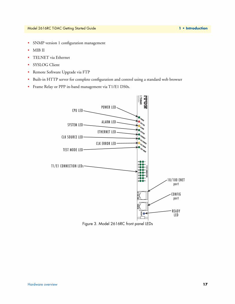
Figure 3. Model 2616RC front panel LEDs
Hardware overview 17

Model 2616RC T-DAC Getting Started Guide 1 • Introduction
LED displayFront panel LEDs (figure 3 on page 17) display the status of the WAN ports, the T1/E1 ports, the Ethernet LAN port, power, and the alarms. The LEDs are described in table 3.
Table 3. LED definitions
LED Color Status Meaning
POWER Green On solid Power is being applied. No action recommended.Flashing The 2616RC has detected a power failure on a power bus.
Off No input power is being applied.CPU FAIL Red On solid CPU is unable to load the software from FLASH to RAM for operation.
Off The CPU is operating normally.ALARM Yellow On solid A minor alarm condition has been detected.
Flashing A major alarm condition has been detected.Off The Model 2616RC is operating normally.
SYSTEM Green Flashing The Model 2616RC is operating normally.Off The Model 2616RC is not functioning properly.
ETHERNET Green On solid Link status is nominal for the Ethernet port. No action recommended.Off A valid link has not been detected.
CLK SOURCE Green On solid The 2616RC is set as the Master Clock source.Flashing The 2616RC is set as the secondary clock source.
Off The 2616RC is set as the slave, getting its clock from the H.110 Bus.CLK ERROR Yellow On solid Master Clock source has been lost and the 2616RC is using the secondary source
for its clock.Flashing Master Clock source and the Secondary Clock source have been lost and the 2616RC
is using its internal crystal for its clock. Off No clock errors currently detected.
TEST MODE Green On solid One or more T1/E1 ports or T1/E1 ports is in test mode.Flashing One or more of the T1/E1 ports or the T1/E1 ports is in test mode and errors have
been received.Off None of the T1/E1 ports is operating in test mode.
T1/E1 CONNECTION(LEDs 1–16)
Green On solid The port is activated, linked, and operating normally.Flashing The port is activated but not linked or in an error state.
READY Blue On Card ready for removal from Patton ForeFront chassis.Off Card not ready for removal from Patton ForeFront chassis.
Hardware overview 18

Chapter 2 Hardware installation
Chapter contentsIntroduction ..........................................................................................................................................................20Unpacking the Model 2616RC T-DAC................................................................................................................20T-DAC blades installation.....................................................................................................................................20Cable installation...................................................................................................................................................22
Connecting the Ethernet ports ........................................................................................................................22Connecting the 10/100Base-T Ethernet port to an Ethernet switch or hub ...............................................22
Connecting the 10/100Base-T Ethernet port to an Ethernet-capable workstation or PC .................................23Connecting the EIA-561 RS-232 configuration port (DCE configured) .........................................................23Connecting the T1/E1 WAN ports .................................................................................................................24
68-pin SCSI to 8 RJ-45 connectors cable ..................................................................................................2468-pin SCSI to open end cable ..................................................................................................................26
Installing the WAN cable to a punch-down block ...........................................................................................2868-pin SCSI to open end, 6 foot cable (part #10-3096TM68-6)—Obsolete ...................................................2968-pin SCSI to 64-pin female Telco (part #10-3096TM68/64-6) ..................................................................29
Completing the hardware installation ....................................................................................................................30
19

Model 2616RC T-DAC Getting Started Guide 2 • Hardware installation
IntroductionThis chapter contains the following procedures for installing the Model 2616RC T-DAC:
Note Before installing the T-DAC, you will need to obtain the line type and encoding of the T1/E1 line from your local telephone company (Telco).
• “Unpacking the Model 2616RC T-DAC”—lists the contents in the T-DAC shipping container
• “T-DAC blades installation”—describes installing the T-DAC on a flat surface or in a standard 19-inch rack
• “Cable installation” on page 22—describes installing the power and network interface cables
• “Completing the hardware installation” on page 30—describes testing the T-DAC hardware to verify that it is ready for software configuration
Unpacking the Model 2616RC T-DACInspect the shipping carton for external damage. Note any damage before removing the container contents. Report equipment damage to the shipping carrier immediately for claim purposes. Save all packing materials in case you need to return an item to the factory for servicing.
The T-DAC comes with the following items:
• The Model 2616RC Digital Cross-Connect (T-DAC)
• One RJ45-to-RJ45 cable for use with the console and Ethernet ports
• A DB9-RJ45 (EIA-561) adapter for connecting a PC's serial port to the T-DAC console port
• Model 2616RC T-DAC Getting Started Guide
• CD-ROM containing product literature, the Model 2616RC T1/E1 T-DAC Getting Started Guide, and the Model 2616RC, 3096RC, and 3196RC Administrator's Reference Guide
T-DAC blades installationDo the following:
Note Verify that the rack chassis is properly grounded before installing the T-DAC blades. An adequate ground can be achieved by connecting a #10 AWG ground wire between the rack chassis grounding stud and one of the following ground sources:
• The building ground rod (generally located at the site’s main ser-vice entrance)
• A sprinkler system pipe
• A cold-water pipe
• Building structural steel
1. If you have not done so already, remove the T-DAC from its shipping container.
Note Be sure to wear the anti-static strap to prevent electrostatic damage to the blade.
Introduction 20

Model 2616RC T-DAC Getting Started Guide 2 • Hardware installation
Note The T-DAC should be installed as close as possible to the termination jack provided by the Telco. The location should be well ventilated. Do not block the rack chassis’ cooling vents.
2. Insert the rear blade into the desired slot in the rack chassis. Make sure the blade is seated properly in the slot guides.
Figure 4. Alignment/ESD pin and card handle
3. Gently press the blade into the chassis until the alignment/ESD pin (see figure 4) engages the chassis. When the blade is fully seated, the red buttons in the handles click up automatically, thus locking the han-dle and activating the switch (closed position). The click of the button gives a visual and audible confirma-tion that the board is fully seated.
4. Insert the front blade into the rack chassis slot that corresponds to the slot in which you installed the rear blade. Verify that the buttons in both handles click up to indicate that the board is fully seated and locked into place.
T-DAC blades installation 21
Model 2616RC T-DAC Getting Started Guide 2 • Hardware installation
Cable installationThis section describes installing the network interface cables.
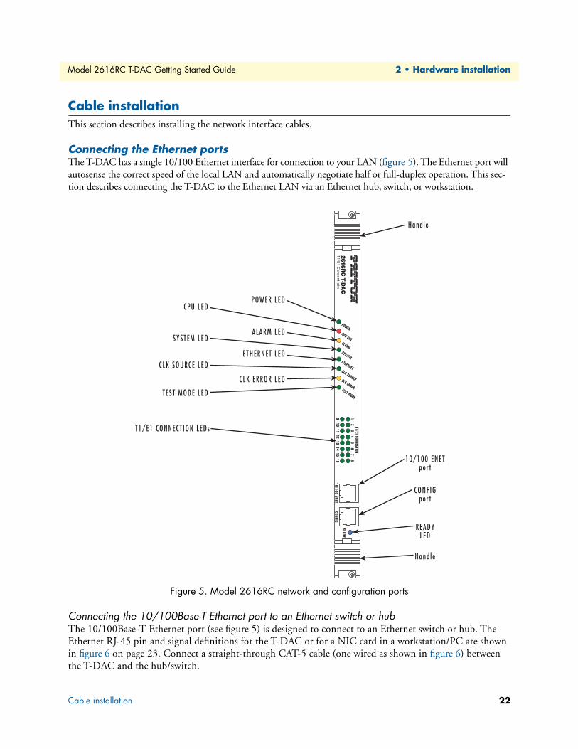
Connecting the Ethernet portsThe T-DAC has a single 10/100 Ethernet interface for connection to your LAN (figure 5). The Ethernet port will autosense the correct speed of the local LAN and automatically negotiate half or full-duplex operation. This sec-tion describes connecting the T-DAC to the Ethernet LAN via an Ethernet hub, switch, or workstation.
Figure 5. Model 2616RC network and configuration ports
Connecting the 10/100Base-T Ethernet port to an Ethernet switch or hubThe 10/100Base-T Ethernet port (see figure 5) is designed to connect to an Ethernet switch or hub. The Ethernet RJ-45 pin and signal definitions for the T-DAC or for a NIC card in a workstation/PC are shown in figure 6 on page 23. Connect a straight-through CAT-5 cable (one wired as shown in figure 6) between the T-DAC and the hub/switch.
Cable installation 22
Model 2616RC T-DAC Getting Started Guide 2 • Hardware installation
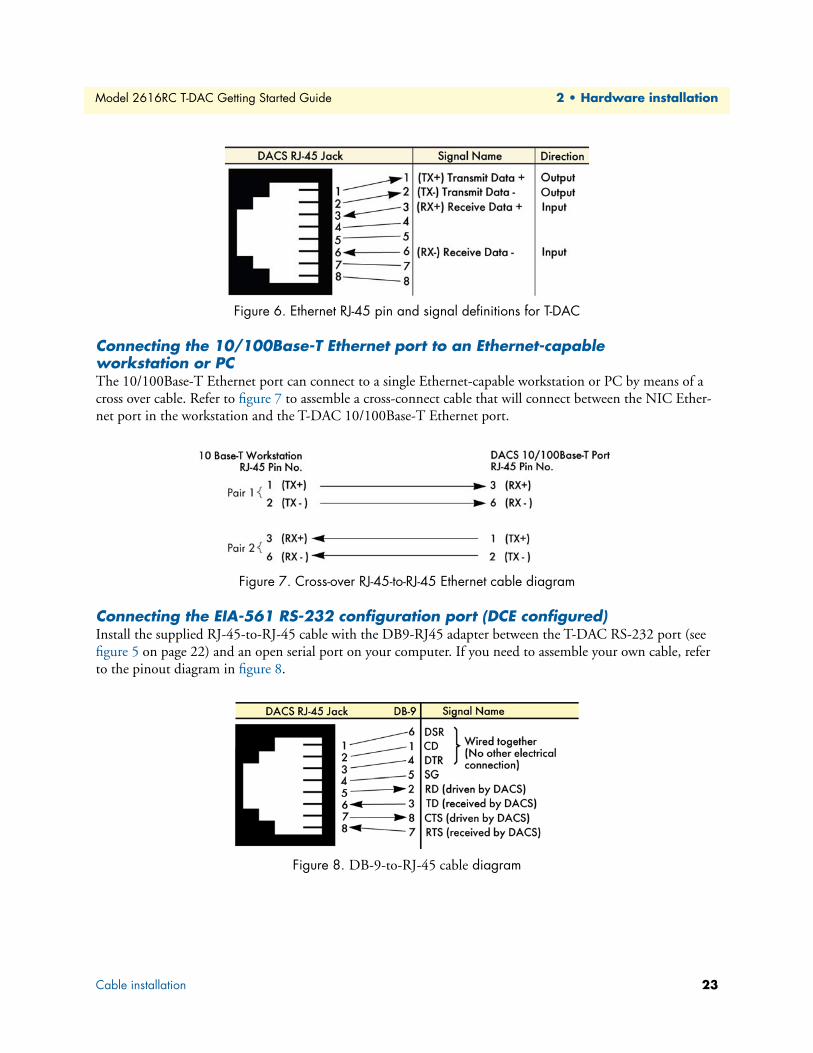
Figure 6. Ethernet RJ-45 pin and signal definitions for T-DAC
Connecting the 10/100Base-T Ethernet port to an Ethernet-capable workstation or PCThe 10/100Base-T Ethernet port can connect to a single Ethernet-capable workstation or PC by means of a cross over cable. Refer to figure 7 to assemble a cross-connect cable that will connect between the NIC Ether-net port in the workstation and the T-DAC 10/100Base-T Ethernet port.
Figure 7. Cross-over RJ-45-to-RJ-45 Ethernet cable diagram
Connecting the EIA-561 RS-232 configuration port (DCE configured)Install the supplied RJ-45-to-RJ-45 cable with the DB9-RJ45 adapter between the T-DAC RS-232 port (see figure 5 on page 22) and an open serial port on your computer. If you need to assemble your own cable, refer to the pinout diagram in figure 8.
Figure 8. DB-9-to-RJ-45 cable diagram
Cable installation 23

Model 2616RC T-DAC Getting Started Guide 2 • Hardware installation
Connecting the T1/E1 WAN portsAn active T1/E1 is not necessary to configure the T-DAC. However, active T1/E1 connections are required when mapping WAN time slots to other WAN time slots. The factory-set default configuration of the Model 2616RC has the T1/E1 ports disabled.
The following types of cables can used to connect the 2616RC to T1/E1 lines:
• 68-pin SCSI to 8 RJ-45 connectors cable, 6 foot (1.8 m) (part #10-3096TM68/8RJ45-6) (see section “68-pin SCSI to 8 RJ-45 connectors cable” for installation details)
• 68-pin SCSI to 16 RJ-45 connectors cable, 6 foot (1.8 m) (part #10-3096TM68/16RJ45-6) (see section “68-pin SCSI to 8 RJ-45 connectors cable” for installation details)
• 68-pin SCSI to open end, 12 foot (3.6 m) (part #10-3096TM68-12) (see section “68-pin SCSI to open end cable” for installation details)
68-pin SCSI to 8 RJ-45 connectors cableThe SCSI-to-RJ-45 cable (see figure 9) connects to the 2616RC via a male SCSI connector (see figure 10). At the other end of the cable, T1/E1 lines terminate on 8 or 16 individual RJ-45 connectors (wired as RJ-48C) (see figure 9). Each RJ-45 terminated T1/E1 line connects directly to a local patch panel or to another T1/E1 device.
Figure 9. SCSI-to-RJ45 6-foot WAN cable
Cable installation 24
Model 2616RC T-DAC Getting Started Guide 2 • Hardware installation
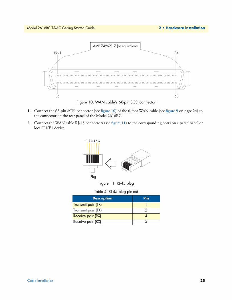
Figure 10. WAN cable‘s 68-pin SCSI connector
1. Connect the 68-pin SCSI connector (see figure 10) of the 6-foot WAN cable (see figure 9 on page 24) to the connector on the rear panel of the Model 2616RC.
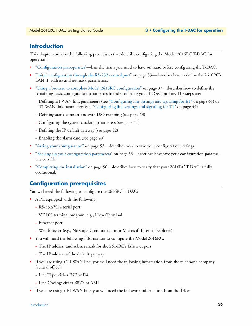
2. Connect the WAN cable RJ-45 connectors (see figure 11) to the corresponding ports on a patch panel or local T1/E1 device.
Figure 11. RJ-45 plug
Table 4. RJ-45 plug pin-out
Description Pin
Transmit pair (TX) 1Transmit pair (TX) 2Receive pair (RX) 4Receive pair (RX) 5
Cable installation 25

Model 2616RC T-DAC Getting Started Guide 2 • Hardware installation
68-pin SCSI to open end cableThe SCSI-to-open-end cable (see figure 12) connects the 2616RC T1/E1 lines to a punch-down block via 24 gauge solid wire (0.5mm). The other end will be unterminated, open-end twisted pairs. Refer to table 5 for punch-down block wiring information.
Figure 12. SCSI-to-open-end WAN cable
Figure 13. 68-pin SCSI connector
68-pin SCSI connector
Cable installation 26

Model 2616RC T-DAC Getting Started Guide 2 • Hardware installation
Note The 64 wires in this cable are grouped into blue and orange binders of 32 wires each. Wires in the blue binder have the same color scheme as wires in the orange binder, so it is important to keep each binder sepa-rated to avoid confusion when connecting to a punch-down block.
Table 5. WAN cable’s 68 non-terminated twisted-pairs
Port/Direction Pairs 68 Pin
PositionsWire Color
CodePort/Directio
n Pairs 68 Pin Positions
Wire Color Code
Port 1/TX 1 135
White/TanTan/White
Port 9/TX 17 1751
Tan/GrayGray/Tan
Port 1/RX 2 236
White/Brown Brown/White
Port 9/RX 18 1852
Brown/Pink Pink/Brown
Port 2/TX 3 337
White/Pink Pink/White
Port 10/TX 19 1953
Brown/OrangeOrange/Brown
Port 2/RX 4 438
White/Orange Orange/White
Port 10/RX 20 2054
Brown/VioletViolet/Brown
Port 3/TX 5 539
White/Violet Violet/White
Port 11/TX 21 2155
Brown/BlueBlue/Brown
Port 3/RX 6 640
White/Blue Blue/White
Port 11/RX 22 2256
Brown/YellowYellow/Brown
Port 4/TX 7 741
White/Yellow Yellow/White
Port 12/TX 23 2357
Brown/GreenGreen/Brown
Port 4/RX 8 842
White/Green Green/White
Port 12/RX 24 2458
Brown/GrayGray/Brown
Port 5/TX 9 943
White/Gray Gray/White
Port 13/TX 25 2559
Pink/OrangeOrange/Pink
Port 5/RX 10 1044
Tan/Brown Brown/Tan
Port 13/RX 26 2660
Pink/VioletViolet/Pink
Port 6/TX 11 1145
Tan/Pink Pink/Tan
Port 14/TX 27 2761
Pink/BlueBlue/Pink
Port 6/RX 12 1246
Tan/OrangeOrange/Tan
Port 14/RX 28 2862
Pink/YellowYellow/Pink
Port 7/TX 13 1347
Tan/VioletViolet/Tan
Port 15/TX 29 2963
Pink/GreenGreen/Pink
Port 7/RX 14 1448
Tan/BlueBlue/Tan
Port 15/RX 30 3064
Pink/GrayGray/Pink
Port 8/TX 15 1549
Tan/YellowYellow/Tan
Port 16/TX 31 3165
Orange/VioletViolet/Orange
Port 8/RX 16 1650
Tan/GreenGreen/Tan
Port 16/RX 32 3266
Orange/BlueViolet/Blue
Cable installation 27

Model 2616RC T-DAC Getting Started Guide 2 • Hardware installation
Installing the WAN cable to a punch-down blockMaterials required:
• punch-down tool
• Plastic tie wraps
• WAN cable pin-out specification
Procedure:
1. Measure the distance between SCSI cable entry point on the punch-down block frame and the farthest port to be wired on the punch-down block (see figure 14).
Figure 14. Punch-down block wiring
2. Strip SCSI cable insulation and shielding based on the measurement made in step 1.
—3367
NOT USED —3468
NOT USED
Table 5. WAN cable’s 68 non-terminated twisted-pairs (Continued)
Port/Direction Pairs 68 Pin
PositionsWire Color
CodePort/Directio
n Pairs 68 Pin Positions
Wire Color Code
Cable installation 28

Model 2616RC T-DAC Getting Started Guide 2 • Hardware installation
3. Review SCSI pin-out (see table 5 on page 27) and punch-block pin-out and cut wires to the required length to reach their respective ports on the punch-down block.
4. Use punch-down tool to press wires down into block terminals.
5. Use cable ties to secure the wires and SCSI cable to the punch-down block (see table 5 on page 27).
Note Cable ties should not allow movement of wires or SCSI cable.
6. Connect the 68-pin SCSI connector of the WAN cable to the connector on the rear panel of the Model 2616RC.
68-pin SCSI to open end, 6 foot cable (part #10-3096TM68-6)—Obsolete 1. This 6-foot WAN cable (see figure 15) connects the 2616RC T1/E1 lines to a punch-down block via 28
gauge wire (0.3mm). Check your punch-down block wire gauge requirements as most punch-down blocks will not hold 28-gauge wire securely in place.
Figure 15. SCSI-to-open-end 6-foot WAN cable (obsolete)
2. See appendix B, “68-pin SCSI-to-open-end 6-foot cable (part #10-3096TM68-6)” on page 78 for pin-out information.
68-pin SCSI to 64-pin female Telco (part #10-3096TM68/64-6)Do the following to install the 6-foot cable adapter for connection of the 2616RC to a Patton E1 balun rack Models 464RC and 466RC.
1. Connect the 68-pin SCSI connector of the WAN cable to the connector on the rear panel of the Model 2616RC.
2. Connect the WAN cable 64-pin Telco connector to the corresponding port on a the balun rack.
Cable installation 29

Model 2616RC T-DAC Getting Started Guide 2 • Hardware installation
Completing the hardware installationThis section verifies that the T-DAC hardware is operational to the point where you can begin configuring the software settings.
Power is delivered from the Patton ForeFront chassis backplane through the 47-pin PICMG 2.11 power con-nectors on the 2616RC blades. Upon insertion into the Patton ForeFront chassis, the Model 2616RC immedi-ately powers up and begins its boot cycle. During the boot cycle the following should occur:
1. The POWER LED illuminates, indicating normal power is being applied to the 2616RC.
2. The green SYSTEM LED begins flashing, indicating the 2616RC is operating normally.
Hardware installation is now complete. To configure the 2616RC for operation, refer to chapter 3, “Configur-ing the T-DAC for operation” on page 31.
Completing the hardware installation 30

Chapter 3 Configuring the T-DAC for operation
Chapter contentsIntroduction ..........................................................................................................................................................32Configuration prerequisites ...................................................................................................................................32Initial configuration through the RS-232 control port ...........................................................................................33
Connecting the DB9-RJ45 adapter with the included cable ............................................................................33Setting up the HyperTerminal (or similar program) session ............................................................................34
Using a browser to complete Model 2616RC configuration ..................................................................................37Displaying the T-DAC 2616RC web administration pages .............................................................................38
Home page overview .................................................................................................................................38Configuring the default gateway .....................................................................................................................40Configuring the system clocking parameters ...................................................................................................41Configuring the DS0 mapping ........................................................................................................................44Configuring line settings and signaling for E1 .................................................................................................46
Accessing the Line Interface Settings .........................................................................................................46Configuring the E1 line interface settings ........................................................................................................47Configuring line settings and signaling for T1 ................................................................................................49
Accessing the Line Interface Settings .........................................................................................................49Configuring the T1 line settings ................................................................................................................50
Enabling/disabling the alarm card ...................................................................................................................52Saving your configuration......................................................................................................................................53Backing up your configuration parameters.............................................................................................................53
Backing up the configuration store in flash memory .......................................................................................55Completing the installation ...................................................................................................................................56
31
Model 2616RC T-DAC Getting Started Guide 3 • Configuring the T-DAC for operation
IntroductionThis chapter contains the following procedures that describe configuring the Model 2616RC T-DAC for operation:
• “Configuration prerequisites”—lists the items you need to have on hand before configuring the T-DAC.
• “Initial configuration through the RS-232 control port” on page 33—describes how to define the 2616RC’s LAN IP address and netmask parameters.
• “Using a browser to complete Model 2616RC configuration” on page 37—describes how to define the remaining basic configuration parameters in order to bring your T-DAC on-line. The steps are:
- Defining E1 WAN link parameters (see “Configuring line settings and signaling for E1” on page 46) or T1 WAN link parameters (see “Configuring line settings and signaling for T1” on page 49)
- Defining static connections with DS0 mapping (see page 43)
- Configuring the system clocking parameters (see page 41)
- Defining the IP default gateway (see page 52)
- Enabling the alarm card (see page 40)
• “Saving your configuration” on page 53—describes how to save your configuration settings.
• “Backing up your configuration parameters” on page 53—describes how save your configuration parame-ters to a file
• “Completing the installation” on page 56—describes how to verify that your 2616RC T-DAC is fully operational.
Configuration prerequisitesYou will need the following to configure the 2616RC T-DAC:
• A PC equipped with the following:
- RS-232/V.24 serial port
- VT-100 terminal program, e.g., HyperTerminal
- Ethernet port
- Web browser (e.g., Netscape Communicator or Microsoft Internet Explorer)
• You will need the following information to configure the Model 2616RC:
- The IP address and subnet mask for the 2616RC’s Ethernet port
- The IP address of the default gateway
• If you are using a T1 WAN line, you will need the following information from the telephone company (central office):
- Line Type: either ESF or D4
- Line Coding: either B8ZS or AMI
• If you are using a E1 WAN line, you will need the following information from the Telco:
Introduction 32
Model 2616RC T-DAC Getting Started Guide 3 • Configuring the T-DAC for operation
- Line Type: either E1 or E1-CRC
- Line Coding: either HDB3 or AMI
Initial configuration through the RS-232 control portInitially you must configure the 2616RC’s IP address and—in rare instances—change the netmask from the default settings.
Note Do not connect power or the Ethernet connection to the Model 2616RC at this time.
Connecting the DB9-RJ45 adapter with the included cableDo the following:
1. Find the DB9-RJ45 adapter for your PC and RJ-45-to-RJ45 cable shipped with your 2616RC T-DAC.
2. Connect the DB9-RJ45 adapter to your PC’s RS-232 serial port.
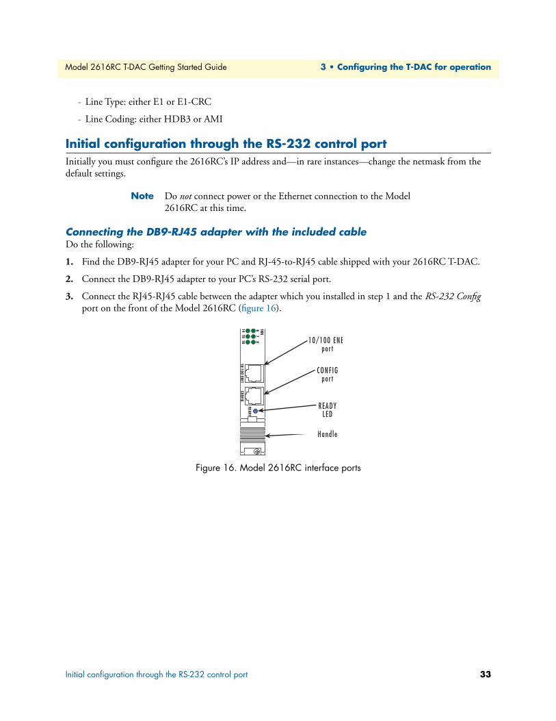
3. Connect the RJ45-RJ45 cable between the adapter which you installed in step 1 and the RS-232 Config port on the front of the Model 2616RC (figure 16).
Figure 16. Model 2616RC interface ports
Initial configuration through the RS-232 control port 33
Model 2616RC T-DAC Getting Started Guide 3 • Configuring the T-DAC for operation
Setting up the HyperTerminal (or similar program) sessionDo the following:
1. At your PC, find the file HYPERTRM.EXE. Open a HyperTerminal session by double-clicking on the file name.
Figure 17. Connection Description window
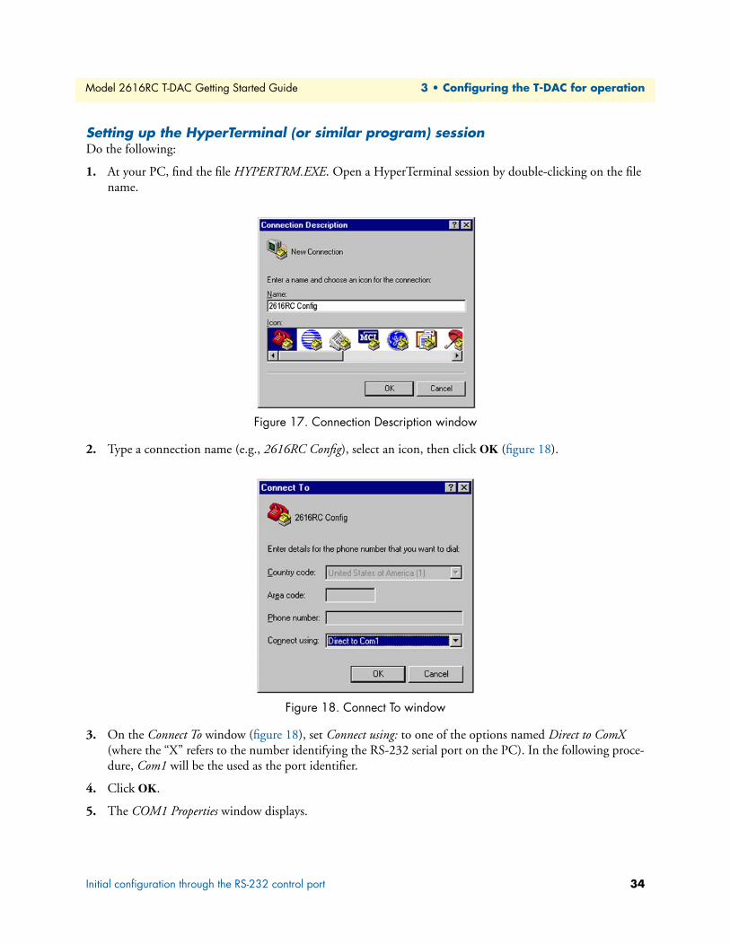
2. Type a connection name (e.g., 2616RC Config), select an icon, then click OK (figure 18).
Figure 18. Connect To window
3. On the Connect To window (figure 18), set Connect using: to one of the options named Direct to ComX (where the “X” refers to the number identifying the RS-232 serial port on the PC). In the following proce-dure, Com1 will be the used as the port identifier.
4. Click OK.
5. The COM1 Properties window displays.
Initial configuration through the RS-232 control port 34

Model 2616RC T-DAC Getting Started Guide 3 • Configuring the T-DAC for operation
6. Configure your COM port settings as shown in figure 19, then click OK.
Figure 19. COM1 Properties window
7. Click on the File menu, then select Properties.
8. Configure the settings for Function, arrow and ctrl keys act as to Terminal keys as shown in figure 20, then click OK.
Figure 20. Terminal keys configuration
Initial configuration through the RS-232 control port 35
Model 2616RC T-DAC Getting Started Guide 3 • Configuring the T-DAC for operation
9. Connect the male end of the 2616RC T-DAC’s power cables to the power outlets.
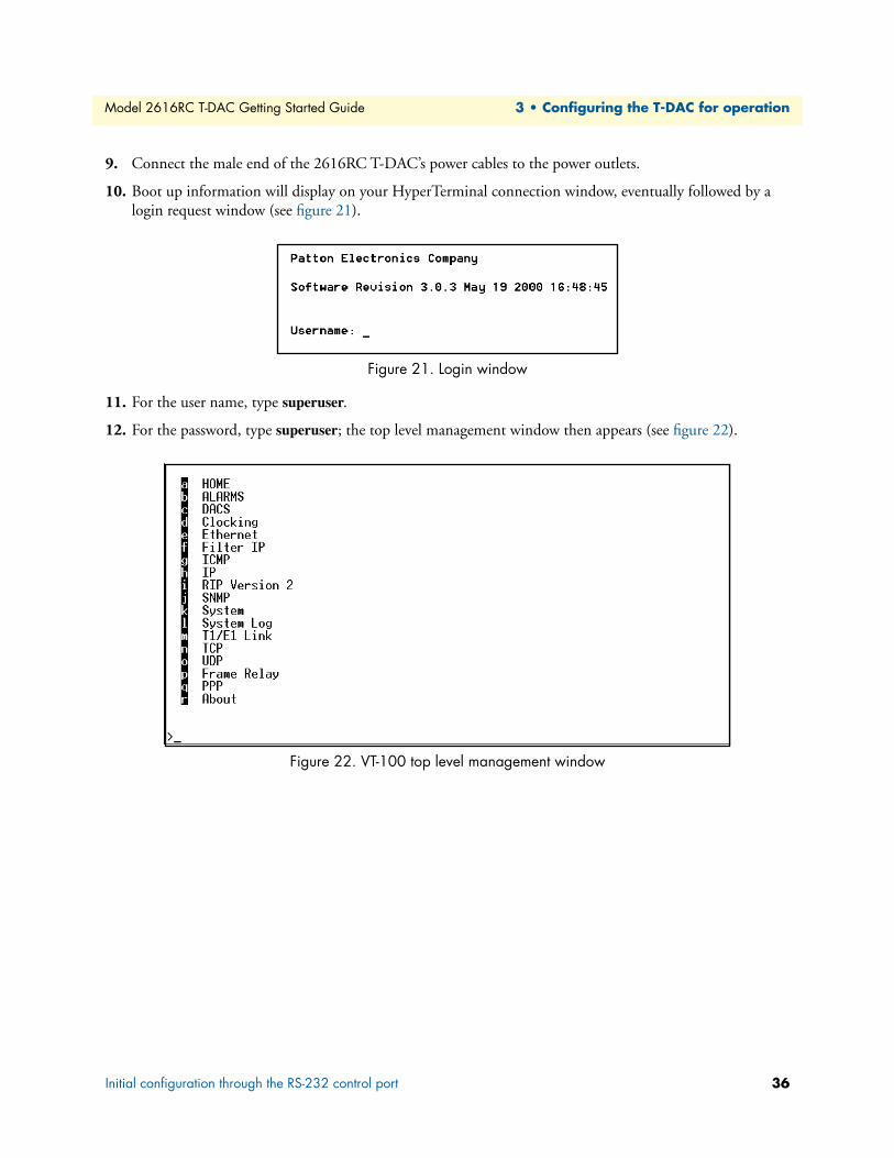
10. Boot up information will display on your HyperTerminal connection window, eventually followed by a login request window (see figure 21).
Figure 21. Login window
11. For the user name, type superuser.
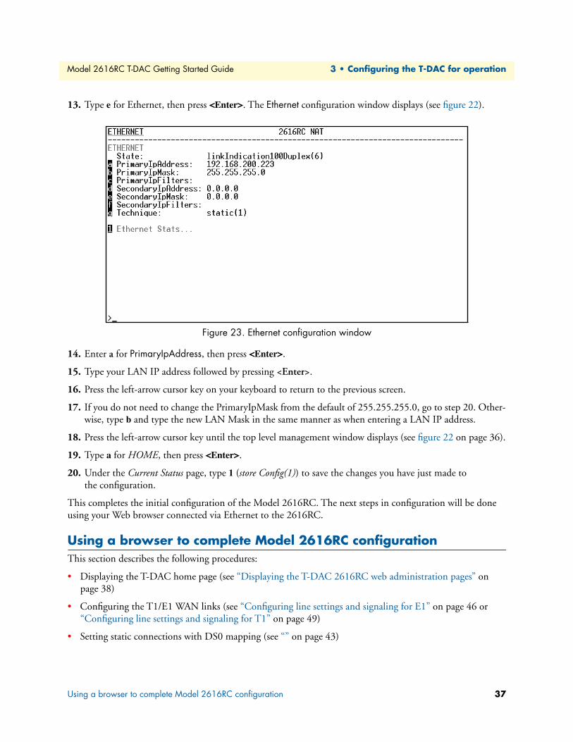
12. For the password, type superuser; the top level management window then appears (see figure 22).
Figure 22. VT-100 top level management window
Initial configuration through the RS-232 control port 36
Model 2616RC T-DAC Getting Started Guide 3 • Configuring the T-DAC for operation
13. Type e for Ethernet, then press <Enter>. The Ethernet configuration window displays (see figure 22).
Figure 23. Ethernet configuration window
14. Enter a for PrimaryIpAddress, then press <Enter>.
15. Type your LAN IP address followed by pressing <Enter>.
16. Press the left-arrow cursor key on your keyboard to return to the previous screen.
17. If you do not need to change the PrimaryIpMask from the default of 255.255.255.0, go to step 20. Other-wise, type b and type the new LAN Mask in the same manner as when entering a LAN IP address.
18. Press the left-arrow cursor key until the top level management window displays (see figure 22 on page 36).
19. Type a for HOME, then press <Enter>.
20. Under the Current Status page, type 1 (store Config(1)) to save the changes you have just made to the configuration.
This completes the initial configuration of the Model 2616RC. The next steps in configuration will be done using your Web browser connected via Ethernet to the 2616RC.
Using a browser to complete Model 2616RC configurationThis section describes the following procedures:
• Displaying the T-DAC home page (see “Displaying the T-DAC 2616RC web administration pages” on page 38)
• Configuring the T1/E1 WAN links (see “Configuring line settings and signaling for E1” on page 46 or “Configuring line settings and signaling for T1” on page 49)
• Setting static connections with DS0 mapping (see “” on page 43)
Using a browser to complete Model 2616RC configuration 37

Model 2616RC T-DAC Getting Started Guide 3 • Configuring the T-DAC for operation
• Setting the system clocking parameters (see “Configuring the system clocking parameters” on page 41)
• Configuring the IP default gateway (see “Configuring the default gateway” on page 40)
Displaying the T-DAC 2616RC web administration pagesDo the following:
1. Connect your PCs Ethernet connection to the Ethernet LAN.
2. Connect the 2616RC’s T-DAC 10/100 Ethernet connection to the Ethernet LAN.
3. At your PC, open a Web browser session. In your browser’s URL/address field type the IP address of the Model 2616RC (for example, if the Model 2616RC’s IP address 123.124.221.10, you would type 123.124.221.10 in the browser’s URL/address field). If you do not have an IP address in your TDAC, refer to “Initial configuration through the RS-232 control port” on page 33.
4. A login prompt will appear. In the username field type superuser then press <Tab> to move the cursor to the Password field. In the password field type superuser then press <Enter>.
5. The 2616RC Configuration Menu home page will appear (see figure 24).
Figure 24. 2616RC Configuration Menu home page
Home page overviewThe HOME window is divided into two panes: the Configuration Menu pane and the Configuration/informa-tion pane (see figure 25 on page 39). The Configuration Menu contains the links to the various Model 2616RC subsystems, while in the Configuration/information pane, you can view status and other information or make changes to the system configuration. Unlike the Configuration Menu pane, which appears the same no matter which subsystem page you may select, the Configuration/information pane contents will change as you move from one subsystem page to another.
Using a browser to complete Model 2616RC configuration 38

Model 2616RC T-DAC Getting Started Guide 3 • Configuring the T-DAC for operation
Figure 25. HOME page window panes
Figure 26. Operator Actions buttons
From the Home page, the following actions can be performed:
• Record Current Configuration—clicking on this button (see figure 26) saves the current configuration from volatile DRAM memory to FLASH memory. Once the configuration is saved into FLASH memory, the configuration will not be lost even if the power is cycled on the 2616RC. Initially, changes made to the 2616RC configuration are stored in volatile DRAM, enabling the user to set the box up with a working configuration before committing it to storage in FLASH. When you select Record Current Configuration, the 2616RC stores your changes to FLASH memory.
Note If you want to save the configuration changes that you have made, you must click on Record Current Configuration, otherwise all con-figuration changes will be lost if the power to the Model 2616RC is turned off.
Using a browser to complete Model 2616RC configuration 39

Model 2616RC T-DAC Getting Started Guide 3 • Configuring the T-DAC for operation
• Hard Reset—this button (see figure 26) causes the Model 2616RC to perform a cold restart. When you select Hard Reset, the T-DAC confirms that you want to execute this command. Then, the T-DAC will dis-connect all current sessions, re-initialize the interfaces, and re-load configuration parameters from FLASH.
• Set Factory Default Configuration—this button (see figure 26) clears out the configuration in FLASH and loads the factory default parameters into FLASH memory. The factory default settings will not execute on the Model 2616RC until it is re-booted by doing a Hard Reset.
Note Set Factory Default Configuration (figure 26) will delete any routing information, the Model 2616RC’s Ethernet IP address, and any other site-specific settings made for your particular installation. You will have to re-enter the Model 2616RC’s Ethernet IP address and net-mask using the rear panel control port before using the HTTP/HTML Management pages.
Configuring the default gatewayThe default gateway IP address, if defined, is used solely for managing the 2616RC remotely via the Ethernet port. The 2616RC does not transmit or receive user data nor any other traffic via the default gateway IP address or the Ethernet port.
Do the following to add the default gateway:
1. On the 2616RC Configuration Menu, click the IP hyperlink to open the IP Configuration page.
2. Click the Routing Info hyperlink to open the IP Routing Information page (figure 27).
Figure 27. IP Routing Information Page
3. The existing route you see in the table is the LAN IP address you assigned to the 2616RC during initial configuration through the RS-232 control port, earlier in this chapter.
4. To enter the default gateway, use the first Add a route line. The Destination shall remain 0.0.0.0, and there is no mask to enter.
5. In the Gateway box, type your default gateway IP address for the 2616RC.
Using a browser to complete Model 2616RC configuration 40

Model 2616RC T-DAC Getting Started Guide 3 • Configuring the T-DAC for operation
6. Click the Add Route button to save your configuration.
Figure 28. IP Routing Information window
7. The route which you already see in the table appeared upon the configuration of the LAN IP address.
8. To enter the default gateway, use the first Add Route line. The Destination shall remain as 0.0.0.0. There is no mask to enter.
9. Enter the IP address in the Gateway box. This is the default gateway.
10. Click on the Add Route button.
Configuring the system clocking parametersIn this section you will define clocking sources for the main reference and fallback reference on the 2616RC T-DAC. Clocking source selection will depend on the clocking role you assign to the blade: master(1), second-ary(2), or slave(3). The master will drive the main reference clock for the chassis. Should the master fail, the secondary will drive the main reference. Slaves will not drive any clock reference. Most often the 2616RC will be configured as slave(3), with another blade (such as the Patton Model 6511) configured as the master(1).
You can choose any one of the WAN ports, an internal oscillator, or system clock (provided by the ForeFront chassis). Unless it fails or becomes disconnected, the main reference provides the system clock for the 2616RC. Should this failure occur, the fallback reference will be the clocking source for the 2616RC’s system clock.
Example 1
Your 2616RC is the only blade in the chassis and must be configured as the system clocking master. This example assumes you will use T1/E1 port #1 as the main reference and T1/E1 port #2 as the fallback reference. To define the clocking source, do the following:
1. Connect a T1/E1 WAN line to WAN port #1 through the 2616RC’s WAN port cable.
2. Connect a T1/E1 WAN line to WAN port #2 through the 2616RC’s WAN port cable.
Using a browser to complete Model 2616RC configuration 41
Model 2616RC T-DAC Getting Started Guide 3 • Configuring the T-DAC for operation
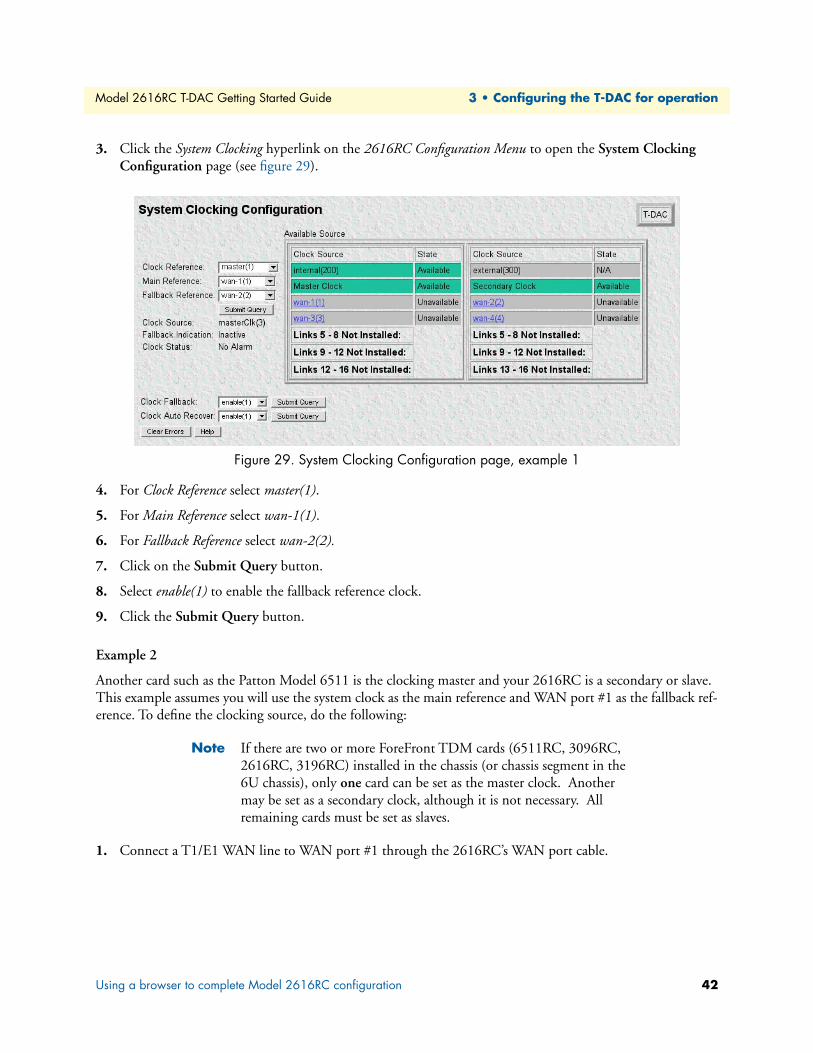
3. Click the System Clocking hyperlink on the 2616RC Configuration Menu to open the System Clocking Configuration page (see figure 29).
Figure 29. System Clocking Configuration page, example 1
4. For Clock Reference select master(1).
5. For Main Reference select wan-1(1).
6. For Fallback Reference select wan-2(2).
7. Click on the Submit Query button.
8. Select enable(1) to enable the fallback reference clock.
9. Click the Submit Query button.
Example 2
Another card such as the Patton Model 6511 is the clocking master and your 2616RC is a secondary or slave. This example assumes you will use the system clock as the main reference and WAN port #1 as the fallback ref-erence. To define the clocking source, do the following:
Note If there are two or more ForeFront TDM cards (6511RC, 3096RC, 2616RC, 3196RC) installed in the chassis (or chassis segment in the 6U chassis), only one card can be set as the master clock. Another may be set as a secondary clock, although it is not necessary. All remaining cards must be set as slaves.
1. Connect a T1/E1 WAN line to WAN port #1 through the 2616RC’s WAN port cable.
Using a browser to complete Model 2616RC configuration 42
Model 2616RC T-DAC Getting Started Guide 3 • Configuring the T-DAC for operation
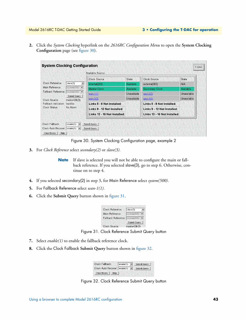
2. Click the System Clocking hyperlink on the 2616RC Configuration Menu to open the System Clocking Configuration page (see figure 30).
Figure 30. System Clocking Configuration page, example 2
3. For Clock Reference select secondary(2) or slave(3).
Note If slave is selected you will not be able to configure the main or fall-back reference. If you selected slave(3), go to step 6. Otherwise, con-tinue on to step 4.
4. If you selected secondary(2) in step 3, for Main Reference select system(500).
5. For Fallback Reference select wan-1(1).
6. Click the Submit Query button shown in figure 31.
Figure 31. Clock Reference Submit Query button
7. Select enable(1) to enable the fallback reference clock.
8. Click the Clock Fallback Submit Query button shown in figure 32.
Figure 32. Clock Reference Submit Query button
Using a browser to complete Model 2616RC configuration 43

Model 2616RC T-DAC Getting Started Guide 3 • Configuring the T-DAC for operation
Configuring the DS0 mappingYou need to make internal connections between a T1/E1 link and its destination. The destination of the T1/E1 link may be another T1/E1 port within the T-DAC, or the TDM bus in the chassis connecting to another T-DAC, DSL, or STM-1 card.
When configuring the 2616RC for T1/E1 cross connection the following scenarios may be encountered:
• Mapping DS0s from one E1/T1 port to another T1/E1 port on the same card. This is the simplest cross connection possible; DS0s are mapped from one T1/E1 port to another.
• Mapping DS0s from one E1/T1 port to another T1/E1 port on another card (or a DSL port on a Patton Model 3096RC) within the chassis. In this scenario, DS0s are first mapped from the originating 2616RC card T1/E1 port to a H.110 port (chassis TDM system bus). The destination card, similarly, must have a DS0 map from the H.110 bus to the appropriate T1/E1 port.
• Mapping DS0s from a T1/E1 port to an STM-1 card in the same chassis. In this scenario, the 2616RC first maps DS0s from a T1/E1 port to an H.110 port (TDM system bus). The system TDM bus, connected to all cards in the system, connects with a Patton 6511RC STM-1 card; DS0s are then placed into STM1 containers.
To define DS0 mapping for two T1/E1 ports, do the following:
1. On the Configuration Menu click DS0 Mapping hyperlink. The DS0 Mapping Overview window (see figure 33) displays.
Figure 33. DS0 Mapping Overview window
2. In the Display Option drop-down menu (see figure 34), select displayLongForm(0).
Figure 34. Display Option menu
Using a browser to complete Model 2616RC configuration 44

Model 2616RC T-DAC Getting Started Guide 3 • Configuring the T-DAC for operation
To define each DS0 Mapping you will create a static connection. “A” and “B” designate the two ends of the static connection. For each static connection you will define the following parameters:
– Device Type. Specifies the physical interface type for the connection. You may select either t1-e1 (1) or none(0). Additionally, for Device Type B, there is an option for toH.110(5) and fromH.110(6), indicat-ing direction of the T1/E1 DS0s mapped to the H.110 (TDM bus system).
– Device Number. Defines which T1/E1 port number on the 2616RC you are mapping. For example, to map a connection for T1/E1 port 3 you would select port3(3).
– Device Slots. Defines which DS0 channels will be mapped. Each DS0 channel is 64 kbps. Each T1port port has 24 DS0 channels. Each E1 WAN port has 32 DS0 channels. When defining time slots you must select the same number of Device Slots on the “A” and “B” sides of the connection. The slots are defined by entering a text string that represents the slots. For the T1/E1 ports, the slots that are available are 1–32. For a WAN port configured as a T1, the available slots are numbered from 1–24. For a WAN port configured as an E1, the available slots are 1–32. The H.110 (TDM system bus) is comprised of 32 ports; each port contains 128 unidirectional slots.
Examples for configuring static connections:
• Example 1: Connecting DS0s from an E1 port to another E1 port within one card.
• Example 2: Connecting DS0s from an E1 port on one card to an E1 port on another card via H.110 bus.
Example 1
Connect T1/E1 ports 1 and 10 to live E1 lines.
Solution:
1. Under Dev Type A, select t1-e1(1).
2. Under Dev Num A, select port1(1).
3. Under Dev Slots A, enter 1 - 32.
4. Under Dev Type B, select t1-e1(1).
5. Under Dev Num B, select port10(10).
6. Under Dev Slots B, enter 1 - 32.
7. Click the Submit Query button.
Example 2
Connect T1/E1 port 1 of card 1, and T1/E1 port 10 of card 2 to live E1 lines.
Solution:
Card one mapping
1. Under Dev Type A, select t1-e1(1).
2. Under Dev Num A, select port1(1).
3. Under Dev Slots A, enter 1 - 32.
4. Under Dev Type B, select toH110.
Using a browser to complete Model 2616RC configuration 45
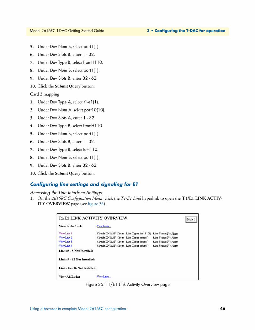
Model 2616RC T-DAC Getting Started Guide 3 • Configuring the T-DAC for operation
5. Under Dev Num B, select port1(1).
6. Under Dev Slots B, enter 1 - 32.
7. Under Dev Type B, select fromH110.
8. Under Dev Num B, select port1(1).
9. Under Dev Slots B, enter 32 - 62.
10. Click the Submit Query button.
Card 2 mapping
1. Under Dev Type A, select t1-e1(1).
2. Under Dev Num A, select port10(10).
3. Under Dev Slots A, enter 1 - 32.
4. Under Dev Type B, select fromH110.
5. Under Dev Num B, select port1(1).
6. Under Dev Slots B, enter 1 - 32.
7. Under Dev Type B, select toH110.
8. Under Dev Num B, select port1(1).
9. Under Dev Slots B, enter 32 - 62.
10. Click the Submit Query button.
Configuring line settings and signaling for E1
Accessing the Line Interface Settings1. On the 2616RC Configuration Menu, click the T1/E1 Link hyperlink to open the T1/E1 LINK ACTIV-
ITY OVERVIEW page (see figure 35).
Figure 35. T1/E1 Link Activity Overview page
Using a browser to complete Model 2616RC configuration 46
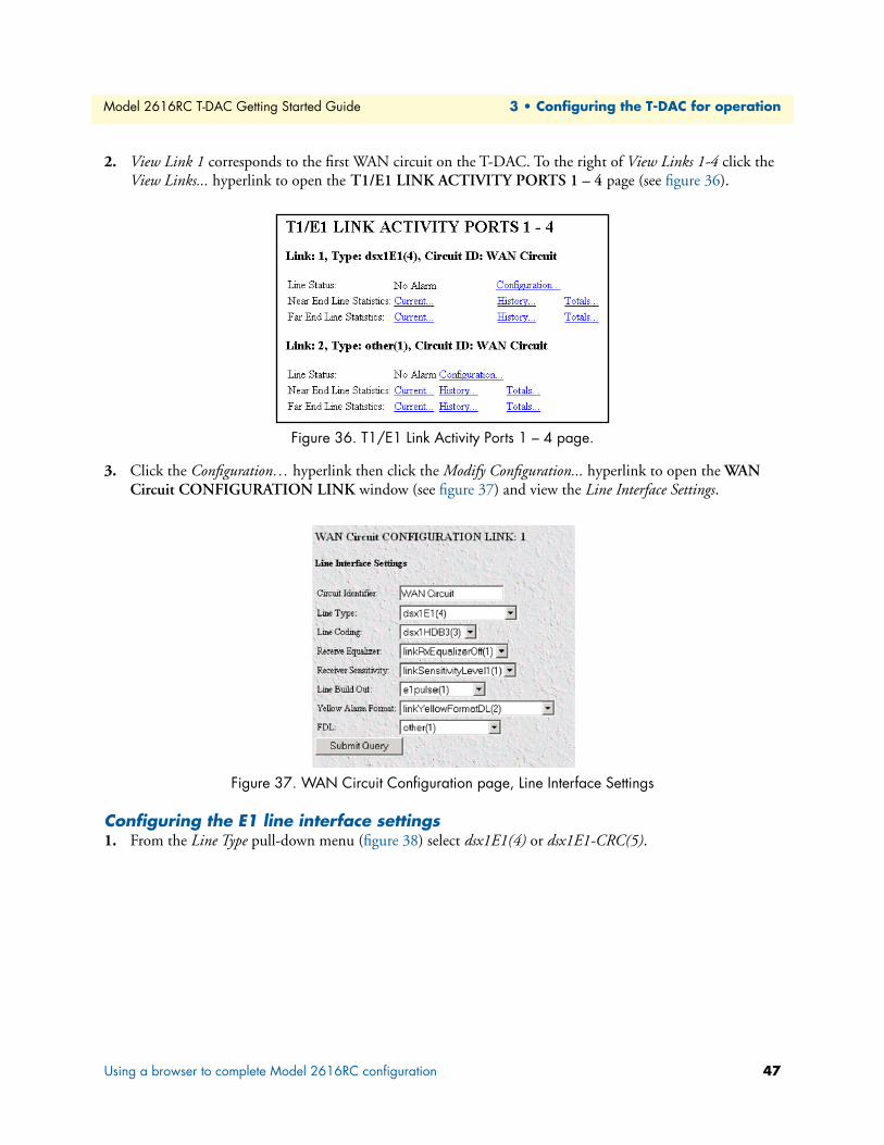
Model 2616RC T-DAC Getting Started Guide 3 • Configuring the T-DAC for operation
2. View Link 1 corresponds to the first WAN circuit on the T-DAC. To the right of View Links 1-4 click the View Links... hyperlink to open the T1/E1 LINK ACTIVITY PORTS 1 – 4 page (see figure 36).
Figure 36. T1/E1 Link Activity Ports 1 – 4 page.
3. Click the Configuration… hyperlink then click the Modify Configuration... hyperlink to open the WAN Circuit CONFIGURATION LINK window (see figure 37) and view the Line Interface Settings.
Figure 37. WAN Circuit Configuration page, Line Interface Settings
Configuring the E1 line interface settings1. From the Line Type pull-down menu (figure 38) select dsx1E1(4) or dsx1E1-CRC(5).
Using a browser to complete Model 2616RC configuration 47
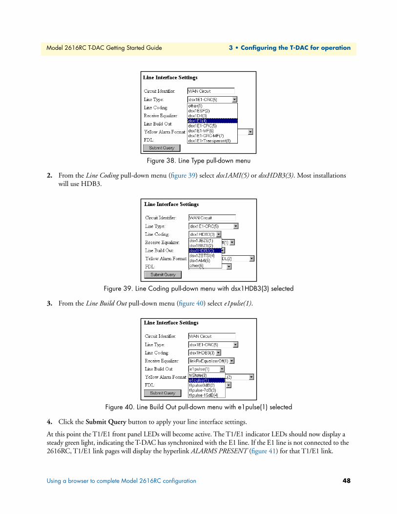
Model 2616RC T-DAC Getting Started Guide 3 • Configuring the T-DAC for operation
Figure 38. Line Type pull-down menu
2. From the Line Coding pull-down menu (figure 39) select dsx1AMI(5) or dsxHDB3(3). Most installations will use HDB3.
Figure 39. Line Coding pull-down menu with dsx1HDB3(3) selected
3. From the Line Build Out pull-down menu (figure 40) select e1pulse(1).
Figure 40. Line Build Out pull-down menu with e1pulse(1) selected
4. Click the Submit Query button to apply your line interface settings.
At this point the T1/E1 front panel LEDs will become active. The T1/E1 indicator LEDs should now display a steady green light, indicating the T-DAC has synchronized with the E1 line. If the E1 line is not connected to the 2616RC, T1/E1 link pages will display the hyperlink ALARMS PRESENT (figure 41) for that T1/E1 link.
Using a browser to complete Model 2616RC configuration 48

Model 2616RC T-DAC Getting Started Guide 3 • Configuring the T-DAC for operation
Figure 41. E1 ALARMS PRESENT indicator
After you connect the E1 line to the WAN port on the rear of the Model 2616RC these alarms should disappear.
Configuring line settings and signaling for T1
Accessing the Line Interface Settings1. On the 2616RC Configuration Menu, click the T1/E1 Link hyperlink to open the T1/E1 LINK ACTIV-
ITY OVERVIEW page (figure 42).
Figure 42. T1/E1 Link Activity Overview page
2. View Link 1 corresponds to the first WAN circuit on the T-DAC. To the right of View Links 1-4 click the View Links... hyperlink to open the T1/E1 LINK ACTIVITY PORTS 1 – 4 page (figure 43).
Figure 43. T1/E1 Link Activity Ports 1 – 4 page.
Using a browser to complete Model 2616RC configuration 49

Model 2616RC T-DAC Getting Started Guide 3 • Configuring the T-DAC for operation
3. Click the Configuration… hyperlink, then click the Modify Configuration... hyperlink to open the WAN Circuit CONFIGURATION LINK window (figure 44) and view the Line Interface Settings.
Figure 44. WAN Circuit Configuration page, Line Interface Settings
Configuring the T1 line settings1. From the Line Type pull-down menu (figure 45) select either:
– dsx1ESF(2) - indicates Extended SuperFrame DS1
– dsx1D4 - indicates AT&T D4 format DS1
Figure 45. Line Type pull-down menu with dsx1ESF(2) selected
Using a browser to complete Model 2616RC configuration 50
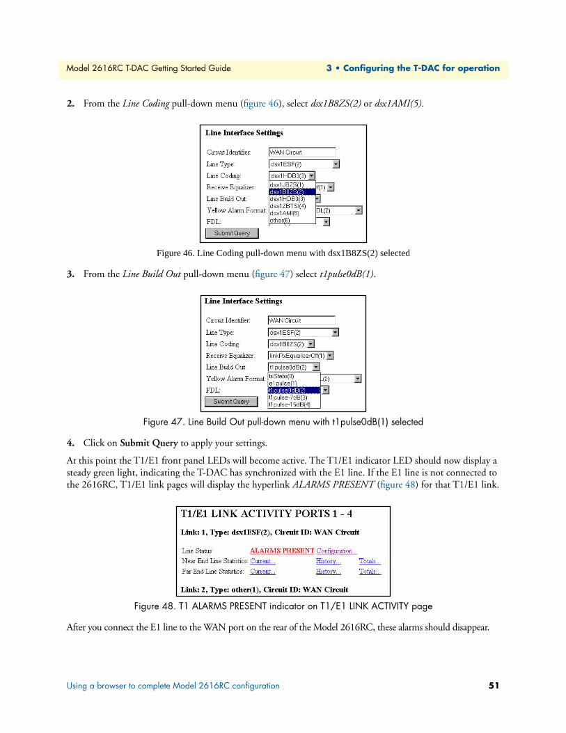
Model 2616RC T-DAC Getting Started Guide 3 • Configuring the T-DAC for operation
2. From the Line Coding pull-down menu (figure 46), select dsx1B8ZS(2) or dsx1AMI(5).
Figure 46. Line Coding pull-down menu with dsx1B8ZS(2) selected
3. From the Line Build Out pull-down menu (figure 47) select t1pulse0dB(1).
Figure 47. Line Build Out pull-down menu with t1pulse0dB(1) selected
4. Click on Submit Query to apply your settings.
At this point the T1/E1 front panel LEDs will become active. The T1/E1 indicator LED should now display a steady green light, indicating the T-DAC has synchronized with the E1 line. If the E1 line is not connected to the 2616RC, T1/E1 link pages will display the hyperlink ALARMS PRESENT (figure 48) for that T1/E1 link.
Figure 48. T1 ALARMS PRESENT indicator on T1/E1 LINK ACTIVITY page
After you connect the E1 line to the WAN port on the rear of the Model 2616RC, these alarms should disappear.
Using a browser to complete Model 2616RC configuration 51

Model 2616RC T-DAC Getting Started Guide 3 • Configuring the T-DAC for operation
Enabling/disabling the alarm cardThe Alarm Card window (see figure 49) is where you can configure the alarm card polling mode to determine whether the 2616RC monitors the alarm card status for the chassis.
1. Click on Alarm Card under the configuration menu to display the Alarm Card Information window.
2. From the Alarm Card Polling Mode menu, select an option from the drop-down menu to enable/disable the alarm card.
– doNotMonitor(0)—Disables the alarm card
– monitorAlarmCard(1)—Enables the alarm card
3. Click Submit to save the change.
Note If the chassis contains more than one (2616RC/3096RC/3196RC) or any combination thereof, then only one card should be enabled to monitor the alarm card.
Figure 49. Alarm Card Information window
Using a browser to complete Model 2616RC configuration 52

Model 2616RC T-DAC Getting Started Guide 3 • Configuring the T-DAC for operation
Saving your configurationAt this point you have completed the basic configuration of your T-DAC for operation. To save your configu-ration settings in non-volatile RAM, do the following:
1. On the Configuration Menu click the Select HOME hyperlink to open the 2616RC Configuration Menu home page (figure 50).
Figure 50. 2616RC Configuration Menu home page
2. Click the Record Current Configuration button (see figure 50).
Note All configuration settings will be lost unless you click on the Record Cur-rent Configuration button before you power down or reset the T-DAC.
Backing up your configuration parametersThe 2616RC T-DAC provides Import/Export functions. These functions enable you to back up (export) and restore (import) your T-DAC’s configuration parameters against possible failure. Should your T-DAC ever need replacing, a previously saved copy of your (exported) configuration file can quickly be loaded (imported) into a replacement T-DAC.
Note Import/Export functions require superuser access privileges.
Note The parameters that will be exported are the power-up settings as they are stored in flash memory and may not be the current operating parameters. To ensure that you export the most current parameters, go to HOME, then under Operator Actions, click on the Record Cur-rent Configuration button.
Saving your configuration 53
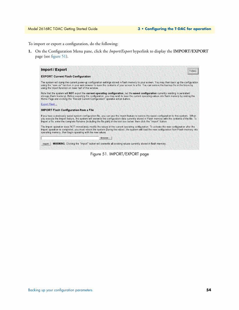
Model 2616RC T-DAC Getting Started Guide 3 • Configuring the T-DAC for operation
To import or export a configuration, do the following:
1. On the Configuration Menu pane, click the Import/Export hyperlink to display the IMPORT/EXPORT page (see figure 51).
Figure 51. IMPORT/EXPORT page
Backing up your configuration parameters 54

Model 2616RC T-DAC Getting Started Guide 3 • Configuring the T-DAC for operation
Backing up the configuration store in flash memory1. To make a back-up copy of the configuration file currently stored in your T-DAC’s flash memory:
– On the Import/Export page (figure 52) click the Export Flash... hyperlink. The T-DAC will get the con-figuration file currently stored in your T-DAC’s flash memory and display it in your browser (figure 52)
Figure 52. Example T-DAC flash memory configuration file displayed in a browser
Backing up your configuration parameters 55
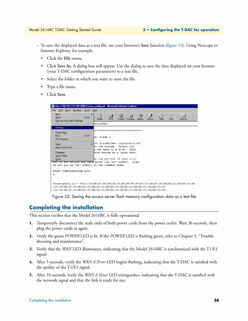
Model 2616RC T-DAC Getting Started Guide 3 • Configuring the T-DAC for operation
– To save the displayed data as a text file, use your browser’s Save function (figure 53). Using Netscape or Internet Explorer, for example.
• Click the File menu.
• Click Save As. A dialog box will appear. Use the dialog to save the data displayed on your browser (your T-DAC configuration parameters) to a text file.
• Select the folder in which you want to store the file.
• Type a file name.
• Click Save.
Figure 53. Saving the access server flash memory configuration data as a text file
Completing the installationThis section verifies that the Model 2616RC is fully operational.
1. Temporarily disconnect the male ends of both power cords from the power outlet. Wait 30 seconds, then plug the power cords in again.
2. Verify the green POWER LED is lit. If the POWER LED is flashing green, refer to Chapter 5, “Trouble-shooting and maintenance”.
3. Verify that the WAN LED illuminates, indicating that the Model 2616RC is synchronized with the T1/E1 signal.
4. After 5 seconds, verify the WAN A Error LED begins flashing, indicating that the T-DAC is satisfied with the quality of the T1/E1 signal.
5. After 10 seconds, verify the WAN A Error LED extinguishes, indicating that the T-DAC is satisfied with the network signal and that the link is ready for use.
Completing the installation 56
Model 2616RC T-DAC Getting Started Guide 3 • Configuring the T-DAC for operation
Note If the T-DAC does not behave as described, the most likely cause is that the T-DAC default settings are not compatible with the T1/E1 line. If this is the case, use the RS-232 CONFIG port to correct the T-DAC settings. You will have to use the 2616RC Configuration Menu pages to examine the configured T1/E1 link settings.
6. There are two LEDs that indicate the status of the T-DAC 10/100 Ethernet port: a green LED indicates link status and activity, and a yellow LED that indicates line speed. Verify that the green LED is either flashing green (meaning that packets are being received at the Ethernet port) or solid green (meaning that the link is valid but no packets are being received).
Congratulations! Your T-DAC is now installed. If you require further information about configuring your T-DAC settings, refer to the DSL T-DAC Administrator’s Reference Guide included on your Model 2616RC CD-ROM.
Note For information on activating and de-activating your Model 2616RC T-DAC, refer to Chapter 4, “Operation and shutdown”
Completing the installation 57

Chapter 4 Operation and shutdown
Chapter contentsIntroduction ..........................................................................................................................................................59Activating the Model 2616RC...............................................................................................................................59De-activating the Model 2616RC..........................................................................................................................59
58

Model 2616RC T-DAC Getting Started Guide 4 • Operation and shutdown
IntroductionThis chapter describes how to start up and power down the Model 2616RC.
Activating the Model 2616RCThe Model 2616RC is activated by completing the procedures in Chapter 2, “Hardware installation” and Chapter 3, “Configuring the T-DAC for operation”. To activate the 2616RC, please follow the procedures in those chapters.
The Model 2616RC is designed for unattended operation.Once the Model 2616RC has been installed and configured, no further operator action is required under normal conditions.
De-activating the Model 2616RCPerform the following procedure to deactivate the Model 2616RC.
Note Be sure to wear an anti-static strap to prevent electrostatic damage to the blade.
1. Unlock the handles on the front of the 2616RC by pressing the red button on each handle. The button immediately activates the switch (turning it to an open position), while the button itself remains depressed. Remove the blade by pushing the handles outwards.
2. Remove the Model 2616RC from the rack chassis. Place the blade on an anti-static surface.
3. Remove the rear blade from the rack chassis. Place the blade on an anti-static surface.
Introduction 59
Chapter 5 Troubleshooting and maintenance
Chapter contentsIntroduction ..........................................................................................................................................................61Fault analysis .........................................................................................................................................................62T1/E1 port test modes...........................................................................................................................................64
DSX1 payload loop (dsx1PayloadLoop) ..........................................................................................................64DSX1 line loop (dsxLineLoop) .......................................................................................................................65
Periodic maintenance ............................................................................................................................................66Calibration ......................................................................................................................................................66
Maintenance..........................................................................................................................................................66Exporting the current Model 2616RC configuration ......................................................................................66
Removing the defective Model 2616RC ....................................................................................................69Installing the replacement Model 2616RC ................................................................................................70Importing a saved configuration ................................................................................................................70Completing the installation .......................................................................................................................71
60

Model 2616RC T-DAC Getting Started Guide 5 • Troubleshooting and maintenance
IntroductionThis chapter describes troubleshooting and fault analysis that can be performed by the operator. If you require more help, refer to Chapter 6, “Contacting Patton for assistance”. Refer to table 6 for a list of common symp-toms and suggested remedies.
Note The following information assumes that there is only one failure involving the Model 2616RC and that if you perform the corrective action listed, it will solve the problem. If you are unable to correct a failure, refer to Chapter 6, “Contacting Patton for assistance”.
Note When removing the 2616RC from the chassis, follow the procedures cited in “De-activating the Model 2616RC” on page 59.
Note When re-inserting the 2616RC into the chassis, please follow the pro-cedures cited in “T-DAC blades installation” on page 20.
Table 6. Symptoms
Problem Corrective Action
POWER LED (green)is extinguished
To verify that power is being supplied to the Model 2616RC via the Patton ForeFront chassis power bus: verify that at least one chassis power supply module is installed in the chassis and functioning normally.
POWER LED (green) is flashing
The 2616RC has detected a power failure on a power bus. There may be a problem with the Patton ForeFront chassis power system which feeds the Model 2616RC such as a failed power supply module in the chassis. The Model 2616RC will function normally with one power supply. Inspect the power supplies in the Patton ForeFront chassis to identify and replace the failed power supply module. If no failed power supply is found, or if the POWER LED continues flashing, contact Patton Technical Support to determine if the T-DAC should be replaced.
CPU FAIL LED (red) is lit CPU is unable to load the software from FLASH to RAM for operation. As soon as possible, remove the Model 2616RC from the Patton ForeFront chassis, wait 30 seconds, then re-insert the Model 2616RC into the Patton ForeFront chassis and see if the problem disap-pears. If the CPU FAIL LED remains lit after the Model 2616RC completes the power-up cycle, contact Patton Technical Support to determine if the T-DAC needs to be replaced.
ALARM LED (yellow) is lit
Indicates The 2616RC has detected a minor or major alarm condition.
SYSTEM LED (green) is not flashing
The Model 2616RC is not functioning properly. As soon as possible, remove the Model 2616RC from the Patton ForeFront chassis, wait 30 seconds, then re-insert the Model 2616RC into the Patton ForeFront chassis and see if the problem disappears. If the SYSTEM LED remains lit after the Model 2616RC completes the power-up cycle, contact Patton Tech-nical Support to determine if the T-DAC needs to be replaced.
ETHERNET LED (green) is extinguished
• A valid Ethernet link has not been detected. Verify that the Model 2616RC is connected by means of an Ethernet cable to an Ethernet hub, switch, or workstation and that both ends of the cable are plugged in.
• Verify that the hub, switch, or workstation is powered on.
• Verify that the correct cable is being used—either a straight through or cross-over cable depending on whether you are connecting to a workstation (PC), hub, or switch.
• Replace the Ethernet cable. If the problem still exists, contact Patton Technical Support to determine if the T-DAC should be replaced.
Introduction 61

Model 2616RC T-DAC Getting Started Guide 5 • Troubleshooting and maintenance
Fault analysisThe following procedures outline steps you should follow when troubleshooting a Model 2616RC malfunction.
1. If possible, talk to the person who filed the trouble complaint and determine the operational symptoms. Record the symptoms on the appropriate trouble report form (include the front panel LED indications).
2. Refer to table 7 for LED definitions and compare the recorded results from the trouble report against those in the table, then refer to the section recommended in the table for the maintenance procedure that will repair the malfunction.
Table 7. LED definitions
LED Location Color Status Meaning
POWER Front panel
Green On solid
Power is being applied. No action recommended.
Flashing The 2616RC has detected a power failure on a power bus. There may be a problem with the Patton ForeFront chassis power sup-ply system such as a failed power supply module in the chassis. The Model 2616RC will function normally with one power sup-ply. Inspect the power supplies in the Patton ForeFront chassis to identify and replace the failed power supply module. If the POWER LED continues flashing when all chassis power supplies are functional, contact Patton Technical Support to determine if the T-DAC should be replaced.
Off No input power is being applied. Verify that at least one chas-sis power supply module is installed in the chassis and func-tioning normally.
CPU FAIL Front panel
Red On solid
CPU is unable to load the software from FLASH to RAM for operation. As soon as possible, remove the Model 2616RC from the Patton ForeFront chassis, wait 30 seconds, then re-insert the Model 2616RC into the Patton ForeFront chassis and see if the problem disappears. If the CPU FAIL LED remains lit after the Model 2616RC completes the power-up cycle, contact Patton Technical Support to determine if the T-DAC needs to be replaced.
Off The CPU is operating normally. No action recommended.ALARM Front
panelRed On
solidA minor alarm condition has been detected.
Flash-ing
A major alarm condition has been detected.
Off The Model 2616RC is operating normally. No action rec-ommended.
Fault analysis 62
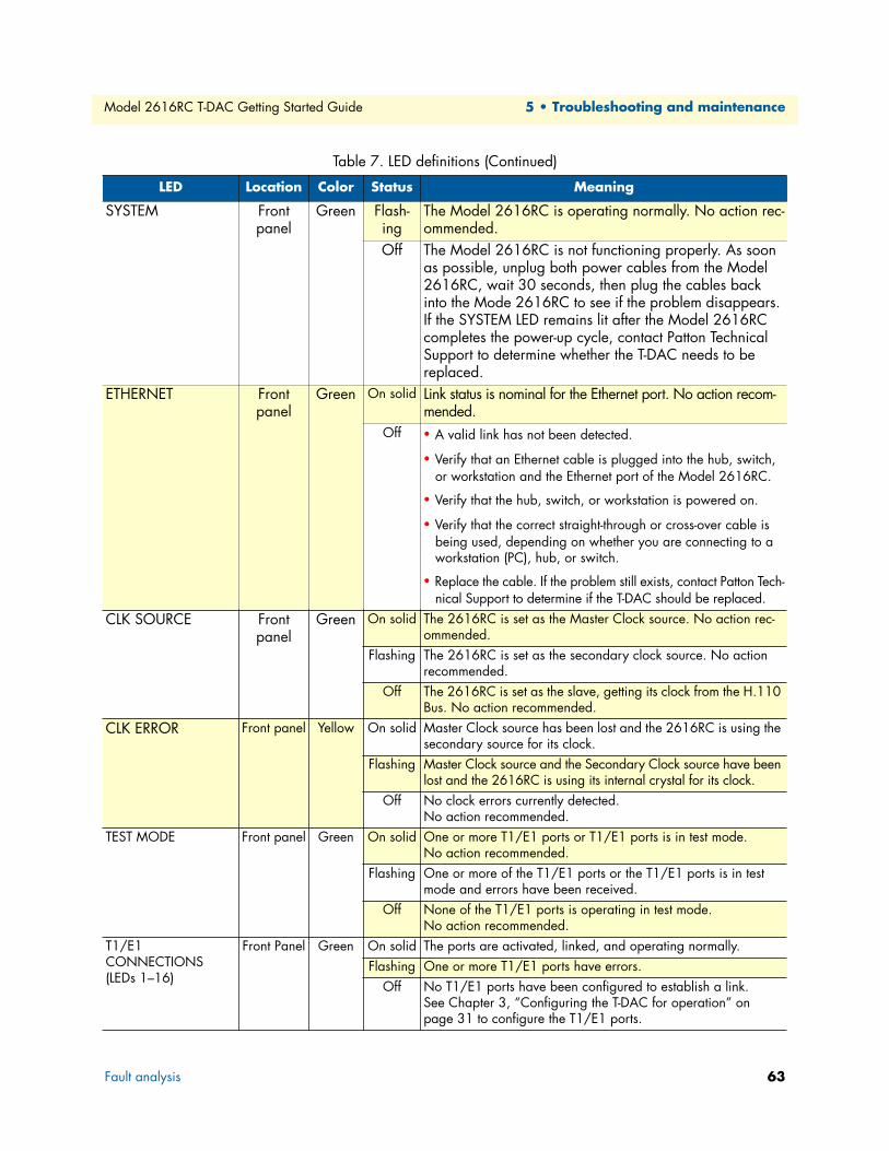
Model 2616RC T-DAC Getting Started Guide 5 • Troubleshooting and maintenance
SYSTEM Front panel
Green Flash-ing
The Model 2616RC is operating normally. No action rec-ommended.
Off The Model 2616RC is not functioning properly. As soon as possible, unplug both power cables from the Model 2616RC, wait 30 seconds, then plug the cables back into the Mode 2616RC to see if the problem disappears. If the SYSTEM LED remains lit after the Model 2616RC completes the power-up cycle, contact Patton Technical Support to determine whether the T-DAC needs to be replaced.
ETHERNET Front panel
Green On solid Link status is nominal for the Ethernet port. No action recom-mended.
Off • A valid link has not been detected.
• Verify that an Ethernet cable is plugged into the hub, switch, or workstation and the Ethernet port of the Model 2616RC.
• Verify that the hub, switch, or workstation is powered on.
• Verify that the correct straight-through or cross-over cable is being used, depending on whether you are connecting to a workstation (PC), hub, or switch.
• Replace the cable. If the problem still exists, contact Patton Tech-nical Support to determine if the T-DAC should be replaced.
CLK SOURCE Front panel
Green On solid The 2616RC is set as the Master Clock source. No action rec-ommended.
Flashing The 2616RC is set as the secondary clock source. No action recommended.
Off The 2616RC is set as the slave, getting its clock from the H.110 Bus. No action recommended.
CLK ERROR Front panel Yellow On solid Master Clock source has been lost and the 2616RC is using the secondary source for its clock.
Flashing Master Clock source and the Secondary Clock source have been lost and the 2616RC is using its internal crystal for its clock.
Off No clock errors currently detected. No action recommended.
TEST MODE Front panel Green On solid One or more T1/E1 ports or T1/E1 ports is in test mode.No action recommended.
Flashing One or more of the T1/E1 ports or the T1/E1 ports is in test mode and errors have been received.
Off None of the T1/E1 ports is operating in test mode. No action recommended.
T1/E1 CONNECTIONS(LEDs 1–16)
Front Panel Green On solid The ports are activated, linked, and operating normally.Flashing One or more T1/E1 ports have errors.
Off No T1/E1 ports have been configured to establish a link.See Chapter 3, “Configuring the T-DAC for operation” on page 31 to configure the T1/E1 ports.
Table 7. LED definitions (Continued)
LED Location Color Status Meaning
Fault analysis 63

Model 2616RC T-DAC Getting Started Guide 5 • Troubleshooting and maintenance
T1/E1 port test modesThe 2616RC offers a number of diagnostics tools to test operation and performance of the T1/E1 ports and line. Diagnostics include DSX1 payload loop and DSX1 line loop.
DSX1 payload loop (dsx1PayloadLoop)When activated, the received signal at the selected T1/E1 port, will be looped through the 2616RC (see figure 54). Typically the received signal is looped back for retransmission after it has passed through the device's framing function (framing is terminated and then regenerated).
Figure 54. Payload loopback
To activate payload loop, do the following:
1. Click on the Modify Configuration link of the T1/E1 port to be placed under test
2. Locate the Loopback Configuration drop down menu
3. Select Payload Loop and click on the Submit Query button on the right.
To deactivate payload loop, set the Loopback Configuration drop down menu to NoLoop.
READY Front panel Blue On Card ready for removal from Patton ForeFront chassis.Off Card not ready for removal from Patton ForeFront chassis.
Do not remove card from chassis.ALARM Rear blade Yellow On solid A minor alarm condition has been detected.
Flashing A major alarm condition has been detected.Off The Model 2616RC is operating normally. No action
recommended.READY Rear blade Blue On Card ready for removal from Patton ForeFront chassis.
Off Card not ready for removal from Patton ForeFront chassis. Do not remove card from chassis.
Table 7. LED definitions (Continued)
LED Location Color Status Meaning
T1/E1 port test modes 64
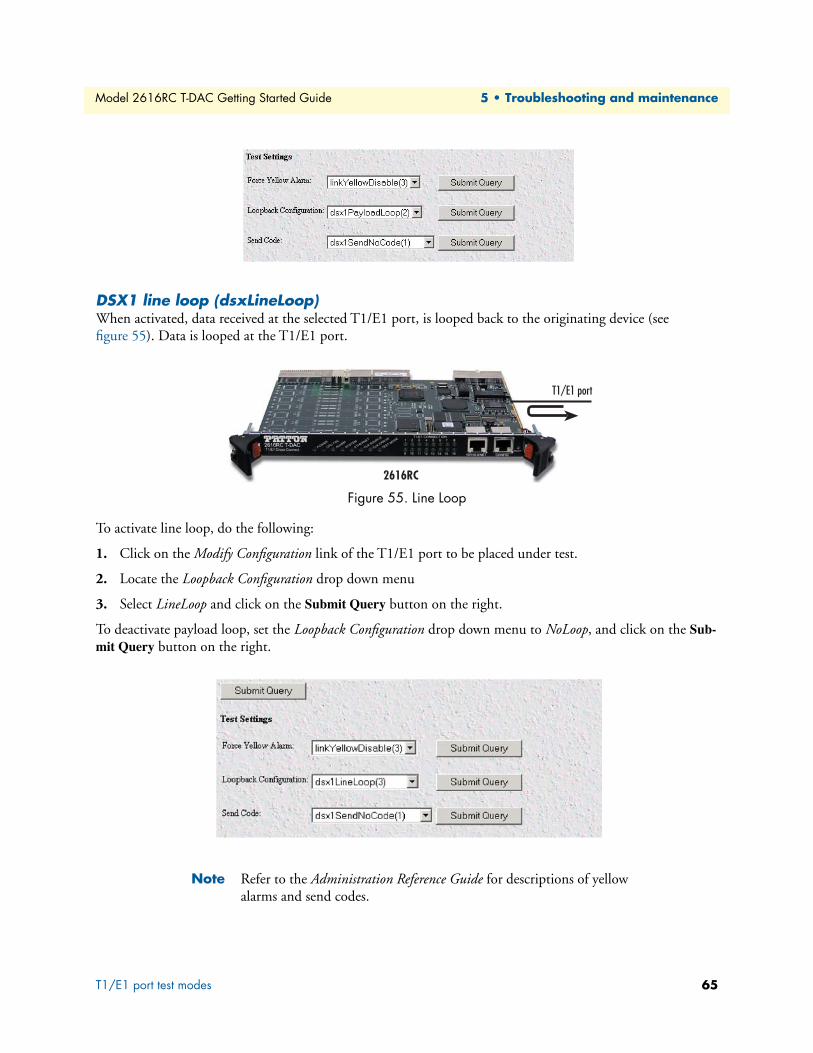
Model 2616RC T-DAC Getting Started Guide 5 • Troubleshooting and maintenance
DSX1 line loop (dsxLineLoop)When activated, data received at the selected T1/E1 port, is looped back to the originating device (see figure 55). Data is looped at the T1/E1 port.
Figure 55. Line Loop
To activate line loop, do the following:
1. Click on the Modify Configuration link of the T1/E1 port to be placed under test.
2. Locate the Loopback Configuration drop down menu
3. Select LineLoop and click on the Submit Query button on the right.
To deactivate payload loop, set the Loopback Configuration drop down menu to NoLoop, and click on the Sub-mit Query button on the right.
Note Refer to the Administration Reference Guide for descriptions of yellow alarms and send codes.
T1/E1 port test modes 65

Model 2616RC T-DAC Getting Started Guide 5 • Troubleshooting and maintenance
Periodic maintenanceConsult the rack chassis user manual for information on preventative maintenance (such as cleaning the chassis air cooling vents to remove accumulated dust).
CalibrationThe Model 2616RC requires no calibration.
MaintenanceIf you isolate a problem to the a Model 2616RC component, the entire Model 2616RC must be replaced as follows.
Exporting the current Model 2616RC configurationThe 2616RC T-DAC provides Import/Export functions. These functions enable you to back up (export) and restore (import) your T-DAC’s configuration parameters against possible failure. Should your T-DAC ever need replacing, a previously saved copy of your (exported) configuration file can quickly be loaded (imported) into a replacement T-DAC.
Note Import/Export functions require superuser access privileges.
Note The parameters that will be exported are the power-up settings as they are stored in flash memory and may not be the current operating parameters. To ensure that you export the most current parameters, go to HOME, then under Operator Actions, click on the Record Current Configuration button.
1. If you already have an exported backup copy of your current configuration, go to “Removing the defective Model 2616RC” on page 69. Otherwise, go to step 2.
2. On the Configuration Menu pane, click the Import/Export hyperlink to display the Import/Export page (figure 56).
Periodic maintenance 66

Model 2616RC T-DAC Getting Started Guide 5 • Troubleshooting and maintenance
Figure 56. IMPORT/EXPORT page
Maintenance 67

Model 2616RC T-DAC Getting Started Guide 5 • Troubleshooting and maintenance
3. To make a back-up copy of the configuration file currently stored in your T-DAC’s flash memory:
– On the Import/Export page (figure 56 on page 67) click the Export Flash... hyperlink. The T-DAC will get the configuration file currently stored in your T-DAC’s flash memory and display it in your browser (figure 57)
Figure 57. Example T-DAC flash memory configuration file displayed in a browser
Maintenance 68
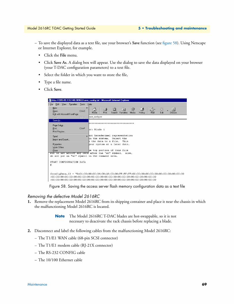
Model 2616RC T-DAC Getting Started Guide 5 • Troubleshooting and maintenance
– To save the displayed data as a text file, use your browser’s Save function (see figure 58). Using Netscape or Internet Explorer, for example.
• Click the File menu.
• Click Save As. A dialog box will appear. Use the dialog to save the data displayed on your browser (your T-DAC configuration parameters) to a text file.
• Select the folder in which you want to store the file,
• Type a file name.
• Click Save.
Figure 58. Saving the access server flash memory configuration data as a text file
Removing the defective Model 2616RC1. Remove the replacement Model 2616RC from its shipping container and place it near the chassis in which
the malfunctioning Model 2616RC is located.
Note The Model 2616RC T-DAC blades are hot-swappable, so it is not necessary to deactivate the rack chassis before replacing a blade.
2. Disconnect and label the following cables from the malfunctioning Model 2616RC:
– The T1/E1 WAN cable (68-pin SCSI connector)
– The T1/E1 modem cable (RJ-21X connector)
– The RS-232 CONFIG cable
– The 10/100 Ethernet cable
Maintenance 69

Model 2616RC T-DAC Getting Started Guide 5 • Troubleshooting and maintenance
3. Unlock the handles by pressing the red button on each handle. The button immediately activates the switch (turning it to an open position), while the button itself remains depressed. The blade can then be removed.
4. Remove the malfunctioning Model 2616RC by pushing the handles outwards, pulling the card gently but firmly from its slot in the chassis. Place the removed card in the container the replacement Model 2616RC came in so you can return the defective Model 2616RC for repair.
Installing the replacement Model 2616RC1. Insert the replacement Model 2616RC into the rack chassis.
2. Insert the rear blade into the desired slot in the rack chassis. Make sure the blade is seated properly in the slot guides.
3. Gently press the blade into the chassis until the alignment/ESD pin engages the chassis. When the blade is fully seated, the red buttons in the handles click up automatically, thus locking the handle and activating the switch (closed position). The click of the button gives a visual and audible confirmation that the board is fully seated.
4. Connect the following cables to the Model 2616RC:
– The T1/E1 WAN cable (68-pin SCSI connector)
– The RS-232 CONFIG cable
– The 10/100 ETHERNET cable
5. Verify that the green POWER LED is lit.
Importing a saved configurationBefore importing a saved configuration, you must define the Model 2616RC’s IP address and netmask. These parameters are defined via the Model 2616RC RS-232 CONFIG port on the Model 2616RC.
1. Refer to Chapter 3, “Configuring the T-DAC for operation” and follow the procedures contained in sec-tion “Initial configuration through the RS-232 control port” on page 33.
2. To import a saved configuration, connect your Web browser to the Administration Pages, then click on Import/Export under the Configuration Menu to display the Import/Export page (figure 56 on page 67).
3. To import a configuration file into the Model 2616RC, type the complete path and filename for the con-figuration file you wish to load or click on the Browse… button to select the desired file, then click the Submit Query button.
Upon successfully importing the file, the Model 2616RC will display Configuration Load Complete, indi-cating that the new operating parameters have been loaded into flash memory.
4. On the Configuration Menu, click the HOME hyperlink, then click the Hard Reset button under Opera-tor Actions.
Note Do not select Record Current Configuration after importing config-uration parameters.
Maintenance 70

Model 2616RC T-DAC Getting Started Guide 5 • Troubleshooting and maintenance
Completing the installationThis section verifies that the Model 2616RC is fully operational.
1. Verify that the green POWER LED is lit. If the POWER LED is flashing green, refer to Chapter 5, “Trou-bleshooting and maintenance” on page 60.
2. Verify that the WAN LED illuminates, indicating that the Model 2616RC is synchronizing with the T1/E1 signal.
3. Verify that after 5 seconds, the WAN LED begins flashing, indicating that the Model 2616RC is satisfied with the quality of the T1/E1 signal.
4. Verify that after 10 seconds, the WAN LED extinguishes, indicating that the Model 2616RC is satisfied with the network signal and that the link is ready for use.
5. Verify that the green Ethernet LED is either flashing (indicating link status is nominal for the front Ether-net port) or on solid (indicating that link status is nominal for at least one of the Ethernet backplane con-nections).
The Model 2616RC is operational.
Maintenance 71
Chapter 6 Contacting Patton for assistance
Chapter contentsIntroduction ..........................................................................................................................................................73Contact information..............................................................................................................................................73Warranty Service and Returned Merchandise Authorizations (RMAs)...................................................................73
Warranty coverage ..........................................................................................................................................73Out-of-warranty service .............................................................................................................................73Returns for credit ......................................................................................................................................73Return for credit policy .............................................................................................................................74
RMA numbers ................................................................................................................................................74Shipping instructions ................................................................................................................................74
72

Model 2616RC T-DAC Getting Started Guide 6 • Contacting Patton for assistance
IntroductionThis chapter contains the following information:
• “Contact information”—describes how to contact PATTON technical support for assistance.
• “Warranty Service and Returned Merchandise Authorizations (RMAs)”—contains information about the RAS warranty and obtaining a return merchandise authorization (RMA).
Contact informationPatton Electronics offers a wide array of free technical services. If you have questions about any of our other products we recommend you begin your search for answers by using our technical knowledge base. Here, we have gathered together many of the more commonly asked questions and compiled them into a searchable database to help you quickly solve your problems.
• Online support—available at www.patton.com.
• E-mail support—e-mail sent to [email protected] will be answered within 1 business day
• Telephone support—standard telephone support is available Monday through Friday, from 8:00 A.M. to 5:00 P.M. EST (8:00 to 17:00 UTC-5), Monday through Friday by calling +1 (301) 975-1007
Warranty Service and Returned Merchandise Authorizations (RMAs)Patton Electronics is an ISO-9001 certified manufacturer and our products are carefully tested before ship-ment. All of our products are backed by a comprehensive warranty program.
Note If you purchased your equipment from a Patton Electronics reseller, ask your reseller how you should proceed with warranty service. It is often more convenient for you to work with your local reseller to obtain a replacement. Patton services our products no matter how you acquired them.
Warranty coverageOur products are under warranty to be free from defects, and we will, at our option, repair or replace the prod-uct should it fail within one year from the first date of shipment. Our warranty is limited to defects in work-manship or materials, and does not cover customer damage, lightning or power surge damage, abuse, or unauthorized modification.
Out-of-warranty servicePatton services what we sell, no matter how you acquired it, including malfunctioning products that are no longer under warranty. Our products have a flat fee for repairs. Units damaged by lightning or elephants may require replacement.
Returns for creditCustomer satisfaction is important to us, therefore any product may be returned with authorization within 30 days from the shipment date for a full credit of the purchase price. If you have ordered the wrong equipment or you are dissatisfied in any way, please contact us to request an RMA number to accept your return. Patton is not responsible for equipment returned without a Return Authorization.
Introduction 73

Model 2616RC T-DAC Getting Started Guide 6 • Contacting Patton for assistance
Return for credit policy • Less than 30 days: No Charge. Your credit will be issued upon receipt and inspection of the equipment.
• 30 to 120 days: We will add a 20% restocking charge (crediting your account with 80% of the purchase price).
• Over 120 days: Products will be accepted for repairs only.
RMA numbersRMA numbers are required for all product returns. You can obtain an RMA by doing one of the following:
• Completing a request on the RMA Request page in the Support section at www.patton.com
• By calling +1 (301) 975-1000 and speaking to a Technical Support Engineer
• By sending an e-mail to [email protected]
All returned units must have the RMA number clearly visible on the outside of the shipping container. Please use the original packing material that the device came in or pack the unit securely to avoid damage during shipping.
Shipping instructionsThe RMA number should be clearly visible on the address label. Our shipping address is as follows:
Patton Electronics CompanyRMA#: xxxx7622 Rickenbacker Dr.Gaithersburg, MD 20879-4773 USA
Patton will ship the equipment back to you in the same manner you ship it to us. Patton will pay the return shipping costs.
Warranty Service and Returned Merchandise Authorizations (RMAs) 74
Appendix A Compliance information
Chapter contentsCompliance ...........................................................................................................................................................76
EMC ...............................................................................................................................................................76Safety ..............................................................................................................................................................76PSTN Regulatory ............................................................................................................................................76
Radio and TV Interference ....................................................................................................................................76Industry Canada Notice ........................................................................................................................................76FCC Part 68 (ACTA) Statement ...........................................................................................................................77CE Declaration of Conformity ..............................................................................................................................77Authorized European Representative .....................................................................................................................77
75

Model 2616RC T-DAC Getting Started Guide A • Compliance information
Compliance
EMC • FCC Part 15, Class A
• EN55022, Class A
• EN55024
Safety• UL60950-1/CSA C22.2 No. 60950-1
• IEC/EN 60950-1
• AS/NZS 60950-1
PSTN Regulatory• FCC Part 68
• CS-03
Radio and TV InterferenceThis equipment generates and uses radio frequency energy, and if not installed and used properly—that is, in strict accordance with the manufacturer's instructions—may cause interference to radio and television recep-tion. This equipment has been tested and found to comply with the limits for a Class A computing device in accordance with the specifications in Subpart B of Part 15 of FCC rules, which are designed to provide reason-able protection from such interference in a commercial installation. However, there is no guarantee that inter-ference will not occur in a particular installation. If the equipment causes interference to radio or television reception, which can be determined by disconnecting the cables, try to correct the interference by one or more of the following measures: moving the computing equipment away from the receiver, re-orienting the receiving antenna, and/or plugging the receiving equipment into a different AC outlet (such that the computing equip-ment and receiver are on different branches).
Industry Canada NoticeThis equipment meets the applicable Industry Canada Terminal Equipment Technical Specifications. This is confirmed by the registration number. The abbreviation, IC, before the registration number signifies that regis-tration was performed based on a Declaration of Conformity indicating that Industry Canada technical speci-fications were met. It does not imply that Industry Canada approved the equipment.
This Declaration of Conformity means that the equipment meets certain telecommunications network protec-tive, operational and safety requirements. The Department does not guarantee the equipment will operate to the user's satisfaction. Before installing this equipment, users should ensure that it is permissible to be con-nected to the facilities of the local telecommunications company. The equipment must also be installed using an acceptable method of connection. In some cases, the company’s inside wiring associated with a single line individual service may be extended by means of a certified connector assembly (telephone extension cord). The customer should be aware that compliance with the above condition may not prevent degradation of service in some situations. Repairs to some certified equipment should be made by an authorized maintenance facility
Compliance 76

Model 2616RC T-DAC Getting Started Guide A • Compliance information
designated by the supplier. Any repairs or alterations made by the user to this equipment, or equipment mal-functions, may give the telecommunications company cause to request the user to disconnect the equipment. Users should ensure for their own protection that the ground connections of the power utility, telephone lines and internal metallic water pipe system, are connected together. This protection may be particularly important in rural areas.
FCC Part 68 (ACTA) StatementThis equipment complies with Part 68 of FCC rules and the requirements adopted by ACTA. On the bottom side of this equipment is a label that contains—among other information—a product identifier in the format US: AAAEQ##TXXXX. If requested, this number must be provided to the telephone company.
The method used to connect this equipment to the premises wiring and telephone network must comply with the applicable FCC Part 68 rules and requirements adopted by the ACTA.
If this equipment causes harm to the telephone network, the telephone company will notify you in advance that temporary discontinuance of service may be required. But if advance notice isn’t practical, the telephone company will notify the customer as soon as possible. Also, you will be advised of your right to file a complaint with the FCC if you believe it is necessary.
The telephone company may make changes in its facilities, equipment, operations or procedures that could affect the operation of the equipment. If this happens the telephone company will provide advance notice in order for you to make necessary modifications to maintain uninterrupted service.
If trouble is experienced with this equipment, for repair or warranty information, please contact our company. If the equipment is causing harm to the telephone network, the telephone company may request that you dis-connect the equipment until the problem is resolved.
Connection to party line service is subject to state tariffs. Contact the state public utility commission, public service commission or corporation commission for information.
CE Declaration of ConformityWe certify that the apparatus identified in this document conforms to the requirements of Council Directive 1999/5/EC on the approximation of the laws of the member states relating to Radio and Telecommunication Terminal Equipment and the mutual recognition of their conformity.
The safety advice in the documentation accompanying this product shall be obeyed. The conformity to the above directive is indicated by the CE sign on the device.
Authorized European RepresentativeD R M Green
European Compliance Services Limited.
Oakdene House, Oak Road
Watchfield, Swindon, Wilts SN6 8TD, UK
FCC Part 68 (ACTA) Statement 77

Appendix B 68-pin SCSI-to-open-end 6-foot cable (part #10-3096TM68-6)
Chapter contentsIntroduction ..........................................................................................................................................................79
78

Model 2616RC T-DAC Getting Started Guide B • 68-pin SCSI-to-open-end 6-foot cable (part #10-
IntroductionThe SCSI-to-open-end cable connects the 2616RC T1/E1 lines to a punch-down block via 24 gauge solid wire (0.5mm). Refer to table 8 for punch-down block wiring information.
Table 8. WAN cable’s 68 non-terminated twisted-pairs
Port/Direction Pairs 68 Pin Positions
Wire Color Code Port/Direction Pairs 68 Pin
PositionsWire Color
Code
Port 1/TX 1 135
White/TanTan/White
Port 9/TX 17 1751
Tan/GrayGray/Tan
Port 1/RX 2 236
White/Brown Brown/White
Port 9/RX 18 1852
Brown/Pink Pink/Brown
Port 2/TX 3 337
White/Pink Pink/White
Port 10/TX 19 1953
Brown/OrangeOrange/Brown
Port 2/RX 4 438
White/Orange Orange/White
Port 10/RX 20 2054
Brown/VioletViolet/Brown
Port 3/TX 5 539
White/Violet Violet/White
Port 11/TX 21 2155
Brown/BlueBlue/Brown
Port 3/RX 6 640
White/Blue Blue/White
Port 11/RX 22 2256
Brown/YellowYellow/Brown
Port 4/TX 7 741
White/Yellow Yellow/White
Port 12/TX 23 2357
Brown/GreenGreen/Brown
Port 4/RX 8 842
White/Green Green/White
Port 12/RX 24 2458
Brown/GrayGray/Brown
Port 5/TX 9 943
White/Gray Gray/White
Port 13/TX 25 2559
Pink/OrangeOrange/Pink
Port 5/RX 10 1044
Tan/Brown Brown/Tan
Port 13/RX 26 2660
Pink/VioletViolet/Pink
Port 6/TX 11 1145
Tan/Pink Pink/Tan
Port 14/TX 27 2761
Pink/BlueBlue/Pink
Port 6/RX 12 1246
Tan/OrangeOrange/Tan
Port 14/RX 28 2862
Pink/YellowYellow/Pink
Port 7/TX 13 1347
Tan/VioletViolet/Tan
Port 15/TX 29 2963
Pink/GreenGreen/Pink
Port 7/RX 14 1448
Tan/BlueBlue/Tan
Port 15/RX 30 3064
Pink/GrayGray/Pink
Port 8/TX 15 1549
Tan/YellowYellow/Tan
Port 16/TX 31 3165
Orange/VioletViolet/Orange
Port 8/RX 16 1650
Tan/GreenGreen/Tan
Port 16/RX 32 3266
Orange/BlueViolet/Blue
—3367
NOT USED —3468
NOT USED
Introduction 79

Model 2616RC T-DAC Getting Started Guide B • 68-pin SCSI-to-open-end 6-foot cable (part #10-
Introduction 80