Embed Size (px)
Citation preview

Installation and Wiring Handbook Important Information
2500 DIN Rail Controller a-1
MODEL 2500 DIN RAIL CONTROLLER
Important Information
1. SAFETY AND EMC INFORMATION
Before installing the 2500 DIN rail controller, please ensure that you are familiar with ‘Safetyand EMC Information’. This is given in Appendix A at the back of this manual.
2. EXITING CONFIGURATION MODE
When exiting from configuration mode to normal operation, it is important to ensure that theoutput power demand levels from the controller are in a safe state for your process. In IOCsoftware releases prior to 2.21 this must be carried out manually, as follows:1. Before exiting configuration mode switch all PID loops into Manual2. Adjust the output to a level that is safe for the process. This would normally be zero
output power.3. Exit configuration level.

Important Information Installation and Wiring Handbook
a-2 2500 DIN Rail Controller

2500 DIN Rail Controller Contents
Installation and Wiring Handbook Part No HA026178 Issue 2.0 Aug-99 i
MODEL 2500 DIN RAIL CONTROLLER
INSTALLATION AND WIRING HANDBOOK
CONTENTS
Chapter No Topic PageImportant Information a-1
Chapter 1 INTRODUCTION
What is 2500Before You BeginUnpacking
1-1
1-11-41-4
Chapter 2 BASE 2500B
DescriptionIdentificationLayout and Dimensional DetailsDimensions and WeightsTo Mount The Base
2-1
2-12-12-22-22-3
Chapter 3 TERMINAL UNITS 2500T
DescriptionTypes of Terminal UnitLabelsTo Mount Terminal UnitsTo Remove the Terminal UnitTo Fit Modules
3-1
3-13-23-33-43-53-6
Chapter 4 MODBUS I/O CONTROLLER MODULE 2500C/S
DescriptionPosition on BaseThe Modbus IOC Terminal UnitTo Connect the 24Vdc Power SupplyTo Connect The Operator Interface UnitThe RJ45 Communications Line TerminatorThe Configuration PortTo Set The Address SwitchBaud RateStatus IndicationInitialisationPower On Self TestModes of Operation
4-1
4-14-14-24-34-44-54-64-84-84-9
4-104-104-12

Contents 2500 Din Rail Controller
ii Installation and Wiring Handbook Part No HA026178 Issue 2.0 Aug-99
Chapter 5 PROFIBUS I/O CONTROLLER MODULE 2500C/S
DescriptionPosition on BaseThe Profibus IOC Terminal UnitTo Connect an IOC in a Profibus DP NetworkProfibus 9 Pin D ConnectionsThe RJ45 IOC Terminal UnitTo Connect an IOC in a Profibus NetworkRJ45 Pin ConnectionsTo Connect the 24Vdc Power SupplyThe Configuration PortTo Set The Address SwitchBaud RateStatus IndicationInitialisationPower On Self TestModes of Operation
5-1
5-15-15-25-35-35-45-55-55-65-75-95-9
5-105-115-115-11
Chapter 6 TWO CHANNEL ANALOGUE INPUT MODULE2500M/AI2
DescriptionTerminal ConnectionsAnalogue Input Equivalent CircuitsStatus Indication
6-1
6-16-26-46-6
Chapter 7 THREE CHANNEL ANALOGUE INPUT MODULE2500M/AI3
DescriptionTerminal ConnectionsAnalogue Input Equivalent CircuitHart CompatibilityStatus Indication
7-1
7-17-27-37-37-4
Chapter 8 TWO CHANNEL ANALOGUE OUTPUT MODULE2500M/AO2DescriptionTerminal ConnectionsAnalogue Output Equivalent CircuitsStatus Indication
8-1
8-18-28-38-4

2500 DIN Rail Controller Contents
Installation and Wiring Handbook Part No HA026178 Issue 2.0 Aug-99 iii
Chapter 9 QUAD DIGITAL OUTPUT MODULE 2500M/DO4DescriptionTerminal ConnectionsDigital Output Equivalent CircuitsStatus Indication
9-19-19-29-39-4
Chapter 10 QUAD DIGITAL INPUT MODULE 2500M/DI4DescriptionTerminal ConnectionsDigital Input Equivalent CircuitsStatus Indication
10-110-110-210-310-4
Chapter 11 OCTAL DIGITAL INPUT MODULE 2500M/DI8DescriptionTerminal ConnectionsDigital Input Equivalent CircuitsStatus Indication
11-111-111-211-311-4
Chapter 12 RELAY MODULE 2500M/RLY4DescriptionTerminal ConnectionsStatus Indication
12-112-112-212-3
Chapter 13 POWER SUPPLY 2500PDescriptionBrief SpecificationDimensions and WeightTo Mount The Power SupplyTo Detach From The DIN RailTerminal ConnectionsStatus Indication
13-113-113-213-213-313-313-413-5
Chapter 14 EXAMPLES AND RECOMMENDATIONSPower SupplyWire SizesExample Wiring DiagramOver Temperature Protection
14-114-114-214-314-4
Appendix A Safety and EMC Information
Technical Specification
A-1
A-6
Appendix B The Ordering Codes B-1
Appendix C To Remove Snubber Circuits From The RelayModule
C-1
Appendix D Glossary of Terms D-1
Appendix E Eurotherm Office Addresses E-1

Contents 2500 Din Rail Controller
iv Installation and Wiring Handbook Part No HA026178 Issue 2.0 Aug-99
LIST OF FIGURES & TABLES
Figure Number Figure Title PageFigure 1-1 General View of the 2500 DIN rail Controller 1-1
Figure 1-2 2500 Block Diagram 1-3
Figure 2-1 Product Code Label 2-1
Figure 2-2 The Base (Mounted Horizontally) 2-2
Table 2-1 Dimensions and Weights 2-2
Figure 3-1 General Layout of Module Base and Terminal Unit 3-1
Table 3-1 Types of Terminal Unit 3-2
Figure 3-2 Terminal Unit Labels 3-3
Figure 3-3 Product Identification Labels 3-3
Figure 3-4 IOC and AI2 ‘SHUNT’ Terminal Unit Labels 3-3
Figure 3-5 Mounting the Terminal Units 3-4
Figure 3-6 Module View 3-6
Figure 4-1 Module Positions 4-1
Figure 4-2 General View of the Modbus IOC Terminal Unit 4-2
Figure 4-3 The Modbus RJ45 Connection System 4-4
Figure 4-4 The Modbus RJ45 Terminator 4-5
Table 4-1 Connections to the Modbus RJ45 Sockets 4-5
Table 4-2 Connections to the RJ11 Sockets 4-6
Figure 4-5 View of the Configuration RJ11 Plug and Socket 4-6
Figure 4-6 Connection Between IOC and PC using RJ11 CableAssembly
4-7
Figure 4-7 The Modbus Address Switch 4-8
Table 4-3 Baud Rate 4-8
Figure 4-8 IOC Status Indication 4-9
Figure 4-9 Power On Self Test – LED Status Indication 4-11

2500 DIN Rail Controller Contents
Installation and Wiring Handbook Part No HA026178 Issue 2.0 Aug-99 v
Figure 5-1 Module Positions 5-1
Figure 5-2 View of the 9 pin D Profibus IOC Terminal Unit 5-2
Figure 5-3 Profibus Terminations on 9 Pin Connectors 5-3
Table 5-1 Profibus 9 Pin D Connections 5-3
Figure 5-4 View of the Profibus RJ45 IOC Terminal Unit 5-4
Figure 5-5 The Profibus RJ45 Terminator 5-5
Table 5-2 Connections to the Profibus RJ45 Sockets 5-5
Figure 5-6 View of the Configuration RJ11 Plug and Socket 5-7
Table 5-3 Connections to the RJ11 Sockets 5-7
Figure 5-7 Connection Between IOC and PC using RJ11 CableAssembly
5-8
Figure 5-8 The Profibus Address Switch 5-9
Figure 5-9 IOC Status Indication 5-10
Figure 6-1a The Dual Analogue Input Terminal Connections 6-2
Figure 6-1b The Dual Analogue Input Terminal Connections 6-3
Figure 6-2 Thermocouple Input Equivalent Circuit 6-4
Figure 6-3 3-WirePRT Input Equivalent Circuit 6-4
Figure 6-4 Milli-Volt Input Equivalent Circuit 6-5
Figure 6-5 Volt Input Equivalent Circuit 6-5
Figure 6-6 Milli-Amp Input Equivalent Circuit 6-5
Figure 6-7 Dual Analogue Input Status Indication 6-4
Figure 7-1 Three Channel Analogue Input TerminalConnections
7-2
Figure 7-2 mA Input Equivalent Circuit 7-3
Figure 7-3 Three Channel Analogue Input Status Indication 7-4
Figure 8-1 Two Channel Analogue Output TerminalConnections
8-2
Figure 8-2 Voltage Output Equivalent Circuit 8-3
Figure 8-3 Current Output Equivalent Circuit 8-3
Figure 8-4 Two Channel Analogue Output Module StatusIndication
8-4

Contents 2500 Din Rail Controller
vi Installation and Wiring Handbook Part No HA026178 Issue 2.0 Aug-99
Figure 9-1 Quad Digital Output Module Terminal Connections 9-2
Figure 9-2 Quad Digital Output Current Source EquivalentCircuit
9-3
Figure 9-3 Quad Digital Output Voltage Switch EquivalentCircuit
9-3
Figure 9-4 Quad Digital Output Module Status Indication 9-4
Figure 10-1 Quad Digital Input Terminal Connections 10-2
Figure 10-2 Quad Digital Input Voltage Source EquivalentCircuit
10-3
Figure 10-3 Quad Digital Input Contact Closure EquivalentCircuit
10-3
Figure 10-4 Quad Digital Input Module Status Indication 10-4
Figure 11-1 Octal Digital Input Terminal Connections 11-2
Figure 11-2 Octal Digital Input Contact Closure EquivalentCircuit
11-3
Figure 11-3 Octal Digital Input Voltage Source EquivalentCircuit
11-3
Figure 11-4 Octal Digital Input Module Status Indication 11-4
Figure 12-1 Relay Module Terminal Connections 12-2
Figure 12-2 Relay Module Status Indication 12-3
Figure 13-1 General View of the 2500P Power Supply 13-2
Figure 13-2 Mounting the 2500P Power Supply 13-3
Figure 13-3 Detaching the 2500P Power Supply 13-3
Figure 13-4 2500P Power Supply Terminal Connections 13-4
Figure 13-5 2500P Power Supply Status Indication 13-5
Figure 14-1 Example Wiring Diagram 14-3
Figure 14-2 Over Temperature Protection 14-5
Figure C-1 Removing the Rear Cover from the Relay Module C-1
Figure C-2 Removing the Case from the Relay Module C-2
Figure C-3 Removing Snubbers from the Relay Module PCB C-2

2500 DIN Rail Controller Introduction
Installation and Wiring Handbook Part No HA026178 Issue 2.0 Aug-99 1-1
Chapter 1 INTRODUCTION
Thank you for selecting the EUROTHERM 2500 DIN Rail Controller.
1. WHAT IS 2500
The 2500 DIN Rail Controller is a modular I/O system with local PID control blocks and“User Wiring” allowing local computation and combinational logic. It is configured usingEurotherm “iTools” running on a personal computer under Windows 95, 98 or NT®. Thestandard communications to it is Modbus RTU or Profibus DP.
The 2500s are designed to work as flexible controllers in a number of possible architectures:• as stand alone programmer/controllers using the Eurotherm type 2900 ¼ VGA display• as front end control and data aquisition for third party PLCs and SCADA packages.• as extension I/O for the 2600 and 2700 programmer/controllers
The unit is normally supplied as a number of separate parts, identified by a unique modelcode printed on labels attached to each item. These codes are explained in Appendix A.The parts can generally be classified as follows:
the Base - “2500B”the I/O Controller Module - “2500C”the I/O Modules - “2500M”the Terminal Units - “2500T”the 24V Power Supply - “2500P.”
Figure 1-1: General View of the 2500 DIN rail Controller
2500M Plug-inI/O Modules
DIN Rail
Optional Fusesor Isolator links
2500TTerminalUnits
2500C I/O Control Module
Supervisorycommunications
port
Configurationport
AI2 DO4 RLY4 RLY4
2500B BaseUnit
Addressswitch

Introduction 2500 DIN Rail Controller
1-2 Installation and Wiring Handbook Part No HA026178 Issue 2.0 Aug-99
The 2500B Base can either be fixed onto a DIN rail or wall mounted. Three sizes of base areavailable, taking the 2500C I/O Controller Module plus 4, 8 or 16 2500M I/O Modules .The Terminal Units provide the wiring interface between the plant or machine and the I/Omodules. They can optionally be fitted with fuses or disconnects. The terminal unit alsocontains sockets into which the I/O Modules plug.
Intercommunication between the I/O modules is effected by the use of the internal moduleI/O bus. The signals on this bus are transferred between modules through a series ofconnectors mounted on a printed circuit board running the full width of the base.
Standard modules are:
Module description Reference
Input/output controller module IOC See ordering codes -
Universal isolated two channel analogue inputmodule
AI2 Appendix B - for fullmodule and terminal unitcoding.
Three channel mA analogue input withtransmitter power supply
AI3
Universal two channel analogue output module AO2 See also Table 3-1 for
Four channel digital input module DI4 a list of terminal unitsused with
Eight channel digital input module DI8 each type of
Four channel digital output module DO4 module
Four channel relay module RLY4
The Input Output Controller Module IOC (type 2500C), must always be fitted. It requires a24V supply and is available to provide four levels of functionality, as follows:
1 ACQIO Remote IO acquisition, makes all the I/O values available oncommunications
2 UW As 1 above, plus User Wiring3 2LOOP As 1 above, plus 2 control blocks, each block may be single PID or
cascade PIDs, and include self tune and gain scheduling.4 2LOOPUW As 3 above, plus User Wiring

2500 DIN Rail Controller Introduction
Installation and Wiring Handbook Part No HA026178 Issue 2.0 Aug-99 1-3
A diagrammatic representation of the 2500 DIN rail controller is shown in Figure 1-2.
Figure 1-2: 2500 Block Diagram
Terminalunit
2500T
IOCmodule2500C
I/Omodule2500M
I/Omodule2500M
I/Omodule2500M
I/Omodule2500M
Plant or Machine under control
Internal I/O bus
Terminalunit
2500T
Terminalunit
2500T
Terminalunit
2500T
Terminalunit
2500T
Modbus orProfibus
communicationsto host PC orDisplay Unit

Introduction 2500 DIN Rail Controller
1-4 Installation and Wiring Handbook Part No HA026178 Issue 2.0 Aug-99
1.1. Before You Begin
Before installing the 2500 DIN rail controller ensure that:• All parts are of the correct type for the application.• Check the advice note and/or label against the coding given in Appendix B for correct
identities.• The location and wiring requirements for each module is understood.• Refer to the chapters covering installation for each of the hardware components.
1.2. UnpackingAll parts comprising the system are packaged in shipping containers designed to withstandreasonable transit shocks. It is suggested that each item is unpacked carefully and thecontents inspected for damage.
If there is evidence of shipping damage, please notify Eurotherm within 72 hours. Thepackaging should be retained for inspection by a Eurotherm representative.
All packaging contains anti-static materials to prevent the build up of static which candamage electronic assemblies.

2500 DIN Rail Controller Base
Installation and Wiring Handbook Part No HA026178 Issue 2.0 Aug-99 2-1
Chapter 2 Base 2500B
1. DESCRIPTION
The base consists of an aluminium extrusion, the internal I/O bus and mounting supports.The internal I/O bus is a printed circuit board, mounted horizontally at the top of the base,and contains a number of sockets bussed together. It is used to carry the moduleintercommunication and power signals.The base is designed to be DIN rail mounted, using the fittings supplied, within an enclosure.If preferred, however, it can be bulkhead mounted directly on a mounting plate within theenclosure.The modules are mounted on the base using ‘Terminal Units’. These are described in moredetail in Chapter 3. Terminal Units correspond to the type of module supplied and arelocated on the base in the positions shown in Figure 2-2.
Bases are available in three standard sizes to suit the number of modules required in aparticular system, and are finished with two plastic side covers. The dimensions and weightsof the three standard bases are detailed in table 2-1 overleaf.
Safety earth and screen connections are made to clearly marked earth terminals at the bottomof the base.
The assembly is shown in Figure 2-1.
2. IDENTIFICATION
The base may be identified by a label mounted on the rear of the unit, which shows modeltype and serial number.
Figure 2-1: Product code label
EUROTHERM(WORTHING - UK)+44(0) 1903 695888 (CONTROLS)+44(0) 1903 205222 (RECORDERS)+44(0) 1903 205277 (EUROTHERM PROCESS AUTOMATION)
Product code
Date/cust ref
Rating

Base 2500 DIN Rail Controller
2-2 Installation and Wiring Handbook Part No HA026178 Issue 2.0 Aug-99
3. LAYOUT AND DIMENSIONAL DETAILS
① Mounting screw
② Base retention clip
Figure 2-2: The Base (Mounted Horizontally)
4. DIMENSIONS AND WEIGHTS
Model Dimensions (mm) Weights (Kgms)Length
AHeight
B C D ENo
modulesAll
modulesfitted fitted
2500B-SO4 137.0 180.0 68 15.0 5.0 0.6 1.02500B-SO8 238.6 180.0 68 15.0 5.0 1.1 1.72500B-SO16 441.8 180.0 68 15.0 5.0 2.1 2.7
Table 2-1: Dimensions and Weights
B
CD
E
IOCM1 M2 M3 M4
A
④④
③ ③①
①①
② ②
②⑤
⑥
Protective earth terminals
⑤ Retention clip for terminal unit
⑥ Support for terminal unit
⑦ EMC earthing strip
③ DIN rail
④ Side cover
⑦
Module positions. SeeI/O ‘POSITION ONBASE’ Figure 4-1

2500 DIN Rail Controller Base
Installation and Wiring Handbook Part No HA026178 Issue 2.0 Aug-99 2-3
5. TO MOUNT THE BASE
This unit is intended to be mounted within an enclosure, or in an environment suitable forIP20 rated equipment.It can be DIN rail or bulkhead mounted.For DIN rail mounting, use symmetrical DIN rail to EN50022-35 X 7.5 or 35 X 15 mountedhorizontally or vertically.
! CautionDo not operate the equipment without a protective earth conductor connected to one of the
earth terminals on the base unit .The earth cable should have at least the current rating of the largest power cable used toconnect to the unit.Connect the protective earth with a suitable tinned copper eyelet, and use the screw andwasher supplied with the base unit, tightened to a torque of 1.2Nm 910.5lbin).This connection also provides a ground for EMC purposes.
5.1. DIN Rail Mounting (horizontal)
1. Mount the DIN rail horizontally, using suitable bolts.
2. Ensure that the DIN rail makes good electrical contact with the metal base of theenclosure.
3. Loosen screws ① in the base, and allow them, and the associated base retention clips
②, to drop to the bottom of the screw slot.
4. In the back of the base is an extruded slot which locates with the DIN rail ③.
5. Fit the top edge of this into the top edge of the DIN rail ③
6. Slide the screws ① with the associated clips ② upwards as far as they will go towards
the top of the screw slots The angled edge of the base retaining clip ② must locatebehind the bottom edge of the DIN rail.
7. Tighten the screws ①.

Base 2500 DIN Rail Controller
2-4 Installation and Wiring Handbook Part No HA026178 Issue 2.0 Aug-99
5.2. DIN Rail Mounting (vertical)
Caution! It is acceptable to mount the 2500 base vertically. If it is mounted vertically,however, it is advisable to fit a fan in the cubicle to ensure a free flow of air around themodules.
1. Mount the DIN rail vertically, using suitable bolts.
2. Ensure that the DIN rail makes good electrical contact with the metal base of theenclosure.
3. Loosen screws ① in the base, and move them, and the associated base retention clips
②, to the bottom of the screw slot.
4. In the back of the base is an extruded slot which locates with the DIN rail ③.
5. Fit the top edge of this into the top edge of the DIN rail ③
6. Slide the screws ① with the associated clips ② upwards as far as they will go towards
the top of the screw slots The angled edge of the base retaining clip ② must locatebehind the bottom edge of the DIN rail.
7. Tighten the screws ①.
5.3. Direct Panel Mounting
1. Remove the screws ① and base retention clips ②.
2. Hold the base horizontally or vertically on the panel and mark the position of the twoholes on the panel.
3. Drill two 5.2 mm holes in the panel.
4. Using M5 bolts secure the base to the metal panel.

2500 DIN Rail Controller Terminal Units
Installation and Wiring Handbook Part No HA026178 Issue 2.0 Aug-99 3-1
Chapter 3 Terminal Units 2500T
1. DESCRIPTION
Terminal units provide the connections between the plant wiring and the I/O modules. Eachmodule has its own type of terminal unit. Some modules have more than one type of terminalunit, for example, the analogue input module has three basic types of terminal unit:-1. with CJC measurement for thermocouples2. without CJC for input signals such as V, mV, PRTs, etc.3. with built in 5Ω shunt resistors for mA inputs
In addition to these variants, some terminal units can have built in fuses or isolator links. Fora full list of available terminal units see Table 3-1.
Figure 3-1: General Layout of Module Base and Terminal Unit
I/O Module interconnection bus
Terminal unit
Terminal blocks to plant devices
Module locking grommet
Module connectors
Screen and earthconnections
Retention clip for terminal unit
Optional plug in fuses orisolator links (non-interchangeable)
Modulepolarisingslotpositions
AI2
IdentityLabel
Shows fuse or link positions
Fuse
Link
Note:- Fuse andisolator links haveoffset connectors

Terminal Units 2500 DIN Rail Controller
3-2 Installation and Wiring Handbook Part No HA026178 Issue 2.0 Aug-99
1.1. Isolator links and Fuses (optional)Up to four isolator links or fuses are available as options for certain modules.Isolator links disconnect plant connections from the module (for testing and commissioning).The fuses supplied for the relay units are 2A (T type), 20mm to EN60127.Fuses of a lower rating may be fitted to suit the application.The label on the side of the fuse holder may be used to indicate the correct type of fuse.The label on the top of the fuse holder may be used to identify or tag the protected circuit. Ifisolator links or fuses are not fitted then a dummy fuse cover is fitted to provide this function.
2. TYPES OF TERMINAL UNIT
TerminalUnit Name
Corresponding Module Type Isolatorlink
Function
AI2 Dual channel Analogue Input, with 4connections and common per channel
None V, mVPRT, Hi Z, Pot
AI2SHUNT
Dual Channel Analogue Input, with a 5Ωshunt resistor across each input
None mA input
AI2TC
Dual Channel Analogue Input, with CJC None T/C inputmV
AI3 3 channel mA input None mA inputAI3DCONNECT
3 individual link breakers on current i/p oneach loop, 4th breaks PSU for all 3 i/ps.
4 links(only 3are used)
mA input
AO2 Dual Channel Analogue Output, for volts ormA outputs
None V,mA output
AO2DCONNECT
Dual Channel Analogue Output, for volts ormA outputs
2 x links2 xblanks
V,mA output
DI4 Four Channel Digital Input, with commonand external power supply terminals
None Logic input
DI4DCONNECT
Four Channel Digital Input, with commonand external power supply terminals
4 x links Logic input
DI8DCONNECT
Four pairs of functionally isolated inputs,contact closure or 24V logic input
4 X links Logic inputcontact
D18 Four pairs of functionally isolated inputs,contact closure or 24V logic input
None Logic inputcontact
DO4 Four Channel Digital Output, with commonand external power supply terminals
None Logic output
DO4DCONNECT
Four Channel Digital Output, with commonand external power supply terminals
4 x links Logic output
RLY4 Four Isolated Channels for relays None Relay outputRLY4FUSE
Four Isolated channels for relays 4 x fuses Relay output
IOCMODBUS
Specific for IOC with Modbus; two RJ45connectors and address select switch
N/A IOC
IOCPROFIBUS
Specific for IOC with Profibus; one 9 wayconnector and address select switch
N/A IOC
IOCPROFIBUS
Specific for IOC with Profibus; two RJ45connectors and address select switch
N/A IOC
Table 3-1: Types of Terminal Unit

2500 DIN Rail Controller Terminal Units
Installation and Wiring Handbook Part No HA026178 Issue 2.0 Aug-99 3-3
3. LABELS
Figure 3-2: Terminal Unit Labels (Example Only)
Figure 3-3: Product Identification Label
Figure 3-4: IOC and AI2 ‘SHUNT’ Terminal Unit Labels
1 2 3 4
C C C C
V+ V- C C
Terminal unit labels are fitted to the sloping facesof each terminal block, as shown.
On units fitted with either fuses or disconnects theproduct code label is fitted to the side of thefuse/disconnect assembly.
In the case of the AI2 DC Shunt, a label marked ‘SHUNT’ is fittedin the screen printed outline of the printed circuit board.
On the IOC terminal unit the product code label is fitted in thisposition.

Terminal Units 2500 DIN Rail Controller
3-4 Installation and Wiring Handbook Part No HA026178 Issue 2.0 Aug-99
4. TO MOUNT TERMINAL UNITS
Notes:1. The far left position is always reserved for the Input/Output Controller. (IOC), and is
identified by the larger connector on the I/O module interconnection bus2. All other terminal units can be fitted in any other position on the base.3. In the event that the base is not fully populated a blank terminal unit is supplied, part
number 026373. To maintain IP20 rating it is important that this unit is mountedimmediately to the right of the final module position.
Figure 3-3: Mounting the Terminal Units
2. Locate tag on printedcircuit board with slotin base
2. Press the bottom ofthe retention clip andsnap the terminal unitinto place
Blank Terminal Unit(Part number 026373)See note 3 above
IOC
Module support strip
EMC earthing strip
AI2
M8M7
2500 DIN Rail Controller Terminal Units
Installation and Wiring Handbook Part No HA026178 Issue 2.0 Aug-99 3-5
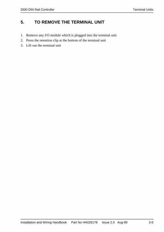
5. TO REMOVE THE TERMINAL UNIT
1. Remove any I/O module which is plugged into the terminal unit
2. Press the retention clip at the bottom of the terminal unit
3. Lift out the terminal unit

Terminal Units 2500 DIN Rail Controller
3-6 Installation and Wiring Handbook Part No HA026178 Issue 2.0 Aug-99
6. TO FIT MODULES
Each I/O module is supplied as a moulded plastic enclosure with the printed circuit boardmounted internally. A polarising key is built into the printed circuit board which locates witha corresponding slot in the correct terminal unit. A row of LED indicators show the status ofthe module and are described in further detail in subsequent chapters.
Figure 3-4: Module view
Important
1. Pull the module retaining lever forwards as shown in Figure 3-42. Line up the module in the correct terminal unit. The plugs on the module PCB should
align with the sockets on the terminal unit and module interconnection bus. The moduleretaining catch should align with the corresponding hole in the terminal unit.
Note: A polarising key is provided on the module PCB which is designed to prevent amodule from being inserted into the incorrect terminal unit.
3. When the module is correctly aligned, push the module retaining lever forwards to lockthe module into place.
Wiring of the 2500 can take place with only the terminal units fitted or after the moduleshave been fitted, as preferred. Wiring is described in following chapters.
90 mm
Module retaininglever open
Moduleretainingcatch LED status
indicators
Polarisingkey position.See table 3-1
25 mm81 mm
Module Label
Module retaining lever(closed)
114 mm

2500 DIN Rail Controller Modbus IOC Module
Installation and Wiring Handbook Part No HA026178 Issue 2.0 Aug-99 4-1
Chapter 4 Modbus I/O Controller Module
2500C/S
1. Description
The Input Output Controller (IOC) is the Central Processing Unit of the 2500 DIN railcontroller. Every base must have an IOC module. It is identified by a label on the side of themodule which gives details of model and serial number. The model number should bechecked against the Ordering Code, explained in Appendix B of this manual.
This module:• Communicates with the slave modules connected to the internal IO bus, using the Module
Interconnection printed circuit board mounted along the upper edge of the base.• Communicates to external devices, such as third party PLCs and SCADA packages, using
RJ45 connection cables and, optionally, using MODBUS comms. This is sometimesreferred to as the I/O network or ION. (See also section 5 of this chapter). Examples ofexternal devices are:-
• to connect to the operator interface unit;• to connect to a supervisory PC;• to link further slave 2500 controllers in a system;• to link further external devices such as discrete controllers, indicators, chart
recorders, drives, etc.
• Is used for system configuration, using the front panel RJ11 socket. Systemconfiguration uses Eurotherm iTools, and is covered in a separate manual, Eurotherm partno. HA026179.
This chapter explains how connections are made to the IOC to achieve the above operation.
2. Position on BaseThe IOC always occupies the slot furthest to the left hand side.
2500B/SO4
IOC 1 2 3 4
2500B/SO8
IOC 1 2 3 4 5 6 7 8
2500B/SO16
IOC 1 2 3 4 5 6 7 8 9 10 11 12 13 14 15 16
Figure 4-1: Module Positions
Note: The numbering used to define the physical location of each module, as shown in theabove sketch, is the same as that used when configuring the modules.

Modbus IOC Module 2500 DIN Rail Controller
4-2 Installation and Wiring Handbook Part No HA026178 Issue 2.0 Aug-99
3. The Modbus IOC Terminal UnitThis unit provides:• Terminal connections for the 24V DC supply to the system• RJ45 comms connectors to the Operator Interface Unit and additional plant devices• An IOC communication address switch• A PCB mounted socket for the IOC module connections
Polarisingslot position
89.8 mm
Suitable terminationsshould be made to bothends of the network
Figure 4-2: General View of the Modbus IOC Terminal Unit
+24V
2 terminals each(for daisy chaining)
RJ45 commsconnector to PC.See note 1
RJ45 comms connectorto other system devices.See note 1.
Unit addressswitch
0V
Master Operatorinterface unit
or PLC
or SupervisorySystem
Termination plug on lastdevice in the chain
Note 1:The plastic cover supplied must be fitted over theRJ45 socket when the connector is not in use
The IOC terminal blockhas two location tags,and can only be fitted inthe left most position.All other units have asingle tag
123
Fit links in postions:1 - 2 for 2 (3) wireModbus (default)2 – 3 for 4 (5) wireModbusNote: Earlier units werefitted with a single link for2(3) wire or no link for4(5) wire.
P+ P+ P- P-
Furtherinstrumentsfitted withModbuscomms.

2500 DIN Rail Controller Modbus IOC Module
Installation and Wiring Handbook Part No HA026178 Issue 2.0 Aug-99 4-3
4. To Connect the 24Vdc Power Supply
Caution: Before proceeding with any wiring of this unit, please read Chapter 14 Wiring,and Appendix A Safety and EMC Information. It is the responsibility of the installer toensure the safety and EMC compliance of any particular installation.
The power supply to the 2500 DIN rail controller is 24V DC. This may be derived from the2500P power supply unit or from an alternative 24V DC source. Connections to the systemare through the four way terminal block mounted on the IOC terminal unit. Unless otherwisestated power is supplied to all other modules in the system via the module interconnectionbus.
A suitable power supply is the 2500P described in Chapter 13 of this manual. This is a DINrail mounted unit which may be mounted adjacent to the 2500 base or remotely.
Alternatively, an existing power supply may be used provided that it has a voltage output ofbetween 18.0 1 to 28.8V DC.To calculate the system current requirements an estimate of current ratings for each module isgiven in Chapter 13, Section 1.
The IOC terminal unit contains a fuse and a reverse biased power diode. If the power iswired reverse polarity the fuse will blow and protect the complete 2500 base from damage.This fuse is not user replaceable. The unit should be returned to the factory for replacement.
Note 1:- 18V is the absolute lower limit. The use of an 18V power supply with anyappreciable voltage drop may cause unpredictable or out of specification operation.

Modbus IOC Module 2500 DIN Rail Controller
4-4 Installation and Wiring Handbook Part No HA026178 Issue 2.0 Aug-99
5. To Connect an Operator Interface UnitTwo parallel connected RJ45 communications sockets are provided. The two sockets,therefore, have the same function.One socket is used to connect the 2500 to an Operator Interface Unit, such as type T2900 ORto a conventional SCADA system. This will also allow configuration via iTools.The second socket provides a convenient way to connect additional 2500 instruments ontothe system, OR to terminate the last instrument in the chain using a MODBUS or PROFIBUSterminator, see 4.1. The terminator may also be used to terminate the 2900 Operator InterfaceUnit
The above devices are connected using RJ45 interconnection cables. These are availablefrom Eurotherm Controls in two lengths as listed in Appendix B ‘The Ordering Code’.Longer cables are available from a number of sources worldwide.
Figure 4-3: The Modbus RJ45 Connection System
RJ45 CommsLine
Terminator
Each base must beset to a uniqueaddress
RJ45 Cable Assemblies, Eurotherm Type No.2500A/CABLE/MODBUS/RJ45/RJ45/0M5or2500A/CABLE/MODBUS/RJ45/RJ45/3M0See also Appendix B ‘The Ordering Code’.
Operator Interface Unit typeT2900; 2600 or 2700ORSCADA system
Fit RJ45Comms LineTerminator if
operatorinterface isT2900, orsuitable
terminationresistor if PC.

2500 DIN Rail Controller Modbus IOC Module
Installation and Wiring Handbook Part No HA026178 Issue 2.0 Aug-99 4-5
5.1. The RJ45 Communications Line TerminatorThe communications line must be terminated using the appropriate load resistors. Tominimise on site wiring and to provide the correct resistor values, two versions of‘Terminator’ are available from Eurotherm. These are:-Eurotherm part no 2500A/TERM/MODBUS/RJ45 for Modbus communications systemsorEurotherm part no 2500A/TERM/PROFIBUS/RJ45 for Profibus communications systems
The terminator is plugged into the last RJ45 socket in the chain, as shown in Figure 4-3. Itmay also be used to terminate the T2900. If the operator interface is a PC or PLC this shouldbe terminated in accordance using the appropriate load resistors.
Figure 4-4:- The Modbus RJ45 Terminator
5.2. Connections to the RJ45 pinsRJ45 pin Colour EIA
4852 wire 4 wire
1 Orange /White
B D- TX-
2 Orange A D+ TX+3 Green / White Gnd Gnd Gnd4 Blue5 Blue / White6 Green Gnd Gnd Gnd7 Brown / White B RX-8 Brown A RX+Screen - -
NOTE: Blue and Blue/White Wires are not used.WARNING CABLE COLOURS MAY CHANGE!
Table 4-1: Connections to the Modbus RJ45 Sockets
MB120AN100Labels
Mouldingcolour
MODBUS
Black
ResistorNetwork
120Ω 5%1
100Ω 5%
120Ω 5%8
8
1

Modbus IOC Module 2500 DIN Rail Controller
4-6 Installation and Wiring Handbook Part No HA026178 Issue 2.0 Aug-99
6. The Configuration PortAn RS232 configuration port is provided on the front of the IOC, via a RJ11 socket. Whenthe IOC is powered up with a PC connected to the RJ11 configuration port, it will start in theconfiguration mode. Alternatively, the IOC is put into configuration mode by setting acommand from the configuration software. This is further described in the ‘iTools’ manual.
Note:- Exiting configuration mode must be done using iTools or through communications.
The IOC will not control the process if:1. It is in configuration mode or standby mode2. A network watchdog time-out occurs (if configured)3. It is removed from the systemUnder these conditions all modules will enter a ‘safe’ state. Generally this defaults as digitaloutput modules will go to an OFF state, and analogue output modules will go to a minimumoutput state (generally 0V or 4mA).
Connections to this socket are given below:
Pin connectionsRJ11 into IOC
Pin connections on 9way D-type into PC
Pin connections on 25way D-type into PC
6 no connection -5 RX 3 TX 2 TX4 TX 2 RX 3 RX3 0V 5 0V 7 0V2 no connection1 24V (in)Screen Screen 1 Screen
Table 4-2: Connections to the RJ11 Sockets
Figure 4-5: View of the Configuration RJ11 Plug and Socket
RJ11-6 way
To IOC
Connectors at theback
16
6
View into end ofsocket
1
2500Modbus

2500 DIN Rail Controller Modbus IOC Module
Installation and Wiring Handbook Part No HA026178 Issue 2.0 Aug-99 4-7
6.1. Configuration ConnectionsIt is recommended that the connections between the PC and the IOC use a standard RJ11 to 9pin cable assembly available from Eurotherm as shown in ‘The Ordering Code’, Appendix BThis cable plugs directly into the IOC and the PC as shown below.Using the Eurotherm cable with the appropriate power supply allows the IOC to beprogrammed remote from the system providing desk top configuration.
Figure 4-6: Connection Between IOC and PC using RJ11 Cable Assembly
Note:- The standard RJ45 socket can also be used to configure the IOC using RS485communications, but the address is that set by the address switch. If the IOC is configuredvia the RJ11 system the unit will appear at BOTH address 255 AND the switch address.Address switch set to zero is a special case in which the controller is ‘soft’ configured, i.e.configured and stored in non-volatile memory.
Modbus
PC
9 way connector
RJ11 Cable Assembly, Eurotherm Ordering Code2500A/CABLE/CONFIG/RJ11/9PINDFSee also Ordering Code, Appendix B.
IOC
PC used forconfiguration
24V Powersupply
The plastic coversupplied must be fittedover the RJ11 socketwhen the connector isnot in use
Optional Power Supplyand cable to enable IOCto be configuredremotely
X
C
S
2500
+
Voltagepolarity ofsocket
-

Modbus IOC Module 2500 DIN Rail Controller
4-8 Installation and Wiring Handbook Part No HA026178 Issue 2.0 Aug-99
7. To Set The Address SwitchThe unit address and parity is selected by the dual in line (DIL) switch mounted on theterminal unit.Sixty-three Modbus addresses can be set in binary using positions 1 to 6. Parity has threepossible states - none/even/odd - thus using positions 7 & 8. The diagram below shows thesetting of the switch:If the address switch is set to all OFF, then the IOC expects to have its address set by theconfiguration tools. This is further described in the iTools manual, Eurotherm part noHA026179. For addresses between 65 and 255 the address switch must be set all OFF andthe address set in iTools.
Figure 4-7: The Modbus Address Switch Set To -Unit Address 05, Parity off
8. Baud rateBaud rate is set using the configuration software, see iTools Manual Eurotherm part no.HA026179. For information, however, the table below shows the rates that are supported.
Baud rate Software versionV1.X V2.X
1200240048009600 9 9
19,200 9 9
38,400
Table 4-3: Baud Rate
ON
OFF
12345678
12481632OP
EP
Switch position
Modbus Address
P Parity on
P Parity off
O Odd
E Even

2500 DIN Rail Controller Modbus IOC Module
Installation and Wiring Handbook Part No HA026178 Issue 2.0 Aug-99 4-9
9. Status IndicationFive LED indicators show the status of the module as follows:
Note 1:- Indication of standby condition using this LED is not implemented in softwareversion 1.01
Figure 4-8: IOC Status Indication
LED Colour ON ALL OFF
S
C
Green
Yellow
Yellow
Normal operation
Standby (See Note 1)
Configuration
Self test failed onpower up
LED Colour ON OFFX Red IOC reset or
Module missing,faulty or wrong type
or non-volatilememory failure
Normal operation
FlashingX Red Power on self test
failed
LED Colour ON OFFYellow IO network or
configuration portcommunicating
Modbus
X
C
S
2500

Modbus IOC Module 2500 DIN Rail Controller
4-10 Installation and Wiring Handbook Part No HA026178 Issue 2.0 Aug-99
10. InitialisationThe IOC goes through an initialisation sequence when power is applied, and will start in oneof three modes.1. Operating Mode. This is the usual start up mode. The I/O does not have to be correctly
configured for the IOC to begin running.2. Standby mode. This is intended to be used for strategy engine controlled start-up. A
config mode parameter will provide the option to ‘Start-up in Standby’.3. Configuration Mode. When the IOC is powered up with a PC connected to the RJ11
config port, it will start in the config mode. To guarantee that this happens the PC shouldnot be communicating at the time of powering up the IOC.
11. Power on self testWhen the unit is switched on or when the module is in reset mode, a self test sequence takesplace. During this self test period, the LEDs follow a sequence lasting approximately 5-10seconds. The sequence is shown in Figure 4-9 and shows the state of the LEDs for both passand fail conditions.

2500 DIN Rail Controller Modbus IOC Module
Installation and Wiring Handbook Part No HA026178 Issue 2.0 Aug-99 4-11
LEDTest
FlashROM
RAMTest
NvolTest
Watch-dog Test NvolCheck-
sumTest
Initial-isation
FullOpera-
tion(2)
Note 1
Note 2
Figure 4-9: Power On Self Test - LED Status Indication
X
C
S
Power On
LED Test
ROMTest Pass
RAMTest Pass
NvolTest Pass
WatchdogTest Pass
Nvol ChecksumsTest Pass
Rom TestFail
RAM Test Fail
Nvol Test Fail
Nvol Checksum Failure
Watchdog Test Fail
‘Flashing'
LED On
LED Off
(2)
Top LED is ON if the 2500 is in operation level
Centre LED ON if the 2500 is in standby
Lower LED ON if the 2500 is in configuration modeC
S

Modbus IOC Module 2500 DIN Rail Controller
4-12 Installation and Wiring Handbook Part No HA026178 Issue 2.0 Aug-99
12. Modes of Operation12.1. Standby ModeIndication that the IOC is in standby mode is via a yellow LED on the front of the module,(See ‘Status Indication’ page 4-9). The behaviour in standby mode is as follows :1. The Inputs continue to be scanned and linearised.2. Outputs go to their ‘off’ values, e.g. Digitals - Off, Analogues - to their minimum
settings or low limits (not necessarily zero output).3. Deviation Alarms are disabled. i.e. Full scale alarms will continue to function.4. The Alarm Blocking feature is re-initialised on leaving standby mode for Deviation
alarms only. i.e. Full scale alarms will not be blocked.5. The outputs from the deviation Alarms are disabled.6. The status LED’s on the front of the IOS will indicate that the IOS is not operating the
plant in standby mode7. Standby mode will be indicated over comms by setting the Instrument Mode parameter to
1 (one) i.e.Operating Mode 0Standby Mode 1Configuration Mode 2
8. The transfer from standby to operating mode does not require an instrument reset.9. Control outputs behave as follows:
• The PID output set to 0.0%.• The PID will bumpless transfer on changing to operating mode• The analogue output ranges will still operate. i.e. A 4-20mA output will be
clipped to 4 mA.
12.2. Configuration ModeThe behaviour in Configuration mode is the same as in Standby mode with the additionalability to re-configure the 2500.Configuration of the IOC uses the Eurotherm configuration software, ‘iTools’. A descriptionof this configuration tool is given in the iTools handbook, part number HA026179.Configuration mode can be entered as follows:When the IOC detects the presence of a PC connected to the RJ11 socket during power up.By setting the ‘Instrument Mode’ to 2 over the communications link.Configuration mode is indicated by a yellow LED on the front of the module (See ‘StatusIndication’ page 4-9).Notes:1. If an I/O slot is not populated or the IOC is stand alone (i.e. not connected to an I/O base
at all) then a slot may be configured for any function.2. It is possible to exit configuration mode without the configured slot functions matching
the actual modules.3. Where a slot function has been previously been defined in CONFIG mode, modules may
be removed and replaced outside CONFIG mode.If the IOC has been put into configuration mode over the communications link, it will stay inconfiguration unless it is explicitly set into operating mode.

2500 DIN Rail Controller Profibus IOC Module
Installation and Wiring Handbook Part No HA026178 Issue 2.0 Aug-99 5-1
Chapter 5 PROFIBUS I/O Controller Module
2500C/S
1. DescriptionThe Input Output Controller (IOC) is the Central Processing Unit of the 2500 DIN railcontroller. Every base must have an IOC module. It is identified by a label on the side of themodule, which gives details of model and serial number. The model number should bechecked against the Ordering Code, explained in Appendix B of this manual.The module can be fitted into one of two terminal units. These are the ‘Profibus IOCTerminal Unit’, described in section 3, and the ‘RJ45 IOC Terminal Unit’, described insection 4.
This module:• Communicates with the slave modules connected to the internal IO bus, using the Module
Interconnection printed circuit board mounted along the upper edge of the base.• Communicates to external devices, such as third party PLCs and SCADA packages, using
a 9 PIN D connector (or RJ45 connectors) and PROFIBUS DP communications. This issometimes referred to as the I/O network or ION. Examples of external devices are:-
• to connect to a supervisory PC or PLC;• to link further slave 2500 controllers in a system;• to add further external slave devices such as discrete controllers, indicators,
chart recorders, drives, etc.• Is used for system configuration, using the front panel RJ11 socket. System
configuration uses Eurotherm iTools, and is covered in a separate manual, Eurotherm partno. HA026179.
This chapter explains how connections are made to the IOC to achieve the above operation.
2. Position on BaseThe IOC is always in the slot furthest to the left.
2500B/SO4
IOC 1 2 3 4
2500B/SO8
IOC 1 2 3 4 5 6 7 8
2500B/SO16
IOC 1 2 3 4 5 6 7 8 9 10 11 12 13 14 15 16
Figure 5-1: Module Positions
Note: The numbering used to define the physical location of each module, as shown in theabove sketch, is the same as that used when configuring the modules.

Profibus IOC Module 2500 DIN Rail Controller
5-2 Installation and Wiring Handbook Part No HA026178 Issue 2.0 Aug-99
3. The Profibus IOC Terminal UnitThe Profibus IOC terminal unit has a single 9 Pin D socket commonly used with PROFIBUSDP. The unit provides:• Terminal connections for the 24V DC supply to the system• A 9 Pin D comms connector to the PROFIBUS master and additional slave devices• An IOC communication address switch• A PCB mounted socket for the IOC module connections
Furtherinstrumentsfitted withProfibuscomms.
Figure 5-2: General View of the 9 pin D Profibus IOC Terminal Unit
Polarisingslot position
89.8 mm
+24V2 terminals each(for daisy chaining)
Unit addressswitch
0V
Master Operatorinterface unit
or PLC
or SupervisorySystem
Termination switch onlast device in the chainShould be ON
TerminationOn PC
9 pin D commsconnector to PC andslave devices
Profibus 9 pin Dcable plugs can take2 cables and includea terminationON/OFF switch.
P+ P+ P-P-

2500 DIN Rail Controller Profibus IOC Module
Installation and Wiring Handbook Part No HA026178 Issue 2.0 Aug-99 5-3
4. To Connect an IOC in a Profibus DP network.Each slave must have a unique address, set on the IOC terminal unit. The communicationscable should be run in a single link running from device to device, and not in a ‘star’arrangement. The first and last device in the link must have a termination load.
4.1. 9 Pin ConnectorsFor 9 pin D connectors standard Profibus cables should be used. These cables have specialheaders on the 9 pin D male connector which allow one or two cables to be connected intothem and have a small termination load built in with an ON/OFF switch, which is set to ONat the two ends of the link.The Profibus standard states that two types of cable, ‘Line A’ and ‘Line B’, may be used.The termination details for these two types of cable are shown in Figure 5-3.
Figure 5-3: Profibus Terminations on 9 Pin Connectors
Profibus 9 Pin D Connections
Pin No. RS 485 Ref Signal Name Meaning1 Shield * Shield, Protective
ground resp.2 Not used in 25003 B/B RxD/TxD-P Receive/Transmit –
Data - P4 Not used in 25005 C/C DGND Data ground6 VP 1 Voltage – Plus7 Not used in 25008 A/A RxD/TxD-N Receive/Transmit –
Data – N9 Not used in 2500* Signals are optionalFor further information on recommended wiring, see EMC Installation Guide Part No.HA025464.
Table 5-1: Profibus 9 Pin Connections
390Ω
390Ω
220Ω ProfibusLine A
6
3
8
5
390Ω
390Ω
150ΩProfibusLine B
6
3
8
5

Profibus IOC Module 2500 DIN Rail Controller
5-4 Installation and Wiring Handbook Part No HA026178 Issue 2.0 Aug-99
5. The RJ45 IOC Terminal Unit.It is also possible to use the 2500 with the RJ45 connector system but it is not fully compliantwith the Profibus standard. This system is intended for use with other products in the 2500range.
Figure 5-4: General View of the Profibus RJ45 IOC Terminal Unit
* Suitable termination on the last device in the chain.On earlier units the use of the termination plug isrecommended as shown.On later units fit either the termination unit or both linksin position 1 & 2, see above.
Polarisingslot position
89.8 mm
Note 1:The plastic cover suppliedmust be fitted over the RJ45socket when the connectoris not in use
+24V
2 terminals each(for daisy chaining)
RJ45 commsconnector to PC.See note 1
RJ45 comms connectorto other system devices.See note 1.
Unit addressswitch
0V
Master Operatorinterface unit
or PLC
or SupervisorySystem
Suitableterminationsshould bemade to bothends of thenetwork
123
P+ P+ P-P-
* Fit both links:• 1 - 2 to terminate
the Profibus network• 2 - 3 (or none) for
no termination.
Note: Earlier units werefitted with a single link.On these units this linkhas no function and thesystem should beterminated using thetermination plug.
Furtherinstrumentsfitted withProfibuscomms.

2500 DIN Rail Controller Profibus IOC Module
Installation and Wiring Handbook Part No HA026178 Issue 2.0 Aug-99 5-5
6. To Connect an IOC in a Profibus DP network.Each slave must have a unique address, set on the IOC terminal unit. The communicationscable should be run in a single link running from device to device, and not in a ‘star’arrangement. The first and last device in the link must have a termination load.
6.1. RJ45 Connector SystemIf the RJ45 connector system is used a standard cable is available. Similarly, to providesuitable terminations for the system a standard part is available to terminate the system. Thepart numbers for these is given in Appendix B, ‘The Ordering Code’.
The terminator is plugged into the last RJ45 socket in the chain, as shown in Figure 5-4. Ifthe operator interface is a T2900 a second terminator should be plugged into this. If theoperator unit is a PC or PLC this should be terminated using the appropriate load resistors.
Figure 5-5:- The Profibus RJ45 Terminator
RJ45 Pin Connections
RJ45pin
Definition Colour Profibus
1 Line most NEGATIVE when UARTis low (0v/space/start-bit)
Orange / White D-
2 Line most POSITIVE when UARTis low (0v/space/start-bit)
Orange D+
3 Ground Green / White Gnd4 - Blue5 - Blue / White6 Ground Green +5V7 - Brown / White8 - BrownScreen Chassis -
Warning: cable colours may change!
Table 5-2: Connections to the Profibus RJ45 Sockets
PROFI
Labels
Mouldingcolour
PROFIBUS
Grey
130Ω 1%
180Ω 1%
180Ω 1%
1
8
8
1

Profibus IOC Module 2500 DIN Rail Controller
5-6 Installation and Wiring Handbook Part No HA026178 Issue 2.0 Aug-99
7. To Connect the 24Vdc Power Supply
Caution: Before proceeding with any wiring of this unit, please read Chapter 11 Wiring,and Appendix A Safety and EMC Information. It is the responsibility of the installer toensure the safety and EMC compliance of any particular installation.
The power supply to the 2500 DIN rail controller is 24V DC. This may be derived from the2500P power supply unit or from an alternative 24V DC source. Connections to the systemare through the four way terminal block mounted on the IOC terminal unit. Unless otherwisestated power is supplied to all other modules in the system via the module interconnectionbus.
A suitable power supply is the 2500P described in Chapter 13 of this manual. This is a DINrail mounted unit which may be mounted adjacent to the 2500 base or remotely.
Alternatively, an existing power supply may be used provided that it has a voltage output ofbetween 18.01 to 28.8V DC.To calculate the system current requirements an estimate of current ratings for each module isgiven in Chapter 13, Section 1.
The IOC terminal unit contains a fuse and a reverse biased power diode. If the power iswired reverse polarity the fuse will blow and protect the complete 2500 base from damage.This fuse is not user replaceable. The unit should be returned to the factory for replacement.
Note 1:- 18V is the absolute lower limit. The use of an 18V power supply with anyappreciable voltage drop may cause unpredictable or out of specification operation.

2500 DIN Rail Controller Profibus IOC Module
Installation and Wiring Handbook Part No HA026178 Issue 2.0 Aug-99 5-7
8. The Configuration PortAn RS232 configuration port is provided on the front of the IOC, via a RJ11 socket. Whenthe IOC is powered up with a PC connected to the RJ11 configuration port, it will start in theconfiguration mode. Alternatively, the IOC is put into configuration mode by setting acommand from the configuration software. This is further described in the ‘iTools’ manual.
Note:- Exiting configuration mode must be done using iTools or through communications.
The IOC will not control the process if:1. It is in configuration mode or standby mode2. A network watchdog time-out occurs (if configured)3. It is removed from the systemUnder these conditions all modules will enter a ‘safe’ state. Generally this defaults as digitaloutput modules will go to an OFF state, and analogue output modules will go to a minimumoutput state (generally 0V or 4mA).
Connections to this socket are given below:
Pin connectionsRJ11 into IOC
Pin connections on 9way D-type into PC
Pin connections on 25way D-type into PC
6 no connection -5 RX 3 TX 2 TX4 TX 2 RX 3 RX3 0V 5 0V 7 0V2 no connection1 24V (in)Screen Screen 1 Screen
Table 5-3: Connections to the RJ11 Sockets
Figure 5-6: View of the RJ11 Plug and Socket
RJ11-6 way
To IOC
Connectors at theback
16
6
View into end ofsocket
1
2500Profibus

Profibus IOC Module 2500 DIN Rail Controller
5-8 Installation and Wiring Handbook Part No HA026178 Issue 2.0 Aug-99
8.1. Configuration ConnectionsIt is recommended that the connections between the PC and the IOC use a standard RJ11 to 9pin cable assembly available from Eurotherm as shown in ‘The Ordering Code’, Appendix BThis cable plugs directly into the IOC and the PC as shown below.Using the Eurotherm cable with the appropriate power supply allows the IOC to beprogrammed remotely from the system, permitting desk top configuration.
Figure 5-7: Connection Between IOC and PC using RJ11 Cable Assembly
Note:- The Profibus communications interface does not operate whilst the configuration portis connected.
Profibus
PC
9 way connector
RJ11 Cable Assembly, Eurotherm Ordering Code2500A/CABLE/CONFIG/RJ11/9PINDFSee also Ordering Code, Appendix B.
IOC
PC used forconfiguration
24V Powersupply
The plastic coversupplied must be fittedover the RJ11 socketwhen the connector isnot in use
Optional Power Supplyand cable to enable IOCto be configuredremotely
X
C
S
2500
+
Voltagepolarity ofsocket
-

2500 DIN Rail Controller Profibus IOC Module
Installation and Wiring Handbook Part No HA026178 Issue 2.0 Aug-99 5-9
9. To Set The Address SwitchThe unit address and parity is selected by the dual in line (DIL) switch mounted on theterminal unit.The switch gives 127 addresses from 1 to 127. Address 0 is invalid.
Figure 5-8: The Profibus Address switch
10. Baud rateBaud rate is set by the Profibus Master which is able to detect the fastest Baud at which allslaves can operate. The Profibus IOC is capable of operating at 12Mbaud.
ON
OFF
1234567
1248163264Note:-Switch 8 is not normallyused.If, however, it is set to ONthe unit address is settableover communications.
Profibus Address
Switch position

Profibus IOC Module 2500 DIN Rail Controller
5-10 Installation and Wiring Handbook Part No HA026178 Issue 2.0 Aug-99
11. Status IndicationFive LED indicators show the status of the module as follows:
Figure 5-9: IOC Status Indication
LED Colour ON ALL OFF
S
C
Green
Yellow
Yellow
Normal operation
Standby (See Note1)
Configuration
Self test failed onpower up
LED Colour ON OFFX Red IOC reset or
Module missing,faulty or wrong type
or non-volatilememory failure.
Normal operation
FlashingX Red Power on self test
failed
LED Colour ON OFFYellow IO network or
configuration portcommunicating
Profibus
X
C
S
2500

2500 DIN Rail Controller Profibus IOC Module
Installation and Wiring Handbook Part No HA026178 Issue 2.0 Aug-99 5-11
12. InitialisationThe IOC goes through an initialisation sequence when power is applied, and will start in oneof three modes.1. Operating Mode. This is the usual start up mode. The I/O does not have to be correctly
configured for the IOC to begin running.2. Standby mode. This is intended to be used for strategy engine controlled start-up. A
config mode parameter will provide the option to ‘Start-up in Standby’.3. Configuration Mode. When the IOC is powered up with a PC connected to the RJ11
config port, it will start in the config mode. To guarantee that this happens the PC shouldnot be communicating at the time of powering up the IOC.
13. Power on self testWhen the unit is switched on or when the module is in reset mode, a self test sequence takesplace. During this self test period, the LEDs follow a sequence lasting approximately 5 to 10seconds. The sequence is shown in Figure 4-9 (Chapter 4) and shows the state of the LEDsfor both pass and fail conditions.
14. Modes of Operation
14.1. Standby ModeIndication that the IOC is in standby mode is via a yellow LED on the front of the module,(See ‘Status Indication’ page 5-10). The behaviour in Configuration mode is the same as inStandby mode with the addition of the ability to re-configure the 2500.The behaviour of the instrument in standby mode is as follows:-1. The Inputs continue to be scanned and linearised.2. Outputs go to their ‘off’ values, e.g. Digitals - Off, Analogues - to their minimum
settings or low limits (not necessarily zero output).3. Deviation Alarms are disabled. i.e. Full scale alarms will continue to function.4. The Alarm Blocking feature is re-initialised on leaving standby mode for Deviation
alarms only. i.e. Full scale alarms will not be blocked.5. The outputs from the deviation Alarms are disabled6. The status LED’s on the front of the IOS will indicate that the IOS is not controlling the
plant in standby mode7. Standby mode will be indicated over comms by setting the Instrument Mode parameter to
1 (one) i.e.Operating Mode 0Standby Mode 1 Configuration Mode 2
8. The transfer from standby to operating mode does not require an instrument reset.9. Control outputs behave as follows:
• The PID output set to 0.0%.• The PID will bumpless transfer on changing to operating mode

Profibus IOC Module 2500 DIN Rail Controller
5-12 Installation and Wiring Handbook Part No HA026178 Issue 2.0 Aug-99
• The analogue output ranges will still operate. i.e. A 4-20mA output will beclipped to 4 mA.
14.2. Configuration ModeThe behaviour in Configuration mode is the same as in Standby mode with the addition of theability to re-configure the 2500.Configuration of the IOC uses the Eurotherm configuration software, ‘iTools’. A descriptionof this configuration tool is given in the iTools handbook, part number HA026179.Configuration mode can be entered as follows:When the IOC detects the presence of a PC connected to the RJ11 socket on the front of themodule at power up.By setting the ‘Instrument Mode’ to 2 over the communications link.Configuration mode is indicated by a yellow LED on the front of the module (See ‘StatusIndication’ page 5-10).Notes:1. If an I/O slot is not populated or the IOC is stand alone (i.e. not connected to an I/O base
at all) then a slot may be configured for any function.2. It is possible to exit configuration mode without the configured slot functions matching
the actual modules.3. Where a slot function has been previously been defined in CONFIG mode, modules may
be removed and replaced outside CONFIG mode.If the IOC has been put into configuration mode over the communications link, it will stay inconfiguration unless it is explicitly set into operating mode.

2500 DIN Rail Controller Two Channel Analogue Input Module
Installation and Wiring Handbook Part No HA026178 Issue 2.0 Aug-99 6-1
Chapter 6 Two Channel Analogue Input Module2500M/AI2
1. DESCRIPTION
The analogue input module is used to measure analogue signals from a range of plant sensors.These include :• Thermocouples• Platinum Resistance Thermometers (2 & 3 wire)• Voltage +10V and +100mV• High Impedance (Zirconia)• Current +20mA.
The analogue input module consists of two input channels, isolated from each other andisolated from the system electronics, (see specification Appendix A for further details).
For thermocouple inputs Cold Junction Temperature is measured by a RTD sensor fitted tothe terminal unit.
2. MODULE IDENTIFICATION
The module may be identified by means of labels on the side and front of the case. The sidelabel includes details of the product code and serial number. The product code should bechecked against the coding details given in Appendix B.
3. CONFIGURATION
The configuration of the Analogue Input Module is stored in the IOC. It can be configured ormodified using the PC based configuration station connected to the configuration port in theIOC. This is covered by the ‘iTools Handbook’ part number HA026179.
Typical parameters which can be configured or changed include:• Input Type• Range• Input Filter Time Constant• Sensor Break Action• User Calibration. This allows you to offset the ‘permanent’ factory calibration to :a) Calibrate the controller to your reference standardsb) Match the calibration of the controller to that of a particular transducer or sensorc) Calibrate the controller to suit the characteristics of a particular installation
4. LOCATION
The module may be located, with its matching terminal unit, in any position on the base,other than the left hand position reserved for the IOC.
Two Channel Analogue Input Module 2500 DIN Rail Controller
6-2 Installation and Wiring Handbook Part No HA026178 Issue 2.0 Aug-99
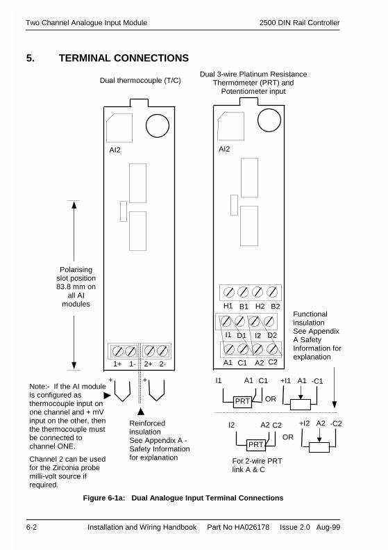
5. TERMINAL CONNECTIONS
Figure 6-1a: Dual Analogue Input Terminal Connections
Note:- If the AI moduleis configured asthermocouple input onone channel and + mVinput on the other, thenthe thermocouple mustbe connected tochannel ONE.
Channel 2 can be usedfor the Zirconia probemilli-volt source ifrequired.
Dual thermocouple (T/C)
1+ 1- 2+ 2-
AI2
ReinforcedinsulationSee Appendix A -Safety Informationfor explanation
FunctionalinsulationSee AppendixA SafetyInformation forexplanation
Polarisingslot position83.8 mm on
all AImodules
+ +
Dual 3-wire Platinum ResistanceThermometer (PRT) and
Potentiometer input
A1 C1 A2 C2
I1
B1H1 B2
I2
H2
PRT
C1I1 A1
PRT
I2 C2A2
AI2
D1 D2
For 2-wire PRTlink A & C
+I1 -C1A1
OR
+I2 -C2
OR
A2

2500 DIN Rail Controller Two Channel Analogue Input Module
Installation and Wiring Handbook Part No HA026178 Issue 2.0 Aug-99 6-3
Figure 6-1b: Dual Analogue Input Terminal Connections
mA
+A2 -C2
mA
+A1 -C1
Zr
+A2 -C2
Functional insulation SeeAppendix A - SafetyInformation for explanation
Dual Volts (V) ormilli-volts (mV)
Dual milli-amps(mA) Shunt Option
High impedanceinput(Zirconia Probe)
A1 C1 A2 C2
I1
B1H1 B2
I2
H2
AI2
D1 D2
A1 C1 A2 C2
I1
B1H1 B2
I2
H2
AI2
D1 D2
A1 C1 A2 C2
I1
B1H1 B2
I2
H2
AI2
D1 D2
5Ω5Ω
V
+H1 -C1
mV
+A1 -C1
OR
V
+H2 -C2
mV
+A2 -C2
ORNotes:-The shunt option has 5Ω resistors mounted on the rear of the PCB.The mV option may also be used for mA inputs if fitted with suitable 5Ω external burdenresistors. It permits a 0-20mA input to provide a full scale range of 0-100mV.
SHUNT

Two Channel Analogue Input Module 2500 DIN Rail Controller
6-4 Installation and Wiring Handbook Part No HA026178 Issue 2.0 Aug-99
6. ANALOGUE INPUT EQUIVALENT CIRCUITS
The equivalent circuits below show details of analogue inputs, in particular sensor breakcircuits.
Thermocouple Input
Figure 6-2: Thermocouple Input
3-Wire PRT Input
Figure 6-3: 3-Wire PRT Input
T/C BreakAction
Internal view
20MΩ
VRef
Gnd
Up
Down
None
High impedanceinput amplifier
1+
1-
CJCThermocouple
SensorBreakAction
Internal view
8K2Ω
VRef
High impedanceinput amplifier
A1
C1
I1
PRT
Gnd
Down
Up
None20MΩ

2500 DIN Rail Controller Two Channel Analogue Input Module
Installation and Wiring Handbook Part No HA026178 Issue 2.0 Aug-99 6-5
Milli-Volt Input
Figure 6-4: mV InputVolts Input
Figure 6-5: Volts Input
Milli-Amp Input
Figure 6-6: mA Input
270KΩ
C1 orC2
H1 orH2
33KΩHigh impedanceinput amplifier
VoltageSource
Internal View
270KΩ
High impedanceinput amplifier
A1 orA2
C1 orC2
H1 orH2
Internal View
m-VoltSource
Gnd
Up
Down
None20MΩ Sensor
BreakAction
C1 orC2
A1 orA2
CurrentSource
Internal View
5ΩHigh impedanceinput amplifier

Two Channel Analogue Input Module 2500 DIN Rail Controller
6-6 Installation and Wiring Handbook Part No HA026178 Issue 2.0 Aug-99
STATUS INDICATION
Three LED indicators show the status of the module as follows:
Figure 6-7: Dual Analogue Input Status Indication
LED Colour ON OFF
Green Normaloperation
Fault Condition
No power
or
No comms
or
Wrong module type
LED Colour ON OFF
1Ch1
2Ch2
Red
Red
Ch1 sensor break orInitialising
Ch 2 sensor break or
Initialising
Normal operationch1
Normal operation
ch2
Flashing Blinking ON
1Ch1
2Ch2
Red
Red
Ch1 CJC fail or
Ch1 bad cal data
Ch2 CJC fail or
Ch2 bad cal data
Calibrating ch1
Calibrating ch2
AI2
2
1
Definitions Approx. ON time Approx. OFF time Approx. flash rate
Flashing 0.5 sec 0.5 sec 1 sec
Blinking ON 0.2 sec 2 sec 2 sec

Installation and Wiring Handbook Three Channel Analogue Input Module
2500 DIN Rail Controller 7-1
Chapter 7 Three Channel Analogue Input Module2500M/AI3
1. DESCRIPTION
The AI3 offers 3 isolated current input channels. The module hardware provides fixed rangecapable of ±20mA at high resolution; configuration provides applications ranging. Eachchannel has an internal burden resistor requiring less than 1 volt and in most applications theinputs will be used for 4-20mA signals.Each isolated channel will have its own 24V supply for external transmitter excitation.
2. MODULE IDENTIFICATION
The module may be identified by means of labels on the side and front of the case. The sidelabel includes details of the product code and serial number. The product code should bechecked against the coding details given in Appendix B.
3. CONFIGURATION
The configuration of the Analogue Input Module is stored in the IOC. It can be configured ormodified using the PC based configuration station connected to the configuration port in theIOC. This is covered by the ‘iTools Handbook’ part number HA026179.
Typical parameters which can be configured or changed include:• Input Range• Input Filter Time Constant• User Calibration. This allows you to offset the ‘permanent’ factory calibration to :a) Calibrate the controller to your reference standardsb) Match the calibration of the controller to that of a particular transducer or sensorc) Calibrate the controller to suit the characteristics of a particular installation
4. LOCATION
The module may be located, with its matching terminal unit, in any position on the base,other than the left-hand position reserved for the IOC.
5. BRIEF SPECIFICATION
Parameter ValuesInput Range -20 to +20mAMax input resistance 100 Ω (or 250Ω if link
broken on terminal unit)Channel sample period 110mSTransducer Power Supply 21.0 to 25.0 VTransducer power supply Output Impedance 10ΩTransducer power supply Current Trip >25mA and < 55mATransducer power supply Current Trip Reset Auto – every 14 sec

Three Channel Analogue Input Module Installation and Wiring Handbook
7-2 2500 DIN Rail Controller
6. TERMINAL CONNECTIONS
Connections are shown below for inputs where the transmitter requires excitation, and forthose generating their own current. Each channel can be wired as required.
Figure 7-1: Three Channel Analogue Input Terminal Connections
I1 I2 I3
C1
P2P1
C3
P3
I1
C1
AI3AI3
FunctionalinsulationSee Appendix ASafetyInformation forexplanation
C2
Polarisingslot position77.8 mm on
all AI3modules
I2
C2
I3
C3
4-20mA self powered inputs
I1 I2 I3
C1
P2P1
C3
P3
C2
P1
C1
P2
C2
P3
C3
4-20mA module powered inputs
mA mA mA mA mA mANote:-C1 to C3 is+ve
Installation and Wiring Handbook Three Channel Analogue Input Module
2500 DIN Rail Controller 7-3
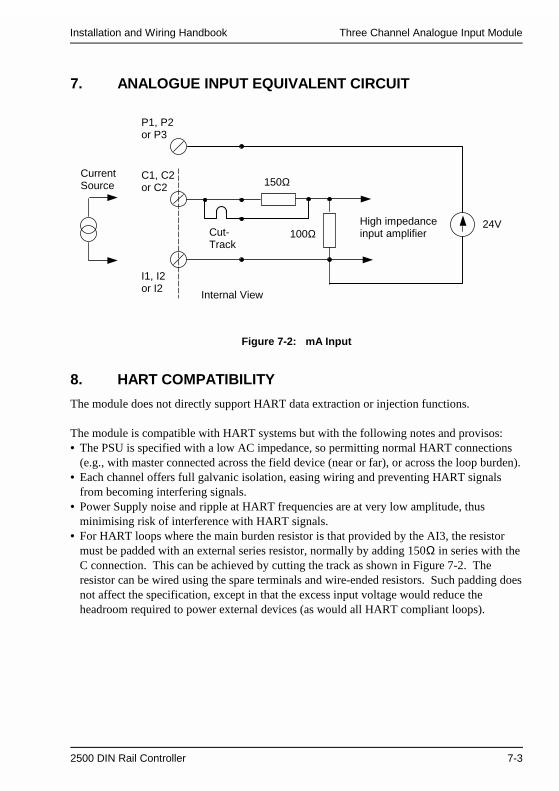
7. ANALOGUE INPUT EQUIVALENT CIRCUIT
Figure 7-2: mA Input
8. HART COMPATIBILITY
The module does not directly support HART data extraction or injection functions.
The module is compatible with HART systems but with the following notes and provisos:• The PSU is specified with a low AC impedance, so permitting normal HART connections
(e.g., with master connected across the field device (near or far), or across the loop burden).• Each channel offers full galvanic isolation, easing wiring and preventing HART signals
from becoming interfering signals.• Power Supply noise and ripple at HART frequencies are at very low amplitude, thus
minimising risk of interference with HART signals.• For HART loops where the main burden resistor is that provided by the AI3, the resistor
must be padded with an external series resistor, normally by adding 150Ω in series with theC connection. This can be achieved by cutting the track as shown in Figure 7-2. Theresistor can be wired using the spare terminals and wire-ended resistors. Such padding doesnot affect the specification, except in that the excess input voltage would reduce theheadroom required to power external devices (as would all HART compliant loops).
150ΩC1, C2or C2
P1, P2or P3
100ΩHigh impedanceinput amplifier
CurrentSource
Internal View
I1, I2or I2
24VCut-Track

Three Channel Analogue Input Module Installation and Wiring Handbook
7-4 2500 DIN Rail Controller
9. STATUS INDICATION
The status of the module is shown by three LED indicators as follows:
* IOC firmware prior to software issue 2.21 will not recognise an AI3 module.
Figure 7-3: Three Channel Analogue Input Status Indication
LED Colour ON OFF
Green Normaloperation
Fault Condition
No power
or
No comms
or
Unrecognised module type *
or
Wrong module type
LED Colour ON OFF
1
2
3
Red
Red
Red
Channel 1 loop break orInitialising
Channel 2 loop break orInitialising
Channel 3 loop break orInitialising
Normal
Normal
Normal
Flashing BlinkingON
1
2
3
Red
Red
Red
Channel 1 bad calibration
Channel 2 bad calibration
Channel 3 bad calibration
Calibrating
Calibrating
Calibrating
Definitions Approx. ON time Approx. OFF time Approx. flash rate
Flashing 0.5 sec 0.5 sec 1 sec
Blinking ON 0.2 sec 2 sec 2 sec
AI3
2
1
3
2500 DIN Rail Controller Two Channel Analogue Output Module
Installation and Wiring Handbook Part No HA026178 Issue 2.0 Aug-99 8-1
Chapter 8 Two Channel Analogue Output Module2500M/AO2
1. DESCRIPTION
The analogue output module provides two analogue output channels, isolated from each otherand isolated from the system electronics. Each output may be configured as either voltage orcurrent:
2. MODULE IDENTIFICATION
The module may be identified by means of labels on the side and front of the case. The sidelabel includes details of the product code and serial number. the product code should bechecked against the coding details given in Appendix B.
3. CONFIGURATION
The configuration of the Analogue Output Module is stored in the IOC. It can be configuredor modified using the PC based configuration station connected to the configuration port inthe IOC. Configuration is covered by the ‘iTools Handbook’ part number HA026179.
Typical operating outputs which can be configured include:
• 10V 5mA max• 20mA 12V dc max• 5V 10mA max• Output range limit 30V max, 40mA max.
4. LOCATION
The module may be located, with its matching terminal unit, in any position on the base,other than the left hand position reserved for the IOC.

Two Channel Analogue Output Module 2500 DIN Rail Controller
8-2 Installation and Wiring Handbook Part No HA026178 Issue 2.0 Aug-99
5. TERMINAL CONNECTIONS
Figure 8-1: Two Channel Analogue Output Terminal Connections
Current ModeNote: The input impedance (or loopimpedance) ‘Ri’ of the device connected to theanalogue output module must be < 600Ω
Functional insulationSee Appendix A - Safety Information for explanation
2+ 2-
mA
1+ 1-
mA
Ri
1+ 1- 2+ 2-
AO2
Polarisingslot position
85.8 mm
Ri
2+ 2-1+ 1-
Rv Rv
Voltage ModeNote: The input impedance ‘Rv’ of the deviceconnected to the analogue output modulemust be > 2KΩ for 10V range.

2500 DIN Rail Controller Two Channel Analogue Output Module
Installation and Wiring Handbook Part No HA026178 Issue 2.0 Aug-99 8-3
6. ANALOGUE OUTPUT EQUIVALENT CIRCUITS
Figure 8-2: Voltage Output
Figure 8-3: Current Output
1+ or2+
1- or2-
>2KΩ (10V output)>1KΩ (5V output)
Internal View
<600Ω
1+ or2+
1- or2-
Internal View

Two Channel Analogue Output Module 2500 DIN Rail Controller
8-4 Installation and Wiring Handbook Part No HA026178 Issue 2.0 Aug-99
7. STATUS INDICATION
The status of the module is shown by three LED indicators as follows:
Figure 8-4: Two Channel Analogue Output Status Indication
Definitions Approx. ON time Approx. OFF time Approx. flash rate
Flashing 0.5 sec 0.5 sec 1 sec
Blinking ON 0.2 sec 2 sec 2 sec
LED Colour ON OFF
Green Normaloperation
Fault Condition
No power
or
No comms
or
Wrong module type
LED Colour ON OFF
1Ch1
2Ch2
Red
Red
Output 1 saturated orInitialising
Output 2 saturated orInitialising
Normal operation
Normal operation
Flashing Blinking ON
1
Ch1
2Ch2
Red Ch1 bad cal data
Ch2 bad cal data
Calibrating ch1
Calibrating ch2
AO2
2
1

2500 DIN Rail Controller Quad Digital Output Module
Installation and Wiring Handbook Part No HA026178 Issue 2.0 Aug-99 9-1
Chapter 9 Quad Digital Output Module
2500M/DO41. DESCRIPTIONThe Quad Digital Output module provides four logic outputs, which are typically used forcontrol, alarms or events. There are two variants:1. A logic output with 10mA capability, typically used for driving thyristor units or single
phase Solid State Relays (SSRs).2. A 24V output with 100mA capability, typically used for driving solenoids, relays, lamp
drives, small motors, fans or some three phase SSRs.The module requires an external power supply of between 18 and 30 volts which may belinked to any number of logic output modules. The current rating of this power supplydepends upon the number and type of modules in use and the currents drawn from eachdigital output.A suitable power supply is the type 2500P, described in Chapter 10.
2. MODULE IDENTIFICATIONThe module may be identified by means of labels on the side and front of the case. The sidelabel includes details of the product code and serial number. The product code should bechecked against the coding details given in Appendix B.
3. CONFIGURATIONThe configuration of the Quad Digital Output Module is stored in the IOC. It can beconfigured or modified using the PC based configuration station connected to theconfiguration port in the IOC. Configuration is covered by the ‘iTools Handbook’ partnumber HA026179.
Typical parameters which can be configured include:• On/ Off or Time Proportioning output mode• High and low output limit.
4. LOCATIONThe module may be located, with its matching terminal unit, in any position on the base,other than the left hand position reserved for the IOC.
5. BRIEF SPECIFICATIONLOGIC (10mA) 24V (100mA)
Active ON state maximum Vs VsActive ON state minimum (o/c) Vs - 3V Vs - 3VMinimum load resistance 0Ω 120Ω at Vs = 12V; 240Ω at Vs = 24V;
300Ω at Vs = 30V

Quad Digital Output Module 2500 DIN Rail Controller
9-2 Installation and Wiring Handbook Part No HA026178 Issue 2.0 Aug-99
6. TERMINAL CONNECTIONS
Figure 9-1: Quad Digital Output Module Terminal Connections
V+ V+ C C
C C CC 2 3 41
Logic Outputs
VoltageSupply *
4321
-
+ To additional Modules
1 2 3 4
C C
C
CC
DO4
V+ V+ C
Polarisingslot position
81.8 mm
* This supply is anexternal powersupply to power plantdevices. For powerrating see TechnicalSpecification for themodule, Appendix A.

2500 DIN Rail Controller Quad Digital Output Module
Installation and Wiring Handbook Part No HA026178 Issue 2.0 Aug-99 9-3
7. DIGITAL OUTPUT EQUIVALENT CIRCUITS
The equivalent circuits below show the output drive from the Quad Digital Output Modulefor purposes of determining the load conditions.
Figure 9-2: Quad Digital Output Current Source Equivalent Circuit (Logic)
Figure 9-3: Quad Digital Output Voltage Switch Equivalent Circuit (24V)
V+
C
FrontPanelIndicator
Internal view
C
1, 2, 3or 4
1A
Customer LoadSee App A forloadspecification
V+
C
C
1, 2 3or 4
FrontPanelIndicator
Internal view
375mA
Customer LoadSee App A forloadspecification

Quad Digital Output Module 2500 DIN Rail Controller
9-4 Installation and Wiring Handbook Part No HA026178 Issue 2.0 Aug-99
8. STATUS INDICATION
The status of the module is shown by five LED indicators as follows:
Note 1:- The digital outputs are physically measured at the output terminals.The channel LED, therefore, represents the state at the terminal and not necessarily the drivefrom the module.
Note 2:- The operating LED is turned on for 1sec when the module is reset for test purposes.
Figure 9-4: Quad Digital Output Module Status Indication
LED Colour ON OFF
Green Normaloperation
Fault Condition
No power
or
No comms
or
Wrong module type
LED Colour ON OFF
1
2
3
4
Yellow
Yellow
Yellow
Yellow
Digital output 1 ON
Digital output 2 ON
Digital output 3 ON
Digital output 4 ON
Digital output 1 OFF
Digital output 2 OFF
Digital output 3 OFF
Digital output 4 OFFDO4logic
2
1
4
3

2500 DIN Rail Controller Quad Digital Input Module
Installation and Wiring Handbook Part No HA026178 Issue 2.0 Aug-99 10-1
Chapter 10 Quad Digital Input Module 2500M/DI41. DESCRIPTION
The Quad Digital Input module accepts four logic inputs which may be either from a voltagesource or a contact closure.For voltage source inputs, the ON state requires between +10.8V and + 30V, and the OFFstate requires +5V.For contact closure inputs, an external power supply of between +18V and +30V is requiredat a current rating suitable for the size of the system (This module provides a transient currentof 100mA for 1mS at the point of switching). See also module specification, Appendix A,for input current.A suitable 24V DIN rail mounted power supply, is the 2500P/2A5 rated at 2.5 amps,2500P/5A0 rated at 5 amps or 2500P/10A rated at 10 amps, - see Chapter 13.
2. MODULE IDENTIFICATION
The module may be identified by means of labels on the side and front of the case. The sidelabel includes details of the product code and serial number. The product code should bechecked against the coding details given in Appendix B.
3. CONFIGURATION
The configuration of the Quad Digital Input Module is stored in the IOC. It can beconfigured or modified using the PC based configuration station connected to theconfiguration port in the IOC. Configuration is covered by the ‘iTools Handbook’ partnumber HA026179.A limited number of parameters are required to be configured in this module, such as:-• Contact bounce suppression
4. LOCATION
The module may be located, with its matching terminal unit, in any position on the base,other than the left hand position reserved for the IOC.
5. BRIEF SPECIFICATION
Plant side interface Voltage source1 Contact closure2
Supply voltage - 18V to 30VInput resistance 4KΩMinimum & maximum contact current 8mA - 16mAMinimum pulse input time to guaranteerecognition
20mS 20mS
Minimum time between pulses 220mS 220mS
Notes:-1 The unit is bipolar with the same specification for negative voltages.2 Exceeds the wetting current requirements specified in EN61131 and provides shortduration high pulse current to help whet industrial contact materials.

Quad Digital Input Module 2500 DIN Rail Controller
10-2 Installation and Wiring Handbook Part No HA026178 Issue 2.0 Aug-99
6. TERMINAL CONNECTIONS
Figure 10-1: Quad Digital Input Module Terminal Connections
To AdditionalModules
1 2 3 4
C C
C
CC
DI4
V+ V+ C
+ -
C1
+ -
C
+ -
C
+ -
C3
2
4
Logic Inputs
V+ V+ C C
VoltageSupply *
-
+
1 C
3 C
2 C
4 C
Contact Inputs
1 2 3 4
C C
C
CC
DI4
V+ V+ C
Voltage Source InputsContact Inputs
Externally Powered
Polarisingslot position
79.8 mm
V+ C
A linkmust befitted inplace ofexternalvoltagesupply
Note: Negativelogic inputs canbe connected ifrequired.Reverse thepolarity of theinput connections
* This Supply is anexternal powersupply to power plantdevices. For powerrating see TechnicalSpecification for themodule, Appendix A.

2500 DIN Rail Controller Quad Digital Input Module
Installation and Wiring Handbook Part No HA026178 Issue 2.0 Aug-99 10-3
7. DIGITAL INPUT EQUIVALENT CIRCUITS
The equivalent circuits below show the input into the Quad Digital Input Module forpurposes of determining the source conditions.
Figure 10-2: Quad Digital Input Voltage Source Equivalent Circuit
Figure 10-3: Quad Digital Input Contact Closure Equivalent Circuit
V+
C
C
1, 2, 3or 4
4KΩ
Internal View
2KΩV+
C
C
1, 2, 3or 4
Internal View

Quad Digital Input Module 2500 DIN Rail Controller
10-4 Installation and Wiring Handbook Part No HA026178 Issue 2.0 Aug-99
8. STATUS INDICATION
The status of the module is shown by five LED indicators as follows:
Figure 10-4: Quad Digital Input Module Status Indication
Note:When the module is reset all LEDs are lit for 1sec for test purposes.
LED Colour ON OFF
Green Normaloperation
Fault Condition
No power
or
No comms
or
Wrong module type
LED Colour ON OFF
1
2
3
4
Yellow
Yellow
Yellow
Yellow
Digital input 1 ON
Digital input 2 ON
Digital input 3 ON
Digital input 4 ON
Digital input 1 OFF
Digital input 2 OFF
Digital input 3 OFF
Digital input 4 OFF
DI4
2
1
4
3

2500 DIN Rail Controller Octal Digital Input Module
Installation and Wiring Handbook Part No HA026178 Issue 2.0 Aug-99 11-1
Chapter 11 Octal Digital Input Module 2500M/DI81. DESCRIPTION
The Octal Digital Input module accepts eight digital inputs which may be either from avoltage source (DI8LOGIC) or contact closure (DI8CONTACT). The two versions are factoryassembled options and cannot be converted in the field.For the DI8LOGIC option (voltage source inputs), the ON state requires between +10.8V to +30V, and the OFF state requires between -3V and +5V.For the DI8CONTACT option (contact closure inputs), an internal supply is provided whichprovides an open circuit wetting voltage of at least 9V. The input is ON if the contactresistance is < 100 ohms, OFF if it is > 10kohm.The inputs for both build options are arranged as 4 pairs of 2 inputs, each pair sharing acommon terminal and having basic isolation (50V max) from the other pairs of inputs.
2. MODULE IDENTIFICATION
The module may be identified by means of labels on the side and front of the case. The sidelabel includes details of the product code and serial number. The product code should bechecked against the coding details given in Appendix B.
3. CONFIGURATION
The configuration of the Octal Digital Input Module is stored in the IOC. It can beconfigured or modified using the PC based configuration station connected to theconfiguration port in the IOC. Configuration is covered by the ‘iTools Handbook’ partnumber HA026179.A limited number of parameters are required to be configured in this module, such as:-• Contact bounce suppression.
4. LOCATION
The module may be located, with its matching terminal unit, in any position on the base,other than the left hand position reserved for the IOC.
5. BRIEF SPECIFICATION
Plant side interface Voltage source* Contactclosure
Active state max. continuous 30V Short circuitInput resistance 5KΩMinimum & maximum contact current 2.5mA - 5mAMinimum pulse input time to guarantee recognition 20mS 20mSMinimum time between pulses 220mS 220mS

Octal Digital Input Module 2500 DIN Rail Controller
11-2 Installation and Wiring Handbook Part No HA026178 Issue 2.0 Aug-99
6. TERMINAL CONNECTIONS
Figure 11-1: Octal Digital Input Module Terminal Connections
Contact Inputs
8
DI8
2 4 6
DI8
Voltage Source Inputs
Polarisingslot position
79.8mm
82 4 6
1 3 5 7
1C2 3C4 5C6 7C8
1 3 5 7
1C2 3C4 5C6 7C8
Logic Inputs
5C6
7 7C8
6
8
Contact Inputs
1C2
3C4
2
43
5
1
Basic 50VIsolation
Basic 50VIsolation
Basic 50VIsolation
+ -
1C21
+-
2
+ -
3C43
+-
4
+ -
5C75
+-
6
+ -
7C87
+-
8

2500 DIN Rail Controller Octal Digital Input Module
Installation and Wiring Handbook Part No HA026178 Issue 2.0 Aug-99 11-3
7. DIGITAL INPUT EQUIVALENT CIRCUITS
The equivalent circuits below show the input into the Quad Digital Input Module forpurposes of determining the source conditions.
Figure 11-2: Octal Digital Input Contact Closure Equivalent Circuit
Figure 11-3: Octal Digital Input Voltage Source Equivalent Circuit
3K6Ω12V
1C2, 3C4, 5C7or 7C8
Internal View
1, 3, 5or 7
2, 4, 6or 8 3K6Ω
5KΩ
1C2, 3C4, 5C7or 7C8
Internal View
1, 3, 5or 7
2, 4, 6or 8 5KΩ

Octal Digital Input Module 2500 DIN Rail Controller
11-4 Installation and Wiring Handbook Part No HA026178 Issue 2.0 Aug-99
8. STATUS INDICATION
Nine LED indicators show the status of the module as follows:
Note:-When the module is reset all LEDs are lit for 1sec for test purposes.
* IOC firmware prior to software issue 2.10 will not recognise an AI3 module.
Figure 11-4: Octal Digital Input Module Status Indication
LED Colour ON OFF
1
2
3
4
5
6
7
8
Yellow
Yellow
Yellow
Yellow
Yellow
Yellow
Yellow
Yellow
Digital input 1 ON
Digital input 2 ON
Digital input 3 ON
Digital input 4 ON
Digital input 5 ON
Digital input 6 ON
Digital input 7 ON
Digital input 8 ON
Digital input 1 OFF
Digital input 2 OFF
Digital input 3 OFF
Digital input 4 OFF
Digital input 5 OFF
Digital input 6 OFF
Digital input 7 OFF
Digital input 8 OFF
LED Colour ON OFF
Green Normaloperation
Fault Condition
No power
or
No comms
or
Unrecognised moduletype*
or
Wrong module type
DI8LOGIC
1
2
3
4
5
6
7
8

2500 DIN Rail Controller Relay Module
Installation and Wiring Handbook Part No HA026178 Issue 2.0 Aug-99 12-1
Chapter 12 Relay Module 2500M/RLY4
1. DESCRIPTIONThe relay module provides four relay outputs, one relay with changeover contacts, and threewith normally open contacts.There are three operational modes:1. On/off - for alarms and events, typically driving indicator lamps or solenoid valves2. Time Proportioning - for control, typically driving contactors3. Valve Position - raise/lower outputs
1.1. Snubber CircuitsEach relay is fitted with a ‘snubber’ (22nF + 100Ω) wired across the contacts. The snubbersare used to prolong contact life and to suppress interference particularly when switchinginductive loads such as mechanical contactors and solenoid valves.Snubbers pass a small current typically 1.0mA at 110V 60Hz and 1.7mA at 240V 50Hz,which may be sufficient to hold in high impedance loads as, for example, found in some relaycoils. Should it be necessary to remove any of the snubbers, refer to Appendix C for theprocedure.
WARNINGWhen a relay contact is used in an alarm circuit, ensure that the current passing through thesnubber when the relay contact is open does not hold in low power electrical loads andthereby interfere with the fail-safe operation of the alarm circuit.
2. MODULE IDENTIFICATION
The module may be identified by means of labels on the side and front of the case. The sidelabel includes details of the product code and serial number. The product code should bechecked against the coding details given in Appendix B. It also provides a place to record theremoval of a snubber .
3. CONFIGURATION
The configuration of the Relay Module is stored in the IOC. It can be configured or modifiedusing the PC based configuration station connected to the configuration port in the IOC.Configuration is covered by the ‘iTools Handbook’ part number HA026179.
Typical parameters which can be configured include:• On/Off mode, Time Proportioning mode, Valve Position mode (raise/lower)• Minimum pulse time for time proportioning outputs
4. LOCATION
The module may be located, with its matching terminal unit, in any position on the base,other than the left hand position reserved for the IOC.

Relay Module 2500 DIN Rail Controller
12-2 Installation and Wiring Handbook Part No HA026178 Issue 2.0 Aug-99
5. TERMINAL CONNECTIONS
Figure 12-1: Relay Module Terminal Connections
RELAY RATINGS
Contact Outputs 1 - 3 Output 4Normally open, closed when energised Changeover
Max Switched Voltage 264V AC rms, 120V DC, resistive 264V AC rms 120V DCMin Switched Voltage 12V DC resistive 12V DCMax Switched Current 2A AC rms resistive 2A AC rmsMin Switched Current 100mA AC rms or DC resistive 100mA AC rms or DC
B4 C4A4A1 B1 A2 B2 A3 B3
B1 B2 B3 B4
A1 A2
C4
A4A3
RLY4
Polarisingslot position
73.8 mm
Functional insulationSee Appendix A - SafetyInformation for explanation
Relays shown inrelaxed stateeg (power off)
Address Label
H/WConfOptnS/NCust RefTag TextSpecial
ModulePos’n
Terminal CircuitDrawing and Rating
Space to record whichsnubbers have been
removed
Label fitted to the side of the relay module withspace to record which snubbers have been removed
The fuses supplied for the relay units are 2A (Ttype), 20mm to EN60127.

2500 DIN Rail Controller Relay Module
Installation and Wiring Handbook Part No HA026178 Issue 2.0 Aug-99 12-3
6. STATUS INDICATION
The status of the module is shown by five LED indicators as follows:
Figure 12-2: Relay Module Status Indication
LED Colour ON OFF
Green Normaloperation
Fault condition
No power
or
No comms
or
Wrong module type
LED Colour ON OFF
1
2
3
4
Yellow
Yellow
Yellow
Yellow
Relay output 1 ON *
Relay output 2 ON *Relay output 3 ON *
Relay output 4 ON !
Relay output 1 OFF
Relay output 2 OFF
Relay output 3 OFF
Relay output 4 OFF
* Contacts closed. ON = Relay Energised! Changeover contacts. OFF = Relay De-energised
Note:- When the module is reset all LEDs are lit for 1sec for testpurposes.
RLY4
1
4
3
2

Relay Module 2500 DIN Rail Controller
12-4 Installation and Wiring Handbook Part No HA026178 Issue 2.0 Aug-99

2500 DIN Rail Controller 24V Power Supply
Installation and Wiring Handbook Part No HA026178 Issue 2.0 Aug-99 13-1
Chapter 13 24V Power Supply 2500P
1. DESCRIPTION
The 2500P is a fully protected stabilised power supply unit which provides 24V DC to powerthe 2500 DIN rail controller, from a mains supply of 115 or 230V AC, 47 - 63 Hz. Themaximum power rating of a 2500 DIN rail controller is 90W, but the actual size dependsupon the power rating of the modules in use. This can be calculated from the Module PowerConsumptions given in the Technical Specification, see Appendix A.
The 2500P power supply can also be used to supply external plant devices if required. Tocalculate the power rating for this purpose see Technical Specification, Appendix A.
The power supply is designed to mount directly on to a DIN rail either next to or separatedfrom the 2500 base, and three versions are available:1. 2500P/2A5 rated at 24V, 2.5amp, 60 watt, input 70VA.2. 2500P/5A0 rated at 24V, 5.0 amp, 120 watt, input 140VA3. 2500P/10A rated at 24V, 10 amp, 240watt, input 275VA
Additional power supplies can be wired in parallel if currents greater than that available froman individual supply are required or to provide power supply redundancy.

24V Power Supply 2500 DIN Rail Controller
13-2 Installation and Wiring Handbook Part No HA026178 Issue 2.0 Aug-99
2. BRIEF SPECIFICATION2500P 2A5 2500P 5A0 2500P 10A
Nominal input voltage 110-120/220-240V AC (selected by front panel switch), 47-63HzRange 85-132 VAC/176-264 VAC
With the switch in the 230V position the power supply unit operatesat low and moderate loads at any input voltage between 95 and 275Vac. See Output Current.
Frequency 47 to 63 HzNominal input current <1.3A (switch in
115V position)<0.7A (switch in230V position)
<2.6A (switch in115V position)<1.4A (switch in230V position)
In-rush current < 25A < 15A <30ARecommended input fusing - 10A, B-type‘circuit breaker’
Nominal output voltage 24 V dc + 0.5%Ripple (inc. spikes) < 30mV pp incl. spikesNominal output current 2.5A (60W) 5A (120W) 10A (240W)Voltage regulation Better than 1% Vout overallParallel operation yesFront panel indicator Green LED, goes out at Vout <12VRelay contact 1A, at 28Vdc
2.1. Dimensions and Weight
Code Width mm Depth mm Height mm Weight gm2500P 2A5 50 103 125 4602500P 5A0 65 103 125 6202500P 10A 122 103 125 1100
Ventilation space Above and below 25mmright (front view) 10mm (2.5A model). 15mm (5 & 10A models)
Figure 13-1: General View of the 2500P Power Supply
WD
H
Top & bottomconnectors may beunplugged from thepower supply

2500 DIN Rail Controller 24V Power Supply
Installation and Wiring Handbook Part No HA026178 Issue 2.0 Aug-99 13-3
3. TO MOUNT THE POWER SUPPLY
Figure 13-2: Mounting the 2500P Power Supply
4. TO DETACH FROM THE DIN RAIL
Figure 13-3: Detaching the 2500P Power Supply
1) Tilt unit slightly backwards
2) Put it onto the DIN rail
3) Push downwards until stopped
4) Push at the lower front edge to lock
Press button downwards (to unlock)and remove the unit from the DIN rail

24V Power Supply 2500 DIN Rail Controller
13-4 Installation and Wiring Handbook Part No HA026178 Issue 2.0 Aug-99
5. TERMINAL CONNECTIONS
Figure 13-4: 2500P Power Supply Terminal Connections
+ -
N L
Neutral Line Earth
RLY
N L + -RLY
Front View2500P/2.5Aand2500P/5A0
Front View2500P/10A
Neutral Line Earth 24Voutput
Alarm relay.Contactsclosed innormaloperation
24Voutput
Alarm relay.Contacts closed innormal operation
Pull connectors to disconnect.Warning! Isolate power before disconnection
115 Vac
230 VacLine voltage selection
115 Vac
230 Vac
Line voltageselection
Note:-The PSU 24V connections should not be connected to earth since this will biascomms at an elevated level. (A 10 KΩ resistor is connected from RJ45 comms toearth which provides a bleed for static).

2500 DIN Rail Controller 24V Power Supply
Installation and Wiring Handbook Part No HA026178 Issue 2.0 Aug-99 13-5
6. STATUS INDICATION
Figure 13-5: 2500P Power Supply Status Indication
LED Colour ON OFF
1 Green Normaloperation
Outputvoltage <12V
RLY+ -

24V Power Supply 2500 DIN Rail Controller
13-6 Installation and Wiring Handbook Part No HA026178 Issue 2.0 Aug-99

2500 DIN Rail Controller Examples and Recommendations
Installation and Wiring Handbook Part No HA026178 Issue 2.0 Aug-99 14-1
Chapter 14 Examples and Recommendations
This chapter provides general information, including a typical wiring diagram, and should beread in conjunction with the SAFETY and EMC INFORMATION, Appendix A .
WARNING!Please ensure that the controller is correctly configured for your application. Incorrectconfiguration could result in damage to the process being controlled, and/or personal injury.The controller may either have been configured when ordered, or may need configuring now.
1. POWER SUPPLY
The 2500 DIN rail controller is powered from 24V dc. A suitable DIN rail mounted powersupply is 2500P described in chapter 13, but the user may wish to use an existing powersupply of similar specification.

Examples and Recommendations 2500 DIN Rail Controller
14-2 Installation and Wiring Handbook Part No HA026178 Issue 2.0 Aug-99
2. WIRE SIZES
All electrical connections are made to the screw terminals mounted on the terminal unit.These accept wire sizes from 0.5 to 1.5 mm2 (16 to 22 AWG). Terminal screws should betightened to a torque of 0.4 Nm (3.5 lb in).Connections to the earthing bar should be made using suitable eyelets and tightened to atorque of 1.2Nm (10.5lbin) using the screw and washer provided.No additional strain relief for cabling is incorporated, the product should be wired from cableconduit in fixed, not back of door, applications.

2500 DIN Rail Controller Examples and Recommendations
Installation and Wiring Handbook Part No HA026178 Issue 2.0 Aug-99 14-3
3. EXAMPLE WIRING DIAGRAM
This example is for two zones of control, one for temperature, using a thermocouple sensor,the second with humidity, using mV input. Also alarm indication, event relay, and externalpush-buttons.
Figure 14-1: Example Wiring Diagram
P+ P+ P- P-
24V dcpowersupply
IOC
1 2 3 4C C CC
1+ 1- 2+ 2-
AI2
DI4
B1 B3 B4B2A1 A2 A4A3
RLY4
C 1 3 42C C CC
DO4
Solid StateRelay
eg TE10
Humiditysolenoidvalve
C4 V+ V+ C C
EventrelayAlarm
beacon
Lamp &RelayFuses
Thyristor fuse
Humiditysensor
+ -
N L
L
N
Earth bar
Powersupplyfuse
Heater
Thermocouple
Heater Power Supply
External Pushbuttons
L
N
V+ V+ C
InstrumentPowerSupply
-
Externalvoltagesupply

Examples and Recommendations 2500 DIN Rail Controller
14-4 Installation and Wiring Handbook Part No HA026178 Issue 2.0 Aug-99
4. OVER TEMPERATURE PROTECTION
STANDARD PRECAUTIONS TO BE TAKEN WHEN USING TEMPERATURECONTROLLERS
When designing any control system it is essential to consider what will happen if anyindividual part of the system malfunctions.
In a temperature control application, for example, the danger is that for some reason theheating system remains permanently switched on.This could happen if:
1. The thermocouple or sensor becomes ‘detached’ from the temperature source; i.e it is nolonger measuring the actual temperature of the system
2. The thermocouple or thermocouple wiring becomes short circuited
3. Component failure within the controller in such a way as to leave the output powerswitched on
4. Microprocessor or software failure in a system
5. Failure of valve movement or valve linkage
6. Failure of contactor or solid state relay in such a way as to supply full power to the heatersystem
7. Remote setpoint to controller is faulty
8. Operation by unauthorised personnel eg:
a) Controller left in manual with high output power set
b) Setpoint set too high
9. Any lack of maintenance in serviceable parts
………..and many other unforeseen situations
If leaving the heater on all the time can cause damage, either to the plant itself or to itscontents, then an independant protection device must be provided.

2500 DIN Rail Controller Examples and Recommendations
Installation and Wiring Handbook Part No HA026178 Issue 2.0 Aug-99 14-5
The best form of protection is a completely independent ‘policeman’. This is a separate overtemperature alarm with its own thermocouple or sensor and, on alarm will pull out the maincontactor or shut off an independent valve to ensure the plant’s safety.
The circuit below gives an example of an over temperature policeman fitted to a furnaceinstallation.
Figure 14-2: Over Temperature Protection
A suitable policeman is the Eurotherm type 2132i or 2116i Indicator and Alarm Unit.
Note: An alarm relay fitted in the Temperature Controller is not sufficient protection for alleventualities.
TemperatureController
Policeman
Furnace
Heaters
MainContactor/SSR/Relay
or otherActuator
MainIsolator
IndependentContactor
PowerSupply
TemperatureController
Thermocouple
IndependentOver-
temperatureThermocouple

Examples and Recommendations 2500 DIN Rail Controller
14-6 Installation and Wiring Handbook Part No HA026178 Issue 2.0 Aug-99

2500 DIN Rail Controller Safety Information
Installation and Wiring Handbook Part No HA026178 Issue 2.0 Aug-99 A-1
Appendix A SAFETY and EMC INFORMATION
Please read this section carefully before installation
This controller is manufactured in the UK by Eurotherm Ltd.
It is intended for industrial temperature and process control applications when it will meet therequirements of the European Directives on Safety and EMC. Use in other applications, orfailure to observe the installation instructions of this handbook may impair the safety or EMCprotection provided by the controller. It is the responsibility of the installer to ensure thesafety and EMC of any particular installation.
SafetyThis controller complies with the European Low Voltage Directive 73/23/EEC, amended by93/68/EEC, by the application of the safety standard EN 61010.
Electromagnetic compatibilityThis controller conforms with the essential protection requirements of the EMC Directive89/336/EEC, amended by 93/68/EEC, by the application of a Technical Construction File.This instrument satisfies the general requirements of an industrial environment as describedby EN 50081-2 and EN 50082-2. For more information on product compliance refer to theTechnical Construction File.
Service and repairThis controller has no user serviceable parts. Contact your nearest Eurotherm Controls agentfor repair.Some module terminal units may contain fuses and must be replaced by the correct type offuse. These are T type rated at 2 Amps to EN60127.
Electrostatic discharge precautionsWhen a module is removed from the base, any exposed electronic components are vulnerableto damage by electrostatic discharge from someone handling it . To avoid this, beforehandling the unplugged module discharge yourself to ground.If removing a PCB from its sleeve, for example - to remove snubbers from the Relay Module,please use anti-static precautions.
CleaningDo not use water or water based products to clean labels or they will become illegible.Isopropyl alcohol may be used to clean labels. A mild soap solution may be used to cleanother exterior surfaces of the product.

Safety Information 2500 DIN Rail Controller
A-2 Installation and Wiring Handbook Part No HA026178 Issue 2.0 Aug-99
Installation Safety Requirements
Safety SymbolsVarious symbols are used on the instrument, they have the following meaning:
PersonnelInstallation must only be carried out by qualified personnel.
Enclosure of live partsTo prevent hands or metal tools touching parts that may be electrically live, the controllermust be installed in an enclosure.
Blank Terminal UnitBases are supplied to hold 4, 8 or 16 modules. In the event that a base is not fully populateda blank terminal unit, part number 026373, will be supplied with the system. It is importantthat this is fitted into the position immediately to the right of the last module in order tomaintain IP20 rating. See Chapter 3 ‘Terminal Units’ for installation details.
Caution: Live sensorsThe controller is designed to operate with the temperature sensor connected directly to anelectrical heating element . However you must ensure that service personnel do not touchconnections to these inputs while they are live. With a live sensor, all cables, connectors andswitches for connecting the sensor must be mains rated.
WiringIt is important to connect the controller in accordance with the wiring data given in thishandbook. Take particular care not to connect AC supplies to the low voltage sensor input orother low level inputs and outputs. Only use copper conductors for connections (exceptthermocouple inputs) and ensure that the wiring of installations comply with all local wiringregulations. For example in the UK use the latest version of the IEE wiring regulations,(BS7671). In the USA use NEC Class 1 wiring methods.
Power IsolationThe installation must include a power isolating switch or circuit breaker. This device shouldbe in close proximity to the controller, within easy reach of the operator and marked as thedisconnecting device for the instrument.
Earth leakage currentDue to RFI Filtering there may be an earth leakage current of up to 3.5mA. This may affectthe design of an installation of multiple controllers protected by Residual Current Device,(RCD) or Ground Fault Detector, (GFD) type circuit breakers.
Caution, (refer to the accompanying documents)
Functional earth (ground) terminal!
Protective earthterminal

2500 DIN Rail Controller Safety Information
Installation and Wiring Handbook Part No HA026178 Issue 2.0 Aug-99 A-3
Overcurrent protectionIt is recommended that the DC power supply to the system is fused appropriately to protectthe cabling to the units. The 2500 provides a fuse on the IOC Terminal Unit to protect thesupply from a fault within the 2500.
Voltage ratingThe maximum continuous voltage applied between any of the following terminals must notexceed 264Vac:
• relay output to logic, dc or sensor connections;
• any connection to ground.
The controller should not be wired to a three phase supply with an unearthed star connection.Under fault conditions such a supply could rise above 264Vac with respect to ground and theproduct would not be safe.
Voltage transients across the power supply connections, and between the power supply andground, must not exceed 2.5kV. Where occasional voltage transients over 2.5kV areexpected or measured, the power installation to both the instrument supply and load circuitsshould include a transient limiting device.
These units will typically include gas discharge tubes and metal oxide varistors that limit andcontrol voltage transients on the supply line due to lightning strikes or inductive loadswitching. Devices are available in a range of energy ratings and should be selected to suitconditions at the installation.
Conductive pollutionElectrically conductive pollution must be excluded from the cabinet in which the controller ismounted. For example, carbon dust is a form of electrically conductive pollution. To secure asuitable atmosphere in conditions of conductive pollution, fit an air filter to the air intake ofthe cabinet. Where condensation is likely, for example at low temperatures, include athermostatically controlled heater in the cabinet.
Over-temperature protectionWhen designing any control system it is essential to consider what will happen if any part ofthe system should fail. In temperature control applications the primary danger is that theheating will remain constantly on. Apart from spoiling the product, this could damage anyprocess machinery being controlled, or even cause a fire.
Reasons why the heating might remain constantly on include:
• the temperature sensor becoming detached from the process;
• thermocouple wiring becoming short circuit;
• the controller failing with its heating output constantly on;
• an external valve or contactor sticking in the heating condition;
• the controller setpoint set too high.

Safety Information 2500 DIN Rail Controller
A-4 Installation and Wiring Handbook Part No HA026178 Issue 2.0 Aug-99
Where damage or injury is possible, we recommend fitting a separate over-temperatureprotection unit, with an independent temperature sensor, which will isolate the heatingcircuit.
Please note that the alarm relays within the controller will not give protection under all failureconditions.
Grounding of the temperature sensor shieldIn some installations it is common practice to replace the temperature sensor while thecontroller is still powered up. Under these conditions, as additional protection againstelectric shock, we recommend that the shield of the temperature sensor is grounded. Do notrely on grounding through the framework of the machine.
Installation requirements for EMCTo ensure compliance with the European EMC directive certain installation precautions arenecessary as follows:
• For general guidance refer to Eurotherm Controls EMC Installation Guide, HA025464.
• When using relay outputs it may be necessary to fit a filter suitable for suppressing theemissions. The filter requirements will depend on the type of load. For typicalapplications we recommend Schaffner FN321 or FN612.
Routing of wiresTo minimise the pick-up of electrical noise, the wiring for low voltage dc and particularly thesensor input should be routed away from high-current power cables. Where it is impracticalto do this, use shielded cables with the shield grounded at both ends.
Functional InsulationThis is defined as: Insulation between conductive parts that is necessary only for the properfunctioning of the equipment. This does not necessarily provide protection against electricshock.
Reinforced InsulationThis is defined as: Insulation between conductive parts which provides protection againstelectric shock.
Additional EMC Protection on Profibus IOCIn environments where excessive noise levels are likely, it is recommended that a ferriteclamp is fitted around the Profibus cable. This has the effect of increasing the noiseimmunity from 2KV to 3.7KV.A suitable ferrite clamp is Richo type MSFC -5T.

2500 DIN Rail Controller Safety Information
Installation and Wiring Handbook Part No HA026178 Issue 2.0 Aug-99 A-5
Technical Specification
2500C I/O Controller* - Two PID control blocks availableModule voltage supply 18.01 to 28.8Vdc.Module powerconsumption
Modbus 1.5W max.Profibus 2W Max.
Control modes On/Off, single, PID, cascaded PID or motorised valve controlwith or without feedback potentiometer
Cooling algorithms Linear, water, fan, oilTuning One-shot single PID and cascaded PID auto-tuningNumber of PID sets TwoAuto manual control Bumpless transfer or forced manual output availableSetpoint rate limit Ramp in units per sec, per min or per hour
Note 1:- 18V is the absolute lower limit. The use of an 18V power supply with anyappreciable voltage drop may cause unpredictable or out of specification operation.
2500M/AI2 Dual Analogue Input Module* (channel to channel isolation)Module powerconsumption
2W max.
Low level range -100mV to + 100mVHigh level range -20mA to +20mA or –10V to +10VdcSample rate 9HzResolution <2µV for low level inputs
<0.2mV for high level inputsLinearity Better than 0.2OCCalibration accuracy + 1OC or +0.2% of reading, whichever is the greaterUser calibration Low and high offsets can be appliedInput filtering OFF to 999.9 secondsThermocouple types All common typesCold junctioncompensation
In automatic mode, >30 to 1 rejection of ambient temperaturechange OR external 0OC, 45OC, 50OC external reference
2 or 3-wire Pt100 input Bulb current: 0.3mA. Up to 22Ω in each lead without errorPotentiometer input 100 to 5KΩAnalogue input functions Selectable using ‘User Wiring’Insulation betweenchannels
Reinforced, 264Vac max. between thermocouple channels.Functional, 264Vac max. between PRT, Volts and mA channels
Insulation to system Reinforced, 264Vac max
* - Module is IEC1131 compatible
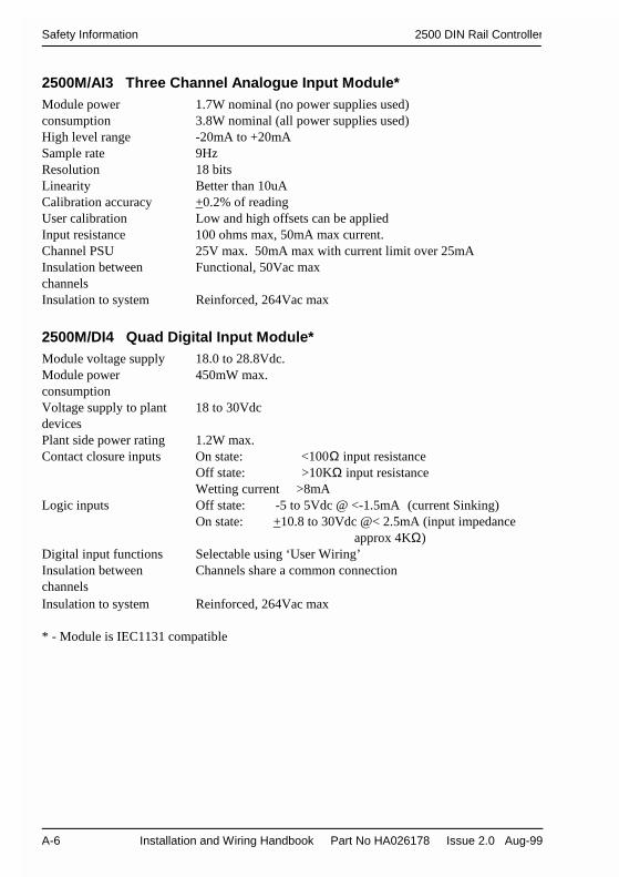
Safety Information 2500 DIN Rail Controller
A-6 Installation and Wiring Handbook Part No HA026178 Issue 2.0 Aug-99
2500M/AI3 Three Channel Analogue Input Module*Module powerconsumption
1.7W nominal (no power supplies used)3.8W nominal (all power supplies used)
High level range -20mA to +20mASample rate 9HzResolution 18 bitsLinearity Better than 10uACalibration accuracy +0.2% of readingUser calibration Low and high offsets can be appliedInput resistance 100 ohms max, 50mA max current.Channel PSU 25V max. 50mA max with current limit over 25mAInsulation betweenchannels
Functional, 50Vac max
Insulation to system Reinforced, 264Vac max
2500M/DI4 Quad Digital Input Module*Module voltage supply 18.0 to 28.8Vdc.Module powerconsumption
450mW max.
Voltage supply to plantdevices
18 to 30Vdc
Plant side power rating 1.2W max.Contact closure inputs On state: <100Ω input resistance
Off state: >10KΩ input resistanceWetting current >8mA
Logic inputs Off state: -5 to 5Vdc @ <-1.5mA (current Sinking)On state: +10.8 to 30Vdc @< 2.5mA (input impedance
approx 4KΩ)Digital input functions Selectable using ‘User Wiring’Insulation betweenchannels
Channels share a common connection
Insulation to system Reinforced, 264Vac max
* - Module is IEC1131 compatible

2500 DIN Rail Controller Safety Information
Installation and Wiring Handbook Part No HA026178 Issue 2.0 Aug-99 A-7
2500M/DI8 Octal Digital Input ModuleModule powerconsumption
0.9W at 24V nominal (logic input)2.34W at 24 V nominal (contact closure input)
Contact closure inputs On state: <100Ω input resistanceOff state: >10KΩ input resistanceWetting current 4mA
Logic inputs Off state: < 5V (current Sinking)On state 10.8 to 30Vdc
Input impedance 5K ohm approx.Digital input functions Selectable using ‘User Wiring’Insulation betweenchannels
Functional isolation between 4 pairs of channels
Insulation to system Reinforced, 264Vac max
2500M/RLY4 Quad Relay Output ModuleModule powerconsumption
1.5W max.
Number of contacts 3 normally open, 1 changeoverMaximum current rating 2A resistive at 240Vac or 120Vdc nominalMinimum ratings 100mA, 12Vdc resistiveInsulation betweenchannels
Functional, 264Vac max.
Insulation to system Reinforced, 264Vac max
2500M/DO4 Quad Digital Output Module (Logic)*Module voltage supply 18.0 to 28.8Vdc.Module powerconsumption
500mW max.
Voltage supply to plantdevices (Vs)
18 to 30Vdc
Plant side power rating 2.5W max.Current output 8mA, (each channel) minimum 16mA maximumOutput voltage >Voltage supply (Vs) less 3VInsulation betweenchannels
Channels share a common connection
Insulation to system Reinforced, 264Vac max
* - Module is IEC1131 compatible

Safety Information 2500 DIN Rail Controller
A-8 Installation and Wiring Handbook Part No HA026178 Issue 2.0 Aug-99
2500M/DO4 Quad Digital Output Module* (24V Output)Module voltage supply 18.0 to 28.8Vdc.Module powerconsumption
500mW max.
Voltage supply to plantdevices (Vs)
12 to 30Vdc
Plant side power rating 15W max.Current output 100mA, (each channel) maximumOutput voltage >Voltage supply (Vs) less 3VInsulation betweenchannels
Channels are electrically connected
Insulation to system Reinforced, 264Vac max
2500M/AO2 Dual Analogue Output Module*Module powerconsumption
2.2W max.
Current output 0-20mA, at 12VdcVoltage output 0Vdc to 10Vdc at 5mAMaximum voltage 30VMaximum current 40mAResolution 1 part in 10,000Analogue outputfunctions
Selectable using ‘User Wiring’
Insulation betweenchannels
Functional, 264Vac max.
Insulation to system Reinforced, 264Vac max
* - Module is IEC1131 compatible

2500 DIN Rail Controller Safety Information
Installation and Wiring Handbook Part No HA026178 Issue 2.0 Aug-99 A-9
AlarmsNumber of alarms 4 per loop, 2 per input and 4 userAlarm types High, low, deviation high, deviation low, deviation band, rate of
changeAlarm modes Latching or non-latching. Blocking.
Energised or de-energised in alarm
CommunicationsModbus RTU 3-wire RS232 RJ11 configuration (intended for configuration
purposes only), 2 and 4-wire RS485 (2 x RJ45), (sometimesreferred to as 3 and 5 wire).
Profibus DP High speed RS485. Up to 12Mb/s
User WiringUser variables 8 real valuesAnalogue function blocks Add, subtract, multiply, divide, absolute difference, maximum
minimum, hot swap, sample and hold, power, square root, Log,Ln, exponential.
Digital function blocks AND, OR, XOR, latch, equal, not equal, greater than, less than,greater than or equal to, less than or equal to.
Wireable analogue PIDparameters
19 per PID control block
Wireable digital PIDparameters
15 per PID control block
General2500 voltage supply 18.0 to 28.8Vdc.System powerconsumption
90W max.
2500P Power Supply Switched 125Vac or 240Vac -15% +10%:24Voutput
Operating ambient 0 to 55OC and 5 to 95% RH non-condensingStorage temperature -10 to +70OCEMC standards Meets generic emissions standards EN50081-2 and
immunity standard EN50082-2 for industrial environmentsSafety standards Meets EN61010, installation category II, pollution degree 2

Safety Information 2500 DIN Rail Controller
A-10 Installation and Wiring Handbook Part No HA026178 Issue 2.0 Aug-99

2500 DIN Rail Controller Understanding the Ordering Codes
Installation and Wiring Handbook Part No HA026178 Issue 2.0 Aug-99 B-1
Appendix B The Ordering Codes
Base Units for 2500 Controller and Modules
Model Description Option 1 Option2 Option 3 Option 4 Language NS Number
2500B Base for the 2500 DIN Rail Controller
S04 Single IOC base, 4 module positions
S08 Single IOC base, 8 module positions
S16 Single IOC base, 16 module positions
- - -
NONE No Earthing clamps
CLAMPS Earthing Clamps
ENG English Manuals
FRA French Manuals
GER German Manuals
XXX No Manuals
X NNN
IO Controller
Model Description Option 1 Option2 Option 3 Option 4 Language NS Number
2500C I/O controller for the 2500 DIN Rail Units
S Simplex IO Controller
ACQIO Remote IO acquisition
UW With User Wiring
2LOOP Two local PID blocks
2LOOPUW Two local PID blocks + user wiring
MODBUS Modbus communications
PROFIBUS Profibus DP comms
- -
ENG English Manuals
FRA French Manuals
GER German Manuals
XXX No Manuals
X NNN
All items in ITALICS - please refer to the factory for availability.

Understanding the Ordering Codes 2500 DIN Rail Controller
B-2 Installation and Wiring Handbook Part No HA026178 Issue 2.0 Aug-99
Modules for 2500 DIN Rail Controller
Model Description Option 1 Option2 Option 3 Option 4 Language NSNumber
2500M I/O modules for the 2500 DIN Rail Controller
AI2 UNIV Dual isolated Universal analogue input module
AI3 3 Channel isolated 4-20mA analogue input with 3 isol. 24V power supply
2500M AO2 UNIV Dual isolated analogue output module, mA or Volts
2500M DI424V Quad digital input module24V DC input (bipolar and includingcontact closure) (EN61131 compliant)
DI4AC240DI4AC120
Quad digital input module 240V ac inputQuad digital input module 120V ac input
-
EXTPWR External Power required
SELFPWR 24v internal PSU (24V only)
2500M DI8logic Octal digital input module,24V DC logic input only (unipolar)
DI8contact Octal digital input module, contact input only
-
2500M DO4 LOGIC Quad digital output module Logic O/P 10mA max
DO424V Quad digital output module Logic O/P 24V switched O/P
-
EXTPWR External Power required
SELFPWR 24v internal PSU (24V only)
-
2500M RLY4 4 relay module (3 off n/o, 1 change over)
- - - -
ENG English Manuals
etc
X NNN
All items in ITALICS - please refer to the factory for availability.

2500 DIN Rail Controller Understanding the Ordering Codes
Installation and Wiring Handbook Part No HA026178 Issue 2.0 Aug-99 B-3
Terminal Units for 2500 I/O Modules
Model Description Option 1 Option2 Option 3 Option 4 Language NS Number
2500T Terminal Units for the modules on the 2500 DIN rail Controller
IOC Terminal Unit for the I/O Controller
S For the Single Controller
R For 1 or 2 Redundant Controllers
MODBUS Modbus Communications
PROFIBUS Profibus Communications
RJ45 RJ45 sockets
9PIND 9 pin D connector (Profibus only)
2500T AI2 Terminal Unit for the Dual analogue input module
TC Unit with CJC for t/c, or for dc inputs (no options)
- -
NONE
2500T AI2 DC Unit for dc inputs with options
- -
NONE
SHUNT
Unit for dc (no options)PT100, HiZ inputs5R shunt for mA inputs
DCONNECT Disconnects for V inputs
2500T AI2 TRPSU Unit for transmitters with fuses, shunts and disconnects
- - -
2500T AO2 Terminal Unit for Dual analogue output module
DI4 Terminal Unit for Quad digital Input module
DI8 Terminal Unit for Octal digital input module
DO4 Terminal Unit for Quad digital output module
UNIV For all types
- -
NONE
DCONNECT Disconnects
2500T RLY4 Terminal Unit for Quad relay module
- - -
NOFUSE No fuses
FUSE2A 4 off 2A fuses
Applicable to all Terminal Units
All items in italics – please refer to the factory for availability ENG English Manuals
etc X NNN

Understanding the Ordering Codes 2500 DIN Rail Controller
B-4 Installation and Wiring Handbook Part No HA026178 Issue 2.0 Aug-99
Power Supplies for 2500 DIN Rail Controllers
2500P Din Rail mounting 24V PSU for 2500, fully protected
2A5 60 watt, 2.5 amp
5A0 120watt, 5 amp
10A 240Watt, 10 amp
- - - -
ENG English Manuals
etc
X NNN
Accessories for 2500 DIN Rail Controllers
2500A Accessories for 2500
CABLE Communications cable
CONFIG Used for configuration of 2500C
RJ11 Termination for 2500C is RJ11
9PINDF Termination for PC is 9 PIN D RS232
3M0 3 metres long
2500A CABLE MODBUS ModBus screened cable (Base to base multidrop connection).
PROFIBUS Profibus DP screened cable (Base to base multidropconnection).RJ45 RJ45 RJ45 connectors both ends
0M5 0.5m long
3M0 3.0 metres long
2500A CFGPSU 24V PSU for use with configuration lead
NONE No mains lead
UKLEAD UK 5A mains lead
2500A TERM Terminator for end of RS 485 multidropped link.
MODBUS Terminator for Modbus link
PROFIBUS Terminator for Profibus DP link
RJ45 RJ45 connector
All items in ITALICS - please refer to the factory for availability.

2500 DIN Rail Controller To Remove Snubber Circuits
Installation and Wiring Handbook Part No HA026178 Issue 2.0 Aug-99 C-1
Appendix C To Remove Snubber Circuits FromThe Relay Module
Each relay is fitted with a ‘snubber’ (22nF + 100Ω) wired across the contacts. The snubbersare used to prolong contact life and to suppress interference particularly when switchinginductive loads such as mechanical contactors and solenoid valves.Snubbers pass a small current typically 1.0mA at 110V 60Hz and 1.7mA at 240V 50Hz,which may be sufficient to hold in high impedance loads as, for example, found in some relaycoils.If this is found to be the case, the snubber can be removed by cutting all or any one of thesnubber resistors from the printed circuit board.
The procedure below may be followed
1. Remove the rear cover from the module:
Figure C-1: Removing the Rear Cover from the Relay Module
1. Open the module retaining lever
2. Gently ease the rear cover out of the module byinserting a small screwdriver in the slots ① at the topand bottom of the cover
3. Gently ease the rear cover over the module retainingcatch. It may be necessary to use the screwdriver inpositions ② to gently lever the cover over the catch.
①
①
②
②

Introduction 2500 DIN Rail Controller
C-2 Installation and Wiring Handbook Part No HA026178 Issue 2.0 Aug-99
2. Remove the printed circuit board from module case as follows:
Figure C-2: Removing the Case from the Relay Module
3. Remove the snubber resistors
Figure C-3: Removing Snubbers from the Relay Module PCB
1. Invert the module andsupport it securely on abench or table top
2. Squeeze the sides of themodule so that the edge ofthe module bows outwards
3. Very carefully insert ascrewdriver into the slotin the edge of themodule.
Take care that thescrewdriver does not slipwhich may cause injury
4. Gently ease the PCB outof module case.
5. Using a suitable pair of wirecutters, snip out and remove the100Ω resistor to remove therequired snubber circuit.
6. Record the removal of the snubberresistor on the side of the module inthe place provided. This willprovide easy identification of whichsnubbers have been removed in theevent that the module needs to bereplaced.
100Ω
100Ω
100Ω
100Ω
22n
22n
22n
22n
Relay 1
Relay 2
Relay 3
Relay 4To connector
block
100ΩSN4
SN1
SN3
SN2

2500 DIN Rail Controller Glossary of Terms
Installation and Wiring Handbook Part No HA026178 Issue 2.0 Aug-99 D-1
Appendix D Glossary of Terms
Config Short for configuration or configuration mode
Config Mode A security level in the 2500 in which Configuration Mode Parametersare made alterable
Configuration 1. The operation and inter-action of the 2500 functional elements
2. The act of defining the operation and inter-action of the 2500functional elements by means of selecting parameters and adjustingparameter values
Config ModeParameters
A subset of the configuration parameters which can only be altered inConfig Mode.
NB c.f. configuration parameters
ConfigurationParameter
A parameter which defines part of the Configuration of the 2500
NB c.f. config mode parameters
Configuration Port A comms port intended for configuration of the 2500
CJC Cold Junction Compensation
Series 2000 or 240x Eurotherm Controls instrument range. 240x refers particularly to the2400 range.
DIN Deutsche Industrie Normand
EM Electro-magnetic, as in EMC ~ Compliance
On/Off control The control output switches on when the setpoint is above processvariable and off when the setpoint is below
Hysteresis The difference between the on and off points normally applied to anoutput relay. Used to prevent relay ‘chatter’.
I/O Abbreviation used to mean the Inputs and/or Outputs
ICP Industrial Control Package. This is a combination of the T2900 and2500 DIN rail controller
IOBase The complete mechanical 2500 assembly - DIN rail mount, base etc.
IOBus Internal controller to I/O module interface

Glossary of Terms 2500 DIN Rail Controller
D-2 Installation and Wiring Handbook Part No HA026178 Issue 2.0 Aug-99
IOC Input/output controller
ION Internal low-level input/output network
Parameter A value stored in a database which is accessible via comms.
Parameterised ‘ Made accessible as a parameter
PID Proportional + Integral + Derivative. Also called three term control
Program Provide a list of general instructions to define operation
Programmable Able to be programmed
PSU Power Supply Unit
PRT or RTD Abbreviation for Platinum Resistance Thermometer or ResistanceTemperature Detector
SE Strategy Engine (generic), or specific: the ISE (industrial) and PSE(process)
Snubber A resistor and capacitor in series, connected across relay contacts,used to prolong contact life and reduce interference
SSR Solid State Relay
TBD. To be defined
TC or T/C Abbreviation for thermocouple
Time proportioning The control output (digital) switches with a variable on to off time

2500 DIN Rail Controller Eurotherm Office Addresses
Installation and Wiring Handbook Part No HA026178 Issue 2.0 Aug-99 E-1
Appendix E Eurotherm Office Addresses
EUROTHERM CONTROLS LIMITED
UK SALES OFFICEEurotherm Controls LimitedFaraday Close,DurringtonWorthingWest SussexBN13 3PLEngland
Telephone Sales: +44 (0) 1903 695888Technical: +44 (0) 1903 695777Service: +44 (0) 1903 695444
Fax +44 (0) 1903 695666
Sales and support in over 30 countries worldwideFor countries not listed overleaf enquiries/orders to:
Eurotherm Controls LimitedExport Dept.,Faraday Close,Durrington,WorthingWest Sussex,BN13 3PLEngland
Telephone +44 (0) 1903 268500Fax +44 (0) 1903 265982
Eurotherm Internet Address http://www.eurotherm.co.uk
Future updates of the manual will be available on the Eurotherm web site as above.

Eurotherm Office Addresses 2500 DIN Rail Controller
E-2 Installation and Wiring Handbook Part No HA026178 Issue 2.0 Aug-99
Rua Alfredo Pujol, 1010 - Santana - São Paulo - SP.
SOLITON CONTROLES INDUSTRIAIS LTDA
Tel:11 - 6950-1834 / Fax: 11 - 6979-8980 - e-mail: [email protected]
www.soliton.com.br - e-mail: [email protected]ções sobre programação