Embed Size (px)
Citation preview

23190 DEL LAGO LAGUNA HILLS CA, 92653
TEL (949)770-1160 FAX (949)770-6717
MODEL 171D POWDER FEEDER
OPERATORS MANUAL

1

2
MAXIMUM RATINGS
Input Volts 120vac rms @ 60hz
Input Current 5 amps
Input Pinch Valve Pressure 80-160 psi
Feed Wheel Speed 20.0 rpm
Canister Pressure 40 psi
Weight 150 lbs
Canister Volume 6.5 Liters
Max Flow (standard feed wheel) 133 mL / min
Dimensions 22” x 31” x 46"
3
Table of Contents
Maximum Ratings .................................................................................................................... 2
Table of Contents..................................................................................................................... 3
Section 1: OVERVIEW.............................................................................................................. 4
1.1 Control Elements............................................................................................................ 4
Section 2: OPERATOR INTERFACE........................................................................................ 6
2.1 Using the Operator Interface........................................................................................... 6
2.2 Editing Values................................................................................................................. 6
2.3 Switching Menus ............................................................................................................ 7
2.4 Function Keys................................................................................................................. 7
F1 Control Auto/Manual ........................................................................................................ 7
F3 Tare............................................................................................................................. 7
F5 Charge Disable............................................................................................................... 7
F6 Speed Auto/Manual. ........................................................................................................ 7
F7 Print............................................................................................................................. 7
F8 Alarm Reset................................................................................................................... 7
F9 Cleaning Mode ............................................................................................................... 7
F10 Auto Charge................................................................................................................. 7
2.5 Display Screen ............................................................................................................... 7
2.5.1 Display Screen Items .................................................................................................... 8
2.5.2 Display Screen Controls................................................................................................. 8
2.6 Parameters..................................................................................................................... 9
2.6.1 Run Settings ............................................................................................................... 9
2.6.2 Alarm Settings........................................................................................................... 11
2.6.3 Filter Settings ............................................................................................................ 11
2.6.4 Misc. Settings............................................................................................................ 12
2.6.5 Auto Charge Settings .................................................................................................. 12
2.6.6 Calibration Settings..................................................................................................... 12
2.7 Calibration Screen ........................................................................................................ 14
Section 3: GENERAL OPERATION ....................................................................................... 15
3.1 Filling the Canister........................................................................................................ 15
3.2 Operating the Powder Feeder....................................................................................... 15
3.3 Shutting Down the Powder Feeder ............................................................................... 15
Section 4: CLEANING / MAINTENANCE ............................................................................... 16
4.1 Cleaning Instructions .................................................................................................... 16
4.2 Pinch Valve Maintenance ............................................................................................. 17
Section 5: CALIBRATION ...................................................................................................... 18
5.1 Pressure Calibration (Instruction List)................................................................................ 18
5.1.1 Part I: Negative Calibration .......................................................................................... 18
5.1.2 Part II: Positive Calibration ........................................................................................... 18
5.2 Weight Calibration (Instruction List)................................................................................... 18
5.2.1 Part I: Preliminary Calibration ....................................................................................... 18
5.2.2 Part II: Standard Calibration ......................................................................................... 19
5.3 Speed/GPM Input Calibration (Instruction List).................................................................. 19
4
OVERVIEW (1.0)
The 171D Powder Feeder is a dual output volumetric powder feeder designed for accurate and consistent delivery of gas suspended powder in production applications.
The feeder uses a dual chamber feed mechanism to eliminate variations due to changes in the amount of powder in the canister. A precision-pocketed feed wheel volumetrically feeds powder at high and low delivery rates accurately and with high linearity. Pressure at the feed line is equalized with the rest of the canister to eliminate powder backflow. The canister is protected by a 40-psi pressure safety valve. The entire feed mechanism rests on three electronic load cells that measure and control the amount of powder in the canister.
This feeder also operates with a gas bypass system that uses long lasting pneumatic pinch valves to switch gas and powder flows. The bypass system allows the powder canister to isolate the stabilized feed pressure while the feeder is not in use. This system allows instant startup times without having to wait for pressure stabilization between runs. The gas bypass also keeps the powder line free of clogs and prevents back flow from the plasma gun by maintaining a continuous flow of gas through the line. The isolation of the canister also allows the feeder to be filled while the plasma gun is operating in atmosphere or vacuum. The system also includes a venting pinch valve to purge air in the chamber.
The 171D uses a combined programmable logic controller and operator interface terminal to control all functions of the powder feeder. This control module allows for many convenient features which includes full external control, crystal oscillator controlled feed rpm and timing, feed motor vibration, calibration of all analog inputs, feed adjusting based on weight measurements from the load cells, auto-charging of the canister, weight over-limit and powder low alarms, run timeout, cycle counting, and serial output of feeder statistics for data logging.
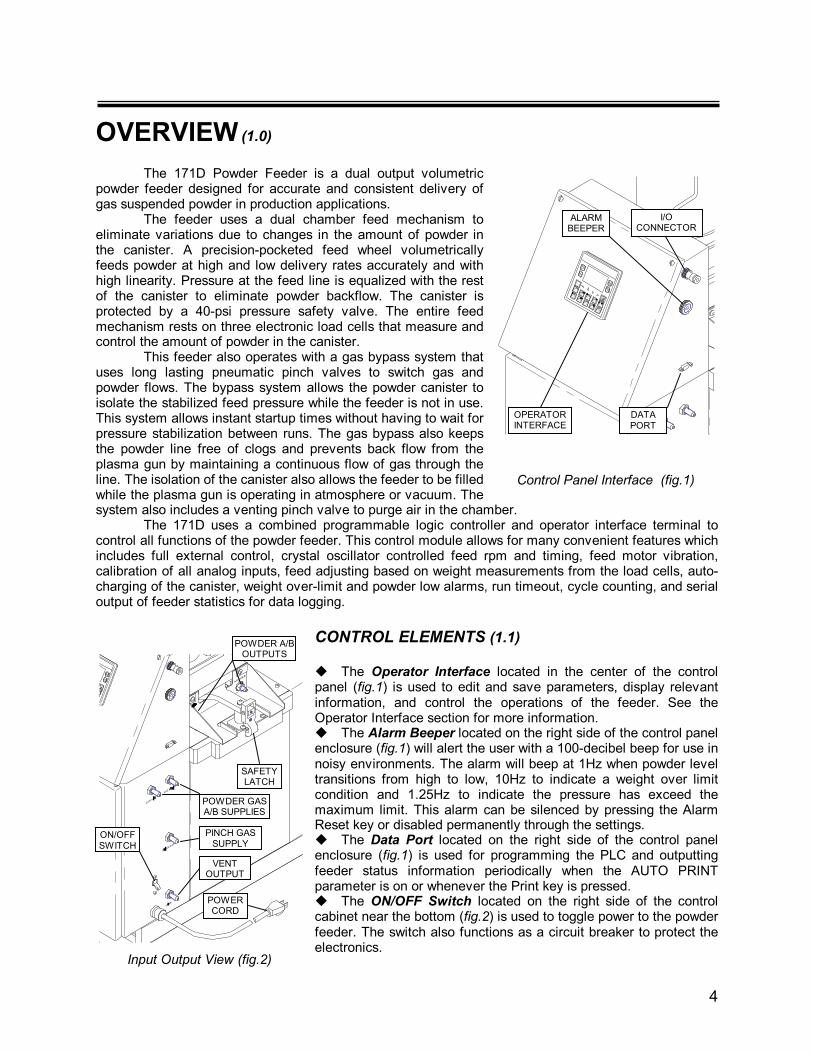
CONTROL ELEMENTS (1.1) The Operator Interface located in the center of the control panel (fig.1) is used to edit and save parameters, display relevant information, and control the operations of the feeder. See the Operator Interface section for more information. The Alarm Beeper located on the right side of the control panel enclosure (fig.1) will alert the user with a 100-decibel beep for use in noisy environments. The alarm will beep at 1Hz when powder level transitions from high to low, 10Hz to indicate a weight over limit condition and 1.25Hz to indicate the pressure has exceed the maximum limit. This alarm can be silenced by pressing the Alarm Reset key or disabled permanently through the settings. The Data Port located on the right side of the control panel enclosure (fig.1) is used for programming the PLC and outputting feeder status information periodically when the AUTO PRINT parameter is on or whenever the Print key is pressed. The ON/OFF Switch located on the right side of the control cabinet near the bottom (fig.2) is used to toggle power to the powder feeder. The switch also functions as a circuit breaker to protect the electronics.
Control Panel Interface (fig.1)
I/O CONNECTOR
ALARM BEEPER
DATA PORT
OPERATOR INTERFACE
Input Output View (fig.2)
VENT OUTPUT
POWER CORD
POWDER A/B OUTPUTS
PINCH GAS SUPPLY
ON/OFF SWITCH
POWDER GAS A/B SUPPLIES
SAFETY LATCH

5
The Power Cord located on the right side of the control cabinet near the bottom (fig.2) powers the system through a stand-ard 110v wall socket.
The Safety Latch located next to the load cell contact furthest from the feed mechanism pivot point (fig.2) prevents the feed mechanism from accidentally falling down on the load cells (fig.5) and damaging them. After pivoting the feed mechanism backwards it can be placed back on the load cells by carefully supporting its weight while flipping the latch away from the frame and then carefully lowering the feed mechanism all the way down.
The Powder Gas A and B Supply input connectors on the right side of the control cabinet near the top (fig.2) supplies carrier gas to both of the powder outputs. This input should be supplied with a mass flow controlled gas supply.
The Pinch Gas Supply input connector located in the middle of the control cabinet (fig.2) supplies the pinch valve pressure. This input must be supplied with 80 – 160 psi.
The Vent Output connector located at the bottom of the control cabinet (fig.2) is the location where pressure is vented from the canister for filling, cleaning, or purging.
The Powder A and B Output connectors located on the powder feeder mechanism (fig.2) are the locations where powder/gas or bypassed gases flow out to the plasma gun.
The I/O Connector located on the right side of the control panel cabinet (fig.1) is an 8-pin connector that uses digital and analog signals to allow for auxiliary control of the powder feeder. The Ground pin (1) connects to the system ground. The Stop pin (2) will stop the feed cycle when high in 2 Wire control mode. The Start pin (3) will start the feed cycle when high in 2 Wire control mode or maintain the feed cycle when high in 1 Wire control mode. The 24v pin (4) provides power to the Stop, Start, Inc- and Inc+ input pins or power for auxiliary control devices. (Current should not exceed 200mA) The Inc- pin (5) decrements the feed speed or gpm rate by the RPM INC and GPM INC values respectively when the pin transitions from low to high. The Inc+ pin (7) increments the feed speed
or gpm rate by the RPM INC and GPM INC values respectively when the pin transitions from low to high. The Sig- and Sig+ pins (8,6) are a floating 0-10V input that is used to specify the feed speed or gpm rate of the powder feeder.
The Pressure Safety Valve located at the top of the canister (fig.3) will release pressure if the canister is charged above 40 psi in order to prevent damage to the window and clamps.
The Window and Window Clamps located at the top of the canister (fig.3) are designed to be quickly removed for powder filling while in operation. When resealing the window turn oppo-sing Window Clamps at the same time to clamp the window evenly. Only tighten the window clamps until the window o-ring is fully compressed.
The Canister Clamp located at the bottom of the canister (fig.5) are designed to quickly disassemble the canister and feed mechanism for cleaning. When reassembling the canister turn opposing Canister Clamps at the same time to clamp the canister evenly. Only tighten the Canister Clamps until the canister o-ring is fully compressed.
Canister Base (fig.5)
CANISTER CLAMP
LOAD CELL
GROUND (1)
STOP (2)
START (3)
24V (4)
(6) SIG+
(7) INC+
(5) INC-
(8) SIG-
Electrical I/O Connector (fig.4)
Canister (fig.3)
PRESSURE SAFETY VALVE
WINDOW CLAMPS
HANDLE
WINDOW

6
OPERATOR INTERFACE (2.0)
PANEL DIAGRAM (fig.6)
USING THE OPERATOR INTERFACE (2.1) The operator interface contains a 132 x 64 pixel backlit LCD display, 4 soft keys, 10 alphanumeric / function keys, directional keypad, escape, and enter keys. Program and configuration memory is backed up in three ways; first by battery backed RAM that retains memory even when power is disconnected, second by internal flash memory for program memory only, and third by an external micro SD card that contains backups of both program and configuration memory. Configuration memory is automatically backed up to the SD card when changed. This interface is used to display feeder status and to edit set points and calibration values that are used by the PLC to control the operations of the feeder.
Editing Values (2.2) In the various menus and display screens whenever a value is surrounded by a dashed line box ( ), this value can be edited with the numeric keypad. The directional keys can be used to select multiple values that are on the same screen. Once the desired value is selected press the Enter key to begin editing. Entry into edit mode will be signaled by inverting the colors of the value ( ). Use the numeric, sign and decimal keys to enter the desired value. If the value being edited is a fixed decimal, integer or text value, then the Up and Down keys can be used to increment or decrement the value. If the value being edited is in scientific notation ( ) first enter the significand using the sign, decimal and numeric keys, then press the decimal key a second time and enter the exponent using the sign and numeric keys. After the new value is entered press the Enter key to update the new value or if the change needs to be canceled press the Escape key. If incorrect or out of range values are entered after pressing the Enter key the parameter will not be updated.
SOFT KEYS
DISPLAY SCREEN
ALPHA-NUMERICAND FUNCTION
KEYPAD
SOFT KEYS
ESCAPE KEYENTER KEY
SIGN KEY
DECIMAL AND EXPONENT KEY
DIRECTIONAL KEYS

7
Switching Menus (2.3)
There are two main screens that are used to navigate, control, and edit the various values and functions of the powder feeder, they are the Display screen and the Settings Screen. At any time the user can press the soft key located on the top left of the operator interface to toggle between Display and Setting screens. While in the Settings screen, menu items can be selected with the Up and Down arrow keys. The first and last items in a settings menu can be selected using the Left and Right arrow keys. After selecting the desired sub menu press the Enter key to display that sub menu. To return to the previous screen press the Escape key. To enter the system menu press the Up and Down Arrow keys simultaneously. When in the system menu all other screens will be disabled. To exit the system menu press the Escape key.
Function Keys (2.4)
When the Display screen is shown and values on the Display screen are not currently being edited, the 10 alphanumeric keys will act as function keys for quick access to features of the feeder. Holding the Escape key will display a legend to help the operator remember the functions of each key.
F1 Control Auto/Manual. Toggles the feed run control state between “auto” which uses the I/O pins 2 and 3 to control the run, and between “manual” which only uses the keypad to control the run. When either mode is selected the other input source is disabled. The current run control state is displayed in a combined message on the display screen labeled Mode (fig.7 item 8).
F2 Unused.
F3 Tare. Zeros out the weight display on the Display screen. If the TARE TIMEOUT value is greater than zero then the feeder will wait for the value stored so that the weight measurement has time to settle. During this timeout period the weight display (fig.7 item 10) will be filled with e’s. Hold this key down for 3 seconds to reset the zero point to the base weight level specified by the BASE WEIGHT parameter.
F4 Unused.
F5 Charge Disable. Temporarily disables the idle pressure maintenance function so the canister can be opened to atmosphere. The maintenance function will resume when the Charge or Feed Start/Stop keys are pressed. The pressure maintenance function can be permanently disabled through the IDLE PRESSURE. parameter.
F6 Speed Auto/Manual. Toggles the speed control state between “auto” which uses the analog I/O pins 6 and 8 to control the feed RPM or GPM and between “manual” which only uses the keypad to enter RPM or GPM values. When either mode is selected the other input source is disabled. The current speed control state is displayed in a combined message on the display screen labeled Mode (fig.7 item 8).
F7 Print. Manually outputs feeder status data through the data port whenever pressed.
F8 Alarm Reset. Resets the powder low alarm beeper and flashing screen when pressed. This key is also used to complete calibration in the calibration screen.
F9 Cleaning Mode. Toggles the cleaning mode state of the feeder. When cleaning mode is on the "Mode" display (fig.7 item 8) on the Display screen will flash "CLEANING".
F10 Auto Charge. Initiates an auto charge cycle. The cycle starts by opening the vent valve and waiting for canister pressure to fall below the value stored in the TIMEOUT PRESSURE parameter. The cycle will continue to vent for the period specified by the VENT TIMEOUT parameter and the timer display(fig.7 item 9) will count down the timeout. Afterwards the vent will close and the canister will be charged until it reaches the pressure value stored in the CHARGE PRESSURE parameter. The venting portion of the cycle can be skipped if the TIMEOUT PRESSURE value is set to 50.0 and the VENT TIMEOUT value is 0. This key is disabled while the feeder is running. When pressed during an auto charge cycle this key will cancel the auto charge cycle.
Display Screen (2.5)
The display screen (fig.7) is used to display all relevant information for the monitoring and control of the powder feeder. The 4 buttons (1-4) on the left and right of the display correspond to the action of the surrounding soft keys as well as indicators of the current state of the feeder. The three modifiable values (5-7) in the upper middle of the display allow for the operator to quickly change those set points as well as displaying their current value. The four display only values (8-11) show the current status of the feeder. Display Screen (fig.7)
1
3
2
4
5 6
10 11
8 9
7
8
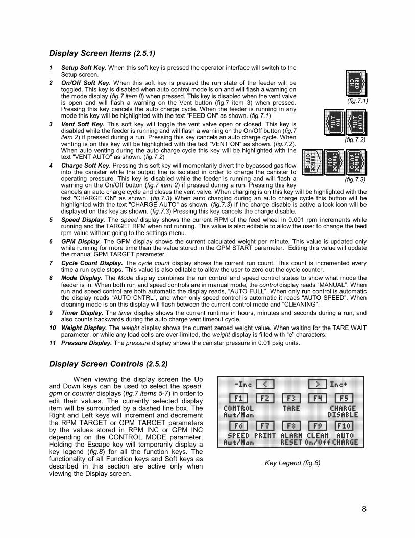
Display Screen Items (2.5.1) 1 Setup Soft Key. When this soft key is pressed the operator interface will switch to the
Setup screen.
2 On/Off Soft Key. When this soft key is pressed the run state of the feeder will be toggled. This key is disabled when auto control mode is on and will flash a warning on the mode display (fig.7 item 8) when pressed. This key is disabled when the vent valve is open and will flash a warning on the Vent button (fig.7 item 3) when pressed. Pressing this key cancels the auto charge cycle. When the feeder is running in any mode this key will be highlighted with the text "FEED ON" as shown. (fig.7.1)
3 Vent Soft Key. This soft key will toggle the vent valve open or closed. This key is disabled while the feeder is running and will flash a warning on the On/Off button (fig.7 item 2) if pressed during a run. Pressing this key cancels an auto charge cycle. When venting is on this key will be highlighted with the text "VENT ON" as shown. (fig.7.2). When auto venting during the auto charge cycle this key will be highlighted with the text "VENT AUTO" as shown. (fig.7.2)
4 Charge Soft Key. Pressing this soft key will momentarily divert the bypassed gas flow into the canister while the output line is isolated in order to charge the canister to operating pressure. This key is disabled while the feeder is running and will flash a warning on the On/Off button (fig.7 item 2) if pressed during a run. Pressing this key cancels an auto charge cycle and closes the vent valve. When charging is on this key will be highlighted with the text "CHARGE ON" as shown. (fig.7.3) When auto charging during an auto charge cycle this button will be highlighted with the text "CHARGE AUTO" as shown. (fig.7.3) If the charge disable is active a lock icon will be displayed on this key as shown. (fig.7.3) Pressing this key cancels the charge disable.
5 Speed Display. The speed display shows the current RPM of the feed wheel in 0.001 rpm increments while running and the TARGET RPM when not running. This value is also editable to allow the user to change the feed rpm value without going to the settings menu.
6 GPM Display. The GPM display shows the current calculated weight per minute. This value is updated only while running for more time than the value stored in the GPM START parameter. Editing this value will update the manual GPM TARGET parameter.
7 Cycle Count Display. The cycle count display shows the current run count. This count is incremented every time a run cycle stops. This value is also editable to allow the user to zero out the cycle counter.
8 Mode Display. The Mode display combines the run control and speed control states to show what mode the feeder is in. When both run and speed controls are in manual mode, the control display reads “MANUAL”. When run and speed control are both automatic the display reads, “AUTO FULL”. When only run control is automatic the display reads “AUTO CNTRL”, and when only speed control is automatic it reads “AUTO SPEED”. When cleaning mode is on this display will flash between the current control mode and "CLEANING".
9 Timer Display. The timer display shows the current runtime in hours, minutes and seconds during a run, and also counts backwards during the auto charge vent timeout cycle.
10 Weight Display. The weight display shows the current zeroed weight value. When waiting for the TARE WAIT parameter, or while any load cells are over-limited, the weight display is filled with “e” characters.
11 Pressure Display. The pressure display shows the canister pressure in 0.01 psig units.
Display Screen Controls (2.5.2) When viewing the display screen the Up and Down keys can be used to select the speed, gpm or counter displays (fig.7 items 5-7) in order to edit their values. The currently selected display item will be surrounded by a dashed line box. The Right and Left keys will increment and decrement the RPM TARGET or GPM TARGET parameters by the values stored in RPM INC or GPM INC depending on the CONTROL MODE parameter. Holding the Escape key will temporarily display a key legend (fig.8) for all the function keys. The functionality of all Function keys and Soft keys as described in this section are active only when viewing the Display screen.
(fig.7.2)
(fig.7.1)
(fig.7.3)
Key Legend (fig.8)
9
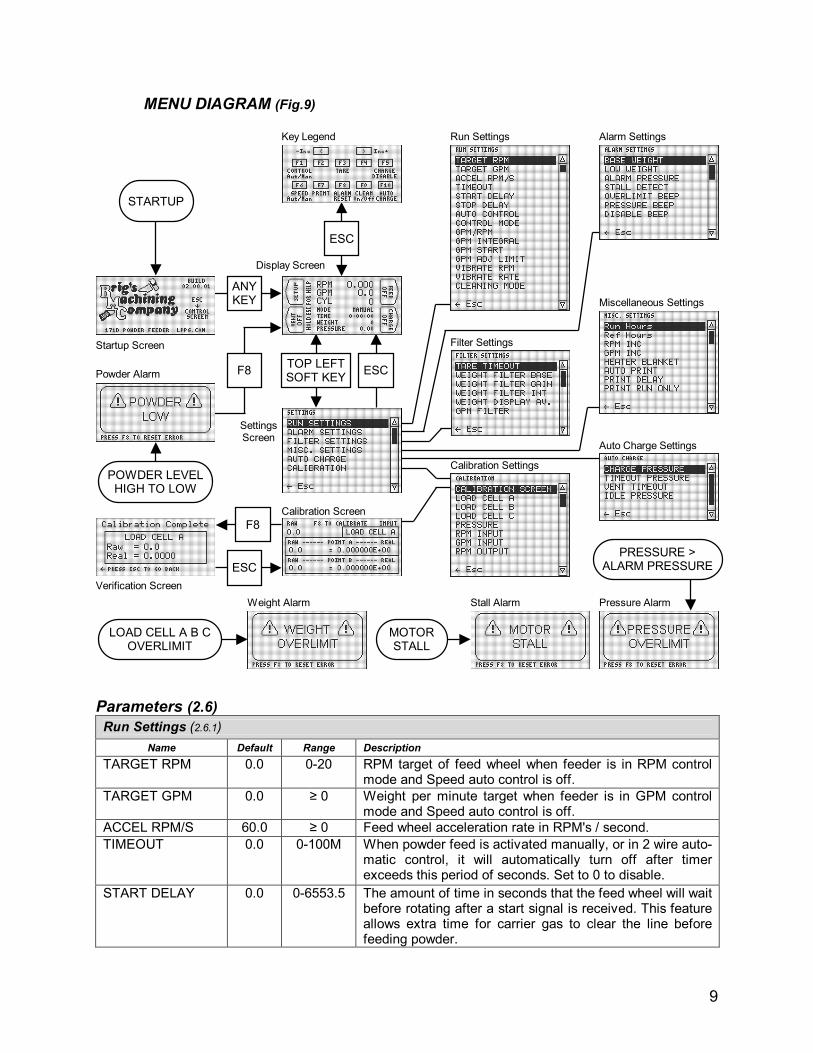
MENU DIAGRAM (Fig.9)
Parameters (2.6)
Run Settings (2.6.1)
Name Default Range Description
TARGET RPM 0.0 0-20 RPM target of feed wheel when feeder is in RPM control mode and Speed auto control is off.
TARGET GPM 0.0 ≥ 0 Weight per minute target when feeder is in GPM control mode and Speed auto control is off.
ACCEL RPM/S 60.0 ≥ 0 Feed wheel acceleration rate in RPM's / second.
TIMEOUT 0.0 0-100M When powder feed is activated manually, or in 2 wire auto-matic control, it will automatically turn off after timer exceeds this period of seconds. Set to 0 to disable.
START DELAY 0.0 0-6553.5 The amount of time in seconds that the feed wheel will wait before rotating after a start signal is received. This feature allows extra time for carrier gas to clear the line before feeding powder.
Verification Screen
Powder Alarm
Weight Alarm Stall Alarm Pressure Alarm
Settings Screen
Calibration Screen
Calibration Settings
Startup Screen
Display Screen
Key Legend Run Settings Alarm Settings
Filter Settings
Miscellaneous Settings
Auto Charge Settings
STARTUP
ANY KEY
ESC
TOP LEFT SOFT KEY
F8
ESC
POWDER LEVEL HIGH TO LOW
F8 ESC
LOAD CELL A B C OVERLIMIT
MOTOR STALL
PRESSURE > ALARM PRESSURE

10
Run Settings continued (2.6.1)
Name Default Range Description
STOP DELAY 0.0 0-6553.5 The amount of time in seconds that the carrier gas will continue to flow after a stop signal is received. This feature allows extra time for carrier gas to clear the line of powder after a run has completed.
AUTO CONTROL 1Wire 1Wire 2Wire
This parameter is used to select the external run control mode. When this value is “1Wire” automatic runs are controlled through a single I/O pin (3). In this mode the feeder will run when pin 3 is high and stop when pin 3 is low. When the value is “2Wire” automatic runs are controlled through I/O pins 2 and 3. In this mode the feeder will start when pin 3 transitions from low to high, and stop when pin 2 transitions from low to high.
CONTROL MODE RPM RPM GPM
This parameter is used to select the method of control for the feed wheel speed. When “RPM” is selected the feed wheel speed will be directly controlled by the TARGET RPM value in manual speed mode, and the external analog input in automatic speed mode. When “GPM” is selected the output rpm is constantly adjusted to match the calculated GPM to the TARGET GPM in manual speed mode, and to the external analog input in automatic speed mode.
GPM/RPM 30.0 0-10M This parameter is used in GPM control mode to define the rough grams per minute that are outputted for every rpm of the feed wheel. This value allows instantaneous adjusting when new GPM targets are inputted. This value will vary according to different powder densities, particle sizes and gas flow rates.
GPM INTEGRAL 0.001 ≥ 0 The amount of acceleration in RPM of the feed wheel speed for the measured GPM error added every 100ms. In GPM control mode this value is used as an integral adjustment of the RPM to match the output GPM to the target GPM.
GPM START 5.0 0-429M The amount of time in seconds after a feed run starts when GPM calculations and adjustments will begin while running in GPM mode. This value is used to ignore initial fluctuations in weight at the beginning of the feed run.
GPM ADJ LIMIT 1.0 ≥ 0 The maximum RPM adjusting limit when using GPM control. The output RPM will not vary more than this value from the base RPM calculated by dividing TARGET GPM by the GPM/RPM parameter.
VIBRATE RPM 0.0 ≥ 0 The motor vibration amount in RPM. When this parameter is set to 0.0 vibration is disabled. The vibration will raise and lower the target RPM by the amount specified on a %50 duty cycle with a period defined by the VIBRATE RATE parameter while still maintaining average target rpm.
VIBRATE RATE 20 0-200 Period in milliseconds for RPM vibration adjustment.
CLEANING MODE Off Off On
Toggles the cleaning mode feature on and off. When On carrier gas is disabled during run cycles. This allows the canister to be opened to atmosphere while running the feed wheel in order to recover powder from the mechanism while still attached to a system under vacuum. WARNING! Only run in cleaning mode while the canister is upside down, otherwise powder clogging may occur.

11
Alarm Settings (2.6.2)
Name Default Range Description
BASE WEIGHT 0.0 ±1G the permanent zero point, for the total weight of the feeder mechanism without any powder weight added. When the TARE button is held for 3 seconds the weight display will zero out at this value
LOW WEIGHT 1000 ±1G The amount of weight above the BASEWEIGHT in grams that the user considers to be a low powder level. This value is used to trip the low powder alarm. Set to negative to disable.
ALARM PRESSURE
30.0 ±100K Feeder will alarm when pressure exceeds this value. Set to maximum canister pressure to disable.
STALL DETECT Off Off On
When a motor proximity switch is installed on the feeder this parameter is used to enable the stall alarm when the motor spindle feedback does not detect rotation.
OVERLIMIT BEEP Yes No Yes
When this parameter is set to “Yes” the feeder will give an audible beep warning when any load cells are over-limited.
PRESSRE BEEP Yes No Yes
This parameter is used to disable the audible beep alarm when canister pressure is above the alarm pressure limit defined by ALARM PRES. When “Yes” is selected the audible alarm is pressure alarm is enabled. Setting “No” will not disable the display alarm.
DISABLE BEEP No No Yes
This parameter is used to disable the audible beep alarm when the powder level transitions from high to low. When “Yes” is selected the audible alarm is disabled for the powder alarm but not the flashing display alarm. Setting “No” will not disable the weight over-limit alarm, both display or sound.
Filter Settings (2.6.3)
Name Default Range Description
TARE TIMEOUT 1.0 0-6553.5 The amount of time in seconds the feeder waits before zeroing the weight display after pressing the tare key. Zeroing samples are taken midway through the timeout. To disable the wait, set this value to 0.0.
WEIGHT FILTER BASE
.0001 0-1 Weight input alpha filter base value. Represents the finest sensitivity for load cell input. Larger values increase response to changes in weight.
WEIGHT FILTER GAIN
0.5 ≥ 0 Proportional gain to alpha filter for unit weight error. Larger values increase response to changes in weight.
WEIGHT FILTER INT
0.5 ≥ 0 Integral gain to alpha filter for unit weight error every 100ms. Larger values increase response.
WEIGHT DISPLAY AV.
0.1 0-1 Final Pass alpha filter for weight display only. Smaller values increase accuracy. Larger value increase response.
GPM FILTER 0.1 0-1 Final Pass alpha filter for GPM input. Smaller values increase accuracy. Larger value increase response.
Note: Every 10ms the WEIGHT Value is updated with the following equation: INTEGRAL = INTEGRAL + (FILT_INT • WEIGHT_ERR • 0.01) FILTER = FILT_BASE • (1.0 + FILT_GAIN • WEIGHT_ERR + INTEGRAL) Weight = Weight • (1.0 - FILTER) + RAW_WEIGHT • FILTER Weight Dis. = Weight Dis•(1.0- WEIGHT DISPLAY AV.)+ Weight • WEIGHT DISPLAY AV Every 100ms the GPM Value is updated with the following equation: GPM = GPM • (1 - GPM_FILT) + RAW_GPM • GPM_FILT

12
Misc. Settings (2.6.4)
Name Default Range Description
Run Hours Read Only
0-429M Total runtime in hours for maintenance reference.
Ref Hours N/A
0-429M User settable runtime accumulator in hours for maintenance reference.
RPM INC 1.0 ±100K The incremental change, either positive or negative, of the RPM target when the I/O pins 5 and 7 go from low to high, or when the right and left keys are pressed in the display screen. This value only applies when the feeder is in RPM control mode.
GPM INC 1.0 ±100K The incremental change, either positive or negative, of the GPM target when the I/O pins 5 and 7 go from low to high, or when the right and left keys are pressed in the display screen. This value only applies when the feeder is in GPM control mode.
HEATER BLANKET
Off Off On
Sets the heater blanket on and off if installed on the feeder.
AUTO PRINT Off Off On
Turns the auto print feature on and off. When this parameter is set on the feeder will output statistics serially according to the PRINT RUN ONLY and PRINT DELAY parameters.
PRINT DELAY 1.0 0-6553.5 Defines the AUTO PRINT period in seconds
PRINT RUN ONLY No No Yes
This parameter is used while in AUTO PRINT mode to output feeder statistics while the feeder is not running. “Yes” will output feeder statistics only while the feeder is running, and “No” will output feeder statistics all the time.
Auto Charge Settings (2.6.5)
Name Default Range Description
CHARGE PRESSURE
3.0 ±1M Defines the auto charge cycle target charge pressure. After the auto charge venting cycle defined by TIMEOUT PRESSURE and VENT TIMEOUT, the feeder will automatically charge the canister until the pressure exceeds CHARGE PRESSURE. at which point the auto charge cycle will end.
TIMEOUT PRESSURE
-13.0 ±1M Defines the lower pressure limit in where the venting timeout portion of the auto charge cycle will begin. To disable the waiting portion of the auto charge cycle set this parameter above maximum canister pressure.
VENT TIMEOUT 60.0 0-429M Defines the venting timeout period in seconds that the auto charge cycle will wait while venting the canister before beginning the charge cycle. To disable the time out set this parameter to 0.0.
IDLE PRESSURE -15.0 ±1M Defines the pressure that the feeder will actively maintain in the canister while not feeding. The idle pressure feature can be temporarily disabled using the charge disable key (F5). Enter an unattainable negative value to disable this feature permanently.
Calibration Settings (2.6.6)
Name Default Range Description
CALIBRATION SCREEN N/A N/A
Pressing the enter key on this item will display the calibration screen. The calibration screen is used to calculate calibration values. See section 2.7
13
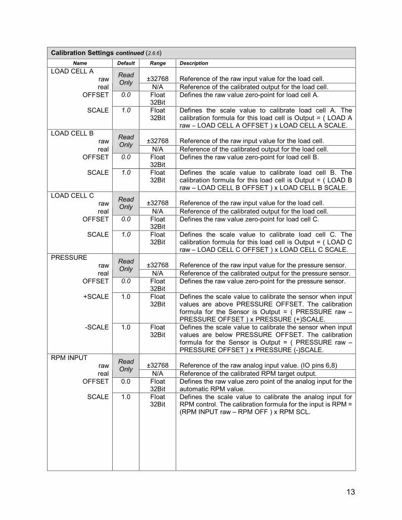
Calibration Settings continued (2.6.6)
Name Default Range Description
LOAD CELL A
raw
±32768
Reference of the raw input value for the load cell.
real
Read Only
N/A Reference of the calibrated output for the load cell.
OFFSET 0.0 Float 32Bit
Defines the raw value zero-point for load cell A.
SCALE 1.0 Float 32Bit
Defines the scale value to calibrate load cell A. The calibration formula for this load cell is Output = ( LOAD A raw – LOAD CELL A OFFSET ) x LOAD CELL A SCALE.
LOAD CELL B
raw
±32768
Reference of the raw input value for the load cell.
real
Read Only
N/A Reference of the calibrated output for the load cell.
OFFSET 0.0 Float 32Bit
Defines the raw value zero-point for load cell B.
SCALE 1.0 Float 32Bit
Defines the scale value to calibrate load cell B. The calibration formula for this load cell is Output = ( LOAD B raw – LOAD CELL B OFFSET ) x LOAD CELL B SCALE.
LOAD CELL C
raw
±32768
Reference of the raw input value for the load cell.
real
Read Only
N/A Reference of the calibrated output for the load cell.
OFFSET 0.0 Float 32Bit
Defines the raw value zero-point for load cell C.
SCALE 1.0 Float 32Bit
Defines the scale value to calibrate load cell C. The calibration formula for this load cell is Output = ( LOAD C raw – LOAD CELL C OFFSET ) x LOAD CELL C SCALE.
PRESSURE
raw
±32768
Reference of the raw input value for the pressure sensor.
real
Read Only
N/A Reference of the calibrated output for the pressure sensor.
OFFSET 0.0 Float 32Bit
Defines the raw value zero-point for the pressure sensor.
+SCALE 1.0 Float 32Bit
Defines the scale value to calibrate the sensor when input values are above PRESSURE OFFSET. The calibration formula for the Sensor is Output = ( PRESSURE raw – PRESSURE OFFSET ) x PRESSURE (+)SCALE.
-SCALE 1.0 Float 32Bit
Defines the scale value to calibrate the sensor when input values are below PRESSURE OFFSET. The calibration formula for the Sensor is Output = ( PRESSURE raw – PRESSURE OFFSET ) x PRESSURE (-)SCALE.
RPM INPUT
raw
±32768
Reference of the raw analog input value. (IO pins 6,8)
real
Read Only
N/A Reference of the calibrated RPM target output.
OFFSET 0.0 Float 32Bit
Defines the raw value zero point of the analog input for the automatic RPM value.
SCALE 1.0 Float 32Bit
Defines the scale value to calibrate the analog input for RPM control. The calibration formula for the input is RPM = (RPM INPUT raw – RPM OFF ) x RPM SCL.

14
Calibration Settings continued (2.6.6)
Name Default Range Description
GPM INPUT
raw
±32768
Reference of the raw analog input value. (IO pins 6,8)
real
Read Only
N/A Reference of the calibrated GPM target output.
OFFSET 0.0 Defines the raw value zero point of the analog input for the automatic GPM value.
SCALE 1.0 Defines the scale value to calibrate the analog input for GPM control. The calibration formula for the input is GPM = (GPM INPUT raw – GPM OFF ) x GPM SCL.
RPM OUTPUT
OFFSET
0.0
Float 32Bit
Voltage to frequency analog output zero point for motor speed control. 0-32000 = 0-10V.
SCALE 1.0 Float 32Bit
Voltage to frequency analog output scale for motor speed control. Voltage output = RPM x RPM OUTPUT SCALE + RPM OUTPUT OFFSET. This parameter should be calibrated so that 0-10V = 0-50kHz, where 0-32000 roughly equals 0-10v.
Calibration Screen (2.7)
The calibration screen (fig.10) is used to quickly calculate and save the offset and scale parameters for the various calibration settings of the powder feeder. The Item value is used to select the input source to be calibrated by pressing the enter key and using the up and down keys. “LOAD CELL A” is the input source calibration for load cell A, the load cell nearest the control cabinet next to the pivot point. “LOAD CELL B” is the input source calibration for load cell B, the load cell furthest from the control cabinet next to the pivot point. “LOAD CELL C” is the input source calibration for load cell C, the load cell next to the safety latch (fig.2). “+PRESSURE” is the input source calibration for the pressure transducer when reading values above atmosphere. “-PRESSURE” is the input source calibration for the pressure transducer when reading values below atmosphere. “RPM INPUT” is the input source calibration for the 0-10v input when being used to externally control RPM. “GPM INPUT” is the input source calibration for the 0-10v input when being used to externally control GPM. “WEIGHT” is the combined input source of all three load cells used for a standard weight calibration (see WEIGHT CALIBRATION instruction list). The Raw value is not editable, and is used to display the current raw value of the selected input source.
The calibration screen needs two calibration points to calculate the offset and scale values for the selected input source. To do this enter the raw value and its corresponding real value for points A and B. Use directional keys to select the Raw A, Real A, Raw B and Real B fields and enter the appropriate values. When all values are entered press the Alarm Reset key F8 to calculate and save the calibration values. When the calibration calculation is complete the interface will switch to the completed screen. This screen will display the raw value and calibrated value to verify that calibration has been updated successfully. To return to the calibration screen for further calibration press the Escape key.
Calibration Screen (fig.10)
ITEM RAW
RAW A
RAW B
REAL A
REAL B
ITEM
RAW
REAL

15
GENERAL OPERATION (3.0)
FILLING THE CANISTER (3.1)
1. The 171D powder feeder is capable of being filled while still connected to a plasma gun that is in operation. In order to refill the canister during operation first make sure the powder feeder is not running, charging or venting.
2. Check the pressure display to see if the canister pressure is at atmosphere. If the pressure is above atmosphere use the powder feeders vent function to lower the pressure. If the pressure is below atmosphere pull up on the pressure safety valve (fig.3) or preferably, manually charge the feeder to allow pressure into the canister (Do not pull up on the pressure safety valve if the pressure inside the canister is greater than atmosphere, this may lead to powder degrading the seal causing an air leak). Press the Charge Disable key if idle pressure maintenance is used.
3. After pressure is equalized and the canister is isolated, unscrew and remove the Window Lid (fig.3) (Do not attempt to unscrew the window lid if pressure inside the canister is greater than atmosphere, as this may result in damage to the window clamps).
4. Fill the canister with powder then replace and secure the Window Lid making sure the top lip of the canister and o-ring surfaces of the lid are clean. Be careful not to fill the canister above the level where the pressure safety valve and equalizing tube fittings (fig.3) enter the top of the canister. This may result in damage to the pressure safety valve or clogging of the equalizing line causing unstable powder flows.
OPERATING THE POWDER FEEDER (3.2)
1. If the powder gas must be purged before spraying, turn the vent on and use the pressure display to see when the canister has been pulled down to vacuum. Wait for the desired amount of time for the air in the canister to be purged by a sufficient amount for the spray process. Afterwards use the powder feeders charge function to backfill the canister to the “operating pressure”. The feeder’s auto charge function can be used to automatically complete this process. If purging is unnecessary skip the venting process.
2. The “operating pressure” is determined by the powder gas mass flow rate, type of powder, feed wheel speed, powder line length, and plasma gun backpressure. In order for the powder feeder to operate with instant-on times during the spray cycle the canister must remain at the stabilized “operating pressure”. To determine the “operating pressure” run the spray cycle with all desired settings at stable positions (powder gas flow rate, feed wheel speed, plasma arc power, plasma arc gas flow rate and plasma chamber pressure) and watch the pressure display as the canister pressure stabilizes.
3. Once the canister is charged to “operating pressure” the feeder can be turned off and on man-ually or automatically during the spray cycle of the plasma system.
4. If dry runs are required while operating in auto mode, the powder feeder can be disabled by toggling the control mode to manual by pressing the Auto/Manual Control key (F1).
SHUTTING DOWN THE POWDER FEEDER (3.3)
1. When shutting down the powder feeder the default state of the pinch valves is venting open, output line isolated and the carrier gas is bypassed. As long as pinch gas pressure remains above 80 psi even when power is off the powder feeder will remain in this state. Otherwise to isolate the canister after the end of operations power and pinch gas pressure must be maintained. If pinch gas pressure is lost after shutdown both venting and powder output valves will open releasing any canister pressure into the plasma system. All settings in the interface module are saved when updated so they are not lost when power is removed.

16
Feed Mechanism Assembly (fig.11)
MAIN PLATE
WINDOW LID
AGITATOR
LOAD WHEEL COVER
LOAD WHEEL
FEED WHEEL COVER
FELT SEAL
FELT SEAL
FELT SEAL
FELT SEAL
FELT SEAL
LARGE SPACER
SMALL SPACER
FEED WHEEL
CANISTER
CANISTER O-RING
POWDER GAS O-RING
POWDER SEAL
CANISTER CLAMP
POWDER GAS O-RING
CLEANING / MAINTENANCE (4.0)
The 171D Powder Feeder feed wheel assembly is designed for rapid disassembly and reassembly for cleaning and maintenance. Disassembly requires the removal of only four Canister Clamps and the removal of one part to disassemble the feed wheel mechanism. All feed mechanism parts are sandwiched be-tween the Main Plate and the Agitator, which unscrews on a single thread. The steps to dis-assemble and clean the feed mechanism are as follows.
CLEANING INSTRUCTIONS (4.1) 1 – Remove the Window Lid and pivot the
feed mechanism backwards to recover the powder left in the Canister. Slap the side of the Canister to dislodge excess powder. If necessary, set the CLEANING MODE option “On” and then manually run the feed wheel while empting.
2 – Remove the four Canister Clamps at the base of the Canister.
3 – Lift the Canister vertically being careful not to wedge or scratch the Feed Wheel Covers or Agitator. Clean the Canister with an air hose and remember to blow out the tubing lines connected to the Canister.
4 – By hand, unscrew the Agitator counter-clockwise. If the Agitator appears to be stuck do not use tools on the Agitator fingers as they are easily bent and the hard anodizing may be scratched leading to contamination. When reassembling only lightly hand tighten the Agitator clockwise until all feed wheel parts are sandwiched firmly.
5 – All feed wheel parts lift off freely in the order shown in figure 11. The five Felt Seals can be cleaned with an air hose or replaced. (Do not wash the felt seals) To prevent contamination a separate set of Felt Seals can be kept for each type of powder used.
6 – For full cleaning remove the Powder Seals on the main plate and Feed Wheel Cover by unscrewing the four screws each. Replace Powder Seals or their o-rings if they are overly worn.
7 – All anodized parts can be washed, or cleaned with an air hose. Make sure all parts are dry and free from oil and grease and the anodized coating is intact before reassembly. Do not wash the Main Plate and do not use any grease on the Canister, Powder Seal and Powder Gas O-rings. Make sure to
blow out the tubing lines on the Canister and Main Plate. If able, remove gas lines connecting to the plasma system and then remove the pinch gas supply to blow out the powder line. Do not blow air backwards down the powder gas line as this may clog the solenoid.
8 – Reassemble all parts in the order shown by fig.11 making sure all five Powder Gas O-rings are in place on the Main Plate. Slip on the Canister O-ring after assembling the Agitator. Make sure all pins on the Feed Wheel Cover line up to their corresponding holes.

17
PINCH VALVE MAINTENANCE (4.2) The three pinch valves on the 171D powder feeder per-iodicaly need to be maintained due to wear from abrasive pow-ders and switching cycles. The stainless steel Powder Tube shown in figure 12 also must be periodically replaced due to wear from abrasive powders. There are two powder tubes, a left and a right, for each of the dual powder outputs. In order to replace the output Pinch Tubes located underneath then Main Plate (fig.11) use the following steps. 1 – Remove the output powder lines and pivot the feed mech-
anism backwards. 2 – Unscrew the two 10-32 bolts holding down the Pinch Base
(fig.13) to the Main Plate. Then remove the two 10-32 bolts holding down the powder tube assembly (fig.12). At that point the powder tube assembly and pinch valve assembly will lift together vertically out of the Main Plate. Do not detach any hose connections to the pinch valve or powder adapter. Once the powder tube assembly and pinch valve are free, carefully remove the Powder Tube from the pinch valve so as not to scratch the o-ring inside the Pinch Fitting. Slide the Powder Tube O-ring off of the Powder Tube.
3 – Remove the two 10-32 bolts holding down the Pinch Bypass block and slide the Chamber O-ring off of the Pinch Tube.
4 – Remove the two 10-32 bolts holding down the Pinch Cham-ber block and slide the Chamber O-ring off of the Pinch Tube.
5 – Unscrew the two 10-32 bolts holding down the Pinch Fitting to the Pinch Base block and slide the Fitting O-ring off of the Pinch Fitting. At this point inspect all o-rings and the Pinch Tube to determine if any need replacement.
6 – If the Pinch Tube needs to be replaced make sure the re-enforced end of the Pinch Tube points away from the Pinch Fitting. Then reassemble the pinch valve in the same order and orientation as shown in figure 13 making sure that the Equalizing Bypass Hole in the Pinch Fitting points towards the Main Plate. Before reassembly, make sure all surfaces are free from powder, grease and oil. Do not use grease on any of the o-rings or the Pinch Tube.
7 – after the pinch valve and powder tube assemblies have been reconstructed carefully insert the powder tube assembly into the Pinch Fitting before bolting any parts to the Main Plate. Make sure all o-rings are present in the Main Plate before bolting.
The venting pinch valve
located inside the control cabinet disassembles in the same way as the powder output valve except that there is no connection to a powder tube and no equalizing bypass hole in the pinch fitting.
Pinch Valve Assembly (fig.13)
PINCH BYPASS
PINCH CHAMBER
PINCH BASE
PINCH FITTING
PINCH TUBE
CHAMBER O-RING
CHAMBER O-RING
FITTING O-RING
2” 10-32 SCREWS
1-5/8” 10-32 SCREWS
1/2” 10-32 SCREWS
EQUALIZING BYPASS HOLE
Powder Tube Assembly (fig.12)
POWDER TUBE
POWDER ADAPTER
POWDER TUBE O-RING

18
CALIBRATION (5.0)
PRESSURE CALIBRATION (INSTRUCTION LIST) (5.1) Part I: Negative Calibration (Vacuum systems only) (5.1.1)
1 – Attach calibration measurement equipment in line with the system vacuum supply at the Vent Output connector located at the bottom of the control cabinet (fig.2). If vacuum gauge pressure for the system is at a known value no calibration device is necessary.
2 – Go to the calibration screen (fig.10) and select "-PRESSURE" for the item field.
3 – Open the canister to atmosphere and record the raw value indicated by the calibration screen.
4 – Seal the canister and then vent gas until maximum vacuum pressure is reached. Then record the raw value indicated on the calibration screen along with the gauge pressure indicated by the calibration measurement.
5 – Enter the recorded raw value for atmosphere into the Raw A field, and the value 0.0 into the Real A field. Enter the recorded raw value for vacuum into the Raw B field, and the corresponding recorded gauge pressure into the Real B field. Then press the F8 key (fig.6) to calculate and save the new calibration. Alternatively the calibration values can be manually calculated and entered in the pressure settings screen with the PRESSURE OFFSET and PRESSURE -SCALE values.
PRESSURE OFFSET = RawValue(Atmosphere) PRESSURE -SCALE = GaugePressure(vacuum) / (RawValue(vacuum) - RawValue(Atmosphere) )
Part II: Positive Calibration (5.1.2)
1 – Remove vacuum supply and attach calibration measurement equipment directly to the Vent Output connector located at the bottom of the control cabinet (fig.2).
2 – Go to the calibration screen (fig.10) and select "+PRESSURE" for the item field.
3 – Open the canister to atmosphere and record the raw value indicated on the calibration screen.
4 – Seal the canister and then charge the pressure using the Charge key (fig.7 item 4) until the raw value is roughly +20000. Press the Vent key (fig.7 item 3) to expose the canister pressure to the calibration equipment. Wait for pressure to stabilize. Then record the raw value indicated on the calibration screen along with the gauge pressure indicated by the calibration measurement.
5 – Enter the recorded raw value for atmosphere into the Raw A field, and the value 0.0 into the Real A field. Enter the recorded raw value for positive pressure into the Raw B field, and the corresponding recorded gauge pressure into the Real B field. Then press the F8 key (fig.6) to save the new calibration. Alternatively the calibration values can be manually calculated and entered in the pressure settings with the PRESSURE OFFSET and PRESSURE +SCALE values.
PRESSURE OFFSET = RawValue(Atmosphere) PRESSURE +SCALE = GaugePressure(Positive) / (RawValue(Positive) - RawValue(Atmosphere) )
6 – If vacuum calibration is not required go back to the calibration screen by pressing the Escape key and select -PRESSURE for the item field. Using the same parameters press the F8 key (fig.6) to set the negative scale calibration equal to the positive calibration. Alternatively the user can copy the value of PRESSURE +SCALE to PRESSURE -SCALE in the pressure settings.
WEIGHT CALIBRATION (INSTRUCTION LIST) (5.2) Part I: Preliminary Calibration (Perform only when replacing load cells or for first time calibrations) (5.2.1)
1 – Tilt the feed mechanism upside down and off of the Load Cell contact points (fig.5).
2 – Go to the calibration screen (fig.10) and select LOAD A, LOAD B or LOAD C for the item field.
19
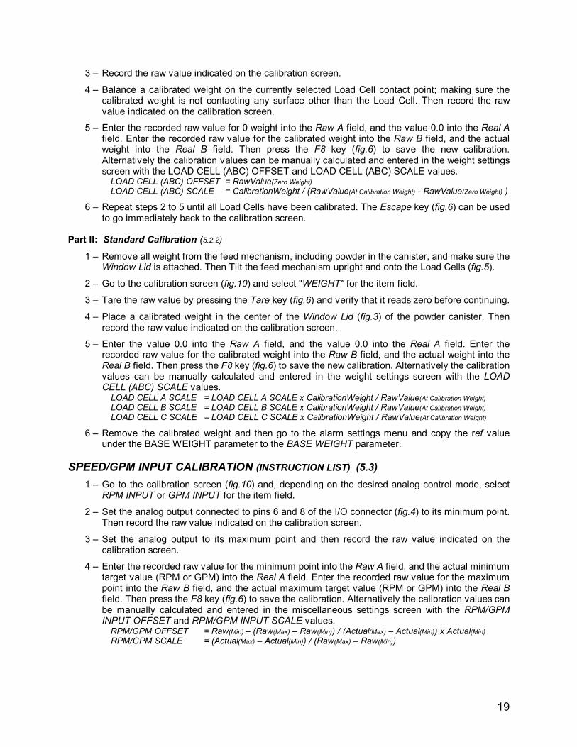
3 – Record the raw value indicated on the calibration screen.
4 – Balance a calibrated weight on the currently selected Load Cell contact point; making sure the calibrated weight is not contacting any surface other than the Load Cell. Then record the raw value indicated on the calibration screen.
5 – Enter the recorded raw value for 0 weight into the Raw A field, and the value 0.0 into the Real A field. Enter the recorded raw value for the calibrated weight into the Raw B field, and the actual weight into the Real B field. Then press the F8 key (fig.6) to save the new calibration. Alternatively the calibration values can be manually calculated and entered in the weight settings screen with the LOAD CELL (ABC) OFFSET and LOAD CELL (ABC) SCALE values.
LOAD CELL (ABC) OFFSET = RawValue(Zero Weight) LOAD CELL (ABC) SCALE = CalibrationWeight / (RawValue(At Calibration Weight) - RawValue(Zero Weight) )
6 – Repeat steps 2 to 5 until all Load Cells have been calibrated. The Escape key (fig.6) can be used to go immediately back to the calibration screen.
Part II: Standard Calibration (5.2.2)
1 – Remove all weight from the feed mechanism, including powder in the canister, and make sure the Window Lid is attached. Then Tilt the feed mechanism upright and onto the Load Cells (fig.5).
2 – Go to the calibration screen (fig.10) and select "WEIGHT" for the item field.
3 – Tare the raw value by pressing the Tare key (fig.6) and verify that it reads zero before continuing.
4 – Place a calibrated weight in the center of the Window Lid (fig.3) of the powder canister. Then record the raw value indicated on the calibration screen.
5 – Enter the value 0.0 into the Raw A field, and the value 0.0 into the Real A field. Enter the recorded raw value for the calibrated weight into the Raw B field, and the actual weight into the Real B field. Then press the F8 key (fig.6) to save the new calibration. Alternatively the calibration values can be manually calculated and entered in the weight settings screen with the LOAD CELL (ABC) SCALE values.
LOAD CELL A SCALE = LOAD CELL A SCALE x CalibrationWeight / RawValue(At Calibration Weight)
LOAD CELL B SCALE = LOAD CELL B SCALE x CalibrationWeight / RawValue(At Calibration Weight)
LOAD CELL C SCALE = LOAD CELL C SCALE x CalibrationWeight / RawValue(At Calibration Weight)
6 – Remove the calibrated weight and then go to the alarm settings menu and copy the ref value under the BASE WEIGHT parameter to the BASE WEIGHT parameter.
SPEED/GPM INPUT CALIBRATION (INSTRUCTION LIST) (5.3)
1 – Go to the calibration screen (fig.10) and, depending on the desired analog control mode, select RPM INPUT or GPM INPUT for the item field.
2 – Set the analog output connected to pins 6 and 8 of the I/O connector (fig.4) to its minimum point. Then record the raw value indicated on the calibration screen.
3 – Set the analog output to its maximum point and then record the raw value indicated on the calibration screen.
4 – Enter the recorded raw value for the minimum point into the Raw A field, and the actual minimum target value (RPM or GPM) into the Real A field. Enter the recorded raw value for the maximum point into the Raw B field, and the actual maximum target value (RPM or GPM) into the Real B field. Then press the F8 key (fig.6) to save the calibration. Alternatively the calibration values can be manually calculated and entered in the miscellaneous settings screen with the RPM/GPM INPUT OFFSET and RPM/GPM INPUT SCALE values.
RPM/GPM OFFSET = Raw(Min) – (Raw(Max) – Raw(Min)) / (Actual(Max) – Actual(Min)) x Actual(Min) RPM/GPM SCALE = (Actual(Max) – Actual(Min)) / (Raw(Max) – Raw(Min))

20
21
2-21-2020 Brig’s Machining Company
MODEL 171D POWDER FEEDER - OPERATORS MANUAL