Embed Size (px)
Citation preview
Product Data Sheet PS-00717, Rev. D April 2013
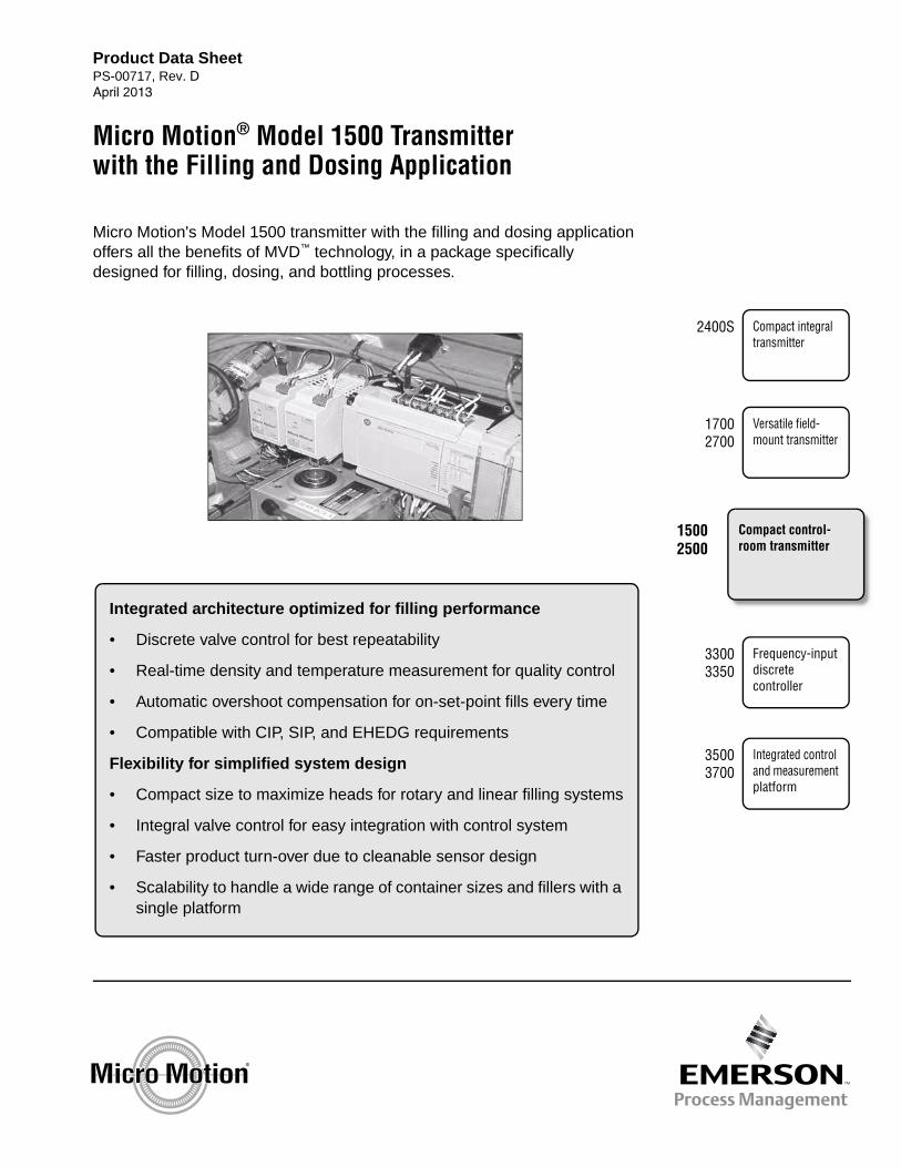
Micro Motion's Model 1500 transmitter with the filling and dosing application offers all the benefits of MVD™ technology, in a package specifically designed for filling, dosing, and bottling processes.
Integrated architecture optimized for filling performance
• Discrete valve control for best repeatability
• Real-time density and temperature measurement for quality control
• Automatic overshoot compensation for on-set-point fills every time
• Compatible with CIP, SIP, and EHEDG requirements
Flexibility for simplified system design
• Compact size to maximize heads for rotary and linear filling systems
• Integral valve control for easy integration with control system
• Faster product turn-over due to cleanable sensor design
• Scalability to handle a wide range of container sizes and fillers with asingle platform
Micro Motion® Model 1500 Transmitter with the Filling and Dosing Application
Frequency-input discrete controller
Integrated control and measurement platform
33003350
2400S
35003700
Compact integral transmitter
15002500
Compact control-room transmitter
17002700
Versatile field-mount transmitter
2 Model 1500 Transmitter with the Filling and Dosing Application
Micro Motion Model 1500 transmitter with the filling and dosing application
Micro Motion's Model 1500 transmitter with the filling and dosing application combines the benefits of Micro Motion MVD™ technology, a software package specially designed for filling, dosing, and bottling processes, and compatibility with a wide range of sensors, including hygienic models for CIP, SIP, and EHEDG certification.
Filling and dosing application. Micro Motion’s new patented filling and dosing application is packed with features for precise control and delivery of small quantities of fluids over broad ranges of process conditions.
• Measure by mass or volume, with sensor accuracies up to 0.05%, independent of changes in temperature, density, or viscosity.
• Measure a wide range of both liquids and gases, including liquids with entrained air and suspended solids. We have experience with high-viscosity pastes, creams, emulsions, and slurries.
• Instantly validate product quality using the secondary density or temperature measurement, eliminating the need for expensive lab checks.
• Special update rate between transmitter and sensor enables near-instantaneous response
• Overshoot compensation (OC) automatically adjusts the valve closure signal to accommodate changing process conditions
• User-selectable OC algorithms: never overfill, never underfill, fixed, rolling average
• Select from a variety of standard measurement units, or define your own
• Set up one-stage or two-stage filling, using standard discrete (ON/OFF) valves, or configure the transmitter to control a three-position analog valve
• Automatic or manual purge cycle
• Sensors suitable for both CIP and SIP cleaning, enabling rapid product changeover
Contents
Model 1500 platform . . . . . . . . . . . . . . . . . . . . . . . 3Application architecture and process. . . . . . . . . . . 4Accuracy, reliability, and repeatability . . . . . . . . . . 5User interface . . . . . . . . . . . . . . . . . . . . . . . . . . . . 6Electrical connections . . . . . . . . . . . . . . . . . . . . . . 7Input/output signals . . . . . . . . . . . . . . . . . . . . . . . . 7Digital communications . . . . . . . . . . . . . . . . . . . . . 8Power supply . . . . . . . . . . . . . . . . . . . . . . . . . . . . . 8
Environmental limits . . . . . . . . . . . . . . . . . . . . . . . 8Environmental effects . . . . . . . . . . . . . . . . . . . . . . 8Hazardous area classifications . . . . . . . . . . . . . . . 9Physical specifications . . . . . . . . . . . . . . . . . . . . . 9Transmitter dimensions . . . . . . . . . . . . . . . . . . . . 10Remote core processor dimensions . . . . . . . . . . 11Ordering information . . . . . . . . . . . . . . . . . . . . . . 12
Model 1500 Transmitter with the Filling and Dosing Application 3
Model 1500 platform
Micro Motion’s popular Model 1500 transmitter provides the platform for the filling and dosing application.
The Model 1500 delivers a big transmitter in a small package. Designed for DIN rail mounting, it measures a tiny 4” × 4.5” × 1.8” — perfect for carousels or skids.
Embedded MVD technology provides front-end digital processing, for dramatically reduced signal noise, faster response time, and expanded diagnostics.
The Model 1500 connects to a wide range of Micro Motion sensors, using standard 4-wire cable for significantly reduced installation costs. And because the sensor is powered by the transmitter, there’s no need to run separate power to the sensor.
Three input/output channels can be configured for mA output, discrete output, discrete input, or three-position analog valve control.
A status LED on the transmitter face indicates transmitter health at a glance.
Meter verification. Meter verification is an application available in conjunction with Micro Motion ELITE® meters utilizing the enhanced core processor. Initiated by a user command, the method measures mechanical characteristics of the meter to a very high accuracy. When a change in the structural stiffness of the sensor tubes is detected, the device indicates the meter may no longer meet factory specifications. The structural integrity test verifies complete meter performance from tube structure to electronics to signal processing for complete performance certainty.
4 Model 1500 Transmitter with the Filling and Dosing Application
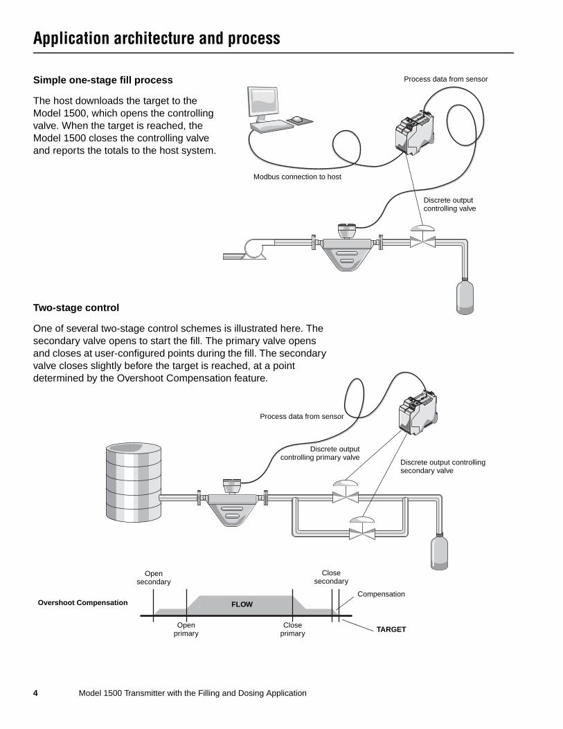
Application architecture and process
Discrete outputcontrolling primary valve
Discrete output controlling secondary valve
Process data from sensor
Open secondary
Close primary
Compensation
TARGET
Close secondary
FLOW
Open primary
Overshoot Compensation
Modbus connection to host
Discrete output controlling valve
Process data from sensorSimple one-stage fill process
The host downloads the target to the Model 1500, which opens the controlling valve. When the target is reached, the Model 1500 closes the controlling valve and reports the totals to the host system.
Two-stage control
One of several two-stage control schemes is illustrated here. The secondary valve opens to start the fill. The primary valve opens and closes at user-configured points during the fill. The secondary valve closes slightly before the target is reached, at a point determined by the Overshoot Compensation feature.
Model 1500 Transmitter with the Filling and Dosing Application 5
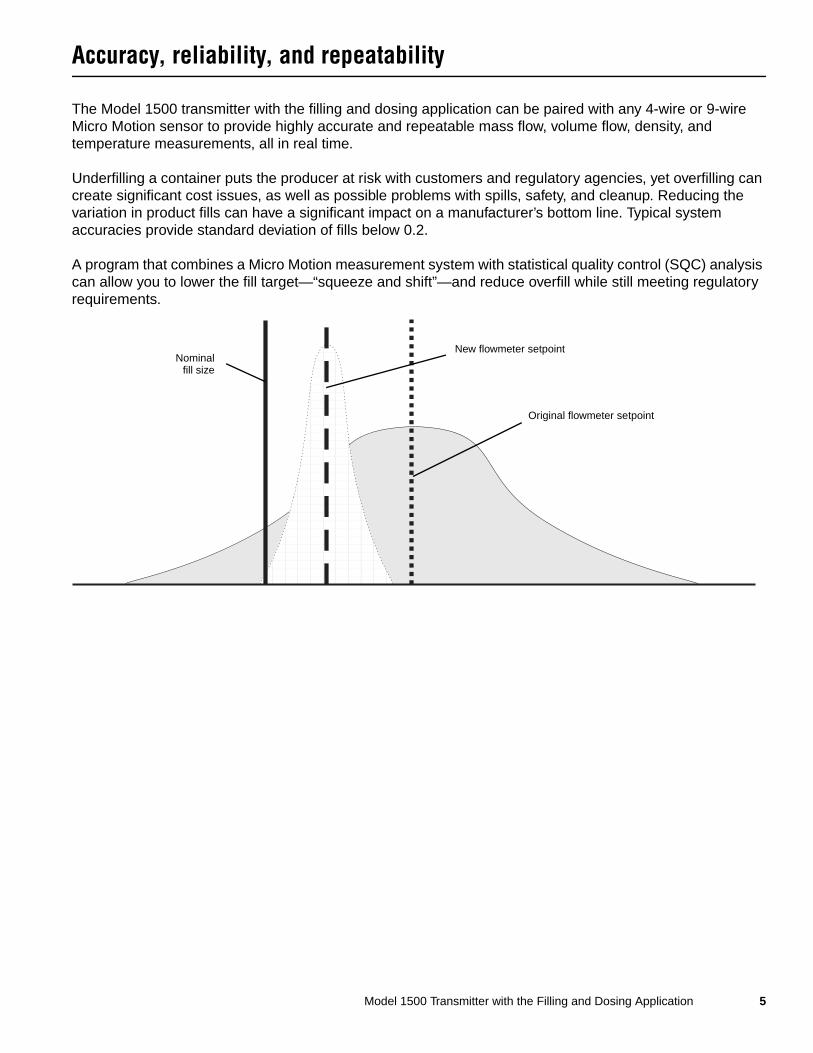
Accuracy, reliability, and repeatability
The Model 1500 transmitter with the filling and dosing application can be paired with any 4-wire or 9-wire Micro Motion sensor to provide highly accurate and repeatable mass flow, volume flow, density, and temperature measurements, all in real time.
Underfilling a container puts the producer at risk with customers and regulatory agencies, yet overfilling can create significant cost issues, as well as possible problems with spills, safety, and cleanup. Reducing the variation in product fills can have a significant impact on a manufacturer’s bottom line. Typical system accuracies provide standard deviation of fills below 0.2.
A program that combines a Micro Motion measurement system with statistical quality control (SQC) analysis can allow you to lower the fill target—“squeeze and shift”—and reduce overfill while still meeting regulatory requirements.
aaaaaaaaaaaaaaaaaaaaaaaaaaaaaaaaaaaaaaaaaaaaaaaaaaaaaaaaaaaaaaaaaaaaaaaaaaaaaaaaaaaaaaaaaaaaaaaaaaaaaaaaaaaaaaaaaaaaaaaaaaaaaaaaaaaaaaaaaaaaaaaaaaaaaaaaaaaaaaaaaaaaaaaaaaaaaaaaaaaaaaaaaaaaaaaaaaaaaaaaaaaaaaaaaaaaaaaaaaaaaaaaaaaaaaaaaaaaaaaaaaaaaaaaaaaaaaaaaaaaaaaaaaaaaaaaaaaaaaaaaaaaaaaaaaaaaaaaaaaaaaaaaaaaaaaaaaaaaaaaaaaaaaaaaaaaaaaaaaaaa
Nominalfill size
Original flowmeter setpoint
New flowmeter setpoint
6 Model 1500 Transmitter with the Filling and Dosing Application
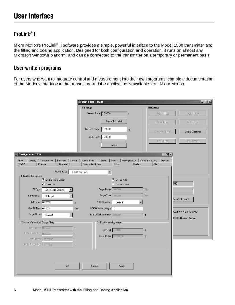
User interface
ProLink® II
Micro Motion’s ProLink® II software provides a simple, powerful interface to the Model 1500 transmitter and the filling and dosing application. Designed for both configuration and operation, it runs on almost any Microsoft Windows platform, and can be connected to the transmitter on a temporary or permanent basis.
User-written programs
For users who want to integrate control and measurement into their own programs, complete documentation of the Modbus interface to the transmitter and the application is available from Micro Motion.
Model 1500 Transmitter with the Filling and Dosing Application 7
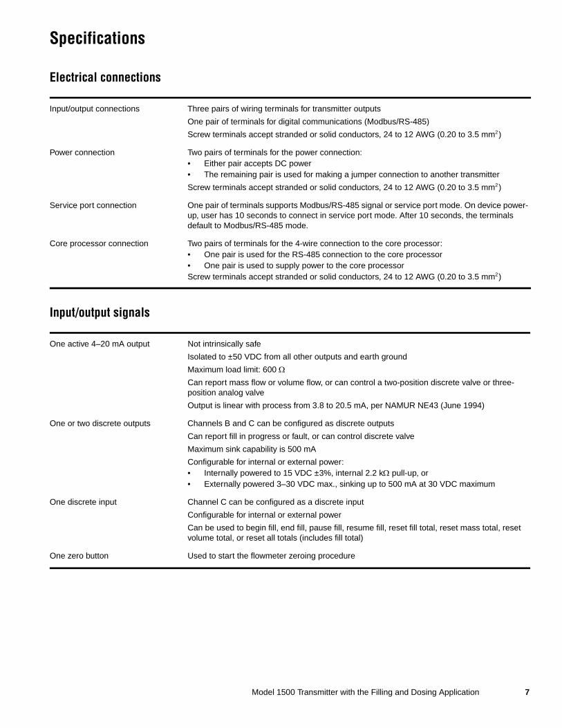
Specifications
Electrical connections
Input/output signals
Input/output connections Three pairs of wiring terminals for transmitter outputs
One pair of terminals for digital communications (Modbus/RS-485)
Screw terminals accept stranded or solid conductors, 24 to 12 AWG (0.20 to 3.5 mm2)
Power connection Two pairs of terminals for the power connection:• Either pair accepts DC power• The remaining pair is used for making a jumper connection to another transmitter
Screw terminals accept stranded or solid conductors, 24 to 12 AWG (0.20 to 3.5 mm2)
Service port connection One pair of terminals supports Modbus/RS-485 signal or service port mode. On device power-up, user has 10 seconds to connect in service port mode. After 10 seconds, the terminals default to Modbus/RS-485 mode.
Core processor connection Two pairs of terminals for the 4-wire connection to the core processor:• One pair is used for the RS-485 connection to the core processor• One pair is used to supply power to the core processorScrew terminals accept stranded or solid conductors, 24 to 12 AWG (0.20 to 3.5 mm2)
One active 4–20 mA output Not intrinsically safe
Isolated to ±50 VDC from all other outputs and earth ground
Maximum load limit: 600 Ω
Can report mass flow or volume flow, or can control a two-position discrete valve or three-position analog valve
Output is linear with process from 3.8 to 20.5 mA, per NAMUR NE43 (June 1994)
One or two discrete outputs Channels B and C can be configured as discrete outputs
Can report fill in progress or fault, or can control discrete valve
Maximum sink capability is 500 mA
Configurable for internal or external power:• Internally powered to 15 VDC ±3%, internal 2.2 kΩ pull-up, or• Externally powered 3–30 VDC max., sinking up to 500 mA at 30 VDC maximum
One discrete input Channel C can be configured as a discrete input
Configurable for internal or external power
Can be used to begin fill, end fill, pause fill, resume fill, reset fill total, reset mass total, reset volume total, or reset all totals (includes fill total)
One zero button Used to start the flowmeter zeroing procedure
8 Model 1500 Transmitter with the Filling and Dosing Application
Specifications continued
Digital communications
Power supply
Environmental limits
Environmental effects
Service port After device power up, terminals 33 and 34 are available in service port mode for 10 seconds:• Modbus RTU protocol• 38,400 baud• No parity• One stop bit• Address = 111
Modbus/RS-485 After 10 seconds, terminals 33 and 34 default to Modbus/RS-485:• Modbus RTU or Modbus ASCII protocol (default: Modbus RTU)• 1200 to 38,400 baud rate (default: 9600)• Stop bit configurable (default: one stop bit)• Parity configurable (default: odd parity)
Requires DC power
Meets Installation (Overvoltage) Category II, Pollution Degree 2 requirements
Power requirements 19.2 to 28.8 VDC, 6.3 watts maximum
At startup, transmitter power source must provide a minimum of 1.0 amperes of short-term current per transmitter
Length and conductor diameter of the power cable must be sized to provide 19.2 VDC minimum at the power terminals, at a load current of 330 mA
Fuse IEC 1.6A slowblow fuse
Ambient temperature limits • Operating: –40 to +131 °F (–40 to +55 °C)• Storage: –40 to +185 °F (–40 to +85 °C)
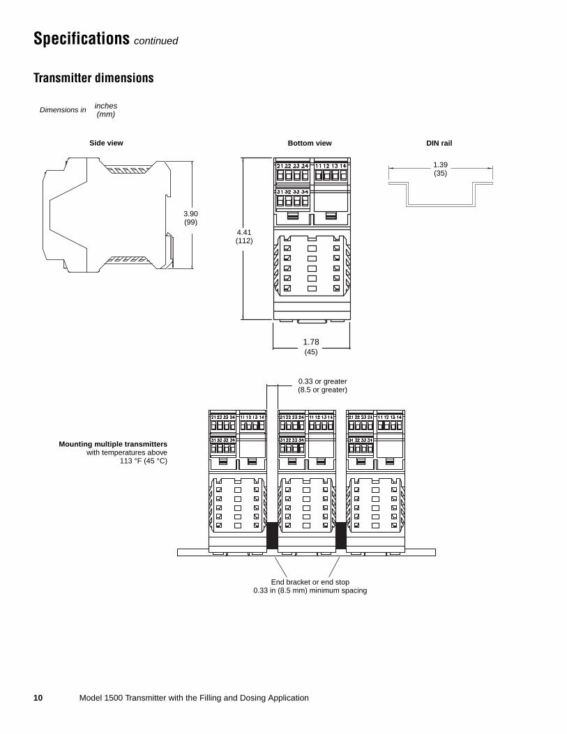
If temperature is above 113 °F (45 °C) and you are mounting multiple transmitters, they must be mounted at least 8.5 mm apart.
Humidity limits 5 to 95% relative humidity, non-condensing at 140 °F (60 °C)
Vibration limits Meets IEC68.2.6, endurance sweep, 5 to 2000 Hz, 50 sweep cycles at 1.0 g
EMI effects Meets EMC directive 89/336/EEC per EN 61326 IndustrialComplies with NAMUR NE21 (May 1999)
Ambient temperature effect On analog output ±0.005% of span per °C
Model 1500 Transmitter with the Filling and Dosing Application 9
Specifications continued
Hazardous area classifications
Physical specifications
CSA(1) C-US
(1) CSA is a Canadian approvals agency that provides approvals accepted both in Canada and in the U.S.A. (C-US).
Transmitter Class I, Div. 2, Groups A, B, C, and D
Sensor and sensor wiring to transmitter
Class I, Div. 1, Groups C and D or Class II, Div. 1, Groups E, F, and G
ATEX(2)
(2) ATEX is a European directive.
CE 0575 ATEX II(2) G [EEx ib] IIB/IICFor ATEX compliance, ambient temperature is limited to –40 to +131 °F (–40 to +55 °C)
Housing Polyamide PA 6.6
Weight 0.52 lbs (0.24 kg)
Dimensions See following figures for dimensions of the Model 1500 transmitter and the remote core processor.
For sensor dimensions, refer to sensor specifications.
Status LED Three-color LED status light on face of transmitter indicates flowmeter condition at a glance, using a solid green, yellow or red light. Zero in progress is indicated by a flashing yellow light.
Zero button A zero button on the face of the transmitter can be used to start the transmitter zero process.
Mounting and cabling DIN rail transmitters are mounted on a 35 mm rail which requires an independent ground. They may be used with any Micro Motion 4-wire or 9-wire sensor. For a 4-wire connection, use standard 4-wire twisted-pair shielded signal cable, up to 1000 feet (300 meters) in length, between the sensor and the transmitter. For 9-wire sensors, the remote core processor must be mounted within 60 feet (20 meters) of the sensor, using 9-wire Micro Motion signal cable. The transmitter can then be mounted up to 1000 feet (300 meters) from the remote core processor.
Maximum cable lengths between sensor and transmitter
Cable type Wire gauge Maximum length
Micro Motion 9-wire Not applicable 60 feet (20 meters)(1)
(1) This is the maximum distance between a remote core processor and the sensor. An additional run of 4-wire cable is needed between the remote core processor and the transmitter.
Micro Motion 4-wire Not applicable 1000 feet (300 meters)
User-supplied 4-wire(2)
(2) Micro Motion recommends using Micro Motion cable.
• Power wires (VDC) 22 AWG (0.35 mm2) 300 feet (90 meters)
20 AWG (0.5 mm2) 500 feet (150 meters)
18 AWG (0.8 mm2) 1000 feet (300 meters)
• Signal wires (RS-485) 22 AWG (0.35 mm2) or larger 1000 feet (300 meters)
10 Model 1500 Transmitter with the Filling and Dosing Application
Specifications continued
Transmitter dimensions
4.41(112)
Bottom view
1.78(45)
1.39(35)
DIN rail
Dimensions in inches(mm)
Side view
3.90(99)
0.33 or greater(8.5 or greater)
End bracket or end stop0.33 in (8.5 mm) minimum spacing
Mounting multiple transmitterswith temperatures above
113 °F (45 °C)
Model 1500 Transmitter with the Filling and Dosing Application 11
Specifications continued
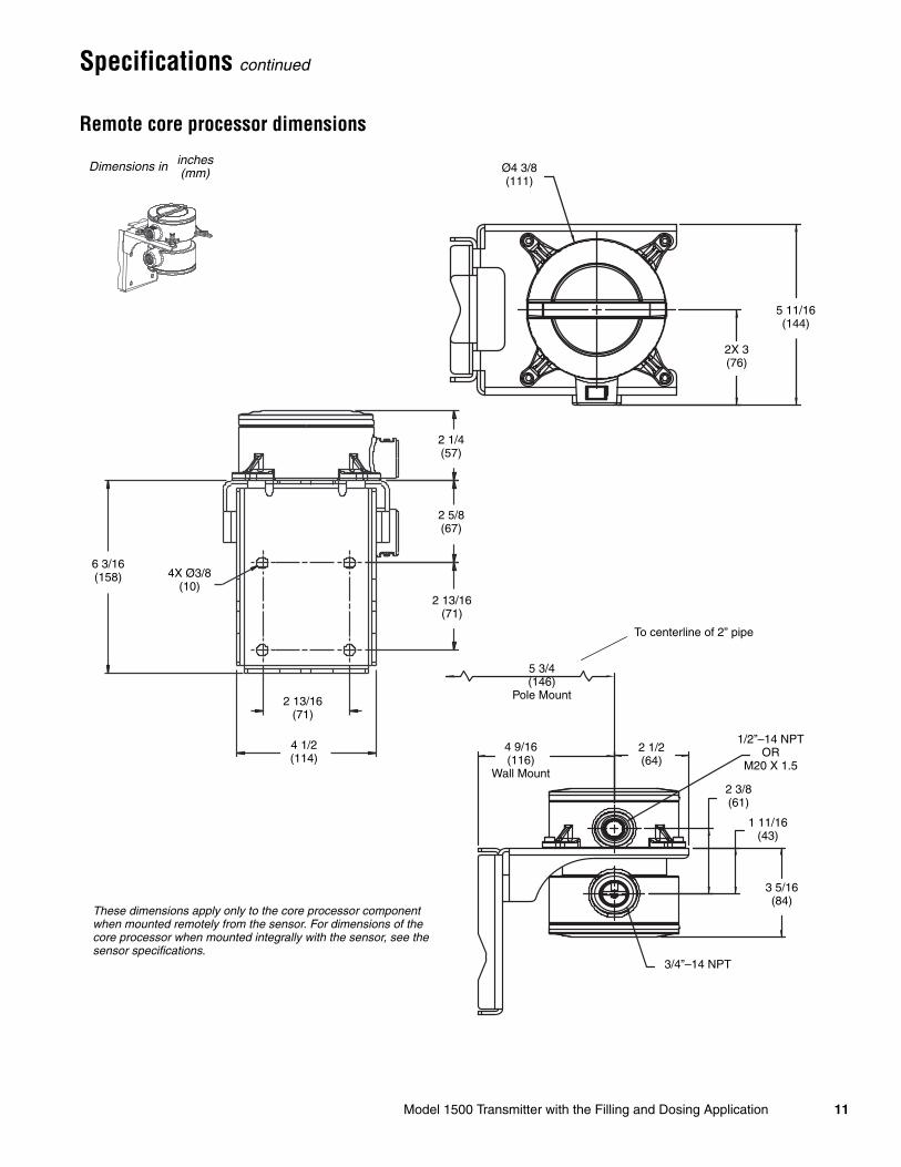
Remote core processor dimensions
Ø4 3/8(111)
2 13/16(71)
2 1/4(57)
4 1/2(114)
6 3/16(158)
2X 3(76)
2 5/8(67)
4X Ø3/8(10)
2 13/16(71)
5 11/16(144)
1/2”–14 NPTOR
M20 X 1.5
3 5/16(84)
1 11/16(43)
To centerline of 2” pipe
5 3/4(146)
Pole Mount
2 1/2(64)
4 9/16(116)
Wall Mount
3/4”–14 NPT
2 3/8(61)
These dimensions apply only to the core processor component when mounted remotely from the sensor. For dimensions of the core processor when mounted integrally with the sensor, see the sensor specifications.
Dimensions in inches(mm)

12 Model 1500 Transmitter with the Filling and Dosing Application
Ordering information
Model Product description
1500 Micro Motion Coriolis MVD 1500 single variable flow transmitter
Code Mounting
D 4-wire remote 35 mm DIN rail transmitter
B 4-wire remote 35 mm DIN rail transmitter with 9-wire remote core processor (includes 10 ft [3 m] CFEPS cable)
Code Power
3 19.2 to 28.8 VDC
Code Conduit connections
A None (for use with mounting option code D)
B(1)
(1) Available with mounting code B only.
1/2-inch NPT remote core processor — no gland
E(1) M20 remote core processor — no gland
F(1) Remote core processor — brass/nickel cable gland
G(1) Remote core processor — stainless steel cable gland
Code Output options
C One mA, two DO; RS-485
Code Terminals
B Screw terminals
Code Approvals
M Micro Motion standard (no approval)
C CSA (Canada only)
A CSA C-US (U.S.A. and Canada)
B ATEX — safe area with intrinsically safe sensor outputs
P(2)
(2) Available only with language code M (Chinese).
NEPSI — safe area
Continued on next page
Model 1500 Transmitter with the Filling and Dosing Application 13
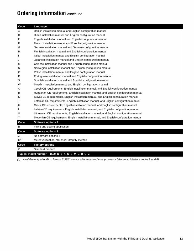
Ordering information continued
Code Language
A Danish installation manual and English configuration manual
D Dutch installation manual and English configuration manual
E English installation manual and English configuration manual
F French installation manual and French configuration manual
G German installation manual and German configuration manual
H Finnish installation manual and English configuration manual
I Italian installation manual and English configuration manual
J Japanese installation manual and English configuration manual
M Chinese installation manual and English configuration manual
N Norwegian installation manual and English configuration manual
O Polish installation manual and English configuration manual
P Portuguese installation manual and English configuration manual
S Spanish installation manual and Spanish configuration manual
W Swedish installation manual and English configuration manual
C Czech CE requirements, English installation manual, and English configuration manual
B Hungarian CE requirements, English installation manual, and English configuration manual
K Slovak CE requirements, English installation manual, and English configuration manual
T Estonian CE requirements, English installation manual, and English configuration manual
U Greek CE requirements, English installation manual, and English configuration manual
L Latvian CE requirements, English installation manual, and English configuration manual
V Lithuanian CE requirements, English installation manual, and English configuration manual
Y Slovenian CE requirements, English installation manual, and English configuration manual
Code Software options 1
B Filling and dosing application
Code Software options 2
Z No software options 2
C(1)
(1) Available only with Micro Motion ELITE® sensor with enhanced core processor (electronic interface codes 2 and 4).
Meter verification, structural integrity method
Code Factory options
Z Standard product
Typical model number: 1500 D 3 A C B M E B C Z

14 Model 1500 Transmitter with the Filling and Dosing Application

Model 1500 Transmitter with the Filling and Dosing Application 15
Emerson Process ManagementMicro Motion AmericasWorldwide Headquarters7070 Winchester CircleBoulder, Colorado USA 80301T: 800 522 6277T: +1 (303) 527 5200F: +1 (303) 530 8459Mexico T: 52 55 5366 2622Argentina T: 54 11 4837 7000Brazil T: 55 15 3238 3677Venezuela T: 58 26 1731 3394
Emerson Process ManagementMicro Motion Europe/Middle EastCentral & Eastern Europe T: +41 41 7686 111Dubai T: 971-4 8835235France T: 0800 917 901Germany T: 0800 182 5347Italy T: 8008 77334The Netherlands T: (31) 318 495 555U.K. T: 0870 240 1978Russia/CIS T: +7 495 981 9811
Emerson Process ManagementMicro Motion Asia Pacific
T: (61) 3 9721 0200T: (86) 21 2892 9000T: (91) 22 5662 0566T: (81) 3 5769 6803T: (82) 2 3438 4600
Australia China India Japan South K o r e a Singapore T: (65) 6 777 8211
Micro Motion—The undisputed leader in flow and density measurement
WWW.micromotion.com
World-leading Micro Motion measurement solutions from Emerson Process Management deliver what you need most:
Technology leadershipMicro Motion introduced the first reliable Coriolis meter in 1977. Since that time, our ongoing product development has enabled us to provide the highest performing measurement devices available.
Product breadthFrom compact, drainable process control to high flow rate fiscal transfer—look no further than Micro Motion for the widest range of measurement solutions.
Unparalleled valueBenefit from expert phone, field, and application service and support made possible by more than 750,000 meters installed worldwide and 30 years of flow and density measurement experience.
© 2013 Micro Motion, Inc. All rights reserved. Micro Motion is committed to continuous product improvement. As a result, all specifications are subject to change without notice. ELITE and ProLink are registered trademarks, and MVD and MVD Direct Connect are trademarks of Micro Motion, Inc., Boulder, Colorado. Micro Motion is a registered trade name of Micro Motion, Inc., Boulder, Colorado. The Micro Motion and Emerson logos are trademarks and service marks of Emerson Electric Co. All other trademarks are property of their respective owners.