Embed Size (px)
Citation preview

MODBUS RTU / MODBUS TCPfor MODULYS GP – Modular UPS of the Green Power 2.0 range -
and ITYS PRO UPS ranges
Installations- und Bedienungsanleitung DE
Installation and operating manual EN
Manual de instalación y funcionamiento ES
Manuel d'installation et d'utilisation FR
Manuale di installazione e uso IT

2 MODBUS RTU / MODBUS TCP - Ref.: IOMMASOPXX04-EN 00
Thank you for choosing a SOCOMEC product.
This equipment is fitted with up-to-date technology. The rectifier and inverter subsets are provided with power semiconductors
(IGBT), including a digital micro-controller.
Our equipment complies with standard IEC EN 62040-2.
CAUTION.
This is a product for restricted sales distribution to selected partners. Installation restrictions or additional measures
may be needed to prevent disturbances.
SOCOMEC reserves the right to modify their specifications at any time as far as this contributes to technical progress.
SAFETY REQUIREMENTS
Conditions of use
Read these operating instructions carefully before using the MODBUS interface.
Repairs must only be carried out by suitably qualified, authorised staff.
It is advisable to keep the UPS Green Power environment below manufacturer-specified values for optimum operation.
UPS Operating Reference Standard
Comply with safety requirements.
Read the UPS operating instructions carefully.
This equipment meets the requirements of the European directives applied to this product. As a result it is labelled as follows:
ENVIRONMENT
Recycling of electrical products and equipment
Provision is made in European countries to dismantle and recycle system materials. The various components must be disposed of
in accordance with legislation in force in the country where the system is installed.
SOCOMEC retains the full and exclusive ownership rights over this document. Only a personal right to use the document for the
application indicated by SOCOMEC is granted to the recipient of such document. The reproduction, modification and distribution of
this document, partially or in its entirety and in any way, is expressly prohibited except upon Socomec’s express prior written consent.
This document is not a specification. SOCOMEC reserves the right to make any changes to its content without prior notice.
FOREWORD

3MODBUS RTU / MODBUS TCP - Ref.: IOMMASOPXX04-EN 00
SUMMARY
EN
GL
ISH
1. GENERAL AIM . . . . . . . . . . . . . . . . . . . . . . . . . . . . . . . . . . . . . . . . . . . . . . . . . . . . . . . . . . . . 4
2. MODBUS RTU – RS485 INTERFACE (ADC+SL CARD) . . . . . . . . . . . . . . . . . . . . . . . . . . . . . 5
2.1. INSTALLATION OF THE RTU CARD . . . . . . . . . . . . . . . . . . . . . . . . . . . . . . . . . 5
3. MODBUS TCP – IDA INTERFACE (MODBUS TCP CARD) . . . . . . . . . . . . . . . . . . . . . . . . . . . 6
3.1. INSTALLATION OF THE MODBUS TCP CARD . . . . . . . . . . . . . . . . . . . . . . . . . 6
3.2. SERIAL CONNECTION DEFAULT SETTING . . . . . . . . . . . . . . . . . . . . . . . . . . . . 6
3.3. FEATURES AND LED DESCRIPTION . . . . . . . . . . . . . . . . . . . . . . . . . . . . . . . . 6
4. MODBUS UPS DATA ACCESS . . . . . . . . . . . . . . . . . . . . . . . . . . . . . . . . . . . . . . . . . . . . . . . . 7
4.1. MODBUS GENERIC TABLE . . . . . . . . . . . . . . . . . . . . . . . . . . . . . . . . . . . . . . . 7
5. MODBUS TABLE MODULYS GP . . . . . . . . . . . . . . . . . . . . . . . . . . . . . . . . . . . . . . . . . . . . . . 8
5.1. UPS ARCHITECTURE . . . . . . . . . . . . . . . . . . . . . . . . . . . . . . . . . . . . . . . . . . . . 8
5.2. MODULE ACCESS DATA TABLE MAPPING . . . . . . . . . . . . . . . . . . . . . . . . . . . 8
5.3. UPS CONFIGURATION TABLE, STARTING FROM 0X0001. . . . . . . . . . . . . . . . 9
5.4. UNIT CONFIGURATION TABLE, STARTING FROM 0X1000 . . . . . . . . . . . . . . 10
5.5. UPS REFERENCE TABLE, STARTING FROM 0X0010 . . . . . . . . . . . . . . . . . . 10
5.6. UPS STATUS TABLE, STARTING FROM 0X0030 . . . . . . . . . . . . . . . . . . . . . . 11
5.7. ADDITIONAL UPS STATUS TABLE, STARTING FROM 0X0034 . . . . . . . . . . . . 13
5.8. MODULE SUMMARY TABLE, STARTING FROM 0X0036 . . . . . . . . . . . . . . . . 14
5.9. UPS ALARMS TABLE, STARTING FROM 0X0038 . . . . . . . . . . . . . . . . . . . . . 15
5.10. ADDITIONAL ALARMS TABLE, STARTING FROM 0X003C . . . . . . . . . . . . . . . 17
5.11. MODULE ALARMS SYNTHESIS TABLE, STARTING FROM 0X103E . . . . . . . . 18
5.12. UPS MEASUREMENTS TABLE, STARTING FROM 0X0040 . . . . . . . . . . . . . . 19
5.13. COMMANDS TABLE, STARTING FROM 0X00C7 . . . . . . . . . . . . . . . . . . . . . . 21
5.14. UPS CLOCK TABLE, STARTING FROM 0X00CB . . . . . . . . . . . . . . . . . . . . . . 22
6. MODBUS TABLE ITYS PRO . . . . . . . . . . . . . . . . . . . . . . . . . . . . . . . . . . . . . . . . . . . . . . . . . 23
6.1. UPS CONFIGURATION TABLE, STARTING FROM 0X0001. . . . . . . . . . . . . . . 23
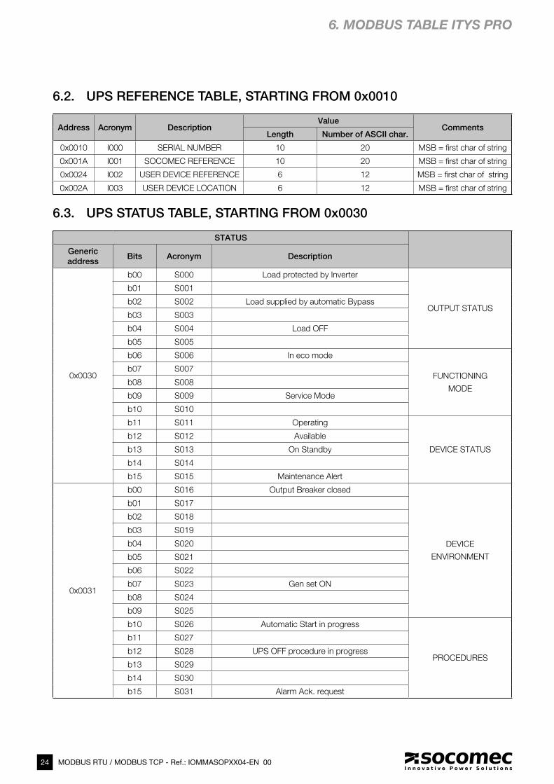
6.2. UPS REFERENCE TABLE, STARTING FROM 0X0010 . . . . . . . . . . . . . . . . . . 24
6.3. UPS STATUS TABLE, STARTING FROM 0X0030 . . . . . . . . . . . . . . . . . . . . . . 24
6.4. ADDITIONAL UPS STATUS TABLE, STARTING FROM 0X0034 . . . . . . . . . . . . 26
6.5. UPS ALARMS TABLE, STARTING FROM 0X0038 . . . . . . . . . . . . . . . . . . . . . 27
6.6. ADDITIONAL ALARMS TABLE, STARTING FROM 0X003C . . . . . . . . . . . . . . . 29
6.7. UPS MEASUREMENTS TABLE, STARTING FROM 0X0040 . . . . . . . . . . . . . . 30
6.8. COMMANDS TABLE, STARTING FROM 0X00C7 . . . . . . . . . . . . . . . . . . . . . . 32
6.9. UPS CLOCK TABLE, STARTING FROM 0X00CB . . . . . . . . . . . . . . . . . . . . . . 33
7. MODBUS PROTOCOL . . . . . . . . . . . . . . . . . . . . . . . . . . . . . . . . . . . . . . . . . . . . . . . . . . . . . 34
7.1. FUNCTIONS USED . . . . . . . . . . . . . . . . . . . . . . . . . . . . . . . . . . . . . . . . . . . . . 34
7.2. SUMMARY OF FRAME FORMAT . . . . . . . . . . . . . . . . . . . . . . . . . . . . . . . . . . 34
7.3. ERROR CODE MANAGEMENT . . . . . . . . . . . . . . . . . . . . . . . . . . . . . . . . . . . . 35
7.4. CRC CALCULATION . . . . . . . . . . . . . . . . . . . . . . . . . . . . . . . . . . . . . . . . . . . . 35
8. APPENDIX 1: INTERFACE CONFIGURATION USING DIGI® DEVICE DISCOVERY . . . . . . . . 36
9. APPENDIX 2: MODBUS TCP IDA SPECIFICATION . . . . . . . . . . . . . . . . . . . . . . . . . . . . . . . . 38

4 MODBUS RTU / MODBUS TCP - Ref.: IOMMASOPXX04-EN 00
1. GENERAL AIM
This document provides information on the MODBUS protocol serial link or Ethernet network for MODULYS GP – Modular UPS in
the Green Power 2.0 range - and ITYS PRO UPS ranges.
Before connecting monitoring equipment or a BMS system (building management system) to the UPS, it is necessary to install and
set up the serial interface or network configurations in the case of a network connection.

5MODBUS RTU / MODBUS TCP - Ref.: IOMMASOPXX04-EN 00
EN
GL
ISH
IN1- IN1+IN2+
IN2-
IN1- IN1+IN3+
IN3-C2 NO2
NO4C4
C1 NO1C3 NO3
NC1
2.1-1
2. MODBUS RTU – RS485 INTERFACE (ADC+SL CARD)
2.1. INSTALLATION OF THE RTU CARD
The interface must first be installed in the appropriate slot and
fastened to the com slots using 2 screws.
USING ADC+SL OPTION
This board includes RS485 insulated serial link and advanced
dry input and output contacts.
Installation
• Slot 1 or slot 2
• Screws for fixing
Cabling:
• RTX+ / RTX- connector
• Terminal resistor
MODBUS RTU serial setting via HMI:
• Slave number
• Baud rate (2400 / 9600 / 19200)
• Parity (none, even, odd)
• N bit (8)
• Stop bit set to 1 by default.
NOTE!
Refers to ADC+SL user's manual.
2.1-2 ITYS PRO communication slots 2.1-3 MODULYS GP communication slots
Slot 1
Slot 1
RS232(1) USB connector(1)Ethernet Ethernet network(1)
Slot 2
Slot 2
(1). Only for service.(1). MODBUS protocol is available through RS232, without the ADC+SL board.
ADC+SL board has to be used for RS485 serial link.

6 MODBUS RTU / MODBUS TCP - Ref.: IOMMASOPXX04-EN 00
3. MODBUS TCP – IDA INTERFACE (MODBUS TCP CARD)
3.1. INSTALLATION OF THE
MODBUS TCP CARD
The interface must first be installed in the appropriate slot and
fastened to the com slots using 2 screws.
3.2. SERIAL CONNECTION DEFAULT
SETTING
Serial connection parameters are set by an auto baud rate
procedure with a timeout of 40 seconds.
3.3. FEATURES AND LED DESCRIPTION
Standard supported:
IEEE 802.3
Mode supported:
10/100Base-T
10/100Mbps (auto sensing)
Half-duplex & Full-duplex mode (auto sensing)
Connector type:
RJ-45
LED type Color Meaning
RJ45
Yellow Line detected
Yellow flashing Searching line
Off No Ethernet line
RJ45
Green ON
Green flashing MODBUS TCP Traffic
Off No traffic
Interface LED TX ON Green When transmitting data
Interface LED RX ON Green When receiving data
5V ISO
NOTE!
Refers to Appendix 1.
3-1

7MODBUS RTU / MODBUS TCP - Ref.: IOMMASOPXX04-EN 00
EN
GL
ISH
4. MODBUS UPS DATA ACCESS
4.1. MODBUS GENERIC TABLE
Generic address Length (in 16 bits word) Table Description Type Access
0x0001 15 CONFIGURATIONS LIST OF CONFIG Values Read
0x0010 10 SERIAL NUMBER STRING ASCII Read
0x001A 10 SOCOMEC REF SOCOMEC RANGE NAME ASCII Read
0x0024 6 USER DEVICE REF CUSTOMER REF ASCII Read
0x002A 6 USER DEVICE LOCATION CUSTOMER LOCATION ASCII Read
0x0030 4+4 STATUS UPS STATUS Bits Read
0x0038 4+4 ALARMS UPS ALARMS Bits Read
0x0040 80 MEASUREMENTS LIST OF VALUES Values Read
0x00C0 7 MEASUR. CTRL MGNT BIT=1 = MEAS. MANAGED Bits Read
0x00C7 2 PERMISSONS BIT=1 CONTROL ENABLED Bits Read
0x00C9 2 CONTROLS 1 BIT = 1 CONTROL Bits Write
0x00CB 4 UPS CLOCK MSB/LSB FORMAT Values Read/write
Detail of data type:
Values: 1 word = 16 bit integer: value range: 0 to 65535 or -32768 to +32768
format of values is described in the measurements table.
ASCII: 1 word = 2 characters: MSB= 1st character ASCII code, LSB = 2nd character ASCII code
bits: 1 words = 16 binary info (Status or Alarms) bit=1 means info ON/YES, 0 = OFF/NO
Bit 0 = 1st data (S000 or A000, according to address)
8 MODBUS RTU / MODBUS TCP - Ref.: IOMMASOPXX04-EN 00
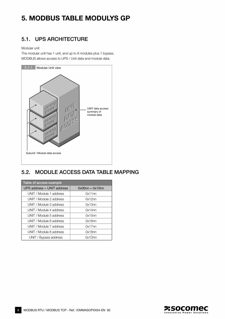
5. MODBUS TABLE MODULYS GP
5.1. UPS ARCHITECTURE
Modular unit
The modular unit has 1 unit, and up to 8 modules plus 1 bypass.
MODBUS allows access to UPS / Unit data and module data.
5.1-1 Modular Unit view
5.2. MODULE ACCESS DATA TABLE MAPPING
Table of access example
UPS address = UNIT address 0x00nn = 0x10nn
UNIT / Module 1 address 0x11nn
UNIT / Module 2 address 0x12nn
UNIT / Module 3 address 0x13nn
UNIT / Module 4 address 0x14nn
UNIT / Module 5 address 0x15nn
UNIT / Module 6 address 0x16nn
UNIT / Module 7 address 0x17nn
UNIT / Module 8 address 0x18nn
UNIT / Bypass address 0x1Dnn
Subunit / Module data access
UNIT data access:
summary of
module data
9MODBUS RTU / MODBUS TCP - Ref.: IOMMASOPXX04-EN 00
EN
GL
ISH
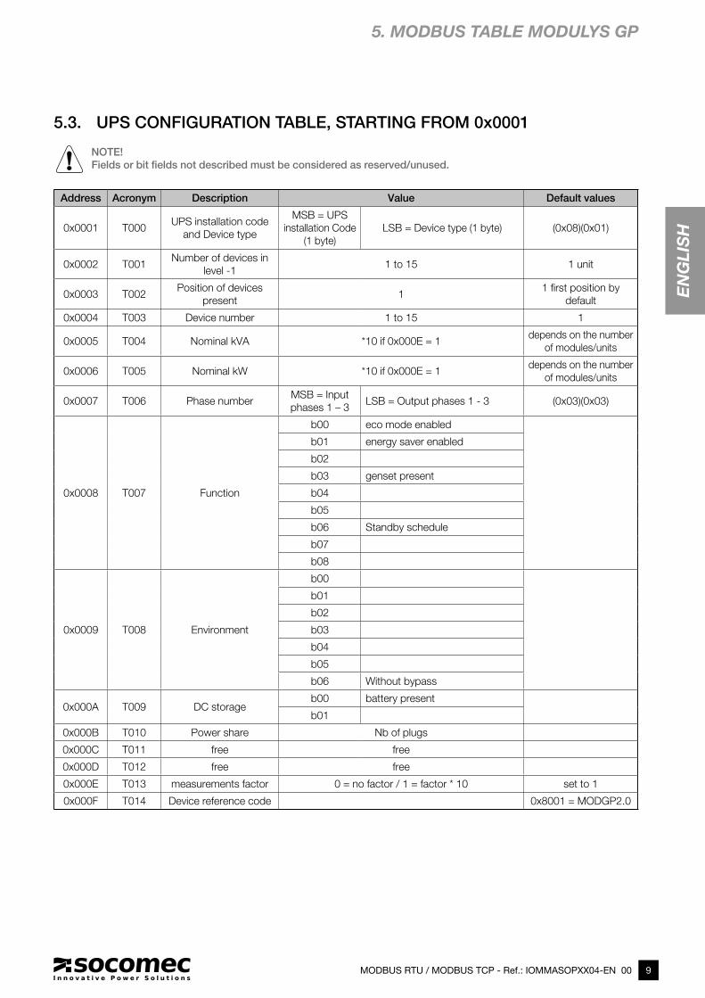
Address Acronym Description Value Default values
0x0001 T000UPS installation code
and Device type
MSB = UPS
installation Code
(1 byte)
LSB = Device type (1 byte) (0x08)(0x01)
0x0002 T001Number of devices in
level -11 to 15 1 unit
0x0003 T002Position of devices
present1
1 first position by
default
0x0004 T003 Device number 1 to 15 1
0x0005 T004 Nominal kVA *10 if 0x000E = 1depends on the number
of modules/units
0x0006 T005 Nominal kW *10 if 0x000E = 1depends on the number
of modules/units
0x0007 T006 Phase numberMSB = Input
phases 1 – 3 LSB = Output phases 1 - 3 (0x03)(0x03)
0x0008 T007 Function
b00 eco mode enabled
b01 energy saver enabled
b02
b03 genset present
b04
b05
b06 Standby schedule
b07
b08
0x0009 T008 Environment
b00
b01
b02
b03
b04
b05
b06 Without bypass
0x000A T009 DC storageb00 battery present
b01
0x000B T010 Power share Nb of plugs
0x000C T011 free free
0x000D T012 free free
0x000E T013 measurements factor 0 = no factor / 1 = factor * 10 set to 1
0x000F T014 Device reference code 0x8001 = MODGP2.0
5.3. UPS CONFIGURATION TABLE, STARTING FROM 0x0001
NOTE!
Fields or bit fields not described must be considered as reserved/unused.
5. MODBUS TABLE MODULYS GP
10 MODBUS RTU / MODBUS TCP - Ref.: IOMMASOPXX04-EN 00
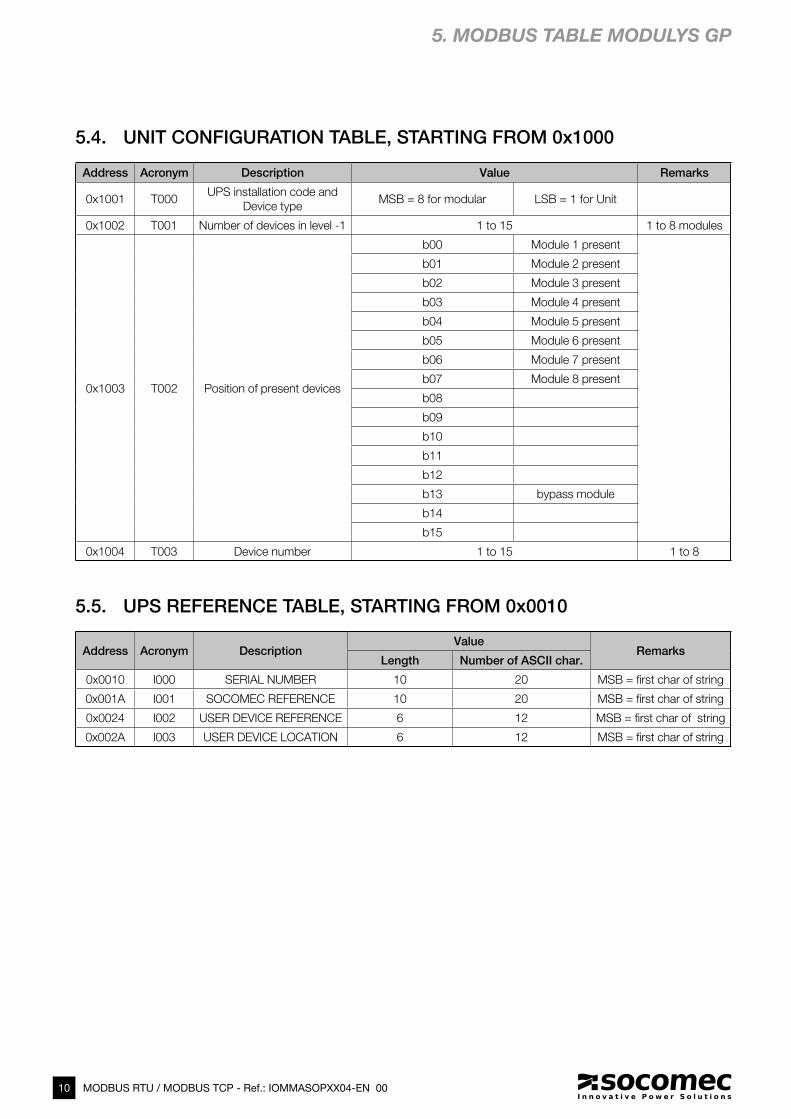
5.4. UNIT CONFIGURATION TABLE, STARTING FROM 0x1000
5. MODBUS TABLE MODULYS GP
Address Acronym Description Value Remarks
0x1001 T000UPS installation code and
Device typeMSB = 8 for modular LSB = 1 for Unit
0x1002 T001 Number of devices in level -1 1 to 15 1 to 8 modules
0x1003 T002 Position of present devices
b00 Module 1 present
b01 Module 2 present
b02 Module 3 present
b03 Module 4 present
b04 Module 5 present
b05 Module 6 present
b06 Module 7 present
b07 Module 8 present
b08
b09
b10
b11
b12
b13 bypass module
b14
b15
0x1004 T003 Device number 1 to 15 1 to 8
Address Acronym DescriptionValue
RemarksLength Number of ASCII char.
0x0010 I000 SERIAL NUMBER 10 20 MSB = first char of string
0x001A I001 SOCOMEC REFERENCE 10 20 MSB = first char of string
0x0024 I002 USER DEVICE REFERENCE 6 12 MSB = first char of string
0x002A I003 USER DEVICE LOCATION 6 12 MSB = first char of string
5.5. UPS REFERENCE TABLE, STARTING FROM 0x0010
11MODBUS RTU / MODBUS TCP - Ref.: IOMMASOPXX04-EN 00
EN
GL
ISH
5. MODBUS TABLE MODULYS GP
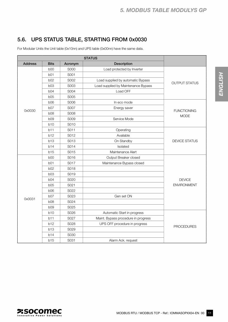
STATUS
Address Bits Acronym Description
0x0030
b00 S000 Load protected by Inverter
OUTPUT STATUS
b01 S001
b02 S002 Load supplied by automatic Bypass
b03 S003 Load supplied by Maintenance Bypass
b04 S004 Load OFF
b05 S005
b06 S006 In eco mode
FUNCTIONING
MODE
b07 S007 Energy saver
b08 S008
b09 S009 Service Mode
b10 S010
b11 S011 Operating
DEVICE STATUS
b12 S012 Available
b13 S013 On Standby
b14 S014 Isolated
b15 S015 Maintenance Alert
0x0031
b00 S016 Output Breaker closed
DEVICE
ENVIRONMENT
b01 S017 Maintenance Bypass closed
b02 S018
b03 S019
b04 S020
b05 S021
b06 S022
b07 S023 Gen set ON
b08 S024
b09 S025
b10 S026 Automatic Start in progress
PROCEDURES
b11 S027 Maint. Bypass procedure in progress
b12 S028 UPS OFF procedure in progress
b13 S029
b14 S030
b15 S031 Alarm Ack. request
5.6. UPS STATUS TABLE, STARTING FROM 0x0030
For Modular Units the Unit table (0x10nn) and UPS table (0x00nn) have the same data.
12 MODBUS RTU / MODBUS TCP - Ref.: IOMMASOPXX04-EN 00
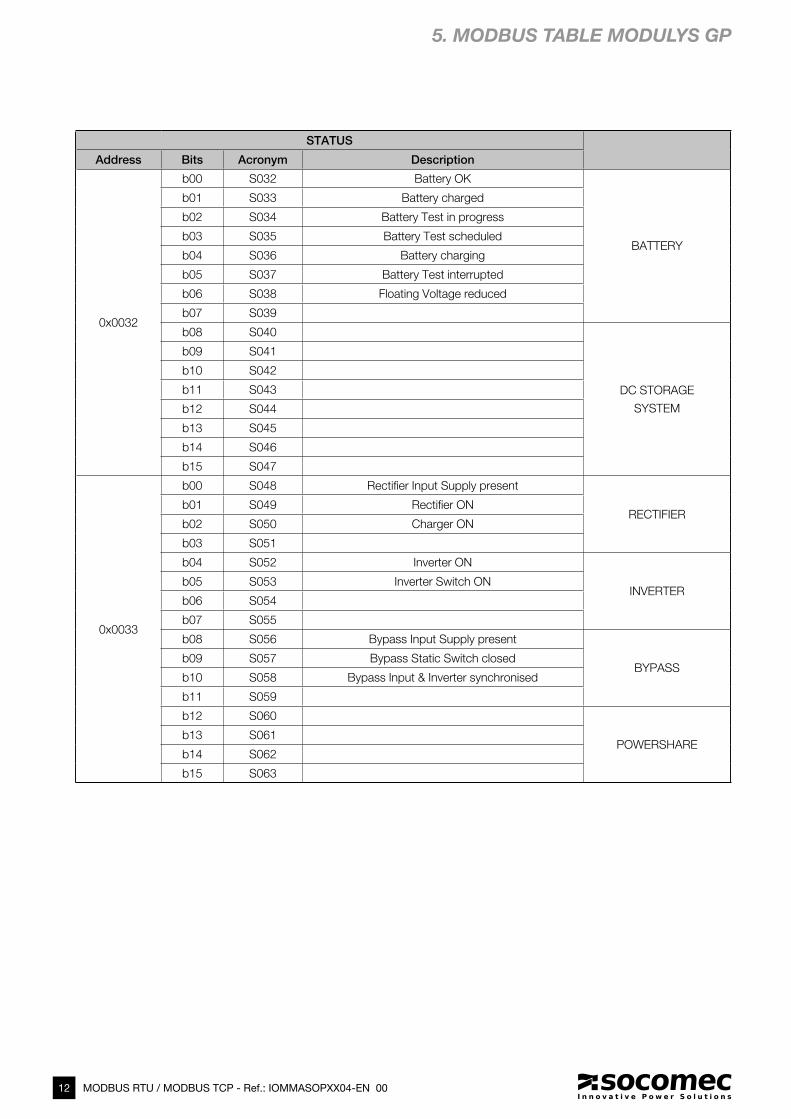
STATUS
Address Bits Acronym Description
0x0032
b00 S032 Battery OK
BATTERY
b01 S033 Battery charged
b02 S034 Battery Test in progress
b03 S035 Battery Test scheduled
b04 S036 Battery charging
b05 S037 Battery Test interrupted
b06 S038 Floating Voltage reduced
b07 S039
b08 S040
DC STORAGE
SYSTEM
b09 S041
b10 S042
b11 S043
b12 S044
b13 S045
b14 S046
b15 S047
0x0033
b00 S048 Rectifier Input Supply present
RECTIFIER b01 S049 Rectifier ON
b02 S050 Charger ON
b03 S051
b04 S052 Inverter ON
INVERTERb05 S053 Inverter Switch ON
b06 S054
b07 S055
b08 S056 Bypass Input Supply present
BYPASSb09 S057 Bypass Static Switch closed
b10 S058 Bypass Input & Inverter synchronised
b11 S059
b12 S060
POWERSHAREb13 S061
b14 S062
b15 S063
5. MODBUS TABLE MODULYS GP
13MODBUS RTU / MODBUS TCP - Ref.: IOMMASOPXX04-EN 00
EN
GL
ISH
STATUS
Generic
addressBits Acronym Description
0x0034
b00 S064 Board Slot 1 present
OPTIONS
b01 S065 Board Slot 2 present
b02 S066
b03 S067
b04 S068
b05 S069
b06 S070
b07 S071
b08 S072 Programmable S072
CUSTOM
IN / OUT
b09 S073 Programmable S073
b10 S074 Programmable S074
b11 S075 Programmable S075
b12 S076 Programmable S076
b13 S077 Programmable S077
b14 S078 Programmable S078
b15 S079 Programmable S079
0x0035
b00 S080 Programmable S080
CUSTOM
IN / OUT
b01 S081 Programmable S081
b02 S082 Programmable S082
b03 S083 Programmable S083
b04 S084 Programmable S084
b05 S085 Programmable S085
b06 S086 Programmable S086
b07 S087 Programmable S087
b08 S088 Programmable S088
b09 S089 Programmable S089
b10 S090 Programmable S090
b11 S091 Programmable S091
b12 S092 Programmable S092
b13 S093 Programmable S093
b14 S094 Programmable S094
b15 S095 Programmable S095
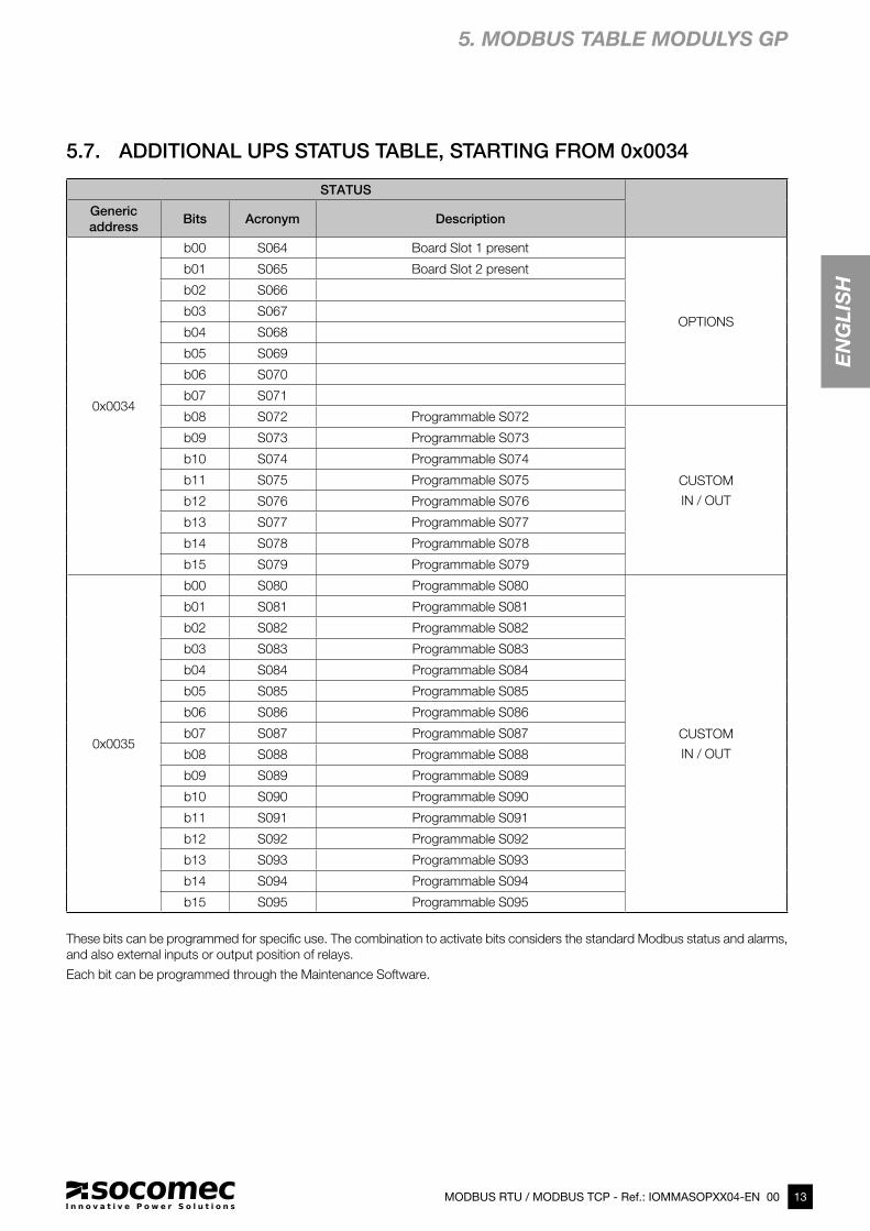
5.7. ADDITIONAL UPS STATUS TABLE, STARTING FROM 0x0034
These bits can be programmed for specific use. The combination to activate bits considers the standard Modbus status and alarms,
and also external inputs or output position of relays.
Each bit can be programmed through the Maintenance Software.
5. MODBUS TABLE MODULYS GP
14 MODBUS RTU / MODBUS TCP - Ref.: IOMMASOPXX04-EN 00
STATUS
Unit address Bits Acronym Description
0x1036
b00 S096 Module 1 Operating
MODULES
b01 S097 Module 2 Operating
b02 S098 Module 3 Operating
b03 S099 Module 4 Operating
b04 S100 Module 5 Operating
b05 S101 Module 6 Operating
b06 S102 Module 7 Operating
b07 S103 Module 8 Operating
b08 S104
b09 S105
b10 S106
b11 S107
b12 S108
b13 S109 Bypass Operating
b14 S110
b15 S111
0x1037
b00 S112 1 Available
MODULES
b01 S113 2 Available
b02 S114 3 Available
b03 S115 4 Available
b04 S116 5 Available
b05 S117 6 Available
b06 S118 7 Available
b07 S119 8 Available
b08 S120
b09 S121
b10 S122
b11 S123
b12 S124
b13 S125 Bypass Available
b14 S126
b15 S127
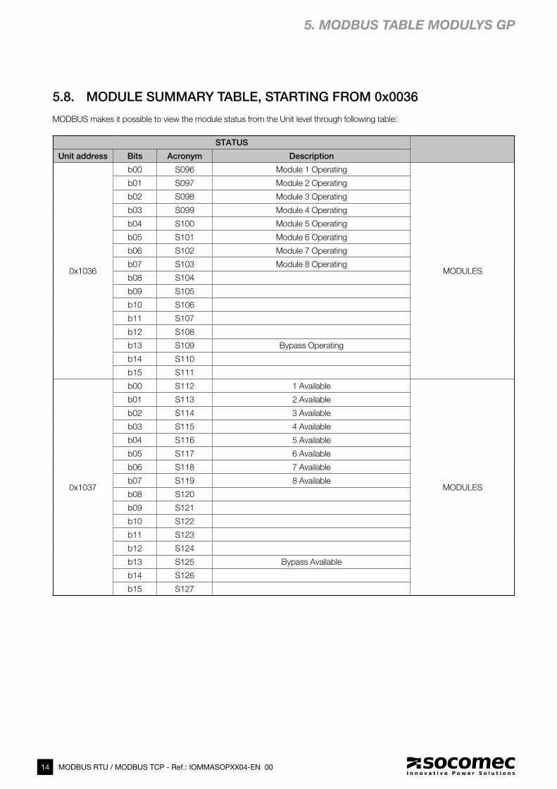
5.8. MODULE SUMMARY TABLE, STARTING FROM 0x0036
MODBUS makes it possible to view the module status from the Unit level through following table:
5. MODBUS TABLE MODULYS GP
15MODBUS RTU / MODBUS TCP - Ref.: IOMMASOPXX04-EN 00
EN
GL
ISH
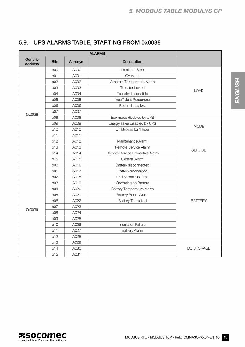
ALARMS
Generic
addressBits Acronym Description
0x0038
b00 A000 Imminent Stop
LOAD
b01 A001 Overload
b02 A002 Ambient Temperature Alarm
b03 A003 Transfer locked
b04 A004 Transfer impossible
b05 A005 Insufficient Resources
b06 A006 Redundancy lost
b07 A007
b08 A008 Eco mode disabled by UPS
MODEb09 A009 Energy saver disabled by UPS
b10 A010 On Bypass for 1 hour
b11 A011
b12 A012 Maintenance Alarm
SERVICEb13 A013 Remote Service Alarm
b14 A014 Remote Service Preventive Alarm
b15 A015 General Alarm
0x0039
b00 A016 Battery disconnected
BATTERY
b01 A017 Battery discharged
b02 A018 End of Backup Time
b03 A019 Operating on Battery
b04 A020 Battery Temperature Alarm
b05 A021 Battery Room Alarm
b06 A022 Battery Test failed
b07 A023
b08 A024
b09 A025
b10 A026 Insulation Failure
b11 A027 Battery Alarm
b12 A028
b13 A029
DC STORAGEb14 A030
b15 A031
5.9. UPS ALARMS TABLE, STARTING FROM 0x0038
5. MODBUS TABLE MODULYS GP
16 MODBUS RTU / MODBUS TCP - Ref.: IOMMASOPXX04-EN 00
ALARMS
Generic
addressBits Acronym Description
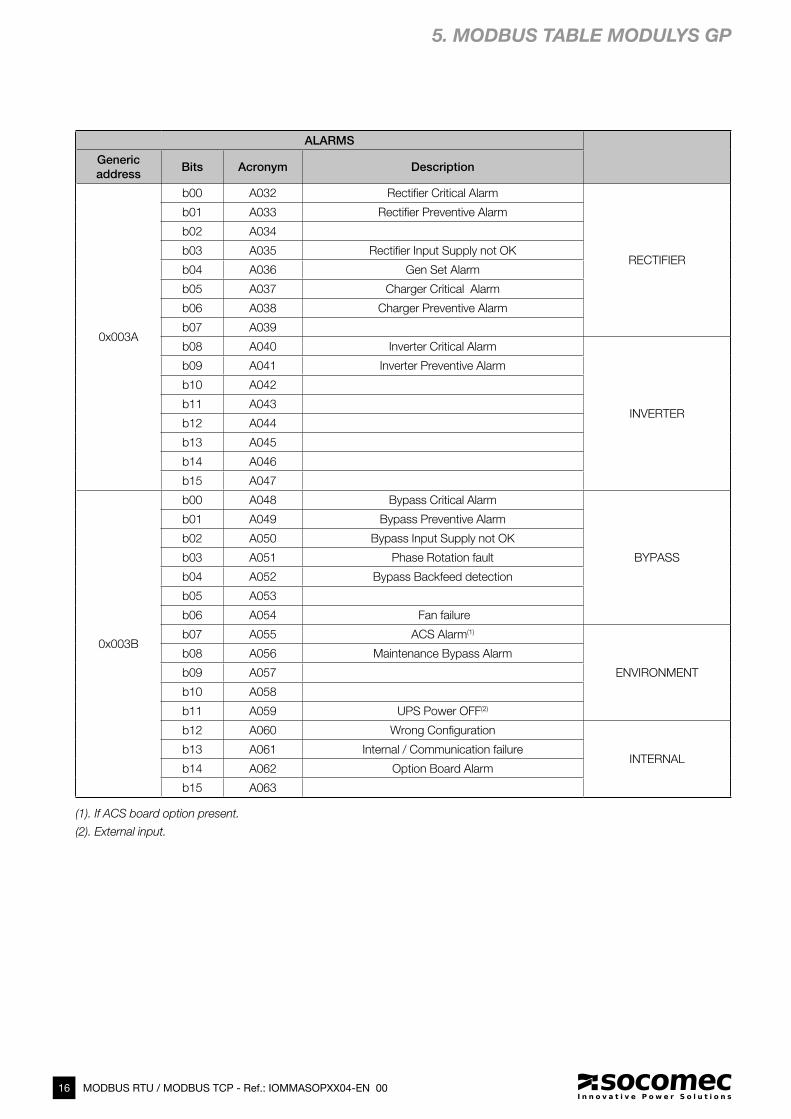
0x003A
b00 A032 Rectifier Critical Alarm
RECTIFIER
b01 A033 Rectifier Preventive Alarm
b02 A034
b03 A035 Rectifier Input Supply not OK
b04 A036 Gen Set Alarm
b05 A037 Charger Critical Alarm
b06 A038 Charger Preventive Alarm
b07 A039
b08 A040 Inverter Critical Alarm
INVERTER
b09 A041 Inverter Preventive Alarm
b10 A042
b11 A043
b12 A044
b13 A045
b14 A046
b15 A047
0x003B
b00 A048 Bypass Critical Alarm
BYPASS
b01 A049 Bypass Preventive Alarm
b02 A050 Bypass Input Supply not OK
b03 A051 Phase Rotation fault
b04 A052 Bypass Backfeed detection
b05 A053
b06 A054 Fan failure
b07 A055 ACS Alarm(1)
ENVIRONMENT
b08 A056 Maintenance Bypass Alarm
b09 A057
b10 A058
b11 A059 UPS Power OFF(2)
b12 A060 Wrong Configuration
INTERNALb13 A061 Internal / Communication failure
b14 A062 Option Board Alarm
b15 A063
5. MODBUS TABLE MODULYS GP
(1). If ACS board option present.
(2). External input.
17MODBUS RTU / MODBUS TCP - Ref.: IOMMASOPXX04-EN 00
EN
GL
ISH
ALARMS
Generic
addressBits Acronym Description
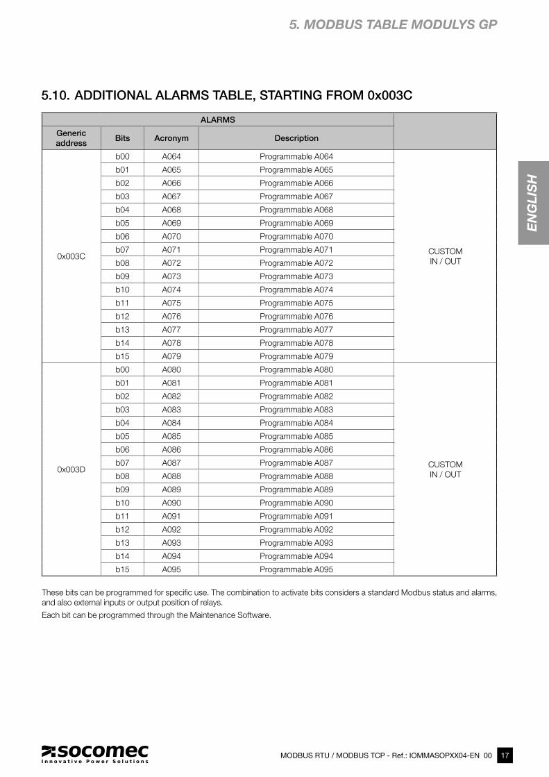
0x003C
b00 A064 Programmable A064
CUSTOM
IN / OUT
b01 A065 Programmable A065
b02 A066 Programmable A066
b03 A067 Programmable A067
b04 A068 Programmable A068
b05 A069 Programmable A069
b06 A070 Programmable A070
b07 A071 Programmable A071
b08 A072 Programmable A072
b09 A073 Programmable A073
b10 A074 Programmable A074
b11 A075 Programmable A075
b12 A076 Programmable A076
b13 A077 Programmable A077
b14 A078 Programmable A078
b15 A079 Programmable A079
0x003D
b00 A080 Programmable A080
CUSTOM
IN / OUT
b01 A081 Programmable A081
b02 A082 Programmable A082
b03 A083 Programmable A083
b04 A084 Programmable A084
b05 A085 Programmable A085
b06 A086 Programmable A086
b07 A087 Programmable A087
b08 A088 Programmable A088
b09 A089 Programmable A089
b10 A090 Programmable A090
b11 A091 Programmable A091
b12 A092 Programmable A092
b13 A093 Programmable A093
b14 A094 Programmable A094
b15 A095 Programmable A095
5.10. ADDITIONAL ALARMS TABLE, STARTING FROM 0x003C
These bits can be programmed for specific use. The combination to activate bits considers a standard Modbus status and alarms,
and also external inputs or output position of relays.
Each bit can be programmed through the Maintenance Software.
5. MODBUS TABLE MODULYS GP
18 MODBUS RTU / MODBUS TCP - Ref.: IOMMASOPXX04-EN 00
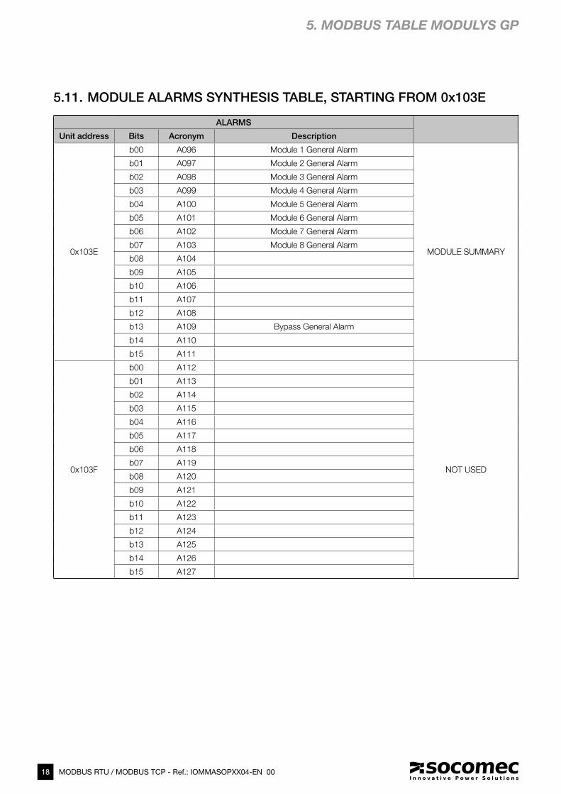
ALARMS
Unit address Bits Acronym Description
0x103E
b00 A096 Module 1 General Alarm
MODULE SUMMARY
b01 A097 Module 2 General Alarm
b02 A098 Module 3 General Alarm
b03 A099 Module 4 General Alarm
b04 A100 Module 5 General Alarm
b05 A101 Module 6 General Alarm
b06 A102 Module 7 General Alarm
b07 A103 Module 8 General Alarm
b08 A104
b09 A105
b10 A106
b11 A107
b12 A108
b13 A109 Bypass General Alarm
b14 A110
b15 A111
0x103F
b00 A112
NOT USED
b01 A113
b02 A114
b03 A115
b04 A116
b05 A117
b06 A118
b07 A119
b08 A120
b09 A121
b10 A122
b11 A123
b12 A124
b13 A125
b14 A126
b15 A127
5.11. MODULE ALARMS SYNTHESIS TABLE, STARTING FROM 0x103E
5. MODBUS TABLE MODULYS GP
19MODBUS RTU / MODBUS TCP - Ref.: IOMMASOPXX04-EN 00
EN
GL
ISHMeasurement Formats
Check
availabilityGeneric
addressAcronym Description Units 0x000E=0 0x000E=1
0x0040 M000 Output load rate % ### ###
OU
TP
UT
0x00C0
b09=0
0x0041 M001 Output load rate L1 % ### ###
0x0042 M002 Output load rate L2 % ### ###
0x0043 M003 Output load rate L3 % ### ###
0x0044 M004 Output Apparent Power kVA ## ### # ###.#
0x0045 M005 Output Active Power kW ## ### # ###.#
0x0046 M006 Output current L1 A ## ### # ###.#
0x0047 M007 Output current L2 A ## ### # ###.#
0x0048 M008 Output current L3 A ## ### # ###.#
0x0049 M009
0x004A M010 Output voltage L1 V ### ###
0x004B M011 Output voltage L2 V ### ###
0x004C M012 Output voltage L3 V ### ###
0x004D M013 Output frequency Hz ##.# ##.#
0x004E M014
0x004F M015 Ambient Temperature °C ##.# ##.#
0x0050 M016 Battery voltage string + V # ### ###.#
BA
TTE
RY
0x00C1
0x0051 M017 Battery voltage string - V # ### ###.#
0x0052 M018 Battery current string + A ## ### # ###.#
0x0053 M019 Battery current string - A ## ### # ###.#
0x0054 M020
0x0055 M021
0x0056 M022 Battery capacity % ### ###
0x0057 M023 Battery capacity Ah ## ### # ###.#
0x0058 M024 Bat. remaining backup time Mn ### ###
0x0059 M025 Time on battery s ### ###
0x005A M026 Battery temperature °C ##.# ##.#
0x005B M027 Battery temperature average °C ##.# ##.#
0x005C M028
0x005D M029
0x005E M030
0x005F M031
0x0060 M032 Rect. input supply volt. L1 V ### ###
RE
CT.
0x00C2
0x0061 M033 Rect. input supply volt. L2 V ### ###
0x0062 M034 Rect. input supply volt. L3 V ### ###
0x0063 M035 Rect. input supply freq. Hz ##.# ##.#
0x0064 M036 Rect. input supply volt. U12 V ### ###
0x0065 M037 Rect. input supply volt. U23 V ### ###
0x0066 M038 Rect. input supply volt. U31 V ### ###
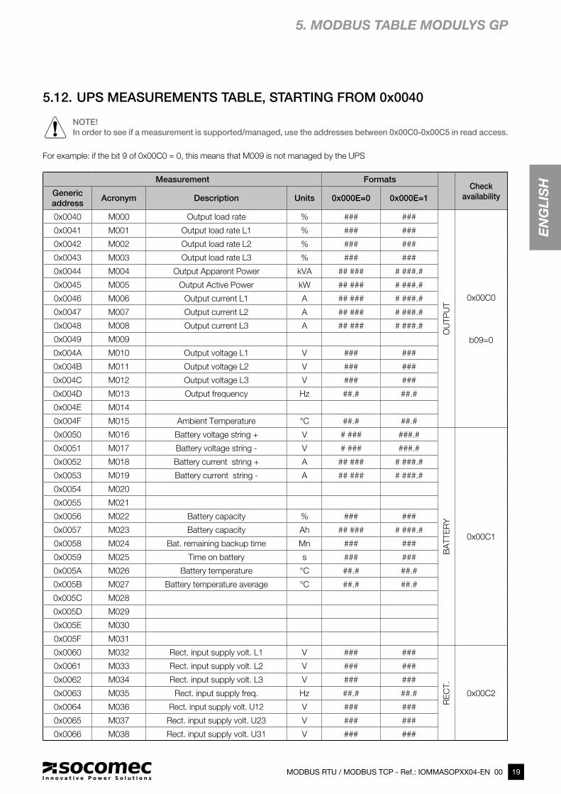
5.12. UPS MEASUREMENTS TABLE, STARTING FROM 0x0040
NOTE!
In order to see if a measurement is supported/managed, use the addresses between 0x00C0-0x00C5 in read access.
For example: if the bit 9 of 0x00C0 = 0, this means that M009 is not managed by the UPS
5. MODBUS TABLE MODULYS GP

20 MODBUS RTU / MODBUS TCP - Ref.: IOMMASOPXX04-EN 00
Measurement FormatsCheck
availabilityGeneric
addressAcronym Description Units 0x000E=0 0x000E=1
0x0067 M039 Bypass input supply voltage L1 V ### ###
BY
PA
SS
0x00C2
0x0068 M040 Bypass input supply voltage L2 V ### ###
0x0069 M041 Bypass input supply voltage L3 V ### ###
0x006A M042 Bypass input supply freq Hz ##.# ##.#
0x006B M043 Bypass input supply volt U12 V ### ###
0x006C M044 Bypass input supply volt U23 V ### ###
0x006D M045 Bypass input supply volt U31 V ### ###
0x006E M046
0x006F M047
0x0070 M048 Output Apparent P. L1 kVA ## ### # ###.#
OU
TP
UT D
ETA
IL
0x00C3
0x0071 M049 Output Apparent P. L2 kVA ## ### # ###.#
0x0072 M050 Output Apparent P. L3 kVA ## ### # ###.#
0x0073 M051 Output Active Power L1 kW ## ### # ###.#
0x0074 M052 Output Active Power L2 kW ## ### # ###.#
0x0075 M053 Output Active Power L3 kW ## ### # ###.#
0x0076 M054 Output voltage U12 V ### ###
0x0077 M055 Output voltage U23 V ### ###
0x0078 M056 Output voltage U31 V ### ###
0x0079 M057
0x007A M058
0x007B M059
0x007C M060
0x007D M061
0x007E M062
0x007F M063 Output Crest Factor neutral #.# #.#
0x0080 M064 Rectifier Input Current L1 A ## ### # ###.#
AD
D. IN
PU
T
0x00C4
0x0081 M065 Rectifier Input Current L2 A ## ### # ###.#
0x0082 M066 Rectifier Input Current L3 A ## ### # ###.#
0x0083 M067 Rectifier Active Power L1 kW ## ### # ###.#
0x0084 M068 Rectifier Active Power L2 kW ## ### # ###.#
0x0085 M069 Rectifier Active Power L3 kW ## ### # ###.#
0x0086 M070 Bypass Input Current L1 A ## ### # ###.#
0x0087 M071 Bypass Input Current L2 A ## ### # ###.#
0x0088 M072 Bypass Input Current L3 A ## ### # ###.#
0x0089 M073 Bypass Active Power L1 kW ## ### # ###.#
0x008A M074 Bypass Active Power L2 kW ## ### # ###.#
0x008B M075 Bypass Active Power L3 kW ## ### # ###.#
0x008C M076
0x008D M077 Reserved
0x008E M078 Reserved
0x008F M079 Reserved
5. MODBUS TABLE MODULYS GP
21MODBUS RTU / MODBUS TCP - Ref.: IOMMASOPXX04-EN 00
EN
GL
ISH
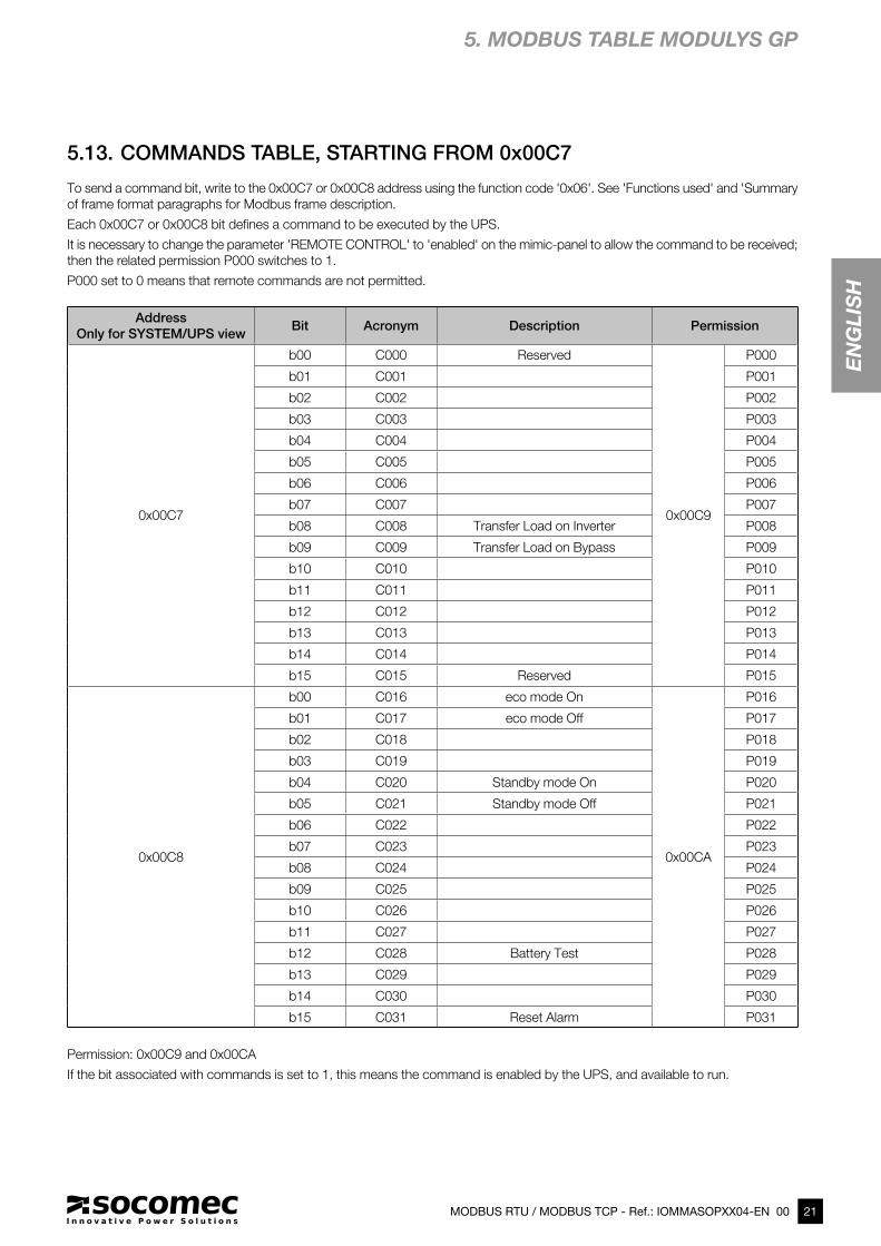
5.13. COMMANDS TABLE, STARTING FROM 0x00C7
To send a command bit, write to the 0x00C7 or 0x00C8 address using the function code '0x06'. See 'Functions used' and 'Summary
of frame format paragraphs for Modbus frame description.
Each 0x00C7 or 0x00C8 bit defines a command to be executed by the UPS.
It is necessary to change the parameter 'REMOTE CONTROL' to 'enabled' on the mimic-panel to allow the command to be received;
then the related permission P000 switches to 1.
P000 set to 0 means that remote commands are not permitted.
Address
Only for SYSTEM/UPS viewBit Acronym Description Permission
0x00C7
b00 C000 Reserved
0x00C9
P000
b01 C001 P001
b02 C002 P002
b03 C003 P003
b04 C004 P004
b05 C005 P005
b06 C006 P006
b07 C007 P007
b08 C008 Transfer Load on Inverter P008
b09 C009 Transfer Load on Bypass P009
b10 C010 P010
b11 C011 P011
b12 C012 P012
b13 C013 P013
b14 C014 P014
b15 C015 Reserved P015
0x00C8
b00 C016 eco mode On
0x00CA
P016
b01 C017 eco mode Off P017
b02 C018 P018
b03 C019 P019
b04 C020 Standby mode On P020
b05 C021 Standby mode Off P021
b06 C022 P022
b07 C023 P023
b08 C024 P024
b09 C025 P025
b10 C026 P026
b11 C027 P027
b12 C028 Battery Test P028
b13 C029 P029
b14 C030 P030
b15 C031 Reset Alarm P031
Permission: 0x00C9 and 0x00CA
If the bit associated with commands is set to 1, this means the command is enabled by the UPS, and available to run.
5. MODBUS TABLE MODULYS GP
22 MODBUS RTU / MODBUS TCP - Ref.: IOMMASOPXX04-EN 00
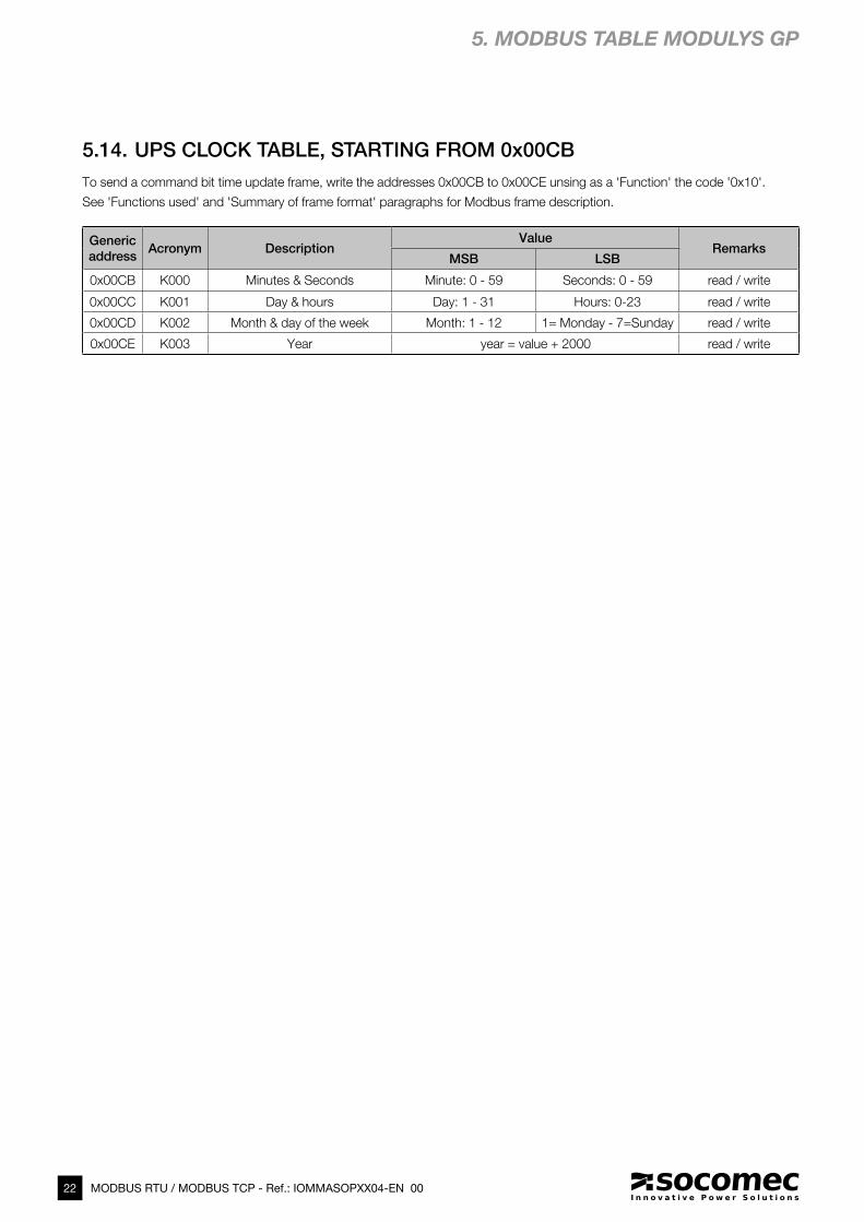
5.14. UPS CLOCK TABLE, STARTING FROM 0x00CB
Generic
addressAcronym Description
ValueRemarks
MSB LSB
0x00CB K000 Minutes & Seconds Minute: 0 - 59 Seconds: 0 - 59 read / write
0x00CC K001 Day & hours Day: 1 - 31 Hours: 0-23 read / write
0x00CD K002 Month & day of the week Month: 1 - 12 1= Monday - 7=Sunday read / write
0x00CE K003 Year year = value + 2000 read / write
To send a command bit time update frame, write the addresses 0x00CB to 0x00CE unsing as a 'Function' the code '0x10'.
See 'Functions used' and 'Summary of frame format' paragraphs for Modbus frame description.
5. MODBUS TABLE MODULYS GP
23MODBUS RTU / MODBUS TCP - Ref.: IOMMASOPXX04-EN 00
EN
GL
ISH
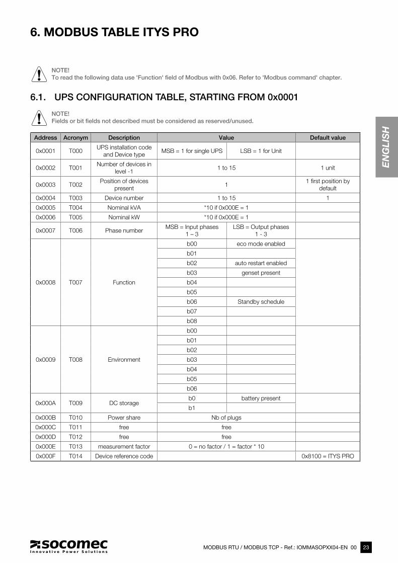
6. MODBUS TABLE ITYS PRO
Address Acronym Description Value Default value
0x0001 T000UPS installation code
and Device typeMSB = 1 for single UPS LSB = 1 for Unit
0x0002 T001Number of devices in
level -11 to 15 1 unit
0x0003 T002Position of devices
present1
1 first position by
default
0x0004 T003 Device number 1 to 15 1
0x0005 T004 Nominal kVA *10 if 0x000E = 1
0x0006 T005 Nominal kW *10 if 0x000E = 1
0x0007 T006 Phase numberMSB = Input phases
1 – 3
LSB = Output phases
1 - 3
0x0008 T007 Function
b00 eco mode enabled
b01
b02 auto restart enabled
b03 genset present
b04
b05
b06 Standby schedule
b07
b08
0x0009 T008 Environment
b00
b01
b02
b03
b04
b05
b06
0x000A T009 DC storageb0 battery present
b1
0x000B T010 Power share Nb of plugs
0x000C T011 free free
0x000D T012 free free
0x000E T013 measurement factor 0 = no factor / 1 = factor * 10
0x000F T014 Device reference code 0x8100 = ITYS PRO
NOTE!
To read the following data use 'Function' field of Modbus with 0x06. Refer to 'Modbus command' chapter.
6.1. UPS CONFIGURATION TABLE, STARTING FROM 0x0001
NOTE!
Fields or bit fields not described must be considered as reserved/unused.
24 MODBUS RTU / MODBUS TCP - Ref.: IOMMASOPXX04-EN 00
6. MODBUS TABLE ITYS PRO
Address Acronym DescriptionValue
CommentsLength Number of ASCII char.
0x0010 I000 SERIAL NUMBER 10 20 MSB = first char of string
0x001A I001 SOCOMEC REFERENCE 10 20 MSB = first char of string
0x0024 I002 USER DEVICE REFERENCE 6 12 MSB = first char of string
0x002A I003 USER DEVICE LOCATION 6 12 MSB = first char of string
6.2. UPS REFERENCE TABLE, STARTING FROM 0x0010
STATUS
Generic
addressBits Acronym Description
0x0030
b00 S000 Load protected by Inverter
OUTPUT STATUS
b01 S001
b02 S002 Load supplied by automatic Bypass
b03 S003
b04 S004 Load OFF
b05 S005
b06 S006 In eco mode
FUNCTIONING
MODE
b07 S007
b08 S008
b09 S009 Service Mode
b10 S010
b11 S011 Operating
DEVICE STATUS
b12 S012 Available
b13 S013 On Standby
b14 S014
b15 S015 Maintenance Alert
0x0031
b00 S016 Output Breaker closed
DEVICE
ENVIRONMENT
b01 S017
b02 S018
b03 S019
b04 S020
b05 S021
b06 S022
b07 S023 Gen set ON
b08 S024
b09 S025
b10 S026 Automatic Start in progress
PROCEDURES
b11 S027
b12 S028 UPS OFF procedure in progress
b13 S029
b14 S030
b15 S031 Alarm Ack. request
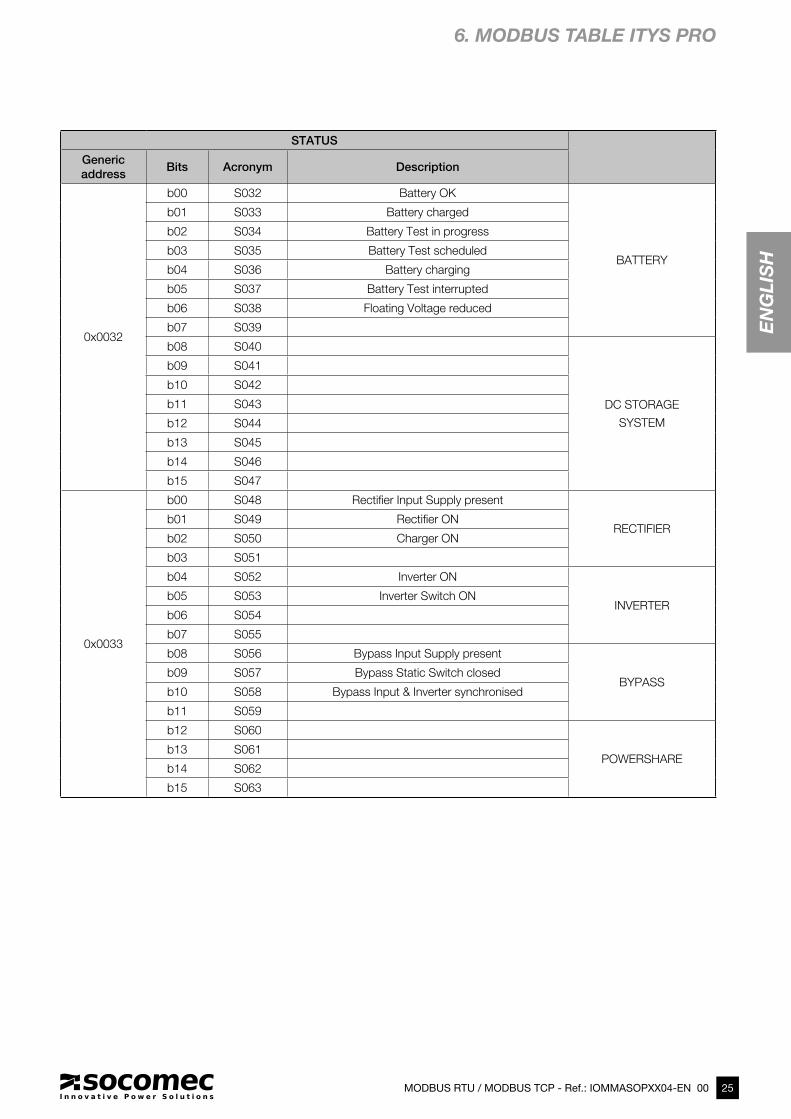
6.3. UPS STATUS TABLE, STARTING FROM 0x0030
25MODBUS RTU / MODBUS TCP - Ref.: IOMMASOPXX04-EN 00
EN
GL
ISH
6. MODBUS TABLE ITYS PRO
STATUS
Generic
addressBits Acronym Description
0x0032
b00 S032 Battery OK
BATTERY
b01 S033 Battery charged
b02 S034 Battery Test in progress
b03 S035 Battery Test scheduled
b04 S036 Battery charging
b05 S037 Battery Test interrupted
b06 S038 Floating Voltage reduced
b07 S039
b08 S040
DC STORAGE
SYSTEM
b09 S041
b10 S042
b11 S043
b12 S044
b13 S045
b14 S046
b15 S047
0x0033
b00 S048 Rectifier Input Supply present
RECTIFIER b01 S049 Rectifier ON
b02 S050 Charger ON
b03 S051
b04 S052 Inverter ON
INVERTERb05 S053 Inverter Switch ON
b06 S054
b07 S055
b08 S056 Bypass Input Supply present
BYPASSb09 S057 Bypass Static Switch closed
b10 S058 Bypass Input & Inverter synchronised
b11 S059
b12 S060
POWERSHAREb13 S061
b14 S062
b15 S063
26 MODBUS RTU / MODBUS TCP - Ref.: IOMMASOPXX04-EN 00
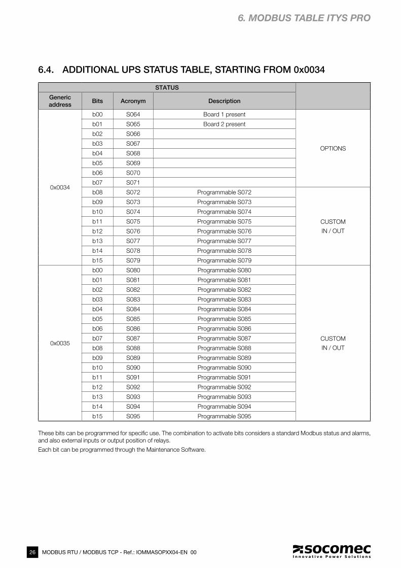
6. MODBUS TABLE ITYS PRO
STATUS
Generic
addressBits Acronym Description
0x0034
b00 S064 Board 1 present
OPTIONS
b01 S065 Board 2 present
b02 S066
b03 S067
b04 S068
b05 S069
b06 S070
b07 S071
b08 S072 Programmable S072
CUSTOM
IN / OUT
b09 S073 Programmable S073
b10 S074 Programmable S074
b11 S075 Programmable S075
b12 S076 Programmable S076
b13 S077 Programmable S077
b14 S078 Programmable S078
b15 S079 Programmable S079
0x0035
b00 S080 Programmable S080
CUSTOM
IN / OUT
b01 S081 Programmable S081
b02 S082 Programmable S082
b03 S083 Programmable S083
b04 S084 Programmable S084
b05 S085 Programmable S085
b06 S086 Programmable S086
b07 S087 Programmable S087
b08 S088 Programmable S088
b09 S089 Programmable S089
b10 S090 Programmable S090
b11 S091 Programmable S091
b12 S092 Programmable S092
b13 S093 Programmable S093
b14 S094 Programmable S094
b15 S095 Programmable S095
6.4. ADDITIONAL UPS STATUS TABLE, STARTING FROM 0x0034
These bits can be programmed for specific use. The combination to activate bits considers a standard Modbus status and alarms,
and also external inputs or output position of relays.
Each bit can be programmed through the Maintenance Software.

27MODBUS RTU / MODBUS TCP - Ref.: IOMMASOPXX04-EN 00
EN
GL
ISH
6. MODBUS TABLE ITYS PRO
ALARMS
Address Bits Acronym Description
0x0038
b00 A000 Imminent Stop
LOAD
b01 A001 Overload
b02 A002 Ambient Temperature Alarm
b03 A003 Transfer locked
b04 A004 Transfer impossible
b05 A005
b06 A006
b07 A007
b08 A008
MODEb09 A009
b10 A010
b11 A011
b12 A012 Maintenance Alarm
SERVICEb13 A013 Remote Service Alarm
b14 A014 Remote Service Preventive Alarm
b15 A015 General Alarm
0x0039
b00 A016 Battery disconnected
BATTERY
b01 A017 Battery discharged
b02 A018 End of Backup Time
b03 A019 Operating on Battery
b04 A020 Battery Temperature Alarm
b05 A021 Battery Room Alarm
b06 A022 Battery Test failed
b07 A023
b08 A024
b09 A025
b10 A026
b11 A027 Battery Alarm
b12 A028
b13 A029
DC STORAGEb14 A030
b15 A031
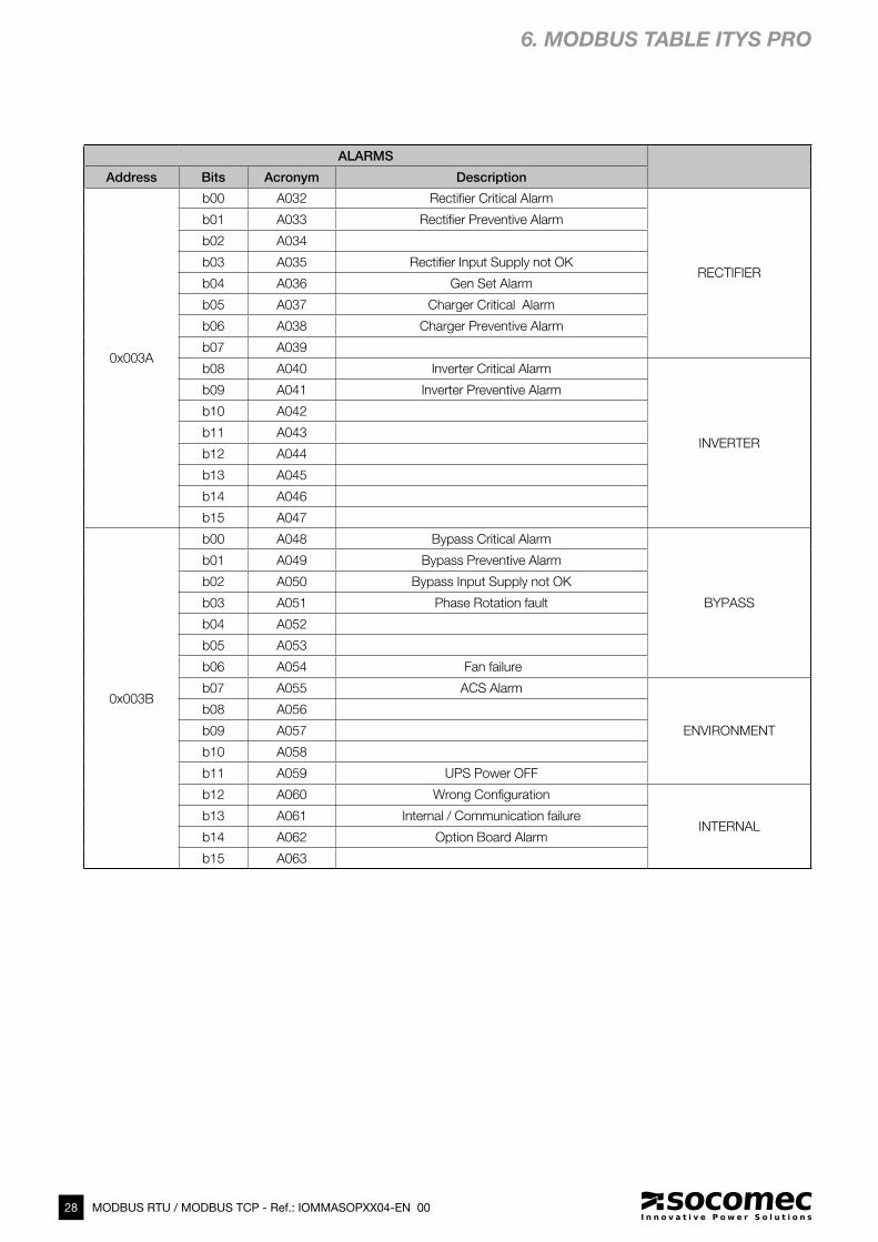
6.5. UPS ALARMS TABLE, STARTING FROM 0x0038
28 MODBUS RTU / MODBUS TCP - Ref.: IOMMASOPXX04-EN 00
6. MODBUS TABLE ITYS PRO
ALARMS
Address Bits Acronym Description
0x003A
b00 A032 Rectifier Critical Alarm
RECTIFIER
b01 A033 Rectifier Preventive Alarm
b02 A034
b03 A035 Rectifier Input Supply not OK
b04 A036 Gen Set Alarm
b05 A037 Charger Critical Alarm
b06 A038 Charger Preventive Alarm
b07 A039
b08 A040 Inverter Critical Alarm
INVERTER
b09 A041 Inverter Preventive Alarm
b10 A042
b11 A043
b12 A044
b13 A045
b14 A046
b15 A047
0x003B
b00 A048 Bypass Critical Alarm
BYPASS
b01 A049 Bypass Preventive Alarm
b02 A050 Bypass Input Supply not OK
b03 A051 Phase Rotation fault
b04 A052
b05 A053
b06 A054 Fan failure
b07 A055 ACS Alarm
ENVIRONMENT
b08 A056
b09 A057
b10 A058
b11 A059 UPS Power OFF
b12 A060 Wrong Configuration
INTERNALb13 A061 Internal / Communication failure
b14 A062 Option Board Alarm
b15 A063
29MODBUS RTU / MODBUS TCP - Ref.: IOMMASOPXX04-EN 00
EN
GL
ISH
6. MODBUS TABLE ITYS PRO
ALARMS
Generic
addressBits Acronym Description
0x003C
b00 A064 Programmable A064
CUSTOM
IN / OUT
b01 A065 Programmable A065
b02 A066 Programmable A066
b03 A067 Programmable A067
b04 A068 Programmable A068
b05 A069 Programmable A069
b06 A070 Programmable A070
b07 A071 Programmable A071
b08 A072 Programmable A072
b09 A073 Programmable A073
b10 A074 Programmable A074
b11 A075 Programmable A075
b12 A076 Programmable A076
b13 A077 Programmable A077
b14 A078 Programmable A078
b15 A079 Programmable A079
0x003D
b00 A080 Programmable A080
CUSTOM
IN / OUT
b01 A081 Programmable A081
b02 A082 Programmable A082
b03 A083 Programmable A083
b04 A084 Programmable A084
b05 A085 Programmable A085
b06 A086 Programmable A086
b07 A087 Programmable A087
b08 A088 Programmable A088
b09 A089 Programmable A089
b10 A090 Programmable A090
b11 A091 Programmable A091
b12 A092 Programmable A092
b13 A093 Programmable A093
b14 A094 Programmable A094
b15 A095 Programmable A095
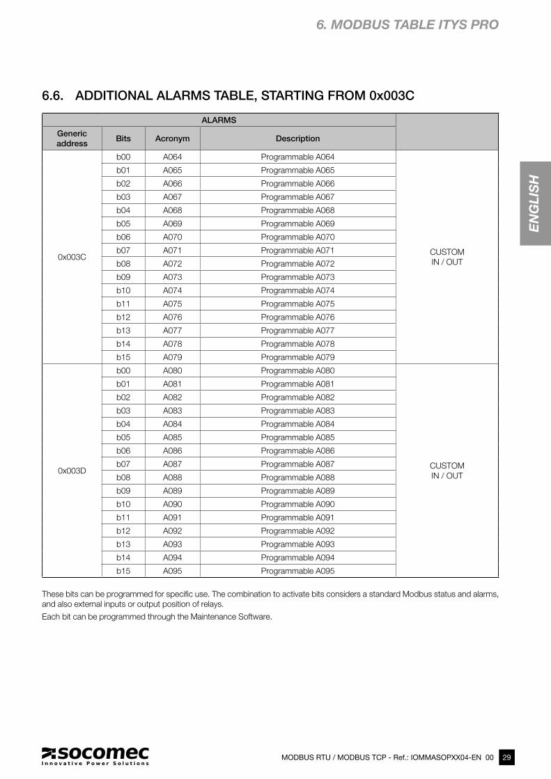
6.6. ADDITIONAL ALARMS TABLE, STARTING FROM 0x003C
These bits can be programmed for specific use. The combination to activate bits considers a standard Modbus status and alarms,
and also external inputs or output position of relays.
Each bit can be programmed through the Maintenance Software.
30 MODBUS RTU / MODBUS TCP - Ref.: IOMMASOPXX04-EN 00
6. MODBUS TABLE ITYS PRO
Measurements Formats Check avai-
labilityAddress Acronym Description Units 0x000E=0 0x000E=1
0x0040 M000 Output load rate % ### ###
OU
TP
UT
0x00C0
0x0041 M001 Output load rate L1 % ### ###
0x0042 M002 Output load rate L2 % ### ###
0x0043 M003 Output load rate L3 % ### ###
0x0044 M004 Output Apparent Power kVA ## ### # ###.#
0x0045 M005 Output Active Power kW ## ### # ###.#
0x0046 M006 Output current L1 A ## ### # ###.#
0x0047 M007 Output current L2 A ## ### # ###.#
0x0048 M008 Output current L3 A ## ### # ###.#
0x0049 M009 Output neutral current A ## ### # ###.#
0x004A M010 Output voltage L1 V ### ###
0x004B M011 Output voltage L2 V ### ###
0x004C M012 Output voltage L3 V ### ###
0x004D M013 Output frequency Hz ##.# ##.#
0x004E M014
0x004F M015 Ambient Temperature °C ##.# ##.#
0x0050 M016 Battery voltage string + V # ### ###.#
BA
TTE
RY
0x00C1
0x0051 M017 Battery voltage string - V # ### ###.#
0x0052 M018 Battery current string + A ## ### # ###.#
0x0053 M019 Battery current string - A ## ### # ###.#
0x0054 M020
0x0055 M021
0x0056 M022 Battery capacity % ### ###
0x0057 M023 Battery capacity Ah ## ### # ###.#
0x0058 M024 Bat. remaining backup time Mn ### ###
0x0059 M025 Time on battery s ### ###
0x005A M026 Battery temperature °C ##.# ##.#
0x005B M027 Battery temperature average °C ##.# ##.#
0x005C M028 DC Storage voltage V # ### ###.#
0x005D M029 DC Storage temperature °C ##.# ##.#
0x005E M030
0x005F M031
0x0060 M032 Rect. input supply volt. L1 V ### ###
RE
CT.
0x00C2
0x0061 M033 Rect. input supply volt. L2 V ### ###
0x0062 M034 Rect. input supply volt. L3 V ### ###
0x0063 M035 Rect. input supply freq. Hz ##.# ##.#
0x0064 M036 Rect. input supply volt. U12 V ### ###
0x0065 M037 Rect. input supply volt. U23 V ### ###
0x0066 M038 Rect. input supply volt. U31 V ### ###
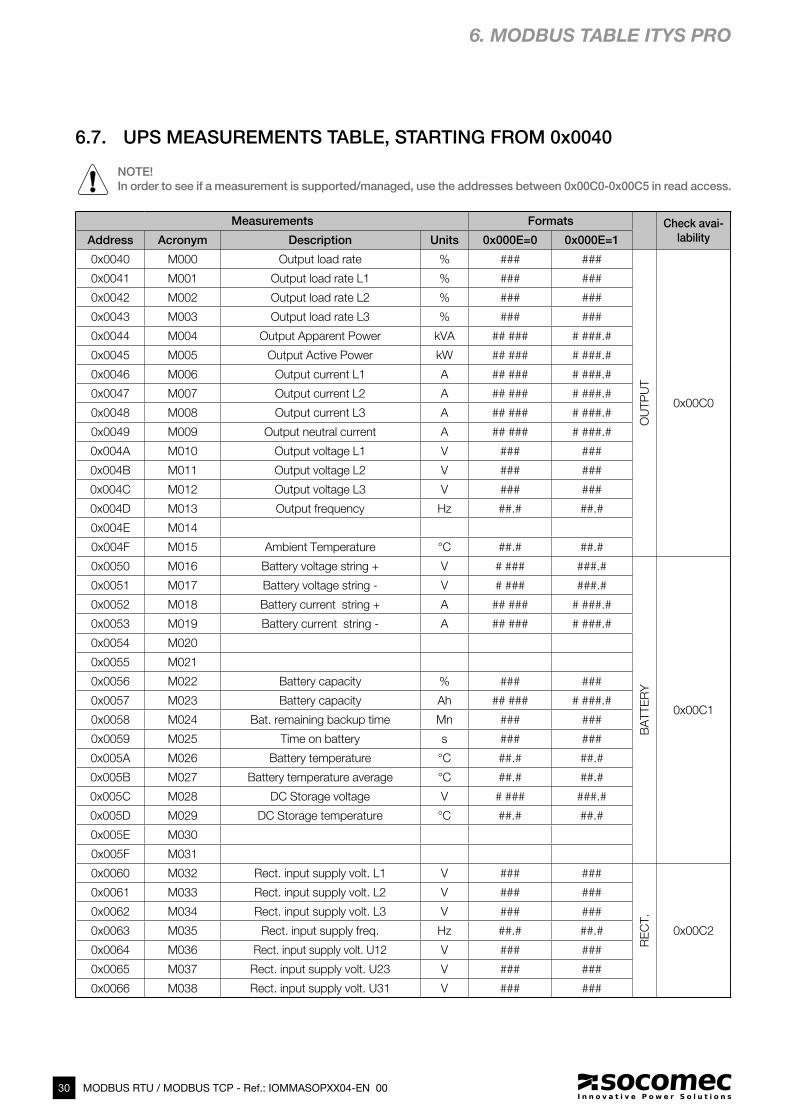
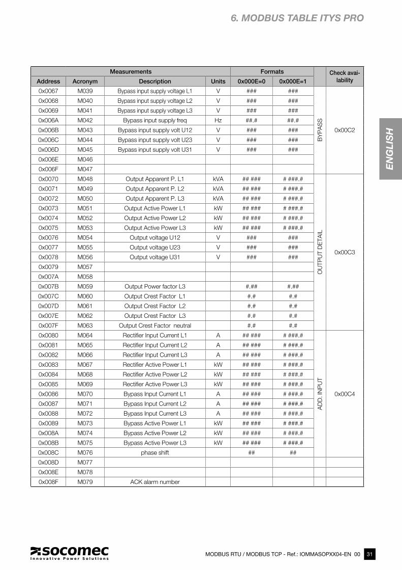
6.7. UPS MEASUREMENTS TABLE, STARTING FROM 0x0040
NOTE!
In order to see if a measurement is supported/managed, use the addresses between 0x00C0-0x00C5 in read access.
31MODBUS RTU / MODBUS TCP - Ref.: IOMMASOPXX04-EN 00
EN
GL
ISH
Measurements Formats Check avai-
labilityAddress Acronym Description Units 0x000E=0 0x000E=1
0x0067 M039 Bypass input supply voltage L1 V ### ###
BY
PA
SS
0x00C2
0x0068 M040 Bypass input supply voltage L2 V ### ###
0x0069 M041 Bypass input supply voltage L3 V ### ###
0x006A M042 Bypass input supply freq Hz ##.# ##.#
0x006B M043 Bypass input supply volt U12 V ### ###
0x006C M044 Bypass input supply volt U23 V ### ###
0x006D M045 Bypass input supply volt U31 V ### ###
0x006E M046
0x006F M047
0x0070 M048 Output Apparent P. L1 kVA ## ### # ###.#
OU
TP
UT D
ETA
IL
0x00C3
0x0071 M049 Output Apparent P. L2 kVA ## ### # ###.#
0x0072 M050 Output Apparent P. L3 kVA ## ### # ###.#
0x0073 M051 Output Active Power L1 kW ## ### # ###.#
0x0074 M052 Output Active Power L2 kW ## ### # ###.#
0x0075 M053 Output Active Power L3 kW ## ### # ###.#
0x0076 M054 Output voltage U12 V ### ###
0x0077 M055 Output voltage U23 V ### ###
0x0078 M056 Output voltage U31 V ### ###
0x0079 M057
0x007A M058
0x007B M059 Output Power factor L3 #.## #.##
0x007C M060 Output Crest Factor L1 #.# #.#
0x007D M061 Output Crest Factor L2 #.# #.#
0x007E M062 Output Crest Factor L3 #.# #.#
0x007F M063 Output Crest Factor neutral #.# #.#
0x0080 M064 Rectifier Input Current L1 A ## ### # ###.#
AD
D. IN
PU
T
0x00C4
0x0081 M065 Rectifier Input Current L2 A ## ### # ###.#
0x0082 M066 Rectifier Input Current L3 A ## ### # ###.#
0x0083 M067 Rectifier Active Power L1 kW ## ### # ###.#
0x0084 M068 Rectifier Active Power L2 kW ## ### # ###.#
0x0085 M069 Rectifier Active Power L3 kW ## ### # ###.#
0x0086 M070 Bypass Input Current L1 A ## ### # ###.#
0x0087 M071 Bypass Input Current L2 A ## ### # ###.#
0x0088 M072 Bypass Input Current L3 A ## ### # ###.#
0x0089 M073 Bypass Active Power L1 kW ## ### # ###.#
0x008A M074 Bypass Active Power L2 kW ## ### # ###.#
0x008B M075 Bypass Active Power L3 kW ## ### # ###.#
0x008C M076 phase shift ## ##
0x008D M077
0x008E M078
0x008F M079 ACK alarm number
6. MODBUS TABLE ITYS PRO
32 MODBUS RTU / MODBUS TCP - Ref.: IOMMASOPXX04-EN 00
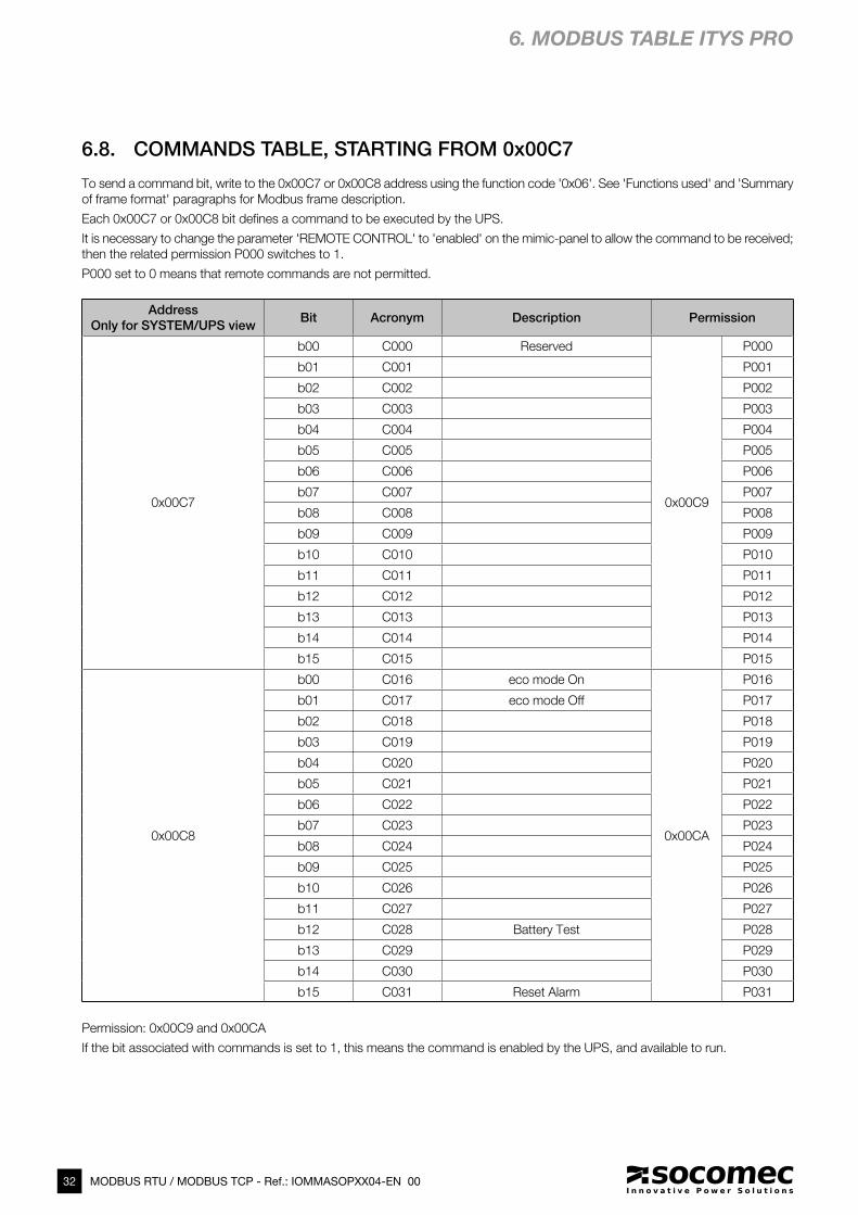
6.8. COMMANDS TABLE, STARTING FROM 0x00C7
To send a command bit, write to the 0x00C7 or 0x00C8 address using the function code '0x06'. See 'Functions used' and 'Summary
of frame format' paragraphs for Modbus frame description.
Each 0x00C7 or 0x00C8 bit defines a command to be executed by the UPS.
It is necessary to change the parameter 'REMOTE CONTROL' to 'enabled' on the mimic-panel to allow the command to be received;
then the related permission P000 switches to 1.
P000 set to 0 means that remote commands are not permitted.
Address
Only for SYSTEM/UPS viewBit Acronym Description Permission
0x00C7
b00 C000 Reserved
0x00C9
P000
b01 C001 P001
b02 C002 P002
b03 C003 P003
b04 C004 P004
b05 C005 P005
b06 C006 P006
b07 C007 P007
b08 C008 P008
b09 C009 P009
b10 C010 P010
b11 C011 P011
b12 C012 P012
b13 C013 P013
b14 C014 P014
b15 C015 P015
0x00C8
b00 C016 eco mode On
0x00CA
P016
b01 C017 eco mode Off P017
b02 C018 P018
b03 C019 P019
b04 C020 P020
b05 C021 P021
b06 C022 P022
b07 C023 P023
b08 C024 P024
b09 C025 P025
b10 C026 P026
b11 C027 P027
b12 C028 Battery Test P028
b13 C029 P029
b14 C030 P030
b15 C031 Reset Alarm P031
Permission: 0x00C9 and 0x00CA
If the bit associated with commands is set to 1, this means the command is enabled by the UPS, and available to run.
6. MODBUS TABLE ITYS PRO
33MODBUS RTU / MODBUS TCP - Ref.: IOMMASOPXX04-EN 00
EN
GL
ISH
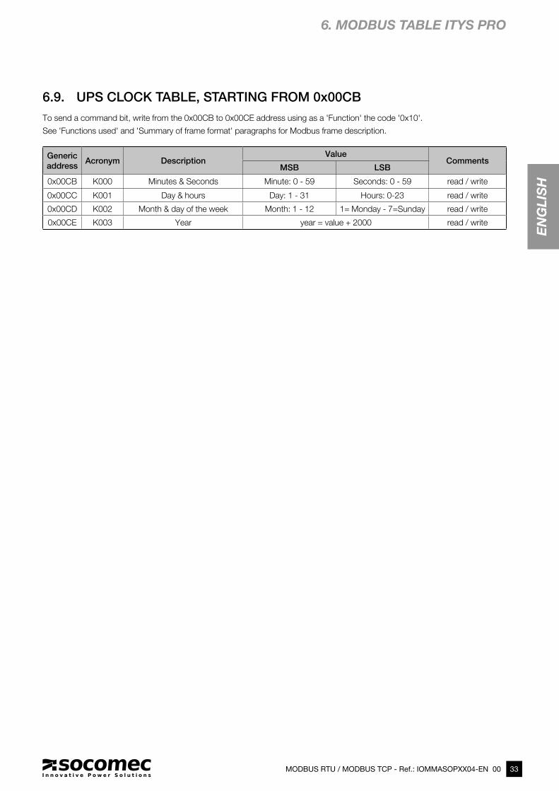
6.9. UPS CLOCK TABLE, STARTING FROM 0x00CB
Generic
addressAcronym Description
ValueComments
MSB LSB
0x00CB K000 Minutes & Seconds Minute: 0 - 59 Seconds: 0 - 59 read / write
0x00CC K001 Day & hours Day: 1 - 31 Hours: 0-23 read / write
0x00CD K002 Month & day of the week Month: 1 - 12 1= Monday - 7=Sunday read / write
0x00CE K003 Year year = value + 2000 read / write
6. MODBUS TABLE ITYS PRO
To send a command bit, write from the 0x00CB to 0x00CE address using as a 'Function' the code '0x10'.
See 'Functions used' and 'Summary of frame format' paragraphs for Modbus frame description.
34 MODBUS RTU / MODBUS TCP - Ref.: IOMMASOPXX04-EN 00
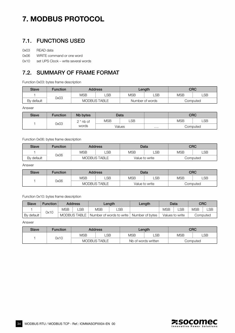
7. MODBUS PROTOCOL
7.1. FUNCTIONS USED
0x03 READ data
0x06 WRITE command or one word
0x10 set UPS Clock – write several words
7.2. SUMMARY OF FRAME FORMAT
Function 0x03: bytes frame description
Slave Function Address Length CRC
10x03
MSB LSB MSB LSB MSB LSB
By default MODBUS TABLE Number of words Computed
Answer
Slave Function Nb bytes Data CRC
1 0x032 * nb of
words
MSB LSB MSB LSB
Values …. Computed
Function 0x06: bytes frame description
Slave Function Address Data CRC
10x06
MSB LSB MSB LSB MSB LSB
By default MODBUS TABLE Value to write Computed
Answer
Slave Function Address Data CRC
1 0x06MSB LSB MSB LSB MSB LSB
MODBUS TABLE Value to write Computed
Function 0x10: bytes frame description
Slave Function Address Length Length Data CRC
10x10
MSB LSB MSB LSB MSB LSB MSB LSB
By default MODBUS TABLE Number of words to write Number of bytes Values to write Computed
Answer
Slave Function Address Length CRC
1 0x10MSB LSB MSB LSB MSB LSB
MODBUS TABLE Nb of words written Computed
35MODBUS RTU / MODBUS TCP - Ref.: IOMMASOPXX04-EN 00
EN
GL
ISH
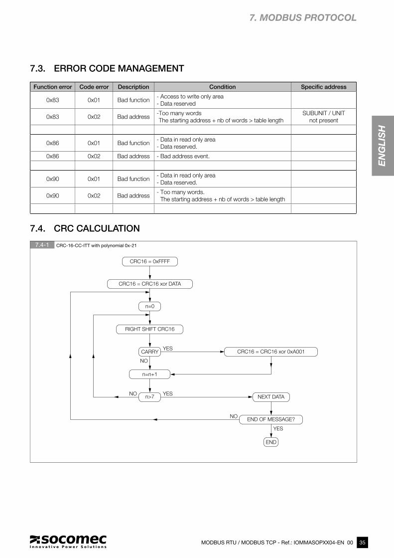
7.4-1 CRC-16-CC-ITT with polynomial 0x-21
7.3. ERROR CODE MANAGEMENT
Function error Code error Description Condition Specific address
0x83 0x01 Bad function- Access to write only area
- Data reserved
0x83 0x02 Bad address- Too many words
The starting address + nb of words > table length
SUBUNIT / UNIT
not present
0x86 0x01 Bad function- Data in read only area
- Data reserved.
0x86 0x02 Bad address - Bad address event.
0x90 0x01 Bad function- Data in read only area
- Data reserved.
0x90 0x02 Bad address- Too many words.
The starting address + nb of words > table length
7.4. CRC CALCULATION
7. MODBUS PROTOCOL
CRC16 = 0xFFFF
RIGHT SHIFT CRC16
CRC16 = CRC16 xor DATA
CRC16 = CRC16 xor 0xA001CARRY
n=n+1
n>7 NEXT DATA
END OF MESSAGE?
END
YES
NO
n=0
NO
NO
YES
YES

36 MODBUS RTU / MODBUS TCP - Ref.: IOMMASOPXX04-EN 00
8-1 Discovery tools
8-2 IP settings
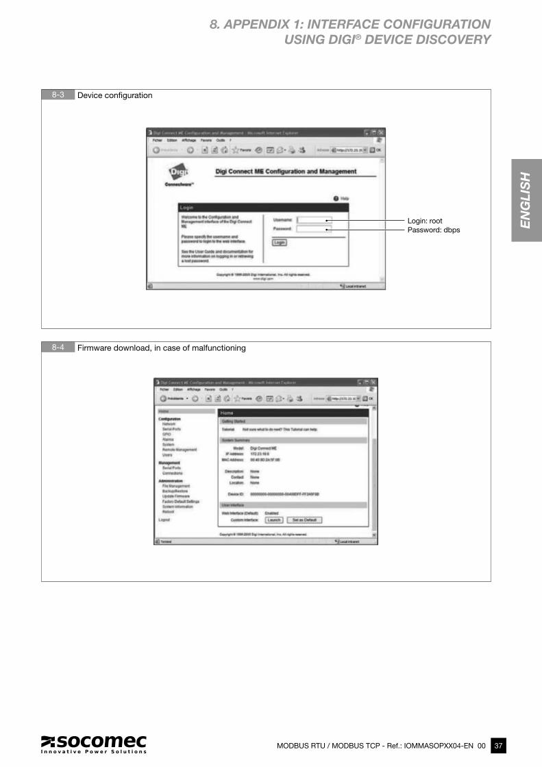
8. APPENDIX 1: INTERFACE CONFIGURATION
USING DIGI® DEVICE DISCOVERY
37
EN
GL
ISH
MODBUS RTU / MODBUS TCP - Ref.: IOMMASOPXX04-EN 00
8-3 Device confi guration
8-4 Firmware download, in case of malfunctioning
Password: dbps
Login: root
8. APPENDIX 1: INTERFACE CONFIGURATION USING DIGI® DEVICE DISCOVERY
38 MODBUS RTU / MODBUS TCP - Ref.: IOMMASOPXX04-EN 00
The frames below are only examples:
REQUEST FROM MASTER MODBUS TCP
Original frame: 01 03 1034 0003 40C5
Encapsulated frame: 0046 0000 0006 01 03 1034 0003
where:
0046 corresponds to the transaction number
0000 corresponds to the protocol identifier
0006 corresponds to the number of bytes (length of the message)
Note: the CRC is removed in the encapsulated MODBUS frame.
REPLY FROM THE UPS MODBUS TCP:
Original frame: 01 03 06 0002 0184 0000 1960
Encapsulated frame: 0046 0000 0009 01 03 06 0002 0184 0000
where:
0046 corresponds to the transaction number
0000 corresponds to the protocol identifier
0006 corresponds to the number of bytes (length of the message)
Note: the CRC is removed in the encapsulated MODBUS frame.
9. APPENDIX 2: MODBUS TCP IDA SPECIFICATION


www.socomec.com
HEAD OFFICE
SOCOMEC GROUPS.A. SOCOMEC capital 10 816 800€ R.C.S. Strasbourg B 548 500 149 B.P. 60010 - 1, rue de Westhouse F-67235 Benfeld Cedex - FRANCE Tel. +33 3 88 57 41 41 Fax +33 3 88 74 08 00 [email protected]
Socomec worldwide
BELGIUM
SolarTel. +32 2 340 02 30 Fax +32 2 346 28 99 [email protected]
FRANCE
SolarTel. +33 1 45 14 63 00 Fax +33 1 48 67 31 12 [email protected]
GERMANYPower Control & Energy EfficiencyTel. +49 7243 65292 0 Fax +49 7243 65292 13 [email protected]
UPSTel. +49 621 71 68 40 Fax +49 621 71 68 444 [email protected]
ITALYPower Control & Energy EfficiencyTel.+39 02 98 49 821 Fax +39 02 98 24 33 10 [email protected]
SolarTel. +39 0444 598611 Fax +39 0444 598627 [email protected]
UPS Tel.+39 02 98 242 942 Fax +39 02 98 240 723 [email protected]
NETHERLANDS
SolarTel. +31 30 760 0900 Fax +31 30 637 2166 [email protected]
POLANDPower Control & Energy EfficiencyTel. +48 91 442 64 11 Fax +48 91 442 64 19 [email protected]
UPSTel. +48 22 825 73 60 Fax. +48 22 825 73 60 [email protected]
PORTUGALUPS / SolarTel.+351 261 812 599 Fax +351 261 812 570 [email protected]
ROMANIA
SolarTel. +40 21 319 36 88 Fax +40 21 319 36 89 [email protected]
RUSSIA
SolarTel. +7 495 775 19 85 Fax +7 495 775 19 85 [email protected]
SLOVENIA
SolarTel. +386 1 5807 860 Fax +386 1 561 11 73 [email protected]
SPAIN
SolarTel. +34 93 540 75 75 Fax +34 93 540 75 76 [email protected]
UNITED KINGDOMPower Control & Energy EfficiencyTel. +44 1462 440 033 Fax +44 1462 431 143 [email protected]
UPSTel.+44 1285 863 300 Fax+44 1285 862 304 [email protected]
TURKEY
SolarTel. +90 216 540 71 20-21-22 Fax +90 216 540 71 27 [email protected]
YOUR DISTRIBUTOR
IN ASIA PACIFIC
AUSTRALIAUPSTel. +61 2 9325 3900 Fax +61 2 9888 9544 [email protected]
CHINAUPS / Power Control & Energy EfficiencyTel. +86 21 52 98 95 55 Fax +86 21 62 28 34 68 [email protected]
INDIAPower Control & Energy EfficiencyTel. +91 124 4027210 Fax +91 124 4562738 [email protected]
Tel. +91 44 39215400 Fax +91 44 39215450 & 51 [email protected] [email protected]
SINGAPORE UPS / Power Control & Energy EfficiencyTel.+65 6506 7600 Fax +65 64 58 7377 [email protected]
THAILANDUPSTel. +66 2 941 1644 7 Fax +66 2 941 1650 [email protected]
VIETNAMUPSTel. +84 8 3559 1220 Fax +84 8 3559 1221 [email protected]
IN MIDDLE EAST
UNITED ARAB EMIRATES
SolarTel.+971 4 29 98 441 Fax +971 4 29 98 449 [email protected]
IN AMERICA
USA, CANADA & MEXICOPower Control & Energy EfficiencyTel. +1 617 245 0447 Fax +1 617 245 0437 [email protected]
OTHER COUNTRIES
NORTH AFRICAAlgeria / Morocco / [email protected]
AFRICAOther [email protected]
SOUTH EUROPECyprus / Greece / Israel / [email protected]
SOUTH AMERICATel. +34 93 540 75 75 [email protected]
MORE DETAILSwww.socomec.com/worldwide
IN EUROPE
*IOMMASOPXX04-EN 00*IOMMASOPXX04-EN 00 06.2015