Embed Size (px)
Citation preview
Modal Analysis on the Lifting Mechanism Key Parts of the Engine Assembly AGV GUO Hua1, 2,a, JIANG Zhen2,b
1 School of Mechatronic Engineering,Shanghai Jianqiao University,Shanghai 201306, China
2 School of Mechatronic Engineering and Automation, Shanghai University,Shanghai 200072, China
[email protected], [email protected]
Keywords: AGV, modal analysis, lifting mechanism, ball screw, ANSYS Workbench Abstract:In this paper, the engine lifting mechanism of engine assembly line AGV is as an example, the engine lifting mechanism model is established using solidworks software, and using ANSYS Workbench 14.0 software the modal is analyzed of lift mechanism and ball screw to obtain their first 6 node frequencies and mode shapes. Designed to avoid co-channel interference caused by the lifting mechanism and screw resonance. The results show that low-level engine lifting mechanism modal frequency and vibration amplitude are small, and the gap with the drive motor frequency is very large. The structural meets the design requirements, a method and basis is provided to enhance the design and improvement, and then for the lift mechanism of AGV design provides important scientific guarantees.
Introduction With the rapid development of logistics automation technology, AGV as an important logistics
automation equipment has been widely used. AGV can efficiently, accurately and flexibly complete the task of materials handling. It can be composed of multiple AGV flexible material handling system. Access route can timely adjustments with the adjustment of the production process to make a production line capable of producing a dozen of products. It greatly improves the competitiveness of production flexibility and enterprises. Currently, Vehicle AGV in the world's major automobile plants, such as General Motors, Toyota, Chrysler, Volkswagen and other auto manufacturing and assembly plant has been widely used.
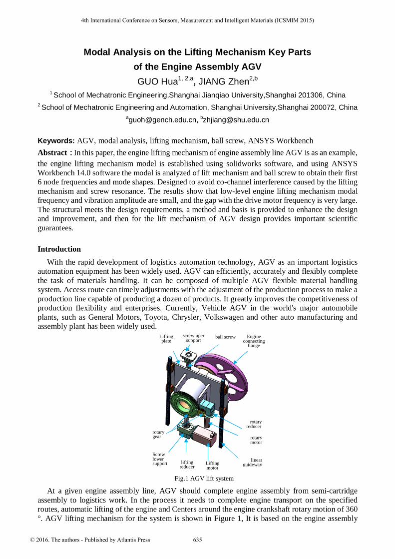
Fig.1 AGV lift system
At a given engine assembly line, AGV should complete engine assembly from semi-cartridge assembly to logistics work. In the process it needs to complete engine transport on the specified routes, automatic lifting of the engine and Centers around the engine crankshaft rotary motion of 360 °. AGV lifting mechanism for the system is shown in Figure 1, It is based on the engine assembly
rotary gear
Screw lower support
linear guideway
rotary reducer
Engine connecting
flange
ball screw screw uper support
Lifting plate
rotary motor
Lifting motor
lifting
reducer
4th International Conference on Sensors, Measurement and Intelligent Materials (ICSMIM 2015)
© 2016. The authors - Published by Atlantis Press 635
stations of different requirements. In this paper, Workbench ANSYS is used to analyze the mode of the connecting plate and the ball screw of the engine assembly line AGV. The aim is to find out the design of the problem in time, and then to optimize the structure.
The model establishment of the link plate and the ball screw lifting mechanism According to the AGV's work requirements, the structure is divided into four modules. The rack
mechanism, the forward drive mechanism, the engine lifting mechanism and the engine rotation mechanism. Frame part is mainly used steel welding. Forward drive module function steering wheel steering mechanism and the steering wheel are two options differential mechanism. We use four-wheel differential mechanism with two DC servo motors and gear to achieve differential steering. The engine lifting mechanism adopts the way of servo motor + ball screw and linear guide rail. The engine rotary mechanism adopts the servo motor and gear reducer mechanism.
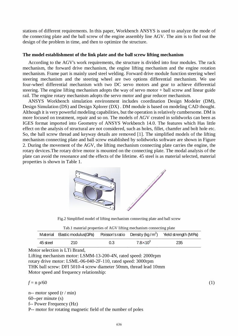
ANSYS Workbench simulation environment includes coordination Design Modeler (DM), Design Simulation (DS) and Design Xplorer (DX) . DM module is based on modeling CAD thought. Although it is very powerful modeling capabilities, but the operation is relatively cumbersome. DM is more focused on treatment, repair and so on. The models of AGV created in solidworks can been as IGES format imported into Geometry of ANSYS Workbench 14.0. The features which Has little effect on the analysis of structural are not considered, such as holes, fillet, chamfer and bolt hole etc. So, the ball screw thread and keyway details are removed [1]. The simplified models of the lifting mechanism connecting plate and ball screw established by solidworks software are shown in Figure 2. During the movement of the AGV, the lifting mechanism connecting plate carries the engine, the rotary devices.The rotary drive motor is mounted on the connecting plate. The modal analysis of the plate can avoid the resonance and the effects of the lifetime. 45 steel is as material selected, material properties is shown in Table 1.
Fig.2 Simplified model of lifting mechanism connecting plate and ball screw
Tab.1 material properties of AGV lifting mechanism connecting plate
Material Elastic modulus(GPa) Poisson's ratio Density (kg /m2) Yield strength (MPa)
45 steel 210 0.3 7.8 103 235
Motor selection is LTi Brand, Lifting mechanism motor: LSMM-13-200-4N, rated speed: 2000rpm rotary drive motor: LSML-06-040-2F-110, rated speed: 3000rpm THK ball screw: DFI 5010-4 screw diameter 50mm, thread lead 10mm Motor speed and frequency relationship:
f = n p/60 (1)
n-- motor speed (r / min) 60--per minute (s) f-- Power Frequency (Hz) P-- motor for rotating magnetic field of the number of poles
636
By the formula (1) shows the roughly proportional to the frequency and speed. Number of pole pairs P = 1, the speed of the rotating magnetic field n = 3000. Number of pole pairs P = 2:00, the speed of the rotating magnetic field n = 1500. Number of pole pairs P = 3, the speed of the rotating magnetic field n = 1000. Due to the presence of slip, the motor actual speed slightly below the speed of the rotating magnetic field actually.
China provides standard power frequency f = 50Hz, by type (1) it can be calculated that the natural frequency of the lift motor and the rotary motor is also 50Hz.
Modal Analysis of pre-treatment
The basic theory of modal analysis Modal analysis is an integral part of kinetic analysis. The main purpose is in order to determine the
machine parts or design agency natural frequencies and mode shapes. It is the vibration characteristics of the structure. In general, low-level vibration characteristics influence on the dynamic characteristics of the structure of the more obvious, and the dynamic characteristics of low order modes determine the structure [2].
One end of the link plate lifting mechanism connected to the engine via the flange. The lifting mechanism connecting plate and flange are connected by bolts, linear guide slider and the other end with the lifting mechanism are also connected by bolts. In addition, the lifting mechanism is equipped with motor and reducer connecting plate。When the natural frequency of a vibration frequency of the motor and the lifting mechanism of the connector plate are same, there will be a resonance phenomenon. And, severe vibration will make the machinery and equipment not working properly. The structure can be effectively verified by modal analysis. Modal Analysis of the lifting mechanism of the connector plate is an important part of its design, and the structural dynamic analysis of static test is the premise, too.
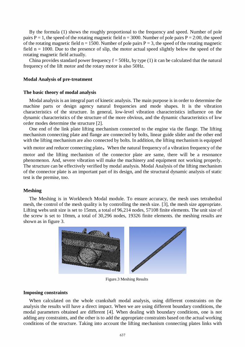
Meshing The Meshing is in Workbench Modal module. To ensure accuracy, the mesh uses tetrahedral
mesh, the control of the mesh quality is by controlling the mesh size. [3], the mesh size appropriate. Lifting webs unit size is set to 15mm, a total of 96,214 nodes, 57108 finite elements. The unit size of the screw is set to 10mm, a total of 30,296 nodes, 19326 finite elements. the meshing results are shown as in figure 3.
Figure.3 Meshing Results
Imposing constraints When calculated on the whole crankshaft modal analysis, using different constraints on the
analysis the results will have a direct impact. When we are using different boundary conditions, the modal parameters obtained are different [4]. When dealing with boundary conditions, one is not adding any constraints, and the other is to add the appropriate constraints based on the actual working conditions of the structure. Taking into account the lifting mechanism connecting plates links with
637
linear guide slider by bolts, the slider can move along the rail. The other directions are fixed with the guide rails. So we should apply the displacement constraint to the bolt hole in the calculation. In the middle at each end of the large hole have a bearing, the Compression constraint is applied, and the installation screw nut hole fixed constraint is imposed. The support of the ball screw is fixed at both ends, so the constraint imposed fixed at the ends.
The modal analysis and results Tab.2 The first six order modal analysis results
Lifting mechanism connecting plate
Node 1 2 3 4 5 6
[Hz] 973.14 1023.2 1057.2 1227.5 1244.6 1283.9
screw Node 1 2 3 4 5 6
[Hz] 189.97 190.24 525.65 526.24 1025.2 1026.1
In ANSYS Workbench software, the modal number programmed default to solve the first 6 modal
frequencies and mode shapes. Taking into account the low order modes influences on the dynamic characteristics of the structure greatly, so the first 6 results meet the requirements, without modification. As shown in Table 2, is the first 6 modal analysis results obtained. As can be seen from the table, the minimum frequency of the lifting mechanism connecting plate and the screw are quite different with the frequency of the motor, it will not affect the normal use of the mechanism.
Conclusions Modal finite element analysis is done on the lifting mechanism and the ball screw of the engine
assembly line AGV, the first 6 vibration frequencies and mode shapes are obtained. The more accurate results intuitive, avoids co-channel interference caused by the lifting mechanism and screw resonance. These analyzes have great effects on the design of the engine assembly line AGV and subsequent analysis check. The traditional modal problems are analyzed based on the ANSYS Workbench software, it can avoid the calculation method of transmission, provide a reference for the same type of structural design problems and improve the design efficiency.
Acknowledgements This work was financially supported by the Shanghai Natural Science Foundation (61433016)
References
[1] FU Zhong-yu,YANG Xiao-jing. Modal Analysis of Leading Screw Based on ANSYS
Software. Machine Building & Automation. 33, 37-39 (2004).
[2] Li Yaoming, Sun Pengpeng, Pang Jing, Xu Lizhang. Finite Element Modal Analysis and Experiment on the frame of Combine chassis. Transactions of the Chinese Society of Agricultural Engineering, 29, 38-42 (2013).
[3] Ling Guilong, Ding Jinbin, Wen Zheng. From the introduction to the master of ANSYS Workbench 13.0. BeiJing: Tsinghua university press (2012).
[4] LV Duan, ZENG Dong-jian, YU Xiao-yang, ZHANG Long-ping. Finite Element Modal Analysis of V8 Engine Crankshaft Based on ANSYS Workbench. Machinery Design & Manufacture, 08, 11-13 (2013).
638