Embed Size (px)
Citation preview

- 1 -
MODAF-M10-001
MINISTRY OF DEFENCE
MOD Architectural Framework
Customer 1 Community of Interest Deskbook
Issue 0.9
22 July 2005
Prepared by:-
Approved by:-
CROWN COPYRIGHT 2005.
THIS DOCUMENT IS THE PROPERTY OF HER BRITANNIC MAJESTY’S GOVERNMENT. This material (other than the Royal Arms and departmental or agency logos) may be reproduced free of charge in any format or medium provided it is reproduced accurately and not used in a misleading context. Where this material is being republished or copied to others, the source of the material must be identified and the copyright status acknowledged.
For further information on Crown Copyright policy and licensing arrangements, see the guidance featured on the HMSO website http://www.opsi.gov.uk

- 2 -
RECORD OF CHANGES
This page will be updated and re-issued with each amendment. It provides an authorisation for the amendment and a checklist to the current amendment number.
Issue No. Date Revision Details
Draft 0.1 20 Jan 2005 First Draft
Draft 0.2 31 Jan 2005 Revisions to balance Technical Volume and Deskbook
Draft 0.3 8 March 2005 Enhanced process mapping section
Draft 0.4 18 March 2005 Worked example included
Draft 0.5 30 March 2005 Revised Customer 1 process section included
Draft 0.6 31 March 2005 Updated Appendices A, B & C
Draft 0.7 5 April 2005 Updated following MODAF Partner Review
Draft 0.8 5 April 2005 Worked example expanded to URD stage
Draft 1.0 5 April 2005 Issued Draft Version
Draft 1.1 11 May 2005 Appendices removed, and content rationalised to reflect Customer 1 DEC Workshop & feedback comments
Draft 1.2 13 May 2005 Amendments following MODAF Partners Review
Draft 2.0 6 June 2005 Issued Draft Version
Draft 2.1 17 July 2005 Amendments following Deskbook Review board on 7th July 2005
Draft 2.2 20 July 2005 Amendment following internal review of revised draft
Issue 0.9 22 July 2005 Pre-MODAF Baseline Issue Version

- 3 -
Customer 1 MODAF Deskbook - Table of Contents
1. Foreword ........................................................................................................... 4
2. Introduction .......................................................................................................... 5 2.1 What is MODAF?.......................................................................................... 5 2.2 Guide to Deskbook ....................................................................................... 6
2.2.1 Purpose ................................................................................................. 6 2.2.2 Context .................................................................................................. 6 2.2.3 Deskbook Structure ............................................................................... 8
3. MODAF Relationship to Customer 1 Business Processes and Activities ............ 9 3.1 Architecture Development Process .............................................................. 9
3.1.1 Six-Stage Architecture Development Process....................................... 9 3.1.2 Architectural Data Sources.................................................................. 10 3.1.3 Application to Customer 1 Process ..................................................... 10 3.1.4 Overview of MODAF View use ............................................................ 10 3.1.5 Ensuring views are MODAF compliant - hybrid and modified views ... 11
3.2 Customer 1 Process ................................................................................... 12 3.2.1 Key to the Process / View Mapping Diagrams .................................... 13
3.3 Develop Capability Taxonomy .................................................................... 13 3.3.1 Decompose Vision Into Capability Taxonomy ..................................... 13
3.4 Conduct Capability Audit ............................................................................ 15 3.4.1 Gather Information For Capability Audit .............................................. 16 3.4.2 Analyse Data & Identify Capability Issues ........................................... 19 3.4.3 Schedule Capability Delivery............................................................... 20
3.5 Develop Options ......................................................................................... 21 3.5.1 Review Capability Submissions Across DEC & Customer 2 ............... 22 3.5.2 Develop Capability Options & BOI Studies.......................................... 24
3.6 Establish Equipment Programme ............................................................... 25 3.6.1 Report Preferred Capability Option(s) To JCB .................................... 26 3.6.2 Review Programmes & Expenditure.................................................... 26 3.6.3 Revise & Re-work Options .................................................................. 27 3.6.4 Decision Conference (JCB) ................................................................. 27 3.6.5 Articulating Capability Options Post EP Baseline................................ 27
3.7 Requirements Development ....................................................................... 29 3.7.1 Develop URD....................................................................................... 29 3.7.2 Beyond URD Baseline......................................................................... 31
4. Worked Example................................................................................................ 32 4.1 ISTAR Worked Example Introduction ......................................................... 32 4.2 Develop Capability Taxonomy .................................................................... 33 4.3 Conduct Capability Audit ............................................................................ 35
4.3.1 Gather Information For Capability Audit .............................................. 35 4.3.2 Analyse Data & Identify Capability Issues ........................................... 36
4.4 Develop Options ......................................................................................... 38 4.5 Establish Equipment Programme ............................................................... 42 4.6 Requirements Development ....................................................................... 42 4.7 Summary .................................................................................................... 51
5. Document Maintenance..................................................................................... 52
Appendix 1. MODAF View Mapping To Customer 1 Process ............................. 53

- 4 -
1. Foreword
(Generic foreword - championing the use of MODAF, covering mandation issues and policy, emphasis of the benefits of MODAF and an architectural approach – to be written by MOD)
- 5 -
2. Introduction
2.1 What is MODAF?
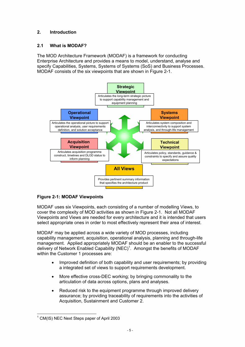
The MOD Architecture Framework (MODAF) is a framework for conducting Enterprise Architecture and provides a means to model, understand, analyse and specify Capabilities, Systems, Systems of Systems (SoS) and Business Processes. MODAF consists of the six viewpoints that are shown in Figure 2-1.
Figure 2-1: MODAF Viewpoints
MODAF uses six Viewpoints, each consisting of a number of modelling Views, to cover the complexity of MOD activities as shown in Figure 2-1. Not all MODAF Viewpoints and Views are needed for every architecture and it is intended that users select appropriate ones in order to most effectively represent their area of interest.
MODAF may be applied across a wide variety of MOD processes, including capability management, acquisition, operational analysis, planning and through-life management. Applied appropriately MODAF should be an enabler to the successful delivery of Network Enabled Capability (NEC)1. Amongst the benefits of MODAF within the Customer 1 processes are:
• Improved definition of both capability and user requirements; by providing a integrated set of views to support requirements development.
• More effective cross-DEC working; by bringing commonality to the articulation of data across options, plans and analyses.
• Reduced risk to the equipment programme through improved delivery assurance; by providing traceability of requirements into the activities of Acquisition, Sustainment and Customer 2.
1 CM(IS) NEC Next Steps paper of April 2003
SystemsViewpoint
Articulates system composition and interconnectivity to support system
analysis, and through-life management
Acquisition Viewpoint
Articulates acquisition programme construct, timelines and DLOD status to
inform planning
All Views
Provides pertinent summary information that specifies the architecture product
Strategic Viewpoint
Articulates the long-term strategic picture to support capability management and
equipment planning
TechnicalViewpoint
Articulates policy, standards, guidance & constraints to specify and assure quality
expectations
Operational Viewpoint
Articulates the operational picture to support operational analysis, user requirements
definition, and solution acceptance

- 6 -
2.2 Guide to Deskbook
2.2.1 Purpose
The purpose of this document is to • Assist relevant members of the Customer 1 community to produce MODAF
compliant architectures • Illustrate to the general Customer 1 community how the MODAF Views within
these architectures can support the various elements of their processes and activities.
2.2.2 Context
The Customer 1 Deskbook forms part of the overall suite of MODAF 1.0 baseline documentation as shown in Figure 2-2.
TaxonomyTaxonomy
Meta ModelMeta Model
MODAF Acronyms ListMODAF Acronyms List
COI COI DeskboDeskbo
okok
COI COI DeskboDeskbo
okok
Customer 1Customer 1DeskbookDeskbook
COI COI DeskboDeskbo
okok
COI COI DeskboDeskbo
okok
MODAFMODAFCOICOI
DeskbookDeskbook
MODAFMODAFTechnical Technical HandbookHandbook
MODAFMODAFOverviewOverview
MODAF Executive SummaryMODAF Executive Summary
ViewViewOverviewOverview
ViewViewOverviewOverview
MODAF Glossary of TermsMODAF Glossary of Terms
“Quick Start” GuidesGuide - Developing Architectures
Figure 2-2: MODAF 1.0 Baseline Products
The main elements of the MODAF baseline are:
• Executive Summary – provides a brief summary of the entire MODAF baseline
• MODAF Overview – describes what MODAF is, why it should be used and details the process for developing architectures
• MODAF Technical Handbook – provides details of the construction of MODAF views and their relationship to the MODAF meta model (M3). This is supported by:

- 7 -
- View Overview – a short summary of each view intended for quick reference by MOD users
- Meta Model – used to define the architectural objects that are permitted in MODAF views and their relationships with each other
- Taxonomy – provides the approved names and definitions for architectural objects to be used within the MOD’s architectures
• MODAF Deskbooks – describe how users within particular communities in the MOD are expected to utilise MODAF architectures to support their processes. Each of the Deskbooks has one or more “quick start guides” that provide an easy reference summary of the relationship of MODAF views to the community’s processes
For the purpose of describing the relationship of MODAF to MOD’s processes, five Communities of Interest (COIs) have been considered as shown below in Figure 2-3. Whilst these do not describe the whole of the MOD’s processes as described in the Business Management System (BMS), they do cover the core processes around acquisition and military operations.
C A D M
C A D M I T
DI
Concepts & Doctrine
CapabilityManagement
Operations
FundedOptions
Capability GapsFuture Op
Needs
Doctrine
Customer 1 Acquisition
Sustain
Customer 2
Concepts & Doctrine
Figure 2-3: Community of Interest Deskbook Scope
The high level scope of these COIs is:
• Concepts and Doctrine – the development of analytical concepts (e.g. Joint HLOC), applied concepts (e.g. Carrier Strike Concepts) and in-service doctrine, SOPs and TTPs
• Customer 1 – the monitoring of capability gaps against future needs, building the Equipment Programme (EP) and ownership of URDs for new capabilities
• Acquisition – the development and fielding of new military capabilities, the primary focus is up to the acceptance into service of a fully operational capability
• Sustain – the processes to maintain and upgrade a military capability throughout its operational life

- 8 -
• Customer 2 – the Front Line Commands planning and conducting their operational activities including their Core Leadership and Pivotal Management roles as defined in Smart Acquisition2
2.2.3 Deskbook Structure
The remainder of the MODAF Customer 1 Deskbook comprises two key sections:
Section 3 - MODAF’s Relationship to the Customer 1 Processes and Activities – this section explains the process of architecting as applied by those engaged in the Customer 1 processes. Specifically, it identifies the key activities in the capability management, equipment planning and URD development processes and outlines how these align with the MODAF Viewpoints.
Section 4 - Worked Example of MODAF in Customer 1 – this section demonstrates how MODAF can be used practically within Customer 1 by means of a real-life architecture example.
In addition, the following ‘quick start guides’ are available that summarise key elements of this Deskbook:
• Capability Management Guide
• User Requirements Document Guide
2 See Smart Acquisition Handbook, available on the Acquisition Management System (AMS) at http://www.ams.mod.uk

- 9 -
3. MODAF Relationship to Customer 1 Business Processes and Activities
3.1 Architecture Development Process
3.1.1 Six-Stage Architecture Development Process
The approach to developing a MODAF-compliant architecture is shown in Figure 3-1. This shows how a MODAF user within any community in the MOD goes about establishing the intended use, scope and data requirements, developing the architecture, using this to conduct the required analyses and documenting the results. A more detailed description of this six-stage architecture development process is provided in the Overview of MODAF (MODAF-M07-020).
Figure 3-1: General Process for Building MODAF-Compliant Architectures
In addition to showing the steps that a MODAF user should follow, Figure 3-1 also highlights the MODAF resources that are available to help them and the key interactions that are required with the MODAF governance processes. One of the key MODAF governance mechanisms is the MOD architectural repository (MODAR) that is run by the Integration Authority (IA). This can be used to run queries and extract existing architectural data – such as information on the systems that a new capability has to interface with. It is also important that all new architectures are lodged with MODAR to inform others and allow the re-use of new architectural data. Furthermore, for the Acquisition community the IA provides additional integration services that assist in modelling end-to-end performance and interoperability assurance.
Another key resource will be the list of certified tools. The MODAF tool certification scheme is still being developed at the time of this MODAF baseline issue, definitive
User training- MODAF principles
Prerequisites 1. Establish Intended
Use
2. Define Architecture
Scope
3. Develop Data
Requirements
4. Capture Architecture
5. Conduct Analyses
6. Document Results
MODAF Governance
MODAF Users
MODAF Resources
MODAF Baseline
Architectural Use Doc.
Workshop -Determine Architecture Usage
Workshop -Bound Architecture Scope
Workshop -Establish Data Needs
Architectural Scope Doc.
Tool Selection
Data Gathering Plan
BaselineArch. Review
Baseline Architecture
Inform Central Reg.
Query of Avail. Data Sources
Publish Baseline to MODAR
Tool-specific Training
Initial Analysis
Final Analysis
Analysis Review
Finalised Architecture
Finalised Arch. Review
Publish Final Arch. to MODAR
Provide Extant Arch.Data
MODAF Training Material
MODAF Tiger Teams
MODAF Tiger Teams
MODAF Help Desk
MODAF Help Desk
MODAF Help Desk
MODAF Help Desk
MODAF Help Desk
MODAF Help Desk
MODAF Tiger Teams
Certified Tool List
Tool Advice
Hybrid View Development
MODAF Tiger Teams
MODAF Tiger Teams
MODAF Tiger Teams
MODAF Taxonomy
ERM / M3
Workshop -Determine Use Cases
Plan of Time & Resources
- 10 -
guidance as to tool availability and fit with different COIs is not currently available. Therefore, interim guidance exists on the availability of MODAF convergent tools3.
In order to facilitate the searching and query of architectures it is essential that the All Views (AV-1 with meta data regarding the architecture and AV-2 with the architecture’s object dictionary) are completed thoroughly for all architectures before they are published.
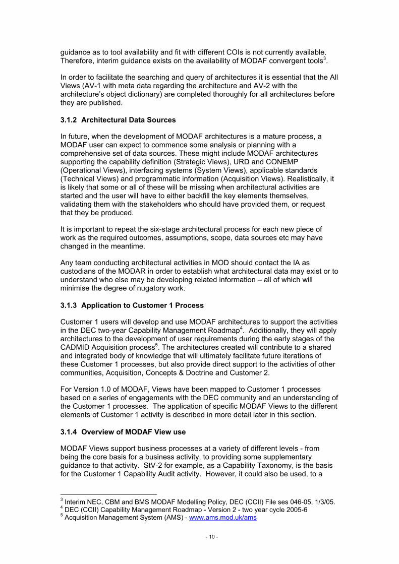
3.1.2 Architectural Data Sources
In future, when the development of MODAF architectures is a mature process, a MODAF user can expect to commence some analysis or planning with a comprehensive set of data sources. These might include MODAF architectures supporting the capability definition (Strategic Views), URD and CONEMP (Operational Views), interfacing systems (System Views), applicable standards (Technical Views) and programmatic information (Acquisition Views). Realistically, it is likely that some or all of these will be missing when architectural activities are started and the user will have to either backfill the key elements themselves, validating them with the stakeholders who should have provided them, or request that they be produced.
It is important to repeat the six-stage architectural process for each new piece of work as the required outcomes, assumptions, scope, data sources etc may have changed in the meantime.
Any team conducting architectural activities in MOD should contact the IA as custodians of the MODAR in order to establish what architectural data may exist or to understand who else may be developing related information – all of which will minimise the degree of nugatory work.
3.1.3 Application to Customer 1 Process
Customer 1 users will develop and use MODAF architectures to support the activities in the DEC two-year Capability Management Roadmap4. Additionally, they will apply architectures to the development of user requirements during the early stages of the CADMID Acquisition process5. The architectures created will contribute to a shared and integrated body of knowledge that will ultimately facilitate future iterations of these Customer 1 processes, but also provide direct support to the activities of other communities, Acquisition, Concepts & Doctrine and Customer 2.
For Version 1.0 of MODAF, Views have been mapped to Customer 1 processes based on a series of engagements with the DEC community and an understanding of the Customer 1 processes. The application of specific MODAF Views to the different elements of Customer 1 activity is described in more detail later in this section.
3.1.4 Overview of MODAF View use
MODAF Views support business processes at a variety of different levels - from being the core basis for a business activity, to providing some supplementary guidance to that activity. StV-2 for example, as a Capability Taxonomy, is the basis for the Customer 1 Capability Audit activity. However, it could also be used, to a
3 Interim NEC, CBM and BMS MODAF Modelling Policy, DEC (CCII) File ses 046-05, 1/3/05. 4 DEC (CCII) Capability Management Roadmap - Version 2 - two year cycle 2005-6 5 Acquisition Management System (AMS) - www.ams.mod.uk/ams

- 11 -
lesser degree, to inform the organisation structure of the sustainment community by providing a coherent and relevant structure on which to base, and potentially contract for, sustainment responsibilities.
MODAF Views may also provide a means of communication between different stakeholders in a process.
Two levels of use have been defined for MODAF Views identified in this Deskbook, reflecting the level of support provided by a View to a particular activity:
• Essential – Views that are essential for use during a particular Customer 1 activity·
• Highly Desirable – Views that are recommended to inform a particular activity, given that they contain a significant amount of data of value to that activity in the majority of scenarios or circumstances.
The Essential Views are the starting point for any new MODAF user. Highly Desirable Views are more appropriate to users who have more experience of MODAF and are looking for further ways of using architectural information to inform an activity.
Any View may be used in addition to the Essential and Highly Desirable Views at any stage if it helps in the execution of the analysis / task.
3.1.5 Ensuring views are MODAF compliant - hybrid and modified views
As identified in Figure 2-1, MODAF provides a discrete set of views that can be selected to model and visualise an architecture. However, it is possible for a user to create views that look similar to those specified by MODAF, but that are not compliant to MODAF, without understanding the data elements and relationships that MODAF specifies within the view construct.
In brief however, a view is considered MODAF compliant when the data elements and relationships within that view are the same as those specified by MODAF, in what is known as the meta-model. Reference the MODAF Overview6 and the Technical Handbook7. Otherwise, the view created is unlikely to be supported by the MODAR architectural repository, and other tools, and cannot claim MODAF compliance.
A ‘hybrid’ or ‘modified’ view is a MODAF compliant view that deviates in content from a view provided in the MODAF view suite (as described in the Technical Handbook7) but which still maintains compliance with the meta-model. Hybrid or modified views may contain a mixture of data elements from two or more views, or may only provide a subset of the information required for a fully compliant MODAF view.
For more information and guidance regarding MODAF compliance, readers should contact the MODAF project team or the IA.
6 MODAF Overview. Reference MOD-M09-002 7 MODAF Technical Handbook. Reference MOD-M07-022

- 12 -
3.2 Customer 1 Process
This Deskbook describes the architectural processes as they relate to the Customer 1 community by reference to the Customer 1 process model shown in Figure 3-2. This diagram also shows the key interfaces with the other communities considered within the MODAF Deskbooks.
CapabilityManagement
C A D M
C A D M I T
DI
Concepts & Doctrine
Operations
Customer 1
Capability Management
Develop Capability Taxonomy
Conduct Capability Audit
Develop Options
Establish Equipment Programme
EP URD
HLOC
Requirements Development
Feedback& Issues
Figure 3-2: Key Elements and Interfaces of Customer 1 COI Processes
The Customer 1 COI processes interface with all of the other COIs, except Sustainment. The key inputs and outputs are:
• Concepts and Doctrine – takes analytical concepts, including the High Level Operating Concept (HLOC), and translates them into capability requirements within the overall Capability Taxonomy, as the basis for driving the acquisition process.
• Acquisition – provides the Equipment Plan (EP), and subsequent User Requirements Documents (URD) that form the basis for acquiring capability.
• Customer 2 – receive feedback and issues from Customer 2 Core Leaders (CL) who provide input to Capability Management and Requirements Development processes through working groups, or as assigned Customer 2 leaders on aspects of the process.
The role of MODAF architectures in supporting the Customer 1 COI processes and its key interfaces with the other COIs is described in the sections that follow, structured according to the main sub-processes shown in Figure 3-2.
A complete one-page diagram of how the MODAF views map to Customer 1 processes is held in Appendix A.1. Each of the following sections refers to appropriate segments of that process to maintain clarity.

- 13 -
3.2.1 Key to the Process / View Mapping Diagrams
The key to the Process / View mapping diagrams in the following sections, and as shown in appendix A.1, is as follows:
• Activities are shown as unshaded rectangles with the name of the activity inside the rectangle
• MODAF Views are shown as inputs and ouputs:
− Essential MODAF Views are shown as rectangular objects, colour-coded by Viewpoint as shown in Figure 2-1
− Highly desirable MODAF Views are shown as ellipse objects, similarly colour-coded by Viewpoint as shown in Figure 2-1
3.3 Develop Capability Taxonomy
This section describes the use of MODAF in the Develop Capability Taxonomy process. The key activity that is helped by the use of MODAF is that of Decomposing the Capability Vision, namely the High Level Operating Concept (HLOC).
Figure 3-3 shows the key architectural products for Developing the Capability Taxonomy, and how this fits within the overall process, as previously shown in Figure 3-2.
Capability Management
Develop Capability Taxonomy
Conduct Capability Audit
Develop Options
Establish Equipment Programme
Requirements Development
StV-1 StV-2
CRD &CapabilityTaxonomy
Decompose VisionInto Capability
Taxonomy
Figure 3-3: Key MODAF Relationship to Develop Capability Taxonomy Activities
3.3.1 Decompose Vision Into Capability Taxonomy
The high-level capability vision is presented as an StV-1. This outlines the future capability requirements as a textual description. Figure 3-4 is an example of an StV-1. This will normally be provided to the Customer 1 Community as an input from the Doctrine and Operational Concepts Community (i.e. JDCC and single service doctrine branches). Refer to MODAF Concepts & Doctrine Deskbook8.
8 MODAF Concepts and Doctrine Deskbook. Reference: MODAF-M10-013

- 14 -
Figure 3-4: Example StV-1 Capability Vision
In order to specify clearly the capabilities required, the StV-1 Capability Vision is deconstructed into a set capability functions. The capability function decomposition, known as a Capability Taxonomy, is represented by MODAF in an StV-2 View.
The StV-2 Capability Taxonomy is structured hierarchically, sub-dividing each capability function into sub-capabilities and/or functions where necessary, to provide clarity and the necessary level of granularity to support subsequent processes. The terms used in the StV-2 should be expressed only in non-platform specific effects based terms.
In addition to the capability nomenclature, appropriate quantitative attributes and metrics for that specific capability or function should be included; e.g. the required speed of processing, the rate of advance, the maximum detection range, etc. The quantitative values attached to each capability can be expressed as being linked to a specific epoch, or be 'as-is' values or 'to-be' targets.
The process of capability function decomposition and the resultant StV-2 is shown in Figure 3-5 below. Figure 4-5 in the worked example provides an example of an StV-2 that includes capability metrics.
UNCLASSIFIED
THE JOINT HIGH LEVEL OPERATIONAL CONCEPT
CAPPING PAPER
CCII Elements
UNCLASSIFIED
THE JOINT HIGH LEVEL OPERATIONAL CONCEPT
CAPPING PAPER
CCII Elements
UNCLASSIFIED
THE JOINT HIGH LEVEL OPERATIONAL CONCEPT
CAPPING PAPER
CCII Elements
Capability Sub-capabilities1 2
C4 Integrated Command and Strategic (HQ) CBMBattlespace Management Operational (HQ) CBM(CBM) CBM of Tactical Land
ManoeuvreCBM of Tactical Maritime Component OperationsCBM of Tactical Air Component Operations
Global Information User CapabilitiesInfrastructure
Basic Infrastructure CapabilitiesInfrastructure Enabling CapabilitiesAir Traffic Control
Figure 3-5: Decomposition of StV-1 into StV-2 Capability Taxonomy
- 15 -
The StV-2 Capability Taxonomy can be used to show both the capability that currently exists, and that required in future epochs. This can be achieved by annotating a single StV-2 to identify which capability functions relate to either current or future requirements. Alternatively, two individual StV-2 architectures can be created, one to represent current capability, and one to represent future capability. New capability functions are integrated into the wider DEC Capability Taxonomy through a process of review and rationalisation of the capability required.
Note that the reference to ‘Capability’ in the MODAF views implies a full ‘military capability’; that which includes all Defence Lines of Development (DLoD). This is in contrast to the definition of ‘equipment capability’, which refers solely to the capability of equipments, systems or system of systems, ignoring the contribution of persons, organisations, processes etc. These definitions are reflected in the MODAF Glossary of Terms9.
The completed StV-2 can form the basis of a Capability Requirements Document (CRD). It is an expression of the capability functions agreed to be developed and deployed to fulfil, in part, the strategic capability vision.
The CRD, or the StV-2 Capability Taxonomy (in circumstances where a CRD is not produced), then provides the basis on which to carry out a Capability Audit. It also forms the basis for decomposing a set of user requirements later in the process, ensuring a close alignment between user need and the high-level capability vision.
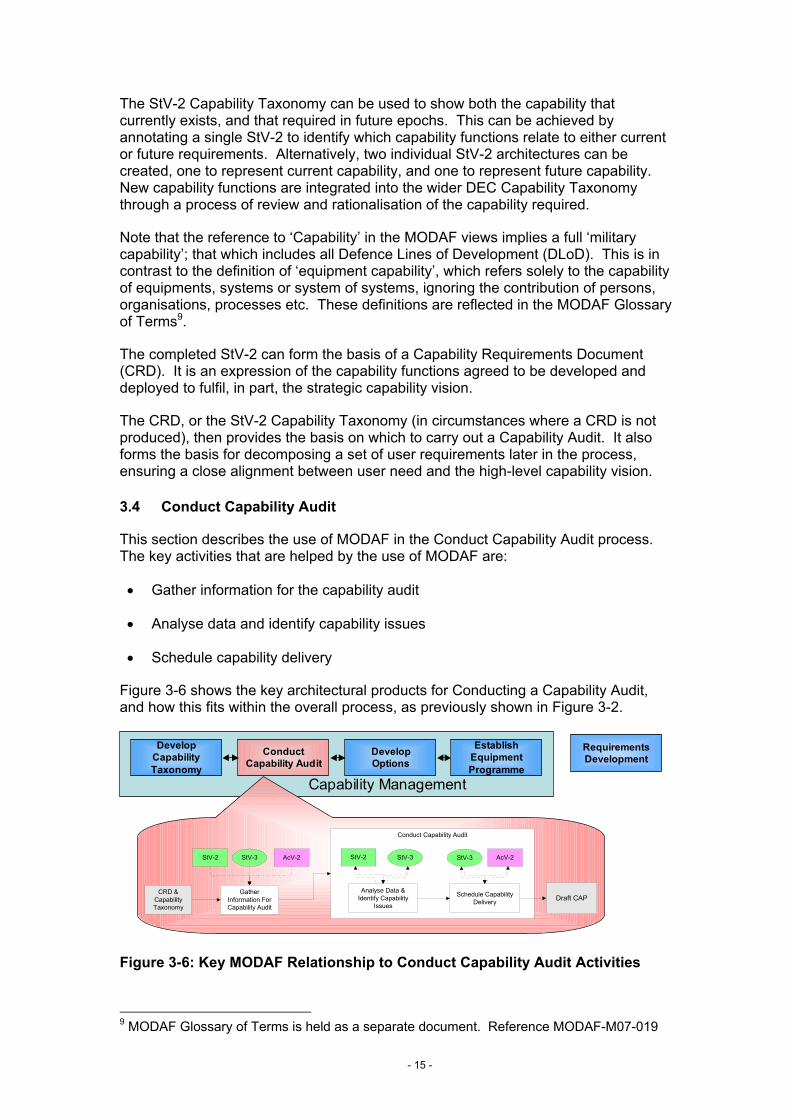
3.4 Conduct Capability Audit
This section describes the use of MODAF in the Conduct Capability Audit process. The key activities that are helped by the use of MODAF are:
• Gather information for the capability audit
• Analyse data and identify capability issues
• Schedule capability delivery
Figure 3-6 shows the key architectural products for Conducting a Capability Audit, and how this fits within the overall process, as previously shown in Figure 3-2.
Capability Management
Develop Capability Taxonomy
Conduct Capability Audit
Develop Options
Establish Equipment Programme
Requirements Development
Conduct Capability Audit
GatherInformation ForCapability Audit
CRD &CapabilityTaxonomy
AcV-2
Schedule CapabilityDelivery
Analyse Data &Identify Capability
Issues
StV-2StV-2 AcV-2StV-3 StV-3 StV-3
Draft CAP
Figure 3-6: Key MODAF Relationship to Conduct Capability Audit Activities
9 MODAF Glossary of Terms is held as a separate document. Reference MODAF-M07-019

- 16 -
3.4.1 Gather Information For Capability Audit
Before the Capability Audit process can begin, the relevant capability information is collated. Information required includes:
• The consolidated Capability Area Plan (CAP) – specific DEC CAPs submitted during the last cycle and any revised versions produced in the interim
• Programmatic data – status of programmes and projects that are planned within the DEC, those that are dependant on the DEC, those that are in-progress, or have been delivered since the last submission
• Updates to doctrine and strategic guidance – High Level Operating Concept (HLOC), Defence Planning Assumptions (DPAs), etc.
Some of this information is collected in the form of MODAF Views. Firstly, the StV-2 Capability Taxonomy is required, as the framework against which capability gap analysis can be performed in the Capability Audit. As previously shown in Figure 3-5, it is a structured articulation of the capability requirement.
It is then highly desirable to call upon (but not essential) the StV-3 Capability Phasing View, which shows the current capability delivery schedule. It supports the identification of capability shortfalls and capability surpluses, by epoch.
Examples of StV-3 are shown in Figure 3-7 and Figure 3-8. Figure 3-7 shows the DEC CCII Hybrid StV-3 that is collated before the Capability Audit – reference Section 3.1.5 on hybrid views. It utilises a sub-set of the potential data elements available to an StV-3, as it does not identify the systems that provide for a particular capability function. Instead, it shows a representative ‘level’ of available capability in a particular epoch using a measure of capability, and a Red, Amber, Green colour scheme.
StV-3 is underpinned by programmatic data that specifies when capability is being delivered, upgraded and withdrawn. This data should in the longer term be available from the MODAF repository, MODAR, populated by the Acquisition community. In the near term, it is collated and maintained by DEC liaison with the IPTs.
The capability decomposition in StV-3 is expressed in alignment with StV-2.
Note: MODAF defines ‘periods of time’, not epochs, in its viewpoints. Epoch is mentioned in this text due to its applicability to Customer 1. An StV-3 does not have to be structured in epochs, an appropriate period of time can be used.

- 17 -
Figure 3-7: DEC CCII Hybrid StV-3 Capability Phasing
Figure 3-8 shows a fully MODAF compliant StV-3. It utilises the full compliment of data elements, by additionally showing the systems that provide for each capability function in the capability taxonomy. It is created by mapping the systems to capability functions across relevant epochs; noting system delivery, upgrade and withdrawal. Each capability function is fulfilled by one or more systems, appropriate to specific epochs. The change in colour applied across the view reflects a change in capability level between two epochs - in a similar manner to that shown in the DEC Hybrid StV-3.
CAPABILITY FUNCTIONS Epoch 4 ( NEC enablers 2008-2012)
Decision SupportOp Planning JC2SS(F)/JTOC/ComBAT/ARRC C2IS
Operational Analysis JC2SS(F)/ComBAT?/ARRC C2IS?Mission Rehearsal JTOC IOC JTOC JTOC/ComBAT?/ARRCC2IS?Situational Awareness ComBAT/CID?/JC2SS/HVMSIFF/ARRC
C2IS/GBAD RAP IOC-FOC/ASTRID/T23 CEC/Gnd & Air BTIDS/INRTIBS
Intelligence
Joint Strategic Intelligence LOCE MIDB/LOCEOperational Intelligence INT-C/CTT INTELWEB?/MIDB/INRTIBS/CTTJoint Logisitcs JCS LogNATO C2 & Int NIDTS/NSWAN ACE ACCS Bi-SCAISNATO CommsLand US Coalition FBCB2?/MCS? FBCB2?/MCS?/ACBS?/MBCOTM?/FCS?/AMDWS?/ASAS?/CSSCS?Allied Interoperability MIP Messaging/US-GCCSMaritime RNCSS/LPD(R)/T22/T23/T42/CVS/T45Air C2/Coord
Functional Planning SupportInfo Ops Planning BSMSLogistic Planning AP3 Medical SGIS Medical BISA? Aviation Logistics Sp ACCESS Air Support BISA?Personnel Planning AP3/JCSLog G1 BISA?/JCS Log G1 BISA?/JCS Log/JC2SSEW Planning SOOTHSAYERAir Defence Planning AD BriC IGBAD IOCArtillery Fire Planning FCA FCBISA/IFPA JETTS IOC?Air PlanningEngineer/EOD PlanningCIS Planning GP3 GP3/BSAM GP3/ComBAT ComBATNBC BRACIS/BATES/BRACIS NT NBC BISA/BATES NBC BISAComms Management BCMS/CORMORANT CMSIS Management DBL II EOC DBL II IOC & FOC/DII(F)D Inc 2
NATO ADAllied Fire Support AFATDS-ASCA AFATDS II-ASCAMedical JPASS/In barracks Med
JOCS/ComBAT/GP3 (HQ ARRC only)/RAFCCIS/RNCSS/JC2SS(F)
JOCS (IPM only)/GP3(HQ ARRC only)/RNCSS/RAFCCIS/AMIR?
JOCS (IPM only)/GP3(HQ ARRC only)/RAFCCIS/RN CSS
JOCS (IPM only)/GP3(HQ ARRC only)/RAFCCIS/RN
ComBAT/GP3 (HQ ARRC only)/JOCS/RNCSS/HVM SIFF/GBAD RAP IOC/Gnd BTIDS/INRTIBS
CWAN (IPM only?)
JFAC-JPC/RAFCCIS/NICC/NIRS
BMETS/JOCS/GP3(HQ ARRC only)/RNCSS
BMETS/JOCS/BSAM/GP3(HQ ARRC only)/RNCSS/HVM/RAFCCIS SIFF/RAFCCIS/INRTIBS/JC2SS(C)/JPC/NIRS
Decision Support Interoperability
COMMAND BATTLESPACE MANAGEMENT
J2-G2 ISTAR BISA/AMIR
ADCIS
ASH
BATESAM BISA
Log C4 BISA/G1 BISA?
Epoch 2 (2004-2007)
JCS Log
JOCS/G2 BISA/GP3 (HQ ARRC only)/AMIR?/J2-G2 ISTAR BISA
ACCS LOC1
Epoch 3 (2006-2011)
MAKEFAST/EOD BISA
Epoch 1 (Now - 2008)
CRONOS (IPM only)
MIP Database/US-GCCS
FALCON CMS/BCMS/CORMORANT CMS
AP3/QP24
ATacCS/JOCS/RNCSS/RAFCCIS
WAH-64 GSS
Functional Planning Support Interoperability
ACCESS
RNCSS/LPD(R)/T22/T23/T42/CVSUS-GCCS (IPM only)
DACCS/JFAC-JC2SSJFAC-JPC/RAFCCIS/NICC/NIRS/JC2SS
JOCS (IPM only)/GP3(HQ ARRC only)/RNCSS/RAFCCIS
Figure 3-8: Example of a fully compliant StV-3 Capability Phasing
Finally, Acquisition View AcV-2 is collated to show when the acquisition programmes are expected to deliver scheduled capability, to support decision making during the Capability Audit and Equipment Planning activities. Examples of AcV-2 are shown in Figure 3-9 and Figure 3-10. Figure 3-9 shows the DEC CCII Hybrid AcV-2 collated before the Capability Audit. It is known as the Equipment Programme (EP) View. It utilises a sub set of the MODAF AcV-2 data elements, as it does not currently identify programme dependencies or programme status across DLoDs.

- 18 -
Figure 3-9: DEC CCII AcV-2 Equipment Programme View
Figure 3-10 shows a fully MODAF compliant AcV-2 that utilises the full compliment of data elements, additionally showing programme dependencies and status across all Defence Lines of Development (DLoDs) at each stage boundary.
AcV-2 EXAMPLE VIEW
FOC 01/01/06
People
Organisation
Sustainment
Equipment Training
Doctrine
LoDs
Pre-IG
IG to MG
MG to IOC
IOC to FOC
In Service
Disposal
2004 2005
System A
FOC 01/08/05IOC 01/04/05MG 01/10/04
System C
IOC 01/10/06IG 01/06/04 MG 01/01/05
System B
MG 01/11/04IG 01/05/04 IOC 01/06/04
System D
IOC 01/05/05MG 01/10/04
System E
2006
DISPOSAL 01/05/05 OUT OF SERVICE 01/01/05
Figure 3-10: Example AcV-2 SoS Acquisition Programmes
The dependencies shown on an AcV-2 represent a known dependency between two acquisition programmes. They do not represent the nature of the dependency or any level of granularity beyond the link between acquisition programmes. i.e. they do not represent dependencies between specific DLoDs as could be interpreted from Figure 3-10.

- 19 -
3.4.2 Analyse Data & Identify Capability Issues
When the relevant information has been collated, the Capability Audit process can begin. In this example, we will assume that a full Capability Audit is required, as similar processes can be applied to a partial Audit.
The aim of the Audit is to determine capability surpluses and shortfalls within the DEC, against the composite requirements defined by the Defence Strategic Plan, DPAs, HLOC, etc.
The primary View used is the StV-2 Capability Taxonomy, which comprehensively lists the capability functions required to fulfil the vision. The first step is to review the list and check for missing or excess capability requirements in the logical decomposition. A logical gap in the Capability Taxonomy is depicted in Figure 3-11.
Capability Sub-capabilities1 2
C4 Integrated Command and Strategic (HQ) CBMBattlespace Management Operational (HQ) CBM(CBM) CBM of Tactical Land
ManoeuvreCBM of Tactical Maritime Component OperationsCBM of Tactical Air Component Operations
Global Information User CapabilitiesInfrastructure
Basic Infrastructure CapabilitiesInfrastructure Enabling CapabilitiesAir Traffic Control
?????
Figure 3-11: StV-2 Depicting A Capability Gap
The StV-2 should be updated to reflect required capability, and it can then be analysed to confirm which capability functions are already deployed, and which are scheduled for delivery. Any capability functions not accounted for are highlighted as capability gaps, and are noted in the Capability Shortfall Catalogue.
StV-2 however, neglects to show capability delivery timing, and thereby omits to show further capability surpluses and shortfalls associated with particular epochs.
Here, the StV-3 Capability Phasing View can be used; it is highly desirable but not essential. It can be updated to reflect both the required capability functions in the Capability Taxonomy, and the representative level of capability associated with an epoch.
Figure 3-12: DEC CCII Hybrid StV-3 depicting a capability shortfall

- 20 -
Capability surpluses and shortfalls are identified in an StV-3 as changes in the colour code. In the DEC Hybrid StV-3, the colours highlight when the level of capability drops below, or rises above, a pre-defined threshold. Figure 3-12 highlights two capability shortfalls in 2014 as a red colour code, against Tactical Land CBM and Tactical Air CBM Capabilities.
In a fully compliant MODAF StV-3, the View also identifies the systems that provide for a capability – as Figure 3-8. In this instance, capability surpluses and shortfalls are then observed by the presence, or not, of systems in support of a capability function. The View clearly identifies system gaps and overlaps across epochs because systems are named within the View construct.
All further capability gaps identified from StV-3 are entered into the Capability Shortfall Catalogue.
At this point, the identification of either a shortfall or surplus can be used as the start point for a more in-depth analysis to confirm the existence and nature of the capability issue. This analysis is covered by the Concepts & Doctrine Deskbook10.
In brief, the analysis can be in the form of:
• Operational analysis – to confirm that the capability is truly an issue in an operational scenario or use case, to confirm to which scenarios or use cases that gap is applicable, and to expand on the detail of the operational scenarios to develop a case for the capability need
• Further capability analysis – to develop a greater understanding of the capability issue, to determine when it truly becomes a shortfall or surplus, and to understand the performance implications of ignoring the issue. In addition, whether, for example, re-deployment or upgrade of existing systems, rather than the procurement of something new, can fulfil the capability issue.
The analysis is supported by a range of MODAF views dependent upon the specific intent of the analysis. For the former analysis, this would include the MODAF Operational Viewpoint suite, and for the latter analysis, the Strategic Viewpoint suite. Specifically there are two additional Strategic Views, StV-4 Capability Clusters and StV-5 Capability to Systems Deployment Mapping that can be called upon. StV-4 highlights other capabilities impacted a surplus or shortfall, and StV-5 confirms deployment surpluses or shortfalls across organisational units.
3.4.3 Schedule Capability Delivery
Having identified capability surpluses and shortfalls and understood to a greater degree the implications across the organisation, the next step is to schedule capability delivery.
To achieve this, the planner firstly confirms the relative capability priorities (initially priorities are based on a local assessment to the DEC). In line with priorities, new capability delivery is scheduled into the overall DEC capability picture, and provides for the core body of the draft Capability Area Plan (CAP).
The process of scheduling capability delivery is informed by programme milestone, status and dependency information provided by the SoS Acquisition Programmes
10 MODAF Concepts and Doctrine Deskbook. Reference: MODAF-M10-013

- 21 -
AcV-2 View. The information detailed in this View informs and constrains the various capability schedule options.
Scheduled capability is presented on both the AcV-2 SoS Acquisition Programmes View and the Hybrid StV-3 Capability Phasing View, by updating them with the programme milestones and capability levels respectively. Annotation is used to identify the scheduled capability within the overall capability picture, as shown in Figure 3-13.
Figure 3-13: Hybrid AcV-2 and Hybrid StV-3 capability delivery schedule
The completed Hybrid Views AcV-2 and StV-3, along with other Views used during the capability audit process become part of the Capability Area Plan (CAP). The CAP provides a record of the activities carried out and an audit trail of the Capability Audit.
3.5 Develop Options
This section describes the use of MODAF in the Develop Options process. The key activities that are helped by the use of MODAF are:
• Review (CAP) submissions across DEC & Customer 2
• Develop capability options & Balance Of Investment (BOI) studies
Figure 3-14 shows the key architectural products for Developing an Option, and how this fits within the overall process, as previously shown in Figure 3-2.
Capability Management
Develop Capability Taxonomy
Conduct Capability Audit
Develop Options
Establish Equipment Programme
Requirements Development
Draft CAP Develop CapabilityOptions & BOI StudiesCAPReview Submissions
Across DEC & C2
AcV-2StV-3AcV-2StV-3
CapabilityOption
Figure 3-14: Key MODAF Relationship to Develop Options Activities

- 22 -
3.5.1 Review Capability Submissions Across DEC & Customer 2
When the Capability Audits have been completed in each of the individual DECs, the draft CAPs are brought together in the Capability Audit Workshop. The aim of the Capability Audit Workshop is to understand, confirm and rationalise the capability plans across the DECs.
It is during this stage that the benefit of MODAF as a common language is more apparent. Firstly, the capability propositions are presented with common MODAF Views, and as such, the draft CAPs can be more easily absorbed, compared and contrasted. Secondly, because consistency is provided by the MODAF data structure, revisions and/or combinations of the plans can be generated more quickly.
MODAF Views brought into this stage provide a source of constraints information, and a means to analyse and identify preferable delivery strategies. Constraints across the DEC-wide capability picture restrict the initial aspirations of the DEC draft CAPs. The types of constraint include:
• Feasibility – the need to ensure that the capability can be delivered, deployed, integrated and supported in the given timescales, budget and environment (environment noted in the widest sense – including external influences).
• Operational strategy – the need for alignment and coherence with cross-DEC strategies
• Business capacity – the need for the business to absorb the capability within existing capability picture, and within the portfolio of acquisition programmes.
The DEC CCII Hybrid AcV-2 SoS Acquisition Programmes is the primary View used to identify constraints. It presents feasibility constraints as the milestones of other acquisition programmes. The milestones of other programmes will inform the capability schedule and approach. This is shown in
Figure 3-15.
Figure 3-15: DEC CCII Hybrid AcV-2 highlighting milestone constraints
The fully compliant MODAF AcV-2 also highlights the status of dependent programmes across all Defence Lines of Development (DLoD). It then provides a

- 23 -
level of confidence as to the likelihood of delivering the proposed capability schedule on time. For example, consider that the status of an IT infrastructure programme is RED; the likelihood of timely delivery is low. With a set of four capability propositions, three dependent on the IT infrastructure programme, it may be advantageous to select the fourth option on the basis that timely delivery is more important than accepting a risk associated with late delivery.
Operational Strategy and Business Capacity Constraints can be identified by calling upon other MODAF views (refer to MODAF Viewpoint Overview document11 for details of other Views). For Operational Strategy Constraints, OV-1a can be used to identify dependencies on other military objects in a scenario, and factors associated with the battlespace physical environment. For Business Capacity Constraints, StV-5 Capability Deployment can be used to indicate, at a high level, the capacity of an organisation to absorb additional capability delivery.
Capability delivery strategy can be informed by the Hybrid StV-3 Capability Phasing View. Figure 3-16 shows how it can support the questioning or challenge of different strategies; namely, whether addressing the Tactical Land CBM capability is of greater importance than that of Tactical Air CBM, or whether both capability shortfalls could be addressed, but to a lesser degree.
Figure 3-16: DEC CCII Hybrid StV-3 informing a strategy decision
When using a fully compliant MODAF StV-3, the systems that provide for the capability enable greater strategy analysis. Discussions extend to whether system augmentation, or further fragmentation, across capability functions is the best strategy approach. For example, it may be worth decommissioning one system earlier than scheduled to align with the delivery of a new joint system that will provide for both this capability, and other capabilities.
The output of the capability workshop is a baseline CAP, presented as a refinement of the MODAF Views already created. StV-3 is produced to reflect a schedule of capability delivery that aligns with DEC-wide strategy, rather than as previously, the local DEC requirements.
11 MODAF Viewpoint Overview. Reference MODAF-M07-017
OR
?
?

- 24 -
3.5.2 Develop Capability Options & BOI Studies
The baseline CAPs feed into the first year of the two-year Equipment Programme (EP), and are reviewed against the spending commitments of the current equipment plan, and the forecast expenditure of the current acquisition programme portfolio.
At this stage, the Joint Capabilities Board (JCB) request that the individual DECs carry out Excursion and Balance Of Investment (BOI) studies to specify a realistic and affordable equipment programme. The DECs develop Capability Options as variations to the EP that may deliver more capability in specific areas, or deliver capability more swiftly or over a wider scope at less depth. The Capability Options must deliver the EP within the overall budget, bounded by Resource Control Targets (RCTs) set by the JCB.
This process currently involves the development, analysis and sifting of numerous capability options, culminating in 100+ capability options that are finally presented to the JCB, of which 6-12 may be selected to go forward. The options cover numerous capability domains and are compiled in very short timescales, based primarily on cost.
MODAF views cannot currently be used to articulate each capability option at this stage in the process because of the size, complexity and urgency of the task. They can only be used to support the identification of capability options. However, looking forward to the JCB decision conference, when a handful of capability options have been approved and baselined in the Equipment Plan (EP), it is possible to articulate options using MODAF views. This articulation adds value by informing Acquisition, Concepts & Doctrine and Customer 2 activity through the coming stages of CADMID, and by supporting the next EP cycle.
As such, the documented MODAF support to capability option development in the following sections comprises two parts, the high level use of MODAF views in the identification of capability options at this stage in the process (but similarly in section 3.6.3 where options are re-worked), and the suggested use of MODAF views to articulate each capability option post JCB Decision Conference, as presented in section 3.6.5.
Note: Where, in the future, the capability option development process at this stage changes in form - characterised by only a handful of co-ordinated options reaching the JCB for decision - then the mapping of MODAF views to this process should be reviewed. The suggested views for articulation of capability options described in section 3.6.5 can be taken as a start point.
The DEC Hybrid StV-3 Capability Phasing View is the basis for identifying a particular capability option; the three dimensions that form a capability option are shown in Figure 3-17.

- 25 -
Figure 3-17: Using DEC CCII Hybrid StV-3 to identify a Capability Option
Firstly, it identifies the capability taxonomy from which a reduced set of capability functions are selected to inform the first dimension of a particular option. Secondly, it shows the capability ‘levels’ that provide for each capability function (these would be shown as ‘systems’ on a fully MODAF compliant StV-3). Finally, it highlights the epochs over which the capability is delivered, as a third dimension to a capability option.
Figure 3-18 shows DEC CCII Hybrid AcV-2, which in a similar fashion, provides a means of identifying programme and milestone information that can be inserted into a particular capability option.
Figure 3-18: DEC Hybrid AcV-2 identifying the milestones appropriate to a capability option
3.6 Establish Equipment Programme
This section describes the use of MODAF in the Establish Equipment Programme process. The key activities that are helped by the use of MODAF are:
• Report preferred capability options to the JCB
• Review programmes & expenditure
• Revise & re-work options
• Decision conference (JCB)
• Articulating Capability Options post EP baseline Note: This activity is not forming part of the initial DEC implementation of MODAF and hence it does not form part of the Customer 1 process diagram at this time. It is however mentioned here in earnest, because of its potential benefits, and likely implementation at some point soon afterwards.

- 26 -
Figure 3-19 shows the key architectural products for Establishing an Equipment Programme, and how this fits within the overall process, as previously shown in Figure 3-2.
Capability Management
Develop Capability Taxonomy
Conduct Capability Audit
Develop Options
Establish Equipment Programme
Requirements Development
Report PreferredCapability Option(s)
(JCB)Updated CAPCapability
OptionReview Programmes
& ExpenditureDecision Conference
(JCB)Revise & Re-work
Options EPUpdated CAP
AcV-2StV-3
Figure 3-19: Key MODAF Relationship to Establish Equipment Programme Activities
3.6.1 Report Preferred Capability Option(s) To JCB
The capability options are collated and submitted to the Joint Capabilities Board (JCB) for prioritisation, and this forms the end of the first year of the two year EP cycle.
3.6.2 Review Programmes & Expenditure
In the beginning of the second year of the EP cycle, a process of acquisition programme review and investment priority agreement enable the capability options to be prioritised and finalised by the JCB.
If the capability option cost decomposition is expressed against capability functions in the integrated StV-2 Capability Taxonomy provided by MODAF, then direct comparisons of cost can be made across the Capability Options, and conclusions drawn more quickly. See Figure 3-20.
vs
vs
vs
vs
vs
Capability 1Capability 1.1
Capability 1.2
Capability 1.3
Capability 1.4
Capability 1.5
Capability 2Capability 2.1
Capability 2.2
Capability 2.3
Capability 2.4
Capability 1Capability 1.1
Capability 1.2
Capability 1.3
Capability 1.4
Capability 1.5
Capability 2Capability 2.1
Capability 2.2
Capability 2.3
Capability 2.4
£100k £500k
£1.1m £2m
£500k £0k
£600k £0k
£2.2m £2.5m
Option 1 Option 2
Figure 3-20: MODAF facilitating capability option comparison through commonality of capability language used from StV-2 Capability Taxonomy

- 27 -
Savings may extend from a specific combination of options between DECs, therefore enabling investment in further capability within the same epoch.
3.6.3 Revise & Re-work Options
With reference to the initial capability option development stage, MODAF Views StV-3 and AcV-2 are updated to reflect any changes extending from option development.
3.6.4 Decision Conference (JCB)
The JCB presents the preferred combination of capability options as a baseline Equipment Plan (EP) to the Defence Management Board (DMB) for endorsement.
A Decision Conference is undertaken to vote on the preferred capability options, and the majority preference is worked into the EP, forming a baseline version against which procurement activities can commence.
3.6.5 Articulating Capability Options Post EP Baseline Note: As mentioned above, this section is not forming part of the initial DEC implementation of MODAF but is mentioned here in earnest, because of its potential benefits, and likely implementation at some point soon afterwards.
The baseline of the Equipment Plan is a starting point for developing a set of MODAF Views to articulate the chosen capability options in this equipment round. MODAF recommends the following views to articulate a capability option.
• StV-3 and AcV-2, as used in capability option development – section 3.5.2
• Strategic View StV-5 Capability to Systems Deployment Mapping
• Operational Views OV-1a,b & c - the High Level Operational Graphic, its description and performance attributes respectively
Returning to the DEC Hybrid StV-3 Capability Phasing View,
Figure 3-21 shows how it can be annotated to articulate three dimensions of a Capability Option.
Figure 3-21: StV-3 indicating a Capability Option

- 28 -
Firstly, it highlights the capability taxonomy from which a reduced set of capability functions are selected to form the first dimension of a particular option. Secondly, it highlights the capability ‘levels’ that are characteristic of that capability option (or systems if the full MODAF compliant StV-3 was to be used). Finally, it highlights the epochs over which the capability is delivered as the third dimension to the capability option.
StV-3 can be supported by StV-5 to provide two additional dimensions in the specification of a capability option. It identifies, in addition to the dimensions of capability taxonomy, systems and epochs, the dimensions of organisational deployment and system interconnectivity.
An StV-5 specified capability option has a clear organisational scope, and a clear interconnectivity scope. Given that more complex interconnectivity requirements correlate with higher risks of implementation, the use of StV-5 is highly recommended in support of StV-3 for specification of a capability option.
Returning to AcV-2, Figure 3-22 shows how it can now be used to articulate a capability option as amended programme and milestone information annotated to the existing delivery picture.
Figure 3-22: Hybrid AcV-2 indicating a capability option
With a requirement to graphically articulate the capability option, its interfaces and the environmental context to which the capability will be deployed, OV-1a is a highly effective mechanism. The flexibility of the OV-1a High Level Operational Graphic enables a capability option to be depicted with all of its key interfaces. See worked example section 4.4 for an example of capability options shown as OV-1a. OV-1b is a textual description of OV-1a, and must be produced with every OV-1a created. OV-1c supports the OV-1a by listing the performance metrics associated with it. These can be drawn from the StV-2 Capability Taxonomy where available.

- 29 -
3.7 Requirements Development
This section describes the use of MODAF in the Requirements Development process. The key activity that is helped by the use of MODAF is Develop URD. This section also highlights, in summary, the activities beyond the baseline of the URD.
Figure 3-23 shows the proposed key architectural products for Requirements Development, and how this fits within the overall process, as previously shown in Figure 3-2.
Note: at the time of issue of this Deskbook, the proposed MODAF views and URD development sequence were not approved by the designated MOD URD process owner. They were suggested from consensus of opinion. Formal approval is expected in the next version.
Capability Management
Develop Capability Taxonomy
Conduct Capability Audit
Develop Options
Establish Equipment Programme
Requirements Development
EP
Operational View Suite
Develop URD
TV-1
URD
OV-1 OV-2 OV-3StV-6 OV-5URD Development SequenceTV-1OV-1 OV-2 OV-3StV-6 OV-5
-E R -E -
HDE E HDE HD
EE E EE E
Pre Concept
Initial Gate (IG)
Main Gate (MG)
Figure 3-23: Key MODAF Relationship to Requirements Development Activities
3.7.1 Develop URD
The finalised EP is used as a basis for the selection and grouping of acquisition programmes. For these programmes, user requirement sets are developed and maintained throughout the acquisition process.
The User Requirements Document (URD) is developed to specify the user needs, linking them back to the Capability Taxonomy, or CRD. The linkage between URD and CRD is not necessarily a one-to-one mapping; a capability function may be satisfied by more than one acquisition programme and URD.
MODAF supports the URD with a key set of Views to articulate the user requirements. Visual representations are used to strengthen textual requirements, providing a means of clarifying the complex issues involved.
The Views supporting each URD are based on the analysis of operational scenarios and vignettes extending from the SAG scenarios. MODAF provides StV-6 to specify the links between the Capability, and the Operational scenarios and vignettes. It also provides a suite of Operational Views to articulate the detail of each scenario or vignette.
Note that each of the operational scenario and vignettes contained in the URD should comprise the same set of operational Views, so as to retain the ability to compare and contrast Views with each other.

- 30 -
The development of the URD is progressive during the Concept and Assessment phases of the CADMID acquisition cycle. As such, MODAF Views are applied in a progressive manner over these phases to reflect this approach to its development. This is shown in Figure 3-24; Essential MODAF Views are shown as rectangular objects, and Highly Desirable Views as ellipse objects at each step of the cycle.
For further examples, please refer to the Worked Example Section 4.6 - Operational View suites.
IG MG
TV-1
OV-2
OV-1
OV-3
OV-5
Operational Viewpoint Suite
StV-6
OV-1
Operational Viewpoint Suite
OV-2
OV-1
Operational Viewpoint Suite
OV-5
TV-1
OV-3
OV-2
Assessment DemonstrationConcept
Scenario/ Vignette 1
Scenario/ Vignette N…
StV-6 StV-6
Figure 3-24: URD MODAF Views through CADMID
Approaching the process in steps, firstly consider pre-concept. An StV-6 is created to provide a framework for the URD scenarios and vignettes. Scenarios are articulated as a whole StV-6, which identifies a set of capability functions and operational activities. Vignettes are identified as an annotated sub-set of capability functions and operational activities within a scenario.
A generic StV-6 shown in Figure 3-25 shows how to articulate a vignette comprising Activities 5, 9, 10 and 12, and Capability 2 as part of a scenario.
Capability 1 Capability 2 Capability 3 Capability 4 Capability 5
Activity 1
Activity 2
Activity 3
Activity 4
Activity 5
Activity 6
Activity 7
Activity 8
Activity 9
Activity 10
Activity 11
Activity 12
Activity 13
Activity 14
Activity 15
X
X
X
X
XX
X
X
XX
XX
XX
X
X
X
Articulating a vignette: A set of operational activities to demonstrate Capability 2
Figure 3-25: StV-6 articulating a vignette, within a scenario
With StV-6 produced, the next step is to develop the suite of Operational Views. One suite is created for each scenario and vignette. For the Initial Gate, the suites must comprise OV-1 and OV-2 as follows.
• OV-1, and its constituent components, specifies the set of business objects and interconnectivity required and highlights the contextual battlespace

- 31 -
environment for a scenario or vignette. The High Level Operational Graphic, OV-1a, must be supported by OV-1b, its description. OV-1c lists the required operational performance attributes as a list of quantified measures
• OV-2 Operational Node Connectivity Diagram specifies the required set of operational nodes, connectivity and need line information flows for the scenario or vignette. This View ensures that the supplier is aware of the operational communications and interdependencies that will underpin the success of the solution.
For the Main Gate, OV-3 and OV-5 must form part of the suite:
• OV-3 Operational Information Exchange Matrix specifies the information exchanges to be satisfied by the solution. This View ensures that the supplier knows the precise detail, direction and content of the information flows that are part of a scenario or vignette, underpinning the design of the solution. When defining future information flow requirements is critical to take into account what actually happens at present, rather what is supposed to happen at present.
• OV-5 Operational Activity Model specifies the required set of operational activities utilised in the scenario or vignette. This View ensures that user activities are visible to the supplier and highlights the dynamic nature of operational staff roles. When defining future activity requirements is critical to take into account what is the actually happens at present, rather what is supposed to happen at present.
In addition to the Operational View suite, the Technical View is created for Main Gate to define the quality expectations and standards required of the solution. TV-1 can be created for individual vignettes, or be singular to the whole URD View Suite:
• TV-1 specifies the policies and standards that constrain the operational capability – including the interface standards and data format required to achieve interoperability.
The Essential architecture supporting the URD at Main Gate is now complete. However, note that other Views may be beneficial to particular scenarios or vignettes where there is a specific need. For example, System Views can be used to highlight and define the deployed Systems requiring interconnectivity. Refer to Appendix A, MODAF View Summary for further information.
3.7.2 Beyond URD Baseline
Following the baseline of the URD, the IPT appointed by DPA, DLO or DCSA takes control of solution development, manufacture, and ultimately delivery to Customer 2.
Customer 1, as owners of the URD and with responsibility for capability delivery, are involved by IPT throughout the stages of the CADMID cycle to assure progress and accept the solution against the user requirements expressed in the URD by MODAF Views. The URD is under change control and requests for change can be raised as required, and reviewed by the designated authority. Refer to Acquisition Management System (AMS)12 for further details on maintenance of the URD.
12 Acquisition Management System (AMS) - www.ams.mod.uk/ams

- 32 -
4. Worked Example
This section presents a worked example of MODAF View development in the Customer 1 community. It adds clarity, and realism, to the overview of the MODAF View relationship to Customer 1 processes provided in the previous section.
The example illustrated is based in the ISTAR community, and its level of complexity is simplified in order to avoid the need to understand specific ISTAR systems and technologies. The example does not represent the UK's ISTAR assets, it contains a number of fictional systems and entities.
A similar ISTAR example has been replicated in each of the COI Deskbooks to provide a common thread of understanding across business functions and processes. This approach has been selected to demonstrate MODAF's ability to integrate people, processes, organisations, systems and equipments across the MOD.
4.1 ISTAR Worked Example Introduction
The example covers the two-year EP cycle from the View of the ISTAR DEC. As in each of the DEC areas, systems are due into, and out of, service; in addition, doctrinal changes and revisions produce changes and subsequent enhancements to the Capability that must be delivered. Throughout this example, the process of the development and use of MODAF Views is covered in a greater level of detail than the associated EP processes, with which it is assumed that the audience is familiar.
The 'as-is' ISTAR situation is shown in an OV-1a, as Figure 4-1. OV-1a is always supported by an OV-1b, its description, as provided in Figure 4-2.
Figure 4-1: ISTAR 'As-is' OV-1a View

- 33 -
ISTAR information is currently provided by the SPECS system, the LOOKER UAV system and by the NEMESIS system. SPECS is an Operational level asset, and communicates via a data link to its dedicated base station. LOOKER is a tactical UAV system that can transmit real-time video footage directly to either Fighting Patrols or to the Brigade HQ. NEMESIS is a strategic asset that has considerable on-board processing capability, enabling the data to be exploited during flight. The resultant information can be communicated either by Satellite communications or directly to a receiver based on board a Naval vessel
Figure 4-2: ISTAR 'As-is' OV-1b View
LOOKER and SPECS are both mature systems with run-out dates in the near future. NEMESIS has just entered service and has an envisaged run-out date of 2035.
4.2 Develop Capability Taxonomy
The first step of the Capability Audit process is to decompose the Strategic Vision into a Capability Taxonomy. The Strategic Vision, in this case the HLOC, is represented as an StV-1 Capability Vision View. The relevant extract to DEC ISTAR is shown in Figure 4-3.
UNCLASSIFIED
THE JOINT HIGH LEVEL OPERATIONAL CONCEPT
CAPPING PAPER
…
8. The likelihood of increased involvement in low to medium intensity scenarios when the use of conventional reconnaissance forces is not possible, highlights the requirement to enhance our ability to acquire Beyond Line of Sight ISTAR information, without the need to deploy significant levels of Ground Forces.
…
11. Data fusion is a key enabler to the effective use of information. Collection, fusion and dissemination of data must be carried out in as near to real-time as possible in order to maximise the value of the information gained, and to minimise inaccuracy.
… Figure 4-3: StV-1 Capability Vision – Example HLOC
The HLOC has been revised since the last EP round, and in accordance with the associated doctrine updates, highlights the requirement for increased tactical levels of ISTAR provision and the need for near real-time data collection and fusion. This Capability Vision is now decomposed into a Capability Taxonomy, represented in the

- 34 -
StV-2 Capability Functions View. The StV-2 that was developed during the previous audit is used as the basis for development of the revised StV-2.
Figure 4-4 shows the process of decomposition, and Figure 4-5 shows the resultant StV-2, including the associated parameters and metrics for each of the Capability functions.
UNCLASSIFIED
THE JOINT HIGH LEVEL OPERATIONAL CONCEPT
CAPPING PAPER
…
8. The likelihood of increased involvement in low to medium intensity scenarios when the use of conventional reconnaissance forces is not possible, highlights the requirement to enhance our ability to acquire Beyond Line of Sight ISTAR information, without the need to deploy significant levels of Ground Forces.
…
11. Data fusion is a key enabler to the effective use of information. Collection, fusion and dissemination of data must be carried out in as near to real-time as possible in order to maximise the value of the information gained, and to minimise inaccuracy.
…
Information Acquisition
Information Management
Effects
1. Strategic
Range: 120km -1000kmDuration: 24hrs
1. Analysis 1. Targeting
Accuracy: 10m
2. Operational
Range: 20km - 120kmDuration: 20hrs
2. Fusion 2. Plan Engagement
3. Tactical
Range: 0km - 20kmDuration: 16hrs
3. Quality Assurance 3. Conduct Engagement
4. Dissemination 4. Battle Damage Assessment
Information AcquisitionInformation AcquisitionInformation Acquisition
Information ManagementInformation
ManagementInformation
ManagementEffectsEffectsEffects
1. Strategic
Range: 120km -1000kmDuration: 24hrs
1. Strategic
Range: 120km -1000kmDuration: 24hrs
1. Analysis1. Analysis 1. Targeting
Accuracy: 10m
1. Targeting
Accuracy: 10m
2. Operational
Range: 20km - 120kmDuration: 20hrs
2. Operational
Range: 20km - 120kmDuration: 20hrs
2. Fusion2. Fusion 2. Plan Engagement2. Plan Engagement
3. Tactical
Range: 0km - 20kmDuration: 16hrs
3. Tactical
Range: 0km - 20kmDuration: 16hrs
3. Quality Assurance3. Quality Assurance 3. Conduct Engagement3. Conduct Engagement
4. Dissemination4. Dissemination 4. Battle Damage Assessment4. Battle Damage Assessment
Figure 4-4: Decomposing StV-1 ISTAR HLOC into Capability Functions
Information Acquisition
Information Management Effects
1. Strategic
Range: 120km - 1000km
Duration: 24hrs
1. Analysis
1. Targeting
Accuracy: 10m
2. Operational
Range: 20km - 120km
Duration: 20hrs
2. Fusion
2. Plan Engagement
3. Tactical
Range: 0km - 20km
Duration: 16hrs
3. Quality Assurance
3. Conduct Engagement
4. Dissemination
4. Battle Damage Assessment
Figure 4-5: ISTAR StV-2 Parameters and Metrics
Please note that for the purposes of this example, only a reduced set of Capability functions within the ISTAR domain are included.

- 35 -
4.3 Conduct Capability Audit
4.3.1 Gather Information For Capability Audit
Firstly, relevant information and updates are gathered and collated. In this example the key information sources required are as follows:
• The latest version of the ISTAR DEC Capability Area Plan (CAP)
• The set of MODAF Views developed during the last Capability Audit and subsequent Option development
• Relevant Doctrine and Concepts revisions and updates.
In addition to the information gathered from the Customer 1 and Doctrinal domains, it is essential that programmatic information on current ISTAR systems, related dependant systems and other ongoing procurement activity is included. This is displayed in the form of an AcV-2 View, as shown in Figure 4-6.
ISTAR SYSTEMS
SPECS
DISP START
LOOKER
DISP START DISP FIN
NEMESIS
DISP START
People
Organisation
Sustainment
Equipment Training
Doctrine
LoDs
Pre-IG
IG to MG
MG to IOC
IOC to FOC
In Service
Disposal
Key to View
Project Phase
No outstanding issues
Manageable issues
Critical issues
LoD 'Hexagon'
2005 2020 2040
DISP FIN
Figure 4-6: ISTAR AcV-2 SoS Acquisition Programme
In this example, the run-out dates of LOOKER and SPECS are confirmed as falling at the end of Epoch 1 (date range set by the ISTAR DEC). In addition, the DPA have received a proposal for the manufacturer of SPECS, that it is possible to enhance the functionality of the system and hence prolong its in-service life.

- 36 -
4.3.2 Analyse Data & Identify Capability Issues
The next stage of the audit is to map the required capability functions to the systems that deliver or will deliver the capability. This is achieved initially using both the StV-2 Capability Functions View and the StV-3 Capability Phasing View. The StV-2 View provides the taxonomy for the required capability to be delivered. Systems can then be 'mapped' and 'phased' against the Capability Functions, in the StV-3 View. This mapping is shown in Figure 4-6.
Capability Functions
Epoch 1 Epoch 2 Epoch 3
Information Acquisition
Strategic NEMESIS NEMESIS
Operational SPECS
Tactical LOOKER
Information Management
Analysis NEMESIS NEMESIS
Fusion NEMESIS NEMESIS
Quality Assurance
NEMESIS NEMESIS
Dissemination BOWMAN, SAT BOWMAN, SAT
Effects
Targeting LOOKER, SPECS
Plan Engagement
BISA BISA
Conduct Engagement
CR2, MILAN, FGA
CR2, FGA CR2, FGA
BDA FGA, SAT FGA, SAT FGA, SAT
Capability FunctionsCapability FunctionsCapability Functions
Epoch 1Epoch 1Epoch 1 Epoch 2Epoch 2Epoch 2 Epoch 3Epoch 3Epoch 3
Information AcquisitionInformation Acquisition
StrategicStrategic NEMESISNEMESISNEMESIS NEMESISNEMESISNEMESIS
OperationalOperational SPECSSPECSSPECS
TacticalTactical LOOKERLOOKERLOOKER
Information ManagementInformation Management
AnalysisAnalysis NEMESISNEMESISNEMESIS NEMESISNEMESISNEMESIS
FusionFusion NEMESISNEMESISNEMESIS NEMESISNEMESISNEMESIS
Quality AssuranceQuality Assurance
NEMESISNEMESISNEMESIS NEMESISNEMESISNEMESIS
DisseminationDissemination BOWMAN, SATBOWMAN, SATBOWMAN, SAT BOWMAN, SATBOWMAN, SATBOWMAN, SAT
EffectsEffects
TargetingTargeting LOOKER, SPECS
LOOKER, SPECS
LOOKER, SPECS
Plan EngagementPlan Engagement
BISABISABISA BISABISABISA
Conduct EngagementConduct Engagement
CR2, MILAN, FGA
CR2, MILAN, FGA
CR2, MILAN, FGA
CR2, FGACR2, FGACR2, FGA CR2, FGACR2, FGACR2, FGA
BDABDA FGA, SATFGA, SATFGA, SAT FGA, SATFGA, SATFGA, SAT FGA, SATFGA, SATFGA, SAT
Information Acquisition
Information Management
Effects
1. Strategic
Range: 120km -1000kmDuration: 24hrs
1. Analysis 1. Targeting
Accuracy: 10m
2. Operational
Range: 20km -120kmDuration: 20hrs
2. Fusion 2. Plan Engagement
3. Tactical
Range: 0km -20kmDuration: 16hrs
3. Quality Assurance
3. Conduct Engagement
4. Dissemination 4. Battle Damage Assessment
Information AcquisitionInformation AcquisitionInformation Acquisition
Information ManagementInformation ManagementInformation Management
EffectsEffectsEffects
1. Strategic
Range: 120km -1000kmDuration: 24hrs
1. Strategic
Range: 120km -1000kmDuration: 24hrs
1. Analysis1. Analysis 1. Targeting
Accuracy: 10m
1. Targeting
Accuracy: 10m
2. Operational
Range: 20km -120kmDuration: 20hrs
2. Operational
Range: 20km -120kmDuration: 20hrs
2. Fusion2. Fusion 2. Plan Engagement2. Plan Engagement
3. Tactical
Range: 0km -20kmDuration: 16hrs
3. Tactical
Range: 0km -20kmDuration: 16hrs
3. Quality Assurance3. Quality Assurance
3. Conduct Engagement3. Conduct Engagement
4. Dissemination4. Dissemination 4. Battle Damage Assessment4. Battle Damage Assessment
Figure 4-7: Creating & analysing ISTAR StV-3 Capability Phasing
The StV-3 View shows that there will be gaps in Capability in the Operational and Tactical Information Acquisition areas (ISTAR) from Epoch 2 onwards. In addition, the Analysis, Fusion and Quality Assurance functions are only being provided by NEMESIS. Although there is no specific gap, this solution does not satisfy the objectives set out in the StV-1 Capability Vision for real-time data fusion.
The combined use of the StV-1, 2, and 3 Views has identified a Capability shortfall, namely the timely fusion and dissemination of ISTAR information, and a Capability gap, in the lack of Operational and Tactical ISTAR assets from Epoch 2 onwards.
Further analysis can now be carried out to confirm the findings, and understand the nature of the capability issue. StV-4 Capability Clusters and StV-5 Capability Deployment Mapping are used to achieve this.
Figure 4-8 shows the StV-4. It highlights that a reduced capability in Operational Information Acquisition might impact on the current capability in Effects, namely targeting and engagement planning, and also on information fusion. It similarly highlights that a reduced capability in Tactical Information Acquisition might impact on the engagement capability itself.

- 37 -
Information Management Effects
Information Acquisition
Strategic Operational
Tactical
Analysis
Fusion
Quality Assurance
Dissemination
Targeting
Plan Engagement
ConductEngagement
Battle DamageAssessment
Figure 4-8: StV-4 identifying capability dependencies
Figure 4-9 shows the StV-5, depicting system deployment across organisations over the three epochs being considered. It shows SPECS and LOOKER going out-of-service, leaving Capability gaps in Information Acquisition in Epoch 2. But more specifically, that the decommissioning of SPECS results in a capability gap for organisations PJHQ and JFQ, and that the decommissioning of LOOKER results in a capability gap for organisations Tactical – Brigade and Tactical - Special Forces.
Figure 4-9: ISTAR StV-5 Capability to Systems Deployment Matrix

- 38 -
4.4 Develop Options
Now that the Capability gaps and shortfalls have been confirmed, potential options are analysed to inform the Equipment Programme (EP).
Two Capability Options are identified to overcome the capability shortfall that results from the disposal of both SPECS and LOOKER at end of Epoch 1. Option 1 is defined in OV-1a and Ov-1b, as shown in Figure 4-10 and Figure 4-11.
Note: the articulation of an option using an OV-1 is a recommended way of articulating a capability option post EP-baseline, rather than at this point in the process (refer to section 3.6.5, with linkage to section 3.5.2). For the purposes of understanding the worked example however, the OV-1 is incorporated here.
Figure 4-10: ISTAR OV-1a Capability Option 1 – SPECS 2
Option 1: the LOOKER system has been replaced with KESTREL, a smaller system that would plan to deploy at least three UAV's for every one LOOKER system. SPECS has been upgraded to SPECS 2, and a Common ISTAR Base Station has been brought into service to enable data fusion between all ISTAR assets.
Figure 4-11: ISTAR OV-1b Capability Option 1 – SPECS 2

- 39 -
Figure 4-12 shows an updated fully compliant StV-3 for Option 1 (Highly Desirable), and Figure 4-13 the compliant AcV-2 (Essential).
Capability Functions Epoch 1 Epoch 2 Epoch 3
Information Acquisition
Strategic ISTAR NEMESIS NEMESIS
Operational ISTAR SPECS SPECS 2 SPECS 2
Tactical ISTAR LOOKER KESTREL KESTREL
Information Management
Analysis NEMESIS NEMESISISTAR GND
ISTAR GND
Fusion NEMESIS NEMESISISTAR GND
ISTAR GND
Quality Assurance NEMESIS NEMESISISTAR GND
ISTAR GND
Dissemination BOWMAN, SAT BOWMAN, SAT
Effects
Targeting LOOKER, SPECS KESTREL, SPECS 2
KESTREL, SPECS 2
Plan Engagement BISA BISA
Conduct Engagement CR2, MILAN, FGA CR2, FGA CR2, FGA
BDA FGA, SAT FGA, SAT FGA, SAT
Capability FunctionsCapability FunctionsCapability Functions Epoch 1Epoch 1Epoch 1 Epoch 2Epoch 2Epoch 2 Epoch 3Epoch 3Epoch 3
Information AcquisitionInformation Acquisition
Strategic ISTARStrategic ISTAR NEMESISNEMESISNEMESIS NEMESISNEMESISNEMESIS
Operational ISTAROperational ISTAR SPECSSPECSSPECS SPECS 2SPECS 2SPECS 2 SPECS 2SPECS 2SPECS 2
Tactical ISTARTactical ISTAR LOOKERLOOKERLOOKER KESTRELKESTRELKESTREL KESTRELKESTRELKESTREL
Information ManagementInformation Management
AnalysisAnalysis NEMESISNEMESISNEMESIS NEMESISISTAR GNDNEMESIS
ISTAR GNDNEMESIS
ISTAR GNDISTAR GNDISTAR GNDISTAR GND
FusionFusion NEMESISNEMESISNEMESIS NEMESISISTAR GNDNEMESIS
ISTAR GNDNEMESIS
ISTAR GNDISTAR GNDISTAR GNDISTAR GND
Quality AssuranceQuality Assurance NEMESISNEMESISNEMESIS NEMESISISTAR GNDNEMESIS
ISTAR GNDNEMESIS
ISTAR GNDISTAR GNDISTAR GNDISTAR GND
DisseminationDissemination BOWMAN, SATBOWMAN, SATBOWMAN, SAT BOWMAN, SATBOWMAN, SATBOWMAN, SAT
EffectsEffects
TargetingTargeting LOOKER, SPECSLOOKER, SPECSLOOKER, SPECS KESTREL, SPECS 2KESTREL, SPECS 2KESTREL, SPECS 2
KESTREL, SPECS 2
KESTREL, SPECS 2
KESTREL, SPECS 2
Plan EngagementPlan Engagement BISABISABISA BISABISABISA
Conduct EngagementConduct Engagement CR2, MILAN, FGACR2, MILAN, FGACR2, MILAN, FGA CR2, FGACR2, FGACR2, FGA CR2, FGACR2, FGACR2, FGA
BDABDA FGA, SATFGA, SATFGA, SAT FGA, SATFGA, SATFGA, SAT FGA, SATFGA, SATFGA, SAT
Figure 4-12: ISTAR StV-3 Capability Option 1 – SPECS 2
ISTAR SYSTEMS
SPECS
DISP START
LOOKER
DISP START DISP FIN
NEMESIS
DISP START
People
Organisation
Sustainment
Equipment Training
Doctrine
LoDs
Pre-IG
IG to MG
MG to IOC
IOC to FOC
In Service
Disposal
Key to View
Project Phase
No outstanding issues
Manageable issues
Critical issues
LoD 'Hexagon'
2005 2020 2040
DISP FIN
SPECS 2
KESTREL
Figure 4-13: ISTAR AcV-2 Capability Option 1 – SPECS 2

- 40 -
Secondly, Option 2 is defined, as shown by OV-1a and b, in Figure 4-14 and Figure 4-18 respectively.
Figure 4-14: ISTAR OV-1a Capability Option 2 – HASS
Option 2: KESTREL has again replaced the LOOKER system. This time however, SPECS has been replaced by the High Altitude Surveillance System (HASS), and the Common ISTAR Base Station has been brought into service to enable Data fusion between all ISTAR assets.
Figure 4-15: ISTAR OV-1b Capability Option 2 – HASS
Figure 4-16 shows an updated fully compliant StV-3 for Option 2, and Figure 4-17 the compliant AcV-2.

- 41 -
Capability Functions Epoch 1 Epoch 2 Epoch 3
Information Acquisition
Strategic ISTAR NEMESIS NEMESIS
Operational ISTAR SPECS HASS HASS
Tactical ISTAR LOOKER KESTREL KESTREL
Information Management
Analysis NEMESIS NEMESISISTAR GND
ISTAR GND
Fusion NEMESIS NEMESISISTAR GND
ISTAR GND
Quality Assurance NEMESIS NEMESISISTAR GND
ISTAR GND
Dissemination BOWMAN, SAT BOWMAN, SAT
Effects
Targeting LOOKER, SPECS KESTREL KESTREL
Plan Engagement BISA BISA
Conduct Engagement
CR2, MILAN, FGA CR2, FGA CR2, FGA
BDA FGA, SAT FGA, SAT FGA, SAT
Capability FunctionsCapability FunctionsCapability Functions Epoch 1Epoch 1Epoch 1 Epoch 2Epoch 2Epoch 2 Epoch 3Epoch 3Epoch 3
Information AcquisitionInformation Acquisition
Strategic ISTARStrategic ISTAR NEMESISNEMESISNEMESIS NEMESISNEMESISNEMESIS
Operational ISTAROperational ISTAR SPECSSPECSSPECS HASSHASSHASS HASSHASSHASS
Tactical ISTARTactical ISTAR LOOKERLOOKERLOOKER KESTRELKESTRELKESTREL KESTRELKESTRELKESTREL
Information ManagementInformation Management
AnalysisAnalysis NEMESISNEMESISNEMESIS NEMESISISTAR GNDNEMESIS
ISTAR GNDNEMESIS
ISTAR GNDISTAR GNDISTAR GNDISTAR GND
FusionFusion NEMESISNEMESISNEMESIS NEMESISISTAR GNDNEMESIS
ISTAR GNDNEMESIS
ISTAR GNDISTAR GNDISTAR GNDISTAR GND
Quality AssuranceQuality Assurance NEMESISNEMESISNEMESIS NEMESISISTAR GNDNEMESIS
ISTAR GNDNEMESIS
ISTAR GNDISTAR GNDISTAR GNDISTAR GND
DisseminationDissemination BOWMAN, SATBOWMAN, SATBOWMAN, SAT BOWMAN, SATBOWMAN, SATBOWMAN, SAT
EffectsEffects
TargetingTargeting LOOKER, SPECSLOOKER, SPECSLOOKER, SPECS KESTRELKESTRELKESTREL KESTRELKESTRELKESTREL
Plan EngagementPlan Engagement BISABISABISA BISABISABISA
Conduct EngagementConduct Engagement
CR2, MILAN, FGACR2, MILAN, FGACR2, MILAN, FGA CR2, FGACR2, FGACR2, FGA CR2, FGACR2, FGACR2, FGA
BDABDA FGA, SATFGA, SATFGA, SAT FGA, SATFGA, SATFGA, SAT FGA, SATFGA, SATFGA, SAT
Figure 4-16: ISTAR StV-3 Capability Option 2 – HASS
ISTAR SYSTEMS
SPECS
DISP START
LOOKER
DISP START DISP FIN
NEMESIS
DISP START
People
Organisation
Sustainment
Equipment Training
Doctrine
LoDs
Pre-IG
IG to MG
MG to IOC
IOC to FOC
In Service
Disposal
Key to View
Project Phase
No outstanding issues
Manageable issues
Critical issues
LoD 'Hexagon'
2005 2020 2040
DISP FIN
HASS
KESTREL
Figure 4-17: ISTAR AcV-2 Capability Option 2 – HASS

- 42 -
4.5 Establish Equipment Programme
During comparison of the two presented options, the JCB can identify that:
• Option 1 (SPECS 2) offers a lower level of Capability, however the delivery of capability is constant
• Option 2 (HASS) provides a better level of Capability, however there is a shortfall before HASS can be delivered.
To avoid the shortfall, the JCB select Option 1, and this is then integrated in the baseline Equipment Plan (EP).
4.6 Requirements Development
The finalised EP is used as a basis for the selection and grouping of acquisition programmes. In this example, a User Requirements Document (URD) is developed to specify the user requirements for SPECS 2; given SPECS 2 is delivered in its entirety using one single acquisition programme.
The development of the URD starts with the identification of the scenarios to be considered in the URD. For this example, a single scenario “limited warfighting engagement” is considered.
The scenario is articulated in an StV-6, as shown in Figure 4-18. It identifies that the limited warfighting scenario involves capabilities Information Acquisition, Information Management and Effects. It identifies that the scenario involves a set of operational activities, from Recce through to Recuperate.
For clarity of the scenario, refer to Figure 4-21 for a graphical representation.
Information Acquisition
Information Management
Effects
Recce X
Collate Intelligence X
Conduct Estimate X
Coordinate Plan X X X
Attack X X X
Recuperate X
Information AcquisitionInformation AcquisitionInformation Acquisition
Information ManagementInformation
ManagementInformation
ManagementEffectsEffectsEffects
RecceRecceRecce XXX
Collate IntelligenceCollate IntelligenceCollate Intelligence XXX
Conduct EstimateConduct EstimateConduct Estimate XXX
Coordinate PlanCoordinate PlanCoordinate Plan XXX XXX XXX
AttackAttackAttack XXX XXX XXX
RecuperateRecuperateRecuperate XXX
Figure 4-18: SPECS 2 StV-6 URD scenario

- 43 -
Having confirmed the scenario, a set of vignettes are identified to articulate the full range of activities and capabilities expected of SPECS 2. Two vignettes are used in this limited warfighting example. Firstly, the identification of an armoured enemy vehicle (Figure 4-19), and secondly, interoperability with US JSTAR to exchange and fuse ISTAR information (Figure 4-20).
For clarity of the scenario, refer to Figure 4-24 and Figure 4-27 for graphical representation of vignettes 1 and 2 respectively.
Information Acquisition
Information Management
Effects
Recce X
Collate Intelligence X
Conduct Estimate X
Coordinate Plan X X X
Attack X X X
Recuperate X
Information AcquisitionInformation AcquisitionInformation Acquisition
Information ManagementInformation
ManagementInformation
ManagementEffectsEffectsEffects
RecceRecceRecce XXX
Collate IntelligenceCollate IntelligenceCollate Intelligence XXX
Conduct EstimateConduct EstimateConduct Estimate XXX
Coordinate PlanCoordinate PlanCoordinate Plan XXX XXX XXX
AttackAttackAttack XXX XXX XXX
RecuperateRecuperateRecuperate XXX
Figure 4-19: StV-6 articulating vignette 1 – identify target
Information Acquisition
Information Management
Effects
Recce X
Collate Intelligence X
Conduct Estimate X
Coordinate Plan X X X
Attack X X X
Recuperate X
Information AcquisitionInformation AcquisitionInformation Acquisition
Information ManagementInformation
ManagementInformation
ManagementEffectsEffectsEffects
RecceRecceRecce XXX
Collate IntelligenceCollate IntelligenceCollate Intelligence XXX
Conduct EstimateConduct EstimateConduct Estimate XXX
Coordinate PlanCoordinate PlanCoordinate Plan XXX XXX XXX
AttackAttackAttack XXX XXX XXX
RecuperateRecuperateRecuperate XXX
Figure 4-20: StV-6 articulating vignette 2 - interoperability
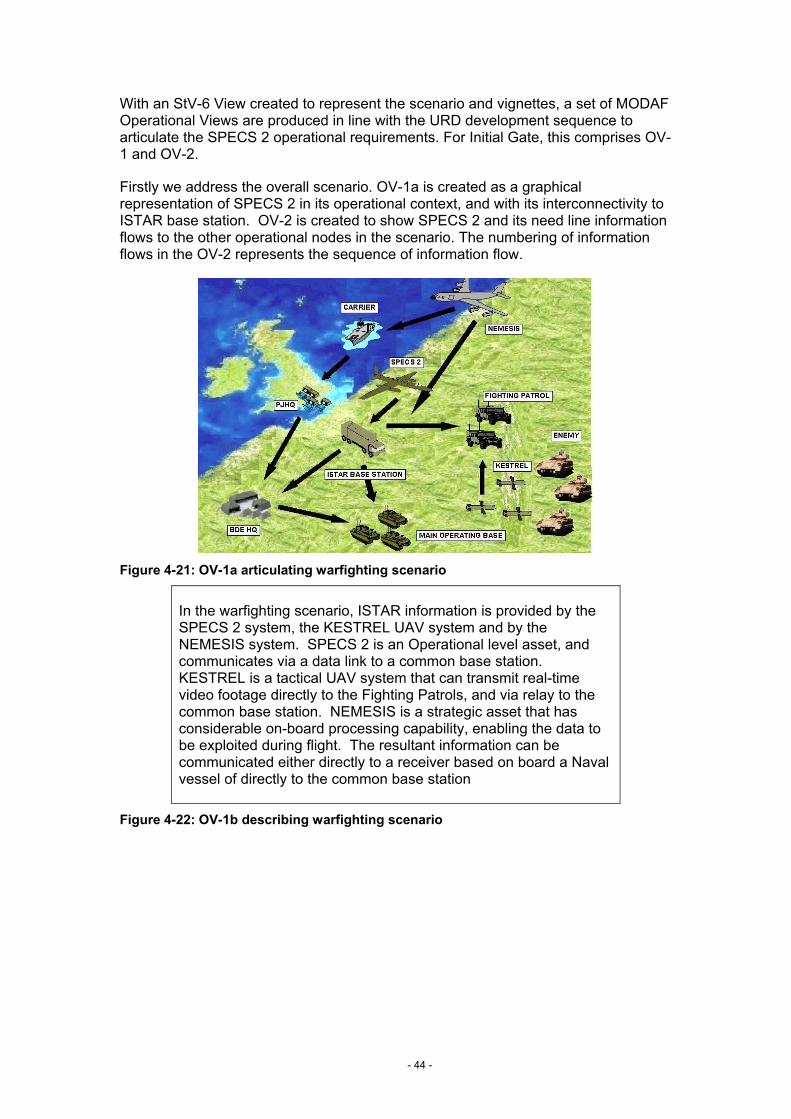
- 44 -
With an StV-6 View created to represent the scenario and vignettes, a set of MODAF Operational Views are produced in line with the URD development sequence to articulate the SPECS 2 operational requirements. For Initial Gate, this comprises OV-1 and OV-2.
Firstly we address the overall scenario. OV-1a is created as a graphical representation of SPECS 2 in its operational context, and with its interconnectivity to ISTAR base station. OV-2 is created to show SPECS 2 and its need line information flows to the other operational nodes in the scenario. The numbering of information flows in the OV-2 represents the sequence of information flow.
Figure 4-21: OV-1a articulating warfighting scenario
In the warfighting scenario, ISTAR information is provided by the SPECS 2 system, the KESTREL UAV system and by the NEMESIS system. SPECS 2 is an Operational level asset, and communicates via a data link to a common base station. KESTREL is a tactical UAV system that can transmit real-time video footage directly to the Fighting Patrols, and via relay to the common base station. NEMESIS is a strategic asset that has considerable on-board processing capability, enabling the data to be exploited during flight. The resultant information can be communicated either directly to a receiver based on board a Naval vessel of directly to the common base station
Figure 4-22: OV-1b describing warfighting scenario
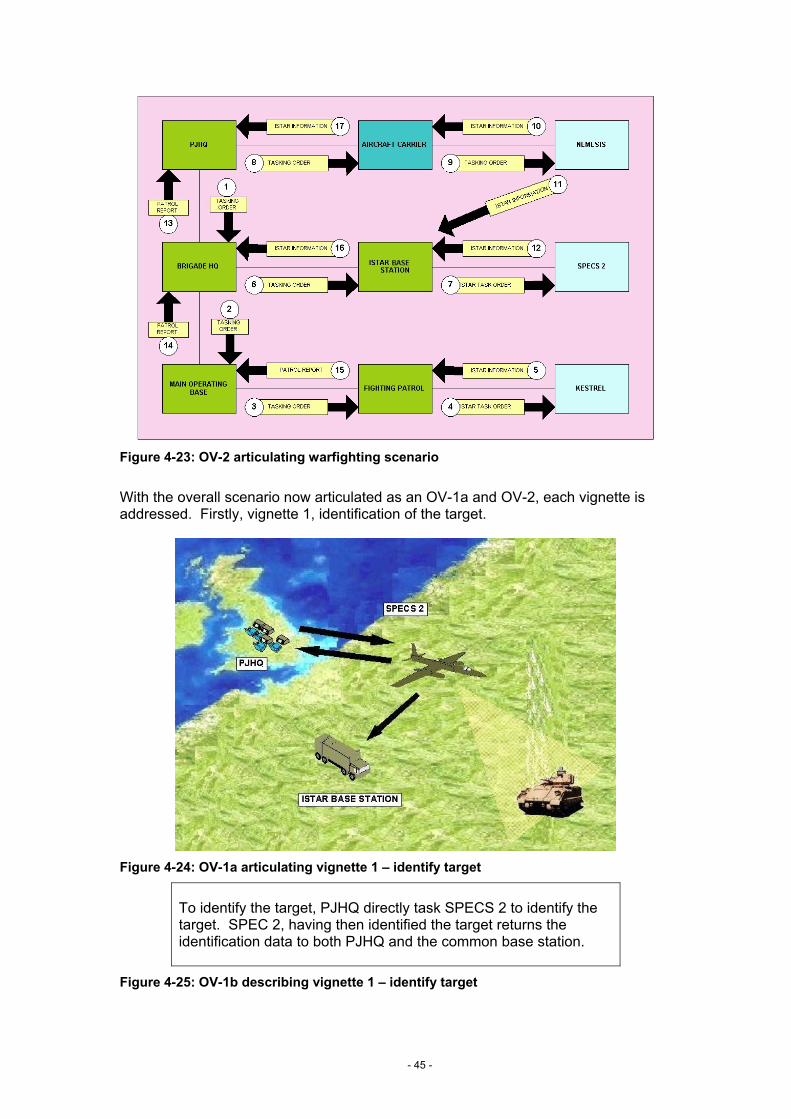
- 45 -
Figure 4-23: OV-2 articulating warfighting scenario
With the overall scenario now articulated as an OV-1a and OV-2, each vignette is addressed. Firstly, vignette 1, identification of the target.
Figure 4-24: OV-1a articulating vignette 1 – identify target
To identify the target, PJHQ directly task SPECS 2 to identify the target. SPEC 2, having then identified the target returns the identification data to both PJHQ and the common base station.
Figure 4-25: OV-1b describing vignette 1 – identify target

- 46 -
PJHQ SPECS 2
ENEMY
ISTAR BASESTATION
ISTAR INFORMATION
ISTAR INFORMATION
ISTAR TASK ORDER
1
2
3
4
ISTAR INFORMATION
Figure 4-26: OV-2 articulating vignette 1 – identify target
Secondly vignette 2, interoperability with US JSTAR to obtain and fuse information.
Figure 4-27: OV-1a articulating vignette 2 – interoperability
PJHQ directly tasks SPECS 2 to fuse information with US JSTAR. SPEC 2 sends its information to USJSTAR, and requests that from US JSTAR in return. It fuses the returning information with that of its own and returns the combined information to PJHQ to complete the order.
Figure 4-28: OV-1b describing vignette 2 – interoperability
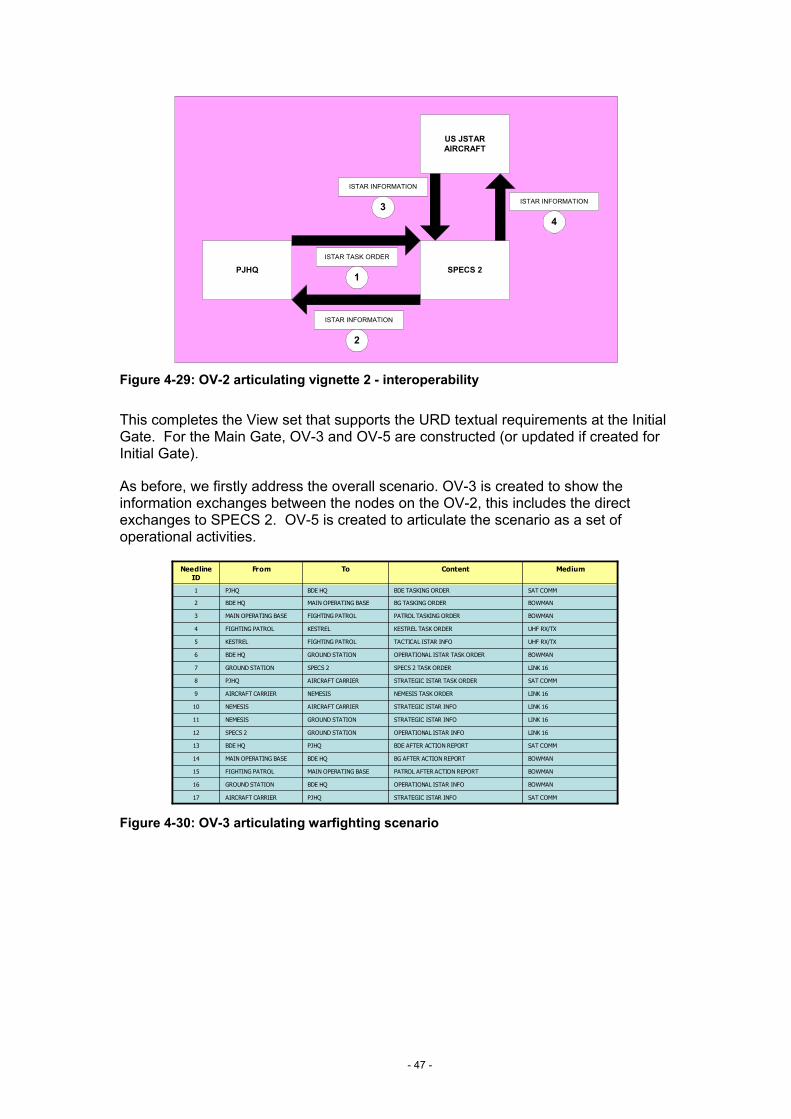
- 47 -
PJHQ SPECS 2
US JSTARAIRCRAFT
ISTAR INFORMATION
ISTAR INFORMATION
ISTAR TASK ORDER
1
2
34
ISTAR INFORMATION
Figure 4-29: OV-2 articulating vignette 2 - interoperability
This completes the View set that supports the URD textual requirements at the Initial Gate. For the Main Gate, OV-3 and OV-5 are constructed (or updated if created for Initial Gate).
As before, we firstly address the overall scenario. OV-3 is created to show the information exchanges between the nodes on the OV-2, this includes the direct exchanges to SPECS 2. OV-5 is created to articulate the scenario as a set of operational activities.
SAT COMMSTRATEGIC ISTAR INFOPJHQAIRCRAFT CARRIER17
BOWMANOPERATIONAL ISTAR INFOBDE HQGROUND STATION16
LINK 16SPECS 2 TASK ORDERSPECS 2GROUND STATION7
SAT COMMSTRATEGIC ISTAR TASK ORDERAIRCRAFT CARRIERPJHQ8
LINK 16NEMESIS TASK ORDERNEMESISAIRCRAFT CARRIER9
LINK 16STRATEGIC ISTAR INFOAIRCRAFT CARRIERNEMESIS10
LINK 16STRATEGIC ISTAR INFOGROUND STATIONNEMESIS11
LINK 16OPERATIONAL ISTAR INFOGROUND STATIONSPECS 212
SAT COMMBDE AFTER ACTION REPORTPJHQBDE HQ13
BOWMANBG AFTER ACTION REPORTBDE HQMAIN OPERATING BASE14
BOWMANPATROL AFTER ACTION REPORTMAIN OPERATING BASEFIGHTING PATROL15
BOWMANOPERATIONAL ISTAR TASK ORDERGROUND STATIONBDE HQ6
UHF RX/TXTACTICAL ISTAR INFOFIGHTING PATROLKESTREL5
UHF RX/TXKESTREL TASK ORDERKESTRELFIGHTING PATROL4
BOWMANPATROL TASKING ORDERFIGHTING PATROLMAIN OPERATING BASE3
BOWMANBG TASKING ORDERMAIN OPERATING BASEBDE HQ2
SAT COMMBDE TASKING ORDERBDE HQPJHQ1
MediumContentToFromNeedline ID
Figure 4-30: OV-3 articulating warfighting scenario

- 48 -
Figure 4-31: OV-5 articulating warfighting scenario
Then OV-3 and OV-5 are created for each vignette. Firstly vignette 1 - SPECS 2 identification of the target.
Figure 4-32: OV-3 articulating vignette 1 – identify target

- 49 -
PJHQ ordersSPECS2 to provideISTAR information
from target area
SPECS 2 acceptsorders
SPECS2 moves toairspace required toprovide information
SPECS2 beginssending back ISTARinformation to PJHQ
and ISTAR basestation
ISTAR Information isanalysed
Targets areidentified
Orders are preparedto prosecute targets
INFORMATION ACQUISITION INFORMATION MANAGEMENT
Figure 4-33: OV-5 articulating vignette 1 – identify target
Secondly, OV-3 and OV-5 are created for vignette 2 - SPECS 2 interoperability with US JSTAR to obtain and fuse information.
Figure 4-34: OV-3 articulating vignette 2 - interoperability

- 50 -
PJHQ informsSPECS2 that
exchnage of ISTARinformation is
possible with JSTAR
SPECS 2acknowledges
SPECS2 initiatescontact with JSTAR
SPECS2 and JSTARexchange ISTAR
information
Fusion of ISTARInformation
ISTAR information isanalysed
SPECS2 sendcollated ISTAR
information to PJHQ
INFORMATION ACQUISITION INFORMATION MANAGEMENT
Figure 4-35: OV-5 articulating vignette 2 – interoperability
The OV-3 tables can contain a number of columns beyond that shown; the detail of these are contained in the Technical Handbook13.
This completes the MODAF Operational View suite required to support the textual requirements at the Main Gate.
In additional to the Operational View Suite, the Main Gate requires TV-1, to specify the policies and standards that SPECS 2 must satisfy. The TV-1 for SPECS 2 is shown in Figure 4-36.
Service Area Service System Elements
Standard / Policy
Data Transfer TCP/IP BOWMAN IP v6
Messaging Email BISA / Comms
MS Outlook CompliantJSP 324
Operating Systems
Workstations BISA / Control Stations
Data Interchange
Interoperability OMG XMI 2.1
Deployed Units LAND Units JSPs, SOPs,
Service Area Service System Elements
Standard / Policy
Data Transfer TCP/IP BOWMAN IP v6
Messaging Email BISA / Comms
MS Outlook CompliantJSP 324
Operating Systems
Workstations BISA / Control Stations
Data Interchange
Interoperability OMG XMI 2.1
Deployed Units LAND Units JSPs, SOPs,
Service AreaService AreaService Area ServiceServiceService System ElementsSystem
ElementsSystem
ElementsStandard / PolicyStandard / PolicyStandard / Policy
Data TransferData TransferData Transfer TCP/IPTCP/IPTCP/IP BOWMANBOWMANBOWMAN IP v6IP v6IP v6
MessagingMessagingMessaging EmailEmailEmail BISA / CommsBISA / CommsBISA / Comms
MS Outlook CompliantJSP 324
MS Outlook CompliantJSP 324
MS Outlook CompliantJSP 324
Operating SystemsOperating SystemsOperating Systems
WorkstationsWorkstationsWorkstations BISA / Control Stations
BISA / Control Stations
BISA / Control Stations
Data InterchangeData InterchangeData Interchange
InteroperabilityInteroperabilityInteroperability OMG XMI 2.1OMG XMI 2.1OMG XMI 2.1
Deployed UnitsDeployed UnitsDeployed Units LAND UnitsLAND UnitsLAND Units JSPs, SOPs, JSPs, SOPs, JSPs, SOPs,
Figure 4-36: TV-1 specifying SPECS 2 standards and policies
13 MODAF Technical Handbook. Reference: MODAF-M07-022

- 51 -
4.7 Summary
This example provides a simplified explanation of how MODAF can be applied within Customer 1. Notice how common data elements across MODAF views bear the same name and relationships in each view. This is what distinguishes MODAF from the generation of custom views. The consistency of the data elements and relationships provided by the meta-model ensures the architecture is integral, and delivers the benefits resulting from a commonality of language in the architectural framework.
In a real example the number of Systems involved, the variety and depth of the Capability Taxonomy, and the multiple dependencies across DECs, DPA and the DLO will be greatly increased. As MODAF View development is an iterative process for each View, it is certain that there will be several versions to allow comparison and evaluation.

- 52 -
5. Document Maintenance
It is intended that the MODAF product suite will evolve through time in order to reflect learning from experience, changes to the MOD’s processes and the evolution of architectural best practice. A change control process will be established for all MODAF products and suggestions upon the refinement / improvement of this and related products are welcome. The formal MODAF change control process shall be published in due course (see www.modaf.com). In the interim, suggestions should be forwarded to the MODAF project manager:
EC CCII I2b
Tel: 0207 807 8884
Acknowledgements
This document has been developed by MODAF partners as part of the MODAF 1.0 Baseline that is being prepared by DEC CCII supported by the IA. Other organisations that have contributed to the content and / or review of this document are:
• DCBM(Army)
• DEC CCII Capability Strategy
• DEC UWE
The role of Industry is also acknowledged in providing support to the MODAF development and in reviewing the MODAF products prior to its release.
MODAF partners
The MODAF 1.0 Baseline has been developed for the MOD by MODAF partners. The MODAF partners team leaders for this work have been:
Fariba Hozhabrafkan
Cornwell Management Consultants Home Barn Court The Street Effingham Surrey KT24 5LG
Tel: 01372 456086
Dave Mawby
PA Consulting Group 123 Buckingham Palace Road London SW1W 9SR
Tel: 020 7730 9000
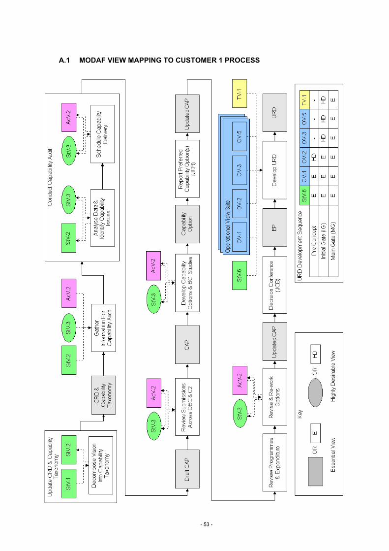
- 53 -
A.1 MODAF VIEW MAPPING TO CUSTOMER 1 PROCESS