Embed Size (px)
Citation preview

ASSEMBLY GUIDE2018 EDITION v2.2
ReActiveMicroSince 2005
M O C K I N G B O A R D

CONTENTS
KIT ASSEMBLY 1 Complete List 1 Assembly Parts 2 Fully Assembled Card 2
COMPONENTS 3 Circuit Board - PCB 3 Integrated Circuit – IC Chips 3 Capacitors 4 Diodes 5 Resistors 6
4-Band Resistor 6 5-Band Resistor 7
SOUND CONNECTOR 8 SPEECH CHIP OPTION 9 LIVE ASSEMBLY 10
Joe Strosnider Assembly & Review 10 Chris Torrence's Assembly and Overview 10
MAIN COMPONENTS OVERVIEW 11 R6522 Versatile Interface Adapter 11 SSI 263A Phoneme Speech Synthesizer 12 AY-3-8913 13
DISCLAIMER 14
MOCKINGBOARD
ReActiveMicro.com KIT ASSEMBLY
1 Rev. 1 - 12/27/2018 1:35 PM
✗
TOC KIT ASSEMBLY
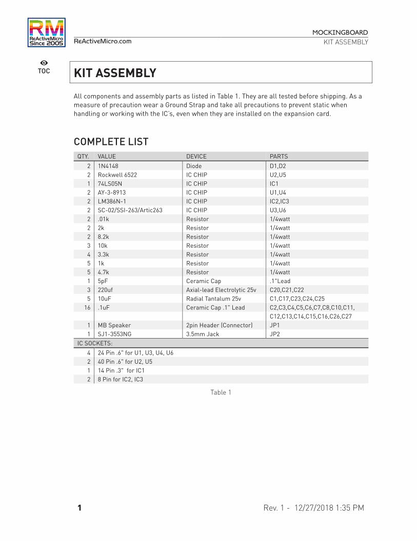
All components and assembly parts as listed in Table 1. They are all tested before shipping. As a measure of precaution wear a Ground Strap and take all precautions to prevent static when handling or working with the IC’s, even when they are installed on the expansion card.
COMPLETE LIST QTY. VALUE DEVICE PARTS
2 1N4148 Diode D1,D2 2 Rockwell 6522 IC CHIP U2,U5 1 74LS05N IC CHIP IC1 2 AY-3-8913 IC CHIP U1,U4 2 LM386N-1 IC CHIP IC2,IC3 2 SC-02/SSI-263/Artic263 IC CHIP U3,U6 2 .01k Resistor 1/4watt 2 2k Resistor 1/4watt 2 8.2k Resistor 1/4watt 3 10k Resistor 1/4watt 4 3.3k Resistor 1/4watt 5 1k Resistor 1/4watt 5 4.7k Resistor 1/4watt 1 5pF Ceramic Cap .1"Lead 3 220uf Axial-lead Electrolytic 25v C20,C21,C22 5 10uF Radial Tantalum 25v C1,C17,C23,C24,C25
16 .1uF Ceramic Cap .1" Lead C2,C3,C4,C5,C6,C7,C8,C10,C11, C12,C13,C14,C15,C16,C26,C27
1 MB Speaker 2pin Header (Connector) JP1 1 SJ1-3553NG 3.5mm Jack JP2
IC SOCKETS: 4 24 Pin .6" for U1, U3, U4, U6 2 40 Pin .6" for U2, U5 1 14 Pin .3" for IC1 2 8 Pin for IC2, IC3
Table 1

MOCKINGBOARD
ReActiveMicro.com KIT ASSEMBLY
2 Rev. 1 - 12/27/2018 1:35 PM
✗
TOC ASSEMBLY PARTS The components/parts included with your assembly kit and the PCB have basic labels as seen in Figure 1. There are 315 pads which need to be soldered. Those with intermediate knowledge should have little trouble assembling the kit from just these labels.
Figure 1
FULLY ASSEMBLED CARD A fully assembled MOCKINGBOARD v2.2 as seen in Figure 2 can also be used for reference or determine orientation of components.
Figure 2

MOCKINGBOARD
ReActiveMicro.com KIT ASSEMBLY
3 Rev. 1 - 12/27/2018 1:35 PM
✗
TOC COMPONENTS
CIRCUIT BOARD - PCB The printed circuit board has “square pads” (the soldering hole for placement of the components) to denote the POSTIVE side of ALL items with a polarity or Pin 1 of the IC’s.
INTEGRATED CIRCUIT – IC CHIPS Table 2 represents the main components of the MOCKINGBOARD. Take notice that the LM386 IC’s shown in Table 3 are facing a different direction then the rest of the IC’s. Make sure to install all IC Chips correctly or damage to the card and/or computer may occur.
Interface IC Sound Generator Speech Synthesizer
R6522P AY-3-8913 SC-02 / Arctic-02,
SSI-263P, SSI-263AP or 78A263A-P
Table 2
Logic IC Audio Amp.
74LS05N LM386N (Audio Amp)
Table 3
Note: IC chips shown in Table 2 and 3 are not to scale, and may not have the exact same markings as those in the assembly kit, such as the manufacturer, however the identification of the chip such as SN74LS05N will be the same, no matter which company produced the IC chip.

MOCKINGBOARD
ReActiveMicro.com KIT ASSEMBLY
4 Rev. 1 - 12/27/2018 1:35 PM
✗
TOC CAPACITORS
Positive + Negative -
Axial-lead Aluminum Tantalum Disc Ceramic
Table 4
Note: The assembly kit may include three types of capacitors, or “caps” for short as seen in Table 4. The images shown are not to scale and all caps will have value markings on them, 106 is 10µf and 104 is .1µf. This will help identify the different caps in the kit.
The Aluminum Electrolytic caps have axial leads on both ends, cylindrical aluminum case, insulated with a blue sleeve. A strip pointing to the NEGATIVE - end lead. The Tantalum caps will generally have a marking or stripe to denote (not always pointing to) the POSITIVE lead.
CONSTRUCTION NOTES
The PCB will be clearly marked with + signs for all cap locations when the orientation of the part matters, or a polarized part is normally used. Sometimes a non-polarized part is used in place of a polarized one and then its orientation does not matter. A polarized cap installed backwards may damage the component. Pay attention to the “Positive” side of the 10uF caps, 220uF cap and make sure to install them in the correct polarity on the card. The 10µF caps have a line and a small + sign on the positive side and the card is marked with a + sign to denote positive. The 220µF caps have a line and a small - with an > sign pointing toward the negative side and the card is marked with a + sign to denote positive.

MOCKINGBOARD
ReActiveMicro.com KIT ASSEMBLY
5 Rev. 1 - 12/27/2018 1:35 PM
✗
TOC DIODES The assembly kit includes two diodes. The diagram and image of a diode can be seen in Table 5. The two diode components properly assembled to the MOCKINGBOARD are located below the AY-3 Chip and above the MB speaker connector as seen in Figure 2.
Anode + Cathode -
Table 5
CONSTRUCTION NOTES
Pay attention to the Positive + side of the 1N4148 diodes and make sure to install them in the correct polarity on the card. The diodes have a Black Stripe that runs the circumference on the glass casing that denotes the Negative - side. Make sure the stripe on the diode is facing the Stereo Jack on the card.

MOCKINGBOARD
ReActiveMicro.com KIT ASSEMBLY
6 Rev. 1 - 12/27/2018 1:35 PM
✗
TOC RESISTORS Your kit may include the less precise 4 band style Table 6, which are typically 5% tolerance, or the more precise 5 band style Table 7, which are typically 1% tolerance. Refer to the following charts on how to read them and to help make matching locations on the PCB easier.
4-Band Resistor
1st digit 2nd digit Multiplier Tolerance 0 0 x 1 1 1 x 10 ±1% 2 2 x 100 ±2% 3 3 x 1k 4 4 x 10k 5 5 x 100k 6 6 x 1M 7 7 8 8 x 0.1 ±5% 9 9 x 0.01 ±10%
Table 6
Example: Band 1 = Brown, Band 2 = Black, Band 3 = Red, Band 4 = Gold Resistor Value: 1 (Brown) 0 (Black) x 100 (Red) = 10 x 100 = 1,000 with a 5% tolerance Band 4 (Gold) = 1kΩ (Kilo ohm)

MOCKINGBOARD
ReActiveMicro.com KIT ASSEMBLY
7 Rev. 1 - 12/27/2018 1:35 PM
✗
TOC 5-Band Resistor
Color 1st Band Value 2nd Band Value 3rd Band Value Multiplier Tolerances
Black 0 0 0 x 1
Brown 1 1 1 x 10 ±1%
Red 2 2 2 x 100 ±2%
Orange 3 3 3 x 1,000 ±3%
Yellow 4 4 4 x 10,000 ±4%
Green 5 5 5 x 100,000 ±0.5%
Blue 6 6 6 x 1,000,000 ±0.25%
Violet 7 7 7 x 10,000,000 ±0.10%
Grey 8 8 8 x 100,000,000 ±0.05%
White 9 9 9 x 1,000,000,000
Gold x 0.1 ±5%
Silver x 0.01 ±10%
No band ±20%
Table 7

MOCKINGBOARD
ReActiveMicro.com KIT ASSEMBLY
8 Rev. 1 - 12/27/2018 1:35 PM
✗
TOC SOUND CONNECTOR
The Motherboard (MB) sound connection on the card is connected with a 2 pin cable as seen in Figure 3 to the Apple II Motherboard. Disconnect the II's speaker and connect the 2 pin cable to the motherboard and MOCKINGBOARD.
Turn on the Apple II computer and if you hear the system beep through your speakers then the cable is connected correctly. If no sound is heard, then reverse one of the cable connections and reconnect. If still no sound is heard, then there is an issue with the cable or the MOCKINGBOARD.
Figure 3

MOCKINGBOARD
ReActiveMicro.com KIT ASSEMBLY
9 Rev. 1 - 12/27/2018 1:35 PM
✗
TOC SPEECH CHIP OPTION
The speech chip(s) as seen in Table 2 can be installed on the (PCB) board. The board can accommodate two of these speech chips, both areas on the board are labelled SSI-263AP, the top socket is the primary socket when installing only one of these chips. The Speech Chips maybe labelled as follows:
• SC-02 • Arctic-02 • SSI-263P • SSI-263AP or 78A263A-P

MOCKINGBOARD
ReActiveMicro.com KIT ASSEMBLY
10 Rev. 1 - 12/27/2018 1:35 PM
✗
TOC LIVE ASSEMBLY
On February 8th, 2018 Joe Strosnider made an assembly and review of the MOCKINGBOARD v2.1 Kit. He gives some very good feedback and shows his own assembly of the project. The kit is so simple to assemble with some basic knowledge that as Joe has little issue completing his work. On February 20th, 2018 Chris Torrence's Assembly Lines #62 video podcast did a review of the MOCKINGBOARD v2.1. He doesn't show full assembly like Joe Strosnider does, but it's still a good video to learn more in depth about the project and parts as well as mods, pics, and testing.
Joe Strosnider Assembly & Review of the MOCKINGBOARD v2.1
Chris Torrence's Assembly and Overview of the MOCKINGBOARD v2.1

MOCKINGBOARD
ReActiveMicro.com KIT ASSEMBLY
11 Rev. 1 - 12/27/2018 1:35 PM
✗
TOC MAIN COMPONENTS OVERVIEW
R6522 VERSATILE INTERFACE ADAPTER Adapted from Rockwell Document No. 29000D47 Rev. 8, October 1984 The R6522 Versatile Interface Adapter (VIA) is a very flexible I/O control device. In addition, this device contains a pair of very powerful 16-bit interval timers, a serial-to-parallel/parallel-to serial shift register and input data latching on the peripheral ports. Expanded handshaking capability allows control of bidirectional data transfers between VIA's in multiple processor systems. Control of peripheral devices is handled primarily through two 8-bit bidirectional ports. Each line can be programmed as either an input or an output. Several peripheral I/O lines can be controlled directly from the interval timers for generating programmable frequency square waves or for counting externally generated pulses. To facilitate control of the many powerful features of this chip, an interrupt flag register, an interrupt enable register and a pair of function control registers are provided.
FEATURES Two 8-bit bidirectional I/0 ports. Expanded “handshake” capability allows positive
control of data transfers between processor and peripheral devices.
Two 16-bit programmable timer/counters.
Serial data port. TTL compatible. Latched output and input registers. CMOS compatible peripheral control lines. 1 MHz and 2 MHz operation. Single +5V power supply.

MOCKINGBOARD
ReActiveMicro.com KIT ASSEMBLY
12 Rev. 1 - 12/27/2018 1:35 PM
✗
TOC SSI 263A PHONEME SPEECH SYNTHESIZER Adapted from Silicon Systems Data Sheet - 09/85 The SSI 263A Is a versatile, high-quality, phoneme based speech synthesizer circuit contained in a single monolithic CMOS Integrated circuit. It is designed to produce an audio output of unlimited vocabulary, music and sound effects at an extremely low data Input rate. Speech Is synthesized by combining phonemes, the building blocks of speech, in an appropriate sequence. The SSI 263A contains five eight-bit registers that allow software control of speech rate, pitch, pitch movement rate, amplitude, articulation rate, vocal tract filter response, and phoneme selection and duration.
FEATURES Single low-power CMOS Integrated circuit. Non-dedicated speech, Ideal for text-to-speech
programming. 5 Volt supply.
Extremely low data rate. Programmable and hard power down/reset mode. 8-bit bus compatible with selectable handshaking modes.
Switched-capacitor-filter technology.

MOCKINGBOARD
ReActiveMicro.com KIT ASSEMBLY
13 Rev. 1 - 12/27/2018 1:35 PM
✗
TOC AY-3-8913 Information datasheet adapted from General Instruments Corporation. The AY-3-8913 is a register oriented Programmable Sound Generator (PSG). Communication between the processor and the PSG is based on the concept of memory-mapped I/O. Control commands are issued to the PSG by writing to 16 memory-mapped registers. Each of the 16 registers within the PSG is also readable so that the microprocessor can determine, as necessary, present states or stored data values. All functions of the PSG are controlled through the 16 registers which once programmed, generate and sustain the sounds, thus freeing the Apple II system processor for other tasks. The (PSG) is a LSI Circuit which can produce a wide variety of complex sounds under software control. The (PSG) flexibility makes it useful in applications such as music synthesis, sound effects generation. The analog sound outputs can each provide 4 bits of logarithmic digital to analog conversion. greatly enhancing the dynamic range of the sounds produced. In order to perform sound effects while allowing the Apple II processor to continue its other tasks, the (PSG) can continue to produce sound after the initial commands have been given by the control processor. The fact that realistic sound production often involves more than one effect is satisfied by the three independently controllable channels available in the (PSG). All of the circuit control signals are digital in nature and intended to be provided directly by the Apple II microprocessor, this means that one (PSG) can produce the full range of required sounds with no change in external circuitry. Since the frequency response of the (PSG) ranges from sub-audible at its lowest frequency to post-audible at its highest frequency, there are few sounds which are beyond reproduction with only the simplest electrical connections.
FEATURES Full Software Control of Sound Generation Three Independently Programmed Analog Outputs
The AY-3-8913 has no ports and 24 leads Single +5 Volt Supply

MOCKINGBOARD
ReActiveMicro.com KIT ASSEMBLY
14 Rev. 1 - 12/27/2018 1:35 PM
✗
TOC DISCLAIMER
ReActiveMicro, and all persons acting on its behalf, disclaim any and all liability for any errors, inaccuracies or incompleteness contained in this assembly guide and any and all referring links included those found on the referred websites: Wiki and YouTube. ReActiveMicro reserves the right to make changes to any items herein to improve reliability, function or design. ReActiveMicro does not assume any liability arising out of the application or use of any product or circuit described herein.
• ReActiveMicro, and all persons acting on its behalf, disclaim any and all liability for any errors, inaccuracies or incompleteness contained in this assembly guide and any and all referring links included those found on the referred websites: Wiki and YouTube.
• ReActiveMicro reserves the right to make changes to any items herein to improve reliability, function or design.
• ReActiveMicro does not assume any liability arising out of the application or use of any product or circuit described herein

ReActiveMicroSince 2005