Embed Size (px)
Citation preview

MOBILETELECOMMUNICATIONS
PROTOCOLS FORDATA NETWORKS
Mobile Telecommunications Protocols For Data Networks. Anna HacCopyright 2003 John Wiley & Sons, Ltd.
ISBN: 0-470-85056-6

MOBILETELECOMMUNICATIONS
PROTOCOLS FORDATA NETWORKS
Anna HacUniversity of Hawaii at Manoa, Honolulu

Copyright 2003 John Wiley & Sons Ltd, The Atrium, Southern Gate, Chichester,West Sussex PO19 8SQ, England
Telephone (+44) 1243 779777
Email (for orders and customer service enquiries): [email protected] our Home Page on www.wileyeurope.com or www.wiley.com
All Rights Reserved. No part of this publication may be reproduced, stored in a retrieval system ortransmitted in any form or by any means, electronic, mechanical, photocopying, recording, scanning orotherwise, except under the terms of the Copyright, Designs and Patents Act 1988 or under the terms ofa licence issued by the Copyright Licensing Agency Ltd, 90 Tottenham Court Road, London W1T 4LP,UK, without the permission in writing of the Publisher. Requests to the Publisher should be addressedto the Permissions Department, John Wiley & Sons Ltd, The Atrium, Southern Gate, Chichester, WestSussex PO19 8SQ, England, or emailed to [email protected], or faxed to (+44) 1243 770571.
This publication is designed to provide accurate and authoritative information in regard to the subjectmatter covered. It is sold on the understanding that the Publisher is not engaged in renderingprofessional services. If professional advice or other expert assistance is required, the services of acompetent professional should be sought.
Other Wiley Editorial Offices
John Wiley & Sons Inc., 111 River Street, Hoboken, NJ 07030, USA
Jossey-Bass, 989 Market Street, San Francisco, CA 94103-1741, USA
Wiley-VCH Verlag GmbH, Boschstr. 12, D-69469 Weinheim, Germany
John Wiley & Sons Australia Ltd, 33 Park Road, Milton, Queensland 4064, Australia
John Wiley & Sons (Asia) Pte Ltd, 2 Clementi Loop #02-01, Jin Xing Distripark, Singapore 129809
John Wiley & Sons Canada Ltd, 22 Worcester Road, Etobicoke, Ontario, Canada M9W 1L1
British Library Cataloguing in Publication Data
A catalogue record for this book is available from the British Library
ISBN 0-470-85056-6
Typeset in 10/12pt Times by Laserwords Private Limited, Chennai, IndiaPrinted and bound in Great Britain by TJ International, Padstow, CornwallThis book is printed on acid-free paper responsibly manufactured from sustainable forestryin which at least two trees are planted for each one used for paper production.

Contents
Preface ix
About the Author xiii
1 Mobile Agent Platforms and Systems 11.1 Mobile Agent Platforms 1
1.1.1 Grasshopper 21.1.2 Aglets 21.1.3 Concordia 31.1.4 Voyager 31.1.5 Odyssey 3
1.2 Multiagent Systems 31.2.1 Agent-based load control strategies 5
1.3 Summary 9Problems to Chapter 1 10
2 Mobile Agent-based Service Implementation, Middleware,and Configuration 112.1 Agent-based Service Implementation 112.2 Agent-based Middleware 172.3 Mobile Agent-based Service Configuration 232.4 Mobile Agent Implementation 282.5 Summary 29
Problems to Chapter 2 29
3 Wireless Local Area Networks 333.1 Virtual LANs 33
3.1.1 Workgroup management 353.1.2 Multicast groups 36
3.2 Wideband Wireless Local Access 373.2.1 Wideband wireless data access based on OFDM
and dynamic packet assignment 373.2.2 Wireless services support in local multipoint distribution
systems 39
vi CONTENTS
3.2.3 Media Access Control (MAC) protocols for widebandwireless local access 41
3.2.4 IEEE 802.11 413.2.5 ETSI HIPERLAN 443.2.6 Dynamic slot assignment 46
3.3 Summary 50Problems to Chapter 3 51
4 Wireless Protocols 554.1 Wireless Protocol Requirements 564.2 MAC Protocol 564.3 Broadband Radio Access Integrated Network 584.4 Hybrid and Adaptive MAC Protocol 594.5 Adaptive Request Channel Multiple Access Protocol 604.6 Request/Acknowledgement Phase 614.7 Permission/Transmission Phase 624.8 Performance Analysis 654.9 Performance Measures 674.10 Summary 69
Problems to Chapter 4 70
5 Protocols for Wireless Applications 735.1 Wireless Applications and Devices 735.2 Mobile Access 795.3 XML Protocol 805.4 Data Encapsulation and Evolvability 825.5 Wireless Application Protocol (WAP) 855.6 Summary 88
Problems to Chapter 5 89
6 Network Architecture Supporting Wireless Applications 936.1 WAE Architecture 936.2 WTA Architecture 986.3 WAP Push Architecture 1056.4 Summary 109
Problems to Chapter 6 109
7 XML, RDF, and CC/PP 1117.1 XML Document 1117.2 Resource Description Framework (RDF) 1147.3 CC/PP – User Side Framework for Content Negotiation 1197.4 CC/PP Exchange Protocol based on the HTTP Extension
Framework 1297.5 Requirements for a CC/PP Framework, and the Architecture 132
CONTENTS vii
7.6 Summary 135Problems to Chapter 7 135
8 Architecture of Wireless LANs 1398.1 Radio Frequency Systems 1408.2 Infrared Systems 1418.3 Spread Spectrum Implementation 141
8.3.1 Direct sequence spread spectrum 1418.3.2 Frequency hopping spread spectrum 1428.3.3 WLAN industry standard 142
8.4 IEEE 802.11 WLAN Architecture 1438.4.1 IEEE 802.11a and IEEE 802.11b 145
8.5 Bluetooth 1468.5.1 Bluetooth architecture 1478.5.2 Bluetooth applications 1528.5.3 Bluetooth devices 154
8.6 Summary 157Problems to Chapter 8 158
9 Routing Protocols in Mobile and Wireless Networks 1639.1 Table-driven Routing Protocols 164
9.1.1 Destination-sequenced distance-vector routing 1649.1.2 The wireless routing protocol 1669.1.3 Global state routing 1669.1.4 Fisheye state routing 1679.1.5 Hierarchical state routing 1679.1.6 Zone-based hierarchical link state routing protocol 1689.1.7 Cluster-head gateway switch routing protocol 168
9.2 On-demand Routing Protocols 1699.2.1 Temporally ordered routing algorithm 1699.2.2 Dynamic source routing protocol 1719.2.3 Cluster-based routing protocol 1739.2.4 Ad hoc on-demand distance-vector routing 1749.2.5 Signal stability-based adaptive routing 1759.2.6 Associativity-based routing 1769.2.7 Optimized link state routing 1779.2.8 Zone routing protocol 1779.2.9 Virtual subnets protocol 178
9.3 Summary 179Problems to Chapter 9 179
10 Handoff in Mobile and Wireless Networks 18110.1 Signaling Handoff Protocol in WATM Networks 18410.2 Crossover Switch Discovery 185
viii CONTENTS
10.3 Rerouting Methods 18710.4 Optimized COS Discovery through Connection Grouping 18810.5 Schedule-assisted Handoffs 18910.6 Handoff in Low Earth Orbit (LEO) Satellite Networks 18910.7 Predictive Reservation Policy 19010.8 Chaining Approaches 191
10.8.1 Hop-limited handoff scheme 19110.8.2 Chaining followed by make-break 191
10.9 Analysis of Chaining Handoff Approaches 19310.10 Summary 194
Problems to Chapter 10 194
11 Signaling Traffic in Wireless ATM Networks 19711.1 A Model of WATM Network 19711.2 Chain Routing Algorithm 19911.3 Implementation of the Handoff Scheme 20211.4 Analysis of the Chain Routing Algorithm 203
11.4.1 Comparison of chain routing algorithm with hop-limitedmethod 203
11.4.2 Analysis of the signaling traffic cost 20511.4.3 Handoff latency 207
11.5 Summary 210Problems to Chapter 11 210
12 Two-phase Combined QoS-based Handoff Scheme 21312.1 Wireless ATM Architecture 21412.2 Mobility Support in Wireless ATM 21712.3 Comparison of Rerouting Schemes 22212.4 Maintaining the Cell Sequence During Path Optimization 22412.5 Combined QoS-based Path Optimization Scheme 22712.6 Summary 230
Problems to Chapter 12 230
References 233
Index 239

Preface
Mobile telecommunications emerged as a technological marvel allowing for access topersonal and other services, devices, computation and communication, in any place andat any time through effortless plug and play. This brilliant idea became possible as theresult of new technologies developed in the areas of computers and communications thatwere made available and accessible to the user.
This book describes the recent advances in mobile telecommunications and their pro-tocols. Wireless technologies that expanded to a wide spectrum and short-range accessallow a large number of customers to use the frequency spectrum when they need it.Devices are used to communicate with the expanded network. Software systems evolvedto include mobile agents that carry service information that is compact enough to beimplemented in the end user devices.
The area of mobile telecommunications has been growing rapidly as new technologiesemerge. Mobile users are demanding fast and efficient connections that support dataapplications. Extending wireless access to the applications requires creating mobile agents,systems, and platforms to implement service configuration. Wireless Local Area Networks(LANs) supporting a growing number of users and applications require wideband wirelesslocal access, wireless protocols, and virtual LANs. Wireless applications require protocolsand architecture supporting these applications. Wireless connection has to be provided bythe networks and protocols. Mobile networks must function efficiently by using theirprotocols, performing routing and handoff for mobile users.
This book focuses on the newest technology for mobile telecommunications support-ing data applications. The book provides a real application-oriented approach to solvingmobile communications and networking problems. The book addresses a broad range oftopics from mobile agents and wireless LANs to wireless application protocols, wirelessarchitecture, and mobile networks.
This book proposes a comprehensive design for mobile telecommunications includingmobile agents, access networks, application protocols, architecture, routing, and handoff.For mobile users and data applications, these are new networking and communicationssolutions, particularly for the LAN environment. The book describes the aspects of mobiletelecommunications for applications, networking, and transmission. Additionally, it intro-duces and analyzes architecture and design issues in mobile communications and networks.
The book is organized into 12 chapters. The first seven chapters describe applications,their protocols and mobile and wireless network support for them. Chapters 8 through12 describe architecture of mobile and wireless networks, their protocols, and quality-of-service (QoS) issues.

x PREFACE
The goal of this book is to explain how to support modern mobile telecommunications,which evolve toward value-added, on-demand services, in which the need for communica-tion becomes frequent and ongoing, and the nature of the communication becomes morecomplex. Mobile agents are used to enable on-demand provision of customized services.Examples of mobile agent-based service implementation, middleware, and configurationare introduced.
Mobile applications are supported by wireless LANs. Virtual LANs provide supportfor workgroups that share the same servers and other resources over the network.
Orthogonal Frequency Division Multiplex (OFDM) allows individual channels to main-tain their orthogonality, or distance, to adjacent channels. This technique allows datasymbols to be reliably extracted and multiple subchannels to overlap in the frequencydomain for increased spectral efficiency. The IEEE 802.11 standards group chose OFDMmodulation for wireless LANs operating at bit rates up to 54 Mb s−1 at 5 GHz.
Wideband Code Division Multiple Access (WCDMA) uses 5-MHz channels and sup-ports circuit and packet data access at 384 kb s−1 nominal data rates for macrocellularwireless access. WCDMA provides simultaneous voice and data services. WCDMA isthe radio interface technology for Universal Mobile Telecommunications System (UMTS)networks.
Mobile applications and wireless LANs use wireless protocols. A Media Access Control(MAC) protocol for a wireless LAN provides two types of data-transfer Service AccessPoints (SAP): network and native. The network SAP offers an access to legacy networkprotocols [e.g., IP (Internet Protocol)]. The native SAP provides an extended serviceinterface that may be used by custom network protocols or user applications capable offully exploiting the protocol-specific QoS parameters within the service area.
Limitations of power, available spectrum, and mobility cause wireless data networks tohave less bandwidth and more latency than traditional networks, as well as less connectionstability than other network technologies, and less predictable availability.
Mobile devices have a unique set of features that must be exposed into the WorldWide Web (WWW) in order to enable the creation of advanced telephony services suchas location-based services, intelligent network functionality, including integration into thevoice network, and voice/data integration.
The Wireless Application Protocol (WAP) architecture provides a scalable and exten-sible environment for application development for mobile communication devices. TheWAP protocol stack has a layered design, and each layer is accessible by the layers aboveand by other services and applications. The WAP layered architecture enables other ser-vices and applications to use the features of the WAP stack through a set of well-definedinterfaces. External applications can access the session, transaction, security, and transportlayers directly.
The network architecture supporting wireless applications includes Wireless Appli-cations Environment (WAE), Wireless Telephony Application (WTA), and WAP Pushframework. The WAE architecture is designed to support mobile terminals and networkapplications using different languages and character sets.
WTA is an application framework for telephony services. The WTA user agent has thecapabilities for interfacing with mobile network services available to a mobile telephonydevice, that is, setting up and receiving phone calls.

PREFACE xi
The WAP Push framework introduces a means within the WAP effort to transmitinformation to a device without a previous user action. In the client/server model, a clientrequests a service or information from a server, which transmits information to the client.In this pull technology, the client pulls information from the server.
Extensible Markup Language (XML) is an application profile or restricted form of theStandard Generalized Markup Language (SGML). XML describes a class of data objectscalled XML documents and partially describes the behavior of computer programs thatprocess them. Resource Description Framework (RDF) can be used to create a general,yet extensible, framework for describing user preferences and device capabilities. Thisinformation can be provided by the user to servers and content providers. The servers canuse this information describing the user’s preferences to customize the service or contentprovided.
A Composite Capability/Preference Profile (CC/PP) is a collection of the capabilitiesand preferences associated with the user and the agents used by the user to access theWorld Wide Web (WWW). These user agents include the hardware platform, systemsoftware, and applications used by the user.
In a wireless LAN, the connection between the client and the user exists through the useof a wireless medium such as Radio Frequency (RF) or Infrared (IR) communications.The wireless connection is most usually accomplished by the user having a handheldterminal or a laptop computer that has an RF interface card installed inside the terminalor through the PC (personal computer) card slot of the laptop. The client connection fromthe wired LAN to the user is made through an Access Point (AP) that can support multipleusers simultaneously. The AP can reside at any node on the wired network and performsas a gateway for wireless users’ data to be routed onto the wired network.
A wireless LAN is capable of operating at speeds in the range of 1 or 2, or 11 Mbpsdepending on the actual system. These speeds are supported by the standard for wirelessLAN networks defined by the international body, the IEEE.
The network communications use a part of the radio spectrum that is designated aslicense-free. In this band, of 2.4 to 2.5 GHz, the users can operate without a license whenthey use equipment that has been approved for use in this license-free band. The 2.4-GHzband has been designated as license-free by the International Telecommunications Union(ITU) and is available for use, license-free in most countries in the world.
The ability to build a dynamically scalable network is critical to the viability of awireless LAN as it will inevitably be used in this mode. The interference rejection ofeach node will be the limiting factor to the expandability of the network and its userdensity in a given environment.
In ad hoc networks, all nodes are mobile and can be connected dynamically in anarbitrary manner. All nodes of these networks behave as routers and take part in discoveryand maintenance of routes to other nodes in the network.
An ad hoc network is a collection of mobile nodes forming a temporary networkwithout the aid of any centralized administration or standard support services availablein conventional networks.
Ad hoc networks must deal with frequent changes in topology. Mobile nodes changetheir network location and link status on a regular basis. New nodes may unexpectedly

xii PREFACE
join the network or existing nodes may leave or be turned off. Ad hoc routing protocolsmust minimize the time required to converge after the topology changes.
The ad hoc routing protocols can be divided into two classes: table-driven and on-demand routing on the basis of when and how the routes are discovered. In table-drivenrouting protocols, consistent and up-to-date routing information to all nodes is maintainedat each node, whereas in on-demand routing, the routes are created only when desired bythe source host.
When the mobile end user moves from one AP to another AP, a handoff is required.When the handoff occurs, the current QoS may not be supported by the new data path. Inthis case, a negotiation is required to set up new QoS. Since a mobile user may be in theaccess range of several APs, it will select the AP that provides the best QoS. During thehandoff, an old path is released and then a new path is established. Connection reroutingschemes must exhibit low handoff latency, maintain efficient routes, and limit disruptionto continuous media traffic while minimizing reroute updates to the network switchesand nodes.
Basically, there are three connection rerouting approaches: full connection establish-ment, partial connection re-establishment, and multicast connection re-establishment.
In the wireless Asynchronous Transfer Mode (ATM) network, a radio access layerprovides high-bandwidth wireless transmission with appropriate medium access controland data link control. A mobile ATM network provides base stations (access points)with appropriate support of mobility-related functions, such as handoff and locationmanagement.
QoS-based rerouting algorithm is designed for the two-phase interswitch handoff schemefor wireless ATM networks. Path extension is used for each inter-switch handoff, and pathoptimization is invoked when the handoff path exceeds the delay constraint or maximumpath extension hops constraint. The path optimization schemes include combined QoS-based, delay-based, and hop-based path rerouting schemes.
The content of the book is organized into 12 chapters as follows:Chapter 1 introduces mobile agents and presents platforms and systems to imple-
ment agent-based services in the network. Chapter 2 describes mobile agent-based serviceimplementation. Mobile agent-based middleware and service configuration are introduced.Mobile agent implementation is discussed.
Chapter 3 describes wireless LANs, introduces virtual LANs, and presents widebandwireless local access. Chapter 4 describes wireless protocols.
Protocols for wireless applications are studied in Chapter 5. Wireless applications anddevices are discussed and wireless application protocol is introduced. Network architecturesupporting wireless applications is presented in Chapter 6. Extensible markup language,resource description framework, and composite capability/preference profile are describedin Chapter 7.
Architecture of wireless LANs is studied in Chapter 8. The protocols supporting mobilecommunications, IEEE 802.11 and Bluetooth, are described.
Routing protocols in mobile and wireless networks are presented in Chapter 9. Handoffin mobile networks is described in Chapter 10. Signaling traffic in wireless networks isstudied in Chapter 11. Chapter 12 presents a two-phase combined handoff scheme inwireless networks.

About the Author
Anna Hac received her M.S. and Ph.D. degrees in Computer Science from the Departmentof Electronics, Warsaw University of Technology, Poland, in 1977 and 1982, respectively.
She is a professor in the Department of Electrical Engineering, University of Hawaii atManoa, Honolulu. During her long and successful academic career, she has been a visitingscientist at Imperial College, University of London, England, a postdoctoral fellow at theUniversity of California at Berkeley, an assistant professor of electrical engineering andcomputer science at The Johns Hopkins University, a member of the technical staff atAT&T Bell Laboratories, and a senior summer faculty fellow at the Naval ResearchLaboratory.
Her research contributions include system and workload modeling, performance anal-ysis, reliability, modeling process synchronization mechanisms for distributed systems,distributed file systems, distributed algorithms, congestion control in high-speed networks,reliable software architecture for switching systems, multimedia systems, and wirelessnetworks.
She has published more than 130 papers in archival journals and international con-ference proceedings and is the author of a textbook Multimedia Applications Support forWireless ATM Networks (2000).
She is a member of the Editorial Board of the IEEE Transactions on Multimedia and ison the Editorial Advisory Board of Wiley’s International Journal of Network Management.

1
Mobile agent platformsand systems
Advanced service provisioning allows for rapid, cost-effective service deployment. Mod-ern mobile telecommunications evolve towards value-added, on-demand services in whichthe need for communication becomes frequent and ongoing, and the nature of the commu-nication becomes more complex. The services of the future will be available ‘a la carte’,allowing subscribers to receive content and applications when they want it.
Introducing Mobile Agents (MAs) within the network devices, Mobile Stations (MSs),and Mobile Switching Centers (MSCs) provides the necessary flexibility into the networkand enhanced service delivery. MAs enable on-demand provision of customized servicesvia dynamic agent downloading from the provider system to the customer system ordirectly to the network resources. MAs have the capability to migrate between networks,to customize for the network, and to decentralize service control and management softwareby bringing control and managements agents as close as possible to the resources.
MAs can be used in mobile networks to support advanced service provisioning, as wellas for personal communication, for mobility, and to support Virtual Home Environment(VHE). The VHE agent enables individually subscribed and customized services to followtheir associated users to wherever they roam.
1.1 MOBILE AGENT PLATFORMS
Mobile Agent Technology (MAT) uses interworking between Mobile Agent Platforms(MAPs). Several MAPs are based on Java. These platforms are Grasshopper, Aglets,Concordia, Voyager, and Odyssey.
Each MAP has a class library that allows the user to develop agents and applications.The core abstractions are common to most platforms since they are inherent in the MAparadigm. These abstractions include agents, hosts, entry points, and proxies.
Mobile Telecommunications Protocols For Data Networks. Anna HacCopyright 2003 John Wiley & Sons, Ltd.
ISBN: 0-470-85056-6

2 MOBILE AGENT PLATFORMS AND SYSTEMS
• Agents: In each platform, a base class provides the fundamental agent capability. Insome platforms this base class is used for all agents (static and mobile) while in othersthere are two separate classes.
• Hosts: The terms hosts, environments, agencies, contexts, servers, and AgentPlaces areused to refer to the components of the framework that must be installed at a computernode and that provide the necessary runtime environment for the agents to execute.
• Entry points: The agents have to save the necessary state information to membervariables, allowing the entry point method to proceed depending on the state of thecomputation. Platforms may have one or multiple entry points.
• Proxies: The proxy is a representative that an MA leaves when migrating from a node,and it can be used to forward messages or method invocations to an MA in a location-independent manner. Platforms may implement proxies in different ways. A significantdifference is whether the arbitrary methods of an agent can be called remotely throughthe proxy. Platforms that support this functionality provide a utility that parses a MA’sclass and creates a corresponding proxy. In platforms where arbitrary Remote MethodInvocation (RMI) through a proxy is not supported, the proxy object provides only auniform, generic method to send messages, and therefore no proxy-generation utilityis required.
1.1.1 Grasshopper
The Grasshopper platform consists of a number of agencies (hosts) and a Region Registry(a network-wide database of host and agent information) remotely connected via an ObjectRequest Broker (ORB). Agencies represent the runtime environments for MAs. Severalagencies can be grouped into one region represented by a region registry.
Remote interactions between the components of the Distributed Agent Environment(DAE) are performed via an ORB. The Grasshopper’s Communication Service is a part ofeach agency and region registry. The Grasshopper supports the following protocols: plainsockets (with or without Secure Socket Layer, SSL), Common Object Request BrokerArchitecture (CORBA) Internet Inter – ORB Protocol (IIOP), and RMI – with or withoutSSL. Support for more protocols can be integrated into the communication service.
The Grasshopper platform conforms to the Object Management Group’s (OMG) MobileAgent System Interoperability Facility (MASIF) standard.
1.1.2 Aglets
Aglets (Agent applets) were developed by the IBM Tokyo Research Laboratory. TheAglets class library provides an Application Programming Interface (API) that facilitatesthe encoding of complex agent behavior. Particularly, the way the behavior of the baseAglet class is extended resembles the way Web applets are programmed. Aglets cancooperate with web browsers and Java applets.
The communication API used by Aglets is derived from MASIF standard. The defaultimplementation of the API is the Agent Transfer Protocol (ATP). ATP is an applicationlevel protocol based on TCP and modeled on the Hypertext Transfer Protocol (HTTP)for transmitting messages and MAs between the networked computers in which the hosts
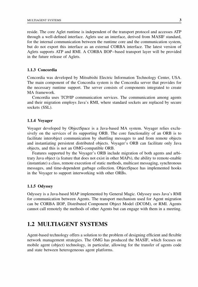
MULTIAGENT SYSTEMS 3
reside. The core Aglet runtime is independent of the transport protocol and accesses ATPthrough a well-defined interface. Aglets use an interface, derived from MASIF standard,for the internal communication between the runtime core and the communication system,but do not export this interface as an external CORBA interface. The latest version ofAglets supports ATP and RMI. A CORBA IIOP–based transport layer will be providedin the future release of Aglets.
1.1.3 Concordia
Concordia was developed by Mitsubishi Electric Information Technology Center, USA.The main component of the Concordia system is the Concordia server that provides forthe necessary runtime support. The server consists of components integrated to createMA framework.
Concordia uses TCP/IP communication services. The communication among agentsand their migration employs Java’s RMI, where standard sockets are replaced by securesockets (SSL).
1.1.4 Voyager
Voyager developed by ObjectSpace is a Java-based MA system. Voyager relies exclu-sively on the services of its supporting ORB. The core functionality of an ORB is tofacilitate interobject communication by shuttling messages to and from remote objectsand instantiating persistent distributed objects. Voyager’s ORB can facilitate only Javaobjects, and this is not an OMG-compatible ORB.
Features supported by the Voyager’s ORB include migration of both agents and arbi-trary Java object (a feature that does not exist in other MAPs), the ability to remote-enable(instantiate) a class, remote execution of static methods, multicast messaging, synchronousmessages, and time-dependent garbage collection. ObjectSpace has implemented hooksin the Voyager to support interworking with other ORBs.
1.1.5 Odyssey
Odyssey is a Java-based MAP implemented by General Magic. Odyssey uses Java’s RMIfor communication between Agents. The transport mechanism used for Agent migrationcan be CORBA IIOP, Distributed Component Object Model (DCOM), or RMI. Agentscannot call remotely the methods of other Agents but can engage with them in a meeting.
1.2 MULTIAGENT SYSTEMS
Agent-based technology offers a solution to the problem of designing efficient and flexiblenetwork management strategies. The OMG has produced the MASIF, which focuses onmobile agent (object) technology, in particular, allowing for the transfer of agents codeand state between heterogeneous agent platforms.
4 MOBILE AGENT PLATFORMS AND SYSTEMS
The Intelligent Network (IN) was developed to introduce, control, and manage servicesrapidly, cost effectively, and in a manner not dependent on equipment and software fromparticular equipment manufactures. The architecture of an IN consists of the followingnode types: Service Switching Points (SSPs), Service Control Points (SCPs), ServiceData Points (SDPs), and Intelligent Peripherals (IP). These nodes communicate with eachother by using a Signaling System No. 7 (SS7) network. SSPs facilitate end user accessto services by using trigger points for detection of service access codes. SCPs form thecore of the architecture; they receive service requests from SSPs and execute the servicelogic. SCPs are assisted by SDPs, which store service/customer related data, and by IPs,which provide services for interaction with end users (e.g., automated announcements ordata collection).
IN overloads occur when the load offered to one or more network resources (e.g.,SCP processors) exceeds the resource’s maximum capacity. Because of the central roleplayed by the SCP, the overall goal of most IN load control mechanisms is to protect SCPprocessors from overload. The goal is to provide customers with high service availabilityand acceptable network response times, even during periods of high network loading.Load control mechanisms are designed to be
• efficient – keeping SCP utilization high at all times;• scalable – suited to all networks, regardless of their size and topology;• responsive – reacting quickly to changes in the network or offered traffic levels;• fair – distributing system capacity among network users and service providers in a
manner deemed fair by the network operator;• stable – avoiding fluctuations or oscillations in resources utilization;• simple – in terms of ease of implementation.
The majority of IN load control mechanisms are node-based, focusing on protect-ing individual nodes in the network (typically SCPs) from overload. Jennings et al.argue that node-based mechanisms cannot alone guarantee that desired Quality of Ser-vice (QoS) levels are consistently achieved. The following observations support thisviewpoint:
• Most currently deployed node-based mechanisms were designed for standard telephonytraffic patterns. Present and future INs support a large number of heterogeneous services,each exhibiting changing traffic characteristics that cannot be effectively controlled byusing node-based techniques.
• Existing node-based overload protection mechanisms serve to protect individual nodesonly and may cause the propagation of traffic congestion, resulting in adverse effectson the service completion rates of the network as a whole.
• Typically node-based mechanisms do not interact effectively with the protection mech-anisms that are incorporated into the signaling networks that carry information betweenthe nodes in a network.
• Node-based controls typically focus on SCP protection only.• Telecommunications equipment manufactures implement node-based mechanisms on a
proprietary basis. This can lead to difficulties in effectively controlling traffic in INsthat contain heterogeneous types of equipment.

MULTIAGENT SYSTEMS 5
While flexible and adaptable network-based load control mechanisms can be imple-mented by using standard software engineering techniques, Jennings et al. argue that thereare many advantages of adopting an agent-based approach:
• Methodology : The agent paradigm encourages an information-centered approach toapplication development; thus it provides a useful methodology for the developmentof control mechanisms that require manipulation of large amounts of data collectedthroughout the network.
• Agent communication languages: Advanced communication languages allow agentsto negotiate in advance the semantics of future communications. This is not presentin traditional communications protocols and can be used in mechanisms that adapt todynamic network environments in which, for instance, traffic patterns change as a resultof the introduction or withdrawal of services.
• Adaptivity : The agents adaptive behavior allows them to learn about the normal stateof the network and better-judge their choice of future actions.
• Openness: Agents can exchange data and apply it in different ways to achieve a commongoal. This means that equipment manufacturers can develop load control agents for theirown equipment, but these agents can still communicate with agents residing in otherequipment types.
• Scalability : The agent approach allows for increased scalability to larger networks. Forinstance, an agent associated with a recently introduced piece of equipment can easilyincorporate itself into the agent community and learn from the other agents the rangeof parameters that it should use for its load control algorithm.
• Robustness: Agents typically communicate asynchronously with each other and thusare not dependent on the prompt delivery of interagent messages. The ability to acteven during interrupted communications (e.g., due to overload or network failures) isa desirable attribute of a load control mechanism.
1.2.1 Agent-based load control strategies
The goal of the agent-based load control strategies is to allocate resources to the arrivinguser service requests in an optimal way. There are three classes of agents that carry outthe tasks necessary to allocate IN resources in this optimal way:
• QUANTIFIER agents that monitor and predict the load and performance of SCP proces-sors (and possibly other IN resources) and report this information to the other agents;
• DISTRIBUTOR agents that maintain an overview of the load and resource status in theentire network and can play a controlling and supervisory role in resource allocation;
• ALLOCATOR agents that are associated with SSPs. They form a view of the loadsituation in the network and the possibility of resource overload, based on their ownpredictive algorithms and information received from the other agents. If these agentsperceive a danger of overload of resources, they throttle service requests on a prior-ity basis.
The allocation of the processing capacity of a number of SCPs between requests for anumber of IN service types can be controlled by strategies using the agents: QUANTI-FIERS, DISTRIBUTORS, and ALLOCATORS. A simple network containing SSPs and

6 MOBILE AGENT PLATFORMS AND SYSTEMS
QQ Q
D
A A A
SS7 network
SCP2SCP1 SCPN
SSP2SSP1 SSPM
• • •
• • •
Q
A
D
Quantifier
Allocator
Distributor
Figure 1.1 Agent-based load control strategy.
SCPs, each supporting all service types, is shown in Figure 1.1 and is used to describeagent-based load control strategies.
Computational markets, as applied to resource allocation problems, are generally imple-mentations of the General Equilibrium Theory, developed in the field of microeconomics,whereby agents in the market set prices and create bids for resources, on the basis ofdemand-and-supply functions. Once equilibrium has been computed from the bids of allthe agents, the resources are allocated in accordance with the bids and the equilibriumprices. The search for the market equilibrium can be implemented so that the customerand producer submit bids to an auctioneer. From these bids, the auctioneer updates itsinformation and requests new bids in an iterative fashion. Once the market equilibriumhas been found, the allocation of goods is performed in accordance with the bids andmarket prices.
In the market strategy, load control is carried out by means of tokens, which aresold by MB-QUANTIFIER agents (MB indicates that the agent implements part of amarket-based strategy) of providers (SCP) and bought by MB-ALLOCATOR agents ofcustomers (SSP). The amount of tokens sold by an SCP controls the load offered to it,and the amount of tokens bought by an SSP determines how many IN service requestsit can accept. Trading of tokens in an auction is carried out so that the common benefitis maximized.
All SSPs contain a number of pools and tokens, one for each SCP and service classpairing. Each time an SSP feeds an SCP with a service request, one token is removed fromthe relevant pool. An empty pool indicates that the associated SCP cannot accept morerequests of that type from the SSP. Tokens are periodically assigned to pools by an MB-DISTRIBUTOR, which uses an auction algorithm to calculate token allocations. Auctionsare centrally implemented by an MB-DISTRIBUTOR using bids received in the form ofmessages every interval from all the MB-ALLOCATORS and MB-QUANTIFIERS inthe network.

MULTIAGENT SYSTEMS 7
MB-QUANTIFIER bids consist of the unclaimed processing capability for the cominginterval and the processing requirements for each service class. MB-ALLOCATOR bidsconsist of the number of expected IN service requests over the next interval for eachservice class. These values are set to the numbers that arrived in the previous interval asthey are assumed to be reasonably accurate estimates.
The objective of the auction process is to maximize expected network profit overthe next interval by maximizing the increase in expected marginal utility, measured asmarginal gain over cost, for every token issued. The expected marginal gain associ-ated with allocating an additional token to an MB-ALLOCATOR is defined as the profitassociated with consuming it times the probability that it will be consumed over theauction interval. The expected marginal cost associated with issuing a token from anMB-QUANTIFIER is defined as the ratio between the processing time consumed and theremaining processing time. On the basis of these values, the MB-DISTRIBUTOR imple-ments a maximization algorithm that is iterated to allocate all the available tokens. Tokensare typically allocated to MB-ALLOCATORS with higher bids (i.e., those that expectgreater number of requests for service sessions that result in high profits) in preferenceto those with lower bids.
The operation of the auction algorithm in which there is only one service class sup-ported by the network is shown in Figure 1.2. In the first step, that is, Bid Submission, MB-QUANTIFIERS and MB-ALLOCATORS submit their bids to the MB-DISTRIBUTOR,which then executes the second step, that is, Auction Process. In this figure, dark circlesrepresent tokens, whereas light circles represent token requests; the auction algorithmassigns tokens to token requests. Once the auction is completed, in the third step the
SCPQ SCP Q• • •
(2) Auction process
(3) Token allocation
(1) Bid submission
Request
Token
D
A ASSP SSP
Figure 1.2 Auction algorithm with one service class in cooperative market strategy.

8 MOBILE AGENT PLATFORMS AND SYSTEMS
values of token assignments are reported to the MB-ALLOCATORS, which use them toadmit service requests in the next time period.
The result of the auction process is that tokens are allocated to balance the arrivingtraffic load across all SCPs, subject to maximizing the overall network profit.
The following load control strategy is based on Ant Colony Optimization, which isthe application of approaches based on the behavior of real ant colonies to optimizationproblems. The operation of ant-based IN load control strategy is shown in Figure 1.3.
At intervals of length T , a mobile agent AB-ANT, where AB indicates ant-basedstrategy, is generated for every service type at every SSP in the network and sent to aselected SCP. Each SSP maintains pheromone tables for each service type, which containentries for all the SCPs in the network. These entries are the normalized probabilities, Pi
for choosing SCPi as the destination for an AB-ANT. The destination SCP of an AB-ANT is selected using the information in the pheromone table following either the normalscheme or the exploration scheme. The scheme used is selected at random, but with theprobability of using the normal scheme much higher than the exploration scheme.
In the normal scheme, the SCP is selected randomly, the probability of picking SCPi
being the probability Pi indicated in the pheromone table. In the exploration scheme, theSCP is also selected randomly, and the probabilities of selecting all the SCPs are equal.The purpose of the exploration scheme is to introduce an element of noise into the systemso that more performant SCPs can be found.
AB-ANTS travel to the designated SCP, where they interact with the local AB-QUANTIFIER agent and then return to their originating SSP. They also keep track ofthe time they have spent traversing the network. AB-ANTS arriving at the SCP requestinformation from the AB-QUANTIFIER on the currently expected average processing
STP
SCP1
SCP2
SCP3
P1
P1 > P3
P2 > P3
P2
P3
SCP1 SCP2 SCP3
STP
STPSTP
STP
STPSTP
STPSTPSTP
A A A
Q QQ
SSP SSP SSP
SS7network
SCP
•
•
•• •
Probability
Figure 1.3 Ant-based IN load control strategy.

SUMMARY 9
times for the service type of interest. Processing times reported are the processing timefor the initial message of the service session and the sum of the processing times for allother messages. The separation between the processing times for the initial and subse-quent messages is used to highlight the importance of the time spent processing the initialmessage, by which time the service user would not have received any response from thenetwork. Reported processing times include those incurred in accessing information fromdatabases, which may be held in SDPs in other parts of the network.
Upon return to the SSP, the AB-ANT passes its gathered information to the AB-ALLOCATOR, which then updates the pheromone table entries for its service type, usingthe following formula.
Pi = Pi + �p
1 + �p
where i indicates the visited SCP, and Pi is the probability of choosing SCPi . The prob-ability Pj of choosing SCPj is
Pj = Pj
1 + �p, j ∈ [1, N ], j �= i
with
�p = a
t1+ b
t2+ c
t3+ d
t4+ e
where a, b, c, d , and e are constants; t1 is time-elapsed traveling SSP → SCP; t2 isexpected mean SCP processing time for initial message; t3 is expected mean SCP pro-cessing time for subsequent messages; t4 is time-elapsed traveling SCP → SSP.
The values of a, b, c, and d represent the relative importance the AB-ALLOCATORgives to each of the four measurements. Requests for service are routed to the SCP that hasthe current highest priority value in the service’s pheromone table. Figure 1.3 illustratesthat in normal load conditions the operation of the strategy will mean that SCPs withcloser proximity to a source are more likely to be chosen as the destination for servicerequests, the reason being that the delays AB-ANTS experience in traveling to and fromthem are lower than for other SCPs.
1.3 SUMMARY
Each MAP has a class library that allows the user to develop agents and applications.The core abstractions are common to most platforms since they are inherent in the MAparadigm. These abstractions include agents, hosts, entry points, and proxies.
Agent-based technology offers a solution to the problem of designing efficient andflexible network management strategies. The OMG has produced the MASIF standard,which focuses on MA (object) technology, in particular, allowing for the transfer of agentscode and state between heterogeneous agent platforms.
Load control mechanisms are designed to be efficient, scalable, responsive, fair, stable,and simple.
10 MOBILE AGENT PLATFORMS AND SYSTEMS
The majority of IN load control mechanisms are node-based, focusing on protectingindividual nodes in the network (typically SCPs) from overload. Node-based mechanismscannot alone guarantee that desired QoS levels are consistently achieved.
Flexible and adaptable network-based load control mechanisms can be implemented byusing standard software engineering techniques. There are many advantages of adoptingan agent-based approach, which include methodology, agent communication languages,adaptivity, openness, scalability, and robustness.
PROBLEMS TO CHAPTER 1
Mobile agent platforms and systems
Learning objectives
After completing this chapter, you are able to
• demonstrate an understanding of MAs;• discuss what is meant by MA platforms;• explain what agent-based technology is;• demonstrate an improvement to network load control mechanisms;• explain what an intelligent network is;• discuss the node-based and agent-based approach.
Practice problems
1.1: What are the core abstractions common to most platforms in the mobile agentparadigm?
1.2: What are the requirements for the load control mechanisms?1.3: What are the advantages of using an agent-based approach to load control?
Practice problem solutions
1.1: The core abstractions common to most platforms in the mobile agent paradigminclude agents, hosts, entry points, and proxies.
1.2: Load control mechanisms are designed to be efficient, scalable, responsive, fair,stable, and simple.
1.3: The advantages of adopting an agent-based approach to load control includemethodology, agent communication languages, adaptivity, openness, scalability, androbustness.

2
Mobile agent-based serviceimplementation, middleware,
and configuration
There are two agents groups: Intelligent Agents and Mobile Agents (MAs). IntelligentAgents have the ability to learn and react. MAs can migrate between different hosts,execute certain tasks, and collaborate with other agents.
In the Intelligent Network (IN) architecture, the control of the network resources isperformed by the signaling plane, whereas the service creation, deployment, and provi-sioning is performed by the service plane. This separation allows introduction of newservices and service features without changing the basic functionality of the network forthe establishment and the release of resources such as calls and connections.
Traffic in the signaling network is reduced by moving services closer to the cus-tomers, and the messages related to service control are handled locally. The overhead ofdownloading service programs is done off-line and does not impact signaling performance.
MAs enable both temporal distribution (i.e., distribution over time) and spatial distri-bution (i.e., distribution over different network nodes) of service logic.
MAs can be implemented in Java programming language. Additional features andmechanisms supported and envisioned in Jini programming language allow for imple-mentation of mobile devices in practical systems.
2.1 AGENT-BASED SERVICE IMPLEMENTATION
Distributed Object Technology (DOT) provides a Distributed Processing Environment(DPE) to enable designers to create object-oriented distributed applications, which are notnecessarily aware of the physical layout of the underlying network structure hidden byplatform services. DOT-based specifications of DPEs, like CORBA 2.0, have been adopted
Mobile Telecommunications Protocols For Data Networks. Anna HacCopyright 2003 John Wiley & Sons, Ltd.
ISBN: 0-470-85056-6

12 MOBILE AGENT-BASED SERVICE IMPLEMENTATION, MIDDLEWARE, AND CONFIGURATION
by the Telecommunications Information Networking Architecture (TINA) Consortium asthe basis for the distributed architecture.
Mobile Agent Technology (MAT) uses the capabilities provided by machine-indepen-dent, interpreted languages like Java to deploy a framework in which applications canroam between network nodes maintaining their execution status. MAT platforms are oftenbased on a CORBA DPE layer that allows distributed applications to dynamically recon-figure their layout according, for instance, to processing needs. This way certain MAs mayhave a CORBA interface enabling them to exploit the facilities offered by the distributedobjects communication infrastructure.
This framework provides service designers with additional flexibility by using CORBAobject location and object interfacing facilities, and by using code migration capabilitiesto dynamically upgrade network nodes with new applications.
The application of DOT and MAT to the IN architecture provides benefits to the serviceprovisioning process as shown in Figure 2.1, with maintaining the basic principle of INrelated to call and service separation.
The introduction of DOT and MAT at the service design and deployment level allowsfor reusability for easy and rapid deployment of services, extensibility towards new andupdated services, and flexibility of service design. The adoption of DOT and MAT withinthe Service Switching Points (SSPs) allows for services distribution among the switcheswith faster handling of service requests, more reliable service execution, and networkscalability.
In the IN architecture, the control of the network resources is performed by the signalingplane, whereas the service creation, deployment, and provisioning is performed by theservice plane. This separation allows introduction of new services and service features
Intrinsicbottlenecks intraditional IN
can lead to poorperformances
New technologiesfor networkunaware ofdistributed
applications
High expensesin switchingdesign and
maintenance
Mobile codesupports
dynamicallyreconfigurable
network structures
Adaptive broadband service provisioning architectureOpen switching platforms able to accommodate mobile code
Figure 2.1 Application of DOT and MAT to the IN.

AGENT-BASED SERVICE IMPLEMENTATION 13
without changing the basic functionality of the network for the establishment and therelease of resources such as calls and connections.
In the IN architecture, the intelligence is kept inside the core network that reducesthe need to update the equipment of the Access Network (AN) representing the mostwidespread and expensive portion of the overall network. The IN architecture shown inFigure 2.2 comprises functional entities mapped into physical elements.
The communication between network entities is done through Signaling System No. 7(SS7). The Intelligent Network Application Protocol (INAP) also uses SS7 for the IN
SCS
SCEF
SMS
SMAF
SMF
SCP
SDF
SCF
SSP
SSF
CCF
IP
SRF
Physical entities Functional entities
SCS
SMS
SCP
IP
ServiceCreation System
ServiceManagementSystem
ServiceControl Point
IntelligentPeripheral
SSPServiceSwitching Point
SSF
CCF
SDF
SCEF
SRF
SCF
SMF
SMAF
Service SwitchingFunction
Call ControlFunction
Service DataFunction
Service CreationEnvironment Function
Specialized ResourceFunction
Service ControlFunction
Service ManagementFunction
Service ManagementAccess Function
Figure 2.2 Deployment of functional entities to physical entities in the IN.

14 MOBILE AGENT-BASED SERVICE IMPLEMENTATION, MIDDLEWARE, AND CONFIGURATION
SMSSCE
SSP
TE TE TE TE
SSP
MAP1
3 . . . n2
ORB
MAP
SCP SCP SCPMAP MAP MAP
Signaling system #7
• • •
• • •
Figure 2.3 Introduction of DOT and MAT in the IN for service design, deployment, andmaintenance.
messages. IN architecture can support third-generation mobile systems and has the capacityof the third-party call setup between IN and the Internet.
Figure 2.3 illustrates how DOT and MAT are introduced at the service design, deploy-ment, and maintenance level. Services are designed as Java-based MAs in Service CreationEnvironments (SCEs) and then transferred to the Service Control Points (SCPs) by usingcapabilities provided by Mobile Agent Platforms (MAPs). In this architecture, SCPscontain CORBA and MAT in their design. Service providers benefit from a flexibleservice-provisioning environment by adopting object-oriented techniques for softwaredesign and by using MAT facilities to apply immediate and sophisticated policies forrelease distribution, update, and maintenance. Service Management System (SMS) storesand distributes services and manages the running service instances.
MAPs are introduced in the switching nodes. CORBA method invocations are usedbetween SSPs and SCPs as an alternative to INAP as shown in Figure 2.4. The servicelogic (arrow 1) can be duplicated and distributed to the SCPs (arrows 2, 3, n), and directlyto the SSPs. In this case, SS7 is only used for communication between SSPs.
This architecture with service distribution to the switches allows for faster handling ofservice requests, higher reliability in handing the services, scalability, and reduction oftraffic in the signaling network.
Service requests are handled faster by using an agent in the switch that causes callhandling, which usually does not require the establishment of a transaction with an SCPand the consequent exchange of messages in the network. Therefore, no complex protocolstacks are needed below the application part. Instead, communication between internalswitch processes occurs.

AGENT-BASED SERVICE IMPLEMENTATION 15
SMSSCE
MAP1
3 . . . n2
ORB
MAP
SCP SCP SCPMAP MAP
TE TE
SSPMAP
TE TE
SSPMAP
MAP
Signaling system #7
• • •
Figure 2.4 Introduction of MAPs in the IN switches.
The impact of network faults on the behavior of service is reduced since the network isaccessed mainly to download the service logic. Network errors can occur during download-ing Service Location Protocols (SLPs) (i.e., agent migration) or during a Remote MethodInvocation (RMI) (through CORBA infrastructure). These situations can be handled byusing persistent mechanisms. Most MATs offer persistent agent facilities and, for CORBAobjects, the Persistent Object Service (POS) can be used. This way service performancedegradation is reduced.
The problem of having centralized points is solved by distributing the service codeacross the network, which has a larger number of switches than SCPs. Dynamic SLP/SDT(Service Description Table) distribution allows IN services to be spread across the networkto satisfy higher demand for those services. The distribution is performed dynamicallywhen it is needed. In a distributed IN, the SLPs of the first IN calls are downloaded fromthe SMS to the SCP and then executed in the SCP. When the capacity of IN calls inSCP is exceeded, the SLPs are downloaded to the SSP, which must have the processingpower and infrastructure to accomplish the new tasks (i.e., the SSP must also provideSCP functionality). This way the SCP can accommodate a higher number of calls andis restricted to the user interaction functionality [Broadband Special Resource Function(B-SRF) capability]. The distribution of the SLP to the attached SSPs can sustain theadditional processing required per call.
Traffic in the signaling network is reduced by moving services closer to the cus-tomers, and the messages related to service control are handled locally. The overhead ofdownloading service programs is done off-line and does not impact signaling performance.
The distribution of services to the switches does not affect the IN basic principle ofdistinguishing between enriched call control (Call Control/Service Switching Functions,CCF/SSF) and service intelligence (Service Control Function, SCF). The detection of INcall attempts is still determined at call control level, and following that, an invocation ofIN facilities is done by the switch. The difference is now in the communication technology

16 MOBILE AGENT-BASED SERVICE IMPLEMENTATION, MIDDLEWARE, AND CONFIGURATION
7F
8 9
R
4 5 610 * #
2 3
7F
8 9
R
4 5 610 * #
2 3
7F
8 9
R
4 5 610 * #
2 3
Agency
Agency
SCS
B-SCP
SEN
B-IP
SLP/SDT
SMS
SCS
SMS
INAP
INAP
INAP
B-IP
B-SCP
B-SSP
AgencyAgency
AgencyINAP
INAP
B-SSP
B-SS&CP
INAP
End userdevicesINAgent-based IN
SLP/SDT
Figure 2.5 Distributed IN architecture.
between SSF and SCF, which is based on CORBA principles. Backward compatibilitywith traditional IN can be achieved by using IN/CORBA gateways, which allow forgradual introduction of distributed IN as advanced service islands. The distributed INarchitecture is shown in Figure 2.5. In this figure, prefix B- is used with the IN functionalentities to indicate the application of IN concepts to a broadband environment.
Broadband infrastructure is not a mandatory requirement and the benefits of MAT/DOTtechniques to IN apply also to a narrowband architecture.
The following network elements are used in the network architecture: Service CreationSystem (SCS), SMS, Service Execution Node (SEN), Broadband Service Switching andControl Point (B-SS & CP), and Customer Premises Equipment. For broadband multime-dia services, the terminals need to have support to access switched broadband network(e.g., ATM). They need to have specialized hardware (e.g., ATM cards) and firmware (e.g.,User to Network Interface – UNI signaling stack). MAT and CORBA can be applied tonetwork physical entities including terminals.
Services are developed and tested within SCE. The SMS provides service storage,service uploading to network elements, and service control capabilities (i.e., agent local-ization, alarm handling). The SEN is the physical element that joins the roles of theBroadband Service Control Point and Broadband Intelligent Peripheral. Broadband SSP
AGENT-BASED MIDDLEWARE 17
has the capability to locally execute services downloaded from the network and is namedB-SS & CP.
In distributed IN where CORBA can be used for message exchange, generic program-ming interfaces are available for developers. In this architecture, B-SCF, B-SDF, andB-SRF are implemented as CORBA-based software components allowing DPE’s locationtransparency and direct method invocation.
There are several benefits of distributed IN architecture. The network elements cancommunicate in a homogeneous way. The SEN can be the contact point between theusers and the network. The operator can choose a distributed, centralized service ormixed service.
Interactive Multimedia Retrieval (IMR) is an integrated multimedia service within theframework of broadband IN. Broadband Video Telephone (BVT), is a real-time, multime-dia, two-party service that provides two geographically separated users with the capabilityof exchanging high-quality voice information, together with the transmission of high-quality video data. BVT is offered by Broadband-Integrated Services Digital Network(B-ISDN), which supports the facilities requested by the new generation of multimediaworkstations.
The BVT service uses mobility management procedures to enable users to registerat different (fixed) terminals. In a manner similar to the IMR and BVT services, therealization of these procedures is based on DOT and MAT.
MAs enable both temporal distribution (i.e., distribution over time) and spatial dis-tribution (i.e., distribution over different network nodes) of service logic. In multimediaservices, the porting of services usually occurs between IN elements of different types(SSPs and SCPs), whereas in mobility services, the porting of services is usually betweenmodules of the same type (SCPs). These two approaches are not alternative and can becombined; therefore, if multimedia services are offered to mobile users, then MAT canbe widespread in the IN architecture in the most effective way.
2.2 AGENT-BASED MIDDLEWARE
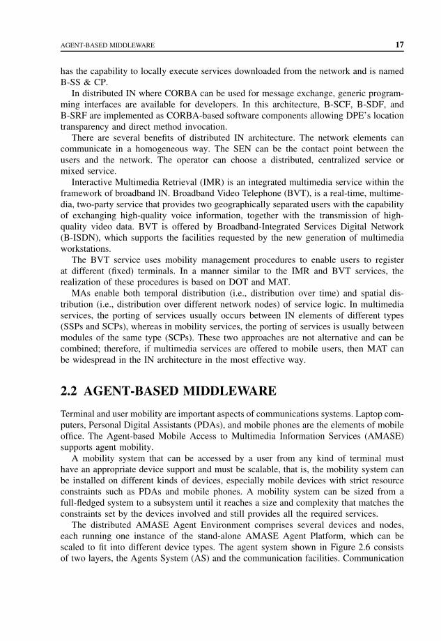
Terminal and user mobility are important aspects of communications systems. Laptop com-puters, Personal Digital Assistants (PDAs), and mobile phones are the elements of mobileoffice. The Agent-based Mobile Access to Multimedia Information Services (AMASE)supports agent mobility.
A mobility system that can be accessed by a user from any kind of terminal musthave an appropriate device support and must be scalable, that is, the mobility system canbe installed on different kinds of devices, especially mobile devices with strict resourceconstraints such as PDAs and mobile phones. A mobility system can be sized from afull-fledged system to a subsystem until it reaches a size and complexity that matches theconstraints set by the devices involved and still provides all the required services.
The distributed AMASE Agent Environment comprises several devices and nodes,each running one instance of the stand-alone AMASE Agent Platform, which can bescaled to fit into different device types. The agent system shown in Figure 2.6 consistsof two layers, the Agents System (AS) and the communication facilities. Communication

18 MOBILE AGENT-BASED SERVICE IMPLEMENTATION, MIDDLEWARE, AND CONFIGURATION
Administration API CF APIAgent API
CF API
AMASEAgent system
PersistentstorageAgent manager
Communication manager
MonitoringmoduleUser
manager
Fixed networks Cellular networks Wireless LANs
Communication Facility (CF)
Securitymanager
Resourcemanager
Agent soft-ware update
Systemstate
Configu-ration
Agentstate
Mobile and systemagent handling
Unique namingmodule
Eventhandling
Service trading Service center Remote service call
CF-servicehandler
Agentcommunicationprotocol handler
Agenttransport
protocol handler
Agentdirectory
protocol handler
Figure 2.6 Architecture of the AMASE system.
facilities provide access to a broad range of underlying networks and handle the roamingbetween different kinds of networks.
The AS layer provides a runtime environment for cooperative MAs. This layer allowsagents to migrate from one AS to another, to access services available in the network,and to communicate with other agents. The Service Center of the Agent System is afundamental component for mobile agent management and user mobility and is used forlocating and accessing services and agents.
The AMASE system and its supported agents are developed in Java. An agent systemlauncher supports loading a scaled version of the AS into a mobile device and executingit on different Java Virtual Machines (JVM). The launcher closely cooperates with a unitfor agent system software update allowing for upgrading the AS’s software at least atstart-up or upon request. An agent launcher is used for application allowing for moreconvenient and browser-like launching of agent-based applications by hiding all the Javaand agent system specifics.
The core of the AS is the Agent Manager (AM), allowing MAs access to the application-specific parts of the AS’s functionality via an agent API. The communication facilitiesare interfaced by AS’s Communication Manager (CM), and the communication facilitiesdetect connection to available networks and their special services. The CM establishesthe protocols for interagent communication, agent migration, and for accessing a ServiceCenter and its Agent Directory (AD) via its protocol handlers.

AGENT-BASED MIDDLEWARE 19
The Persistent Storage area is either located in the persistent memory area of theunderlying device, or on a magnetic medium. This area is needed to save agents and theagent system state and configuration.
The CM comprises user and security managers that establish a user management andallow for the enforcement of access policies. An additional resource manager providesinformation about device utilization, for example, memory or agent population. A com-ponent for dynamic updates of the agents’ software allows for versioning and updates ofagent classes.
The AM is responsible for controlling the agent population of the agent system. AMallows for launching and termination of agents and provides them with the functionalityneeded for migration, communication, service access, and so on. In AMASE environment,there are MAs and system agents. MAs are created by application and they can roamwithin the network. They are not allowed to access system resources for security reasons.Usually these agents interact with the user for an initial configuration before they arelaunched into the network. They allow the user to perform remote operations without aconstant network connection.
MAs and system agents are supported by the AS. System agents can access systemresources and become a mediator between the MAs and the system resources and theservices they need to access.
The AM cooperates with the user manager and the resource manager, which permitsthem to assign detailed access rights to agents. Both agent types are maintained separatelyby the AM, which supports a clearly defined type-dependent handling, for example, in caseof a shutdown. Agents are registered with the local AM, and MAs are also automaticallyregistered with the Service Center’s AD.
In Figure 2.6, the CM connects the entire agent system to the communication facilities,which connect a device to the available networks. The CM surveys preconfigured ports onsockets provided by the communication facilities to receive incoming messages. Agentscan be dispatched and handled by the AM. Each CM has access either to a local orremote router provided by the agent-related directories. This router helps CM to find andaddress the other agent systems. The CM is responsible for converting Java objects intobyte streams and is involved in synchronous communication, which requires temporalsuspension of agents.
CM and communication facilities optimize communication and connection handling.The protocols consider network and device characteristics, and Quality of Service (QoS)information. Connections are physically closed during timeouts but kept open virtually.These operations that are transparent to the agents save connection costs and supportdisconnected operations and user mobility. The following communications mechanismsare provided by using the agent system communication manager, its protocol handlers,and the underlying communication facilities:
• asynchronous one-way agent-to-agent messages;• synchronous two-way agent-to-agent messages based on Remote Procedure Call
mechanisms;

20 MOBILE AGENT-BASED SERVICE IMPLEMENTATION, MIDDLEWARE, AND CONFIGURATION
• blackboards for local agent communication within agent systems – a blackboard is adata area where agents can leave information that may be read and removed by otheragents under configurable access restrictions;
• postbox messages for specified agents; this is a message queue that belongs to asingle agent and which is located at a well-known location in the network that isknown to both the message senders and the postbox owner; the owner agent canonly read the box contents and remove the messages, and all other agents can dropmessages.
MAs are capable of migrating, which can occur at any time; thus, a mechanism isneeded to determine an agent’s current location. This mechanism is not necessary forasynchronous communication and communication based on blackboards and postboxes; itis inevitable for direct communication of agents. The Mobile Agent System Interoperabil-ity Facility (MASIF) specifies a Mobile Agent Facility (MAF) component MAFFinder,which is an abstract facility for mobile agent localization. MAFFinder is abstract becauseit does not specify how the agents are to be localized – only that a presence of suchfacility is required. Concepts for mobile agent localization include broadcast, forwarding,and directory service/home registry.
AMASE system introduces a Service Center based on a directory service using generalmobile agent execution cycle. MAs are restricted in their size and complexity owing tothe costs of agent migration. MAs use services to execute the tasks required. The agentscontact a facility in the agent system that provides a naming or trading service and passesinformation on the location of the requested services. This Service Center in AMASEsystem is based on the concept introduced by the Java Agent Environment (JAE).
AMASE system introduces a ticket concept to pass information to MAs while keepingthe actual migration and location information transparent. Mobile agent requesting aservice from the Service Center receives a ticket shown in Figure 2.7. By calling useSer-vice (ticket), the MA uses the service provided, migrating to the respective agent system ifit is not located in the same agent system. In addition to the information about home loca-tion, destination, and migration history, it is possible to store additional data in the ticketobject, for instance, departure time, maximum number of connection retries, and priorityinformation. The origin entry provides details about the creation and the starting point ofthe MA that is needed if the agent returns after having accomplished its task. Because ofthe user mobility and the disconnected operations, the originating device might be turnedoff and may become unreachable for the mobile agent. In this case, the permanent homeentry gives an alternative address. The permanent home is an agent system at the serviceprovider or the agent enabled home computer.
The architecture of the Service Center shown in Figure 2.8 introduces a new mechanismfor localizing MAs by using the AD. Whenever a MA requests a new service or migratesto another host, its position is updated in the Service Center. The agent location is storedin the AD. This is implemented as a Lightweight Directory Access Protocol (LDAP)server, with the Service Center holding an LDAP client for accessing the AD.
In this approach, a MA’s position is always known by the Service Center. The updateof the agent’s position is embedded in the agent migration process; a migration is notcompleted before the update has been executed. This way the MAs can always be tracked.

AGENT-BASED MIDDLEWARE 21
Destination:
Departure:
Departure Time:
Origin:
Permanent Home:
History:
amase.rwth.as4
amase.rwth.as3
30 min
amase.rwth.as_mobile0
amase.rwth.as0
amase.rwth.as3
amase.rwth.as1
amase.rwth.mobile0
Properties: IDENTITY
Property 1 UserIDRetryDelay SystemMaxRetry
8100 ms20 Domain
TICKET
Figure 2.7 An abstract ticket object.
LDAP AD
Otherservice centers
LDAPclient
Trader
Service center
SCmanagementand remote
servicecall
Localservices
Mobileagents
SC − API
Figure 2.8 Architecture of the service center.
There are no message bursts caused by agent localization. The AD concept allows a seam-less integration into the facilities required for localization services for mobile agent use.
The AMASE system allows the user to access individually configured services anddata from different kinds of terminals, keeping transparent the details of the configurationand underlying mechanisms. The user profiles are in the profile directory similar to the

22 MOBILE AGENT-BASED SERVICE IMPLEMENTATION, MIDDLEWARE, AND CONFIGURATION
AD. A user profile contains information about the user’s preferences and data, display andsecurity settings, and scheduling information and address books. The profile directory isa generic database for maintaining user information, which includes application-specificdata. Customized agents adapted to application-specific needs can be created on the devicethe user is currently deploying. The user can specify types of services to be used withouthaving to be aware of their location or current availability.
The mobility middleware system is presented in Figure 2.9. The mobile agent, equippedwith the service description and a specification of the preferred mechanism to returnresults, contacts the AD to localize the appropriate system agents that provide the requiredservices. The agent obtains the ticket and migrates to the appropriate system agents anduses their services. Once the results are generated, the profile directory is used. If the userspecified a type of terminal to deliver the results, the MA obtains the address from theprofile directory and returns the results via the respective telecommunication service. Onthe other hand, if the user does not specify a method for returning the results, the MAdecides which method to use. User and terminal profiles used with MAT create a flexibleand device-independent user mobility.
The users can become temporarily unreachable when the results are available. MAsallow the users to disconnect after specifying the service. If the method specified forreturning the result is an asynchronous message (e.g., e-mail, fax), no feedback is requiredby the MAs. On the other hand, if the agent’s execution depends on the user’s feedbackor if the return method is selected by the user after an initial notification, the MA can-not be terminated and must wait for user input to continue execution. The AMASEsystem introduces the kindergarten concept for an MA, which recognized that the tar-get user is currently unavailable, or, if the execution of the notification method failed
Service center(agent directory)
Service center(profile directory)
Telecommunicationservices
Mobile agent-kindergarten
Mobility middleware
(Fixed network) agent system
System agents
Contact user
(Mobile)agent system
3
6
5
4
2
1
Figure 2.9 The agent-based mobility middleware.

MOBILE AGENT-BASED SERVICE CONFIGURATION 23
2
Storage
Coordinator
Persistentstorage
Mobile agent kindergarten
1
Figure 2.10 The mobile agent kindergarten concept.
or timed out, to contact a kindergarten coordinator that checks if the system havinglast served the MA is capable of holding this agent until the user becomes available.In this case, the agent is suspended until further notice. The agent is instructed tomigrate to a host providing a kindergarten storage. This server suspends the MA andresumes it when the user reconnects. The MA can also be moved to persistent stor-age until being resumed, which allows for managing a large number of MAs. Thekindergarten concept shown in Figure 2.10 provides a mechanism for handling MAsbelonging to disconnected users and forms the basis of mobility support deploying userand terminal profiles.
2.3 MOBILE AGENT-BASED SERVICECONFIGURATION
MAT allows for object migration and supports Virtual Home Environment (VHE) inthe Universal Mobile Telecommunications System (UMTS). VHE uses MAs in servicesubscription and configuration.
UMTS supports QoS, the Personal Communication Support (PCS), and VHE. TheVHE allows for service mobility and roaming for the user, which carries subscribed andcustomized services while roaming. During the registration procedure, the VHE enablesthe visited network to obtain the information about the user’s service provider, the user’spersonalized service profile, and the identification about service capabilities to executespecific services.
The VHE architecture shown in Figure 2.11 can be viewed as middleware layer thathides from the user the concrete network capabilities and differences in user and providersystem capabilities. Service intelligence can be located inside the network within theService Control and Mobility Management Platform (SC & MMP) or outside the networkwithin the Universal Service Identification Module (USIM) of the end system. Serviceadaptation and media conversion is needed to cope with the diversity of end systemssupporting personal mobility and QoS variations of different ANs supporting terminal

24 MOBILE AGENT-BASED SERVICE IMPLEMENTATION, MIDDLEWARE, AND CONFIGURATION
Providersystems
Endsystems
Applications (subscribed services)
Virtual home environment
Transport networks
Figure 2.11 Virtual home environment.
mobility. The enhancements of service control intelligence during service execution anddynamic subscription of a new third-party services should be allowed in the system.
The UMTS environment shown in Figure 2.12 consists of a terminal, the AN, theSC & MMP, and the third-party service provider. A user registers at the terminal thatpresents services to the user. The user’s identification and authentication is handled bythe UMTS Subscriber Identity Module (USIM). The network access of the terminal ismanaged by the access network. Fixed or mobile terminals are linked by the AN to theSC & MMP. The SC & MMP contains service logic and is responsible for the mobilitymanagement. Third-party service provides support supplementary services. A third-partyservice provider has a connection to one or more SC & MMPs and does not have its ownmobility management facilities.
A middleware layer is introduced in UMTS architecture in Figure 2.13. The middlewareconsists of Distributed Agent Environment (DAE), for example, Grasshopper, which isbuilt on the top of DPE, for example, CORBA, and spans all potential end user systemsand provider systems. The nodes provide agent environments through middleware system
SC&MMP
SC&MMP
ANAN
Mobile station
USIM
SC&MMP
Third party SP
Third party SP
Third party SP
End user system Home provider system Other provider system Third party provider system
Figure 2.12 The main components of the third-generation mobile communication system.

MOBILE AGENT-BASED SERVICE CONFIGURATION 25
ANMobile station
USIM
Visited MSC Gateway MSC Third party service provider
AgencyAgencyAgency
Agents
DPE/DAE
Core network
Agency
Figure 2.13 The distributed agent environment spanning across UMTS end user andprovider systems.
to enable downloading and migration of MAs. MAs contain intelligence related to mobilitymanagement and service control (VHE control) and the end user application between theinvolved system nodes, including the Mobile Stations (MSs).
In agent-based UMTS, a VHE-agent realizes the VHE concept; a Service Agent (SA)represents a provided service; a Terminal Agent (TA) allows the terminal to inform theprovider system about its capabilities; and a Provider Agent (PA) realizes a trader withinthe provider system, which manages all supported services (SA), that is, maintains anoverview of all available services within the provider domain.
The VHE allows individually subscribed and customized services to follow their associ-ated users wherever they roam. The VHE-agent follows the user to the domain to whichthe user is roaming. At every domain, the VHE-agent provides the user’s subscribedservices and configurations.
Agencies in the MS allow dynamic distribution of mobility management and servicecontrol intelligence to be downloaded dynamically from the MS into the (visited) providersystem and from the (visited) provider system onto the MS, to be distributed within oneprovider system at the most appropriate location and to be distributed between differentprovider systems. The end systems through the USIM can take an active part in mobilitymanagement and service control.
The PA residing in every provider domain contains the knowledge of all servicesprovided by this domain. The PA is designed as a trader in MASIF. The PA is theinitial contact point of the VHE-agent after the user is roamed to a new domain. ThePA is designated as a stationary agent since its task makes the migration of this agentnot necessary.
The SAs are located within the provider domain, or at the third-party service providerdomains, or at the user’s terminal. The Converter Agents (CAs) at the provider agency areresponsible for converting incoming and outgoing calls on the basis of user and terminalrequirements. This allows for support of services on terminals that cannot originally

26 MOBILE AGENT-BASED SERVICE IMPLEMENTATION, MIDDLEWARE, AND CONFIGURATION
USIM agency
Service agents
Service provider agency
Third party service agents
Converter agents
SA
SA SA
PAVHE
TA
Outgoing
(access)
Incoming
Figure 2.14 Basic agent relationships.
present the service such as reading out a fax or e-mail on a telephone. The knowledgeof the terminal capabilities is maintained by the TA. Different types of agents and theircommunication relationships are shown in Figure 2.14.
The VHE-agent can migrate from the provider domain from which the user comes tothe provider domain to which the user is roaming. Another possibility is to store a majorcopy of the VHE-agent within the home service provider domain. Whenever the userroams to a new provider domain, a copy of the VHE-agent migrates to this domain. TheVHE-agent can also be stored on the terminal agency. The VHE-agent migrates from theterminal agency to the provider agency when the user roams to a new domain.
Dynamic subscription allows a user to subscribe to and to unsubscribe services. Thesubscription component presents the entire set of provided services to the user. Theinformation can be retrieved during the registration procedure after the user roamed to anew provider, and the subscription component requests the provider to get informationabout provided services. The services of a new provider can also be concatenated to theservice list that is stored by the VHE. The network can provide a roaming broker that canbe contacted by the subscription component to get the information about service providers.
The abstract service subscription is present at the provider where the user roams.The user registers at the new provider, and the VHE-agent contacts the PA to receive asubscription interface to process the VHE request. The PA finds an SA that correspondsto the abstract service description. The PA returns a reference to the existing SA thatmatches with the service description. If there is no SA matching service description, thePA finds a corresponding agent at different service providers. The PA explores possibilitiesillustrated in Figure 2.15. The current service provider can contact other service providers,or a roaming broker can be used, or the home service provider can provide a referenceto the service agent.
The User Interface Agent (UIA) is responsible for the presentation of the SA atthe user’s terminal. The UIA provides terminal-dependent service presentation capabil-ities. The same service can be represented by many UIAs for terminals with differentcapabilities. The VHE-agent decides which UIA download to the terminal as shown inFigure 2.16. The VHE-agent contacts the TA, which resides on the terminal agency, that

MOBILE AGENT-BASED SERVICE CONFIGURATION 27
Third party service provider region
Third party SP agency
Roaming Broker Agency
Place
SAPA
RBA
2 2
32
PA
TA VHESA
SA
Place Place
MSC agencyUSIM agencyMobile station
1
1
1 - Provider agent tries to find a serviceagent in its own domain and with capabilitiesthat can be presented at the terminal ofthe user2 - Provider agent contacts the RoamingBroker (RB). The RB tries to find a matchingservice agent3 - Provider agent contacts the homeservice provider to get access to theservice agent
Home service provider region
Visited service provider region
PA
Place Place
Home service provider agency
SA
SA
Figure 2.15 Service access strategies.
1
4
2 3
Service provider region
TA
Place
SAPA
VHE
Place
MSC agency
USIM agency
Mobile station
1- VHE-agent requests the Terminal Agent toget properties of the terminal. This informationwill be sent by the TA to the VHE-agent.2 - The VHE-agent will request the provideragent.3 - To find a corresponding UIA.4 - If a UIA was found, it will be downloaded tothe terminal agency.
Figure 2.16 The UIA selection procedure.

28 MOBILE AGENT-BASED SERVICE IMPLEMENTATION, MIDDLEWARE, AND CONFIGURATION
is, mobile station. This TA is device dependent and contains technical information aboutthe terminal. The VHE-agent requests the TA to get this information. The returned val-ues are used by the VHE-agent to find a corresponding UIA. The service subscriptionprocedure is used to locate the UIA.
2.4 MOBILE AGENT IMPLEMENTATION
MAs can be implemented in Java programming language. Additional features and mech-anisms supported and envisioned in Jini programming language allow for implementationof mobile devices in practical systems.
The Jini vision introduced by Edwards allows for devices and software services to worktogether in a simple, fast, and reliable manner. The requirements for devices and softwarespecify robust software infrastructure developed to support reliable systems. The devicesmust be easy to use and administer, and should work instantly after being connected. Thesoftware systems must be evolvable, and software services and devices should permit theiruse without reconfiguration of the network. These devices form spontaneous communitieswithin dynamic networking.
Mobile code is used in several structures to support mobile applications. In Java pro-gramming language, applets are used for small applications to be installed automaticallywherever they are needed and removed when their users do not need them. In the agentparadigm, small, autonomous bits of code travel to search for desired data. The mobilecode is used for performance and autonomy. Agents can provide a better performanceas the code moves closer to data in the network. Agent autonomy allows the user tolog off or shut down the machine, and the agent that left the originator computer cancontinue to run even if the originator disconnects. Java RMI allows for building variousdistributed systems and can be used for automatic application installation or for buildingagent-based systems. Mobile code in RMI is used for object-oriented networked systemsand it supports evolvable implementations of remote objects and new implementations ofparameter and return types. Jini uses mobile code to achieve maintenance, evolvability,and ease of administration for networked devices and services. Jini is layered atop RMI,allowing all the benefits of mobile code to be used by programs in Jini.
Jini supports spontaneously created self-healing communities of services, and it isbased on the concepts of discovery, lookup, leasing, remote events, and transactions.
Jini uses discovery protocols to find the available lookup services. The MulticastRequest Protocol is used to find the active lookup services after an application or servicebecomes initiated. Lookup services announce their existence in the system by using theMulticast Announcement Protocol. An application or service talks to the lookup serviceby using the Unicast Discovery Protocol.
The lookup service is a process that has semantic information about available services.The service items have proxy objects and attributes describing these services.
Jini concept of leasing allows the resource to be loaned to a customer for a fixed periodof time rather than granting access to a resource for an unlimited amount of time. Thisensures that the communities of services are stable, self-healing, and resilient to failures,errors, and crashes.

PROBLEMS TO CHAPTER 2 29
Jini uses remote events to allow services to notify each other about the changes intheir state. These are messages sent as asynchronous notifications directly to a softwarecomponent and handled outside the normal flow of control of the component.
Computations involving multiple services reach safe and known state by using transac-tions in Jini. Transactions provide atomicity, consistency, isolation, and durability to datamanipulations. All the operations under transactions are executed as an atomic operation.Transactions ensure state consistency after completion. Transactions are isolated duringexecution; they do not affect one another until completion. Transaction durability makesthe changes permanent.
2.5 SUMMARY
MAT uses the capabilities provided by machine-independent, interpreted languages like Javato deploy a framework in which applications can roam between network nodes maintainingtheir execution status. MAT platforms are often based on a CORBA DPE layer, which allowsdistributed applications to dynamically reconfigure their layout according, for instance, toprocessing needs. This way certain MAs may have a CORBA interface enabling them toexploit the facilities offered by the distributed objects communication infrastructure.
The introduction of DOT and MAT at the service design and deployment level allowsfor reusability for easy and rapid deployment of services, extensibility towards new andupdated services, and flexibility of service design.
The AS layer provides a runtime environment for cooperative MAs. This layer allowsagents to migrate from one AS to another, to access services available in the network, andto communicate with other agents. The Service Center of Agent System is a fundamentalcomponent for mobile agent management and user mobility and is used for locating andaccessing services and agents.
MAT allows for object migration and supports VHE in the UMTS. VHE uses MAs inservice subscription and configuration.
The UMTS environment consists of a terminal, the AN, the SC & MMP, and thethird-party service provider.
In agent-based UMTS, a VHE-agent realizes the VHE concept; an SA represents a pro-vided service; a TA allows the terminal to inform the provider system about its capabilities;and a PA realizes a trader within the provider system, which manages all supported services(SA), that is, maintains an overview of all available services within the provider domain.
PROBLEMS TO CHAPTER 2
Mobile agent-based service implementation, middleware, and configuration
Learning objectives
After completing this chapter, you are able to
• demonstrate an understanding of distributed object technology;• discuss what is meant by intelligent agents;

30 MOBILE AGENT-BASED SERVICE IMPLEMENTATION, MIDDLEWARE, AND CONFIGURATION
• demonstrate an understanding of agent-based service implementation;• explain how to handle service requests;• explain temporal and spatial distribution of service logic;• discuss multimedia services;• demonstrate an understanding of a mobility system;• explain what agent system, agent manager, and communication manager are;• explain mobility middleware system;• demonstrate an understanding of the Universal Mobile Telecommunications System
(UMTS);• discuss what an agent-based UMTS is;• demonstrate an understanding of the VHE concept;• explain how the VHE-agent migrates in the system;• explain dynamic subscription of services;• demonstrate an understanding of mobile agent implementation in Java program-
ming language;• demonstrate an understanding of mobile agent implementation in Jini program-
ming language.
Practice problems
2.1: What is the role of DPE in DOT?2.2: What are the functions of Intelligent and Mobile Agents?2.3: What distribution of service logic is enabled by Mobile Agents?2.4: What are the requirements for a mobility system?2.5: What is the role of the Agent System layer?2.6: Where is the Persistent Storage located and why is it needed?2.7: What is supported by the UMTS?2.8: What are the elements of the UMTS environment?2.9: How is the VHE concept realized in agent-based UMTS?
2.10: What is the role of dynamic subscription?2.11: What is the role of the User Interface Agent (UIA)?2.12: What are applets used for in Java programming language?2.13: What is the concept of Jini programming language?
Practice solutions
2.1: DOT provides a DPE to enable designers to create object-oriented distributed appli-cations, which are not necessarily aware of the physical layout of the underlyingnetwork structure hidden by platform services.
2.2: Intelligent Agents have the ability to learn and react. MAs can migrate betweendifferent hosts, execute certain tasks, and collaborate with other agents.
2.3: MAs enable both temporal distribution (i.e., distribution over time) and spatialdistribution (i.e., distribution over different network nodes) of service logic.
2.4: Mobility system that can be accessed by a user from any kind of terminal musthave an appropriate device support and must be scalable, that is, the mobility system

PROBLEMS TO CHAPTER 2 31
can be installed on different kinds of devices, especially mobile devices with strictresource constraints such as PDAs and mobile phones. A mobility system can besized from a full-fledged system to a subsystem until it reaches a size and complexitythat matches the constraints set by the devices involved and still provides all therequired services.
2.5: The AS layer provides a runtime environment for cooperative MAs. This layerallows agents to migrate from one AS to another, to access services available inthe network, and to communicate with other agents. The Service Center of AS is afundamental component for mobile agent management and user mobility, and it isused for locating and accessing services and agents.
2.6: The Persistent Storage area is either located in the persistent memory area of theunderlying device or on a magnetic medium. This area is needed to save agentsand the agent system state and configuration.
2.7: UMTS supports QoS, the PCS, and VHE.2.8: The UMTS environment consists of a terminal, the AN, the SC & MMP, and the
third-party service provider.2.9: In agent-based UMTS, a VHE-agent realizes the VHE concept; an SA represents a
provided service; a TA allows the terminal to inform the provider system about itscapabilities; and a PA realizes a trader within the provider system, which managesall supported services (SA), that is, maintains an overview of all available serviceswithin the provider domain.
2.10: Dynamic subscription allows a user to subscribe to and to unsubscribe services.The subscription component presents the entire set of provided services to the user.
2.11: The UIA is responsible for the presentation of the SA at the user’s terminal. TheUIA provides terminal-dependent service presentation capabilities. The same servicecan be represented by many UIAs for terminals with different capabilities.
2.12: In Java programming language, applets are used for small applications to be installedautomatically wherever they are needed, and removed when their users do notneed them.
2.13: Jini supports spontaneously created self-healing communities of services and isbased on the concepts of discovery, lookup, leasing, remote events, and transactions.


3
Wireless local area networks
Virtual LANs provide support for workgroups that share the same servers and otherresources over the network. A flexible broadcast scope for workgroups is based onLayer 3 (network). This solution uses multicast addressing, mobility support, and theDynamic Host Configuration Protocol (DHCP) for the IP. The hosts in the network areconnected to routers via point-to-point connections. The features used are included inthe IPv6 (Internet Protocol version 6) protocol stacks. Security can be achieved by usingauthentication and encryption mechanisms for the IP. Flexible broadcast can be achievedthrough enhancements to the IPv6 protocol stack and a DHCP extension for workgroups.
Orthogonal Frequency Division Multiplex (OFDM) is based on a mathematical conceptcalled Fast Fourier Transform (FFT), which allows individual channels to maintain theirorthogonality or distance to adjacent channels. This technique allows data symbols tobe reliably extracted and multiple subchannels to overlap in the frequency domain forincreased spectral efficiency. The IEEE 802.11 standards group chose OFDM modulationfor wireless LANs operating at bit rates up to 54 Mb s−1 at 5 GHz.
Wideband Code Division Multiple Access (WCDMA) uses 5 MHz channels and sup-ports circuit and packet data access at 384 kb s−1 nominal data rates for macrocellular wire-less access. WCDMA provides simultaneous voice and data services. WCDMA is the radiointerface technology for Universal Mobile Telecommunications System (UMTS) networks.
Dynamic Packet Assignment (DPA) is based on properties of an OFDM physical layer.DPA reassigns transmission resources on a packet-by-packet basis using high-speed receivermeasurements. OFDM has orthogonal subchannels well defined in time–frequency grids,and has the ability to rapidly measure interference or path loss parameters in parallel on allcandidate channels, either directly or on the basis of pilot tones.
3.1 VIRTUAL LANs
Virtual LANs provide support for workgroups. A LAN consists of one or more LANsegments, and hosts on the same LAN segment can communicate directly through Layer 2(link layer) without a router between them. These hosts share the same Layer 3 (network
Mobile Telecommunications Protocols For Data Networks. Anna HacCopyright 2003 John Wiley & Sons, Ltd.
ISBN: 0-470-85056-6
34 WIRELESS LOCAL AREA NETWORKS
layer) subnet address, and communication between the hosts of one LAN segment remainsin this segment. Thus Layer 3 (network layer) subnet address forms a broadcast scopethat contains all hosts on the LAN segment.
The workgroups are groups of hosts sharing the same servers and other resourcesover the network. The hosts of a workgroup are attached to the same LAN segment, andbroadcasting can be used for server detection, name resolution, and name reservation.
In a traditional LAN the broadcast scope is limited to one LAN segment. Switched LANsuse a switch infrastructure to connect several LAN segments over high-speed backbones.Switched LANs share the Layer 3 (network layer) subnet address, but offer an increasedperformance compared to traditional LANs, since not all hosts of a switched LAN have toshare the bandwidth of the same LAN segment. LAN segments connected over backbonesallow for distribution of hosts over larger areas than that covered by a single LAN segment.
Traditional switched LANs require a separate switch infrastructure for each workgroupin the environment with several different workgroups using different LAN segments.Virtual LANs are switched LANs using software configurable switch infrastructure. Thisallows for creating several different broadcast scopes over the same switch infrastructureand for easily changing the workgroup membership of individual LAN segments.
The disadvantage of virtual LANs is that a switch infrastructure is needed and admin-istration includes Layers 2 and 3 (link and network). A desirable solution involves onlyLayer 3 (network) and does not require special hardware.
Kurz et al. propose a flexible broadcast scope for workgroups based on Layer 3 (net-work). This solution uses multicast addressing, mobility support, and the DHCP for theIP. The hosts in the network are connected to routers via point-to-point connections. Thefeatures used are included in the IPv6 protocol stacks. Security can be achieved by usingauthentication and encryption mechanisms for the IP. Flexible broadcast can be achievedthrough enhancements to the IPv6 protocol stack and a DHCP extension for workgroups.
In IPv6, a special address range is reserved for multicast addresses for each scope, anda multicast is received only by those hosts in this scope that are configured to listen tothis specific multicast address. To address all hosts in a certain scope with a multicast, themulticast must be made to the predefined all-nodes address, to which all hosts must listen.When existing software using IPv4 (Internet Protocol version 4) is migrated to IPv6, theIPv4 broadcasts are changed to multicasts to the all-nodes address, as this is the simplestway to maintain the complete functionality of the software.
IPv6 multicasting can be used to form the broadcast scope of a workgroup. Theworkgroup is the multicast group, whose hosts listen to the same multicast address, theworkgroup address. A host can listen to several multicast addresses at the same time andcan be a member of several workgroups.
Multicasting exists optionally for IPv4 and is limited by a maximum of hops. Themulticast in IPv6 is limited by its scope, which is the address range.
In a virtual LAN, the workgroup membership of a host is determined by configurationof the switches. Kurz et al. propose that a host has to determine its workgroups andtheir corresponding multicast addresses. Different workgroups are separated in Layer 3(network) since each host has the possibility to address a specified subset of hosts of thenetwork using multicasting. All hosts can be connected directly to the routers, and themembers of different workgroups can share the same LAN segment.

VIRTUAL LANs 35
The administration of the workgroups is designed by storing the information abouthosts and their workgroups in a central database in a DHCP server. The information isdistributed by using the Dynamic Host Configuration Protocol version 6 (DHCPv6).
3.1.1 Workgroup management
In a workgroup address configuration, the host sends a DHCP Request with a WorkgroupAddress Extension to the DHCP Server. The DHCP Server replies with a WorkgroupAddress Extension containing all workgroup addresses assigned to this host. After receiv-ing the workgroup addresses, the host sends the Internet Control Message Protocolversion 6 (ICMPv6) Group Membership Report to each of its workgroup addresses toinform the multicast routers about its new membership in these multicast groups.
After learning its workgroup addresses, the host has to configure its interfaces to listento these multicast addresses. The host has to change all outgoing multicasts to the all-nodes address (which are equivalent to IPv4 broadcasts) to multicast to the workgroupaddress of the host. This can be done by changing the IPv6 stack to intercept all outgoingmulticasts to the all-nodes address and to change this address to the workgroup addressesof the host. If the host is a member of several workgroups, the multicast has to be sentto all workgroup addresses of the host.
The purpose of DHCP is to provide hosts with addresses and other configurationinformation. DHCP delivers the configuration data in extensions that are embedded inrequest, reply, or reconfigure messages. The request message is used by the client torequest configuration data from the server, and the reply message is used by the server toreturn the requested information to the client. If there is a change in the DHCP database,the server uses the reconfigure message to notify the client about the change and to startthe new request reply cycle.
Kurz et al. introduce a DHCP Workgroup Address Extension to deliver workgroupaddresses to the host. In a DHCP Request the client must set the workgroup count to zero,must not specify any workgroup addresses, and must specify its node name. In a DHCPReply the server must set the workgroup count to the number of workgroup addressesexisting for this client, include all workgroup addresses existing for this client, and usethe client’s node name. In a DHCP Reconfigure the server must set the workgroup countto zero, must not specify any workgroup addresses, and must use the client’s node name.
Mobile hosts can be the members of workgroups. The Internet draft Mobility Supportin IPv6 proposes that a mobile host attached to a network segment other than its homesegment continues to keep its home address on the home segment and forms a globalcare-of address for its new location. The binding update options included in IPv6 packetsare used to inform correspondent hosts as well as the home agent, a router that is on thesame segment as the home address of the mobile host, about its new care-of address. Afterthe home agent is informed about the new care-of address of the mobile host, the homeagent receives packets on the home segment addressed to the mobile host and tunnelsthem to the care-of address of the mobile host.
Kurz et al. propose enhancements to the Internet draft Mobility Support in IPv6 for amobile workgroup member to send or receive multicast packets from its home networkand to participate in the multicast traffic of its group. If a mobile host leaves the scope

36 WIRELESS LOCAL AREA NETWORKS
of a multicast group it joined, the home agent must forward packets sent to the homeaddress of the mobile host and also all packets sent to the concerned multicast address.The mobile host has to be able to send packets to the multicast address of its workgroup,even though it is outside the scope of this address. This can only be done by tunnelingthe packets to a host inside the scope of the multicast address and resending them fromthat host. Since the home agent is on the segment associated with the home address ofthe mobile host, the task of resending multicasts of a mobile host can also be taken overby the home agent.
The Internet draft Mobility Support in IPv6 proposes a binding update option, whichis used to notify the home agent and other hosts about a new care-of address of a mobilehost. The original home link local address of the mobile host has to be specified in thesource address field in the IP header of the packet containing the binding update option.It can also be specified in the home link local address field in the binding update option,but a multicast address cannot be specified this way. Kurz et al. introduce an optionalfield for a multicast address in the binding update option to inform the home agent aboutworkgroup addresses to which the mobile host listens. A field for the workgroup addressis used to indicate that there is a multicast group address specified in the option.
3.1.2 Multicast groups
A mobile host that left the scope of one of its multicast groups sends a binding updateoption to its home agent to inform it about the new care-of address. A mobile host hasto specify its multicast group address in the binding update option. If the mobile host isa member of several multicast groups, it has to send a binding update option for each ofits multicast groups.
A home agent notified by a binding update option about a multicast address for amobile host must join this multicast group and handle packets with this multicast addressin the destination address field in the same way as the packets with the home addressof the mobile node in this field. The mobile host must treat a received encapsulatedmulticast packet in the same way as the packet received directly. The mobile host mustnot send a binding update option to the address specified in the source address field ofan encapsulated multicast packet.
When sending a multicast packet to its multicast group, the mobile host has to use itshome address in the source address field of the multicast packet and tunnel this packet toits home agent. When a home agent receives an encapsulated multicast packet in whichthe source address field is the same as the home address of a mobile host served by it,the home agent has to act like a router, receiving this multicast packet from the homesegment of the mobile host and additionally forwarding it to the home segment of themobile host.
This way of providing mobile workgroup members with the possibility to leave thescope of the multicast address has a drawback that it may not scale well in the case ofbroadcast intensive workgroup protocol stacks, since all the broadcasting traffic, whichwas intended to remain in the limited area, has to be forwarded to the mobile node.If many workgroup members use the possibility of global mobility, there is a risk ofoverloading the Internet with workgroup broadcasting traffic.

WIDEBAND WIRELESS LOCAL ACCESS 37
Virtual LANs enhance the flexibility of the available software without requiring anychanges to the software. The software adapted in the new IPv6 address space in the futurecan be changed to use the all-nodes multicast address instead of IPv4 broadcast. Whenusing IPv6 multicasting, no special Virtual LAN switches and protocols are required, andonly small enhancements to IPv6 and DHCP are necessary. This solution can offer aviable software alternative to Virtual LANs when faster routers are available.
3.2 WIDEBAND WIRELESS LOCAL ACCESS3.2.1 Wideband wireless data access based on OFDM and dynamic
packet assignment
OFDM has been shown to be effective for digital audio and digital video broadcastingat multimegabit rates. The IEEE 802.11 standards group chose OFDM modulation forWireless LANs operating at bit rates up to 54 Mb s−1 at 5 GHz.
OFDM has been widely used in broadcast systems, for example, for Digital AudioBroadcasting (DAB) and for Digital Video Broadcasting (DVB). OFDM was selected forthese systems primarily because of its high spectral efficiency and multipath tolerance.OFDM transmits data as a set of parallel low bandwidth (from 100 Hz to 50 kHz) carriers.The frequency spacing between the carriers is a reciprocal of the useful symbol period. Theresulting carriers are orthogonal to each other, provided correct time windowing is used atthe receiver. The carriers are independent of each other even though their spectra overlap.OFDM can be easily generated using an Inverse Fast Fourier Transform (IFFT) and it canbe received using an FFT. High data rate systems are achieved by using a large number ofcarriers (i.e., 2000–8000 as used in DVB). OFDM allows for a high spectral efficiency asthe carrier power, and modulation scheme can be individually controlled for each carrier.
Chuang and Sollenberger proposed OFDM modulation combined with DPA, with wide-band 5-MHz channels for high-speed packet data wireless access in macrocellular andmicrocellular environments, supporting bit rates ranging from 2 to 10 Mb s−1. OFDM canlargely eliminate the effects of intersymbol interference for high-speed transmission ratesin very dispersive environments. OFDM supports interference suppression and space–timecoding to enhance efficiency. DPA supports spectrum efficiency and high-rate data access.
Chuang and Sollenberger proposed DPA based on properties of an OFDM physicallayer. DPA reassigns transmission resources on a packet-by-packet basis using high-speed receiver measurements. OFDM has orthogonal subchannels well defined in time–frequency grids and has the ability to rapidly measure interference or path loss parametersin parallel on all candidate channels, either directly or on the basis of pilot tones.
The protocol for a downlink comprises of four steps:
1. A packet page from a base station to a terminal.2. Rapid measurements of resource usage by a terminal using the parallelism of an
OFDM receiver.3. A short report from the terminal to the base station of the potential transmission quality
associated with each radio resource.4. Selection of resources by the base and transmission of the data.

38 WIRELESS LOCAL AREA NETWORKS
22 packet-data channels3 control channels
528
tone
div
ided
into
22
24-t
one
clus
tersx
x
x
Freq
uenc
y
Ass
ignm
ent c
hann
el
Pag
ing
chan
nel
Pilo
t cha
nnel
• • • • • • • •
24 OFDM blocks 104 OFDM blocks in 8 slots
Figure 3.1 Division of radio resources in time and frequency domains to allow DPA for highpeak-rate data services.
The frame structures of adjacent Base Stations (BSs) are staggered in time; the neigh-boring BSs sequentially perform the four different DPA functions with a predeterminedrotational schedule. This avoids collision of channel assignments. This protocol pro-vides a basis for admission control and bit rate adaptation based on measured signalquality.
Figure 3.1 shows radio resources allocation scheme in which 528 subchannels, each of4.224 MHz, are organized into 22 clusters of 24 subchannels of 192 kHz each in frequencyand 8 time slots of 13 OFDM blocks each within a 20 ms frame of 128 blocks. This allowsflexibility in channel assignment while providing 24 blocks of control overhead to performthe DPA procedures. Each tone cluster contains 22 individual modulation tones plus twoguard tones. There are 13 OFDM blocks in each traffic slot and two blocks are usedas overhead – a leading block for synchronization and a trailing block as guard time forseparating consecutive time slots. A radio resource is associated with a frequency hoppingpattern in which the packets are transmitted using eight different tone clusters in each ofthe eight traffic slots. Coding across eight traffic slots for user data exploits frequencydiversity, which gives sufficient coding gain for performance enhancement in the fadingchannel. This arrangement supports 22 resources in frequency that can be assigned byDPA. Considering overhead for OFDM block guard time, synchronization, slot separation,and DPA control, a peak data rate of 2.1296 (3.3792 × 22/24 × 11/13 × 104/128) Mb s−1
is available for packet data services using all 22 radio resources, each of 96.8 kb s−1.Frame structure is shown in Figure 3.2 for downlink DPA. The uplink structure is sim-
ilar but the control functions are slightly different. In each frame the control channels forboth the uplink and downlink jointly perform the four DPA procedures sequentially witha predetermined staggered schedule among adjacent BSs. The control channel overhead isincluded to allow three sectors to perform DPA at different time periods. This allows inter-ference reduction and additional Signal to Interference Ratio (SIR) enhancement for thecontrol information. Spectrum reuse is achieved for traffic channels through interferenceavoidance using DPA to avoid slots causing potential interference. The frame structure
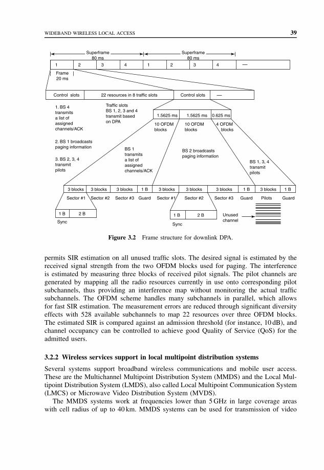
WIDEBAND WIRELESS LOCAL ACCESS 39
0.625 ms1.5625 ms1.5625 ms
10 OFDMblocks
10 OFDMblocks
BS 2 broadcastspaging information
BS 1transmitsa list of assignedchannels/ACK
BS 1, 3, 4transmitpilots
Traffic slotsBS 1, 2, 3 and 4transmit basedon DPA
1. BS 4transmitsa list of assignedchannels/ACK
2. BS 1 broadcastspaging information
3. BS 2, 3, 4transmitpilots
3 blocks 3 blocks 3 blocks 3 blocks 3 blocks 3 blocks 3 blocks1 B 1 B
GuardGuardGuard Sector #3Sector #2Sector #1Sector #3Sector #2Sector #1
1 B 1 B 2 B
Sync
2 B
Sync
Pilots
1 B
4 OFDM blocks
1 2
Frame20 ms
Control slots 22 resources in 8 traffic slots Control slots
3 4 1 2 3 4
Unusedchannel
Superframe80 ms
Superframe80 ms
Figure 3.2 Frame structure for downlink DPA.
permits SIR estimation on all unused traffic slots. The desired signal is estimated by thereceived signal strength from the two OFDM blocks used for paging. The interferenceis estimated by measuring three blocks of received pilot signals. The pilot channels aregenerated by mapping all the radio resources currently in use onto corresponding pilotsubchannels, thus providing an interference map without monitoring the actual trafficsubchannels. The OFDM scheme handles many subchannels in parallel, which allowsfor fast SIR estimation. The measurement errors are reduced through significant diversityeffects with 528 available subchannels to map 22 resources over three OFDM blocks.The estimated SIR is compared against an admission threshold (for instance, 10 dB), andchannel occupancy can be controlled to achieve good Quality of Service (QoS) for theadmitted users.
3.2.2 Wireless services support in local multipoint distribution systems
Several systems support broadband wireless communications and mobile user access.These are the Multichannel Multipoint Distribution System (MMDS) and the Local Mul-tipoint Distribution System (LMDS), also called Local Multipoint Communication System(LMCS) or Microwave Video Distribution System (MVDS).
The MMDS systems work at frequencies lower than 5 GHz in large coverage areaswith cell radius of up to 40 km. MMDS systems can be used for transmission of video

40 WIRELESS LOCAL AREA NETWORKS
and broadcast services in rural areas. Because of the large cell size, MMDS systems donot perform well for bidirectional communication that integrates a return channel.
The LMDS systems work with higher frequencies where a larger frequency spectrumis available than that in the MMDS systems. The coverage for LMDS systems involvessmaller cells of up to 5 km radius and requires repeaters to be placed in a Line Of Sight(LOS) configuration. This local coverage with a large available bandwidth makes LMDSsystems suitable for interactive multimedia services distribution.
Broadband wireless access is based on the Two-Layer Network (TLN) concept inwhich subscribers are grouped into microcells, which are embedded into a macrocell.The microcells coverage uses local repeaters operating at 5.8 GHz fed by a BS through40 GHz links. OFDM modulation is used to allow the reception with plug-free receiverslocated inside the buildings. A 40 GHz band fixed receiver provides a rooftop antenna inLOS with the transmitting antenna. This LMDS system provides an integrated wirelessreturn channel.
The LMDS architecture uses co-sited BS equipment. The indoor digital equipmentconnects to the network infrastructure, and the outdoor microwave equipment mountedon the rooftop is housed at the same location. The Radio Frequency (RF) planning usesmultiple sector microwave systems, where the cell site coverage is divided into 4, 8, 12,16, or 24 sectors.
The user accesses the network through Hybrid Fiber Radio (HFR), Radio To TheBuilding (RTTB) and Radio To The Curb (RTTC). In HFR, a Radio Frequency Unit (RFU)carries out signal down conversion from RF frequency to the intermediate frequency.The signal feeds the Radio Termination (RT) of each user through a bus link. In RTTBarchitecture the signal feeds the user Network Termination (NT) through point-to-pointcable links. In RTTC the RFU is placed in a common outdoor unit and is shared amongseveral buildings.
In high-population cities, LMDS systems can be used as LOS propagation channels athigh frequencies. LOS operation is inherently inflexible even for low mobility services.On the other hand, the available bandwidth for LMDS frequencies exceeds 1 GHz, makingit a very desirable transmission method. The frequency bands assigned to MMDS andLMDS are included in the frequency bands allocated for fixed services. The exceptionis the 40.5–42.5-GHz band allocated for MVDS systems. The 28-GHz channel is notgenerally open in several countries. This is why the 40-GHz technology is considered.However, the baseband system is designed to be compatible with interchangeable RFsystem (5/17/28/40 GHz).
LMDS is a stand-alone system providing wireless multimedia and Internet services,and it can be used as the support infrastructure for other wireless multimedia services, forexample, UMTS, wireless LAN, and Broadband Radio Access Network (BRAN), whichprovide a high-speed digital connection to the user.
Sukuvaara et al. proposed a two-layer 40-GHz LMDS system providing wireless inter-active cellular television and multimedia network. The first layer, a macrocell, uses40-GHz wireless connection between the BS and the sub–base station, which can bea frequency and/or protocol conversion point called a local repeater. The second layer,a microcell, operates at 5.8 GHz. The user can connect a multimedia PC (Personal Com-puter) to a local repeater access point at 5.8 GHz or directly to the BS at 40 GHz. The

WIDEBAND WIRELESS LOCAL ACCESS 41
5.8 GHz connection can be used cost effectively within cities and high-density populationareas, and the 40 GHz connection can be used in rural areas. The macrocell size can be upto 5 km. The microcell size is from 50 to 500 meters depending on services and location.A 40-GHz transceiver unit serves dozens of microcell users. The microcell architectureprevents LOS indoor propagation, supports nomadic terminals, and is cost effective.
3.2.3 Media Access Control (MAC) protocols for wideband wireless local access
Wireless LANs provide wideband wireless local access and offer intercommunicationcapabilities to mobile applications. This technology is supported by 802.11 standarddeveloped by the IEEE 802 LAN standards organization. Wireless LANs are also pro-vided by High Performance Radio LAN (HIPERLAN) Type 1 defined by the EuropeanTelecommunications Standards Institute (ETSI) RES-10 Group.
IEEE 802.11 uses data rates up to 11 Mb s−1 and defines two network topologies. Theinfrastructure-based topology allows Mobile Terminals (MTs) to communicate with thebackbone network through an access point. In ad hoc topology, MTs communicate witheach other without connectivity to the wired backbone network. HIPERLAN uses datarate 23.5 Mb s−1 and the ad hoc topology.
QoS guarantees are achieved through infrastructure topology, and a priority scheme inthe Point Coordination Function (PCF) in the IEEE 802.11. HIPERLAN defines a channelaccess priority scheme based on the lifetime of packets to achieve QoS.
Wireless Asynchronous Transfer Mode (WATM) standardization involves WirelessATM Group (WAG) of the ATM Forum and the BRAN project of ETSI. These effortsinvolve developing a technology for wideband wireless local access that includes ATMfeatures in the radio interface, thus combining support of user mobility with statisticalmultiplexing and QoS guarantee provided by wired ATM networks. The goal is to reducecomplexity of interworking between the wireless access network and the wired ATMbackbone and to attain a higher level of integration.
3.2.4 IEEE 802.11
The IEEE 802.11 MAC (Media Access Control) protocol provides asynchronous andsynchronous (contention-free) services, which are provided on top of physical layers andfor different data rates. The asynchronous service is mandatory, and the synchronousservice is optional.
The asynchronous service is provided by the Distributed Coordination Function (DCF),which implements the basic access method of the IEEE 802.11 MAC protocol also knownas Carrier Sense Multiple Access with Collision Avoidance (CSMA/CA) protocol. Theimplementation of DCF is mandatory.
Contention-free service is provided by the PCF, which implements a polling accessmethod. A point coordinator cyclically polls wireless stations, allowing them to transmit.The PCF relies on the asynchronous service provided by the DCF. The implementationof the PCF is not mandatory.
Basic access mechanism illustrated in Figure 3.3 explains that in DCF a station mustsense the medium before initiating transmission of a packet. If the medium is sensed to

42 WIRELESS LOCAL AREA NETWORKS
Packet arrival
Frame transmission
Elapsed backoff time
Residual backoff time
Frame
Frame
Frame
FrameStation 1
Station 2
Station 3
Station 4
Station 5
DIFS DIFS DIFS DIFS
Frame
Figure 3.3 Basic access mechanism.
be idle for a time interval greater than a Distributed Interframe Space (DIFS), the stationtransmits the packet. Otherwise, the transmission is deferred and the backoff process isstarted. The station computes a random time interval, the backoff interval, uniformlydistributed between zero and a maximum called the Contention Window (CW). Thisbackoff interval is then used to initiate the backoff timer, which is decremented onlywhen the medium is idle, and it is frozen when another station is transmitting. Every timethe medium becomes idle, the station waits for a DIFS and then periodically decrementsthe backoff timer. The decrementing period is the slot time corresponding to the maximumround trip delay between two stations controlled by the same access point.
When the backoff timer expires, the station can access the medium. If more than onestation starts transmission simultaneously, a collision occurs. In a wireless environment,collision detection is not possible. A positive acknowledgement ACK shown in Figure 3.4is used to notify the sending station that the transmitted frame was successfully received.The transmission of the ACK is initiated at a time interval equal to the Short InterframeSpace (SIFS) after the end of reception of the previous frame. The SIFS is shorter thanDIFS; thus the receiving station does not need to sense the medium before transmittingthe ACK.
If the ACK is not received, the station assumes that the transmitted frame was notsuccessfully received, and it schedules a retransmission and enters the backoff process
Frame
ACK
SIFS
Source station
Destination station
Figure 3.4 Acknowledgement mechanism.
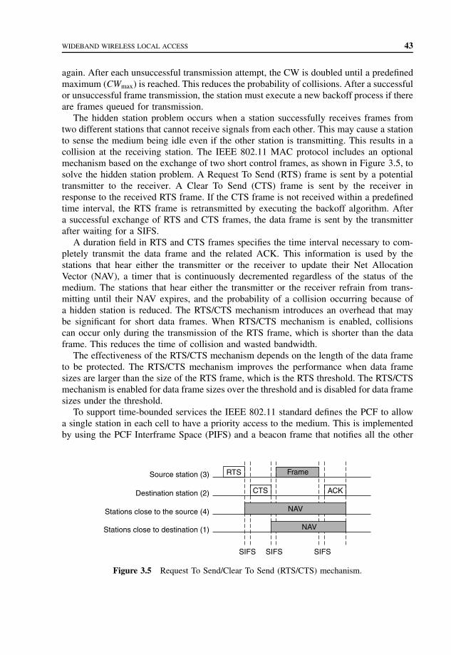
WIDEBAND WIRELESS LOCAL ACCESS 43
again. After each unsuccessful transmission attempt, the CW is doubled until a predefinedmaximum (CWmax) is reached. This reduces the probability of collisions. After a successfulor unsuccessful frame transmission, the station must execute a new backoff process if thereare frames queued for transmission.
The hidden station problem occurs when a station successfully receives frames fromtwo different stations that cannot receive signals from each other. This may cause a stationto sense the medium being idle even if the other station is transmitting. This results in acollision at the receiving station. The IEEE 802.11 MAC protocol includes an optionalmechanism based on the exchange of two short control frames, as shown in Figure 3.5, tosolve the hidden station problem. A Request To Send (RTS) frame is sent by a potentialtransmitter to the receiver. A Clear To Send (CTS) frame is sent by the receiver inresponse to the received RTS frame. If the CTS frame is not received within a predefinedtime interval, the RTS frame is retransmitted by executing the backoff algorithm. Aftera successful exchange of RTS and CTS frames, the data frame is sent by the transmitterafter waiting for a SIFS.
A duration field in RTS and CTS frames specifies the time interval necessary to com-pletely transmit the data frame and the related ACK. This information is used by thestations that hear either the transmitter or the receiver to update their Net AllocationVector (NAV), a timer that is continuously decremented regardless of the status of themedium. The stations that hear either the transmitter or the receiver refrain from trans-mitting until their NAV expires, and the probability of a collision occurring because ofa hidden station is reduced. The RTS/CTS mechanism introduces an overhead that maybe significant for short data frames. When RTS/CTS mechanism is enabled, collisionscan occur only during the transmission of the RTS frame, which is shorter than the dataframe. This reduces the time of collision and wasted bandwidth.
The effectiveness of the RTS/CTS mechanism depends on the length of the data frameto be protected. The RTS/CTS mechanism improves the performance when data framesizes are larger than the size of the RTS frame, which is the RTS threshold. The RTS/CTSmechanism is enabled for data frame sizes over the threshold and is disabled for data framesizes under the threshold.
To support time-bounded services the IEEE 802.11 standard defines the PCF to allowa single station in each cell to have a priority access to the medium. This is implementedby using the PCF Interframe Space (PIFS) and a beacon frame that notifies all the other
RTSSource station (3)
Destination station (2)
Stations close to the source (4)
Stations close to destination (1)
CTS
NAV
NAV
SIFS SIFS SIFS
ACK
Frame
Figure 3.5 Request To Send/Clear To Send (RTS/CTS) mechanism.

44 WIRELESS LOCAL AREA NETWORKS
stations in the cell not to initiate transmissions for the length of the Contention-FreePeriod (CFP). When all the stations are silenced, the PCF station allows a given station tohave contention-free access by using an optional polling frame sent by the PCF station.The length of the CFP can vary within each CFP repetition interval, depending on thesystem load.
3.2.5 ETSI HIPERLAN
HIPERLAN standards defined by ETSI are high performance radio LANs. There are fourHIPERLAN types illustrated in Figure 3.6 with the operating frequencies and indicativedata transfer rates on the radio interface.
In HIPERLAN Type 1, which is also Wireless 8802 LAN, the HIPERLAN Chan-nel Access Mechanism (CAM) is based on channel sensing and a contention resolutionscheme called Elimination Yield – Non-preemptive Priority Multiple Access (EY-NPMA).The channel status is sensed by each station in the network. If the channel is sensed asbeing idle for at least 1700 bit periods, the channel is considered free, and the station isallowed to start transmission of the data frame. Each data frame transmission must beacknowledged by an ACK from the destination station.
If the channel is not free when a frame transmission is desired, a channel access withsynchronization takes place. Synchronization is performed at the end of the previoustransmission interval, and the channel access cycle begins according to the EY-NPMAscheme. The channel access cycle consists of three phases: prioritization, contention, andtransmission. Figure 3.7 shows an example of a channel access cycle with synchronization.
Prioritization phase is used to allow only contending stations with the highest priorityframes to participate in the next phase. A CAM priority level h is assigned to each frame.Priority levels are numbered from 0 to (H − 1), where 0 is the highest priority level. Theprioritization phase consists of at most H prioritization slots, each 256 bit periods long.During priority detection, each station that has a frame with CAM priority level h sensesthe channel for the first h prioritization slots. In priority assertion, if the channel is idleduring this interval, the station transmits a burst in the (h + 1)th slot, and it is admittedto the contention phase. Otherwise, it stops contending and waits for the channel accesscycle. The contention phase starts immediately after transmission prioritization burst andconsists of two further phases – elimination and yield.
HIPERLANType 4
Wireless ATMinterconnect
DLC
PHY(17 GHz)
(155 Mb s−1)
HIPERLANType 3
Wireless ATMremote access
DLC
PHY(5 GHz)
(20 Mb s−1)
HIPERLANType 2
Wireless ATMshort-range
access
DLC
PHY(5 GHz)
(20 Mb s−1)
HIPERLANType 1
Wireless 8802LAN
MAC
PHY(5 GHz)
(23 Mb s−1)
Figure 3.6 HIPERLAN types.

WIDEBAND WIRELESS LOCAL ACCESS 45
Prio
ritiz
atio
nph
ase
Prio
rity
dete
ctio
nP
riorit
yas
sert
ion
Cyc
lesy
ncro
niza
tion
inte
rval
Con
tent
ion
phas
eTr
ansm
issi
onph
ase
Dat
a fr
ame
Yie
ldph
ase
DB
Sur
viva
lve
rific
atio
nin
terv
al
Elim
inat
ion
phas
e
AC
K
Fig
ure
3.7
Cha
nnel
acce
sscy
cle
with
sync
hron
izat
ion.
46 WIRELESS LOCAL AREA NETWORKS
The elimination phase consists of at most n elimination slots, each 256 bit periodslong, followed by a 256–bit period–long elimination survival verification slot. Beginningwith the first elimination slot, each station transmits a burst for a number B of eliminationslots, according to the following truncated geometric probability distribution function:
Pr{B = b} ={(1 − q)qb 0 ≤ b < n
qn b = n
When burst transmission ends, each station senses the channel for the duration of theelimination survival verification slot. If the channel is sensed as being idle, the sta-tion is admitted to the yield phase. Otherwise, the station drops itself from contentionand waits for the next channel access cycle. The yield phase starts after the end ofthe elimination survival verification interval and consists of at most m yield slots, each64–bit periods–long. Each station listens to the channel for a number D of yield slotsbefore beginning transmission, if allowed. Variable D has a truncated geometric distribu-tion function:
Pr{D = d} ={(1 − p)pd 0 ≤ d < m
pm d = m
If the channel is sensed idle during the yield listening interval, the station is allowed tobegin the transmission phase. Otherwise, the station looses contention and waits for thenext channel access cycle.
The elimination and yield phases are complementary. The elimination phase reducesthe number N of stations taking part in the channel access cycle. The yield phase, whichperforms well with the small number of contending stations, further reduces the numberof stations allowed to transmit, possibly even to one. Furthermore, with EY-NPMA atleast one station is always allowed to transmit.
Real-time traffic transmission is supported by dynamically varying the CAM prioritydepending on the user priority and packet residual lifetime. The user priority is assignedto each packet according to the type of traffic it carries; it determines the maximum CAMpriority value the packet can reach. The residual packet lifetime is the time interval inwhich the transmission of the packet must occur before the packet must be discarded. Sincemultihop routing is supported by the standard, the residual packet lifetime is normalizedto the number of hops the packet has to traverse to reach the final destination.
HIPERLAN Type 2 is a short-range wireless access to ATM networks providing localwireless access to ATM infrastructure networks by terminals that interact with accesspoints connected to an ATM switch or multiplexer. WATM access network providesthe QoS, including the required data transfer rates the users expect from a wired ATMnetwork. The specification of HIPERLAN Type 2 is carried out by ETSI BRAN.
3.2.6 Dynamic slot assignment
Dynamic Slot Assignment (DSA++) protocol extends the ATM statistical multiplexing tothe radio interface of wireless users. The architecture of ATM multiplexer with radio cellis shown in Figure 3.8. The radio cell has a central BS and Wireless Terminals (WTs),

WIDEBAND WIRELESS LOCAL ACCESS 47
Phy
sica
lla
yer
Phy
sica
lla
yer
ATM
ATM
M-L
LCM
-MA
CM
-PH
Y
Phy
sica
lla
yerAT
M M-L
LCM
-MA
CM
-PH
Y
Phy
sica
lla
yerAT
M M-L
LCM
-MA
CM
-PH
Y
M-L
LCM
-MA
CM
-PH
Y
Use
r se
rvic
es
Use
r se
rvic
es Use
r se
rvic
es
Wire
less
AT
M te
rmin
al
Bas
e st
atio
n
Phy
sica
lla
yer
ATM
AA
L
Phy
sica
lla
yer
Phy
sica
lla
yer
Phy
sica
lla
yer
Phy
sica
lla
yer
Phy
sica
lla
yer
ATM
ATM
mul
tiple
xer
ATM
AA
L
Phy
sica
lla
yer
ATM
AA
L
Use
r se
rvic
es
Phy
sica
lla
yer
ATM
AA
L
Use
r se
rvic
es
Phy
sica
lla
yer
ATM
AA
L
Use
r se
rvic
es
ATM
term
inal
Phy
sica
lla
yer
ATM
AA
L
Fig
ure
3.8
Arc
hite
ctur
eof
AT
Mm
ultip
lexe
rw
ithra
dio
cell.

48 WIRELESS LOCAL AREA NETWORKS
and can be viewed as a distributed, virtual ATM multiplexer with a radio interface inside.This allows for a centralized master–slave type of MAC protocol, where the BS, as themaster of a radio cell, schedules the contention-free transmission of ATM cells on theuplink and downlink.
The virtual ATM multiplexer represents a distributed queuing system with queuesinside the WTs for uplink cells and the BS for downlink cells. Similarly, as in fixedATM networks with a relatively low data rate (e.g., 20 MB s−1), the QoS requirements ofreal-time oriented services can only be supported if the transmission order of ATM cellsis based on the waiting time inside the queues. The BS needs to have current knowledgeof the capacity requirements of the mobile WTs. This can be achieved by piggybackingonto uplink ATM cells the instantaneous requirements of each mobile WT. However, itmay not be possible to piggyback the newest requirements, that is, the mobile WT isidle. In this case, WTs are provided with special uplink signaling slots so that they cantransmit their capacity requests to the BS according to a random access scheme.
The DSA++ protocol is implemented on top of a Time Division Multiple Access(TDMA) channel. Time slots may carry either a signaling burst or one ATM cell alongwith the additional signaling overhead of the physical layer. A Time Division Duplex(TDD) system is implemented to build up the uplink and downlink channels.
Time slots are grouped together into signaling periods. Figure 3.9 shows a frame struc-ture of a signaling period. The length of each signaling period, and the ratio between theuplink and downlink sections, is variable and assigned dynamically by the BS to copewith the current load of the system. Each signaling period consists of four phases.
Downlink signaling : The downlink signaling burst is transmitted from the BS to the WTsand opens a signaling period of a specific length, giving information about the structureand slot assignments of the signaling period. The downlink signaling informs the WTsabout the number of slots in the other three phases and contains at least
• a reservation message for each uplink slot of the signaling period;
Signaling periodSignaling periodSignaling period
Downlink Cells Uplink Cells
Uplink Signaling
Downlink Signaling
Time
Transceiverturnaround
interval
Figure 3.9 Frame structure of a signaling period.

WIDEBAND WIRELESS LOCAL ACCESS 49
• an announcement message for each downlink slot of the signaling period;• a control message to implement the collision resolution algorithm of the random access.
Downlink cells: In this phase the downlink cells are transmitted contention-free from theBS to the WTs.
Uplink cells: Since each of these slots is assigned to specific WTs, in this phase uplinkcells are transmitted contention-free from the WTs to the BS.
Uplink signaling : During this phase, which is carried out via a sequence of short slots,the WTs have the possibility to access the channel to signal their capacity requests tothe BS.
Random access is used for transmission of the capacity requests of the WTs. To guaran-tee the QoS requirements of the connections, fast collision resolution with a deterministicdelay is essential. Since all WTs are the possible candidates to transmit via random accessand are known by the BS, an identifier splitting algorithm can be used, which leads toshort and deterministic delays to resolve any collision. The splitting algorithm groupsthe terminals into sets. All terminals in a set are allowed to transmit in a specific slot. Atransmission will only be successful if exactly one terminal in a set transmits. If a collisionoccurs, the set is divided into subsets according to the order of the splitting algorithm.In the case of an identifier splitting algorithm, the follow-up subset is determined by theidentifier of the terminal. An example of a binary identifier splitting algorithm with anidentifier space of dimension n = 4 is shown in Figure 3.10, where τp is the duration ofa period able to offer any random access slots.
In DSA++ protocol, at the beginning of each frame the identifier space of size N
is divided into a variable number t of consecutive intervals and a random access slot
nn − 1 n + 1 t [tP]
Identifierspace
5 te
rmin
als
sele
cted
rand
omly
Firs
t dig
it is
1F
irst d
igit
is 0
0000
0001
00000
1
0
1
1
0011
0111
100
001011
011
0011100011001011
10000001 10010010 10100011 10110100 11000101 11010110 11100111 1111
Figure 3.10 An example of a binary identifier splitting algorithm.

50 WIRELESS LOCAL AREA NETWORKS
is assigned to each interval. The lth interval starts with terminal il and ends with ter-minal (i{l+1} − 1), with i1 = 0, and it = (N − 1). The downlink signaling burst signalsthe interval division to the WTs by transmitting the start identifier il of each interval.The maximum time required to resolve the collision is limited because of the limited andknown number of WTs served by the BS. Petras and Kramling show that the solutiontime of a collision can be reduced by using an estimate of the transmission probability ofeach terminal to determine the size of the subsets and the splitting order.
The coding of the capacity requests and the scheduling algorithm depend on the ATM-service class. An earliest due date strategy is used for Constant Bit Rate (CBR) andreal-time Variable Bit Rate (rt-VBR) service classes. For Available Bit Rate (ABR) andUnspecified Bit Rate (UBR) service classes, Fair Weighted Queuing and First Come FirstServed (FCFS) strategies are used.
3.3 SUMMARY
In IPv6, a special address range is reserved for multicast addresses for each scope, anda multicast is only received by the hosts in this scope, which are configured to listen tothis specific multicast address. To address all hosts in a certain scope with a multicast,the multicast must be made to the predefined all-nodes address, to which all hosts mustlisten. When existing software using IPv4 is migrated to IPv6, the IPv4 broadcasts arechanged to multicasts to the all-nodes address, as this is the simplest way to maintain thecomplete functionality of the software.
In a workgroup address configuration, the host sends a DHCP Request with a Work-group Address Extension to the DHCP Server. The DHCP Server replies with a WorkgroupAddress Extension containing all workgroup addresses assigned to this host. After receiv-ing the workgroup addresses, the host sends ICMPv6 Group Membership Report to eachof its workgroup addresses to inform the multicast routers about its new membership inthese multicast groups.
OFDM modulation combined with DPA with wideband 5-MHz channels for high-speedpacket data wireless access in macrocellular and microcellular environments supports bitrates ranging from 2 to 10 Mb s−1. OFDM can largely eliminate the effects of intersymbolinterference for high-speed transmission rates in very dispersive environments. OFDMsupports interference suppression and space–time coding to enhance efficiency. DPAsupports spectrum efficiency and high-rate data access.
Several systems support broadband wireless communications and mobile user access.These are MMDS and LMDS, also called LMCS or MVDS.
Broadband wireless access is based on the TLN concept in which subscribers aregrouped into microcells, which are embedded into a macrocell. The microcells coverageuses local repeaters operating at 5.8 GHz fed by a BS through 40-GHz links. OFDMmodulation is used to allow the reception with plug-free receivers located inside thebuildings. A 40-GHz band fixed receiver provides a rooftop antenna in LOS with thetransmitting antenna. This LMDS system provides an integrated wireless return channel.
IEEE 802.11 uses data rates up to 2 Mb s−1 and defines two network topologies. Theinfrastructure-based topology allows MTs to communicate with the backbone network

PROBLEMS TO CHAPTER 3 51
through an access point. In ad hoc topology, MTs communicate with each other withoutconnectivity to the wired backbone network. HIPERLAN uses data rate 23.5 Mb s−1 andthe ad hoc topology.
DSA++ protocol extends the ATM statistical multiplexing to the radio interface ofwireless users. The architecture of ATM multiplexer with radio cell has a central BS andWTs, and can be viewed as a distributed, virtual ATM multiplexer with a radio interfaceinside. This allows for a centralized master-slave type of MAC protocol, in which the BS,as the master of a radio cell, schedules the contention-free transmission of ATM cells onthe uplink and downlink.
PROBLEMS TO CHAPTER 3
Wireless local area networks
Learning objectives
After completing this chapter, you are able to
• demonstrate an understanding of virtual LANs;• explain the role of workgroups;• explain multicasting in virtual LANs;• explain workgroup address configuration;• demonstrate an understanding of OFDM;• explain what WCDMA is;• explain DPA;• demonstrate an understanding of LMDS;• explain what MMDS is;• explain what HFR, RTTB, and RTTC are;• demonstrate an understanding of different MAC protocols for wideband wireless local
access;• explain what IEEE 802.11 and HIPERLAN standards are;• explain what Dynamic Slot Assignment (DSA++) protocol is;
Practice problems
3.1: What are the workgroups?3.2: How is multicasting done in IPv6?3.3: How is administration of workgroups designed?3.4: What peak bit rates are supported by OFDM?3.5: What is the role of WCDMA?3.6: What is the function of DPA?3.7: What is the role of BRAN?3.8: What can the MMDS systems be used for?3.9: What is the coverage for LMDS systems?
3.10: How does the user access the network?

52 WIRELESS LOCAL AREA NETWORKS
3.11: What are the services provided by the IEEE 802.11 MAC?3.12: How does the CAM work in HIPERLAN Type 1?3.13: How does the DSA++ protocol extend the ATM statistical multiplexing?
Practice problem solutions
3.1: The workgroups are groups of hosts sharing the same servers and other resourcesover the network. The hosts of a workgroup are attached to the same LAN segment,and broadcasting can be used for server detection, name resolution, and namereservation.
3.2: In IPv6, a special address range is reserved for multicast addresses for each scope,and a multicast is only received by the hosts in this scope, which are configuredto listen to this specific multicast address. To address all hosts in a certain scopewith a multicast, the multicast must be made to the predefined all-nodes address,to which all hosts must listen. When existing software using IPv4 is migrated toIPv6, the IPv4 broadcasts are changed to multicasts to the all-nodes address, as thisis the simplest way to maintain the complete functionality of the software.
IPv6 multicasting can be used to form the broadcast scope of a workgroup. Theworkgroup is the multicast group, whose hosts listen to the same multicast address,the workgroup address. A host can listen to several multicast addresses at the sametime and can be a member of several workgroups.
Multicasting exists optionally for IPv4 and is limited by a maximum of hops.The multicast in IPv6 is limited by its scope, which is the address range.
3.3: The administration of the workgroups is designed by storing the information abouthosts and their workgroups in a central database in a DHCP server. The informationis distributed by using the DHCPv6.
3.4: OFDM modulation combined with DPA with wideband 5-MHz channels for high-speed packet data wireless access in macrocellular and microcellular environments,supports peak bit rates ranging from 2 to 10 Mb s−1.
3.5: WCDMA uses 5-MHz channels and supports circuit and packet data access at384 kb s−1 nominal data rates for macrocellular wireless access. WCDMA providessimultaneous voice and data services.
3.6: DPA is based on properties of an OFDM physical layer. DPA reassigns transmissionresources on a packet-by-packet basis using high-speed receiver measurements.
3.7: BRAN provides a high-speed digital connection to the user.3.8: The MMDS systems work at frequencies lower than 5 GHz in large coverage areas
with cell radius of up to 40 km. MMDS systems can be used for transmission ofvideo and broadcast services in rural areas. Because of a large cell size, MMDSsystems do not perform well for bidirectional communication that integrates areturn channel.
3.9: The LMDS systems work with higher frequencies where larger frequency spectrumis available than that in the MMDS systems. The coverage for LMDS systemsinvolves smaller cells of up to 5-km radius, and requires repeaters to be placed ina LOS configuration. This local coverage with a large available bandwidth makesLMDS systems suitable for interactive multimedia services distribution.

PROBLEMS TO CHAPTER 3 53
3.10: The user accesses the network through HFR, RTTB, and RTTC. In HFR an RFU car-ries out signal down conversion from RF frequency to the intermediate frequency.The signal feeds the RT of each user through a bus link. In RTTB architecture thesignal feeds the user NT through point-to-point cable links. In RTTC the RFU isplaced in a common outdoor unit and is shared among several buildings.
3.11: The IEEE 802.11 MAC (Media Access Control) protocol provides asynchronousand synchronous (contention-free) services, which are provided on top of physicallayers and for different data rates. The asynchronous service is mandatory, and thesynchronous service is optional.
3.12: In HIPERLAN Type 1, which is also a Wireless 8802 LAN, the HIPERLAN CAMis based on channel sensing and a contention resolution scheme called EY-NPMA.The channel status is sensed by each station in the network. If the channel issensed as being idle for at least 1700 bit periods, the channel is considered free,and the station is allowed to start transmission of the data frame. Each data frametransmission must be acknowledged by an ACK from the destination station.
If the channel is not free when a frame transmission is desired, a channel accesswith synchronization takes place. Synchronization is performed at the end of theprevious transmission interval, and the channel access cycle begins according tothe EY-NPMA scheme. The channel access cycle consists of three phases: priori-tization, contention, and transmission.
3.13: DSA++ protocol extends the ATM statistical multiplexing to the radio interface ofwireless users. The architecture of ATM multiplexer with radio cell has a centralBS and WTs and can be viewed as a distributed, virtual ATM multiplexer witha radio interface inside. This allows for a centralized master-slave type of MACprotocol, in which the BS, as the master of a radio cell, schedules the contention-freetransmission of ATM cells on the uplink and downlink.


4
Wireless protocols
A MAC protocol for a wireless LAN provides two types of data-transfer Service AccessPoints (SAP): network and native. The network SAP offers an access to a legacy networkprotocol (e.g., IP). The native SAP provides an extended service interface that may beused by custom network protocols or user applications capable of fully exploiting theprotocol specific Quality of Service (QoS) parameters within the cell service area.
Broadband Radio Access Integrated Network (BRAIN) is used for millimeter waveband multimedia communications. In BRAIN, all Access Points (APs) need to have onlyan optical/electrical (OE) converter because BRAIN incorporates radio on fiber technolo-gies, which allow for transmitting radio signals through optical fiber cables.
The Hybrid and Adaptive MAC (HAMAC) protocol integrates fixed assignment TimeDivision Multiple Access (TDMA) protocols, reservation-based protocols, and contention-based protocols into a wireless network, simultaneously and efficiently supporting variousclasses of traffic such as Constant Bit Rate (CBR), Variable Bit Rate (VBR), and Avail-able Bit Rate (ABR) traffic. The HAMAC protocol uses a preservation slot technique tominimize the packet contention overhead in Packet Reservation Multiple Access (PRMA)protocols, while retaining most isochronous service features of TDMA protocols to servevoice and CBR traffic streams.
Adaptive Request Channel Multiple Access (ARCMA) is a Demand Assignment Multi-ple Access (DAMA) protocol with dynamic bandwidth allocation. This scheme is designedto function in a cell-based wireless network with many Mobile Stations (MSs) commu-nicating with the Base Station (BS) of their particular cell. Transmissions are done ona slot-by-slot basis without any frames. Each slot is divided into a Transmission Access(TA) slot and a Request Access (RA) minislot. The RA channel in ARCMA is capableof carrying additional information for different classes of Asynchronous Transfer Mode(ATM) service (e.g., CBR, VBR, etc.). This additional information is used by the BS toprovide better QoS support for different classes of traffic. Transmission from CBR trafficmay reserve an incremental series of slots in the duration of their transmission. No furtherrequest is needed until the CBR transmission finishes.
Mobile Telecommunications Protocols For Data Networks. Anna HacCopyright 2003 John Wiley & Sons, Ltd.
ISBN: 0-470-85056-6

56 WIRELESS PROTOCOLS
4.1 WIRELESS PROTOCOL REQUIREMENTS
The general requirements for wireless protocols supporting wireless LANs are as follows:
• The low cost is achieved by simple implementation and the use of standard multipurposemodules and components. Modularity and reconfigurability in all stages of systemdesign are the key elements to meet these requirements.
• The QoS requirements for the data-transfer service of the MAC protocol include supportfor user-defined traffic types and connection parameters. The protocol must supportreal-time data-transfer services.
• The wireless LAN can be used both as an extension and as an alternative to a wiredLAN. Therefore, for interoperability requirements, the changing topology of a wire-less network, inadequate security and reliability of the medium, and protocol-specificmanagement functionality must be hidden from the network user, that is, from legacyTransmission Control Protocol/Internet Protocol (TCP/IP) applications.
• Wireless medium does not provide the same level of confidentiality and user identifica-tion as a wired system. A wireless coverage area cannot be reliably defined or restricted.Actions at the MAC layer have to be taken to provide a secure data-transfer service.
• An unlicensed and globally available frequency band must be selected for the system.• The architecture of the MAC protocol should follow a master–slave hierarchy as the
centralized control and management enables an easy and efficient support of QoSparameters and an access point for outside network resources.
• To guarantee the low cost, efficient resource management and guaranteed QoS, thenumber of simultaneous users in a single wireless LAN cell can be restricted accordingto the target environment.
• The requirement for low power consumption follows from the usage of battery poweredportable network equipment, for example, laptops. A wireless network adapter shouldnot significantly shorten the operating time of a portable terminal. Therefore, the MACprotocol should be capable of turning off the transceiver during idle periods withoutmissing any relevant transmission.
4.2 MAC PROTOCOL
Hannikainen et al. present a MAC protocol for a wireless LAN that provides two typesof data-transfer SAP: network and native. The network SAP offers an access to a legacynetwork protocol (e.g., IP). The native SAP provides an extended service interface thatmay be used by custom network protocols or user applications capable of fully exploitingthe protocol specific QoS parameters within the cell service area.
The data processing block converts the user data into a more suitable form for thewireless medium. Encryption is performed for confidentiality while fragmentation andForward Error Correction (FEC) coding functions are added for better protection of thedata against transmission errors. The frame queuing and Automatic Repeat Request (ARQ)retransmissions are controlled according to assigned QoS.

MAC PROTOCOL 57
The control and management functionality consists of state machines that adapt to theinputs from the management interface and data processing modules while producing anoutput according to the current state of the system. The operational parameters are storedin the Management Information Base (MIB), which can be accessed and modified throughthe station management-user interface.
Both the Portable Station (PS) and BS functionality are assembled using the samefunctional modules. The BS functionality is achieved by adding the base-specific modules(data processing, control, and management) on top of the PS functionality. A set of BSfunctions can be included into a PS capable of executing them (for instance, a laptop).Thus, an ad hoc networking is enabled if no permanent BS service is available.
Hannikainen et al. present a connection-oriented wireless MAC protocol that uses areservation-based TDMA scheme with the shared medium. The medium access cycle isdivided into time slots that form CBR channels. Four types of channels are distinguishedby their purpose, direction, and bandwidth. These are data, contention, control, and beaconchannels. The data channel includes also acknowledgements.
The data channel can be reserved by a PS for uplink transmission of user data. Thedata is forwarded by the BS; however, a direct data transfer between two PS under a BScontrol is possible. The data channels remain reserved during data transmission and arereleased by the PS request, or by the BS in the case of an idle reserved channel.
Another uplink control channel is formed by the Acknowledgement (ACK) messagesthat follow each unicast transmission destined to a single station. The protocol uses astore and wait flow-control scheme to enable short retransmission delays and fast adapta-tion to the varying quality of radio link. The acknowledgements carry information aboutsuccessful or unsuccessful reception, and control information for bandwidth requirements,which consists of the amount and priority of data queued in a PS for transmission. Thisinformation is used by the channel-scheduling function of a BS to determine the uplinkor downlink direction of the reserved data channels and the possible requirements for anextra bandwidth for each PS.
The PS transmits uplink control messages, such as channel reservation and associationrequests, in a contention-based channel at the end of the access cycle. The contentionchannel is constructed by a series of short contention slots that are monitored for a signalcarrier or energy for Carrier Sense Multiple Access (CSMA)–based transmissions. Theamount of idle contention slots to be detected before transmitting enables various controlmessage priorities.
The BS transmits downlink control messages in the control and beacon channels.The control channel is a data channel that can be reserved for control and managementinformation transfer. Otherwise, the channel is used as a VBR data channel. The beaconchannel is used by the BS only for beacon messages. A beacon broadcasts the currentchannel reservation state for the following access cycle. Beacons also carry cell-specificinformation, such as a cell identification, structure of the access cycle, and indications fora required confidentiality with the association and data transfer. A beacon frame indicatesthe beginning of the access cycle, thus providing a TDMA cycle synchronization forPS. The beacon carries indications for buffered data to those PS that use power-savefunctionality. These stations power on their receivers only periodically to receive thepossible announcement with the beacon.

58 WIRELESS PROTOCOLS
4.3 BROADBAND RADIO ACCESSINTEGRATED NETWORK
Inoue et al. present the BRAIN for millimeter wave band multimedia communications. InBRAIN, all APs need to have only an OE converter because BRAIN incorporates radio-on-fiber technologies that allow for transmitting radio signals through optical fiber cables.
Reservation Based Slotted Idle Signal Multiple Access (RS-ISMA) is a wireless accessprotocol designed for wireless multimedia communications and implemented in the BRAINindoor-LAN prototype. In addition, a compact Radio Frequency (RF) module composed offlat antennas and a Monolithic Microwave Integrated Circuit (MMIC) was employed foreach remote station and AP. The use of large capacity Field Programmable Gate Arrays(FPGA) decreased the number of signal processing boards. System parameters such as thepacket format were optimized for Internet Protocol (IP) datagram transport to support allapplications based on IP. The function of Negative Acknowledgement (NACK) sensingwas added to RS-ISMA to ensure an efficient and smooth wireless multicast in a multipleaccess environment.
BRAIN covers service areas with multiple Basic Service Area (BSA), which includesan AP and a number of fixed and/or quasi-fixed stations (ST). ST usually employs adirectional antenna in millimeter wave band communications and communicates via AP.Traffic generated from or arriving at the BSA passes through the AP, and thus the indoorsystem is a centralized control system.
RS-ISMA is a wireless MAC protocol that is an integration of reservation-based ISMAand slotted ISMA, and it is basically a combination of random access protocol and pollingprotocol. During the reservation step, an ST transmits a short frame to make a reservationunder a random access scheme. In the information transmission step, either an isochronousor an asynchronous polling scheme is used for information transmission depending on theQoS requirements.
RS-ISMA was modified to carry IP datagram most efficiently and to support wirelessmulticast. The MAC frame format has a fixed length to increase the signal processingspeed, resulting in increased radio transmission speed. The payload of modified RS-ISMAis 64 octets and the header is 4 octets.
A Stop and Wait (SW) ARQ with a limited number of retransmissions is used forboth stream traffic and data traffic in the modified RS-ISMA because combining the TCPerror-recovery mechanism with SW ARQ allows for low-frame error rate necessary forreliable transmission of data traffic.
In multimedia wireless LAN, the retransmission scheme for downlink frame transmis-sion should enable broadcast and multicast of multimedia traffic to multiple users withouterrors. The AP, after sending a data frame, transmits a polling signal whose control sig-nal field indicates Acknowledgement Request (ACKR). In response to the ACKR framestation, ST1 does not send a frame because it has received the data frame successfully.Station ST2 sends an ACK frame that informs the AP that the data frame has not beenreceived successfully. The AP, which senses any carrier from STs during one time slotfollowing the ACKR, detects a carrier from station ST2. The AP generally does not knowwhich ST has transmitted a signal since there may be more than two STs that are sending

HYBRID AND ADAPTIVE MAC PROTOCOL 59
ACK frames because they have not received the downlink data frame without errors.After detecting any carrier, the AP retransmits the data frame, which will be received byboth stations ST1 and ST2 but will be ignored by ST1.
4.4 HYBRID AND ADAPTIVE MAC PROTOCOL
Wang and Hamdi propose a MAC protocol HAMAC, which, integrates fixed assignmentTDMA protocols, reservation-based protocols, and contention-based protocols into a wire-less network, simultaneously and efficiently supporting various classes of traffic such asCBR, VBR, and ABR traffic. The HAMAC protocol uses a preservation slot techniqueto minimize the packet contention overhead in PRMA protocols, while retaining mostisochronous service features of TDMA protocols to serve voice and CBR traffic streams.
The HAMAC protocol uses a super frame that is divided into two frames, the downlinkframe and the uplink frame. The length of the frames can vary depending on the bandwidthdemand. The downlink frame is used by the BS to broadcast the frame configurationinformation, the connection setup, the allocation information, the request information,and the data to all mobile devices. The information and the data can be broadcast usinga single burst because only the BS controls the downlink. Mobile devices can filter outirrelevant information upon receiving them. The first segment of the downlink frame isused for control signaling needed for the frame configuration to be known by all mobiledevices before starting the reception and the transmission.
In the HAMAC protocol, the uplink frame consists of three segments. The first segmentis used by the mobile devices to upload the CBR data using a TDMA round-robin scheme.There are two types of slots in this segment: the preservation slot and the normal slot.The preservation slot is used to preserve the position for a CBR connection when it is ina silent state. The length of the preservation slot should be as short as possible. Duringthe transmission of the preservation slot, all mobile devices in the same cell should haveenough time to recognize the existence of preservation slot or the existence of silent CBRconnection. The preservation slot is not useful for the BS, and it is discarded by the BSand does not appear in the downlink frame.
When the preservation slot of a CBR connection is present, the remaining bandwidth ofthe connection is free. When the CBR connection becomes active again, the preservationslot is replaced by the normal slots and the allocated bandwidth for the connection cannotbe used by the other connections and mobile devices. The HAMAC protocol avoids thereservation operation before the transmission of an active talk spurt, and the BS is notaware of the state transition of the CBR connection. As a result, there is no need tomake the presence or absence of the preservation slot known to mobile devices using adownlink frame. The preservation slot can appear or disappear without any notification.
The HAMAC protocol uses the continuous bit to compress the header informationof consecutive slots when they belong to the same traffic source. In the continuous bittechnique, the position of the slots allocated to the connections can float in the uplinkframe, rather than having the slots allocated to a connection being assigned to a fixedlocation. In HAMAC protocol, the location of the slots allocated to the connection, definedas an access point, is assigned as the function of the number of continuous bits rather

60 WIRELESS PROTOCOLS
than the absolute position relative to the beginning of the super frame. As a result, thewhole frame is used efficiently without any unusable fragments left. The location shouldbe adjusted once a CBR connection is dropped, or a new CBR connection is established.
The second segment of the frame in HAMAC protocol is used to carry bursty datapackets, which have to be reserved and allocated by the BS scheduler. Bursty data trafficoccur in large volumes; thus this segment-frame contains only the normal slots.
The third segment of the frame contains the contention slots only. The contention slotsare small minislots to reduce the overhead caused by collisions. These slots are contendedfor under the control of a permission probability with respect to different types of packets.Reservation packets and control packets are more important since they may affect theperformance of the second segment access or they may be network-management packetsthat need to be served as fast as possible. Hence, they are assigned a higher permissionprobability. The ABR data packets should not significantly affect the system performance,and they are given relatively low permission probability to contend for the minislots. Toensure that there is always a chance for reservation packets and control packets to transmit,the minimum length is set for the third segment frame.
4.5 ADAPTIVE REQUEST CHANNEL MULTIPLEACCESS PROTOCOL
ARCMA is a multiple-access protocol based on demand assignments. This scheme isbased on the Distributed Queuing Request Update Multiple Access (DQRUMA) protocoland incorporates the periodic traffic handling of PRMA. In addition, ARCMA reducescollisions in the RA channel by using an efficient adaptive request strategy.
ARCMA is a DAMA protocol with dynamic bandwidth allocation. This scheme isdesigned to function in a cell-based wireless network with many MSs communicatingwith the BS of their particular cell. Transmissions are done on a slot-by-slot basis withoutany frames. As with DQRUMA, each slot is divided into a TA slot and an RA-minislot.However, the RA channel in ARCMA is capable of carrying additional information fordifferent classes of ATM service (e.g., CBR, VBR, etc.). This additional informationis used by the BS to provide better QoS support for different classes of traffic. As inPRMA, transmission from CBR traffic may reserve an incremental series of slots in theduration of their transmission. No further request is needed until the CBR transmissionfinishes.
The BS maintains a Request Table to keep track of all successful requests and assignspermission to mobiles for transmission at different time slots. In ARCMA protocol, theBS inspects the service class of a request and gives transmission priority to delay-sensitivedata (e.g., CBR). As in the DQRUMA protocol, a piggyback (PGBK) bit is used in theuplink channel to reduce contention in the RA channel. This is especially beneficial forbursty traffic.
ARCMA implements a dynamic RA channel similar to that of DQRUMA in whichan entire uplink channel can be converted into multiple RA channels. This conversion isdone when the Request Table is empty, which in most cases indicates heavy collisionsin the request channel. ARCMA uses an algorithm that takes advantage of the random

REQUEST/ACKNOWLEDGEMENT PHASE 61
access scheme in the RA channel. We use the slotted ALOHA with Binary ExponentialBackoff (BEB) as the random access protocol for ARCMA.
ARCMA improves the spectral efficiency by reducing collisions in the RA channelwhile improving support for the various classes of ATM services.
ARCMA protocol is composed of a phase similar to DQRUMA’s request/acknow-ledgement phase and a permission/transmission phase. Both these phases are associatedwith data transmission from the MS to BS. Data transmission from the BS to MS isa straightforward operation in which the BS merely broadcasts the information (datapackets) to the entire cell. The destination MS listens to the broadcast channel and retrievesthe appropriate data packets (based on the destination Access ID). If the transmissiondestination does not reside in the same cell, the BS will forward the packet to an ATMswitch to be routed to the proper destination.
4.6 REQUEST/ACKNOWLEDGEMENT PHASE
The request is made in the RA channel (RA minislot). The request data packet containsthe mobile’s b-bit Access ID assigned during setup. In ARCMA protocol, in additionto the Access ID, the request packet also includes the type of service being requested.The protocol provides additional support for periodic traffic (i.e., CBR). Since traffic canbe either CBR or non-CBR, only a single bit is required to identify the service type asshown in Figure 4.1. This bit is transmitted together with the request packet in the RA
ACK Channel Perm Channel
DD channel
TA channel
RA channel
Time slot kTime slot k − 1 Time slot k + 1
Downlink
Service-type bit(CBR bit)
PGBK bit
Uplink
Figure 4.1 Timing diagram for the ARMCA protocol.
62 WIRELESS PROTOCOLS
channel. DQRUMA provides no distinction between requests of different service types.The distinction provided in ARCMA is used by the BS to assign priority to CBR traffic.
Like most DAMA, the request channel uses a random access protocol for transmission.ARCMA uses the Slotted ALOHA with BEB algorithm. The BEB scheme is a stabilizationstrategy for protocols with limited feedback such as Slotted ALOHA. When a packetinitially arrives at the buffer, a request is transmitted immediately in the next time slot.If there is a collision, the probability of retransmission, qr is set to a half. If a secondcollision occurs, qr is set to a quarter. After i unsuccessful transmissions, the probabilityof retransmission is given by qr = 2−i . That is, after i collisions, the probability ofretransmission is uniformly distributed over the next 2i time slots. However, we freezethe qr at 2−10 for any retransmission after 10 collisions to prevent the possibility ofexcessive retransmission delay due to the reduction of q.
After every random transmission, the MS needs to know if the request was successful.Since the MS does not detect collision by sensing the channel, the BS has to send aresponse to the MS indicating a successful request. When the BS receives a request fromthe RA channel, it immediately sends (broadcasts) an ACK to the MS. The BS then insertsthe new request in a Request Table to indicate that the MS has packet(s) to transmit. TheRequest Table contains all the unprocessed requests received by the BS. This table is usedfor scheduling TA. After the MS receives its acknowledgement (by listening to the ACKchannel), it listens to the downlink Perm Channel for transmission permission. MS thatdo not receive acknowledgment for their requests will retransmit their requests accordingto the slotted ALOHA scheme.
As in DQRUMA, we make use of the PGBK request bit to provide a contention-freerequest for an MS that has more than one packet in its buffer. The BS checks the PGBKbit and updates the Request Table accordingly. If the PGBK is set to 1, the BS generatesa request, for the corresponding MS, to be inserted into the Request Table. That is, apacket arriving at a nonempty buffer does not need a request for TA. There is no ACKassociated with the piggyback request. The MS merely listens to the Perm Channel forpermission to transmit the next packet in the buffer.
4.7 PERMISSION/TRANSMISSION PHASE
General traffic: The BS is responsible for allocating bandwidth (time slots) to the MS byusing a packet transmission policy. In ARCMA protocol, we use a simple, First In FirstOut (FIFO) policy. The MS that makes a request first is given permission to transmit first.The Request Table is implemented as a queue in which the request goes to the tail of thequeue and transmission permission is given to the MS at the head of the queue. The MSthat has successfully requested for transmission (RA or PGBK) listens for its Access IDin the Perm Channel. Once an MS hears its Access ID, it is allowed to transmit its datain the following time slot. The MS transmits its data in the TA channel collision-free.The BS forwards the data from the TA channel to the appropriate destination through theData Downstream (DD) downlink channel.
CBR traffic: The ARCMA protocol provides special handling for CBR traffic. Thisconnection-oriented delay-sensitive traffic is given priority in the request phase. When

PERMISSION/TRANSMISSION PHASE 63
a CBR request arrives at the BS, it is inserted in special CBR Request Queue. The CBRRequest Queue also uses the FIFO policy but requests in this queue have precedence overthose in the Request Table. All requests in the CBR Request Queue must be processedprior to those in the Request Table. Since transmission priority is always given to CBRtraffic, we must limit the number of MSs with CBR traffic in a cell. Otherwise, generaltraffic may not be given a chance to transmit. This controlling can be done during callsetup when traffic requirements are negotiated.
The transmission rate of CBR traffic is given in the form of arrival rates. This arrivalrate depends on the rate of the CBR traffic and the transmission rate of the channel. Weassume that CBR generates data packets at a constant rate, hence generating a constantarrival rate throughout the connection. CBR packets arrive at the mobile’s buffer everyN th time slot. Since the BS is aware of this, it automatically assigns a time slot, bygenerating a request in the CBR Request Queue, for that particular MS. No request isrequired by the MS for the duration of the CBR traffic. The MS only has to listen for itsPerm bits before transmitting its data. Each CBR reservation needs to be terminated at theend of its CBR transmission. This is performed using the PGBK bit. CBR transmissiondoes not involve the PGBK bit since consequent time slot allocation is based on thearrival rates. Therefore, the PGBK bit is used by CBR traffic to indicate the end of aCBR transmission. After sending the Perm bits, the BS waits for the CBR packet inthe next time slot and checks its PGBK bit. A PGBK bit with a zero value indicatesthe end of a CBR transmission and the BS will stop assigning periodic time slots forthis particular MS. By using the PGBK, no additional data-overhead is needed for thetermination procedure.
Figure 4.2 illustrates the general flow of ARCMA protocol at every MS. In ARCMA,only the first CBR data packet has to request an access. The subsequent CBR data packetsmerely have to listen to the Perm channel for transmission permission. Requests areautomatically generated by the BS.
We reduce the collisions in the RA channel by adapting to the traffic environment.We exploit idle TA slots by converting each slot into multiple RA slots. Idle time slotsoccur when there are no entries in the request queues (general and CBR). In our adaptivescheme, when the BS detects that the request queues are empty, it converts the nextuplink (otherwise idle) TA slot into R number of RA minislots as shown in Figure 4.3.The BS does this by sending a multipleRA message in the Perm Channel to all the MSs.In the next time slot (multipleRA mode), MS can randomly select one of the R channelsfor request transmission. This selection can also be statically assigned by the BS duringcall setup. To acknowledge these multiple requests, the downlink channel is similarlyconverted into R number of ACK slots.
While a similar implementation is proposed in DQRUMA, our design reduces idletime slots by considering the probability of retransmission qr . When the TA channel isfirst converted into multiple RA minislots, all new and previously unsuccessful requestsare transmitted with the probability of 1. That is, all requests are sent out immediatelyregardless of their qr . If no requests are successfully transmitted (i.e., request queuesremain empty), the uplink channel remains in the multipleRA mode. However, in this case,the MSs retransmit their requests according to their old qr (based on the BEB algorithm).Conversely, if successful requests were made during the multiple RA slots, the BS reverts

64 WIRELESS PROTOCOLS
Empty Buffer
New PacketArrival?
YES
YES
1st CBRpacket ?
YES
YES
YES
BufferEmpty?
YES
Transmit Packetwith PGBK bit via
TA Channel
NO
NO
NO
NO
NO
NO
CBRtraffic?
Request Access viaRA Channel
Listen for permissionin Perm Channel
ACK?
PERM ?
Figure 4.2 Flow chart of ARMCA protocol at each mobile.

PERFORMANCE ANALYSIS 65
Uplink
Downlink
Downlink
Uplink
RA
PGBK
Perm
DD channel
Convert tomultipleRA mode
TA channel
CBR bit
ACK
RA0
ACK0 ACK1 ACK2
RA1
CBR bit
Perm
RAM−1
ACKM−1
RA2
Figure 4.3 Time slot conversion in multipleRA mode.
the next time slot back to normal mode with a single RA minislot. Any remaining MSswith unsuccessful requests retransmit their requests using their corresponding qr .
4.8 PERFORMANCE ANALYSIS
Our main design goal is to reduce channel access delay while maintaining reasonableoverheads. Like in most DAMA protocols, the actual data transmission (in TA and DDslot) is collision-free. All collisions occur during the request phase. We focus on strategiesthat can efficiently request access without imposing severe overheads on the system. Weanalyze the performance of our ARCMA protocol by examining the additional featurethat we introduced.
By implementing the adaptive RA channel, we improved channel utilization by exploit-ing unused TA slots. While avoiding the waste of valuable transmission time, this strategyalso reduces contention in the RA channel. In the network with active MS, empty request
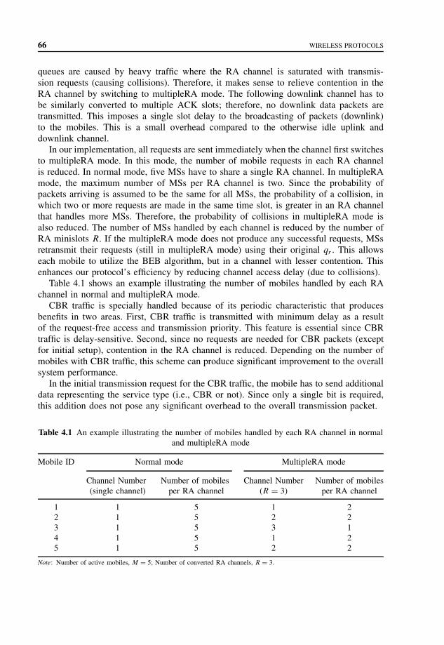
66 WIRELESS PROTOCOLS
queues are caused by heavy traffic where the RA channel is saturated with transmis-sion requests (causing collisions). Therefore, it makes sense to relieve contention in theRA channel by switching to multipleRA mode. The following downlink channel has tobe similarly converted to multiple ACK slots; therefore, no downlink data packets aretransmitted. This imposes a single slot delay to the broadcasting of packets (downlink)to the mobiles. This is a small overhead compared to the otherwise idle uplink anddownlink channel.
In our implementation, all requests are sent immediately when the channel first switchesto multipleRA mode. In this mode, the number of mobile requests in each RA channelis reduced. In normal mode, five MSs have to share a single RA channel. In multipleRAmode, the maximum number of MSs per RA channel is two. Since the probability ofpackets arriving is assumed to be the same for all MSs, the probability of a collision, inwhich two or more requests are made in the same time slot, is greater in an RA channelthat handles more MSs. Therefore, the probability of collisions in multipleRA mode isalso reduced. The number of MSs handled by each channel is reduced by the number ofRA minislots R. If the multipleRA mode does not produce any successful requests, MSsretransmit their requests (still in multipleRA mode) using their original qr . This allowseach mobile to utilize the BEB algorithm, but in a channel with lesser contention. Thisenhances our protocol’s efficiency by reducing channel access delay (due to collisions).
Table 4.1 shows an example illustrating the number of mobiles handled by each RAchannel in normal and multipleRA mode.
CBR traffic is specially handled because of its periodic characteristic that producesbenefits in two areas. First, CBR traffic is transmitted with minimum delay as a resultof the request-free access and transmission priority. This feature is essential since CBRtraffic is delay-sensitive. Second, since no requests are needed for CBR packets (exceptfor initial setup), contention in the RA channel is reduced. Depending on the number ofmobiles with CBR traffic, this scheme can produce significant improvement to the overallsystem performance.
In the initial transmission request for the CBR traffic, the mobile has to send additionaldata representing the service type (i.e., CBR or not). Since only a single bit is required,this addition does not pose any significant overhead to the overall transmission packet.
Table 4.1 An example illustrating the number of mobiles handled by each RA channel in normaland multipleRA mode
Mobile ID Normal mode MultipleRA mode
Channel Number(single channel)
Number of mobilesper RA channel
Channel Number(R = 3)
Number of mobilesper RA channel
1 1 5 1 22 1 5 2 23 1 5 3 14 1 5 1 25 1 5 2 2
Note: Number of active mobiles, M = 5; Number of converted RA channels, R = 3.

PERFORMANCE MEASURES 67
Slotted ALOHA was selected as the random access protocol in the RA channel. TheBEB algorithm was used to provide stability to the protocol. Such schemes reduce accessdelay by reducing consecutive collision in the RA channel. In addition, the multipleRAmode provides an additional layer of control for reducing collisions. In situations inwhich the random access protocol is unable to produce a successful request, the adaptivechannel access strategy coupled with the BEB algorithm significantly reduces the collisionprobability in the request channel.
We summarize the relevant features of ARCMA protocol.
• Efficient channel utilization: Schemes such as the adaptive RA channel, the specialhandling of CBR traffic, and the piggyback strategy significantly improve channelutilization.
• Slot-by-slot transmission: MS receives ACK to transmit request almost immediatelyon a slot-by-slot basis. When collision occurs, MSs are quickly aware of their failedrequest and may retransmit in the next time slot. For a protocol that transmits on aframe-by-frame (by periods) basis, the requesting MS has to wait until the next framebefore receiving any acknowledgment. A frame usually has the length (in bits) ofmultiple time slots. This causes delay that can be critical in a delay-sensitive service.In addition, there can be empty slots within that frame that could have been used forretransmission.
• Transparency to AAL: To reduce the integration complexity between wired and wire-less networks, a protocol must provide seamless inter-networking such that the ATMAdaptation-Layer (AAL) is not involved. ARCMA protocol is essentially self-containedwithin its own network layer. The strategy does not involve the AAL.
• Small RA packet : In ARCMA implementation, we use a single byte (256 mobiles)request in the RA slot. Therefore, the RA slot is just a fraction of an ATM packet(53 bytes). Collision in the RA channel only wastes a small amount of the scarcewireless spectrum.
• Preserved packet order : Since all packets are queued in the mobile’s buffer and sentsequentially on a slot-by-slot basis, the packet order is preserved. No complex reorder-ing scheme is required at the receiving end.
• Multiple uplink/downlink channels : In our discussion, we assume a single uplink anddownlink channel. In actual implementation, there can be multiple uplink and downlinkfrequencies.
4.9 PERFORMANCE MEASURES
The performance measures are the Channel Throughput (TPC) and the Average Transmis-sion Delay (DAVG). The Average Queue Length (LAVG) of the mobile’s buffer illustratesthe effects on CBR traffic. The performance parameters are defined as follows:
1. Channel Throughput (TPC): TPC is defined as the ratio of the total number of trans-mitted packets and the total number of time slots. That is, TPC = PT /TT L, where PT
is denoted as the total number of transmitted packets, and TT L is denoted as the total

68 WIRELESS PROTOCOLS
number of time slots. The TPC is measured as the number of packets transmitted pertime slot.
2. Average Transmission Delay (DAVG): DAVG is defined as the ratio of the total packettransmission delay and the number of active mobiles. Hence, DAVG = DT L/M , whereDT L is the total packet transmission delay and M is the number of active mobiles.DT L is the sum of each packet transmission delay in every active mobile. Each delayis defined as the time (number of time slots) taken, when a packet first arrives atthe mobile’s buffer to the time the packet reaches the BS. DAVG is measured by thenumber of time slots.
3. Average Queue Length (LAVG): LAVG is defined as the ratio of the total number ofpackets in all the mobiles’ buffer and the number of active mobiles. Thus, LAVG =LT L/M , where LT L is the total number of packets in all the mobiles’ buffer, and M
is the number of active mobiles. LAVG is measured by the number of packets.
Protocol design goal is to reduce DAVG while maintaining a reasonable TPC .ARCMA protocol offers better performance in terms of channel throughput and aver-
age delay under most traffic conditions. It provides better overall channel utilization byreducing contention in the RA channels. Depending on the delay tolerance of the traffic,ARCMA can achieve very high TPC . Future high-speed cellular networks (e.g., picocell)may provide a higher delay (in time slots) tolerance enabling throughput of over 90%under suitable traffic conditions.
ARCMA protocol is designed to efficiently share the limited spectral resources of awireless network. With the proliferation of multimedia portables, support for integratedmultimedia traffic is increasingly important. In addition to the limited wireless bandwidth,new protocols are required to support real-time delay-sensitive traffic. ARCMA protocolis designed to handle some of these requirements in the MAC sublayer. There are fewwireless protocols that can satisfy the high bandwidth and low Bit Error Rate (BER) ofATM networks in the wireless environment. Most of them do not provide support forthe requirements of different ATM service types. The ARCMA scheme provides bettersupport for delay-sensitive CBR traffic by prioritizing the transmission scheduling policy.In addition, ARCMA improves channel utilization by reducing collision in the requestsubchannel. ARCMA protocol provides request-free transmission for CBR and burstytraffic (within the same burst). An adaptive request channel can increase the request(without collision) probability by exploiting idle TA channels.
ARCMA performs better than DQRUMA regardless of the traffic load. Under heavytraffic, ARCMA protocol is capable of producing significantly higher channel throughputthan DQRUMA. The worst traffic scenario for ARCMA protocol is nonbursty (singlepacket burst) traffic. Every packet arrival requires transmission request, causing heavycollisions in the RA channel. Conversely, ARCMA performs extremely well with burstytraffic (e.g., VBR) capable of achieving over 85% channel throughput with limited trans-mission delay. The CBR extension enables ARCMA to satisfy the delay-sensitive CBRtraffic while reducing collisions in the RA channel. This result justifies the added com-plexity and overhead for CBR support.
Although the ARCMA protocol does not provide direct support to the other time-sensitive traffic (e.g., VBR), the strategies implemented in ARCMA protocol significantly

SUMMARY 69
reduce contention in the RA channel, allowing such traffic to transmit with less delay.ARCMA provides an efficient DAMA that is practical for implementation in a WirelessATM (WATM) network. It brings us a step closer to designing a complete protocol suitethat could be used in the wireless integration of ATM networks.
ARCMA protocol can be extended to provide direct support for other ATM servicessuch as VBR and ABR traffic. Access delay can be further reduced if there exists amechanism to specifically handle VBR or ABR mobiles. Such a mechanism alleviatesthe need for retransmitting requests packets through the RA channel. ARCMA protocoldoes not include services for network management. To provide a complete MAC sublayersupport, we need to include services such as call admission and cell handoff.
4.10 SUMMARY
RS-ISMA is a wireless access protocol designed for wireless multimedia communicationsand implemented in the BRAIN indoor-LAN prototype. In addition, a compact RF mod-ule composed of flat antennas and an MMIC was employed for each remote station andAP. The use of large capacity FPGA decreased the number of signal processing boards.System parameters such as the packet format were optimized for IP datagram trans-port to support all applications based on IP. The function of NACK sensing was addedto RS-ISMA to ensure an efficient and smooth wireless multicast in a multiple-accessenvironment.
The HAMAC protocol uses a super frame that is divided into two frames, the downlinkframe and the uplink frame. The length of the frames can vary depending on the bandwidthdemand. The downlink frame is used by the BS to broadcast the frame configurationinformation, the connection setup, the allocation information, the request information,and the data to all mobile devices. The information and the data can be broadcast usinga single burst because only the BS controls the downlink. Mobile devices can filter outirrelevant information upon receiving them. The first segment of the downlink frame isused for control signaling needed for the frame configuration to be known by all mobiledevices before starting the reception and the transmission.
ARCMA implements a dynamic RA channel in which an entire uplink channel canbe converted into multiple RA channels. This conversion is done when the RequestTable is empty, which in most cases indicates heavy collisions in the request channel.ARCMA uses an algorithm that takes advantage of the random access scheme in theRA channel. We use the slotted ALOHA with BEB as the random access protocol forARCMA.
The request is made in the RA channel (RA minislot). The request data packet containsthe mobile’s b-bit Access ID assigned during setup. In ARCMA protocol, in addition tothe Access ID, the request packet also includes the type of service being requested. Theprotocol provides additional support for periodic traffic (i.e., CBR). Since traffic can beeither CBR or non-CBR, only a single bit is required to identify the service type. This bitis transmitted together with the request packet in the RA channel. DQRUMA providesno distinction between requests of different service types. The distinction provided inARCMA is used by the BS to assign priority to CBR traffic.

70 WIRELESS PROTOCOLS
PROBLEMS TO CHAPTER 4
Wireless protocols
Learning objectives
After completing this chapter you are able to
• demonstrate an understanding of different wireless protocols.• explain a MAC protocol for wireless LAN.• explain implementation of BRAIN architecture.• explain the HAMAC protocol.• demonstrate an understanding of demand assignment multiple access protocols.• explain the role of a Request Table in ARCMA.• explain implementation of multiple RA channels.
Practice problems
4.1: What is the role of network and native service access points?4.2: What is the RS-ISMA?4.3: What are the functions of HAMAC protocol?4.4: How is transmission performed in ARCMA?4.5: What is the role of a Request Table?4.6: How is dynamic RA channel implemented?
Practice problems solutions
4.1: A MAC protocol for a wireless LAN provides two types of data transfer SAP:network and native. The network SAP offers an access to a legacy network protocols(e.g., IP). The native SAP provides an extended service interface that may be usedby custom network protocols or user applications capable of fully exploiting theprotocol specific QoS parameters within the cell service area.
4.2: RS-ISMA is a wireless access protocol designed for wireless multimedia commu-nications and implemented in the BRAIN indoor-LAN prototype. RS-ISMA is awireless MAC protocol, which is an integration of reservation-based ISMA and slot-ted ISMA, and is basically a combination of random access protocol and pollingprotocol. During the reservation step, an ST transmits a short frame to make a reser-vation under a random access scheme. In the information transmission step, either anisochronous or an asynchronous polling scheme is used for information transmissiondepending on the QoS requirements.
4.3: The HAMAC protocol integrates fixed assignment TDMA protocols, reservation-based protocols, and contention-based protocols into a wireless network, simultane-ously and efficiently supporting various classes of traffic such as CBR, VBR, andABR traffic. The HAMAC protocol uses a preservation slot technique to minimizethe packet contention overhead in PRMA protocols, while retaining most isochronousservice features of TDMA protocols to serve voice and CBR traffic streams.

PROBLEMS TO CHAPTER 4 71
4.4: ARCMA is a DAMA protocol with dynamic bandwidth allocation. This scheme isdesigned to function in a cell-based wireless network with many MSs communicatingwith the BS of their particular cell. Transmissions are done on a slot-by-slot basiswithout any frames. Each slot is divided into a TA slot and an RA minislot. TheRA channel in ARCMA is capable of carrying additional information for differentclasses of ATM service (e.g., CBR, VBR, etc.). This additional information is usedby the BS to provide better QoS support for different classes of traffic. Transmissionfrom CBR traffic may reserve an incremental series of slots in the duration of theirtransmission. No further request is needed until the CBR transmission finishes.
4.5: The BS maintains a Request Table to keep track of all successful requests and assignspermission to mobiles for transmission at different time slots. In ARCMA protocol,the BS inspects the service class of a request and gives transmission priority todelay-sensitive data (e.g., CBR). A piggyback bit is used in the uplink channel toreduce contention in the RA channel. This is especially beneficial for bursty traffic.
4.6: ARCMA implements a dynamic RA channel in which an entire uplink channel canbe converted into multiple RA channels. This conversion is done when the RequestTable is empty, which in most cases indicates heavy collisions in the request channel.ARCMA uses an algorithm that takes advantage of the random access scheme in theRA channel. We use the slotted ALOHA with BEB as the random access protocolfor ARCMA.
ARCMA improves the spectral efficiency by reducing collisions in the RA channelwhile improving support for the various classes of ATM services.


5
Protocols for wireless applications
Wireless data networks present a more constrained communication environment comparedto wired networks. Because of fundamental limitations of power, available spectrum, andmobility, wireless data networks tend to have less bandwidth than traditional networks,more latency than traditional networks, less connection stability than other network tech-nologies, and less predictable availability.
Mobile devices have a unique set of features that must be exposed in the Web, inorder to enable the creation of advanced telephony services that include location-basedservices, intelligent network functionality, including integration into the voice network,and voice/data integration.
The Wireless Application Protocol (WAP) architecture provides a scalable and extensibleenvironment for application development for mobile communication devices. The WAP pro-tocol stack has a layered design, and each layer is accessible by the layers above, and by otherservices and applications. The WAP layered architecture enables other services and applica-tions to use the features of the WAP stack through a set of well-defined interfaces. Externalapplications can access the session, transaction, security, and transport layers directly.
5.1 WIRELESS APPLICATIONS AND DEVICES
Providing Internet and World Wide Web (WWW) services on a wireless data networkpresents many challenges because most of the technology developed for the Internet hasbeen designed for desktop and larger computers that support medium to high bandwidthconnectivity over generally reliable data networks.
Mobile and wireless devices are usually handheld devices, and accessing the WWWpresents a more constrained computing environment compared to desktop computersbecause of fundamental limitations of power and form factor. Mass-market handheldwireless devices tend to have
• less powerful CPUs (Central Processor Units)• less memory [both ROM (Read Only Memory) and RAM (Random Access Memory)]
Mobile Telecommunications Protocols For Data Networks. Anna HacCopyright 2003 John Wiley & Sons, Ltd.
ISBN: 0-470-85056-6

74 PROTOCOLS FOR WIRELESS APPLICATIONS
• restricted power consumption• smaller displays• different input devices (e.g., a phone keypad, voice input, etc.).
Wireless data networks also present a more constrained communication environmentcompared to wired networks. Because of fundamental limitations of power, availablespectrum, and mobility, wireless data networks tend to have
• less bandwidth than traditional networks;• more latency than traditional networks;• less connection stability than other network technologies; and• less predictable availability.
Mobile networks are growing in complexity and the cost of providing new value-addedservices to wireless users is increasing. To meet the requirements of mobile networkoperators, solutions must be
• interoperable – terminals from different manufacturers communicate with services inthe mobile network;
• scalable – mobile network operators should be able to scale services to customer needs;• efficient – provide quality of service suited to the behavior and characteristics of
the mobile network; provide for maximum number of users for a given networkconfiguration;
• reliable – provide a consistent and predictable platform for deploying services;• secure – enable services to be extended over potentially unprotected mobile networks
while still preserving the integrity of user data; protect the devices and services fromsecurity problems such as denial of service.
The WAP Forum is an industry group dedicated to the goal of enabling sophisticatedtelephony and information services on handheld wireless devices such as mobile tele-phones, pagers, Personal Digital Assistants (PDAs), and other Wireless Terminals (WTs).Recognizing the value and utility of the WWW architecture, the WAP Forum has cho-sen to align certain components of its technology very tightly with the Internet and theWWW. The WAP specifications extend and leverage mobile networking technologies(such as digital data networking standards) and Internet technologies, such as IP, Hyper-text Transfer Protocol (HTTP), Extensible Markup Language (XML), Uniform ResourceLocators (URLs), scripting, and other content formats.
The WAP Forum drafted a global wireless protocol specification for all wireless net-works and contributes it to the industry and standards bodies. WAP enables manufacturers,network operators, content providers, and application developers to offer compatible prod-ucts and secure services on all devices and networks, resulting in greater economies ofscale and universal access to information.
The objectives of the WAP Forum are
• to bring Internet content and advanced data services to digital cellular phones andother WTs;

WIRELESS APPLICATIONS AND DEVICES 75
• to create a global wireless protocol specification that works across different wirelessnetwork technologies;
• to enable the creation of content and applications that scale across a very wide rangeof wireless bearer networks and wireless device types;
• to embrace and extend existing standards and technology wherever appropriate.
To bring Internet and WWW technologies to digital cellular phones and other WTs, thatis, adapting the Web architecture to the wireless environment, and to enable the delivery ofsophisticated information and services to mobile WTs requires working toward a unifiedinformation space, common standards, and technologies.
Wireless network bearers operate under several fundamental constraints, which placerestrictions on the type of protocols and applications offered over the network:
• Power consumption: As bandwidth increases, power consumption increases. In a mobiledevice, this reduces battery life.
• Cellular network economics: Mobile networks are typically based on a cellular archi-tecture. Cells are a resource shared by all mobile terminals in a geographic area andtypically have a fixed amount of bandwidth to be shared among all users. This charac-teristic rewards efficient use of bandwidth, as a means of reducing the overall cost ofthe network infrastructure.
• Latency : The mobile wireless environment is characterized by a very wide range ofnetwork latency, ranging from less than a second round-trip communication time tomany tens of seconds. In addition, network latency can be highly variable, dependingon the current radio transmission characteristics (e.g., in a tunnel or off network) andthe network loading in a particular area. Latency is further increased by routing, errorcorrection, and congestion avoidance characteristics of a particular network.
• Bandwidth: The mobile wireless environment is characterized by a very wide range ofnetwork characteristics and typically has far less bandwidth available than a wirelineenvironment. In addition, the economics of the wireless environment encourage theconservation of bandwidth to achieve greater density of subscribers.
Wireless devices operate under a set of physical limitations, imposed by their mobilityand form factor:
• Limited power : Any personal or handheld mobile device will have a very limited powerreserve, owing to existing battery technology. This reduces available computationalresources, transmission bandwidth, and so on.
• Size: Many mobile wireless devices are very small (handheld).
Mobile wireless devices are characterized by a different set of user interface constraintsthan that of a personal computer. To enable a consistent application-programming model,a very wide range of content scalability is required. In practice, a significant amount of theWWW content is unsuitable for use on handheld wireless devices. The problems includethe following:
• Output scalability : Existing content is designed for viewing on PC (Personal Computer)screens, whereas mobile devices have a wide range of visual display sizes, formattingand other characteristics that include voice-only output.
76 PROTOCOLS FOR WIRELESS APPLICATIONS
• Input scalability : Mobile devices feature a wide range of input models, includingnumeric keypad, very few or no programmable soft keys, and so on, and voice-only input.
Many wireless devices, for example, cellular phones and pagers, are consumer devices.These devices are used in a wide variety of environments and in a wide range of scenarios.The examples include the following:
• Simple user interfaces: Many mobile devices, in particular, cellular telephones, aremass-market consumer-oriented devices. Their user interface must be extremely simpleand easy to use.
• Single-purpose devices: The goal and purpose of most mobile devices is very focused(e.g., voice communication). This is in contrast with the general-purpose tool-orientednature of a personal computer. This motivates a very specific set-of-use cases, withvery simple and focused behavior, for example, placing a voice call.
• Hands-free, heads-up operation: Many mobile devices are used in environments inwhich the user should not be unnecessarily distracted (e.g., driving and talking).
The World Wide Web Consortium (W3C) is leading and participating in the continuingdevelopment of the Web and its standards. The new generation of Web technologies isintended to enhance the users’ and publishers’ control over the presentation of the infor-mation [e.g., through Cascading Style Sheets (CSS)], over the management of information[e.g., through Resource Description Framework (RDF)], and over its distribution [e.g.,through P3P (Platform for Privacy Preferences Project)] on the basis of technologies thatstructure and distribute data as objects, such as XML and HTTP-NG (Network Group).These technologies will be described later in the text.
A new generation of Hypertext Markup Language (HTML) is based on XML andincludes features that make it more efficient for mobile use. The other XML applica-tions such as the Wireless Markup Language (WML) and the Synchronized MultimediaIntegration Language (SMIL) have components where mobile access has an impact.
A Scalable Vector Graphics (SVG) format, which is written as a modular XML tagsetand is usable as an XML name space, can be widely implemented in browsers and author-ing tools and is suitable for widespread adoption by the content authoring community asa replacement for many uses of raster graphics. In simple cases such as in-line graphics, itshould be possible to hand the author the SVG format, and it should also be possible to cutand paste SVG graphical objects between documents and to preserve their appearance,linking behavior, and style. The graphics in Web documents are smaller, faster, moreinteractive, and displayable on a wider range of device resolutions from small mobiledevices through office computer monitors to high-resolution printers.
In the presentation model for the new generation of Web technologies, the formatting ofa document is conducted through the use of a style sheet. This is a separate document thatallows authors and users to attach style (e.g., fonts, spacing, and aural cues) to structureddocuments (e.g., HTML documents and XML applications). By separating the presentationstyle of documents from the content of documents, Cascading Style Sheets Level 2 (CSS2)and Extensible Stylesheet Language (XSL) simplifies Web and XML authoring and site
WIRELESS APPLICATIONS AND DEVICES 77
maintenance. Local processing of a document might in the future also be conducted usinga similar technology called action sheets. Style sheets can have media-specific properties,which makes them a possible candidate for use with mobile devices.
The Document Object Model is a platform- and language-neutral interface that allowsprograms and scripts to dynamically access and update the content, structure, and styleof documents. The Document Object Model provides a standard set of objects for rep-resenting HTML and XML documents, a standard model of how these objects can becombined, and a standard interface for accessing and manipulating them.
The purpose of the HTTP-NG activity is to design, implement, and test a new architec-ture for the HTTP protocol on the basis of a simple, extensible, distributed object-orientedmodel. This includes a protocol for the management of the network connections, a proto-col for transmitting messages between systems, a set of methods, interfaces, and objectsthat demonstrate a classical Web browsing case, as an example of what is possible withthe new protocol and a test bed to test the implementation.
Accessibility for people with disabilities is relevant for mobile wireless devices asthis is a potentially large marketplace (over 10% of the population), and in some casesaccessibility is required (e.g., for sales in the United States, under Section 255 of the USTelecommunications Act). In addition, functions, such as speech input or output, requiredto accommodate different kinds of disability have carry-over benefits for nondisabled usersof mobile devices, who may be using the devices in hands-free or eyes-free situations.
W3C’s Web Accessibility Initiative (WAI), in coordination with other organizations,is addressing Web accessibility through several areas of work and related technologyand guidelines to mobile wireless devices. In the area of technology, WAI works withW3C Working Groups developing technologies that can facilitate accessibility, such asHTML, CSS, SMIL, and SVG. In the area of guidelines, WAI is developing guidelinesfor accessible page authoring, user agents, and authoring tools and is coordinating withthe development of guidelines by the Mobile Access Interest Group.
The correct representation of characters is an issue in all formats of writing, not justthe Latin alphabet. The aim of this activity is for the WWW to live up to its name, and theW3C continues work on the internationalization of the Web with the aim of ensuring thatthe necessary features are included in W3C protocols and data format recommendations.The general goal of W3C’s work on internationalization is to ensure that W3C’s formatsand protocols are usable worldwide in all languages and writing systems.
Establishing trust in the new medium of the Web involves both social and techni-cal issues. Trust is established through a complex and ill-understood social mechanismincluding relationships, social norms, laws, regulations, traditions, and track records.
There is a core of technical issues that are required in any system that is to be trusted:
• The ability to make statements that have agreed-upon meanings. The W3C MetadataActivity provides a means to create machine-readable statements.
• The ability to know who made the statement and to be assured that the statement isreally theirs. The W3C Digital Signature Initiative provides a mechanism for signingmetadata in order to establish who is making the machine-readable statement.
• The ability to establish rules that permit actions to be taken, based on the statementsand a relationship to those who made the statements. The Platform for Internet Content

78 PROTOCOLS FOR WIRELESS APPLICATIONS
Selection (PICS) rules specification allows rules to be written down so that they canbe understood by machines and exchanged by users.
• The ability to negotiate binding terms and conditions. The Joint Electronic PaymentInitiative (JEPI) project created the Protocol Extension Protocol (PEP) to provide fornegotiation on the Web. Negotiation is also at the core of the Platform for PrivacyPreferences Project (P3P).
• Electronic commerce markup and payment: The W3C has two working groups in thisfield, on markup for electronic commerce and for payment initiation.
The WAP Forum’s exclusive focus is mobile wireless technologies. The goal of WAPis to create recommendations and specifications that support the creation of advancedservices on wireless devices with particular emphasis on the mobile telephone. The WAPForum is creating recommendations and technologies, which enable these services on allmobile devices and on all networks.
The WAP Forum has undertaken a variety of technical specification work relevant tothe W3C/WAP Forum collaborative efforts. All these efforts relate to the use of WorldWide Web technology on mobile devices, and in ensuring that the quality of these servicesis sufficient for mass deployment.
WAP is focused on enabling the interconnection of the Web and WTs. Significant focushas been given to mobile telephones and pagers, but all technology has been developedwith broader applicability in mind. The goal of WAP is to enable an extremely wide rangeof WTs that range from mass-market mobile telephones and pagers to more powerfuldevices to enjoy the benefits of Web technology and interconnection.
Mobile devices have a unique set of features, which must be exposed in the Web, inorder to enable the creation of advanced telephony services, and include
• location-based services;• intelligent network functionality, including integration into the voice network;• voice/data integration.
The WAP Forum is working to increase the bandwidth efficiency of Web technologyto make it more applicable to the wireless environment. WAP Forum work includesthe following:
• Smart Web proxies – proxies capable of performing intelligent transformation of pro-tocols and content, enabling more efficient use of the network, adaptation to devicecharacteristics, and adaptation to network characteristics.
• Efficient content encoding – bandwidth efficient encodings of standard Web data for-mats such as XML.
• Efficient protocols – bandwidth efficient adaptations of standard Web protocols suchas HTTP.
The WAP Forum is working to improve the behavior of Web technology due to highnetwork latencies, and in particular, is focusing on the problems of
• tuning network protocols to be adaptive and efficient given wide ranging latencies;• creating Web applications that are resilient to either high latency environments or highly
variable latency situations.

MOBILE ACCESS 79
WAP Forum work in this area includes the following:
• User agent state management• Protocol design (e.g., session state, fast session resumption, etc.).
Mobile wireless devices are characterized by a different set of user interface constraintsthan a personal computer. The WAP Forum work in this area includes the following:
• Content adaptation – mechanisms allowing a Web application to adapt gracefully tothe characteristics of the device (beyond the HTTP/1.1 content negotiation model).
• User interface scalability content formats – for example, markup and display languagesthat are suitable to impoverished devices, but which scale well to more sophisti-cated devices.
In the area of Web technologies, the focus of the WAP Forum and the W3C directlyoverlaps in the areas of intelligent proxies and protocol design, in XML applications, andin content adaptation, for example, through the use of vector graphics and style sheets.The cooperation may also occur in the area of electronic payment in which the work ofboth groups has the potential to overlap.
Instead of developing diverging solutions, it is the intent of both groups to find commonsolutions that will address mobile requirements. In the area of Web technology, the goalsoverlap, especially in the long run, allowing significant cooperation and shared develop-ment. To avoid fragmentation of the Web standards, the groups cooperate and focus onachieving the seamless integration of mobile devices into the Web.
5.2 MOBILE ACCESS
The idea of access to the Web from any place and at any time is fast becoming a reality.Web information and services are becoming accessible from a wide range of mobiledevices, from cellular phones, pagers, and in-car computers to palmtop computers andother small mobile devices. Many such devices are characterized by small screens, limitedkeyboard, low bandwidth connection, and small memory.
Mobile devices need special consideration when it comes to using Web information.Their displays are generally much smaller than a conventional computer screen and arecapable of showing only a small amount of text. On a cellular phone, for example, theremay be only enough space for three or four rows of text. Palmtop pocket-sized computershave screens smaller than a PC or a laptop, but large enough to read e-mail (electronicmail) and documents with a small amount of text. Mobile devices have limited memoryand processing speeds, and these considerations also need to be taken into account.
Mobile devices may not use all the HTML tags of a normal Web page. Given thatmobile devices are different in their capabilities from ordinary PCs, what are the repercus-sions for markup? Because of the constraints explained above, mobile devices are unlikelyto be able to use exactly the same markup as a normal page for a PC. Instead, they willuse a subset of HTML tags. The expectation is that different devices will make use ofdifferent modules of Extensible HTML (XHTML); similarly, they will support different

80 PROTOCOLS FOR WIRELESS APPLICATIONS
modules of style sheets. For example, one mobile device may use the basic XHTML textmodule and the style sheet voice module. Another device with a large screen may alsoallow the XHTML tables module.
How can a device tell the server about its capabilities? The question is, given the needsof the various devices accessing the Web, how can the server know about the capabilitiesof individual devices? How can it know that a mobile phone with a very small screen isrequesting a Web page, rather than a pocket-sized computer asking for the same informa-tion? The idea is to store data about each device, and also the preferences of its user, asa device profile. The device profiles are stored as a kind of relational database located ona Web server. W3C is working jointly with the WAP Forum writing the database modeland its fields. This work has led to the Composite Capability/Preference Profiles (CC/PP).
A CC/PP is a collection of information, which describes the capabilities, hardware,system software, and applications used to access the Web, and the particular preferencesof the users themselves. Information may include the preferred language, sound on/off,images on/off, class of device (phone, PC, printer, etc.), screen size, available bandwidth,version of HTML supported, and so on.
The location of the device profile is sent with a request for a Web page. When a devicemakes a request over the Web for a Web page, a pointer to the device profile is appendedto the request. In the case of a mobile phone, the phone requests a Uniform ResourceIdentifier (URI) in the usual way and sends a pointer in the form of a second URI toindicate where its device profile can be found.
The pointer URI goes straight to the CC/PP database. CC/PP is written in RDF, W3C’slanguage for modeling metadata, descriptive information about items on the Web. InRDF, the information encoded is always linked to Web addresses. This means that bysending a URI for the device profile, all kinds of data about that device immediatelybecomes available.
On the basis of the device profile, a Web server can choose the right content sincethe device profile is known and the Web information required is understood. XHTML isdesigned as a series of modules associated with different functionality: text, tables, forms,images, and so on. CSS and SMIL specifications have the same modular construction.If a content provider wants information to be available for different devices, differentversions of that content can be generated, for example, by using only the text modules,or by using full graphics with scripting. Thus, in its document profile, the documentspecifies the expected capabilities of the browser in terms of XHTML support, and stylesheet support. During the process of matching, the document profile is compared withthe device profile, the best fit between the two is discovered, and a suitable document isgenerated or the best fitting variant is selected.
5.3 XML PROTOCOL
Structured data such as spreadsheets, address books, configuration parameters, financialtransactions, technical drawings, and so on, are often stored on a disk, for which either abinary format or a text format can be used. The latter allows the user, if necessary, to lookat the data without the program that produced it. XML is a set of rules, guidelines, and

XML PROTOCOL 81
conventions for designing text formats for such data, in a way that produces files that areeasy to generate and read by a computer, that are unambiguous and that avoid commonpitfalls such as lack of extensibility, lack of support for internationalization/localization,and platform-dependency.
XML makes use of tags, but while HTML specifies what each tag and attribute means(and often how the text between them will look in a browser), XML uses the tags only todelimit pieces of data and leaves the interpretation of the data completely to the applicationthat reads it.
XML files are text files because that allows experts, such as programmers, to moreeasily debug applications, and in emergencies they can use a simple text editor to fixa broken XML file. But the rules for XML files are much stricter than for HTML. Aforgotten tag, or an attribute without quotes makes the file unusable, while in HTML suchpractice is often explicitly allowed, or at least tolerated. In the official XML specification,the applications are not allowed to try to second-guess the creator of a broken XML file;if the file is broken, an application has to stop right there and issue an error message.
Since XML is a text format, and it uses tags to delimit the data, XML files are nearlyalways larger than comparable binary formats. That was a conscious decision by theXML developers. Communication protocols such as modem protocols and HTTP/1.1 (thecore protocol of the Web) can compress data, thus saving bandwidth as effectively as abinary format.
Data transport is as central to modern computing as data storage and display in thenetworked, decentralized, and distributed environment of the Internet and Web. Followingthe adoption of XML for data processing, the challenge is for both sides of a sessionto agree on an application-layer transfer protocol, whether between software programs,between machines, or between organizations. Even though it accounts for most Websurfing, interactive browsing by human operating user agents can accomplish only somuch alone.
To automate negotiations and to stimulate the Web’s growth, standardized application-to-application messaging is required. The search is on for common ground that can meetthe heavy weight, commercial demands of business-to-business electronic commerce sys-tems and at the same time satisfy aesthetic requirements for a lightweight, simple networkprotocol for distributed applications.
W3C’s XML Protocol Activity addresses these needs. Its XML Protocol WorkingGroup is chartered to design the following:
• An envelope to encapsulate XML data for transfer in an interoperable manner thatallows for distributed extensibility, evolvability, as well as intermediaries such as prox-ies, caches, and gateways;
• In cooperation with the Internet Engineering Task Force (IETF), an operating system-neutral convention for the content of the envelope when used for Remote ProcedureCall (RPC) applications;
• A mechanism to serialize data based on XML Schema data types; and• In cooperation with the IETF, a nonexclusive mechanism layered on HTTP transport.
W3C provides the platform for discussion and for planning and creation of an XMLProtocol Recommendation. Through rigorous examination of the various XML protocols
82 PROTOCOLS FOR WIRELESS APPLICATIONS
in development or those already deployed, the XML Protocol Working Group is creatingan open specification for an interoperable protocol for use by all interested parties. Work-ing together with the IETF, W3C also cooperates on efforts to build on HTTP. TheXML Protocol Working Group also has contact with members of the Transport, Routing,and Packaging project. The XML Protocol Working Group also participates in the XMLCoordination Group to assure coordination with related XML efforts.
5.4 DATA ENCAPSULATION AND EVOLVABILITY
For two peers to communicate in a distributed environment, they must first agree on a unitof communication. The XML Protocol Working Group defines an encapsulation languagethat allows for applications to independently introduce extensions and new features. Thefollowing requirements for extensions and features must be met:
• They are or can be orthogonal to other extensions.• They can be deployed automatically and dynamically across the Web with no prior
coordination and no central authority.• The sender can require that the recipient either obeys the semantics defined by an
extension or aborts the processing of the message.
The Extensible Protocol (XP) specification must define the concept of an envelope oroutermost syntactical construct or structure within which all other syntactical elements ofthe message must be enclosed. The envelope must be described with XML Schema.
The XP specification must also define a processing model that defines what it meansto properly process an XP envelope or to produce a fault. This processing model must beindependent of any extensions carried within the envelope. The processing model mustapply equally to intermediaries as well as to ultimate destinations of an XP envelope.
The XP specification must define a mechanism or mechanisms that allow applicationsto submit application-specific content or information for delivery by XP. In forming thestandard for the mechanisms, the XP specification may consider support for
• carrying application-specific payloads inside the XP envelope,• referring to application-specific payloads outside the XP envelope,• carrying nested XP envelopes as application-specific data within the XP envelope,• referring to XP envelopes as application-specific data outside the XP envelope,• extending the message by extension of the XP envelope itself.
To manage the mechanisms, the XP specification must define a set of directives thatunambiguously indicate to an XP processor which extensions are optional and which aremandatory so that it can
• process all the extensions in an XP envelope or fail,• process a subset of the extensions in an XP envelope or fail.
In both the cases mentioned above, the XP processor must fail in a standard andpredictable fashion.

DATA ENCAPSULATION AND EVOLVABILITY 83
The XP specification must define the concept of protocol evolution and define a mech-anism or mechanisms for identifying XP revisions. This mechanism or mechanisms mustensure that given two XP messages it should be possible, by simple inspection of themessages, to determine if they are compatible. The specification must define the conceptsof backwards compatible and backwards incompatible evolution. Furthermore, the XPenvelope must support both optional and mandatory extensibility of applications usingthe XP envelope.
The XP specification must define a means to convey error information as a fault. Thecapability of XP carrying a fault message must not depend on any particular protocolbinding. The XP specification must define a mechanism or mechanisms to allow thetransfer of status information within an XP message without resorting to the use of XPfault messages or without depending on any particular interaction model.
Intermediaries are essential parts of building distributed systems that scale to the Web.Intermediaries can act in different capacities ranging from proxies, caches, store-and-forward hops to gateways. Experience from HTTP and other protocols has shown thatintermediaries cannot be implicitly defined but must be an explicit part of the messagepath model for any data encapsulation language. Therefore, the Working Group mustensure that the data encapsulation language supports composability both in the vertical(within a peer) as well as in the horizontal (between peers) dimension.
Intermediaries are essential parts of building distributed systems that scale on theWeb. As a result, XML Protocol must support intermediaries. Because XML Protocolseparates the message envelope from the transport binding, two types of intermediariesare possible – transport intermediaries and processing intermediaries.
With the introduction of XML and RDF schema languages, and the existing capabili-ties of object and type modeling languages such as Unified Modeling Language (UML),applications can model data at either a syntactic or a more abstract level. In order to prop-agate these data models in a distributed environment, it is required that data conformingto a syntactic schema can be transported directly, and that data conforming to an abstractschema can be converted to and from XML for transport.
The Working Group should propose a mechanism for serializing data representingnonsyntactic data models in a manner that maximizes the interoperability of independentlydeveloped Web applications. Furthermore, as data models change, the serialization of suchdata models may also change. Therefore, it is important that the data encapsulation anddata representation mechanisms are designed to be orthogonal.
Examples of relationships that will have to be serialized include subordinate rela-tionships known from attachments and manifests. Any general mechanism producedby the Working Group for serializing data models must also be able to support thisparticular case.
The XML Protocol data encapsulation and data representation mechanisms must beorthogonal. The XML Protocol data representation must support using XML Schema,simple and complex types. The XML Protocol data representation must be able to serializedata based on data models not directly representable by XML Schema, simple and complextypes. These data models include object graphs and directed labeled graphs. It must bepossible to reconstruct the original data from the data representation. Data serializedaccording to the XML Protocol data representation may contain references to data outside

84 PROTOCOLS FOR WIRELESS APPLICATIONS
the serialization. These references must be URIs. The XML Protocol data representationmust be able to encode arrays, which may be nested.
A mechanism for using HTTP transport is needed in the context of an XML Pro-tocol. This does not mean that HTTP is the only transport mechanism that can beused for the technologies developed, nor that support for HTTP transport is manda-tory. This component merely addresses the fact that HTTP transport is expected to bewidely used.
Mapping onto existing application layer protocols may lead to scalability problems,security problems, and semantic complications when the application semantics defined bythose protocols interfere with the semantics defined by an XML Protocol.
General transport issues were investigated by the HTTP-NG activity, which designeda general transport mechanism for handling out-of-order delivery of message streamsbetween two peers.
The XP specification must not mandate any dependency on specific features or mech-anisms provided by a particular transport protocol beyond the basic requirement thatthe transport protocol must have the ability to deliver the XP envelope as a unit. Thisrequirement does not preclude a mapping or binding to a transport protocol taking advan-tages of such features. It is intended to ensure that the basic XP specification will betransport neutral.
The XP specification must consider the scenario in which an XP message may berouted over possibly many different transport or application protocols as it moves betweenintermediaries on the message path. This requirement implies it must be possible to applymany transport or application protocol bindings to the XP message without informationloss from the message. The XP specification should not preclude the use of XP messagingover popular security mechanisms.
The XP specification must provide a normative description of the default binding of XPto the HTTP transport. This binding, while normative, is not to be exclusive. Any protocolbinding to HTTP must respect the semantics of HTTP and should demonstrate that it caninteroperate with existing HTTP applications. This requirement does not extend to theprovision of normative bindings to other important Internet protocols such as TransmissionControl Protocol/Internet Protocol (TCP/IP), User Datagram Protocol (UDP), and SimpleMessage Transfer Protocol (SMTP) in the XP specification.
Furthermore, the XP specification must provide a normative description of a bindingof XP to a subset of HTTP that is compatible with pre-XP Internet browser technology.
Given below is the convention for the content of the envelope when used for RPCapplications. The protocol aspects of this should be coordinated closely with the IETF.
The XML Protocol contains a convention for representing calls and replies betweenRPC applications. The conventions include the following:
• Unique specification of the program or object and procedure or method to be called onthe basis of the URI syntax.
• The ability to specify the parameters to a call in a request message and the results ofa call in the reply messages.
• Provisions for specifying errors in a reply message. Where possible, an attempt will bemade to leverage any related work done by the IETF.

WIRELESS APPLICATION PROTOCOL (WAP) 85
The RPC conventions within the XML Protocol use the Data Representation model torepresent parameters to a call in the request message and results of the call in the replymessage. There is straightforward mapping of the data types used in a wide variety ofwidely deployed programming languages and object systems.
The XML Protocol allows applications to include custom encodings for data typesused for parameters and results in RPC messages. Mechanisms for automatically bindingdata represented in RPC messages to native constructs in a programming language arenot precluded.
The XML Protocol will guarantee that RPC messages that encode parameters andresults using the default encoding for the base set of data types will be valid for anyconformant binding of the RPC conventions. Valid in this context means that the semanticsof the call should remain identical, irrespective of the programming language or objectsystem used by the caller or receiver. The subsections contained within are the same asthe subsections of the out-of-scope section of the charter.
Direct handling of binary data
XML name spaces provide a flexible and lightweight mechanism for handling languagemixing as long as those languages are expressed in XML. In contrast, there is only veryrudimentary support (base-64 encodings, etc.) for including data languages expressed inbinary formats. Such formats include commonly used image formats such as PortableNetwork Graphics (PNG), Joint Photographic Experts Group (JPEG), and so on.
Transport services are extremely important in order to actually deliver packages in anefficient and scalable manner. XML messaging proposals use existing application layerprotocols such as SMTP and HTTP. The XML Protocol Working Group focuses onproviding a (nonexclusive) mapping to HTTP.
Mapping onto existing application layer protocols may lead to scalability problems,security problems, and semantic complications when the application semantics defined bythose protocols interfere with the semantics defined by an XML Protocol.
5.5 WIRELESS APPLICATION PROTOCOL (WAP)
The WAP architecture provides a scalable and extensible environment for applicationdevelopment for mobile communication devices. The WAP protocol stack has a layereddesign, and each layer is accessible by the layers above and by other services and appli-cations. The WAP layered architecture enables other services and applications to use thefeatures of the WAP stack through a set of well-defined interfaces. External applicationscan access the session, transaction, security, and transport layers directly. The protocolstack of the WAP architecture is shown in Figure 5.1.
The Wireless Application Environment (WAE) is a general-purpose application envi-ronment based on the combination of WWW and Mobile Telephony technologies. TheWAE allows operators and service providers to build applications and services that canreach wireless platforms in an efficient and useful manner. WAE contains a microbrowserenvironment containing the following functionality:
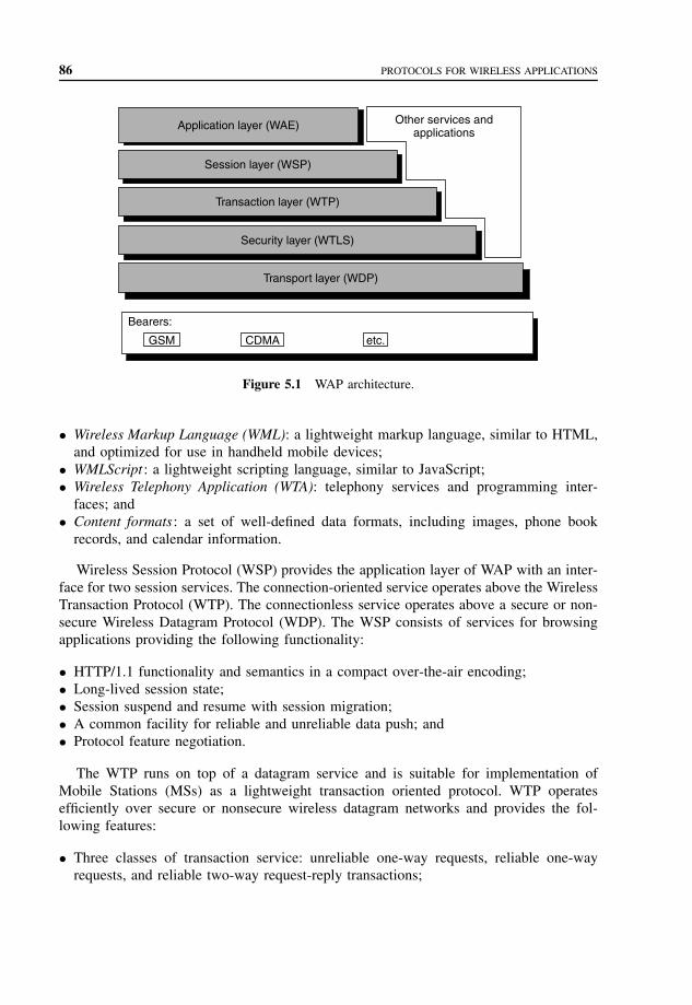
86 PROTOCOLS FOR WIRELESS APPLICATIONS
Application layer (WAE)
Session layer (WSP)
Transaction layer (WTP)
Security layer (WTLS)
Transport layer (WDP)
Bearers:
GSM CDMA etc.
Other services andapplications
Figure 5.1 WAP architecture.
• Wireless Markup Language (WML): a lightweight markup language, similar to HTML,and optimized for use in handheld mobile devices;
• WMLScript : a lightweight scripting language, similar to JavaScript;• Wireless Telephony Application (WTA): telephony services and programming inter-
faces; and• Content formats: a set of well-defined data formats, including images, phone book
records, and calendar information.
Wireless Session Protocol (WSP) provides the application layer of WAP with an inter-face for two session services. The connection-oriented service operates above the WirelessTransaction Protocol (WTP). The connectionless service operates above a secure or non-secure Wireless Datagram Protocol (WDP). The WSP consists of services for browsingapplications providing the following functionality:
• HTTP/1.1 functionality and semantics in a compact over-the-air encoding;• Long-lived session state;• Session suspend and resume with session migration;• A common facility for reliable and unreliable data push; and• Protocol feature negotiation.
The WTP runs on top of a datagram service and is suitable for implementation ofMobile Stations (MSs) as a lightweight transaction oriented protocol. WTP operatesefficiently over secure or nonsecure wireless datagram networks and provides the fol-lowing features:
• Three classes of transaction service: unreliable one-way requests, reliable one-wayrequests, and reliable two-way request-reply transactions;

WIRELESS APPLICATION PROTOCOL (WAP) 87
• Optional user-to-user reliability – WTP user triggers the confirmation of eachreceived message;
• Optional out-of-band data on acknowledgments;• Protocol Description Unit (PDU) concatenation and delayed Acknowledgement to
reduce the number of messages sent; and• Asynchronous transactions.
Wireless Transport Layer Security (WTLS) is a security protocol based upon the indus-try standard Transport Layer Security (TLS) protocol, formerly known as Secure SocketsLayer (SSL). WTLS is used with the WAP transport protocols and is optimized for useover narrow-band communication channels. WTLS provides the following features:
• Data integrity : WTLS ensures that data sent between the terminal and an applicationserver is unchanged and uncorrupted;
• Privacy : WTLS ensures that data transmitted between the terminal and an applicationserver is private and cannot be understood by any intermediate parties that may haveintercepted the data stream;
• Authentication: WTLS contains facilities to establish the authenticity of the terminaland application server;
• Denial of service protection: WTLS detects and rejects data that is replayed or notsuccessfully verified. WTLS protects the upper protocol layers.
WTLS can also be used for secure communication between terminals, for authenticationof electronic business card exchange. The applications can selectively enable or disableWTLS features depending on their security requirements and the characteristics of theunderlying network.
WDP is the transport layer protocol in the WAP architecture. The WDP layer operatesabove the data capable bearer services supported by the various network types. WDP offersa consistent service to the upper layer protocols of WAP and communicates transparentlyover one of the available bearer services.
The WDP provides a common interface to the upper layer protocols, and the security,session, and application layers can function independently of the underlying wirelessnetwork. The transport layer is adapted to specific features of the underlying bearer. Theglobal interoperability can be achieved by using mediating gateways.
The WAP protocols operate over different bearer services, including short message,circuit switched data, and packet data. The bearers offer different quality of service withrespect to throughput, error rate, and delays. The WAP protocols are designed to com-pensate for or tolerate these varying levels of service.
The WAP-layered architecture enables other services and applications to use the fea-tures of the WAP stack through a set of well-defined interfaces. External applicationscan access the session, transaction, security, and transport layers directly. This allows theWAP stack to be used for applications and services not currently specified by WAP, butvaluable for the wireless market.
Figure 5.2 shows possible protocol stacks using WAP technology. The first stack repre-sents a WAP application, a WAE user agent, running over WAP technology. The next stack

88 PROTOCOLS FOR WIRELESS APPLICATIONS
WAE
WSP
WTP
WDP WDP
WTP
No layer No layer No layerWTLS WTLS WTLS
UDP UDP UDP
IP Non-IP IP Non-IP IP Non-IP
WDP
WAP technology
Outside of WAP
Applicationsover datagram
transport
Applicationsover transactions
WAEuser agents
Figure 5.2 WAP stacks.
shows applications and services that require transaction services with or without security.The last stack shows applications and services that only require datagram transport withor without security.
5.6 SUMMARY
Mobile networks are growing in complexity and the cost of providing new value-addedservices to wireless users is increasing. To meet the requirements of mobile networkoperators, solutions must be: interoperable, scalable, efficient, reliable, and secure.
The WAP Forum is an industry group dedicated to the goal of enabling sophisticatedtelephony and information services on handheld wireless devices such as mobile tele-phones, pagers, PDAs and other WTs. Recognizing the value and utility of the WorldWide Web architecture, the WAP Forum has chosen to align certain components ofits technology very tightly with the Internet and the WWW. The WAP specificationsextend and leverage mobile networking technologies (such as digital data networkingstandards) and Internet technologies, such as IP, HTTP, XML, URLs, scripting, and othercontent formats.
Structured data such as spreadsheets, address books, configuration parameters, financialtransactions, technical drawings, and so on are often stored on a disk, for which they canuse either a binary format or a text format. The latter allows the user, if necessary, to lookat the data without the program that produced it. XML is a set of rules, guidelines, andconventions for designing text formats for such data, in a way that produces files that areeasy to generate and read by a computer, that are unambiguous and that avoid commonpitfalls such as lack of extensibility, lack of support for internationalization/localization,and platform-dependency.

PROBLEMS TO CHAPTER 5 89
The XP specification must define the concept of an envelope or outermost syntacticalconstruct or structure within which all other syntactical elements of the message must beenclosed. The envelope must be described with XML Schema.
The WAP protocols operate over different bearer services, including short message,circuit switched data, and packet data. The bearers offer different quality of service withrespect to throughput, error rate, and delays. The WAP protocols are designed to com-pensate for or tolerate these varying levels of service.
The WAP-layered architecture enables other services and applications to use the fea-tures of the WAP stack through a set of well-defined interfaces. External applicationscan access the session, transaction, security, and transport layers directly. This allows theWAP stack to be used for applications and services not currently specified by WAP, butvaluable for the wireless market.
PROBLEMS TO CHAPTER 5
Protocols for wireless applications
Learning objectives
After completing this chapter, you are able to
• demonstrate an understanding of mobile and wireless devices;• explain the features of mobile and wireless devices;• explain how to access the Web;• explain the protocols, and applications;• demonstrate an understanding of WAP.• explain the role of WAE;• explain WSP, WTP, and WDP;• explain WTLS.
Practice problems
5.1: What are the features of mobile and wireless devices?5.2: What are the special considerations for mobile devices when it comes to using Web
information?5.3: Why are XML files text files?5.4: What is WAP architecture?5.5: What is the functionality of the WAE microbrowser environment?5.6: What is the role of WSP?5.7: What is the role of WTP?5.8: What is the role of WTLS?5.9: What is the role of WDP?
Practice problem solutions
5.1: Mobile and wireless devices are usually handheld devices, and accessing the WorldWide Web presents a more constrained computing environment compared to desktop

90 PROTOCOLS FOR WIRELESS APPLICATIONS
computers because of fundamental limitations of power and form factor. Mass-markethandheld wireless devices tend to have: less powerful CPUs, less memory (bothROM and RAM), restricted power consumption, smaller displays, and different inputdevices (e.g., a phone keypad, voice input, etc.).
5.2: Mobile devices need special consideration when it comes to using Web information.Their displays are generally much smaller than a conventional computer screen andare capable of showing only a small amount of text. On a cellular phone, for example,there may be only enough space for three or four rows of text. Palmtop pocket-sizedcomputers have screens smaller than a PC or laptop, but large enough to read e-mail(electronic mail) and documents with a small amount of text. Mobile devices havelimited memory and processing speeds, and these considerations also need to betaken into account.
5.3: XML files are text files because that allows experts, such as programmers, to moreeasily debug applications, and in emergencies they can use a simple text editor to fixa broken XML file. But the rules for XML files are much stricter than for HTML. Aforgotten tag, or an attribute without quotes makes the file unusable, while in HTMLsuch practice is often explicitly allowed, or at least tolerated. In the official XMLspecification, the applications are not allowed to try to second-guess the creator ofa broken XML file; if the file is broken, an application has to stop right there andissue an error message.
5.4: The WAP architecture provides a scalable and extensible environment for applica-tion development for mobile communication devices. The WAP protocol stack hasa layered design, and each layer is accessible by the layers above, and by otherservices and applications. The WAP-layered architecture enables other services andapplications to use the features of the WAP stack through a set of well-defined inter-faces. External applications can access the session, transaction, security, and transportlayers directly.
5.5: The WAE is a general-purpose application environment based on the combination ofWWW and Mobile Telephony technologies. The WAE allows operators and serviceproviders to build applications and services that can reach wireless platforms in anefficient and useful manner. WAE contains a microbrowser environment containingthe following functionality:
• Wireless Markup Language (WML): a lightweight markup language, similar toHTML, and optimized for use in handheld mobile devices;
• WMLScript : a lightweight scripting language, similar to JavaScript;• Wireless Telephony Application (WTA): telephony services and programming inter-
faces; and• Content formats: a set of well-defined data formats, including images, phone book
records, and calendar information.
5.6: WSP provides the application layer of WAP with an interface for two session services.The connection oriented service operates above the WTP. The connectionless serviceoperates above a secure or nonsecure WDP.

PROBLEMS TO CHAPTER 5 91
5.7: The WTP runs on top of a datagram service and is suitable for implementation ofMSs as a lightweight transaction oriented protocol. WTP operates efficiently oversecure or nonsecure wireless datagram networks.
5.8: WTLS is a security protocol based upon the industry standard TLS protocol, formerlyknown as SSL. WTLS is used with the WAP transport protocols and is optimizedfor use over narrow-band communication channels.WTLS can also be used for secure communication between terminals, for authenti-cation of electronic business card exchange. The applications can selectively enableor disable WTLS features depending on their security requirements and the charac-teristics of the underlying network.
5.9: WDP is the transport layer protocol in the WAP architecture. The WDP layer operatesabove the data capable bearer services supported by the various network types. WDPoffers a consistent service to the upper layer protocols of WAP and communicatestransparently over one of the available bearer services.

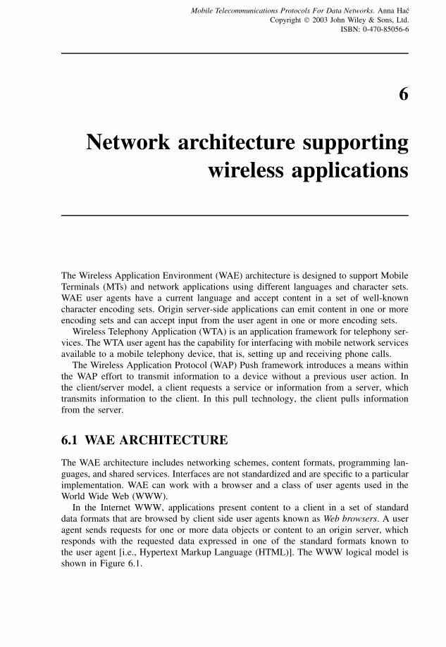
6
Network architecture supportingwireless applications
The Wireless Application Environment (WAE) architecture is designed to support MobileTerminals (MTs) and network applications using different languages and character sets.WAE user agents have a current language and accept content in a set of well-knowncharacter encoding sets. Origin server-side applications can emit content in one or moreencoding sets and can accept input from the user agent in one or more encoding sets.
Wireless Telephony Application (WTA) is an application framework for telephony ser-vices. The WTA user agent has the capability for interfacing with mobile network servicesavailable to a mobile telephony device, that is, setting up and receiving phone calls.
The Wireless Application Protocol (WAP) Push framework introduces a means withinthe WAP effort to transmit information to a device without a previous user action. Inthe client/server model, a client requests a service or information from a server, whichtransmits information to the client. In this pull technology, the client pulls informationfrom the server.
6.1 WAE ARCHITECTURE
The WAE architecture includes networking schemes, content formats, programming lan-guages, and shared services. Interfaces are not standardized and are specific to a particularimplementation. WAE can work with a browser and a class of user agents used in theWorld Wide Web (WWW).
In the Internet WWW, applications present content to a client in a set of standarddata formats that are browsed by client side user agents known as Web browsers. A useragent sends requests for one or more data objects or content to an origin server, whichresponds with the requested data expressed in one of the standard formats known tothe user agent [i.e., Hypertext Markup Language (HTML)]. The WWW logical model isshown in Figure 6.1.
Mobile Telecommunications Protocols For Data Networks. Anna HacCopyright 2003 John Wiley & Sons, Ltd.
ISBN: 0-470-85056-6

94 NETWORK ARCHITECTURE SUPPORTING WIRELESS APPLICATIONS
Client
Useragent
Response (content)
Request (URL)
Origin server
CGIscripts,
etc.
Content
Figure 6.1 WWW logical model.
Encoded request
Encoded response
Gateway
Encodersand
decoders
Origin server
CGIscripts,
etc.
Content
WAEuser
agent
Client
Request
Response (content)
Figure 6.2 WAE logical model.
All resources on the WWW are named using Internet standard Uniform Resource Loca-tors (URLs). All classes of data on the WWW are given as specific types, allowing theuser agent to correctly distinguish and present them appropriately. The WWW definesa variety of standard content formats supported by most browser user agents, includingthe HTML, the JavaScript scripting language, and other formats like bitmap image for-mats. The WWW defines a set of standard networking protocols allowing any browser tocommunicate with any origin server, for example, Hypertext Transfer Protocol (HTTP).
The WAE logical model is shown in Figure 6.2. In the WAE model, the content istransported using standard protocols in the WWW domain and an optimized HTTP-like protocol in the wireless domain. The content and services in WAE architecture arehosted on standard Web origin servers using proven technologies like Common GatewayInterface (CGI). The content is located by using WWW standard URLs. WAE supports

WAE ARCHITECTURE 95
Mobile Network Services such as Call Control and Messaging. WAE architecture supportslow bandwidth and high latency networks and considers CPU processing constraints inMTs. WAE assumes the existence of gateway functionality responsible for encoding anddecoding data transferred from and to the mobile client. The purpose of the encodingcontent delivered to the client is to minimize the size of data sent to the client OverThe Air (OTA), and to minimize the computational energy required by the client toprocess the data. The gateway functionality can be added to origin servers or placed indedicated gateways.
The main elements of the WAE model are WAE user agents, content generators,standard content encoding, and WTA. WAE user agents interpret network content ref-erenced by a URL. Content generators are the applications or services on origin servers,like CGI scripts, that produce standard content formats in response to requests from useragents in MTs. Standard content encoding allows a WAE user agent to navigate Webcontent. WTA is a collection of telephony-specific extensions for call and feature controlmechanisms providing advanced Mobile Network Services.
WAE is based on the architecture used for WWW proxy servers. The situation in whicha user agent, a browser, must connect through a proxy to reach an origin server, the serverthat contains the desired content, is very similar to the case of a wireless device accessinga server through a gateway. Most connections between the browser and the gateway useWAP Session Protocol (WSP), regardless of the protocol of the destination server. URLrefers only to the destination server’s protocol and has no bearing on what protocolsmay be used in intervening connections. The gateway performs protocol conversion bytranslating requests from WSP into other protocols, and translating the responses backinto WSP. Content conversion performed by the gateway is analogous to HTML/HTTPproxies available on the Web. In the HTTP scheme, the browser communicates with thegateway using WSP. The gateway provides protocol conversion functions to connect toan HTTP origin server.
WAE logical layers include user agents such as browsers, phone books, messageeditors, and so on, and services and formats including common elements and formatsaccessible to user agents such as Wireless Markup Language (WML), WMLScript, imageformats, vCard (electronic business card) and vCalendar (electronic calendar and schedul-ing exchange) formats, and so on. The WAE client components are shown in Figure 6.3.
WAE allows the integration of domain-specific user agents with varying architecturesand environments. A WTA user agent is specified as an extension to the WAE specifi-cation for the mobile telephony environments. The WTA extensions allow for accessingand interacting with mobile telephone features, like call control, and other applicationsassumed on the telephones, such as phone books and calendar applications. The featuresand capabilities of a user agent are decided by those who implement them.
WAE services and formats include the WML, the WMLScript (Wireless Markup Script-ing Language), WAE applications, and WAE-supported content formats.
WML is a tag-based document language. It is an application of a generalized markuplanguage and is specified as an Extensible Markup Language (XML) document type.WML is optimized for specifying presentation and user interaction on limited capabilitydevices such as telephones and wireless MTs. WML and its supporting environmentare designed using certain small narrow-band device constraints including small displays,

96 NETWORK ARCHITECTURE SUPPORTING WIRELESS APPLICATIONS
WAE
User agents
Services / formats
WTA user agent
WML user agent
Other agents
Otherapplications
andservices
WMLScript
WAP Protocol stack and services
Device OS/services
WTA srvs URLs
WMLOther srvs.& formats
Figure 6.3 WAE client components.
limited user input facilities, narrow-band network connections, limited memory resources,and limited computational resources.
The WML features include
• support for text and images;• support for user input;• navigation and history stack;• international support;• Man–Machine Interface (MMI) independence;• narrow-band optimization; and• state and context management.
WMLScript is a lightweight procedural scripting language enhancing the standardbrowsing and presentation facilities of WML with behavioral capabilities, supportingmore advanced user interface, adding intelligence to the client, providing a convenientmechanism to access the device and its peripherals, and reducing the need for round tripsto the origin server. WMLScript is an extended subset of JavaScript for narrow-banddevices and is integrated with WML for future services and in-device applications.
WAE user agents can use URL services. WAE components extend the URL semantics,for example, in WML, in which URL fragments are extended to allow linking to particularWMLScript functions. WAE allows formats for data types including images, multipartmessages, and user agent-specific formats.
WML user agent logical architecture is shown in Figure 6.4. A user submits a requestto the origin server using a WML user agent, which requests the service by using a URL
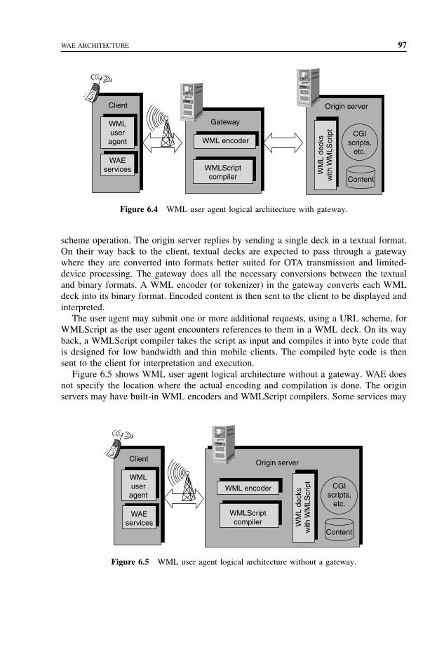
WAE ARCHITECTURE 97
Client Origin server
CGIscripts,
etc.
Content
WMLuser
agent
WAEservices
Gateway
WML encoder
WMLScriptcompiler
WM
L de
cks
with
WM
LScr
ipt
Figure 6.4 WML user agent logical architecture with gateway.
scheme operation. The origin server replies by sending a single deck in a textual format.On their way back to the client, textual decks are expected to pass through a gatewaywhere they are converted into formats better suited for OTA transmission and limited-device processing. The gateway does all the necessary conversions between the textualand binary formats. A WML encoder (or tokenizer) in the gateway converts each WMLdeck into its binary format. Encoded content is then sent to the client to be displayed andinterpreted.
The user agent may submit one or more additional requests, using a URL scheme, forWMLScript as the user agent encounters references to them in a WML deck. On its wayback, a WMLScript compiler takes the script as input and compiles it into byte code thatis designed for low bandwidth and thin mobile clients. The compiled byte code is thensent to the client for interpretation and execution.
Figure 6.5 shows WML user agent logical architecture without a gateway. WAE doesnot specify the location where the actual encoding and compilation is done. The originservers may have built-in WML encoders and WMLScript compilers. Some services may
Client Origin server
CGIscripts,
etc.
Content
WMLuser
agent
WAEservices
WML encoder
WMLScriptcompiler W
ML
deck
sw
ith W
MLS
crip
t
Figure 6.5 WML user agent logical architecture without a gateway.

98 NETWORK ARCHITECTURE SUPPORTING WIRELESS APPLICATIONS
be statically stored (or cached) in tokenized WML and WMLScript byte code formats,eliminating the need to perform fast conversion of the deck.
The WAE architecture is designed to support MTs and network applications using dif-ferent languages and character sets. WAE user agents have a current language and acceptcontent in a set of well-known character encoding sets. Origin server–side applicationscan emit content in one or more encoding sets and can accept input from the user agentin one or more encoding sets.
6.2 WTA ARCHITECTURE
WTA is an application framework for telephony services. The WTA user agent has thecapability for interfacing with mobile network services available to a mobile telephonydevice, that is, setting up and receiving phone calls. Figure 6.6 shows a configurationof the WTA architecture. In this figure, the WTA user agent, the repository (persistentstorage), and WTA Interface (WTAI) interact with each other and the other entities ina WTA-capable mobile client device. The WTA user agent is able to retrieve contentfrom the repository and WTAI. This ensures that the WTA user agent can interact withmobile network functions like setting up calls and device-specific features like using thephonebook. The WTA user agent receives network events that can be bound to content,thus enabling dynamic telephony applications.
Network events available to the WTA user agent are the result of actions taken byservices running in the WTA user agent itself. Telephony events initiated from outsidethe device are also passed to the WTA user agent and the network text message events
Man−machine interface
WTA user agent
Repository
Device-specific features Network layer
Network eventsand signaling
Mobilenetwork
WTAserver
Otherapplications
Direct user interactions
WTAI libraries
Mobileclient
WAPgateway
Figure 6.6 WTA architecture.

WTA ARCHITECTURE 99
WAEuser agent
Mobileclient
WAPgateway
Firewall(optional)
Internet Mobilenetwork
Man−machine interface
Device-specific features Network layer
Network eventsand signaling
WTAI Public Library
Direct user interaction
Otherapplications
Figure 6.7 WAE user agent and WTA Public Library.
that are explicitly directed toward another user agent. The network events caused by theWML user agent do not affect the WTA user agent.
WTAI Public Library contains functions that can be called from any WAE applicationas shown in Figure 6.7 and provides access to telephone functionality. This library allowsWML authors to include click-to-phone functionality within their content, to avoid userstyping the number by using the default MMI.
In Figure 6.7, the WAE user agent and WTAI Public Library interact with each otherand the other entities in a WTA-capable mobile client. The WAE user agent only retrievesits content via the WAP gateway and only has access to the WTAI Public Library func-tions. These functions expose simple functionality such as the ability to place a call, butdo not allow fully featured telephony control. Only a WTA user agent is able to fullycontrol the telephony features of the device. The WAE user agent is not able to receiveand react to telephony and network text events.
Figures 6.6 and 6.7 show logical separations of the two user agents. They can coexiston the same device and are likely to be implemented with common code elements.
The WTA server is a Web server delivering content requested by a client. A WTA useragent, like an Internet Web browser, uses URLs to reference content on the WTA server.A URL can be used to reference an application on a Web server, for instance, a CGI script,that is executed when it is referenced. The applications can be programmed to performa wide range of tasks, for example, generate dynamic content and interact with externalentities. By referencing applications on a WTA server, it is possible to create servicesthat use URLs to interact with the mobile network, such as an Intelligent Network node,and other entities, such as a voice mail system. The concept of referencing applications

100 NETWORK ARCHITECTURE SUPPORTING WIRELESS APPLICATIONS
2
3
2
3
1a
1a
1b
1b
Access to a URL (via the repository)
Access to a URL (via the WTA server)
Service Indication (Push)
Network event (transformed to WTA event in client)
WAPgateway
Mobilenetwork
WTAserver
Figure 6.8 Initiation of WTA services.
on a WTA server provides a simple and powerful model on how to seamlessly integrateservices in the mobile network with services executing locally in the WAP client.
WTA services appear to the client in the form of various content formats, such asWTA–WML, WMLScript, and so on. The WTA user agent executes content that ispersistently stored in the client’s repository or content retrieved from a WTA server. TheWTA user agent can act on events from the mobile network, for instance, an incoming call.
Figure 6.8 shows how to initiate a WTA service in the WTA user agent. The WTA useragent executes content within the boundary of a well-known context. The service definesthe extent of a context and its associated content. The start of a service is marked by theinitiation of a new context, and the termination of a context marks the end of a service.
The repository is a persistent storage module within the MT that may be used toeliminate the need for network access when loading and executing frequently used WTAservices. The repository also addresses the issue of how a WTA service developer ensuresthat time-critical WTA events are handled in a timely manner. The repository addressesthe issues of how the WTA services developer preprogram the device with content, andhow the WTA services developer improves the response time for a WTA service.
The repository can be accessed by a service using one of the following methods:
• A WTA event associated with a channel is detected, and the user agent invokes a URLas specified by the associated channel;
• The end user accesses services stored in the repository through an implementation-dependent representation (for instance, a menu containing the labels of the channels)of the allowed services (channels explicitly specified as user accessible by the channeldefinition) in the repository;
• The content of URL retrieved from the repository may be given to the user agent byproviding the URL in content or delivering it by Service Indication (SI).
The WTA applications, that is, content loaded or otherwise received from the WTAserver, may access the repository.

WTA ARCHITECTURE 101
WTAserver
WAPgateway
WTA services
WTA port
Mobileclient
WAE port
WAE services
Internet
Figure 6.9 WDP port numbers and access control.
A WTA service invoking WTAI functions enables access to local functions in themobile client. These functions allowing for setting up calls, and accessing the users localphone book, must ensure that only authorized WTA services are permitted to execute. Thetrusted mobile telephony service provider, which provides an acceptable level of securityin the network, can choose to run all WTA services itself not allowing other providersor it can choose to delegate the administration of its WTA services to a third party. TheWireless Datagram Protocol (WDP) uses predefined port numbers to separate a WTAservice from a common WAE service as shown in Figure 6.9. A WTA session establishedby the WTA user agent must use one of the dedicated, secure WTA ports on the gateway.The WTA user agent must not retrieve WTA content outside the WTA session. WTAcontent received outside the WTA session and Service Indication addressing the WTAuser agent but delivered outside a WTA session shall be discarded.
The repository is used to store WTA content persistently. This provides a mechanismthat ensures timely handling of content related to WTA services initiated by WTA eventsand has the following characteristics:
• The repository contains a set of channels and resources.• Resources are data downloaded with WSP (that is, WTA–WML deck) and are stored
along with their metadata, that is, content type and the HTTP 1.1 entity tag, andlocation (URL).
• A channel is a resource that contains a set of links and resources and has identityand freshness.
• Channels in the repository have a freshness lifetime (the HTTP 1.1 expiry date header),beyond which time they are considered stale. Stale channels are subject to automaticremoval by the user agent. Resources are subject to automatic removal from the repos-itory if the channel does not reference them.
• If the repository contains a channel that is not stale, it is guaranteed that the repositorycontains all resources named in that channel. The loading and unloading of a channelis an atomic operation in that no user agent will recognize the presence of the channeluntil all the content in the channel has been successfully stored in the repository.
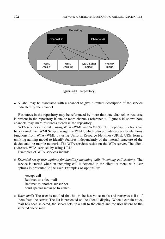
102 NETWORK ARCHITECTURE SUPPORTING WIRELESS APPLICATIONS
Repository
Channel #1 Channel #2
WMLDeck #1
WMLDeck #2
WML Scriptobject
WBMPimage
Figure 6.10 Repository.
• A label may be associated with a channel to give a textual description of the serviceindicated by the channel.
Resources in the repository may be referenced by more than one channel. A resourceis present in the repository if one or more channels reference it. Figure 6.10 shows howchannels may share resources stored in the repository.
WTA services are created using WTA–WML and WMLScript. Telephony functions canbe accessed from WMLScript through the WTAI, which also provides access to telephonyfunctions from WTA–WML by using Uniform Resource Identifier (URIs). URIs form aunifying naming model to identify features independently of the internal structure of thedevice and the mobile network. The WTA services reside on the WTA server. The clientaddresses WTA services by using URLs.
Examples of WTA services include
• Extended set of user options for handling incoming calls (incoming call section): Theservice is started when an incoming call is detected in the client. A menu with useroptions is presented to the user. Examples of options are
Accept callRedirect to voice mailRedirect to another subscriberSend special message to caller.
• Voice mail : The user is notified that he or she has voice mails and retrieves a list ofthem from the server. The list is presented on the client’s display. When a certain voicemail has been selected, the server sets up a call to the client and the user listens to theselected voice mail.

WTA ARCHITECTURE 103
• Call subscriber from message list or log : When a list of voice, fax, or e-mails or anykind of call log is displayed, the user has the option of calling the originator of aselected entry in the list or log.
The incoming call selection service is started when an incoming call is detected inthe client and a menu with various call-handling options is presented to the user asshown in Figure 6.11. A valid channel and its associated content are stored in the repos-itory. The client is not engaged in any other WTA service (i.e., no temporary eventbindings exist).
The following events in this example of incoming call selection are shown in Figure 6.11.
1. The mobile network receives an incoming call and sends a Call Indication to themobile subscriber.
2. In the client, the incoming call WTA event (wtaev-cc/ic) is generated. The repositoryis checked to find a dedicated channel. The channel provides the URL to the IncomingCall Selection service stored in the repository.
3. The user agent requests the content from the repository.4. The repository returns the requested content.5. The content is loaded into a clean context and starts executing. The service presents to
the user a list of options, from which he or she can choose how to proceed with a callin progress. In this example, the user elects to answer the call. The WTAI functionWTAIVoiceCall.accept is invoked.
AnswerHoldRejectVoice MailForward to office
>
3 Content request
RepositoryUseragent
WAPgateway
WTAserver
Mobilenetwork
Content
Connect
Bob is calling !
2
5
3
4
1
7
6
8
Mobileclient
Call Indication
Connect acknowledgement
Speech path
Figure 6.11 Incoming call selection.
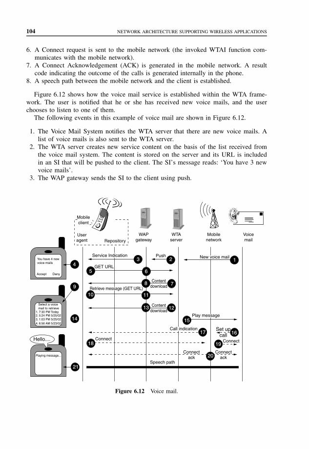
104 NETWORK ARCHITECTURE SUPPORTING WIRELESS APPLICATIONS
6. A Connect request is sent to the mobile network (the invoked WTAI function com-municates with the mobile network).
7. A Connect Acknowledgement (ACK) is generated in the mobile network. A resultcode indicating the outcome of the calls is generated internally in the phone.
8. A speech path between the mobile network and the client is established.
Figure 6.12 shows how the voice mail service is established within the WTA frame-work. The user is notified that he or she has received new voice mails, and the userchooses to listen to one of them.
The following events in this example of voice mail are shown in Figure 6.12.
1. The Voice Mail System notifies the WTA server that there are new voice mails. Alist of voice mails is also sent to the WTA server.
2. The WTA server creates new service content on the basis of the list received fromthe voice mail system. The content is stored on the server and its URL is includedin an SI that will be pushed to the client. The SI’s message reads: ‘You have 3 newvoice mails’.
3. The WAP gateway sends the SI to the client using push.
5
3 2 1
7
12
15
17 16
19
20
6
8
11
13
4
9
10
14
18
21
You have 4 newvoice mails
Accept Deny
Select a voicemail to retrieve
1. 7:30 PM Today2. 5:24 PM 5/25/023. 1:03 PM 5/25/024. 6:56 AM 5/23/02
Playing message...
Mobileclient
Useragent Repository
GET URL
Set upcall
Connect
Speech path
Connect
Connectack
Connectack
Push
Contentdownload
Contentdownload
WAPgateway
WTAserver
Mobilenetwork
Voicemail
New voice mail
Retrieve message (GET URL)
Call indication
Play message
Service Indication
Hello....
Figure 6.12 Voice mail.

WAP PUSH ARCHITECTURE 105
4. The user is notified about the SI by a message delivered with the SI. The user choosesto accept the SI.
5. A WSP Get request is sent to the WAP gateway (URL provided by the SI).6. The WAP gateway makes a WSP/HTTP conversion.7. The WTA server returns the earlier created voice mail service.8. The WAP gateway makes an HTTP/WSP conversion.9. The voice mail service is now executing in the client. The user is presented with a
list of voice mails originating from the Voice Mail System (a WTA–WML SelectList is created in Step 2). The user selects a certain voice mail to listen to.
10. Another WSP Get request is sent to the WAP gateway. The requested deck identifiesthe selected voice mail.
11. The WAP gateway makes a WSP/HTTP conversion.12. The WTA server returns the requested deck. The deck only contains one card with a
single WTA–WML task. The URL is automatically called when the card is executedand it refers to a card in the earlier downloaded voice mail content that binds theincoming call event (wtaev-cc.ic) so that the subsequent call from the Voice MailSystem will be answered automatically. Now, the WTA server is also informed aboutwhich voice mail the user has chosen to retrieve.
13. The WAP gateway makes an HTTP/WSP conversion.14. The incoming call event (wtaev-cc/ic) is temporarily bound so that the call from
the Voice Mail System will be answered automatically. To avoid that the voice mailservice answers a call from someone other than the voice mail system, the call-ing party’s phone number (callerId parameter of the wtaev-cc/ic event) should bepreferably checked.
15. The WTA server instructs the Voice Mail System to play the selected voice mail.16. The Voice Mail System instructs the mobile network to set up a call to the client.17. The mobile network sets up a call to the client.18. The client answers the call automatically as a result of the content loaded in Steps 12
to 14.19. The mobile network informs the Voice Mail System that the client has accepted
the call.20. ACKs are sent to the client and the Voice Mail System.21. A speech path is established between the Voice Mail System and the client, and the
message is played.
6.3 WAP PUSH ARCHITECTURE
The WAP Push framework introduces a means within the WAP effort to transmit infor-mation to a device without a previous user action. In the client/server model, a clientrequests a service or information from a server, which transmits information to the client.In this pull technology, the client pulls information from the server. An example of pulltechnology is WWW, in which a user enters a URL (the request), sent then to a server,which answers by sending a Web page (the response) to the user. In the push technologybased on client/server model, there is no explicit request from the client before the server

106 NETWORK ARCHITECTURE SUPPORTING WIRELESS APPLICATIONS
‘Pull’ technology
‘Push’ technology
ServerClient
Figure 6.13 Comparison of pull and push technology.
transmits its content. Figure 6.13 illustrates pull and push technology. Pull transactionsare initiated by the client, whereas push transactions are initiated by the server.
A push operation in WAP occurs when a Push Initiator transmits content to a clientusing either the Push OTA protocol or the Push Access Protocol (PAP). The Push Initiatordoes not share a protocol with the WAP client since the Push Initiator is on the Internetand the WAP client is on the WAP domain. The Push Initiator contacts the WAP Clientthrough a translating Push Proxy Gateway (PPG) from the Internet side, delivering contentfor the destination client using Internet protocols. The PPG forwards the pushed contentto the WAP domain, and the content is then transmitted over the air in the mobile networkto the destination client. The PPG may be capable of notifying the Push Initiator aboutthe final outcome of the push operation, and it may wait for the client to accept or rejectthe content in two-way mobile networks. It may also provide the Push Initiator withclient capability lookup services by letting a Push Initiator select the optimal content forthis client.
The Internet side PPG access protocol is called the PAP. The WAP side protocol iscalled OTAProtocol. The PAP uses XML messages that may be tunneled through variousInternet protocols, for example, HTTP. The OTA protocol is based on WSP services. ThePush framework with the protocols is shown in Figure 6.14.
The PPG acts as an access point for content pushes from the Internet to the mobilenetwork, and associated authentication, security, client control, and so on. The PPG ownerdecides the policies about who is able to gain access to the WAP network, who is able topush content, and so on. The PPG functionality may be built into the pull WAP gatewaythat gives the benefit of shared resources and shared sessions over the air.
Push operation
Push Proxy Gateway
WAP clientPush Initiator
(on the Internet)
PushOver-the-Air
protocol
PushAccessprotocol
Figure 6.14 Push framework with protocols.

WAP PUSH ARCHITECTURE 107
The PPG performs the following services:
• Push Initiator and authentication; access control;• parsing of and error detection in content control information;• client discovery services;• address resolution;• binary encoding and compilation of certain content types to improve efficiency OTA;• protocol conversion.
The PPG accepts pushed content from the Internet using the PAP. The PPG acknowl-edges successful parsing or reports unsuccessful parsing of the control information andmay report debug information about the content. It may also perform a callback to thepushing server when the final status of the push submission has been reached, if the PushInitiator so requests.
When the content has been accepted for delivery, the PPG attempts to find the correctdestination device and deliver the content to the client using the Push OTA protocol. ThePPG attempts to deliver the content until a timeout expires, which can be set by the PushInitiator and/or the policies of the mobile operator.
The PPG may encode WAP content types into their binary counterparts. This transactiontakes place before delivery over the air. Other content types may be forwarded as received.The Push Initiator may also precompile its content into binary form to take workload offthe PPG, for example. When the PPG receives precompiled WML, WMLScript, or SIs,they are forwarded as received.
The PPG may implement addressing aliasing schemes to enable special multi- andbroadcast cases, in which special addresses may translate to a broadcast operation.
A Push Initiator may query the PPG for client capabilities and preferences to createbetter formatted content for a particular WAP device.
The PAP is used by an Internet-based Push Initiator to push content to a mobile networkaddressing its PPG. The PAP initially uses HTTP, but it can be tunneled through any otheror future Internet protocol. The PAP carries an XML-style entity that may be used withother components in a multipart-related document.
The PAP supports the following operations:
• Push Submission (Initiator to PPG)• Result Notification (PPG to Initiator)• Push Cancellation (Initiator to PPG)• Status Query (Initiator to PPG)• Client Capabilities Query (Initiator to PPG).
The push message contains three entities: a control entity, a content entity, and option-ally a capability entity. They are used in a multipart-related message, which is sent fromthe Push Initiator to the PPG. The control entity is an XML document containing deliveryinstructions destined for the PPG, and the content entity is destined for the mobile device.
If the Push Initiator requested a confirmation of successful delivery, the message istransmitted from the PPG to the Push Initiator when the content is delivered to the mobiledevice over a two-way bearer, or transmitted to the device over a one-way bearer, and it

108 NETWORK ARCHITECTURE SUPPORTING WIRELESS APPLICATIONS
contains an XML entity. The message is also transmitted in case of a detected deliveryfailure to inform the Initiator about it.
The Push Initiator relies on the response from the PPG; a confirmed push is thenconfirmed by the WAP device only when the target application has taken responsibilityfor the pushed content. Otherwise, the application must abort the operation and the PushInitiator knows that the content never reached its destination.
An XML entity can be transmitted from the Push Initiator to the PPG requestingcancellation of the previously submitted content. The PPG responds with an XML entitywhether or not the cancellation was successful. An XML can also be transmitted fromthe Push Initiator to the PPG requesting status of the previously submitted content. ThePPG responds with an XML entity. An XML entity transmitted from the Push Initiator tothe PPG can request the capabilities of a device on the network. The PPG responds witha multipart related in two parts, in which the multipart root is the result of the request,and the second part is the capabilities of the device. The WAP is carried over HTTP/1.1in this issue of WAP Push.
The SI content type provides the ability to send notifications to end users in an asyn-chronous manner. An SI contains a short message and a URI indicating a service. Themessage is presented to the end user upon reception, and the user is given the choiceto either start the service indicated by the URI immediately or to postpone the SI forlater handling. If the SI is postponed, the client stores it and the end user is given thepossibility to act upon it at a later time.
The Push OTA protocol is a thin protocol layer on top of WSP, and it is responsiblefor transporting content from the PPG to the client and its user agents. The OTA protocolmay use WSP sessions to deliver its content. Connection-oriented pushes require that anactive WSP session is available, but a session cannot be created by the server. When thereis no active WSP session, the Push framework introduces a Session Initiation Application(SIA) in the client that listens to session requests from the OTA servers and responds bysetting up a WSP session for push purposes. The client may verify the identity informationin this request against a list of recognized OTA servers before attempting to establish anypush sessions. Push delivery may also be performed without the use of sessions in aconnectionless manner, which is needed in one-way networks.
A connection-oriented push requires an active WSP session. Only the client can createsessions. If the server receives a request for a connection-oriented push to a client, andthere are no active sessions to that client, the server cannot deliver the push content.A session request is sent to a special application in the client known as the SIA. Thisrequest contains information necessary for a client to create a push session. The SIAin the client after receiving a session request establishes a session with the PPG andindicates which applications accept content over the newly opened session. The SIA mayalso ignore the request if there is no suitable installed application as requested in thesession request.
When a client receives pushed content, a dispatcher looks at the push message headerto determine its destination application. This dispatcher is responsible for rejecting con-tent that does not have a suitable destination application installed, and for confirmingpush operations to the PPG when the appropriate application takes responsibility forpushed content.
PROBLEMS TO CHAPTER 6 109
6.4 SUMMARY
The main elements of the WAE model are WAE user agents, content generators, standardcontent encoding, and wireless telephony applications. WAE user agents interpret networkcontent referenced by a URL. Content generators are the applications or services on originservers, like CGI scripts, that produce standard content formats in response to requestsfrom user agents in MTs. Standard content encoding allows a WAE user agent to navigateWeb content. WTA is a collection of telephony-specific extensions for call and featurecontrol mechanisms providing advanced Mobile Network Services.
The repository is a persistent storage module within the MT that may be used toeliminate the need for network access when loading and executing frequently used WTAservices. The repository also addresses the issue of how a WTA service developer ensuresthat time critical WTA events are handled in a timely manner. The repository addressesthe issues of how the WTA services developer preprogram the device with content andhow the WTA services developer improves the response time for a WTA service.
A push operation in WAP occurs when a Push Initiator transmits content to a clientusing either the Push OTA protocol or the PAP. The Push Initiator does not share aprotocol with the WAP client since the Push Initiator is on the Internet and the WAPclient is on the WAP domain. The Push Initiator contacts the WAP Client through atranslating PPG from the Internet side, delivering content for the destination client usingInternet protocols. The PPG forwards the pushed content to the WAP domain, and thecontent is then transmitted over the air in the mobile network to the destination client. ThePPG may be capable of notifying the Push Initiator about the final outcome of the pushoperation, and it may wait for the client to accept or reject the content in two-way mobilenetworks. It may also provide the Push Initiator with client capability lookup services,letting a Push Initiator select the optimal content for this client.
The Internet side PPG access protocol is called the PAP. The WAP side protocol iscalled the OTAProtocol. The PAP uses XML messages that may be tunneled through var-ious Internet protocols, for example, HTTP. The OTA protocol is based on WSP services.
PROBLEMS TO CHAPTER 6
Network architecture supporting wireless applications
Learning objectives
After completing this chapter, you are able to
• demonstrate an understanding of the network architecture supporting wirelessapplications;
• explain the role of WAE architecture;• explain WTA architecture;• explain WAP Push architecture.

110 NETWORK ARCHITECTURE SUPPORTING WIRELESS APPLICATIONS
Practice problems
6.1: What are the main elements of the WAE model?6.2: What is the role of the repository in the WTA services?6.3: What is the WAP Push framework?
Practice problem solutions
6.1: The main elements of the WAE model are WAE user agents, content generators,standard content encoding, and WTA. WAE user agents interpret network contentreferenced by a URL. Content generators are the applications or services on ori-gin servers, like CGI scripts, that produce standard content formats in responseto requests from user agents in MTs. Standard content encoding allows a WAEuser agent to navigate Web content. WTA is a collection of telephony specificextensions for call and feature control mechanisms providing advanced Mobile Net-work Services.
6.2: The repository is a persistent storage module within the MT that may be used toeliminate the need for network access when loading and executing frequently usedWTA services. The repository also addresses the issue of how a WTA service devel-oper ensures that time-critical WTA events are handled in a timely manner. Therepository addresses the issues of how the WTA services developer preprogram thedevice with content, and how the WTA services developer improves the responsetime for a WTA service.
6.3: The WAP Push framework introduces a means within the WAP effort to transmitinformation to a device without a previous user action. In the client/server model, aclient requests a service or information from a server, which transmits informationto the client. In this pull technology, the client pulls information from the server. Anexample of pull technology is WWW, in which a user enters a URL (the request) sentthen to a server, which answers by sending a Web page (the response) to the user. Inthe push technology based on the client/server model, there is no explicit request fromthe client before the server transmits its content. Pull transactions are initiated bythe client, whereas push transactions are initiated by the server. A push operation inWAP occurs when a Push Initiator transmits content to a client using either the PushOTA protocol or the PAP. The Push Initiator does not share a protocol with the WAPclient since the Push Initiator is on the Internet and the WAP client is on the WAPdomain. The Push Initiator contacts the WAP Client through a translating PPG fromthe Internet side, delivering content for the destination client using Internet protocols.
7
XML, RDF, and CC/PP
Extensible Markup Language (XML) describes a class of data objects called XML doc-uments and partially describes the behavior of the computer programs that process them.XML is an application profile or restricted form of the Standard Generalized MarkupLanguage (SGML).
Resource Description Framework (RDF) can be used to create a general, yet extensibleframework for describing user preferences and device capabilities. This information can beprovided by the user to servers and content providers. The servers can use this informationdescribing the user’s preferences to customize the service or content provided. The abilityof RDF to reference profile information via URLs assists in minimizing the number ofnetwork transactions required to adapt content to a device, while the framework fits wellinto the current and future protocols.
A Composite Capability/Preference Profile (CC/PP) is a collection of the capabilitiesand preferences associated with user and the agents used by the user to access the WorldWide Web. These user agents include the hardware platform, system software, and appli-cations used by the user. User agent capabilities and references can be thought of asmetadata or properties and descriptions of the user agent hardware and software.
7.1 XML DOCUMENT
XML documents are made up of storage units called entities, which contain either parsedor unparsed data. Parsed data is made up of characters, some of which form characterdata and some of which form markup. Markup encodes a description of the document’sstorage layout and logical structure. XML provides a mechanism to impose constraintson the storage layout and logical structure.
A software module called an XML processor is used to read XML documents andprovide access to their content and structure. It is assumed that an XML processor isdoing its work on behalf of another module called the application. An XML processorreads XML data and provides the information to the application.
Mobile Telecommunications Protocols For Data Networks. Anna HacCopyright 2003 John Wiley & Sons, Ltd.
ISBN: 0-470-85056-6
112 XML, RDF, AND CC/PP
The design goals for XML are
• to be straightforwardly usable over the Internet,• to support a wide variety of applications,• to be compatible with SGML,• to create easy-to-write programs that process XML documents,• to keep the number of optional features in XML to the absolute minimum, ideally zero,• to have XML documents human-legible and reasonably clear,• to prepare XML design quickly,• to have the design of XML formal and concise,• to have XML documents that are easy to create,• to have terseness in XML markup of minimal importance.
A data object is an XML document if it is well formed, which may be valid if itmeets certain further constraints. Each XML document has both a logical and a phys-ical structure. Physically, the document is composed of units called entities. An entitymay refer to other entities to cause their inclusion in the document. A document beginsin a root or document entity. Logically, the document is composed of declarations, ele-ments, comments, character references, and Processing Instructions (PIs), all of which areindicated in the document by explicit markup. The logical and physical structures mustnest properly.
Matching the document production implies that it contains one or more elements, andthere is exactly one element, called the root or document element, no part of whichappears in the content of any other element. For all other elements, if the start-tag is inthe content of another element, the end-tag is in the content of the same element. Theelements, delimited by start- and end-tags, nest properly within each other.
A parsed entity contains text, a sequence of characters, which may represent markupor character data. Characters are classified for convenience as letters, digits, or othercharacters. A letter consists of an alphabetic or syllabic base character or an ideographiccharacter. A Name is a token beginning with a letter or one of a few punctuation characters,and continuing with letters, digits, hyphens, underscores, colons, or full stops, togetherknown as name characters. The Name spaces assign a meaning to names containing coloncharacters. Therefore, authors should not use the colon in XML names except for namespace purposes, but XML processors must accept the colon as a name character. AnNmtoken (name token) is any mixture of name characters.
Literal data is any quoted string not containing the quotation mark used as a delimiterfor that string. Literals are used for specifying the content of internal entities (EntityValue),the values of attributes (AttValue), and external identifiers (SystemLiteral). Note that aSystemLiteral can be parsed without scanning for markup.
Text consists of intermingled character data and markup. Markup takes the form ofstart-tags, end-tags, empty-element tags, entity references, character references, com-ments, Character Data (CDATA) section delimiters, document type declarations, process-ing instructions, XML declarations, text declarations, and any white space that is at thetop level of the document entity (that is, outside the document element and not inside anyother markup). All text that is not markup constitutes the character data of the document.

XML DOCUMENT 113
Comments may appear anywhere in a document outside other markup; in addition,they may appear within the document type declaration at places allowed by the grammar.They are not part of the document’s character data; an XML processor may, but need not,make it possible for an application to retrieve the text of comments. For compatibility, thestring "" (double-hyphen) must not occur within comments. Parameter entity referencesare not recognized within comments.
PIs allow documents to contain instructions for applications. PIs are not part of thedocument’s character data, but must be passed through to the application. The PI beginswith a target (PITarget) used to identify the application to which the instruction is directed.The target names XML, xml, and so on are reserved for specification standardization. TheXML Notation mechanism may be used for formal declaration of PI targets. Parameterentity references are not recognized within PIs.
Markup declarations can affect the content of the document, as passed from an XMLprocessor to an application; examples are attribute defaults and entity declarations. Thestand-alone document declaration, which may appear as a component of the XML dec-laration, signals whether there are such declarations, which appear external to the doc-ument entity or in parameter entities. An external markup declaration is defined as amarkup declaration occurring in the external subset or in a parameter entity (external orinternal, the latter being included because nonvalidating processors are not required toread them).
In a stand-alone document declaration, the value ‘yes’ indicates that there are noexternal markup declarations that affect the information passed from the XML processorto the application. The value ‘no’ indicates that there are or may be such external markupdeclarations. The stand-alone document declaration only denotes the presence of externaldeclarations; the presence, in a document, of references to external entities, when thoseentities are internally declared, does not change its stand-alone status. If there are noexternal markup declarations, the stand-alone document declaration has no meaning. Ifthere are external markup declarations but there is no stand-alone document declaration,the value no is assumed.
Each XML document contains one or more elements, the boundaries of which areeither delimited by start-tags and end-tags, or, for empty elements, by an empty-elementtag. Each element has a type, identified by name, sometimes called its Generic Identifier(GI), and may have a set of attribute specifications. Each attribute specification has aname and a value.
An element is valid if there is a declaration matching element declaration in which theName matches the element type, and one of the following holds:
1. The declaration matches EMPTY and the element has no content.2. The declaration matches CHILDREN and the sequence of child elements belongs to
the language generated by the regular expression in the content model, with optionalwhite space between the start-tag and the first child element, between child elements,or between the last child element and the end-tag.
3. The declaration matches MIXED and the content consists of character data and childelements whose types match names in the content model.
4. The declaration matches ANY, and the types of any child elements have been declared.
114 XML, RDF, AND CC/PP
The element structure of an XML document may, for validation purposes, be con-strained using element-type and attribute-list declarations. An element-type declarationconstrains the element’s content. Element-type declarations often constrain which elementtypes can appear as children of the element. At the user option, an XML processor mayissue a warning when a declaration mentions an element type for which no declaration isprovided, but this is not an error.
An element type has element content when elements of that type must contain onlychild elements (no character data), optionally separated by white space. In this case, theconstraint includes a content model, a simple grammar governing the allowed types of thechild elements and the order in which they are allowed to appear. The grammar is builton content particles, which consist of names, choice lists of content particles, or sequencelists of content particles.
Attribute-list declarations may be used
• to define the set of attributes pertaining to a given element type;• to establish type constraints for these attributes;• to provide default values for attributes.
Attribute-list declarations specify the name, data type, and default value (if any) ofeach attribute associated with a given element type.
An XML document may consist of one or many storage units. These are called entities;they all have content and are all [except for the document entity and the external DocumentType Definition (DTD) subset] identified by entity name. Each XML document has oneentity called the document entity, which serves as the starting point for the XML processorand may contain the whole document.
Entities may be either parsed or unparsed. A parsed entity’s contents are referred to asits replacement text; this text is considered an integral part of the document. An unparsedentity is a resource whose contents may or may not be text, and if text, may be otherthan XML. Each unparsed entity has an associated notation, identified by name. Beyonda requirement that an XML processor makes the identifiers for the entity and notationavailable to the application, XML places no constraints on the contents of unparsedentities. Parsed entities are invoked by name using entity references – unparsed entitiesby name, given in the value of ENTITY or ENTITIES attributes.
General entities are entities for use within the document content. General entities aresometimes referred to with the unqualified term entity when this leads to no ambiguity.Parameter entities are parsed entities for use within the DTD. These two types of entitiesuse different forms of reference and are recognized in different contexts. Furthermore,they occupy different name spaces; a parameter entity and a general entity with the samename are two distinct entities.
7.2 RESOURCE DESCRIPTION FRAMEWORK (RDF)
The RDF is a foundation for processing metadata; it provides interoperability betweenapplications that exchange machine-understandable information on the Web. RDF uses

RESOURCE DESCRIPTION FRAMEWORK (RDF) 115
XML to exchange descriptions of Web resources but the resources being described canbe of any type, including XML and non-XML resources. RDF emphasizes facilities toenable automated processing of Web resources. RDF can be used in a variety of applicationareas, for example, in resource discovery to provide better search engine capabilities; incataloging for describing the content and content relationships available at a particularWeb site, page, or digital library, by intelligent software agents to facilitate knowledgesharing and exchange; in content rating; in describing collections of pages that representa single logical document; in describing intellectual property rights of Web pages; andin expressing the privacy preferences of a user as well as the privacy policies of a Website. RDF with digital signatures is the key to building the Web of Trust for electroniccommerce, collaboration, and other applications.
Descriptions used by these applications can be modeled as relationships among Webresources. The RDF data model defines a simple model for describing interrelationshipsamong resources in terms of named properties and values. RDF properties may be thoughtof as attributes of resources and in this sense correspond to traditional attribute-valuepairs. RDF properties also represent relationships between resources. As such, the RDFdata model can therefore resemble an entity-relationship diagram. The RDF data model,however, provides no mechanisms for declaring these properties, nor does it provide anymechanisms for defining the relationships between these properties and other resources.That is the role of RDF Schema.
To describe bibliographic resources, for example, descriptive attributes includingauthor, title, and subject are common. For digital certification, attributes such as checksumand authorization are often required. The declaration of these properties (attributes) andtheir corresponding semantics are defined in the context of RDF as an RDF schema. Aschema defines not only the properties of the resource (e.g., title, author, subject, size,color, etc.) but may also define the kinds of resources being described (books, Web pages,people, companies, etc.).
The type system is specified in terms of the basic RDF data model – as resources andproperties. Thus, the resources constituting this system become part of the RDF modelof any description that uses them. The schema specification language is a declarativerepresentation language influenced by ideas from knowledge representation (e.g., semanticnets, frames, predicate logic) as well as database schema specification languages and graphdata models. The RDF schema specification language is less expressive and simpler toimplement than full predicate calculus languages.
RDF adopts a modular approach to metadata that can be considered an implementa-tion of the Warwick Framework. RDF represents an evolution of the Warwick Frameworkmodel in that the Warwick Framework allows each metadata vocabulary to be representedin a different syntax. In RDF, all vocabularies are expressed within a single well-definedmodel. This allows for a finer grained mixing of machine-processable vocabularies andaddresses the need to create metadata in which statements can draw upon multiplevocabularies that are managed in a decentralized fashion by independent communitiesof expertise.
RDF Schemas may be contrasted with XML DTDs and XML Schemas. Unlike an XMLDTD or Schema, which gives specific constraints on the structure of an XML document,an RDF Schema provides information about the interpretation of the statements given in

116 XML, RDF, AND CC/PP
an RDF data model. While an XML Schema can be used to validate the syntax of anRDF/XML expression, a syntactic schema alone is not sufficient for RDF purposes. RDFSchemas may also specify constraints that should be followed by these data models.
The RDF Schema specification was directly influenced by consideration of the follow-ing problems:
• Platform for internet content selection (PICS): The RDF Model and Syntax is adequateto represent PICS labels; however, it does not provide a general-purpose mapping fromPICS rating systems into an RDF representation.
• Simple web metadata: An application for RDF is in the description of Web pages. Thisis one of the basic goals of the Dublin Core Metadata Initiative. The Dublin CoreElement Set is a set of 15 elements believed to be broadly applicable to describingWeb resources to enable their discovery. The Dublin Core has been a major influenceon the development of RDF. An important consideration in the development of theDublin Core was to not only allow simple descriptions but also to provide the abil-ity to qualify descriptions in order to provide both domain-specific elaboration anddescriptive precision.
The RDF Schema specification provides a machine-understandable system for defin-ing schemas for descriptive vocabularies like the Dublin Core. It allows designers tospecify classes of resource types and properties to convey descriptions of those classes,relationships between those properties and classes, and constraints on the allowed com-binations of classes, properties, and values.
• Sitemaps and concept navigation: A sitemap is a hierarchical description of a Web site.Subject taxonomy is a classification system that might be used by content creators ortrusted third parties to organize or classify Web resources. The RDF Schema specifica-tion provides a mechanism for defining the vocabularies needed for such applications.
Thesauri and library classification schemes are examples of hierarchical systemsfor representing subject taxonomies in terms of the relationships between named con-cepts. The RDF Schema specification provides sufficient resources for creating RDFmodels that represent the logical structure of Thesauri and other library classifica-tion systems.
• P 3P : The World Wide Web Consortium (W3C Platform for Privacy Preferences Project(P3P) has specified a grammar for constructing statements about a site’s data collectionpractices and personal preferences as exercised over those practices, as well as a syntaxfor exchanging structured data.
Although personal data collection practices have been described in P3P using anapplication-specific XML tagset, there are benefits of using a general metadatamodel for this data. The structure of P3P policies can be interpreted as an RDFmodel. Using a metadata schema to describe the semantics of privacy practicedescriptions will permit privacy practice data to be used along with other metadatain a query during resource discovery, and will permit a generic software agent toact on privacy metadata using the same techniques as used for other descriptivemetadata. Extensions to P3P that describe the specific data elements collected by asite could use RDF Schema to further specify how those data elements are used.

RESOURCE DESCRIPTION FRAMEWORK (RDF) 117
Resources may be instances of one or more classes. Classes are often organized in ahierarchical fashion; for example, a class Cat might be considered a subclass of Mammal,which is a subclass of Animal, meaning that any resource, which is of type Cat, is alsoconsidered to be of type Animal. This specification describes a property of a subclass, todenote such relationships between classes.
The RDF Schema type system is similar to the type systems of object-oriented pro-gramming languages such as Java. However, RDF differs from many such systems inthat instead of defining a class in terms of the properties its instances may have, an RDFschema defines properties in terms of the classes of resource to which they apply. Forexample, we could define the author property to have a domain of Book and a rangeof Literal, whereas a classical object-oriented system may typically define a class Bookwith an attribute called author of type Literal. One benefit of the RDF property-centricapproach is that it is very easy for anyone to say anything they want about existingresources, which is one of the architectural principles of the Web.
The following resources are the core classes that are defined as part of the RDF Schemavocabulary. Every RDF model that draws upon the RDF Schema name space (implicitly)includes these:
• rdfs:Resource: All things being described by RDF expressions are called resources andare considered to be instances of the class rdfs:Resource. The RDF class rdfs:Resourcerepresents the set called ‘Resources’ in the formal model for RDF.
• rdf:Property : The rdf:Property represents the subset of RDF resources that are proper-ties, that is, all the elements of the set introduced as ‘Properties’.
• rdfs:Class: This corresponds to the generic concept of a Type or Category, similar tothe notion of a Class in object-oriented programming languages such as Java. When aschema defines a new class, the resource representing that class must have an rdf:typeproperty whose value is the resource rdfs:Class. RDF classes can be defined to rep-resent almost anything, such as Web pages, people, document types, databases, orabstract concepts.
Every RDF model that uses the schema mechanism also (implicitly) includes thefollowing core properties. These are instances of the rdf:Property class and provide amechanism for expressing relationships between classes and their instances or super-classes.
• rdf:type: This indicates that a resource is a member of a class, and thus has all thecharacteristics that are to be expected of a member of that class. When a resource hasan rdf:type property whose value is some specific class, we say that the resource isan instance of the specified class. The value of an rdf:type property for some resourceis another resource that must be an instance of rdfs:Class. The resource known asrdfs:Class is itself a resource of rdf:type rdfs:Class. Individual classes (e.g., ‘Cat’)will always have an rdf:type property whose value is rdfs:Class (or some subclassof rdfs:Class).
• rdfs:subClassOf : This property specifies a subset/superset relation between classes. Therdfs:subClassOf property is transitive. If class A is a subclass of some broader classB, and B is a subclass of C, then A is also implicitly a subclass of C. Consequently,

118 XML, RDF, AND CC/PP
resources that are instances of class A will also be instances of C, since A is a subsetof both B and C. Only instances of rdfs:Class can have the rdfs:subClassOf propertyand the property value is always of rdf:type rdfs:Class. A class may be a subclass ofmore than one class. A class can never be declared to be a subclass of itself, nor ofany of its own subclasses.
An example class hierarchy is shown in Figure 7.1. In this figure, we define a classArt. Two subclasses of Art are defined as Painting and Sculpture. We define a classReproduction – Limited Edition, which is a subclass of both Painting and Sculpture. Thearrows in Figure 7.1 point to the subclasses and the type.
RDF schemas can express constraints that relate vocabulary items from multiple inde-pendently developed schemas. Since URI references are used to identify classes andproperties, it is possible to create new properties whose domain or range constraintsreference classes defined in another name space. These constraints include the following:
• The value of a property should be a resource of a designated class. This is a rangeconstraint. For example, a range constraint applying to the author property might expressthat the value of an author property must be a resource of class Person.
• A property may be used on resources of a certain class. This is a domain constraint.For example, that the author property could only originate from a resource that was aninstance of class Book.
RDF uses the XML Name space facility to identify the schema in which the propertiesand classes are defined. Since changing the logical structure of a schema risks breakingother RDF models that depend on that schema, a new name space URI should be declaredwhenever an RDF schema is changed.
rdfs: Resource
rdfs: Class
xyz: Painting
xyz: Reproduction-Limited Edition
xyz: Sculpture
xyz: Art
s = rdfs: subclass oft = rdf: type
s tt
t tt
t
s
s
s s
s
Figure 7.1 Class hierarchy in RDF.

CC/PP – USER SIDE FRAMEWORK FOR CONTENT NEGOTIATION 119
In effect, changing the RDF statements, which constitute a schema, creates a newone; new schema name spaces should have their own URI to avoid ambiguity. Sincean RDF Schema URI unambiguously identifies a single version of a schema, softwarethat uses or manages RDF (e.g., caches) should be able to safely store copies of RDFschema models for an indefinite period. The problems of RDF schema evolution sharemany characteristics with XML DTD version management and the general problem ofWeb resource versioning.
Since each RDF schema has its own unchanging URI, these can be used to con-struct unique URI references for the resources defined in a schema. This is achieved bycombining the local identifier for a resource with the URI associated with that schemaname space. The XML representation of RDF uses the XML name space mechanism forassociating elements and attributes with URI references for each vocabulary item used.
The resources defined in RDF schemas are themselves Web resources and can bedescribed in other RDF schemas. This principle provides the basic mechanism for RDFvocabulary evolution. The ability to express specialization relationships between classes(subClassOf) and between properties (subPropertyOf) provides a simple mechanism formaking statements about how such resources map to their predecessors. Where the vocab-ulary defines properties, the same approach can be taken, using rdfs:subPropertyOf tomake statements about relationships between properties defined in successive versions ofan RDF vocabulary.
7.3 CC/PP – USER SIDE FRAMEWORKFOR CONTENT NEGOTIATION
RDF can be used to create a general, yet extensible framework for describing user pref-erences and device capabilities. This information can be provided by the user to serversand content providers. The servers can use this information describing the user’s pref-erences to customize the service or content provided. The ability of RDF to referenceprofile information via URLs assists in minimizing the number of network transactionsrequired to adapt content to a device, while the framework fits well into the current andfuture protocols.
A CC/PP is a collection of the capabilities and preferences associated with user andthe agents used by the user to access the World Wide Web. These user agents includethe hardware platform, system software, and applications used by the user. User agentcapabilities and references can be thought of as metadata or properties and descriptionsof the user agent hardware and software.
A description of the user’s capabilities and preferences is necessary but insufficient toprovide a general content negotiation solution. A general framework for content negoti-ation requires a means for describing the metadata or attributes and preferences of theuser and his/hers/its agents, the attributes of the content and the rules for adapting contentto the capabilities and preferences of the user. The mechanisms, such as accept headersand tags, are somewhat limited. For example, the content might be authored in multiplelanguages with different levels of confidence in the translation and the user might be able

120 XML, RDF, AND CC/PP
to understand multiple languages with different levels of proficiency. To complete thenegotiation, some rule is needed for selecting a version of the document on the basis ofweighing the user’s proficiency in different languages against the quality of the documentsvarious translations.
The CC/PP proposal describes an interoperable encoding for capabilities and prefer-ences of user agents, specifically Web browsers. The proposal is also intended to supportapplications other than browsers, including e-mail, calendars, and so on. Support forperipherals such as printers and fax machines requires other types of attributes such astype of printer, location, Postscript support, color, and so on. We believe an XML/RDF-based approach would be suitable. However, metadata descriptions of devices such asprinters or fax machines may use a different scheme.
The basic data model for a CC/PP is a collection of tables. Though RDF makesmodeling a wide range of data structures possible, it is unlikely that this flexibility willbe used in the creation of complex data models for profiles. In the simplest form, eachtable in the CC/PP is a collection of RDF statements with simple, atomic properties. Thesetables may be constructed from default settings, persistent local changes, or temporarychanges made by a user. One extension to the simple table of properties data model is thenotion of a separate, subordinate collection of default properties. Default settings mightbe properties defined by the vendor. In the case of hardware, the vendor often has a verygood idea of the physical properties of any given model of product. However, the currentowner of the product may be able to add options, such as memory or persistent storeor additional I/O devices that add new properties or change the values of some originalproperties. These would be persistent local changes. An example of a temporary changewould be turning sound on or off.
The profile is associated with the current network session or transaction. Each majorcomponent may have a collection of attributes or preferences. Examples of major compo-nents are the hardware platform, upon which all the software is executing, the softwareplatform, upon which all the applications are hosted, and each of the applications.
Some collections of properties and property values may be common to a particularcomponent. For example, a specific model of a smart phone may come with a specificCPU, screen size, and amount of memory by default. Gathering these default proper-ties together as a distinct RDF resource makes it possible to independently retrieveand cache those properties. A collection of default properties is not mandatory, but itmay improve network performance, especially the performance of relatively slow wire-less networks.
From the point of view of any particular network transaction, the only property orcapability information that is important is whatever is current. The network transactiondoes not care about the differences between defaults or persistent local changes; it onlycares about the capabilities and preferences that apply to the current network transaction.Because this information may originate from multiple sources and because different partsof the capability profile may be differentially cached, the various components must beexplicitly described in the network transaction.
The CC/PP is the encoding of profile information that needs to be shared between aclient and a server, gateway, or proxy. The persistent encoding of profile information andthe encoding for the purposes of interoperability (communication) need not be the same.

CC/PP – USER SIDE FRAMEWORK FOR CONTENT NEGOTIATION 121
Instead of enumerating each set of attributes, a remote reference can be used to namea collection of attributes such as the hardware platform defaults. This has the advantageof enabling the separate fetching and caching of functional subsets. This might be verygood if the link between the gateway or the proxy and the client agent was slow andthe link between the gateway or proxy and the site named by the remote reference wasfast – a typical case when the user agent is a smart phone. Another advantage is thesimplification of the development of different vocabularies for hardware vendors andsoftware vendors.
It is important to be able to add to and modify attributes associated with the currentCC/PP. We need to be able to modify the value of certain attributes, such as turningsound on and off and we need to make persistent changes to reflect things like a memoryupgrade. We need to be able to override the default profile provided by the vendor.
When used in the context of a Web-browsing application, a CC/PP should be associatedwith a notion of a current session rather than a user or a node. HTTP and WSP (the WAPsession protocol) both define different session semantics. The client, server, gateways, andproxies may already have their own, well-defined notions of what constitutes a connectionor a session. The protocol strategy is to send as little information as possible and ifanyone is missing something, they have to ask for it. If there is good reason to believethat someone is going to ask for a profile, the client can elect to send the most efficientform of the profile that makes sense.
We consider the following possible interaction between a server and a client. When theclient begins a session, it sends a minimal profile using as much indirection as possible.If the server/gateway/proxy does not have a CC/PP for this session, then it asks for one.When a profile is sent, the client tries a minimal form, that is, it uses as much indirection aspossible and only names the nondefault attributes of the profile. The server/gateway/proxycan try to fill in the profile using the indirect HTTP references (which may be indepen-dently cached). If any of these fail, a request for additional data can be sent to the user,which can reply with a fully enumerated profile. If the client changes the value of anattribute, such as turning sound off, only that change needs to be sent.
It is likely that servers and gateways/proxies are concerned with different preferences.For example, the server may need to know which language the user prefers and thegateway may have responsibility to trim images to eight bits of color (to save bandwidth).However, the exact use of profile information by each server/gateway/proxy is hard topredict. Therefore, gateways/proxies should forward all profile information to the server.Any requests for profile information that the gateway/proxy cannot satisfy should beforwarded to the client.
The ability to compose a profile from sources provided by third parties at run-timeexposes the system to a new type of attack. For example, if the URL that named thehardware default platform defaults were to be compromised via an attack on domainname system (DNS), it would be possible to load incorrect profile information. If cachedwithin a server/gateway/proxy, this could be a serious denial of service attack. If this isa serious enough problem, it may be worth adding digital signatures to the URLs used torefer to profile components.
The CC/PP framework is a mechanism for describing the capabilities and preferencesassociated with users and user agents accessing the World Wide Web. Information about

122 XML, RDF, AND CC/PP
user agents includes the hardware platform, system software, applications, and user pref-erences. The user agent capabilities and preferences can be thought of as metadata,or properties and descriptions of the user agent’s hardware and software. The CC/PPdescriptions are intended to provide information necessary to adapt the content and thecontent delivery mechanisms to best fit the capabilities and preferences of the user andits agents.
The major disadvantage of this format is that it is verbose. Some networks are veryslow and this would be a moderately expensive way to handle metadata. There are severaloptimizations possible to help deal with network performance issues. One strategy is touse a compressed form of XML, and a complementary strategy is to use references (URIs).Instead of enumerating each set of attributes, a reference can be used to name a collectionof attributes such as the hardware platform defaults. This has the advantage of enablingthe separate fetching and caching of functional subsets.
Another problem is to propagate changes to the current CC/PP descriptions to an originserver, a gateway, or a proxy. One solution is to transmit the entire CC/PP descriptionswith each change. This is not ideal for slow networks. An alternative is to send onlythe changes.
The CC/PP exchange protocol does not depend on the profile format that it conveys.Therefore, another profile format besides the CC/PP description format can be applied tothe CC/PP exchange protocol.
The basic requirements for the CC/PP exchange protocol are as follows:
• The transmissions of the CC/PP descriptions should be HTTP/1.1-compatible.• The CC/PP exchange protocol should support an indirect addressing scheme based on
Request For Comment RFC2396 (Generic Syntax for URIs) for referencing profileinformation.
• Components used to construct CC/PP descriptions, such as vendor default descriptions,should be independently cacheable.
• The CC/PP exchange protocol should provide a lightweight exchange mechanism thatpermits the client to avoid resending the elements of the CC/PP descriptions that havenot changed since the last time the information was transmitted.
CC/PP repository is an application program that maintains CC/PP descriptions. TheCC/PP repository should be HTTP/1.0 or HTTP/1.1-compliant. The CC/PP repository isnot required to comply with the CC/PP exchange protocol.
The protocol strategy is to send a request with profile information, which is as limitedas possible, by using references (URIs). For example, a user agent issues a request withURIs that address the profile information, and if the user agent changes the value of anattribute, such as turning sound off, only that change is sent together with the URIs. Whenan origin server receives the request, the origin server inquires of CC/PP repositories theCC/PP descriptions using the list of URIs. Then the origin server creates a tailored contentusing the fully enumerated CC/PP descriptions.
The origin server might not obtain the fully enumerated CC/PP descriptions when anyone of the CC/PP repositories is not available. In this case, it depends on the implemen-tation whether the origin server should respond to the request with a tailored content,

CC/PP – USER SIDE FRAMEWORK FOR CONTENT NEGOTIATION 123
a nontailored content, or an error. In any case, the origin server should inform the useragent of the fact. A warning mechanism is introduced for this purpose.
It is likely that an origin server, a gateway, or a proxy will be concerned with differentdevice capabilities or user preferences. For example, the origin server may have respon-sibility to select content according to the user-preferred language, while the proxy mayhave responsibility to transform the encoding format of the content. Therefore, gatewaysor proxies might not forward all profile information to an origin server.
The CC/PP exchange protocol might convey natural language codes within header fieldvalues. Therefore, internationalization issues must be considered. The internationalizationpolicy of the CC/PP exchange protocol is based on RFC2277 (IETF Policy on CharacterSets and Language).
Considering how to maintain a session like real-time streaming protocol (RTSP) isworthwhile from the point of view of minimizing transactions (i.e., the session mechanismcould permit the client to avoid resending the elements of the CC/PP descriptions thathave not changed since the last time the information was transmitted). However, a sessionmechanism would reduce cache efficiency and requires maintaining states between a useragent and an origin server. The CC/PP exchange protocol is designed as a session-less(stateless) protocol.
The CC/PP exchange protocol is based on the HTTP Extension Framework. The HTTPExtension Framework is a generic extension mechanism for HTTP/1.1, which is designedto interoperate with existing HTTP applications.
An extension declaration is used to indicate that an extension has been applied to amessage and possibly to reserve a part of the header name space identified by a header fieldprefix. The HTTP Extension Framework introduces two types of extension declarationstrength: mandatory and optional, and two types of extension declaration scope: hop-by-hop and end-to-end. Which type of the extension declaration strengths and/or whichtype of the extension declaration scopes should be used depends on what the user agentneeds to do.
The strength of the extension declaration should be mandatory if the user agent needsto obtain an error response when a server (an origin server, a gateway, or a proxy) doesnot comply with the CC/PP exchange protocol. The strength of the extension declarationshould be optional if the user agent needs to obtain the nontailored content when a serverdoes not comply with the CC/PP exchange protocol.
The scope of the extension declaration should be hop-by-hop if the user agent has ana priori knowledge that the first-hop proxy complies with the CC/PP exchange protocol.The scope of the extension declaration should be end-to-end if the user agent has ana priori knowledge that the first-hop proxy does not comply with the CC/PP exchangeprotocol, or the user agent does not use a proxy. The integrity and persistence of theextension should be maintained and kept unquestioned throughout the lifetime of theextension. The name space prefix is generated dynamically.
The profile header field is a request-header field, which conveys a list of referencesthat address CC/PP descriptions. The goal of the CC/PP framework is to specify howclient devices express their capabilities and preferences (the user agent profile) to theserver that originates content (the origin server). The origin server uses the user agentprofile to produce and deliver content appropriate to the client device. In addition to

124 XML, RDF, AND CC/PP
computer-based client devices, particular attention is paid to other kinds of devices suchas mobile phones.
The requirements on the framework emphasize three aspects: flexibility, extensibility,and distribution. The framework must be flexible, since we cannot today predict all thedifferent types of devices that will be used in the future, or the ways those devices willbe used. It must be extensible for the same reasons: it should not be hard to add and testnew descriptions. And it must be distributed, since relying on a central registry mightmake it inflexible.
The basic problem that the CC/PP framework addresses is to create a structured anduniversal format for how a client device tells an origin server about its user agent profile.A design used to convey the profile is independent on the protocols used to transport it.It does not present mechanisms or protocols to facilitate the transmission of the profile.
The framework describes a standardized set of CC/PP attributes – a vocabulary – thatcan be used to express a user agent profile in terms of capabilities and the users preferencesfor the use of these capabilities. This is implemented using the XML application RDF.This enables the framework to be flexible, extensible, and decentralized, thus fulfillingthe requirements.
RDF is used to express the client device’s user agent profile. The client device maybe a workstation, personal computer, mobile terminal, or set-top box. When used in arequest-response protocol like HTTP, the user agent profile is sent to the origin server that,subsequently, produces content that satisfies the constraints and preferences expressed inthe user agent profile. The CC/PP framework may be used to convey to the client devicewhat variations in the requested content are available from the origin server.
Fundamentally, the CC/PP framework starts with RDF and then overlays a CC/PP-defined set of semantics that describe profiles. The CC/PP framework does not specifywhether the client device or the origin server initiates this exchange of profiles. The CC/PPframework specifies the RDF usage and associated semantics that should be applied toall profiles that are being exchanged.
The HTTP use case with repository for the profile information is as follows:
1. Request from client with profile information2. Server resolves and retrieves profile (from CC/PP repository in the network), and uses
it to adapt the content3. Server returns adapted content4. Proxy forwards response to the client.
The notion of a proxy resolving the information and retrieving it from a repositorymight assume the use of an XML processor and encoding of the profile in XML.
In case the document contains a profile, the above could still apply. However, therewill be some interactions inside the server, as the client profile information needs to bematched with the document profile. The interactions in the server are not defined.
The document profile use case is as follows:
1. Request (extended method) with profile information2. Document profile is matched against device profile to derive optimum representation

CC/PP – USER SIDE FRAMEWORK FOR CONTENT NEGOTIATION 125
3. Document is adapted4. Response to the client with adapted content.
The mobile environment requires small messages and has a much narrower bandwidththan fixed environments.
When a user agent profile is used with a WAP device, the scenario is as follows:
1. WSP request with profile information or difference relative to a specified default.2. Gateway caches WSP header, composes the current profile (using the cached header
as defaults and diffs from the client). The user agent profile values can change at setupor resume of session.
3. Gateway passes request to server using extended HTTP method.4. Server returns adapted information.5. Response in WSP with adapted content.
The user agent profile is transmitted as a parameter of the WSP session to the WAPgateway and cached; it is then transferred over HTTP using the CC/PP Exchange Protocol,which is an application of the HTTP Extension Framework.
The WAP system uses wireless markup language (WML) as its content format, notHTML. This is an XML application, and the adaptation could, for instance, be transfor-mation from another XML format into WML.
The Conneg (Content Negotiation) working group in the IETF has developed a form ofmedia feature descriptors, which are registered with Internet Assigned Numbers Author-ity (IANA). Like the CC/PP format and vocabulary, this is intended to be independentof protocol. The Conneg working group also defined a matching semantics based onconstraints.
The Conneg framework defines an IANA registry for feature tags, which are usedto label media feature values associated with the presentation of data (e.g., display res-olution, color capabilities, audio capabilities, etc.). To describe a profile, Conneg usespredicate expressions (feature predicates) on collections of media feature values (featurecollection) as an acceptable set of media feature combinations (feature set). The samebasic framework is applied to describe receiver and sender capabilities and preferences,and also document characteristics. Profile matching is performed by finding the featureset that matches two (or more) profiles. This involves finding the feature predicate that isequivalent to the logical-AND of the predicates being matched.
Conneg is protocol independent, but can be used for server-initiated transactions,for example:
1. Server sends to proxy2. Proxy retrieves profile from client (or checks against a cache)3. Client returns profile4. Proxy formats information and forwards it.
The TV/broadcast use case describes a push situation, in which a broadcaster sends outan information set to a device without a back channel. The server cannot get capabilitiesfor all devices, so it broadcasts a minimum set of elements or a multipart document, which

126 XML, RDF, AND CC/PP
is then adapted to the optimal presentation for the device. Television manufacturers desireto turn their appliances into interactive devices. This effort is based on the use of extensibleHTML (XHTML) as language for the content representation, which, for instance, enablesthe use of content profiles as seen. A television set does not have a local intelligence ofits own and does not allow for bidirectional communication with the origin server. Thisarchitecture also applies to several different device classes, such as pagers, e-mail clients,and other similar devices. It is not the case that they are entirely without interaction,however. In reality, these devices follow a split-client model, in which the broadcaster,cable head-end, or similar entity interacts with the origin server and sends a renderableversion of the content to the part of the client, which resides at the user site.
There are also use cases in which the entire data set is downloaded into the client, andthe optimal rendering is constructed there, for instance, in a set-top box. In these cases,the CC/PP client profile will need to be matched against a document profile representingthe author’s preferences for the rendering of the document.
The protocol interactions are as follows:
1. Document is pushed to the client including alternate information and document profile.2. Client matches the rules in the document profile and its own profile.3. The client adapts content to its optimal presentation using the derived intersection of
the two sets.
When a request for content is made by a user agent to an origin server, a CC/PPprofile describing the capabilities and preferences is transmitted along with the request. Itis possible that intermediate network elements such as gateways and transcoding proxiesthat have additional capabilities might be able to translate or adapt the content beforerendering it to the device. Such capabilities are not known to the user agents and thereforecannot be included in the original profile. However, these capabilities would need to beconveyed to the origin server or proxy serving/generating the content. In some instances,the profile information provided by the requesting client device may need to be overriddenor augmented.
CC/PP framework must therefore support the ability for such proxies and gateways toassert their capabilities using the existing vocabulary or extensions thereof. This can bedone as amendments or overrides to the profile included in the request. Given the useof XML as the base format, these can be in-line references to be downloaded from arepository as the profile is resolved.
The protocol interactions are as follows:
1. The CC/PP-compliant user agent requests content with the profile.2. The transcoding proxy appends additional capabilities (profile segment), or overrides
the default values, and forwards the profile to the network.3. The origin server constructs the profile and generates adapted content.4. The transcoding proxy transcodes the content received on the basis of its abilities, and
forwards the resulting customized content to the device for rendering.
The foundation of RDF is a model for representing named properties and property val-ues. The RDF model draws on principles from various data representation communities.

CC/PP – USER SIDE FRAMEWORK FOR CONTENT NEGOTIATION 127
RDF properties may be thought of as attributes of resources and in this sense correspondto traditional attribute-value pairs. RDF properties also represent relationships betweenresources and an RDF model can therefore resemble an entity-relationship diagram. Inobject-oriented design terminology, resources correspond to objects and properties corre-spond to instance variables.
The RDF data model is a syntax-neutral way of representing RDF expressions. The datamodel representation is used to evaluate equivalence in meaning. Two RDF expressions areequivalent if and only if their data model representations are the same. This definition ofequivalence permits some syntactic variation in expression without altering the meaning.
The basic data model consists of three object types:
• Resources: Resources are described by RDF expressions. A resource may be an entireWeb page, a part of a Web page, for example, a specific HTML or XML element withinthe document source. A resource may also be a whole collection of pages, for example,an entire Web site. A resource may also be an object that is not directly accessible viathe Web, for example, a printed book. Anything can have a URI; the extensibility ofURIs allows the introduction of identifiers for any entity.
• Properties: A property is a specific aspect, characteristic, attribute, or relation used todescribe a resource. Each property has a specific meaning, defines its permitted values,the types of resources it can describe, and its relationship with other properties.
• Statements: A specific resource together with a named property plus the value ofthat property for that resource is an RDF statement. These three individual parts of astatement are called the subject, the predicate, and the object, respectively. The objectof a statement (i.e., the property value) can be another resource or it can be a literal,that is, a resource (specified by a URI) or a simple string or other primitive datatypedefined by XML. In RDF terms, a literal may have content that is XML markup but isnot further evaluated by the RDF processor. There are some syntactic restrictions onhow markup in literals may be expressed.
RDF properties may be thought of as attributes of resources and in this sense correspondto traditional attribute-value pairs. RDF properties also represent relationships betweenresources. As such, the RDF data model can therefore resemble an entity-relationshipdiagram. The RDF data model, however, provides no mechanisms for declaring theseproperties, nor does it provide any mechanisms for defining the relationships betweenthese properties and other resources. That is the role of RDF Schema.
Each RDF schema is identified by its own static URI. The schema’s URI can be usedto construct unique URI references for the resources defined in a schema. This is achievedby combining the local identifier for a resource with the URI associated with that schemaname space. The XML representation of RDF uses the XML name space mechanism forassociating elements and attributes with URI references for each vocabulary item used.
A CC/PP profile describes client capabilities in terms of a number of CC/PP attributesor features. Each of these features is identified by a name in the form of a URI. Acollection of such names used to describe a client is called a vocabulary.
CC/PP defines a small, core set of features that are applicable to a wide range of useragents and that provide a broad indication of a clients capabilities. This is called the core

128 XML, RDF, AND CC/PP
vocabulary. It is expected that any CC/PP processor will recognize all the names in thecore vocabulary, together with an arbitrary number of additional names drawn from oneor more extension vocabularies.
When using names from the core vocabulary or an extension vocabulary, it is importantthat all system components (clients, servers, proxies, etc.), which generate or interpretthe names, apply a common meaning to the same name. It is preferable that differentcomponents use the same name to refer to the same feature, even when they are a partof different applications, as this improves the chances of effective interworking acrossapplications that use capability information.
Within an RDF expression describing a device, a vocabulary name appears as the labelon a graph edge linking a resource to a value for the named attribute. The attribute valuemay be a simple string value, or another resource, with its own attributes representing thecomponent parts of a composite value.
Vocabulary extensions are used to identify more detailed information than can bedescribed using the core vocabulary. Any application or operational environment that usesCC/PP may define its own vocabulary extensions, but wider interoperability is enhancedif vocabulary extensions are defined, which can be used more generally, for example,a standard extension vocabulary for imaging devices, or voice messaging devices, orwireless access devices, and so on.
Any CC/PP expression can use terms drawn from an arbitrary number of differentvocabularies, so there is no restriction caused by reusing terms from an existing vocabularyrather then defining new names to identify the same information.
CC/PP attribute names are in the form of a URI. Any CC/PP vocabulary is associatedwith an XML name space, which combines a base URI with a local XML elementname (or XML attribute name) to yield a URI corresponding to an element name. Thus,CC/PP vocabulary terms are constructed from an XML name space base URI and a localattribute name.
Anyone can define and publish a CC/PP vocabulary extension (assuming administrativecontrol or allocation of a URI for an XML name space). For such a vocabulary to be useful,it must be interpreted in the same way by communicating entities. Thus, use of an existingextension vocabulary or publication of a new vocabulary definition containing detaileddescriptions of the various CC/PP attribute names is encouraged wherever possible. Manyextension vocabularies will be drawn from existing applications and protocols.
CC/PP expresses the user agent capabilities and how the user wants to use them.XHTML document profiles express the required functionalities for what the author per-ceives as optimal rendering and how the author wants them to be used. We regard theCC/PP format as the common format, to which other profile formats have been mapped.The interactions are as follows:
1. Request (extended method) with profile information.2. Profile translation (this refers to functional elements. The entire process can also take
place in the origin server).3. Schema for document profile is retrieved (from a repository or other entity).4. Server resolves mappings and creates an intermediary CC/PP schema for the matching.5. Document profile is matched against device profile to derive optimum representation.

CC/PP EXCHANGE PROTOCOL BASED ON THE HTTP EXTENSION FRAMEWORK 129
6. Document is adapted.7. Response to client with adapted content. Depending on the format of the document
profile, the translation can be done in different ways.8. In the case of a dedicated XML-based format, mapping the XML Schema for the
dedicated format to the schema for RDF will allow the profile to be expressed asRDF by the translating entity. In the case of a non-XML-based format, a one-to-onemapping will have to be provided for the translation.
7.4 CC/PP EXCHANGE PROTOCOL BASEDON THE HTTP EXTENSION FRAMEWORK
The CC/PP framework is a mechanism for describing the capabilities and preferencesassociated with users and user agents accessing the World Wide Web. Information aboutuser agents includes the hardware platform, system software, applications, and user pref-erences (P3P). The user agent capabilities and preferences can be thought of as metadata,or properties and descriptions of the user agent’s hardware and software. The CC/PPdescriptions are intended to provide information necessary to adapt the content and thecontent delivery mechanisms to best fit the capabilities and preferences of the user andits agents.
Instead of enumerating each set of attributes, a reference can be used to name acollection of attributes such as the hardware platform defaults. This has the advantage ofenabling the separate fetching and caching of functional subsets.
Another problem is to propagate changes to the current CC/PP descriptions to an originserver, a gateway, or a proxy. One solution is to transmit the entire CC/PP descriptionswith each change. This is not ideal for slow networks. An alternative is to send onlythe changes.
The CC/PP exchange protocol does not depend on the profile format that it conveys.Therefore, another profile format besides the CC/PP description format can be applied tothe CC/PP exchange protocol.
The basic requirements for the CC/PP exchange protocol are as follows:
1. The transmissions of the CC/PP descriptions should be HTTP/1.1-compatible.2. The CC/PP exchange protocol should support an indirect addressing scheme based on
RFC2396 for referencing profile information.3. Components used to construct CC/PP descriptions, such as vendor default descriptions,
should be independently cacheable.4. The CC/PP exchange protocol should provide a lightweight exchange mechanism that
permits the client to avoid resending the elements of the CC/PP descriptions that havenot changed since the last time the information was transmitted.
For example, a user agent issues a request with URIs that address the profile infor-mation, and if the user agent changes the value of an attribute, such as turning soundoff, only that change is sent together with the URIs. When an origin server receives therequest, the origin server inquires of CC/PP repositories the CC/PP descriptions using the

130 XML, RDF, AND CC/PP
list of URIs. Then the origin server creates a tailored content using the fully enumeratedCC/PP descriptions.
The origin server might not obtain the fully enumerated CC/PP descriptions when anyone of the CC/PP repositories is not available. In this case, it depends on the implemen-tation whether the origin server should respond to the request with a tailored content,a nontailored content, or an error. In any case, the origin server should inform the useragent of the fact. A warning mechanism is introduced for this purpose.
It is likely that an origin server, a gateway, or a proxy will be concerned with differentdevice capabilities or user preferences. For example, the origin server may have respon-sibility to select content according to the user-preferred language, while the proxy mayhave responsibility to transform the encoding format of the content. Therefore, gatewaysor proxies might not forward all profile information to an origin server.
The CC/PP exchange protocol is based on the HTTP Extension Framework. The HTTPExtension Framework is a generic extension mechanism for HTTP/1.1, which is designedto interoperate with existing HTTP applications.
An extension declaration is used to indicate that an extension has been applied to amessage and possibly to reserve a part of the header name space identified by a header fieldprefix. The HTTP Extension Framework introduces two types of extension declarationstrength: mandatory and optional, and two types of extension declaration scope: hop-by-hop and end-to-end.
Which type of the extension declaration strengths and/or which type of the extensiondeclaration scopes should be used depends on what the user agent needs to do.
The strength of the extension declaration should be mandatory if the user agent needsto obtain an error response when a server (an origin server, a gateway, or a proxy) doesnot comply with the CC/PP exchange protocol. The strength of the extension declarationshould be optional if the user agent needs to obtain the nontailored content when a serverdoes not comply with the CC/PP exchange protocol.
The scope of the extension declaration should be hop-by-hop if the user agent has ana priori knowledge that the first-hop proxy complies with the CC/PP exchange protocol.The scope of the extension declaration should be end-to-end if the user agent has ana priori knowledge that the first-hop proxy does not comply with the CC/PP exchangeprotocol or the user agent does not use a proxy.
The absoluteURI in the Profile header field addresses an entity of a CC/PP description,which exists in the World Wide Web. CC/PP descriptions may originate from multiplesources (e.g., hardware vendors, software vendors, etc). A CC/PP description that is pro-vided by a hardware vendor or a software vendor should be addressed by an absoluteURI.A user agent issues a request with these absoluteURIs in the Profile header instead of send-ing whole CC/PP descriptions, which contributes to reducing the amount of transaction.The syntax of the absoluteURI must conform to RFC2396.
The scenario of mandatory and end-to-end using the CC/PP exchange protocol isas follows:
1. The user agent issues a mandatory extension request.2. The origin server examines the extension declaration header and determines if it is
supported for this message, if not, it responds with not extended status code.

CC/PP EXCHANGE PROTOCOL BASED ON THE HTTP EXTENSION FRAMEWORK 131
3. Otherwise, the origin server gets the list of the references in the Profile header field.4. The origin server generates the tailored content according to the enumerated CC/PP
descriptions and sends back the tailored content with the mandatory extensionresponse header.
In this example, the content is not cacheable so that the origin server indicates no-cachedirectives in the Cache-control header field.
The scenario of the optional and end-to-end using the CC/PP exchange protocol isas follows:
1. The user agent issues an optional extension request.2. The origin server examines the extension declaration header and determines if it is
supported for this message. If not, the origin server ignores the extension headers andsends back the nontailored content.
3. Otherwise, the origin server gets the list of the absoluteURIs in the Profile header field.After that, the origin server issues requests to the CC/PP repositories to get the CC/PPdescriptions using these absoluteURIs.
4. The origin server generates the tailored content according to the enumerated CC/PPdescriptions and sends back the tailored content.
The scenario of the mandatory and hop-by-hop using CC/PP exchange protocol isas follows:
1. The user agent issues a mandatory extension request.2. The first-hop proxy examines the extension declaration header and determines if it is
supported for this message. If not, it responds with a not extended status code.3. Otherwise, the first-hop proxy issues requests to the CC/PP repositories to get the
CC/PP descriptions using the absoluteURIs.4. The first-hop proxy generates the request with the Accept, Accept-Charset, Accept-
Encoding, and Accept-Language, using the enumerated CC/PP descriptions, and issuesthe request to the origin server.
5. The origin server responds to the first-hop proxy with the content.6. The first-hop proxy transforms the content into the tailored content using the enumer-
ated CC/PP descriptions. After that, the first-hop proxy sends back the tailored contentwith the mandatory hop-by-hop extension response header.
The scenario of the optional and hop-by-hop by using CC/PP exchange protocol isas follows:
1. The user agent issues an optional extension request.2. The first-hop proxy examines the extension declaration header and determines if it is
supported for this message. If not, the first-hop proxy forwards requests to the originserver after the first-hop proxy removes the headers that are listed in the Connec-tion header.
3. Otherwise, the first-hop proxy issues requests to the CC/PP repositories to get theCC/PP descriptions using the absoluteURIs.
4. The first-hop proxy generates the request and issues the request to the origin server.

132 XML, RDF, AND CC/PP
5. The origin server responds to the first-hop proxy with the content.6. The first-hop proxy transforms the content into the tailored content using the enumer-
ated CC/PP descriptions. After that, the first-hop proxy sends back the tailored contentto the user agent.
The scenario of the response with warning using the CC/PP exchange protocol isas follows:
1. The user agent issues a request.2. The origin server issues requests to the CC/PP repositories to get the CC/PP descriptions.3. The CC/PP description is obtained successfully from or the CC/PP description could
not be obtained.4. The origin server generates the tailored content using only the CC/PP description
obtained successfully and sends back the tailored content with the Profile-Warningresponse header. (When the origin server did not obtain the fully enumerated CC/PPdescriptions, it depends on the implementation whether the origin server should respondto the request with a tailored content, a nontailored content, or an error.)
The scenario how to enable the HTTP cache expiration model (end-to-end) usingCC/PP exchange protocol is as follows:
1. The user agent issues a request.2. The origin server issues requests to the CC/PP repositories to get the CC/PP descriptions.3. The origin server generates and sends back the tailored content.
The scenario how to enable the HTTP cache expiration model (hop-by-hop) using theCC/PP exchange protocol is as follows:
1. The user agent issues a request.2. The first-hop proxy issues requests to the CC/PP repositories to get the CC/PP
descriptions.3. The first-hop proxy generates and issues a request to the origin server.4. The origin server responds to the first-hop proxy with the content.5. The first-hop proxy transforms and sends back a tailored content with the Cache-control
header, the Vary header, and the Expires header. Therefore the response might be usedby the user agent without revalidation.
7.5 REQUIREMENTS FOR A CC/PP FRAMEWORK,AND THE ARCHITECTURE
The goal of the CC/PP framework is to specify how client devices express their capabilitiesand preferences (the user agent profile) to the server that originates content (the originserver). The origin server uses the user agent profile to produce and deliver contentappropriate to the client device. In addition to computer-based client devices, particularattention is paid to other kinds of devices such as mobile phones.

REQUIREMENTS FOR A CC/PP FRAMEWORK, AND THE ARCHITECTURE 133
The requirements on the framework emphasize three aspects: flexibility, extensibility,and distribution. The framework must be flexible, since we cannot today predict all thedifferent types of devices that will be used in the future, or the ways in which thosedevices will be used. It must be extensible for the same reasons: it should not be hardto add and test new descriptions; and it must be distributed, since relying on a centralregistry might make it inflexible.
The basic problem, which the CC/PP framework addresses, is to create a structuredand universal format for how a client device tells an origin server about its user agentprofile. We present a design that can be used to convey the profile and is independent onthe protocols used to transport it. It does not present mechanisms or protocols to facilitatethe transmission of the profile.
The framework describes a standardized set of CC/PP attributes, a vocabulary that canbe used to express a user agent profile in terms of capabilities and the users preferencesfor the use of these capabilities. This is implemented using the XML application RDF.This enables the framework to be flexible, extensible, and decentralized, thus fulfillingthe requirements.
RDF is used to express the client device’s user agent profile. The client device maybe a workstation, personal computer, mobile terminal, or set-top box.
When used in a request-response protocol like HTTP, the user agent profile is sent tothe origin server, which, subsequently, produces content that satisfies the constraints andpreferences expressed in the user agent profile. The CC/PP framework may be used toconvey to the client device what variations in the requested content are available fromthe origin server.
Fundamentally, the CC/PP framework starts with RDF and then overlays a CC/PP-defined set of semantics that describe profiles. The CC/PP framework does not specifywhether the client device or the origin server initiates this exchange of profiles. The CC/PPframework specifies the RDF usage and associated semantics that should be applied toall profiles that are being exchanged.
Using the World Wide Web with content negotiation as it is designed today enablesthe selection of a variant of a document. Using an extended capabilities description, anoptimized presentation can be produced. This can take place by selecting a style sheet thatis transmitted to the client or by selecting a style sheet that is used for transformations.It can also take place through the generation of content or transformation.
The CC/PP Exchange Protocol extends this model by allowing for the transmissionand caching of profiles and the handling of profile differences. This use case in itselfconsists of two different use cases: the origin server receives the CC/PP profile directlyfrom the client; and the origin server retrieves the CC/PP profile from an intermedi-ate repository.
In this case, the profile is used by an origin server on the Web to adapt the informa-tion returned in the request. In the HTTP use case, when the interaction passes directlybetween a client and a server, the user agent sends the profile information with the requestand the server returns adapted information. The interaction takes place over an extendedHTTP method.
When the profile is composed by resolving in-line references from a repository for theprofile information, the process is as follows:

134 XML, RDF, AND CC/PP
1. Request from client with profile information2. Server resolves and retrieves profile (from CC/PP repository on the network), and uses
it to adapt the content3. Server returns adapted content4. Proxy forwards response to client.
The notion of a proxy resolving the information and retrieving it from a repositorymay assume the use of an XML processor and encoding of the profile in XML.
In case the document contains a profile, there will be some interactions inside theserver, as the client profile information needs to be matched with the document profile.The interactions in the server are not defined.
The document profile use case is as follows:
1. Request (extended method) with profile information.2. Document profile is matched against device profile to derive optimum representation.3. Document is adapted.4. Response to the client with adapted content.
The requirement is that the integrity of the information is guaranteed during transit.In the proxy use case, a requirement is the existence of a method to resolve referencesin the proxy. This might presume the use of an XML processor and XML encoding.The privacy of the user needs to be safeguarded. The document profile and the deviceprofile can use a common vocabulary for common features. They can also use compatiblefeature constraining forms so that it is possible to match a document profile against areceiver profile and determine compatibility. If not, a mapping needs to be provided forthe matching to take place.
The WAP Forum architecture is based on a proxy server, which acts as a gateway tothe optimized protocol stack for the mobile environment. It is to this proxy that the mobiledevice connects. On the wireless side of the communication, it uses an optimized, statefulprotocol (Wireless Session Protocol, WSP; and an optimized transmission protocol, Wire-less Transaction Protocol, WTP); on the fixed side of the connection, it uses HTTP. Thecontent is marked up in WML, the WML of the WAP Forum. The mobile environmentrequires small messages and has a much narrower bandwidth than fixed environments.
When a user agent profile is used with a WAP device, it performs as follows:
1. WSP request with profile information or difference relative to a specified default2. Gateway caches WSP header and composes the current profile3. Gateway passes request to server using extended HTTP method4. Server returns adapted information5. Response in WSP with adapted content.
The user agent profile is transmitted as a parameter of the WSP session to the WAPgateway and cached; it is then transferred over HTTP using the CC/PP Exchange Protocol,which is an application of the HTTP Extension Framework. The WAP system uses WMLas its content format, not HTML. This is an XML application, and the adaptation could,for instance, be transformation from another XML format into WML.

PROBLEMS TO CHAPTER 7 135
7.6 SUMMARY
XML documents are made up of storage units called entities, which contain either parsedor unparsed data. Parsed data is made up of characters, some of which form characterdata and some of which form markup. Markup encodes a description of the document’sstorage layout and logical structure. XML provides a mechanism to impose constraintson the storage layout and logical structure.
The RDF is a foundation for processing metadata; it provides interoperability betweenapplications that exchange machine-understandable information on the Web. RDF usesXML to exchange descriptions of Web resources but the resources being described canbe of any type, including XML and non-XML resources. RDF emphasizes facilities toenable automated processing of Web resources. RDF can be used in a variety of applicationareas, for example, in resource discovery to provide better search engine capabilities; incataloging for describing the content and content relationships available at a particularWeb site, page, or digital library, by intelligent software agents to facilitate knowledgesharing and exchange; in content rating; in describing collections of pages that representa single logical document; in describing intellectual property rights of Web pages; andin expressing the privacy preferences of a user as well as the privacy policies of a Website. RDF with digital signatures is the key to building the Web of Trust for electroniccommerce, collaboration, and other applications.
The goal of the CC/PP framework is to specify how client devices express their capa-bilities and preferences (the user agent profile) to the server that originates content (theorigin server). The origin server uses the user agent profile to produce and deliver contentappropriate to the client device. In addition to computer-based client devices, particularattention is paid to other kinds of devices such as mobile phones.
The requirements on the framework emphasize three aspects: flexibility, extensibility,and distribution. The framework must be flexible since we cannot today predict all thedifferent types of devices that will be used in the future or the ways those devices willbe used. It must be extensible for the same reasons: it should not be hard to add andtest new descriptions, and it must be distributed, since relying on a central registry mightmake it inflexible.
PROBLEMS TO CHAPTER 7
XML, RDF, and CC/PP
Learning objectives
After completing this chapter, you are able to
• demonstrate an understanding of XML,• explain the role of RDF,• explain the role of CC/PP.

136 XML, RDF, AND CC/PP
Practice problems
7.1: What is XML?7.2: What is the role of RDF?7.3: What is the role of CC/PP?
Practice problem solutions
7.1: XML describes a class of data objects called XML documents and partially describesthe behavior of the computer programs that process them. XML is an applicationprofile or restricted form of the SGML.
XML documents are made up of storage units called entities, which contain eitherparsed or unparsed data. Parsed data is made up of characters, some of which formcharacter data and some of which form markup. Markup encodes a description ofthe document’s storage layout and logical structure. XML provides a mechanism toimpose constraints on the storage layout and logical structure.
A software module called an XML processor is used to read XML documents andprovide access to their content and structure. It is assumed that an XML processor isdoing its work on behalf of another module called the application. XML processorreads XML data and provides the information to the application.
7.2: The RDF is a foundation for processing metadata; it provides interoperability betweenapplications that exchange machine-understandable information on the Web. RDF usesXML to exchange descriptions of Web resources but the resources being described canbe of any type, including XML and non-XML resources. RDF emphasizes facilitiesto enable automated processing of Web resources. RDF can be used in a variety ofapplication areas, for example, in resource discovery to provide better search enginecapabilities; in cataloging for describing the content and content relationships availableat a particular Web site, page, or digital library, by intelligent software agents tofacilitate knowledge sharing and exchange; in content rating; in describing collectionsof pages that represent a single logical document; in describing intellectual propertyrights of Web pages; and in expressing the privacy preferences of a user as well as theprivacy policies of a Web site. RDF with digital signatures is the key to building theWeb of Trust for electronic commerce, collaboration, and other applications.
RDF can be used to create a general, yet extensible framework for describing userpreferences and device capabilities. This information can be provided by the userto servers and content providers. The servers can use this information describingthe user’s preferences to customize the service or content provided. The ability ofRDF to reference profile information via URLs assists in minimizing the number ofnetwork transactions required to adapt content to a device, while the framework fitswell into the current and future protocols.
7.3: A CC/PP is a collection of the capabilities and preferences associated with userand the agents used by the user to access the World Wide Web. These user agentsinclude the hardware platform, system software, and applications used by the user.User agent capabilities and references can be thought of as metadata or propertiesand descriptions of the user agent hardware and software.

PROBLEMS TO CHAPTER 7 137
The basic data model for a CC/PP is a collection of tables. Though RDF makesmodeling a wide range of data structures possible, it is unlikely that this flexibilitywill be used in the creation of complex data models for profiles. In the simplestform, each table in the CC/PP is a collection of RDF statements with simple, atomicproperties. These tables may be constructed from default settings, persistent localchanges, or temporary changes made by a user. One extension to the simple table ofproperties data model is the notion of a separate, subordinate collection of defaultproperties. Default settings might be properties defined by the vendor. In the case ofhardware, the vendor often has a very good idea of the physical properties of anygiven model of product. However, the current owner of the product may be able toadd options, such as memory or persistent store or additional I/O devices that addnew properties or change the values of some original properties. These would bepersistent local changes. An example of a temporary change would be turning soundon or off.
When used in the context of a Web-browsing application, a CC/PP should beassociated with a notion of a current session rather than a user or a node. HTTPand WSP both define different session semantics. The client, server, gateways, andproxies may already have their own, well-defined notions of what constitutes a con-nection or a session. The protocol strategy is to send as little information as possibleand if anyone is missing something, they have to ask for it. If there is good reasonto believe that someone is going to ask for a profile, the client can elect to send themost efficient form of the profile that makes sense.
The goal of the CC/PP framework is to specify how client devices express theircapabilities and preferences (the user agent profile) to the server that originatescontent (the origin server). The origin server uses the user agent profile to produce anddeliver content appropriate to the client device. In addition to computer-based clientdevices, particular attention is paid to other kinds of devices such as mobile phones.
The requirements on the framework emphasize three aspects: flexibility, exten-sibility, and distribution. The framework must be flexible, since we cannot todaypredict all the different types of devices that will be used in the future, or the waysthat those devices will be used. It must be extensible for the same reasons: it shouldnot be hard to add and test new descriptions and it must be distributed, since relyingon a central registry might make it inflexible.


8
Architecture of wireless LANs
In a wireless LAN (WLAN), the connection between the client and user exists through theuse of a wireless medium such as Radio Frequency (RF) or Infrared (IR) communications.This allows the mobile user to stay connected to the network. The wireless connection ismost usually accomplished by the user having a handheld terminal or a laptop computerthat has an RF interface card installed inside the terminal or through the PC Card slotof the laptop. The client connection from the wired LAN to the user is made through anAccess Point (AP) that can support multiple users simultaneously. The AP can reside atany node on the wired network and performs as a gateway for wireless users’ data to berouted onto the wired network.
The range of these systems depends on the actual usage and environment of the systembut varies from 100 ft inside a solid walled building to several 1000 ft outdoors, in directLine of Sight (LOS). This is of a similar order of magnitude as the distance that can becovered by the wired LAN in a building. However, much like a cellular telephone system,the WLAN is capable of roaming from the AP and reconnecting to the network throughother APs residing at other points on the wired network. This allows the wired LAN tobe extended to cover a much larger area than the existing coverage by the use of multipleAPs, for example, in a university campus environment.
A WLAN can be used independently of a wired network, and it may be used as a stand-alone network anywhere to link multiple computers without having to build or extend awired network. For example, in an outside auditing group in a client company, eachauditor has a laptop equipped with a wireless client adapter. A peer-to-peer workgroupcan be immediately established to transfer or access data. A member of the workgroupcan be established as the server, or the network can perform in a peer-to-peer mode.
A WLAN is capable of operating at speeds in the range of 1, 2, or 11 Mbps, dependingon the actual system. These speeds are supported by the standard for WLAN networksdefined by the international body, the IEEE.
WLANs are billed on the basis of installed equipment cost; however, once in placethere are no charges for the network use. The network communications use a part ofthe radio spectrum that is designated as license-free. In this band, of 2.4 to 2.5 GHz, the
Mobile Telecommunications Protocols For Data Networks. Anna HacCopyright 2003 John Wiley & Sons, Ltd.
ISBN: 0-470-85056-6

140 ARCHITECTURE OF WIRELESS LANs
users can operate without a license when they use equipment that has been approved foruse in this license-free band. In the United States, this license is granted by the FederalCommunications Commission (FCC) for operation under Part 15 regulations. The 2.4-GHz band has been designated as license-free by the International TelecommunicationsUnion (ITU) and is available for use, license-free in most countries in the world. Therules of operation are different in almost every country but they are similar enough sothat the products can be programmed for use in every country without changing thehardware component.
The ability to build a dynamically scalable network is critical to the viability of aWLAN, as it will inevitably be used in this mode. The interference rejection of each nodewill be the limiting factor to the expandability of the network and its user density in agiven environment.
8.1 RADIO FREQUENCY SYSTEMS
Radio Frequency (RF) and Infrared (IR) are the main technologies used for wirelesscommunications. RF and IR technologies are used for different applications and havebeen designed into products that optimize the particular features of advantage.
RF is very capable of being used for applications in which communications are notline of sight and are over longer distances. The RF signals travel through walls andcommunicate where there is no direct path between the terminals. In order to operatein the license-free portion of the spectrum called the Industrial, Scientific, and Medical(ISM) band, the radio system must use a modulation technique called Spread Spectrum(SS). In this mode a radio is required to distribute the signal across the entire spectrumand cannot remain stable on a single frequency. No single user can dominate the band, andcollectively all users look like noise. Spread Spectrum communications were developed tobe used for secure communication links. The fact that such signals appear to be noise inthe band means that they are difficult to find and to jam. This technique operates well ina real WLAN application in this band and is difficult to intercept, thus increasing securityagainst unauthorized listeners.
The use of Spread Spectrum is especially important as it allows many more usersto occupy the band at any given time and place than if they were all static on separatefrequencies. With any radio system, one of the greatest limitations is available bandwidth,and so the ability to have many users operate simultaneously in a given environment iscritical for the successful deployment of WLAN.
There are several bands available for use by license-free transmitters; the most com-monly used are at 902 to 928 MHz, 2.4 to 2.5 GHz, and 5.7 to 5.8 GHz. Of these, the mostuseful is probably the 2.4-GHz band as it is available for use throughout most parts of theworld. In recent years, nearly all the commercial development and the basis for the newIEEE standard has been in the 2.4-GHz band. While the 900-MHz band is widely used forother systems, it is only available in the United States and has greatly limited bandwidthavailable. In the license-free bands, there is a strict limit on the broadcast power of anytransmitter so that the spectrum can be reused at a short distance away without interferencefrom a distant transmitter. This is similar to the operation of a cellular telephone system.

SPREAD SPECTRUM IMPLEMENTATION 141
8.2 INFRARED SYSTEMS
Another technology that is used for WLAN systems is Infrared, in which the communica-tion is carried by light in the invisible part of the spectrum. This system is primarily of usefor very short distance communications, less than 3 ft where there is a LOS connection.It is not possible for the IR light to penetrate any solid material; it is even attenuatedgreatly by window glass, so it is really not a useful technology in comparison to RadioFrequency for use in a WLAN system.
The application of Infrared is as a docking function and in applications in which thepower available is extremely limited, such as a pager or PDA. The standard for suchproducts is called Infrared Data Association (IrDA), which has been used by HewlettPackard, IBM, and others. This is found in many notebook and laptop PCs and allowsa connectionless docking facility up to 1 Mbps to a desktop machine up to two feet lineof sight.
Such products are point-to-point communications and offer increased security, as onlythe user to whom the beam is directed can pick it up. Attempts to provide wider networkcapability by using a diffused IR system in which the light is distributed in all directionshave been developed and marketed, but they are limited to 30 to 50 ft and cannot gothrough any solid material. There are very few companies pursuing this implementation.The main advantage of the point-to-point IR system – increased security – is underminedhere by the distribution of the light source as it can now be received by anybody withinrange, not just the intended recipient.
8.3 SPREAD SPECTRUM IMPLEMENTATION
There are two methods of Spread Spectrum modulation that are used to comply withthe regulations for use in the ISM band: Direct Sequence Spread Spectrum (DSSS), andFrequency Hopping Spread Spectrum (FHSS).
8.3.1 Direct sequence spread spectrum
Historically, many of the original systems available used DSSS as the required spreadspectrum modulation because components and systems were available from the DirectBroadcast Satellite industry, in which DSSS is the modulation scheme used. However,the majority of commercial investments in WLAN systems are now in FHSS and the userbase of FHSS products will exceed that of DSSS. Most of the new WLAN applicationswill be in FHSS.
A DSSS system takes a signal at a given frequency and spreads it across a band offrequencies where the center frequency is the original signal. The spreading algorithm,which is the key to the relationship of the spread range of frequencies, changes withtime in a pseudorandom sequence that appears to make the spread signal a random noisesource. The strength of this system is that when the ratio between the original signalbandwidth and the spread signal bandwidth is very large, the system offers great immunityto interference. For instance, if a 1-Kbps signal is spread across 1 GHz of spectrum, the

142 ARCHITECTURE OF WIRELESS LANs
spreading ratio is one million times or 60 dB. This is the type of system developed forstrategic military communications systems as it is very difficult to find and is even moredifficult to jam.
However, in an environment such as WLAN in the license-free, ISM band, in whichthe available bandwidth critically limits the ratio of spreading, the advantages that theDSSS method provides against interference become greatly limited. A realistic examplein use today is a 2-Mbps data signal that is spread across 20 MHz of spectrum and thatoffers a spreading ratio of 10 times. This is only just enough to meet the lower limitof processing gain, a measure of this spreading ratio, as set by the FCC, the UnitedStates government body that determines the rule of operation of radio transmitters. Thislimitation significantly undermines the value of DSSS as a method to resist interferencein real WLAN applications.
8.3.2 Frequency hopping spread spectrum
FHSS is based on the use of a signal at a given frequency that is constant for a smallamount of time and then moves to a new frequency. The sequence of different channelsdetermined for the hopping pattern, that is, where the next frequency will be to engagewith this signal source, is pseudorandom. Pseudo means that a very long sequence code isused before it is repeated, over 65 000 hops, making it appear to be random. This makes itvery difficult to predict the next frequency at which such a system will stop and transmitor receive data, as the system appears to be a random noise source to an unauthorizedlistener. This makes the FHSS system very secure against interference and interception. Inan FHSS system at a data rate of 1 Mbps or higher, even a fraction of a second providessignificant overall throughput for the communications system.
This system is a very robust method of communicating as it is statistically close toimpossible to block all the frequencies that can be used and as there is no spreadingratio requirement that is so critical for DSSS systems. The resistance to interference isdetermined by the capability of the hardware filters that are used to reject signals otherthan the frequency of interest, and not by mathematical spreading algorithms. In the caseof a standard FHSS WLAN system, with a two-stage receive section, the filtering will beprovided in excess of 100 000 times rejection of unwanted signals, or over 50 dB.
8.3.3 WLAN industry standard
Industry standards are critical in the computer business and its related industries. Theyare the vehicles that provide a large enough market to be realistically defined and targetedwith a single, compatible technological solution that many manufacturers can develop.This process reduces the cost of the products to implement the standard, which furtherexpands the market.
In 1990, the IEEE 802 standards groups for networking set up a specific group todevelop a WLAN standard similar to the Ethernet standard. In 1997, the IEEE 802.11WLAN Standard Committee approved the IEEE 802.11 specification. This is critical forthe industry as it now provides a solid specification for the vendors to target, both for sys-tems products and components. There are three sections of the specification representingFHSS, DSSS, and IR physical layers.

IEEE 802.11 WLAN ARCHITECTURE 143
The standard is a detailed software, hardware, and protocol specification with regard tothe physical and data link layer of the Open System Interconnection (OSI) reference modelthat integrates with existing wired LAN standards for a seamless roaming environment. Itis specific to the 2.4-GHz band and defines two levels of modulation that provide a basic1-Mbps and enhanced 2-Mbps system.
The implications of an agreed standard are very significant and are the starting pointfor the WLAN industry in terms of a broader market. To this point, the market has beendominated by implementations that are custom developments using a specific manufac-turers proprietary protocol and system. The next generation of these products for officesystems will be based on the final rectified standard.
The WLAN systems discussed and those specified by the IEEE 802.11 standard operatein the unlicensed spectrum. The unlicensed spectrum allows a manufacturer to develop apiece of equipment that operates to meet predefined rules and for any user to operate theequipment without a requirement for a specific user license. This requires the manufacturerto make products that conform to the regulations for each country of operation and theyshould also conform to the IEEE 802.11 standard.
While the 2.4-GHz band is available in most countries, each country’s regulatorybodies have usually set requirements that are different in detail. There are three majorspecification groups that set the trend that most other countries follow. The FCC setsa standard covered by the Part 15 regulations that are used in much of the rest of theUnited States and the world. The Japanese Nippon Telegraph and Telephone (NTT) hasits own standard. The European countries have set a specification through EuropeanTelecommunications Standards Institute (ETSI).
While all these differ in detail, it is possible to make a single hardware product that iscapable of meeting all three specifications with only changes to the operating software.Although the software could be downloaded from a host such as a notebook PC, thechanges are required to be set by the manufacturer and not the user in order to meet therules of operation.
The increasing demand for network access while mobile will continue to drive thedemand for WLAN systems. The Frequency Hopping technology has the ability to supportsignificant user density successfully, so there is no limitation to the penetration of suchproducts in the user community. WLAN solutions will be especially viable in new marketssuch as the Small Office/Home Office (SOHO) market, where there is rarely a wired LANowing to the complexity and cost of wiring. WLAN offers a solution that will connect ageneration to wired access, but without using the wires.
8.4 IEEE 802.11 WLAN ARCHITECTURE
In IEEE 802.11 the addressable unit is a station (STA), which is a message destination, butnot (in general) a fixed location. IEEE 802.11 handles both mobile and portable stations.Mobile Stations (MSs) access the LAN while in motion, whereas a Portable Station (PS)can be moved between locations, but it is used only at a fixed location. MSs are oftenbattery powered, and power management is an important consideration since we cannotassume that a station’s receiver will always be powered on.

144 ARCHITECTURE OF WIRELESS LANs
IEEE 802.11 appears to higher layers [logical link control (LLC)] as an IEEE 802LAN, which requires that the IEEE 802.11 network handles station mobility within theMedium Access Control (MAC) sublayer, and meets the reliability assumptions that LLCmakes about the lower layers.
The IEEE 802.11 architecture provides a WLAN supporting station mobility transpar-ently to upper layers. The Basic Service Set (BSS) is the basic building block consistingof member stations remaining in communication. If a station moves out of its BSS, it canno longer directly communicate with other members of the BSS.
The Independent BSS (IBSS) is the most basic type of IEEE 802.11 LAN and mayconsist of at least two stations that can communicate directly. This LAN is formed onlyas long as it is needed and is often referred to as an ad hoc network. The associationbetween an STA and a BSS is dynamic, since STAs turn on and off, come within rangeand go out of range.
A BSS may form the Distribution System (DS), which is an architectural componentused to interconnect BSSs. IEEE 802.11 logically separates the Wireless Medium (WM)from the Distribution System Medium (DSM). Each logical medium is used for differentpurposes by a different component of the architecture. The IEEE 802.11 LAN architectureis specified independently of the physical characteristics of any specific implementation.The DS enables mobile device support by providing the logical services necessary tohandle address-to-destination mapping and seamless integration of multiple BSSs. AnAccess Point (AP) is an STA that provides access to the DS by providing DS ser-vices in addition to acting as an STA. The data move between a BSS and the DSvia an AP. All APs are also STAs, and they are addressable entities. The addressesused by an AP for communication on the WM and on the DSM are not necessarilythe same.
The DS and BSSs allow IEEE 802.11 to create a wireless network of arbitrary sizeand complexity called Extended Service Set (ESS) network. The ESS network appears thesame to an LLC layer as an IBSS network. Stations within an ESS may communicate andMSs may move from one BSS to another (within the same ESS), transparently to LLC.
A portal is the logical point at which MAC Service Data Units (MSDUs) from anintegrated non-IEEE 802.11 LAN enter the IEEE 802.11 DS. All data from non-IEEE802.11 LANs enter the IEEE 802.11 architecture via a portal, which provides logicalintegration between the IEEE 802.11 architecture and existing wired LANs. A device mayoffer both the functions of an AP and a portal, for example, when a DS is implementedfrom IEEE 802 LAN components.
Architectural services of IEEE 802.11 are as follows: authentication, association, deau-thentication, disassociation, distribution, integration, privacy, reassociation, and MSDUdelivery. These services are provided either by stations as the Station Service (SS) or bythe DS as the Distribution System Service (DSS).
The SS includes authentication, deauthentication, privacy, and MSDU delivery. TheSS is present in every IEEE 802.11 station, including APs, and is specified for use byMAC sublayer entities.
The DSSs include association, disassociation, distribution, integration, and reassociation.The DSSs are provided by the DS and are accessed by an AP, which is an STA that alsoprovides DSSs. DSSs are specified for use by MAC sublayer entities.

IEEE 802.11 WLAN ARCHITECTURE 145
The IEEE 802.11 architecture handles multiple logical media and address spaces and isindependent of the DS implementation. This architecture interfaces cleanly with networklayer mobility approaches.
8.4.1 IEEE 802.11a and IEEE 802.11b
IEEE 802.11a is an extension to 802.11 that applies to WLANs and provides up to 54 Mbpsin the 5-GHz band. IEEE 802.11a uses an Orthogonal Frequency Division Multiplexing(OFDM) encoding scheme rather than FHSS or DSSS.
The IEEE 802.11a standard is designed to operate in the 5-GHz Unlicensed NationalInformation Infrastructure (UNII) band. Specifically, the FCC has allocated 300 MHz ofspectrum for unlicensed operation in the 5-GHz block, 200 MHz of which is at 5.15 to5.35 MHz, with the other 100 MHz at 5.725 to 5.825 MHz. The spectrum is split into threeworking domains. The first 100 MHz in the lower section is restricted to a maximum poweroutput of 50 mW (milliwatts). The second 100 MHz has 250-mW power output, and thetop 100 MHz is used for outdoor applications with a maximum of 1 watt power output.
IEEE 802.11b, also referred to as 802.11 High Rate or Wi-Fi (Wireless Fidelity), isan extension to 802.11 that applies to WLANs and provides 11-Mbps transmission (witha fallback to 5.5, 2, and 1 Mbps) in the 2.4-GHz band. IEEE 802.11b uses only DSSS.IEEE 802.11b was a 1999 ratification to the original 802.11 standard, allowing wirelessfunctionality comparable to Ethernet.
The IEEE 802.11b specification allows for the wireless transmission of approximately11 Mbps of data at distances from several dozen to several 100 ft over the 2.4-GHz (2.4 to2.483) unlicensed RF band. The distance depends on impediments, materials, and LOS.
IEEE 802.11b standard defines two bottom levels of OSI reference model – the Phys-ical Layer (PHY) and the Data Link Layer (MAC sublayer).
IEEE 802.11b defines two pieces of equipment, a wireless station, which is usually aPC or a Laptop with a wireless Network Interface Card (NIC), and an Access Point (AP),which acts as a bridge between the wireless stations and Distribution System or wirednetworks. There are two operation modes in IEEE 802.11b, Infrastructure Mode and AdHoc Mode.
Infrastructure Mode consists of at least one AP connected to the Distribution System.An AP provides a local bridge function for the BSS. All wireless stations communicatewith the AP and no longer communicate directly. All frames are relayed between wirelessstations by the AP.
An ESS is a set of infrastructure BSSs, in which the APs communicate amongstthemselves to forward traffic from one BSS to another to facilitate movement of wirelessstations between BSSs.
The wireless stations communicate directly with each other. Every station may not beable to communicate with every other station because of the range limitations. There areno APs in an IBSS. Therefore all stations need to be within range of each other and theycommunicate directly.
IEEE 802.11b defines dynamic rate shifting, allowing data rates to be automaticallyadjusted for noisy conditions. This means IEEE 802.11b devices will transmit at lowerspeeds, 5.5 Mbps, 2 Mbps, and 1 Mps under noisy conditions. When the devices move

146 ARCHITECTURE OF WIRELESS LANs
back within range of a higher speed transmission, the connection will automatically speedup again.
8.5 BLUETOOTH
Bluetooth devices operate at 2.4 GHz in the ISM band. The operating band of 83.5 MHzis divided into 1-MHz channels, each signaling data at 1 M Symbols per second to obtain1 Mb s−1 available channel bandwidth by using Gaussian Frequency Shift Keying (GFSK).Bluetooth devices use FHSS, and each time slot lasts 625 µs. The radio power ranges forBluetooth applications are 10 m, 20 m, and 100 m, for different power classes.
Bluetooth devices operate in two modes, as a master or as a slave. The master sets thefrequency hopping sequence, and the slaves synchronize to the master in time and fre-quency. Every Bluetooth device has a unique address and clock. All slaves use the masteraddress and clock and are synchronized to the master’s frequency hop sequence. EachBluetooth device may be either a master or a slave at any time, but not simultaneously.A master initiates an exchange of data and a slave responds to the master.
The master controls when devices are allowed to transmit. The master allows slaves totransmit by allocating slots for data traffic or voice traffic. In data traffic slots, the slavesare only allowed to transmit when replying to a transmission to them by the master. Invoice traffic slots, slaves are required to transmit regularly in reserved slots whether ornot they are replying to the master. The master uses Time Division Multiplexing (TDM)to allocate time slots to the slaves depending on the data-transfer requirements.
A number of slave devices operating together with one master create a piconet in whichall devices follow the frequency hopping sequence and timing of the master. The slavesin a piconet only have links to the master; there are no direct links between slaves. Apoint-to-point connection occurs with one slave and a master, and a point-to-multipointconnection exists with one master and up to seven slaves in a piconet.
Piconets can be linked into a scatternet, in which some devices are members of morethan one piconet. These devices must time-share, spending a few slots on each piconet.Different devices are the masters in different piconets, and a scatternet cannot sharea master.
Bluetooth devices sharing a piconet are synchronized to avoid collision, but the devicesin other piconets are not synchronized and may randomly collide on the same frequency.The packets lost because of collision will be retransmitted and voice packets will beignored. The number of collisions and retransmissions increases with the growing numberof piconets and scatternets.
Three power classes allow Bluetooth devices to connect at different ranges: Class 1uses 100 mW (20 dBm), Class 2 uses 2.5 mW (4 dBm), Class 3 uses 1 mW (0 dBm). Themaximum ranges for Classes 1, 2, and 3, are 100 m, 20 m, and 10 m, respectively.
Bluetooth devices use Asynchronous Connectionless (ACL) links for data communi-cation and Synchronous Connection Oriented (SCO) links for voice communication.
The ACL link provides a packet-switched connection in which data is exchangedsporadically as and when data is available. The master decides, on a slot-by-slot basis,as to which slave to transmit, or from which slave to receive information. This way both
BLUETOOTH 147
asynchronous and isochronous (time-bounded) services are possible. Most ACL packetsfacilitate error checking and retransmission to assure data integrity. If a slave is addressedin a master to slave slot, this slave may only respond with an ACL packet in the nextslave to master slot. If the slave fails to decode the slave address in the packet header, or itis not sure whether it was addressed, then it is not allowed to respond. Broadcast packetsare ACL packets not addressed to a specific slave and are received by every slave.
The SCO link provides a circuit-switched connection between master and slave. Amaster can support up to three SCO links to the same slave or to different slaves. Aslave can support up to three SCO links from the same master. Because of the delay-bounded nature of SCO data, SCO packets are never retransmitted. The master willtransmit SCO packets to the slave at regular intervals, counted in slots. The slave isallowed to respond with an SCO packet in the reserved response slot, unless it correctlydecoded the packet header and discovered that it had not been addressed as expected. Ifthe packet was incorrectly decoded because of errors, then the slave may still respond asthe slot is reserved and the master is not allowed to transmit elsewhere in the reservedslot. An exception is a broadcast Link Management Protocol (LMP) message, which takesprecedence over the SCO link.
A Bluetooth packet consists of an access code, a header, and a payload. The accesscode is used to detect the presence of a packet and to address the packet to a specificdevice. For example, slaves detect the presence of a packet by matching the access codeagainst their stored copy of the master’s access code. The header contains the controlinformation associated with the packet and the link, such as the address of the slave towhich the packet is sent. The payload contains the actual message information, if this isa higher layer protocol message, or the data, if this is data being passed down the stack.
The following four access codes are used by Bluetooth:
• Channel Access Code (CAC) derived from the master’s Lower Address Part (LAP) andused by all devices in a piconet during the exchange of data over a live connection.
• Device Access Code (DAC) derived from a specific device’s LAP. DAC is used whenpaging a specific device and by that device in Page Scan while listening for pagingmessages to itself.
• General Inquiry Access Code (GIAC) used by all devices during the inquiry procedures,since no prior knowledge of anyone’s LAP exists.
• Dedicated Inquiry Access Code (DIAC) is a specified range of inquiry access code(IAC) reserved to carry inquiry procedures between specific sets of devices like printersor cellular handsets.
8.5.1 Bluetooth architecture
The Bluetooth protocol stack is shown in Figure 8.1 opposite the Open Systems Inter-connect (OSI) standard reference model. The physical layer covers the radio and part ofthe baseband and is responsible for the electrical interface to the communications media,including modulation and channel coding. The data link layer covers the control end ofthe baseband, including error checking and corrections and overlaps the link controller
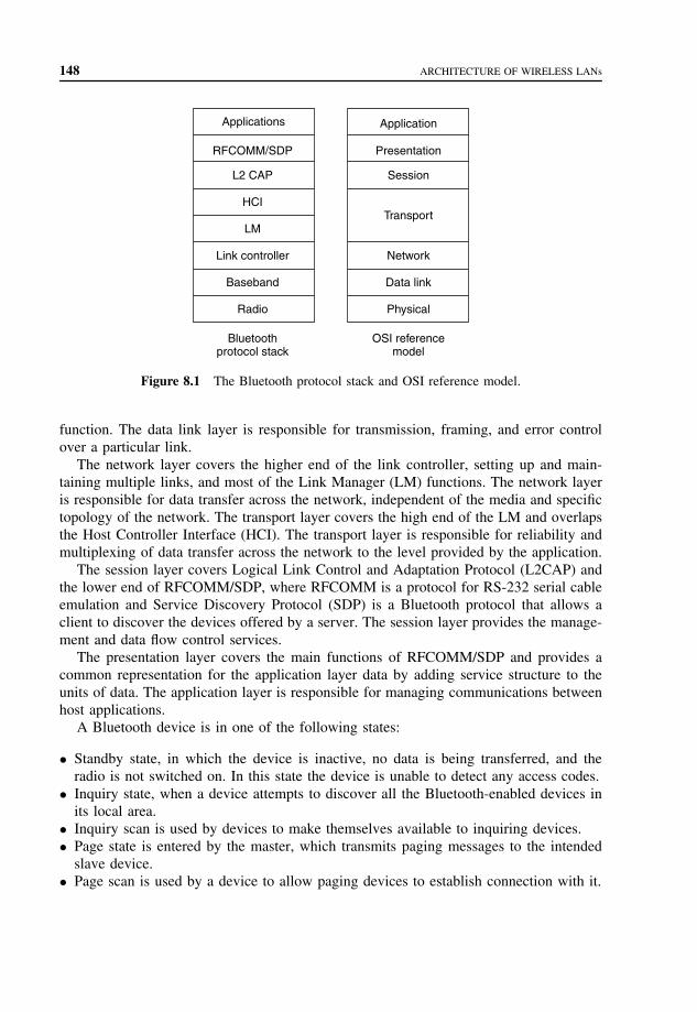
148 ARCHITECTURE OF WIRELESS LANs
Applications
RFCOMM/SDP
L2 CAP
HCI
LM
Link controller
Baseband
Radio
Application
Presentation
Session
Transport
Network
Data link
Physical
Bluetoothprotocol stack
OSI referencemodel
Figure 8.1 The Bluetooth protocol stack and OSI reference model.
function. The data link layer is responsible for transmission, framing, and error controlover a particular link.
The network layer covers the higher end of the link controller, setting up and main-taining multiple links, and most of the Link Manager (LM) functions. The network layeris responsible for data transfer across the network, independent of the media and specifictopology of the network. The transport layer covers the high end of the LM and overlapsthe Host Controller Interface (HCI). The transport layer is responsible for reliability andmultiplexing of data transfer across the network to the level provided by the application.
The session layer covers Logical Link Control and Adaptation Protocol (L2CAP) andthe lower end of RFCOMM/SDP, where RFCOMM is a protocol for RS-232 serial cableemulation and Service Discovery Protocol (SDP) is a Bluetooth protocol that allows aclient to discover the devices offered by a server. The session layer provides the manage-ment and data flow control services.
The presentation layer covers the main functions of RFCOMM/SDP and provides acommon representation for the application layer data by adding service structure to theunits of data. The application layer is responsible for managing communications betweenhost applications.
A Bluetooth device is in one of the following states:
• Standby state, in which the device is inactive, no data is being transferred, and theradio is not switched on. In this state the device is unable to detect any access codes.
• Inquiry state, when a device attempts to discover all the Bluetooth-enabled devices inits local area.
• Inquiry scan is used by devices to make themselves available to inquiring devices.• Page state is entered by the master, which transmits paging messages to the intended
slave device.• Page scan is used by a device to allow paging devices to establish connection with it.

BLUETOOTH 149
• Connection–Active is a state in which the slave moves to the master’s frequency hopand timing sequence by switching to the master’s clock.
• Connection–Hold mode allows the device to maintain its active member address whileceasing to support ACL traffic for a certain time to free bandwidth for other operationssuch as scanning, paging, inquiry, or low-power sleep.
• Connection–Sniff mode allows the device to listen for traffic by using a predefinedslot time.
• Connection–Park mode allows the device to enter low-power sleep mode by giving upits active member address and listening for traffic only occasionally.
The SDP is used for device discovery. The messages exchanged between two devicesduring inquiry and inquiry scan are shown in Figure 8.2. The inquiring device calls out bytransmitting Identifier (ID) packets containing an IAC. When a scanning device first hearsan inquiry, it waits for a random period and then reenters the scanning state, listeningonce more for another ID. This time, if it hears the inquiry, it replies with the FrequencyHop Synchronization (FHS) packet. Several devices can respond to an inquiry but theirresponses are spaced out randomly and do not interfere. The inquirer must keep inquiringfor longer than the range of the random period.
Start inquiry
HCI commandsand events
Basebandpacket
exchange
HCI commandsand events
Inqu
iring
dev
ice
Inqu
iry
scan
ning
dev
ice
Inquiry result
Inquiry complete
FHS packet
ID packet with inquiryaccess code
ID packet with inquiryaccess code
ID packet with inquiryaccess code
Random delaybefore response
Timer periodicallyinitiates inquiry
scan
Configure scan (inquiry)
Enable scan (inquiry)
•••
•
•
•••
•
•
Figure 8.2 Message sequence chart for inquiry and inquiry scan.

150 ARCHITECTURE OF WIRELESS LANs
Connection accept Connection complete
Create connectionrequest
Connection request
Configure scan (page)
Enable scan (page)
LMP link configuration
ACL packet (NULL)
ACL packet (POLL)
ID packet with slave's access code
ID packet with slave's access code
ID packet with slave's access code
ID packet with slave's access code
FHS packet
Both devices move to paging device's hop sequence
HCI commandsand events
HCI commandsand events
Basebandpacket
exchange
Timer periodicallyinitiates page scan
•••
Figure 8.3 Message sequence chart for paging and page scanning.
A paging procedure is used to establish connection between devices. Figure 8.3 showsthe messages exchanged between two devices during connection establishment. A devicesends out a series of paging ID packets based on the paged device’s address. The page-scanning device is configured to carry out periodic page scans of a specified duration andat a specified interval. The scanning device starts a timer and a periodic scan when thetimer elapses. The pager transmits ID packets with the page scanner’s address. If the pagescanner is scanning during this time, it will trigger and receive the ID packet replyingwith another ID, using its own address. The page scanner acknowledges the FHS packetby replying with another ID. The page scanner can extract the necessary parameters,like Bluetooth clock and active member address, from the FHS packet, to use in thenew connection. The page scanner calculates the pager’s hop sequence and moves to theconnection hop sequence with the pager as master and page scanner as slave. The mastersends a POLL packet to check that the frequency hop sequence switch has happenedcorrectly. The switch must then respond with an ACL packet. Then follows various LMPlink configuration packets exchange. If required, master and slave can agree to swap theroles in a master/slave switch.

BLUETOOTH 151
A connection between a host and a Bluetooth device is established in the following steps:
1. Host requests an inquiry.2. Inquiry is sent using the inquiry hopping sequence.3. Inquiry scanning devices respond to the inquiry scan with FHS packets that contain
all the information needed to connect with them.4. The contents of the FHS packets are passed back to the host.5. The host requests connection to one of the devices that responded to the inquiry.6. Paging is used to initiate a connection with the selected device.7. If the selected device is page scanning, it responds to the page.8. If the page-scanning device accepts the connection, it will start hopping using the
master’s frequency hopping sequence and timing.
The following operations are managed by the link manager (LM), which translates theHost Controller Interface (HCI) commands.
1. Attaching slaves to a piconet and allocating their active member addresses2. Breaking connections to detach slaves from a piconet3. Configuring the link including controlling master/slave switches in which both devices
must simultaneously change roles4. Establishing ACL data and SCO voice links5. Putting connections into low power modes: hold, sniff, and park6. Controlling test modes.
In Bluetooth standard the HCI uses command packets for the host to control the module.The module uses event packets to inform the host of changes in the lower layers. Thedata packets are used to pass voice and data between host and module. The transportlayers carry HCI packets.
The host controls a Bluetooth module by using the following HCI commands:
1. Link control, for instance, setting up, tearing down, and configuring links.2. Power-saving modes and switching of the roles between master and slave.3. Direct access to information on the local Bluetooth module and access to information
on remote devices by triggering LMP exchanges.4. Control of baseband features, for instance, timeouts.5. Retrieving status information on a module.6. Invoking Bluetooth test modules for factory testing and for Bluetooth qualification.
L2CAP sends data packets to HCI or to LM. The functions of L2CAP include
• multiplexing between higher layer protocols that allows them to share lower layer links;• segmentation and reassembly to allow transfer of larger packets than those that lower
layers support;• group management by providing one-way transmission to a group of other Blue-
tooth devices;• quality of service management for higher layer protocols.

152 ARCHITECTURE OF WIRELESS LANs
L2CAP provides the following facilities needed by higher layer protocols:
• Establishing links across underlying ACL channels using L2CAP signals;• Multiplexing between different higher layer entities by assigning each one its own
connection ID;• Providing segmentation and reassembly facilities to allow large packets to be sent across
Bluetooth connections.
RFCOMM is a protocol for RS-232 serial cable emulation. It is a reliable transportprotocol with framing, multiplexing, and providing modem status, remote line status,remote port settings, and parameter negotiation. RFCOMM supports devices with internalemulated serial port and intermediate devices with physical serial port. RFCOMM com-municates with frames that are carried in the data payload in L2CAP packets. An L2CAPconnection must be set up before an RFCOMM connection can be set up. RFCOMM isbased on the Global System for Mobile communications (GSM) 07.10 standard with afew minor differences between Bluetooth and GSM cellular phone connections.
SDP server is a Bluetooth device offering services to other Bluetooth devices. EachSDP server maintains its own database containing information about those services. AnL2CAP channel must be established between SDP client and server, which uses a protocolservice multiplexor reserved for SDP. After the SDP information has been retrieved fromthe server, the client must establish a separate connection to use the service. Serviceshave Universally Unique Identifiers (UUIDs) that describe them.
8.5.2 B luetooth applications
Bluetooth can be used as a bearer layer in WAP architecture. A WAP server can bepreconfigured with the Bluetooth device address of a WAP server in range, or a WAPclient can find it by conducting an inquiry and then use service discovery to find a WAPserver. The WAP client needs to use SDP to find the RFCOMM server number allocated toWAP services. The WAP server’s service discovery record identifies whether the serviceis a proxy used to access files on other devices, an origin server, which provides itsown files, or both. The provided information includes home URL, service name, and aset of parameters needed to connect to the WAP service, which are the port numbersallocated to the various layers of the WAP stack. Once the service discovery informationhas been retrieved, an L2CAP link for RFCOMM is established and a WSP session isset up over this link. The URLs can be requested by Wireless Application Environment(WAE) across WSP.
The WAP layers use User Datagram Protocol (UDP), Internet Protocol (IP), and Point-to-Point Protocol (PPP), which allow datagrams to be sent across Bluetooth’s RFCOMMserial port emulation layer. The WAP components used above the Bluetooth protocolstack are shown in Figure 8.4.
Telephony Control protocol Specification (TCS) provides call control signaling to estab-lish voice and data calls between Bluetooth devices. TCS signals use L2CAP channel witha Protocol and Service Multiplexor (PSM) reserved for TCS. A separate bearer channelis established to carry the call, for example, an SCO channel or an ACL channel. TCS

BLUETOOTH 153
WAE
WSP
WTP
WTLS
UDP
IP
PPP
RFCOMM/SDP
L2 CAP
HCI
LM
Link controller
Radio
WAP
Bluetooth
Figure 8.4 WAP on the Bluetooth protocol stack.
does not define handover of calls from one device to another and does not provide amechanism for groups of devices to enter into conference calls; only point-to-point linksare supported.
Bluetooth profiles are illustrated in Figure 8.5. The Generic Access Profile (GAP) isthe basic Bluetooth profile used by the devices to establish baseband links.
The serial port profile provides RS-232 serial cable emulation for Bluetooth devices.It provides a simple, standard way for applications to interoperate, for example, legacyapplications do not need to be modified to use Bluetooth; they can treat Bluetooth link as aserial cable link. The serial port profile is based on the GSM standard GSM 07.10, whichallows multiplexing of serial connections over one serial link. It supports a communicationend point, for instance, a laptop. It also supports intermediate devices, which form partof a communications link, for instance, modems.
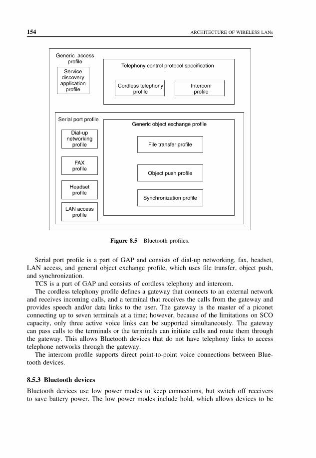
154 ARCHITECTURE OF WIRELESS LANs
Telephony control protocol specification
Cordless telephonyprofile
Intercomprofile
Generic object exchange profile
File transfer profile
Object push profile
Synchronization profile
Serial port profile
Dial-upnetworking
profile
FAXprofile
Headsetprofile
LAN accessprofile
Generic accessprofile
Servicediscovery
applicationprofile
Figure 8.5 Bluetooth profiles.
Serial port profile is a part of GAP and consists of dial-up networking, fax, headset,LAN access, and general object exchange profile, which uses file transfer, object push,and synchronization.
TCS is a part of GAP and consists of cordless telephony and intercom.The cordless telephony profile defines a gateway that connects to an external network
and receives incoming calls, and a terminal that receives the calls from the gateway andprovides speech and/or data links to the user. The gateway is the master of a piconetconnecting up to seven terminals at a time; however, because of the limitations on SCOcapacity, only three active voice links can be supported simultaneously. The gatewaycan pass calls to the terminals or the terminals can initiate calls and route them throughthe gateway. This allows Bluetooth devices that do not have telephony links to accesstelephone networks through the gateway.
The intercom profile supports direct point-to-point voice connections between Blue-tooth devices.
8.5.3 Bluetooth devices
Bluetooth devices use low power modes to keep connections, but switch off receiversto save battery power. The low power modes include hold, which allows devices to be
BLUETOOTH 155
inactive for a single short period; sniff that allows devices to be inactive except forperiodic sniff slots; and park, which is similar to sniff, except that parked devices giveup their active member address.
Hold mode is used to stop ACL traffic for a specified period of time, but SCO traffic isnot affected. Master and slave can force or request hold mode. A connection enters holdmode due to a request from the local host, or when a link manager at the remote end ofa connection requests it to hold, or when the local link manager autonomously decidesto put the connection in hold mode. A device enters hold mode when all its connectionsare in hold mode.
Sniff mode is used to save power on low data rate links and reduces traffic to periodicsniff slots. A device in sniff mode only wakes up periodically in prearranged sniff slots.The master and slave must negotiate the timing of the first sniff slot and the interval atwhich further sniff slots follow. They also negotiate the window in which the sniffingslave will listen for transmissions and the sniff timeout. A device enters sniff mode dueto a request from its own host, or when a link manager at the remote end of a connectionrequests or forces it to enter sniff mode. A master can force a slave into sniff mode andgive permission to a slave, which requests to enter sniff mode.
A device entering park mode gives up its active member address and ceases to bean active member of the piconet. This device cannot transmit and cannot be addresseddirectly by the master; however, it wakes up periodically and listens for broadcasts, whichcan be used to unpark it. At prearranged beacon instants, a device in park mode wakesperiodically to listen for transmissions from the master during a series of beacon slots.Park mode allows the greatest power saving.
Quality of service (QoS) capabilities include data rate, delay, and reliability and areprovided by the link manager, which chooses packet types, sets polling intervals, allocatesbuffers, link bandwidth, and makes decisions about performing scans. Link managersnegotiate peer to peer to ensure that QoS is coordinated at both ends of a link. For unicast(point-to-point), a reliable link is provided by the receiver acknowledging packets. Thepackets not acknowledged are retransmitted. Broadcast packets are not acknowledged, andto provide a reliable link, a Bluetooth device can be set to retransmit broadcast packets acertain number of times.
Figure 8.6 shows Bluetooth devices with different capabilities. These devices are per-sonal devices, point-to-point devices, point-to-multipoint devices, and scatternet devices.
A personal device connects only to one other preset device. If another device attemptsto connect to a personal device, it refuses the LMP connection request message.
A point-to-point device supports only one ACL data link at a time. When a Bluetoothdevice inquires for other devices in the area, it receives FHS packets, which contain all theinformation required to connect to the devices, including the clock offset. A point-to-pointdevice must keep a database of the devices it has discovered.
Point-to-multipoint device can establish links to several devices. This device musthandle QoS balancing between the links through allocation of bandwidth to each link.Bandwidth requirements are received from the higher layer protocols and lower layerssend QoS violations to the higher layers.
A scatternet is a group of linked piconets joined by common members that can eitherbe slaves on both piconets or a master of one piconet and a slave on another. Bandwidth

156 ARCHITECTURE OF WIRELESS LANs
Presetlink
Master
Master
Master
Master
Master Master
Master Master
Slave
Slave
Slave
Slave
Slave
SlaveSlave
Slave/master
Slave
Slave Slave
Slave
Slave
Slave
SlaveSlave
Ad hoclink
Personal Point-to-point Point-to-multipoint
Scatternet
Scatternet
Scatternet
Figure 8.6 Bluetooth devices with different capabilities.
is reduced in scatternet by the time taken to switch between piconets, which should bedone infrequently. Devices are absent from one piconet when present on the other, andthis absence should be managed if maximum efficiency is required. Managing piconetsinvolves calculation and negotiation of parameters for QoS, and possibly beacon slots,sniff slots, or hold times.
A device manager performs as an interpreter between applications and Bluetooth pro-tocols as shown in Figure 8.7. Applications requesting links and discovering devices usethe device manager, which also has the information about configuration control. A devicemanager handles set up, tear down, and configuration of the baseband links, QoS param-eters and trade-offs, management of higher layer links, device discovery, and informationcaching. The device manager has an interface to HCI, RFCOMM, and LC2CAP.

SUMMARY 157
MMI (Man−Machine Interface)
Configurationapplication Application Application
Device manager
SDP RFCOMM
Serial portapplication
HCI
L2 CAP
Baseband layer
Figure 8.7 Bluetooth protocol stack with device manager.
8.6 SUMMARY
The use of Spread Spectrum is especially important as it allows many more users to occupythe band at any given time and place than if they were all static on separate frequencies.With any radio system, one of the greatest limitations is available bandwidth, and so theability to have many users operate simultaneously in a given environment is critical forthe successful deployment of WLAN.
The application of Infrared is as a docking function and in applications in which thepower available is extremely limited, such as a pager or PDA.

158 ARCHITECTURE OF WIRELESS LANs
There are two methods of Spread Spectrum modulation: Direct Sequence Spread Spec-trum (DSSS) and Frequency Hopping Spread Spectrum (FHSS).
IEEE 802.11 appears to higher layers [Logical Link Control (LLC)] as an IEEE802 LAN, which requires that the IEEE 802.11 network handle station mobility withinthe MAC sublayer and meets the reliability assumptions that LLC makes about thelower layers.
In Bluetooth standard the HCI uses command packets for the host to control the module.The module uses event packets to inform the host of changes in the lower layers. Thedata packets are used to pass voice and data between host and module. The transportlayers carry HCI packets.
Bluetooth can be used as a bearer layer in WAP architecture. A WAP server can bepreconfigured with the Bluetooth device address of a WAP server in range, or a WAP clientcan find it by conducting an inquiry and then use service discovery to find a WAP server.
PROBLEMS TO CHAPTER 8
Architecture of wireless LANs
Learning objectives
After completing this chapter, you are able to
• demonstrate an understanding of wireless LANs;• explain the role of RF;• explain the role of IR;• explain the difference between DSSS and FHSS;• demonstrate an understanding of IEEE 802.11 WLAN architecture;• explain the role of STA;• explain the role of BSS and ESS;• explain the role of DS, DSM, and DSS;• demonstrate an understanding of Bluetooth architecture;• explain the states of a Bluetooth device;• explain how a connection is established between a host and Bluetooth device;• explain the role of the HCI;• explain the functions of L2CAP.
Practice problems
8.1: What are the WLAN’s operating speeds?8.2: What is the radio frequency (RF) band in which the LANs operate?8.3: Where is RF used?8.4: Where is IR used?8.5: What is the function of DSSS?8.6: What is the function of FHSS?8.7: What is the addressable unit in IEEE 802.11?

PROBLEMS TO CHAPTER 8 159
8.8: What is BSS?8.9: What is the architecture of the DS?
8.10: What is the role of a portal?8.11: What are the architectural services of IEEE 802.11?8.12: What are the possible states of a Bluetooth device?8.13: How is a connection between a host and Bluetooth device established?8.14: How does the host control a Bluetooth module?8.15: What are the functions of L2CAP?
Practice problem solutions
8.1: A WLAN is capable of operating at speeds in the range of 1, 2, or 11 Mbpsdepending on the actual system. These speeds are supported by the standard forWLAN networks defined by the international body, the IEEE.
8.2: WLAN communications take place in a part of the radio spectrum that is designatedas license-free. In this band, 2.4 to 2.5 GHz, users can operate without a licenseas long as they use equipment that has been type-approved for use in the license-free bands.
8.3: RF is very capable of being used for applications in which communications are notline-of-sight and are over longer distances. The RF signals travel through walls andcommunicate where there is no direct path between the terminals.
8.4: Infrared is primarily used for very short distance communications, less than 3 ftwhere there is an LOS connection. It is not possible for the Infrared light to penetrateany solid material; it is even attenuated greatly by window glass, so it is really nota useful technology in comparison to Radio Frequency for use in a WLAN system.The application of Infrared is as a docking function and in applications in whichthe power available is extremely limited such as a pager or PDA. The standard forsuch products is called Infrared Data Association (IrDA), which has been used byHewlett Packard, IBM, and others. This is found in many notebook and laptop PCsand allows a connectionless docking facility up to 1 Mbps to a desktop machineand up to two feet, line of sight.
8.5: A DSSS system takes a signal at a given frequency and spreads it across a bandof frequencies where the center frequency is the original signal. The spreadingalgorithm, which is the key to the relationship of the spread range of frequencies,changes with time in a pseudorandom sequence that appears to make the spreadsignal a random noise source.
8.6: Frequency Hopping Spread Spectrum (FHSS) is based on the use of a signal ata given frequency that is constant for a small amount of time and then moves toa new frequency. The sequence of different channels determined for the hoppingpattern, that is, where the next frequency will be to engage with this signal source,is pseudorandom.
8.7: In IEEE 802.11 the addressable unit is a station (STA), which is a message desti-nation, but not (in general) a fixed location. IEEE 802.11 handles both mobile andportable stations. MSs access the LAN while in motion, whereas a Portable Station(PS) can be moved between locations but it is used only at a fixed location. MSs
160 ARCHITECTURE OF WIRELESS LANs
are often battery powered, and power management is an important considerationsince we cannot assume that a station’s receiver will always be powered on.
8.8: The IEEE 802.11 architecture provides a WLAN supporting station mobility trans-parently to upper layers. The Basic Service Set (BSS) is the basic building blockconsisting of member stations remaining in communication. If a station moves outof its BSS, it can no longer directly communicate with other members of the BSS.
The IBSS is the most basic type of IEEE 802.11 LAN, and may consist of atleast two stations that can communicate directly. This LAN is formed only as longas it is needed, and is often referred to as an ad hoc network. The associationbetween an STA and a BSS is dynamic since STAs turn on and off, come withinrange and go out of range.
8.9: A BSS may form the Distribution System (DS), which is an architectural componentused to interconnect BSSs. IEEE 802.11 logically separates the Wireless Medium(WM) from the Distribution System Medium (DSM). Each logical medium is usedfor different purposes by a different component of the architecture. The IEEE 802.11LAN architecture is specified independently of the physical characteristics of anyspecific implementation. The DS enables mobile device support by providing thelogical services necessary to handle address-to-destination mapping and seamlessintegration of multiple BSSs. An Access Point (AP) is an STA that provides accessto the DS by providing DS services in addition to acting as an STA. The datamove between a BSS and the DS via an AP. All APs are also STAs and they areaddressable entities. The addresses used by an AP for communication on the WMand on the DSM are not necessarily the same.
The DS and BSSs allow IEEE 802.11 to create a wireless network of arbitrarysize and complexity called the Extended Service Set (ESS) network. The ESS net-work appears the same to an LLC layer as an IBSS network. Stations within anESS may communicate and MSs may move from one BSS to another (within thesame ESS) transparently to LLC.
8.10: A portal is the logical point at which MAC Service Data Units (MSDUs) from anintegrated non-IEEE 802.11 LAN enter the IEEE 802.11 DS. All data from non-IEEE 802.11 LANs enter the IEEE 802.11 architecture via a portal, which provideslogical integration between the IEEE 802.11 architecture and existing wired LANs.A device may offer both the functions of an AP and a portal, for example, when aDS is implemented from IEEE 802 LAN components.
8.11: Architectural services of IEEE 802.11 are as follows: authentication, association,deauthentication, disassociation, distribution, integration, privacy, reassociation, andMSDU delivery. These services are provided either by stations as the Station Service(SS) or by the DS as the Distribution System Service (DSS).
The SS includes authentication, deauthentication, privacy, and MSDU delivery.The SS is present in every IEEE 802.11 station, including APs and is specified foruse by MAC sublayer entities.
The DSSs include association, disassociation, distribution, integration, and reas-sociation. The DSSs are provided by the DS and accessed by an AP, whichis an STA that also provides DSSs. DSSs are specified for use by MAC sub-layer entities.

PROBLEMS TO CHAPTER 8 161
8.12: A Bluetooth device is in one of the following states:
• Standby state, in which the device is inactive, no data is being transferred, andthe radio is not switched on. In this state the device is unable to detect anyaccess codes.
• Inquiry state, when a device attempts to discover all the Bluetooth-enableddevices in its local area.
• Inquiry scan is used by devices to make themselves available to inquiring devices.• Page state is entered by the master, which transmits paging messages to the
intended slave device.• Page scan is used by a device to allow paging devices to establish connection
with it.• Connection–Active is a state in which the slave moves to the master’s frequency
hop and timing sequence by switching to the master’s clock.• Connection–Hold mode allows the device to maintain its active member address
while ceasing to support ACL traffic for a certain time to free bandwidth forother operations such as scanning, paging, inquiry, or low-power sleep.
• Connection–Sniff mode allows the device to listen for traffic by using a prede-fined slot time.
• Connection–Park mode allows the device to enter low-power sleep mode bygiving up its active member address and listening for traffic only occasionally.
8.13: A connection between a host and Bluetooth device is established in the follow-ing steps:
1. Host requests an inquiry.2. Inquiry is sent using the inquiry hopping sequence.3. Inquiry scanning devices respond to the inquiry scan with FHS packets that
contain all the information needed to connect with them.4. The contents of the FHS packets are passed back to the host.5. The host requests connection to one of the devices that responded to the inquiry.6. Paging is used to initiate a connection with the selected device.7. If the selected device is page scanning, it responds to the page.8. If the page-scanning device accepts the connection, it will start hopping using
the master’s frequency hopping sequence and timing.
8.14: The host controls a Bluetooth module by using the following HCI commands:
1. Link control, for instance, setting up, tearing down, and configuring links.2. Power-saving modes and switching of the roles between master and slave.3. Direct access to information on the local Bluetooth module and access to infor-
mation on remote devices by triggering LMP exchanges.4. Control of baseband features, for instance, timeouts.5. Retrieving status information on a module.6. Invoking Bluetooth test modules for factory testing and for Bluetooth qualification.
8.15: Logical Link Control and Adaptation Protocol (L2CAP) send data packets to HCIor to LM. The functions of L2CAP include

162 ARCHITECTURE OF WIRELESS LANs
• multiplexing between higher layer protocols that allow them to share lowerlayer links;
• segmentation and reassembly to allow transfer of larger packets than those thatlower layers support;
• group management by providing one-way transmission to a group of other Blue-tooth devices; and
• Quality-of-service management for higher layer protocols.
L2CAP provides the following facilities needed by higher layer protocols:
• Establishing links across underlying ACL channels using L2CAP signals.• Multiplexing between different higher layer entities by assigning each one its
own connection ID.• Providing segmentation and reassembly facilities to allow large packets to be
sent across Bluetooth connections.

9
Routing protocols in mobileand wireless networks
Mobile and wireless networks allow the users to access information and services elec-tronically, regardless of their geographic location. There are infrastructured networks andinfrastructureless (ad hoc) networks. Infrastructured network consists of a network withfixed and wired gateways. A mobile host communicates with a Base Station (BS) withinits communication radius. The mobile unit can move geographically while it is commu-nicating. When it goes out of range of one BS, it connects with a new BS and startscommunicating through it by using a handoff. In this approach, the BSs are fixed.
In contrast to infrastructure-based networks, in ad hoc networks all nodes are mobileand can be connected dynamically in an arbitrary manner. All nodes of these networksbehave as routers and take part in discovery and maintenance of routes to other nodes inthe network. Ad hoc networks are very useful in emergency search-and-rescue operations,meetings, or conventions in which persons wish to quickly share information and dataacquisition operations in inhospitable terrain.
An ad hoc network is a collection of mobile nodes forming a temporary networkwithout the aid of any centralized administration or standard support services regularlyavailable in conventional networks. We assume that the mobile hosts use wireless radiofrequency transceivers as their network interface, although many of the same principleswill apply to infrared and wire-based networks. Some form of routing protocol is necessaryin these ad hoc networks since two hosts wishing to exchange packets may not be ableto communicate directly.
Wireless network interfaces usually operate at significantly slower bit rates than theirwire-based counterparts. Frequent flooding of packets throughout the network, a mecha-nism many protocols require, can consume significant portions of the available networkbandwidth. Ad hoc routing protocols must minimize bandwidth overhead at the same timeas they enable routing.
Ad hoc networks must deal with frequent changes in topology. Mobile nodes changetheir network location and link status on a regular basis. New nodes may unexpectedly join
Mobile Telecommunications Protocols For Data Networks. Anna HacCopyright 2003 John Wiley & Sons, Ltd.
ISBN: 0-470-85056-6

164 ROUTING PROTOCOLS IN MOBILE AND WIRELESS NETWORKS
the network or existing nodes may leave or be turned off. Ad hoc routing protocols mustminimize the time required to converge after the topology changes. A low convergencetime is more critical in ad hoc networks because temporary routing loops can result inpackets being transmitted in circles, further consuming valuable bandwidth.
The routing protocols meant for wired networks cannot be used for mobile ad hocnetworks because of the mobility of networks. The ad hoc routing protocols can bedivided into two classes: table-driven and on-demand routing, on the basis of when andhow the routes are discovered. In table-driven routing protocols, consistent and up-to-date routing information to all nodes is maintained at each node, whereas in on-demandrouting the routes are created only when desired by the source host. We discuss currenttable-driven protocols as well as on-demand protocols.
9.1 TABLE-DRIVEN ROUTING PROTOCOLS
In table-driven routing protocols, each node maintains one or more tables containingrouting information to every other node in the network. All nodes update these tables soas to maintain a consistent and up-to-date view of the network. When the network topologychanges, the nodes propagate update messages throughout the network in order to maintaina consistent and up-to-date routing information about the whole network. These routingprotocols differ in the method by which the information regarding topology changes isdistributed across the network and in the number of necessary routing-related tables.
9.1.1 Destination-sequenced distance-vector routing
Destination-Sequenced Distance-Vector Routing (DSDV) is an adoption of a conven-tional routing protocol to ad hoc networks. DSDV is based on the Routing InformationProtocol (RIP) used in parts of the Internet. Consequently, DSDV only makes use ofbidirectional links.
In DSDV, packets are routed between nodes of an ad hoc network using a RoutingTable (RT) stored at each node. Each RT at each node contains a list of the addresses ofevery other node in the network. Along with each node’s address, the table contains theaddress of the next hop for a packet to take in order to reach the node.
DSDV generates and maintains the RTs. Every time the network topology changes,the RT in every node needs to be updated. In addition to the destination address andnext hop address, RTs maintain the route metric (the number of hops) and the routesequence number.
Periodically, or immediately when network topology changes are detected, each nodewill broadcast an RT update packet. The update packet starts out with a metric of one.This signifies to each receiving neighbor that it is one hop away from the node. Theneighbors will increment this metric and then retransmit the update packet. This processrepeats itself until every node in the network has received a copy of the update packetwith a corresponding metric. If a node receives duplicate update packets, the node willonly consider the update packet with the smallest metric and ignore the remaining ones.
TABLE-DRIVEN ROUTING PROTOCOLS 165
To distinguish stale update packets from valid ones, each update packet is tagged by theoriginal node with a sequence number. The sequence number is a monotonically increasingnumber that uniquely identifies each update packet from a given node. Consequently, ifa node receives an update packet from another node, the sequence number must be equalto or greater than the sequence number already in the RT; otherwise the update packet isstale and ignored. If the sequence number matches the sequence number in the RT, thenthe metric is compared and updated.
Each time an update packet is forwarded, the packet not only contains the address ofthe destination but it also contains the address of the transmitting node. The address ofthe transmitting node is entered into the RT as the next hop. The update packets with thehigher sequence numbers are always entered into the RT, regardless of whether they havea higher metric or not.
Each node must periodically transmit its entire RT to its neighbors using update pack-ets. The neighbors will update their tables on the basis of this information, if required.Likewise, each node will listen to its neighbors update packets and update its own RT.
Mobile nodes cause broken links as they move from place to place. The broken linkmay be detected by the communication hardware, or it may be inferred if no broadcastshave been received for a while from a former neighbor. A broken link is described ashaving a metric of infinity. Since this qualifies as a substantial route change, the detectingnode will broadcast an update message for the lost destination. This update message willhave a new sequence number and a metric of infinity. This will essentially cause the RTentries for the lost node to be flushed from the network. Routes to the lost node will beestablished again when the lost node sends out its next broadcast.
To avoid nodes and their neighbors generating conflicting sequence numbers whenthe topology changes, nodes only generate even sequence numbers for themselves, andneighbors responding to link changes only generate odd sequence numbers.
DSDV is based on a conventional routing protocol, RIP, adopted for use in ad hocnetworks. Routing is achieved by using RTs maintained by each node. The bulk of thecomplexity in DSDV is in generating and maintaining these RTs.
DSDV requires nodes to periodically transmit RT update packets, regardless of networktraffic. These update packets are broadcast throughout the network so every node in thenetwork knows how to reach every other node. As the number of nodes in the networkgrows, the size of the RTs and the bandwidth required to update them also grows. Thisoverhead is DSDV’s main weakness, as Broch et al. found in their simulations of 50-nodenetworks. Furthermore, whenever the topology changes, DSDV is unstable until updatepackets propagate throughout the network. Broch found DSDV to be the most difficult indealing with high rates of node mobility.
Every mobile station maintains an RT that lists all available destinations, the number ofhops to reach the destination, and the sequence number assigned by the destination node.The sequence number is used to distinguish stale routes from new ones and thus avoidthe formation of loops. The stations periodically transmit their RTs to their immediateneighbors. A station also transmits its RT if a significant change has occurred in itstable from the last update sent. Thus, the update is both time-driven and event-driven.The RT updates can be sent in two ways: a full dump or an incremental update. A fulldump sends the full RT to the neighbors and could span many packets, whereas in an

166 ROUTING PROTOCOLS IN MOBILE AND WIRELESS NETWORKS
incremental update, only those entries from the RT are sent that have a metric changesince the last update, and they must fit in a packet. If there is space in the incrementalupdate packet, then those entries may be included whose sequence number has changed.When the network is relatively stable, incremental updates are sent to avoid extra trafficand full dumps are relatively infrequent. In a fast-changing network, incremental packetscan grow, and full dumps will be more frequent. Each route update packet, in addition tothe RT information, also contains a unique sequence number assigned by the transmitter.The route labeled with the highest (i.e., the most recent) sequence number is used. Iftwo routes have the same sequence number, then the route with the best metric (i.e., theshortest route) is used. On the basis of the past history, the stations estimate the settlingtime of routes. The stations delay the transmission of a routing update by settling time soas to eliminate those updates that would occur if a better route was found very soon.
9.1.2 The wireless routing protocol
The Wireless Routing Protocol (WRP) is a table-based distance-vector routing protocol.Each node in the network maintains a Distance table, an RT, a Link-cost table, and aMessage Retransmission List (MRL). The Distance table of a node x contains the distanceof each destination node y via each neighbor z of x. It also contains the downstreamneighbor of z through which this path is realized. The RT of node x contains the distanceof each destination node y from node x, the predecessor and the successor of node x
on this path. It also contains a tag to identify if the entry is a simple path, a loop, orinvalid. Storing predecessor and successor in the table is beneficial in detecting loopsand avoiding counting-to-infinity problems. The Link-cost table contains cost of link toeach neighbor of the node and the number of timeouts since an error-free message wasreceived from that neighbor. The MRL contains information to let a node know whichof its neighbors has not acknowledged its update message and to retransmit the updatemessage to that neighbor.
Nodes exchange RTs with their neighbors using update messages periodically as wellas on link changes. The nodes present on the response list of update message (formedusing MRL) are required to acknowledge the receipt of the update message. If there isno change in RT since the last update, the node is required to send an idle Hello messageto ensure connectivity. On receiving an update message, the node modifies its distancetable and looks for better paths using new information. Any new path so found is relayedback to the original nodes so that they can update their tables. The node also updates itsRT if the new path is better than the existing path. On receiving an AcknowledgementACK, the node updates its MRL. A unique feature of this algorithm is that it checksthe consistency of all its neighbors every time it detects a change in link of any of itsneighbors. A consistency check in this manner helps eliminate looping situations in abetter way and it also has fast convergence.
9.1.3 Global state routing
Global State Routing (GSR) is similar to DSDV. It takes the idea of link state routingbut improves it by avoiding flooding of routing messages. In this algorithm, each node

TABLE-DRIVEN ROUTING PROTOCOLS 167
maintains a Neighbor list, a Topology table, a Next Hop table, and a Distance table.Neighbor list of a node contains the list of its neighbors (here all nodes that can be heardby a node are assumed to be its neighbors). For each destination node, the Topology tablecontains the link state information as reported by the destination and the timestamp of theinformation. For each destination, the Next Hop table contains the next hop to which thepackets for this destination must be forwarded. The Distance table contains the shortestdistance to each destination node.
The routing messages are generated on a link change as in link state protocols. Onreceiving a routing message, the node updates it’s Topology table if the sequence numberof the message is newer than the sequence number stored in the table. After this, the nodereconstructs its RT and broadcasts the information to its neighbors.
9.1.4 Fisheye state routing
Fisheye State Routing (FSR) is an improvement of GSR. The large size of update messagesin GSR wastes a considerable amount of network bandwidth. In FSR, each update messagedoes not contain information about all nodes. Instead, it exchanges information aboutcloser nodes more frequently than it does about farther nodes, thus reducing the updatemessage size. Each node receives accurate information about neighbors, and the detailand accuracy of information decreases as the distance from the node increases. The scopeis defined in terms of the nodes that can be reached in a certain number of hops. Thecenter node has the most accurate information about the other nodes. Even though a nodedoes not have accurate information about distant nodes, the packets are routed correctlybecause the route information becomes more and more accurate as the packet movescloser to the destination. FSR scales well to large networks as the overhead is controlledin this scheme.
9.1.5 Hierarchical state routing
The characteristic feature of Hierarchical State Routing (HSR) is multilevel clusteringand logical partitioning of mobile nodes. The network is partitioned into clusters anda cluster head elected as in a cluster-based algorithm. In HSR, the cluster heads againorganize themselves into clusters and so on. The nodes of a physical cluster broadcasttheir link information to each other. The cluster head summarizes its cluster’s informationand sends it to the neighboring cluster heads via the gateway. These cluster heads aremembers of the cluster on a level higher and they exchange their link information as wellas the summarized lower-level information among themselves and so on. A node at eachlevel floods to its lower level the information that it obtains after the algorithm has runat that level. The lower level has a hierarchical topology information. Each node has ahierarchical address. One way to assign hierarchical address is to use the cluster numberson the way from the root to the node. A gateway can be reached from the root via morethan one path; thus, a gateway can have more than one hierarchical address. A hierarchicaladdress is enough to ensure delivery from anywhere in the network to the host.
In addition, nodes are also partitioned into logical subnetworks and each node isassigned a logical address <subnet, host>. Each subnetwork has a Location Manage-ment Server (LMS). All the nodes of that subnet register their logical address with the
168 ROUTING PROTOCOLS IN MOBILE AND WIRELESS NETWORKS
LMS. The LMS advertise their hierarchical address to the top levels and the informationis sent down to all LMS too. The transport layer sends a packet to the network layer withthe logical address of the destination. The network layer finds the destination’s LMS fromits LMS and then sends the packet to it. The destination’s LMS forwards the packet tothe destination. Once the source and destination know each other’s hierarchical addresses,they can bypass the LMS and communicate directly. Since logical address/hierarchicaladdress is used for routing, it is adaptable to network changes.
9.1.6 Zone-based hierarchical link state routing protocol
In Zone-based Hierarchical Link State Routing Protocol (ZHLS), the network is dividedinto nonoverlapping zones. Unlike other hierarchical protocols, there is no zone-head.ZHLS defines two levels of topologies – node level and zone level. A node level topologytells how nodes of a zone are connected to each other physically. A virtual link betweentwo zones exists if at least one node of a zone is physically connected to some node ofthe other zone. Zone level topology tells how zones are connected together. There aretwo types of Link State Packets (LSP) as well – node LSP and zone LSP. A node LSP ofa node contains its neighbor node information and is propagated with the zone, whereasa zone LSP contains the zone information and is propagated globally. Each node hasfull node connectivity knowledge about the nodes in its zone and only zone connectivityinformation about other zones in the network. Given the zone id and the node id of adestination, the packet is routed on the basis of the zone id till it reaches the correct zone.Then in that zone, it is routed on the basis of the node id. A <zone id, node id> of thedestination is sufficient for routing, so it is adaptable to changing topologies.
9.1.7 Cluster-head gateway switch routing protocol
Cluster-head Gateway Switch Routing (CGSR) uses as basis the DSDV Routing algorithm.The mobile nodes are aggregated into clusters and a cluster head is elected. All nodesthat are in the communication range of the cluster head belong to its cluster. A gatewaynode is a node that is in the communication range of two or more cluster heads. Ina dynamic network, a cluster-head scheme can cause performance degradation due tofrequent cluster-head elections, so CGSR uses a Least Cluster Change (LCC) algorithm.In LCC, cluster-head change occurs only if a change in network causes two cluster heads tocome into one cluster, or one of the nodes moves out of the range of all the cluster heads.
The general algorithm works in the following manner: the source of the packet transmitsthe packet to its cluster head. From this cluster head, the packet is sent to the gatewaynode that connects this cluster head and the next cluster head along the route to thedestination. The gateway sends it to that cluster head and so on till the destination clusterhead is reached in this way. The destination cluster head then transmits the packet to thedestination.
Each node maintains a cluster member table that has mapping from each node toits respective cluster head. Each node broadcasts its cluster member table periodicallyand updates its table after receiving other node’s broadcasts using the DSDV algorithm.
ON-DEMAND ROUTING PROTOCOLS 169
In addition, each node also maintains an RT that determines the next hop to reach thedestination cluster.
On receiving a packet, a node finds the nearest cluster head along the route to thedestination according to the cluster member table and the RT. Then it consults its RT tofind the next hop in order to reach the cluster head selected in step one and transmits thepacket to that node.
9.2 ON-DEMAND ROUTING PROTOCOLS
In contrast to table-driven routing protocols, all up-to-date routes are not maintained atevery node; instead, the routes are created as and when they are required. When sourcewants to send a packet to destination, it invokes the route discovery mechanisms to findthe path to the destination. The route remains valid till the destination is reachable oruntil the route is no longer needed.
9.2.1 Temporally ordered routing algorithm
Temporally Ordered Routing Algorithm (TORA) is a distributed routing protocol basedon a link reversal algorithm. It is designed to discover routes on-demand, provide multipleroutes to a destination, establish routes quickly, and minimize communication overheadby localizing the reaction to topological changes when possible. Route optimality (theshortest-path routing) is considered of secondary importance, and longer routes are oftenused to avoid the overhead of discovering newer routes. It is also not necessary (nordesirable) to maintain routes between every source/destination pair at all times.
The actions taken by TORA can be described in terms of water flowing downhilltoward a destination node through a network of tubes that model the routing state of thenetwork. The tubes represent links between nodes in the network, the junctions of thetubes represent the nodes, and the water in the tubes represents the packets flowing towardthe destination. Each node has a height with respect to the destination that is computedby the routing protocol. If a tube between two nodes becomes blocked such that watercan no longer flow through it, the height of the nodes is set to a height greater than thatof any neighboring nodes, such that water will now flow back out of the blocked tubeand find an alternate path to the destination.
At each node in the network, a logically separate copy of TORA is run for eachdestination. When a node needs a route to a particular destination, it broadcasts a routequery packet containing the address of the destination. This packet propagates throughthe network until it reaches either the destination or an intermediate node having a routeto the destination. The recipient of the query packet then broadcasts an update packetlisting its height with respect to the destination (if the recipient is the destination, thisheight is 0). As this packet propagates back through the network, each node that receivesthe update sets its height to a value greater than the height of the neighbor from whichthe update was received. This has the effect of creating a series of directed links from theoriginal sender of the query to the node that initially generated the update.

170 ROUTING PROTOCOLS IN MOBILE AND WIRELESS NETWORKS
When a node discovers that a route to a destination is no longer valid, it adjusts itsheight so that it is at a local maximum with respect to its neighbors and transmits anupdate packet.
When a node detects a network partition, where a part of the network is physicallyseparated from the destination, the node generates a clear packet that resets the routingstate and removes invalid routes from the network.
TORA is a routing layer above network level protocol called the Internet Mobile Ad hocNetworking (MANET) Encapsulation Protocol (IMEP). IMEP is designed to support theoperation of many routing algorithms, network control protocols, or other upper layer pro-tocols intended for use in mobile ad hoc networks. The protocol incorporates mechanismsfor supporting link status and neighbor connectivity sensing, control packet aggregationand encapsulation, one-hop neighbor broadcast reliability, multipoint relaying, network-layer address resolution, and provides hooks for interrouter authentication procedures.
In TORA, each node must maintain a structure describing the node’s height as wellas the status of all connected links per connection supported by the network. Each nodemust also be in constant coordination with neighboring nodes in order to detect topologychanges and converge. As was found with DSDV, routing loops can occur while thenetwork is reacting to a change in topology.
TORA is designed to carry IP traffic over wireless links in an ad hoc network. On thebasis of simulation results by Park and Corson, it is best suited to large, densely packedarrays of nodes with very low node mobility. Broch et al. simulated node mobility andfound TORA to be encumbered by its layering on top of IMEP and that IMEP causedconsiderable congestion when TORA was trying to converge in response to node mobility.This resulted in TORA requiring between one to two orders of magnitude more routingoverhead than other ad hoc routing protocols investigated by Broch.
TORA is a highly adaptive, efficient, and scalable distributed routing algorithm basedon the concept of link reversal. TORA is proposed for highly dynamic mobile, multihopwireless networks. It is a source-initiated on-demand routing protocol. It finds multipleroutes from a source node to a destination node. The main feature of TORA is thatthe control messages are localized to a very small set of nodes near the occurrenceof a topological change. To achieve this, the nodes maintain routing information aboutadjacent nodes. The protocol has three basic functions: route creation, route maintenance,and route erasure.
Each node has a quintuple associated with it:
1. Logical time of a link failure2. The unique ID of the node that defined the new reference level3. A reflection indicator bit4. A propagation ordering parameter5. The unique ID of the node.
The first three elements collectively represent the reference level. A new referencelevel is defined each time a node loses its last downstream link due to a link failure. Thelast two values define a delta with respect to the reference level.
Route creation is done using Query (QRY) and Update (UPD) packets. The routecreation algorithm starts with the height (propagation ordering parameter in the quintuple)

ON-DEMAND ROUTING PROTOCOLS 171
of destination set to 0 and all other node’s height set to NULL (i.e., undefined). The sourcebroadcasts a QRY packet with the destination node’s identifier in it. A node with a non-NULL height responds with a UPD packet that has its height in it. A node receiving aUPD packet sets its height to one more than that of the node that generated the UPD. Anode with higher height is considered upstream and a node with lower height is considereddownstream. In this way, a Directed Acyclic Graph (DAG) is constructed from the sourceto the destination.
When a node moves, the DAG route is broken, and route maintenance is needed toreestablish a DAG for the same destination. When the last downstream link of a nodefails, it generates a new reference level. This results in the propagation of that referencelevel by neighboring nodes. Links are reversed to reflect the change in adapting to thenew reference level. This has the same effect as reversing the direction of one or morelinks when a node has no downstream links.
In the route erasure phase, TORA floods a broadcast clear packet (CLR) throughoutthe network to erase invalid routes.
In TORA, there is a potential for oscillations to occur, especially when multiple sets ofcoordinating nodes are concurrently detecting partitions, erasing routes, and building newroutes based on each other. Because TORA uses internodal coordination, its instabilityproblem is similar to the count-to-infinity problem in distance-vector routing protocols,except that such oscillations are temporary and route convergence will ultimately occur.
9.2.2 Dynamic source routing protocol
Dynamic Source Routing Protocol (DSRP) is designed to allow nodes to dynamicallydiscover a source route across multiple network hops to any destination in the ad hocnetwork. When using source routing, each packet to be routed carries in its header thecomplete, ordered list of nodes through which the packet must pass. A key advantage ofsource routing is that intermediate hops do not need to maintain routing information inorder to route the packets they receive, since the packets themselves already contain allthe necessary routing information.
DSRP does not require the periodic transmission of router advertisements or link statuspackets, reducing the overhead of DSRP. In addition, DSRP has been designed to computecorrect routes in the presence of unidirectional links.
Source routing is a routing technique in which the sender of a packet determines thecomplete sequence of nodes through which to forward the packet. The sender explicitlylists this path in the packet’s header, identifying each forwarding hop by the address ofthe next node to which the packet is to be transmitted on its way to the destination host.
DSRP is broken down into three functional components: routing, route discovery,and route maintenance. Route discovery is the mechanism by which a node wishingto send a packet to a destination obtains a path to the destination. Route maintenanceis the mechanism by which a node detects a break in its source route and obtains acorrected route.
To perform route discovery, the source node broadcasts a route request packet with arecorded source route listing. Each node that hears the route request forwards the request,if appropriate, adding its own address to the recorded source route in the packet. The route

172 ROUTING PROTOCOLS IN MOBILE AND WIRELESS NETWORKS
request packet propagates hop-by-hop outward from the source node until either the des-tination node is found or until another node is found that can supply a route to the target.
Nodes forward route requests if they are not the destination node and they are notalready listed as a hop in the route. In addition, each node maintains a cache of recentlyreceived route requests and does not propagate any copies of a route request packet afterthe first.
All source routes learned by a node are kept (memory permitting) in a route cache,which is used to further reduce the cost of route discovery. A node may learn of routesfrom virtually any packet the node forwards or overhears. When a node wishes to send apacket, it examines its own route cache and performs route discovery only if no suitablesource route is found.
Further, when a node receives a route request for which it has a route in its cache, itdoes not propagate the route request, but instead returns a route reply to the source node.The route reply contains the full concatenation of the recorded route from the source andthe cached route leading to the destination.
If a route request packet reaches the destination node, the destination node returns aroute reply packet to the source node with the full source to destination path listed.
Conventional routing protocols integrate route discovery with route maintenance bycontinuously sending periodic routing updates. If the status of a link or node changes, theperiodic updates will eventually reflect the change to all other nodes, presumably resultingin the computation of new routes. However, using route discovery, there are no periodicmessages of any kind from any of the mobile nodes. Instead, while a route is in use, theroute maintenance procedure monitors the operation of the route and informs the senderof any routing errors.
If a node along the path of a packet detects an error, the node returns a route errorpacket to the sender. The route error packet contains the addresses of the nodes at bothends of the hop in error. When a route error packet is received or overheard, the hopin error is removed from any route caches and all routes that contain this hop must betruncated at that point.
There are many methods of returning a route error packet to the sender. The easiest ofthese, which is only applicable in networks that only use bidirectional links, is to simplyreverse the route contained in the packet from the original host. If unidirectional linksare used in the network, the DSRP presents several alternative methods of returning routeerror packets to the sender.
Route maintenance can also be performed using end-to-end acknowledgments ratherthan the hop-by-hop acknowledgments described above. As long as a route exists by whichthe two end hosts can communicate, route maintenance is possible. In this case, existingtransport or application level replies or acknowledgments from the original destination, orexplicitly requested network level acknowledgments, may be used to indicate the statusof the node’s route to the other node.
Two sources of bandwidth overhead in DSRP are route discovery and route mainte-nance. They occur when new routes need to be discovered or when the network topologychanges. However, this overhead can be reduced by employing intelligent caching tech-niques in each node at the expense of memory and CPU resources. The remaining sourceof bandwidth overhead is the required source route header included in every packet.

ON-DEMAND ROUTING PROTOCOLS 173
Broch et al. found DSRP to perform the best of four protocols simulated. However,Broch simulated networks of 50 nodes. As the node count increases, the detrimentaleffects of route discovery and maintenance can be expected to grow.
DSRP is a source-routed on-demand routing protocol. A node maintains route cachescontaining the source routes that it is aware of. The node updates entries in the routecache as and when it learns about new routes.
The two major phases of the protocol are route discovery and route maintenance. Whenthe source node wants to send a packet to a destination, it looks up its route cache todetermine if it already contains a route to the destination. If it finds that an unexpiredroute to the destination exists, then it uses this route to send the packet. But if the nodedoes not have such a route, then it initiates the route discovery process by broadcastinga route request packet. The route request packet contains the address of the source, thedestination, and a unique identification number. Each intermediate node checks whetherit knows of a route to the destination. If it does not, it appends its address to the routerecord of the packet and forwards the packet to its neighbors. To limit the number ofroute requests propagated, a node processes the route request packet only if it has notalready seen the packet and its address is not present in the route record of the packet.
A route reply is generated when either the destination or an intermediate node withcurrent information about the destination receives the route request packet. A route requestpacket reaching such a node already contains, in its route record, the sequence of hopstaken from the source to this node.
As the route request packet propagates through the network, the route record is formed.If the route reply is generated by the destination, then it places the route record from routerequest packet into the route reply packet. On the other hand, if the node generating theroute reply is an intermediate node, then it appends its cached route to destination to theroute record of route request packet and puts that into the route reply packet. To sendthe route reply packet, the responding node must have a route to the source. If it has aroute to the source in its route cache, it can use that route. The reverse of route recordcan be used if symmetric links are supported. In case symmetric links are not supported,the node can initiate route discovery to source and piggyback the route reply on this newroute request.
DSRP uses two types of packets for route maintenance: Route Error packet andAcknowledgements. When a node encounters a fatal transmission problem at its datalink layer, it generates a Route Error packet. When a node receives a Route Error packet,it removes the hop in error from its route cache. All routes that contain the hop in error aretruncated at that point. Acknowledgment packets are used to verify the correct operationof the route links. This also includes passive acknowledgments in which a node hears thenext hop forwarding the packet along the route.
9.2.3 Cluster-based routing protocol
In Cluster-Based Routing Protocol (CBRP), the nodes are divided into clusters. To formthe cluster, the following algorithm is used. When a node comes up, it enters the undecidedstate, starts a timer, and broadcasts a ‘hello’ message. When a cluster head gets this hellomessage, it responds with a triggered hello message immediately. When the undecided

174 ROUTING PROTOCOLS IN MOBILE AND WIRELESS NETWORKS
node gets this message, it sets its state to member. If the undecided node times out, thenit makes itself the cluster head if it has a bidirectional link to some neighbor, otherwiseit remains in undecided state and repeats the procedure again. Cluster heads are changedas infrequently as possible.
Each node maintains a neighbor table. For each neighbor, the neighbor table of a nodecontains the status of the link (uni- or bidirectional) and the state of the neighbor (clusterhead or member). A cluster head keeps information about the members of its cluster andalso maintains a cluster adjacency table that contains information about the neighboringclusters. For each neighbor cluster, the table has entry that contains the cluster head andthe gateway through which the cluster can be reached.
When a source has to send data to destination, it floods route request packets (butonly to the neighboring cluster heads). On receiving the request, a cluster head checksto see if the destination is in its cluster. If it is, then the cluster head sends the requestdirectly to the destination, else it sends the request to all its adjacent cluster heads. Thecluster-heads address is recorded in the packet so a cluster head discards a request packetthat it has already seen. When the destination receives the request packet, it replies backwith the route that had been recorded in the request packet. If the source does not receivea reply within a time period, it backs off exponentially before trying to send the routerequest again.
In CBRP, routing is done using source routing. It also uses route shortening, that is,on receiving a source route packet, the node tries to find the farthest node in the routethat is its neighbor (this could have happened because of a topology change) and sendsthe packet to that node, thus reducing the route. If a node detects a broken link, whileforwarding the packet, it sends back an error message to the source and then uses localrepair mechanism. In local repair mechanism, when a node finds that the next hop isunreachable, it checks to see if the next hop can be reached through any of its neighborsor if the hop after the next hop can be reached through any other neighbor. If any one ofthe two works, the packet can be sent out over the repaired path.
The CBRP is a variation of the DSRP protocol. CBRP groups nodes located physicallyclose together into clusters. Each cluster elects a cluster head. The cluster head maintainscomplete knowledge of cluster membership and intercluster members (called gateways),which have access to neighboring clusters.
The main difference between DSRP and CBRP is during the route discovery operation.DSRP floods route query packets throughout the entire network. CBRP takes advantageof its cluster structure to limit the scope of route query flooding. In CBRP, only thecluster heads (and corresponding gateways) are flooded with query packets, reducing thebandwidth required by the route discovery mechanism.
CBRP depends on nodes transmitting periodic hello packets; a large part of the gainsmade by DSRP are because DSRP does not require periodic packets of any kind.
9.2.4 Ad hoc on-demand distance-vector routing
Ad hoc On-demand Distance-Vector Routing (AODV) is an improvement on the DSDValgorithm. AODV minimizes the number of broadcasts by creating routes on-demand asopposed to DSDV that maintains the list of all the routes. To find a path to the destination,

ON-DEMAND ROUTING PROTOCOLS 175
the source broadcasts a route request packet. The neighbors in turn broadcast the packetto their neighbors till it reaches an intermediate node that has a recent route informationabout the destination or till it reaches the destination. A node discards a route requestpacket that it has already seen. The route request packet uses sequence numbers to ensurethat the routes are loop-free and to make sure that if the intermediate nodes reply to routerequests, they reply with the latest information only.
When a node forwards a route request packet to its neighbors, it also records in itstables the node from which the first copy of the request came. This information is usedto construct the reverse path for the route reply packet. AODV uses only symmetric linksbecause the route reply packet follows the reverse path of route request packet. As theroute reply packet traverses back to the source, the nodes along the path enter the forwardroute into their tables.
If the source moves, then it can reinitiate route discovery to the destination. If oneof the intermediate nodes move, then the moved nodes neighbor realizes the link failureand sends a link failure notification to its upstream neighbors and so on till it reaches thesource upon which the source can reinitiate route discovery if needed.
AODV routing is essentially a combination of both DSRP and DSDV. It borrowsthe basic on-demand mechanism of route discovery and route maintenance from DSRP,plus the use of hop-by-hop routing, sequence numbers, and periodic update packetsfrom DSDV.
The main benefit of AODV over DSRP is that the source route does not need to beincluded with each packet. This results in a reduction of routing protocol overhead. AODVrequires periodic updates that, based on simulations by Broch, consume more bandwidththan is saved from not including source route information in the packets.
9.2.5 Signal stability-based adaptive routing
Signal Stability-Based Adaptive Routing (SSA) is a variant of the AODV protocol to takeadvantage of information available at the link level. Both the signal quality of links andlink congestion are taken into consideration when finding routes. It is assumed that linkswith strong signals will change state less frequently. By favoring these strong signal linksin route discovery, it is hoped that routes will survive longer and the number of routediscovery operations will be reduced. Link signal strength is measured when the nodestransmit periodic hello packets.
One important difference of SSA from AODV or DSRP is that paths with strong signallinks are favored over optimal paths. While this may make routes longer, it is hoped thatdiscovered routes will survive longer.
Signal Stability-based adaptive Routing protocol (SSR) is an on-demand routing pro-tocol that selects routes on the basis of the signal strength between nodes and a node’slocation stability. This route selection criterion has the effect of choosing routes thathave stronger connectivity. SSR is composed of two cooperative protocols: the DynamicRouting Protocol (DRP) and the Static Routing Protocol (SRP). The DRP maintains theSignal Stability Table (SST) and RT. The SST stores the signal strength of neighboringnodes obtained by periodic beacons from the link layer of each neighboring node. Signalstrength is either recorded as a strong or weak channel. All transmissions are received

176 ROUTING PROTOCOLS IN MOBILE AND WIRELESS NETWORKS
by DRP and processed. After updating the appropriate table entries, the DRP passes thepacket to the SRP.
The SRP passes the packet up the stack if it is the intended receiver. If not, it looks upthe destination in the RT and forwards the packet. If there is no entry for the destinationin the RT, it initiates a route search process to find a route. Route request packets areforwarded to the next hop only if they are received over strong channels and have notbeen previously processed (to avoid looping). The destination chooses the first arrivingroute search packet to send back, as it is very likely that the packet arrived over theshortest and/or least congested path. The DRP reverses the selected route and sends aroute reply message back to the initiator of route request. The DRP of the nodes alongthe path update their RTs accordingly.
Route search packets arriving at the destination have necessarily arrived on the path ofstrongest signal stability because the packets arriving over a weak channel are dropped atintermediate nodes. If the source times out before receiving a reply, then it changes thepreference PREF field in the header to indicate that weak channels are acceptable, sincethese may be the only links over which the packet can be propagated.
When a link failure is detected within the network, the intermediate nodes send anerror message to the source indicating which channel has failed. The source then sendsan erase message to notify all nodes of the broken link and initiates a new route searchprocess to find a new path to the destination.
9.2.6 Associativity-based routing
The Associativity-Based Routing (ABR) protocol defines a routing metric known as thedegree of association stability. It is free from loops, deadlock, and packet duplicates. InABR, a route is selected on the basis of the associativity states of nodes. The routes thusselected are likely to be long-lived. All nodes generate periodic beacons to signify theirexistence. When a neighbor node receives a beacon, it updates its associativity tables. Forevery beacon received, a node increments its associativity tick with respect to the nodefrom which it received the beacon.
Association stability means connection stability of one node with respect to anothernode over time and space. A high value of associativity tick with respect to a nodeindicates a low state of node mobility, while a low value of associativity tick may indicatea high state of node mobility. Associativity ticks are reset when the neighbors of a nodeor the node itself move out of proximity. The fundamental objective of ABR is to findlonger-lived routes for ad hoc mobile networks. The three phases of ABR are routediscovery, Route Reconstruction (RRC), and route deletion.
The route discovery phase is a Broadcast Query (BQ) and await-reply (BQ-REPLY)cycle. The source node broadcasts a BQ message in search of nodes that have a route tothe destination. A node does not forward a BQ request more than once. On receiving aBQ message, an intermediate node appends its address and its associativity ticks to thequery packet. The next succeeding node erases its upstream node neighbors’ associativitytick entries and retains only the entry concerned with itself and its upstream node. Eachpacket arriving at the destination will contain the associativity ticks of the nodes alongthe route from source to the destination. The destination can now select the best route by

ON-DEMAND ROUTING PROTOCOLS 177
examining the associativity ticks along each of the paths. If multiple paths have the sameoverall degree of association stability, the route with the minimum number of hops isselected. Once a path has been chosen, the destination sends a REPLY packet back to thesource along this path. The nodes on the path that the REPLY packet follows mark theirroutes as valid. All other routes remain inactive, thus avoiding the chance of duplicatepackets arriving at the destination.
RRC phase consists of partial route discovery, invalid route erasure, valid route updates,and new route discovery, depending on which node(s) along the route move. Sourcenode movement results in a new BQ-REPLY process because the routing protocol issource-initiated. The Route Notification (RN) message is used to erase the route entriesassociated with downstream nodes. When the destination moves, the destination’s imme-diate upstream node erases its route. A Localized Query (LQ [H]) process, in which Hrefers to the hop count from the upstream node to the destination, is initiated to determineif the node is still reachable. If the destination receives the LQ packet, it selects the bestpartial route and REPLYs; otherwise, the initiating node times out and backtracks to thenext upstream node. An RN message is sent to the next upstream node to erase the invalidroute and to inform this node that it should invoke the LQ [H] process. If this processresults in backtracking more than halfway to the source, the LQ process is discontinuedand the source initiates a new BQ process.
When a discovered route is no longer needed, the source node initiates a Route Delete(RD) broadcast. All nodes along the route delete the route entry from their RTs. The RDmessage is propagated by a full broadcast as opposed to a directed broadcast because thesource node may not be aware of any route node changes that occurred during RRCs.
9.2.7 Optimized link state routing
Optimized Link State Routing (OLSR) is a link state routing protocol. OLSR is an adop-tion of conventional routing protocols to work in an ad hoc network on top of IMEP.
The novel attribute of OLSR is its ability to track and use multipoint relays. The ideaof multipoint relays is to minimize the flooding of broadcast messages in the networkby reducing/optimizing duplicate retransmissions in the same region. Each node in thenetwork selects a set of nodes in its neighborhood that will retransmit its broadcast packets.This set of selected neighbor nodes is called the multipoint relays of that node. Each nodeselects its multipoint relay set in a manner to cover all the nodes that are two hops awayfrom it. The neighbors that are not in the multipoint relay set still receive and processbroadcast packets, but do not retransmit them.
9.2.8 Zone routing protocol
The Zone Routing Protocol (ZRP) is a hybrid of DSRP, DSDV, and OLSR. In ZRP, eachnode proactively maintains a zone around itself using a protocol such as DSDV. The zoneconsists of all nodes within a certain number of hops, called the zone radius, away fromthe node. Each node knows the best way to reach each of the other nodes within its zone.The nodes that are on the edges of the zone (i.e., are exactly zone radius hops from thenode) are called border nodes and are employed in a similar fashion to multipoint relays

178 ROUTING PROTOCOLS IN MOBILE AND WIRELESS NETWORKS
in OLSR. When a node needs to route a packet, it first checks to see if the destinationnode is within its zone. If it is, the node knows exactly how to route to the destination.Otherwise, a route search similar to DSRP is employed. However, to reduce redundantroute search broadcasts, nodes only transmit route query packets to the border nodes.When the border nodes receive the search query packet, they repeat the process for theirown zones.
Because ZRP only employs proactive network management in a local zone, the overheadis reduced over protocols like DSDV. When route discovery procedures are employed asin DSRP, the overhead is reduced by limiting the query packet broadcasts to border nodes.
9.2.9 Virtual subnets protocol
The Virtual Subnet Protocol (VSP) breaks up a large body of nodes into smaller logicalgroups called subnets. It then applies a hierarchical addressing scheme to these subnets.A novel routing scheme is then employed to enable broadcasting within subnets andlimited broadcasting between subnets. The virtual subnet-addressing scheme is somewhatreminiscent of that used in ATM.
In this method, network nodes are assigned addresses depending on their currentphysical connectivity. We assume that the network is segmented into physical subnetscontaining mobile nodes. Each node in the network is assigned a unique address con-structed of two parts: one part is a subnet address allocated to the entire subnet (subnet id)and the other part is an address that is unique within the node’s subnet (node id).
Each node in this topology is affiliated with nodes whose address differs only in onedigit; that is, node x1.x0 is affiliated with nodes x1.x0 and x1.x0. Thus, every node isaffiliated with every node within its subnet, as well as one node in every other subnet.These cross-linked affiliations are the building blocks of the ad hoc network.
Each node in the network is affiliated with a physical subnet (the local nodes all sharingthe same subnet id) and a virtual subnet (the nodes all sharing the same node id). Nodesthat are members of a physical subnet (subnet id) are within close proximity in a localgeographic area. Nodes that are members of a virtual subnet (node id) form a regionalnetwork (i.e., beyond a local area). All nodes within a physical subnet have the samesubnet id, while all nodes within a virtual subnet have the same node id.
A node becomes a member of a physical subnet by acquiring the first available address(with the lowest node id) in that subnet. Once a node becomes affiliated with a specificphysical subnet, it automatically becomes a member of a virtual subnet defined by thenode id in its address. As long as a node remains within hearing distance of its subnetneighbors, it will keep its current physical subnet affiliation and its address.
When a node moves to a new location in which it cannot establish a connection withits previous physical subnet’s members, it will drop its previous address and join a newphysical subnet.
In the simple case in which the destination node is within two hops of the source node,packets traverse one network address digit at a time in fixed order. For example, whenthe source node address is 13.33 and the destination node address is 11.36, the packetwould follow the route: 13.33 to 13.36 to 11.36. In this case, routing requires at mosttwo hops.

PROBLEMS TO CHAPTER 9 179
In general, the network will be arranged such that more than two hops are necessaryfrom source to destination. In this case, the routing is performed in two phases. In thefirst phase, routing is performed only in the physical subnet. Packets are routed to thenode belonging to the same virtual subnet as the destination. Using the same example asabove, Phase 1 consists of routing packets from 13.33 to 13.36.
In Phase 2, packets are routed between virtual subnets. Adjustments of transmissionfrequencies, transmission power, and/or directional antennae to facilitate logical networkconnections are needed. It is assumed that all nodes are capable of reaching neighboringphysical subnets when required to do so.
The VSP is a method to optimize throughput when multiple frequencies and/or spa-tial reuse is possible, on the condition that nodes are close together relative to theirtransmitter range.
9.3 SUMMARY
Routing protocols for ad hoc networks can be divided into two categories: table-drivenand on-demand routing, on the basis of when and how the routes are discovered. Intable-driven routing protocols, consistent and up-to-date routing information to all nodesis maintained at each node, whereas in on-demand routing, the routes are created onlywhen desired by the source host.
In table-driven routing protocols, each node maintains one or more tables containingrouting information with every other node in the network. All nodes update these tables soas to maintain a consistent and up-to-date view of the network. When the network topologychanges, the nodes propagate update messages throughout the network in order to maintaina consistent and up-to-date routing information about the whole network. These routingprotocols differ in the method by which the information regarding topology changes isdistributed across the network and in the number of necessary routing-related tables.
In on-demand routing protocols, all up-to-date routes are not maintained at every node;instead the routes are created as and when they are required. When source wants to senda packet to destination, it invokes the route discovery mechanisms to find the path to thedestination. The route remains valid till the destination is reachable or until the route isno longer needed.
PROBLEMS TO CHAPTER 9
Routing protocols in mobile and wireless networks
Learning objectives
After completing this chapter, you are able to
• demonstrate an understanding of routing protocols in mobile and wireless networks;• explain table-driven routing protocols; and• explain on-demand routing protocols.

180 ROUTING PROTOCOLS IN MOBILE AND WIRELESS NETWORKS
Practice problems
9.1: What is an ad hoc network?9.2: What are the two categories of routing protocols for ad hoc networks?9.3: What are the functions of table-driven routing protocols?9.4: What are the functions of on-demand routing protocols?
Practice problem solutions
9.1: In an ad hoc network, all nodes are mobile and can be connected dynamically inan arbitrary manner. All nodes of the network behave as routers and take part indiscovery and maintenance of routes to other nodes in the network. Mobile nodeschange their network location and link status on a regular basis. New nodes mayunexpectedly join the network or existing nodes may leave or be turned off. Adhoc routing protocols must minimize the time required to converge after the topol-ogy changes. A low convergence time is more critical in ad hoc networks becausetemporary routing loops can result in packets being transmitted in circles, furtherconsuming valuable bandwidth.
9.2: Routing protocols for ad hoc networks can be divided into two categories: table-driven and on-demand routing on the basis of when and how the routes are discov-ered. In table-driven routing protocols, consistent and up-to-date routing informationto all nodes is maintained at each node, whereas in on-demand routing, the routesare created only when desired by the source host.
9.3: In table-driven routing protocols, each node maintains one or more tables containingrouting information with every other node in the network. All nodes update thesetables so as to maintain a consistent and up-to-date view of the network. Whenthe network topology changes, the nodes propagate update messages throughout thenetwork in order to maintain a consistent and up-to-date routing information about theentire network. These routing protocols differ in the method by which the topologychanges information is distributed across the network and in the number of necessaryrouting-related tables.
9.4: In on-demand routing protocols, all up-to-date routes are not maintained at everynode; instead the routes are created as and when they are required. When sourcewants to send a packet to destination, it invokes the route discovery mechanismsto find the path to the destination. The route remains valid till the destination isreachable or until the route is no longer needed.

10
Handoff in mobileand wireless networks
Wireless data services use small-coverage high-bandwidth data networks such as IEEE802.11 whenever they are available and switch to an overlay service such as the Gen-eral Packet Radio Service (GPRS) network with low bandwidth when the coverage of aWireless Local Area Network (WLAN) is not available.
From the service point of view, Asynchronous Transfer Mode (ATM) combines boththe data and multimedia information into the wired networks while scaling well frombackbones to the customer premises networks. In Wireless ATM (WATM) networks, enduser devices are connected to switches via wired or wireless channels. The switch isresponsible for establishing connections with the fixed infrastructure network component,either through a wired or a wireless channel. A mobile end user establishes a VirtualCircuit (VC) to communicate with another end user (either mobile or ATM end user).When the mobile end user moves from one Access Point (AP) to another AP, a handoffis required. To minimize the interruption of cell transport, an efficient switching of theactive VCs from the old data path to the new data path is needed. Also, the switchingshould be fast enough to make the new VCs available to the mobile users.
When the handoff occurs, the current QoS may not be supported by the new data path.In this case, a negotiation is required to set up new QoS. Since a mobile user may be inthe access range of several APs, it will select the AP that provides the best QoS.
During the handoff, an old path is released and then a new path is established. Forthe mobility feature of a mobile ATM, routing of signaling is slightly different from thatof the wired ATM network. First, mapping of Mobile Terminal (MT) routing identifiersto paths in the network is necessary. Also, rerouting is needed to reestablish connectionwhen the mobiles move around. It is one of the most important challenges to rerouteongoing connections to/from mobile users as those users move among Base Stations(BSs). Connection rerouting schemes must exhibit low handoff latency, maintain efficientroutes, and limit disruption to continuous media traffic while minimizing reroute updatesto the network switches.
Mobile Telecommunications Protocols For Data Networks. Anna HacCopyright 2003 John Wiley & Sons, Ltd.
ISBN: 0-470-85056-6

182 HANDOFF IN MOBILE AND WIRELESS NETWORKS
Limiting handoff latency is essential, particularly in microcellular networks wherehandoffs may occur frequently and users may suddenly lose contact with the previouswireless AP. To reduce the signaling traffic and to maintain an efficient route may leadto disruptions in service to the user that is intolerable for continuous media applicationssuch as packetized audio and video. Thus, it is important to achieve a suitable trade-offbetween the goals of reducing signaling traffic, maintaining an efficient route, and limitingdisruption to continuous media traffic, while at the same time maintaining low handofflatency. Connection rerouting procedures for ATM-based wireless networks have beenproposed for performing connection rerouting during handoff.
Break-Make and Make-Break schemes are categorized as optimistic schemes becausetheir goals are to perform simple and fast handoff with the optimistic view that disruptionto user traffic will be minimal. The Crossover Switch (COS) simply reroutes data trafficthrough a different path to the new BS, with the connection from the source to the COSremaining unmodified. In the make-break scheme, a new translation table entry in theATM switch (make) is created and later the old translation entry (break) is removed. Thisresults in cells being multicast from the COS to both the new and the old BSs for a shortperiod of time during the handoff process.
The key idea of Predictive Approaches is to predict the next BS of the mobile end-point and perform advance multicasting of data to the BS. This approach requires themaintenance of multiple connection paths to many or all the neighbors of the current BSof the mobile endpoint.
The basic idea of chaining approaches to connection rerouting is to extend the con-nection from the old to the new BS in the form of a chain. Chaining results in increasedend-to-end delay and less efficient routing of the connection.
Chaining, followed by the make-break scheme, which involved a real-time handoffusing the chaining scheme and, if necessary, a non-real-time rerouting using the make-break scheme, shows good performance in connection rerouting, because the separationof the real-time nature of handoffs and efficient route identification in this scheme allowsit to perform handoffs quickly, and, at the same time, maintains efficient routes in thefixed part of the network.
The main development in shaping up the future high-speed (gigabit) networking isthe emergence of Broadband ISDN (B-ISDN) and ATM. With its cell switching andthe support of Virtual Path (VP) and Virtual Circuit (VC), ATM can provide a widevariety of traffic and diverse services, including real-time multimedia (data, voice, andvideo) applications. Because of its efficiency and flexibility, ATM is considered the mostpromising transfer technique for the implementation of B-ISDN, and for the future ofhigh-speed wide and local area networks.
Handoff is important in any mobile network because of the default cellular architectureemployed to maximize spectrum utilization. When a Mobile Terminal moves away froma BS, the signal level degrades, and there is a need to switch communications to anotherBS. Handoff is the mechanism by which an ongoing connection between an MT or host(MH) and a correspondent terminal or host (CH) is transferred from one point of access tothe fixed network, and to another. In cellular voice telephony and mobile data networks,such points of attachment are referred to as base stations and in WLANs they are calledaccess points. In either case, such a point of attachment serves a coverage area called

HANDOFF IN MOBILE AND WIRELESS NETWORKS 183
a cell. Handoff, in the case of cellular telephony, involves the transfer of voice callfrom one BS to another. In the case of WLANs, it involves transferring the connectionfrom one AP to another. In hybrid networks, it will involve the transfer of a connectionfrom one BS to another, from an AP to another, between a BS and an AP, or vice versa.
WATM networks are typically inter-networked with a wired network (an ATM net-work) that provides wired connectivity among BSs in the wireless network, as well asconnectivity to other fixed endpoints. In Figure 10.1, the service area in a wireless net-work is partitioned into cells. A cell is the region that receives its wireless coverage froma single BS. In a typical scenario, the coverage of the cells overlaps and the BSs areconnected to each other and to fixed endpoints (e.g., hosts) through a wired ATM-basedbackbone network. A route connects a mobile device to a fixed endpoint.
In Figure 10.1, the Control and Switching Unit (CSU) provides mobility-related sig-naling (registration, deregistration, location update, and handoff), as well as routing ofATM cells. It is assumed that the CSU incorporates a typical commercially available ATMswitch. The operation of the CSU is supported by a specially designed database (DB).
For a voice user, handoff results in an audible click interrupting the conversationfor each handoff, and because of handoff, data users may lose packets and unnecessarycongestion control measures may degrade the signal level; however, it is a random process,and simple decision mechanisms such as those based on signal strength measurementsresult in the ping-pong effect. The ping-pong effect refers to several handoffs that occurback and forth between two BSs. This takes a severe toll on both the user’s qualityperception and the network load. One way of eliminating the ping-pong effect is topersist with a BS for as long as possible. However, if handoff is delayed, weak signalreception persists unnecessarily, resulting in lower voice quality, increasing the probabilityof call drops and/or degradation of quality of service (QoS). Consequently, more complexalgorithms are needed to decide on the optimal time for handoff.
While significant work has been done on handoff mechanisms in circuit-switched mobilenetworks, there is not much literature available on packet-switched mobile networks.
MT
BS
BS
Fixed ATM
Fixed ATMinfrastructure
DBCSU
Figure 10.1 Configuration of WATM network.

184 HANDOFF IN MOBILE AND WIRELESS NETWORKS
Performance measures such as call blocking and call dropping are applicable only toreal-time traffic and may not be suitable for the bursty traffic that exists in client-serverapplications. When a voice call is in progress, allowed latency is very limited, resourceallocation has to be guaranteed, and, while occasionally some packets may be dropped andmoderate error rates are permissible, retransmissions are not possible, and connectivity hasto be maintained continuously. On the other hand, bursty data traffic by definition needsonly intermittent connectivity, and it can tolerate greater latencies and employ retransmis-sion of lost packets. In such networks, handoff is warranted only when the terminal movesout of coverage of the current point of attachment, or the traffic load is so high that ahandoff may result in greater throughput and utilization.
10.1 SIGNALING HANDOFF PROTOCOL IN WATMNETWORKS
Signaling is a problem area in WATM networks. Apart from the conventional signal-ing solutions encountered in wired networks, additional signaling is needed to cover themobility requirements of terminals. Wired ATM networks, which are enjoying commer-cial growth, do not support mobility of user terminal equipment. A possible solutionto this problem is the integration of the required mobility extensions with the standardsignaling protocols.
Protocol stacks in WATM are shown in Figure 10.2. This protocol includes mobilityfunction for handoff. In Figure 10.2, we have the following components:
• MMC : Mobility Management and Control• RRM : Radio Resource Manager• SAAL: Signaling ATM Adaptation Layer• CCS : Call Control and Signaling• UNI : User-Network Interface
U-plane SAAL
ATM
WMAC
CCSUNI3.1
MT_MMC
PHY
Mobile terminal
Radiolink
Base station
RRM
ATM
ATM
PHY
PHY
WMAC
PHY
SAAL
RMNNICS_MMC Q2931
Control switching unit
DB
Figure 10.2 Protocol stacks.

CROSSOVER SWITCH DISCOVERY 185
• WMAC : Wireless Medium Access Control• S-channels: Permanent Virtual Circuits (PVCs) intended for standard signal• M-channels : PVCs intended for mobility signaling• U-plane: User plane.
In Figure 10.2, the standard signaling is left unaffected. To support mobility functions,the only modifications added to the existing infrastructure are the new interfaces withthe controlling entities of standard signaling (i.e., CCS, resource manager). In terms ofmodule-entity instances, there is a one-to-one mapping between the RRM and the BSs(each BS has an RRM instance). There is also a one-to-one relationship between activeMTs and MMC instances residing within the MMC in the CCS entity. In each MT, onlyone MMC and one CCS instance are needed.
The CS MMC module is responsible for handling all mobility-related procedures (i.e.,handover, registration, and location update) on the network side. Specifically, the CS MMCdeals with the following tasks:
• the establishment of the M-channel through which the mobility-related messages areexchanged;
• the coordination of wireless and fixed resources, during the execution of mobility andstandard signaling procedures;
• the switching of signaling and data connections whenever an MT crosses the boundariesof a cell;
• the updating of the location of an MT in the CSU-hosted DB.
The basic steps involved in handoff occur in an application scenario, involving MobileMulti-User Platforms (MMUPs) equipped with (onboard) private ATM networks.
Connection handoff is the procedure of rerouting an existing connection from theprevious AP to the next when a mobile moves across a cell boundary. Success rate ofhandoffs and their smooth completion are crucial to providing satisfactory quality ofservice to mobile users. A handoff is successful if the connection is reestablished withthe MMUP in the new cell. A handoff is smooth if the connection suffers no or minimumperceivable disruption during the transfer. Smoothness of handoffs depends on the numberof connections requiring handoff, and the time between initiation of a handoff and loss ofcontact with the previous AP. MMUPs can have a large number of connections existingsimultaneously owing to the presence of multiple users onboard, and a short time periodavailable for handoffs because of high travel speeds.
10.2 CROSSOVER SWITCH DISCOVERY
The basic step common to most handoff schemes for mobile ATM networks is crossoverswitch discovery for each connection that required a handoff. A crossover switch (COS)is an intermediate switch along the current path of a connection that has nonoverlappingpaths to both the current and the next APs. The process of selecting a COS for a connectioncan be initiated at the previous or next AP. Once a particular COS is selected, appropriateresources for the connection are procured along the new subpath (between the COS

186 HANDOFF IN MOBILE AND WIRELESS NETWORKS
Unchanged path
Existing subpath
S4
COSS2
S1
S3
AP2 AP1
MMUP
New subpath
S 1−4 : Cellular network switches
COS : Cross-over switch
AP 1−2 : Access points
Figure 10.3 Crossover switch–based connection rerouting during handoff.
and the new AP). After the COS starts forwarding packets onto the new subpath, theexisting subpath to the previous AP is torn down, thereby completing the handoff ofthat connection. Figure 10.3 shows an example of COS rerouting of a connection duringhandoff. S2 is the COS to be found during the handoff process. In Figure 10.3, we have
• S1, S2, S3, and S4, which are the cellular network switches• COS, which is the crossover switch• AP1, and AP2, which are the access points.
The selection of a particular switch as a COS for a connection depends on severalfactors, including
• switch capability• selection policy

REROUTING METHODS 187
• new access point• previous path.
The only selection parameter that differs among connections to a particular MMUP isthe previous path, which depends on the other endpoint of each connection.
10.3 REROUTING METHODS
In ATM-based wireless networks, fast, seamless, and distributed handoff is a critical issue.Handoff call management plays a major role in supporting acceptable levels of QoS inPersonal Communication Systems.
Some of the important concerns in performing such connection rerouting are
• limiting handoff latency;• maintaining an efficient route;• limiting disruption of continuous media traffic;• limiting network switch update rates due to rerouting.
Limiting handoff latency is essential, particularly in microcellular networks wherehandoffs may occur frequently, and users may suddenly lose contact with the previouswireless AP. The process of maintaining an efficient route can also potentially lead todisruptions in user traffic that are intolerable for continuous media applications such aspacketized audio and video. Thus, it is important to achieve a suitable trade-off betweenthe goals of maintaining an efficient route and limiting disruption to continuous mediatraffic while maintaining low handoff latency at the same time. In order to not over-load the switch, this must be done while keeping the switch updates due to connectionrerouting, low.
Connection rerouting procedures for ATM-based wireless networks include handoffschemes, which are Switched Virtual Circuit (SVC)–based and PVC-based schemes.
Connection rerouting involves the location of the COS. A COS is defined to be thefarthest switch from the fixed endpoint that is also the point of divergence between thenew and old routes connecting the mobile and fixed endpoint.
Four general approaches toward connection rerouting are proposed:
• Optimistic handoff approach• Ordered handoff approach• Predictive handoff approach• Chaining handoff approach.
The goal of an optimistic handoff scheme is to perform simple and fast handoffswith the optimistic view that disruption to user traffic will be minimal. The COS simplyreroutes data traffic through a different path to the new BS with the connection from thesource to the COS remaining unmodified.
The goal of an ordered approach is to provide ordered lossless data delivery duringhandoffs. The incremental and multicast-based rerouting schemes fall into this category.

188 HANDOFF IN MOBILE AND WIRELESS NETWORKS
However, complex protocols with resynchronization mechanisms and buffering at the BSare necessary to ensure lossless connection rerouting.
In predictive approaches to connection rerouting, the key idea is to predict the next BSof the mobile endpoint and perform advance multicasting of data to the BS. This approachrequires the maintenance of multiple connection paths to many or all the neighbors of thecurrent BS of the mobile endpoint.
10.4 OPTIMIZED COS DISCOVERY THROUGHCONNECTION GROUPING
Among a large number of MMUP connections, groups of connections going to the sameexternal host can occur naturally. Within each such group, all connections will probablyshare the same path between the MMUP and their common external host owing to thelimited number of border switches within the MMUP network. A single common COScan help reroute all connections within such a group at the time of a handoff. Dependingon the size of such groups, a single COS discovery per group (instead of per connection)can cut down the total time required for handoffs significantly. Since connection hand-offs are performed within the confines of the cellular network, connections to differentexternal hosts that share a common subpath within the cellular network can be groupedtogether as well.
Since hop-by-hop path information, which is necessary to perform such grouping ofconnections, is not accumulated during connection setup, switches within the cellularnetwork are updated to run a modified Private Network to Network Interface (PNNI)protocol that accumulates and forwards hop-by-hop path information to the MMUP duringconnection setup. For connections originating at a host external to the MMUP, a pathlist is created at the first gateway switch (in the cellular network) encountered duringconnection setup and is eventually passed onto a border switch within the MMUP. Eachborder switch in the MMUP network maintains a group database wherein connectionssharing a common subpath are placed together. Each intermediate switch that receives apath list simply appends its identifier and forwards it to the next hop on the path. Forconnections originating within the MMUP, the path list is created at the access pointon the path and forwarded up to a gateway switch, which returns the list to the MMUPalong the partial path established using a special signaling message. Intermediate nodesare required to simply forward any such incoming messages onto the next hop alongthe path. When presented with subpath information at the time of a connection setup,a border switch within the MMUP groups connections according to the commonality oftheir subpaths within the cellular network. At the time of a handoff, the border switchpasses on the group information to the access point, which is responsible for initiatingCOS discovery. A list of VCs that belong to a common group accompanies the group-COS discovery request so that path state can be setup and resources procured individuallyfor each individual connection.

HANDOFF IN LOW EARTH ORBIT (LEO) SATELLITE NETWORKS 189
10.5 SCHEDULE-ASSISTED HANDOFFS
Preplanned travel schedules can be used to improve smoothness of handoffs in high-speedMMUP application scenarios. A schedule provides the MMUP with information aboutthe upcoming cell in advance of its intercell moves. Consequently, an MMUP can triggerCOS discoveries for existing connections a short time before it establishes contact with thenext AP. This time period should be determined individually for each application scenarioon the basis of the specific system characteristics and trial observations and should beset to the necessary minimum. Advance COS discoveries are not needed if cell overlapregions are large enough.
When the MMUP is close enough to the next AP for the mechanism to be triggered,it initiates a COS discovery for some or all existing connections (or groups) through thecurrent AP. The COS-discovery process results in establishment of new subpaths from theCOS to the next AP. These connections are maintained if a call proceeding sends signalingto the next AP until the MMUP establishes contact with it (or the timer expires), uponwhich all pending connection requests are forwarded onto the MMUP. After the MMUPconfirms successful reestablishment of the connections, the COS begins switching dataalong the new paths and initiates tear down of the old subpaths.
Since connection resources are held along the new subpaths until the MMUP makes themove to the next cell, it is important to keep the advance trigger threshold to the necessaryminimum. Nevertheless, some connections that are handed off early may terminate beforethe actual move is made. They are rejected by the MMUP at the next AP, and thecorresponding new subpaths are torn down.
10.6 HANDOFF IN LOW EARTH ORBIT (LEO)SATELLITE NETWORKS
A handover rerouting algorithm, referred to as Footprint Handover Rerouting Protocol(FHRP), has been proposed to handle the intersatellite handover problem. The protocoladdresses the trade-off between the simplicity of the partial connection rerouting and theoptimality of the complete rerouting. The FHRP is a hybrid algorithm that consists ofthe augmentation and the Footprint Rerouting (FR) phases. In the augmentation phase,a direct link from the new end satellite to the existing connection routes is found. Thisway the route can be updated with minimum signaling delay and at a low signaling cost.In case there is no such link with the required capacity, a new route is found, usingthe optimum routing algorithm. In the FR phase, connection route is migrated to a routethat has the same optimality feature with the original route. The goal of the rerouting isto establish an optimum route without applying the optimum routing algorithm after anumber of handovers. This property is significant because, in the ideal case, the routingalgorithm computes a single route for each connection. The optimality of the originalroute is maintained after the FR phase. The FHRP requires the user terminals to store

190 HANDOFF IN MOBILE AND WIRELESS NETWORKS
information about the connection route. The performance of the FHRP is compared witha static network. In the former, the network nodes are fixed; hence there is no handoverin the network. In the latter, the augmentation phase of the FHRP is applied duringthe intersatellite handovers; however, if a call is blocked during the path augmentationprocess, no rerouting attempt is made. The FHRP performs very similar to the staticnetwork and substantially better than the pure augmentation algorithm in terms of callblocking probability. Moreover, handover calls have less blocking compared to the newcalls. The FHRP algorithm is applicable to connection-oriented networks.
10.7 PREDICTIVE RESERVATION POLICY
While New Adaptive Channel Reservation (NACR) uses static reservation of guardchannels, the principle of Predictive Reservation Policy (PRP) consists in dynamicallyreserving channels when the number of communications in progress grows in a givencell. The idea is to reserve resources that will be freed when the flow is less important(when a communication ends, for example).
PRP dynamically reserves radio resources according to the local topology, because ina wireless network, traffic is really dependent on the presence of roads, homes, supermar-kets, and so on. It would be very interesting to take those parameters into account whilereserving channels in order to optimize the use of bandwidth. The reason is that mobilesdo not move randomly: in most cases, their trajectories are foreseeable. For instance,cars follow roads and most often avoid dead-ends; only pedestrians can be found insupermarkets, and so on.
The PRP algorithm: Each cell is given a probability of transition to its neighboringcells. In a BS, when the number of occupied channels N(t) reaches the threshold k or amultiple of k (Figure 10.4), the cell reserves a resource in the neighbors for which theprobability of transition is high.
If they have free channels, the reservation takes place immediately. Otherwise, the PRPalgorithm waits for a free channel. A reserved channel corresponds to the potential arrival
Figure 10.4 The PRP reservation principle.
CHAINING APPROACHES 191
of a communication. Two intervals are considered (k0 and k1): if the transition probabilityis lower than a given value p, the reservation threshold is k0; otherwise it is k1.
The blocked channels can only be used for handoffs. In case of overload (or a stateclose to the overload), the system does not accept incoming calls but only processescalls in progress. It is shown that if some cell-to-cell handoff probabilities are known(even approximately), it is possible to use them in order to manage the bandwidth effi-ciently. Adaptive reservation schemes prove to be efficient, especially when the traffic isunbalanced, which is a realistic assumption.
10.8 CHAINING APPROACHES
The basic idea of chaining approaches to connection rerouting is to extend the connectionfrom the old to the new BSs, somewhat like a chain.
10.8.1 Hop-limited handoff scheme
In the PVC-based scheme, the BS in each cell is connected to the neighboring cellsby a number of PVCs. If a user roams from the current cell to a new cell, the trafficpath is elongated by the PVCs between the two cells. Thus, the network’s processingload is not affected by the handoff frequency. Maintaining connections by continuouslyelongating paths from original cells to the new cells causes path inefficiency. To increasepath efficiency, a hop-limited handoff scheme for ATM-based broad cellular network isused. The number of successive traffic path elongations by PVCs connecting neighboringcells is restricted to less than a predetermined number. If this number is reached, thetraffic path is rerouted by the network to a PVC between the network and the new cell.Using this method, we reduce the required number of PVCs between neighboring cells andincrease the traffic path efficiency. This also keeps the networking processing load light.
In a broadband network based on hierarchical ATM networks, in the planar environ-ment, each cell is hexagonal. The BS of each cell has PVCs connected to other BSs inneighboring cells. Each BS has a number of PVCs connected to the ATM switch for theuse of handoff calls only. When a mobile makes a new call, its BS will establish an SVCto carry a new call. When the call moves to an adjacent cell, the traffic path will beextended by a PVC from the current cell to the adjacent cell. In this scheme, which iscalled the Hop-Limited Scheme (HLS), a mobile is restricted to elongate its traffic pathto be less than r − 1 times. That is, if a mobile has successfully made r handoffs, and itsrth handoff request is also successful, its traffic path is rerouted from the new BS to theATM switch. Inside the mobile, there is a counter to record the number of handoffs themobile has made since the last path rerouting or call setup.
10.8.2 Chaining followed by make-break
Handoff also involves a sequence of events in the backbone network, including reroutingthe connection and reregistering with the new AP, which causes additional loads onnetwork traffic. Handoff has an impact on traffic matching and traffic density for individual
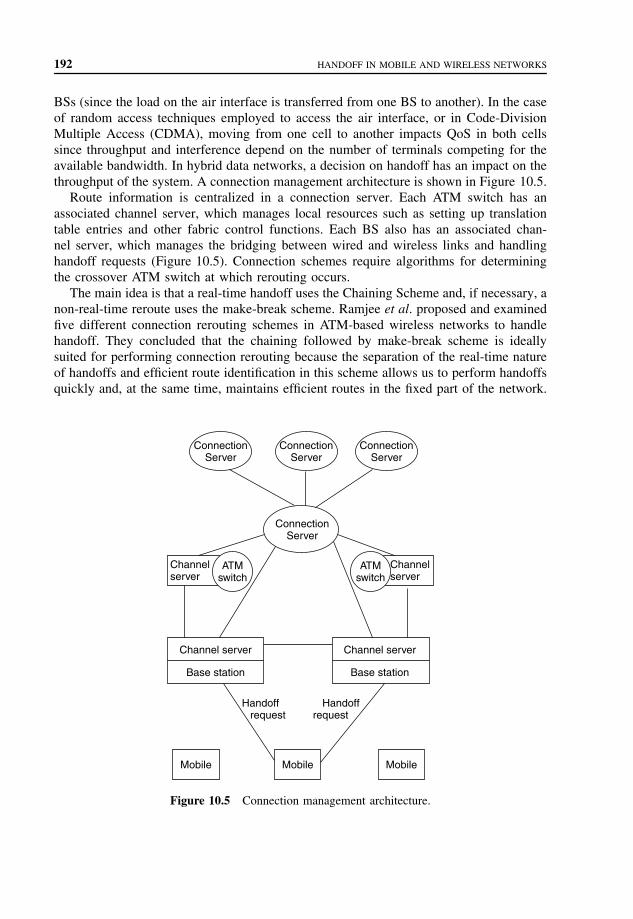
192 HANDOFF IN MOBILE AND WIRELESS NETWORKS
BSs (since the load on the air interface is transferred from one BS to another). In the caseof random access techniques employed to access the air interface, or in Code-DivisionMultiple Access (CDMA), moving from one cell to another impacts QoS in both cellssince throughput and interference depend on the number of terminals competing for theavailable bandwidth. In hybrid data networks, a decision on handoff has an impact on thethroughput of the system. A connection management architecture is shown in Figure 10.5.
Route information is centralized in a connection server. Each ATM switch has anassociated channel server, which manages local resources such as setting up translationtable entries and other fabric control functions. Each BS also has an associated chan-nel server, which manages the bridging between wired and wireless links and handlinghandoff requests (Figure 10.5). Connection schemes require algorithms for determiningthe crossover ATM switch at which rerouting occurs.
The main idea is that a real-time handoff uses the Chaining Scheme and, if necessary, anon-real-time reroute uses the make-break scheme. Ramjee et al. proposed and examinedfive different connection rerouting schemes in ATM-based wireless networks to handlehandoff. They concluded that the chaining followed by make-break scheme is ideallysuited for performing connection rerouting because the separation of the real-time natureof handoffs and efficient route identification in this scheme allows us to perform handoffsquickly and, at the same time, maintains efficient routes in the fixed part of the network.
ConnectionServer
ConnectionServer
ConnectionServer
ConnectionServer
Channelserver
Channelserver
ATMswitch
ATMswitch
Channel server
Base station
Channel server
Base station
Handoff request
Handoffrequest
Mobile Mobile Mobile
Figure 10.5 Connection management architecture.

ANALYSIS OF CHAINING HANDOFF APPROACHES 193
Handoff scheme chaining followed by make-break involves the following steps:
1. The mobile host sends a handoff request message to the new BS, identifying the oldBS and its connection server.
2. The new BS adds local translation table entries for its internal routing.3. The new BS asks the old BS to forward packets pertaining to the mobile host.4. The new BS sends back a handoff response message to the mobile host, instructing
the mobile host to transmit/receive through the new station. These four steps areaccomplished in real time (with a latency of 6.5 ms) to enable the mobile host toquickly switch over to the new wireless link. At this point, the chaining portion of thehandoff has been completed.
5. The new BS passes the updated route information to the connection server.6. The connection server performs necessary QoS computations on the new route. Note
that it has centralized knowledge of a significant portion of the route and can performthis calculation easily. If it detects a possible QoS guarantee violation, or if fixed linksare becoming congested and route efficiency is desired, it undertakes the followingsteps. In all other cases, the handoff flow terminates here.
7. This is the first step of the make-break portion of the handoff. The connection serveridentifies the best route to the COS, allocates resources along the new route, and setsup a new routing entry in the COS. The switch now multicasts cells received from thesource to both the BSs.
8. The connection server informs the new BS of the completion of route change, whichthen starts using the new route.
9. Finally, the connection server exchanges messages with the ATM switch, tearing downthe old routing entry. The connection server also requests the old and new BSs andswitches in the old route to deallocate the old resources.
10.9 ANALYSIS OF CHAINING HANDOFFAPPROACHES
Given a certain number of PVCs between neighborhoods and between BSs and ATMswitches, call blocks in the PVC can occur. A traffic jam in the chain can degradeperformance of the schemes.
If a traffic jam is unlikely, the HLS is not needed since it has more network traffic thanPVC-based scheme. In such cases, the PVC-based scheme is the best selection. But witha traffic jam (high number of calls in the area), the hop-limited handoff scheme is a goodselection. However, it does not consider the traffic balance in the BSs,, which belong tothe ATM switch.
In chaining followed by make-break handoff scheme, the route information is central-ized in a connection server. This helps to identify the COS immediately. The connectionserver simply determines the shortest path between the new BS and the old route, and thepoint of intersection is the COS. If this particular route is heavily loaded or is unable tomeet the QoS requirements for the connection, the connection server will attempt to find
194 HANDOFF IN MOBILE AND WIRELESS NETWORKS
other routes. The connection server then instructs the crossover ATM switch to reroutethe connection.
In chaining followed by a make-break handoff scheme, traffic jams in the chainingpart impact the performance of those schemes. The other route path, besides chaining, iscalculated through the Connection Server and is optimized. This scheme only considersthe traffic jams after the real-time stage during which the jams occur. Traffic jam in thechain parts should be prevented in real time.
10.10 SUMMARY
Handoff call management plays a major role in supporting acceptable levels of QoS.Connection rerouting involves limited handoff latency, maintaining an efficient route,limiting disruption of continuous media traffic, and limiting network switch update ratesdue to rerouting.
The approaches for connection rerouting are optimistic handoff, ordered handoff, pre-dictive handoff, and chaining handoff.
PROBLEMS TO CHAPTER 10
Handoff in mobile and wireless networks
Learning objectives
After completing this chapter, you are able to
• demonstrate an understanding of handoff in wireless networks;• explain different types of handoff;• explain predictive approaches to connection rerouting;• explain chaining followed by make-break handoff scheme.
Practice problems
10.1: How is handoff performed in wireless ATM networks?10.2: What happens if the current QoS is not supported when handoff occurs?10.3: What is the key idea of predictive approaches?10.4: What is the basic idea of chaining approaches?10.5: What is the goal of an optimistic handoff scheme?10.6: What is the goal of an ordered approach?10.7: What is the principle of predictive reservation policy (PRP)?10.8: Explain PVC-based scheme.10.9: Explain chaining followed by make-break handoff scheme.
Practice problem solutions
10.1: In WATM networks, end user devices are connected to switches via wired or wire-less channels. The switch is responsible for establishing connections with the fixed
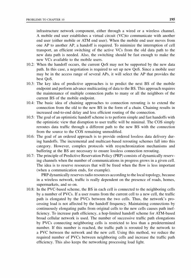
PROBLEMS TO CHAPTER 10 195
infrastructure network component, either through a wired or a wireless channel.A mobile end user establishes a virtual circuit (VC)to communicate with anotherend user (either mobile or ATM end user). When the mobile end user moves fromone AP to another AP, a handoff is required. To minimize the interruption of celltransport, an efficient switching of the active VCs from the old data path to thenew data path is needed. Also, the switching should be fast enough to make thenew VCs available to the mobile users.
10.2: When the handoff occurs, the current QoS may not be supported by the new datapath. In this case, a negotiation is required to set up new QoS. Since a mobile usermay be in the access range of several APs, it will select the AP that provides thebest QoS.
10.3: The key idea of predictive approaches is to predict the next BS of the mobileendpoint and perform advance multicasting of data to the BS. This approach requiresthe maintenance of multiple connection paths to many or all the neighbors of thecurrent BS of the mobile endpoint.
10.4: The basic idea of chaining approaches to connection rerouting is to extend theconnection from the old to the new BS in the form of a chain. Chaining results inincreased end-to-end delay and less efficient routing of the connection.
10.5: The goal of an optimistic handoff scheme is to perform simple and fast handoffs withthe optimistic view that disruption to user traffic will be minimal. The COS simplyreroutes data traffic through a different path to the new BS with the connectionfrom the source to the COS remaining unmodified.
10.6: The goal of an ordered approach is to provide ordered lossless data delivery dur-ing handoffs. The incremental and multicast-based rerouting schemes fall into thiscategory. However, complex protocols with resynchronization mechanisms andbuffering at the BS are necessary to ensure lossless connection rerouting.
10.7: The principle of Predictive Reservation Policy (PRP) consists of dynamically reserv-ing channels when the number of communications in progress grows in a given cell.The idea is to reserve resources that will be freed when the flow is less important(when a communication ends, for example).
PRP dynamically reserves radio resources according to the local topology, becausein a wireless network, traffic is really dependent on the presence of roads, homes,supermarkets, and so on.
10.8: In the PVC-based scheme, the BS in each cell is connected to the neighboring cellsby a number of PVCs. If a user roams from the current cell to a new cell, the trafficpath is elongated by the PVCs between the two cells. Thus, the network’s pro-cessing load is not affected by the handoff frequency. Maintaining connections bycontinuously elongating paths from original cells to the new cells causes path inef-ficiency. To increase path efficiency, a hop-limited handoff scheme for ATM-basedbroad cellular network is used. The number of successive traffic path elongationsby PVCs connecting neighboring cells is restricted to less than a predeterminednumber. If this number is reached, the traffic path is rerouted by the network toa PVC between the network and the new cell. Using this method, we reduce therequired number of PVCs between neighboring cells and increase the traffic pathefficiency. This also keeps the networking processing load light.

196 HANDOFF IN MOBILE AND WIRELESS NETWORKS
10.9: In chaining followed by make-break handoff scheme, the route information is cen-tralized in a connection server. This helps to identify the COS immediately. Theconnection server simply determines the shortest path between the new BS and theold route, and the point of intersection is the COS. If this particular route is heavilyloaded or is unable to meet the QoS requirements for the connection, the connectionserver will attempt to find other routes. The connection server then instructs thecrossover ATM switch to reroute the connection.

11
Signaling traffic in wirelessATM networks
Handoff algorithms in terrestrial wireless networks focus on the connection reroutingproblem. Basically, there are three connection rerouting approaches: full connection estab-lishment, partial connection reestablishment, and multicast connection reestablishment.Full connection establishment algorithms calculate a new optimum route for the call asfor a new call request. The resulting route is always optimal; however, the call rerout-ing delay and the signaling overheads are high. To alleviate these problems, a partialconnection reestablishment algorithm reestablishes certain parts of the connection routewhile preserving the remaining route. This way the route update process involves onlylocal changes in the route and can be performed faster. However, the resulting route maynot be optimal. In the multicast connection reestablishment algorithm, a Virtual Con-nection Tree (VCT) is created during the initial call admission process. The root of thetree is a fixed switching node, while the leaves are the switching centers to serve theuser terminal in the future. By using the multicast connection reestablishment method,when a call moves to a cell with a new switching center, connection rerouting is doneimmediately owing to the already established routes. The disadvantage of this algorithmis that network resources can be underutilized as a result of resources allocated in theconnection tree.
We define the Chain Routing Algorithm and implement it as a partial connectionreestablishment in the handoff scheme. This process is done during chain elongation.This handoff scheme can be used in the Wireless ATM (WATM) model.
11.1 A MODEL OF WATM NETWORK
A graph G(V, E) represents the topology of a WATM network. Graph G consists of twosets: a finite set V of vertices and a finite set E of edges. Graph G is represented by two
Mobile Telecommunications Protocols For Data Networks. Anna HacCopyright 2003 John Wiley & Sons, Ltd.
ISBN: 0-470-85056-6
198 SIGNALING TRAFFIC IN WIRELESS ATM NETWORKS
subgraphs: G1 that represents a set of ATM switching centers, and G2 that represents aset of Base Stations (BSs). The network model is defined as follows:
• The topology of the higher level of wired subnetwork is represented by an undirectedsubgraph G1 = (V1, E1), where each edge e ∈ E1 represents the number of commu-nication channels and each node in V1 represents an ATM switching center. G1 ⊂ G,V1 ⊂ V , and E1 ⊂ E.
• Each edge ei in G1 has a limited capacity to carry a number of calls; each of these callsoccupies one unit. The edges between ATM switching centers represent communicationchannels. The number of links is the same in each channel. The capacity of each edgeis defined as C1(ei).
• The subtopology of the BSs and their related ATM switching centers are represented byan undirected subgraph G2 = (V2, E2), where each edge e ∈ E2 represents the numberof channels between a base station and a switching center that are directly connected,and each node in V2 represents a base station connected to the ATM switching center.G2 ⊂ G, V2 ⊂ V , and E2 ⊂ E.
• Each edge ei in G2 has a limited capacity to carry a number of calls; each of thesecalls occupies one unit. The edges between BSs and their ATM switching centers alsorepresent channels. The number of links in each channel is the same. The capacity ofeach edge is defined as C2(ei).
• Two different BSs can establish a channel connection by allocating one edge or asequence of edges, possibly across several ATM switching centers.
• A communication call request is denoted by ri = (s1, s2, d1, d2, h1, h2). This call requestconsists of six elements: s1 and s2 are the source ATM switching center and the sourceBS, respectively; d1 and d2 are the destination switching center and the destinationBS, respectively; and h1 and h2 are the handoff switching center and the handoff BS,respectively.
• When a call request is a general call without handoff, the call request is denoted byri = (s1, s2, d1, d2) and the handoff request options are h1 = 0, and h2 = 0. When acall request is a handoff request, the handoff request options are h1 �= 0 and h2 �= 0.
• For each edge ei , which is between the ATM switching center and the BS, the totalnumber of channels allocated for a set of call requests R2(r1, r2, . . . , rn) that arrived inthe BS cannot exceed the capacity of the edge between the ATM switching center andthe BS. That is, �R2(ri) ≤ C2(ei) for all i, 1 ≤ i ≤ number of links in a base station.
• For each edge ei , which is among switching centers, the total number of channelsallocated for a set of call requests R1(r1, r2, . . . , rn) that arrived in the switching centerfrom the BS cannot exceed the capacity of the edge between ATM switching centers.That is, �R1(ri) ≤= C1(ei) for all i, 1 ≤ i ≤ number of links between a switchingcenter and its BSs.
• Let Idle r1(ei) denote the available number of channels ei among switching centers andIdle r2(ei) denote the available number of channels ei between switching centers andits BSs. A call request ri = (s1, s2, d1, d2) will be rejected if (Idle r1(ei) < R1(ri)) ∪(Idle r2(ei) < R2(ri)).
• Any mobile host can access the network directly via a radio link to a base station thatis virtually connected.

CHAIN ROUTING ALGORITHM 199
11.2 CHAIN ROUTING ALGORITHM
Handoff procedures involve a set of protocols to notify all the related entities of a par-ticular connection for which a handoff has been executed, and the connection has to beredefined. During the process, conventional signaling and additional signaling for mobil-ity requirements are needed. The mobile user is usually registered with a particular pointof attachment. In the voice networks, an idle mobile user selects a base station that isserving the cell in which it is located. This is for the purpose of routing incoming datapackets or voice calls. When the mobile user moves and executes a handoff from onepoint of attachment to another, the old serving point of attachment has to be informedabout the change. This is called dissociation. The mobile user will also have to reassociateitself with the new point of access to the fixed network. Other network entities involverouting data packets to the mobile user and switching voice calls that have to be awareof the handoff in order to seamlessly continue the ongoing connection or call. Dependingon whether a new connection is created before breaking the old connection, handoffs areclassified into hard and seamless handoffs.
The Chaining scheme extends the connection route from the previous BS to the newBS by provisioning some bandwidth using Virtual Channel (VC) or Virtual Path (VP)reservations between neighboring BSs. Chaining can simplify the protocols and reducesignaling traffic significantly and it can be accomplished quickly. However, chaining willtypically degrade the end-to-end performance of the connection and the connection routeis no longer the most efficient. This could lead to dropped calls if resources in the WATMare not available for chaining. To improve the route efficiently and reduce the number ofdropped calls, we propose the Chain Routing Algorithm.
We consider a broadband cellular network based on a hierarchical ATM network.In the planar environment, each cell is hexagonal, as shown in Figure 11.1. The BS
of each cell has some Permanent Virtual Circuits (PVCs) connected to the other BSs inneighboring cells. Also, each BS has a number of PVCs connected to the ATM switch
A B C D
ATM switch
1
2
3
4
Figure 11.1 Planar personal communication network.

200 SIGNALING TRAFFIC IN WIRELESS ATM NETWORKS
only for the use of handoff calls. A parameter describing Occupancy Rate of the PVC(ORP) is proposed for each BS. Overall, ORP is the larger number of occupancy rate ofPVCs between the BS and its neighboring BS and the occupancy rate of PVCs betweenthe BS and the ATM switch.
When a mobile makes a new call, its BS will establish a Switched Virtual Circuit(SVC) to carry the new call. When the terminal user moves to an adjacent cell, the trafficpath will be extended by a PVC from the current cell to the adjacent cell. The chainlength will be elongated by 1. Whenever the chain is elongated, one bit will be sent backto check the ORP of all the BSs on the chain route.
When the elongation is set up and all the BSs on this route have low occupancy rate,the network will follow the PVC-based scheme. In this scheme, if a user roams from itscurrent cell to a new cell, the traffic path is elongated by the PVCs between these twocells. The traffic path will keep growing if the user keeps roaming. However, maintainingconnections by continuously elongating paths from original cells to the new cells willcause the path to be inefficient.
When some parts of the route have a high occupancy rate, we propose two ways toreroute the chain parts of the route:
From the last station on the chain after each elongation, we propose sending one bitback through the chain and checking the ORP of each BS on the chain.
The path will be rerouted according to one of the following two schemes:
1. Select a route in which the length of the path is the shortest. If length of the route isshorter, it is more likely to be selected.
2. Select the path in which the PVCs have lower occupancy rate. That is, a PVC betweenan ATM switch and any BS in the elongation route can be set up in order to obtaina low ORP. The number of options that are available is N , where N is equal to thelength of the chain.
The chain has to be rerouted whenever there is a better chain route, and the speed ofelongation will be slowed down. The network efficiency can be improved significantly.
The path can be rerouted following the first scheme.From the last station on the chain after each elongation, we send one bit back through
the chain and check the ORP of each BS on the chain. If the resultant ORP of a basestation is close to jam, we stop, move back one BS, and use this BS’s PVC to connect tothe ATM switch. If the BS at the end of the chain has a very high ORP or it is jammed,we have to send a signal to the connection server to reroute the call.
If the speed of elongation is high, the signaling and calculation cost is reduced, andthe network efficiency is lower than in the Chain Routing.
We illustrate how the Chain Routing Algorithm operates by using an example. Referringto Figure 11.1, let the BS in Cell 1 be denoted as BS1. When a mobile initiates a new callin Cell 1, BS1 will establish an SVC between itself and the ATM switch. We considerthat the mobile roams to its neighboring Cell 2 and the traffic path is elongated by thePVCs between these two cells. One bit is sent back through the chain and we check theORP of each BS on the chain. Suppose both the BSs have low ORPs, then no reroutingoccurs. We consider that the mobile roams to its neighboring Cell 3 and the traffic path

CHAIN ROUTING ALGORITHM 201
is elongated by the PVCs between these two cells. One bit is sent back through the chainand the ORP of each BS on the chain is checked. Suppose both the BSs have low ORPs,then no rerouting occurs. Consider that the mobile roams to its neighboring Cell 4 andthe traffic path is elongated by the PVCs between these two cells. One bit is sent backthrough the chain and the ORP of each BS on the chain is checked.
We have four route options:
1. Cell 4 – Link D – ATM switch2. Cell 4 – Cell 3 – Link C – ATM switch3. Cell 4 – Cell 3 – Cell 2 – Link B – ATM switch4. Cell 4 – Cell 3 – Cell 2 – Cell 1 – Link A – ATM switch.
Suppose the BS of Cell 3 has a high ORP, then a new route 1 will be set up.If part of the chain route is within one ATM switch, this chain route can be easily
implemented. If the chaining route is across more than one ATM switch, this chain routemethod cannot be applied to the other ATM switches, because more than one ATMswitch is involved, and the reroute cannot be done locally. A signal has to be sent to theconnection server to reroute the call.
We illustrate how to solve this problem by using Figure 11.2.We make a PVC neighbor link between BSs within one ATM switch and a different
neighbor link connecting two BSs from two ATM switches. The neighbor link connectingtwo BSs from two ATM switches is a Cross ATM Switch Link (CASL). The CASL inFigure 11.2 is the link between Cell 3 and Cell 4.
The chain route has information about where it crossed more than one ATM switch.The Chain Routing Algorithm applies to the ATM area in which the chain started. When
A
12
3
4
5
6
B C
ATM switch ATM switch
Figure 11.2 Move with more than one ATM switch involved.

202 SIGNALING TRAFFIC IN WIRELESS ATM NETWORKS
the sent-back bit detects that it has arrived at the ATM switch in which the chain started,it will begin applying the Chain Routing Algorithm.
Suppose the mobile roams into Cell 6 and one bit is sent back through the chain route.When the sent-back bit sees the CASL, the Chain Routing Algorithm will be used.
In this case, we have three route options:
1. Cell 6 – Cell 5 – Cell 4 – Cell 3 – Link C – ATM switch.2. Cell 6 – Cell 5 – Cell 4 – Cell 3 – Cell 2 – Link B – ATM switch3. Cell 6 – Cell 5 – Cell 4 – Cell 3 – Cell 2 – Cell 1 – Link A – ATM switch.
If the BS of Cell 2 has a high ORP, for example, a new route 1 will be set up.
11.3 IMPLEMENTATION OF THE HANDOFF SCHEME
The Chain Routing Algorithm has to be implemented in the handoff scheme. The ChainRouting Algorithm is added to the handoff scheme (chaining followed by make-break) inStep 5 as follows:
1. The mobile host sends a handoff request message to the new BS identifying the oldBS and its connection server.
2. The new BS adds local translation table entries for its internal routing.3. The new BS asks the old BS to forward packets pertaining to the mobile host.4. The new BS sends back a handoff response message to the mobile host, instructing
the mobile host to transmit/receive through the new station.5. We include the Chain Routing Algorithm. A single bit is transferred from the mobile
host back to the starting point of the chain route. It checks the ORP of each BS.After the new route is found and the new BS chosen, which is connected to the ATMswitch, the new BS sends a message to the ATM switch channel server (performingmake, break, and break-make). The new BS can change its translation table entriesin its BS channel server immediately and the new connection between the chainto the ATM switch is established. This way, the chaining portion of the handoff iscompleted. Note that these five steps 1, 2, 3, 4, and 5 are accomplished in real time.
6. The new BS passes the updated route information to the connection server.7. The connection server performs necessary Quality-of-Service (QoS) computations on
the new route. Note that the connection server has centralized knowledge of a signif-icant portion of the route and can perform this calculation easily. If the connectionserver detects a possible QoS guarantee violation, or if the fixed links are becom-ing congested and route efficiency is desired, the connection server undertakes thefollowing steps: 8, 9, and 10.In all other cases, the handoff flow terminates at this point.
8. This is the first step of the make-break portion of the handoff. The connection serveridentifies the best route to the Crossover Switch (COS), allocates resources along thenew route, and sets up a new routing entry in the COS. The switch multicasts cellsreceived from the source to both BSs.

ANALYSIS OF THE CHAIN ROUTING ALGORITHM 203
9. The connection server informs the new BS of the completion of the route change,which then starts using the new route.
10. The connection server exchanges messages with the ATM switch, removing the oldrouting entry. The connection server also requests the old and new BSs and switchesin the old route to release the old resources.
11.4 ANALYSIS OF THE CHAIN ROUTINGALGORITHM
Upon receiving a handoff request from the mobile host, the new BS first executes theprocedures for the Chain Routing Algorithm scheme. The new BS then transmits thehandoff response message to the mobile host so that the mobile host starts listening andtransmitting via the new BS. The new BS then initiates the make-break rerouting proce-dure. The scheme combines the advantages of both make-break and Chaining schemes. Itresults in fast handoffs so that the mobile host is quickly connected to the new BS duringhandoff. Furthermore, an optimistic scheme can be later employed, as needed, in order tomake more effective use of bandwidth and to minimize disruption. This scheme is usefulin cases when a user is handed over in a network that is lightly loaded or when the mobileuser does not travel far during a connection. In such cases, the handoff performed usingchaining does not disrupt the communication, and since the network is lightly loaded,there will be no noticeable performance degradation due to the increased hop count. Ifthe network becomes congested or if the user moves far enough so that the effects ofthe extended chain are undesirable, the make-break scheme can be applied to reroutethe connection.
11.4.1 Comparison of chain routing algorithm with Hop-limited method
The elongation pattern in the Chain Routing Algorithm is one adjustment of the Hop-limited handoff scheme and it is based on the Chaining scheme. By analyzing the Chainingscheme and the Hop-limited handoff scheme, we compare the results with Chain Rout-ing Algorithm scheme. Akyildiz et al. present performance analysis of the Hop-limitedhandoff scheme and Chaining scheme. We make the following assumptions.
1. The call holding time TM is exponentially distributed with mean 1/µM .2. The originating calls arrive in a cell following a Poisson process with rate λo.3. The time interval R during which a mobile resides in a cell called the cell sojourn
time has a general distribution. The cell sojourn times, R(1), R(2), . . . , are independentand identically distributed.
We consider a mobile in a cell. A Virtual Circuit (VC) connecting the cell’s BS to theATM switch or to an adjacent cell’s BS is occupied by the mobile. The VC can be releasedin three cases: (i) the connection is naturally terminated; (ii) the connection is forced tobe terminated due to handoff blocking; and (iii) the mobile has already successivelymade r − 1 handoffs since it came to the current cell and it is making the rth handoff

204 SIGNALING TRAFFIC IN WIRELESS ATM NETWORKS
attempt (here r is a system parameter). Let the time interval from the moment the VC isoccupied by the call to the moment the VC is released be Tr and we will derive the VC’sholding time.
First we only consider cases (ii) and (iii). Let Pf be the probability that the call isblocked due to unavailability of the PVC when the mobile tries to handoff to anothercell. Let θr be the VC’s holding time under this consideration and n be the number ofhandoffs the mobile will try from the moment it comes to the cell to the moment the VCis released. For 1 ≤ i < r , p(n = i) = pf (1 − pf )i−1; p(n = r) = (1 − pf )r−1.
Let N [z] be the generating function of variable n, and θ∗r (s) be the Laplace–Stieltjes
Transform (LST) of θr . We have θ∗r (s) = N [R∗(s)], where R∗(s) is the LST of the
distribution function of R. The distribution of Tr is FT r(t) = Pr(min(θr , T M) ≤ t). Forthe assumption that R is also exponentially distributed with mean µR , the mean of Tr isE[Tr] = {1 − [µr (1 − Pf )/(µM + µR)]r}/(µM + Pf µR).
Let us derive the handoff call arrival rate. There are two kinds of handoff calls. Thefirst type of handoff call will request a PVC connecting the BS to the ATM switch, withmean arrival rate λh1; the handoff call of another type will request a PVC connected toits previous cell’s BS, with mean arrival rate λh2. Let pi be the probability that a callwill make the ith handoff request. Then we have pi = (1 − pf )i−1[µR/(µM + µR)]i .
Assume the probabilities of a handoff call coming from arbitrary neighboring cells arethe same. Let N1 be the mean number of SVCs connecting a cell to the ATM switch. Wehave N1 = λo(1 − pn)E[Tr ].
Let N2 be the number of required PVCs connecting each BS to the ATM switch forrerouting requests. We can model this as an M/M/m/m queuing system, where the arrivalrate is λh1 and the average holding time is E[Tr]. Thus, we have
Pf = [((λh1E[Tr])N2/N2!)]N2∑n=2
(λh1E[Tr])n/n!
Let N3 be the required PVCs to connect the BS to a neighboring BS. This exampleis more complex, and we calculate the upper bound. Assume the mean holding time ofall PVCs is E[Tr−1], then we can model this case as an M/M/m/m system, with sixneighboring cells, the arrival rate is λh2/6 and mean holding time E[Tr−1]. We have
Pf = ((λh2E[Tr−1]/6)N3/N3!)N3∑n=0
(λh2E[Tr−1]/6)n/n!
Using this equation we can obtain N3 to satisfy the Pf requirement.Now we roughly compare the Hop-Limiting Scheme (HLS) with the VCT and Chaining
scheme. Assume there are 49 cells. Table 11.1 shows the required number of VCs fordifferent schemes, given the new call arrival rate is 11.9 calls per minute, the mean callholding time is 2 min. and the mean call sojourn time is also 2 min. The new call blockingprobability is 0.01 and handoff call blocking probability is 0.001. The row r = ∞ shows

ANALYSIS OF THE CHAIN ROUTING ALGORITHM 205
Table 11.1 Required number of VCs for differentschemes
N1 N2 N3 Total
r = 1 11.78 24 0 35.78r = 3 20.6 10 54 84.6r = 5 22.8 5 66 93.8r = ∞ 23.56 0 72 97.56VCT 1155 0 0 1155
the requirements of the Chaining scheme. When r is finite, the number of required VCsis lower than those of the Chaining and VCT schemes. This means that the bandwidthefficiency is higher. When r = 1, the number of required VCs is the smallest, but duringeach handoff a network is evoked to reroute the traffic path, which means that the networkprocessing load is the heaviest. When choosing a value for r , there is a trade-off betweenthe number of required VCs and the ATM switch processing load.
Comparing the Hop-limited handoff scheme with relatively big r values, the ChainRouting Algorithm tends to use higher number of required PVCs (N2) connecting eachBS to the ATM switch for rerouting requests. When the occupancy rate of the route pathincreases, the Chain Routing Algorithm needs to revoke more rerouting at the chain partof the route. At the same time, the Chain Routing Algorithm tends to use lower numberof PVCs (N3) to connect the BS to the neighboring BS compared with the Hop-limitedhandoff scheme with relatively small r values. Because the Chain Routing Algorithmneeds to revoke more rerouting at the chain part of the route, generally the length of theroute is smaller than in the Hop-limited handoff scheme with relatively small r values.
Chain Routing Algorithm produces less signaling traffic and network processing loadthan the Hop-limited handoff scheme with a small number of r , because it will not evokethe network to reroute the traffic path so often. At the same time, it has lower bandwidthefficiency than the Hop-limited handoff scheme with small number of r , because it willneed more VCs to connect the BS to a neighboring BS.
Chain Routing Algorithm produces more signaling traffic and network processing loadthan the Hop-limited handoff scheme with a large number of r , because it needs to do arerouting process in the chaining parts and it evokes the network to reroute the traffic pathmore often. At the same time, it has higher bandwidth efficiency than the Hop-limitedhandoff scheme with large number of r , because it will need less VCs to connect the BSto a neighboring BS.
The Chain Routing Algorithm is another option that can be selected besides the Hop-limited handoff scheme. It can give better performance than the Hop-limited handoffscheme in certain cases. Its performance can be adjusted by tuning the threshold at whichit performs the chain routing calculation.
11.4.2 Analysis of the signaling traffic cost
Signaling traffic is caused by reroute-related updates and modifications occurring in theATM switches. In the Chaining scheme we can provision bandwidth between neighboring

206 SIGNALING TRAFFIC IN WIRELESS ATM NETWORKS
BSs and thereby avoid modifying the switch routing entries. Thus, there is a clear trade-off between the amount of bandwidth provisioned and the number of reroute updates.The amount of provisioned bandwidth can be used as a tunable parameter for engineeringnetwork resources.
We analyze the signaling traffic cost in the Chain Routing Algorithm scheme. Whenno reroute is found, the starting BS has a bit that remembers this BS is the starting pointof the chain. The signal needs to be transferred in a single bit that is transferred fromthe mobile host back to the starting point of the chain when the mobile host performsa handoff.
When rerouting is needed, one message is sent to the ATM switch channel serverand one message is sent to the BS server. The messages to the ATM switch channelserver contain the necessary 3-tuple [Virtual Path Identifier (VPI), Virtual Channel Iden-tifier (VCI), and port] for modifying the switch translation table entry. The messages tothe BS channel server (add entry, delete entry, delete forwarding entry, and forward) alsocontain only the necessary 3-tuples for the BS to update its translation table entries.
Because QoS computation is not involved, the Chain Routing Algorithm scheme canbe performed in real time. It reduces the risk of a lost connection because of limitationof bandwidth availability and it improves the efficiency of the PVC between neighboringBSs and between the BS and the ATM switches. A possible QoS guarantee violation orcongested fixed links are reduced because previous routes before handoff are optimizedthrough connection server. The most likely problem is the handoff part. If the chain partis improved, the entire route is improved. As a result, the chance of going through Steps 8and 9 and the signaling traffic involved in 8 and 9 is reduced.
Signaling traffic depends on the network configuration and protocols involved. In thesimulation model, when a mobile user roams within the ATM switch area, the signalingtraffic is low in the Chain Routing Algorithm scheme. It performs like the Chain RoutingAlgorithm scheme. When a rerouting process is required, the signaling messages are afew bytes long because only one ATM switch is involved. The longest message is thehandoff request message from the mobile user. This message is 44 bytes long and includesthe mobile identity, old BS channel server identifier, and the 3-tuple (VPI, VCI, and port)of the translation table entry at the same ATM switch. The route update message to theconnection server contains the identity of the mobile endpoint and the two BSs involvedin the Chaining scheme.
When the mobile user roams outside the original ATM switch and a reroute is requestedbecause of the overload of links or QoS problem, the new BS needs to identify the bestroute to the COS, allocate resources along the route, and then exchange messages withthe COS, which executes break-make or make-break operations. In this case, the ChainRouting Algorithm performs better than the Chaining scheme.
1. In certain cases, because of the Chain Routing Algorithm, the links connecting BSsand the links connecting the ATM switch and the BS are utilized more efficiently, sothis kind of reroute does not occur as often as in the Chaining scheme.
2. In certain cases, when the mobile user roams to the other ATM switch area, the chainpart inside the original ATM switch area will be rerouted according to the ChainRouting Algorithm, so this portion of the routing path will probably not have overload
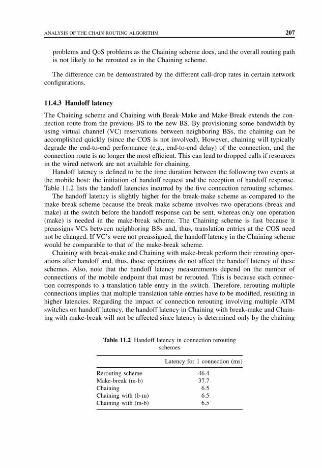
ANALYSIS OF THE CHAIN ROUTING ALGORITHM 207
problems and QoS problems as the Chaining scheme does, and the overall routing pathis not likely to be rerouted as in the Chaining scheme.
The difference can be demonstrated by the different call-drop rates in certain networkconfigurations.
11.4.3 Handoff latency
The Chaining scheme and Chaining with Break-Make and Make-Break extends the con-nection route from the previous BS to the new BS. By provisioning some bandwidth byusing virtual channel (VC) reservations between neighboring BSs, the chaining can beaccomplished quickly (since the COS is not involved). However, chaining will typicallydegrade the end-to-end performance (e.g., end-to-end delay) of the connection, and theconnection route is no longer the most efficient. This can lead to dropped calls if resourcesin the wired network are not available for chaining.
Handoff latency is defined to be the time duration between the following two events atthe mobile host: the initiation of handoff request and the reception of handoff response.Table 11.2 lists the handoff latencies incurred by the five connection rerouting schemes.
The handoff latency is slightly higher for the break-make scheme as compared to themake-break scheme because the break-make scheme involves two operations (break andmake) at the switch before the handoff response can be sent, whereas only one operation(make) is needed in the make-break scheme. The Chaining scheme is fast because itpreassigns VCs between neighboring BSs and, thus, translation entries at the COS neednot be changed. If VC’s were not preassigned, the handoff latency in the Chaining schemewould be comparable to that of the make-break scheme.
Chaining with break-make and Chaining with make-break perform their rerouting oper-ations after handoff and, thus, those operations do not affect the handoff latency of theseschemes. Also, note that the handoff latency measurements depend on the number ofconnections of the mobile endpoint that must be rerouted. This is because each connec-tion corresponds to a translation table entry in the switch. Therefore, rerouting multipleconnections implies that multiple translation table entries have to be modified, resulting inhigher latencies. Regarding the impact of connection rerouting involving multiple ATMswitches on handoff latency, the handoff latency in Chaining with break-make and Chain-ing with make-break will not be affected since latency is determined only by the chaining
Table 11.2 Handoff latency in connection reroutingschemes
Latency for 1 connection (ms)
Rerouting scheme 46.4Make-break (m-b) 37.7Chaining 6.5Chaining with (b-m) 6.5Chaining with (m-b) 6.5

208 SIGNALING TRAFFIC IN WIRELESS ATM NETWORKS
of the neighboring BSs. On the other hand, in break-make and make-break schemes,handoff latency is directly proportional to the number of ATM switches that need to beupdated along the new route. Thus, the separation of connection rerouting from the real-time phase in Chaining with break-make and Chaining with make-break schemes, resultsin low handoff latency regardless of the number of switches involved in the reroutingoperations. In the Chain Routing Algorithm scheme, the Chain Routing Algorithm onlyapplies to the chain part of the route path, translation entries at the COS need not bechanged. The time cost of chain routing attributed to handoff latency will be comparableto the Chaining Algorithm.
In certain cases, some calls are blocked because of the overload of the chain part of theroute path and those links between the ATM switch and the BSs. In cases in which thosecalls have been rerouted, the handoff latency is comparable to the make-break scheme orthe break-make scheme. For the HLS and Chain Routing Algorithm scheme, the routeshave to be rerouted in certain circumstances.
For HLS, when a mobile has successfully made r − 1 handoffs, and its rth handoffrequest is also successful, its traffic path would be rerouted from the new BS to theATM switch to which it belongs. Regardless of whether the mobile user roams out of thecurrent ATM switch area to a new ATM switch or not, the connection server performsmake-break or break-make and necessary QoS computations on the new route. If themobile user roams out of the current ATM switch area, the handoff latency is directlyproportional to the number of ATM switches that need to be updated along the new route.
The handoff latency is similar to a make-break or break-make scheme. For the ChainRouting Algorithm scheme, the route will be rerouted when the occupancy of the VCsbetween the current BS and its neighboring BS or of the VCs between an ATM switchand the base station reach a certain value. Two cases are considered: one when the userroams inside an ATM switch area and the other when the user roams outside the currentATM switch area and the handoff latency is different from HLS. Regardless of whetherthe user roams inside an ATM switch area or the user roams outside the current ATMswitch area, only the chain part of the route path inside the original ATM switch areawill be rerouted. The handoff latency is similar to the Chaining scheme. Because handofflatency of the Chain Routing Algorithm consists of rerouting cost and chaining cost andhandoff latency of the Chaining scheme consists of chaining cost only, the latency ofthe Chain Routing Algorithm is higher than that of the Chaining scheme. Depending onthe r value of HLS, the latency of Chain Routing Algorithm is higher than that of theHLS with a large r value but less than that of an HLS with a small r value. Supposethose routes that are blocked need to be rerouted as those in break-make and make-breakschemes. The average handoff latency of different schemes can be estimated as follows:
1. Chaining latency (during elongation, estimated to 6.5 ms).2. Chain Routing Algorithm scheme latency (during elongation, estimated to 6.5 ms).3. Rerouting cost (rerouting inside one ATM switch, estimated to 6.5 ms).4. Rerouting cost (rerouting outside one ATM switch, estimated to 45 ms).
Regarding the impact of connection rerouting involving multiple ATM switches onhandoff latency, the handoff latency in Chaining with make-break will not be affected

ANALYSIS OF THE CHAIN ROUTING ALGORITHM 209
since latency is determined only by the chaining of the neighboring BSs. Thus, the separa-tion of connection rerouting from the real-time phase in Chaining with make-break resultsin a low handoff latency regardless of the number of switches involved in the reroutingoperation. While connection rerouting due to handoffs is similar to rerouting due to thefailure of network components, there are two important differences. First, handoffs aremuch more frequent than network faults. With frequent reroutes, the disruption caused toongoing connections has to be minimized. On the other hand, in many cases applicationswill be willing to tolerate some disruption due to rare network fault rerouting scenar-ios. Second, handoffs result in connection reroutes that are limited to a small geographiclocality (e.g., neighboring BSs). On the other hand, reroutes due to failures may involvereestablishing the entire connection.
In ATM networks, all data is transmitted in small, fixed-size packets. Owing to thehigh-speed transfer rate (in the range of hundreds to thousands of Mb s−1) and rather shortcell length (53 bytes), the ratio of propagation delay to cell transmission time and the ratioof processing time to cell transmission time of ATM networks will increase significantlymore than that in the existing networks. This leads to a shift in the network’s performancebottleneck from channel transmission speed (in most existing networks) to the propagationdelay of the channel and the processing speed at the network switching nodes. This chainrouting method will decrease the workload in the network switching nodes.
1. There is no need to identify the COS when rerouting, because chain routing methodworks only with one ATM switch.
2. There is no need to calculate the best route through the connection server because itis done locally to reduce signaling traffic.
3. It is easy to implement. Only one parameter ORP is added to the new scheme and thecalculation is very simple. It complies with existing ATM signaling standards and itsimplementation leaves commercially available ATM components unaffected.
4. It is in real time.5. It can significantly reduce signaling traffic.6. In the new handoff scheme, the concern of traffic jam is included. This scheme can
handle different kinds of situations efficiently. By doing this, the whole PVC in thisATM switch will have the highest utility efficiency, so that the system adopting thisscheme can handle many more handoffs.
The Code of the Chain Routing Algorithm is as follows:Each cell has the following parameters:
• ORP1 – overall occupancy rate of PVCs to ATM switch• ORP2 – overall occupancy rate of PVCs between neighbors (in one direction)• Chain length – Number of BSs on the chain after CASL.• ROU – new route needs to be implemented• CASL – Cross ATM Switch Link.
The ALGORITHM is as follows:
CASL=NULL;ROU=NULL;

210 SIGNALING TRAFFIC IN WIRELESS ATM NETWORKS
If mobile roams to a new BSIf the link = CASL
CASL !=NULLElse Chain length ++;Traffic path will be extended by a PVC from the current cell tothe adjacent cellWhile (CASL !=NULL) on the chain route
Go through the route until pass CASLFor (i=0, i<Chain Length, i++)Route [i]=From the end of the chain (from which BS the mobile hasjust arrived)go through i number of BSs and go to the ATM switch.For (j=0, j<i, j++)Check the ORPs of the BSs on Route[i]If (ORP1=jammed) or (ORP2=jammed)Determine from Route[0-j], which Route has the lowest ORP
Record the Route as ROUTerminate the loop.
End IFORP of Route[j]=highest ORP of those BSsIf ROU !=NULLReroute the chain route as ROU
11.5 SUMMARY
The handoff call management scheme reduces signaling traffic in the wireless ATM net-work and improves the efficiency of virtual channels. Chaining followed by make-breakalgorithm is a suitable handoff scheme for various situations. In the chaining part of thescheme, a chain routing algorithm is studied and compared with the HLS. The imple-mented algorithm improves the performance of the existing scheme in call-drop ratesso as to reduce the signaling traffic in the WATM network. This method complies withthe existing ATM signaling standard and its implementation leaves commercially ATMcomponents unaffected. It considers the traffic condition when chaining and it is easy toimplement in the chaining followed by the make-break scheme.
PROBLEMS TO CHAPTER 11
Signaling traffic in wireless ATM networks
Learning objectives
After completing this chapter, you are able to
• demonstrate an understanding of connection rerouting;• explain the role of a chaining scheme;• explain how signaling traffic occurs;• explain handoff latency;

PROBLEMS TO CHAPTER 11 211
Practice problems
11.1: What are the connection rerouting approaches?11.2: What are the schemes for path rerouting?11.3: How is chain routing implemented in the handoff scheme?11.4: What does the new base station (BS) do upon receiving a handoff request?11.5: What is the cause for the signaling traffic?11.6: What is handoff latency?
Practice problem solutions
11.1: There are three connection rerouting approaches: full connection establishment,partial connection reestablishment, and multicast connection reestablishment.
11.2: The path is rerouted according to the shortest path scheme, or the path in whichthe PVCs have lower occupancy rate is selected.
The chain has to be rerouted whenever there is a better chain route and thespeed of elongation will be slowed down. The network efficiency can be improvedsignificantly.
11.3: Implementing chain routing involves transferring of a single bit from the mobilehost back to the starting point of the chain route. It checks ORP of each BS. Afterthe new route is found and the new BS, which is connected to the ATM switch ischosen, the new BS sends a message to the ATM switch channel server (performingmake, break, and break-make). The new BS can change its translation table entriesin its channel server immediately and the new connection between the chain to theATM switch is established.
11.4: Upon receiving a handoff request from the mobile host, the new BS first executes theprocedures for the Chain Routing Algorithm scheme. The new BS then transmitsthe handoff response message to the mobile host so that the mobile host startslistening and transmitting via the new BS. The new BS then initiates the make-breakrerouting procedure.
11.5: Signaling traffic is caused by reroute-related updates and modifications occurringin the ATM switches.
11.6: Handoff latency is defined as the time duration between the following two eventsat the mobile host: the initiation of handoff request and the reception of hand-off response.


12
Two-phase combined QoS-basedhandoff scheme
Wireless Personal Communication Services (PCS) and broadband networking for deliver-ing multimedia information represent two well-established trends in telecommunications.While technologies for PCS and broadband communications have historically been devel-oped independently, harmonization into a single architectural framework is motivated byan emerging need to extend multimedia services to portable terminals. With the grow-ing acceptance of Asynchronous Transfer Mode (ATM) as the standard for broadbandnetworking, it has become appropriate to consider the feasibility of standard ATM ser-vices into next-generation microcellular wireless and PCS scenarios. The use of ATMprotocols in both fixed and wireless networks promises the important benefit of seam-less multimedia services with end-to-end Quality-of-Service (QoS) control. The wirelessATM (WATM) specification provides an option to existing ATM networks that wish tosupport terminal mobility and radio access while still retaining backward compatibilitywith ATM equipments.
The current developments on WATM are mainly based on ATM as the backbonenetwork with a wireless last-hop extension to the mobile host. Mobility functions areimplemented into the ATM switches and the Base Stations (BSs). WATM helps to bringmultimedia to mobile computers. Compared with the wireless LANs, which have a lim-itation of bandwidth to support multimedia traffic and slow handoff, the bandwidth ofexisting mobile phone systems is sufficient for data and voice, but it is still insufficient forreal-time multimedia traffic. ATM has more efficient networking technology for integratingservices, flexible bandwidth allocation, and service type selection for a range of applica-tions. The current interest and research efforts are intense enough to claim that WATMwill continue to be pursued as a research and development topic in the next few years.
There are two major components in WATM networks:
1. A radio access layer providing high-bandwidth wireless transmission with appropriateMedium Access Control (MAC), Data Link Control (DLC), and so on.
Mobile Telecommunications Protocols For Data Networks. Anna HacCopyright 2003 John Wiley & Sons, Ltd.
ISBN: 0-470-85056-6

214 TWO-PHASE COMBINED QoS-BASED HANDOFF SCHEME
2. A mobile ATM network for interconnection of BSs [Access Points (APs)] with appro-priate support of mobility related functions, such as handoff and location management.
We focus on the mobile ATM handoff control required to support Mobile Terminal(MT) migration from one WATM microcell BS to another. The handoff function shouldensure that the ongoing connection is rerouted to another AP in a seamless manner. Thedesign goal of the handoff in WATM is to prevent service disruption and degradationduring and after the handoff process.
To support wireless users in an ATM network, the main challenges are due to themobility of the wireless users. If a wireless user moves while communicating with anotheruser or a server in the network, the network may need to transfer the radio link of the userbetween radio APs in order to provide seamless connectivity to the user. The transfer ofa user’s radio link is referred to as handoff. During a handoff event, the user’s existingconnection may need to be rerouted in order to meet delay, QoS or cost criteria, orsimply to maintain connectivity between two users, or between a server and wirelessusers. Rerouting is critical to wireless networks that need to maintain connectivity to awireless user through multiple, geographically dispersed radio APs. Rerouting must bedone quickly to maintain connectivity to the network during a handoff event. In addition,the resulting routes must be optimum. A two-phase interswitch handoff scheme meets therequirement of the rerouting. In the first phase, connections are rapidly rerouted and inthe second phase a route optimization procedure is executed. For the two-phase handoffscheme, the first phase is simply implemented by path extension and the second phase isimplemented by partial path reestablishment.
We describe the QoS-based rerouting algorithm that is designed to implement two-phase interswitch handoff scheme for WATM networks. We use path extension for eachinterswitch handoff, and invoke path optimization when the handoff path exceeds thedelay constraint or maximum path extension hops constraint. We study three types ofpath optimization schemes: combined QoS-based, delay-based and hop-based path rerout-ing schemes.
We use QoS combined path optimization scheme for WATM network. We focus on theproblems related to the support of mobility in the WATM network. This scheme determineswhen to trigger path optimization for the two-phase handoff and how to minimize theservice disruption during path optimization.
12.1 WIRELESS ATM ARCHITECTURE
A WATM network is intended to support integrated broadband services to MTs through anATM User Network Interface (UNI). Figure 12.1 shows a network diagram that illustratesvarious network entities and the functions that are required to support mobility in suchan ATM network.
In this architecture, the MT is an ATM end system that can support multimedia appli-cations. The wireless link between the MT and BS provides the desired ATM transportservices to the MT. A mobility-enhanced signaling protocol based on the ITU recommen-dation Q.2931 is used by the MT, BS, and Mobility Support Switches (MSS) to supporthandoff-related functions.

WIRELESS ATM ARCHITECTURE 215
Wireless control
Wireless control
Wireless control
Mobilesupport
ATM switch
Mobilesupport
ATM switch
LS
PNNI (Q.2931 +)
LS
PVC
ATM UNI
ATM UNI
MT
MT
Q.2931 +
Q.2931 +
BS1
BS2
ATM switch
LS
LS
RegularATM switch
Switch host
Q.2931 +
Figure 12.1 Network entities and functions for mobility support in ATM network.
There are two types of interfaces in ATM: the UNI and Network-to-Network Interface(NNI). Both interfaces can be private or public depending on the network. In the locationmanagement scheme that is proposed as Location Server (LS), a database is required toregister the location of the MT.
The ATM Forum designed the WATM specifications, which are compatible with standardATM protocols by providing ATM-based radio access as well as extensions for mobility sup-port within an ATM network. The wireline and wireless ATM protocol stacks are shown inFigure 12.2, in which the shaded areas represent new sublayers added for wireless support.
At the bottom of the protocol stack is the physical layer. In order to support awide range of multimedia applications, the WATM physical layer should provide rea-sonably high data rates. A MAC protocol in WATM is needed to meet the followingrequirements:
• It should be able to work with the upper-layer protocol seamlessly.• The MAC layer should be designed to use bandwidth efficiently to accommodate a
reasonably large number of users.• The MAC protocol should guarantee a certain QoS to the user for various services,
such as Constant Bit Rate (CBR), Variable Bit Rate (VBR), Available Bit Rate (ABR),and Unspecified Bit Rate (UBR).
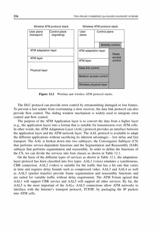
216 TWO-PHASE COMBINED QoS-BASED HANDOFF SCHEME
Wireline ATM protocol stack Wireless ATM protocol stack
User plane(transport)
Control plane(signaling)
ATM adaptation layer
ATM layer
Physical layer
Userplane
Control plane
ATM adaptation layer
ATM layer
Data link control
Medium access control
Wireless physical layer
Radioaccesscontrol
Mobility control
Figure 12.2 Wireline and wireless ATM protocol stacks.
The DLC protocol can provide error control by retransmitting damaged or lost frames.To prevent a fast sender from overrunning a slow receiver, the data link protocol can alsoprovide flow control. The sliding window mechanism is widely used to integrate errorcontrol and flow control.
The purpose of the ATM Application layer is to convert the data from a higher layer(e.g., the application layer) into a format that is suitable for transmission over ATM cells.In other words, the ATM Adaptation-Layer (AAL) protocol provides an interface betweenthe application layer and the ATM network layer. The AAL protocol is available to adaptthe different applications without sacrificing its inherent advantages – low delay and fasttransport. The AAL is broken down into two sublayers: the Convergence Sublayer (CS)that performs service-dependent functions and the Segmentation and Reassembly (SAR)sublayer that performs segmentation and reassembly. In order to define the functions ofthe CS, we can divide the services into four classes as shown in Table 12.1.
On the basis of the different types of services as shown in Table 12.1, the adaptation-layer protocol has been classified into five types. AAL1 (voice) emulates a synchronous,CBR connection. AAL2 (video) is suitable for the traffic that has a bit rate that variesin time and requires delay bounds such as compressed video. AAL3 and AAL4 as wellas AAL5 (packet transfer) provide frame segmentation and reassembly functions andare suited for variable traffic without delay requirement. The ATM Forum agreed thatAAL1 will support CBR service and AAL5 will support all other services. By far, theAAL5 is the most important of the AALs. AAL5 connections allow ATM networks tointerface with the Internet’s transport protocol, TCP/IP, by packaging the IP packetsinto ATM cells.
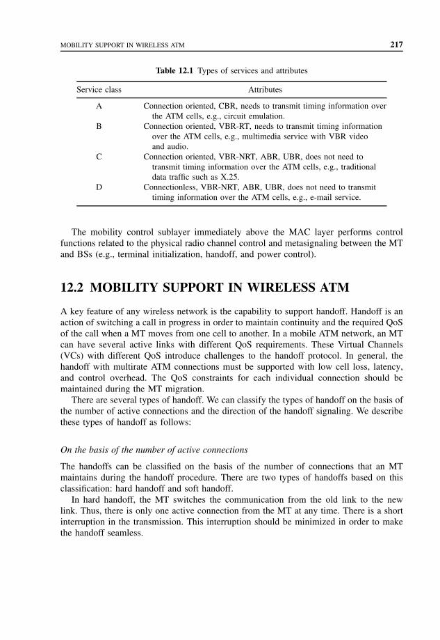
MOBILITY SUPPORT IN WIRELESS ATM 217
Table 12.1 Types of services and attributes
Service class Attributes
A Connection oriented, CBR, needs to transmit timing information overthe ATM cells, e.g., circuit emulation.
B Connection oriented, VBR-RT, needs to transmit timing informationover the ATM cells, e.g., multimedia service with VBR videoand audio.
C Connection oriented, VBR-NRT, ABR, UBR, does not need totransmit timing information over the ATM cells, e.g., traditionaldata traffic such as X.25.
D Connectionless, VBR-NRT, ABR, UBR, does not need to transmittiming information over the ATM cells, e.g., e-mail service.
The mobility control sublayer immediately above the MAC layer performs controlfunctions related to the physical radio channel control and metasignaling between the MTand BSs (e.g., terminal initialization, handoff, and power control).
12.2 MOBILITY SUPPORT IN WIRELESS ATM
A key feature of any wireless network is the capability to support handoff. Handoff is anaction of switching a call in progress in order to maintain continuity and the required QoSof the call when a MT moves from one cell to another. In a mobile ATM network, an MTcan have several active links with different QoS requirements. These Virtual Channels(VCs) with different QoS introduce challenges to the handoff protocol. In general, thehandoff with multirate ATM connections must be supported with low cell loss, latency,and control overhead. The QoS constraints for each individual connection should bemaintained during the MT migration.
There are several types of handoff. We can classify the types of handoff on the basis ofthe number of active connections and the direction of the handoff signaling. We describethese types of handoff as follows:
On the basis of the number of active connections
The handoffs can be classified on the basis of the number of connections that an MTmaintains during the handoff procedure. There are two types of handoffs based on thisclassification: hard handoff and soft handoff.
In hard handoff, the MT switches the communication from the old link to the newlink. Thus, there is only one active connection from the MT at any time. There is a shortinterruption in the transmission. This interruption should be minimized in order to makethe handoff seamless.
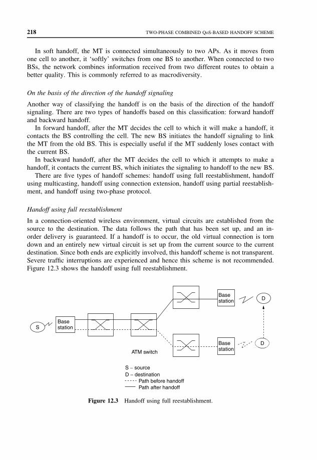
218 TWO-PHASE COMBINED QoS-BASED HANDOFF SCHEME
In soft handoff, the MT is connected simultaneously to two APs. As it moves fromone cell to another, it ‘softly’ switches from one BS to another. When connected to twoBSs, the network combines information received from two different routes to obtain abetter quality. This is commonly referred to as macrodiversity.
On the basis of the direction of the handoff signaling
Another way of classifying the handoff is on the basis of the direction of the handoffsignaling. There are two types of handoffs based on this classification: forward handoffand backward handoff.
In forward handoff, after the MT decides the cell to which it will make a handoff, itcontacts the BS controlling the cell. The new BS initiates the handoff signaling to linkthe MT from the old BS. This is especially useful if the MT suddenly loses contact withthe current BS.
In backward handoff, after the MT decides the cell to which it attempts to make ahandoff, it contacts the current BS, which initiates the signaling to handoff to the new BS.
There are five types of handoff schemes: handoff using full reestablishment, handoffusing multicasting, handoff using connection extension, handoff using partial reestablish-ment, and handoff using two-phase protocol.
Handoff using full reestablishment
In a connection-oriented wireless environment, virtual circuits are established from thesource to the destination. The data follows the path that has been set up, and an in-order delivery is guaranteed. If a handoff is to occur, the old virtual connection is torndown and an entirely new virtual circuit is set up from the current source to the currentdestination. Since both ends are explicitly involved, this handoff scheme is not transparent.Severe traffic interruptions are experienced and hence this scheme is not recommended.Figure 12.3 shows the handoff using full reestablishment.
SBasestation
ATM switch
Basestation
Basestation
D
D
S − sourceD − destination
Path before handoffPath after handoff
Figure 12.3 Handoff using full reestablishment.

MOBILITY SUPPORT IN WIRELESS ATM 219
Handoff using multicasting
Multicasting is used to support handoffs in both the connection oriented and connectionlessscenarios. In the case of WATM environment, multicasting is used to establish links toall BSs that are neighboring the BS that is currently controlling a MT. Subsequently, inwhichever direction the MT moves, a handoff path has already been established. Also,since the data is being multicast, it continues to flow without any interruption. This schemeensures a lossless and seamless handoff. However, since data is being multicast to theentire set of nodes, most of which is unused, bandwidth is being utilized very inefficiently.Also, if an MT is at the edge of two cells, it is very likely that it might get two copiesof the data packets. This leads to other complications like BS synchronization. Thus, thisscheme is not recommended. Figure 12.4 shows the handoff using multicasting.
Handoff using connection extension
The basic idea of this scheme is that the local paths are more affordable than the globalpaths. When an MT migrates from one BS to another, the old BS extends the connection tothe new BS. The obvious disadvantage of this method is that the new path to the MT is notan optimal path. Figure 12.5 shows the handoff using the connection extension scheme.
Handoff using partial reestablishment
This scheme is certainly better than reestablishing a new connection from the source tothe destination or extending an existing connection to the new BS. This scheme uses theconcept of a Crossover Switch (COS). The new BS does a partial reestablishment of the
SBasestation
ATM switch
Basestation
Basestation
Basestation
Basestation
D
S − sourceD − destination
Multicast pathPath before handoff
Figure 12.4 Handoff using multicasting.

220 TWO-PHASE COMBINED QoS-BASED HANDOFF SCHEME
SBasestation
ATM switch
Basestation
Basestation
D
D
S − sourceD − destination
Path before handoffPath after handoff
Figure 12.5 Handoff using connection extension.
SBasestation
ATM switch
Basestation
Basestation
D
D
S − sourceD − destination
Path before handoffPath after handoff
Figure 12.6 Handoff using partial reestablishment.
connection, by opening a connection to the COS. This way, it attempts to reuse as muchof the existing connection as possible. The old partial path is then torn down and theresources are released. Buffering is done at the COS, which ensures in-order delivery ofthe cells. Figure 12.6 shows the handoff using partial reestablishment.
Handoff using two-phase protocol
A two-phase handoff protocol has been proposed by Wong and Salah, which combinedthe connection extension and partial reestablishment schemes.
The two-phase handoff protocol consists of two phases, that is, path extension and pathoptimization. Path extension is performed for each interswitch handoff. Path optimizationis activated when the delay constraint or other cost is violated. Figure 12.7 shows the
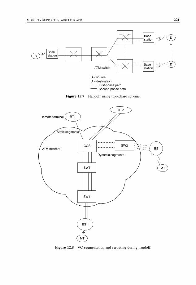
MOBILITY SUPPORT IN WIRELESS ATM 221
SBasestation
ATM switch
Basestation
Basestation
D
D
S − sourceD − destination
First-phase pathSecond-phase path
Figure 12.7 Handoff using two-phase scheme.
Remote terminal RT1
RT2
Static segments
ATM network
MT
BS1
SW1
COS
Dynamic segments
SW2BS
MTSW3
Figure 12.8 VC segmentation and rerouting during handoff.

222 TWO-PHASE COMBINED QoS-BASED HANDOFF SCHEME
handoff using two-phase protocol. We propose a combined QoS-based path optimizationscheme that activates the path optimization when the delay constraint and path extensionhops exceed the maximum value.
In a WATM network, the handoff of an MT between different BSs is the dynamicreconfiguration of the end-to-end VCs under the constraint of QoS requirements of con-nections. Since the end-to-end virtual connection is constructed on a link-by-link basis,the VC can be separated into two segments: the static and dynamic segments. This seg-mentation is illustrated in Figure 12.8 in which an MT has three active connections fromtwo Remote Terminals (RT), one connection from RT1 and two from RT2. When theMT migrates from the coverage area of BS1 to BS2, these connections are reconfiguredby creating three dynamic segments from the COS to BS2, and changing the VC rout-ing table at the COS. The COS is the mobility support switch, which is the separationpoint between the static segment and the dynamic segment. The selection of the COSis mainly on the basis of the routing optimization for the connections and their QoSrequirements. It is possible that there are several COSs for the connections. Here, weassume that there is one COS for all the connections for an MT in order to simplifythe problem.
12.3 COMPARISON OF REROUTING SCHEMES
To support mobility in WATM networks, fast and seamless handoff is crucial. Becauseof the very high transmission speed, a short connection interruption will cause a largeamount of information loss. As the population of MTs increase, the cell size will bereduced, and the handoff would occur more frequently in the future.
One of the major design issues in WATM is the support of interswitch handoff. Aninterswitch handoff occurs when a MT moves to a new BS connecting to a different switch.Recently, a two-phase handoff protocol has been proposed to support interswitch handoffin WATM networks. The aim of the two-phase handoff is to shorten the handoff delay andat the same time to use the network resources efficiently. The two-phase handoff protocolemploys path extension for each interswitch handoff, followed by path optimization ifnecessary. We propose a scheme that determines when to trigger path optimization forthe two-phase handoff.
Several connection protocols have been proposed to facilitate interswitch handoff.There are several rerouting schemes for handoff proposed for WATM networks.
The existing rerouting algorithms can be classified under four categories: cell forward-ing, virtual tree–based, dynamic rerouting, and two-phase handoff.
Yuan’s algorithm uses cell-forwarding algorithm. In cell-forwarding-based handoff, theconnection is extended from the anchor switch to the target switch during handoff. Thisscheme is fast and simple to implement. QoS degradations such as cell loss, duplicatecells, and missed sequence cells do not occur. However, since the extended path is longerthan the original one, certain QoS requirements, such as cell-transfer delay and cell-delayvariation may not be guaranteed after a handoff. In addition, data looping may occurwhen the MT moves back to the previous anchor switch later, which leads to inefficientuse of the network resources.

COMPARISON OF REROUTING SCHEMES 223
Source Routing Mobile Circuit (SRMC) algorithm uses virtual tree–based rerouting.This type of rerouting scheme creates multiple connections for a single user connection toall possible handoff candidate zones and performs an immediate rerouting. This algorithmis fast; however, it preestablishes connections to all the neighbor BSs. This may result inthe waste of network resources for handoff. For example, it may waste the bandwidth,which is one of the main resources in wireless communication.
The dynamic rerouting algorithm is based on the principle of partial reestablishmentof the user connection. Bora’s algorithm is dynamic rerouting algorithm. In dynamicrerouting scheme, a portion of the connection is rerouted at a COS. The COS is a reroutingpoint in which the new partial path meets the old path. The scheme provides only partialroute optimization and requires an implementation of a COS selection algorithm duringhandoff. The handoff latency of this scheme depends largely on selecting the COS andsetting up new VCs for the establishment of the new partial path. The delay will be highlyvariable and will depend on the number of intermediate switches and the processing loadat each switch. The delay is more noticeable in the interswitch handoff as the number ofintermediate switches increase.
On the basis of the previous three schemes, a new scheme is proposed to overcomethese three schemes’ drawback. This new scheme is a two-phase handoff. Salah’s andWong’s algorithms use this scheme. The two-phase handoff algorithm employs path exten-sion for each interswitch handoff, followed by path optimization. The advantage of thisscheme is that it provides low handoff delay and drop rate while the network resourcesare efficiently used.
We propose a scheme that determines when to trigger path optimization for the two-phase handoff. During the path optimization, the network determines the optimized pathbetween the source and the destination (i.e., the path between the COS and the currentanchor switch in Figure 12.9), and transfers the user information from the old path to thenew path. Since the MT is still communicating over the extended path via the current BS
SW2 SW1
SW1SW2
Basestation
− anchor switch− crossover switchOriginal handoff segmentNew handoff segment
Figure 12.9 Crossover switch determination.

224 TWO-PHASE COMBINED QoS-BASED HANDOFF SCHEME
while path optimization takes place, this gives enough time for the network to perform thenecessary functions while minimizing any service disruptions. Although path optimizationcan increase the network utilization by rerouting the connection to a more efficient route,transient QoS degradations such as ATM cell loss and an increase in cell-delay variationmay occur. In addition, path optimization increases the processing load of certain switchesand increases the signaling load of the network. Thus, path optimization after each pathextension may not be necessary or desirable.
To ensure a seamless path optimization, two important issues need to be addressed:
1. How to minimize service disruptions during path optimization?2. When and how often should path optimization be performed?
We propose a signaling protocol in which buffering is used at the COS and the anchorswitch during path optimization to prevent ATM cell loss and maintain cell sequencing.We also propose a path optimization scheme, which is the QoS-based path optimizationscheme. This scheme invokes the path optimization when the number of hops of thepath is greater than a certain number or when the end-to-end cell-transfer delay boundis violated.
12.4 MAINTAINING THE CELL SEQUENCE DURINGPATH OPTIMIZATION
The path optimization procedure consists of two phases, the path optimization initiationphase and the path optimization execution phase. The path optimization we propose isinitiated on the basis of the combined QoS-based scheme. In this scheme, path optimiza-tion is initiated when the delay constraint of the link has a chance to be violated or thenumber of path extension hops exceed the maximum hops. The major steps during thepath optimization execution phase involve
• computing a new path between the new source switch and the boundary switch;• determining the location of COS;• setting up a new branch connection;• transferring the user information from the old branch connection to the new one; and• terminating the old branch connection.
During the path rerouting, which includes connection setup, transferring the user infor-mation from the old branch to the new branch, and terminating the old branch connection,the cell sequence should be maintained.
When the path optimization takes place, the MT is still communicating over theextended path. This gives enough time to perform the necessary functions while min-imizing any service disruptions. In our implementation, the optimal path is the path thathas the least link delay. It is the shortest delay path between the source node and thedestination node. Dijkstra’s algorithm is used to compute the shortest path. The timecomplexity of Dijkstra’s algorithm is O(N2).

MAINTAINING THE CELL SEQUENCE DURING PATH OPTIMIZATION 225
After the new handoff path is computed, the source switch can determine the locationof the COS. On the basis of the routing information, the source switch compares theoriginal and the new path to determine the location of the COS. The COS is the one inwhich the original and the new path begin to diverge. Figure 12.9 shows an example ofthe determination of the COS. In Figure 12.9, the upper portion connection represents theoriginal handoff segment, and the lower portion connection represents the new handoffsegment. The original and the new handoff segments can be the same if the COS is thesame as the anchor switch. In this case, the current handoff segment is the optimal path;no further path optimization executions are necessary.
When the COS is determined, connection setup between the anchor switch and theCOS is performed. Connection setup is done by using the ATM UNI signaling protocol.Referring to Figure 12.10, the anchor switch first sends a signaling packet CONNECTto the COS. The COS then replies by sending CONNECT ACKNOWLEDGE (ACK)packet to the anchor switch. This message indicates that the connection setup of thenew handoff segment between the COS and the anchor switch is successful. Now thereare two segments established between the COS and the anchor switch. The connectionrerouting protocol has to reroute the data flow from the original handoff segment to thenew handoff segment. We introduce the procedure of transfer user information in theuplink and downlink to the new handoff segment in the following subsections.
The path optimization signaling protocol ensures that ATM cell sequencing is main-tained on the uplink and downlink by buffering cells at the anchor switch and the COS,respectively. The procedure of transferring user information in the uplink is as follows:
1. In the uplink, the anchor switch sends the COS a LAST(m) message, which indicatesthat no more ATM cells from the MT m will be transmitted through the original uplinkhandoff segment.
2. The anchor switch then begins to transmit ATM cells through the new handoff segment.3. The COS will not transmit any ATM cells from the new uplink segment until it has
received the LAST(m) message from the original uplink handoff segment. This ensuresthe uplink ATM cells sequencing, since the delay of the new handoff segment is shorterthan the delay of the original handoff segment. If the COS transmits ATM cells fromthe new handoff segment without receiving the LAST(m) message, the later ATMcells from the new handoff segment, which arrives first, will transmit first. The cellsequencing is then disrupted. Buffers can be used at the COS to temporarily storethe cells arriving from the new uplink handoff segments until the LAST(m) messageis received.
4. When the COS receives the LAST(m) packet, it begins to transmit ATM cells fromthe new uplink handoff segment.
5. The COS sends a LAST ACK(m) packet to the anchor switch to acknowledge thereception of the LAST(m) packet.
The procedure of transfer user information in the downlink is as follows:
1. In the downlink, the COS sends the anchor switch a LAST(m) message, which indicatesthat no more ATM cells that correspond to MT m will be transmitted through theoriginal downlink handoff segment.

226 TWO-PHASE COMBINED QoS-BASED HANDOFF SCHEME
Connect
Uplink
Downlink
Release
Crossover switch Anchor switch
CONNECT
CONNECT_ACK
LAST(m)
ATM cells
ATM cells
LAST(m)
LAST_ACK(m)
LAST_ACK
RELEASE
RELEASE_COMPLETE
Figure 12.10 Connection rerouting signaling message flow.
2. The COS then begins to transmit ATM cells through the new handoff segment.3. The anchor switch will not transmit any ATM cells from the new uplink segment
until it has received the LAST(m) message from the original uplink handoff segment.This ensures the downlink ATM cell sequencing, since the delay of the new handoffsegment is shorter than the delay of the original handoff segment. If the anchor switchtransmits ATM cells from the new handoff segment without receiving the LAST(m)

COMBINED QoS-BASED PATH OPTIMIZATION SCHEME 227
message, the later ATM cells from the new handoff segment, which arrive first, willbe transmitted first. The cell sequencing is then disrupted. Buffers can be used at theanchor switch to temporarily store the cells arriving from the new downlink handoffsegments until the LAST(m) message is received.
4. When the anchor switch receives the LAST(m) packet, it begins to transmit ATM cellsfrom the new downlink handoff segment.
5. The anchor switch sends a LAST ACK(m) packet to the anchor switch to acknowledgethe reception of the LAST(m) packet.
Once the connection rerouting process is completed, the COS sends a signaling packetRELEASE to terminate the original segment between the COS and the anchor switch. Theanchor switch sends a RELEASE COMPLETE packet to the COS after it receives theRELEASE packet. The RELEASE COMPLETE packet indicates that the original handoffsegment has been released. The path optimization process is now complete.
By employing the procedure discussed above, the cell sequence during the reroutingof a user connection due to a handoff attempt is preserved. Occasionally, cell sequencewill be broken in the WATM network. Recovery from such sequencing errors is theresponsibility of the upper-layer protocols, such as the AAL, and sometimes the userapplication layer. For data traffic, recovery may be attempted by retransmission. Fortime-sensitive traffic, the sequence error may need to be corrected by voice or videointerpolation techniques.
12.5 COMBINED QoS-BASED PATH OPTIMIZATIONSCHEME
The end-to-end path after path extension may not be optimum. These paths may leadto an inefficient use of network resources. There are different methods to initiate pathoptimization. Path optimization schemes can be classified into four types, that is, QoS-based, network-based, time-based, and handoff-based.
QoS-based path optimization schemes trigger path optimization of each mobile con-nection on the basis of its current QoS measures. For example, path optimization canbe initiated if the number of hops of the path is greater than a certain number, or ifthe end-to-end cell-transfer delay bound is violated. To implement those QoS-based pathoptimization schemes, information about the quality of the current path in terms of thedefined QoS measurement (e.g., hop count, current average delay) must be maintained bythe network. Wong proposed a QoS-based path optimization in which the path optimiza-tion is initiated when the delay constraint of the handoff segment is violated. This schemeensures that the delay of the mobile connection is always below the specified delay con-straint. Chan proposed a scheme in which the path optimization is initiated when thenumber of hops by which the path is extended is greater than the maximum number ofhops. This improves the path efficiency and at the same time allows path rerouting toefficiently utilize the network resources.
In the time-based path optimization scheme, the path optimizations are triggered attime instants that are independent of the current QoS of the connection or the utilization
228 TWO-PHASE COMBINED QoS-BASED HANDOFF SCHEME
of the network. The time instants can be deterministic or random. For example, the timebetween path optimization can be based on some random processes. In addition, it canalso be a function of the velocity of the MT, the dwell time, and the residual service timeof the mobile connection.
In the handoff-based path optimization scheme, the path optimizations are triggeredon the basis of some criteria after each interswitch handoff. Thus, it can be a function ofthe number of previous handoff, the velocity of the MT, and the residual service time.Wong proposed and analyzed three path optimization schemes: exponential, periodic, andBernoulli. These schemes provide the means of optimizing the frequency of path opti-mization with respect to the average cost per call. An analytical model and a simulationmodel are used to analyze the performance of the path optimization schemes. The sim-ulation result shows that Bernoulli path optimization scheme out performs the other twoschemes by giving the lowest expected cost per call.
Path optimization can be invoked on the basis of a combination of the above schemes.We propose a QoS-based scheme that combines Wong’s and Chan’s schemes. We com-pared the performance of these schemes and our combined QoS-based path optimizationscheme by using the following measures: handoff drop rate, average number of hops,average link delay, and rerouting delay for handoff.
This scheme invokes the path optimization when the number of path extensions isgreater than a certain number or the end-to-end cell-transfer delay bound is violated. Thisscheme ensures that during the handoff each hop meets the delay variation so that thedrop rate variable is improved. Also, even if the delay variation is not violated, the pathoptimization scheme is invoked after a certain number of path extensions. This ensuresthe efficient utilization of the network resources and avoids the loop.
We propose a combined QoS-based path optimization algorithm to improve the hand-off drop rate. In this section, we compare the QoS-based path optimization algorithmwith the existing delay-based path optimization algorithm and hop-based path optimiza-tion algorithm. We describe the algorithm of these three path optimization algorithmsas follows:
In the combined QoS-based path optimization algorithm, when there is a handoffrequest, the path extension is done first to ensure a seamless handoff. After the pathextension, the new path’s delay is the sum of the previous path delay and the delay betweenthe new source node and the previous source node. Here we assume the destination nodeis stationary during handoff. We also assume the previous path does not exceed themaximum delay limit. After the path extension rerouting, the delay of the path mayexceed the required maximum delay value. If the delay variation is violated, the pathoptimization is activated. The new shortest path, that is, the lowest delay path should befound to substitute the previous path to ensure a continuous connection. Also, after thepath extension rerouting, the total hops of the path may not be optimum, or may haveloops. This situation is caused by the large number of path extensions. The combined QoSscheme also checks if the number of path extensions exceeds the certain given number. Ifit does, then the path optimization is also activated. The given number of path extensionsis based on the system design. We use four hops in the simulation. That means pathoptimization is activated when the number of path extensions exceeds the four hops. Thisnumber is based on Chan’s proposal.

COMBINED QoS-BASED PATH OPTIMIZATION SCHEME 229
The idea of the delay-based path optimization algorithm is that the path extensioncontinues until the delay variation is violated during handoff. When a MT first requestshandoff during the call, the previous path is reserved. The rerouting path is the extensionof the previous path. That means the rerouting path is extended from the previous switchto the current switch. This is the simplest and the fastest way to do path rerouting and itensures a seamless handoff. After the path extension is completed, the new path’s delayis the sum of the previous path delay and the delay between the new source node and theprevious source node. Here we assume the destination node is stationary during handoff.We also assume the previous path does not exceed the maximum delay limitation. Afterpath extension rerouting, the delay of the path may exceed the required maximum delayvalue. This may cause the call to drop.
If the delay variation is violated, the path optimization is activated. The new shortestpath, that is, the lowest delay path should be found to substitute the previous path toensure a continuous connection.
In the hop-based algorithm, the path extension is done when there is a handoff requestuntil the number of path extensions exceeds the maximum allowed path extension hops.When the number of path extensions exceeds the maximum allowed path extension hops,path optimization is activated when there is a handoff request. This algorithm only con-siders the number of path extensions. It does not consider the delay variation to activatethe path optimization scheme.
The rerouting path searching procedure for delay-based, hop-based, and combinedrerouting algorithms is the shortest path search.
The delay-based algorithm extends the path each time when handoff occurs until thelink delay is larger than the allowed maximum delay. In our simulation, we use MAXDE-LAY to indicate the allowed maximum delay. When the MAXDELAY is large, whichmeans the traffic is not time critical, it ensures the fastest handoff and lower handoff droprate. But the number of hops of the path is not optimum. Since it extends the path eachtime when handoff is activated, it may not be the shortest path anymore. Also, the loopmay occur when the MT moves from the new source node to the original source nodeagain after the handoff. This causes a waste of network resources.
The hop-based algorithm activates path rerouting when it has maximum allowed hopsof path extensions no matter whether the delay variation is violated. This algorithmworks well when the maximum allowed delay (i.e., MAXDELAY) is set large. But whenthe MAXDELAY is small, the probability of the handoff drop is high. Since each pathextension adds the weight between new source node and old source node to the previoustotal weight of the link, it means the link delay is increased each time. If the link delay islarger than the MAXDELAY, the call is dropped. Thus, when the MAXDELAY is small,the handoff drop rate will be higher than the delay-based algorithm.
The combined QoS-based algorithm combines the delay-based and hop-based algo-rithms into one algorithm. The combined algorithm checks the delay variation every timethe MT has a handoff request. This takes advantage of the delay-based rerouting algorithm,which ensures faster handoff and lower handoff drop rate than the hop-based reroutingalgorithm. The difference between the combined algorithm and the delay-based algorithmis that the combined algorithm will activate the path rerouting when the path extensionreaches four hops. This takes advantage of the hop-based handoff algorithm, which ensures

230 TWO-PHASE COMBINED QoS-BASED HANDOFF SCHEME
the optimized path and effectively saves network resources. Also, the average hops forthe handoff request is lower than the delay-based algorithm.
The disadvantage of the combined algorithm is that it has an overhead since it needsto check the delay variation for every handoff request. So it takes longer to handlethe handoff. The trade-off is the high reliability, low drop rate, and high utilization ofnetwork resources.
These three rerouting algorithms are all sensitive to the network topology. The com-plexity of each of these three algorithms is O(N2), where N is the number of nodes inthe network.
12.6 SUMMARY
The QoS-based rerouting algorithm is designed to implement two-phase interswitch hand-off scheme for WATM networks. A path extension is used for each interswitch handoff,and the path optimization is invoked when the handoff path exceeds the delay constraintor the maximum path extension hops constraint. There are different types of path opti-mization schemes: combined QoS-based, delay-based, hop-based path rerouting schemes,and QoS combined path optimization scheme for WATM network. The QoS combinedpath optimization scheme focuses on the problems related to the support of mobility inthe WATM network. This scheme determines when to trigger path optimization for thetwo-phase handoff and when to minimize service disruption during path optimization.
PROBLEMS TO CHAPTER 12
Two-phase combined QoS-based handoff scheme
Learning objectives
After completing this chapter, you are able to
• demonstrate an understanding of a WATM network;• explain hard and soft handoff;• explain forward and backward handoff;• explain combined QoS-based path optimization scheme; and• explain different types of path optimization schemes.
Practice problems
12.1: What are the major components in a WATM network?12.2: How is a hard handoff executed?12.3: How is a soft handoff executed?12.4: How is a forward handoff performed?12.5: How is a backward handoff performed?12.6: What is a handoff using full reestablishment?

PROBLEMS TO CHAPTER 12 231
12.7: What is a handoff using multicasting?12.8: What is a handoff using connection extension?12.9: What is a handoff using partial reestablishment?
12.10: What is a handoff using two-phase protocol?12.11: What is a combined QoS-based path optimization scheme?12.12: What are the types of path optimization schemes?
Practice problem solutions
12.1: There are two major components in a WATM network: a radio access layer pro-viding high-bandwidth wireless transmission with appropriate MAC, DLC, and soon and a mobile ATM network for interconnection of BSs (APs) with appropriatesupport of mobility related functions, such as handoff and location management.
12.2: In a hard handoff, the MT switches the communication from the old link to thenew link. Thus, there is only one active connection from the MT at any time. Thereis a short interruption in the transmission. This interruption should be minimizedin order to make the handoff seamless.
12.3: In a soft handoff, the MT is connected simultaneously to two APs. As it movesfrom one cell to another, it ‘softly’ switches from one BS to another. When con-nected to two BSs, the network combines information received from two differentroutes to obtain better quality. This is commonly referred to as macrodiversity.
12.4: In a forward handoff, after the MT decides the cell to which it will make a handoff,it contacts the BS controlling the cell. The new BS initiates the handoff signalingto link the MT from the old BS. This is especially useful if the MT suddenly losescontact with the current BS.
12.5: In a backward handoff, after the MT decides the cell to which it attempts to makea handoff, it contacts the current BS, which initiates the signaling to handoff tothe new BS.
12.6: A handoff using full reestablishment occurs in a connection-oriented wireless envi-ronment, in which virtual circuits are established from the source to the destination.The data follows the path that has been set up, and an in-order delivery is guar-anteed. If a handoff is to occur, the old virtual connection is torn down, andan entirely new virtual circuit is set up from the current source to the currentdestination. Since both ends are explicitly involved, this handoff scheme is nottransparent. Severe traffic interruptions are experienced and hence this scheme isnot recommended.
12.7: A handoff using multicasting is used in both the connection-oriented and connec-tionless scenarios. In the case of a WATM environment, multicasting is used toestablish links to all BSs that are neighboring the BS that is currently controllinga MT. Subsequently, in whichever direction the MT moves, a handoff path hasalready been established. Also, since the data is being multicast, it continues toflow without any interruption. This scheme ensures a lossless and seamless hand-off. However, since data is being multicast to the entire set of nodes most of whichis unused, bandwidth is being utilized very inefficiently. Also, if an MT is at the

232 TWO-PHASE COMBINED QoS-BASED HANDOFF SCHEME
edge of two cells, it is very likely that it might get two copies of the data packets.This leads to other complications like BS synchronization.
12.8: The basic idea of the handoff using connection extension scheme is that the localpaths are more affordable than the global paths. When an MT migrates from oneBS to another, the old BS extends the connection to the new BS. The obviousdisadvantage of this method is that the new path to the MT is not an optimal path.
12.9: A handoff using partial reestablishment uses the concept of a COS. The new BSdoes a partial reestablishment of the connection by opening a connection to theCOS. This way it attempts to reuse as much of the existing connection as possible.The old partial path is then torn down and the resources are released. Bufferingis done at the COS.
12.10: A handoff using two-phase protocol combines the connection extension and partialreestablishment schemes. The two-phase handoff protocol consists of two phases:path extension and path optimization. Path extension is performed for each inter-switch handoff. Path optimization is activated when the delay constraint or othercost is violated.
12.11: A combined QoS-based path optimization scheme activates the path optimizationwhen the delay constraint and path extension hops exceed a maximum value.
In the combined QoS-based path optimization algorithm, when there is a hand-off request, the path extension is done first to ensure a seamless handoff. Afterthe path extension, the new path’s delay is the sum of the previous path delay andthe delay between the new source node and previous source node.
12.12: Path optimization schemes can be classified into four types: QoS-based, network-based, time-based, and handoff-based. QoS-based path optimization schemes trig-ger path optimization of each mobile connection on the basis of its current QoSmeasures.

References
A. S. Acampora and M. Naghshineh (1994) An architecture and methodology for mobile-executedhandoff in cellular ATM networks. IEEE JSAC, 12, 1365–1375.
I. F. Akyildiz, J. McNair, J. Ho, H. Uzunalioglu and W. Wang (1998) Mobility management incurrent and future communications networks. IEEE Network, 12(4), 39–49.
I. Akyildiz, H. Uzunalioglu and M. D. Bender (1999) Handover management in low earth orbit(LEO) satellite networks. Mobile Networks and Applications, 4, 301–310.
B. A. Akyol and D. C. Cox Rerouting for Handoff in a Wireless ATM Network InternationalConference on Universal Personal Communications, 1996, pp. 374–379. URL: http://wireless.stanford.edu/∼akyol.
G. Anastasi, L. Lenzini, E. Mingozzi, A. Hettich and A. Kramling (1998) MAC protocols for wide-band wireless local access: evolution toward wireless ATM. IEEE Personal Communications,5(5), 53–64.
A. A. Androutsos, T. K. Apostolopoulos and V. C. Daskalou (2000) Managing the network stateevolution over time using CORBA environment. IEEE Journal on Selected Areas in Communi-cations, 18(5), 654–663.
E. Ayanoglu (1999) Wireless broadband and ATM systems. Computer Networks, 31, 395–409.S. Batistatos, K. Zygourakis, F. Panken, K. Raatikainen and S. Trigila (1999) TINA architecture
extensions to support terminal mobility. Proc. IEEE Telecommunications Information NetworkingArchitecture Conference, pp. 34–45.
S. Boumerdassi and A.-L. Beylot (1999) Adaptive channel allocation for wireless PCN. MobileNetworks and Applications, 4, 111–116.
J. Bray and C. F. Sturman (2000) Bluetooth: Connect Without Cables, Prentice Hall PTR, UpperSaddle River, NJ.
M. Breugst, L. Faglia, O. Pyrovolakis, I. S. Venieris and F. Zizza (1999) Towards mobile serviceagents within and advanced broadband IN environment. Computer Networks, 31(19), 2037–2052.
J. Broch, D. Johnson and D. Maltz (1998) The Dynamic Source Routing Protocol for Mobile AdHoc Networks, Internet Draft, draft-ietf-manet-dsr-00.txt, March 13 1998; Work in progress.
J. Broch, D. Maltz, D. B. Johnson, Y.-C. Hu and J. Jetcheva (1998) A performance comparison ofmulti-hop wireless ad hoc network routing protocols. Proceedings of the Fourth Annual ACM/IEEE International Conference on Mobile Computing and Networking (MobiCom ’98),October 25, 1998.
Mobile Telecommunications Protocols For Data Networks. Anna HacCopyright 2003 John Wiley & Sons, Ltd.
ISBN: 0-470-85056-6

234 REFERENCES
A. T. Campbell, R. R.-F. Liao and Y. Shobatake Supporting QoS Controlled Handoff in Mobiware.URL: http://www.ctr.columbia.edu/∼liao/project/hdoff/signal abstract.html.
K. S. Chan, S. Chan and K. T. Ko (1998) Hop-limited handoff scheme for ATM-based broadbandcellular networks. Electronics Letters, 34(1), 26–27.
K.-S. Chan and S. Chan (2000) An efficient handoff management scheme for mobile wireless ATMnetworks. IEEE Transactions on Vehicular Technology, 49(3), 799–815.
F. G. Chatzipapadopoulos, M. K. Perdikeas and I. S. Venieris (2000) Mobile agent and CORBAtechnologies in the broadband intelligent network. IEEE Communications Magazine, 38(6),116–124.
T.-W. Chen and M. Gerla Global state routing: a new routing scheme for ad-hoc wireless networks.Proc. IEEE ICC ’98, 1998, pp. 171–175.
I.-R. Chen, T.-M. Chen and C. Lee (1998) Agent-based forwarding strategies for reducing locationmanagement cost in mobile networks. Proc. IEEE International Conference on Parallel andDistributed Systems, pp. 266–273.
C.-C. Chiang (1997) Routing in clustered multihop. Mobile Wireless Networks with Fading ChannelProc. IEEE SICON ’97, April 1997, pp. 197–211.
J. Chuang and N. Sollenberger (1999) Wideband wireless data access based on OFDM and dynamicpacket assignment. IEEE Wireless Communications and Networking Conference, 2, 757–761.
Composite Capabilities/Preference Profiles: Requirements and Architecture, W3C Working Draft,July 21 2000. URL: http://www.w3.org.
Concordia. URL: http://www.meitca.com/HSL/Projects/Concordia.S. Corson, S. Papademetriou, P. Papadopoulos, V. Park and A. Qayyum (1998) An Internet MANET
Encapsulation Protocol (IMEP) Specification, Internet Draft, draft-ietf-manet-imep-spec-01.txt,August 7 1998; Work in progress.
G. Coulson (1999) A configurable multimedia middleware platform. IEEE Multimedia, 6(1), 62–76.A. Dornan (2000) The Essential Guide to Wireless Communications Applications, Prentice Hall
PTR, Upper Saddle River, NJ.C. Dou, Y.-P. Chen and H.-K. Chen (2001) An agent-based platform for dynamic service provi-
sioning in 3G mobile systems: scenarios and performance analyses. Proc. 15th IEEE InternationalConference on Information Networking, pp. 883–888.
R. Dube, C. Rais, K.-Y. Wang and S. Tripathi (1997) Signal stability based adaptive routing (SSA)for ad-hoc mobile networks. IEEE Personal Communications, 4(1), 36–45.
H. J. R. Dutton and P. Lenhard (1995) Asynchronous Transfer Mode, Prentice Hall, New York.W. K. Edwards (1999) Core Jini, Prentice Hall PTR, Upper Saddle River, NJ.K. Y. Eng, M. J. Karol, M. Veeraraghavan, E. Ayanoglu, C. B. Woodworth, P. Pancha and R. A.
Valenzuela (1995) BAHAMA: A broadband ad-hoc wireless ATM local area network. ICC ’95,pp. 1216–1223.
Extensible Markup Language (XML) 1.0, W3C Recommendation, October 6 2000. URL: http://www.w3.org.
A. Fladenmuller and R. De Silva (1999) The effect of mobile IP handoffs on the performance ofTCP. Mobile Networks and Applications, 4, 131–135.
V. K. Garg (2000) IS-95 CDMA and cdma 2000, Prentice Hall PTR, Upper Saddle River, NJ.R. Ghai and S. Singh (1994) An architecture and communication protocol for picocellular networks.
IEEE Personal Communication, 1(3), 36–46.Z. Haas and M. Pearlman (1998) The Zone Routing Protocol (ZRP) for Ad Hoc Networks, Internet
Draft, draft-ietf-manet-zone-zrp-01.txt, August, 1998; Work in progress.A. Hac (2000) Multimedia Applications Support for Wireless ATM Networks, Prentice Hall PTR,
Upper Saddle River, NJ.

REFERENCES 235
A. Hac and B. L. Chew (2000) Demand assignment multiple access protocols for wireless ATMnetworks. Proc. IEEE Vehicular Technology Conference, Boston, MA, September 24–28 2000,pp. 237–241.
A. Hac and B. L. Chew (2001) ARCMA–adaptive request channel multiple access protocol forwireless ATM networks. International Journal of Network Management, 11(6), 333–363.
A. Hac and J. Peng (2001) A two-phase combined QoS-based handoff scheme in wireless ATMnetwork. International Journal of Network Management, 11(6), 309–330.
A. Hac and J. Peng (2001) Handoff in wireless ATM network. International IEEE Conference onThird Generation Wireless and Beyond, San Francisco, CA, May 30–June 2, 2001, pp. 894–899.
A. Hac and Y. Zhang (2002) Reducing signaling traffic in wireless ATM networks through handoffscheme improvement. International Journal of Network Management, 12(5), in press.
A. Hac and Y. Zhang (2001) Signaling QoS in wireless ATM network. International IEEE Con-ference on Third Generation Wireless and Beyond, San Francisco, CA May 30–June 2, 2001,pp. 906–911.
A. Hac and Z. Zhu (1999) Performance of routing schemes in wireless personal networks. Inter-national Journal of Network Management, 9(2), 80–105.
L. Hagen, J. Mauersberger and C. Weckerle (1999) Mobile agent based service subscription andcustomization using the UMTS virtual home environment. Computer Networks, 31(19),2063–2078.
M. Hannikainen, J. Knuutila, A. Letonsaari, T. Hamalainen, J. Jokela, J. Ala-Laurila and J. Saarinen(1998) TUTMAC: A medium access control protocol for a new multimedia wireless local areanetwork. Proc. Ninth IEEE International Symposium on Personal, Indoor and Mobile RadioCommunications, 2, 592–596.
C. Hedrick (1988) Routing Information Protocol, RFC 1058, June 1988.IBM: Aglets Software Development Kit. URL: http://www.trl.ibm.co.jp/aglets.M. Inoue, G. Wu and Y. Hase (1999) IP-based high-speed multimedia wireless LAN prototype
for broadband radio access integrated network (BRAIN). Proc. 50th IEEE Vehicular TechnologyConference, 1, 357–361.
International Standard, ISO/IEC 8802-11, ANSI/IEEE, Std 802.11, 1999.Internet Protocol, RFC 791, Information Sciences Institute, September 1981.A. Iwata, C.-C. Ching, G. Pei, M. Gerla and T.-W. Chen (1999) Scalable routing strategies for ad
hoc wireless networks. IEEE Journal on Selected Areas in Communications, 17(8), 1369–1379.P. Jacquet, P. Muhlethaler and A. Qayyum (1998) Optimized Link State Routing Protocol, Internet
Draft, draft-ietf-manet-olsr-00.txt, November 18 1998; Work in progress.B. Jennings, R. Brennan, R. Gustavsson, R. Feldt, J. Pitt, K. Prouskas and J. Quantz (1999) FIPA-
compliant agents for real-time control of intelligent network traffic. Computer Networks, 31(19),2017–2036.
M. Jiang, J. Li and Y. C. Tay (1998) Cluster Based Routing Protocol (CBRP) Functional Specifi-cation, Internet Draft, draft-ietf-manet-cbrp-spec-00.txt, August 1998; Work in progress.
M. Jiang, J. Li and Y. C. Tay (1999) Cluster Based Routing Protocol, August 1999, IETF Draft.URL: http://www.ietf.org/internet-drafts/draft-ietf-manet-cbrp-spec-01.txt.
M. Joa-Ng and I.-T. Lu (1999) A peer-to-peer zone-based two-level link state routing for mobilead hoc networks. IEEE Journal on Selected Areas in Communications, 17(8), 1415–1425.
D. Johnson and D. Maltz (1996) Truly seamless wireless and mobile host networking. Protocolsfor adaptive wireless and mobile networking. IEEE Personal Communications, 3(1), 34–42.
D. B. Johnson (1994) Routing in ad hoc networks of mobile hosts. Proceedings of the IEEE Work-shop on Mobile Computing Systems and Applications, December, 1994.

236 REFERENCES
D. Johnson (1996) Dynamic source routing in ad hoc wireless networks, Mobile Computing, KluwerAcademic Publishers, Boston, MA.
D. B. Johnson and D. A. Maltz (1996) Dynamic source routing in ad hoc networks. In Mobile Com-puting, T. Imielinski and H. Korth (eds), Kluwer Academic Publishers, Boston, MA, pp. 152–181.
D. B. Johnson and D. A. Maltz (1999) The Dynamic Source Routing Protocol for Mobile Ad HocNetworks, October 1999, IETF Draft. URL: http://www.ietf.org/internet-drafts/draft-ietf-manet-dsr-03.txt.
A. Kalaxylos, S. Hadjiefthymiades and L. Merakos (1998) Mobility management and control pro-tocol for wireless ATM networks. IEEE Network, 12(4), 19–27.
M. R. Karim (2000) ATM Technology and Services Delivery, Prentice Hall PTR, Upper SaddleRiver, NJ, pp. 141–256.
M. Karol, Z. Liu and K. Y. Eng (1995) Distributed-queuing request update multiple access(DQRUMA) for wireless packet (ATM) networks. Proc. IEEE ICC International Conferenceon Communications, Seattle, WA, June 1995, pp. 1224–1231.
J. Keogh (2000) The Essential Guide to Networking, Prentice Hall PTR, Upper Saddle River, NJ.P. Kumar and L. Tassiulas (2000) Mobile multi-user ATM platforms: architectures, design issues,
and challenges. IEEE Network, 14(2), 42–50.T. Kurz, J.-Y. Le Boudec and H. J. Einsiedler (1998) Realizing the benefits of virtual LANs by
using IPv6. Proc. 1998 IEEE International Zurich Seminar on Broadband Communications,pp. 279–283.
J. Landru, H. Mordka and P. Vincent (1998) MONACO – modular open network agent for controloperations, Proc. IEEE Network Operations and Management Symposium, 2, 600–609.
D. C. Lee, D. L. Lough, S. F. Midkiff, N. J. Davis, IV and P.E. Benchoff (1998) The next gener-ation of the Internet: aspects of the Internet protocol version 6. IEEE Network, 12(1), 28–33.
M. Lerner, G. Vanecek, N. Vidovic and D. Vrsalovic (2000) Middleware Networks, Kluwer Aca-demic Publishers, Boston, MA.
B. C. Lesiuk Ad Hoc Networks. URL: http://ghost.hn.org.K. H. Le, S. Norskov, L. Dittmann and U. Gliese (1998) Base station MAC with APRMA proto-
col for broadband multimedia ATM in micro/pico-cellular mobile Networks. Proc. 48th IEEEVehicular Technology Conference, 1(1), 234–238.
S. Lipperts and A. S.-B. Park (1999) An agent-based middleware – a solution for terminal and usermobility. Computer Networks, 31(19), 2053–2062.
Microsoft Technologies: Distributed Component Object Model. URL: http://www.microsoft.com/com/tech/dcom.asp.
B. A. Miller and C. Bisdikian (2000) Bluetooth Revealed, Prentice Hall PTR, Upper SaddleRiver, NJ.
S. Murthy and J. J. Garcia-Luna-Aceves, An Efficient Routing Protocol for Wireless Networks,ACM Mobile Networks and Application Journal, Special Issue on Routing in Mobile Commu-nication Networks, October 1996, pp. 183–97.
H. Ohtsuka, T. Oono, Y. Kondo, O. Nakamura and T. Tanaka (1999) Potential wireless technolo-gies in mobile communications. Proc. IEEE International Conference on Communications, 2,1121–1125.
K. Pahlavan, P. Krishnamurthy, A. Hatami, M. Ylianttila, J. P. Makela, R. Pichna and J. Vallstron(2000) Handoff in hybrid mobile data networks. IEEE Personal Communications, 7(2), 34–47.
V. D. Park and M. S. Corson (1997) A highly adaptive distributed routing algorithm for mobilewireless networks. Proc. INFOCOM ’97, April 1997.
V. Park and S. Corson (1998) A performance comparison of TORA and ideal link state routing.Proceedings of IEEE Symposium on Computers and Communication ’98, June, 1998.

REFERENCES 237
V. Park and S. Corson (1998) Temporally-ordered routing algorithm (TORA) version 1 functionalspecification, Internet Draft, draft-ietf-manet-tora-spec-01.txt, August 7 1998; Work in progress.
M. K. Perdikeas, F. G. Chatzipapadopoulos, I. S. Venieris and G. Marino (1999) Mobile agentstandards and available platforms. Computer Networks, 31(19), 1999–2016.
C. Perkins and E. Royer (1998) Ad Hoc On Demand Distance Vector (AODV) Routing, InternetDraft, draft-ietf-manet-aodv-02.txt, November 20 1998; Work in progress.
C. E. Perkins and P. Bhagwat (1994) Highly dynamic destination-sequenced distance-vector routing(DSDV) for mobile computers. Computer Communication Review, 24(4), 234–244.
C. E. Perkins and P. Bhagwat (1994) Highly dynamic destination-sequenced distance-vector routing(DSDV) for mobile computers. Proceedings of the SIGCOMM 94 Conference on Communications,Architectures, Protocols and Applications, August, 1994, pp. 234–244.
C. E. Perkins, E. M. Royer and S. R. Das (1999) Ad Hoc On-demand Distance Vector Routing,October 1999, IETF Draft. URL: http://www.ietf.org/internet-drafts/draft-ietf-manet-aodv-04.txt.
D. Petras and A. Kramling (1997) Wireless ATM: performance evaluation of DSA++ MAC pro-tocol with fast collision resolution by a probing algorithm. International Journal of WirelessInformation Networks, 4(4), 215–223.
D. Prevedourou, K. Zygourakis, S. Efremidis, G. Stamoulis, D. Kalopsikakis, A. Kyrikoglou,V. siris, M. Anagnostou, L. Tzifa, T. Louta, P. Demestichas, N. Liossis, A. Kind, K. Valtari,H. Jormakka and T. Jussila (1999) Use of agent technology in service and retailer selection in apersonal mobility context. Computer Networks, 31(19), 2079–2098.
R. Ramjee, T. F. La-Porta, J. Kurose and D. Towsley (1998) Performance evaluation of connectionrerouting schemes for ATM-Based wireless networks. IEEE/ACM Transactions on Networking,6(3), 249–261.
Resource Description Framework (RDF) 1.0, W3C Candidate Recommendation, March 27 2000.URL: http://www.w3.org.
E. M. Royer and C.-K. Toh (1999) A review of current routing protocols for ad hoc mobile wirelessnetworks. IEEE Personal Communications, 6(2), 46–55.
I. Rubin and C. W. Choi (1997) Impact of the location area structure on the performance of sig-naling channels in wireless cellular networks. IEEE Communication Magazine, 35(2), 108–115.
M. Sadiku and M. Ilyas (1995) Simulation of Local Area Networks, CRC Press, FL, Boca Raton.K. Salah and E. Drakoponlos (1998) A Two-phase Inter-Switch Handoff scheme for wireless ATM
networks. IEEE ATM ’98 Workshop Proceedings, pp. 708–713.D. C. Schmidt and F. Kuhns (2000) An overview of the real-time CORBA specification. IEEE
Computer, 33(6), 56–63.J. Sharony (1996) An architecture for mobile radio networks with dynamically changing topology
using virtual subnets. Journal of Special Topics in Mobile Networks and Applications (MONET)1(1), pp. 75–86.
J. Sharony (1996) A mobile radio network architecture with dynamically changing topology usingvirtual subnets. Proceedings of ICC ’96, pp. 807–812.
B. S. Suh and Shin (1998) Dynamic scope location tracking algorithm for mobile PNNI scheme inwireless ATM networks. Electronics Letters, 34(17), 1643–1644.
T. Sukuvaara, P. Mahonen and T. Saarinen (1999) Wireless internet and multimedia services sup-port through two-layer LMDS system. IEEE International Workshop on Mobile MultimediaCommunications, pp. 202–207.
A. S. Tanenbaum (1996) Computer Networks, Prentice Hall, New York, pp. 348–352.C.-K. Toh (1996) A novel distributed routing protocol to support ad hoc mobile computing. Proc.
1996 IEEE 15th Annual Int’l. Phoenix Conf. Comp. and Commun., March 1996, pp. 480–486.C.-K. Toh (1997) Wireless ATM and AD-HOC Networks, Kluwer Academic Publishers, Boston, MA.

238 REFERENCES
A. Umar (1997) Object-Oriented Client/Server Internet Environments, Prentice Hall PTR, UpperSaddle River, NJ.
M. Van der Heijden and M. Taylor (2000) Understanding WAP, Artech House, Boston, MA.Voyager. URL: http://www.objectspace.com/products/voyager.Z. Wang and J. Crowcroft (1996) Quality-of-service routing for supporting multimedia applications.
IEEE Journal on Selected Areas in Communications, 14(7), 1228–1233.L. Wang and M. Hamdi (1998) HAMAC: An adaptive channel access protocol for multimedia
wireless networks. Proc. Seventh IEEE International Conference on Computer Communicationsand Networks, pp. 404–411.
S. Weinstein, M. Suzuki, J. R. Redlich and S. Rao (1998) A CORBA based architecture for QoS-sensitive networking. Proc. IEEE International Zurich Seminar on Broadband Communications,ETH, Zurich, Switzerland, pp. 201–208.
Wireless Application Protocol Architecture Specification, WAP Forum, April 30, 1998. URL:http://www.wapforum.org.
Wireless Application Protocol Push Architectural Overview, WAP Forum, November 8 2000. URL:http://www.wapforum.org.
Wireless Application Protocol Wireless Application Environment Overview, WAP Forum, March29, 2000. URL: http://www.wapforum.org.
Wireless Application Protocol Wireless Telephony Application Specification, WAP Forum, July 72000. URL: http://www.wapforum.org.
P. T. Wojciechowski and P. Sewell (2000) Nomadic pict: language and infrastructure design formobile agents. IEEE Concurrency, 2, 42–52.
W. S. V. Wong and C. B. Henry (1998) Performance evaluation of path optimization schemes forinter-switch handoff in wireless ATM networks. Proc. ACM/IEEE MobiCom ’98, Dallas, TX,October 1998, pp. 242–251.
W. S. V. Wong and V. C. M. Leung (1999) A path optimization signaling protocol for inter-switchhandoff in wireless ATM networks. Computer Networks, 31, 975–984.
F. Wu Soft Handoff of Wireless ATM. URL: http://www.ctr.columbia.edu/∼campbell/e6950/reprot ifong.html.
C.-Q. Yang and A. V. S. Reddy (1995) A taxonomy for congestion control algorithms in packetswitching networks. IEEE Network, 9(4), 34–45.
R. Yuan and S. K. Biswas (1996) A signaling and control architecture for mobility support inwireless ATM networks. Proceedings of IEEE ICC ’96, Dallas, TX, 1996, pp. 478–486.
Index
AB-ALLOCATOR 8–9AB-ANT 8–9AB-QUANTIFIER 8Access ID 62Access Network (AN) 13, 23, 29Access Point (AP) 41, 55, 58, 139, 144, 160,
181, 182, 183, 185, 186, 187, 189, 191,195, 214, 218, 231
acknowledgement (ACK) 42, 57, 59, 62, 66Acknowledgement Request (ACKR) 58ACL link 146Ad Hoc Mode 145Ad hoc On-demand Distance Vector Routing
(AODV) 174–175ad hoc topology 41Adaptive Request Channel Multiple Access
(ARCMA) 55, 60–71admission control 38advanced service provisioning 1Agent-Based Mobile Access to Multimedia
Information Services (AMASE) 17, 19,20, 21–22
Agent Communication Language 5agent directory (AD) 18, 21, 22agent manager (AM) 18, 19Agent Transfer Protocol (ATP) 2agent 1–2agent-based load control strategies 5agent-based middleware 17agent-based service implementation 11Agents System (AS) 17Aglets (Agent applets) 1, 2ALLOCATOR agent 5AMASE Agent Platform 17ant colony optimization 8Application Programming Interface (API) 2Associativity-Based Routing (ABR)
176–177, 215Asynchronous Connectionless (ACL) 146,
149, 152, 155, 161, 162asynchronous service 41
Asynchronous Transfer Mode (ATM) 41,178, 181, 182, 183, 185, 187, 191, 192,193, 194, 195, 199, 200, 201, 202, 203,204, 205, 206, 207, 208, 209, 210, 211,213, 214, 216, 224, 225, 226, 227
ATM Adaptation Layer (AAL) 62, 216, 227ATM Forum 41, 215auction algorithm 7auction process 6–7Automatic Repeat Request (ARQ) 56Available Bit Rate (ABR) 50, 55, 69, 215,
216
backbone network 41Base Station (BS) 37, 38, 40, 46, 55, 59, 62,
63, 163, 181, 182, 183, 191, 193, 196,199, 200, 201, 202, 203, 205, 206, 207,208, 209, 211, 218, 219, 223, 232
Basic Service Area (BSA) 58Basic Service Set (BSS) 144, 160Binary Exponential Backoff (BEB) 61, 62bit rate 33
adaptation 38blackboards 19Bluetooth 146–158, 161, 162
architecture 147–152protocol stack 147–148
Break-Make 182, 206, 207Broadband-Integrated Services Digital Network
(B-ISDN) 17, 182Broadband Intelligent Peripheral (B-IP) 16Broadband Radio Access Integrated Network
(BRAIN) 55, 58Broadband Radio Access Network (BRAN)
40, 46Broadband Service Control Point (B-SCP)
16, 17Broadband Service Resource Function (B-SRF)
15Broadband Service Switching and Control
Point (B-SS & CP) 16, 17Broadband Service Switching Point
(B-SSP) 16
Mobile Telecommunications Protocols For Data Networks. Anna HacCopyright 2003 John Wiley & Sons, Ltd.
ISBN: 0-470-85056-6

240 INDEX
Broadband Video Telephone (BVT) 17broadband wireless access 40broadcast query and await-reply (BQ-REPLY)
176–177broadcast scope of a workgroup 34broadcast scope 34
Call Control and Signaling (CCS) 184, 185Call Control/Service Switching Functions
(CCF/SSF) 15CAM priority 46Carrier Sense Multiple Access (CSMA) 57Carrier Sense Multiple Access with Collision
Avoidance (CSMA/CA) 41Cascading Style Sheets (CSS) 76, 77Cascading Style Sheets Level 2 (CSS2) 76CC/PP Exchange Protocol 123, 133, 134Central Processor Unit (CPU) 73, 172Chain Routing Algorithm 199–210Channel Access Code (CAC) 147channel assignment 38Character Data (CDATA) 112Clear To Send (CTS) 43Client Capabilities Query 107Cluster-Based Routing protocol (CBRP)
173–174cluster-head 167, 173, 174Cluster-head Gateway Switch Routing (CGSR)
168Code-Division Multiple Access (CDMA) 192collision 42, 43Common Gateway Interface (CGI) 94–95Common Object Request Broker Architecture
(CORBA) 2, 12, 14, 15, 16, 24, 29communication manager (CM) 18, 19communication service 2Composite Capability/Preference Profile
(CC/PP) 80, 111, 119–137concept navigation 116Concordia 1connection establishment 197
full 197multicast 197partial 197
Conneg (Content Negotiation) 125Constant Bit Rate (CBR) 50, 55, 59, 61, 62,
63, 66, 68, 215, 217Content Format 86Contention Free Period (CFP) 44contention phase 44Contention Window (CW) 42, 43Control and Switching Unit (CSU) 183Converter Agent (CA) 25correspondent host (CH) 182
Cross ATM Switch Link (CASL) 201, 202,209
crossover switch (COS) 182, 185–189, 193,202, 206, 207, 208, 219, 220, 222, 223,224, 225, 226, 227, 232
Customer Premises Equipment 16customer system 1
Data Downstream (DD) 62data encapsulation 82Data Link Control (DLC) 213, 216, 231Data Link Layer 145data object 111Dedicated Inquiry Access Code (DIAC) 147Demand Assignment Multiple Access (DAMA)
55Destination-Sequenced Distance-Vector
Routing (DSDV) 164–166, 168, 170,174, 175, 177
Device Access Code (DAC) 147Digital Audio Broadcasting (DAB) 37Digital Video Broadcasting (DVB) 37Direct Sequence Spread Spectrum (DSSS)
141, 142, 145, 157Directed Acyclic Graph (DAG) 171discovery protocols 28distance-vector routing 166Distributed Agent Environment (DAE) 2, 24distributed AMASE Agent Environment 17Distributed Component Object Model (DCOM)
3Distributed Coordination Function (DCF) 41distributed IN architecture 16Distributed Interframe Space (DIFS) 42Distributed Object Technology (DOT) 11, 12,
14, 29, 30Distributed Processing Environment (DPE)
11, 24Distributed Queuing Request Update Multiple
Access (DQRUMA) protocol 60, 61, 62,63
Distribution System Medium (DSM) 144, 160Distribution System Service (DSS) 144, 160DISTRIBUTOR agent 5Document Type Definition (DTD) 114, 115domain name system (DNS) 121downlink channel 48downlink signaling 48Dublin Core Element Set 116Dublin Core Metadata Initiative 116dynamic agent downloading 1Dynamic Host Configuration Protocol (DHCP)
33, 34, 35, 37, 50Reconfigure 35

INDEX 241
Reply 35Request 35Server 35Workgroup Address Extension 35
Dynamic Host Configuration Protocol version6 (DHCPv6) 35, 52
Dynamic Packet Assignment (DPA) 33, 37,38
Dynamic Routing Protocol (DRP) 175–176Dynamic Slot Assignment (DSA++) 46, 48,
49, 51Dynamic Source Routing Protocol (DSRP)
171–173, 175, 177
elimination phase 44, 46Elimination Yield – Non-Preemptive Priority
Multiple Access (EY-NPMA) 44, 46, 53encapsulated multicast packet 36entry point 1–2European Telecommunications Standards
Institute (ETSI) 41, 44, 46, 143Extended Service Set (ESS) network 144Extensible Markup Language (XML) 74, 76,
78–85, 95, 111–114, 115, 116, 120, 122,127, 128, 129, 134, 135, 136
Extensible Protocol (XP) 82, 83Extensible Stylesheet Language (XSL) 76extensible-HTML (XHTML) 80, 126, 128
Fair Weighted Queuing 50Fast Fourier Transform (FFT) 33, 37field programmable gate arrays (FPGA) 58First Come First Served (FCFS) 50First In First Out (FIFO) 62Fisheye State Routing (FSR) 167flexible broadcast scope for workgroups 34flexible broadcast scope 33Footprint Handover Rerouting Protocol
(FHRP) 189–190Footprint Rerouting (FR) 189Forward Error Correction (FEC) 56frequency hop synchronization (FHS) 149,
150, 151, 155, 161Frequency Hopping Spread Spectrum (FHSS)
141, 142, 145, 157
General Equilibrium Theory 6General Inquiry Access Code (GIAC) 147General Packet Radio Service (GPRS) 181generic access profile (GAP) 153, 154Generic Identifier (GI) 113Global State Routing (GSR) 166–167Global System for Mobile communications
(GSM) 152, 153
Grasshopper 1Group Membership Report 35Gaussian Frequency Shift Keying (GFSK)
146
handheld wireless devices 74handoff 181–196
chaining 187, 191–194optimistic 187ordered 187predictive 187–188
hidden station problem 43Hierarchical State Routing (HSR) 167High Performance Radio LAN (HIPERLAN)
41HIPERLAN Type 2 44, 46home agent 36Hop-Limited Scheme (HLS) 191, 193, 203,
204, 205, 208, 210Host Controller Interface (HCI) 148, 151,
156, 157, 161host 1–2HTTP Extension Framework 123, 130HTTP-NG (Network Group) 76, 77, 84, 134Hybrid and Adaptive MAC (HAMAC) 55,
59, 60Hybrid Fiber Radio (HFR) 40HyperText Markup Language (HTML) 76,
77, 79, 93, 94, 95HyperText Transfer Protocol (HTTP) 2, 74,
78, 84, 85, 94, 95, 101, 122, 123, 129,130, 132, 133
IEEE 802.11 33, 41–44, 50, 142–145, 157,159, 160
IETF Policy on Character Sets and Language123
Independent BSS (IBSS) 144, 145, 160Industrial, Scientific and Medical (ISM) 140,
146Infrared (IR) 139, 140, 141, 142infrared data association (IrDA) 141, 159Infrastructure Mode 145infrastructure-based topology 41inquiry access code (IAC) 147, 149intelligent agents 11, 30Intelligent Network (IN) 4, 10–13
overloads 4Intelligent Network Application Protocol
(INAP) 13, 14Intelligent Peripheral (IP) 4Interactive Multimedia Retrieval (IMR) 17International Telecommunications Union (ITU)
140, 214

242 INDEX
Internet Assigned Numbers Authority (IANA)125
Internet Control Message Protocol version 6(ICMPv6) 35
Internet Engineering Task Force (IETF) 81,123, 125
Internet Inter – ORB Protocol (IIOP) 2–3Internet MANET Encapsulation Protocol
(IMEP) 170, 177Internet Mobile Ad hoc Networking (MANET)
Encapsulation Protocol (IMEP)Internet Protocol (IP) 3, 36, 152, 170Internet Protocol version 4 (IPv4) 34, 37Internet Protocol version 6 (IPv6) 33, 34, 35,
37, 50Inverse Fast Fourier Transform (IFFT) 37
Java 1, 11, 28, 30, 31Agent Environment (JAE) 20RMI (Remote Method Invocation) 28Virtual Machines (JVM) 18
Jini 11, 12, 28, 29, 31Joint Electronic Payment Initiative (JEPI) 78Joint Photographic Experts Group (JPEG) 85
leasing concept 28Least Cluster Change (LCC) 168library classification scheme 116Lightweight Directory Access Protocol
(LDAP) 20client 20server 20
Line Of Sight (LOS) 40, 50, 139, 141, 145link layer 33Link Management Protocol (LMP) 147, 150,
155, 161Link Manager (LM) 148, 151, 161Link State Packets (LSP) 168link-cost 166load control mechanism 4, 9
network-based 4node-based 4
Local Area Network (LAN) 33, 34, 40, 58,139, 143, 144, 154, 160
Local Multipoint Communication System(LMCS) 39, 50
Local Multipoint Distribution System (LMDS)39, 40, 50
local wireless access 46localized query (LQ) 177location management server (LMS) 167–168Location Server (LS) 215logical address 167logical link control (LLC) 144, 157
Logical Link Control and Adaptation Protocol(L2CAP) 148, 151, 152, 156, 161, 162
lookup service 28LOS propagation channel 40Low Earth Orbit (LEO) 189Lower Address Part (LAP) 147
MAC protocol 41, 55, 56, 59, 68, 69, 70, 215MAC Service Data Unit (MSDU) 144, 160MAFFinder 20Make-Break 182, 191–193, 206, 207Management Information Base (MIB) 57markup declarations 112master 146MB-ALLOCATOR agent 6–8MB-DISTRIBUTOR agent 6–7MB-QUANTIFIER agent 6–7Media Access Control (MAC) 41, 144, 157,
213, 217, 231Medium Access Control (MAC) sublayer
145, 157Message Retransmission list (MRL) 166Microwave Video Distribution System
(MVDS) 39, 50middleware layer 23, 24Mobile Ad hoc Networking (MANET) 170mobile agent (MA) 1–12, 18, 19, 22, 23Mobile Agent Facility (MAF) 20Mobile Agent framework 2Mobile Agent System Interoperability Facility
(MASIF) 2–3, 9, 20mobile agent technology (MAT) 1, 12, 14,
16, 22, 23, 29mobile agent’s platform (MAP) 1, 3, 10, 14mobile agent’s system 1mobile agent-based configuration 11mobile agent-based middleware 11mobile agent-based service configuration 23mobile agent-based service implementation
11mobile host (MH) 182Mobile Multi-User Platform (MMUP) 185,
188, 189Mobile Network Services 95Mobile Station (MS) 1, 55, 143mobile switching center (MSC) 1Mobile Terminal (MT) 181, 182, 185, 214,
215, 217, 218, 219, 224, 225, 228, 229,231, 232
Mobility Management and Control (MMC)184, 185
Mobility Support Switches (MSS) 214mobility support 34

INDEX 243
monolithic Microwave Integrated Circuit(MMIC) 58
multiagent systems 3multicast address 34, 36Multicast Announcement Protocol 28multicast group 34, 35, 36Multicast Request Protocol 28multicast routers 35Multichannel Multipoint Distribution System
(MMDS) 39, 50multipath 37
tolerance 37multipleRA mode 62, 66, 67
negative acknowledgement (NACK) 58Net Allocation Vector (NAV) 43Network Interface Card (NIC) 145network layer 33, 34Network Termination (NT) 40network topology 41Network-to-Network Interface (NNI) 215New Adaptive Channel Reservation (NACR)
190Nippon Telegraph and Telephone (NTT) 143
Object Management Group (OMG) 2–3, 9object migration 23Object Request Broker (ORB) 2object-oriented distributed applications 11object-oriented networked systems 28Occupancy Rate of the PVC (ORP) 200, 201,
202, 209, 211Odyssey 1on-demand routing protocols 169–179Open Systems Interconnect (OSI) 143, 147optical/electrical (OE) converter 55Optimized Link State Routing (OLSR) 177Orthogonal Frequency Division Multiplex
(OFDM) 33, 37, 38, 50, 145modulation 33, 40
orthogonal subchannels 33OTA Protocol 106Over The Air (OTA) 95
Packet Reservation Multiple Access (PRMA)55
park mode 149, 155, 161parsed entity 111path optimizationPCF Interframe Space (PIFS) 43Perm Channel 62Permanent Virtual Circuit (PVC) 185, 187,
191, 193, 195, 199, 200, 201, 204, 209,211
permission/transmission phase 61
persistent distributed objects 3persistent memory 19Persistent Object Service (POS) 15persistent storage 19, 95Personal Communication Services (PCS) 213Personal Communication Support (PCS) 23Personal Computer (PC) 40, 141Personal Digital Assistant (PDA) 17, 74, 141,
157Physical Layer (PHY) 145piconet 147, 155, 156piggyback (PGBK) 60, 62, 63Platform for Internet Content Selection (PICS)
77–78, 116Platform for Privacy Preferences Project (P3P)
76, 78, 116, 129Point Coordination Function (PCF) 41point to point connections 34Point to Point Protocol (PPP) 152portable network equipment 56Portable Network Graphics (PNG) 85Portable Station (PS) 57, 143positive ACK 42postbox messages 19Predictive Reservation Policy (PRP) 190, 195prioritization phase 44Private Network to Network Interface (PNNI)
188Processing Instructions (PIs) 112–113Protocol and Service Multiplexor (PSM) 152Protocol Description Unit (PDU) 87Protocol Extension Protocol (PEP) 78protocol stack 33Provider Agent (PA) 25provider system 1proxy 1–2, 125, 131, 132pull technology 93, 105Push Access Protocol (PAP) 106Push Cancellation 107Push Initiator 106–108Push OTA 106, 109Push Proxy Gateway (PPG) 106–109Push Submission 107
Quality of Service (QoS) 4, 10, 19, 39, 56,60, 155, 156, 181, 183, 187, 192, 193,196, 202, 206, 208, 213, 214, 215, 217,222, 224, 227, 228, 229, 230, 232
QUANTIFIER agent 5
RA-minislot 60, 61Radio Frequency (RF) 58, 139, 159Radio Frequency Unit (RFU) 40radio interface 46

244 INDEX
Radio Resource Manager (RRM) 184, 185Radio Termination (RT) 40Radio To The Building (RTTB) 40Radio To The Curb (RTTC) 40Random Access Memory (RAM) 73RDF Model 116RDF Schema specification 116RDF Schema 115, 127RDF Syntax 116Read Only Memory (ROM) 73real-time streaming protocol (RTSP) 123real-time Variable Bit Rate (rt-VBR) 50receiver 43Region Registry 2remote events 28Remote Method Invocation (RMI) 2–3, 15,
28Remote Procedure Call (RPC) 81, 84, 85Remote Terminal (RT) 222repository 95, 101, 102, 128, 134request access (RA) 55Request Table 60Request To Send (RTS) 43request/acknowledgement phase 61reservation based slotted idle signal multiple
access (RS-ISMA) 58Resource Description Framework (RDF) 76,
80, 83, 111, 114–119, 120, 127, 133, 135,136
Result Notification 107RFCOMM 148, 152, 156route delete (RD) 177route discovery 176route notification (RN) 177route reconstruction (RRC) 176Routing Information Protocol (RIP) 164Routing Table (RT) 164–166, 175, 176
Scalable Vector Graphics (SVG) 76, 77scatternet 155, 156SCO link 146Secure Sockets Layer (SSL) 2–3, 87, 90Segmentation and Reassembly (SAR) 216self-healing communities of services 28Service Access Point (SAP) 55Service Agent (SA) 25, 29Service Control and Mobility Management
Platform (SC&MMP) 23Service Control Function (SCF) 15, 16Service Control Point (SCP) 4–10, 14, 15Service Creation Environment (SCE) 14, 16Service Creation System (SCS) 16service creation 11Service Data Point (SDP) 4
Service Description Table (SDT) 15Service Discovery Protocol (SDP) 148, 152Service Execution Node (SEN) 16Service Indication (SI) 95, 108service intelligence 23Service Location Protocol (SLP) 15Service Management System (SMS) 14, 16service plane 11Service Switching Point (SSP) 4–8, 12, 14,
15Session Initiation Application (SIA) 108Short Interframe Space (SIFS) 42short-range wireless access 46Signal Stability-Based Adaptive Routing (SSA)
175–176Signal Stability Table (SST) 175Signal Stability-Based Adaptive Routing
protocol (SSR) 175Signal to Interference Ratio (SIR) 38, 39Signaling ATM Adaptation Layer (SAAL)
184signaling period 48signaling plane 11Signaling System No. 7 (SS7) 4, 13, 14Simple Message Transfer Protocol (SMTP)
84Simple Web Metadata 116sitemap 116slave 146slotted ALOHA 61Small Office/Home Office (SOHO) 143sniff mode 149, 155, 161Source Routing Mobile Circuit (SRMC) 223spatial distribution 11, 17spectral efficiency 37Spread Spectrum (SS) 140Standard Generalized Markup Language
(SGML) 111Static Routing Protocol (SRP) 175–176station (ST) 58, 59station (STA) 143, 144, 159, 160Station Service (SS) 144, 160Status Query 107stop and wait (SW) ARQ 58subnet address 34supported services 25switched LAN 34Switched Virtual Circuit (SVC) 187, 191, 200Synchronized Multimedia Integration Language
(SMIL) 76synchronous (contention-free) service 41Synchronous Connection Oriented (SCO)
146, 154, 155

INDEX 245
table-driven routing protocols 164–169tag 80Transmission Control Protocol (TCP) 2Telecommunications Information Networking
Architecture (TINA) 12Telephony Control protocol Specification
(TCS) 152, 154temporal distribution 11, 17Temporally Ordered Routing Algorithm
(TORA) 169–171Terminal Agent (TA) 25, 26text file 80Thesauri 116ticket 20, 21Time Division Duplex (TDD) 48Time Division Multiple Access (TDMA) 48,
57, 59time division multiplexing (TDM) 146time slot 38, 48transaction 28, 29transmission access (TA) 55Transmission Control Protocol/Internet
Protocol (TCP/IP) 3, 56transmitter 43Transport Layer Security (TLS) 87Two Layer Network (TLN) 40, 50
Unicast Discovery Protocol 28Unified Modeling Language (UML) 83Uniform Resource Identifier (URI) 80, 84,
102, 118, 119, 122, 127, 128, 129Uniform Resource Locator (URL) 74, 96, 97,
102, 105, 110, 121, 152Universal Mobile Telecommunications System
(UMTS) 23, 29, 30, 31, 40Universal Service Identification Module
(USIM) 23, 24Universally Unique Identifier (UUID) 152Unlicensed National Information Infrastructure
(UNII) 145Unspecified Bit Rate (UBR) 50, 215, 217uplink channel 48uplink signaling 48User Datagram Protocol (UDP) 84, 152User Interface Agent (UIA) 26, 27User-Network Interface (UNI) 184, 214, 215,
225
Variable Bit Rate (VBR) 50, 55, 68, 69, 215,217
VHE-agent 25, 26, 29virtual ATM multiplexer 48, 51Virtual Channel (VC) 199, 207
Virtual Channel Identifier (VCI) 206Virtual Circuit (VC) 181, 182, 195, 203, 205,
222, 223Virtual Connection Tree (VCT) 197, 205Virtual Home Environment (VHE) 1,
23–31concept 25, 30
Virtual LAN 33, 34, 37Virtual Path (VP) 182, 199Virtual Path Identifier (VPI) 206Virtual Subnet Protocol (VSP) 178–179Voyager 1
WAP client 106, 157WAP domain 106WAP Push framework 93, 105Warwick Framework 115Web Accessibility Initiative (WAI) 77Wideband Code Division Multiple Access
(WCDMA) 33, 51, 52wideband wireless local access 37, 41wireless access 33Wireless Application Environment (WAE) 85,
87, 93–98, 152Wireless Application Protocol (WAP) Forum
74, 78, 79, 88, 134Wireless Application Protocol (WAP) 75, 78,
85, 87, 121, 152, 157Wireless ATM (WATM) 41, 69, 181, 184,
194, 197, 210, 213–215, 222, 227, 230Wireless ATM Group (WAG) 41Wireless Datagram Protocol (WDP) 86, 89Wireless Fidelity (Wi-Fi) 145Wireless Local Area Network (WLAN) 33,
139, 141, 142, 145, 157, 159, 181, 183,213
Wireless Markup Language (WML) 76, 86,125, 134
Wireless Markup Scripting Language(WMLScript) 95–97, 100
Wireless Medium (WM) 144, 160Wireless Medium Access Control (WMAC)
185Wireless Routing Protocol (WRP) 166Wireless Session Protocol (WSP) 86, 89, 121,
125, 134, 137, 152Wireless Telephony Application (WTA) 86,
93, 98–105wireless terminal (WT) 46, 74, 75, 78Wireless Transaction Protocol (WTP) 86, 89,
134Wireless Transport Layer Security (WTLS)
87, 89WMLScript 86

246 INDEX
Workgroup Address Extension 35workgroup address 34, 35workgroup management 34workgroup protocol stack 36workgroups 33World Wide Web (WWW) 73, 75, 85, 93, 94,
121World Wide Web Consortium (W3C) 76, 77,
80, 116
WTA Interface (WTAI) 95WTAI Public Library 95
XML document 111, 136XML Schema 115
Zone Routing Protocol (ZRP) 177–178Zone-based Hierarchical Link State Routing
Protocol (ZHLS) 168