Embed Size (px)
Citation preview
For Parts or Technical Assistance800-327-0770
Models 1033 and 1034Operations Manual
Mobile Surgery Platform
Surgery Platform

Table of Contents
Introduction
Specifications 2. . . . . . . . . . . . . . . . . . . . . . . . . . . . . . . . . . . . . . . . . . . . . . . . . . . . . . . . . . . . . . . . . . . . . . . . . .
Warning/Caution/Note Definition 2. . . . . . . . . . . . . . . . . . . . . . . . . . . . . . . . . . . . . . . . . . . . . . . . . . . . . . . . . .
Summary of Warning and Caution Statements 3, 4. . . . . . . . . . . . . . . . . . . . . . . . . . . . . . . . . . . . . . . . . . . .
Operation Guide
Applying The Brake System 5. . . . . . . . . . . . . . . . . . . . . . . . . . . . . . . . . . . . . . . . . . . . . . . . . . . . . . . . . . . . . .
Applying The Steer System (Model 1033) 6. . . . . . . . . . . . . . . . . . . . . . . . . . . . . . . . . . . . . . . . . . . . . . . . . .
Raising And Lowering Litter Height 7. . . . . . . . . . . . . . . . . . . . . . . . . . . . . . . . . . . . . . . . . . . . . . . . . . . . . . . .
Operating The Fowler 8. . . . . . . . . . . . . . . . . . . . . . . . . . . . . . . . . . . . . . . . . . . . . . . . . . . . . . . . . . . . . . . . . . .
Operating the Foot Section 9, 10. . . . . . . . . . . . . . . . . . . . . . . . . . . . . . . . . . . . . . . . . . . . . . . . . . . . . . . . . . . .
Trendelenburg/Reverse Trendelenburg Positioning 11. . . . . . . . . . . . . . . . . . . . . . . . . . . . . . . . . . . . . . . . .
Lateral Tilt Positioning 12. . . . . . . . . . . . . . . . . . . . . . . . . . . . . . . . . . . . . . . . . . . . . . . . . . . . . . . . . . . . . . . . . .
Using the Siderails (Model 1033) 13. . . . . . . . . . . . . . . . . . . . . . . . . . . . . . . . . . . . . . . . . . . . . . . . . . . . . . . . .
Using the Surgery Accessory Rails 14. . . . . . . . . . . . . . . . . . . . . . . . . . . . . . . . . . . . . . . . . . . . . . . . . . . . . . .
Using the I.V. Pole Receptacles 15. . . . . . . . . . . . . . . . . . . . . . . . . . . . . . . . . . . . . . . . . . . . . . . . . . . . . . . . . .
Operating the Optional Foot End Fowler 16. . . . . . . . . . . . . . . . . . . . . . . . . . . . . . . . . . . . . . . . . . . . . . . . . .
Operating the Optional Foot End Fowler Articulating Head Piece 17. . . . . . . . . . . . . . . . . . . . . . . . . . . . .
Operating the Optional Pre-Op/Post-Op Head Extensions 18. . . . . . . . . . . . . . . . . . . . . . . . . . . . . . . . . .
Operating the Optional Clamp-On Siderails 19. . . . . . . . . . . . . . . . . . . . . . . . . . . . . . . . . . . . . . . . . . . . . . .
Using the Optional Cysto Pan 20. . . . . . . . . . . . . . . . . . . . . . . . . . . . . . . . . . . . . . . . . . . . . . . . . . . . . . . . . . .
Preventative Maintenance
Checklist 21. . . . . . . . . . . . . . . . . . . . . . . . . . . . . . . . . . . . . . . . . . . . . . . . . . . . . . . . . . . . . . . . . . . . . . . . . . . . .
Cleaning 22. . . . . . . . . . . . . . . . . . . . . . . . . . . . . . . . . . . . . . . . . . . . . . . . . . . . . . . . . . . . . . . . . . . . . . . . . . . . . .
Warranty
Obtaining Parts and Service 23. . . . . . . . . . . . . . . . . . . . . . . . . . . . . . . . . . . . . . . . . . . . . . . . . . . . . . . . . . . . .
Supplemental Warranty Coverage 23. . . . . . . . . . . . . . . . . . . . . . . . . . . . . . . . . . . . . . . . . . . . . . . . . . . . . . . .
Return Authorization 24. . . . . . . . . . . . . . . . . . . . . . . . . . . . . . . . . . . . . . . . . . . . . . . . . . . . . . . . . . . . . . . . . . .
Freight Damage Claims 24. . . . . . . . . . . . . . . . . . . . . . . . . . . . . . . . . . . . . . . . . . . . . . . . . . . . . . . . . . . . . . . . .
Introduction
2
INTRODUCTION
This manual is designed to assist you with the operation of the Model 1033 Trio Mobile Surgery Platform andthe Model 1034 Solo Surgery Platform. Read it thoroughly before using the equipment.
The Trio product is designed to be a mobile patient support and transport surface for use in a hospital or outpa-tient surgery room. The Solo product is designed to be a stationary patient support surface for use in a hospi-tal or outpatient surgery room. Both are designed for patients up to 500 pounds and both have a patient sup-port surface that can be used in a variety of positions: level, Trendelenburg, Reverse Trendelenburg, Fowlerup, foot section down, foot section removed, lateral tilt or a combination of these positions.
SPECIFICATIONS
Maximum Weight Capacity 500 pounds
Patient Surface Length / Width 78”/27”
Overall Length / Width 80” / 30” (rails down) 33” (rails up)
Minimum / Maximum Height 26”/40”
Fowler Angle 1� to 80�
Foot Section Angle 0� to 50�
Trendelenburg / Reverse Trendelenburg +20� to -15�
Lateral Tilt +15� to -15�
Stryker reserves the right to change specifications without notice.
WARNING / CAUTION / NOTE DEFINITION
The words WARNING, CAUTION and NOTE carry special meanings and should be carefully reviewed.
WARNING
The personal safety of the patient or user may be involved. Disregarding this information could result in injuryto the patient or user.
CAUTION
These instructions point out special procedures or precautions that must be followed to avoid damaging theequipment.
NOTEThis provides special information to make maintenance easier or important instructions clearer.
Introduction
3
Before operating this unit, it is important to read and understand all information in this manual. Carefully readand strictly follow the warnings and cautions listed on this page and the following page.
WARNING
Injury could result if the table moves during procedures or examinations or while a patient is getting on or offthe table. Always engage the brakes unless the table is being moved. Push on the table to ensure the brakesare securely locked.
Do not rest your feet on the cover of the surgery table base. Injury may occur, especially if the litter is loweredwhile in a non-horizontal position.
To avoid injury, keep hands/fingers clear of area between the litter frame and the Fowler when lowering theFowler.
To avoid injury, keep hands/fingers clear of the area between the litter frame and the foot section when lower-ing the foot section.
Always hold the foot section when adjusting it. The foot section may rise too quickly and injury may result.
To avoid injury, always support the patient’s feet and legs when removing the foot section.
Do not sit on the foot section. Sitting on the foot section may result in a fall and injury. When the load on thefoot section exceeds 150 pounds, the foot section will lower to prevent the unit from tipping.
To avoid patient falls and injury, always use proper patient restraints when positioning the surgery table litterin Trendelenburg or reverse Trendelenburg or in lateral tilt.
To avoid patient injury or damage to the unit, remove equipment from the foot end accessory rail before chang-ing the position of the foot section and from the Fowler accessory rail before changing the position of the Fowler.
To avoid patient injury or damage to the unit, remove I.V. poles from the foot end receptacles before loweringthe foot section.
Do not sit on the Foot End Back Rest. Excessive weight on the Foot End Back Rest could cause the unitto tip, resulting in injury.
The weight of the patient’s head is resting on the head piece and must be supported by the operator whenthe latches are released and the head piece is being positioned. Failure to adequately support the head piecewhile positioning the head could result in patient injury.
To avoid possible pinch points when adjusting the head piece, keep your fingers away from the jointed areas.
Do not reach between the side of the head extension and the articulating head piece to pull the release handle.Finger injury could result.
The clamp-on siderails are only for use with the Foot End Back Rest. Do not use the clamp-on siderails onany accessory rail other than those on the Foot End Back Rest and do not use the clamp-on siderails witha standard foot section or the siderail may not be secure and injury could occur.
Do not use the clamp-on siderails on opposite sides of the litter. They are designed to pivot in one directionand may not provide proper security if used on the wrong side.
To ensure proper security for the patient, after attaching the clamp-on siderail, be sure to slide it all the wayto the end of the accessory rail until it hits the stop and won’t go any farther.
Introduction
4
The following warning, in addition to the warnings listed on page 3, applies to Model 1034.
WARNING
The decision to use the Solo patient support surface for an individual surgical patient must be made by ahealthcare professional. The use of the Solo product should be based on patients’ assessed medical needs.Individual patient assessment and proper patient screening in selection of a surgical support surface is need-ed to mitigate patient safety issues. All traditional surgical protocols should be followed per AORN guidelines.
The following warnings, in addition to the warnings listed on page 3, apply to Model 1033.
WARNING
Do not attempt to move the unit sideways while the steer system is engaged. It will be difficult to move andinjury to the operator may result. When the pedal in is the neutral position, the steering wheel will retract andthe unit can be moved in all directions.
To avoid patient injury or damage to the unit, when moving the surgery platform, be sure the I.V. poles arelowered sufficiently to clear the tops of doors or other overhead obstructions.
To avoid injury, be sure the siderail latching mechanisms are holding properly at all times.
When repositioning the siderails, grasp the top rail to avoid potential pinch points.
To avoid injury or damage to the equipment, do not allow the siderail to lower on its own.
When lowering the siderail to the collapsed position, keep extremities of patients and staff away from the side-rail spindles or injury could occur.
CAUTION
Models 1033 and 1034
To avoid damage, move any equipment that may hinder motion before raising or lowering the table heightand positioning the table.
If the unit is positioned in reverse Trendelenburg with the foot section lowered, the foot section may contactthe floor. To avoid damaging the unit, raise the litter or raise the foot section to the flat position before position-ing the unit in reverse Trendelenburg.
The weight of the I.V. bags should not exceed 40 pounds.
Do not use the clamp-on siderails as push/pull devices or damage to the rails could occur.
Model 1033 Only
When transporting the surgery table, push from the head end at the top of the Fowler frame to avoid damagingthe unit. Do not use the Fowler release handle as a push/pull device. Damage to the Fowler could result.

Operation Guide
5
APPLYING THE BRAKE SYSTEM
NOTEFor user convenience and ease of operation, there are brake pedals on both sides of the base.
� To engage the brakes, push fully down on the side of the brake pedal marked with the red label.
� To disengage the brakes, push down on the side of the brake pedal marked with the green label untilthe brakes release and the pedal is in the neutral position (parallel with the floor).
WARNINGInjury could result if the surgery platform moves during a procedure or examination or while a patient is gettingon or off the litter top. Always engage the brakes unless the platform is being moved. Push on the platformto ensure the brakes are securely locked.

Operation Guide
6
APPLYING THE STEER SYSTEM (MODEL 1033 ONLY)
NOTEFor user convenience and ease of operation, there are brake/steer pedals on both sides of the base.
There is a retractable steering (pivot) wheel under the base hood at the center of the base assembly thatincreases the maneuverability of the surgery platform when transporting a patient along a straight line andwhen pivoting at corners.
� To engage the steer wheel, push fully down on the side of the brake/steer pedal marked with the greenlabel.
� To disengage the steer wheel, push down on the side of the brake/steer pedal marked with the red labeluntil the pedal is in the neutral position (parallel with the floor). The steering (pivot) wheel will retract.
WARNINGDo not attempt to move the unit sideways while the steer wheel is engaged. It will be difficult to move andinjury to the operator may result. When the pedal in is the neutral position, the steering wheel is retractedand the unit can be moved in all directions.
To avoid patient injury or damage to the unit, when moving the surgery platform, be sure the I.V. poles arelowered sufficiently to clear the tops of doors or other overhead obstructions.
CAUTION
When transporting the surgery platform, push from the head end at the top of the Fowler frame to avoid dam-aging the unit. Do not use the Fowler release handle as a push/pull device. Damage to the Fowler could result.

Operation Guide
7
RAISING AND LOWERING LITTER HEIGHT
A
B A
B
� To raise the litter height, depress and release the litter up pedal (A) repeatedly until the desired heightis reached.
� To lower the litter height, depress and hold down the litter down pedal (B). Release the pedal whenthe litter is at the desired height.
WARNING
Do not rest your feet on the cover of the surgery platform base. Injury may occur, especially if the litter islowered while in a non-horizontal position.
CAUTION
To avoid damage, move any equipment that may hinder motion before raising or lowering the platform height.
Operation Guide
8
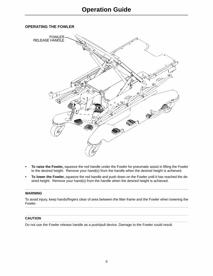
OPERATING THE FOWLER
� To raise the Fowler, squeeze the red handle under the Fowler for pneumatic assist in lifting the Fowlerto the desired height. Remove your hand(s) from the handle when the desired height is achieved.
� To lower the Fowler, squeeze the red handle and push down on the Fowler until it has reached the de-sired height. Remove your hand(s) from the handle when the desired height is achieved.
WARNING
To avoid injury, keep hands/fingers clear of area between the litter frame and the Fowler when lowering theFowler.
CAUTION
Do not use the Fowler release handle as a push/pull device. Damage to the Fowler could result.

Operation Guide
9
OPERATING THE FOOT SECTION
� To lower the foot section, with one hand, squeeze the foot section up/down release handle at the sideof the foot end of the litter. With the other hand, push down on the foot section to move it to the desiredangle.
� To raise the foot section, squeeze the foot section up/down release handle at the side of the foot endof the litter while holding the foot section to prevent it from rising too quickly.
WARNING
To avoid injury, keep hands/fingers clear of the area between the litter frame and the foot section when lower-ing the foot section.
Always hold the foot section when adjusting it. The foot section may rise too quickly and injury may result.
Do not sit on the foot section. Sitting on the foot section may result in a fall and injury. When the load on thefoot section exceeds 150 pounds, the foot section will lower to prevent the unit from tipping.

Operation Guide
10
OPERATING THE FOOT SECTION (CONTINUED)
� To remove the foot section for pelvic and lower body procedures, squeeze the red handles under thefoot section on both sides and lift the foot section from the two receptacles at the end of the seat.
� To mount the foot section, tilt the foot section and insert the two arms into the litter receptacles. Lowerthe foot section and verify it is locked securely in the receptacles.
WARNING
To avoid injury, always support the patient’s feet and legs before removing the foot section.
Do not sit on the foot section. Sitting on the foot section may result in a fall and injury. When the load on thefoot section exceeds 150 pounds, the foot section will lower to prevent the unit from tipping.
Operation Guide
11
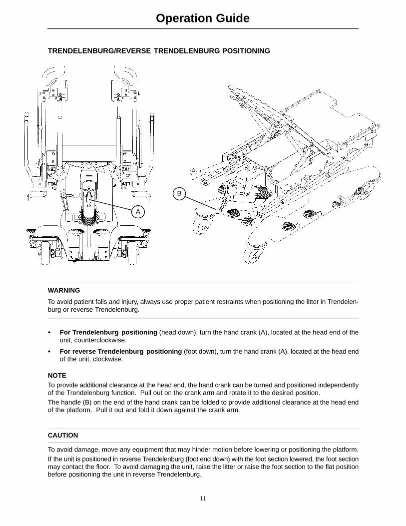
TRENDELENBURG/REVERSE TRENDELENBURG POSITIONING
A
B
WARNING
To avoid patient falls and injury, always use proper patient restraints when positioning the litter in Trendelen-burg or reverse Trendelenburg.
� For Trendelenburg positioning (head down), turn the hand crank (A), located at the head end of theunit, counterclockwise.
� For reverse Trendelenburg positioning (foot down), turn the hand crank (A), located at the head endof the unit, clockwise.
NOTETo provide additional clearance at the head end, the hand crank can be turned and positioned independentlyof the Trendelenburg function. Pull out on the crank arm and rotate it to the desired position.The handle (B) on the end of the hand crank can be folded to provide additional clearance at the head endof the platform. Pull it out and fold it down against the crank arm.
CAUTION
To avoid damage, move any equipment that may hinder motion before lowering or positioning the platform.If the unit is positioned in reverse Trendelenburg (foot end down) with the foot section lowered, the foot sectionmay contact the floor. To avoid damaging the unit, raise the litter or raise the foot section to the flat positionbefore positioning the unit in reverse Trendelenburg.
Operation Guide
12
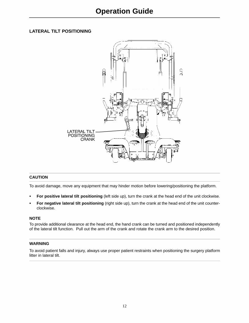
LATERAL TILT POSITIONING
CAUTION
To avoid damage, move any equipment that may hinder motion before lowering/positioning the platform.
� For positive lateral tilt positioning (left side up), turn the crank at the head end of the unit clockwise.
� For negative lateral tilt positioning (right side up), turn the crank at the head end of the unit counter-clockwise.
NOTETo provide additional clearance at the head end, the hand crank can be turned and positioned independentlyof the lateral tilt function. Pull out the arm of the crank and rotate the crank arm to the desired position.
WARNING
To avoid patient falls and injury, always use proper patient restraints when positioning the surgery platformlitter in lateral tilt.

Operation Guide
13
USING THE LITTER AND FOOT SECTION SIDERAILS (MODEL 1033 ONLY)
A
B
C
D
� To engage the litter siderails, pull up on the top rail (A) of the litter siderail and raise it to the full upposition until the latch engages with an audible click.
� To disengage the litter siderails, while holding the top rail, squeeze the red latch (B) on the litter andguide the siderail to the full down position.
� To engage the foot section siderails, pull up on the top rail of the foot siderail (C) and raise it to fullup position so the latch engages.
� To disengage the foot section siderails, while holding the top rail, pull the red latch (D) on the footsection toward the head end of the unit and guide the siderail to the full down position.
WARNINGTo avoid injury, be sure the siderail latching mechanisms are holding properly at all times.
When repositioning the siderails, grasp the top rail to avoid potential pinch points.
To avoid injury or damage to the equipment, do not allow the siderail to lower on its own.
When lowering the siderail to the collapsed position, keep extremities of patients and staff away from the side-rail spindles or injury could occur.

Operation Guide
14
USING THE SURGERY ACCESSORY RAILS
� Accessory rails border the litter frame. Direct clamps and other ancillary surgery equipment may be at-tached to the rails.
WARNING
To avoid patient injury or damage to the unit, remove equipment from the foot end accessory rail before chang-ing the position of the foot section and from the Fowler accessory rail before changing the position of the Fowler.

Operation Guide
15
USING THE IV POLE RECEPTACLES
� Two I.V. pole receptacles for use with standard I.V. poles are located at the head end of the unit on theFowler and at the foot end on the foot section.
WARNING
To avoid patient injury or damage to the unit, remove I.V. poles from the foot end receptacles before loweringthe foot section.

Operation Guide
16
OPERATING OPTIONAL FOOT END BACK REST
A
B
B
NOTEFor ease of installation and removal, keep the Foot End Back Rest horizontal while inserting or removing theguide posts from the receptacles.
To install the optional Foot End Back Rest, insert the two guide posts (A) into the receptacles on the litterfoot end. Be sure both sides of the back rest lock into place with an audible “click”.
To remove the Foot End Back Rest, rotate the levers (B) and pull the back rest away from the litter until theguide posts (A) are removed from the receptacles.
NOTEIf the unit is equipped with optional head extensions, remove them before removing the Foot End Back Rest(see page 18).
WARNINGDo not sit on the Foot End Back Rest. Excessive weight on the Foot End Back Rest could cause the unitto tip, resulting in injury.

Operation Guide
17
OPERATING OPTIONAL FOOT END BACK REST ARTICULATING HEAD PIECE
AXIS
AXIS
A
B
BOTTOM VIEW
Head Piece
Foot End Back Rest
To operate the articulating head piece, grasp either handle under the head section and squeeze. Handle (A)releases one latch and rotates the head piece on axis ”A”. Handle (B) releases the other latch and rotatesthe head section on axis ”B”. For ease of operation, it is recommended to release only one latch at a time.
WARNINGThe weight of the patient’s head is resting on the head piece and must be supported by the operator whenthe latches are released and the head piece is being positioned. Failure to adequately support the head piecewhile positioning the head could result in patient injury.To avoid possible pinch points when adjusting the head piece, keep your fingers away from the jointed areas.
Do not reach between the side of the head extension and the articulating head piece to pull the release handle.Finger injury could result.

Operation Guide
18
USING OPTIONAL FOOT END BACK REST PRE-OP/POST-OP HEAD EXTENSIONS
AB
C
BOTTOM VIEW
The Pre-Op/Post-Op Head Extensions are designed to be used only with the articulating head piece on theoptional Foot End Back Rest to provide additional litter surface and to protect the patient’s head during trans-port. The head extensions can be used as push handles when the Trio is being moved.
To insert the head extensions, pull the handle to retract the locking pin (B), insert the two pins (C) into thereceptacles on the Foot End Back Rest and release the handle so the locking pin clicks into place.
To remove the extensions from the litter, squeeze the handle (A) to retract the pin (B) on the side of the exten-sion frame and pull the extension assembly straight out from the litter.
NOTEHandle (A) only functions as a release lever for the head extension. It is not used for adjustment of the FootEnd Back Rest.

Operation Guide
19
OPERATING OPTIONAL FOOT END BACK REST CLAMP-ON SIDERAILS
A
A
NOTCH
B
RIGHT
LEFT
WARNING
The clamp-on siderails are only for use with the Foot End Back Rest. Do not use the clamp-on siderails onany accessory rail other than those on the seat section and do not use the clamp-on siderails with a standardfoot section or the siderail may not be secure and injury could occur.
Do not use the clamp-on siderails on opposite sides of the litter. They are designed to pivot in one directionand may not provide proper security if used on the wrong side.
To ensure proper security for the patient, after attaching the siderail, be sure to slide it all the way to the endof the accessory rail until it hits the stop (B) and won’t go any farther.
To attach the entire siderail assembly, turn the knob (A) fully counterclockwise to completely loosen it, movethe mattress aside, position the siderail assembly over the notches in the accessory rail, tilt it and pivot thesiderail onto the accessory rail.Slide the siderail along the accessory rail all the way to the end until it hits the stop (B) and won’t go any farther.Turn the knob (A) clockwise and tighten it securely to hold the siderail in place.
To use the clamp-on siderail, pivot it up and push it down until it locks into the receptacle. Pull the siderailup and pivot it down to store it.
To remove the entire siderail assembly, turn the knob (A) counterclockwise to loosen it, move the mattressaside, slide the siderail assembly to the notches in the accessory rail, tilt it and pivot it off the accessory rail.
CAUTION
Do not use the clamp-on siderails as push/pull devices or damage to the rails could occur.

Operation Guide
20
USING OPTIONAL CYSTO PAN
Tilt the cysto pan holder bracket (A) andinsert it between the top and bottom rollerbearings on the litter brackets.
Place the cysto pan (B) in the holderbracket.
The bracket and pan slide under the litter.Use the handle (C) to push them in or pullthem out.
A
A
B
C

Preventative Maintenance
21
CHECKLIST
All fasteners secure
Siderails move and latch properly (Model 1033 only)
Engage brake pedal and push on the stretcher to ensure all casters lock securely
Steer function works properly (Model 1033 only)
All casters secure and swivel properly
Body restraints work properly
I.V. pole intact and operates properly
Fowler operates properly
Foot section raises, lowers and latches properly
Trendelenburg/Reverse Trendelenburg operates properly
Lateral tilt operates properly
No rips or cracks in mattresses/Velcro attachments
Ground chain intact
No leaks at hydraulic connections
Hydraulic lift jack holds properly
Hydraulic Trendelenburg cylinder holds properly
Hydraulic drop rate set properly
Hydraulic oil level sufficient
Lubricate where required
Accessories and mounting hardware in good condition and work properly
Serial No.
Completed By:_________________________________ Date:_____________
NOTEPreventative maintenance should be performed at a minimum of annually. A preventative maintenance pro-gram should be established for all Stryker Medical equipment. Preventative maintenance may need to beperformed more frequently based on the usage level of the product.
Cleaning
22
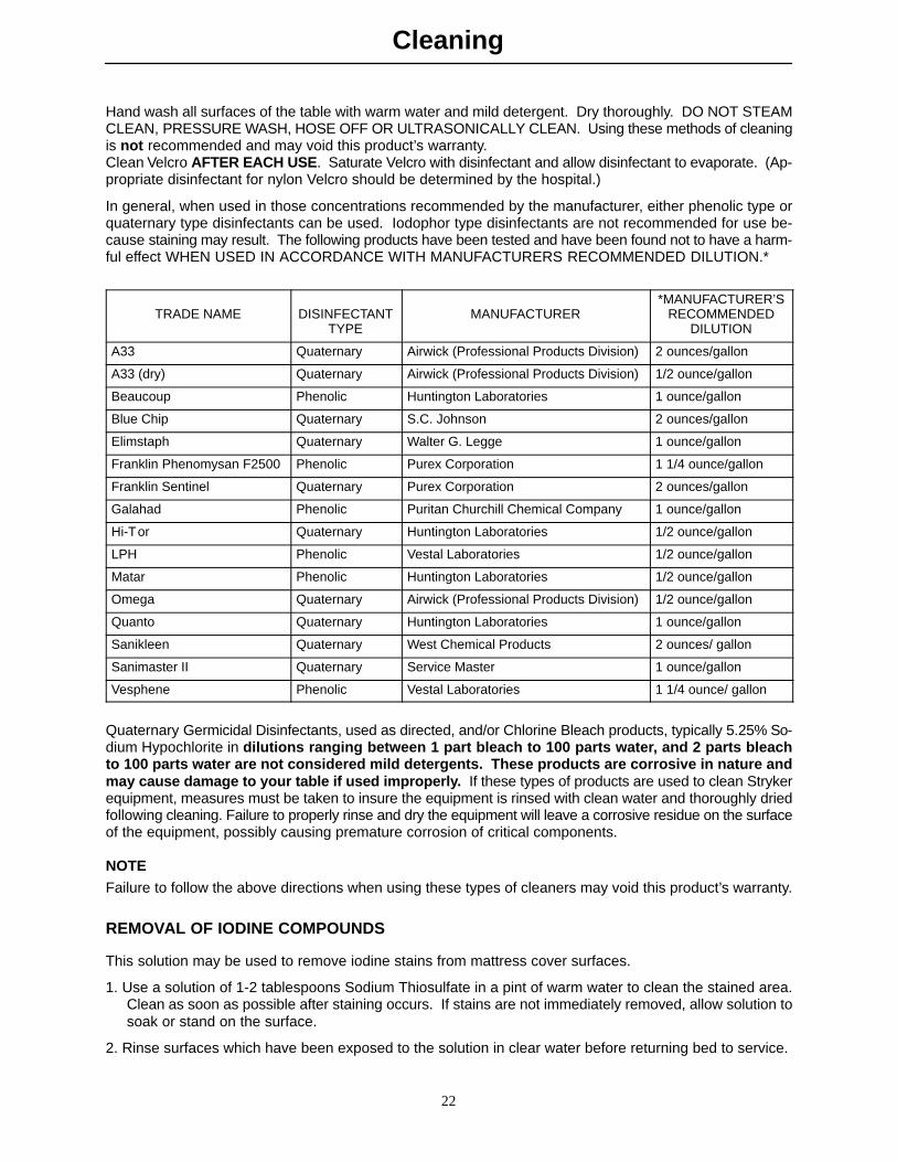
Hand wash all surfaces of the table with warm water and mild detergent. Dry thoroughly. DO NOT STEAMCLEAN, PRESSURE WASH, HOSE OFF OR ULTRASONICALLY CLEAN. Using these methods of cleaningis not recommended and may void this product’s warranty.Clean Velcro AFTER EACH USE. Saturate Velcro with disinfectant and allow disinfectant to evaporate. (Ap-propriate disinfectant for nylon Velcro should be determined by the hospital.)
In general, when used in those concentrations recommended by the manufacturer, either phenolic type orquaternary type disinfectants can be used. Iodophor type disinfectants are not recommended for use be-cause staining may result. The following products have been tested and have been found not to have a harm-ful effect WHEN USED IN ACCORDANCE WITH MANUFACTURERS RECOMMENDED DILUTION.*
TRADE NAME DISINFECTANTTYPE
MANUFACTURER*MANUFACTURER’S
RECOMMENDEDDILUTION
A33 Quaternary Airwick (Professional Products Division) 2 ounces/gallon
A33 (dry) Quaternary Airwick (Professional Products Division) 1/2 ounce/gallon
Beaucoup Phenolic Huntington Laboratories 1 ounce/gallon
Blue Chip Quaternary S.C. Johnson 2 ounces/gallon
Elimstaph Quaternary Walter G. Legge 1 ounce/gallon
Franklin Phenomysan F2500 Phenolic Purex Corporation 1 1/4 ounce/gallon
Franklin Sentinel Quaternary Purex Corporation 2 ounces/gallon
Galahad Phenolic Puritan Churchill Chemical Company 1 ounce/gallon
Hi-Tor Quaternary Huntington Laboratories 1/2 ounce/gallon
LPH Phenolic Vestal Laboratories 1/2 ounce/gallon
Matar Phenolic Huntington Laboratories 1/2 ounce/gallon
Omega Quaternary Airwick (Professional Products Division) 1/2 ounce/gallon
Quanto Quaternary Huntington Laboratories 1 ounce/gallon
Sanikleen Quaternary West Chemical Products 2 ounces/ gallon
Sanimaster II Quaternary Service Master 1 ounce/gallon
Vesphene Phenolic Vestal Laboratories 1 1/4 ounce/ gallon
Quaternary Germicidal Disinfectants, used as directed, and/or Chlorine Bleach products, typically 5.25% So-dium Hypochlorite in dilutions ranging between 1 part bleach to 100 parts water, and 2 parts bleachto 100 parts water are not considered mild detergents. These products are corrosive in nature andmay cause damage to your table if used improperly. If these types of products are used to clean Strykerequipment, measures must be taken to insure the equipment is rinsed with clean water and thoroughly driedfollowing cleaning. Failure to properly rinse and dry the equipment will leave a corrosive residue on the surfaceof the equipment, possibly causing premature corrosion of critical components.
NOTE
Failure to follow the above directions when using these types of cleaners may void this product’s warranty.
REMOVAL OF IODINE COMPOUNDS
This solution may be used to remove iodine stains from mattress cover surfaces.
1. Use a solution of 1-2 tablespoons Sodium Thiosulfate in a pint of warm water to clean the stained area.Clean as soon as possible after staining occurs. If stains are not immediately removed, allow solution tosoak or stand on the surface.
2. Rinse surfaces which have been exposed to the solution in clear water before returning bed to service.

Warranty
23
Limited Warranty:
Stryker Medical Division, a division of Stryker Corporation, warrants to the original purchaser that its productsshould be free from defects in material and workmanship for a period of one (1) year after date of delivery.Stryker ’s obligation under this warranty is expressly limited to supplying replacement parts and labor for, orreplacing, at its option, any product which is, in the sole discretion of Stryker, found to be defective. Strykerwarrants to the original purchaser that the frame and welds on its beds will be free from structural defectsfor as long as the original purchaser owns the bed. If requested by Stryker, products or parts for which awarranty claim is made shall be returned prepaid to Stryker’s factory. Any improper use or any alteration orrepair by others in such manner as in Stryker’s judgement affects the product materially and adversely shallvoid this warranty. Any repair of Stryker products using parts not provided or authorized by Stryker shall voidthis warranty. No employee or representative of Stryker is authorized to change this warranty in any way.
Stryker Medical stretchers are designed for a 10 year expected life under normal use conditions and appropri-ate periodic maintenance as described in the maintenance manual for each device.
This statement constitutes Stryker’s entire warranty with respect to the aforesaid equipment. STRYKERMAKES NO OTHER WARRANTY OR REPRESENTATION, EITHER EXPRESSED OR IMPLIED, EXCEPTAS SET FORTH HEREIN. THERE IS NO WARRANTY OF MERCHANTABILITY AND THERE ARE NOWARRANTIES OF FITNESS FOR ANY PARTICULAR PURPOSE. IN NO EVENT SHALL STRYKER BELIABLE HEREUNDER FOR INCIDENTAL OR CONSEQUENTIAL DAMAGES ARISING FROM OR IN ANYMANNER RELATED TO SALES OR USE OF ANY SUCH EQUIPMENT.
To Obtain Parts and Service:
Stryker products are supported by a nationwide network of dedicated Stryker Field Service Representatives.These representatives are factory trained, available locally, and carry a substantial spare parts inventory tominimize repair time. Simply call your local representative, or call Stryker Customer Service at (800)327-0770.
Service Contract Coverage:
Stryker has developed a comprehensive program of service contract options designed to keep your equip-ment operating at peak performance at the same time it eliminates unexpected costs. We recommend thatthese programs be activated before the expiration of the new product warranty to eliminate the potential ofadditional equipment upgrade charges.
A SERVICE CONTRACT HELPS TO:� Ensure equipment reliability
� Stabilize maintenance budgets
� Diminish downtime
� Establish documentation for JCAHO
� Increase product life
� Enhance trade-in value
� Address risk management and safety

Warranty
24
Stryker offers the following service contract programs:
SPECIFICATIONS GOLD SILVER PM* ONLY
Annually scheduled preventative maintenance X X
All parts,** labor, and travel X X
Unlimited emergency service calls X X
Priority one contact; two hour phone response X X X
Most repairs will be completed within 3 business days X X
JCAHO documentation X X X
On-site log book w/ preventative maintenance & emergency service records X
Factory-trained Stryker Service Technicians X X X
Stryker authorized parts X X X
End of year summary X
Stryker will perform all service during regular business hours (9-5) X X X
* Replacement parts and labor for products under PM contract will be discounted.** Does not include any disposable items, I.V. poles (except for Stryker HD permanent poles), mattresses, or damage re-
sulting from abuse.
Stryker Medical also offers personalized service contracts.
Pricing is determined by age, location, model and condition of product.
For more information on our service contracts, please call your local representative or call (800) 327-0770 (option #2).
Return Authorization:
Merchandise cannot be returned without approval from the Stryker Customer Service Department. An autho-rization number will be provided which must be printed on the returned merchandise. Stryker reserves theright to charge shipping and restocking fees on returned items.
SPECIAL, MODIFIED, OR DISCONTINUED ITEMS NOT SUBJECT TO RETURN.
Damaged Merchandise:
ICC Regulations require that claims for damaged merchandise must be made with the carrier within fifteen(15) days of receipt of merchandise. DO NOT ACCEPT DAMAGED SHIPMENTS UNLESS SUCH DAMAGEIS NOTED ON THE DELIVERY RECEIPT AT THE TIME OF RECEIPT. Upon prompt notification, Strykerwill file a freight claim with the appropriate carrier for damages incurred. Claim will be limited in amount tothe actual replacement cost. In the event that this information is not received by Stryker within the fifteen(15) day period following the delivery of the merchandise, or the damage was not noted on the delivery receiptat the time of receipt, the customer will be responsible for payment of the original invoice in full.
Claims for any short shipment must be made within thirty (30) days of invoice.
International Warranty Clause:
This warranty reflects U.S. domestic policy. Warranty outside the U.S. may vary by country. Please contactyour local Stryker Medical representative for additional information.
DH 2/03 1033-90-1 REV F
European Representative
Stryker France Phone: 33148632290BP 50040-95946 Roissy Ch. de Gaulle Fax: 33148632175Cedex-France
6300 Sprinkle Road, Kalamazoo, MI 49001-9799 (800) 327-0770www.strykermedical.com