Embed Size (px)
Citation preview

Mobile Solar Power Trailer
A Senior Project
Presented to
The Faculty of The Electrical Engineering Department
California Polytechnic State University, San Luis Obispo
In Partial Fulfillment
of the Requirements for the Degree
Bachelor of Science
by
Marisa Pummer, Jacob Salazar, & Benjamin Suminski
Advised by
Dale Dolan
June, 2021

1
Table of Contents
List of Tables .................................................................................................................................. 2
List of Figures ................................................................................................................................. 3
Abstract ........................................................................................................................................... 4
Introduction ..................................................................................................................................... 5
Background ..................................................................................................................................... 7
Customer Needs and Design Requirements .................................................................................. 10
Customer Needs ........................................................................................................................ 10
Design Requirements ................................................................................................................ 11
Functional Decomposition (Level 0 and Level 1) ........................................................................ 16
Level 0 Decomposition ............................................................................................................. 16
Level 1 Decomposition ............................................................................................................. 18
Results ........................................................................................................................................... 25
Specifications ............................................................................................................................ 25
Model ........................................................................................................................................ 26
Wiring Diagrams ....................................................................................................................... 28
Components and Costs .............................................................................................................. 32
Conclusion .................................................................................................................................... 35
References ..................................................................................................................................... 36
Appendices .................................................................................................................................... 39
APPENDIX A. (Senior Project Analysis) ................................................................................ 39

2
List of Tables
Table 1: Maximum Trailer Dimensions ........................................................................................ 11
Table 2: Example Construction Site Daily Power Consumption.................................................. 12
Table 3: Design Requirements ...................................................................................................... 15
Table 4: Level 0 Block Diagram Descriptions ............................................................................. 17
Table 5: Level 1 Block Diagram Descriptions ............................................................................. 19
Table 6: MST Specifications ........................................................................................................ 25
Table 7: DC Wire Sizes, Temperature Ratings, Ampacity Ratings, and Maximum Expected
Ampacity ....................................................................................................................................... 30
Table 8: AC Wire Sizes, Temperature Ratings, Ampacity Ratings, and Maximum Expected
Ampacity ....................................................................................................................................... 32
Table 9: MST Material and Component Costs ............................................................................. 33
3
List of Figures
Figure 1: Lifecycle Greenhouse Gas Emission of Electricity Generation Methods [8] ................. 7
Figure 2: Level 0 Block Diagram of the MST .............................................................................. 17
Figure 3: Level 1Block Diagram of the MST ............................................................................... 18
Figure 4: Fortess E-power 18.5 Lithium Battery [15] .................................................................. 20
Figure 5: FLEXpower Radian Inverter and MPPT [18] ............................................................... 22
Figure 6: WGen5300DF Portable Generator [19] ........................................................................ 23
Figure 7: Front View of the MST ................................................................................................ 26
Figure 8: Side View of the MST ................................................................................................... 27
Figure 9: Top View of the MST ................................................................................................... 27
Figure 10: Top View of the Inside of the MST ............................................................................ 28
Figure 11: MST DC Wiring Diagram ........................................................................................... 29
Figure 12: MST AC Wiring Diagram ........................................................................................... 31
Figure 13: Project Development Gantt Chart ............................................................................... 42
Figure 14: Profit Calculations ....................................................................................................... 45

4
Abstract
Construction projects require a substantial amount of power to operate tools and power
lights. Traditionally, this power is delivered to the project sites via transmission lines or
generators; however, some construction projects must be undertaken in relatively remote areas
where the infrastructure is lacking. Additionally, there may be reservations concerning the
ethical implications that come with the method by which the power is generated. To provide a
solution to bringing sufficient and ethically generated power to remote or urban worksites, this
project investigates the design and implementation of a generator that is solar-powered and
enclosed in a trailer for transportability. The Mobile Solar Power Trailer (MST) is a trailer
mounted with an array of PV panels that doubles as an enclosure for the supporting components
required for power generation, energy storage, DC-AC conversion, and the distribution required
to support a work site with reliable and adequate power. The scope of this project considers
aspects such as efficient use of sunlight, effective positioning of PV panels, adequate energy
storage, and appropriate scaling of components to deliver the required power. Cost estimates are
included for the final configuration and the overall design.

5
Introduction
Demand for solar power is predicted to take up about 47% of the market by 2050 [1].
There is also an ever-persistent demand for products that provide power during times of crises, in
remote areas, and that offset costs associated with traditional means of procuring power such as
generators or transmission lines [2]. Natural disasters such as floods, hurricanes, and earthquakes
can and do disrupt electrical distribution systems at varying levels of scale and severity every
single year [3]. Additionally, construction projects may be undertaken in areas that are lacking in
the infrastructure necessary to provide stable power. For example, a school or hospital may need
to be built in an indigenous community that lives off the grid. Another example could be a
facility such as a makeshift hospital that needs to be built in a remote area struck by illness or
war. These work sites will not have the luxury of transmitted power supplied by transmission
lines. Lastly, one may wish to minimize the use of fossil fuels and one's dependency on shore
power; both of which have monetary costs and contribute in varying degrees to the carbon
stock/flow in the environment. The Mobile Solar Power Trailer (MST) is a product designed for
the purpose of navigating and resolving the above-mentioned issues and more.
The MST integrates a charge controller, battery, bus work, an array of photovoltaic (PV)
panels, and fault protection to create a robust source of power that lasts for long periods of time
and supplies sufficient power for the load placed on it [5]. To maximize mobility and
accessibility, the MST is built in a mobile trailer to facilitate transportation to and from a site as
well as to provide simple protection from elemental exposure. The MST has AC outputs to
power various loads. The array of PV cells will convert sunlight into electricity. The power from
the PV cells either charges the onboard battery or is delivered to the load depending on the
system properties such as the State of Charge (SOC) of the battery, load demand, temp, etc [3].

6
The design of the trailer accounts for a plethora of design considerations such as the
power demand of construction sites, PV panel angles in relation to the sun, maximum
dimensions of the trailer, and many more design requirements. From the requirements and
considerations, components were chosen, and the trailer was modeled in Autodesk Inventor.
Further, calculations were performed to ensure the optimal wire sizes and protection was used in
the power system connections.
The design for the MST uses battery and inverter components that are modular and can
be scaled up in cases where more output power or energy storage is needed. Referring to the
appropriate datasheets, a modular design may be achieved and scaled accordingly to meet any
power demand [3-6]. Having modular components allows the system to be scaled up or down in
the future depending on the demand [7]. In this project, the customer will be referred to as a
potential buyer or user with the desire to find a power supply that meets the demands seen in the
Customer Needs and Design Requirements section.

7
Background
According to [7], the construction industry within the US spent $1,365,137 x $1,000,000
on construction in 2019. Due to the massive amounts of money flowing in the construction
industry, there is a large niche for supplying power to all the construction sites. As mentioned
before, construction sites typically get their power from grid interconnections, gas powered
generators or solar PV panels. Each method of supplying power has its unique drawbacks. These
drawbacks include environmental impacts and feasibility considerations (how easy is it to get
power to the site and cost).
When considering environmental impacts of supplying power to construction sites
greenhouse gas emissions can be used to compare the different methods of supplying power and
their impact on the environment. The greenhouse gas emissions of multiple generation sources
can be seen below in Figure 1.
Figure 1: Lifecycle Greenhouse Gas Emission of Electricity Generation Methods [8]

8
As seen in Figure 1 above, the CO2 emissions of coal, oil and solar PV are 888, 733, and
85 tonnes CO2e/GWh (CO2 emissions per GWh) respectively. Grid power is produced primarily
using coal, while generators used on construction sites use oil. Comparing the environmental
impact of each method of power generation in Figure 1, it can be seen that solar produces the
smallest amount of CO2 emissions. Oil has the second lowest CO2 emissions followed lastly by
coal. In terms of creating a more sustainable construction industry in the United States, solar PV
is the best of the three options.
Delivering power to construction sites can depend on location and the existing
infrastructure around the construction site. According to [9] installing a grid connection requires
the following:
1. Obtaining permits for creating connection and installing infrastructure
2. Engineering the design of the transmission system
3. Constructing the transmission system and installing a meter.
The setup of a grid connection can be expensive. Although the initial investment for a
grid connection may be pricey and time consuming, the power supplied by the grid connection is
reliable, regardless of time of day or weather conditions. If permits are unobtainable or
engineering and construction costs are too high for a project, other methods of power delivery
may be more viable.

9
Other options for supplying power include generators or a MST. These can be attached to
a vehicle and towed to a location. These mobile options require less time to obtain and set up at a
construction site. The downside of these mobile options are as follows:
• Generators require intermittent inputs such as diesel or gasoline to create power.
• PV panels do not produce power at night.
• PV output power is drastically reduced on cloudy days.
By combining a generator, solar PV panels, and a battery system into a single unit, the
power supply is both reliable and mobile. The costs associated with these mobile options include
the price of the unit and the price of the inputs.
An MST equipped with a generator and a battery system has the potential to provide
semi-clean energy to construction sites, while allowing for mobile deployment. Solar PV panels
provide clean energy, with the battery system and generator stepping in to provide power when
needed. By being situated on a trailer it can be easily moved and set up.

10
Customer Needs and Design Requirements
Customer Needs
While the issue of remote and renewable power generation exists in many variations, the
MST is specifically designed to meet the power demand for a construction site. By examining
the most common challenges encountered in terms of power generation for construction sites, we
can more directly identify and address those challenges which can be resolved by a product such
as the MST. The following customer needs were deemed as important to the scope of this
project:
1. Accessibility
o The trailer must be easily transportable for delivery to the customer and for easy
reorienting of the trailer to achieve the most efficient use of the solar panels.
2. Power
o The system must produce the power at a capacity determined by the customer.
o A battery backup must support irradiance conditions that do not allow maximum
power generation by solar means.
3. Environmental
o The MST must withstand continuous exposure to outdoor conditions such as rain,
snow, and extreme temperatures.
o The system must produce a relatively low amount of noise.

11
4. Efficiency
o The system must be an economically viable alternative such that other means of
power generation for construction sites will be more costly or equivalent in cost
compared to the MST.
o The solar array position must be adjustable to a degree that allows optimal
angling of the array to maximize solar power generation.
Design Requirements
The specifications are determined by addressing the needs outlined by the marketing
requirements. The MST must be mobile, so it must comply with all regulations on vehicle size
outlined in [10], [11], [12]. These dimensions are seen in Table 1 below.
Table 1: Maximum Trailer Dimensions
Maximum Dimension Length
Trailer Height [10] 13.5
Trailer Width [12] 8.5
Trailer Length [11] 38
These maximum dimensions are based on maximum semi-truck trailer dimensions for the state
of California.

12
The battery capacity requirement was determined by approximating the daily energy
consumption of a construction site. An example of the power used in a day on a construction site
can be seen in Table 2.
Table 2: Example Construction Site Daily Power Consumption
Tool Power Consumption
[kW]
No.
Tools
Hours Used
Per Day
Daily Power
Consumption [kWh]
Miter Saw 1.8 2 2.5 9
Compressor 1.6 2 2 6.4
Skill Saw 1.4 2 2.5 7
Table Saw 1.8 1 2.5 4.5
Battery
Charger
0.07 4 6 1.68
Work Lights 0.55 2 8 8.8
Total
37.38 kWh
The example construction site that uses the tools seen in Table 2 has a total daily power
consumption of 37.38 kWh. A depth of discharge (DoD) for the battery of 100% and a battery

13
voltage of 48Vdc was chosen. Using these assumptions / predictions the required battery
capacity was calculated to be about 37kWh or 771Ah with a terminal voltage of 48Vdc.
From the tools seen in Table 2 an approximation for the instantaneous power consumption
was determined. The following assumptions were made when calculating the instantaneous
power:
• Work Lights are always on.
• Battery Chargers are always charging.
• Only 4 tools are being used at any one time.
From these assumptions the maximum instantaneous power was calculated to be 8.38kW.
Therefore, the MST must be able to output about 8.38kW of power over long periods of time.
The charging time requirement for the battery system was determined to be 10 hours.
This time comes from the time between sunrise (7:08AM) and sunset (4:54PM) on the winter
solstice [13]. This time represents the minimum hours of sunlight the trailer must be able to
reach a full charge on when the panels are providing maximum power.
The battery lifetime specification was determined so the trailer would have a long
lifetime. The battery is one of the more expensive components of the trailer, so looking to design
the battery to have a long lifespan will help reduce future maintenance/replacement costs for the
battery system. The minimum battery life cycle was set at 2000 recharge/discharge cycles before
60% degradation. Assuming one recharge/discharge cycle per day, this requirement ensures that
the battery works adequately well for about five and a half years before it would need to be
replaced.

14
The noise dB specification was created by deciding how loud we wanted the machine to
be. At its maximum noise, the trailer should be no louder than an AC unit or 60dB (A-weighted
Measurement) with low and high frequencies filtered out to simulate the human ear [14].
The trailer will be used by a wide range of customers, who may not have any technical
electrical knowledge. To account for that the trailer should be easy to assemble/set up, and
should not take very long to do so. The setup time requirement was determined to be 5 minutes.
This will account for parking and securing the trailer, plugging in needed connections, and
turning the power output of the trailer on.
The enclosure housing the electrical equipment in the trailer should meet NEMA 3R,
which protects the equipment from falling rain, sleet, snow, and external ice formation. This
NEMA rating will ensure the safety of the electrical components while the trailer is outdoors.
Finally, the trailer must be able to output power at 120 volts and 240 volts. This requirement is a
result of the standard in the United States for common tools to be powered by 120/240 volts.

15
The design requirements are compiled in Table 3 below.
Table 3: Design Requirements
Requirement Value Units
Maximum Dimensions 38 x 8.5 x 13.5 Feet (LxWxH)
Min. Battery Capacity 37 kW-h
Continuous Power 8.38 kW
Maximum Charging Time From Solar Panels 10 Hours
Assembly Time 5 Minutes
Battery Lifetime 2000 cycles before 60%
Degradation
NA
Environmental Protection NEMA 3R NA
AC Output Voltage 120 / 240 Volts

16
Functional Decomposition (Level 0 and Level 1)
Level 0 Decomposition
The MST integrates multiple components to satisfy the customer needs outlined above. Very
generally, the system provides AC power for consumption at a typical construction site with
approximately 35Kw-h of demand. As shown in Figure 2 on the following page, the MST
generates AC power from sunlight or from a gasoline. Table 4 contains short descriptions of the
inputs and outputs seen in the level 0 block diagram.

17
Figure 2: Level 0 Block Diagram of the MST
Table 4: Level 0 Block Diagram Descriptions
INPUT / OUTPUT DESCRIPTION
SOLAR ENERGY INPUT Solar energy is captured and converted into electrical energy.
GASOLINE INPUT Gasoline is used to power the backup generator aboard the MST.
AC OUTPUT 120 / 240 Vac is delivered by the trailers output

18
Level 1 Decomposition
The level 1 Decomposition offers a more in depth look at the internal functions of the
MST. It includes all the major components that are included in the MST. The Level 1 block
diagram can be seen below in Figure 3. Table 5, following the level 1 block diagram, gives
descriptions for each input, output, and component.
Figure 3: Level 1Block Diagram of the MST

19
Table 5: Level 1 Block Diagram Descriptions
INPUT / OUTPUT/
COMPONENT
DESCRIPTION
SOLAR ENERGY
INPUT
Solar energy is captured and converted into electrical energy
GASOLINE INPUT Gasoline is used to power the backup generator aboard the MST
AC OUTPUT 120 / 240 Vac is delivered by the trailers output
CS3K-315 Solar
Panels
There are 16 solar panels atop the MST that convert sunlight to DC
current. Each Panel is rated to output 315W at full irradiance.
FLEXmax 100 MPPT The Maximum Power Point Tracker (MPPT) tracks the most efficient
point for varying solar conditions to output maximum power to the
inverter and battery.
GS8048 Inverter Takes in DC current from the MPPT or the Battery and converts the
current to AC current.
AC Load Panel Outputs AC power from the MST. Allows the user to connect their
tools to the 120 / 240 Vac output power.

20
Fortress E-Vault 18.5
Battery
Two 18.5 kWh batteries for a combined total of 37 kWh. Takes in
DC current from the MPPT
Wgen5300DF
Generator
Backup generator for the MST. Connects to the Inverter to supply
power to the user when the solar panels are not outputting power.
To achieve a 37kWh capacity, the MST utilizes two Fortress eVault 18.5kWh batteries,
which can be seen in Figure 4.
Figure 4: Fortess E-power 18.5 Lithium Battery [15]
Battery specifications were obtained from [15]. Each battery operates at a nominal voltage of
48V which matches our previously determined DC bus voltage. The two batteries will be placed
in parallel to maintain the nominal 48V DC bus and increases the electrical storage capacity to
the desired 37kWh. The parallel batteries also relieve stresses on each battery when under load

21
by sharing current supplied to the load; thus, preventing unnecessarily deep DoD when the
battery is not being charged. Due to lithium battery technology, the Fortress eVault batteries
have more life cycles, deeper DoD capability, and require no maintenance as opposed to lead-
acid technology. The lack of periodic maintenance, useful lifetime, and full utilization of label
plate capacity justifies the use of this battery despite it being the most expensive component of
the entire system.
To be able to fully charge the 37kWh battery within ten hours requires a solar panel array
with a production of about 3,700W. The MST solar array consists of sixteen CS3K-315MS solar
panels from Canadian Solar. According to [16] each panel is rated for 315 watts at full
irradiance. With 16 panels, the maximum solar output is 5,040W, which exceeds the required
3,700W. The solar panels have become significantly cheaper over the past few decades, and they
are the least expensive component in the MST. Due to their lower price, it is preferred to build as
large an array as possible to cut down costs for the other major components; however, available
space for the mounting of the panels is limited by the size of the trailer. With the limited
mounting space available, the panels are arranged in a 4S4P configuration. This arrangement
consists of four parallel strings of solar panels. Each string consists of four panels connected in
series.
The charge controller is the interface between the battery and the solar panels and its role
for the MST is fulfilled by a FLEXmax 100 AFCI. As seen in [17], the charge controller chosen
for this application is a 300V maximum power point tracker (MPPT) and functions as an
electronic buck converter that converts the incoming solar panel DC voltage down to a lower DC
voltage to charge the battery. The charge controller prevents overcharging of the battery and
optimizes charge current using maximum power point tracking. Various factors contributed to

22
choosing the specific charge controller. The FLEXmax 100 AFCI output voltage can match that
of the chosen battery voltage as well as provide the required charging current to the battery.
The inverter converts the DC that is generated and stored by the solar panels and battery,
respectively, into useful AC power. A Radian Series GS8048 was chosen for this application due
to its matching DC input voltage and sufficient output power. As seen in [18] it can output up to
8kW of continuous power. Additionally, the inverter and charge controller are provided in a
single package by the vendor. An image of this combination can be seen below in Figure 5. This
combination results in a lower overall cost and ensures the two components will integrate
seamlessly.
Figure 5: FLEXpower Radian Inverter and MPPT [18]

23
Fault protection is necessary to isolate a fault before catastrophic or irreparable damage is
inflicted upon the electrical system. Although the major components such as the battery, inverter,
and charge controller have their own safety features to protect from overvoltage, overcurrent,
and over temperature, among many other casualties, these features should not be solely relied
upon. Also, the safety features within each individual component may not necessarily be
designed to protect against the conditions that are present when the component in question is
integrated into an entire configuration. A DC quick disconnect is necessary to isolate the PV
array from the charge controller due to the PV array having no inherent means of dissipating a
charge or of deactivating the photovoltaic phenomena. Fault protection is also provided by a
Schneider Electric 50/51 Overcurrent relay, which prevents high current from damaging the
MST.
A Westinghouse dual fuel backup generator (Wgen5300DF) is included with the design
to compensate for extended periods of sunlight deficiency or to support vital electrical loads
when there is a fault upstream of the inverter. The generator can be seen in Figure 6.
Figure 6: WGen5300DF Portable Generator [19]

24
The dual fuel model takes gasoline and propane to flexibility to the user. The backup generator
also can provide 120- or 240-volt AC. As seen in [19], the Wgen5300DF is rated to for a
continuous output power of 5300 watts, therefore, it is capable of powering multiple tools at one
time.
To facilitate ease of transportation and set up, the electrical hardware is mounted on and
within a towable 28 by 8.5 by 7.62-foot trailer. The trailer is accompanied with wheels for the
purpose of transportation by road and has a widely used hitch connection to enable towing by
appropriately sized motor vehicles such as trucks. The enclosure is also sized in such a way that
shipping by freight trucks is not only possible but also complies with standards of transportation
and shipping.

25
Results
Specifications
The final specifications for the MST can be seen in Table 6 below.
Table 6: MST Specifications
Specification Value Units
Dimensions 28 x 8.5 x 7.62 Feet (LxWxH)
Battery Capacity 37 kWh
Continuous Output Power (Inverter) 8 kW
Continuous Output Power (Backup
Generator)
5.3 kW
Charging Time from Solar Panels @
Maximum Irradiance
7.4 Hours
Set Up Time 5 Minutes
Battery Lifetime 6000 cycles @ 98% DoD NA
Environmental Protection NEMA 3R NA
AC Output Voltage 120 / 240 Volts

26
Model
The MST and its main components were modeled in Autodesk Inventor. The model can
be seen in Figures 7 thru 10. The components modeled in the figures are the trailer, Fortress E-
Vault 18.5 battery, and a Radian Series GS8048 inverter.
Figure 7: Front View of the MST

27
Figure 8: Side View of the MST
Figure 9: Top View of the MST

28
Figure 10: Top View of the Inside of the MST
The MST has a width of 8.5 feet, a height of 7.6 feet and a length of 28 feet. Solar panels
are connected to hinges on the top and side of the MST, allowing for easy setup, changeable
panel angles, and safe travel. Inside the MST there is free space, not being used by components,
that can be repurposed for tool storage.
Wiring Diagrams
Using the expected currents in the different branches of the power system, wire sizes
were determined. Figure 6 shows the wiring diagram for the DC side of the power system. Table
7 shows the wire gauge for the wires seen in Figure 11 on the following page.

29
Figure 11: MST DC Wiring Diagram

30
Table 7: DC Wire Sizes, Temperature Ratings, Ampacity Ratings, and Maximum Expected Ampacity
Cable ID AWG T (°C) ating Ampacity Rating (A) Max Expected Ampacity (A)
DC1 8 90 55 40
DC2 8 90 55 40
DC3 12 90 30 NA
DC4 10 90 40 10
DC5 10 90 40 10
DC6 10 90 40 10
DC7 10 90 40 10
DC8 2/0 75 175 167
DC9 2/0 75 175 167
DC10 2/0 75 175 167
DC11 2/0 75 175 167
DC12 2 75 100 100
DC13 2 75 100 100
DC14 8 75 50 NA

31
Figure 12 shows the wiring diagram of the AC side of the MST power system. Table 8
provides the wire gauges for the wires seen in Figure 12.
Figure 12: MST AC Wiring Diagram

32
Table 8: AC Wire Sizes, Temperature Ratings, Ampacity Ratings, and Maximum Expected Ampacity
Cable ID AWG T (°C) Rating Ampacity Rating (A) Max Expected Ampacity (A)
AC1 8 75 50 46
AC2 8 75 50 46
AC3 6 75 65 67
AC4 6 75 65 67
AC5 8 75 50 68
AC6 8 75 50 67
AC7 12 75 25 NA
AC8 12 75 25 NA
Components and Costs
The MST is product made of many unique components. These components and their
approximate cost are shown in Table 9. The costs are then totaled to give an overall material cost
for the MST.

33
Table 9: MST Material and Component Costs
Component Quantity Cost ($) Supplier
CS3K-315 Solar Panels 16 2,848 A1 Solar Store
GS8048 FLEXpower Radian AFCI
Lite
1 7,500 Outback Solar
Fortress E-Vault 18.5 2 24,840 Northern Arizona Wind &
Sun
Westinghouse Wgen5300DF 1 615 Sam’s Club
Trailer 1 6,400 NA
12 AWG wire 56 feet 14 Wire & Cable Your Way
10 AWG wire 32 feet 12 Wire & Cable Your Way
8 AWG wire 158 feet 109 Wire & Cable Your Way
6 AWG wire 20 feet 21 Wire & Cable Your Way
2 AWG wire 8 feet 21 Wire & Cable Your Way
2/0 AWG wire 16 feet 70 Wire & Cable Your Way
Solar Racks 12 1,200 NA
Circuit Protection 1 400 Schneider Electric
Total 44,050
The total estimated cost of the MST, as seen in Table 9 is $44,050. For most components,
the costs were gathered from supplier data. For components such as the trailer and the solar
racks, a suitable price point was established using a weighted average of high price points, low

34
price points, and median price points. The equation used for the weighted average can be seen
below.
𝑊𝑒𝑖𝑔ℎ𝑡𝑒𝑑 𝐴𝑣𝑔 = 𝐿𝑜𝑤 𝑃𝑟𝑖𝑐𝑒 𝐸𝑠𝑡𝑖𝑚𝑎𝑡𝑒 + 𝐻𝑖𝑔ℎ 𝑃𝑟𝑖𝑐𝑒 𝐸𝑠𝑡𝑖𝑚𝑎𝑡𝑒 + 4(𝑀𝑒𝑑𝑖𝑎𝑛 𝑃𝑟𝑖𝑐𝑒 𝐸𝑠𝑡𝑖𝑚𝑎𝑡𝑒)
6

35
Conclusion
The MST encompasses a mobile source of solar generated power. It was designed to
provide power in remote areas that have no access to grid power. One such application is off grid
construction sites, but the MST could prove useful in other situations such as during or after
natural disasters or for people who are looking for a clean alternative power source. The design
of this trailer involved investigating the uses for the trailer, sizing the components, and creating a
3D model of the trailer. During the sizing of the trailer, an example construction site was used to
gauge the load that would be placed on the MST. Components were then chosen based on the
approximated load. Next, a design for the trailer and several of its major components were
created in Autodesk Inventor. Finally wire sizes and circuit protection devices were chosen for
the MST.
As a final product, the material cost of the MST is $44,050. It has a battery capacity of
37kWh, 5kW of solar, and an inverter capable of supplying 8kW of instantaneous power. As
seen in Appendix A, the MST will be produced for $45,450, which includes material and labor
costs. If produced on a commercial basis, where approximately 100 units are sold annually, the
MST will be sold for $50,000.

36
References
[1] “Annual Energy Outlook,” U.S. Energy Information Administration, 2021. Available:
https://www.eia.gov/outlooks/aeo/pdf/04%20AEO2021%20Electricity.pdf, (Accessed on:
June 3, 2021).
[2] S. Qazi, Photovoltaic Systems (PV) for Disaster Relief and Remote Areas, Amsterdam,
Netherlands: Elsevier, 2017. [Online]. Available:
https://www.elsevier.com/books/standalone-photovoltaic-pv-systems-for-disaster-relief-and-
remote-areas/qazi/978-0-12-803022-6
[3] “Major Power Outage Events,” Poweroutage.us. https://poweroutage.us/about/majorevents
(Accessed June 3,2021).
[4] H. Ritchie, “Electricity Mix” Ourworldindata.org. https://ourworldindata.org/electricity-
mix#:~:text=What%20is%20the%20breakdown%20of,electricity%20came%20from%20foss
il%20fuels (Accessed on: June 3, 2021).
[5] S. Krauter, “Solar Electric Power Generation - Photovoltaic Energy Systems,” Springer-
Verlag, Berlin, Germany, 2006. [Online]. Available: http://pvengineering.ir/wp-
content/uploads/Solar-Electric-Power-Generation-Photovoltaic-Energy-Systems.pdf
[6] https://www.mobilesolarpower.net/wp-content/uploads/2015/08/ms-solar-generator-
product.png
[7] “Annual Value of Construction Put in Place 2008 – 2019,” United States Census Bureau,
United States, 06-Oct-2020 [Online] Available:
https://www.census.gov/construction/c30/historical_data.html

37
[8] J. Mcintyre, B. Berg, H. Seto and S. Borchardt, “Comparison of Lifecycle Greenhouse Gas
Emissions of Various Electricity Generation Sources,” World Nuclear Association(WNA),
London, UK, July-2011. [Online]. Available: http://www.world-
nuclear.org/uploadedFiles/org/WNA/Publications/Working_Group_Reports/comparison_of_l
ifecycle.pdf
[9] “New or Upgraded Utility Service Connections (New Construction) Process Guide,” Pacific
Gas and Electric. [Online]. Available:
https://www.pge.com/includes/docs/pdfs/mybusiness/customerservice/startstop/newconstruct
ion/processguide/processguide.pdf
[10] “Height & Low Clearances,” Caltrans, California, United States, 2020 [Online].
Available: https://dot.ca.gov/programs/traffic-operations/legal-truck-
access/height#:~:text=Per%20the%20California%20Vehicle%20Code,a%20height%20of%
2014%20feet.&text=Any%20vehicle%20or%20load%20which,the%20entity%20operating
%20the%20bus
[11] “Vehicle Lengths,” Caltrans, California, United States, 2020 [Online].
Available: https://dot.ca.gov/programs/traffic-operations/legal-truck-access/vehicle-lengths
[12] “Vehicle Widths,” Caltrans, California, United States, 2020 [Online]. Available:
https://dot.ca.gov/programs/traffic-operations/legal-truck-access/vehicle-
widths#:~:text=General%20Rule,shall%20not%20exceed%20102%20inches.
[13] “December 2019 – San Luis Obispo, California – Sunrise and Sunset Calendar.” Sunrise-
Sunset.org. https://sunrise-sunset.org/us/san-luis-obispo-ca/2019/12 (Accessed June 4,
2021)

38
[14] A. Bhatia, “HVAC Systems Noise Control,” Continuing Education and Development, Inc,
Stony Point, NY
[15] Fortress Power, “eVault 18.5 Lithium Battery Storage.” Available:
https://www.fortresspower.com/wp-content/uploads/2021/03/newevault-brochure_final.pdf
[16] Canadian Solar, “KuPower High Efficiency Mono Perc Module CS3K-
315|320|325|330|335MS (1000V / 1500V),” May 2020. Available:
https://www.canadiansolar.com/wp-content/uploads/2020/05/Canadian_Solar-Datasheet-
KuPower_CS3K-MS_EN.pdf
[17] Outback Power, “FLEXmax 100 AFCI,” Aug. 2019. Available:
https://www.outbackpower.com/downloads/documents/charge_controllers/flexmax_100_afc
i/outback_082019_flexmax100afci_datasheet.pdf
[18] Outback Power, “FLEXpower Radian Fully Pre-Assembled 4 and 8kW Inverter Systems”,
July 2020. Available:
https://www.outbackpower.com/downloads/documents/integrated_systems/flexpower_radia
n/flexpowerradian_specsheet.pdf
[19] Westinghouse, “WGen5300DF Portable Generator” 2020. Available:
https://cdn.westinghouseoutdoorpower.com/owners_manuals/WGen5300DF_manual_web.p
df
[20] D. Kang, M. Chen and O. Ogunseitan, “Potential Environmental and Human Health Impacts
of Rechargeable Lithium Batteries in Electronic Waste,” in Environmental Science &
Technology, 2013. [Online]. Available: https://pubs-acs-
org.ezproxy.lib.calpoly.edu/doi/abs/10.1021/es400614y

39
Appendices
APPENDIX A. (Senior Project Analysis)
Project Title: Mobile Solar Trailer
Student’s Name: Ben Suminski Student’s Signature:
Student’s Name: Marisa Pummer Student’s Signature:
Student’s Name: Jacob Salazar Student’s Signature:
Advisor’s Name: Dale Dolan Date: 6/9/2021
1. Summary of Functional Requirements:
The MST delivers power to construction sites, temporary facilities, or other events. 5kW of Solar
Panels provide power when the sun is shining. Equipped with a 37 kWh battery system, the MST
delivers power even when there is no sun. With both power generation/storage, the MST offers
reliable power delivery. Because of its mobility, the MST is a great solution to delivering power
to remote construction sites and events.

40
2. Primary Constraints:
a. Number of PV Panels – Due to the size limitation of the MST the number of solar
panels that can be attached to the Trailer is limited. A clever design where solar
panels are mounted using hinges was used so panels could be mounted on the side of
the trailer as well as on the roof of the trailer. The panels can swivel on the hinges so
they can be angled towards the sun for maximum irradiance.
b. Trailer Size – Limited by road regulations and the uncertainty of which truck/car will
be used to tow the trailer. Different vehicles have different towing capacities.
3. Economic:
Economic impacts include:
a) There is the potential for increased profits for the construction industry. Construction
sites operate on marginal profits. The quicker they can complete projects, the greater the
return of profits. With a mobile source of power, less time is spent building infrastructure
to receive power and therefore less time and money is required.
b) Employment opportunities associated with production/maintenance of the MST will be
created. If manufactured, people would be employed to assemble the trailers and fix the
trailers if components broke or became degraded.
Costs accrue during the lifetime of the MST during the design, production, and maintenance of
the trailer. The benefits are returned during the sale and possibly the maintenance of the MST.
During the design of the MST, costs accrue through labor used to design the MST. During the
production of the MST, costs accrue from the purchase of components and materials used in the
trailer and labor costs associated with the production of the trailer. Further costs accrue when the

41
battery system, or PV panels degrade and need to be replaced. The cost of labor to replace these
components as well as the cost of the components are associated with the costs accrued. Benefits
accrue during the sale of the MST. The amount the trailer is sold for is the benefit.
Material cost estimates of the project resulted in an estimate of $44,050. In our case we are
students designing the project, so there are no design costs. The full project would entail design
costs, component costs, and production costs. Additional costs associated with the design of the
MST are the prices of the programs used to design the electrical system and the physical layout
of the trailer (Autodesk Inventor, Spice). As students we received these programs for free
through our institution. Other costs include equipment required to assemble the trailer as well as
lab equipment to test and verify the electrical components are performing as desired.
The project's profits can be seen in the Estimated Profit Per Year After Business Expenses
section. The final profit comes out to be $442,000.
The trailer’s lifetime is limited by the lifetime of the components. The most expensive
component of the MST is the battery system. Thus, the lifetime of the trailer will probably be
limited to the lifetime of the battery system. The battery, the Fortress Evault 18.5 is rated for
6000 cycles. Assuming one charge/discharge cycle per day, this battery would have a lifespan of
about 16 years.

42
The design of the trailer began the week of November 14th, 2020 and Designs were completed by
June 7th, 2021. The project development Gantt Chart can be seen below in Figure 13.
Figure 13: Project Development Gantt Chart
43
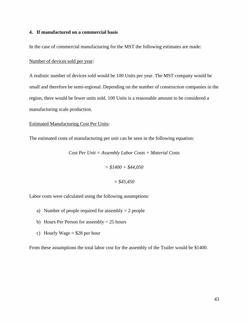
4. If manufactured on a commercial basis
In the case of commercial manufacturing for the MST the following estimates are made:
Number of devices sold per year:
A realistic number of devices sold would be 100 Units per year. The MST company would be
small and therefore be semi-regional. Depending on the number of construction companies in the
region, there would be fewer units sold. 100 Units is a reasonable amount to be considered a
manufacturing scale production.
Estimated Manufacturing Cost Per Units:
The estimated costs of manufacturing per unit can be seen in the following equation:
Cost Per Unit = Assembly Labor Costs + Material Costs
= $1400 + $44,050
= $45,450
Labor costs were calculated using the following assumptions:
a) Number of people required for assembly = 2 people
b) Hours Per Person for assembly = 25 hours
c) Hourly Wage = $28 per hour
From these assumptions the total labor cost for the assembly of the Trailer would be $1400.

44
Estimated Purchase Price Per Device:
The estimated purchase price per device is $50,000. This price would allow for a profit of $4,550
per unit sold. This profit would likely be smaller due to higher manufacturing prices as well as
marketing/sales costs.
Estimated Profit Per Year Before Business Expenses:
Based on 100 Units sold, for a profit of $4,550 per unit, the total estimated profit per year is
$455,000
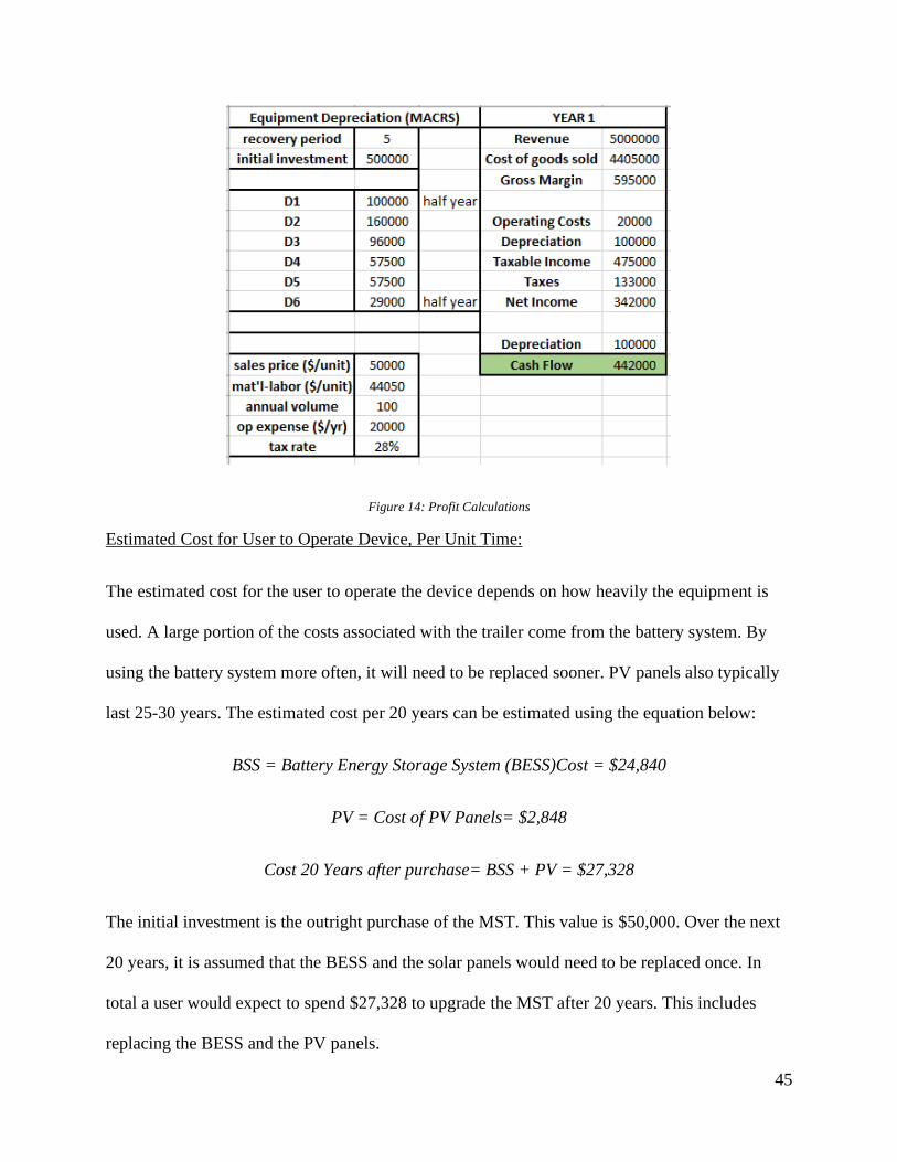
Estimated Profit Per Year After Business Expenses:
Operating costs such as rent, insurance, and utilities for the place of assembly were estimated to
be $20,000 a year. Certain large pieces of equipment would also be necessary for the successful
assembly and delivery of the MST. A crude estimate of $500,000 of equipment was used to
account for computers, office equipment, furniture, work truck, forklift, tools, etc. Depreciation
of the equipment was accounted for by using a five-year recovery period from the Modified
Accelerated Cost Recovery System (MACRS), which is the standard for tax statements.
Equipment depreciation can be written off and used as a tax cushion to lower taxable income.
Lastly, a estimated tax rate of 28% was used, although there state and local taxes, as well as
standard deduction like social security would also have to be considered for an actual business
plan. Assuming 100 units are sold in the first year, Figure 13 on the following page shows a
cashflow of $442,000 as profit. With the initial capital to buy the space and equipment to start
the business venture, the MST can be a successful and profitable endeavor. Depreciation greatly
helps in lowering the tax burden and scalability of production is a very viable option for growing
the business.
45
Figure 14: Profit Calculations
Estimated Cost for User to Operate Device, Per Unit Time:
The estimated cost for the user to operate the device depends on how heavily the equipment is
used. A large portion of the costs associated with the trailer come from the battery system. By
using the battery system more often, it will need to be replaced sooner. PV panels also typically
last 25-30 years. The estimated cost per 20 years can be estimated using the equation below:
BSS = Battery Energy Storage System (BESS)Cost = $24,840
PV = Cost of PV Panels= $2,848
Cost 20 Years after purchase= BSS + PV = $27,328
The initial investment is the outright purchase of the MST. This value is $50,000. Over the next
20 years, it is assumed that the BESS and the solar panels would need to be replaced once. In
total a user would expect to spend $27,328 to upgrade the MST after 20 years. This includes
replacing the BESS and the PV panels.

46
5. Environmental
The primary environmental concern for the MST is the disposal of the BESS. Batteries contain
heavy metals such as lead, cobalt, copper, and nickel [20], which, when mined, are damaging to
the environment as they require high amounts of water and create hazardous byproducts. They
also create a large amount of carbon emissions in the manufacturing process of the battery.
Batteries are not currently cost-effective to recycle, and so the proper steps should be taken when
disposing of the batteries.
The battery to be used for this application is of a Lithium-ion design. The Fortress eVault battery
was chosen for its superior performance and cost effectiveness. A Lithium based battery is
capable of deeper discharges, efficient rechargeability, higher power density, and has other
characteristics that made it the better choice. However, the process by which the lithium is
processed for consumption in the solar panel industry has significant environmental impacts that
are worth considering.
Lithium extraction uses approximately 500,000 gallons of water per ton of lithium and in some
areas, can use as much of 65% of the local areas water supply. Additionally, the most lithium
abundant areas of the world are particularly dry, which makes the process of procuring water
very expensive. Toxic chemicals are also involved in the evaporating and mining process. These
methods involving chemicals could introduces toxins back into the earth and have been known to
affect fish 150 miles downstream from a processing station. Some environmentalists would
consider lithium-ion technology to not be a viable solution at all and an informed consumer must
understand that a seemingly sustainable solution to a problem, such as powering a work site from
renewable sunlight, may not have a sustainable method of fabrication and assembly.

47
6. Manufacturability
Some possible manufacturing issues could arise in the following areas if larger scale
manufacturing were to take place:
a) Due to the size of the trailer, if the client purchasing the trailer is located far away from
the production site, shipping of the trailer may be an expensive component to be added on
to the manufacturing process.
b) Unless the process could be automated or made into a production line, orders could get
backed up if multiple trailers were ordered around the same time.
7. Sustainability
The MST utilizes PV panels, which uses a sustainable source to create power. The least
sustainable part of the MST is the BESS. The BESS may not be sustainable depending on the
chemicals/materials used within the batteries. Another aspect of sustainability associated with the
trailer is the metal used for framing and structural support. It must not be susceptible to rust and
must be cost effective. Research must be done to choose an appropriate material that provides
structural support, cost effectiveness, long life, and minimal contribution to net weight of the
system.
Upgrades to the BESS system such as better thermal and humidity control, as well as oversizing
would elongate the longevity of the BESS. This would make the lifespan of the trailer longer and
would reduce the environmental impact. Upgrading the BESS could prove to be financially
expensive and could drastically raise the price of the trailer.
8. Ethical

48
One ethical consequence associated with the MST, is the impact construction has on the
environment. When new buildings go up in areas of open land, habitats can be destroyed. By
being a mobile source of power, the MST enables construction sites to operate in areas of open
land. Without the MST, construction companies would likely use generators or connections to
the Grid to obtain power. In terms of carbon emissions, the MST is better than the alternatives,
but it still provides another way for construction sites to operate in areas where habitats may
exist. In terms of looking at the MST through the IEEE Code of Ethics, Code 5 “to improve the
understanding of technology, its appropriate application, and potential consequences;” the
project uses technology appropriately to do good. The technology in this case being the PV
panels and the BESS. These components allow renewable energy to be utilized in the
construction industry. This is an appropriate use of this technology.
An ethical framework to look at this product through is a utilitarian one. To maximize the good
for the greatest number of people, a product such as the MSPST can solve several power
concerns for those in various situations. The trailer can minimize reliance on grid power that may
be produced from unsustainable methods. Additionally, the trailer can provide much needed
electrical power in areas that do not have the infrastructure necessary to facilitate power demand
in remote or emergency areas. It must also be noted that the process by which batteries and solar
panels are produced is arguably detrimental to the environment. One could argue that the portion
of these potentially detrimental means of resource procurement that would go to the
manifestation of this trailer are small in comparison to the demand for these materials from other
ventures. However, as battery and photovoltaic technologies become of a higher demand over
time, one must consider whether it would be ethical to continue these harmful methods of

49
resource gathering until the market is saturated, at which point, the process by which these
resources are gathered would diminish in frequency.
9. Health and Safety
Health and Safety Concerns are as follows:
a) Electric Shock due to 120V – 240V outlets
b) Batteries and other conductive portions of the system can become serious electrical
hazards whether there is an electrical fault, or the system is operating under ideal
conditions. Any exposed conductive material must be visibly pointed out with signs or
partitioned off from inadvertent human contact. There must also be fault protection and
automatic circuit isolation to secure an electrical fault as close to the fault source as
possible to prevent unnecessarily isolating more of the system than is necessary and to
minimize damage to as many components in the system as possible.
c) Improperly secured materials may become loose in transit, especially on highways or
similar high-speed roads.
10. Social and Political
Social Issues that could arise with the use of the MST could be related to the level of education
people have on how the MST works. If people do not understand how the Trailer works, they
may not be able to utilize it to its full potential, or it could be dangerous for them to use. To
avoid this a detailed user manual could be provided to allow for all people to have a good
understanding of how the trailer works. Additionally, some individuals may have issues with the
origins of various components aboard the MST. The production of solar panels requires a lot of

50
water and toxic chemicals. Some of the byproducts of the production of such panels are also
toxic and hazardous if not handled correctly. There could also be social issues surrounding the
cars people have, with which they would tow the trailer. If people do not own a vehicle with a
towing capacity great enough to tow the trailer the trailer would be useless for them. This can be
remedied by providing a delivery service for the trailer whenever a customer desires to use it but
does not possess the means to transport it.
11. Development
Throughout the completion of this product, several excel sheets were developed to compare and
select components for the MST. Once components were selected, a basic 3D model was created
using Autodesk Inventor. To finish things off, excel sheets were used in calculating required wire
sizes for the power system in the MST.