Embed Size (px)
Citation preview

1 © Nokia 2016
Mobile Networks Evolution from LTE to 5G: Algorithms and Architecture
Rajeev AGRAWALRAN and Network Architecture & AlgorithmsMobile Networks CTO Office
(joint work with Anand Bedekar and Suresh Kalyanasundaram and several others)
Workshop on Information, Decisions, and Networks in honor of Demos TeneketzisUniversity of MichiganJuly 28, 2016

2 © Nokia 2016
• Drivers of Mobile Network Evolution and Key Enablers
• Spectrum - current and future
- Carrier aggregation, multi-connectivity
• Sites – current and future
- Small cells and eICIC
• Spectral Efficiency
- Coordinated Scheduling, CoMP
- Massive MIMO
- Other Spectral Efficiency techniques
• Cloud RAN
Outline

3 © Nokia 2016
Drivers for Network EvolutionExplosive growth in mobile traffic
• Smart phones/devices
- Open ecosystem of apps
- Social media
- Video
- Augmented/Virtual Reality
• Internet of Things
- Connected cars
- Smart cities/homes
- Verticals – health, industry
• 3.7 Exabtes per month in 2015• ~ 500 MB/month per person• ~ 1GB/month per unique sub

4 © Nokia 2015
Heterogeneous use-cases
10 yearson battery
100 Mbpswhenever needed
Ultrareliability
10-100x more devices
10 000x more traffic
M2Multra low cost
>10 Gbpspeak data rates
<1 msradio latency
Massivemachine
communication
ExtremeMobile
Broadband
Critical machine
communication
Three-pronged requirements for 5G networks

5 © Nokia 2015
Value, Capability & Cost Transformation for End User and Operator
Massively scale:Throughput/Capacity,
Latency, Resilience/Coverage, Quality of Experience
Distributed Cloud and NFV
New End User Services:Internet of Things,
Connected Cars,Verticals (Smart X)
Transport and SDNC
ap
ab
ility
& C
ost
T
ran
sfo
rma
tio
nV
alu
e
Tra
nsf
orm
ati
on
Scalable Core
AutomationProgrammability
Cognition

6 © Nokia 2016
Keys to Massively Scaling Throughput/Capacity
High density of cells
Small cells, Hetnet
High-capacity zones
Cell Splitting at Macro layer
Cell Density
Sub-6GHz to Cm/Mm Wave
Opportunistically exploit unlicensed spectrum
Aggregate all available spectrum – Carrier aggregation, multi-connectivity
High Peak Throughputs
Spectrum
Multi-cell coordination, interference cancellation
Massive MIMO
More efficient access to spectrum – Dynamic TDD etc
Spectral Efficiency
CentralizePoolingTransport
Centralized & Cloud RAN

7 © Nokia 2016
Keys to Massively Scaling Throughput/Capacity
High density of cells
Small cells, Hetnet
High-capacity zones
Cell Splitting at Macro layer
Cell Density
Sub-6GHz to Cm/Mm Wave
Opportunistically exploit unlicensed spectrum
Aggregate all available spectrum – Carrier aggregation, multi-connectivity
High Peak Throughputs
Spectrum
Multi-cell coordination, interference cancellation
Massive MIMO
More efficient access to spectrum – Dynamic TDD etc
Spectral Efficiency
CentralizePoolingTransport
Centralized & Cloud RAN

© 2016 Nokia8
Spectrum
ABI Research, 2016
Roughly consistent across many geographies –snapshot of APAC shown(ranges from 700MHz – 3.5GHz)
Up to 750MHz total already allocated
sub-3GHz: (450-700 MHz, 1.3-1.5, 2.7GHz)3-6GHz: (3.5-5, 5.9-6.4GHz)cm/mmWave: (28, 39, 65-75 GHz)
More spectrum will be made available
Licensing terms for new bands may be more constrained (e.g. shared spectrum, unlicensed)
Expensive, challenging terms, coverage constraints
BUT…

9 © Nokia Solutions and Networks 2014
Opportunistic use of unlicensed, shared-licensed, unreliable spectrum Complement reliable but limited licensed spectrumStarting in LTE (LAA, LWA, MulteFire), evolving into 5G
Spectrum
Unlicensed and Shared-licensed
Simultaneous use of multiple bandsHigher peak UE throughput, optimal load-balancingIntra- as well as inter-site
Carrier aggregation and Multi-connectivity
RAN Multi-connectivity anchor
Additional spectrum in Sub-6GHz bands, plus larger swaths in cm/mmWave bands
Sub-6GHz plus cm/mm-Wave
Cell sizeLOS/NLOS
Spectrum availability
300 MHz
3 GHz
30 GHz
10 GHz
90 GHz
10 cm
1m
cmWaveEnhanced urban
mmWaveUltra broadband
< 6GHzWide area
LOS
Confidential
LTE licensedCarrier Wi-Fi
LTE unlicensed
5GHz
Reliableconnection
Higher data ratesand more capacity
LWA LAA
LTE unlicensedor shared-
licensed
MulteFire
5GHz, 3.5GHz
High performance with neutral host

10 © Nokia Solutions and Networks 2014
Carrier Aggregation scenarios
F1 F2
F1 and F2 cells are co-located and overlaid, providing nearly the same coverage.
F1 and F2 cells are co-located and overlaid, but F2 has smaller coverage due to larger path loss.
F1 and F2 cells are co-located but F2 antennas are directed to the cell boundaries of F1 so that cell edge throughput is increased.
F1 provides macro coverage and on F2 RRHs are used to provide throughput at hot spots.

11 © Nokia 2016
• Joint scheduling for “Many groups of resources” arises in
- Carrier aggregation – multiple (possibly non-contiguous) bandwidth chunks
- Cell Selection or DL CoMP (DPS – Dynamic Point Selection) – multiple cells on same carrier frequency
- 5G – large contiguous bandwidth which can be viewed as union of smaller groups of resources
- Generically calling “a group of resources” = “a cell”
• Users may be eligible to be scheduled on all cells (for higher peak rates)
• Want to design “Jointly optimal scheduler” across all cells
• Scalability problem – complexity grows super-linearly with resources, number of users (e.g. max-max algorithm)
Scalable scheduling
… … …… Many groups of resources
“Jointly optimal scheduling”
... Many users, all eligible on all resources
Carrier 1
Carrier 2
Carrier n
…
Carrier Aggregation 5G
…
Cell 1 Cell 2
Cell 3
DL CoMP (DPS)

12 © Nokia Solutions and Networks 2014
Cell selection + user schedulingProblem formulation
• A user may be associated with more than one cell (within this localized set)- ρc,u – fraction of cell c’s resources given to user u
- ρc,u = 0 unless cell c is in coordination set of user u.
• User Throughput Tu = ∑c ρc,u Rc,u
• Utility maximization: - Decide allocations ρ*c,u to maximize ∑u U(∑c ρc,u Rc,u)
• Assumptions for simplifying problem – help to understand key principles- Assume channel is semi-static: stays constant long enough to reach optimal
allocations

13 © Nokia Solutions and Networks 2014
• Key result [specialized to U() = log() – extends to more general utility functions]:
• Optimality condition: Allocation rule ρ* is optimal iff for some cell-specific constants vc
Rc,u / T*u = vc if ρ*c,u > 0
≤ vc if ρ*c,u = 0
• Cell Metrics vc (“PF metric”) represent “load” in the cell
• At optimal, user gets non-zero allocation from “highest throughput cells”:
- Non-zero allocation from cell c only if Rc,u / vc ≥ Rd,u / vd for any other cell d
- Also handles case where user gets non-zero allocation from multiple cells
Cell selection + user scheduling (cont’d.)Optimality condition

14 © Nokia Solutions and Networks 2014
Relation between PF metrics vc and optimal allocations ρ*c,u:
• Let βc,u = fraction of user u’s throughput received from cell c
- βc,u = ρ*c,u Rc,u / [∑d ρ*d,u Rd,u]
• Result: vc = ∑u βc,u
• Interpretation:
- If all βs are 0 or 1 (each user receives allocations only from one cell), then
vc = Nc , number of users associated with cell c
- But in general βc,u can be a fraction –
- Then, cell c would treat user u as a fractional user with mass βc,u :
vc = “total mass” associated with cell c
• Result: For any two cells, at most one user “straddles” the two cells
Cell selection + user scheduling (cont’d.)Characteristics of optimal allocation

15 © Nokia Solutions and Networks 2014
• In practice, ρ*c,u within a cell for a given cell association can be found by a “scheduler”- Each cell’s scheduler implements the “gradient method” – in each slot,
schedules the user that currently has the highest gradient of the utility
- E.g. for U() = log(), gradient = Rc,u / Tu (Proportionally fair scheduler)
• Result (Agrawal, Subramanian 2002, Stolyar 2005): - Gradient-scheduler’s allocations converge to the optimal ρ*c,u
- User PF metrics in cell c converge to vc if scheduler allocates non-zero ρ*c,u
• Also works when a user is allowed to associate with multiple cells- In each time slot, user throughput Tu updated with allocations received in all
cells
Cell selection/association + user scheduling (cont’d.)Determining the optimal allocation ρ*c,u

16 © Nokia Solutions and Networks 2014
1. Each cell scheduler calculates vc (gradient scheduler - PF), for users currently assigned to it
- (Not shown) Cells exchange Tu of “straddling” users with other cells
2. Each cell (periodically) exchanges its vc with other cells
3. Decision at anchor cell – determine which user’s association to update, based on threshold rule
- Given current set of vc, “improve” a user u by allowing it to also receive resources from cell c*u that maximizes its estimated throughput Rc,u / vc
- If a user u gets ρ*c,u = 0 from some cell c, then remove that cell from its allocated set of cells
• Provable convergence to optimal under mild conditions
4. Notify chosen cells of user association changes
5. Each cell’s scheduler uses updated user association to schedule users and calculate its vc
Cell selection/association + user scheduling (cont’d.)Distributed Local Coord

17 © Nokia 2016
Scalable scheduling
… … …… Many groups of resources
“Jointly optimal scheduling”
... Many users, all eligible on all resources
Not scalable
… … ……
Per-cell Sch
... Many users, all eligible on all resources
Per-cell Sch Per-cell SchMore scalable
… … ……
Per-cell Sch
... Users mapped to groups of resources:Some users mapped to multiple groups
Per-cell Sch Per-cell SchEven more scalable
Joint scheduler decomposed into “cooperating per-cell Schedulers”

18 © Nokia 2016
Keys to Massively Scaling Throughput/Capacity
High density of cells
Small cells, Hetnet
High-capacity zones
Cell Splitting at Macro layer
Cell Density
Sub-6GHz to Cm/Mm Wave
Opportunistically exploit unlicensed spectrum
Aggregate all available spectrum – Carrier aggregation, multi-connectivity
High Peak Throughputs
Spectrum
Multi-cell coordination, interference cancellation
Massive MIMO
More efficient access to spectrum – Dynamic TDD etc
Spectral Efficiency
CentralizePoolingTransport
Centralized & Cloud RAN

© 2016 Nokia19
Cell Sites
Infonetics, 2015
Worldwide Macro Base Sites
• ~2000 subs/site• Global macro base sites growing at ~8-10% per year• Forecast for Small cells to grow even faster• New sites likely for capacity in high traffic areas than coverage
(already rolled out) – even more density increase there
Cell Density likely to increase significantly
• Cell-splitting, introduction of small cells will lead to greater interference
• Need to maximize spectral efficiency while combating interference
Interference is an increasing issue

20 © Nokia Solutions and Networks 2014
Very high density requires greater automationSub-optimal, highly irregular site locations greater need for automatic optimization (vs. manual planning)
Site Densification for Capacity – Small Cells
Automation for plug-and-play
Site splitting at wide-area level, + ultra-dense small cell clusters
High capacity zones
Coordination& control
Deployment & Set-up
Start & Diagnosis
Configuration change proposition
Configuration implementation
Verification
HetNet environment creates high interference scenariosCo-channel deployments lead to strong signal and interference
Inter-cell interference coordination

21 © Nokia 2016
• Co-channel HetNets – Macro causes strong interference to picos on same frequency
• Muting with “ABS” (almost blank subframes) – Macro mutes certain subframes so Pico users get better SINR –
- Pico users can report separate channel-state feedback for ABS and Non-ABS subframes
Dynamic eICIC: Adaptation of Muting
Macro
Pico
User u
a = ABS proportion
• Optimal muting: Given user assignments to macros and picos, and spectral efficiencies of users in ABS and Non-ABS subframes, determine ABS Muting Proportion a that macro should use
• Utility maximization formulation:
• Determine a, and resource allocation ρ to users in macro and pico, to
Maximize 𝑈 𝝆; 𝒂 = 𝑖𝑈𝑖 𝑇𝑖(𝝆; 𝒂)
• Utility function Ui(Ti) = log(Ti) leads to Proportional Fairness (PF)

22 © Nokia 2016
• Can view a pico cell as “two logical cells”, an ABS-cell and a non-ABS cell
- “ABS-cell” transmits when macro is muted (fraction a of the resources)
- “non-ABS cell” transmits when macro is not muted (fraction 1-a of the resources)
• Optimal resource allocation: Users partition into “ABS users” and “non-ABS users”
- Each user in a pico is in principle eligible for scheduling by both ABS-cell and non-ABS cell
- But (similar to “user mapping” earlier) – turns out that in the optimal resource allocation, users get mapped into either the ABS cell or the non-ABS cell – only a few users can get resources in both
• Optimal ABS proportion for log() utility: 𝑎∗ = 𝑐 𝑖𝑛 𝐴𝐵𝑆 𝑁𝑐 𝑐 𝑁𝑐
- Nc = number of user in cell c – so optimal ABS proportion = fraction of users who get resources in ABS
• Cell PF metric again plays an important role:
- vc = “Cell PF metric” of a cell = (for log() utility) “Number of users per unit resource” measure of load on a cell
• Nc / a for ABS cells or Nc / (1-a) for non-ABS cells
• For more general utilities, optimal ABS ratio in terms of “Generalized Cell PF metric”
- forms the basis of the criterion for mapping pico user to ABS or non-ABS
- Also forms the basis for determining optimal muting proportion
- Leads to iterative algorithm to achieve jointly optimal ABS proportion and optimal user assignment
Dynamic EICIC – Optimal Muting

23 © Nokia 2016
Keys to Massively Scaling Throughput/Capacity
High density of cells
Small cells, Hetnet
High-capacity zones
Cell Splitting at Macro layer
Cell Density
Sub-6GHz to Cm/Mm Wave
Opportunistically exploit unlicensed spectrum
Aggregate all available spectrum – Carrier aggregation, multi-connectivity
High Peak Throughputs
Spectrum
Multi-cell coordination, interference cancellation
Massive MIMO
More efficient access to spectrum – Dynamic TDD etc
Spectral Efficiency
CentralizePoolingTransport
Centralized & Cloud RAN

24 © Nokia Solutions and Networks 2014
Improving Spectral Efficiency
Higher efficiency with massive antenna arrays
Exploit active antennas, chip-scale massive antenna arrays
Massive MIMO 3D MIMO
Cell-edge performance in interference-limited scenarios
Key hooks being developed already in LTE, continue evolving into 5G
Multi-cell coordination
C2
C1
Cell Ci
Cell C2
Cell C1
Cell Ck
Cell C3 Benefit
Metric
Benefit
Metric
Benefit
Metric
Benefit
Metric
…
(1)
(2)
(8)
Column-1
16 TXRUs
Column-2
16 TXRUs
Column-3
16 TXRUs
Column-4
16 TXRUs
Better efficiency due to design of frame and control channelsFlexible control channel designFlexible TTI lengthsLower control overheadBetter packing of traffic with diverse types
Improved Numerology and Frame Structure
Enable more efficient multiple-access and duplexingBetween UL and DL –Dynamic TDD, Full DuplexAcross multiple users –NOMASeparate cell associations for UL, DL
More efficient channel access
and use

25 © Nokia 2016
• Consider muting (or lowering the power) of a cell
- Cell in question pays a penalty
- Neighbor cells benefit
- Consider Net Benefit and
• Mute if Net Benefit > 0
• Key Issues:
- Which cells should coordinate?
- Centralized or decentralized?
- What information should be shared?
- How often should it be shared?
• Do we need multiple iterations within a time-slot or is a single exchange adequate?
• Is there some kind of continuity across time-slots
- How do we combat latencies?
Multi-Cell Coordinated Scheduling
Cell Ci
Cell Ck
Cell Ck
Cell Cj
If Cell Ck mutes, Cell Cj benefits

26 © Nokia Solutions and Networks 2014
• Each cell influenced only by some set of neighboring cells
- Even if the totality of cells is large, only local influences
- Spectral efficiency of a user in a cell depends only on interference from a localized neighbor set
• Correspondingly, a cell’s “action” should be influenced only by the effect on a localized neighbor set
• Can we capitalize on this localized-influence structure in solving global optimization?
- Can global optimal be reached by making decisions with only local awareness confined to cell-specific cluster?
- Can it be reached by distributed decision making – each cell makes decisions based on some (parsimonious) awareness of state of localized neighbors?
Method of update may be sequential (one cell at a time) or parallel (all cells together) or in-between (some subset of cells update in parallel – e.g. “independent sets”)
Localized Structure
1
2
Cell-
specific
Cluster
of Cell 1
Cell-
specific
Cluster
of Cell 2

27 © Nokia Solutions and Networks 2014
• The cell-specific clusters are overlapping – in general effects of one cell’s action may have ripple effects propagating outside that cell-specific cluster
• In general, some centralized/global-view optimization may be needed- However, such solutions do not scale well, and have single-point-of-failure issues
• So would like to have decentralized algorithms, where actions are taken in a distributed way at each cell
• A cell may coordinate with other cells (message passing) – but ideally confine coordination to the per-cell local cluster
• May require possibly multiple iterations of message passing – either multiple per slot (TTI), or spread out over multiple TTIs
• Want to identify insights from theory that allow design of decentralized mechanisms
Localized structure (cont’d.)

28 © Nokia Solutions and Networks 2014
• Assuming R = log (1+SINR), any limit point of the power sequence for Sequential or Partially parallel using independent sets satisfies:
• For linearized (interference price) or full functional form of interference penalty- Value function improves at each step
- Limit point satisfies KKT conditions• Follows from Shi, Honig, Berry for linearized form
- But not necessarily convergence to global optimum – can’t prove uniqueness of optimal
• In addition for the full functional form - Limit point is also optimal in any one dimension
Sequential or Partially parallel using independent setsKey results
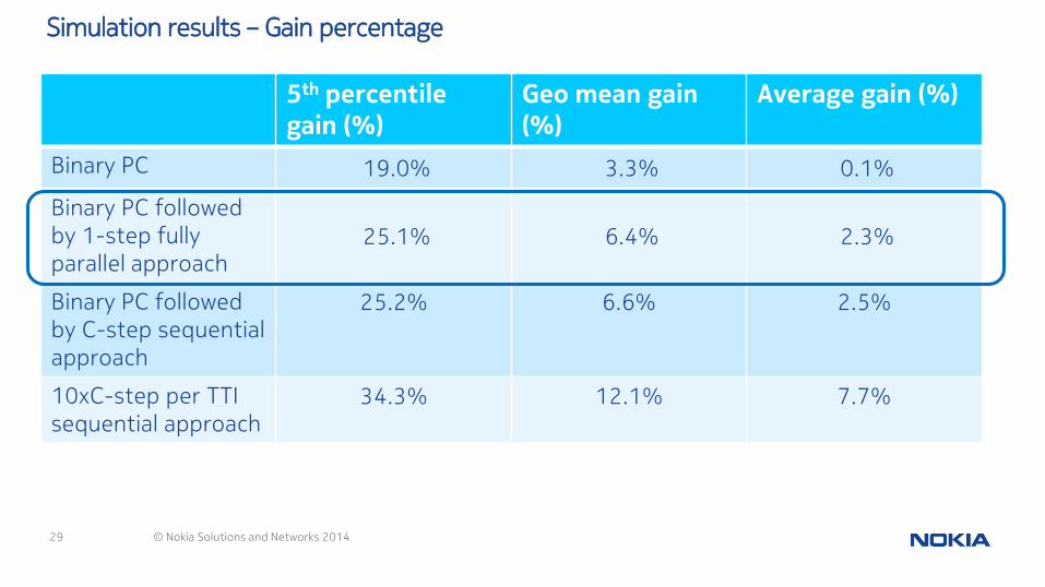
29 © Nokia Solutions and Networks 2014
Simulation results – Gain percentage
5th percentile gain (%)
Geo mean gain (%)
Average gain (%)
Binary PC 19.0% 3.3% 0.1%
Binary PC followed by 1-step fully parallel approach
25.1% 6.4% 2.3%
Binary PC followed by C-step sequential approach
25.2% 6.6% 2.5%
10xC-step per TTI sequential approach
34.3% 12.1% 7.7%

30 © Nokia Solutions and Networks 2014
Multi-cell coordination benefits from fast inter-connect …. but can still provide gains over non-ideal inter-connects
Algorithm DL/UL Interconnectrequirements between Cell BBs
<< 1 msec 5 ms > 10 ms
Dynamic eICIC DL Signaling
Inter-site CA DL User data
Coordinated Scheduler DL Signaling
DPS CoMP DL User data
JR CoMP UL I/Q data
Full Gains Partial Gains No Gains
Multi-Cell Coordination
C1
C2
Cell Ci
Cell C2
Cell C1
Cell Ck
Cell C3
B(C1; Hi)
B(C2; Hi)
B(C3; Hi)
…
Framework described also applicable to Coordinated Beamforming

31 © Nokia Solutions and Networks 2015
Massive MIMOFor wide area (<6 GHz) as well as high (cm/mm-wave) bands
At high bands: Massive antenna arrays to overcome propagation challenges
Beamforming at RF
Polarization 2 stream MIMO
Chip-scale array elements
Active antennas
Vertical sectorization
UE-specific beamforming
<1 ms
GHz2,9 GHz2 + 0,9 GHz BW
70-85
38
90-95
< 6
28 2 GHz150/852 MHz BW
10 GHz5 GHz BW
4 GHz50 MHz BW
Spectrum availability
≥ 16 element arrays at base station

32 © Nokia 2016
PHY/RF problems:
• Beam space design: What is the set of beams in consideration? Is there any structure to the beam space?
- Common/cell-specific + selection + UE specific
- In BB or RF (phase shifts) or hybrid
- Discrete (e.g. hierarchical/multi-level or other grid-of-beams) or continuous (based on UL pilots/data) set
• Pilot design & Channel estimation: How are the common/cell-specific beams chosen? How is the UE–specific beam chosen?
- Do we have channel reciprocity (TDD)?
- UL pilots/data
- DL pilots and UE feedback
- Some combination of the two
Scheduling, Resource Allocation, RRM problems:
• Pilot management: How often to use which pilot?
- Trade-off between learning and optimization
• Beam scheduling:
- How often to schedule which beam?
- How often to schedule a set of beams (with potential overlaps)
- CQI/PMI/RI estimation for UE (based on beam choice and other beams active)
- Resource allocation problem – similar to resource allocation in eICIC/ABS
• Mapping users to beams
- Similar to cell selection problem
• Power control - Power on different beams
- Similar to coordinated cell muting/power control problem
Massive MIMO3D (2D planar array), RF domain BF (in addition to BB domain), Antennas >> BB streams

33 © Nokia 2016
Keys to Massively Scaling Throughput/Capacity
High density of cells
Small cells, Hetnet
High-capacity zones
Cell Splitting at Macro layer
Cell Density
Sub-6GHz to Cm/Mm Wave
Opportunistically exploit unlicensed spectrum
Aggregate all available spectrum – Carrier aggregation, multi-connectivity
High Peak Throughputs
Spectrum
Multi-cell coordination, interference cancellation
Massive MIMO
More efficient access to spectrum – Dynamic TDD etc
Spectral Efficiency
Multi-cell coordinationPoolingTransport
Centralized & Cloud RAN

34 © Nokia 2015
Centralized/Cloud RAN configurations
BBU
Back-haul to EPC
BBU
Fiber-CPRI/OBSAI
Fiber-CPRI/OBSAI
BBU
Back-haul to EPC
BBU
Conventional Macro
Macro including RRHs
BBU
Fronthaul(typically dark fiber)
BBU
Fiber-CPRI/OBSAI
Fiber-CPRI/OBSAI
Centralized RAN
Central SiteAka BBU Hotel(e.g. CO)
Back-haul to EPC
X-haul
(partly) virtualized, pooled BBUs
Fiber orEthernet
Fiber or Ethernet
Cloud RAN
Central Site(e.g. CO)
Back-haul to EPC
Some BB fns
Some BB fns
LocalRH
RemoteRH
LocalRH
RemoteRH
Fiber-CPRI/OBSAI
Fiber-CPRI/OBSAI
• Baseband functions may be split between central site and cell site
• Aim to support packetized X-haul• Some of the centralized BB functions
may be virtualized on GPP servers• Pooling of processing across cells• Cloud techniques for automation and
orchestration

35 © Nokia 2016
Cloud RAN – Challenges and Solutions
• Disaggregate SW architecture for maximizing pooling benefits
• Load-based elastic scaling
• Enhanced Orchestration and Virtualized Infrastructure Management for RAN
• Common algorithm architecture for distributed and centralized
• Exploit per-cell Clusters
• Enable time-sensitive functions on GPP (x86, ARM)
• Some functions may still be on non-GPP hw
• Different functional splits and algorithm enhancements matched to transport needs
• Improve transport networks
• Co-locating RAN across cells and with EPC enables latency optimizations
RAN software optimized for Cloud operation
Cloud Management
Multi-cell coordination
Maximize use of server platforms
Enable Ethernet Fronthaul
Optimization of latencies

36 © Nokia 2015
To Centralize or Not to CentralizeCoordination, Pooling, Costs
Sch
L1
Sch
L1
Inter-site nbr
MAC
RLC
PDCP
RLC
PDCP
MAC
RRCRRC
Distributed Coordination: Instantaneous intra-site nbr info, delayed inter-site nbr info
Sch
L1
Sch
L1
RLC
PDCP
MAC
RRCRRC
RLC
PDCP
MAC
Fronthaul
Intra-cloudCoordination
Instantaneous nbr info, but delayed fronthaul
Pooled Functions
Coordination affected by Latency, BW of interconnect and fronthaul
Distributed vs Centralized Coordination
Site costs in distributed network vs fronthaul costs in centralized
Centralization for cost reduction
Efficient deployment of massive processing resources – pooling across cells (esp for per-user functions)
Maximize pooling gains

37 © Nokia 2015
• Traffic growth and new end user services such as IoT are driving mobile network evolution
• Spectrum additions across different bands including licensed, unlicensed and lightly licensed
• Site densification primarily using small cells/hetnets
• Algorithms to combat new challenges due to spectrum addition, site densification and interference management are needed –
- these all require multi-cell optimization - decentralized algorithms offer scalable solutions
• Massive MIMO offers an important dimension to improve spectral efficiency
• Several other spectral efficiency improvement techniques are also being considered
• Cloud RAN offers a potential disruptive solution to scale baseband compute requirements cost effectively and also offer operators the ability to experiment with new algorithms and features
- Functionality may get moved around with latency and throughput constraints on the interconnect network
• Algorithm and architecture design are central to mobile network evolution
Summary

38
RAN and Network Architecture & AlgorithmsWhat we do
Cloud RAN
Multi-Cell Coordination
massiveMIMOAlgorithmsSimulations Architecture
88
LTE–Advanced-Pro
5G
Radio Access Technologies
Scheduler, RRM
Receiver, Channel Est.
Algorithms
eNB(PHY, MAC),
Network
RAN & Network
Proof-of-Concept

39 © Nokia Solutions and Networks 2014
Happy 65th Birthday Demos!
Confidential

40 © Nokia 2015


![Evolving Mobile Networks - John Wiley & Sonscatalogimages.wiley.com/images/db/pdf/0470853220.excerpt.pdf · Evolving Mobile Networks ... Ericsson puts it [4], ... The global evolution](https://img.dokumen.tips/doc/110x75/5a7ddb087f8b9a49588ded0b/evolving-mobile-networks-john-wiley-mobile-networks-ericsson-puts-it-4.jpg)


