Embed Size (px)
Citation preview

Mobile InternetWireless Network Architectures and Applications
Sridhar IyerK R School of Information Technology
IIT Bombay
[email protected]://www.it.iitb.ac.in/~sri

Sridhar Iyer IIT Bombay 2
Outline
Introduction and Overview Wireless LANs: IEEE 802.11 Mobile IP routing TCP over wireless GSM air interface GPRS network architecture Wireless application protocol Mobile agents Mobile ad hoc networks

Sridhar Iyer IIT Bombay 3
References J. Schiller, “Mobile Communications”, Addison Wesley, 2000 802.11 Wireless LAN, IEEE standards, www.ieee.org Mobile IP, RFC 2002, RFC 334, www.ietf.org TCP over wireless, RFC 3150, RFC 3155, RFC 3449 A. Mehrotra, “GSM System Engineering”, Artech House, 1997 Bettstetter, Vogel and Eberspacher, “GPRS: Architecture, Protocols
and Air Interface”, IEEE Communications Survey 1999, 3(3). M.v.d. Heijden, M. Taylor. “Understanding WAP”, Artech House, 2000 Mobile Ad hoc networks, RFC 2501
Others websites:– www.palowireless.com– www.gsmworld.com; www.wapforum.org– www.etsi.org; www.3gtoday.com

Sridhar Iyer IIT Bombay 4
Wireless networks
Access computing/communication services, on the move
Cellular Networks– traditional base station infrastructure systems
Wireless LANs– infrastructure as well as adhoc networks possible– very flexible within the reception area– low bandwidth compared to wired networks (110 Mbit/s)
Ad hoc Networks– useful when infrastructure not available, impractical, or expensive– military applications, rescue, home networking
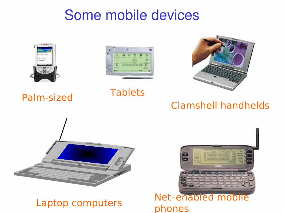
Some mobile devices
Clamshell handhelds Tablets
Net–enabled mobile phones
Palm-sized
Laptop computers

Sridhar Iyer IIT Bombay 6
Limitations of the mobile environment• Limitations of the Wireless Network
• limited communication bandwidth • frequent disconnections• heterogeneity of fragmented networks
• Limitations Imposed by Mobility• route breakages• lack of mobility awareness by system/applications
• Limitations of the Mobile Device• short battery lifetime• limited capacities

Sridhar Iyer IIT Bombay 7
Wireless v/s Wired networks Regulations of frequencies
– Limited availability, coordination is required– useful frequencies are almost all occupied
Bandwidth and delays– Low transmission rates
• few Kbits/s to some Mbit/s.– Higher delays
• several hundred milliseconds– Higher loss rates
• susceptible to interference, e.g., engines, lightning
Always shared medium– Lower security, simpler active attacking– radio interface accessible for everyone– Fake base stations can attract calls from mobile phones– secure access mechanisms important

Sridhar Iyer IIT Bombay 8
Cellular systems: Basic idea
Single hop wireless connectivity– Space divided into cells– A base station is responsible to communicate with
hosts in its cell– Mobile hosts can change cells while communicating– Handoff occurs when a mobile host starts
communicating via a new base station
Factors for determining cell size– No. of users to be supported– Multiplexing and transmission technologies
Sridhar Iyer IIT Bombay 9
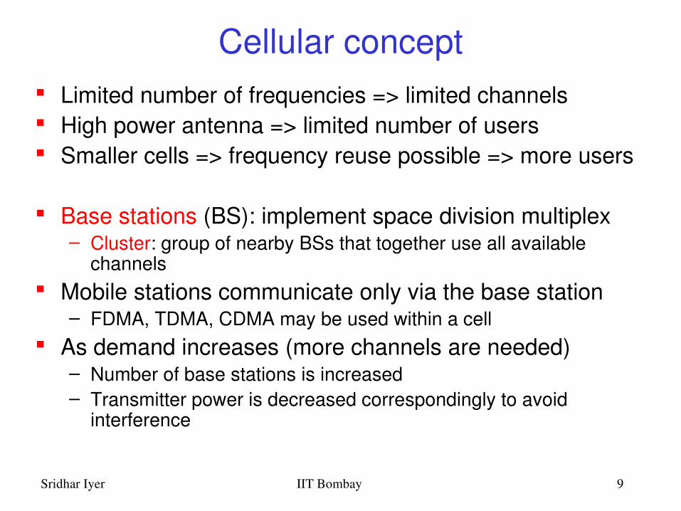
Cellular concept Limited number of frequencies => limited channels High power antenna => limited number of users Smaller cells => frequency reuse possible => more users
Base stations (BS): implement space division multiplex– Cluster: group of nearby BSs that together use all available
channels Mobile stations communicate only via the base station
– FDMA, TDMA, CDMA may be used within a cell As demand increases (more channels are needed)
– Number of base stations is increased– Transmitter power is decreased correspondingly to avoid
interference

Sridhar Iyer IIT Bombay 10
Cellular system architecture
Each cell is served by a base station (BS) Each BSS is connected to a mobile switching center (MSC)
through fixed links Each MSC is connected to other MSCs and PSTN
MSC MSC
HLR
VLR
HLR
VLR
To otherMSCs
PSTNPSTN

Sridhar Iyer IIT Bombay 11
Outgoing call setup
Outgoing call setup:– User keys in the number and presses send– Mobile transmits access request on uplink signaling
channel– If network can process the call, BS sends a channel
allocation message– Network proceeds to setup the connection
Network activity:– MSC determines current location of target mobile
using HLR, VLR and by communicating with other MSCs
– Source MSC initiates a call setup message to MSC covering target area

Sridhar Iyer IIT Bombay 12
Incoming call setup
Incoming call setup:– Target MSC (covering current location of mobile)
initiates a paging message– BSs forward the paging message on downlink
channel in coverage area– If mobile is on (monitoring the signaling channel), it
responds to BS– BS sends a channel allocation message and informs
MSC Network activity:
– Network completes the two halves of the connection

Sridhar Iyer IIT Bombay 13
HandOffs BS initiated:
– Handoff occurs if signal level of mobile falls below threshold– Increases load on BS
• Monitor signal level of each mobile• Determine target BS for handoff
Mobile assisted:– Each BS periodically transmits beacon– Mobile, on hearing stronger beacon from a new BS, initiates
the handoff
Intersystem:– Mobile moves across areas controlled by different MSC’s– Handled similar to mobile assisted case with additional
HLR/VLR effort
Sridhar Iyer IIT Bombay 14
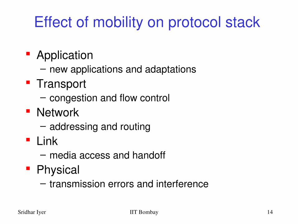
Effect of mobility on protocol stack
Application– new applications and adaptations
Transport– congestion and flow control
Network– addressing and routing
Link– media access and handoff
Physical– transmission errors and interference

Sridhar Iyer IIT Bombay 15
Mobile applications 1
Vehicles– transmission of news, road condition etc– adhoc network with near vehicles to prevent
accidents
Emergencies– early transmission of patient data to the hospital– adhoc network in case of earthquakes, cyclones– military ...

Sridhar Iyer IIT Bombay 16
Mobile applications 2
Travelling salesmen– direct access to central customer files– consistent databases for all agents
Web access– outdoor Internet access – intelligent travel guide with uptodate
location dependent information
Location aware services– find services in the local environment

Sridhar Iyer IIT Bombay 17
Mobile applications 3
Information services– push: e.g., stock quotes– pull: e.g., weather update
Disconnected operations– mobile agents, e.g., shopping
Entertainment– adhoc networks for multi user games
Messaging

Sridhar Iyer IIT Bombay 18
Mobile applications in the Industry
Wireless access: (phone.com) openwave Alerting services: myalert.com Location services: (airflash) webraska.com Intranet applications: (imedeon) viryanet.com Banking services: macalla.com Mobile agents: tryllian.com ….

19IIT BombaySridhar Iyer
Bandwidth and applications
Speed, kbps
2GCDMA 2.5G
GPRS, CDMA 2000EDGEUMTS
Transaction ProcessingMessaging/Text Apps
Voice/SMSLocation Services
Still Image TransfersInternet/VPN Access
Database AccessDocument TransferLow Quality Video
High Quality Video
9.6 14.4 28 64 144 384 2000
Sridhar Iyer IIT Bombay 20
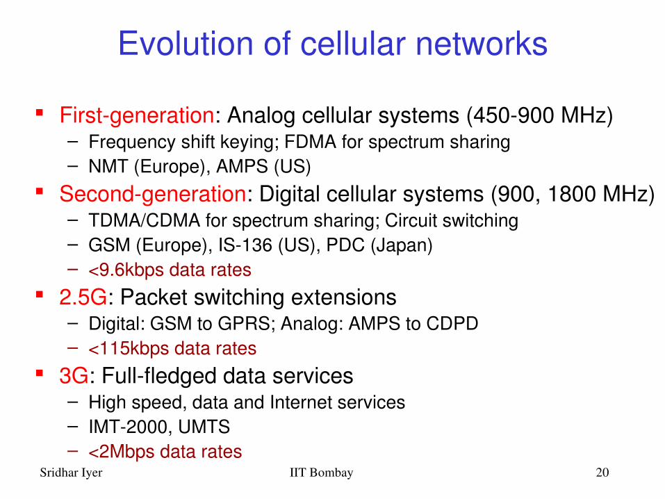
Evolution of cellular networks
Firstgeneration: Analog cellular systems (450900 MHz)– Frequency shift keying; FDMA for spectrum sharing– NMT (Europe), AMPS (US)
Secondgeneration: Digital cellular systems (900, 1800 MHz)– TDMA/CDMA for spectrum sharing; Circuit switching– GSM (Europe), IS136 (US), PDC (Japan)– <9.6kbps data rates
2.5G: Packet switching extensions– Digital: GSM to GPRS; Analog: AMPS to CDPD– <115kbps data rates
3G: Fullfledged data services– High speed, data and Internet services– IMT2000, UMTS– <2Mbps data rates

Sridhar Iyer IIT Bombay 21
GSM to GPRS
Radio resources are allocated for only one or a few packets at a time, so GPRS enables– many users to share radio resources, and allow
efficient transport of packets– connectivity to external packet data networks– volumebased charging
High data rates (up to 171 kbps in ideal case) GPRS carries SMS in data channels rather than
signaling channels as in GSM
Sridhar Iyer IIT Bombay 22
UMTS: Universal Mobile Telecomm. Standard
Global seamless operation in multicell environment (SAT, macro, micro, pico)
Global roaming: multimode, multiband, lowcost terminal, portable services & QoS
High data rates at different mobile speeds: 144kbps at vehicular speed (80km/h), 384 kbps at pedestrian speed, and 2Mbps indoor (office/home)
Multimedia interface to the internet Based on core GSM, conforms to IMT2000 WCDMA as the airinterface

Sridhar Iyer IIT Bombay 23
Evolution to 3G Technologies
IS95BCDMA
2G 3G
cdma2000
GSMFDD
TDD
WCDMA
GPRS
IS136TDMA UWC136
EDGE & 136HS outdoor
136 HSindoor

Sridhar Iyer IIT Bombay 24
384 Kbps
56 Kbps
54 Mbps
72 Mbps
511 Mbps
12 Mbps 802.11
Wireless Technology Landscape
Bluetooth
802.11b
802.11{a,b}Turbo .11a
Indoor
10 – 30m
IS95, GSM, CDMA
WCDMA, CDMA2000
Outdoor
50 – 200m
Mid rangeoutdoor
200m – 4Km
Long rangeoutdoor
5Km – 20Km
Long distance com.
20m – 50Km
µwave ptop links
.11 ptop link
2G
3G

Sridhar Iyer IIT Bombay 25
3G Network Architecture
Mobile AccessRouter
WirelessAccess Network
IPBase Stations
Gateway
Telephone Network
Core Network
User Profiles &Authentication
(HLR)
3G AirInterface
Wired Access
802.11
IP Intranet
IP Intranet
ProgrammableSoftswitch
ApplicationServer
802.11
Access Point
Access Point
Internet

Sridhar Iyer IIT Bombay 26
Wireless LANs
Infrared (IrDA) or radio links (Wavelan) Advantages
– very flexible within the reception area – Adhoc networks possible– (almost) no wiring difficulties
Disadvantages– low bandwidth compared to wired networks– many proprietary solutions
Infrastructure v/s adhoc networks (802.11)

Sridhar Iyer IIT Bombay 27
Infrastructure vs. Adhoc Networksinfrastructure network
adhoc network
APAP
AP
wired network
AP: Access Point
Source: Schiller

Sridhar Iyer IIT Bombay 28
Difference Between Wired and Wireless
If both A and C sense the channel to be idle at the same time, they send at the same time.
Collision can be detected at sender in Ethernet. Halfduplex radios in wireless cannot detect collision
at sender.
A B CA
B
C
Ethernet LAN Wireless LAN

Sridhar Iyer IIT Bombay 29
– A and C cannot hear each other.– A sends to B, C cannot receive A. – C wants to send to B, C senses a “free” medium
(CS fails)– Collision occurs at B.– A cannot receive the collision (CD fails).– A is “hidden” for C.
Hidden Terminal Problem
BA C

Sridhar Iyer IIT Bombay 30
IEEE 802.11
Acknowledgements for reliability Signaling packets for collision avoidance
– RTS (request to send) – CTS (clear to send)
Signaling (RTS/CTS) packets contain– sender address– receiver address– duration (packet size + ACK)
Powersave mode

Sridhar Iyer IIT Bombay 31
Spectrum War: Status todayEnterprise 802.11Network
Public 802.11Wireless Carrier
Source: Pravin Bhagwat

Sridhar Iyer IIT Bombay 32
Spectrum War: EvolutionEnterprise 802.11Network
Public 802.11Wireless Carrier
Market consolidation Entry of Wireless
Carriers Entry of new players Footprint growth
Source: Pravin Bhagwat

Sridhar Iyer IIT Bombay 33
Spectrum War: Steady StateEnterprise 802.11Network
Public 802.11Wireless Carrier
Virtual Carrier
Emergence of virtual carriers
Roaming agreements
Source: Pravin Bhagwat

Sridhar Iyer IIT Bombay 34
Routing and Mobility
Finding a path from a source to a destination Issues
– Frequent route changes– Route changes may be related to host movement– Low bandwidth links
Goal of routing protocols– decrease routingrelated overhead– find short routes– find “stable” routes (despite mobility)

Sridhar Iyer IIT Bombay 35
Mobile IP: Basic Idea
Router1
Router3
Router2
S MN
Home agent
Source: Vaidya

Sridhar Iyer IIT Bombay 36
Mobile IP: Basic Idea
Router1
Router3
Router2
S MN
Home agent
Foreign agent
move
Packets are tunneledusing IP in IP
Source: Vaidya
Sridhar Iyer IIT Bombay 37
TCP over wireless
TCP provides– reliable ordered delivery (uses retransmissions, if
necessary)– cumulative ACKs (an ACK acknowledges all
contiguously received data)– duplicate ACKs (whenever an outoforder segment is
received) – endtoend semantics (receiver sends ACK after data
has reached)– implements congestion avoidance and control using
congestion window
Sridhar Iyer IIT Bombay 38
TCP over wireless
Factors affecting TCP over wireless:– Wireless transmission errors
• may cause fast retransmit, which results in reduction in congestion window size
• reducing congestion window in response to errors is unnecessary
– Multihop routes on shared wireless medium• Longer connections are at a disadvantage compared to
shorter ones, because they have to contend for wireless access at each hop
– Route failures due to mobility

Sridhar Iyer IIT Bombay 39
Indirect TCP (ITCP)
ITCP splits the TCP connection– no changes to the TCP protocol for wired hosts– TCP connection is split at the foreign agent – hosts in wired network do not notice
characteristics of wireless part– no real endtoend connection any longer
mobile hostaccess point (foreign agent) „wired“ Internet
„wireless“ TCP standard TCP
Source: Schiller

Sridhar Iyer IIT Bombay 40
Mobile TCP (MTCP)
Handling of lengthy or frequent disconnections MTCP splits as ITCP does
– unmodified TCP for fixed network to foreign agent– optimized TCP for FA to MH
Foreign Agent– monitors all packets, if disconnection detected
• set sender window size to 0• sender automatically goes into persistent mode
– no caching, no retransmission

Sridhar Iyer IIT Bombay 41
Application Adaptations for Mobility
• Design Issues• System transparent v/s System aware• Application transparent v/s Application aware
• Models• conventional, “unaware” client/server model• client/proxy/server model• caching/prefetching model• mobile agent model

Sridhar Iyer IIT Bombay 42
World Wide Web and Mobility
HTTP characteristics– designed for large bandwidth, low delay– stateless, client/server, request/response
communication– connection oriented, one connection per request– TCP 3way handshake, DNS lookup overheads
HTML characteristics– designed for computers with “high” performance,
color highresolution display, mouse, hard disk– typically, web pages optimized for design, not for
communication; ignore endsystem characteristics

Sridhar Iyer IIT Bombay 43
System Support for Mobile WWW
Enhanced browsers– clientaware support for mobility
Proxies– Client proxy: prefetching, caching, offline use– Network proxy: adaptive content transformation
for connections – Client and network proxy
Enhanced servers– serveraware support for mobility– serve the content in multiple ways, depending on
client capabilities New protocols/languages
– WAP/WML

Sridhar Iyer IIT Bombay 44
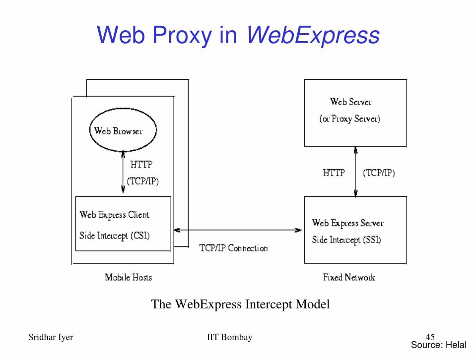
The Client/Proxy/Server Model
Proxy functions as a client to the fixed network server
Proxy functions as a mobilityaware server to mobile client
Proxy may be placed in the mobile host (Coda), or the fixed network, or both (WebExpress)
Enables thin client design for resourcepoor mobile devices
Sridhar Iyer IIT Bombay 45
Web Proxy in WebExpress
The WebExpress Intercept Model
Source: Helal

Sridhar Iyer IIT Bombay 46
Wireless Application Protocol
Browser– “Micro browser”, similar to existing web browsers
Script language– Similar to Javascript, adapted to mobile devices
Gateway– Transition from wireless to wired world
Server– “Wap/Origin server”, similar to existing web servers
Protocol layers– Transport layer, security layer, session layer etc.
Telephony application interface– Access to telephony functions

Sridhar Iyer IIT Bombay 47
WAP: Network Elements
wireless networkfixed network
WAPproxy
WTAserver
filter/WAPproxyweb
server
filter
PSTN
Internet
Binary WML: binary file format for clients
Binary WML
Binary WML
Binary WML
HTML
HTML
HTML WML
WMLHTML
Source: Schiller
Sridhar Iyer IIT Bombay 48
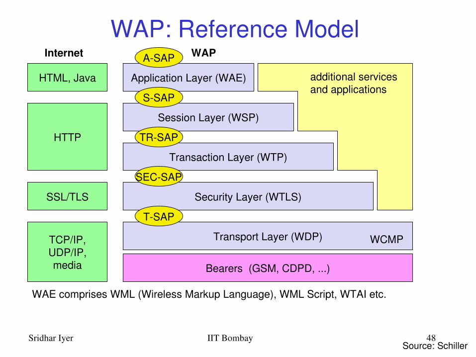
WAP: Reference Model
Bearers (GSM, CDPD, ...)
Security Layer (WTLS)
Session Layer (WSP)
Application Layer (WAE)
Transport Layer (WDP)TCP/IP,UDP/IP,media
SSL/TLS
HTML, Java
HTTP
Internet WAP
WAE comprises WML (Wireless Markup Language), WML Script, WTAI etc.
Source: Schiller
Transaction Layer (WTP)
additional services and applications
WCMP
ASAP
SSAP
TRSAP
SECSAP
TSAP

Sridhar Iyer IIT Bombay 49
WAP Stack Overview WDP
– functionality similar to UDP in IP networks
WTLS– functionality similar to SSL/TLS (optimized for wireless)
WTP– Class 0: analogous to UDP– Class 1: analogous to TCP (without connection setup overheads)– Class 2: analogous to RPC (optimized for wireless)– features of “user acknowledgement”, “hold on”
WSP– WSP/B: analogous to http 1.1 (add features of suspend/resume)– method: analogous to RPC/RMI– features of asynchronous invocations, push (confirmed/unconfirmed)

Sridhar Iyer IIT Bombay 50
The Mobile Agent Model
Mobile agent receives client request and Mobile agent moves into fixed network
Mobile agent acts as a client to the server Mobile agent performs transformations and filtering
Mobile agent returns back to mobile platform, when the client is connected

Sridhar Iyer IIT Bombay 51
Mobile Agents: Example

Sridhar Iyer IIT Bombay 52
Outline
Introduction and Overview Wireless LANs: IEEE 802.11 Mobile IP routing TCP over wireless GSM air interface GPRS network architecture Wireless application protocol Mobile agents Mobile ad hoc networks

Sridhar Iyer IIT Bombay 53
How Wireless LANs are different
Destination address does not equal destination location
The media impact the design– wireless LANs intended to cover reasonable
geographic distances must be built from basic coverage blocks
Impact of handling mobile (and portable) stations– Propagation effects – Mobility management– power management

Sridhar Iyer IIT Bombay 54
Wireless Media
Physical layers in wireless networks– Use a medium that has neither absolute nor readily
observable boundaries outside which stations are unable to receive frames
– Are unprotected from outside signals– Communicate over a medium significantly less reliable than
wired PHYs– Have dynamic topologies– Lack full connectivity and therefore the assumption normally
made that every station (STA) can hear every other STA in invalid (I.e., STAs may be “hidden” from each other)
– Have time varying and asymmetric propagation properties

Sridhar Iyer IIT Bombay 55
802.11: Motivation
Can we apply media access methods from fixed networks Example CSMA/CD
– Carrier Sense Multiple Access with Collision Detection– send as soon as the medium is free, listen into the medium if a
collision occurs (original method in IEEE 802.3)
Medium access problems in wireless networks– signal strength decreases proportional to the square of the
distance– sender would apply CS and CD, but the collisions happen at the
receiver– sender may not “hear” the collision, i.e., CD does not work– CS might not work, e.g. if a terminal is “hidden”
Hidden and exposed terminals
Sridhar Iyer IIT Bombay 56
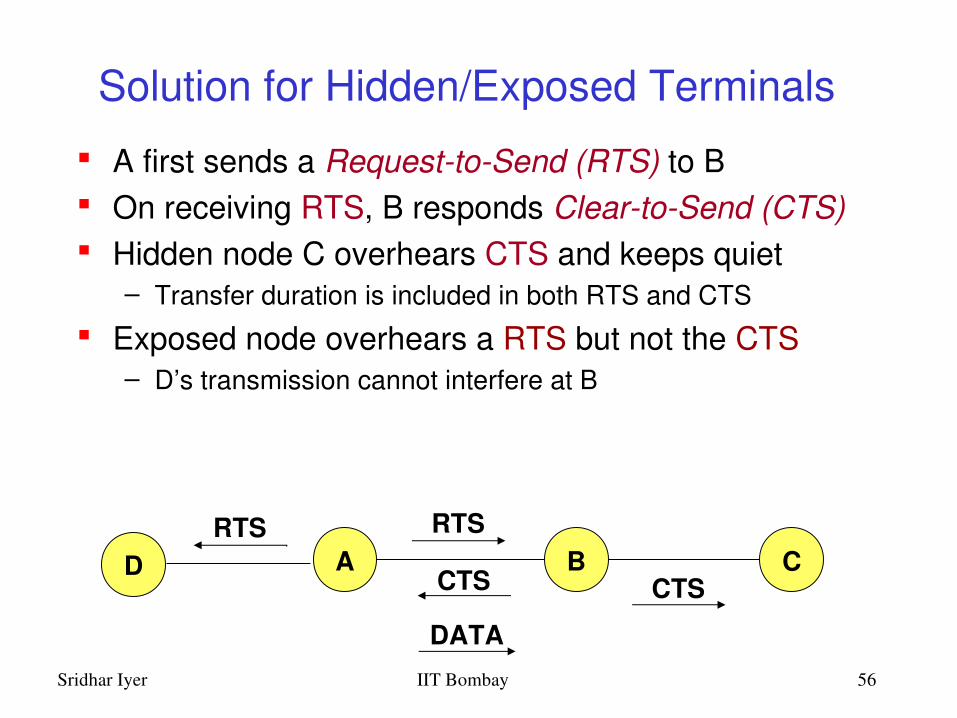
Solution for Hidden/Exposed Terminals
A first sends a RequesttoSend (RTS) to B On receiving RTS, B responds CleartoSend (CTS) Hidden node C overhears CTS and keeps quiet
– Transfer duration is included in both RTS and CTS
Exposed node overhears a RTS but not the CTS– D’s transmission cannot interfere at B
A B CRTS
CTS CTS
DATA
DRTS

Sridhar Iyer IIT Bombay 57
IEEE 802.11
Wireless LAN standard defined in the unlicensed spectrum (2.4 GHz and 5 GHz UNII bands)
Standards covers the MAC sublayer and PHY layers Three different physical layers in the 2.4 GHz band
– FHSS, DSSS and IR
OFDM based PHY layer in the 5 GHz band

Sridhar Iyer IIT Bombay 58
Components of IEEE 802.11 architecture
The basic service set (BSS) is the basic building block of an IEEE 802.11 LAN
The ovals can be thought of as the coverage area within which member stations can directly communicate
The Independent BSS (IBSS) is the simplest LAN. It may consist of as few as two stations
adhoc network BSS2BSS1

Sridhar Iyer IIT Bombay 59
802.11 adhoc network (DCF)
Direct communication within a limited range– Station (STA):
terminal with access mechanisms to the wireless medium
– Basic Service Set (BSS):group of stations using the same radio frequency
802.11 LAN
BSS2
802.11 LAN
BSS1
STA1
STA4
STA5
STA2
STA3
Source: Schiller

Sridhar Iyer IIT Bombay 60
Distribution System
Portal
802.x LAN
Access Point
802.11 LAN
BSS2
802.11 LAN
BSS1
Access Point
802.11 infrastructure network (PCF)Station (STA)
– terminal with access mechanisms to the wireless medium and radio contact to the access point
Basic Service Set (BSS)– group of stations using the same
radio frequencyAccess Point
– station integrated into the wireless LAN and the distribution system
Portal– bridge to other (wired) networks
Distribution System– interconnection network to form
one logical network (EES: Extended Service Set) based on several BSS
STA1
STA2 STA3
ESS
Source: Schiller
Sridhar Iyer IIT Bombay 61
Distribution System (DS) concepts
The Distribution system interconnects multiple BSSs 802.11 standard logically separates the wireless
medium from the distribution system – it does not preclude, nor demand, that the multiple media be same or different
An Access Point (AP) is a STA that provides access to the DS by providing DS services in addition to acting as a STA.
Data moves between BSS and the DS via an AP The DS and BSSs allow 802.11 to create a wireless
network of arbitrary size and complexity called the Extended Service Set network (ESS)

Sridhar Iyer IIT Bombay 62
802.11 in the TCP/IP stack
mobile terminal
access point
server
fixed terminal
application
TCP
802.11 PHY
802.11 MAC
IP
802.3 MAC
802.3 PHY
application
TCP
802.3 PHY
802.3 MAC
IP
802.11 MAC
802.11 PHY
LLC
infrastructure network
LLC LLC

Sridhar Iyer IIT Bombay 63
802.11 Layers and functions
PLCP Physical Layer Convergence Protocol
– clear channel assessment signal (carrier sense)
PMD Physical Medium Dependent
– modulation, coding PHY Management
– channel selection, MIB Station Management
– coordination of all management functions
PMD
PLCP
MAC
LLC
MAC Management
PHY Management
MAC– access mechanisms,
fragmentation, encryption MAC Management
– synchronization, roaming, MIB, power management
PH
YD
LC
Sta
tion
Man
agem
ent
7.8.1

Sridhar Iyer IIT Bombay 64
802.11 Physical layer
3 versions: 2 radio (typically 2.4 GHz), 1 IR– data rates 1, 2, or 11 Mbit/s
FHSS (Frequency Hopping Spread Spectrum)– spreading, despreading, signal strength, typically 1 Mbit/s– min. 2.5 frequency hops/s (USA), twolevel GFSK modulation
DSSS (Direct Sequence Spread Spectrum)– DBPSK modulation for 1 Mbit/s (Differential Binary Phase Shift Keying),
DQPSK for 2 Mbit/s (Differential Quadrature PSK)– preamble and header of a frame is always transmitted with 1 Mbit/s– chipping sequence: +1, 1, +1, +1, 1, +1, +1, +1, 1, 1, 1 (Barker code)– max. radiated power 1 W (USA), 100 mW (EU), min. 1mW
Infrared– 850950 nm, diffuse light, typ. 10 m range– carrier detection, energy detection, synchonization
Sridhar Iyer IIT Bombay 65
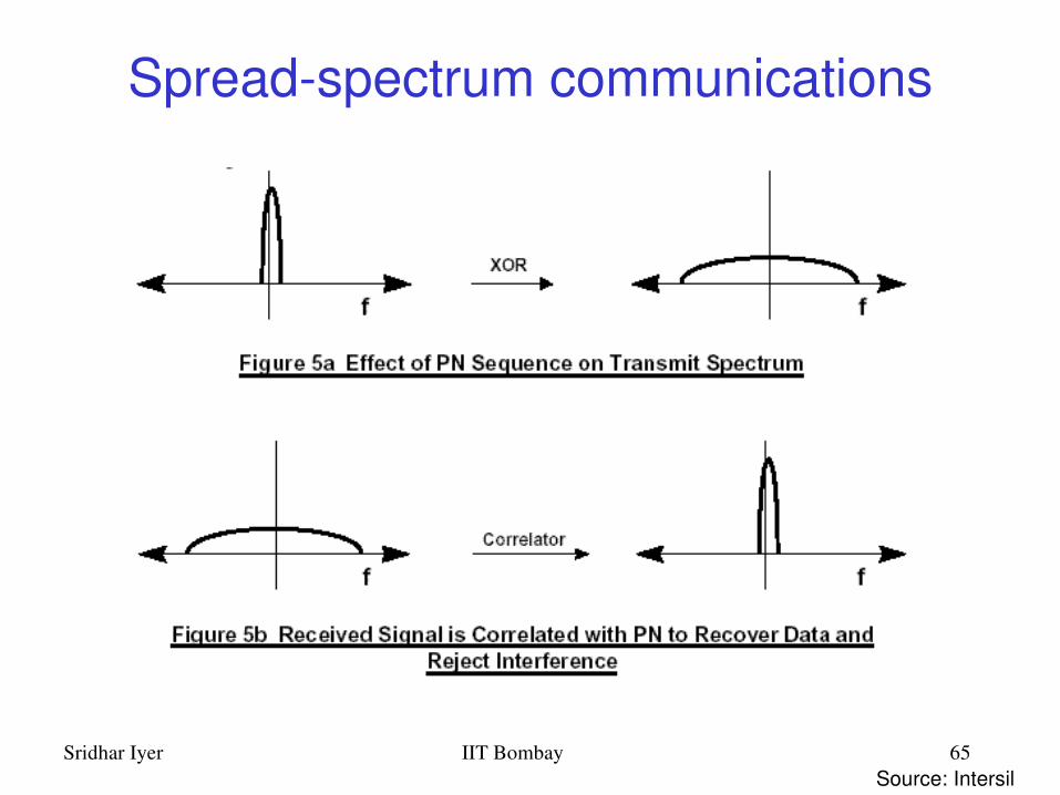
Spreadspectrum communications
Source: Intersil

Sridhar Iyer IIT Bombay 66
DSSS Barker Code modulation
Source: Intersil
Sridhar Iyer IIT Bombay 67
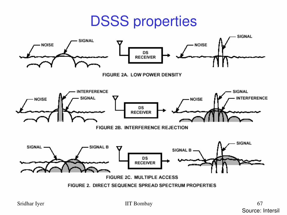
DSSS properties
Source: Intersil

Sridhar Iyer IIT Bombay 68
802.11 MAC layer
Traffic services– Asynchronous Data Service (mandatory) – DCF– TimeBounded Service (optional) PCF
Access methods– DCF CSMA/CA (mandatory)
• collision avoidance via randomized backoff mechanism• ACK packet for acknowledgements (not for broadcasts)
– DCF w/ RTS/CTS (optional)• avoids hidden terminal problem
– PCF (optional)• access point polls terminals according to a list

Sridhar Iyer IIT Bombay 69
802.11 Carrier Sensing
In IEEE 802.11, carrier sensing is performed – at the air interface (physical carrier sensing), and– at the MAC layer (virtual carrier sensing)
Physical carrier sensing – detects presence of other users by analyzing all detected
packets – Detects activity in the channel via relative signal strength
from other sources Virtual carrier sensing is done by sending MPDU duration
information in the header of RTS/CTS and data frames Channel is busy if either mechanisms indicate it to be
– Duration field indicates the amount of time (in microseconds) required to complete frame transmission
– Stations in the BSS use the information in the duration field to adjust their network allocation vector (NAV)
Sridhar Iyer IIT Bombay 70
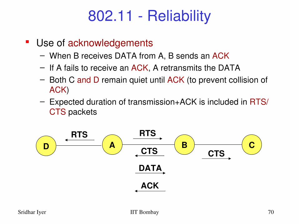
802.11 Reliability
Use of acknowledgements– When B receives DATA from A, B sends an ACK– If A fails to receive an ACK, A retransmits the DATA– Both C and D remain quiet until ACK (to prevent collision of
ACK)– Expected duration of transmission+ACK is included in RTS/
CTS packets
A B CRTS
CTS CTS
DATA
DRTS
ACK

Sridhar Iyer IIT Bombay 71
802.11 Priorities
defined through different inter frame spaces – mandatory idle time intervals between the transmission of frames
SIFS (Short Inter Frame Spacing)– highest priority, for ACK, CTS, polling response– SIFSTime and SlotTime are fixed per PHY layer – (10 µ s and 20 µ s respectively in DSSS)
PIFS (PCF IFS)– medium priority, for timebounded service using PCF– PIFSTime = SIFSTime + SlotTime
DIFS (DCF IFS)– lowest priority, for asynchronous data service– DCFIFS (DIFS): DIFSTime = SIFSTime + 2xSlotTime

Sridhar Iyer IIT Bombay 72
t
medium busy
DIFSDIFS
next frame
contention window(randomized backoffmechanism)
802.11 CSMA/CA
– station ready to send starts sensing the medium (Carrier Sense based on CCA, Clear Channel Assessment)
– if the medium is free for the duration of an InterFrame Space (IFS), the station can start sending (IFS depends on service type)
– if the medium is busy, the station has to wait for a free IFS, then the station must additionally wait a random backoff time (collision avoidance, multiple of slottime)
– if another station occupies the medium during the backoff time of the station, the backoff timer stops (fairness)
slot timedirect access if medium is free ≥ DIFS
Sridhar Iyer IIT Bombay 73
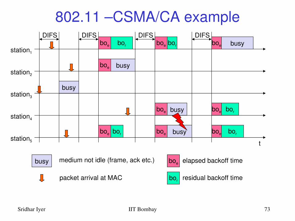
802.11 –CSMA/CA example
t
busy
boe
station1
station2
station3
station4
station5
packet arrival at MAC
DIFSboe
boe
boe
busy
elapsed backoff time
bor residual backoff time
busy medium not idle (frame, ack etc.)
bor
bor
DIFS
boe
boe
boe bor
DIFS
busy
busy
DIFSboe busy
boe
boe
bor
bor

Sridhar Iyer IIT Bombay 74
802.11 Collision Avoidance Collision avoidance: Once channel becomes idle, the
node waits for a randomly chosen duration before attempting to transmit
DCF – When transmitting a packet, choose a backoff interval in the
range [0,cw]; cw is contention window– Count down the backoff interval when medium is idle– Countdown is suspended if medium becomes busy– When backoff interval reaches 0, transmit RTS
Time spent counting down backoff intervals is part of MAC overhead

Sridhar Iyer IIT Bombay 75
DCF Example
data
waitB1 = 5
B2 = 15
B1 = 25
B2 = 20
data
wait
B1 and B2 are backoff intervalsat nodes 1 and 2cw = 31
B2 = 10

Sridhar Iyer IIT Bombay 76
802.11 Congestion Control
Contention window (cw) in DCF: Congestion control achieved by dynamically choosing cw
large cw leads to larger backoff intervals small cw leads to larger number of collisions
Binary Exponential Backoff in DCF:– When a node fails to receive CTS in response to
its RTS, it increases the contention window• cw is doubled (up to a bound CWmax)
– Upon successful completion data transfer, restore cw to CWmin

Sridhar Iyer IIT Bombay 77
802.11 CSMA/CA II
station has to wait for DIFS before sending data receivers acknowledge at once (after waiting for SIFS) if the
packet was received correctly (CRC) automatic retransmission of data packets in case of
transmission errors
t
SIFS
DIFS
data
ACK
waiting time
otherstations
receiver
senderdata
DIFS
contention

Sridhar Iyer IIT Bombay 78
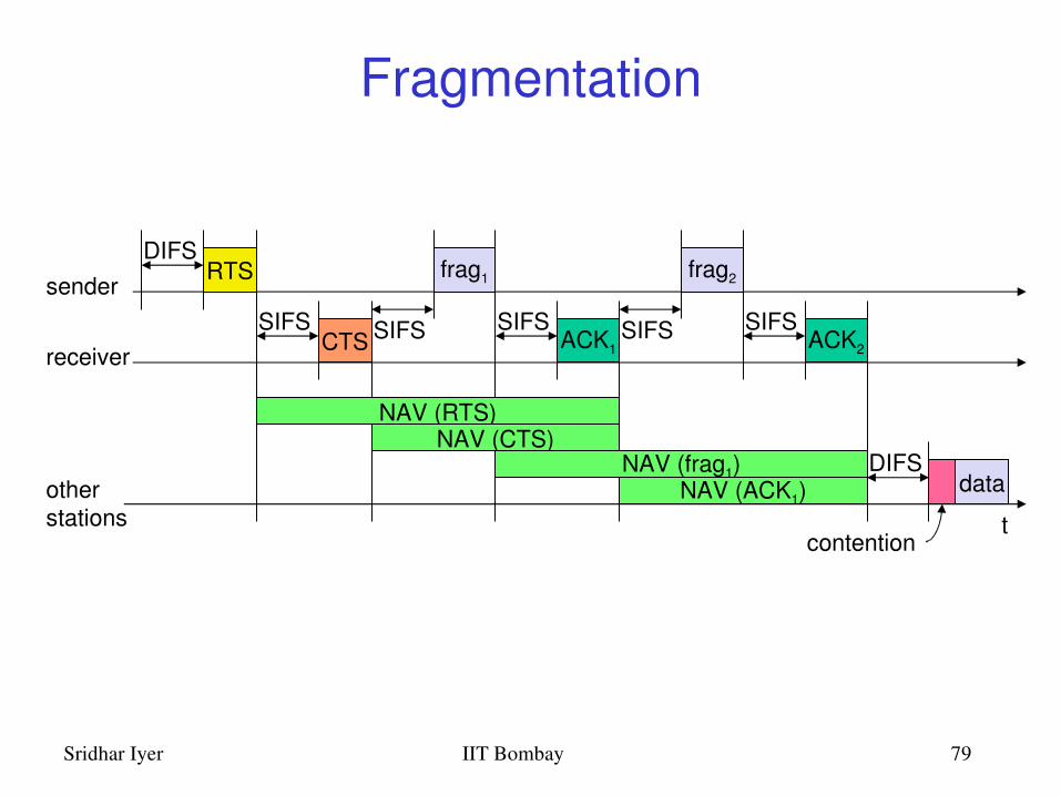
802.11 –RTS/CTS station can send RTS with reservation parameter after waiting for DIFS
(reservation determines amount of time the data packet needs the medium) acknowledgement via CTS after SIFS by receiver (if ready to receive) sender can now send data at once, acknowledgement via ACK other stations store medium reservations distributed via RTS and CTS
t
SIFS
DIFS
data
ACK
defer access
otherstations
receiver
senderdata
DIFS
contention
RTS
CTSSIFS SIFS
NAV (RTS)NAV (CTS)
Sridhar Iyer IIT Bombay 79
Fragmentation
t
SIFS
DIFS
data
ACK1
otherstations
receiver
senderfrag1
DIFS
contention
RTS
CTSSIFS SIFS
NAV (RTS)NAV (CTS)
NAV (frag1)NAV (ACK1)
SIFSACK2
frag2
SIFS

Sridhar Iyer IIT Bombay 80
802.11 Point Coordination Function

Sridhar Iyer IIT Bombay 81
802.11 PCF I
PIFS
stations‘NAV
wirelessstations
point coordinator
D1
U1
SIFS
NAV
SIFSD2
U2
SIFS
SIFS
SuperFramet0
medium busy
t1

Sridhar Iyer IIT Bombay 82
802.11 PCF II
tstations‘NAV
wirelessstations
point coordinator
D3
NAV
PIFSD4
U4
SIFS
SIFSCFend
contentionperiod
contention free period
t2 t3 t4

Sridhar Iyer IIT Bombay 83
CFP structure and Timing

Sridhar Iyer IIT Bombay 84
PCF Data transmission

Sridhar Iyer IIT Bombay 85
Polling Mechanisms
With DCF, there is no mechanism to guarantee minimum delay for timebound services
PCF wastes bandwidth (control overhead) when network load is light, but delays are bounded
With Round Robin (RR) polling, 11% of time was used for polling
This values drops to 4 % when optimized polling is used
Implicit signaling mechanism for STAs to indicate when they have data to send improves performance

Sridhar Iyer IIT Bombay 86
Coexistence of PCF and DCF
PC controls frame transfers during a Contention Free Period (CFP). – CFPoll control frame is used by the PC to invite a station to
send data– CFEnd is used to signal the end of the CFP
The CFP alternates with a CP, when DCF controls frame transfers– The CP must be large enough to send at least one
maximumsized MPDU including RTS/CTS/ACK
CFPs are generated at the CFP repetition rate and each CFP begins with a beacon frame

Sridhar Iyer IIT Bombay 87
802.11 Frame format Types
– control frames, management frames, data frames Sequence numbers
– important against duplicated frames due to lost ACKs Addresses
– receiver, transmitter (physical), BSS identifier, sender (logical) Miscellaneous
– sending time, checksum, frame control, data
FrameControl
DurationID
Address1
Address2
Address3
SequenceControl
Address4 Data CRC
2 2 6 6 6 62 402312bytes
version, type, fragmentation, security, ...

Sridhar Iyer IIT Bombay 88
Frame Control Field
Sridhar Iyer IIT Bombay 89
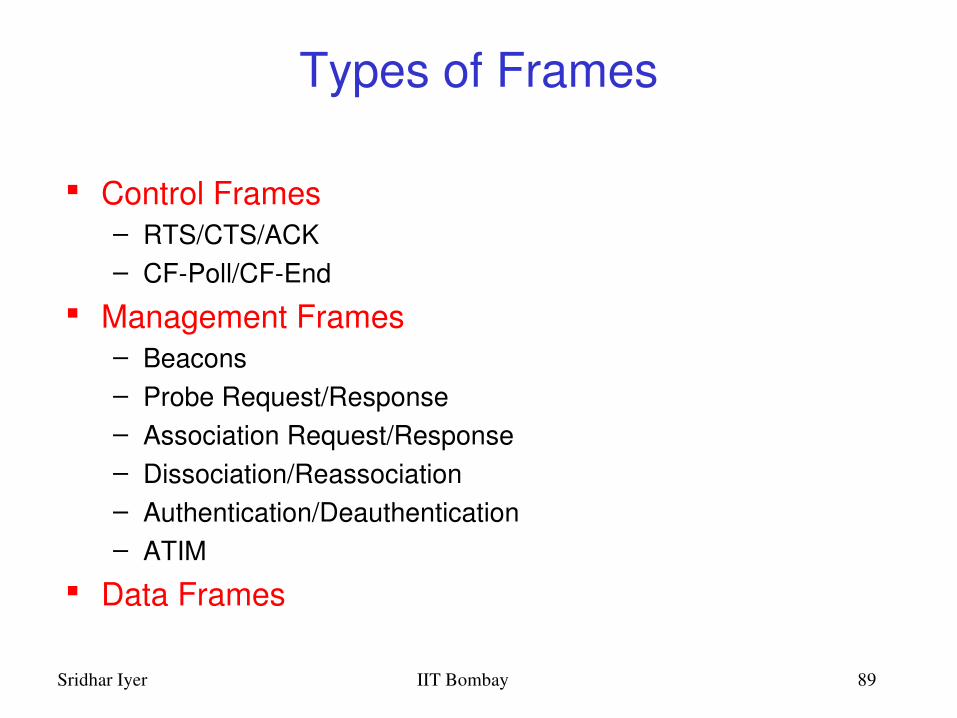
Types of Frames
Control Frames– RTS/CTS/ACK– CFPoll/CFEnd
Management Frames– Beacons– Probe Request/Response– Association Request/Response– Dissociation/Reassociation– Authentication/Deauthentication– ATIM
Data Frames

Sridhar Iyer IIT Bombay 90
MAC address formatscenario to DS from
DSaddress 1 address 2 address 3 address 4
adhoc network 0 0 DA SA BSSID infrastructurenetwork, from AP
0 1 DA BSSID SA
infrastructurenetwork, to AP
1 0 BSSID SA DA
infrastructurenetwork, within DS
1 1 RA TA DA SA
DS: Distribution SystemAP: Access PointDA: Destination AddressSA: Source AddressBSSID: Basic Service Set IdentifierRA: Receiver AddressTA: Transmitter Address

Sridhar Iyer IIT Bombay 91
802.11 MAC management
Synchronization– try to find a LAN, try to stay within a LAN– timer etc.
Power management– sleepmode without missing a message– periodic sleep, frame buffering, traffic measurements
Association/Reassociation– integration into a LAN– roaming, i.e. change networks by changing access points – scanning, i.e. active search for a network
MIB Management Information Base– managing, read, write

Sridhar Iyer IIT Bombay 92
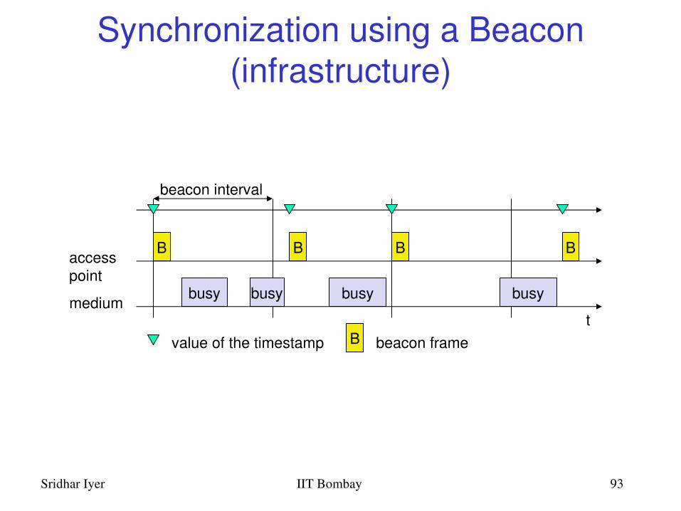
802.11 Synchronization
All STAs within a BSS are synchronized to a common clock – PCF mode: AP is the timing master
• periodically transmits Beacon frames containing Timing Synchronization function (TSF)
• Receiving stations accepts the timestamp value in TSF– DCF mode: TSF implements a distributed algorithm
• Each station adopts the timing received from any beacon that has TSF value later than its own TSF timer
This mechanism keeps the synchronization of the TSF timers in a BSS to within 4 µ s plus the maximum propagation delay of the PHY layer
Sridhar Iyer IIT Bombay 93
Synchronization using a Beacon (infrastructure)
beacon interval
tmedium
accesspoint
busy
B
busy busy busy
B B B
value of the timestamp B beacon frame

Sridhar Iyer IIT Bombay 94
Synchronization using a Beacon (adhoc)
tmedium
station1
busy
B1
beacon interval
busy busy busy
B1
value of the timestamp B beacon frame
station2
B2 B2
random delay

Sridhar Iyer IIT Bombay 95
802.11 Power management Idea: switch the transceiver off if not needed
– States of a station: sleep and awake Timing Synchronization Function (TSF)
– stations wake up at the same time Infrastructure
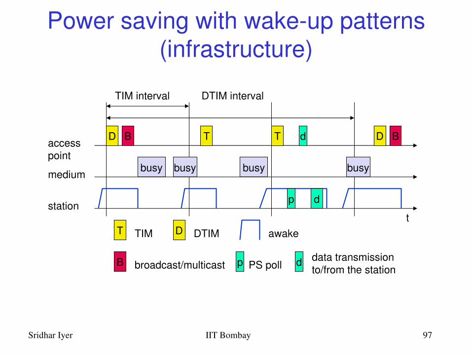
– Traffic Indication Map (TIM)• list of unicast receivers transmitted by AP
– Delivery Traffic Indication Map (DTIM)• list of broadcast/multicast receivers transmitted by AP
Adhoc– Adhoc Traffic Indication Map (ATIM)
• announcement of receivers by stations buffering frames• more complicated no central AP• collision of ATIMs possible (scalability?)

Sridhar Iyer IIT Bombay 96
802.11 Energy conservation
Power Saving in IEEE 802.11 (Infrastructure Mode)– An Access Point periodically transmits a beacon
indicating which nodes have packets waiting for them– Each power saving (PS) node wakes up periodically
to receive the beacon– If a node has a packet waiting, then it sends a PS
Poll• After waiting for a backoff interval in [0,CWmin]
– Access Point sends the data in response to PSpoll
Sridhar Iyer IIT Bombay 97
Power saving with wakeup patterns (infrastructure)
TIM interval
t
medium
accesspoint
busy
D
busy busy busy
T T D
T TIM D DTIM
DTIM interval
BB
B broadcast/multicast
station
awake
p PS poll
p
d
d
d data transmissionto/from the station

Sridhar Iyer IIT Bombay 98
Power saving with wakeup patterns (adhoc)
awake
A transmit ATIM D transmit datat
station1
B1 B1
B beacon frame
station2
B2 B2
random delay
A
a
D
d
ATIMwindow beacon interval
a acknowledge ATIM d acknowledge data

Sridhar Iyer IIT Bombay 99
802.11 Roaming No or bad connection in PCF mode? Then perform: Scanning
– scan the environment, i.e., listen into the medium for beacon signals or send probes into the medium and wait for an answer
Reassociation Request– station sends a request to one or several AP(s)
Reassociation Response– success: AP has answered, station can now participate– failure: continue scanning
AP accepts Reassociation Request– signal the new station to the distribution system– the distribution system updates its data base (i.e., location information)– typically, the distribution system now informs the old AP so it can release
resources

Sridhar Iyer IIT Bombay 100
Hardware
Original WaveLAN card (NCR)– 914 MHz Radio Frequency– Transmit power 281.8 mW– Transmission Range ~250 m (outdoors) at 2Mbps– SNRT 10 dB (capture)
WaveLAN II (Lucent)– 2.4 GHz radio frequency range– Transmit Power 30mW– Transmission range 376 m (outdoors) at 2 Mbps (60m
indoors)– Receive Threshold = –81dBm – Carrier Sense Threshold = 111dBm
Sridhar Iyer IIT Bombay 101
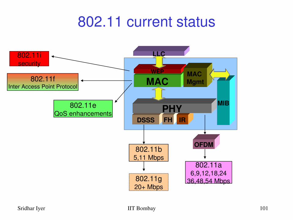
802.11 current status
MAC
MIB
DSSS FH IRPHY
WEP
LLC
MAC Mgmt
802.11b5,11 Mbps
802.11g20+ Mbps
802.11a6,9,12,18,24
36,48,54 Mbps
OFDM
802.11isecurity
802.11fInter Access Point Protocol
802.11eQoS enhancements

Sridhar Iyer IIT Bombay 102
IEEE 802.11 Summary
Infrastructure (PCF) and adhoc (DCF) modes
Signaling packets for collision avoidance– Medium is reserved for the duration of the transmission– Beacons in PCF– RTSCTS in DCF
Acknowledgements for reliability Binary exponential backoff for congestion control Power save mode for energy conservation

Sridhar Iyer IIT Bombay 103
Outline
Introduction and Overview Wireless LANs: IEEE 802.11 Mobile IP routing TCP over wireless GSM air interface GPRS network architecture Wireless application protocol Mobile agents Mobile ad hoc networks

Sridhar Iyer IIT Bombay 104
Traditional Routing
A routing protocol sets up a routing table in routers
Routing protocol is typically based on DistanceVector or LinkState algorithms
Sridhar Iyer IIT Bombay 105
Routing and Mobility
Finding a path from a source to a destination Issues
– Frequent route changes • amount of data transferred between route changes may
be much smaller than traditional networks– Route changes may be related to host movement– Low bandwidth links
Goal of routing protocols– decrease routingrelated overhead– find short routes– find “stable” routes (despite mobility)

Sridhar Iyer IIT Bombay 106
Mobile IP (RFC 3220): Motivation Traditional routing
– based on IP address; network prefix determines the subnet– change of physical subnet implies
• change of IP address (conform to new subnet), or• special routing table entries to forward packets to new subnet
Changing of IP address– DNS updates take to long time– TCP connections break– security problems
Changing entries in routing tables– does not scale with the number of mobile hosts and frequent
changes in the location– security problems
Solution requirements– retain same IP address, use same layer 2 protocols– authentication of registration messages, …

Sridhar Iyer IIT Bombay 107
Mobile IP: Basic Idea
Router1
Router3
Router2
S MN
Home agent

Sridhar Iyer IIT Bombay 108
Mobile IP: Basic Idea
Router1
Router3
Router2
S MN
Home agent
Foreign agent
move
Packets are tunneledusing IP in IP
Sridhar Iyer IIT Bombay 109
Mobile IP: Terminology Mobile Node (MN)
– node that moves across networks without changing its IP address Home Agent (HA)
– host in the home network of the MN, typically a router– registers the location of the MN, tunnels IP packets to the COA
Foreign Agent (FA)– host in the current foreign network of the MN, typically a router– forwards tunneled packets to the MN, typically the default router
for MN Careof Address (COA)
– address of the current tunnel endpoint for the MN (at FA or MN)– actual location of the MN from an IP point of view
Correspondent Node (CN)– host with which MN is “corresponding” (TCP connection)
Sridhar Iyer IIT Bombay 110
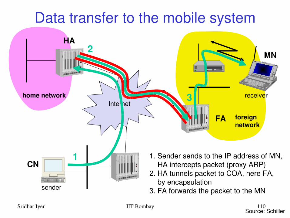
Data transfer to the mobile system
Internet
sender
FA
HA
MN
home network
foreignnetwork
receiver
1
2
3
1. Sender sends to the IP address of MN, HA intercepts packet (proxy ARP)2. HA tunnels packet to COA, here FA, by encapsulation3. FA forwards the packet to the MN
Source: Schiller
CN

Sridhar Iyer IIT Bombay 111
Data transfer from the mobile system
Internet
receiver
FA
HA
MN
home network
foreignnetwork
sender
1
1. Sender sends to the IP address of the receiver as usual, FA works as default router
Source: Schiller
CN

Sridhar Iyer IIT Bombay 112
Mobile IP: Basic Operation
Agent Advertisement– HA/FA periodically send advertisement messages into their
physical subnets– MN listens to these messages and detects, if it is in
home/foreign network– MN reads a COA from the FA advertisement messages
MN Registration – MN signals COA to the HA via the FA– HA acknowledges via FA to MN– limited lifetime, need to be secured by authentication
HA Proxy– HA advertises the IP address of the MN (as for fixed systems) – packets to the MN are sent to the HA – independent of changes in COA/FA
Packet Tunneling– HA to MN via FA

Sridhar Iyer IIT Bombay 113
Agent advertisement
preference level 1router address 1
#addressestype
addr. size lifetimechecksum
COA 1COA 2
type sequence numberlength
0 7 8 15 16 312423code
preference level 2router address 2
. . .
registration lifetime
. . .
R B H F M G V reserved

Sridhar Iyer IIT Bombay 114
Registration
t
MN HAregistrationrequest
registration
reply
t
MN FA HAregistrationrequestregistrationrequest
registration
reply
registration
reply

Sridhar Iyer IIT Bombay 115
Registration request
home agenthome address
type lifetime0 7 8 15 16 312423
rsv
identification
COA
extensions . . .
S B DMGV

Sridhar Iyer IIT Bombay 116
IPinIP encapsulation
IPinIPencapsulation (mandatory in RFC 2003)– tunnel between HA and COA
Careof address COAIP address of HA
TTLIP identification
IPinIP IP checksumflags fragment offset
lengthTOSver. IHL
IP address of MNIP address of CN
TTLIP identification
lay. 4 prot. IP checksumflags fragment offset
lengthTOSver. IHL
TCP/UDP/ ... payload

Sridhar Iyer IIT Bombay 117
Mobile IP: Other Issues
Reverse Tunneling– firewalls permit only “topological correct“ addresses– a packet from the MN encapsulated by the FA is now
topological correct
Optimizations– Triangular Routing
• HA informs sender the current location of MN
– Change of FA• new FA informs old FA to avoid packet loss, old FA now
forwards remaining packets to new FA

Sridhar Iyer IIT Bombay 118
Mobile IP Summary
Mobile node moves to new location Agent Advertisement by foreign agent Registration of mobile node with home agent Proxying by home agent for mobile node Encapsulation of packets Tunneling by home agent to mobile node via
foreign agent
Reverse tunneling Optimizations for triangular routing
Sridhar Iyer IIT Bombay 119
Outline
Introduction and Overview Wireless LANs: IEEE 802.11 Mobile IP routing TCP over wireless GSM air interface GPRS network architecture Wireless application protocol Mobile agents Mobile ad hoc networks
Sridhar Iyer IIT Bombay 120
Transmission Control Protocol (TCP)
Reliable ordered delivery – Acknowledgements and Retransmissions
Endtoend semantics– Acknowledgements sent to TCP sender confirm
delivery of data received by TCP receiver– Ack for data sent only after data has reached
receiver– Cumulative Ack
Implements congestion avoidance and control

Sridhar Iyer IIT Bombay 121
Window Based Flow Control
Sliding window protocol Window size minimum of
– receiver’s advertised window determined by available buffer space at the receiver
– congestion window determined by the sender, based on feedback from the network
2 3 4 5 6 7 8 9 10 11 131 12
Sender’s window
Acks received Not transmitted
Sridhar Iyer IIT Bombay 122
02468
101214
0 1 2 3 4 5 6 7 8
Time (round trips)
Cong
estio
n W
indo
w siz
e (se
gmen
ts)
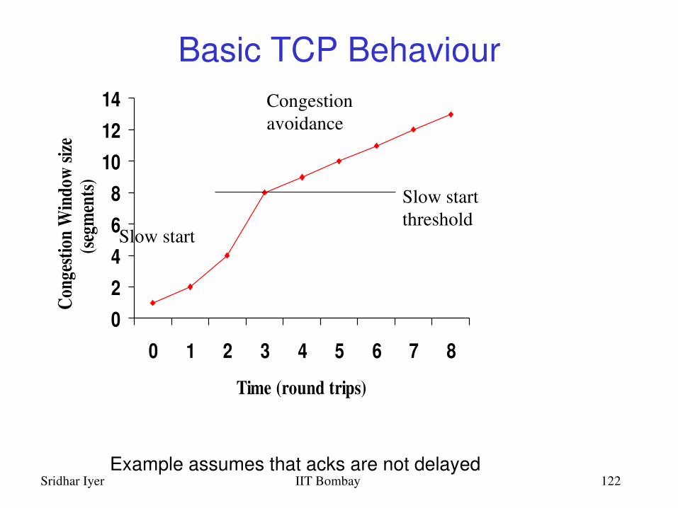
Slow start
Congestionavoidance
Slow start threshold
Example assumes that acks are not delayed
Basic TCP Behaviour

Sridhar Iyer IIT Bombay 123
TCP: Detecting Packet Loss
Retransmission timeout– Initiate Slow Start
Duplicate acknowledgements– Initiate Fast Retransmit
Assumes that ALL packet losses are due to congestion

Sridhar Iyer IIT Bombay 124
TCP after Timeout
0
5
10
15
20
25
0 3 6 9 12 15 20 22 25
Time (round trips)
Con
gest
ion
win
dow
(se
gmen
ts)
ssthresh = 8 ssthresh = 10
cwnd = 20
After timeout
Sridhar Iyer IIT Bombay 125
0
2
4
6
8
10
0 2 4 6 8 10 12 14
Time (round trips)
Wind
ow si
ze (s
egm
ents)
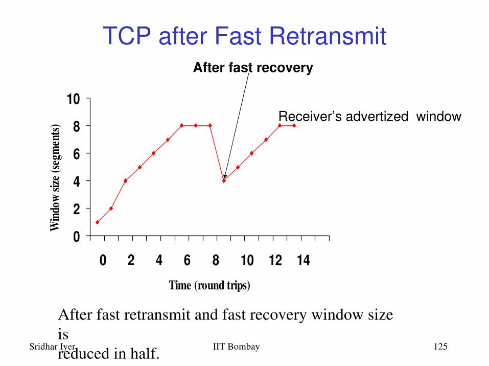
After fast retransmit and fast recovery window size isreduced in half.
Receiver’s advertized window
After fast recovery
TCP after Fast Retransmit

Sridhar Iyer IIT Bombay 126
Impact of Transmission Errors
Wireless channel may have bursty random errors
Burst errors may cause timeout Random errors may cause fast retransmit TCP cannot distinguish between packet losses
due to congestion and transmission errors
Unnecessarily reduces congestion window Throughput suffers

Sridhar Iyer IIT Bombay 127
Split Connection Approach
Endtoend TCP connection is broken into one connection on the wired part of route and one over wireless part of the route
Connection between wireless host MH and fixed host FH goes through base station BS
FHMH = FHBS + BSMH
FH MHBS
Base Station Mobile HostFixed Host

Sridhar Iyer IIT Bombay 128
ITCP: Split Connection Approach
wireless
physical
link
network
transport
application
physical
link
network
transport
application
physical
link
network
transport
application rxmt
PerTCP connection state
TCP connection TCP connection

Sridhar Iyer IIT Bombay 129
Snoop Protocol
Buffers data packets at the base station BS– to allow link layer retransmission
When dupacks received by BS from MH– retransmit on wireless link, if packet present in buffer– drop dupack
Prevents fast retransmit at TCP sender FH
FH MHBS

Sridhar Iyer IIT Bombay 130
Snoop Protocol
FH MHBSwireless
physical
link
network
transport
application
physical
link
network
transport
application
physical
link
network
transport
application
rxmt
Per TCPconnection state
TCP connection

Sridhar Iyer IIT Bombay 131
Impact of Handoffs
Split connection approach– hard state at base station must be moved to new base station
Snoop protocol– soft state need not be moved– while the new base station builds new state, packet losses may
not be recovered locally
Frequent handoffs a problem for schemes that rely on significant amount of hard/soft state at base stations– hard state should not be lost– soft state needs to be recreated to benefit performance
Sridhar Iyer IIT Bombay 132
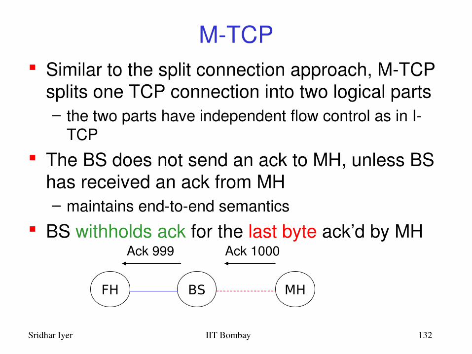
MTCP Similar to the split connection approach, MTCP
splits one TCP connection into two logical parts– the two parts have independent flow control as in I
TCP The BS does not send an ack to MH, unless BS
has received an ack from MH– maintains endtoend semantics
BS withholds ack for the last byte ack’d by MH
FH MHBS
Ack 1000Ack 999

Sridhar Iyer IIT Bombay 133
MTCP
When a new ack is received with receiver’s advertised window = 0, the sender enters persist mode
Sender does not send any data in persist mode– except when persist timer goes off
When a positive window advertisement is received, sender exits persist mode
On exiting persist mode, RTO and cwnd are same as before the persist mode

Sridhar Iyer IIT Bombay 134
FreezeTCP
MTCP needs help from base station– Base station withholds ack for one byte– The base station uses this ack to send a zero window
advertisement when a mobile host moves to another cell
FreezeTCP requires the receiver to send zero window advertisement (ZWA)
FH MHBS
MobileTCP receiver
Sridhar Iyer IIT Bombay 135
TCP over wireless summary
Assuming that packet loss implies congestion is invalid in wireless mobile environments
Invoking congestion control in response to packet loss is in appropriate
Several proposals to adapt TCP to wireless environments
Modifications at– Fixed Host– Base Station– Mobile Host

Sridhar Iyer IIT Bombay 136
Outline
Introduction and Overview Wireless LANs: IEEE 802.11 Mobile IP routing TCP over wireless GSM air interface GPRS network architecture Wireless application protocol Mobile agents Mobile ad hoc networks

Sridhar Iyer IIT Bombay 137
GSM: System Architecture

Sridhar Iyer IIT Bombay 138
Base Transceiver Station (BTS) One per cell Consists of high speed transmitter and receiver Function of BTS
– Provides two channelSignalling and Data ChannelMessage schedulingRandom access detection
– Performs error protection coding for the radio channel
• Rate adaptation
Identified by BTS Identity Code (BSIC)

Sridhar Iyer IIT Bombay 139
Base Station Controller (BSC) Controls multiple BTS Consists of essential control and protocol
intelligence entities Functions of BSC
– Performs radio resource management– Assigns and releases frequencies and time slots for all the
MSs in its area– Reallocation of frequencies among cells– Hand over protocol is executed here
– Time and frequency synchronization signals to BTSs– Time Delay Measurement and notification of an MS
to BTS– Power Management of BTS and MS

Sridhar Iyer IIT Bombay 140
Mobile Switching Center (MSC)
Switching node of a PLMN Allocation of radio resource (RR)
– Handover Mobility of subscribers
– Location registration of subscriber There can be several MSC in a PLMN

Sridhar Iyer IIT Bombay 141
Gateway MSC (GMSC)
Connects mobile network to a fixed network– Entry point to a PLMN
Usually one per PLMN Request routing information from the HLR and
routes the connection to the local MSC
Sridhar Iyer IIT Bombay 142
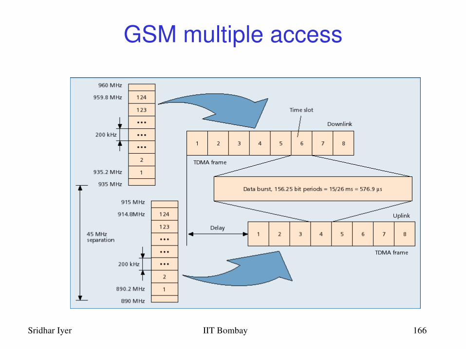
Air Interface: Physical Channel
Uplink/Downlink of 25MHz– 890 915 MHz for Up link– 935 960 MHz for Down link
Combination of frequency division and time division multiplexing
– FDMA– 124 channels of 200 kHz– 200 kHz guard band
– TDMA– Burst
Modulation used Gaussian Minimum Shift Keying (GMSK)

Sridhar Iyer IIT Bombay 143

Sridhar Iyer IIT Bombay 144
Bursts
Building unit of physical channel
Types of bursts– Normal– Synchronization– Frequency Correction– Dummy– Access

Sridhar Iyer IIT Bombay 145
Normal Burst
Normal Burst– 2*(3 head bit + 57 data bits + 1 signaling bit) + 26
training sequence bit + 8.25 guard bit
– Used for all except RACH, FSCH & SCH

Sridhar Iyer IIT Bombay 146
Air Interface: Logical Channel
Traffic Channel (TCH)
Signaling Channel– Broadcast Channel (BCH)– Common Control Channel (CCH)– Dedicated/Associated Control Channel
(DCCH/ACCH)

Sridhar Iyer IIT Bombay 147

Sridhar Iyer IIT Bombay 148
Traffic Channel
Transfer either encoded speech or user data Bidirectional
Full Rate TCH– Rate 22.4kbps– Bm interface
Half Rate TCH– Rate 11.2 kbps– Lm interface

Sridhar Iyer IIT Bombay 149
Full Rate Speech Coding Speech Coding for 20ms segments
– 260 bits at the output – Effective data rate 13kbps
Unequal error protection– 182 bits are protected
• 50 + 132 bits = 182 bits– 78 bits unprotected
Channel Encoding – Codes 260 bits into (8 x 57 bit blocks) 456 bits
Interleaving– 2 blocks of different set interleaved on a normal
burst (save damages by error bursts)

Sridhar Iyer IIT Bombay 150
3 4 87651 2
1 26 8.253 57
Speech 20 ms 20 ms
1 57 3
260 260
456 bit 456 bit
Speech Coder Speech Coder
Channel Encoding Channel Encoding
Interleaving
NORMAL BURST
Out of first 20 msOut of second 20ms

Sridhar Iyer IIT Bombay 151
T
Traffic Channel Structure for Full Rate Coding
23 4 18765432187651 2
1 2 3 4 5 6 7 8 9 10 11 12 13 14 15 16 17 26
T T T T T T T T TT T T S T T T T I
Slots
Bursts for Users allocated in Slot
T = TrafficS = Signal( contains information about the signal strength in neighboring cells)

Sridhar Iyer IIT Bombay 152
T
Traffic Channel Structure for Half Rate CodingT
23 4 18765432187651 2
1 2 3 4 5 6 7 8 9 10 11 12 13 14 15 16 17 26
T T T T T T S T T
Slots
Burst for one users
T =
1 2 3 4 5 6 7 8 9 10 11 12 13 14 15 16 17 26
T T T T T T T T S
Bursts for another users allocated in alternate Slots
Sridhar Iyer IIT Bombay 153
BCCH
Broadcast Control Channel (BCCH)↓– BTS to MS– Radio channel configuration
– Current cell + Neighbouring cells
– Synchronizing information– Frequencies + frame numbering
– Registration Identifiers – LA + Cell Identification (CI) + Base Station Identity Code
(BSIC)

Sridhar Iyer IIT Bombay 154
FCCH & SCH
Frequency Correction Channel – Repeated broadcast of FB
Synchronization Channel – Repeated broadcast of SB– Message format of SCH
PLMN color 3 bits
BS color 3 bits
T1 Superframeindex 11 bits
T2 multiframe index 11 bits
T3 block frameindex 3bits
BSIC 6 bits"FN 19bits

Sridhar Iyer IIT Bombay 155
RACH & SDCCH
Random Access Channel (RACH)– MS to BTS– Slotted Aloha– Request for dedicated SDCCH
Standalone Dedicated Control Channel (SDCCH)
– MS ↔ BTS– Standalone; Independent of TCH
Sridhar Iyer IIT Bombay 156
AGCH & PCH
Access Grant Channel (AGCH) – BTS to MS– Assign an SDCCH/TCH to MS
Paging Channel (PCH) – BTS to MS– Page MS

Sridhar Iyer IIT Bombay 157
SACCH & FACCH Slow Associated Control Channel (SACCH)
– MS ↔ BTS– Always associated with either TCH or SDCCH– Information
– Optimal radio operation; Commands for synchronization– Transmitter power control; Channel measurement
– Should always be active; as proof of existence of physical radio connection
Fast Associated Control Channel (FACCH) – MS ↔ BTS
– Handover– Preemptive multiplexing on a TCH, Stealing Flag (SF)

Sridhar Iyer IIT Bombay 158
Example: Incoming Call SetupMS ↓ BSS/MSC Paging request (PCH)MS ↑ BSS/MSC Channel request (RACH)MS ↓ BSS/MSC Immediate Assignment (AGCH)MS ↑ BSS/MSC Paging Response (SDCCH)MS ↓ BSS/MSC Authentication Request (SDCCH)MS ↑ BSS/MSC Authentication Response (SDCCH)MS ↓ BSS/MSC Cipher Mode Command (SDCCH)MS ↑ BSS/MSC Cipher Mode Compl. (SDCCH)MS ↓ BSS/MSC Setup (SDCCH)MS ↑ BSS/MSC Call Confirmation (SDCCH)MS ↓ BSS/MSC Assignment Command (SDCCH)MS ↑ BSS/MSC Assignment Compl. (FACCH)MS ↑ BSS/MSC Alert (FACCH)MS ↑ BSS/MSC Connect (FACCH)MS ↓ BSS/MSC Connect Acknowledge (FACCH)MS ↔BSS/MSC Data (TCH)

Sridhar Iyer IIT Bombay 159
YES
NO
NO
NO
YES
YES
Power On Scan Channels,monitor RF levels
Select the channel with highest RF level among the control channels
Scan the channel for theFCCH
IsFCCH detected?
Scan channel for SCH
IsSCH detected?
Read data from BCCHand determine is it BCCH?
Isthe current BCCHchannel included?
Camp on BCCH and start decoding
Select the channel withnext highest Rf level fromthe control list.
From the channel dataupdate the control channel list

Sridhar Iyer IIT Bombay 160
Adaptive Frame Synchronization
Timing Advance Advance in Tx time corresponding to
propagation delay
6 bit number used; hence 63 steps 63 bit period = 233 micro seconds (round trip
time)– 35 Kms

Sridhar Iyer IIT Bombay 161

Sridhar Iyer IIT Bombay 162
GSM: Channel Mapping Summary Logical channels
– Traffic Channels; Control Channels
Physical Channel– Time Slot Number; TDMA frame; RF Channel Sequence
Mapping in frequency– 124 channels, 200KHz spacing
Mapping in time– TDMA Frame, Multi Frame, Super Frame, Channel– Two kinds of multiframe:
– 26frame multiframe; usage Speech and Data– 51frame multiframe; usage Signalling
Sridhar Iyer IIT Bombay 163
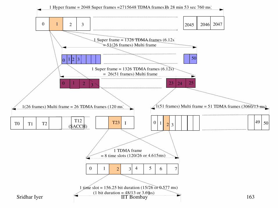
1 Hyper frame = 2048 Super frames =2715648 TDMA frames (3h 28 min 53 sec 760 ms)
1 Super frame = 1326 TDMA frames (6.12s) = 51(26 frames) Multi frame
1(26 frames) Multi frame = 26 TDMA frames (120 ms) 1(51 frames) Multi frame = 51 TDMA frames (3060/13 ms)
1 time slot = 156.25 bit duration (15/26 or 0.577 ms) (1 bit duration = 48/13 or 3.69s)
1 TDMA frame= 8 time slots (120/26 or 4.615ms)
0 1 2 3 2045 2046 2047
0 1 2 3 4 5 76
0 1 2
30 1 2
3 50
23 24 25
49 50T0 T1 I 1 2T2 3 T12(SACCH)
T23 0
1 Super frame = 1326 TDMA frames (6.12s) = 26(51 frames) Multi frame

Sridhar Iyer IIT Bombay 164
Outline
Introduction and Overview Wireless LANs: IEEE 802.11 Mobile IP routing TCP over wireless GSM air interface GPRS network architecture Wireless application protocol Mobile agents Mobile ad hoc networks

Sridhar Iyer IIT Bombay 165
GSM architecture
Source: Bettstetter et. al.
Sridhar Iyer IIT Bombay 166
GSM multiple access

Sridhar Iyer IIT Bombay 167
GSM call routing1. MSISDN
2. MSISDN
VLRHLR
AUCEIR
GMSC/IWF
MSC
BSC
BSC
BTS
BTS
BTS
ISDN
3. MSRN
4. MSRN
5. MSRN
6. TMSI
7. TMSI
7. TMSI
7. TMSI
8. TMSI
LA2
LA1
MS
MS
Sridhar Iyer IIT Bombay 168
Options for data transfer
Two enhancements to GSM for data– HSCSD High Speed Circuit Switched Data– GPRS General Packet Radio Service
Both have capacity to use new coding schemes and to make multislot allocation
GPRS, being a packet switched service, is known to be more efficient and flexible for data transfer purposes
It delivers circuit and packetswitched services in one mobile radio network
Sridhar Iyer IIT Bombay 169
GPRS features
Radio resources are allocated for only one or a few packets at a time, so GPRS enables– many users to share radio resources, and allow
efficient transport of packets– fast setup/access times– connectivity to external packet data n/w– volumebased charging
GPRS also carries SMS in data channels rather than signaling channels as in GSM

Sridhar Iyer IIT Bombay 170
GPRS Architecture

Sridhar Iyer IIT Bombay 171
GPRS Architecture
Requires addition of a new class of nodes called GSNs (GPRS Support Nodes)– SGSN: Serving GPRS Support Node,– GGSN: Gateway GPRS Support Node
BSC requires a PCU (Packet Control Unit) and various other elements of the GSM n/w require software upgrades
All GSNs are connected via an IPbased backbone. Protocol data units (PDUs) are encapsulated and tunneled between GSNs
Sridhar Iyer IIT Bombay 172
GGSN
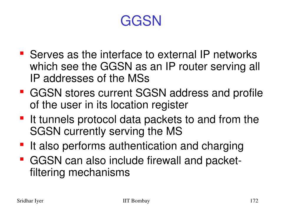
Serves as the interface to external IP networks which see the GGSN as an IP router serving all IP addresses of the MSs
GGSN stores current SGSN address and profile of the user in its location register
It tunnels protocol data packets to and from the SGSN currently serving the MS
It also performs authentication and charging GGSN can also include firewall and packet
filtering mechanisms
Sridhar Iyer IIT Bombay 173
SGSN
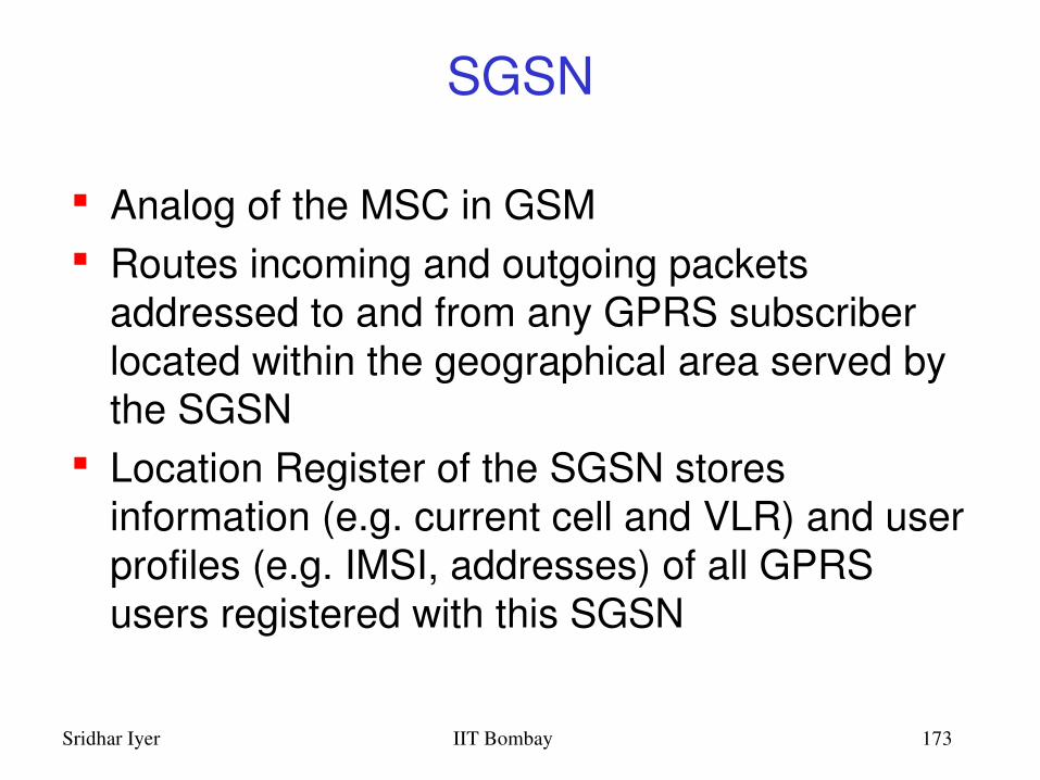
Analog of the MSC in GSM Routes incoming and outgoing packets
addressed to and from any GPRS subscriber located within the geographical area served by the SGSN
Location Register of the SGSN stores information (e.g. current cell and VLR) and user profiles (e.g. IMSI, addresses) of all GPRS users registered with this SGSN

Sridhar Iyer IIT Bombay 174
BSC and others
BSC must get a Packet Control Unit to– set up, supervise and disconnect packetswitched
calls– also support cell change, radio resource
configuration and channel assignment MSC/VLR, HLR and SMS Center must be
enhanced for interworking with GPRS MS must be equipped with the GPRS protocol
stack

Sridhar Iyer IIT Bombay 175
HLR Home Location Register
Shared database, with GSM Is enhanced with GPRS subscriber data and
routing information For all users registered with the network, HLR
keeps user profile, current SGSN and Packet Data Protocol (PDP) address(es) information
SGSN exchanges information with HLR e.g., informs HLR of the current location of the MS
When MS registers with a new SGSN, the HLR sends the user profile to the new SGSN
Sridhar Iyer IIT Bombay 176
MSC/VLRVisitor Location Register
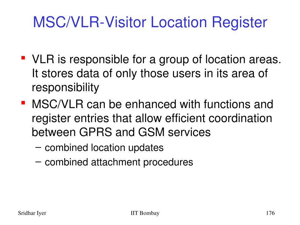
VLR is responsible for a group of location areas. It stores data of only those users in its area of responsibility
MSC/VLR can be enhanced with functions and register entries that allow efficient coordination between GPRS and GSM services– combined location updates– combined attachment procedures

Sridhar Iyer IIT Bombay 177
GPRS Transmission Plane

Sridhar Iyer IIT Bombay 178
Air Interface Um
Is one of the central aspects of GPRS– Concerned with communication between MS and
BSS at the physical, MAC and RLC layers– Physical channel dedicated to packet data traffic is
called a packet data channel (PDCH) Capacity on Demand:
– Allocation/Deallocation of PDCH to GPRS traffic is dynamic
– BSC controls resources in both directions– No conflicts on downlink– Conflicts in uplink are resolved using slotted ALOHA

Sridhar Iyer IIT Bombay 179
Data transfer between MS and SGSN
SNDCP transforms IP/X.25 packets into LLC frames, after optional header/data compression, segmentation and encryption
Maximum LLC frame size is 1600 bytes An LLC frame is segmented into RLC data blocks which
are coded into radio blocks Each radio block comprises four normal bursts (114 bits)
in consecutive TDMA frames RLC is responsible for transmission of data across air
interface, including error correction MAC layer performs medium allocation to requests,
including multislot allocation PHY layer is identical to GSM

Sridhar Iyer IIT Bombay 180
Data transfer between GSNs
Although the GPRS network consists of several different nodes, it represents only one IP hop
GTP enables tunneling of PDUs between GSNs, by adding routing information
Below GTP, TCP/IP and IP are used as the GPRS backbone protocols
Sridhar Iyer IIT Bombay 181
MS state model
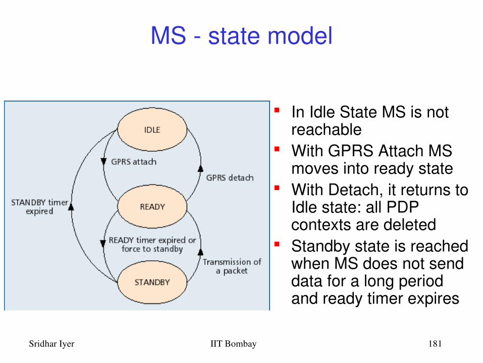
In Idle State MS is not reachable
With GPRS Attach MS moves into ready state
With Detach, it returns to Idle state: all PDP contexts are deleted
Standby state is reached when MS does not send data for a long period and ready timer expires

Sridhar Iyer IIT Bombay 182
GPRS – PDP context
MS gets a packet temporary mobile subscriber identity (pTMSI) during Attach
MS requests for one or more addresses used in the packet data network, e.g. IP address
GGSN creates a PDP context for each session– PDP type (IPV4), PDP address (IP) of MS, – requested quality of service (QoS) and address of GGSN
PDP context is stored in MS, SGSN and GGSN Mapping between the two addresses, enables GGSN to
transfer packets between MS and the PDN
Sridhar Iyer IIT Bombay 183
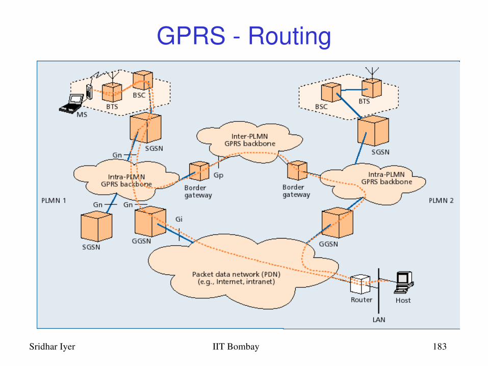
GPRS Routing

Sridhar Iyer IIT Bombay 184
GPRS Routing
MS from PLMN2 is visiting PLMN1. IP address prefix of MS is the same as GGSN2 Incoming packets to MS are routed to GGSN2 GGSN2 queries HLR and finds that MS is
currently in PLMN1 It encapsulates the IP packets and tunnels them
through the GPRS backbone to the appropriate SGSN of PLMN1
SGSN decapsulates and delivers to the MS

Sridhar Iyer IIT Bombay 185
GPRS Summary
Enables many users to share radio resources by dynamic, ondemand, multislot allocation
Provides connectivity to external packet data networks
Modification to the GSM airinterface Addition of new GPRS Support Nodes Assignment of PDP context to MS Enables volumebased charging as well as
duration based charging

Sridhar Iyer IIT Bombay 186
Outline
Introduction and Overview Wireless LANs: IEEE 802.11 Mobile IP routing TCP over wireless GSM air interface GPRS network architecture Wireless application protocol Mobile agents Mobile ad hoc networks
Sridhar Iyer IIT Bombay 187
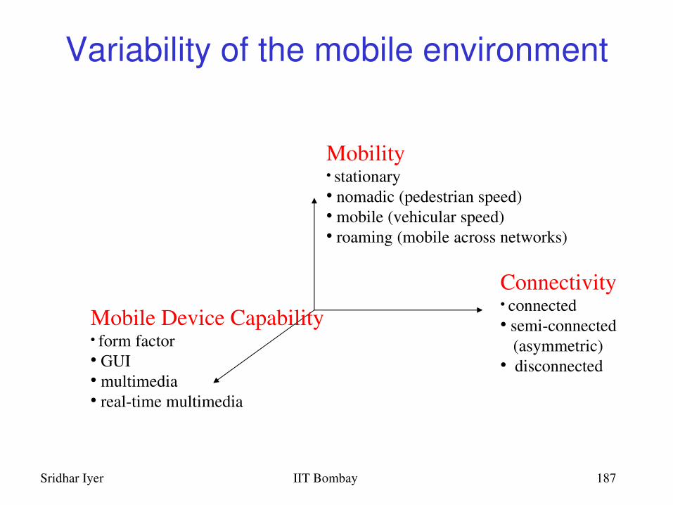
Variability of the mobile environment
Connectivity• connected• semiconnected (asymmetric)• disconnected
Mobile Device Capability• form factor• GUI• multimedia• realtime multimedia
Mobility• stationary• nomadic (pedestrian speed)• mobile (vehicular speed)• roaming (mobile across networks)
Sridhar Iyer IIT Bombay 188
Wireless Application Protocol (WAP)
HTTP/HTML have not been designed for mobile devices and applications
WAP empowers mobile users with wireless devices to easily access and interact with information and services.
A “standard” created by wireless and Internet companies to enable Internet access from a cellular phone
Sridhar Iyer IIT Bombay 189
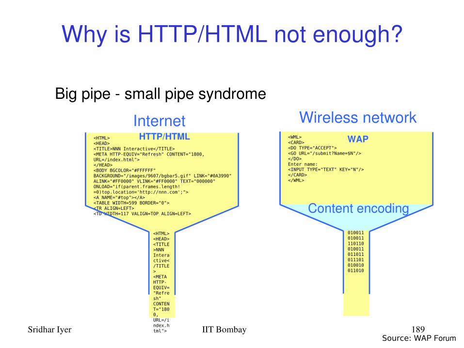
Why is HTTP/HTML not enough?
Big pipe small pipe syndromeWireless network
<HTML><HEAD><TITLE>NNN Interactive</TITLE><META HTTP-EQUIV="Refresh" CONTENT="1800, URL=/index.html"></HEAD><BODY BGCOLOR="#FFFFFF" BACKGROUND="/images/9607/bgbar5.gif" LINK="#0A3990" ALINK="#FF0000" VLINK="#FF0000" TEXT="000000" ONLOAD="if(parent.frames.length!=0)top.location='http://nnn.com';"> <A NAME="#top"></A><TABLE WIDTH=599 BORDER="0"><TR ALIGN=LEFT><TD WIDTH=117 VALIGN=TOP ALIGN=LEFT>
<HTML><HEAD><TITLE>NNN Interactive</TITLE><META HTTP-EQUIV="Refresh" CONTENT="1800, URL=/index.html">
Internet<WML><CARD><DO TYPE="ACCEPT"><GO URL="/submit?Name=$N"/></DO>Enter name:<INPUT TYPE="TEXT" KEY="N"/></CARD></WML>
010011010011110110010011011011011101010010011010
Content encoding
HTTP/HTML WAP
Source: WAP Forum

Sridhar Iyer IIT Bombay 190
WHY WAP?
Wireless networks and phones – have specific needs and requirements– not addressed by existing Internet technologies
WAP– Enables any data transport
• TCP/IP, UDP/IP, GUTS (IS135/6), SMS, or USSD.– Optimizes the content and airlink protocols– Utilizes plain Web HTTP 1.1 servers
• utilizes standard Internet markup language technology (XML) • all WML content is accessed via HTTP 1.1 requests
– WML UI components map well onto existing mobile phone UI• no reeducation of the endusers• leveraging market penetration of mobile devices

Sridhar Iyer IIT Bombay 191
WAP: main features Browser
– “Micro browser”, similar to existing web browsers Markup language
– Similar to HTML, adapted to mobile devices Script language
– Similar to Javascript, adapted to mobile devices Gateway
– Transition from wireless to wired world Server
– “Wap/Origin server”, similar to existing web servers Protocol layers
– Transport layer, security layer, session layer etc. Telephony application interface
– Access to telephony functions
Sridhar Iyer IIT Bombay 192
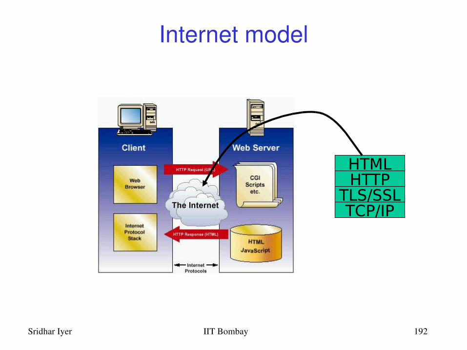
Internet model
HTMLHTTP
TLS/SSLTCP/IP

Sridhar Iyer IIT Bombay 193
Web Server
Content
CGIScripts
etc.
WM
L D
ecks
with
WM
LS
crip
t
WAP Gateway
WML Encoder
WMLScriptCompiler
Protocol Adapters
Client
WML
WMLScript
WTAI
Etc.
HTTPWSP/WTP
WAP architecture
Source: WAP Forum

Sridhar Iyer IIT Bombay 194
WAP Application Server
Content
ApplicationLogic
WM
L D
ecks
with
WM
LS
crip
t
WML Encoder
WMLScriptCompiler
Protocol Adapters
Client
WML
WMLScript
WTAI
Etc.
WSP/WTP
WAP application server
Source: WAP Forum
Sridhar Iyer IIT Bombay 195
WAP specifies
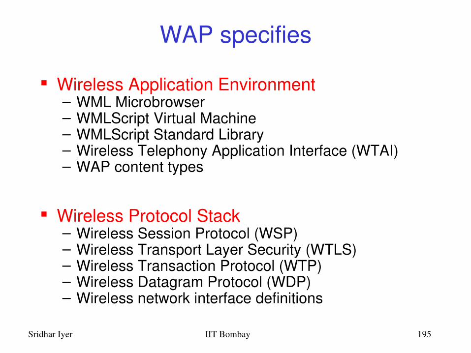
Wireless Application Environment– WML Microbrowser– WMLScript Virtual Machine– WMLScript Standard Library– Wireless Telephony Application Interface (WTAI)– WAP content types
Wireless Protocol Stack– Wireless Session Protocol (WSP)– Wireless Transport Layer Security (WTLS)– Wireless Transaction Protocol (WTP)– Wireless Datagram Protocol (WDP)– Wireless network interface definitions
Sridhar Iyer IIT Bombay 196
WAP stack
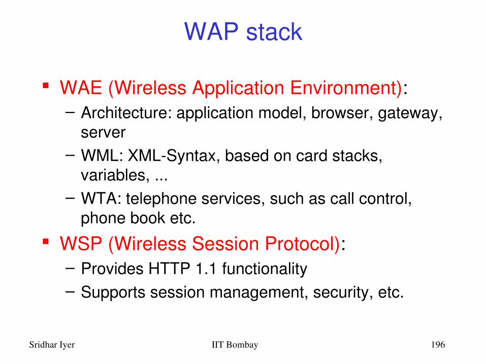
WAE (Wireless Application Environment):– Architecture: application model, browser, gateway,
server– WML: XMLSyntax, based on card stacks,
variables, ...– WTA: telephone services, such as call control,
phone book etc. WSP (Wireless Session Protocol):
– Provides HTTP 1.1 functionality – Supports session management, security, etc.

Sridhar Iyer IIT Bombay 197
WAP stack (contd.)
WTP (Wireless Transaction Protocol):– Provides reliable message transfer mechanisms– Based on ideas from TCP/RPC
WTLS (Wireless Transport Layer Security):– Provides data integrity, privacy, authentication functions– Based on ideas from TLS/SSL
WDP (Wireless Datagram Protocol):– Provides transport layer functions– Based on ideas from UDP
Content encoding, optimized for lowbandwidth channels, simple devices

Sridhar Iyer IIT Bombay 198
WDP: Wireless Datagram Protocol
Goals– create a worldwide interoperable transport system by
adapting WDP to the different underlying technologies– transmission services, such as SMS in GSM might change,
new services can replace the old ones WDP
– Transport layer protocol within the WAP architecture– uses the Service Primitive
• TUnitData.req .ind– uses transport mechanisms of different bearer technologies– offers a common interface for higher layer protocols– allows for transparent communication despite different
technologies– addressing uses port numbers– WDP over IP is UDP/IP

Sridhar Iyer IIT Bombay 199
WDP: service primitives
TSAP TSAPTDUnitdata.req(DA, DP, SA, SP, UD) TDUnitdata.ind
(SA, SP, UD) TDUnitdata.req(DA, DP, SA, SP, UD)
TDError.ind(EC) SAP: Service Access Point
DA: Destination Address
DP: Destination Port
SA: Source Address
SP: Source Port
UD: User Data
EC: Error Code
Source: Schiller

Sridhar Iyer IIT Bombay 200
WAP Over GSM CircuitSwitched
RAS Remote Access ServerIWF InterWorking Function
WSP
WAE
Subnetwork
IP
WSP
WAE Apps onOther Servers
WAP Proxy/Server
CSDRF
PPP
IP
Mobile
IWF
PSTNCircuit
CSDRF
ISP/RAS
SubnetworkPSTNCircuit
PPP
IP
WTP
UDP
WTP
UDP
Service, Protocol, Bearer: Example
Source: WAP Forum

Sridhar Iyer IIT Bombay 201
WAP Over GSM Short Message Service
SMS
WDP
WTP
WSP
WAE
SMS
Subnetwork
WDP
WDP Tunnel Protocol
Subnetwork
WDP TunnelProtocol
WTP
WSP
WAE Apps onother servers
SMSC
WAP Proxy/ServerMobile
Service, Protocol, Bearer: Example
Source: WAP Forum

Sridhar Iyer IIT Bombay 202
WTLS:Wireless Transport Layer Security Goals
– Provide mechanisms for secure transfer of content, for applications needing privacy, identification, message integrity and nonrepudiation
WTLS – is based on the TLS/SSL (Transport Layer Security) protocol– optimized for lowbandwidth communication channels– provides
• privacy (encryption)• data integrity (MACs)• authentication (publickey and symmetric)
– Employs special adapted mechanisms for wireless usage• Long lived secure sessions• Optimised handshake procedures• Provides simple data reliability for operation over datagram
bearers

Sridhar Iyer IIT Bombay 203
WTLS: secure session, full handshake
SECCreate.req(SA, SP, DA, DP, KES, CS, CM) SECCreate.ind
(SA, SP, DA, DP, KES, CS, CM)
originatorSECSAP
peerSECSAP
SECCreate.cnf(SNM, KR, SID, KES‘, CS‘, CM‘)
SECCreate.res(SNM, KR, SID, KES‘, CS‘, CM‘)
SECExchange.req
SECExchange.ind
SECExchange.res(CC)SECCommit.req SECExchange.cnf
(CC)SECCommit.ind
SECCommit.cnf
Source: Schiller
KES: Key Exchange Suite
CS: Cipher Suite
CM: Compression Mode
SNM: Sequence Number Mode
KR: Key Refresh Cycle
SID: Session Identifier
CC: Client Certificate

Sridhar Iyer IIT Bombay 204
WTP: Wireless Transaction Protocol Goals
– different transaction services that enable applications to select reliability, efficiency levels
– low memory requirements, suited to simple devices (< 10kbyte )
– efficiency for wireless transmission WTP
– supports peertopeer, client/server and multicast applications
– efficient for wireless transmission– support for different communication scenarios

Sridhar Iyer IIT Bombay 205
WTP transactions
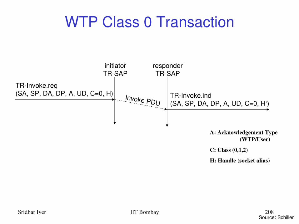
class 0: unreliable message transfer– unconfirmed Invoke message with no Result message– a datagram that can be sent within the context of an existing
Session class 1: reliable message transfer without result
message– confirmed Invoke message with no Result message– used for data push, where no response from the destination is
expected class 2: reliable message transfer with exactly one
reliable result message– confirmed Invoke message with one confirmed Result message– a single request produces a single reply

Sridhar Iyer IIT Bombay 206
WTP: services and protocols WTP (Transaction)
– provides reliable data transfer based on request/reply paradigm
• no explicit connection setup or tear down• optimized setup (data carried in first packet of protocol
exchange)• seeks to reduce 3way handshake on initial request
– supports• header compression• segmentation /reassembly• retransmission of lost packets• selectiveretransmission• port number addressing (UDP ports numbers)• flow control

Sridhar Iyer IIT Bombay 207
WTP services
message oriented (not stream) supports an Abort function for outstanding
requests supports concatenation of PDUs
supports two acknowledgement options– User acknowledgement – acks may be forced from the WTP user (upper layer)– Stack acknowledgement: default
Sridhar Iyer IIT Bombay 208
WTP Class 0 Transaction
TRInvoke.req(SA, SP, DA, DP, A, UD, C=0, H) Invoke PDU
TRInvoke.ind(SA, SP, DA, DP, A, UD, C=0, H‘)
initiatorTRSAP
responderTRSAP
Source: Schiller
A: Acknowledgement Type (WTP/User)
C: Class (0,1,2)
H: Handle (socket alias)

Sridhar Iyer IIT Bombay 209
WTP Class 1 Transaction, no user ack & user ack
TRInvoke.req(SA, SP, DA, DP, A, UD, C=1, H) Invoke PDU
TRInvoke.ind(SA, SP, DA, DP, A, UD, C=1, H‘)
initiatorTRSAP
responderTRSAP
Ack PDU
TRInvoke.res(H‘)
TRInvoke.cnf(H)
TRInvoke.req(SA, SP, DA, DP, A, UD, C=1, H) Invoke PDU
TRInvoke.ind(SA, SP, DA, DP, A, UD, C=1, H‘)
initiatorTRSAP
responderTRSAP
Ack PDUTRInvoke.cnf(H)
Source: Schiller

Sridhar Iyer IIT Bombay 210
WTP Class 2 Transaction,no user ack, no hold on
TRInvoke.req(SA, SP, DA, DP, A, UD, C=2, H) Invoke PDU
TRInvoke.ind(SA, SP, DA, DP, A, UD, C=2, H‘)
initiatorTRSAP
responderTRSAP
Result PDU
TRResult.req(UD*, H‘)
TRResult.ind(UD*, H)
Ack PDU
TRInvoke.cnf(H)
TRResult.res(H)
TRResult.cnf(H‘)
Source: Schiller

Sridhar Iyer IIT Bombay 211
WTP Class 2 Transaction, user ack
TRInvoke.req(SA, SP, DA, DP, A, UD, C=2, H) Invoke PDU
TRInvoke.ind(SA, SP, DA, DP, A, UD, C=2, H‘)
initiatorTRSAP
responderTRSAP
Result PDUTRResult.ind(UD*, H)
Ack PDU
TRInvoke.res(H‘)
TRInvoke.cnf(H) Ack PDU
TRResult.req(UD*, H‘)
TRResult.res(H)
TRResult.cnf(H‘)
Source: Schiller

Sridhar Iyer IIT Bombay 212
WSP Wireless Session Protocol
Goals– HTTP 1.1 functionality
• Request/reply, content type negotiation, ...– support of client/server transactions, push technology– key management, authentication, Internet security services
WSP Services– provides shared state between client and server, optimizes
content transfer– session management (establish, release, suspend, resume)– efficient capability negotiation– content encoding– Push
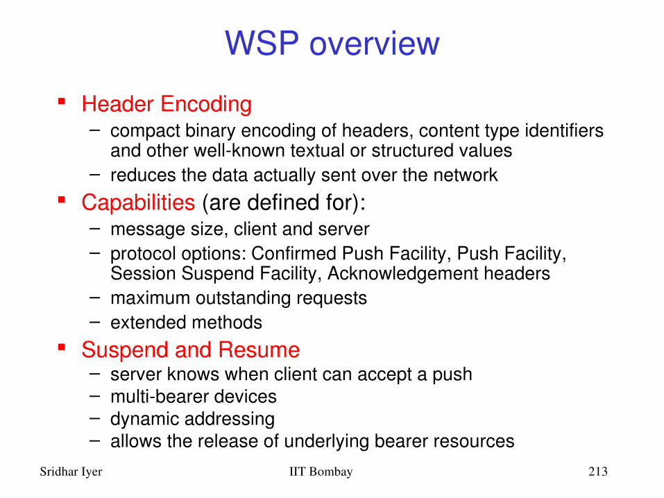
Sridhar Iyer IIT Bombay 213
WSP overview
Header Encoding– compact binary encoding of headers, content type identifiers
and other wellknown textual or structured values– reduces the data actually sent over the network
Capabilities (are defined for):– message size, client and server– protocol options: Confirmed Push Facility, Push Facility,
Session Suspend Facility, Acknowledgement headers– maximum outstanding requests– extended methods
Suspend and Resume– server knows when client can accept a push– multibearer devices– dynamic addressing– allows the release of underlying bearer resources
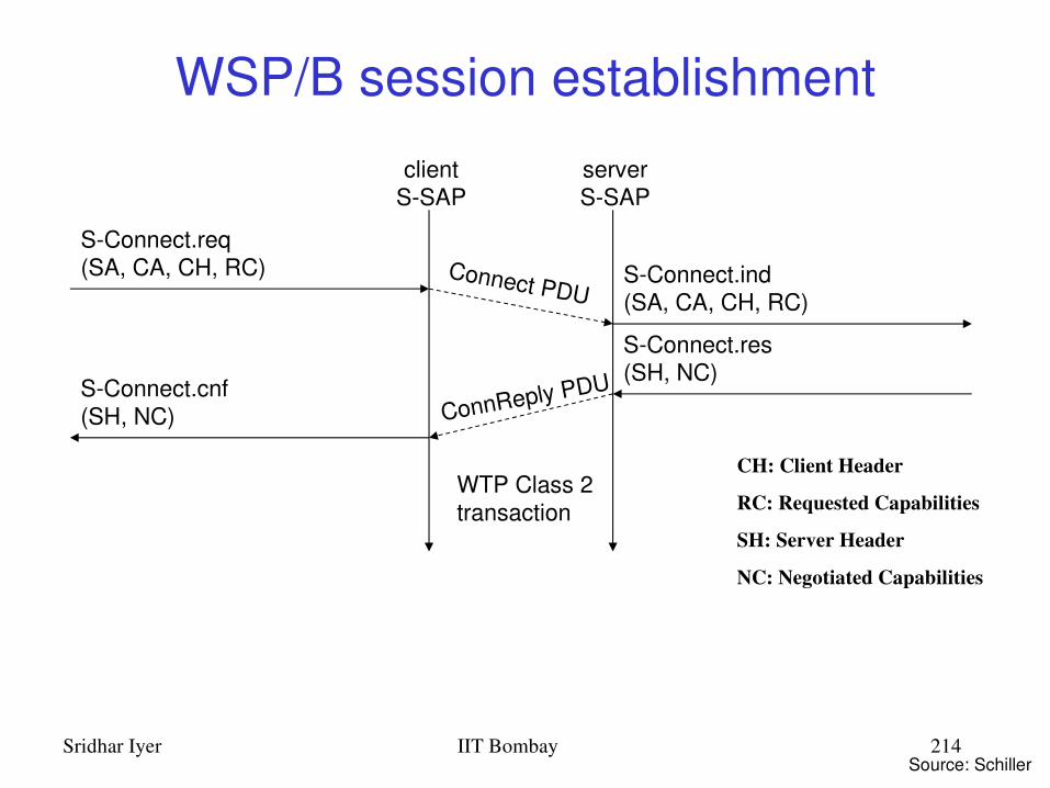
Sridhar Iyer IIT Bombay 214
WSP/B session establishment
SConnect.req(SA, CA, CH, RC) Connect PDU
SConnect.ind(SA, CA, CH, RC)
clientSSAP
serverSSAP
ConnReply PDU
SConnect.res(SH, NC)
SConnect.cnf(SH, NC)
WTP Class 2transaction
Source: Schiller
CH: Client Header
RC: Requested Capabilities
SH: Server Header
NC: Negotiated Capabilities

Sridhar Iyer IIT Bombay 215
WSP/B session suspend/resume
SSuspend.req Suspend PDUSSuspend.ind(R)
clientSSAP
serverSSAP
Reply PDUSResume.res
WTP Class 2transaction
SSuspend.ind(R)
~ ~SResume.req(SA, CA) SResume.ind
(SA, CA)Resume PDU
SResume.cnf
WTP Class 0transaction
Source: Schiller
R: Reason for disconnection

Sridhar Iyer IIT Bombay 216
WSP/B session termination
Disconnect PDUSDisconnect.ind(R)
clientSSAP
serverSSAP
SDisconnect.ind(R) WTP Class 0
transaction
SDisconnect.req(R)
Source: Schiller

Sridhar Iyer IIT Bombay 217
confirmed/nonconfirmed push
SPush.req(PH, PB)
clientSSAP
serverSSAP
ConfPush PDU
WTP Class 1transaction
SPush.ind(PH, PB)
SConfirmedPush.res(CPID)
SConfirmedPush.ind(CPID, PH, PB)
WTP Class 0transaction
Push PDU
SConfirmedPush.req(SPID, PH, PB)
clientSSAP
serverSSAP
SConfirmedPush.cnf(SPID)
Source: Schiller
PH: Push Header
PB: Push Body
SPID: Server Push ID
CPID: Client Push ID

Sridhar Iyer IIT Bombay 218
WAP Stack Summary WDP
– functionality similar to UDP in IP networks
WTLS– functionality similar to SSL/TLS (optimized for wireless)
WTP– Class 0: analogous to UDP– Class 1: analogous to TCP (without connection setup overheads)– Class 2: analogous to RPC (optimized for wireless)– features of “user acknowledgement”, “hold on”
WSP– WSP/B: analogous to http 1.1 (add features of suspend/resume)– method: analogous to RPC/RMI– features of asynchronous invocations, push (confirmed/unconfirmed)
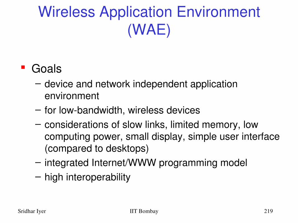
Sridhar Iyer IIT Bombay 219
Wireless Application Environment (WAE)
Goals– device and network independent application
environment– for lowbandwidth, wireless devices– considerations of slow links, limited memory, low
computing power, small display, simple user interface (compared to desktops)
– integrated Internet/WWW programming model – high interoperability

Sridhar Iyer IIT Bombay 220
WAE components
Architecture– Application model, Microbrowser, Gateway, Server
User Agents– WML/WTA/Others– content formats: vCard, vCalendar, Wireless Bitmap, WML..
WML– XMLSyntax, based on card stacks, variables, ...
WMLScript– procedural, loops, conditions, ... (similar to JavaScript)
WTA– telephone services, such as call control, text messages,
phone book, ... (accessible from WML/WMLScript)
Proxy (Method/Push)

Sridhar Iyer IIT Bombay 221
Origin Servers
WAE: logical model
webserver
other contentserver
Gateway Client
otherWAE
user agents
WMLuser agent
WTAuser agent
Push proxy
encodedrequest
request
encodedresponsewithcontent
responsewithcontent
pushcontent
encodedpushcontent
Method proxy
encoders&
decoders
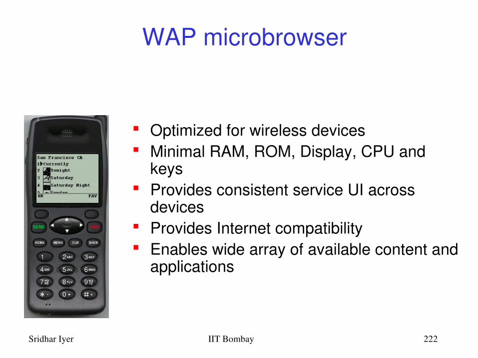
Sridhar Iyer IIT Bombay 222
WAP microbrowser
Optimized for wireless devices Minimal RAM, ROM, Display, CPU and
keys Provides consistent service UI across
devices Provides Internet compatibility Enables wide array of available content and
applications

Sridhar Iyer IIT Bombay 223
WML: Wireless Markup Language
Tagbased browsing language:– Screen management (text,
images)– Data input (text, selection
lists, etc.)– Hyperlinks & navigation
support
Takes into account limited display, navigation capabilities of devices
Content (XML)
XSL Processor
HTTP Browser
HTML StyleSheet
WML Browsers
WML Stylesheet

Sridhar Iyer IIT Bombay 224
WML
XMLbased language– describes only intent of interaction in an abstract
manner– presentation depends upon device capabilities
Cards and Decks– document consists of many cards– User interactions are split into cards– Explicit navigation between cards– cards are grouped to decks– deck is similar to HTML page, unit of content
transmission Events, variables and state mgmt

Sridhar Iyer IIT Bombay 225
WML The basic unit is a card. Cards are grouped together into Decks Document ~ Deck
(unit of transfer) All decks must contain
– Document prologue• XML & document type declaration
– <WML> element• Must contain one or more cards
<?xml version="1.0"?><!DOCTYPE WML PUBLIC "-//WAPFORUM//DTD WML 1.0//EN"
"http://www.wapforum.org/DTD/wml.xml">
<WML> ... </WML>
WML File Structure
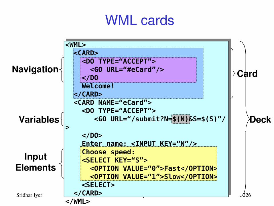
Sridhar Iyer IIT Bombay 226
WML cards
InputElements
Deck
CardNavigation
Variables
<WML> <CARD> <DO TYPE=“ACCEPT”> <GO URL=“#eCard”/> </DO Welcome! </CARD> <CARD NAME=“eCard”> <DO TYPE=“ACCEPT”> <GO URL=“/submit?N=$(N)&S=$(S)”/> </DO> Enter name: <INPUT KEY=“N”/> Choose speed: <SELECT KEY=“S”> <OPTION VALUE=“0”>Fast</OPTION> <OPTION VALUE=“1”>Slow</OPTION> <SELECT> </CARD></WML>
Sridhar Iyer IIT Bombay 227
Wireless Telephony Application (WTA)
Collection of telephony specific extensions– designed primarily for network operators
Example– calling a number (WML)wtai://wp/mc;07216086415
– calling a number (WMLScript)WTAPublic.makeCall("07216086415");
Implementation– Extension of basic WAE application model– Extensions added to standard WML/WMLScript browser– Exposes additional API (WTAI)
Sridhar Iyer IIT Bombay 228
WTA features
Extension of basic WAE application model– network model for interaction
• client requests to server• event signaling: server can push content to the client
– event handling• table indicating how to react on certain events from the
network• client may now be able to handle unknown events
– telephony functions• some application on the client may access telephony
functions
Sridhar Iyer IIT Bombay 229
WTA Interface
generic, highlevel interface to mobile’s telephony functions– setting up calls, reading and writing entries in
phonebook WTA API includes
– Call control– Network text messaging– Phone book interface– Event processing
Security model: segregation– Separate WTA browser– Separate WTA port

Sridhar Iyer IIT Bombay 230
Placing an outgoing call with WTAI:
Input Element
WTAI Call
<WML><CARD> <DO TYPE=“ACCEPT”> <GO URL=“wtai:cc/mc;$(N)”/> </DO> Enter phone number: <INPUT TYPE=“TEXT” KEY=“N”/></CARD></WML>
WTA Example (WML)
Source: WAP Forum

Sridhar Iyer IIT Bombay 231
WTA Logical Architecture
other WTAservers
Client
WAEservices
WTAuser agent
WAP Gateway
encoders&
decoders
other telephone networksWTA Origin Server
WTA & WMLserver
WMLScripts
WMLdecks
WTAservices
mobilenetwork
firewallthird partyorigin servers
network operatortrusted domain
Source: Schiller

Sridhar Iyer IIT Bombay 232
WTA Framework Components
Source: Heijden

Sridhar Iyer IIT Bombay 233
WTA User Agent
WTA User Agent– WML User agent with extended functionality– can access mobile device’s telephony functions
through WTAI– can store WTA service content persistently in a
repository– handles events originating in the mobile network

Sridhar Iyer IIT Bombay 234
WTA User Agent Context
Abstraction of execution space Holds current parameters, navigation history,
state of user agent Similar to activation record in a process
address space
Uses connectionmode and connectionless services offered by WSP
Specific, secure WDP ports on the WAP gateway

Sridhar Iyer IIT Bombay 235
WTA Events
Network notifies device of event (such as incoming call)
WTA events map to device’s native events WTA services are aware of and able to act on
these events
example: incoming call indication, call cleared, call connected
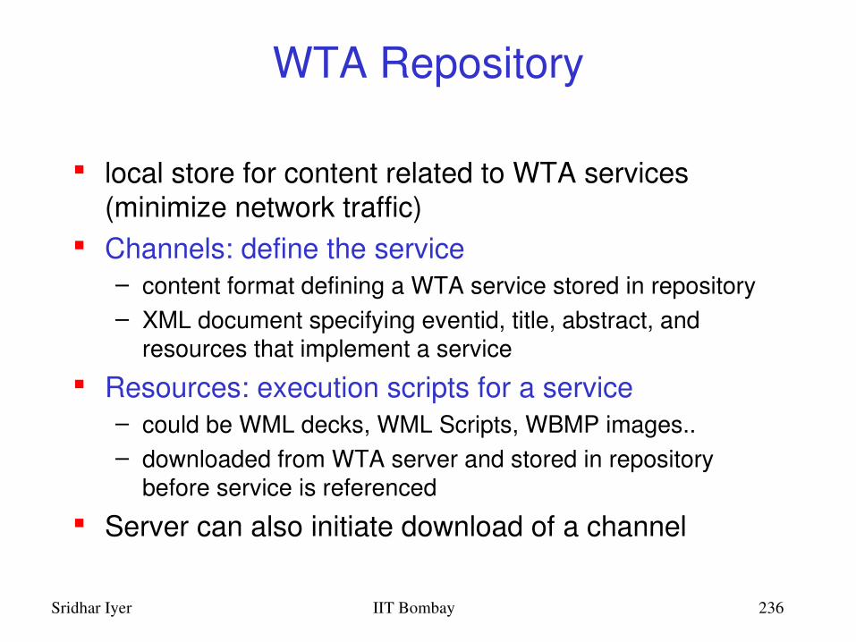
Sridhar Iyer IIT Bombay 236
WTA Repository
local store for content related to WTA services (minimize network traffic)
Channels: define the service– content format defining a WTA service stored in repository– XML document specifying eventid, title, abstract, and
resources that implement a service
Resources: execution scripts for a service– could be WML decks, WML Scripts, WBMP images..– downloaded from WTA server and stored in repository
before service is referenced
Server can also initiate download of a channel

Sridhar Iyer IIT Bombay 237
WTA Channels and Resources
Source: Heijden

Sridhar Iyer IIT Bombay 238
WTA Interface (public)
for third party WML content providers restricted set of telephony functions available to
any WAE User Agent– library functions
• make call: allows application to setup call to a valid tel number
• send DTMF tones: send DTMF tones through the setup call
user notified to grant permission for service execution– cannot be triggered by network events– example: Yellow pages service with “make call”
feature

Sridhar Iyer IIT Bombay 239
WTA Interface (network)
Network Common WTAI– WTA service provider is in operator’s domain– all WTAI features are accessible, including the
interface to WTA events– library functions
• Voicecall control: setup call, accept, release, send DTMF tones
• Network text: send text, read text, remove text (SMS)• Phonebook: write, read, remove phonebook entry• Call logs: last dialed numbers, missed calls, received calls• Miscellaneous: terminate WTA user agent, protect context
– user can give blanket permission to invoke a function– example: Voice mail service
Sridhar Iyer IIT Bombay 240
WTAI (network)
Network Specific WTAI– specific to type of bearer network
– example: GSM: call reject, call hold, call transfer, join multiparty, send USSD

Sridhar Iyer IIT Bombay 241
WTA: event handling
Event occurrence– WTA user agent could be executing and expecting
the event– WTA user agent could be executing and a
different event occurs– No service is executing
Event handling– channel for each event defines the content to be
processed upon reception of that event

Sridhar Iyer IIT Bombay 242
WTA: event binding
association of an event with the corresponding handler (channel)
Global binding: – channel corresponding to the event is stored in the repository– event causes execution of resources defined by the channel– example: voice mail service
Temporary binding:– resources to be executed are defined by the already executing
service– example: yellow pages lookup and call establishment
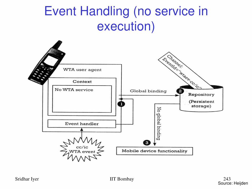
Sridhar Iyer IIT Bombay 243
Event Handling (no service in execution)
Source: Heijden
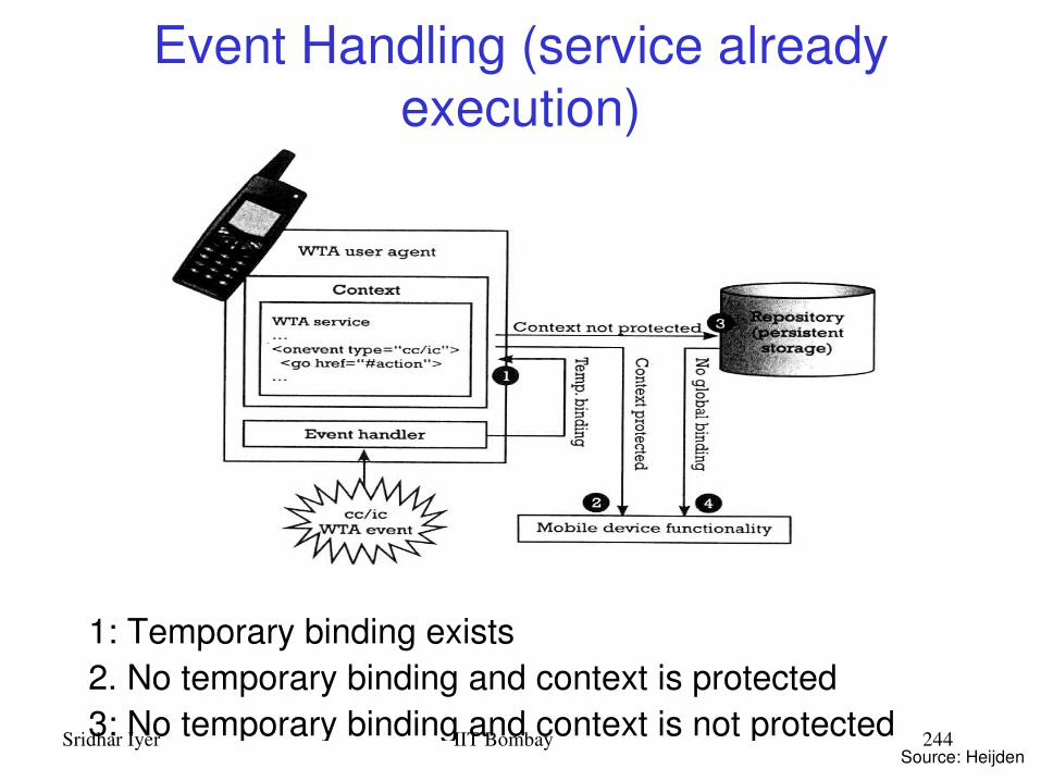
Sridhar Iyer IIT Bombay 244
Event Handling (service already execution)
1: Temporary binding exists2. No temporary binding and context is protected3: No temporary binding and context is not protected
Source: Heijden

Sridhar Iyer IIT Bombay 245
WAP Push Services Web push
– Scheduled pull by client (browser)• example: Active Channels
– no realtime alerting/response• example: stock quotes
Wireless push– accomplished by using the network itself
• example: SMS– limited to simple text, cannot be used as starting point for service
• example: if SMS contains news, user cannot request specific news item
WAP push– Network supported push of WML content
• example: Alerts or service indications– Precaching of data (channels/resources)

Sridhar Iyer IIT Bombay 246
WAP push framework
Source: Heijden

Sridhar Iyer IIT Bombay 247
Push Access Protocol
Based on request/response model Push initiator is the client Push proxy is the server Initiator uses HTTP POST to send push message to
proxy Initiator sends control information as an XML
document, and content for mobile (as WML) Proxy sends XML entity in response indicating
submission status Initiator can
– cancel previous push– query status of push– query status/capabilities of device

Sridhar Iyer IIT Bombay 248
Push Proxy Gateway
WAP stack (communication with mobile device) TCP/IP stack (communication with Internet push
initiator) Proxy layer does
– control information parsing– content transformation– session management– client capabilities– store and forward– prioritization– address resolution– management function
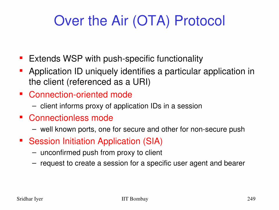
Sridhar Iyer IIT Bombay 249
Over the Air (OTA) Protocol
Extends WSP with pushspecific functionality Application ID uniquely identifies a particular application in
the client (referenced as a URI) Connectionoriented mode
– client informs proxy of application IDs in a session
Connectionless mode – well known ports, one for secure and other for nonsecure push
Session Initiation Application (SIA)– unconfirmed push from proxy to client– request to create a session for a specific user agent and bearer

Sridhar Iyer IIT Bombay 250
WAE Summary WML and WML Script
– analogous to HTML and JavaScript (optimized for wireless)– microbrowser user agent; compiler in the network
WTA– WTAI: different access rights for different applications/agents– WTA User Agent (analogy with operating systems)
• Context – Activation Record• Channel – Interrupt Handler• Resource – Shared routines invoked by interrupt handlers• Repository – Library of interrupt handlers
– feature of dynamically pushing the interrupt handler before the event
Push– no analogy in Internet

Sridhar Iyer IIT Bombay 251
Outline
Introduction and Overview Wireless LANs: IEEE 802.11 Mobile IP routing TCP over wireless GSM air interface GPRS network architecture Wireless application protocol Mobile agents Mobile ad hoc networks

Sridhar Iyer IIT Bombay 252
Call to server procedure
DataClient Serverresults
Procedure
DataClient ServerProcedure
Client Server
Code on Demand
DataClient Serverresults
Procedure
Remote Evaluation
Structuring Distributed Applications

Sridhar Iyer IIT Bombay 253
DataClient Server
DataServer
DataServer
Procedure+
State
DataServer
Procedure+
State
Procedure+
State
Procedure+
State
Mobile Agents
Procedure+
State

Sridhar Iyer IIT Bombay 254
Interaction Model
Client Server
Request
Response
Client/server communication
Client Server
Request
Response
Mobile agent communication
Mobile agent
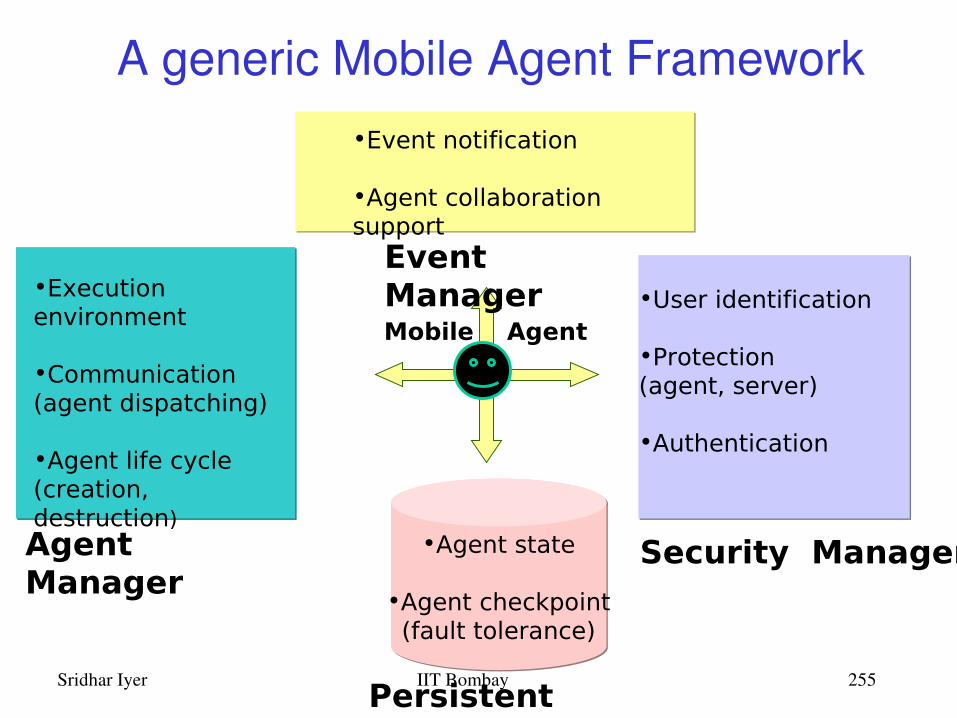
Sridhar Iyer IIT Bombay 255
A generic Mobile Agent Framework
•Agent state
•Agent checkpoint(fault tolerance)
•Execution environment
•Communication (agent dispatching)
•Agent life cycle (creation, destruction)
•Event notification
•Agent collaboration support
•User identification
•Protection (agent, server)
•Authentication
Persistent
Manager
Agent Manager
Event Manager
Security Manager
Mobile Agent

Sridhar Iyer IIT Bombay 256
Comprehensive Question Paper
Paper Assembler
To Distribution Center
Cloning
= Paper Setter Nodes = Install Agent= Fetch Agent
1
6
4
2
5
Partial Question Paper
3
Example: Student Examination Scenario

Sridhar Iyer IIT Bombay 257
Dynamic Upgrade

Sridhar Iyer IIT Bombay 258
DistributionServer
Exam Center Distribution
Server
Single copy of paper
c9611060
Separate Copy per user
List of Students enrolled……
Each Candidate get a Copy
1
4
3
2
Answered and Returned
5Each copy returned
Example: Distribution and Testing

Sridhar Iyer IIT Bombay 259
c9611060
Examiner B
Examiner A
Examiner D
Examiner C
Distributor
Results……
Agents collaborate to produce the final result
Objective Questions Evaluator
Distribution Server
Example: Evaluation and Results

Sridhar Iyer IIT Bombay 260
Mobile Agents Summary
Appears to be a useful mechanism for applications on mobile and wireless devices– Reduce the network load– Help in overcoming latency– Execute asynchronously and autonomously
Several issues yet to be addressed– Heavy frameworks– Interoperability– Security concerns

Sridhar Iyer IIT Bombay 261
Outline
Introduction and Overview Wireless LANs: IEEE 802.11 Mobile IP routing TCP over wireless GSM air interface GPRS network architecture Wireless application protocol Mobile agents Mobile ad hoc networks
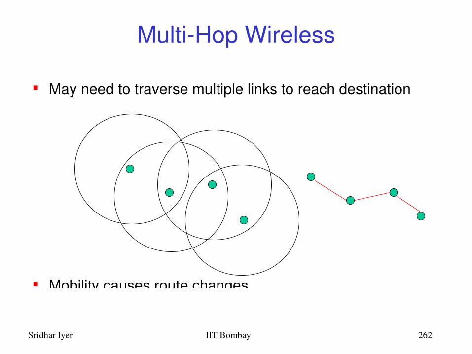
Sridhar Iyer IIT Bombay 262
MultiHop Wireless
May need to traverse multiple links to reach destination
Mobility causes route changes

Sridhar Iyer IIT Bombay 263
Mobile Ad Hoc Networks (MANET)
Host movement frequent Topology change frequent
No cellular infrastructure. Multihop wireless links. Data must be routed via intermediate nodes.
A B AB

Sridhar Iyer IIT Bombay 264
Many Applications
Ad hoc networks:– Do not need backbone infrastructure support– Are easy to deploy– Useful when infrastructure is absent, destroyed or impractical– Infrastructure may not be present in a disaster area or war zone
Applications:– Military environments– Emergency operations– Civilian environments
• taxi cab network• meeting rooms• sports stadiums
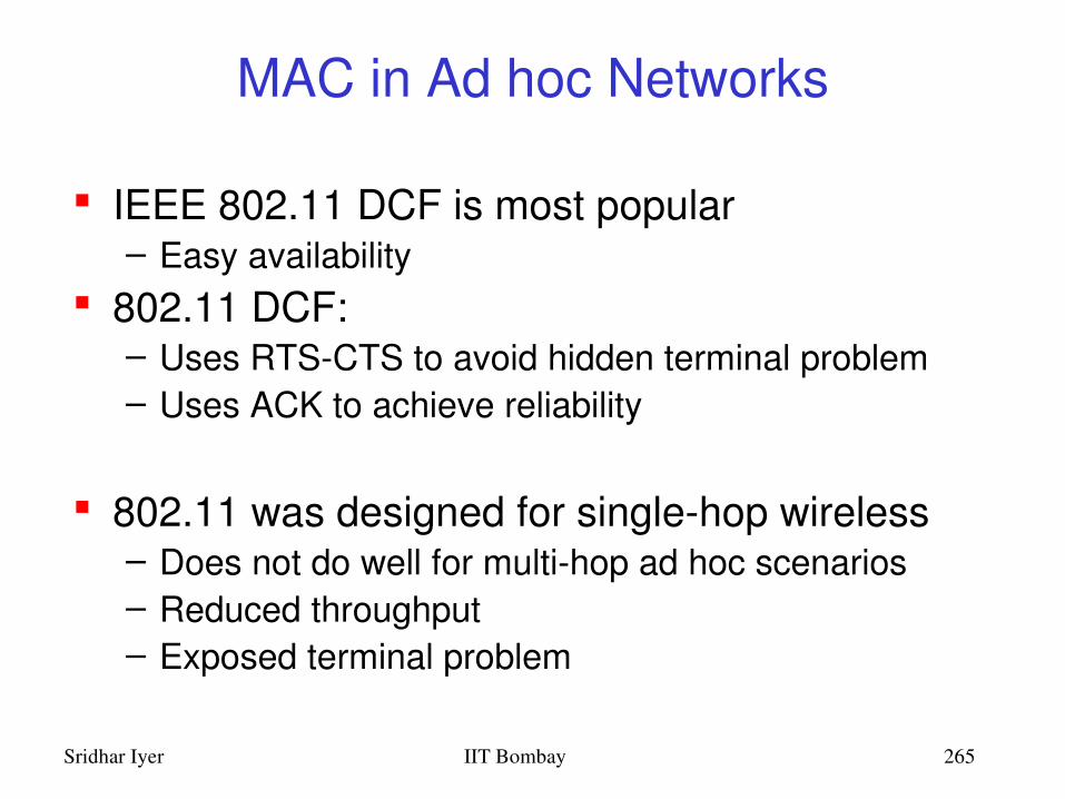
Sridhar Iyer IIT Bombay 265
MAC in Ad hoc Networks
IEEE 802.11 DCF is most popular– Easy availability
802.11 DCF:– Uses RTSCTS to avoid hidden terminal problem– Uses ACK to achieve reliability
802.11 was designed for singlehop wireless– Does not do well for multihop ad hoc scenarios– Reduced throughput– Exposed terminal problem

Sridhar Iyer IIT Bombay 266
Exposed Terminal Problem
– A starts sending to B.– C senses carrier, finds medium in use and has to
wait for A>B to end.– D is outside the range of A, therefore waiting is not
necessary.– A and C are “exposed” terminals
A BCD
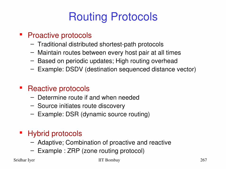
Sridhar Iyer IIT Bombay 267
Routing Protocols Proactive protocols
– Traditional distributed shortestpath protocols– Maintain routes between every host pair at all times– Based on periodic updates; High routing overhead– Example: DSDV (destination sequenced distance vector)
Reactive protocols– Determine route if and when needed– Source initiates route discovery– Example: DSR (dynamic source routing)
Hybrid protocols– Adaptive; Combination of proactive and reactive– Example : ZRP (zone routing protocol)

Sridhar Iyer IIT Bombay 268
Dynamic Source Routing (DSR)
Route Discovery Phase:– Initiated by source node S that wants to send packet to
destination node D– Route Request (RREQ) floods through the network– Each node appends own identifier when forwarding RREQ
Route Reply Phase:– D on receiving the first RREQ, sends a Route Reply (RREP)– RREP is sent on a route obtained by reversing the route
appended to received RREQ– RREP includes the route from S to D on which RREQ was
received by node D Data Forwarding Phase:
– S sends data to D by source routing through intermediate nodes
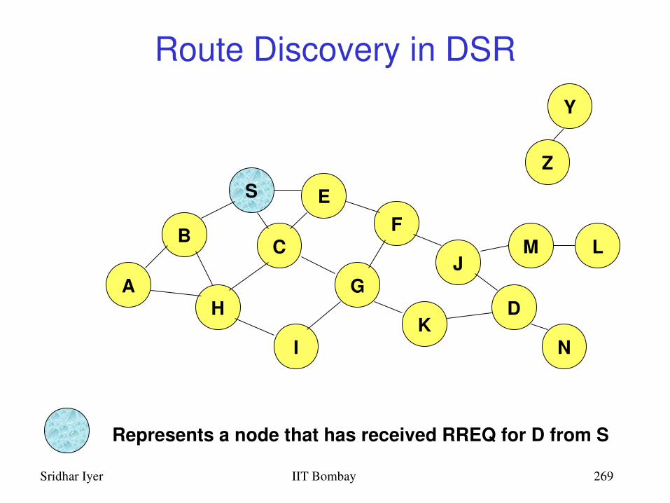
Sridhar Iyer IIT Bombay 269
Route Discovery in DSR
B
A
S EF
H
J
D
C
G
IK
Z
Y
Represents a node that has received RREQ for D from S
M
N
L
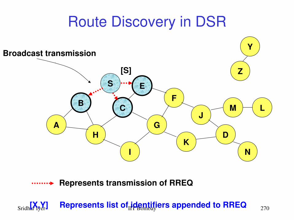
Sridhar Iyer IIT Bombay 270
Route Discovery in DSR
B
A
S EF
H
J
D
C
G
IK
Represents transmission of RREQ
Z
YBroadcast transmission
M
N
L
[S]
[X,Y] Represents list of identifiers appended to RREQ

Sridhar Iyer IIT Bombay 271
Route Discovery in DSR
B
A
S EF
H
J
D
C
G
IK
• Node H receives packet RREQ from two neighbors: potential for collision
Z
Y
M
N
L
[S,E]
[S,C]

Sridhar Iyer IIT Bombay 272
Route Discovery in DSR
B
A
S EF
H
J
D
C
G
IK
• Node C receives RREQ from G and H, but does not forward it again, because node C has already forwarded RREQ once
Z
Y
M
N
L
[S,C,G]
[S,E,F]

Sridhar Iyer IIT Bombay 273
Route Discovery in DSR
B
A
S EF
H
J
D
C
G
IK
Z
Y
M
• Nodes J and K both broadcast RREQ to node D• Since nodes J and K are hidden from each other, their transmissions may collide
N
L
[S,C,G,K]
[S,E,F,J]

Sridhar Iyer IIT Bombay 274
Route Discovery in DSR
B
A
S EF
H
J
D
C
G
IK
Z
Y
• Node D does not forward RREQ, because node D is the intended target of the route discovery
M
N
L
[S,E,F,J,M]

Sridhar Iyer IIT Bombay 275
Route Reply in DSR
B
A
S EF
H
J
D
C
G
IK
Z
Y
M
N
L
RREP [S,E,F,J,D]
Represents RREP control message

Sridhar Iyer IIT Bombay 276
Data Delivery in DSR
B
A
S EF
H
J
D
C
G
IK
Z
Y
M
N
L
DATA [S,E,F,J,D]
Packet header size grows with route length
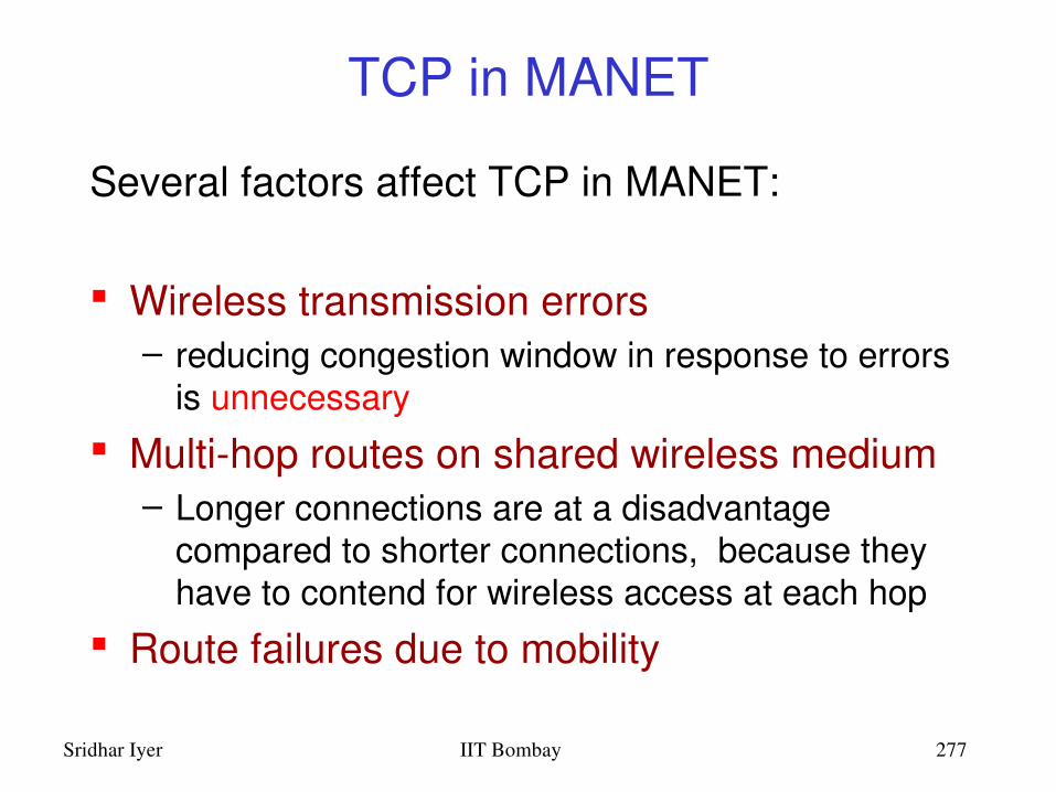
Sridhar Iyer IIT Bombay 277
TCP in MANET
Several factors affect TCP in MANET:
Wireless transmission errors– reducing congestion window in response to errors
is unnecessary Multihop routes on shared wireless medium
– Longer connections are at a disadvantage compared to shorter connections, because they have to contend for wireless access at each hop
Route failures due to mobility
Sridhar Iyer IIT Bombay 278
MANET Summary
Routing is the most studied problem Interplay of layers is being researched
Large number of simulation based expts Small number of field trials Very few reported deployments
Fertile area for imaginative applications– Standardizing protocols does not seem to be a
very good idea– Scope for proprietary solutions with limited interop

Sridhar Iyer IIT Bombay 279
References J. Schiller, “Mobile Communications”, Addison Wesley, 2000 802.11 Wireless LAN, IEEE standards, www.ieee.org Mobile IP, RFC 2002, RFC 334, www.ietf.org TCP over wireless, RFC 3150, RFC 3155, RFC 3449 A. Mehrotra, “GSM system engineering”, Artech House, 1997 Bettstetter, Vogel and Eberspacher, “GPRS: Architecture, Protocols
and Air Interface”, IEEE Communications Survey 1999, 3(3). M.v.d. Heijden, M. Taylor. “Understanding WAP”, Artech House, 2000 Mobile Ad hoc networks, RFC 2501
Others websites:– www.palowireless.com– www.gsmworld.com; www.wapforum.org– www.etsi.org; www.3gtoday.com

Sridhar Iyer IIT Bombay 280
Thank You
Other Tutorials at: www.it.iitb.ac.in/~sri
Contact Details:Sridhar IyerSchool of Information TechnologyIIT Bombay, Powai, Mumbai 400 076Phone: +912225767901Email: [email protected]