Embed Size (px)
Citation preview
Navid Nikaein
Mobile Communication Department
Mobile Advanced Networks
Position-based routing geometric, geographic, location-based
1 ©Navid Nikaein 2010

Reminder
In topology-based routing, each node has an ID/ADR
In contrast, in position-based routing, each node also obtains its own position Through direction and strength of the received signals Through GPS, Galileo
©Navid Nikaein 2
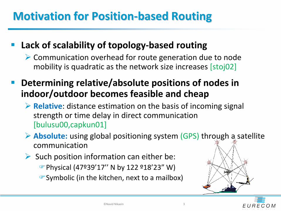
Motivation for Position-based Routing
Lack of scalability of topology-based routing Communication overhead for route generation due to node
mobility is quadratic as the network size increases [stoj02]
Determining relative/absolute positions of nodes in indoor/outdoor becomes feasible and cheap Relative: distance estimation on the basis of incoming signal
strength or time delay in direct communication [bulusu00,capkun01]
Absolute: using global positioning system (GPS) through a satellite communication
Such position information can either be: Physical (47º39’17’’ N by 122 º18’23” W) Symbolic (in the kitchen, next to a mailbox)
©Navid Nikaein 3

Motivation
Large network with high mobility and traffic load Localized algorithm (distributed in nature)
Local behavior achieves global objectives [stojm02] Think globally, act locally [streenstrup02]
Require accurate local location information Approximation of the position of destination The source S forwards a data packet to at least one neighbor
(A or M or both) closest to the destination D
©Navid Nikaein 5
D S M
M
A Render stateless routing: no routing table

Example
©Navid Nikaein 7
Carol
Bob
? Source: DCG ETH
Where is Carol?
Localized Algorithms ?
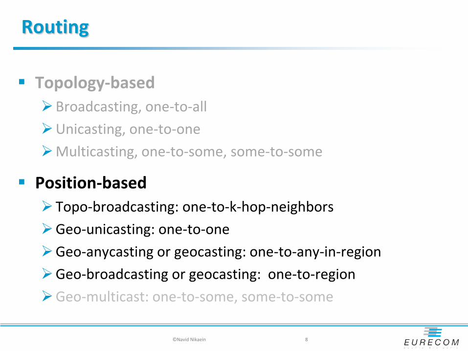
Routing
Topology-based Broadcasting, one-to-all Unicasting, one-to-one Multicasting, one-to-some, some-to-some
Position-based Topo-broadcasting: one-to-k-hop-neighbors Geo-unicasting: one-to-one Geo-anycasting or geocasting: one-to-any-in-region Geo-broadcasting or geocasting: one-to-region Geo-multicast: one-to-some, some-to-some
©Navid Nikaein 8

Position-Based Routing
©Navid Nikaein 9
S E
Topo-broadcast
Geo-unicast
Geo-unicast Geo-anycast D
Broadcast Range of E Destination
Geo-Area
Geo-broadcast
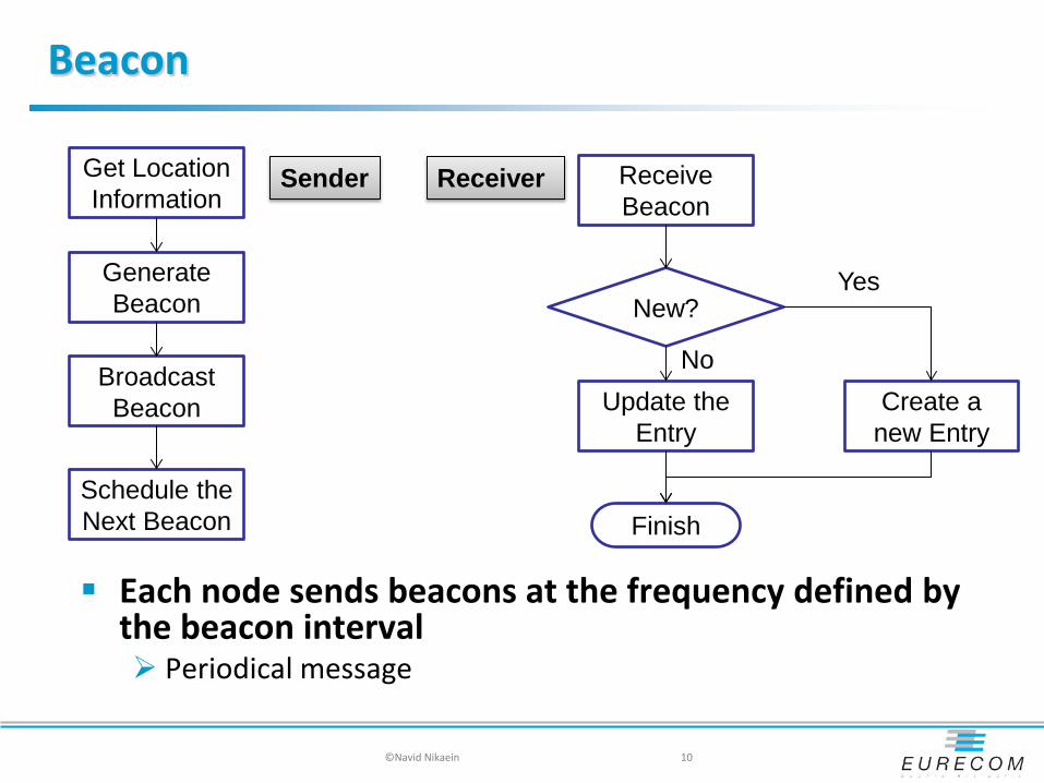
Beacon
Each node sends beacons at the frequency defined by the beacon interval Periodical message
©Navid Nikaein 10
Get Location Information
Generate Beacon
Broadcast Beacon
Schedule the Next Beacon
Receive Beacon
New?
Create a new Entry
Update the Entry
No
Yes
Finish
Sender Receiver
Building Blocks of Position-based Routing
Incorporates four fundamental building blocks: Beaconing : determine the position of the neighbors Location service: determines the position of destination Forwarding strategy: determines the next hop Recovery procedure: determine the next hop in case of
failure
©Navid Nikaein 14

Location Service
A process that enables the network to track and locate the current position of a node map node ID to node position
Operating on location server/directory/database Location service is a combination of: Location update
in charge of tracking occurs when a node changes location
Location search (location request/reply) in charge of locating occurs when a host wants to communicate with a mobile node whose
location is unknown to the requesting node
What are the different design choices of location service?
©Navid Nikaein 17

Location Service Design Choices
Do I keep track of positions to all destinations, or instead locating only those of immediate interests? For-no-one : no location update and full location search, LAR For-all: full location update and no location search, DREAM For-some: moderate location update and location search
How many nodes host the service? How many positions are maintained by the location server?
Trade-offs exist between the delay performance of location search and communication overhead of location update
©Navid Nikaein 18

LAR - Location-Aided Routing
Location information is used to limited the scope of flooding Node S knows that
Node D was at location L at time t0 Traveling with average speed v The current time is t1
Determine the expected zone Hold the current location of the destination By a circle centered at LD(t0) with radius v x (t1-t0) Refine the expected zone if some trajectory information is available (D is
traveling towards north)
Determine the request zone for route request Greater or equal than the expected zone Other regions around the expected zone Note: request zone affects the probability of successful route request
©Navid Nikaein 19

LAR - Location-Aided Routing
No guarantee that a path can be found consisting only of the hosts in a chosen request zone timeout expanded request zone
Two LAR schemes differ in determining the membership of request zone
©Navid Nikaein 20
LAR Scheme 1 LAR Scheme 2
LAR Scheme 1
The request zone is rectangular in shape Assume S knows that the node D was at location (Xd,Yd) at
time t0 Assume S knows the average speed v with which D can
move From above two, S defines the expected zone at time t1
with radius R = v(t1- t0) centered at location (Xd,Yd) The request zone is the smallest rectangle that includes
current location S and the expected zone such that the sides of the rectangle are parallel to the X and Y axes
Node D sends route reply message with its current location and time (may include average speed but simulation assumes all nodes knows each other’s average speed)
©Navid Nikaein 21
LAR Scheme 2
Node S includes two pieces of information with its route request Assume that S knows the location (Xd,Yd) of D at some time t0 which route
discovery is initiated by S at t1 where t1 ≥ to
S calculates its distance from location (Xd,Yd) denoted DISTs and included with the route request
The coordinate (Xd,Yd) are also included with the route request
When node I receives the route request from S, node I calculates its distance from (Xd,Yd) denoted DISTi and: For some parameter δ, if DISTs + δ ≥ DISTi, then I forwards request to its
neighbors – this request includes (Xd,Yd) and DISTi replacing original DISTs and (Xd,Yd) from S
Else DISTs + δ < DISTi, node I discards the route request
Each intermediate nodes repeat the process above
©Navid Nikaein 22
DREAM - A distance routing effect algorithm for
mobility
Proactively disseminate location information Each node maintains a location table of all nodes Flood if no entry for destination in table, otherwise Forward to all one-hop neighbors in the direction of the destination If no one-hop neighbor is found in the required direction, run the
recovery procedure (not specified in DREAM!)
Forwarding Direction is the line between S and D with the angle φ The angle φ is determined by an expected region Expected region centered at LD(t0) with radius r = vmax x (t1-t0)
©Navid Nikaein 23
DREAM
Distance Effect The farther away a nodes
gets, the slower it appears to move
Update more frequently the closed by nodes (packet age)
Mobility Effect The faster a node moves, the
higher is the update rate Adjust the frequency of
update as a function of mobility rate
No bandwidth wastage for no movement
©Navid Nikaein 24
This image cannot currently be displayed.
This image cannot currently be displayed.

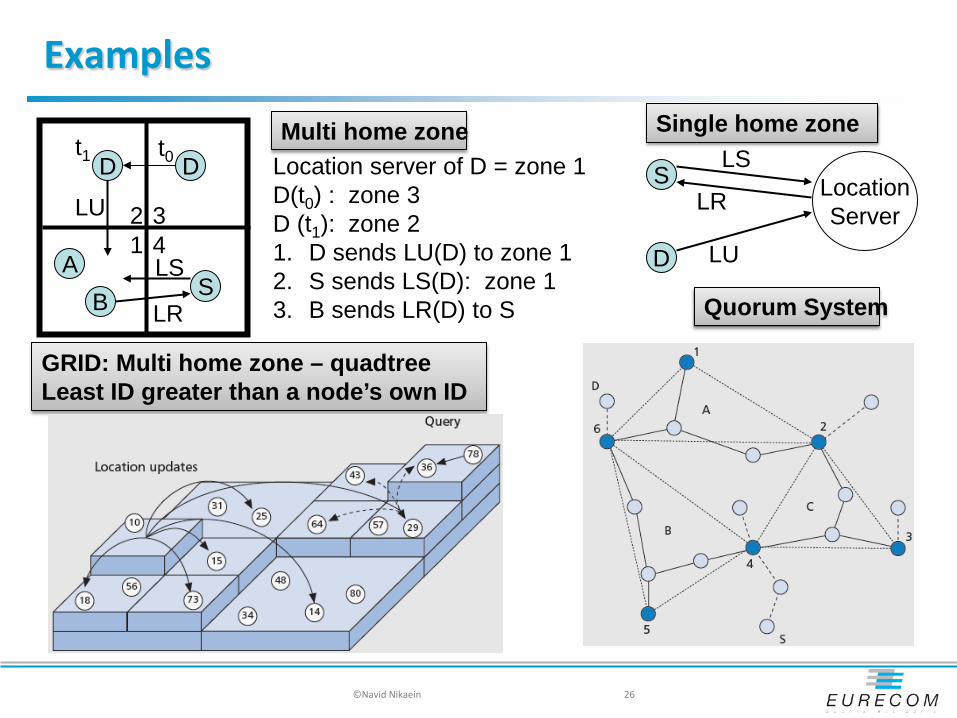
Location Service - Other variations
Single home zone: e.g. Mobile IP, virtual home region Define as a set of nodes, in a rectangular or a circle with radius R, close to a
known position This position is determined based on a well-known hash function All for some if home zones are uniformly distributed
Quorum system: e.g. uniform QS, double circle, Replicates location information at multiple nodes that are acting as location
servers Location updates (write operation) are sent to a subset of nodes (quorum) Location search (read operation) requests potentially a different subset Such subsets are designed such that their intersection is non-empty Can be configured to be all-for-all, all-for-some, or some-for-some
Multi home zone: e.g. grid based, graph-based Replicates location information at multiple positions in the area of ad hoc
networks
©Navid Nikaein 25
Examples
©Navid Nikaein 26
Quorum System
S Location Server
D LU
LS
LR Location server of D = zone 1 D(t0) : zone 3 D (t1): zone 2 1. D sends LU(D) to zone 1 2. S sends LS(D): zone 1 3. B sends LR(D) to S
D D
A B S
1 2 3
4
t0 t1
LU
LS
LR
GRID: Multi home zone – quadtree Least ID greater than a node’s own ID
Single home zone Multi home zone
Discussion
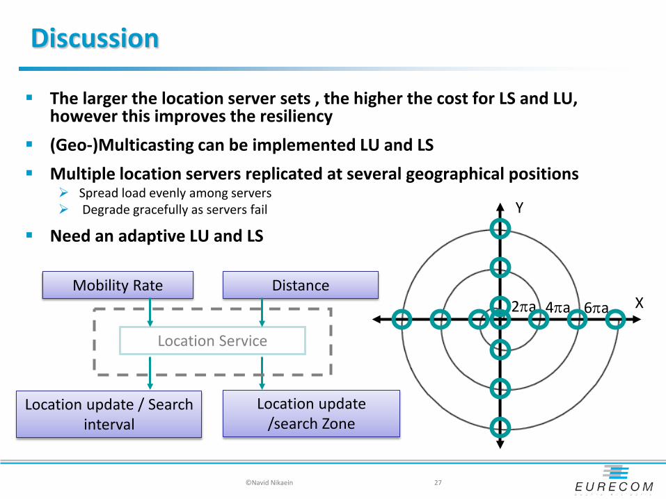
The larger the location server sets , the higher the cost for LS and LU, however this improves the resiliency
(Geo-)Multicasting can be implemented LU and LS Multiple location servers replicated at several geographical positions
Spread load evenly among servers Degrade gracefully as servers fail
Need an adaptive LU and LS
©Navid Nikaein 27
Mobility Rate Distance
Location Service
Location update / Search interval
Location update /search Zone
4πa 2πa 6πa
Y
X

Location Update/Search Parameters
Temporal resolution: frequency at which a location update/search is sent Timer-based: periodic, threshold (predictive) Distance-based: (velocity) location, threshold Profile, movement, state (a combination)
Spatial resolution: where/how far a location update/search should travel before it is discarded Blanket polling Shortest distance first Sequential (group) paging
©Navid Nikaein 28

Other issues
How to avoid empty location server
How to adjust the size of location server
What happens if no location reply is received?
Who determines the next hop? Sender or receiver
Location privacy?
©Navid Nikaein 29

Forwarding Strategy
To which node(s) should I forward packet P? Greedy forwarding: forwards P to exactly one neighbor closer
to the destination than the forwarding node itself Restricted directional flooding: forwards P to more than one
neighbor, e.g. DREAM, LAR Hierarchical forwarding: forwards P through a set of known
positions (e.g. anchor, location proxies) that lead to the final destination, e.g. Terminodes, Grid Apply topology-based routing (mainly proactive) for short distance
and position-based (mainly greedy) for long
©Navid Nikaein 32

Forwarding Strategy
To which node(s) should I forward packet P?
©Navid Nikaein 33
A C
D
F
S
M N
P
B
• Random Forward Progress: A/C/F • Most Forwarded within Radius: A • Nearest Forward Progress: N • Geographic distance: M • Nearest Closer: N • Compass (directional) routing: P
Are all of these approaches loop-free?

Concept of Progress
©Navid Nikaein 34
Compass • angle tuv is smallest
Greedy •Find v with min |vt| and |uv|<R
Random Compass with smallest angle either clockwise or couter-clockwise
Source: Wenzhan Song Farthest Neighbor Most Forwarding
Nearest Neighbor
Projection on the line connecting S to the destination

Geographic Distance Routing
GEDIR [Stoj99] : Each node forwards a packet to its neighbor with the closest geographical distance to the destination
The algorithm terminates when same edge traversed twice consecutively Node G is the neighbor of C who is closest from destination E, but C does not have a
route to E Local Maximum
©Navid Nikaein 35
S
A
B
D
C F E
obstruction
H
G
S
A
B
D
C F E
obstruction
H
G

Greedy Perimeter stateless routing
GPSR [karp00] Greedy forwarding
fast progress direct to destination Recovery
short progress, move around an obstacle
©Navid Nikaein 36
Optimal here Local maximum Recover mode
The optimality is to stay in greedy mode

Terminodes [blazovic00]
Combines topology- and position-based routing
Routing is done at two levels: Terminode local routing (TLR) : For short distance routing (# of
hops): route the packets according to a proactive distance vector algorithm Only 2 hop information
Terminode remote routing (TRR): For long term distance routing, a greedy forwarding is used Perimeter mode
Note: once the packet gets close to its final destination, it switches to the short distance routing
©Navid Nikaein 37
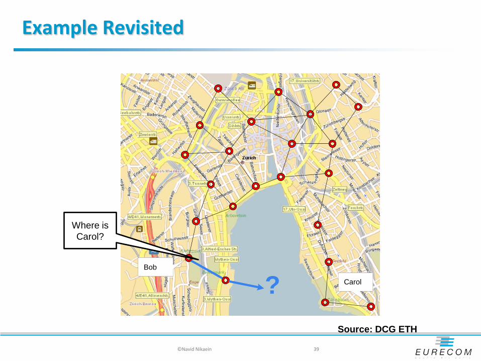
Example Revisited
©Navid Nikaein 39
Source: DCG ETH
Carol
Bob
?
Where is Carol?

Recovery Procedure
Deals with the situations where forwarding strategies may fail no one-hop neighbor closer to the destination than the forwarding
node itself Occurs in sparse networks or in presence of obstacle
Packet reaches a local maximum
Some Solutions: Local route discovery Closest neighbor or least negative backward
possibility of loop Reinitiate from source with a random selection of the forwarding
node Planner sub-graph
©Navid Nikaein 40

Recovery Mode: Terminodes
To prevent local maximum, the sender includes a list of anchor nodes into the header through which the packet should visit during forwarding Packet forwarding is greedy between two anchor nodes Could also be named as position-based source routing Note: the sender should know the sequence of anchor nodes that lead
to the final destination
©Navid Nikaein 41
A
AP2
S D
B

Make a Graph Planner
Convert a connectivity graph to planar non-crossing graph by removing “bad” edges Ensure the original graph will not be disconnected Two types of planar graphs:
Relative Neighborhood Graph (RNG) Gabriel Graph (GG)
©Navid Nikaein 42
Forwarding Recovery procedure
Forwarding fails
have left local maxima Forwarding works Forwarding fails

Recovery Mode: Planner Graphs
Drawn on the plane in such a way that no edges intersect • There is an edge between two
nodes u,v iff the disk(u,v) including boundary contains no other nodes
Localized using the position of neighbors
Forward the packet on faces of the planar subgraph Fails when links cross each other
©Navid Nikaein 43
U
V
x
y z
Face traversal without crossing edges

Recovery Mode: Planner Graphs
Face (Perimeter) traversal on a planar graph
Right hand rule and face changes forward the packet on the next
edge counterclockwise from the edge on which it arrived
Walking sequence: <F1-> F2 ->F3 ->F4>
©Navid Nikaein 44
Two primitives: (1) the right-hand rule (2) face-changes
X
F1
F2
F3
F4
Many existing algorithms like GFG, GPSR, GOAFR+, and etc. combine greedy traversal with face traversal.

Recovery Mode: Route on Face
Route along the boundaries of the faces that lie on the source–destination line Destination is reached in O(n) steps
©Navid Nikaein 45
1. Let F be the face incident to the source s, intersected by (s,d)
2. Explore the boundary of f; 3. Remember the point p where
the boundary intersects with (s,d) which is nearest to d;
4. after traversing the whole boundary, go back to p, switch the face
5. repeat 1 until you hit destination d
D S

Recovery Mode: Gabriel Graph
A Gabriel graph is a spanning subgraph of the original network Given any two adjacent nodes U
and V in the network Edge (U,V) belongs to the Gabriel
Graph (GG) iff no other node W is located in the disk with (U,V) as its diameter
Localized using the position of neighbours
©Navid Nikaein 46
V V
W
Important assumptions - Unit-disk graph & Accurate localization
- How well do planarization techniques work in real-world?
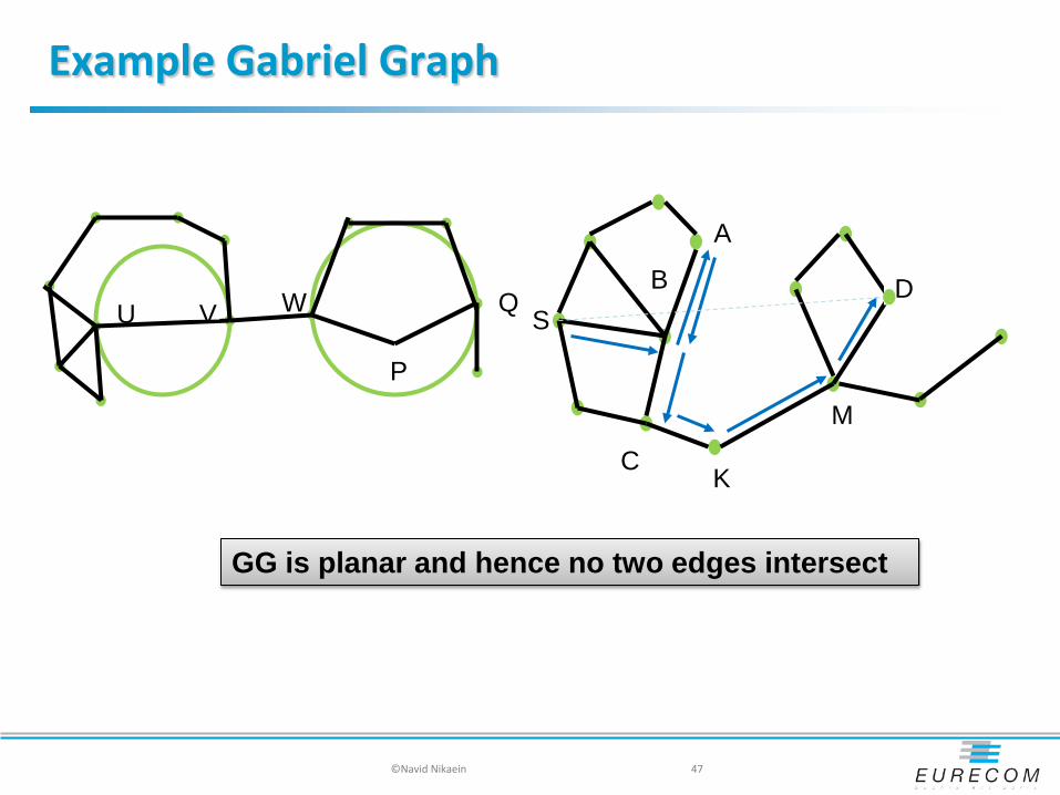
Example Gabriel Graph
©Navid Nikaein 47
U V W Q
P
GG is planar and hence no two edges intersect
S D
A
B
C K
M

Experimentation
©Navid Nikaein 48
Wireless Network Graph GG sub-graph
A test-bed deployed in UC Berkeley Soda Hall 50 MICA2dot, 433MHz radio, 5.2 average node density
Cross-link
Disconnected
Unidirectional √ 68.2% routing success among node pairs √ What’s happening?
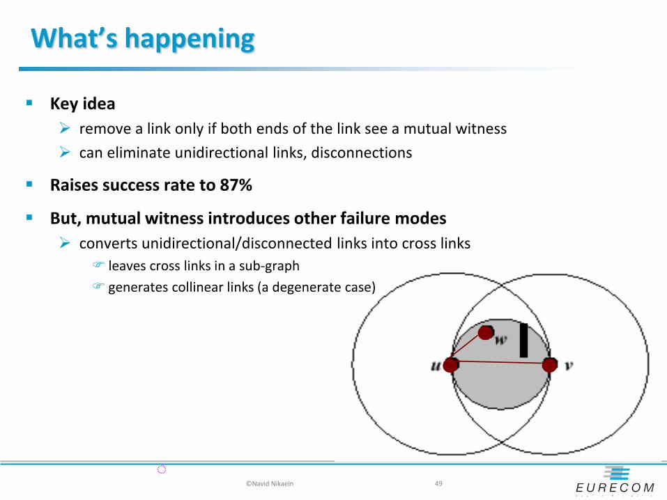
What’s happening
Key idea remove a link only if both ends of the link see a mutual witness can eliminate unidirectional links, disconnections
Raises success rate to 87%
But, mutual witness introduces other failure modes converts unidirectional/disconnected links into cross links
leaves cross links in a sub-graph generates collinear links (a degenerate case)
©Navid Nikaein 49
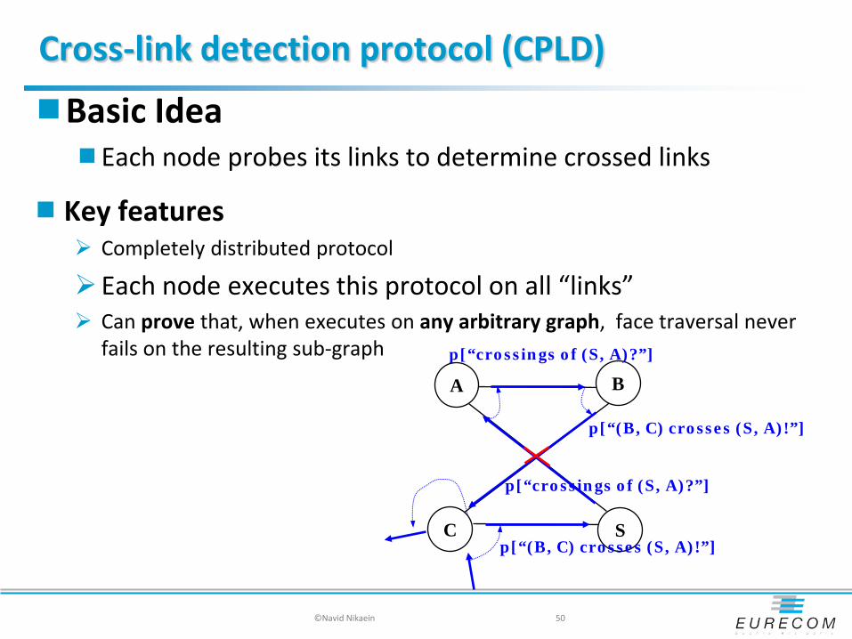
Cross-link detection protocol (CPLD)
Basic Idea Each node probes its links to determine crossed links
Key features Completely distributed protocol
Each node executes this protocol on all “links” Can prove that, when executes on any arbitrary graph, face traversal never
fails on the resulting sub-graph
©Navid Nikaein 50
A
S
B
C
p[“crossings of (S, A)?”]
p[“(B, C) crosses (S, A)!”]
p[“crossings of (S, A)?”]
p[“(B, C) crosses (S, A)!”]

Avoiding network partition
Solution keep a link if the probe returns on the link it was sent out on can leave cross-links in the sub-graph, but our proof shows that face traversal cannot fail on the sub-graph
©Navid Nikaein 51
A
S
B
C
case A case B
A
S
B
C
Network partition! Cross links!
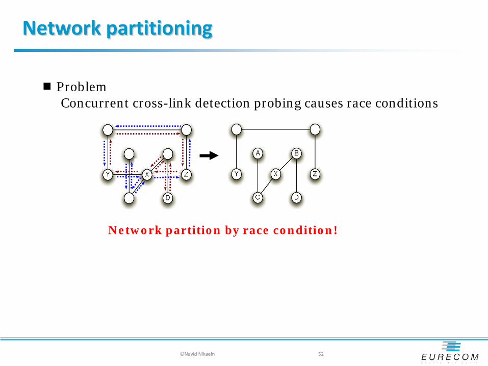
Network partitioning
©Navid Nikaein 52
Network partition by race condition!
Problem Concurrent cross-link detection probing causes race conditions

Experimental results
Radio graphs with obstacles
Random graphs
Metric: Success rate Stretch Overhead Convergence
©Navid Nikaein 53

Success rate
©Navid Nikaein 54
Radio graphs with 200 obstacles & 200 nodes
GPSR performs poorly due to partitions and unidirectional links

Stretch factor
©Navid Nikaein 55
Radio graph
GG subgraph
measured path length / shortest path length
GG planarization removes more links than CPLD

Worse case stretch ?
©Navid Nikaein 56
S D Right-hand rule
Worst case stretch – O(n), n : number of nodes
Worst case path length – O(nl), l : optimal path length
Position-based Routing
How far do I keep track of positions to my neighbors?
Do I keep track of positions to all destinations, or instead locating only those of immediate interests?
To which node(s) should I forward packet P?
How should I handle the local maximum?
©Navid Nikaein 57

Conclusion
Routing Problem Statement
Routing in wired networks
Tools and command to manipulate routing table
Taxonomy of Routing
Topology-based and position-based Routing
Experimental MANET Routing under IETF
Graph Theory, Algorithm and Protocols
Pseudo Algorithm, Flowchart, and State Machine
©Navid Nikaein 58