Embed Size (px)
Citation preview

Model�Based Object Pose in �� Lines of Code
Daniel F� DeMenthon and Larry S� Davis
Computer Vision LaboratoryCenter for Automation Research
University of MarylandCollege Park� MD �����
Abstract
In this paper� we describe a method for �nding the pose of an object from a single image� Weassume that we can detect and match in the image four or more noncoplanar feature pointsof the object� and that we know their relative geometry on the object� The method combinestwo algorithms� the �rst algorithm� POS �Pose from Orthography and Scaling approximatesthe perspective projection with a scaled orthographic projection and �nds the rotation matrixand the translation vector of the object by solving a linear system� the second algorithm�POSIT �POS with ITerations� uses in its iteration loop the approximate pose found byPOS in order to compute better scaled orthographic projections of the feature points� thenapplies POS to these projections instead of the original image projections� POSIT convergesto accurate pose measurements in a few iterations� POSIT can be used with many featurepoints at once for added insensitivity to measurement errors and image noise� Compared toclassic approaches making use of Newtons method� POSIT does not require starting froman initial guess� and computes the pose using an order of magnitude fewer �oating pointoperations� it may therefore be a useful alternative for real�time operation� When speed isnot an issue� POSIT can be written in � lines or less in Mathematica� the code is providedin an Appendix�
� Introduction
Computation of the position and orientation of an object �object pose� using images of featurepoints when the geometric con�guration of the features on the object is known �a modelhas important applications� such as calibration� cartography� tracking and object recognition�Fischler and Bolles ���� have coined the term Perspective�n�Point problem �or PnP problemfor this type of problem with n feature points�
Researchers have formulated closed form solutions when a few feature points are con�sidered in coplanar and noncoplanar con�gurations ��� �� ��� ��� ��� ���� However� pose
�

computations which make use of numbers of feature points larger than can be dealt within closed form solutions may be more robust because the measurement errors and imagenoise average out between the feature points and because the pose information content be�comes highly redundant� The most straightforward method� �rst described by Roberts �����consists of �nding the elements of the perspective projection matrix ���� � � ��� � which ex�presses the mapping between the feature points on the object and their image projectionsin homogeneous coordinates � as solutions of a linear system� The �� unknown elements inthis matrix can be found if at least six matchings between image points and object pointsare known� Also notable among pose computations are the methods proposed by Tsai �����Lowe ���� ���� and Yuan ���� �these papers also provide good critical reviews of photogram�metric calibration techniques� The methods proposed by Tsai are especially useful whenthe focal length of the camera� the lens distortion and the image center are not known�When these parameters have already been calibrated� the techniques proposed by Lowe andby Yuan may be su�cient� However� both techniques rely on the Newton�Raphson method�which presents two signi�cant drawbacks� �rst� an approximate pose must be provided toinitiate the iteration process� second� at each iteration step� the pseudoinverse matrix of aJacobian of dimensions �N � � �Lowe� N is the number of feature points or N � � �Yuanmust be found� a computationally expensive operation�
The method described in this paper relies on linear algebra techniques and is iterative likethe methods of Lowe and Yuan� but it does not require an initial pose estimate and does notrequire matrix inversions in its iteration loop� At the �rst iteration step� the method �nds anapproximate pose by multiplying an object matrix �which depends only on the distributionof feature points on the object and is precomputed by two vectors �which depend onlyon the coordinates of the images of these feature points� The two resulting vectors� oncenormalized� constitute the �rst two rows of the rotation matrix� and the norms of thesevectors are equal to the scaling factor of the projection� which provides the translationvector� We show that these operations amount to assuming that the involved image pointshave been obtained by a scaled orthographic projection �SOP in the following� We refer tothis part of the algorithm as �POS� �Pose from Orthography and Scaling� The works ofTomasi ���� and Ullman and Basri ���� apply related techniques �see also ���� for relatedwork with three points�
The next iterations apply exactly the same calculations� but with �corrected� imagepoints� The basic idea is that since the POS algorithm requires an SOP image instead ofa perspective image to produce an accurate pose� we have to compute SOP image points�using the pose found at the previous iteration� The process consists in shifting the featurepoints of the object in the pose just found� to the lines of sight �where they would belongif the pose was correct� and obtain a scaled orthographic projection of these shifted points�We call this iterative algorithm �POSIT� �POS with ITerations� Four or �ve iterations aretypically required to converge to an accurate pose�
The POSIT algorithm requires an order of magnitude fewer computations than the tech�niques mentioned above� For N matchings between object points and image points� POSITrequires around �� N arithmetic operations and two square root calculations per iteration�For � feature points and four iteration steps� around ��� arithmetic operations and � squareroots are needed� As a comparison� Roberts method would solve a linear system of �N
�

equations using a pseudoinverse matrix� which requires about ����N � ���� arithmetic op�erations �adds� multiplies and divides� for N � �� the total count is at least �� times morethan for POSIT� With Lowes method� for each iteration� around ���N � � operationsare required� for � feature points and four iteration steps� the total count of arithmeticoperations is around �� times more than POSIT� Yuans method seems to be the most ex�pensive� with around ��N� � ��N� arithmetic operations to set up the iteration loop� then��N� � ���N � ��� operations at each iteration� for eight feature points and four iterationsteps� the total count of operations is around � times more than for POSIT�
Based on these comparisons� we believe that the proposed method has de�nite advantagesover previous approaches for real�time applications�
In later sections of this paper� we test the accuracy and stability of the method byconsidering a large set of simulated situations with increasing amounts of random imageperturbation �� �� In all these situations� the algorithm appears to remain stable and todegrade gracefully as image noise is increased�
� Notations
In Fig� �� we show the classic pinhole camera model� with its center of projection O� itsimage plane G at a distance f �the focal length from O� its axes Ox and Oy pointing alongthe rows and columns of the camera sensor� and its third axis Oz pointing along the opticalaxis� The unit vectors for these three axes are called i� j and k �vectors are written in boldcharacters�
An object with feature points M��M�� � � � �Mi� � � � �Mn is positioned in the �eld of viewof the camera� The coordinate frame of reference for the object is centered at M� and is�M�u�M�v�M�w� We call M� the reference point for the object� Only the object pointsM� and Mi are shown in Fig� �� The shape of the object is assumed to be known� thereforethe coordinates �Ui� Vi�Wi of the point Mi in the object coordinate frame of reference areknown� The images of the points Mi are called mi� and their image coordinates �xi� yi areknown� The coordinates �Xi� Yi� Zi of the same points Mi in the camera coordinate systemare unknown� because the pose of the object in the camera coordinate system is unknown�We next show how to �nd the rotation matrix and translation vector of the object directly�without solving explicitly for the coordinates �Xi� Yi� Zi�
� Problem De�nition
Our goal is to compute the rotation matrix and translation vector of the object� The rotationmatrixR for the object is the matrix whose rows are the coordinates of the unit vectors i� j�kof the camera coordinate system expressed in the object coordinate system �M�u�M�v�M�w�Indeed� the purpose of the rotation matrix is to transform the object coordinates of vectorssuch as M�Mi into coordinates de�ned in the camera system� the dot product M�Mi� ibetween the �rst row of the matrix and the vector M�Mi correctly provides the projectionof this vector on the unit vector i of the camera coordinate system� i�e� the coordinateXi�X� of M�Mi� as long as the coordinates of M�Mi and of the row vector i are expressedin the same coordinate system� here the coordinate system of the object�
�
m0
O
C
H
Miz
xi
k
mi
w
u
M0
v
j
K
G
y
PiNi
pi
Z0
f
Figure �� Perspective projection �mi and scaled orthographic projection �pi for an objectpoint Mi and a reference point M��
�

The rotation matrix can therefore be written as
R �
���
iu iv iwju jv jwku kv kw
���
where iu� iv� iw are the coordinates of i in the coordinate system �M�u�M�v�M�w of theobject�
To compute the rotation� we only need to compute i and j in the object coordinate system�The vector k is then obtained by the cross�product i � j� The translation vector� T is thevectorOM� between the center of projection� O� and the reference pointM�� the origin of theobject coordinate frame of reference� Therefore the coordinates of the translation vector areX�� Y�� Z�� If this point M� has been chosen to be a visible feature point for which the imageis a point m�� this translation vector T is aligned with vector Om� and is equal to Z�
fOm��
Therefore to compute the object translation� we only need to compute its z�coordinate Z��Thus the object pose is fully de�ned once we �nd i� j and Z��
� Scaled Orthographic Projection and Perspective Projection
��� Analytical De�nition
Scaled orthographic projection �SOP is an approximation to �true� perspective projection�In this approximation� for a given object in front of the camera� one assumes that the depthsZi of di�erent points Mi of the object with camera coordinates �Xi� Yi� Zi are not verydi�erent from one another� and can all be set to the depth of one of the points of the object�for example the depth Z� of the reference point M� of the object �see Fig� �� In SOP� theimage of a point Mi of an object is a point pi of the image plane G which has coordinates
x�i � fXi�Z�� y�i � fYi�Z��
while for perspective projection an image point mi would be obtained instead of pi� withcoordinates
xi � fXi�Zi� yi � fYi�Zi
The ratio s � f�Z� is the scaling factor of the SOP� The reference pointM� has the same im�agem� with coordinates x� and y� in SOP and perspective projection� The image coordinatesof the SOP projection pi can also be written as
x�i � fX��Z� � f�Xi �X��Z� � x� � s�Xi �X�
y�i � y� � s�Yi � Y� ��
��� Geometric Construction of SOP
The geometric construction for obtaining the perspective image point mi of Mi and the SOPimage point pi of Mi is shown in Fig� �� Classically� the perspective image point mi is the

intersection of the line of sight of Mi with the image plane G� In SOP� we draw a plane Kthrough M� parallel to the image plane G� This plane is at a distance Z� from the center ofprojection O� The point Mi is projected on K at Pi by an orthographic projection� ThenPi is projected on the image plane G at pi by a perspective projection� The vector m�pi isparallel to M�Pi and is scaled down from M�Pi by the scaling factor s equal to f�Z�� Eq� �simply expresses the proportionality between these two vectors�
� Fundamental Equations for Perspective
We now consider equations that characterize �true� perspective projection and relate theunknown row vectors i and j of the rotation matrix and the unknown Z� coordinate of thetranslation vector to the known coordinates of the vectors M�Mi in the object coordinatesystem� and to the known coordinates xi and yi of the image points m� and mi� Solvingthese equations for these unknowns would provide all the information required to de�ne theobject pose� as we have seen in Section �� These equations are
M�Mi�f
Z�i � xi�� � �i� x�� ��
M�Mi�f
Z�j � yi�� � �i� y� ��
in which the terms �i are de�ned as
�i ��
Z�M�Mi�k ��
and k is de�ned as k � i� j
Proof� In Fig� �� consider points M�� Mi of the object� and the plane K parallel to theimage plane through M�� The line of sight for Mi intersects plane K in Ni� and Mi projectsonto plane K in Pi� The vector M�Mi is the sum of three vectors
M�Mi �M�Ni �NiPi �PiMi �
The vector M�Ni and its image m�mi are proportional in the ratio Z��f � The two vectorsNiPi and Cmi are also proportional in the two similar triangles CmiO and NiPiMi� in aratio equal to the ratio of the z coordinates of the other two corresponding vectors of thesetriangles� PiMi and OC� This ratio is M�Mi�k�f � The sum of the three vectors can thenbe expressed as
M�Mi �Z�
fm�mi �
M�Mi�k
fCmi �PiMi ��
We take the dot product of this expression with the unit vector i of the camera coordinatesystem� The dot product PiMi� i is zero� the dot product m�mi� i is the x�coordinate�xi � x�� of the vector m�mi� the dot product Cmi� i is the coordinate xi of Cmi� With thede�nition �i �
�Z�
M�Mi�k� one obtains Eq� �� Similarly� one obtains Eq� � by taking thedot product of expression � with unit vector j �
�

� Fundamental Equations and POS
We now show that in the right hand sides of the fundamental equations� the terms xi��� �iand yi�� � �i� are in fact the coordinates x�i and y�i of the points pi� which are the scaledorthographic projections of the feature points Mi �Fig� ��
Consider the points M�� Mi� the projection Pi of Mi on the plane K� and its image pi�We call the coordinates of pi in the image plane x�i and y�i� The vector M�Mi is the sum oftwo vectors M�Pi and PiMi� The �rst vector� M�Pi� and its image m�pi are proportionalin the ratio Z��f � Consequently�
M�Mi �Z�
fm�pi �PiMi
We take the dot product of this vector with unit vector i of the camera coordinate system�the dot product PiMi� i is zero� and the dot product m�pi� i is the x coordinate� x�i � x�� ofthe vector m�pi� We obtain
M�Mi�f
Z�i � x�i � x� ��
and similarly
M�Mi�f
Z�j � y�i � x�� ��
Comparing these equations with Eqs� � and �� one sees that the coordinates of pi can bewritten x�i � xi�� � �i and y�i � yi�� � �i�
� POS and POSIT
The equations � and � can also be written
M�Mi� I � xi�� � �i� x�� ��
M�Mi�J � yi�� � �i� y�� ���
with
I �f
Z�i� J �
f
Z�j
The basic idea behind the proposed method is that if values are given to �i� Eqs� �and �� provide linear systems of equations in which the only unknowns are respectively thecoordinates of I and J� Once I and J have been computed� i are j are found by normalizingI and J� and Tz is obtained from the norm of either I or J� We call this algorithm� which�nds the pose by solving linear systems� POS �Pose from Orthography and Scaling� Indeed��nding the pose of the object by using �xed values of �i in Eq� � and � amounts to �ndingthe pose for which the points Mi have as scaled orthographic projections the image pointspi with coordinates xi�� � �i and yi�� � �i� as we have seen in the previous section�
The solutions of the POS algorithm are only approximations if the values given to �i arenot exact� But once the unknowns i and j have been computed� more exact values can be
�

computed for the �i� and the equations can be solved again with these better values� Wecall this iterative algorithm POSIT �POS with Iterations� This algorithm generally makesthe values of i� j and Z� converge toward values which correspond to a correct pose in a fewiterations�
Initially� we can set �i � �� Assuming �i null implies x�i � xi� y�
i � yi and amountsto assuming that pi and mi coincide� Fig� � describes this con�guration� Note from thede�nition of the terms �i �Eq� � that they are the z�coordinates of vectors between twoobject points� divided by the distance of the object to the camera� these ratios are smallwhen the ratio of object size to distance is small� so that the pose found at the very �rstiteration may be acceptable in this case� When tracking an object� the initial values for theterms �i are preferably chosen equal to the values obtained at the last iteration of the posecomputation for the previous image�
������������������������������������������������������������
�����������������������������������������������������������������
O
C
H
Miz
xi
k
w
u
v
j
K
G
yf
Z0
M0
m0
mi
Pi
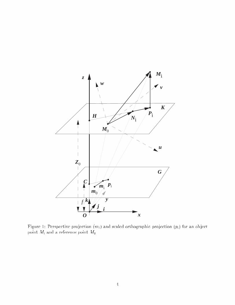
Figure �� The initial loop in POSIT looks for a pose of the object such that the points mi
are the scaled orthographic projections of the points Mi of the object�
�

Solving the Systems of Equations POS algorithm�
Within the iterative algorithm described in the previous section� we have to solve Eqs� � and��� We rewrite these equations in a somewhat more compact form
M�Mi� I � �i�
M�Mi�J � �i�
with
I �f
Z�i� J �
f
Z�j� �i � xi�� � �i� x�� �i � yi�� � �i� y��
and where the terms �i have known values computed at the previous iteration steps of thealgorithm� We express the dot products of these equations in terms of vector coordinates inthe object coordinate frame of reference�
�Ui Vi Wi��Iu Iv Iw�T � �i� �Ui Vi Wi��Ju Jv Jw�
T � �i�
where the T exponent expresses the fact that we consider a transposed matrix� here a columnvector� These are linear equations where the unknowns are the coordinates of vector I andvector J� The other parameters are known� xi� yi� x�� y� are the known coordinates of mi andm� �images of Mi and M� in the camera coordinate system� and Ui� Vi�Wi are the knowncoordinates of the point Mi in the object coordinate frame of reference�
Writing Eq� � for the n object points M��M��Mi� � � � �Mn and their images� we generatelinear systems for the coordinates of the unknown vectors I and J�
AI � x�� AJ � y� ���
where A is the matrix of the coordinates of the object points Mi in the object coordinateframe of reference� x� is the vector with i�th coordinate �i and y� is the vector with i�thcoordinate �i� Generally� if we have at least three visible points other than M�� and all thesepoints are noncoplanar� matrix A has rank �� and the solutions of the linear systems in theleast square sense are given by
I � Bx�� J � By� ���
where B is the pseudoinverse of the matrix A�
We call B the object matrix� Knowing the geometric distribution of feature points Mi�we can precompute this pseudoinverse matrix B� either by the operation �ATA���AT � or bydecomposing matrix A by Singular Value Decomposition �SVD ����� One can �nd in ���� adiscussion showing that the solutions computed by Eq� �� for the systems of Eq� �� indeedminimize the norms of the residual vectors jAI � x�j and jAJ � y�j� The Singular ValueDecomposition has the advantage of giving a clear diagnosis about the rank and conditionof matrix A� this is useful in photogrammetric applications� when one has to make surethat the feature points on the terrain can be considered noncoplanar before applying thisalgorithm �for an extension of this algorithm to coplanar points using a matrix A of rank ��see �����
�

Once we have obtained least square solutions for I and J� the unit vectors i and j aresimply obtained by normalizing I and J� As mentioned earlier� the three elements of the �rstrow of the rotation matrix of the object are then the three coordinates of vector i obtainedin this fashion� The three elements of the second row of the rotation matrix are the threecoordinates of vector j� The elements of the third row are the coordinates of vector k ofthe z�axis of the camera coordinate system and are obtained by taking the cross�product ofvectors i and j�
Now the translation vector of the object can be obtained� It is vector OM� between thecenter of projection� O� and M�� the origin of the object coordinate system� This vectorOM�� is aligned with vector Om� and is equal to Z�Om��f � i�e� Om��s� The scaling factors is obtained by taking the norm of vector I or vector J� as can be seen from the de�nitionsof these vectors in terms of i and j provided with Eqs� � and ���
If the �i terms used in Eqs� � and �� are accurate� the rotation matrix and translationmatrix just computed can be considered accurate representations of the pose� otherwise�they can be used to compute more accurate values for �i� and then the process is repeated�as will be explained below in greater details�
� Geometric Interpretation for the System Solutions
Geometrically� Eq� � states that if the tail of I is taken to be at M�� the head of I projectson M�Mi at a point Hxi de�ned by the algebraic measure
M�Hi �x�i
jM�Mij
In other words� the head of I must belong to the plane perpendicular to M�Mi at Hi� If weuse four feature points�M��M��M��M�� and these points are chosen to be noncoplanar� thenI is completely de�ned as the vector with its tail at M� and its head at the intersection ofthe three planes perpendicular to M�M�� M�M� and M�M� at H�� H� and H� respectively�Analytically� we solve a system of three equations� and the matrix of the system has rank ��We would use as matrix B the inverse of matrix A instead of its pseudoinverse�
If more than four feature points are used� the corresponding planes generally do notintersect exactly at a single point� but we would like to choose as head of I the point whichminimizes the sum of the squares of its distances to these planes� Analytically� the systemof equations is overdetermined� the matrix of the system of equations is still of rank �� andthe solution in the least square sense is obtained by using the pseudoinverse B of the matrixA in Eq� ���
� Pseudocode for the POSIT Algorithm
We can now summarize the description of the POSIT algorithm for N feature points �in�cluding the reference point M� with the following pseudocode
� Step � �preliminary step� executed once for a set of simultaneously visible featurepoints�
��
Write the matrix A with dimension �N � � � �� each row vector is a vector M�Mi
connecting the reference feature point M� to another feature point Mi� compute the�� �N � � object matrix B as the pseudoinverse matrix of A�
� Step �� �i��� � �� �i � ����N � �� n � ��
� Step �� beginning of loop�Compute i� j� and Z��
� Compute the image vector x� with N�� coordinates of the form xi����i�n����x��and the image vector y� with N � � coordinates of the form yi�� � �i�n���� y��
� Multiply the ���N�� object matrixB and the image vectors �N�� coordinatesto obtain vectors I and J with � coordinates� I � Bx� and J � By��
� Compute the scale s of the projection as the average between the norms of I andJ� s� � �I� I���� s� � �J�J���� s � �s� � s����
� Compute unit vectors i and j� i � I�s�� j � J�s��
� Step �� Compute new �i�
� Compute unit vector k as the cross�product of i and j�
� Compute the z�coordinate Z� of the translation vector as Z� � f�s where f isthe camera focal length�
� Compute �i�n� ��Z�
M�Mi�k�
� Step �� If j�i�n� � �i�n���j �Threshold� n � n� �� Go to Step ��
� Step � Else output pose using values found at last iteration� the full translation vectorOM� is OM� � Om��s� the rotation matrix is the matrix with row vectors i� j and k�for applications where the rotation matrix must be perfectly orthonormal� renormalizethis matrix� compute k� � k�jkj� j� � k� � i� and output the matrix with row vectorsi� j�� and k��
� �� Geometric Interpretation of the Algorithm
The iterative algorithm described analytically in the previous section can also be describedgeometrically as follows�
� Step � �preliminary step� compute object matrixB as the pseudoinverse matrix of A�
� Step �� Assume that the scaled orthographic projections pi of Mi are superposed withthe image points mi of Mi � pi��� � mi�
� Steps �� Compute an approximate pose assuming that the projection model is a scaledorthographic projection�
��

� Step �� Shift the object points from their found approximate positions to positions atthe same depth but on their lines of sight �a deformation of the object�Find the images of these shifted points by a scaled orthographic projection model�
� Step �� If these scaled orthographic image points are not the same as those found atprevious iteration� go back to Step � using these image points instead of the originalimage points�
� Step � Else� exact pose � last approximate pose�
Proof� Our goal here is to show that the steps of the geometric description of the algorithmare equivalent to the analytic description provided by the pseudocode�
Steps � and �� As we have seen in Section �� �nding the pose using Eqs� � and � withcalculated values for �i �analytical description amounts to �nding the pose for which thepointsMi project in points pi with coordinates xi����i and yi����i by a scaled orthographicprojection �geometric description� At step �� assuming �i to be zero �analytical descriptionimplies x�i � xi� y
�
i � yi and amounts to assuming that pi and mi coincide �Fig���
Step �� Object pointsMi are shifted to the lines of sight of the original image pointsmi atconstant depth� then projected into points pi by a scaled orthographic projection �geometricdescription� The coordinates of pi for these shifted points Mi are xi����i and yi����i� aswe have just seen� with �i �
�Z�
M�Mi�k �Eq� ��This dot product and the term Z� are nota�ected by the shift of Mi in a direction perpendicular to the vector k� thus the terms �i canbe obtained without accounting for this shift� simply by multiplying the M�Mi � de�nedonce and for all in the object reference frame � by the vector k de�ned in the same frame�which is the third row of the rotation matrix �analytical description�
Step �� Once the �i terms dont change from one iteration to the next �analytic de�scription� the expressions for the coordinates of the points pi dont change �geometric de�scription� One or the other test can be used� With the geometric description� no arti�cialthreshold needs to be introduced for the de�nition of change� one exits the loop once thequantized positions of the points pi �in pixels stop moving� �
�� An intuitive interpretation of the POSIT algorithm
The process by which an object pose is found by the POSIT algorithm can be seen from athird� somewhat more intuitive� viewpoint�
� What is known is the distribution of the feature points on the object and the imagesof these points by perspective projection�
� If we could build SOP images of the object feature points from a perspective image�we could apply the POS algorithm to these SOP images and we would obtain an exactobject pose�
� Computing exact SOP images requires knowing the exact pose of the object� However�we can apply POS to the actual image points� we then obtain an approximate depth
��

for each feature point� and we position the feature points on the lines of sight at thesedepths� Then we can compute an SOP image� At the next step we apply POS tothe SOP image to �nd an improved SOP image� Repeating these steps� we convergetoward an accurate SOP image and an accurate pose�
�� Deformation Measure
The POS algorithm uses at least one more feature point than is strictly necessary to �nd theobject pose� At least four noncoplanar points including M� are required for this algorithm�whereas three points are in principle enough if the constraints that i and j be of equal lengthand orthogonal are applied ����� Since we do not use these constraints in POS� we can verifya posteriori how close the vectors i and j provided by POS are to being orthogonal and ofequal length� Alternatively� we can verify these properties with the vectors I and J� sincethey are proportional to i and j with the same scaling factor s� We construct a deformationmeasure G� for example as
G � jI � Jj� jI � I� J � Jj
The POSIT algorithm �nds the translation vector and the transformation matrix that trans�form the object onto the camera coordinate system so that its feature points fall on the linesof sight of the image points� The transformation matrix may not exactly be an orthonormalrotation matrix� but may comprise a deformation component which slightly deforms theobject to adjust it to the lines of sight� The deformation measure G is zero if the transfor�mation matrix is a rotation matrix� The deformation measure G generally becomes large�of course� when the wrong correspondence has been established between image points andobject points� therefore we have used this measure to solve the correspondence problemwhen only a small number of correspondence ambiguities exist� applying the POS algorithmwith various correspondence permutations and choosing the correspondence permutationthat yields the minimum deformation measure as a preliminary step before completing thePOSIT algorithm �see also ��� for a systematic analysis of this type of approach�
What are possible causes for �nding a nonzero deformation measure when the correctcorrespondence permutation is used� In the ideal case of an object at the correct pose and noimage noise� Eqs� � and � would be exactly veri�ed� Returning to the geometric interpretationof Section �� the planes perpendicular to M�Mi at points Hxi de�ned at abscissae �xi�� ��i � x��jM�Mij would exactly meet at a single point� the head of I corresponding tothis correct pose� and the planes perpendicular to M�Mi at points Hyi de�ned at abscissae�yi�� � �i� y��jM�Mij would exactly meet at the head of J corresponding to this correctpose� For these two vectors the deformation measure would be zero� During the iterationprocess of the POSIT algorithm� the terms �i are �rst set to zero� then computed until theyreach the values corresponding to the correct pose� Accordingly� the points Hxi and Hyi areinitially di�erent from the correct points� and move toward these points during the iteration�Thus initially the planes do not generally cut at single points� and there is little chance thatthe vectors I and J found at the minimum added squared distance between these planes canbe equal and perpendicular� and the resulting deformation measure is not zero� As the pointsHxi and Hyi move toward their correct positions at successive iteration steps� the resultingdeformation measure tends to zero�
��
The scenario assumes perfect image detection and camera modelizing� In practice� thecoordinates xi and yi are not the coordinates of the ideal geometric perspective projectionsof the Mi� and the planes obtained at convergence generally do not meet at single points�Therefore the �nal deformation measure is generally not zero �during the iteration it mayeven go through a value slightly smaller than its �nal value� accordingly� the �nal resultingmatrix is not exactly orthogonal� but comprises a deformation component which slightlywarps the object so that it better �ts the noisy image and the assumed camera model� Formost applications� an orthonormal transformation matrix is more useful� The output matrixis easily corrected� for instance by normalizing the vector k obtained by the cross�productof i and j� then replacing j by the cross�product of k and i�
�� Illustration of the Iteration Process in POSIT
We can illustrate the iteration process of POSIT with an example using synthetic data�The object is a cube �cube size �� cm� image �� � ��� focal length ��� pixels� cornersof the cubes are at a distance between three and four times the cube size from the centerof projection of the camera� The cube is assumed transparent� and the feature points arethe corners of the cube� We use a full cube in this experiment without simulating hiddenfaces� because it is interesting to see the converging projections of the parallel edges in theperspective image being transformed into parallel projections in the SOP image �in fact itis not di�cult to do actual experiments with eight corners of a cube� using light emittingdiodes mounted in a cubic arrangement on a transparent frame�
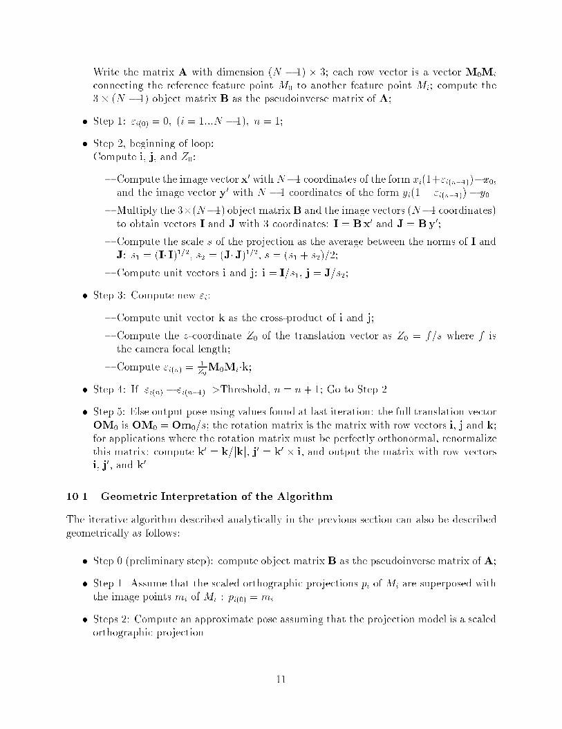
The projection on the left of Fig� � is the given perspective image for the cube� Theenclosing square is the boundary of the �� � �� pixel image area� The projections of thecube edges which are drawn on the �gure are not used by the algorithm� but are usefulfor studying the evolution of the scaled orthographic projections of the cube� Because thedistance�to�size ratio for the cube is small� some cube edges show a strong convergence inthe image� One can get an idea of the success of the POSIT algorithm by computing at eachiteration the perspective image of the cube for the transformation found at this iteration�The three projections at the top of Fig� � are such perspective projections at three iterations�Note that from left to right� these projections are getting closer and closer to the originalimage� POSIT does not compute these images� Instead� POSIT computes SOP images usingonly the actual image corners and the depths it computed for the corners� These images areshown on the bottom row of Fig� �� Notice that� from left to right� the images of the cubeedges become more and more parallel� an indication that the algorithm is getting closer tothe correct scaled orthographic projection of the cube� in which parallel lines project ontoparallel image lines�
�� Protocol of Performance Characterization
In this section� we attempt to follow the recommendations of Haralick for performance eval�uation in computer vision �� �� We compute the orientation and position errors of the POSalgorithm at the �rst iteration loop �an approximation whihc assumes that the perspective
��
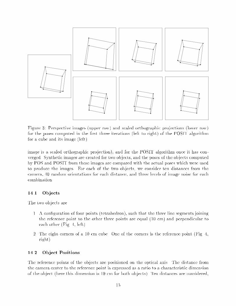
Figure �� Perspective images �upper row and scaled orthographic projections �lower rowfor the poses computed in the �rst three iterations �left to right of the POSIT algorithmfor a cube and its image �left�
image is a scaled orthographic projection� and for the POSIT algorithm once it has con�verged� Synthetic images are created for two objects� and the poses of the objects computedby POS and POSIT from these images are compared with the actual poses which were usedto produce the images� For each of the two objects� we consider ten distances from thecamera� �� random orientations for each distance� and three levels of image noise for eachcombination�
���� Objects
The two objects are
�� A con�guration of four points �tetrahedron� such that the three line segments joiningthe reference point to the other three points are equal ��� cm and perpendicular toeach other �Fig� �� left
�� The eight corners of a �� cm cube� One of the corners is the reference point �Fig� ��right�
���� Object Positions
The reference points of the objects are positioned on the optical axis� The distance fromthe camera center to the reference point is expressed as a ratio to a characteristic dimensionof the object �here this dimension is �� cm for both objects� Ten distances are considered�
�

���������������������������
z
O
C
x
G
yfD
ista
nce
to C
amer
a
Random Rotations
���������������������������
z
O
C
x
G
y
Object Size
f
Random Rotations
Object Size
Dis
tanc
e to
Cam
era
Figure �� De�nition of objects and parameters used for estimating rotation and translationerrors of the POSIT algorithm�
from four times to �� times the object size� These distance�to�size ratios are used as thehorizontal coordinates on all the orientation and position error plots�
Around each of these reference point positions� the objects are rotated at �� randomorientations� The rotation matrices de�ning these �� orientations are computed from threeEuler angles chosen by a random number generator in the range ��� ���
���� Image Generation
We obtain images by perspective projection with a focal length of ��� pixels� Here we do notclip the image� in order to allow for large o�sets of the images� When the reference point ofthe cube is �� cm from the image plane on the optical axis and when the cube is completelyon one side of the optical axis� the point at the other end of the diagonal of the cube maybe �� cm from the image plane and have an image � pixels from the image center� Onlya wide�angle camera with a total angular �eld of more than � degrees would be able to seethe whole cube in this position�
We specify three levels of random perturbation and noise in the image� At noise level ��the real numbers computed for the coordinates of the perspective projections are rounded tointeger pixel positions� At noise level �� the integer positions of the lowest level are disturbedby vertical and horizontal perturbations of � � pixel around the integer positions� Theseare created by a uniform random number generator� At noise level �� the amplitude of theperturbations are � � pixels� When the objects are at ��� cm from the camera� the imagemay be as small as �� pixels� and a perturbation of two pixels on each side of the imageproduces a ��� perturbation in image size�
��

4 8 12 16 20 24 28 32 36 40
2
4
6
8
10
4 8 12 16 20 24 28 32 36 40
2
4
6
8
10
4 8 12 16 20 24 28 32 36 40
2
4
6
8
10
4 8 12 16 20 24 28 32 36 40
2
4
6
8
10
4 8 12 16 20 24 28 32 36 40
2
4
6
8
10
Orie
ntat
ion
Err
or, d
egre
esO
rient
atio
n E
rror
, deg
rees
Orie
ntat
ion
Err
or, d
egre
esO
rient
atio
n E
rror
, deg
rees
Orie
ntat
ion
Err
or, d
egre
es
Distance to Camera / Object Size
Distance to Camera / Object SizeDistance to Camera / Object Size
Distance to Camera / Object SizeDistance to Camera / Object Size
Higher Points: POSLower Points: POSIT
Higher Points: POSLower Points: POSIT
Higher Points: POSLower Points: POSIT
Higher Points: POSLower Points: POSIT
Higher Points: POSLower Points: POSIT
Tetrahedron Image with Quantization
Tetrahedron Image with ± 1 Pixel Perturbations
Cube Image with Quantization
Cube Image with ± 1 Pixel Perturbations
Cube Image with ± 2 Pixel PerturbationsTetrahedron Image with ± 2 Pixel Perturbations
4 8 12 16 20 24 28 32 36 40
2
4
6
8
10
����������
Orie
ntat
ion
Err
or, d
egre
es
Distance to Camera / Object Size
Higher Points: POSLower Points: POSIT�
Figure � Angular orientation errors for a tetrahedron�left and for a cube �right for ��distances from the camera� with three image noise levels �quantization� �� pixel� �� pixels�
��

4 8 12 16 20 24 28 32 36 40
0.02
0.04
0.06
0.08
0.1
Distance to Camera / Object SizeDistance to Camera / Object Size
Distance to Camera / Object SizeDistance to Camera / Object Size
Distance to Camera / Object SizeDistance to Camera / Object Size
Higher Points: POSLower Points: POSIT
Higher Points: POSLower Points: POSIT
Higher Points: POSLower Points: POSIT
Higher Points: POSLower Points: POSIT
Higher Points: POSLower Points: POSIT
Higher Points: POSLower Points: POSIT
4 8 12 16 20 24 28 32 36 40
0.02
0.04
0.06
0.08
0.1
4 8 12 16 20 24 28 32 36 40
0.02
0.04
0.06
0.08
0.1
4 8 12 16 20 24 28 32 36 40
0.02
0.04
0.06
0.08
0.1
4 8 12 16 20 24 28 32 36 40
0.02
0.04
0.06
0.08
0.1
4 8 12 16 20 24 28 32 36 40
0.02
0.04
0.06
0.08
0.1
Rel
ativ
e P
ositi
on E
rror
Rel
ativ
e P
ositi
on E
rror
Rel
ativ
e P
ositi
on E
rror
Rel
ativ
e P
ositi
on E
rror
Rel
ativ
e P
ositi
on E
rror
Rel
ativ
e P
ositi
on E
rror
Tetrahedron Image with Quantization
Tetrahedron Image with ± 1 Pixel Perturbations
Cube Image with Quantization
Cube Image with ± 1 Pixel Perturbations
Cube Image with ± 2 Pixel PerturbationsTetrahedron Image with ± 2 Pixel Perturbations
Figure �� Relative position errors for a tetrahedron�left and for a cube �right for �� dis�tances from the camera� with three image noise levels �quantization� �� pixel� �� pixels�
��
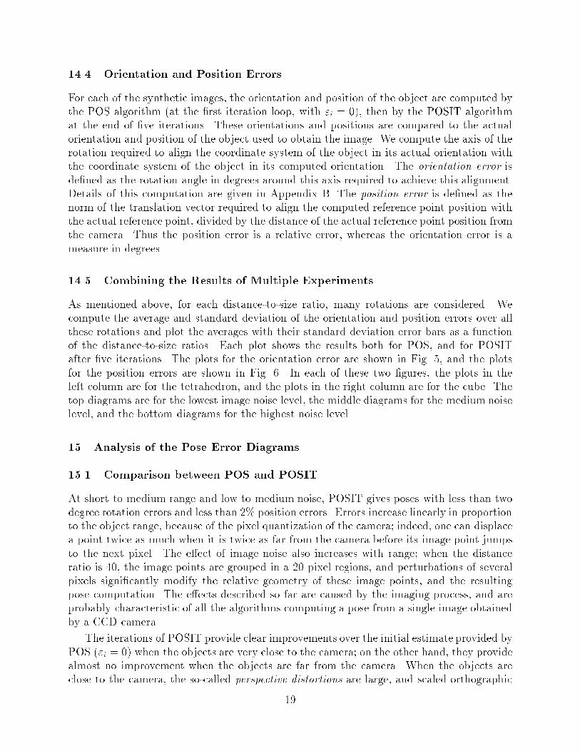
���� Orientation and Position Errors
For each of the synthetic images� the orientation and position of the object are computed bythe POS algorithm �at the �rst iteration loop� with �i � �� then by the POSIT algorithmat the end of �ve iterations� These orientations and positions are compared to the actualorientation and position of the object used to obtain the image� We compute the axis of therotation required to align the coordinate system of the object in its actual orientation withthe coordinate system of the object in its computed orientation� The orientation error isde�ned as the rotation angle in degrees around this axis required to achieve this alignment�Details of this computation are given in Appendix B� The position error is de�ned as thenorm of the translation vector required to align the computed reference point position withthe actual reference point� divided by the distance of the actual reference point position fromthe camera� Thus the position error is a relative error� whereas the orientation error is ameasure in degrees�
���� Combining the Results of Multiple Experiments
As mentioned above� for each distance�to�size ratio� many rotations are considered� Wecompute the average and standard deviation of the orientation and position errors over allthese rotations and plot the averages with their standard deviation error bars as a functionof the distance�to�size ratios� Each plot shows the results both for POS� and for POSITafter �ve iterations� The plots for the orientation error are shown in Fig� � and the plotsfor the position errors are shown in Fig� �� In each of these two �gures� the plots in theleft column are for the tetrahedron� and the plots in the right column are for the cube� Thetop diagrams are for the lowest image noise level� the middle diagrams for the medium noiselevel� and the bottom diagrams for the highest noise level�
�� Analysis of the Pose Error Diagrams
���� Comparison between POS and POSIT
At short to medium range and low to medium noise� POSIT gives poses with less than twodegree rotation errors and less than �� position errors� Errors increase linearly in proportionto the object range� because of the pixel quantization of the camera� indeed� one can displacea point twice as much when it is twice as far from the camera before its image point jumpsto the next pixel� The e�ect of image noise also increases with range� when the distanceratio is ��� the image points are grouped in a �� pixel regions� and perturbations of severalpixels signi�cantly modify the relative geometry of these image points� and the resultingpose computation� The e�ects described so far are caused by the imaging process� and areprobably characteristic of all the algorithms computing a pose from a single image obtainedby a CCD camera�
The iterations of POSIT provide clear improvements over the initial estimate provided byPOS ��i � � when the objects are very close to the camera� on the other hand� they providealmost no improvement when the objects are far from the camera� When the objects areclose to the camera� the so�called perspective distortions are large� and scaled orthographic
��

projection is a poor approximation of perspective� therefore the performance of POS is poor�For the shortest distance�to�size ratio ��� errors in orientation evaluation are in the �� degreeregion� and errors in position evaluation are in the ��� region� When the objects are very far�there is almost no di�erence between SOP and perspective� This can be seen analytically�the terms �i in Eq� � are negligible when the objects are far� so that the perspective equationsbecome identical to the SOP equations� Thus POS gives the best possible results� and theiterations of POSIT cannot improve upon them� POS gives its best performance for distancesaround �� times the object size for low image noise� and around �� times for high imagenoise � half way between the large errors of perspective distortion at short distances andthe large errors of pixel quantization at large distances � with orientation errors in the threedegree region and position level in the �� region�
���� Comparison between Cube and Tetrahedron
The long error bars at short range for POS seem to be due to the fact that the apparentimage size can be very di�erent depending on the orientation� For example� the cube lookslike an object of size �� cm when a face is parallel to the image plane� but one dimension is��� larger when a cube diagonal is parallel to the image plane� In this last con�guration�the reference point projects at the image center whereas the opposite corner is o�centeredby more than ��� pixels� with a large resulting perspective distortion� The tetrahedron doesnot have as large apparent size changes� which may explain the fact that at short viewingdistance the average error and standard deviation produced by POS are smaller for thisshape than for the cube� This is more an artifact of the problem of de�ning object size witha single number than a speci�c advantage of the tetrahedron over the cube�
At high noise level and long range� the performance with the cube becomes almost twiceas good as with the tetrahedron for POS and POSIT� probably because the least squaremethod averages out the random errors on the points� and the averaging improves whenmore points are made available to the method�
�� Convergence Analysis for POSIT
With the distance�to�size ratios used in the rotation and translation error evaluations above�the POSIT algorithm would converge in four or �ve iterations� The convergence test usedhere consists of quantizing �in pixels the coordinates of the image points in the SOP imagesobtained at successive steps� and terminating when two successive SOP images are identical�see Appendix A�
One can apply POSIT with �D images of a �D world� and in this case one can analy�tically show that the quantities determining the algorithms convergence are ratios of imagecoordinates over focal length� i�e� tangents of the angles between the optical axis and thelines of sight� When all the ratios are smaller than �� the algorithm converges� The featurepoints are then seen with a view angle of less than � degrees� Therefore with a camera witha �� degree total �eld of view� the algorithm would converge for all possible image points�When all the view angles are more than � degrees� the algorithm diverges� Thus with anobject with all its image points at the periphery of the �eld of a ��� degree camera the
��

algorithm would diverge� In mixed situations with small and large angles� mixed results areobtained� image points close to the image center contribute to convergence� and balance thenegative e�ect of peripheral image points�
A mathematical analysis of the conditions of convergence in the more interesting casewhen POSIT is applied to �D images in a �D world has eluded us so far� however� insimulations� convergence appears to be similarly dependent on the angles of the lines ofsight� A cube is displaced along the camera optical axis �Fig� �� One face is kept parallel tothe image plane� because at the shorter ranges being considered� the cube cannot be rotatedmuch without intersecting the image plane� The distance used to calculate the distance�to�object size ratio in the plots is the distance from the center of projection to the cube� Noiseof �� pixels is added to the perspective projection� For a cube of �� cm� four iterations arerequired for convergence until the cube is �� cm from the center of projection� The numbergradually climbs to eight iterations as the cube reaches �� cm from the center of projection�and �� iterations for cm� Then the number increases sharply to ��� iterations for a distanceof ��� cm from the center of projection� In reference to our prior �D observations� at thisposition the images of the close corners are more than two focal lengths away from the imagecenter� but the images of the far corners are only half a focal length away from the imagecenter and probably contribute to preserving the convergence�
Up to this point the convergence is monotonic� At still closer ranges the mode of con�vergence changes to a nonmonotonic mode� in which SOP images of successive steps seemsubjected to somewhat random variations from step to step until they hit close to the �nalresult and converge rapidly� The number of iterations ranges from �� to �� in this mode�i�e� less than for the worse monotonic case� with very di�erent results for small variations ofobject distance� We label this mode �chaotic convergence� in Fig� �� Finally� when the cubegets closer than ��� cm away from the center of projection� the di�erences between imagesincrease rapidly and the algorithm clearly diverges� Note� however� that in order to see theclose corners of the cube at this range a camera would require a total �eld of more than� � degrees� i�e� a focal length of less than �� mm for a �� mm CCD chip� an improbablecon�guration� This preliminary convergence analysis and the simulations of the previoussection indicate that for ordinary cameras� the POSIT algorithm seems to converge withoutproblems in a few iterations�
We know� however� that some speci�c con�gurations of noncoplanar feature points havebeen shown to produce ambiguous images for some isolated positions of the object� Herewe call the image ambiguous when distinct poses of the object in space can produce thesame image with the same correspondences� In other words� once we have found a rigidtransformation that positions each of the feature points on a line of sight of an image point�a second rigid transformation could be found that moves each feature point to anotherposition on the same line of sight� Examples of such con�gurations can be found in �����The POSIT algorithm for a noncoplanar con�guration of points produces a single pose�If the feature points on the object happen to be located in space in a con�guration thatproduces an ambiguous image� the POSIT algorithm will compute only one of the possibleposes� and there are good chances that this pose may not be the one occupied by theobject� We note in our defense that numerical algorithms relying on the Newton�Raphsonmethod ���� ��� ��� do not behave di�erently in this case� On the other hand� Roberts
��

0.5 1 1.5 2 2.5 3 3.5 40
20
40
60
80
100
Num
ber
of It
erat
ions
0.1 0.2 0.3 0.40
20
40
60
80
100
Divergence
Num
ber
of It
erat
ions
Distance to Camera / Object Size
MonotonicConvergence
Chaotic Convergence Monotonic
Convergence
Distance to Camera / Object Size
Figure �� Number of iterations for POSIT as a function of distance to camera� Top� De�ni�tion of distance and object size� Middle� Convergence results at very short ranges� Conver�gence occurs if the �� cm cube is more than ��� cm away from the camera� Bottom� Numberof iterations for a wider range of distances�
method �nds the perspective projection matrix which maps world points to image pointsexpressed with homogeneous coordinates� For ambiguous images� this mapping is not unique�and this fact can be detected by the fact that the matrix of the linear system used in thismethod is singular� Therefore� Roberts method seems preferable for applications in whichdetecting pathological con�gurations is important� An analysis of the geometry of suchcon�gurations can be found in ���� ���� For an ambiguous image to occur� the object pointsand the cameras center of projection must belong to the same twisted cubic curve in space�Such a curve is de�ned by six points� therefore one can make sure that the event will nothappen by choosing as feature points seven object points that cannot all belong to the samecubic curve� When fewer points are considered� ambiguous images can occur but probablyremain unlikely� When the POSIT algorithm is used in tracking a moving object using fewerpoints� one can in principle detect the fact that the algorithm has computed the wrong posefrom an ambiguous image by noticing a discontinuity in the sequence of poses�
��
�� Real�Time Experiments
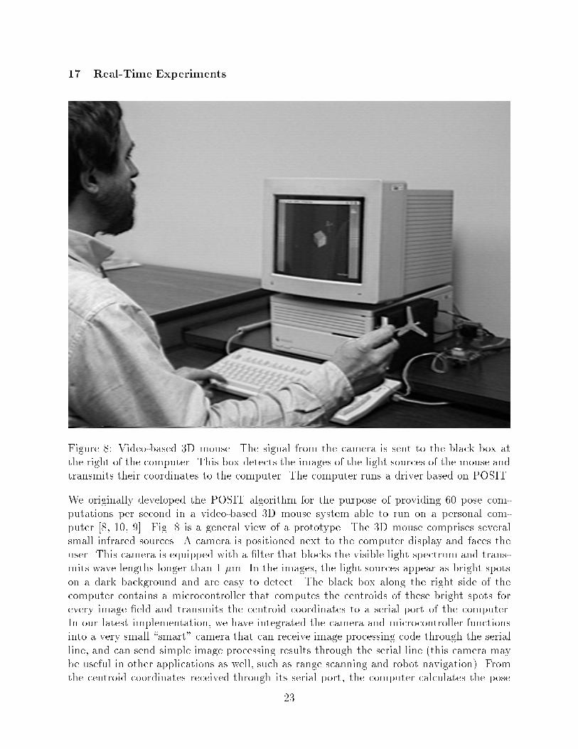
Figure �� Video�based �D mouse� The signal from the camera is sent to the black box atthe right of the computer� This box detects the images of the light sources of the mouse andtransmits their coordinates to the computer� The computer runs a driver based on POSIT�
We originally developed the POSIT algorithm for the purpose of providing �� pose com�putations per second in a video�based �D mouse system able to run on a personal com�puter ��� ��� ��� Fig� � is a general view of a prototype� The �D mouse comprises severalsmall infrared sources� A camera is positioned next to the computer display and faces theuser� This camera is equipped with a �lter that blocks the visible light spectrum and trans�mits wave lengths longer than � �m� In the images� the light sources appear as bright spotson a dark background and are easy to detect� The black box along the right side of thecomputer contains a microcontroller that computes the centroids of these bright spots forevery image �eld and transmits the centroid coordinates to a serial port of the computer�In our latest implementation� we have integrated the camera and microcontroller functionsinto a very small �smart� camera that can receive image processing code through the serialline� and can send simple image processing results through the serial line �this camera maybe useful in other applications as well� such as range scanning and robot navigation� Fromthe centroid coordinates received through its serial port� the computer calculates the pose
��

of the �D mouse �� times per second� and computes the corresponding perspective image ofa �D cursor� which is displayed on the screen� This �D cursor allows an intuitive interactionwith �D objects represented on the screen�
We �nd that the pose calculation itself does not create any problems� provided thematching between object light sources and image spots is correct� We have used for themouse alignments of light sources which can be easily detected and matched in the image�Alternatively� we have used a tetrahedron of four light sources arranged so that the linesegments between one source and the three others are equal and mutually perpendicular�This con�guration simpli�es the pose calculation� because the object matrix B is then a � �� identity matrix� With this mouse� we choose the matching which minimizes a combinationof the deformation measure of Section �� and the di�erence from the previous pose� Thematching is nontrivial in some conditions� In particular� with the tetrahedron con�guration�one can often �nd two matchings which would correspond to two poses which are symmetricwith respect to a plane parallel to the image plane� When the two poses are close together�it is di�cult to choose the better pose� If the user never attempts to point the mousetoward himself �a maneuver which has a good chances of resulting in the hand occluding alight source anyway� then one pose can be rejected� Also� image spots are very often closetogether� and the matching may be di�cult in these conditions too� When image spots getcloser� they may end up merging� and when this occurs a single centroid is detected� Wekeep track of the assignements of spots that are close together� so that when they merge�we can assign the same image centroid to two line sources� With these precautions� weobtain a reasonably robust and usable system in which the �D cursor responds smoothlyand predictably to the rotations and translations of the �D mouse in space� Details aboutthis system can be found in ����
From these experiments� it seems to us that with a fast algorithm such as POSIT� avideo�based approach may be an attractive alternative in the growing �eld of interactive�D graphics� where both mechanical� magnetic� acoustic and optical pose trackers are beingdeveloped �����
� Summary and Discussion
We have presented an algorithm� POSIT� that can compute the pose of an object froman image containing several noncoplanar feature points of the object� We have describedin pseudocode form the steps required for the computation� explaining the role of eachstep from both analytical and geometrical points of view� The algorithm �rst computes anapproximate pose by a method �POS which assumes that the image was obtained by ascaled orthographic projection� This step multiplies a precomputed object matrix and twoimage vectors� normalizes the resulting vectors� then computes a cross�product to completethe rotation matrix� it then multiplies a vector by the norm used in the normalization justmentioned to obtain the translation vector� The next step of the POSIT algorithm computes�corrected� image points using scaled orthographic projections based on the approximateobject pose found at the previous step� These two steps are repeated until no improvementis detected� Simulations show that the algorithm converges in a few iterations in the domainof useful con�gurations of a camera and an object� We have characterized the performance
��

of the algorithm by a number of experiments on synthetic data with increasing levels ofimage noise� The POSIT algorithm appears to remain stable and to degrade gracefully withincreasing image noise levels�
POSIT may be a useful alternative to popular pose algorithms because of the followingadvantages�
�� It does not require an initial pose estimate�
�� Its code is easy to implement� In compact languages such as Mathematica� only around� lines of code are necessary �Appendix A�
�� It can run ten times faster than those algorithms� since it typically requires an orderof magnitude fewer arithmetic operations�
One of the objections that may be raised is that since POSIT does not make full useof the fact that the rotation matrix is orthonormal� it is bound to be less accurate thanalgorithms that account for this fact� This is probably the case when the minimum numberof feature points �� is considered� but the di�erence should disappear as the number ofpoints is increased and the pose information available in the image becomes more redundant�Comparative experiments would be useful in deciding about this issue� If indeed somealgorithms are shown to provide an advantage in accuracy� and if the considered applicationrequires such additional accuracy� the advantages of POSIT mentioned above may still makeit useful for producing an initial pose for these algorithms�
Before going to such lengths� one has to remember that there are intrinsic limitationson pose calculation from single images that no algorithm using single images may be ableto overcome� For example� object displacements in the direction of the optical axis movethe feature points more or less along the lines of sight �more so as the object size�distancedecreases� so that rather large object displacements can occur before they translate intojumps to neighboring pixels in the image� Methods using line features ���� would have thesame problems in detecting these displacements� In some applications� it is possible to obtaingreater accuracy by combining the information obtained from two cameras with optical axesat a large angle �ideally �� degrees� at the expense of added complexity in calibration andcomputation�
In photogrammetric applications� the feature points are often coplanar or almost copla�nar� In these situations� the method described in this paper must be signi�cantly modi�ed�because the matrix A describing the positions of the feature points in the scene has rank ��This extension of the POSIT algorithm to planar scenes is described in �����
Finally� assigning the proper correspondence between object points and their images isa required preliminary step for the POSIT algorithm� this problem has been addressed onlybrie�y� In Section ��� we suggest that the algorithm be run for di�erent point correspon�dences� and that the correct correspondence corresponds to the minimal deformation factor�In our �D mouse experiments �Section ��� we have combined this technique with com�parisons between successive pose solutions to produce robust correspondence assignments�this is a feasible technique only if a few correspondence permutations have to be examined�Methods which do not depend exponentially on the number of points and combine the search
�
for the correct pose and the search for the correct correspondence have been proposed ��� ��we �nd that the search is painfully slow because it takes place in a high�dimensional trans�formation space� For these methods to become attractive� novel criteria for further pruningthe search tree will have to be discovered�
Acknowledgements
We thank Thor Bestul for valuable discussions� and Azriel Rosenfeld for his comments onearlier drafts of this paper� we also express our thanks to the three reviewers for very usefulinsights� which led us in particular to develop the analytical formulation of POSIT� Thesupport of the Defense Advanced Research Agency under Contract DACA������C����� isgratefully acknowledged� A shorter version of this paper considering only the geometricinterpretation of the algorithm was published in the Proceedings of the ���� EuropeanConference on Computer Vision ����
Appendix A� A Mathematica program implementing POS and POSIT
Compute the pose of an object given a list of �D image points� a list of corresponding �Dobject points� and the object matrix �the pseudoinverse matrix for the list of object points�The �rst point of the image point list is taken as a reference point� The outputs are the posecomputed by POS using the given image points and the pose computed by POSIT�
GetPOSIT�imagePoints��objectPoints��objectMatrix��focalLength���� Module�
�objectVectors� imageVectors� IVect� JVect� ISquare� JSquare� IJ�
imageDifference� row�� row�� row� scale�� scale�� scale� oldSOPImagePoints�
SOPImagePoints� translation� rotation� count � � converged � False��
objectVectors � � �objectPoints������� �� objectPoints�
oldSOPImagePoints�imagePoints�
�� loop until difference between � SOP images is less than one pixel ��
While�� converged�
If�count���
�� we get image vectors from image of reference point for POS� ��
imageVectors � Map�� � imagePoints�������� imagePoints��
�� else count�� we compute a SOP image first for POSIT� ��
SOPImagePoints � imagePoints����objectVectors�row��translation������
imageDifference � Apply�Plus� Abs�Round�Flatten�SOPImagePoints���
Round�Flatten�oldSOPImagePoints�����
oldSOPImagePoints � SOPImagePoints�
imageVectors � Map�� � SOPImagePoints�������� SOPImagePoints�
�� �� end else count���
�IVect� JVect� � Transpose�objectMatrix � imageVectors��
ISquare � IVect�IVect� JSquare � JVect�JVect� IJ � IVect�JVect�
�scale�� scale�� � Sqrt��ISquare� JSquare���
�row�� row�� � �IVect�scale�� JVect�scale���
row � RotateLeft�row�� RotateRight�row�� �
RotateLeft�row�� RotateRight�row����� cross�product ��
��

rotation��row�� row�� row��
scale � �scale� � scale������ �� scaling factor in SOP ��
translation � Append�imagePoints������ focalLength��scale�
converged � �count�� �� �imageDifference����
count��
�� �� End While ��
Return��rotation� translation���
�� Example of input and output� ��
focLength � ���
cube ��������������������������������
�����������������������
cubeMatrix � PseudoInverse�cube���N�
cubeImage � �������������������������������������
������������ ��������� ������
�POSITRot�POSITTrans� �
GetPOSIT�cubeImage� cube� cubeMatrix� focLength�
Out��� � �������� ������ ������
��������� ������� ������
�������� ������� ���������
�� � �������
Appendix B� Angular Error
In our performance evaluation� the object has a coordinate system in a known orientation�and the POS and POSIT algorithms compute from the image of the object a coordinatesystem that is in a di�erent orientation� We want to compute how far o� the computedorientation is from the actual orientation� We �nd the axis of the rotation required to alignthe coordinate system of the object in its actual orientation with the coordinate system ofthe object in its computed orientation� The angular error is the rotation angle in degreesaround this axis required to achieve this alignment� The axis of rotation and the angle forthe alignment can be readily found with quaternions� but we propose a more direct methodhere� Given the two unit vectors i and i� of the x�axes of the two coordinate systems� the axisof rotation must belong to a plane with respect to which i and i� are mirror images of eachother� Therefore this plane is perpendicular to the vector i� � i� Similarly� the axis belongsto the plane perpendicular to j� � j and to the plane perpendicular to k� � k� Thus the axismust have a direction n perpendicular to both i�� i� j�� j and k�� k� The coordinates of nsatisfy the homogeneous system composed of the equation
�i�x � ixnx � �i�y � iyny � �i�z � iznz � �
��

and two similar equations in j� � j and k� � k� This system is solved by Singular ValueDecomposition� Then the required angle of the rotation is the angle which brings the plane�n� i to the plane �n� i�� i�e� the angle between the cross product n� i and the cross productn� i�� The angle between �n� j and �n� j� and the angle between �n�k and �n�k� may beslightly di�erent� thus we compute the average of these three angles�
References
��� Abidi� M� A�� T� Chandra� �A New E�cient and Direct Solution for Pose EstimationUsing Quadrangular Targets� Algorithm and Evaluation�� Dept� of Electrical and Com�puter Engineering� The University of Tennessee� July ��� to be published in IEEE Trans�on Pattern Analysis and Machine Intelligence�
��� Basri� R� and D� Weinshall� �Distance Metric between �D Models and �D Images forRecognition and Classi�cation�� MIT A�I� Memo No� ����� �����
��� Breuel� T� M�� �Fast Recognition using Adaptive Subdivisions of Transformation Space��Proc� IEEE Conf� on Computer Vision and Pattern Recognition� Champaign� IL� pp��� �� �� �����
��� DeMenthon� D� F�� �De la Vision Arti�cielle a la R!ealit!e Synth!etique� Syst emedinteraction avec un ordinateur utilisant lanalyse dimages vid!eo�� Doctoral Thesis�Universit!e Joseph Fourier � Grenoble I� Laboratoire TIMC�IMAG� October �����
� � DeMenthon� D� F�� �Recognition and Tracking of �D Objects by �D Search�� Proc�ARPA Image Understanding Workshop� Washington� DC� pp� � ��� �� �����
��� DeMenthon� D� F� and L� S� Davis� �New Exact and Approximate Solutions of the Three�Point Perspective Problem�� IEEE Trans� on Pattern Analysis and Machine Intelligence�vol� ��� pp� �������� � �����
��� DeMenthon� D� F� and L� S� Davis� �Model�Based Object Pose in � Lines of Code��Computer Vision�ECCV ��� Lecture Notes in Computer Science ��� G� Sandini �Ed��pp� �� ����� Springer�Verlag� �����
��� DeMenthon� D� F�� �Computer Vision System for Position Monitoring in Three Dimen�sions using Non�Coplanar Light Sources Attached to a Monitored Object�� U�S� Patent ������� � June ��� ���� �Application ���������� August ����
��� DeMenthon� D� F�� and Y� Fujii �Three Dimensional Pointing Device Monitored byComputer Vision�� U�S� Patent ��������� March ���� �Application ���������� May�����
���� DeMenthon� D� F�� �Computer Vision System for Accurate Monitoring of Object Pose��Patent Application ���������� December �����
��

���� Dhome� M�� M� Richetin� J� T� Lapreste� and G� Rives� �Determination of the Attitudeof �D Objects from a Single Perspective View�� IEEE Trans� on Pattern Analysis andMachine Intelligence� vol� ��� pp� ��� ������ �����
���� Egli� W� H�� J� W� Miller� J� M� Setterholm� �Method and Apparatus for DeterminingLocation and Orientation of Objets�� U�S� Patent � ��� ��� June �����
���� Faugeras� O���Three�Dimensional Computer Vision � a Geometric ViewPoint�� MITPress� ����
���� Fischler� M� A�� and R� C� Bolles� �Random Sample Consensus� A Paradigm for ModelFitting with Applications to Image Analysis and Automated Cartography�� Comm�ACM� vol� ��� pp� ������ � �����
�� � Haralick� R�M�� �Performance Characterization in Computer Vision�� University ofWashington C�S� Technical Report� July ����� also �Performance Characterization inImage Analysis� Thinning� a Case in Point�� Pattern Recognition Letters� vol� ��� pp� ���� �����
���� Horaud� R�� B� Conio and O� Leboulleux� �An Analytical Solution for the Perspective���Point Problem�� Computer Vision� Graphics� and Image Processing� vol� ��� pp� �����������
���� Huttenlocher and D�� S� Ullman� �Recognizing Solid Objects by Alignment�� Proc�DARPA Image Understanding Workshop� pp� ����������� �����
���� Lowe� D� G�� �Perceptual Organization and Visual Recognition�� Kluwer AcademicPublishers� ��� �
���� Lowe� D� G�� �Fitting Parameterized Three�Dimensional Models to Images�� IEEETrans� on Pattern Analysis and Machine Intelligence� vol� ��� pp� ����� �� �����
���� Maybank� S�J�� �The Projective Geometry of Ambiguous Surfaces�� Phil� Trans� R� Soc�Lond� A ���� pp� ����� �����
���� Meyer� K�� H� L� Applewhite� anf F� A� Biocca� �A Survey of Position Trackers�� Pres�ence� vol� �� pp� �������� Spring �����
���� Oberkampf� D�� D� F� DeMenthon� and L� S� Davis� �Iterative Pose Estimation usingCoplanar Feature Points�� IEEE Conf� on Computer Vision and Pattern Recognition�pp� �������� New York� ����� full version� Center for Automation Research TechnicalReport CAR�TR����� University of Maryland� July �����
���� Press� W� H�� B� P� Flannery� S� A� Teukolsky� and W� T� Veterling� Numerical Recipesin C� Cambridge University Press� Cambridge� UK� �����
���� Roberts� L�G� �Machine Perception of Three�Dimensional Solids�� in Optical and Elec�trooptical Information Processing� J� Tippet et al�� eds�� MIT Press� ��� �
��

�� � Sutherland� I�E� �Three�Dimensional Input by Tablet�� Proceedings of the IEEE� vol����pp� � �����������
���� Tomasi� C�� �Shape and Motion from Image Streams� A Factorization Method�� Tech�nical Report CMU�CS�������� Carnegie Mellon University� September �����
���� Tsai� R�Y�� �A Versatile Camera Calibration Technique for High�Accuracy �D MachineVision Metrology Using O��the�Shelf TV Cameras and Lenses�� IEEE J� Robotics andAutomation� vol� �� pp� �������� �����
���� Ullman� S�� and R� Basri� �Recognition by Linear Combinations of Models�� IEEETrans� on Pattern Analysis and Machine Intelligence� vol� ��� pp� ��������� �����
���� Yuan� J�S�C�� �A General Photogrammetric Method for Determining Object Positionand Orientation�� IEEE Trans� on Robotics and Automation� vol� � pp� �������� �����
��


![UNIT t 2 Ob ject Modelling Tec hn ique Unit-02/Lecture- 01 · UNIT t 2 Ob ject Modelling Tec hn ique Unit-02/Lecture- 01 System desi gn life cycle [RGPV /DEC-2010( 10 )] Goal s The](https://img.dokumen.tips/doc/110x75/5e7995c9d13b4e17f02f12a8/unit-t-2-ob-ject-modelling-tec-hn-ique-unit-02lecture-01-unit-t-2-ob-ject-modelling.jpg)

![A Mo del of Concurrency in Ob ject-Orien ted Databases · 2002. 2. 19. · ct-oriente d datab ase management. On tos, V ersan t, Ob ject Design and others [25] in tro duced C++ libraries](https://img.dokumen.tips/doc/110x75/61408a6c2e263e64232a2122/a-mo-del-of-concurrency-in-ob-ject-orien-ted-2002-2-19-ct-oriente-d-datab-ase.jpg)