Embed Size (px)
Citation preview
MOORINGMAINTENANCE
MANUAL
NAVFAC MO-124AUGUST 1987
SN 0525-LP-173-1115

NAVY : SNDLD i s t r i b u t i o n
E3AFA6FA7FA10FA18FA30FB10FB13FB21FB34FC5FC7FC12FB48FKA1CFKA8F5FKN1FKN2FKN3FKN5FKQ6BFKP1BFKP1EFKP739G139G239E139E2
2 c o p i e s u n l e s s o t h e r w i s e s t a t e d .
WASHINGTON ONLYBERMUDA AND SIGONELLA ONLYLESS KEFLAVIK
NAVACTS UK AND NAVACT DET HOLY LOCH ONLY
LA MADDALENA ONLYDIEGO GARCIA ONLY25 COPIESKINGS BAY ONLY25 COPIES (NORTHNAVFACENGCOM 2 ONLY)
5 COPIESPANAMA CITY ONLYCHARLESTON, EARLE AND SEAL BEACH ONLY
PUGET SOUND ONLY10 COPIES10 COPIES
COPY TO: 1 COPY EACH
21A39B139B2
A d d i t i o n a l c o p i e s m a y b e o b t a i n e d f r o m :U. S. NAVAL PUBLICATIONS AND FORMS CENTER5801 TABOR AVENUEPHILADELPHIA, PA 19120

ABSTRACT
The Commander, Naval Facilities Engineering Command (COMNAVFAC-
ENGCOM) has the overall responsibility for the budgeting, funding, procuring,
installing, operating, and maintaining of fleet moorings worldwide. To support him
in the control and management of these worldwide systems, this manual has been
prepared for use by subordinate units. It contains a compendium of procedures to
be followed in maintaining mooring material in suitable condition for use by
operational fleet surface vessels and submarines. It additionally contains numerous
illustrations and photographs of mooring material and inspection, maintenance,
and storage procedures.
i
FOREWORD
This manual contains background information and procedural guidelines
concerning the maintenance of Navy fleet moorings and spare fleet mooring
material. This includes mooring installation and recovery procedures, the
refurbishing and overhaul of mooring material ashore and afloat, inspection
criteria and guidelines, inventory storage criteria, and the utilization of cathodic
protection systems to effectively reduce the corrosion rate of mooring material.
The materials and procedures detailed herein have been prepared to assist the
user in establishing and sustaining an effective fleet mooring maintenance
program. Although it is not mandatory that field units follow the recommended
procedures, they have been developed from the best technical sources available to
the Naval Facilities Engineering Command (NAVFACENGCOM) and represent many
years of practical and successful field experience.
Recommendations for modification or improvement of this document should
be submitted through appropriate channels to the Naval Facilities Engineering
Command.
Rear Admiral, U.S. Navy
Commander, Naval Facilities
Engineering Command
ii
TABLE OF CONTENTS
Page
ABSTRACT
FOREWORD
LIST OF FIGURES
LIST OF TABLES
1.0
1.1
1.1.1
1.1.2
1.1.3
1.1.4
1.1.5
1.1.6
1.1.7
1.1.8
1.2
1.2.1
1.2.2
1.2.3
1.2.4
1.2.5
1.2.6
1.2.7
2.0
2.1
2.1.1
2.1.2
2.1.3
2.1.4
2.1.5
2.1.6
2.1.7
2.1.8
INTRODUCTION
GENERAL
SCOPE
PURPOSE
EXCLUSIONS
RELATED PUBLICATIONS
PROGRAM RESPONSIBILITY
PLANNING, PROGRAMMING, AND BUDGETING
REPORTING REQUIREMENTS
FLEET MOORING MAINTENANCE
DESCRIPTION
GENERAL
TYPES OF FLEET MOORINGS
UPGRADED MOORINGS
MOORING CLASSIFICATIONS
MAJOR FLEET MOORING ASSEMBLIES
TYPES OF BUOY SYSTEMS
MOORING COMPONENTS
MOORING INSTALLATION AND RECOVERY
PREPARATION
GENERAL
PLANNING AND PREPARATION
TOOLS AND EQUIPMENT REQUIRED
PRE-INSTALLATION LAYOUT
PRE-INSTALLATION POSITIONING
PRE-INSTALLATION INSPECTION
FIELD CHANGES OF DESIGN
AS-BUILT DRAWINGS
I
ii
vii
ix
1
1
1
1
1
2
2
3
4
5
7
7
7
12
12
14
14
15
16
16
16
16
17
17
18
20
20
20
iii
TABLE OF CONTENTS (Continued)
Page
2.2
2.2.1
2.2.2
2.3
2.3.1
3.0
3.1
3.1.1
3.1.2
3.1.3
3.1.4
3.2
3.2.1
3.2.2
3.2.3
3.2.4
3.2.5
4.0
4.1
4.1.1
4.1.2
4.2
4.2.1
4.2.2
4.2.3
4.2.4
4.2.5
5.0
5.1
5.1.1
5.1.2
INSTALLATION INSTRUCTIONS
GENERAL
RISER-TYPE MOORING SYSTEM
RECOVERY INSTRUCTIONS
RISER-TYPE MOORING SYSTEM
INSPECTIONS
GENERAL
OVERALL REQUIREMENTS
INSPECTION CLASSIFICATIONS AND TYPES
PURPOSE
PERSONNEL
INSPECTION PROCEDURES
GENERAL
ANNUAL SURFACE INSPECTIONS
UNDERWATER INSPECTIONS
LIFT INSPECTIONS
MOORING DAMAGE/FAILURE INSPECTIONS
IN-SERVICE MAINTENANCE AND REPAIR
GENERAL
SCOPE
EQUIPMENT
PROCEDURES
BUOY REPLACEMENT (RISER-TYPE)
RISER REPLACEMENT
BUOY REPLACEMENT (NON-RISER-TYPE)
MINOR REPAIRS
BUOY COATINGS
ASHORE INSPECTION AND REFURBISHMENT OF BUOYS
GENERAL
SCOPE
PREPARATION FOR ASHORE INSPECTIONS
22
22
22
29
29
34
34
34
34
34
35
35
35
35
38
38
40
42
42
42
42
42
42
43
44
44
46
47
47
47
47
iv

TABLE OF CONTENTS (Continued)
Page
5.2
5.2.1
5.2.2
5.3
5.3.1
5.3.2
5.4
5.4.1
5.4.2
5.4.3
5.4.4
5.4.5
6.0
6.1
6.1.1
6.2
6.2.1
6.2.2
6.2.3
7.0
7.1
7.1.1
7.2
7.2.1
7.2.2
7.2.3
8.0
8.1
8.1.1
8.1.2
8.1.3
INSPECTION PROCEDURES
PRELIMINARY INSPECTION
DETAILED INSPECTION
BUOY REPAIRS AND MODIFICATIONS
GENERAL
PROCEDURES
PROTECTIVE COATINGS
PREPARATION FOR APPLICATION
FOAM FILLED ELASTOMER COVERED BUOYS
FIBERGLASS POLYESTER RESIN (FPR) COATING REPAIRS
PAINT COATINGS
QUALITY OF WORK
ASHORE INSPECTION AND REFURBISHMENT OF CHAIN
AND ACCESSORIES
GENERAL
SCOPE
INSPECTION AND REFURBISHMENT
PRELIMINARY INSPECTION
DETAILED INSPECTION
PROTECTIVE COATINGS
ASHORE INSPECTION AND REFURBISHMENT OF ANCHORS
GENERAL
SCOPE
INSPECTION AND REFURBISHMENT
GENERAL
PRELIMINARY INSPECTION
DETAILED INSPECTION
CATHODIC PROTECTION SYSTEMS
GENERAL
SCOPE
APPLICATION
EFFECTIVENESS
48
48
50
51
51
51
55
55
56
56
58
60
61
61
61
61
61
62
64
65
65
65
65
65
65
66
68
68
68
68
68

TABLE OF CONTENTS (Continued)
Page
8.2
8.2.1
8.2.2
8.2.3
8.3
8.3.1
8.3.2
8.3.3
9.0
9.1
9.1.1
9.1.2
9.2
9.2.1
9.2.2
9.2.3
9.2.4
9.2.5
9.2.6
CATHODIC PROTECTION FOR BUOYS
ENVIRONMENTAL CONSIDERATIONS
ANODES
INSTALLATION OF ANODES
CATHODIC PROTECTION FOR MOORING CHAIN
ANODES
INSTALLATION
ANODE REPLACEMENT
STORAGE OF MOORING MATERIALS
GENERAL
GENERAL REQUIREMENTS
STORAGE AREA REQUIREMENTS
STORAGE PROCEDURES
BUOYS
CHAIN AND CHAIN ACCESSORIES
ANCHORS
CATHODIC PROTECTION MATERIALS
MARKING AND IDENTIFICATION
PRE-ISSUE INSPECTION
APPENDIX A. REFERENCES
APPENDIX B. MOORING COMPONENTS
APPENDIX C. GLOSSARY
APPENDIX D. KENTER JOINING LINK ASSEMBLY
APPENDIX E. ANCHOR PULL TEST REQUIREMENTS
69
69
69
70
71
71
75
78
79
79
79
79
80
80
80
83
83
85
88
A-1
B-1
C-1
D-1
E-1
vi

Number
1-1
1-2
1-3
1-4
1-5
1-6
2-1
2-2
2-3
2-4
2-5
2-6
2-7
2-8
2-9
2-1o
2-11
2-12
3-1
3-2
3-3
3-4
4-1
5-1
5-2
5-3
6-1
8-1
LIST OF FIGURES
Title Page
Free Swinging Fleet Moorings
Bow/Stern Mooring
Spread Mooring
Mediterranean Mooring
Buoy Dolphin Mooring
Typical Large Riser-Type Mooring
Typical Layout of Mooring Equipment Aboard
a Crane Barge
Typical Center, Ring, and Range Marker
Buoy Configuration
Typical As-Built Documentation
Typical Riser-Type Mooring Material
Pre-installation Layout
Welding Anchor Flukes to a Required Angle
Lifting Bridle and Release Mechanism
Typical Riser-Type Mooring Installation
Lifting the Ground Ring to Deck Level
Ground Ring Stoppered Off on Deck
One Leg Stoppered Off
Two Anchor Chain Subassemblies Overboarded
Using High Pressure Hose for Cleaning
An Example of Severely Worn Top Jewelry
Severe Buoy List
Pitting/Rusting on the Side of a Buoy
Sample Surface Inspection Form
Mooring Material Markings
Heavy Rusting of Top Deck and Jewelry
Severe Top Deck Corrosion
Recommended Installation of Fenders on Fleet
Mooring Buoys
Location of Caliper Measurements of Wear Areas
in Chain and Accessories
Buoy Anode
8
9
10
11
11
13
18
19
21
23
24
26
28
30
30
31
32
33
36
36
37
39
46
49
49
54
63
70
vii

Number
LIST OF FIGURES (Continued)
Title Page
8-2
8-3
8-4
8-5
8-6
8-7
8-8
9-1
9-2
9-3
9-4
9-5
9-6
9-7
B-1
B-2
B-3
B-4
B-5
B-6
B-7
B-8
B-9
B-10
B - n
B-12
B-13
B-14
B-15
B-16
B-17
Buoy Anode Recessed Within a Sea Chest
Anode Protective Cage
Chain Stud Anode Assembly
Link Anode Design
Protecting Drilled Studs
Link Anode Installed in a Chain Section
Clump Anode and Chain as Viewed Underwater
Proper Storage of a Peg Top Buoy
Chain Stored in Tiers
Stacking Crates of Chain
Overseas Shipping Container for 3 1/2-and
4-inch Chain (14,000 lb. Capacity)
Shipping Tag
Chain Markings
Overseas Shipping Container for Chain
Accessories (3000 lb. Capacity)
Commonly Used Fleet Mooring Buoys
Typical Chain Links
Manufacturing Dilok Chain
Producing Flash Butt-Welded Chain
Chain Breaking Strengths
Chain Joining Link-Baldt Type
Chain Joining Link-Kenter Type
Anchor Joining Link-Baldt Type
Anchor Joining Link -Kenter Type
Joining Shackle
Buoy Shackle
Sinker Shackle
Common Stud Link Chain
Enlarged Link
End Link
Pear Link
Swivel
72
72
73
75
76
77
77
81
82
83
84
86
87
87
B - n
B-12
B-12
B-13
B-14
B-15
B-16
B-17
B-18
B-19
B-20
B-21
B-22
B-23
B-24
B-25
B-26
viii
Number
B-18
B-19
B-20
B-21
B-22
B-23
B-24
B-25
B-26
D-1
D-2
E-1
E-2
1-1
8-1
LIST OF FIGURES (Continued)
Title
Typical Chain Swivel Shackle
Typical Riser Swivel Shackle
Ground Ring
Spider Plate
Chain Equalizer and Its Use
Typical Mooring Anchors
NCEL Propellant-Embedment Anchor
Penetration and Keying of a Propellant-
Embedment Anchor
PEA Being Prepared for Installation
A Kenter Joining Link
A Top Swage and Reamer
Mooring Leg Scope
Allowable Anchor Area
LIST OF TABLES
Classes of Navy Fleet Moorings
Chain Stud Anode Screw Assembly
Page
B-27
B-28
B-29
B-30
B-31
B-32
B-33
B-34
B-35
D-3
D-3
E-2
E-4
13
74
ix

1.0 INTRODUCTION
1.1 GENERAL
1.1.1 SCOPE. This manual contains maintenance procedures applicable to Navy
fleet mooring components and systems. Coverage includes the types of mooring
hardware, mooring equipment installation, inspection, recovery, repair, overhaul,
and refurbishment. Manual content is extended to include other related
information and data in support of the maintenance activities such as requirements
for reports and records; storage and disposition of components; inventory
management and control; and planning, programming, and budgeting the
program. Procedures are also provided for reporting fleet mooring conditions,
relocations, and accidents. Chapter 1.0 discusses fleet moorings in general,
describes various types of buoy systems and their applications, and briefly outlines
overall fleet mooring maintenance actions. Subsequent chapters provide the
detailed procedures and instructions for the installation, recovery, and maintenance
of fleet mooring components. Descriptions of fleet mooring components are
contained in Appendix B. A glossary of fleet mooring terms is provided in Appendix
C.
1.1.2 PURPOSE. This manual is intended to serve as a standard guide for the
maintenance of fleet moorings. It is a standard guide in that an allowable margin
of freedom or variation in the application of the maintenance procedures is
permitted if unusual environmental conditions, adverse physical factors, and/or
nonavailability of support equipment so dictate.
1.1.3 EXCLUSIONS. Fleet mooring design is not addressed in this manual. Refer to
NAVFACENGCOM design manuals DM-26.5, “Fleet Moorings,” and DM-26.6,
“Mooring Design Physical and Empirical Data, ” for design guidance, as necessary. In
addition, the following types of moorings/buoys are not considered in this
document:
1

● Fixed moorings including platforms, islands, dolphins, spud moorings,
and other similar types defined in DM-26.4, “Fixed Moorings.”
● Fuel transfer buoys (known as single anchor leg moorings (SALMs) or
catenary anchor leg moorings (CALMS)).
● Floating drydocks, etc., including Auxiliary Repair Drydocks Medium
(ARDM)
● Navigational aids.
1.1.4 RELATED PUBLICATIONS. The following publications are associated with
mooring maintenance as presented in this manual:
DM-7.1 Soil Mechanics, Foundations and Earth Structures
DM-26.3 Coastal Sedimentation and Dredging
DM-26.4 Fixed Moorings
DM-26.5 Fleet Moorings
DM-26.6 Mooring Design Physical and Empirical Data
DM-35 Drydocking Facilities
Design requirements and other related data such as determining forces acting on
mooring components or computing anchor chain subassembly lengths are
contained in DM-26.5 and DM-26.6.
1.1.5 PROGRAM RESPONSIBILITY. Responsibility for the Navy fleet mooring
maintenance program has been assigned to the Commander, Naval Facilities
Engineering Command (COMNAVFACENGCOM), and encompasses budgeting,
funding, procuring, installing, maintaining, and repairing fleet moorings. (In
general, this policy is not applicable to moorings which are a part of the North
Atlantic Treaty Organization (NATO)). To support, control, and manage this
worldwide system, CO MN AVFACENGCOM established the Fleet Mooring
Maintenance (FMM) program to ensure the following:
2

1.1.5.1 ● That existing fleet moorings are maintained in a suitable condition
for their intended use.
1.1.5.2 ● That maintenance is conducted in a timely manner and that this be
accomplished by:
- Planning and scheduling required actions.
- Centrally procuring required mooring material.
- Establishing an automated Fleet Mooring Inventory control
system.
1.1.5.3 ● Reductions in mooring maintenance costs should be realized and
this will be accomplished by replacing (over the next few years)
existing moorings with upgraded moorings consisting of:
- Polyurethane covered foam buoys,
- Grade 3 (FM 3) chain and accessories,
- High capacity anchors, and
- Chain stud anode cathodic protection systems.
Future maintenance actions for upgraded moorings will be based on the results of
mooring inspections and not on a specified periodic basis.
1.1.6 PLANNING, PROGRAMMING, AND BUDGETING. Shore activities responsible
for the maintenance of fleet moorings must advise COMNAVFACENGCOM, through
their cognizant Engineering Field Division (EFD), of mooring material requirements
for the repair or overhaul of fleet moorings and the O&MN funding required to
support maintenance labor and equipment costs. These requirements will be
consolidated by the EFDs, and a request will be submitted to COMNAVFACENGCOM
for the funds required to support the fleet mooring maintenance budget. In
addition, the following requirements apply:
1.1.6.1 Procurement. All new mooring material will be centrally procured by
COMNAVFACENGCOM and will be shipped initially to one of three major
3

stockpoints: PWC Subic Bay, PWC San Diego, or CBC Gulf port. In
response to a shore activity’s request, required mooring material will be
shipped to the activity from one of the stockpoints for use in overhauls,
repairs, new installations, etc.
1.1.6.2 Inventory. Annually, COMNAVFACENGCOM will request shore activities
which have mooring material in storage ashore to provide an inventory
of the type, size, quantity, and condition of this material.
1.1.7 REPORTING REQUIREMENTS. Reports of mooring failures and specific
mooring maintenance actions will be submitted to COMNAVFACENGCOM. Basic
reporting requirements will include the following:
1.1.7.1 Mooring Failure Report. In the event of a mooring failure, a letter report
will be sent to NAVFACENGCOM within 30 days that will include the
following information:
● Type and class of mooring.
● Vessel (if any) using the mooring at time of failure.
● Wind, wave, and current conditions at time of failure.
● Type/description of failed component (if known).
● Extent of any damage caused as a result of the failure.
● Corrective action taken to counter the assumed cause of failure.
1.1.7.2 Followup Failure Report. A second summary letter report will be sent to
NAVFACENGCOM (within 90 days of the original failure) that will include
the following information:
● Mooring design and as-built drawings.
● Observed defects in the component that failed.
● Cause of failure as determined by investigation.
● Serial number of chain or component if new when installed.
● Extent of repairs required.
4
● Actual or estimated cost of work involved.
● Recommendations for mooring design improvements.
● Requirement for and priority of a replacement mooring.
1.1.7.3 Other Reports. Shore activities will report to NAVFACENGCOM within 45
days any installation, removal, relocation, or overhaul of a fleet mooring.
1.1.8 FLEET MOORING MAINTENANCE. Fleet mooring maintenance includes all
actions taken to ensure that moorings are safe, reliable, and in satisfactory
condition. Maintenance may range from a simple annual surface inspection of a
buoy to a complex operation involving recovery, refurbishment, and reinstallation
of an entire mooring.
1.1.8.1 Maintenance Functions. Mooring maintenance actions will include the
following:
● Minor above-water repairs of buoys and topside mooring
components.
● Removal of buoys for painting or repairs ashore.
● Replacement of the riser chain because of wear or corrosion.
● Replacement of depleted zinc anodes.
● Inspection and preservation of ashore inventory.
● Underwater inspections of installed moorings.
● Repair or relaying of a mooring damaged by a collision or a severe
storm.
1.1.8.2 Inspections. Inspections are perhaps the most important, but often the
most neglected, of all maintenance performed. One of the primary
purposes of inspections is to detect any deficient conditions which
require immediate remedial attention. Often overlooked is that
inspection results should be used to plan future maintenance of both
installed moorings and inventory ashore. If maintenance is performed
5
on a routine basis, costs may be higher than need be because action is
taken sooner than required. On the other hand, if maintenance is
performed without regard for inspection results, the importance of a
particular inspection may be diminished in the inspector’s view. If this
happens, even critical repair requirements may be overlooked.
1.1.8.3 Inspections and Maintenance Planning. The importance of inspection
results as a maintenance planning tool will increase as more long-life
upgraded moorings are introduced into the system (see Paragraph 1.2.3).
These moorings are designed to remain in service for extended periods of
time, thus making possible a reduction in expenditures for both
maintenance and new material. If the improved components are
regularly replaced on a schedule, based on the maintenance needs of
older components, then overall mooring maintenance costs will surely
decline. A well planned and aggressively managed maintenance
program, supported by a comprehensive inspection plan, is the most
effective way to keep costs down while continuing to provide reliable
service to the fleet.
6

1.2 DESCRIPTION
1.2.1 GENERAL. Fleet moorings are pre-existing facilities used to provide temporary
berthing for fleet units in ports and harbors where pier space is limited or
unavailable. The most common types of fleet moorings consist of one or more buoy
systems made up of surface buoys, riser and anchor chain subassemblies, fittings,
and anchors. A vessel will moor with its lines or anchor chain connected to shackles,
ground rings, or other mooring components on top of the buoy.
1.2.2 TYPES OF FLEET MOORINGS. Several basic types of fleet moorings are
discussed below. Most of these are riser or non-riser buoy systems (refer to
Paragraph 1.2.6); some do not require a buoy. Special fleet moorings and floating
drydock moorings are also discussed briefly, but are not addressed in the later
chapters of this manual.
1.2.2.1 Free Swinging. This mooring consists of a single buoy to which a ship is
attached by means of bow lines or anchor chain. The ship is free to swing
360 degrees around the buoy as it responds to environmental loading
conditions (weather vane). This type of mooring may use either a riser or
non-riser buoy system (see Figure l-l).
1.2.2.2 Bow and Stern Mooring. This mooring is designed mainly for use by a
single ship secured by its bow and stern lines to two buoy systems (see
Figure 1-2). This mooring is normally installed near a shoreline, parallel
to the direct ion of the water current , and outs ide the normal
navigational channel. Riser buoy systems (see Paragraph 1.2.6.1) are
normally used in this type of mooring.
7

Figure 1-1, Free Swinging Fleet Moorings
8

Figure 1-2. Bow/Stern Mooring
1.2.2.3 Spread Mooring. This mooring is designed for use by a single vessel or a
cluster of ships. Except for single vessel use, ships are held together by
interconnecting lines and separated by camels or fenders. Chain legs
attached to the sides of the ship(s) maintain the vessel(s) in proper
position. Figure I-3 provides a schematic drawing of this mooring, which
is primarily used by the Navy to moor Medium Auxiliary Repair Drydock
(ARDM) and Large Auxiliary Floating Drydock (AFDB) classes of vessels.
1.2.2.4 Mediterranean Mooring. This mooring is used primarily by Fleet Tenders.
In this mooring configuration, the ship is moored perpendicularly to a
wharf or pier with stern lines to ashore bollards. The bow is secured by
two or more bow lines that may be attached to riser buoy systems (see
Paragraph 1.2.6.1). Each bow line or riser subassembly may in turn be
connected to two anchor chain subassemblies leading to anchors or stake
9
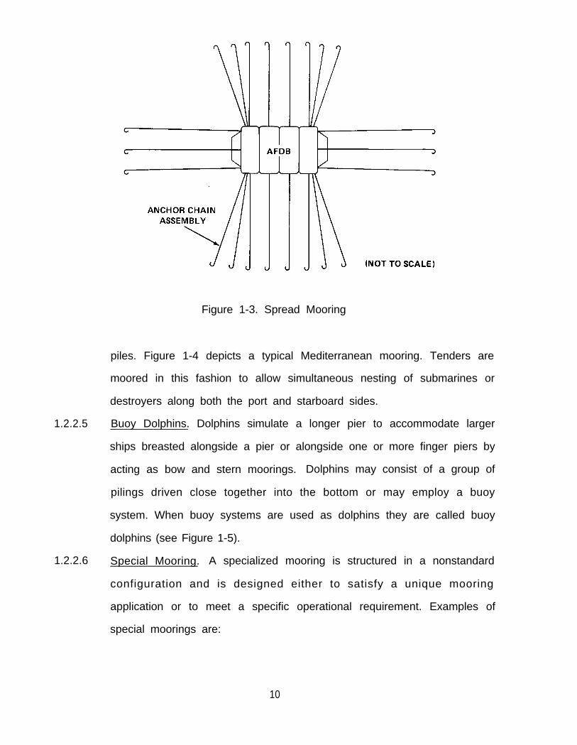
Figure 1-3. Spread Mooring
piles. Figure 1-4 depicts a typical Mediterranean mooring. Tenders are
moored in this fashion to allow simultaneous nesting of submarines or
destroyers along both the port and starboard sides.
1.2.2.5 Buoy Dolphins. Dolphins simulate a longer pier to accommodate larger
ships breasted alongside a pier or alongside one or more finger piers by
acting as bow and stern moorings. Dolphins may consist of a group of
pilings driven close together into the bottom or may employ a buoy
system. When buoy systems are used as dolphins they are called buoy
dolphins (see Figure 1-5).
1.2.2.6 Special Mooring. A specialized mooring is structured in a nonstandard
configuration and is designed either to satisfy a unique mooring
application or to meet a specific operational requirement. Examples of
special moorings are:
10

Figure 1-5. Buoy Dolphin Mooring
11
●
●
●
●
●
●
Those temporarily installed in an Amphibious Objective Area (AOA)
for utilization by amphibious support ships.
Typhoon, hurricane, storm moorings.
Those installed in exposed areas that are subject to considerable
current, tide, wind, and wave actions.
Those installed in geographical areas where abnormal bottom
conditions require propellant embedment anchors (PEAs).
Those designed to provide restricted watch circles.
Those designed for use by submarines and containing a riser
fendering system which precludes damage to the submarine’s sonar
dome when moored to the buoy.
1.2.3 UPGRADED MOORINGS. All existing fleet moorings will be replaced with
upgraded mooring material. It is intended that these moorings will remain installed
for extended periods of time without overhaul vice the current 3- to 5-year time
period between overhauls. The upgraded moorings will include urethane coated
foam buoys, improved FM 3 chain and associated components, cathodic protection,
and a more efficient anchor assembly.
1.2.4 MOORING CLASSIFICATIONS. NAVFAC DM 26.6, “Mooring Design Physical
and Empirical Data, ” identifies the different classes of fleet moorings. A fleet
mooring is classified according to its holding capacity. Table 1-1 lists the classes of
Navy fleet moorings and the required size of the riser and anchor chain
subassemblies. These standard classes have been designed to support the various
types and sizes of operational fleet vessels. The larger classes (AA through CC) are
configured with paired anchor legs attached to spider plates, and can have six to
eight anchor chain subassemblies (see Figure 1-6).
12

Table 1-1. Classes of Navy Fleet Moorings
Class
AA
BB
c c
DD
A
B
c
D
E
HoldingCapacity (Ibs)
300,000
250,000
200,000
175,000
150,000
125,000
100,000
75,000
50,000
Type of AnchorChain Subassemblies
Twin
Twin
Single
Single
Single
Single
Single
Single
Single
Chain Size (in)Riser Anchor
4
3-1/2
3-1/2
3
2-3/4
2-1/2
2-1/4
2
1 -3/4
2-3/4
2-1/2
2-1/4
3
2-314
2-1/2
2-1/4
2
1 -3/4
Figure 1-6. Typical Large Riser-Type Mooring
13

1.2.5 MAJOR FLEET MOORING ASSEMBLIES. A typical fleet mooring is made up of
one or more buoy systems. Each buoy system in turn consists of a specific
combination of the four basic assemblies listed below.
1.2.5.1
1.2.5.2
1.2.5.3
1.2.5.4
●
●
●
●
Buoy assembly, which includes the following:
Hull subassembly.
Fender subassembly.
Chafing strip subassembly.
Chain assembly, which includes the following:
Riser subassembly.
Anchor chain subassembly.
Anchor assembly.
Cathodic protection assembly.
Moorings which do not require a buoy will, of course, consist only of the chain,
anchor, and cathodic protection assemblies.
1.2.6 TYPES OF BUOY SYSTEMS. Although there are many specific buoy system
designs, there are only two basic types of buoy systems: riser and non-riser. Each of
these types is defined by the configuration of the anchor, chain, and buoy
assemblies which make up the buoy system.
1.2.6.1 Riser Buoy System. This system consists of a hawsepipe or tension bar
type buoy, a riser chain subassembly (which includes a ground ring),
anchor chain subassemblies, and anchors. The single riser connects the
buoy to the ground ring located about 10 feet above the bottom. Two,
three, or four anchor chains run from the ground ring to the anchors (see
Figure l-l).
1 4

1.2.6.2 Non-Riser BUOY System. Previously called a telephone-type buoy system,
the non-riser system consists of a relatively large buoy held in place by
three to eight anchor chain subassemblies and anchors. Each of the
anchor chains is attached to a padeye on the lower side of the buoy hull.
A ship using this buoy connects its chain or bow lines to a swivel in the
center of the buoy’s deck. The non-riser system has a relatively small
watch circle compared to the riser-type buoy system (see Figure l-l).
1.2.7 MOORING COMPONENTS. Appendix B contains descriptions and drawings of
the components normally used in fleet moorings. The components are grouped
into categories related to the four basic assemblies which make up a fleet mooring:
buoys, chain and accessories, anchors, and cathodic protection. The terminology
used in Appendix B is preferred for use in all fleet mooring documentation,
correspondence, reports, drawings, etc. Other common names are included which
reflect usage by the offshore industry. However, the standard terminology
appearing in Appendix B should be used so that a common understanding of terms
will exist among those responsible for designing, maintaining, and managing fleet
moorings. This becomes especial ly important wi th respect to as-bui l t
documentation, inventory reports, and requests for material.
15
2.0 MOORING INSTALLATION AND RECOVERY
2.1 PREPARATION
2.1.1 GENERAL. This chapter describes methods for installing and recovering
moorings in shel tered waters and provides the general procedures for
accomplishing these tasks. Installation and recovery of both riser and non-riser
buoy systems are covered. Procedures set forth may be modified to suit local
environmental conditions and/or material constraints, or to accommodate a special
mooring design. The procedures developed herein assume that the tasks will be
accomplished using a floating crane or crane barge for installation and recovery.
2.1.2 PLANNING AND PREPARATION. Development of a plan is a necessary
requirement prior to commencing operations. The plan should include the
equipment needed and the procedures necessary for accomplishment of the task.
Design drawings, as well as materials required, should also be included. Recovery
plans should take into account the as-built drawings. The plan should be prepared
well enough in advance to allow riggers, crane and barge operators, design
engineers, and others to review and comment on the details. Pr ior to
commencement of offshore operations, all persons involved should understand the
general sequence of events that will occur and their specific responsibilities in the
effort. The plan should also take into consideration the following:
2.1.2.1 Preparation. Thorough preparation is one of the principal keys to a
successful mooring installation or recovery operation. Proper ashore
preparations will ensure that offshore operations will be expeditiously
and efficiently carried out. As examples:
● A floating crane will be provided for the installation or recovery of
mooring components. The size and placement of required
temporary padeyes must be determined and action taken to install
these padeyes on the deck of the barge.
16

● Physical fit checks of all mooring materials should be accomplished
to ensure proper assembly of the mooring in accordance with
design specifications.
● If being installed, chain stud anodes should be attached to the chain
prior to moving the material offshore. After anode installation,
caution must be taken in handling the chain to preclude damage to
or Ioss of the anodes.
2.1,2.2 Environmental Factors. Since offshore operations can be strongly
influenced by environmental conditions, plans should be made flexible
enough to allow for unexpected delays due to inclement weather or
rough seas.
2.1.3 TOOLS AND EQUIPMENT REQUIRED. The floating crane or other suitable
platform will be stocked with all tools needed not only for the planned operation,
but also for any field modifications or in place repairs that may be required. Tools,
equipment, and materials for the effort should include the following items:
● Welding and cutting equipment.
● High-pressure seawater pump (100 psi) or a water blaster.
● Spare parts (e.g., locking pins, punches, retaining pellets, etc.). A good
source is BUSHIPS No. 52603-840327.
● Lubricants, preservative greases, coatings, etc.
2.1.4 PRE-INSTALLATION LAYOUT. Mooring components will be laid out on the
crane barge, prior to offshore operations, in an arrangement governed by
procedures established for installation of the mooring. Chains shall be placed so
that they will readily pay out during a controlled installation. Figure 2-1 illustrates a
typical mooring material/component layout on a crane barge. The mooring should
be assembled on the barge to the maximum extent possible prior to departing for
installation operations to minimize assembly activity offshore.
17

2.1.5 PRE-INSTALLATION POSITIONING. A mooring is designed for installation at a
specific site. The characteristics of the site (e.g., water depth, bottom conditions)
will determine the mooring design features such as length of riser and anchor chain
subassemblies and fluke angle of the anchor. It is important, therefore, that the
mooring be placed in the location for which it was designed, since a misplaced
mooring would require the expense and effort of reinstalling the entire system.
Equipment used for positioning the mooring is described below.
Figure 2-1. Typical Layout of Mooring Equipment Aboard a Crane Barge
2.1.5.1 Marker Buoys. To ensure that the mooring is installed in the right
location and that the anchor chain assemblies are properly orientated,
marker buoys should be placed at the desired points at the site before
installation begins. A center marker buoy will be used to indicate the
position of the buoy; ring markers will be used to indicate anchor
locations; and range markers will be used to assist in anchor chain
subassembly orientation (see Figure 2-2). Correct placement of anchors
will ensure that the anchor legs are straight and taut. Range buoys may
18
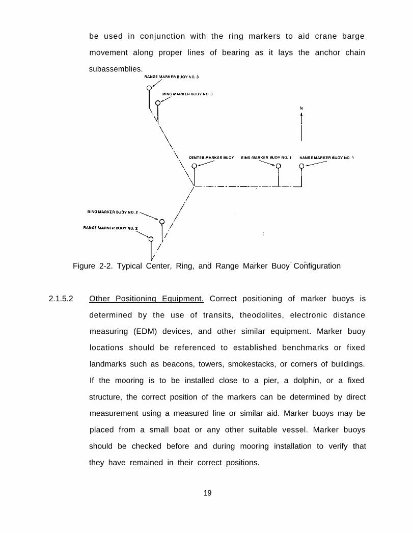
be used in conjunction with the ring markers to aid crane barge
movement along proper lines of bearing as it lays the anchor chain
subassemblies.
Figure 2-2. Typical Center, Ring, and Range Marker Buoy Configuration
2.1.5.2 Other Positioning Equipment. Correct positioning of marker buoys is
determined by the use of transits, theodolites, electronic distance
measuring (EDM) devices, and other similar equipment. Marker buoy
locations should be referenced to established benchmarks or fixed
landmarks such as beacons, towers, smokestacks, or corners of buildings.
If the mooring is to be installed close to a pier, a dolphin, or a fixed
structure, the correct position of the markers can be determined by direct
measurement using a measured line or similar aid. Marker buoys may be
placed from a small boat or any other suitable vessel. Marker buoys
should be checked before and during mooring installation to verify that
they have remained in their correct positions.
19

2.1.6 PRE-INSTALLATION INSPECTION. A final inspection shall be made of all
mooring material before any item leaves the storage area or prior to the material
being laid out on the crane barge deck. This will include a check of all chain
connections, joining links, and other fittings for proper and secure assembly.
2.1.7 FIELD CHANGES OF DESIGN. Moorings are usually designed for a specific
application at a specific site. The chain size, anchor weight, anchor fluke angle,
length of anchor chain subassemblies, length of riser chain, buoy size, and other
factors have been determined based on the holding power requirements and
planned location of the mooring. Field changes to design specifications and
planned installation procedures should not be made without approval of the
cognizant design engineer because incorrect actions could adversely affect the
performance and reliability of the mooring.
The choice of the type, size, and configuration of anchors is a design
consideration for a particular mooring or a particular mooring location. Recent
work in mooring design by the Naval Civil Engineering Laboratory, Port Hueneme,
California, has resulted in a much better understanding of anchor holding capacity.
This information is incorporated in DM-26.6 and is not presented here. The
important consideration is that anchor selection is a complex design problem and
that small changes to items such as fluke angle, stabilizer length, and orientation
when placed on the bottom, can drastically affect the holding capacity of the
mooring.
2.1.8 AS-BUILT DRAWINGS. Accurate as-built records (such as shown in Figure 2-3)
must be maintained on all installed moorings. As-built drawings should be
prepared immediately following the installation, and copies shall be submitted to
NAVFACENGCOM (Code 1002).
20

2.2 INSTALLATION INSTRUCTIONS
2.2.1 GENERAL. General installation procedures for the typical three-legged riser
mooring system are presented below. The procedures are preceded by a description
of the main parts of the mooring system which should be assembled before offshore
operations begin.
2.2.2 RISER-TYPE MOORING SYSTEM. Installation of this mooring system shall
generally follow the procedure set forth below.
2.2.2.1 Preinstallation Assembly. A three-legged riser-type mooring system is
normally assembled in three parts:
● Part I. This part is the first anchor chain subassembly with a sinker
and anchor.
● Part Il. This part includes the buoy, the riser chain subassembly from
the buoy to the ground ring, and the second anchor chain
subassembly with a sinker and anchor (see Figure 2-4).
● Part III. This part is the third anchor chain subassembly with a sinker
and anchor.
2.2.2.2 Installation Procedures. The marker buoys will be placed in their desired
locations. The center marker buoy will be placed in the desired position
of the mooring buoy. The ring marker buoys will be installed 25 feet past
the point that the anchors will be lowered to the bottom and released.
Predicted drag distance of the anchor is needed to determine this point.
Appendix E provides tables of predicted drag distances. The desired final
location of the anchors should be indicated on the design drawing.
provided by the mooring designer. After pulling the anchor to set it and
test its capacity, (see 2.2.2.3) the final position of the anchor must be
within a 40 foot by 20 foot box with the desired location at the center of
the box (see Appendix E, Figure E-2). The range marker buoys should be
22

installed about 50 feet beyond the ring marker buoys on the extens
of the Iines from the center marker buoy to the ring marker buoys.
Figure 2-4. Typical Riser-Type Mooring Material Pre-lnstallation Layout
NOTE
Refer to Paragraph 2.2.2.1 for references to
"Part l," " Part II," and "Part III" in the procedures
that follow.
Before beginning installation of the system, the free end of the first
anchor chain subassembly of Part I should be attached to a pickup buoy
for easy recovery during the placement operation.
23

These general installation procedures should then be followed:
● Position the crane barge near one of the ring marker buoys (the one
within 25 feet of the desired position for the anchor of the first
anchor chain subassembly of Part l). During some installations, it
may be necessary to weld the anchor flukes (see Figure 2-5) to a
predetermined angle.
NOTE
Wind and current conditions will usually
dictate which subassembly is laid first.
Figure 2-5. Welding Anchor Flukestoa Required Angle
24

● The first anchor is slung by a bridle in a horizontal position and has
attached to i t a crown marker buoy and one anchor leg
subassembly. The anchor is fitted with a pelican hook or a toggle
bar quick release system as shown in Figure 2-6. The crane lowers
the anchor and chain simultaneously over the side. When installing
moorings equipped with chain stud anodes (see Section 8.3.1.1),
care must be exercised that the chain does not drag over sharp
edges which can result in some of the anodes being stripped off.
● Upon reaching the bottom, release the anchor and recover the
bridle. Move the barge toward the center marker buoy while
slowly lowering the chain with a flat catenary.
● Upon approaching the center marker buoy, pull the subassembly
taut so that the anchor is properly set. Then, lower the bitter end of
the chain (with a pickup buoy attached to it) to the bottom.
● The crane barge now proceeds to the second marker buoy and
lowers the anchor (of Part II) 25 feet from the marker toward the
center marker buoy. The anchor is fitted with a quick release
mechanism and has a crown buoy attached to it.
● Upon reaching the bottom, release the anchor and recover the
bridle. Move the barge toward the center marker buoy while
slowly lowering the chain with a flat catenary. Upon approaching
the center marker buoy, pull the subassembly taut so that the
anchor is properly set. Then, using the pickup buoy, retrieve the
end of the first anchor chain subassembly and attach it to the
ground ring. Attach the bitter end of the third anchor chain
subassembly (Part Ill) to the ground ring also. Then lower the
25

Figure 2-6. Lifting Bridle and Release Mechanism
26
ground ring, riser, and buoy into the water alongside the center
marker buoy.
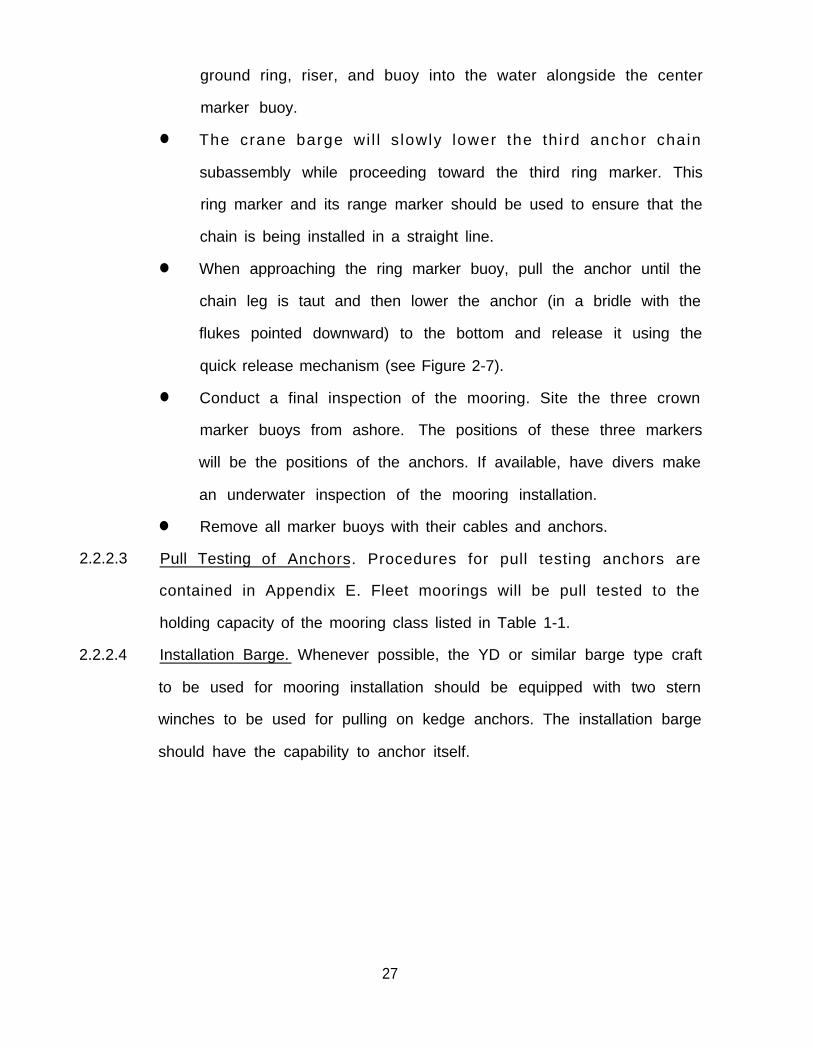
● The crane barge wi l l s lowly lower the th i rd anchor chain
subassembly while proceeding toward the third ring marker. This
ring marker and its range marker should be used to ensure that the
chain is being installed in a straight line.
● When approaching the ring marker buoy, pull the anchor until the
chain leg is taut and then lower the anchor (in a bridle with the
flukes pointed downward) to the bottom and release it using the
quick release mechanism (see Figure 2-7).
● Conduct a final inspection of the mooring. Site the three crown
marker buoys from ashore. The positions of these three markers
will be the positions of the anchors. If available, have divers make
an underwater inspection of the mooring installation.
● Remove all marker buoys with their cables and anchors.
2.2.2.3 Pull Testing of Anchors. Procedures for pull testing anchors are
contained in Appendix E. Fleet moorings will be pull tested to the
holding capacity of the mooring class listed in Table 1-1.
2.2.2.4 Installation Barge. Whenever possible, the YD or similar barge type craft
to be used for mooring installation should be equipped with two stern
winches to be used for pulling on kedge anchors. The installation barge
should have the capability to anchor itself.
27

Figure 2-7. Typical Riser-Type Mooring Installation
NOTEDivers may be used to inspect connections and tocheck the orientation and tautness of the anchorchains. They may also be used to jet the anchors intothe bottom if included as part of the designspecification.
28

2.3 RECOVERY INSTRUCTIONS
2.3.1 RISER-TYPE MOORING SYSTEM. These systems are recovered by removing one
anchor chain subassembly at a time. Proceed as follows:
● Sling the buoy from the top jewelry.
● Lift the buoy and riser until the ground ring is level with the deck of the
crane barge (see Figure 2-8).
NOTE
In the case of a taut mooring, one anchor chain
subassembly may have to be separated from the
ground ring by cutting the first A-link below the
ground ring with a torch.
● Stopper off the ground ring (see Figure 2-9).
● Lower the buoy down to the deck on its side. Disconnect the riser, and
either block the buoy on its side or place it on blocks to avoid damaging
the tension bar.
● Disconnect the riser from the ground ring and buoy.
NOTE
If the joining link cannot be removed, cut the first
A-link with a torch.
● Sling the ground ring and lift it until the anchor
accessible.
● Stopper off one subassembly (see Figure 2-10).
chain subassemblies are
29
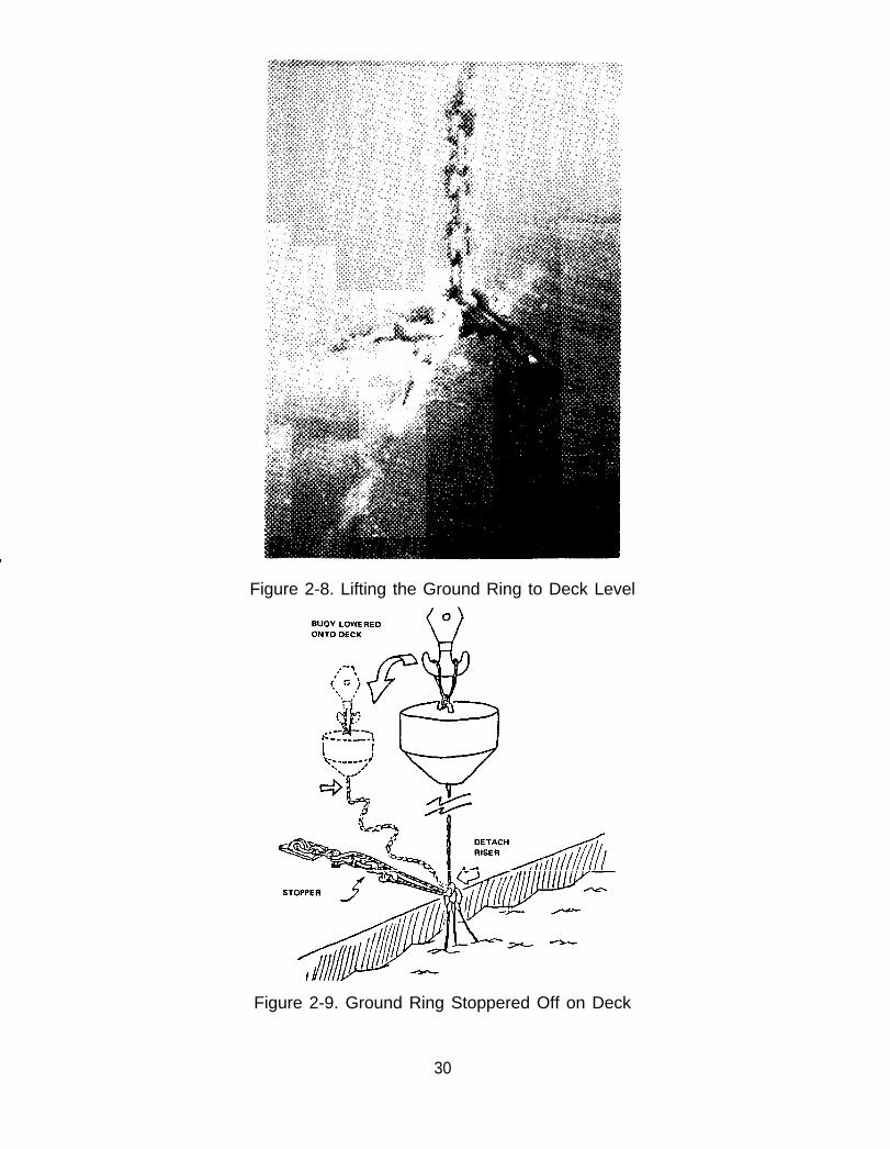
Figure 2-8. Lifting the Ground Ring to Deck Level
Figure 2-9. Ground Ring Stoppered Off on Deck
30

Figure 2-10. One Leg Stoppered Off
●
●
●
●
●
Attach a retrieval buoy to each of the other two subassemblies. The third
subassembly and the ground ring will be considered together. Fake the
retriever buoy lines on deck to allow easy running.
Cut one subassembly free from the ground ring one link below the chain
joining link. Allow the chain to drop and retriever buoy to run free and
over the side.
Repeat with the other leg that has a retriever buoy attached. Lower the
ground ring on deck (see Figure 2-1 1). Disassemble the chain joining
link, if possible, and disconnect the ground ring from the subassembly.
Sling the chain to the main hoist, raise and remove the stopper.
Continue raising until the next chain joining link is above deck.
3 1

Figure 2-11. Two Anchor Chain Subassemblies Overboarded
Stopper the chain, 3 links below the chain joining link, and lower the
chain joining Iink to the deck for disassembly,
●
●
When severed, move this shot of chain aside.
Sling the chain and continue lifting and detaching chain shots as before.
NOTEAll components recovered should be washed down
with seawater before being brought aboard the
barge. Use a high-pressure hose for this purpose (see
Figure 2-12).
● When all of the chain has been recovered, bring the anchor aboard.
● Pick up a retriever buoy and, using the same procedures, recover a
second subassembly and anchor. Then recover the third.
32

Figure 2-12. Using High Pressure Hose for Cleaning
33

3.0 INSPECTIONS
3.1 GENERAL
3.1.1 OVERALL REQUIREMENTS. All mooring components, either in use or in
storage, must be periodically inspected to determine their current material
condition and their future maintenance requirements. The importance of these
inspections cannot be overemphasized because the effectiveness of any
maintenance program will always depend on how often and how well these checks
and services are performed. Inspection plans, therefore, should take into
consideration the crit ical elements of frequency of inspections and the
thoroughness, completeness, and quality of work.
3.1.2 INSPECTION CLASSIFICATIONS AND TYPES. For the purposes of this manual,
inspections are classified as either in-service or out-of-service. In-service inspections
are performed on installed moorings; out-of-service inspections are performed on
components stored ashore. There are four basic types of in-service inspections, as
follows:
● Annual surface inspections.
● Underwater inspections.
● Lift inspections.
● Damage/failure inspections.
The above in-service types are addressed and discussed in this chapter. Out-of-
service inspections are covered in chapters 5.0,6.0,7.0, and 8.0.
3.1.3 PURPOSE. The primary purpose of in-service inspections is to determine the
general physical condition of the buoy(s) and chain assemblies. The results of these
inspections are used to decide if a mooring is safe for continued use. Routine
inspections also provide an opportunity to detect and remedy minor material
deficiencies. Future maintenance requirements are strongly dependent on the
results of periodic in-service inspections.
34

3.1.4 PERSONNEL. Because in-service inspections are conducted offshore, and often
under less than ideal conditions, experienced personnel, as well as reliable
equipment, are required to accomplish these tasks. Topside personnel or divers will
be used to clean and inspect a representative portion of the buoy hull and chain
assemblies. The inspection report of their findings will then be used to assess the
condition of the entire mooring. Measurements taken, observations made, and
data accumulated must, therefore, be highly accurate and complete in these
instances.
3.2 INSPECTION PROCEDURES
3.2.1 GENERAL. The following paragraphs contain descriptions of the four basic
types of in-service inspections and provide guidelines for performing these
inspections.
3.2.2 ANNUAL SURFACE INSPECTIONS. Shore activities that operate and maintain
fleet moorings must inspect the visible portion of each mooring buoy at least once
each year. The purpose of this annual surface inspection is to ensure that the buoy
and its topside hardware, fenders, and chafing strips are in satisfactory condition,
and to verify that the mooring has not been dragged from its proper location.
3.2.2.1 Buoy Inspection. The buoy should be closely examined to determine its
overall condition. The following should be documented:
● Caliper measurements of the upper jewelry whenever these appear
to be excessively worn out or in marginal condition (see Figure 3-l).
● in addition, any excess top jewelry or wire rope cables attached to
the buoy should be reported.
● Physical damage such as holes, dents, metal distortion, or listing
(see Figure 3-2).
● Measurement of the buoy’s freeboard.
35

Figure 3-1. An Example of Severely Worn Top Jewelry
Figure 3-2. Severe Buoy List
36

● Condition of fiberglass on fiberglass-coated buoys. (Fiberglass
should be inspected and any cracks, wear, peeling, or rust bleeding
identified.)
● Condition of paint on painted buoys. (Paint should be checked for
cracking, chipping, and/or peeling.)
● Condition of water drains and buoy surface penetrations. (Examine
for broken parts, surface rust, and surface pitting.) (See Figure 3-3.)
Figure 3-3. Pitting/Rusting on the Side of a Buoy
● Condition of fenders and chafing strips. (Check for physical
integr i ty and secure connect ions to the buoy’s surface.
Fender/chafing strip brackets or studs will be inspected for
corrosion and/or cracks.)
3.2.2.2 BUOY Location. If it is suspected that a mooring has been dragged from
its desired geographic location, the current position of its buoy will be
37

verified by sighting from known positions ashore using a transit, a
theodolite, or any instrument of comparable precision.
3.2.2.3 Documentation. The results of the surface inspection shall be fully
documented (see Figure 3-4, “Sample Surface Inspection Form”) and filed
in the inspecting activity’s maintenance files for future reference. A copy
of this form should be forwarded to CHESNAVFACENGCOM Code FPO-1
for entry into the FMM archives. if a buoy is found to be in relatively
poor condition or in need of repair or overhaul, complete information
concerning funding and the material required to correct the observed
deficiencies should be reported to CHESNAVFACENGCOM.
3.2.3 UNDERWATER INSPECTIONS. The purpose of mooring underwater
inspections is to determine the general condition of buoys and chain assemblies and
to verify or update existing as-built drawings and maintenance records. Each fleet
mooring will be inspected by divers every 2 to 3 years. CHESNAVFACENGCOM has
the overall responsibility for all of these underwater mooring inspections and will
make arrangements for each inspection, analyze the raw data observed, and
prepare reports of the inspection findings. Divers assigned for each inspection will
inspect only a portion of the submerged buoy hull and chain assemblies in order to
compi le a general descr ipt ion of the moor ing’s condi t ion. Consistent
measurements obtained during each inspection will provide a good indication of
the mooring’s overall condition. Obviously, underwater inspections cannot fully
substitute for a complete inspection involving recovery of the mooring and the
measurement and evaluation of each component.
3.2.4 LIFT INSPECTIONS. In the past, a buoy and riser chain were lifted as high as
possible out of the water and a visual inspection of the buoy, its upper and lower
jewelry, and accessible portions of the riser chain subassembly was conducted to
determine wear, corrosion, or deterioration. Lift inspections have been
38
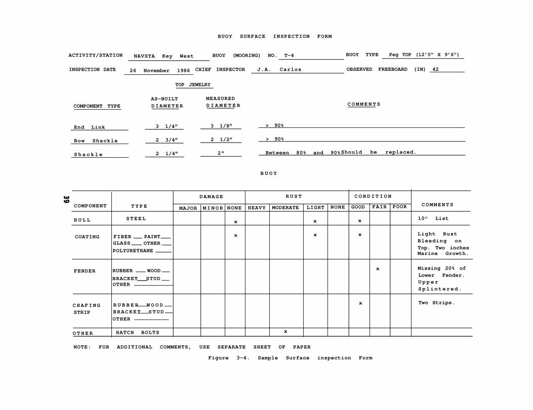
BUOY SURFACE INSPECTION FORM
ACTIVITY/STATION NAVSTA Key West BUOY (MOORING) NO. T-4 BUOY TYPE Peg TOP (12’0" X 9’6")
INSPECTION DATE 26 November 1986 CHIEF INSPECTOR J.A. Carlos OBSERVED FREEBOARD (IN) 42
TOP JEWELRY
AS-BUILT MEASURED
COMPONENT TYPE DIAMETER D I A M E T E R C O M M E N T S
End Link 3 1/4” 3 1/8” > 90%
Bow Shackle 2 3/4” 2 1/2” > 90%
S h a c k l e 2 1/4” 2“ Between 80% and 90%.Should be replaced.
B U O Y
DAMAGE R U S T C O N D I T I O N
COMPONENT T Y P E MAJOR M I N O R NONE HEAVY MODERATE LIGHT NONE GOOD FAIR POOR
H U L L STEELx x x
COATING FIBER PAINT x x x
GLASS OTHER
POLYURETHANE
FENDER RUBBER WOOD x
BRACKET STUDOTHER
CHAFING R U B B E R W O O D x
STRIP BRACKET STUD
OTHER
HATCH BOLTS xO T H E R
NOTE: FOR ADDITIONAL COMMENTS, USE SEPARATE SHEET OF PAPER
COMMENTS
10° List
Light RustBleeding onTop. Two inchesMarine Growth.
Missing 20% ofLower Fender.U p p e rSplintered.
Two Strips.
Figure 3-4. Sample Surface inspection Form

discontinued in favor of underwater diver inspections and will no longer be
conducted. To avoid disturbing the anchors, a mooring should be lifted only when
the buoy and/or riser chain require repair or replacement, or when the mooring is
being completely removed.
3.2.5 MOORING DAMAGE/FAILURE INSPECTIONS. Fleet moorings can be damaged
by collisions or dragged out of position by heavy winds or seas. They can also fail
because of broken mooring components. An inspection of mooring damage, drag,
or failure should be conducted as soon as possible after detection. If a collision has
occurred, then the purpose of the inspection is to determine the extent of the
damage and whether the buoy is in danger of sinking. If the buoy is found to have
hull damage and is in danger of sinking, a marker buoy should immediately be
attached to it so that the buoy’s position will be marked in the event that it sinks.
Arrangements should then be made to recover the buoy at the earliest opportunity
so that repairs can be accomplished. If the buoy is undamaged, but the mooring has
been pulled off location, arrangements should be made to recover the mooring and
reinstall it in its proper position.
3.2.5.1 Inspection Procedures. Inspection will include the following:
● Visual inspection of the buoy’s hull and associated fenders for
damage (dents, broken fenders, scrapes, hull punctures, etc.).
● Check for buoy drag and the excursion of the entire mooring (new
positions should be sighted from known benchmarks ashore and
recorded).
● Check for riser chain failures which will cause buoys to float free
from their intended position. Free floating buoys should either be
towed to shore or temporarily attached to an anchor.
3.2.5.2 Documentation. The results of the damage inspection shall be fully
documented. In all cases of damage or suspected damage to a fleet
40
mooring, the cognizant port authority should be notified so that the
mooring will not be used. At most Navy installations, this authority rests
with the Port Services Officer. A failure report must also be submitted as
detailed in Paragraph 1.1.7.1 of this document.
41
4.0 IN-SERVICE MAINTENANCE AND REPAIR
4.1 GENERAL
4.1.1 SCOPE. In-service maintenance and repair will be limited to the following:
● Minor underwater repairs.
● Minor buoy and riser assembly repairs.
● Replacement of damaged buoys and/or riser assemblies.
● Minor repairs to cathodic protection systems.
It should be noted that sufficient lift capability will be needed for replacement of
buoys and/or riser assemblies and, in many instances, for repairs. All of the
maintenance functions listed above are covered in this chapter except for cathodic
protection, which is discussed in Section 8.0.
4.1.2 EQUIPMENT. The following equipment must be readily available for use as
needed:
● Crane barge or floating crane.
● Tugboat, mule, or other vessel (for maneuvering and positioning the
crane platform).
● High-pressure water pump and hose (for cleaning).
4.2 PROCEDURES
4.2.1 BUOY REPLACEMENT (RISER-TYPE). A buoy in a riser-type system can be
replaced without removing the mooring. Proceed with the replacement as follows:
● Lift the buoy out of the water and wash it down with seawater from a
high pressure hose.
● Secure the riser chain to a bitt or cleat with a wire rope sling.
● Detach the buoy from the chain by removing the anchor joining link or
buoy shackle located directly under the buoy.
42

NOTE
If a replacement joning link is not available, the removed
joining link can be cleaned, recoated with a preservative
grease, and reused to secure the new buoy to the riser
chain.
● Secure new buoy to riser chain.
● Lower new buoy into position in the water.
NOTE
When a tension bar type buoy is lifted onto a barge deck, it
should be placed on railroad ties or on chocks to prevent
damage to the lower portion of the tension bar.
4.2.2 RISER REPLACEMENT.
● Lift the buoy and
Riser replacement will be accomplished as follows:
its attached riser chain out of the water and wash down
with a high-pressure hose.
● Hoist buoy and riser chain aboard the barge.
● Hold the ground ring on a deck stopper.
● Disconnect riser from the ground ring and buoy.
● Attach new riser to the buoy and ground ring.
● Reinstall buoy and riser in the water.
The above steps are standard procedure for moorings installed in shallow water. In
deep water, however, the ground ring, in all probability, will not be able to be lifted
43

on the deck of the barge without disturbing the anchors. In this situation the
mooring will have to be recovered in order to replace the riser, and then reinstalled
(refer to Section 2.0).
4.2.3 BUOY REPLACEMENT (NON-RISER-TYPE). A non-riser-type buoy will be more
difficult to retrieve than a riser-type. If the mooring has been properly installed,
there will be a catenary section of chain suspended in the water between the buoy
and the anchor. If the catenary angle is large (as in a taut, properly installed
mooring), then it may not be possible to stopper off all four anchor chain
subassemblies on the barge deck simultaneously. It should also be noted that, in
this type of installation, the buoy is kept in place by balanced opposing forces
created by the catenaries of the anchor chain subassemblies. When one of the
subassemblies is cut, the buoy will be pulled in the direction of the opposing” leg.
This pull will result in a potentially dangerous horizontal force on the crane boom,
especially if the buoy is being held aloft when the chain is cut. Connecting the
replacement buoy to the anchor chain subassemblies is also difficult under these
conditions. Therefore, in the case of a taut mooring, it is recommended that the
non-riser buoy system be completely recovered prior to replacing the buoy, and that
the mooring be reinstalled in accordance with the procedures set forth in Section
2.0. In many non-riser installations, significant slack exists in the anchor chain
subassemblies directly below the buoy. In such cases it may be possible to lift the
buoy and simultaneously stopper off the legs on the barge deck. The new buoy can
then be connected to the anchor chains and replaced in the water.
4.2.4 MINOR REPAIRS. In-service minor repairs to a buoy, such as replacing a
fender, repairing
replacing anodes,
the buoy ashore.
chain accessories
an upper hull puncture, patching fiberglass or polyurethane,
or spot painting the buoy, can be accomplished without taking
Detailed procedures for the refurbishment of buoys, chain, and
are contained in Chapters 5 and 6. Although emergency
44
replacement of smaller sizes of mooring chain components can be accomplished
underwater by divers, mooring component replacement, welding, and other minor
repairs should be accomplished aboard a crane barge. If it is necessary to enter a
buoy, this should be done only when the buoy is ashore or aboard a barge where
there is no possibility of the buoy’s sinking. Special care must be taken to reseal the
manhole and assure watertight integrity (See Paragraph 5.3.2.5 for leak test
procedures).
WARNING
Buoy manhole covers should not be removed while
the buoy is in the water.
During the inspection of a mooring buoy, its associated top and bottom hardware
should be closely inspected to determine whether any components need to be
reconditioned or replaced. When reconditioning/replacement is required, the
following should be observed:
4.2.4.1 Welding/Cutting. Welding chain appendages or cutting out retaining
pins or rivets with a torch should never be done because heating will
introduce internal stresses and reduce the strength of heat-treated steel
components.
4.2.4.2 Shackles/Joining Links. Ensure that shackles, joining links, and other such
fittings with removable parts are treated with an appropriate grease
preservative and refitted. Care should be taken not to interchange
matched parts of joining links. This can be avoided by tagging each part
of the joining link with a unique identification number or by matching
the stamped numbers on the parts (see Figure 4-l). Locking pins of
45

joining links and shackles should never be welded in place due to the
probable resultant loss of tensile strength of the component.
Figure 4-1. Mooring Material Markings
4.2.5 BUOY COATINGS. Because protective coatings are frequently damaged by
impact or abrasion, it may be necessary to make in-service repairs to coatings of
mooring buoys. In order to repair these coatings, it is necessary to first clean the
exposed steel and the area surrounding the steel of rust, salt, and loose material.
This can be accomplished by wire brushing the steel (preferably power wire
brushing) or by scrubbing with a bristle brush and then drying the area with an
airhose connected to an oil free compressor (when required). The intact coating
surrounding the damaged areas should be abraded to ensure proper bond of the
repair material. There are several proprietary putty-like coatings available called
splash-zone compounds, that can be spread over the cleaned area, wet or dry. MI L-
P-28579(YD) describes such a curing epoxy-polyamide formulation. There are also
available a number of proprietary brush on coatings that can be applied to damp
surfaces and will cure either above or under water. Either type of coating should
completely cover the steel and extend at least one-half inch over the cleaned
coating surrounding the steel.
46

5.0 ASHORE INSPECTION AND REFURBISHMENT OF BUOYS
5.1 GENERAL
5.1.1 SCOPE. Ashore inspection and refurbishment of buoys will include visual
inspections, repairs, tests, and replacement of damaged components. There are
two types of buoy inspections: preliminary and detailed. The purpose of a
preliminary inspection is to determine whether the buoy is in a condition for a
further, more detailed inspection and subsequent refurbishment or whether it
should be disposed of at this stage. lf the results of the preliminary inspection
indicate that refurbishment will be cost-effective, then a detailed inspection will be
conducted. The buoy must be cleaned, completely inspected, and tested for airtight
integrity to determine all repair requirements. The buoy can also be sandblasted to
near white metal and, if required, a liquid dye penetrant or magnetic particle test
must be conducted.
5,1.2 PREPARATION FOR ASHORE INSPECTIONS. Prepare the buoy(s) for ashore
inspection as follows:
● Clean off buoy with high-pressure water during recovery.
● When brought ashore, place the buoy on chocks (railroad ties, cinder
blocks, etc.) to keep the tension bar clear of the ground. For ease of
working, the peg-top type buoy should be placed inverted on chocks.
● Remove the top and bottom jewelry, fenders, chafing strips, and
manhole covers. Mark manhole cover positions before removal for later
replacement in the same location.
● Remove shackle and joining Iinks from the buoy, as necessary.
47
NOTE
After removal, shackles and joining links should be reassembled
as complete units, including pins. Shackle pins and tapered
locking pins should be used only in their original parent
component.
5.2. INSPECTION PROCEDURES
5.2.1 PRELIMINARY INSPECTION. Before beginning the preliminary inspection, a 1-
foot-square section of the top and bottom and four l-foot-square sections (two
above and two below the water line) of the side hull plates should be cleaned to
bare metal. Visually inspect these four sections for pitting. In addition, perform a
visual inspection as follows:
●
●
●
●
●
●
●
Inspect the fenders and chafing strip fastenings for corrosion and wear.
Check hull and deck plates for corrosion, cracks, pitting, and watertight
integrity (see Figures 5-1 and 5-2).
Check the hawsepipe (if the buoy is so constructed) for rust, cracks,
pitting, or other material abnormalities.
Inspect the upper and lower ends of the tension bar (if the buoy is so
constructed) for wear, cracks, rust, or pitting.
If the buoy is a non-riser (telephone) type, check the padeyes for wear or
cracks.
Check the overall condition of the paint, fiberglass, or polyurethane
coating.
Check the interior of the buoy for rust or corrosion.
4 8
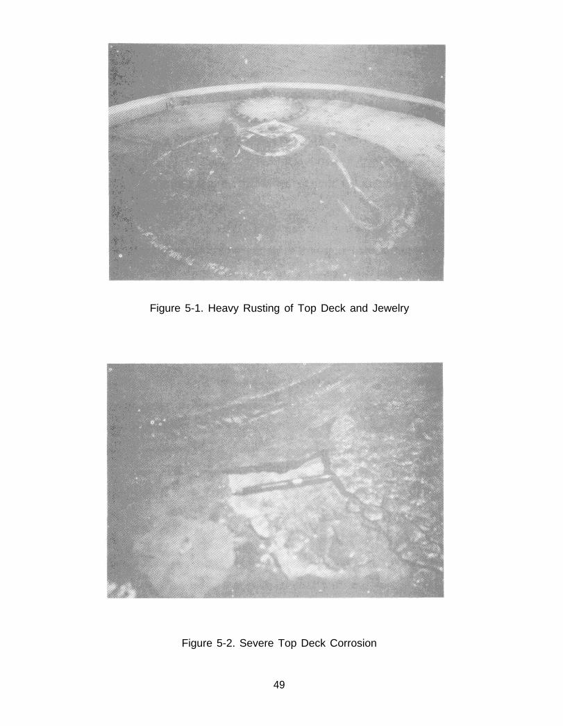
Figure 5-1. Heavy Rusting of Top Deck and Jewelry
Figure 5-2. Severe Top Deck Corrosion
49
Based on the results of this inspection (i.e., internal structural weaknesses, hull plate
cracks, severe pitting or rusting, broken tension bar, excessive corrosion, etc.), a
decision will be made whether to prepare the buoy for a detailed inspection or to
dispose of it.
5.2.2 DETAILED INSPECTION. Perform detailed inspection as follows:
5.2.2.1 Ultrasonic Testing. Conduct this test as follows:
● Sandblast the buoy to near white metal in accordance with SSPC-SP-
10.
● Inspect the buoy for damage, cracks, etc.
● Conduct an ultrasonic thickness test at four points on the buoy top,
four po in ts on the bo t tom, and e igh t po in ts a round the
circumference of the hull. Four of the foregoing eight points will
be below the waterline and four above the waterline.
● Using a pitting gauge, measure the depths of any pits observed on
the hull of the buoy. (Refer to Paragraph 5.2.2.2 following.)
5.2.2.2 Pitting Inspection. A visual inspection of the buoy hull plates will be
made for pitting. The extent of pitting will determine the remaining life
of the plates. ASTM G46-76, “Examination and Evaluation of Pitting
Corrosion, ” will be the standard reference used to evaluate the damage
and to formulate a quantitative expression that wil l indicate its
significance. To obtain a quantitative expression, ASTM G46-76
recommends that the deepest pit be measured, and that metal
penetration be expressed in terms of the maximum pit depth or the
average of the 10 deepest pits. Metal penetration can also be expressed
in terms of a pitting factor. This is a ratio of the deepest metal
penetration to the average metal penetration as shown in the following
relationship:
50
5.2.2.3
5.2.2.4
5.2.2.5
Pitting Factor = Deepest Metal Penetration
Average Metal Penetration
A pitting factor of “one” represents uniform corrosion. The larger the
number, the greater the depth of penetration. Pits will be rated in terms
of density, size, and depth.
Welds. Carefully check all welds, both internal and external, for cracks or
corrosion. If any cracks, fissures, or other flaws are found or are
suspected, then a liquid dye penetrant or magnetic particle test will be
performed to determine the extent of the defects.
Air Test. Air test each chamber/compartment in the buoy. Maintain 2 psi
design pressure in each compartment for 30 to 45 minutes (see
Paragraph 5.3.2.5 for procedures).
Documentation. The results of all inspections (both preliminary and
detailed) will be fully documented and filed for future reference. If a
buoy or its components are found to be in unsatisfactory condition, the
inspection results should be used in planning and estimating future
repair or replacement material requirements and associated labor costs.
R e p l a c e m e n t c o m p o n e n t s s h o u l d b e r e q u e s t e d f r o m
CHESNAVFACENGCOM.
5.3 BUOY REPAIRS AND MODIFICATIONS
5.3.1 GENERAL. Steel buoy repairs and modifications will include manhole cover
replacement, test plug and aperture maintenance, fender and chafing strip repairs,
welding requirements, and air pressure testing of the buoys.
5.3.2 PROCEDURES. Buoy repair and modification will be accomplished as
described below.
5.3.2.1 Manhole Cover Replacement. Manhole cover replacement will be
accomplished as follows:
51
NOTE
Each manhole cover will be replaced on the opening from
which it was originally removed. Match marks made on
cover and deck plate prior to removal will facilitate its
replacement in the correct location and position.
● Clean and lubricate the studs and use chaser nuts where required.
● Replace old gasket with a new l/8-inch silicone rubber gasket held
in place with RTV silicone gasket adhesive sealant (M IL-A-46106);
apply sealant only to bottom surface of gasket.
● Lift manhole cover by the extension lip and position it over studs.
CAUTION
Exercise care in lowering the cover on the studs so that stud
threads and gasket are not damaged.
● Lower manhole cover on studs.
● Secure cover bolts. Tighten in at least three steps using an opposite
bolt tightening sequence. Apply final 45-foot-pounds of torque.
5.3.2.2 Test Plugs and Hull Apertures. Clean and check test plug threads before
placement of the plugs in the hull apertures. Teflon sealant tape should
be applied to the threads to ensure a watertight seal.
5.3.2.3 Fenders and Chafing Strips. Overhauled steel buoys will be provided
rubber fenders and chafing strips. In most cases, this will require removal
of the wooden fenders and their channeling, and the wooden chafing
52

5.3.2.4
5.3.2.5
strips and connecting brackets. Channeling and brackets will be replaced
by stainless steel studbolts, 3/4-inch in diameter by 2 1/2 inches long (10
threads per inch). The bolts will be positioned and welded to conform to
predrilled holes in the rubber fenders and chafing strips. If the rubber
fenders and chafing strips are not predrilled, they will be drilled to
conform to the positions of the stud bolts. Spacing of the bolts shall not
exceed 16 inches on center. Figure 5-3 illustrates the recommended
attachment of fendering and chafing strips.
Welding. All welding will be accomplished by trained and qualified
personnel following accepted procedures and standards contained in the
latest edition of AWS D1.1, "The Structural Welding Code."
Buoy Air-Pressure Test.
tightness at the joints by
is under cover, at least 2
Each buoy compartment will be tested for
the application of air pressure. Unless the buoy
hours of clear weather will be required for the
test. The gauge used for the test must have a current
certification. Proceed as follows:
●
●
●
●
●
Install a test plug fitted with a gauge in the top of
calibration
each buoy
compartment.
Pressurize each
pressure for a
pressure.
compartment with 2 pounds per square-inch of
minimum of 30 minutes after stabil ization
air
o f
Brush all joints and seams with a solution of commercial leaktesting
fluid. Two percent potassium bichromate may be added to the
solution to inhibit the formation of rust.
Leaks detected will be repaired and the buoy retested.
When all tests and repairs are completed, completely remove leak
testing solution before applying surface primers.
53

Figure 5-3. Recommended Installation of Fenders on Fleet Mooring Buoys
54

5.4 PROTECTIVE COATINGS
5.4.1 PREPARATION FOR APPLICATION. -Preparation of buoys for application of
protective coatings will include the following:
● Remove fenders, chain links, steelplates, etc. from the mooring buoy.
● When possible, open buoy manhole and check the interior of the buoy
for rust and water damage.
● Examine hull for areas that may need repair or replacement.
● Pits found that are 3/16 of an inch deep or more will be filled with clad-
welding or epoxy repair compounds conforming with MI L-C-24176 and in
accordance with the applicable sections of the Naval Ships Technical
Manual, NAVSEA S9086-AA-STM-000.
● Buoys which are fiberglassed should have a steel reinforcing ring welded
around the outside edge of the manhole opening if one is not already
present. The purpose of the ring is to provide a clean, secure surface on
which to seat the manhole cover gasket as well as to reinforce the buoy
deck. The ring should be of l/2-inch steelplate and should extend a
minimum of two inches outward from the edge of the manhole opening.
if a ring is not used, then the manhole opening must be welded closed
using flush steel plates which are reinforced on the underside by steel
backup strips. If this is the case, the buoy will have to be cut open for
subsequent inspections.
NOTE
Do not apply paints or fiberglass coatings to the
top surface of the reinforcing ring.
55
● Sandblast exterior surfaces of the metal hull in accordance with the latest
edition of the "Steel Structures Painting Manual, Vol. II, Systems and
Specifications," Specification SSPC-SP-10. All sharp and irregular edges
will be ground smooth.
5.4.2 FOAM FILLED ELASTOMER COVERED BUOYS. In the event of small rips, tears,
punctures, or gouges in the skin and underlying foam, a repair kit containing the
components and procedures required to accomplish minor repairs can be obtained
from commercial vendors. If the buoy should be severly damaged and major repairs
are required, the manufacturer of the buoy should be contacted for advice and/or
assistance.
5.4.3 FIBERGLASS POLYESTER RESIN (FPR) COATING REPAIRS. Fiberglass patches
will be applied as instructed below:
● Immediately after sandblasting the areas to be repaired (as noted in
Paragraph 5.4.1), apply one coat of pretreatment primer (MIL-P-15328,
Formula 117), 0.3 to 0.5 mil thickness. The thickness of the primer shall
not exceed 0.5 roil. Film thickness will be
thickness guage or a comparable instrument.
● After the pretreatment primer has dried,
polyester resin (M IL-R-21 607) to the surfaces
coating patches.
checked with a microtest
apply one coat of clear
that are to receive the FPR
NOTE
No sandblasted surface will remain uncoated
for more than 4 hours.
56

● Commence with the first FPR lamination, which consists of the polyester
resin and chopped fiberglass mat (M IL-M-43248). Accomplish lamination
as follows:
Apply the mat to the pre-coated surface and roll or squeeze to
remove all Iumps and air bubbles.
Lay on additional polyester resin until the mat is thoroughly wet.
Roll or squeeze until smooth, adding additional resin as necessary.
● Immed ia te ly a f te r the f i r s t lamina t ion app ly th ree add i t iona l
laminations, as follows, to give a maximum dry film thickness of 3/16 of
an inch.
One lamination of fiberglass woven roving (MI L-C-19663) will be
applied in a manner similar to the initial lamination.
Apply one lamination of fiberglass mat.
Apply one lamination of fiberglass woven roving.
NOTE
Adjacent portions of mat or woven roving in
all laminates shall overlap a minimum of 2
inches to a maximum of 6 inches.
Apply additional polyester resin coatings for each successive
l a m i n a t i o n b e f o r e a n d a f t e r t h e i n d i v i d u a l l a m i n a t i o n
reinforcement. The reinforcement will be rolled and squeegeed as
in the initial lamination, and the polyester resin will be added and
distributed, as needed, before starting the next lamination.
57
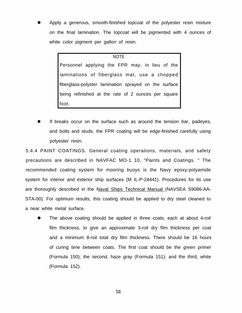
● Apply a generous, smooth-finished topcoat of the polyester resin mixture
on the final lamination. The topcoat will be pigmented with 4 ounces of
white color pigment per gallon of resin.
NOTE
Personnel applying the FPR may, in lieu of the
laminations of f iberglass mat, use a chopped
fiberglass-polyster lamination sprayed on the surface
being refinished at the rate of 2 ounces per square
foot.
● If breaks occur on the surface such as around the tension bar, padeyes,
and bolts and studs, the FPR coating will be edge-finished carefully using
polyester resin.
5.4.4 PAINT COATINGS. General coating operations, materials, and safety
precautions are described in NAVFAC MO-1 10, “Paints and Coatings. ” The
recommended coating system for mooring buoys is the Navy epoxy-polyamide
system for interior and exterior ship surfaces (M IL-P-24441). Procedures for its use
are thoroughly described in the Naval Ships Technical Manual (NAVSEA S9086-AA-
STA-00). For optimum results, this coating should be applied to dry steel cleaned to
a near white metal surface.
● The above coating should be applied in three coats, each at about 4-roil
film thickness, to give an approximate 3-roil dry film thickness per coat
and a minimum 8-roil total dry film thickness. There should be 16 hours
of curing time between coats. The first coat should be the green primer
(Formula 150); the second, haze gray (Formula 151); and the third, white
(Formula 152).
58
● The two components of all MI L-P-24441 coatings should be mixed in
equal volume by first thoroughly stirring each component separately and
then stirring them together. After mixing, there should be a waiting
period of about 2 hours at 500 to 60°F; 1 to 1 1/2 hours at 60° to 70°F;
and 1/2 to 1 hour above 70° before applying the coating to ensure
complete curing later. The mixed paints do not require thinning, but the
low temperature application properties can be improved by adding 10
percent, by volume, of a mixture of equal parts of n-butyl alcohol and
AMSCO Super High Flash Naphtha, or an equivalent mixture.
Usual paint spray equipment, either conventional or airless, can be used. The pot
life of the mixed coating is about 6 hours at 73°F. If more than 7 days elapse
between epoxy coats, the surface should be cleaned with water and detergent,
rinsed with fresh water, dried, and then a tack coat (1 to 2 roils wet film thickness) of
the last coat applied before application of the next full coat.
The above coating system, when properly applied, will provide at least 3 to 5
years of protection, depending upon the severity of the environment. Experience
has shown that an antifouling paint is usually unnecessary because fouling will not
damage the coating, add a significant amount of weight to the buoy, or otherwise
adversely affect the mooring. In addition, the effective life of antifouling paint is
usually much shorter than the time between buoy overhauls, so that significant
fouling will still occur before the next overhaul. Should an antifouling paint be
desired for the underwater portion of the buoy, MIL-P-15931, Formula 121/63,
applied in two coats, is recommended. The antifouling paint, which is red, must be
applied while the topcoat of epoxy (M IL-P-24441, Formula 152) is still tacky (within 4
to 6 hours after its application). If the epoxy has hardened, a tack coat (1 to 2 roils
wet film thickness) must be applied and allowed to cure for 4 hours before the first
coat of antifouling paint is applied.
5 9

5.4.5 QUALITY OF WORK. All of the workmanship on the coating systems shall be in
accordance with the Naval Ships Technical Manual, NAVSEA S9086-AA-STM-000.
The work shall be performed by or under the immediate and direct supervision of
skil led personnel who have demonstrated a continuing proficiency in the
application of multilayered coatings on extensively contoured areas similar and
comparable to the exterior of mooring buoys. Quality of workmanship shall meet
the highest standards asset forth in the specifications and manuals noted herein.
60

6.0 ASHORE INSPECTION AND REFURBISHMENT OF CHAIN AND ACCESSORIES
6.1 GENERAL
6.1.1 SCOPE. The purpose of inspecting chain and accessories is to make a sound
qualitative decision as to the disposition of these items. There are two types of
inspections: preliminary and detailed. The preliminary inspection is performed in
the known wear areas and will determine whether the chain and accessories are in
adequate condition for continued use, whether a detailed inspection is required, or
whether the items should be disposed of. In the detailed inspections, each link of
chain and each accessory is thoroughly inspected for corrosion, cracks, wear, pitting,
elongation, or other abnormalities. Based on the results of this inspection, a
decision is made either to refurbish and retain the material or to dispose of it.
6.2 INSPECTION AND REFURBISHMENT
6.2.1 PRELIMINARY INSPECTION. Before commencing the inspection, the chain
assembly will be disassembled into individual shots or into the shortest whole chain
lengths. The ground ring, swivels, joining links, and shackles will be removed.
Shackles and joining links should be kept together as complete units, including pins.
Shackle pins and tapered locking pins should be used only in their original parent
component. Preliminary inspection will include the following:
● Visually inspect all accessories and chain for abnormal wear,
deformation, cracks, or missing studs. Studs should not be removed from
chain links for any reason. Links found without studs should be cut from
the length of chain and discarded.
● Take single or double link measurements (as described in Paragraph
6.2.2) in known or suspected high wear areas, such as the first two to
four links on each end of a shot, the wear zone on each anchor leg
assembly (where the chain links are shiny), and components used in the
riser subassembly or used as buoy jewelry.
61

● Classify chain and accessories as good, fair, or poor according to the
criteria described in Paragraph 6.2.2 below. All material in good or fair
condition will undergo a detailed inspection before it is recoated and
returned to inventory for future use. Any material classified in poor
condition (wire diameter less than 80 percent of original size, cracked or
deformed, etc.) is unsuitable for future use and should be disposed of
through normal channels.
● Isolated links in poor condition may be cut from a length of chain to
salvage the usable portion. In such cases the remaining links must all be
carefully examined during the subsequent detailed inspection.
6.2 .2 DETAILED INSPECTION. After the preliminary inspection, (if it is
recommended that a detailed inspection be performed), the chain will be
sandblasted in accordance with the latest edition of the “Steel Structures Painting
Manual, Vol. II, Systems and Specifications, ” Specification SSPC-SP-6. Detailed
inspection of chain and its accessories will include the following:
● Take single link caliper measurements of the wear areas at the ends of
the chain links and accessories (anchor joining links, shackles, chain
joining links, etc. (see Figure 6-l). The condition of the chain will be
determined as follows:
CONDITION AMOUNT OF DETERIORATION
Good 90% or greater of original wire diameter measured.
Fair 80-90% of original wire diameter measured.
Poor 80% or Iess of original wire diameter measured.
● Carefully inspect each accessory or chain link for cracks, corrosion,
elongation or other deformations, and other abnormalit ies. Any
6 2

Figure 6-1. Location of Caliper Measurements of Wear Areas In Chain and
Accessories
63

●
●
●
●
components containing cracks, deformations, or severe localized
corrosion will be classified in “poor” condition.
Material in good or fair condition should be recoated, tagged, and
returned to the inventory for use. Material in poor condition is
unsatisfactory for use in fleet moorings and should be discarded.
Isolated links in poor condition may be cut from a length of chain to
salvage the portions in good or fair condition.
Keep shackles and joining links together as complete units (including
pins).
Coat the mating surfaces of the joining links and swivels with a
molybdenum disulfide grease (M IL-G-23549) or an equivalent lithium
based grease. The results of all inspections (both preliminary and
detailed) will be fully documented and filed for future reference.
Inspection results should be used in planning and estimating future
repair or replacement requirements and associated labor costs.
6.2.3 PROTECTIVE COATINGS. Application of protective coatings should be
performed as follows:
● Spray, dip, or brush the abrasive blasted chain with an approved rust
preventative (MI L-C-16173 Grade 11 1).
● Place the chain on a clean surface to dry.
NOTE
Coating operations should be avoided on cold,
damp days.
64
7.0 ASHORE INSPECTION AND REFURBISHMENT OF ANCHORS
7.1 GENERAL
7.1.1 SCOPE. Anchors for fleet moorings generally require very little maintenance
and are seldom subject to failure. Although little maintenance is expected, this
chapter will cover the maintenance checks that should be performed whenever an
anchor is removed from service. Maintenance will encompass inspections, tests, and
repairs of the anchors.
7.2 INSPECTION AND REFURBISHMENT
7.2.1 GENERAL. The primary purpose of inspecting an anchor is to determine its
general physical condition and its suitability for reuse. The inspection of an anchor
should only be conducted when the anchor is either temporarily aboard a barge or
in a storage area ashore. There are two types of anchor inspections: preliminary,
which can be conducted either aboard a barge or ashore, and detailed, which is
normally conducted ashore. These inspections should be accomplished as soon as
possible after the anchor is removed from the water.
7.2.2 PRELIMINARY INSPECTION. The purpose of a preliminary inspection is to
determine whether an anchor is in satisfactory condition for continued operational
use. If abnormalities are found and the condition of the anchor is suspect, then a
detailed inspection of the anchor is performed. The preliminary inspection of an
anchor will include the following:
● Clean the anchor with a stream of water from a high-pressure hose.
● Take at least two caliper measurements of the wire diameter of the
anchor shackle. One measurement should be taken at the wear zone of
the lugs of the shackle. If the wire diameter of the shackle measures
greater than 90 percent, the shackle is accepted. If the measurement is
90 percent or less, the shackle must be replaced.
65

● Visually check the anchor for casting irregularities, cracks, or obvious
mechanical damage. On STATO, NAVMOOR, and other welded anchors,
all welds should be checked for cracks, fissures, corrosion, or other
defects. If present, stabilizers and their attachment points should be
inspected for cracks or other signs of weakness.
● Conduct a hammer test to determine if there are any invisible cracks or
other abnormalities. To accomplish this test, a crane is required to lift the
anchor off the ground by its anchor shackle. The palm of each fluke is
then struck with a 5-pound (or larger size) hammer. A ringing tone
indicates that there are no abnormalities in the structure of the fluke. A
dull “thump” indicates that the fluke structure contains serious cracks or
other abnormalities.
The results of the above preliminary inspection measurements, observations,
and tests should be documented. If the inspected anchor is determined to be in
satisfactory condition as a result of this inspection, no further effort will be
expended, and the anchor will be made ready for further use or placed in a
designated storage area.
7.2.3 DETAILED INSPECTION. This inspection will be conducted only if, as a result of
the preliminary inspection, abnormalities are suspected or if the condition of the
anchor is questionable. The detailed inspection will include the following:
● Clean anchor by sandblasting to near white metal.
● Visually inspect anchor for cracks or casting irregularities. Pay particular
attention to anchor flukes and welds.
● Perform a liquid dye penetrant or magnetic particle test on any
suspected cracks or abnormalities in accordance with MIL-STD-271, "Non-
Destructive Testing Requirements for Metals.”
66
If the results of this testing indicate that cracks or other abnormalities do exist,
a decision will have to be made to determine if these abnormalities can be corrected
by grinding and welding or if they are too numerous or too deep for economical
refurbishment of the anchor. If repairs can be made, then as soon as they are
accomplished, the anchor should be protectively coated with a black-gloss solvent-
type paint (MI L-P-2430). If it is determined that refurbishment of the anchor is not
economically feasible, then the anchor may be retained in storage for future use as
a sinker/clump or disposed of. All findings/results of the detailed inspection shall be
fully documented and filed.
67

8.0 CATHODIC PROTECTION SYSTEMS
8.1 GENERAL
8.1.1 SCOPE. Shore activities responsible for the operation and maintenance of
fleet moorings expend considerable time and money maintaining moorings in a
safe, reliable condition. The highly corrosive effect of seawater necessitates a
continuous program of preventive and corrective maintenance. The frequency of
maintenance actions is directly related to the rate of corrosion and wear of the
mooring chain and other components. Recent analysis of the maintenance of fleet
moorings, with and without cathodic protection over extended periods of time,
indicates that the use of an effective cathodic protection system (CPS) can
significantly reduce the corrosion rate of mooring chain, yielding an attendant
savings in maintenance costs.
8.1.2 APPLICATION. Cathodic protection of steel submerged in seawater is achieved
by impressing a negative electrical potential on the surfaces exposed to the
seawater. Several systems have been developed to supplement protective coatings
in an effort to reduce corrosion of fleet mooring chain and accessories. Typically,
the required electrical potential is provided by sacrificial zinc anodes which are
gradually consumed while catholically protecting the steel components. Cathodic
protection of the submerged portion of the buoy may also be provided by sacrificial
anodes attached to the hull. Anchors normally do not require cathodic protection
because bottom mud isolates the anchors from the corrosive effects of the
seawater.
8.1.3 EFFECTIVENESS. The cathodic protection system and the protective coatings
on the mooring components work together to keep the underwater portion of the
buoy and the chain assembly from corroding. It is estimated that such a system,
properly installed and maintained, can provide complete protection for IS years in
aggressive environments, and for longer periods at milder locations, before anode
68

replacement becomes necessary. Additional anodes can then be installed without
removal of the mooring. Buoy anodes are not used when the buoy is fiberglass or
polyurethane coated; only the chain and the lower portions of the tension bars on
these buoys must be protected.
8.2 CATHODIC PROTECTION FOR BUOYS
8.2.1 ENVIRONMENTAL CONSIDERATIONS. In designing a cathodic protection
system, the extremes of favorable and unfavorable environmental conditions
should be considered. Favorable local environmental conditions (low salinity,
minimal tide, quiescent water, low dissolved oxygen content, low temperatures,
and moderate currents) result in longer periods of time between preventive or
corrective maintenance. Unfavorable local environmental conditions (high salinity,
high tidal variations, turbulent water, high dissolved oxygen content, high
temperature, and strong currents) increase the wear and corrosion rates and
decrease the time between required maintenance actions. Cathodic protection is
beneficial in all environmental conditions but especially where unfavorable local
conditions exist.
8.2.2 ANODES. Anodes for use on buoys are readily available. One commonly used
is a zinc casting 36 inches long with a nominal cross-sectional area of 16 square
inches. The anode weighs approximately 150 pounds, and is cast on a 48-inch-long
3/4-inch-diameter pipe (see Figure 8-l). The composition of the zinc is in
conformance with MI L-A-18001. Buoy anodes must be secured in a location where
they will not be subjected to impact by vessels; for example, on the bottom of drum-
type buoys, in a sea chest built into core portions of peg-top riser-type buoys, or
within protective cages welded to the conical side of a peg-top buoy. These anodes
should be located about 4 inches from buoy surfaces.
The new foam buoy hulls do not require cathodic protection and, therefore,
anodes are not attached to it. The lower portion of its steel tension bar member,
69

however, is exposed to sea water and must be protected. This is accomplished by
attaching one chain stud anode on either side of the exposed portion of the tension
bar.
Figure 8-1. Buoy Anode
8.2.3 INSTALLATION OF ANODES. Buoy anodes are usually installed while the
buoys are being overhauled ashore. Replacement can also be accomplished at a
mooring site during a regularly scheduled maintenance inspection by lifting the
buoy out of the water and removing and replacing the anodes while the buoy is on
deck. Whether the installation of the buoy anodes are on the bottom, in a sea
chest, or within a protective cage, a pair of angle iron brackets are installed which
will support each buoy anode. The brackets are welded directly to the buoy hull
and generally have threaded fittings for simple anode installation and replacement.
70

The fittings are of clean, unpainted metal to ensure good electrical continuity
between the zinc anode and the buoy hull. Where recessing of the anode is
necessary, the brackets are located in a conveniently sized sea chest built to house
the anode and its fittings (see Figure 8-2). Alternately, protective cages can be
fabricated so as to have sufficient diameter and length to fit over the anode
installation (See Figure 8-3).
8.3 CATHODIC PROTECTION FOR MOORING CHAIN
8.3.1 ANODES. Zinc anodes are used for cathodic protection of mooring chain.
There are basically three types of commercially available sacrificial anodes (zinc
composition conforming with MIL-A-18001). These are chain stud anodes, link
anodes, and clump anodes.
71

Figure 8-2. Buoy Anode Recessed Within a Sea Chest
Figure 8-3. Anode Protective Cage
72
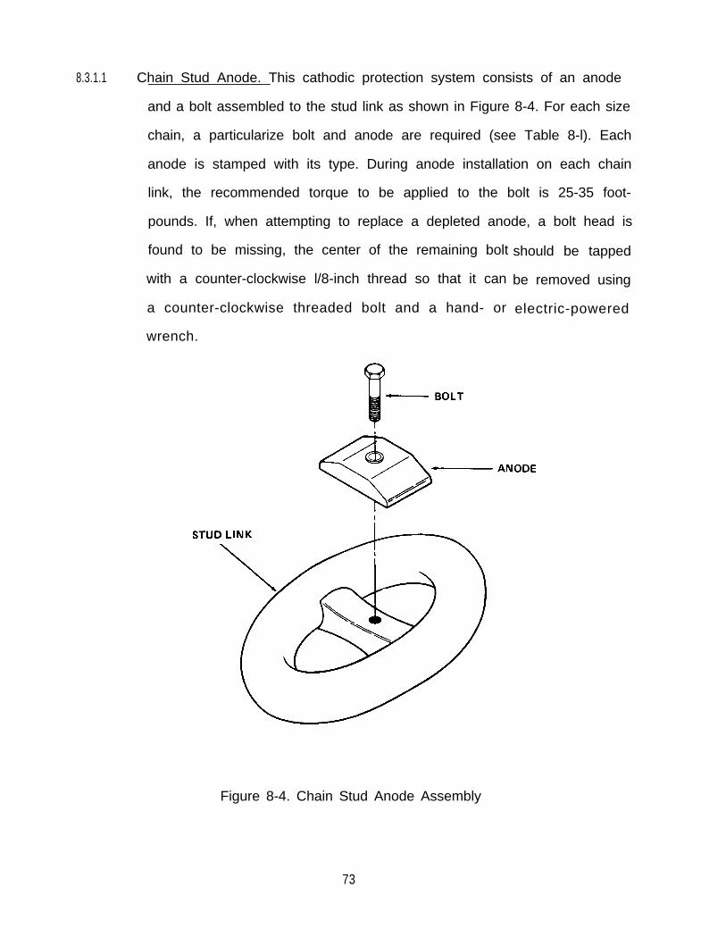
8.3.1.1 Chain Stud Anode. This cathodic protection system consists of an anode
and a bolt assembled to the stud link as shown in Figure 8-4. For each size
chain, a particularize bolt and anode are required (see Table 8-l). Each
anode is stamped with its type. During anode installation on each chain
link, the recommended torque to be applied to the bolt is 25-35 foot-
pounds. If, when attempting to replace a depleted anode, a bolt head is
found to be missing, the center of the remaining bolt
with a counter-clockwise l/8-inch thread so that it can
a counter-clockwise threaded bolt and a hand- or
wrench.
should be tapped
be removed using
electric-powered
Figure 8-4. Chain Stud Anode Assembly
73
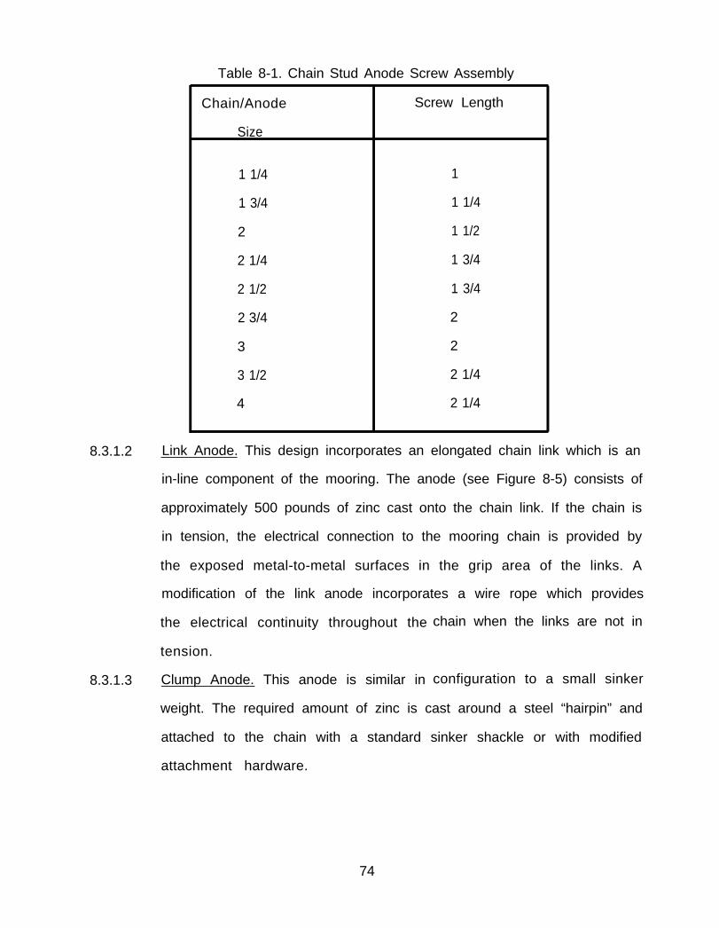
Table 8-1. Chain Stud Anode Screw Assembly
Chain/Anode Screw Length
Size
1 1/4 1
1 3/4 1 1/4
2 1 1/2
2 1/4 1 3/4
2 1/2 1 3/4
2 3/4 2
3 2
3 1/2 2 1/4
4 2 1/4
8.3.1.2 Link Anode. This design incorporates an elongated chain link which is an
in-line component of the mooring. The anode (see Figure 8-5) consists of
approximately 500 pounds of zinc cast onto the chain link. If the chain is
in tension, the electrical connection to the mooring chain is provided by
the exposed metal-to-metal surfaces in the grip area of the links. A
modification of the link anode incorporates a wire rope which provides
the electrical continuity throughout the
tension.
8.3.1.3 Clump Anode. This anode is similar in
chain when the links are not in
configuration to a small sinker
weight. The required amount of zinc is cast around a steel “hairpin” and
attached to the chain with a standard sinker shackle or with modified
attachment hardware.
74

Figure 8-5. Link Anode Design
This anode also requires the use of a wire rope, which is woven through the chain to
provide electrical continuity. Wire clips or hose clamps are used to connect the wire
rope to the anodes and to the chain links.
8.3.2 INSTALLATION. For proper operation of the cathodic protection system, the
anodes, wire ropes, and fittings should be free of paint, grease, dirt, or coatings.
The wire ropes and fittings will be catholically protected by the anodes. A cathodic
protection system installation can be most easily and economically accomplished at
the time of the regularly scheduled mooring overhaul and prior to installation of
the mooring system.
8.3.2.1 Chain Stud Anode. This type anode is attached to each stud in the chain
link. The attachment will normally be accomplished by the chain
manufacturer. However, divers or ashore personnel may be required to
replace missing or deteriorated anodes. Installation requires bolting the
proper anode to the chain link stud as previously shown in Figure 8-4. In
some cases new chain shots may be shipped with the studs drilled for
these anodes, but with anodes not installed. In these cases, the threaded
holes will be lubricated with an electrically conductive graphite lubricant
(VV-G-671) to reduce the probability of corrosion, and the hole fitted
with a steel screw to prevent it from being filled with coating material
(see Figure 8-6). The lubricant will not degrade the cathodic protection
system and does not have to be cleaned out before installing the anode.
75
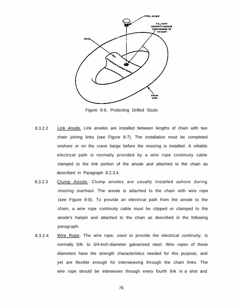
Figure 8-6. Protecting Drilled Studs
8.3.2.2 Link Anode. Link anodes are installed between lengths of chain with two
chain joining links (see Figure 8-7). The installation must be completed
onshore or on the crane barge before the mooring is installed. A reliable
electrical path is normally provided by a wire rope continuity cable
clamped to the Iink portion of the anode and attached to the chain as
described in Paragraph 8.2.3.4.
8.3.2.3 Clump Anode. Clump anodes are usually installed ashore during
mooring overhaul. The anode is attached to the chain with wire rope
(see Figure 8-8). To provide an electrical path from the anode to the
chain, a wire rope continuity cable must be clipped or clamped to the
anode's hairpin and attached to the chain as described in the following
paragraph.
8.3.2.4 Wire Rope. The wire rope, used to provide the electrical continuity, is
normally 5/8- to 3/4-inch-diameter galvanized steel. Wire ropes of these
diameters have the strength characteristics needed for this purpose, and
yet are flexible enough for interweaving through the chain links. The
wire rope should be interwoven through every fourth link in a shot and
76

Figure 8-7. Link Anode Installed in a Chain Section
Figure 8-8. Clump Anode and Chain as Viewed Underwater
77
attached to every eighth link with a hose clamp, wire clip, or U-bolt. Prior to
attaching the continuity wire to the chain link, part of the link must be cleaned to
bare metal so that the chain link and the continuity wire have good metal-to-metal
contact. This is important for a sound electrical connection.
8.3.3 ANODE REPLACEMENT. An anode should be replaced if less than 25 percent
of its original weight remains. Replacement should be accomplished by trained
personnel, and equipment and materials should be on hand, both ashore and on
crane barges, to support this activity. Replacement of chain stud anodes can easily
be handled by divers. However, replacement of in-line link anodes, clump anodes,
and buoy anodes is more difficult for divers. In addition, divers will find it difficult
to replace any anodes in areas where the bottom is muddy or where the anchor
chain subassembly is partially buried.
78

9.0 STORAGE OF MOORING MATERIALS
9.1 GENERAL
9.1.1 GENERAL REQUIREMENTS. Mooring components are usually stored in open
areas near a coastline, thus exposing them to weather and a marine environment.
To prevent deterioration while in storage, some preventive maintenance will be
required in addition to the routine material handling and inventory control tasks
normally performed by a storage facility. The job of handling, maintaining, and
controlling stored components will be made much easier if some basic guidelines, as
noted below, are followed.
●
●
●
●
●
The storage area should be large enough to permit efficient movement
of forklifts, cranes, and other large mobile equipment.
Arrangement of components should allow easy access for inspections,
inventory checks, and selection.
To reduce corrosion, all components except cathodic protection materials
should be coated with paint, approved rust preventatives, coal tar, or
other suitable preservatives as detailed in Chapters 5.0,6.0, and 7.0.
All components should be tagged or Iabelled to ensure proper
identification and accurate inventory reporting.
Chain accessories such as joining links, swivels, ground rings, and shackles
should be crated or banded together on pallets to permit easy handling.
The paragraphs that follow provide additional details and other
considerations for Fleet Mooring Inventory (FMI) storage.
9.1.2 STORAGE AREA REQUIREMENTS. Shore activities requiring spare mooring
materials and those activities designated as stock points for the FM I will require a
suitable storage area. The following should be observed:
● The FMI should normally be stored in a secure area designated by activity
personnel responsible for space allocation.
79

● The storage area should be on solid ground or on improved surfaces, and
graded for drainage.
● The area should be large enough, as well as configured, to allow easy
access of equipment and personnel involved in chain handling and other
maintenance operations.
● The area should be close to maintenance areas, transportation
equipment, and the waterfront to reduce both maintenance and
transportation costs.
9.2 STORAGE PROCEDURES
9.2.1 BUOYS. Store buoys as follows:
● Place all drum type buoys on chocks or dunnage, with all metal parts
clear of the ground, and tilted (using additional chocks or dunnage
under one side) to facilitate water runoff.
● Store peg-top buoys in an inverted position (see Figure 9-l).
Buoys should be periodically inspected to aid in the detection and prevention
of localized corrosion areas. If corrosion is found, corrective action should be
implemented. Corrosion commonly develops in the web of channel irons securing
wooden fenders, in the hull behind rubber fendering, and on the nuts/studs used to
secure manhole covers, fenders, and chafing strips. Ground or chock contact points
are also susceptible to higher corrosion rates. Any area on the top of the buoy that
could collect water is susceptible to accelerated corrosion.
9.2.2 CHAIN AND CHAIN ACCESSORIES. Chain is normally stored ranged out in
tiers, bailed a single shot at a time on a pallet, loaded in shipping crates, or in
bundles. The ground where the chain is stored should be clear of all debris and
80

Figure 9-1. Proper Storage of a Peg Top Buoy
growth, and well drained. To prevent its intermixing with older grades of chain, FM
3 chain and accessories should always be stored separately.
9.2.2.1 Tiered Chain. Store chain in tiers as follows:
● Lay chains down stretched out taut and free of turns.
● Pile tiers in multiple layers to reduce storage space (see Figure 9-2).
● Each tier should contain chain of similar construction, size, and
condition for ease of access and accurate inventory control.
● The ends of each length of chain should have an identification tag
attached to it which contains the chain size (in inches), type
(cast/forged/etc.), length (in feet), and manufacturer.
9.2.2.2 Palletized Chain. Chain may also be stored and handled on pallets.
Normally, chain is palletized in single shot lengths to reduce handling
weights and to simplify inventory. Chain pallets normally consist of
wooden or steel pallets onto which the chain is piled.
81

9.2.2.3 Crated Chain.
Figure 9-2. Chain Stored in Tiers
Reusable wooden crates can be used for the shipment and
storage of chain and will normally contain a single shot of chain. The
crates can be stacked to reduce deck space requirements if not loaded
beyond the design capacities stamped on the crates (see Figure 9-3). Five
standard-sized crates have been constructed for the various chain sizes.
The design of one of these crates is shown in Figure 9-4.
9.2.2.4 Bundled Chain. Chain will be bundled by reeving wire rope through the
last link on each end of the shot and through two other Iinks, each
approximately 30 feet from the nearest end of the shot. The ends of the
wire rope shall be secured to each other to form a sling which may be
used to lift the entire shot. When Iifted, the total length of the shot/sling
combination shall not exceed 20 feet.
9.2.2.5 Accessories. Accessories should be boxed, crated, or banded to pallets.
Components of the same size, type, and condition should be stored
together for inventory control and ease of access. Parts for joining links
82
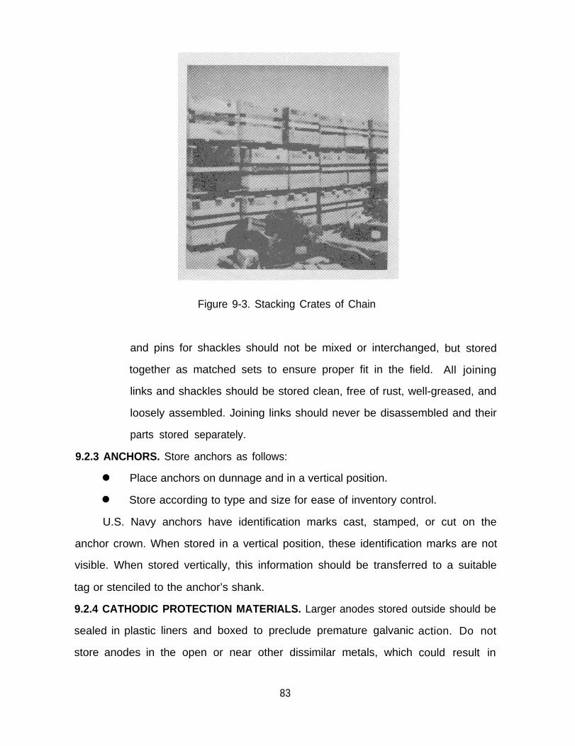
Figure 9-3. Stacking Crates of Chain
and pins for shackles should not be mixed or interchanged,
together as matched sets to ensure proper fit in the field.
but stored
All joining
links and shackles should be stored clean, free of rust, well-greased, and
loosely assembled. Joining links should never be disassembled and their
parts stored separately.
9.2.3 ANCHORS. Store anchors as follows:
● Place anchors on dunnage and in a vertical position.
● Store according to type and size for ease of inventory control.
U.S. Navy anchors have identification marks cast, stamped, or cut on the
anchor crown. When stored in a vertical position, these identification marks are not
visible. When stored vertically, this information should be transferred to a suitable
tag or stenciled to the anchor’s shank.
9.2.4 CATHODIC PROTECTION MATERIALS. Larger anodes stored outside should be
sealed in plastic
store anodes in
liners and boxed to preclude premature galvanic
the open or near other dissimilar metals, which
action. Do not
could result in
83

Figure 9-4. Overseas Shipping Container for 3 1/2- and 4-inch Chain(14,000 lb. Capacity)
84
corrosion of the anodes. Chain stud anodes should be stored in 55-gallon steel
drums with removable, bolt-on type lids. Only one size of anode shall be packed in
each drum. Cathodic protection material should be kept clean and should not be
painted or coated with oil or grease during either storage or use.
9.2.5 MARKING AND IDENTIFICATION. Marking and identification of components
will be accomplished as described below.
9.2.5.1 General. Proper marking and identification of all mooring components
will assist in conducting inventories, will help prevent use of improper or
substandard materials, and will speed assembly and installation times
when required components must be drawn from inventory.
9.2.5.2 Color Coding. It is also good practice to color code chain to identify its
condition. Recommended colors to be applied to the last link on each
end of a chain length are:
● Green - for chain in new or good condition.
● Yellow - for chain in fair condition.
● Red - for chain in poor condition and ready for disposal.
9.2.5.3 Identification. Identification of chain and accessories shall be on tags of
0.031-inch thick aluminum alloy 1100 or 3003, attached using 0.031-inch
diameter 300 series corrosion resisting steel wire through 0.125-inch
diameter holes at each end of the tag. Characters shall be metal stamped
using 0.25-inch high characters. Tag size and information content shall
be as specified in Figure 9-5. On chain shots, tags shall be attached to the
last link on each end of the shot. Tags will be attached snugly to each
accessory in a location away from the grip area of the component, and
shall be bent to conform to the contour
risk of snagging or damaging the tag.
of the component to minimize
85

9.2.5.4
EXAMPLE TAG
Figure 9-5. Shipping Tag
Chain and Accessories. Chains and accessories are marked and identified
as follows:
● The size and the name of the manufacturer are stamped or forged
on each chain link or accessory during manufacture.
● New FM 3 chain will also have a unique serial number on each
accessory and on the links at the end of each shot of chain (see
Figure 9-6). The serial number will be used together with
documentation furnished by the manufacturer (heat number,
chemical composition, etc. ) to monitor the pe
different heats of chain.
● Crates used to ship new chain and accessor
manufacturer will be marked to show:
Contents,
Weight,
Contract and shipping data, and
Stacking limitations.
Contents, etc.
rformance of
ies from the
86

An artist’s drawing of an overseas shipping container for chain
accessories is depicted in Figure 9-7.
Figure 9-6. Chain Markings
Figure 9-7. Overseas Shipping Container for Chain Accessories (3000 lb. Capacity)
87
9.2.5.5 B U O Y S. New buoys should have an identification plate showing the
following:
● Serial number,
● Manufacturer,
● Date of manufacture,
● Diameter,
● Height,
● Weight in air,
● Maximum tension bar load, and
● NAVFAC drawing number.
This plate should be protected during sandblasting and should not be
painted or coated.
9.2.5.6 Anchors. Identification information for anchors is cast on the crown, on
the flukes, or on the side of the shank. Minimum information provided is
as follows:
● Manufacturer,
● Weight, and
● Serial number.
9.2.6 PRE-ISSUE INSPECTION. Items that are issued from inventory should be
inspected prior to shipping or movement from the storage facility. A bill of material
should be reviewed to ascertain the components required and a check of all
material sizes accomplished. To ensure all mooring components fit when shipped to
the field, a physical fit check should be accomplished prior to shipment. The many
configurations and designs of mooring hardware increase the likelihood of a misfit
if a physical fit check is not accomplished.
88

APPENDIX A
REFERENCES
A-1
1.1
1.2
1.3
NAVFAC DESIGN MANUALS
TITLE
DM-7 Soil Mechanics, Foundations, and Earth Structures
DM-26.3 Coastal Sedimentation and Dredging
DM-26.4 Fixed Moorings
DM-26.5 Fleet Moorings
DM-26.6 Mooring Design Physical and Empirical Data
DM-35 Drydocking Facilities
NAVFAC MAINTENANCE ORDERS
TITLE
MO-110 Painting and Protective Coatings
NAVAL SHIPS TECHNICAL MANUALS
TITLE
NAVSEA S9086-AA-STM-000 Naval Ships Technical Manual (latest revision):
Chapter 581, Anchors and Anchoring; Chapter 050,
Readiness and Care of Vessels in Inactive Status;
and Chapter 631, Preservation of Ships in Service
1.4 NAVFACENGCOM PUBLICATIONS
TITLE
NAVFACENGCOM P-71 5.0 EPS Wharf building Handbook (T R-Service)
(November 1979)
1.5 NATIONAL BUREAU OF STANDARDS
TITLE
-- Organic Coating properties, Selection and Use;
Building Science Series 7 (February 1968)
A-2

1.6 OTHER PUBLICATIONS
TITLE
Keane, John D., “Steel Structures Paint ing
Manuals, ” Volume 2, “Systems and Specifications, ”
(latest edition) Steel Structures Painting Council,
Pittsburgh, Pennsylvania
Book of Standards (latest revision), American Wood
Preservers’ Association, Washington, D.C.
deBoer, F. L., “Fiberglass Coat ings for Fleet
Moorings,” Navy Civil Engineer, pp. 16-17 (March
1970)
Rules for Building and Classing Steel Vessels (latest
edition), American Bureau of Shipping, New York,
New York
Rules for Building and Classing Single Point
Moorings, American Bureau of Shipping, New York,
New York (1975)
A-3
APPENDIX B
MOORING COMPONENTS
B-1
APPENDIX B
MOORING COMPONENTS
1.1 GENERAL. This appendix discusses the various types of fleet mooring material
components currently in use and describes their distinctive
characteristics. For clarity, sketches of these components are included (all figures
may be found at the end of this appendix).
1.2 FLEET MOORING BUOYS. The size of the buoy used in a particular fleet mooring
is dependent on the depth of the water and the weight of the chain suspended in
the water column. Figure B-1 shows the four types of buoys commonly used in fleet
moorings.
1.2.1 BUOY SYSTEMS. Buoy systems fall into two categories, riser and non-riser-
types, depending upon the configuration of the ground tackle securing them to the
sea floor. Riser-type systems have a single point at the center of the bottom of the
buoy to which a riser chain is attached. The non-riser-type system has a larger buoy
with three to four padeyes attached to its circular bottom edge. Each of these
padeyes is attached to one or more anchor leg subassemblies.
1.2.2 BUOY TYPES. The following types of buoys are currently utilized in fleet
moorings:
1.2.2.1 Drum BUOY. This buoy is normally made of steel and is available in a
variety of sizes.
primarily used in
has a paint or
polyurethane coating. This type of buoy contains either a tension bar or
a hawsepipe (see Figure B-l).
● Tension Bar. A tension bar is a steel bar which passes through the
center of the buoy with padeyes on top and bottom. The new
The shape of the buoy resembles a drum, and it is
smaller classes of moorings. The older standard design
fiberglass coating while the newer design has a
B-2
foam buoy has a 10-inch diameter pipe used as a tension bar. The
lower padeye is connected to the upper link of the riser chain. A
moored vessel can be connected to the upper padeye by its anchor
chain, wire rope, or mooring hawsers.
● Hawsepipe. A hawsepipe is a cylindrical tube passing through the
center of the buoy. The riser chain is passed through this tube and
its upper Iink is held on the top of the buoy with a slotted chain
plate. The lower portion of the riser chain within the hawsepipe is
protected from wear by a rubbing casting which encircles the chain
and greatly reduces the probability of chain abrasion. A moored
vessel ties directly to the riser chain. The buoy is nonstructural in
that the mooring load passes through the buoy via the riser chain.
1.2.2.2 Peg Top Buoy. This buoy is also used to support riser-type moorings, and
includes either a tension bar or hawsepipe. Peg top buoys are conically
shaped, with the top deck area considerably larger than the bottom
surface (See Figure B-l).
1.2.2.3 Non-Riser-Type Buoy. These buoys are larger than those used in riser-
type moorings since they have the additional weight of three or more
ground legs to support in the water column. These buoys have a swivel
at the top to which the moored vessel’s anchor chain or hawser is
attached. Three or four padeyes, to which the anchor leg assemblies are
connected, are equally spaced around the buoy’s hull (see Figure B-l).
1.2.2.4 Foam Buoy. This is the latest buoy design approved by the Navy. The
buoy consists of a tension bar encompassed by a rigid closed-cell interior
foam which is covered by a flexible cross-linked polyethylene foam
adhered to the rigid interior foam. The overall foam buoy is encased
B-3

within a minimum of a 3/4-inch thick aliphatic urethane elastomer shell
(see Figure B-l).
This buoy is vastly superior to the older steel formed buoy in that:
●
●
●
●
●
If its outer hull is punctured, it will not flood and sink.
It is considerably lighter than the steel buoy required to support a
comparable weight in the water column.
It requires minimum preventative and corrective maintenance.
Its resilient construction greatly reduces the probability of damage
caused by collision with mooring ships.
The projected operational maintenance costs are considerably less
than those of the standard steel buoy.
1.3 CHAIN AND CHAIN ACCESSORIES. Mooring chain not only secures the buoy in a
predetermined position, but its weight also serves to absorb energy caused by the
dynamic motion of moored vessels. Chain is usually manufactured in 15-fathom (90-
foot) lengths, called shots. The chain diameter required for a particular mooring
will vary depending on the anticipated maximum load. Mooring chain links
normally have center crossbars, called studs, to retain the original shape of the link
and to prevent the chain from kinking when it is piled in a heap. The wire diameter
of fleet mooring chain links normally varies from 1-3/4 to 4 inches.
1.3.1 CHAIN TYPES. Chain currently manufactured consists of cast, dilok, or flash
butt-welded links. Figure B-2 contains schematic drawings of these three types of
chain links.
1.3.1.1 Cast Chain. A distinctive feature of this type of chain is that the studs are
solid and cast integrally with the links. Cast chain is also made to
commercial link standard dimensions.
1.3.1.2 Dilok Chain. A dilok link, which is chiefly used in a ship’s anchor chain,
and not fleet moorings, is made of two forged U-shaped pieces. A
B-4

forged stem of one piece (the male) contains a series of parallel
serrations giving an appearance of concentric rings. The other socket
piece (the female) has holes at each end. in joining the two pieces to
form a link, the pierced socket section is heated, then the stems of the
other section are inserted into the holes. The socket section is then
forged with a drop hammer, forcing its material around the indentations
in the other piece’s stems, while both pieces are held in die blocks (see
Figure B-3). Each chain link is made to commercial link standard
dimensions, which are 6 wire diameters long by 3.6 wire diameters wide.
1.3.1.3 Flash Butt-Welded Chain. Each link of this chain is formed by bending a
heated rod into an open chain link shape and flash welding the two butt
ends. While the link is still hot, a stud is inset-ted and the link is pressed
on both sides to secure the stud. After cooling, one or both ends of the
stud may be welded to the link (see Figure B-4).
1.3.2 CHAIN GRADES. The properties of the steel used in the manufacture of chain
for the Navy follow specifications that are similar to the rules followed in the
manufacture of commercial chain. For commonly available chain, there are three
different material qualities designated: Grades 1, 2, and 3, respectively. Grade 3
(which is used as FM 3 chain) has the highest strength of the three and is the grade
currently being procured by the Navy for fleet mooring use and is singularly suited
for application of a cathodic protection system. Figure B-5 depicts a comparison of
the breaking strengths of these different materials.
B-5
1.3.3 CHAIN ASSEMBLY ACCESSORIES.
1.3.3.1 Chain Joining Link. This link is also called a detachable joining link, a
chain connecting link, a detachable link, a Iugless joining shackle, a
detachable connecting link, or a Kenter shackle. This link is used to
connect two shots of chain, two A-links, a swivel and an A-link, etc. Its
wire diameter should be the same size as the mooring components it
connects. The two chain joining links commonly found in the Fleet
Mooring Inventory are the Baldt and Kenter types, named after the
companies which developed their designs. Figures B-6 and B-7 provide
sketches of and dimensional information concerning the Baldt and
Kenter designs, respectively. Procedures for assembling a Kenter type
chain joining link are contained in Appendix D.
1.3.3.2 Anchor Joining Link. This link is also called a detachable anchor
connecting link. This component joins the end of a chain composed of
common links to any of various enlarged mooring components, such as a
ground ring, a buoy padeye, an end link, or an anchor shackle. Figures B-
8 and B-9 provide sketches of and dimensional information for the Baldt
and Kenter types of anchor joining links.
1.3.3.3 Shackles. Although there are many types of shackles available and in use
throughout industry, there are four basic types of shackles used in fleet
moorings:
● Joining Shackle. This shackle is also called a D-link, a D-shackle, or a
joining shackle, “D” type, and is used to connect lengths of chain.
The shackle is similar in shape to an anchor joining shackle but
smaller in size. Figure B-10 provides a schematic of a typical joining
shackle and a dimensional table of its various sizes.
B-6
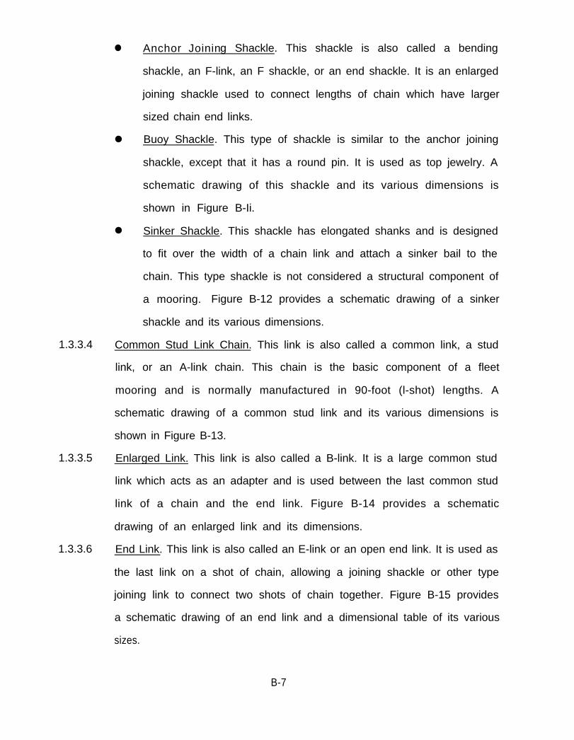
● Anchor Joining Shackle. This shackle is also called a bending
shackle, an F-link, an F shackle, or an end shackle. It is an enlarged
joining shackle used to connect lengths of chain which have larger
sized chain end links.
● Buoy Shackle. This type of shackle is similar to the anchor joining
shackle, except that it has a round pin. It is used as top jewelry. A
schematic drawing of this shackle and its various dimensions is
shown in Figure B-Ii.
● Sinker Shackle. This shackle has elongated shanks and is designed
to fit over the width of a chain link and attach a sinker bail to the
chain. This type shackle is not considered a structural component of
a mooring. Figure B-12 provides a schematic drawing of a sinker
shackle and its various dimensions.
1.3.3.4 Common Stud Link Chain. This link is also called a common link, a stud
link, or an A-link chain. This chain is the basic component of a fleet
mooring and is normally manufactured in 90-foot (l-shot) lengths. A
schematic drawing of a common stud link and its various dimensions is
shown in Figure B-13.
1.3.3.5 Enlarged Link. This link is also called a B-link. It is a large common stud
link which acts as an adapter and is used between the last common stud
link of a chain and the end link. Figure B-14 provides a schematic
drawing of an enlarged link and its dimensions.
1.3.3.6 End Link. This link is also called an E-link or an open end link. It is used as
the last link on a shot of chain, allowing a joining shackle or other type
joining link to connect two shots of chain together. Figure B-15 provides
a schematic drawing of an end link and a dimensional table of its various
sizes.
B-7
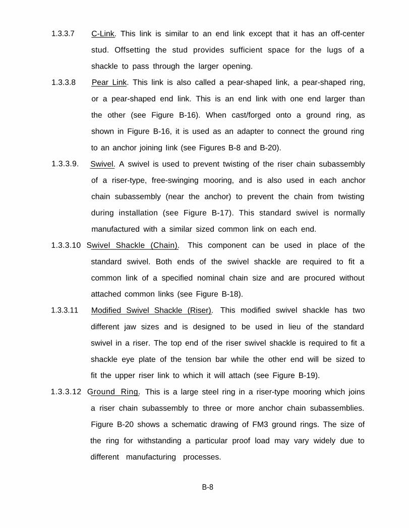
1.3.3.7 C-Link. This link is similar to an end link except that it has an off-center
stud. Offsetting the stud provides sufficient space for the lugs of a
shackle to pass through the larger opening.
1.3.3.8 Pear Link. This link is also called a pear-shaped link, a pear-shaped ring,
or a pear-shaped end link. This is an end link with one end larger than
the other (see Figure B-16). When cast/forged onto a ground ring, as
shown in Figure B-16, it is used as an adapter to connect the ground ring
to an anchor joining Iink (see Figures B-8 and B-20).
1.3.3.9. Swivel. A swivel is used to prevent twisting of the riser chain subassembly
of a riser-type, free-swinging mooring, and is also used in each anchor
chain subassembly (near the anchor) to prevent the chain from twisting
during installation (see Figure B-17). This standard swivel is normally
manufactured with a similar sized common link on each end.
1.3.3.10 Swivel Shackle (Chain). This component can be used in place of the
standard swivel. Both ends of the swivel shackle are required to fit a
common link of a specified nominal chain size and are procured without
attached common links (see Figure B-18).
1.3.3.11 Modified Swivel Shackle (Riser). This modified swivel shackle has two
different jaw sizes and is designed to be used in lieu of the standard
swivel in a riser. The top end of the riser swivel shackle is required to fit a
shackle eye plate of the tension bar while the other end will be sized to
fit the upper riser link to which it will attach (see Figure B-19).
1.3.3.12 Ground Ring. This is a large steel ring in a riser-type mooring which joins
a riser chain subassembly to three or more anchor chain subassemblies.
Figure B-20 shows a schematic drawing of FM3 ground rings. The size of
the ring for withstanding a particular proof load may vary widely due to
different manufacturing processes.
B-8

1.3.3.13 Spider Plate. This is a steel pIate or casting, triangular in shape, that has
three or more holes for joining several chains together (see Figure B-21).
1.3.3.14 Chain Equalizer. The equalizer is a half-rounded type of fitting (similar
to a nonmovable pulley) with wide jaws through which an anchor chain
subassembly is passed and then connected to two separate anchors.
When tension is applied to the mooring, the chain has free movement to
slide through the equalizer until the loads are equal in both subassembly
legs (see Figure B-22).
1.4 ANCHORS. Fleet moorings are held in place by some type of bottom anchoring
system. The types described below are normally used for this purpose.
1.4.1 NAVY STANDARD STOCKLESS. These anchors are used extensively in fleet
moorings primarily because of their availability. However, they are prone to rotate
after reaching their maximum holding power, which results in a pullout. To reduce
the possibility of rotation, stabilizers are often welded to the anchor. The older
type stabilizers consisted of a 1-inch wall-thickness pipe of variable diameters. A
newly designed l/2-inch wall-thickness square tube (NAVFAC Drawing No. 1404456)
will be used for future stabilizers (see Figure B-23). Navy standard stockless anchors
range in size from 500 to 40,000 pounds.
1.4.2 NAVFAC STATO. These anchors were developed for the Naval Facilities
Engineering Command as permanent mooring-type anchors. The stabilizers have
been designed and tested for maximum stability (see Figure B-23). The angle
between the shank and the flukes is adjustable in the field to a 34-degree angle or a
50-degree angle for operations in sand and mud, respectively. STATO anchors
range in size from 200 to 15,000 pounds.
1.4.3 NAVMOOR ANCHOR. This is a prototype anchor being designed for primary
use in fleet moorings vice ships. Its holding power is considerably higher than other
anchors.
B-9

1.4.4 STAKE PILES. This type of anchoring system which consists of wood or steel
pilings driven into the bottom can be used in certain moorings as an anchor. The
disadvantages of this type system are that the stake pile is fixed and cannot absorb
shock energy as well as an anchor, and that a pile-driving rig is required for
installation.
1.4.5 PEARL HARBOR ANCHOR. This anchor is essentially a concrete sinker with a
wedge shape (see Figure B-23). It is relatively inexpensive to build and can be
fabricated onsite. The size and weight required to obtain adequate holding power,
however, make the anchor bulky and difficult to handle.
1.4.6 PROPELLANT-EMBEDMENT ANCHOR (PEA). This relatively new anchor has
been utilized in a number of recent mooring installations. An anchor fluke is
emplaced in a gun assembly. The entire assembly, consisting of the gun (launch
platform), downhaul cable, and anchor fluke (see Figure B-24), is lowered to the
bottom. The gun is then fired and the fluke, depending upon the material of the
ocean bottom, is driven 10 to 40 feet into the subsurface strata (see Figure B-25).
Attached to the fluke is a wire rope downhaul cable (2 to 3 inches in diameter). The
upper end of this downhaul cable is then connected to a wire rope pendant and the
anchor chain subassembly or is directly connected to the anchor chain subassembly
by swage and shackle fittings. The gun assembly is recovered for re-use. A
photograph of a propellant-embedment anchor being prepared for installation is
shown in Figure B-26.
1.5 CATHODIC PROTECTION SYSTEMS. Cathodic protection is an electrical method
of preventing corrosion of metallic structures in a conducting medium (usually
water or soil) by placing an electrical charge upon them. The charge is supplied by
direct current from an anode that consumes itself (sacrificially) in generating the
current or by rectified alternating current. Cathodic protection systems are
discussed in Section 8 of this manual.
B-10
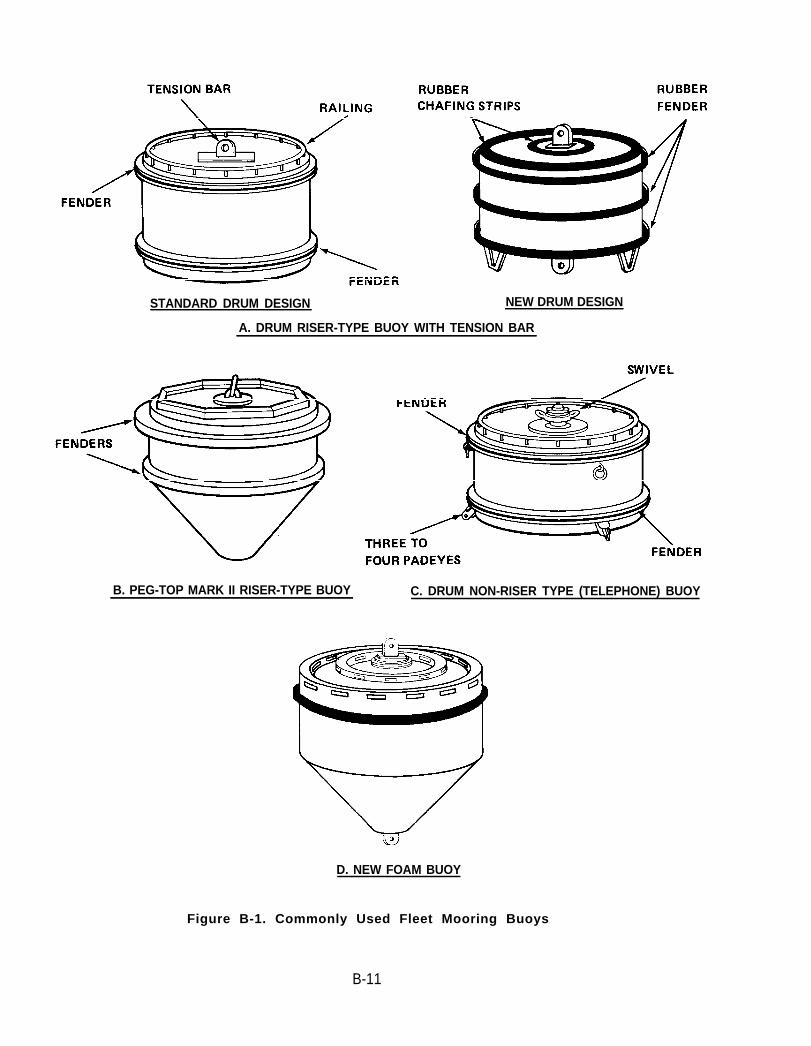
STANDARD DRUM DESIGN NEW DRUM DESIGN
A. DRUM RISER-TYPE BUOY WITH TENSION BAR
B. PEG-TOP MARK II RISER-TYPE BUOY C. DRUM NON-RISER TYPE (TELEPHONE) BUOY
D. NEW FOAM BUOY
Figure B-1. Commonly Used Fleet Mooring Buoys
B-11

Figure B-2. Typical Chain Links
Figure B-3. Manufacturing Dilok Chain
B-12

2 The heated blank is bent intothe chain.
Figure B-4.
5 The drop forged stud is rigid-ly fixed by hydraulic pres-sure while the link is still hot.
Producing Flash Butt-Welded Chain
B-13
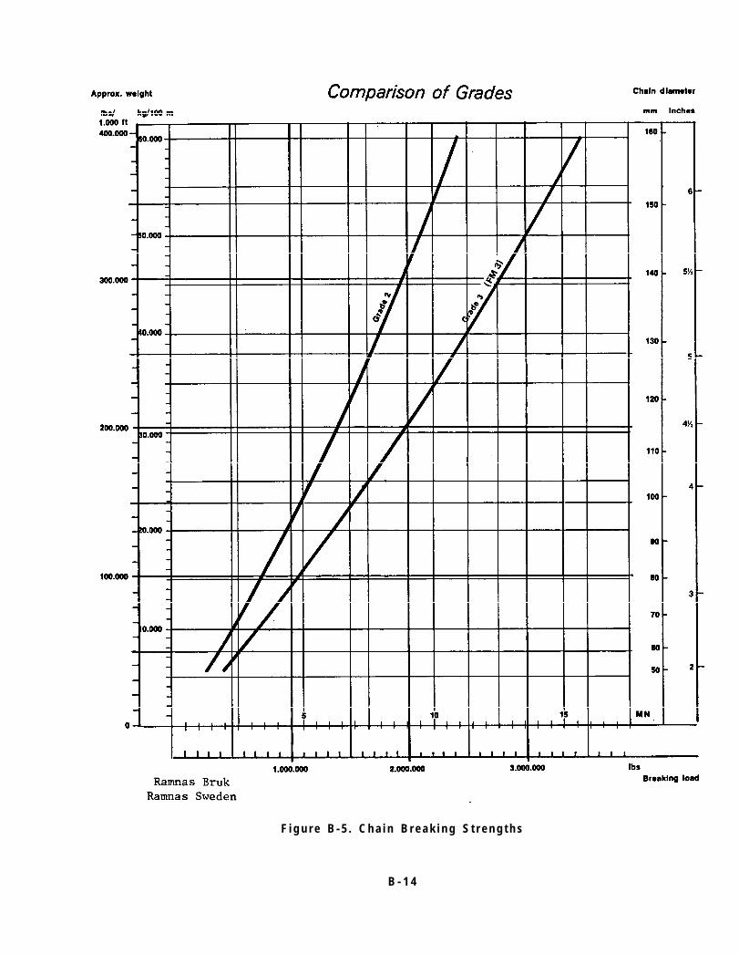
F i g u r e B - 5 . C h a i n B r e a k i n g S t r e n g t h s
B - 1 4

TYPICAL CHAIN JOINING LINK-BALDT(Al l D imens ions in Inches)
NominalD i a m e t e r A ( m i n ) A ( m a x ) B ( m i n ) B ( m a x ) C ( m i n ) C ( m a x ) D ( m i n ) D ( m a x )
1 1/4
1 3/4
2
2 1/4
2 1/2
2 3/4
3
3 1/2
4
7.31
10.24
11.70
13.16
14.63
16.09
17.55
20.60
23.40
7.69
10.76
12.30
13.84
15.38
16.91
18.45
21.65
24.60
4.88
7.31
7.56
8.50
9.45
10.54
11.33
13.44
15.11
5.13
7.69
7.94
8.94
9.93
11.08
11.92
14.13
15.89
1.69 1.78 1.22 1.23
2.38 2.50 1.71 1.79
2.44 2.56 1.95 2.05
2.74 2.88 2.19 2.31
3.05 3.20 2.44 2.56
3.60 3.78 2.80 2.95
3.66 3.84 2.93 3.08
4.69 4.93 3.66 3.84
5.06 5.32 3.90 4.10
TYPE
E(m in ) E (max ) F (m in ) F (max ) G (m in ) G (max )
1.37 1.44
1.95 2.05
2.25 2.37
2.56 2.69
2.80 2.95
3.17 3.33
3.44 3.62
4.02 4.23
4.51 4.74
1.49 1.57 0.79
2.16 2.27 1.16
2.44 2.56 1.28
2.74 2.88 1.46
3.05 3.20 1.61
3.60 3.78 1.77
3.66 3.84 1.92
4.39 4.61 2.35
4.81 5.06 2.62
0.63
1.22
1.35
1.54
1.70
1.86
2.02
2.47
2.75
NOTE :
ALL CHAIN JOINING LINKS MUSTBE COMPATIBLE WITH THECOMMON STUD LINK OF THE SAMENOMINAL SIZE.
Figure B-6. Chain Joining Link- Baldt Type
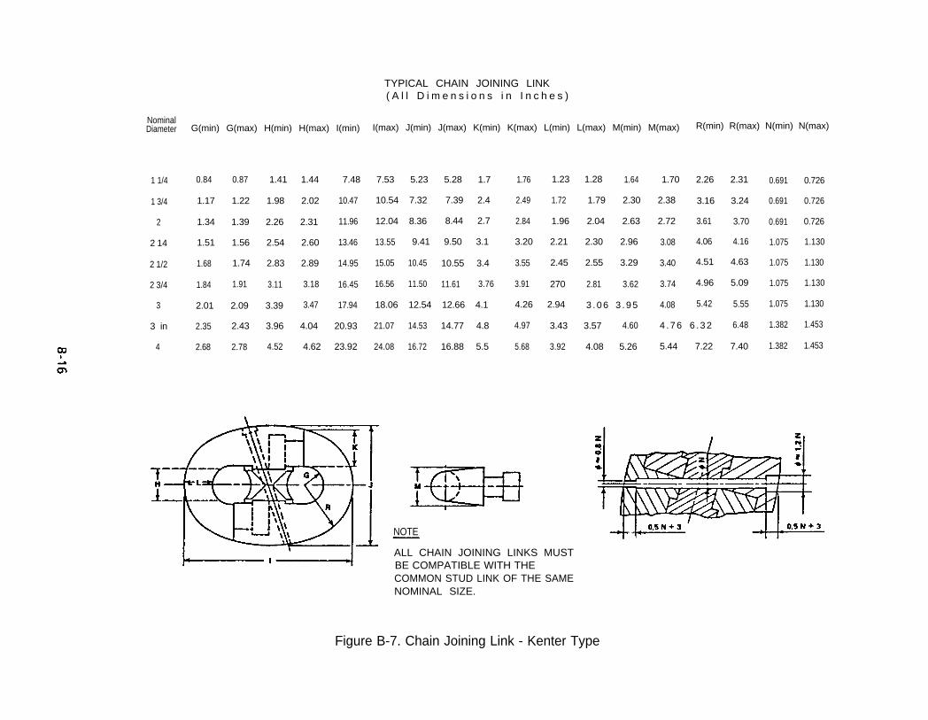
TYPICAL CHAIN JOINING LINK( A l l D i m e n s i o n s i n I n c h e s )
NominalDiameter G(min) G(max) H(min) H(max) I(min) I(max) J(min) J(max) K(min) K(max) L(min) L(max) M(min) M(max) R(min) R(max) N(min) N(max)
1 1/4 0.84 0.87 1.41 1.44 7.48 7.53 5.23 5.28 1.7 1.76 1.23 1.28 1.64 1.70 2.26 2.31 0.691 0.726
1 3/4 1.17 1.22 1.98 2.02 10.47 10.54 7.32 7.39 2.4 2.49 1.72 1.79 2.30 2.38 3.16 3.24 0.691 0.726
2 1.34 1.39 2.26 2.31 11.96 12.04 8.36 8.44 2.7 2.84 1.96 2.04 2.63 2.72 3.61 3.70 0.691 0.726
2 14 1.51 1.56 2.54 2.60 13.46 13.55 9.41 9.50 3.1 3.20 2.21 2.30 2.96 3.08 4.06 4.16 1.075 1.130
2 1/2 1.68 1.74 2.83 2.89 14.95 15.05 10.45 10.55 3.4 3.55 2.45 2.55 3.29 3.40 4.51 4.63 1.075 1.130
2 3/4 1.84 1.91 3.11 3.18 16.45 16.56 11.50 11.61 3.76 3.91 270 2.81 3.62 3.74 4.96 5.09 1.075 1.130
3 2.01 2.09 3.39 3.47 17.94 18.06 12.54 12.66 4.1 4.26 2.94 3 . 0 6 3 . 9 5 4.08 5.42 5.55 1.075 1.130
3 in 2.35 2.43 3.96 4.04 20.93 21.07 14.53 14.77 4.8 4.97 3.43 3.57 4.60 4 . 7 6 6 . 3 2 6.48 1.382 1.453
4 2.68 2.78 4.52 4.62 23.92 24.08 16.72 16.88 5.5 5.68 3.92 4.08 5.26 5.44 7.22 7.40 1.382 1.453
NOTE
ALL CHAIN JOINING LINKS MUSTBE COMPATIBLE WITH THECOMMON STUD LINK OF THE SAMENOMINAL SIZE.
Figure B-7. Chain Joining Link - Kenter Type

B-17

TYPICAL ANCHOR JOINING LINK - KENTER TYPE
NominalDiameter A(max) B(max) C(min) C(max) H(rnin) H(max) J(max) J(min) K(max)
1 1/4 1.88 1.56 0.751 3/4 2.63 2.19 1.052 3.00 2.50 1.20
2 1/4 3.38 2.81 1.352 1/2 3.75 3.13 1.502 3/4 4.13 3.44 1.55
3 4.50 3.75 1.803 1/2 5.25 4.38 2.10
4 6.00 5.00 2.40
(All Dimensions in Inch
1.001.401.601.802.002.202.402.803.20
1.472.062.362.652.953.243.544.134.72
1.502.102.402.703.003.303.604.205.00
2.062.893.303.714.134.544.955.786.50
1.251.752.002.252.502.753.003.504.00
1.562.192.502.813.133.443.754.385.00
-M(min) N(min) N(max) P(min) P(max)
1.502.102.402.703.003.303.604.204.80
1.502.192.502.813.133.443.754.385.00
1.752.452.803.153.503.854.204.905.60
2.122.983.403.834.254.685.105.956.80
2.753.854.404.955.506.056.607.708.80
Figure B-9. Anchor Joining Link - Kenter Type

TYPICAL JOINING SHACKLE DIMENSIONS(All Dimensions in Inches)
NominalDiameter
G(min)
1.58
2.22
2.54
G(max)
1.67
H(min)
4.14
H(max)
4.36
I(min)
4.88
6.83
7.80
8.78
9.75
10.73
11.70
13.65
15.60
I(min)
5.13
7.18
8.20
9.23
10.25
11.28
12.30
14.35
16.40
J(max)
2.05
Kapprox.
3.50
J(min)
1.951 1/4
2.87
3.28
3.69
5.80 6.10 2.73
3.12
3.51
1 3/4 2.33
2.67
4.90
2 6.63
7.46
6.97
7.84
8.71
5.60
6.30
7.00
7.70
8.40
3.002 1/4 2.85
3.17
3.49
3.90
4.29
4.10
4.51
2 1/2 3.33
3.66
8.29
9.12
9.95
2 3/4 9.58
10.46
12.20
13.94
4.924.00 4.683 3.80
5.74 9.80
11.20
4.66 11.60 5.46
6.24
3 1/2 4.44
13.26 6.564 5.07 5.33
ALL JOINING SHACKLES MUST FIT THE END LINK
Figure B-10. Joining Shackle
B-19

B-20
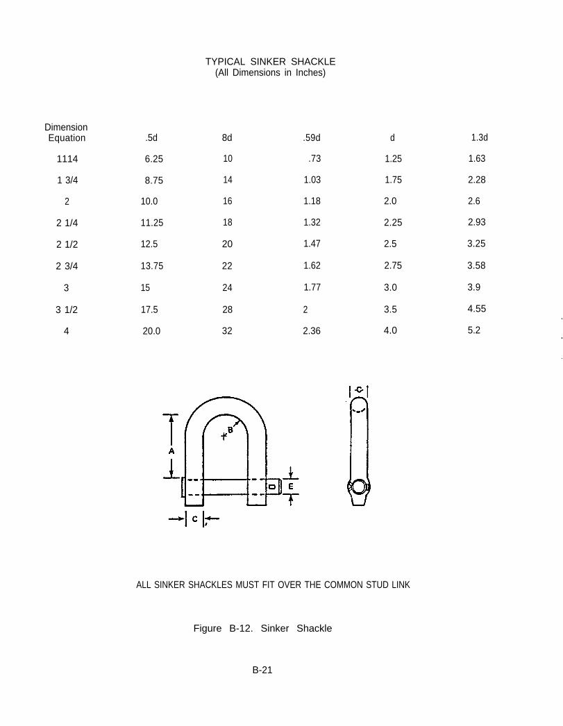
TYPICAL SINKER SHACKLE(All Dimensions in Inches)
DimensionEquation
1114
1 3/4
2
2 1/4
2 1/2
2 3/4
3
3 1/2
4
.5d
6.25
8.75
10.0
11.25
12.5
13.75
15
17.5
20.0
8d
10
14
16
18
20
22
24
28
32
.59d
.73
1.03
1.18
1.32
1.47
1.62
1.77
2
2.36
d
1.25
1.75
2.0
2.25
2.5
2.75
3.0
3.5
4.0
ALL SINKER SHACKLES MUST FIT OVER THE COMMON STUD LINK
Figure B-12. Sinker Shackle
B-21
1.3d
1.63
2.28
2.6
2.93
3.25
3.58
3.9
4.55
5.2

(All Dimensions in Inches)
Nominal A A C C E E F G H
Diameter (min) (max) B (min) (max) (min) (max) (min) (min) (max)
1 1/4 7.50 7 . 6 9 1 . 6 3 1 . 2 5 1.28 4.44 4.56 1.20 1.05 1.25
1 3/4 10 .50 10 .76 2 .28 1 .75 1.79 6.21 6.39 1.50 1.41 1.50
2 12 .00 12 .30 2 .60 2 .00 2.05 7 . 1 0 7 . 3 0 1.65 1.59 1.77
2 1/4 13 .50 13 .84 2 .93 2 .25 2.31 7 . 9 9 8 . 2 1 1.18 1.59 2.09
2 1/2 15 .00 15 .38 3 .25 2 .50 2.56 8.88 9.13 1.95 1.64 2.23
2 3/4 16 .50 16 .91 3 .58 2 .75 2 . 8 2 9 . 7 6 1 0 . 0 4 2.10 1.00 2.40
3 18 .00 18 .45 3 .90 3 .00 3 .08 10 .65 10 .95 2.25 1.94 2.62
3 1/2 21 .00 21 .53 4 .55 3 .50 3 .59 12 .43 12 .78 2.40 2.38 3.12
4 24 .00 24 .60 5 .20 4 .00 4.10, 14.20 14.60 2.70 2.58 3.58
Figure B-13. Common Stud Link Chain
B-22

ENLARGED LINK(All Dimensions in Inches)
NominalDiameter
DimensionEquation
1 1/4
1314
2
2 1/4
2 1/2
2314
3
3 1/2
4
A (min)
6.6d
8.25
11.55
13.2
14.85
16.5
18.15
19.8
23.1
26.4
A (max)
6.75d
8.44
11.81
13.5
15.2
16.88
18.56
20.25
23.63
27.0
B C (min)
1.43d 1.1d
1.78 1.37
2.50 1.93
2.86 2.20
3.20 2.47
3.58 2.75
3.90 3.03
4.30 3.30
5,0 3.85
5.72 4.40
C (max)
1.1ld+T
1.41
2.0
2.26
2.56
2.84
3.12
3.39
3,94
4.5
E (min)
3.91d
4.89
6.84
7.82
8.8
9.78
10.75
11.73
13.69
15.64
E(max)
4.01d
5.01
7.02
8.02
9.02
10.03
11.03
12.03
14.04
16.04
Figure B-14. Enlarged Link
B-23

END LINK(All Dimensions in Inches)
NominalDiameter
1 1/4
1 3/4
2
2 1/4
2 1/2
2 3/4
3
3 1/2
4
A (min) A (max) C (min) C (max) D (min) D (max)
8.44
11.81
13.50
15.19
16.88
18.56
20.25
23.65
27.0
8.63
12.08
13.80
15.53
17.25
18.98
20.70
24.15
27.60
1.50
2.10
2.40
2.70
3.00
3.30
3.60
4.20
4.80
1.53
2.16
2.49
2.79
3.1
3.4
3.69
4.29
4.89
4.94
6.91
7.90
8.89
9.88
10.86
11.85
13.83
15.80
5.06
7.09
8010
9.11
10.13
11.14
12.15
14.18
16.20
Figure B-15. End Link
B-24
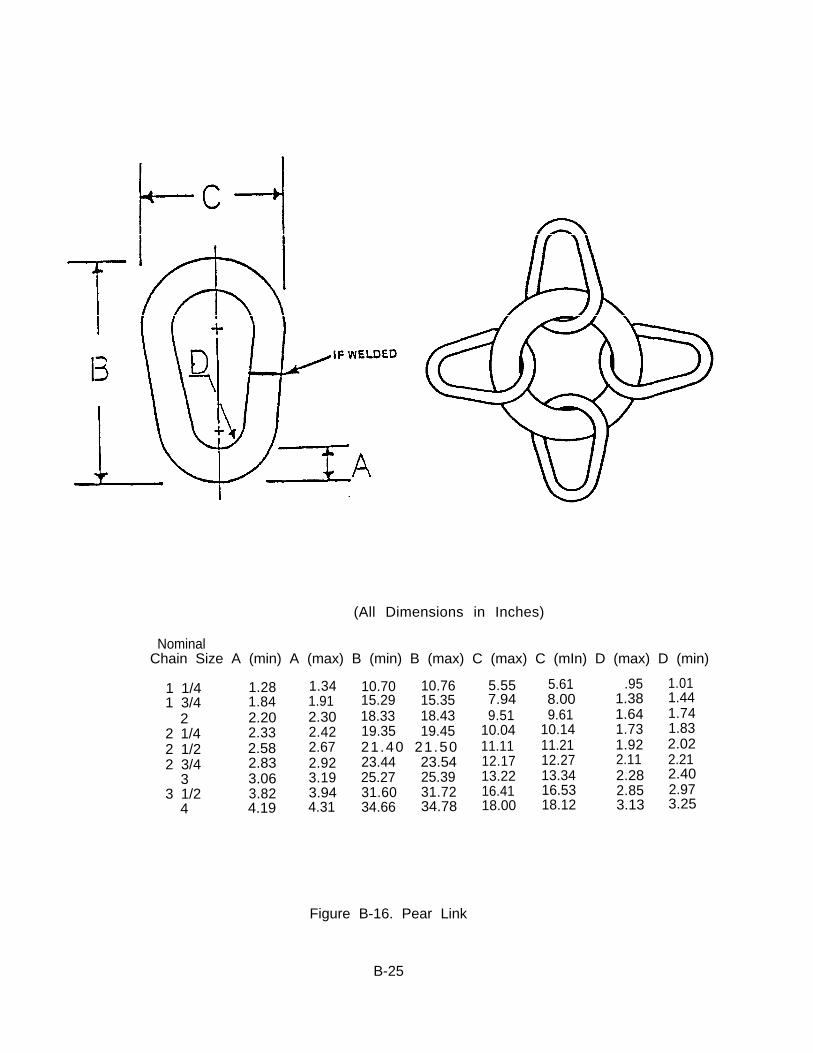
(All Dimensions in Inches)
NominalChain Size A (min) A (max) B (min) B (max) C (max) C (mIn) D (max) D (min)
1 1/41 3/4
22 1/42 1/22 3/4
33 1/2
4
1.28 1.34 10.70 10.76 5.55 5.61 .95 1.011.84 1.91 15.29 15.35 7.94 8.00 1.38 1.442.20 2.30 18.33 18.43 9.51 9.61 1.64 1.742.33 2.42 19.35 19.45 10.04 10.14 1.73 1.832.58 2.67 21.40 21.50 11.11 11.21 1.92 2.022.83 2.92 23.44 23.54 12.17 12.27 2.11 2.213.06 3.19 25.27 25.39 13.22 13.34 2.28 2.403.82 3.94 31.60 31.72 16.41 16.53 2.85 2.974.19 4.31 34.66 34.78 18.00 18.12 3.13 3.25
Figure B-16. Pear Link
B-25

TYPICAL SWIVEL(All Dimensions in Inches)
A A B B C C D D E ENominal
Chain Size
1 1/41 3/4
22 1/42 1/22 3/43 1/2
(min)
12.1917.0621.0321.9425.9126.8134.13
(max)
12.8117.9422.1123.0627.2328.1935.88
(min)
5.728.01
10.3110.3112.6012.6016.04
(max)
6.028.43
10.8310.8313.2413.2416.86
(min)
4.396.147.027.908.789.65
12.29
(max)
4.616.467.388.309.23
10.1512.92
(min)
1.462.052.632.633.223.224.10
(max)
1.542.152.772.773.383.384.31
(min) (max)
1.221.711.952.192.442.683.41
1.281.792.052.312.562.823.59
Nominal F F G G H H J J K KChain Size (min) (max) (min) (max) (min) (max) (min) (max) (min) (max)
1 1/4 4.63 4.87 2.29 2.41 2.17 2.29 2.29 2.41 1.95 2.051 3/4 6.48 6.82 3.25 3.41 3.07 3.23 3.25 3.41 2.73 2.87
2 8.34 8.76 4.15 4.37 3.94 4.14 3.71 3.91 3.12 3.282 1/4 8.34 8.76 4.15 4.37 3.94 4.14 4.15 4.37 3.51 3.692 1/2 10.19 10.71 5.07 5.33 4.81 5.05 4.63 4.87 3.90 4.102 3/4 10.19 10.71 5.07 5.33 4.81 5.05 5.07 5.33 4.29 4.513 1/2 12.97 13.63 6.50 6.84 6.14 6.46 6.50 6.84 5.46 5.74
NOTE: SWIVELS SHALL BE PROVIDED WITH TWO COMMON LINKS OF THESPECIFIED NOMINAL CHAIN SIZE, ATTACHED AS SHOWN.
Figure B-17. Swivel
B-26
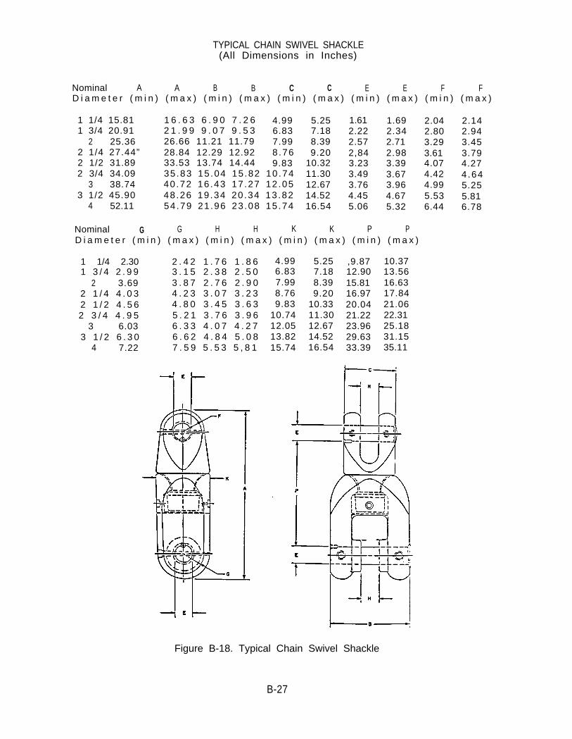
TYPICAL CHAIN SWIVEL SHACKLE(All Dimensions in Inches)
Nominal A A B B C C E E F FD i a m e t e r ( m i n ) ( m a x ) ( m i n ) ( m a x ) ( m i n ) ( m a x ) ( m i n ) ( m a x ) ( m i n ) ( m a x )
1 1/4 15.81 1 6 . 6 3 6 . 9 0 7 . 2 6 4.991 3/4 20.91 2 1 . 9 9 9 . 0 7 9 . 5 3 6.83
2 25.36 26.66 11.21 11.79 7.992 1/4 27.44” 28.84 12.29 12.92 8.762 1/2 31.89 33.53 13.74 14.44 9.832 3/4 34.09 35 .83 15 .04 15 .82 10 .74
3 38.74 40 .72 16 .43 17 .27 12 .053 1/2 45.90 48 .26 19 .34 20 .34 13 .82
4 52.11 54 .79 21 .96 23 .08 15 .74
5.257.188.399.20
10.3211.3012.6714.5216.54
1.61 1.69 2.042.22 2.34 2.802.57 2.71 3.292,84 2.98 3.613.23 3.39 4.073.49 3.67 4.423.76 3.96 4.994.45 4.67 5.535.06 5.32 6.44
Nominal G G H H K K P PD i a m e t e r ( m i n ) ( m a x ) ( m i n ) ( m a x ) ( m i n ) ( m a x ) ( m i n ) ( m a x )
1 1/4 2.301 3 / 4 2 . 9 9
2 3.692 1 / 4 4 . 0 32 1 / 2 4 . 5 62 3 / 4 4 . 9 5
3 6.033 1 / 2 6 . 3 0
4 7.22
2 . 4 2 1 . 7 6 1 . 8 63 . 1 5 2 . 3 8 2 . 5 03 . 8 7 2 . 7 6 2 . 9 04 . 2 3 3 . 0 7 3 . 2 34 . 8 0 3 . 4 5 3 . 6 35 . 2 1 3 . 7 6 3 . 9 66 . 3 3 4 . 0 7 4 . 2 76 . 6 2 4 . 8 4 5 . 0 87 . 5 9 5 . 5 3 5 , 8 1
4.996.837.998.769.83
10.7412.0513.8215.74
5.257.188.399.20
10.3311.3012.6714.5216.54
,9.8712.9015.8116.9720.0421.2223.9629.6333.39
10.3713.5616.6317.8421.0622.3125.1831.1535.11
2.142.943.453.794.274.645.255.816.78
Figure B-18. Typical Chain Swivel Shackle
B-27

TYPICAL RISER SWIVEL SHACKLE(A l l D imens ions in Inches)
NominalChain Size
1 1 /41 3 / 4
22 1 / 42 1 / 22 3 / 4
A A B C C G(min)1.612 .222.572.843.233.23
(max)1.692 .342.712.983.393.39
( m i n ) ( m i n )5 .62 3 .195.62 3.195.62 3.195.62 3.195.62 3.195.62 3.19
(max)3 .503 . 5 03 . 5 03.503 . 5 03 . 5 0
(max)5 .255 .255.255.255.255.25
NOTE : THE TOP END OF A RISER SWIVEL SHACKLE IS REQUIRED TO FIT A SHACKLE EYEPLATE OF A FLEET MOORING BUOY. THE BOTTOM END OF THE RISER SWIVELSHACKLE WILL BE THE SAME SIZE AS THE CHAIN SWIVEL SHACKLE AND WILL BEREQUIRED TO FIT A COMMON LINK OF THE SPECIFIED NOMINAL CHAIN SIZE, BUTTHE COMMON LINK SHALL NOT BE PROVIDED WITH THE RISER SWIVEL SHACKLE.RISER SWIVEL SHACKLES SHALL MEET ALL CHEMICAL, MECHANICAL, PHYSICAL ANDTESTING REQUIREMENTS SPECIFIED FOR THE SWIVEL OF THE SAME NOMINAL CHAINSIZE.
Figure B-19. Typical Riser Swivel Shackle
B-28

TYPICAL GROUND RING(All Dimensions in Inches)
NOTE:
NominalChain Size
1 1 /41 3 /4
22 1 /42 1 /22 3 /4
33 1 /2
4
A (min)
1.201.842.022.332.582.833.063.814.18
A (max)
1.341.912.302.422.672.923.193.944.31
B (min)
4.346.21
7.027.868.699.53
10.3412.8414.09
B (max)
4 .406.217.137.968.799.62
10.4712.9614.21
GROUND RINGS SHALL F IT THE LARGE END OF AN ANCHORJ O I N I N G L I N K O F T H E S A M E N O M I N A L C H A I N S I Z E A S T H EGROUND RING.
Figure B-20. Ground Ring
B-29

(All Dimensions in Inches)
Figure B-21. Spider Plate
B-30

Figure B-22. Chain Equalizer and lts Use
B-31
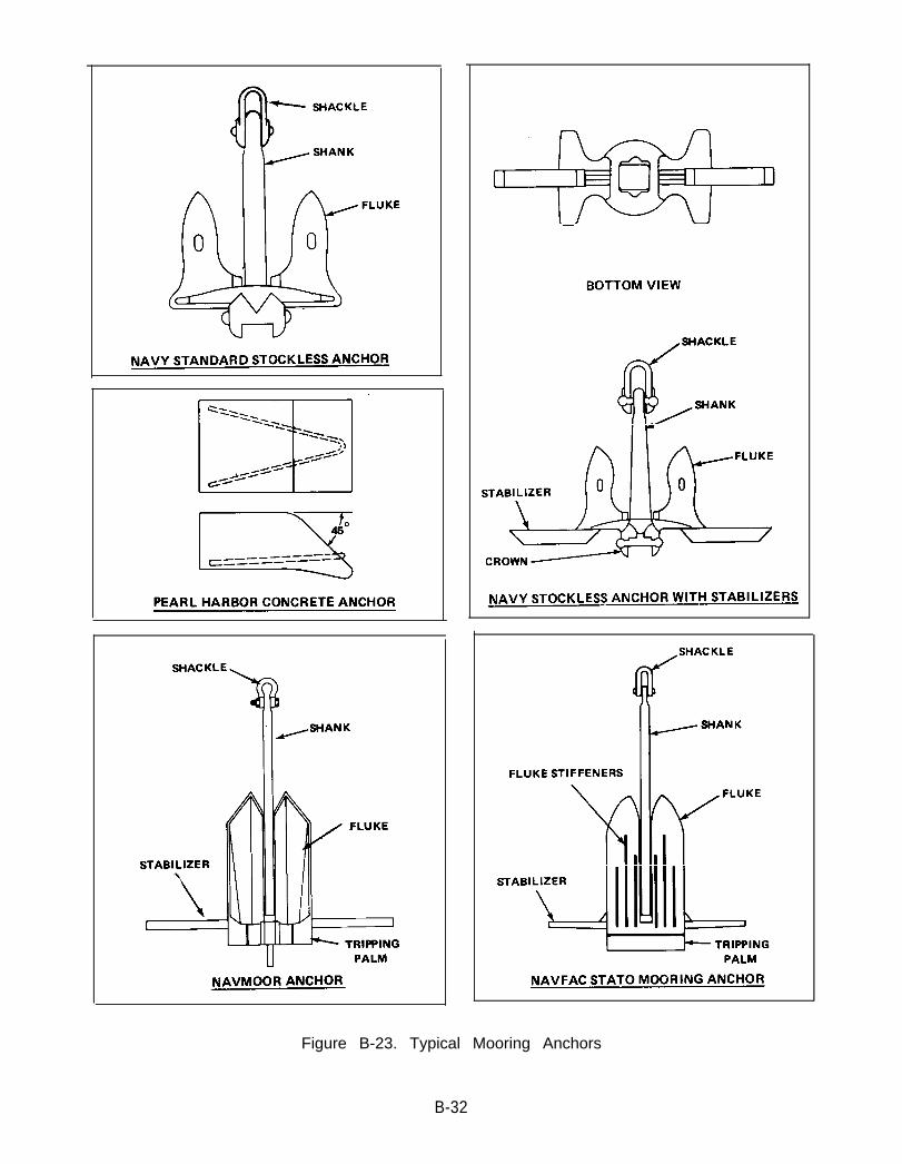
Figure B-23. Typical Mooring Anchors
B-32
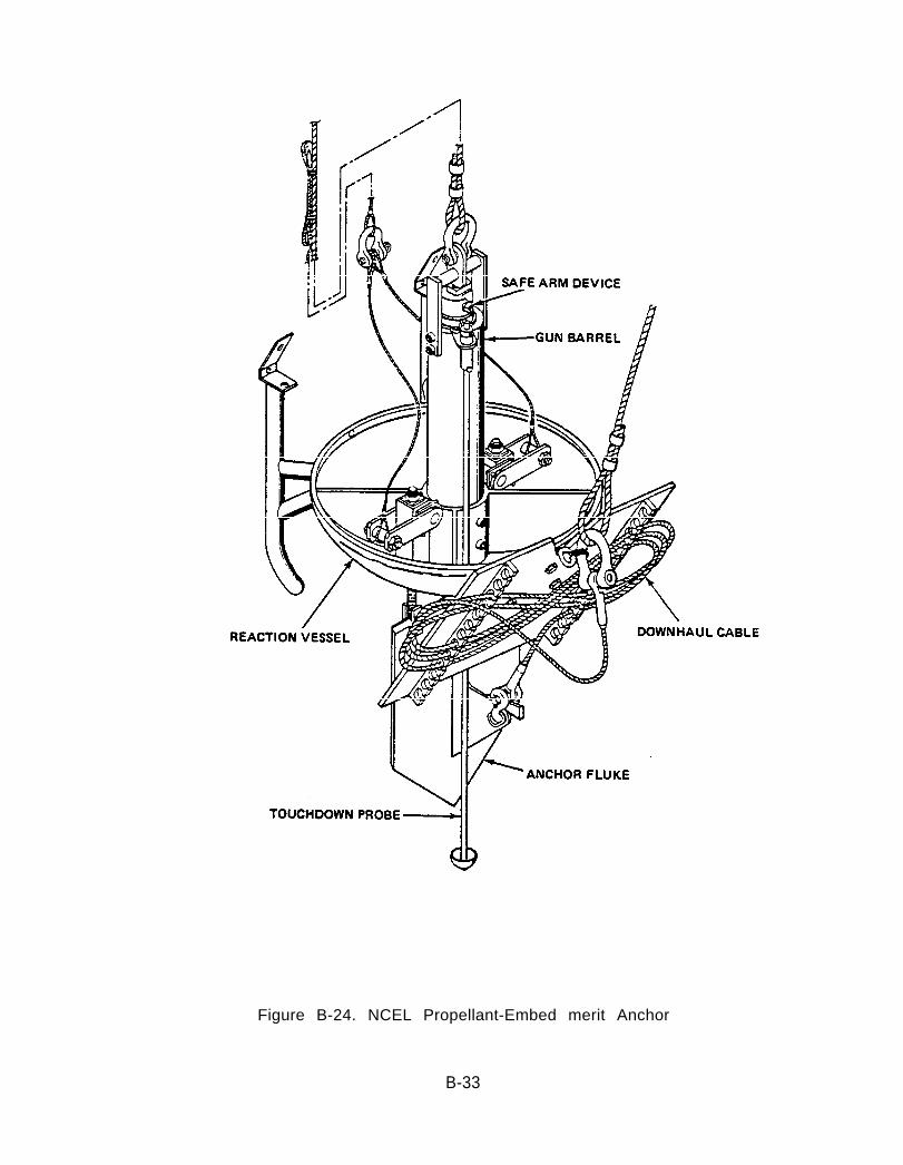
Figure B-24. NCEL Propellant-Embed merit Anchor
B-33
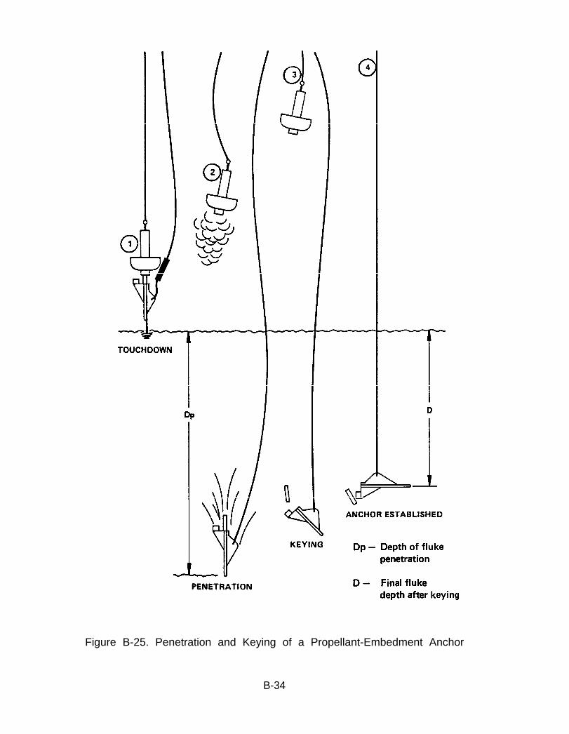
Figure B-25. Penetration and Keying of a Propellant-Embedment Anchor
B-34
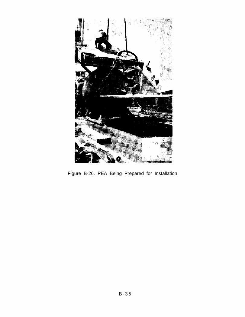
Figure B-26. PEA Being Prepared for Installation
B - 3 5

APPENDIX C
GLOSSARY
C-1
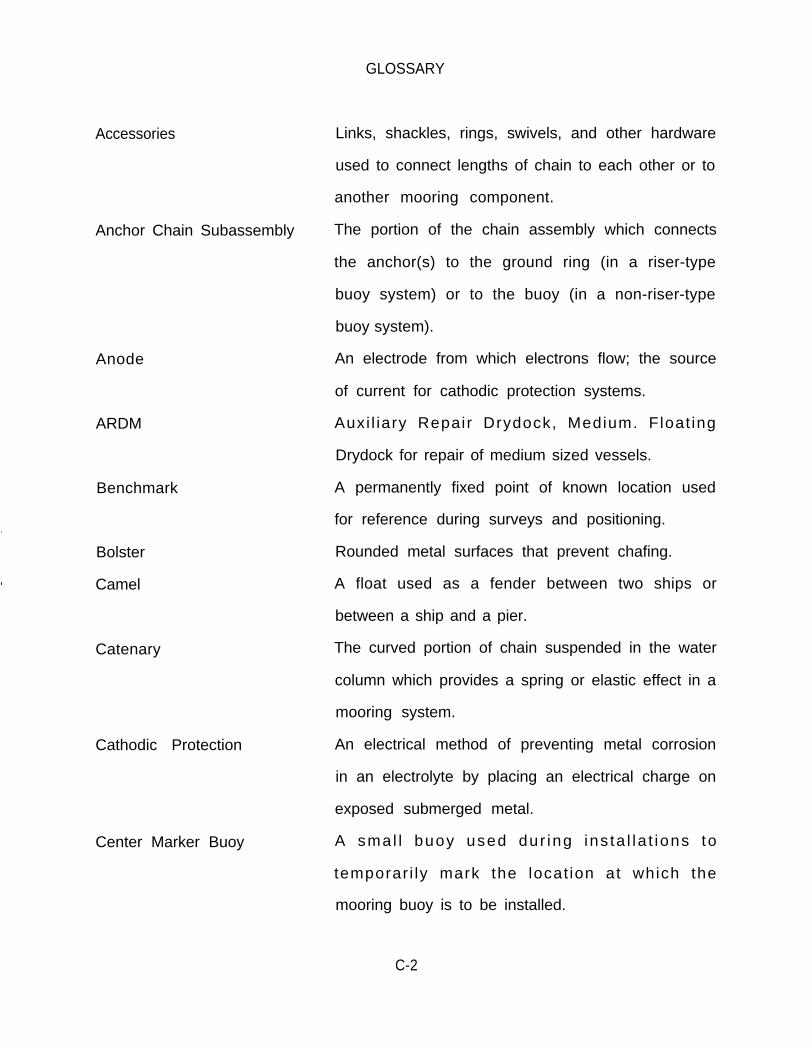
GLOSSARY
Accessories
Anode
ARDM
Benchmark
Bolster
Camel
Catenary
Cathodic Protection
Center Marker Buoy
Links, shackles, rings, swivels, and other hardware
used to connect lengths of chain to each other or to
another mooring component.
Anchor Chain Subassembly The portion of the chain assembly which connects
the anchor(s) to the ground ring (in a riser-type
buoy system) or to the buoy (in a non-riser-type
buoy system).
An electrode from which electrons flow; the source
of current for cathodic protection systems.
Auxi l iary Repair Drydock, Medium. Float ing
Drydock for repair of medium sized vessels.
A permanently fixed point of known location used
for reference during surveys and positioning.
Rounded metal surfaces that prevent chafing.
A float used as a fender between two ships or
between a ship and a pier.
The curved portion of chain suspended in the water
column which provides a spring or elastic effect in a
mooring system.
An electrical method of preventing metal corrosion
in an electrolyte by placing an electrical charge on
exposed submerged metal.
A sma l l buoy used dur ing ins ta l la t ions to
temporar i ly mark the locat ion at which the
mooring buoy is to be installed.
C-2
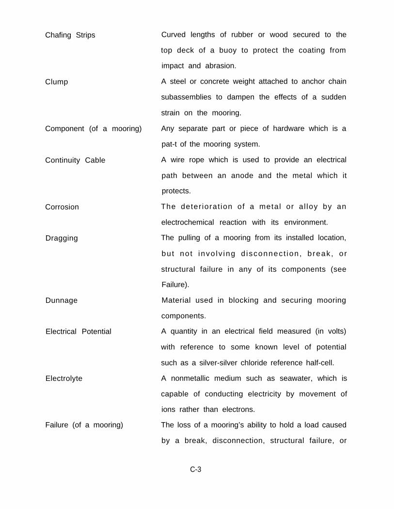
Chafing Strips
Clump
Corrosion
Dragging
Dunnage
Electrical Potential
Electrolyte
Failure (of a mooring)
Curved lengths of rubber or wood secured to the
top deck of a buoy to protect the coating from
impact and abrasion.
A steel or concrete weight attached to anchor chain
subassemblies to dampen the effects of a sudden
strain on the mooring.
Component (of a mooring) Any separate part or piece of hardware which is a
pat-t of the mooring system.
Continuity Cable A wire rope which is used to provide an electrical
path between an anode and the metal which it
protects.
The deter iorat ion of a metal or a l loy by an
electrochemical reaction with its environment.
The pulling of a mooring from its installed location,
bu t no t invo lv ing d isconnec t ion , b reak , o r
structural failure in any of its components (see
Failure).
Material used in blocking and securing mooring
components.
A quantity in an electrical field measured (in volts)
with reference to some known level of potential
such as a silver-silver chloride reference half-cell.
A nonmetallic medium such as seawater, which is
capable of conducting electricity by movement of
ions rather than electrons.
The loss of a mooring’s ability to hold a load caused
by a break, disconnection, structural failure, or
C-3

Fenders
Fit Check
Fittings
Fix
Fixed Moorings
Fleet Mooring Inventory
(FMI)
Fluke
Fluke Angle
Foul
Fouling
other f law in one or more o f the moor ing
components (see Dragging).
Curved lengths of rubber or wood secured to the
side plates of a buoy hull to protect the buoy from
impact and abrasion.
Temporary physical assembly of a mooring’s
components to ensure that the components will fit
together as called for in the mooring design.
See Accessories.
The determination of the geographic position of an
object in the water by means of angles, bearings,
distances, etc.
A mooring which consists of platforms, cells,
islands, dolphins, or similar structural systems
permanently fixed in a position to which a ship is
secured.
All mooring assemblies, subassemblies, and
components in use in the water or stored ashore.
The broad arms or palms of an anchor which
provide the load-holding capability when buried.
The measured angle between the flukes and the
shank of an anchor.
To entangle, obstruct, or jam. Not clear for
running.
An accumulation of deposits and marine growth on
materials and structures immersed in seawater for
extended periods of time.
C-4
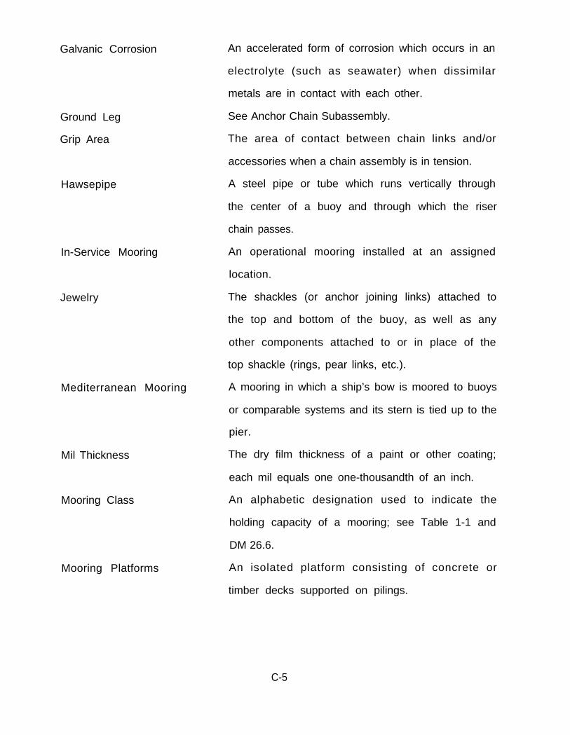
Galvanic Corrosion
Ground Leg
Grip Area
Hawsepipe
In-Service Mooring
Jewelry
Mil Thickness
Mooring Class
Mooring Platforms
An accelerated form of corrosion which occurs in an
electrolyte (such as seawater) when dissimilar
metals are in contact with each other.
See Anchor Chain Subassembly.
The area of contact between chain links and/or
accessories when a chain assembly is in tension.
A steel pipe or tube which runs vertically through
the center of a buoy and through which the riser
chain passes.
An operational mooring installed at an assigned
location.
The shackles (or anchor joining links) attached to
the top and bottom of the buoy, as well as any
other components attached to or in place of the
top shackle (rings, pear links, etc.).
Mediterranean Mooring A mooring in which a ship’s bow is moored to buoys
or comparable systems and its stern is tied up to the
pier.
The dry film thickness of a paint or other coating;
each mil equals one one-thousandth of an inch.
An alphabetic designation used to indicate the
holding capacity of a mooring; see Table 1-1 and
DM 26.6.
An isolated platform consisting of concrete or
timber decks supported on pilings.
C-5

New Installation
(of a mooring)
Out-of-Service
Overhaul
Pelican Hook
Pendant
Pickup Buoy
Pitting Corrosion
Range
Range Buoys
Recovery (of a mooring)
Refurbishment
The placement of a mooring at a new location
usually involving the assignment of a new mooring
number.
An installed mooring which is unoperational
(because of damage or deterioration, etc.) or a
mooring or mooring components which are
temporarily stored ashore.
The complete recovery,
reinstallation of an existing
re fu rb ishment , and
mooring.
A hinged hook fitted with a sliding or hinged link
held closed by a ring which is used to provide
instantaneous release of chain, anchors, wire rope,
etc.
A length of line or wire rope fitted with an eye or
block atone or both ends.
A small buoy used to facilitate retrieval of sunken
objects (see Retriever Buoy).
A highly localized and self-accelerating form of
corrosion that generally occurs on the surface of
metals immersed in seawater.
To lay out a length of chain in a straight line.
Small buoys temporarily installed along a line of
bearing to assist in movement and orientation of a
crane barge during mooring installations.
The complete retrieval of all mooring components.
T h e c l e a n i n g , i n s p e c t i o n , r e p a i r , a n d
reconditioning of mooring components ashore.
C-6

Repair (of a mooring)
Retriever Buoy
Ring Marker Buoy
Riser Subassembly
Rust Bleeding
Sacrificial Anode
Shot
Sinker
Splash Zone
The correction or remedy of a defective condition
while a mooring is in service.
A relatively small buoy attached by a wire rope to
an anchor or an anchor chain subassembly. This
buoy marks the position of the mooring material to
which it is attached and precludes a search for this
material during recovery operations.
Used to denote the position at which a mooring
anchor is to be installed. It also marks the direction
of an anchor chain subassembly from the desired
position of the mooring buoy.
Vertical chain extending from a ground ring
upward to a mooring buoy; includes the ground
ring and attached joining links.
A rust-colored discoloration of surrounding coating
caused by localized corrosion of exposed metal.
A metallic anode (usually zinc) which supplies
electrons for cathodic protection of another metal,
thereby consuming or “sacrificing” itself.
A 15-fathom (90-foot) length of chain.
See Clump.
The region immediately above the high tide level;
the splashing action of waves keeps this area
continually wetted by highly oxygenated seawater;
materials suffer accelerated rates of corrosion in
this zone.
C-7

Spud Mooring
Stake Piles
Stud
Taut
Tension Bar
Toggle Bar
Tripping Palms
Upgraded Mooring
Watch Circle
Wear Zone
A mooring which is used to secure a floating dock
to a pier or series of mooring platforms. The spuds
are usually H shaped steel sections fastened
vertically to the side of the pier at two or more
locations.
Steel or wood piling anchors driven vertically into a
firm bottom.
The center cross bar in steel chain link.
The condition of a chain, l ine, wire rope, or
mooring when under sufficient tension to cause it
to assume a straight line.
A heavy steel load carrying member which runs
vertically through the center of a buoy and to
which the riser chain is attached at the bottom and
mooring lines are attached at the top.
Bar or pin fitted into an eye or ring; used to permit
a quick release.
Projections from an anchor that trips the flukes at
an angle for embedding.
A mooring which consists of FM 3 fleet mooring
chain, a cathodic protection system, high capacity
anchors, and a urethane-coated foam filled buoy.
The area swept by a vessel as it revolves about a
mooring point.
The portion of the chain assembly near the bottom
which experiences the highest rate of wear due to
abrasion of seafloor material.
C-8

Weather Vane
Wire Diameter
A vessel free swinging around a mooring buoy to
assume an orientation which presents the least
resistance to the combined effect of wind and
current.
The diameter of the bar stock from which chain and
accessories are manufactured; also, the nominal
size of chain and accessories as measured across the
smallest diameter of the load bearing structure.
C-9
APPENDIX D
KENTER JOINING LINK ASSEMBLY
D-1

KENTER JOINING LINK
Kenter Joining Link. The Kenter-type joining link is of alloy steel and constructed in
three parts, one of which is the stud. The two main parts and stud have matching
numbers and arrow on the stud which is lined up with an arrow on the main part for
ease of assembly (See Figure D-l). The two main parts are attached to the ends of
the chain in the vertical position and then fitted together, the stud slides in place
and locks the whole link. The stud is secured by hammering a tapered pin into the
hole drilled diagonally through all three parts of the joining link. This hole is
tapered, and when the pin is driven home, a small conical recess, called the
“Dovetail Chamber” is left clear above its head. A lead pellet is hammered broad
end first into this chamber so as to fill it completely and thereby keep the pin in
place. During the final stage of hammering the lead pellet into the Dovetail
Chamber, precaution must be taken to prevent flat, small pieces of lead from flying
off the joining link into the face or eyes. The assembly procedure is depicted on the
last two pages of this appendix.
Prior to assembly, the internal mating surfaces of a Kenter joining link should
be coated with a molybdenum disulphide grease (MIL-G-23549) or an equivalent
lithium based grease. When assembling and before inserting a lead pellet, any
remaining lead in the Dovetail Chamber must be reamed out with a reamer tool
Failure to do this could result in the new lead pellet working out. After assembly
the link is painted with anchor chain paint, MI L-P-24380 (NSN 8010-00-145-0332 an
NSN 8010-00-145-0341 for 1 and 5 gallon cans respectively).
D-2

When disassembling a Kenter joining link, the locking pin is driven out with a
“drift.” To part the link, a top swage must always be used between the hammer
and link. The swage is shaped to the curvature of the link so that machined surfaces
are not damaged (See Figure D-2).
Figure D-1. A Kenter Joining Link
Figure D-2. A Top Swage and Reamer
D-3
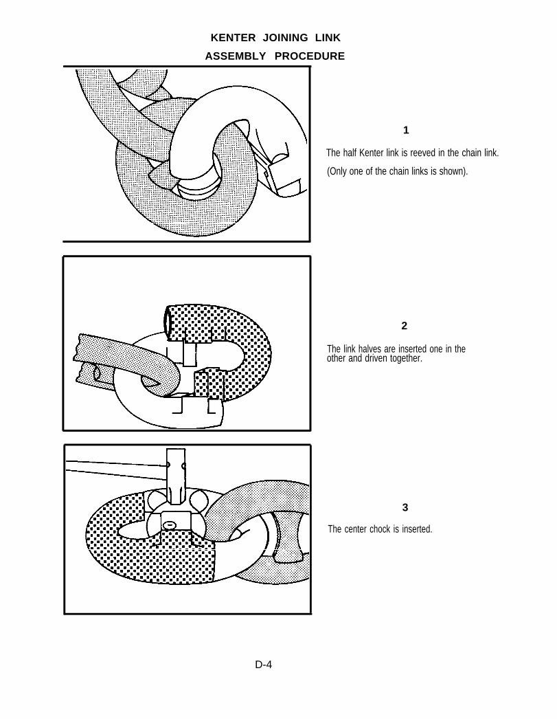
KENTER JOINING LINK
ASSEMBLY PROCEDURE
1
The half Kenter link is reeved in the chain link.
(Only one of the chain links is shown).
2
The link halves are inserted one in theother and driven together.
3
The center chock is inserted.
D-4
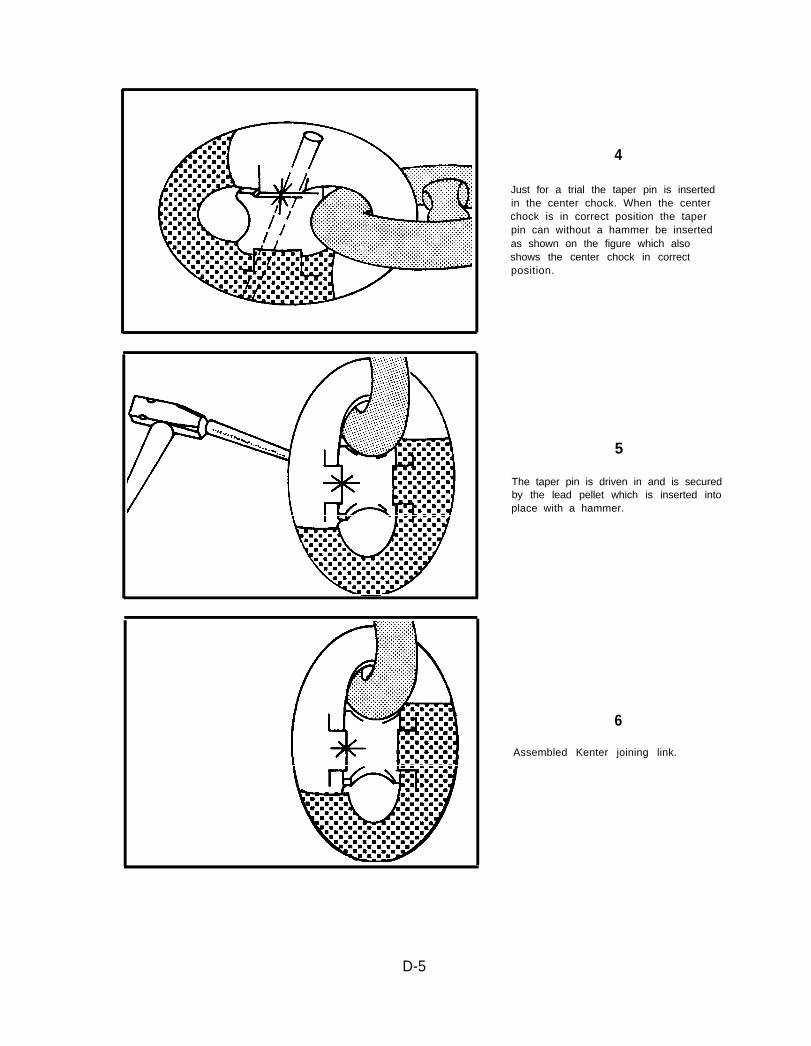
4
Just for a trial the taper pin is insertedin the center chock. When the centerchock is in correct position the taperpin can without a hammer be insertedas shown on the figure which alsoshows the center chock in correctposition.
5
The taper pin is driven in and is securedby the lead pellet which is inserted intoplace with a hammer.
6
Assembled Kenter joining link.
D-5

APPENDIX E
ANCHOR PULL TEST REQUIREMENTS
E-1

APPENDIX E
ANCHOR PULL TEST REQUIREMENTS
1.0 GENERAL. This appendix establishes the procedures for setting and pull
testing of anchor legs. Tables of predicted anchor system drag distance are included
to assist in initial anchor positioning.
1.2 SETTING DRAG ANCHORS. Proof setting of each anchor leg should be
accomplished using harbor tugs, Fleet tugs or by pulling diametrically opposite
anchor legs against each other. When setting the anchor, it is desirable to have a 10
to 1 scope (see Figure E-1 for definition) in the mooring line. This may be
accomplished by adding chain or a work wire. The anchor drag distance to achieve
the specified load level must be known to enable proper anchor placement prior to
proof loading. Setting shall be accomplished by pulling to the design load of the
mooring.
Scope is the ratio of length of rode (L) to depth of water (D), plus allowance for heigth of bow above water. At (1)length of rode equals the depth. At (2) rode length is twice the depth, at (4) four times the depth. Note how the angle be-tween rode and bottom decreases. At (B) the scope is 8:1 and the short length of chain at the anchor lies flat on the bottom.
Figure E-1. Mooring Leg Scope
1.2.1 DRAG DISTANCE
● Single Anchors. The predicted anchor drag distance for single anchors
can be obtained from Table E-1.
E-2

● Tandem Anchor Systems. The predicted anchor drag distance for tandem
anchor systems can be obtained from Table E-2.
1.2.2 LOAD MEASUREMENT. While setting the anchor, it is desirable to monitor the
loads. A currently calibrated dynamometer should be placed in line to measure the
load.
1.2.3 FINAL ANCHOR POSITION. It is expected that the desired holding capacity can
be achieved during setting and that the anchor will be within the 40’ long by 20’
wide allowable anchor area (see Figure E-2). If after setting, the desired load is not
obtained, or if the anchor drags outside the tolerance box, then the anchor must be
repositioned and the pull test repeated.
1.3 PULL TESTING. After the anchor is set, the pull test should be conducted. It is
important that a length of chain equal to the total length of riser and ground leg be
used for the test. Use of shorter chain lengths will create an uplift force on the
anchor.
1.3.1 LOADING PROCEDURE. Each anchor leg should be pull tested independently.
The vessel performing the pull should gradually build up to the proof test load.
Increase the load in 10,000 pound increments up to the required proof test load.
After each 10,000 pound increase allow the dynamometer reading to stabilize.
Once the required pull test load is reached, allow the dynamometer reading to
stabilize, then hold the pull test load for 3 minutes.
1.3.2.1 Anchor Leg Adequate. If the desired load is obtained and the anchor is
positioned within the tolerance box, the anchor leg is adequate.
1.3.2.2 Anchor Leg Inadequate. If either the pull test load is not achieved or the
anchor is out of position, the anchor must be repositioned and the pull
test repeated.
E-3

E-4

1.3.2.3 Pull test not achieved. If the pull test load cannot be achieved, the
anchor system design may not be correct. Several options exist for
increasing the anchors capacity:
● Changing the anchor fluke angle. Usually the fluke is fixed fully
open for muds and partially open (approximately 35°) for sands.
● Soaking. When deploying anchors in silt or clay (muds) it is
desirable to allow the anchors to soak. “Soaking” of an anchor is
the practice of allowing a newly embedded anchor to rest for a
period of time, typically 24 hours, before applying the required
proof load.
● Jetting. If a drag anchor does not bury to a sufficient depth to
develop the required capacity, it maybe possible to use divers to jet
the anchor to the required depth. The anchor should be jetted to a
depth equal to or greater than the length of the anchor fluke.
1.3.2.4 Anchor out of position. If the anchor is not within the tolerance box,
reposition the anchor accordingly, reset and repeat the pull test. *
* Note: Ensure that the anchor is not recovered and reset in the furrow or
disturbed bottom area caused by the initial pull test.
E-5

PREDICTED SINGLE ANCHOR DRAG DISTANCES
TABLE E-1
Anchor: Stockless Anchor with Stabilizers and Flukes Fixed at approximately450
Seafloor Type: Mud
Horizontal Design Load (Kips)
25. 50. 75. 100. 125. 150. 175. 200. 225. 250. 275. 300.AnchorWeight(Kips)
6.7.8.9.
10.11.12.13.14.15.16.17.18.19.20.21.22.23.24.25.26.27.28.2930.
54. *32.21.13.9.66.6.5.5.5.4.4.4.3.3.2.2.2.1.1.1.1.1.0.
****
183.99.64.47.40.33.27.22.17.14.12.10.8.8.8.8.7.7.7.7.
************
154.95.77.64.53.48.42.37.33.29.25.21.19.
******************
202.152.104.89.78.68.59.
************************
************************
245. *
*************************
Drag Distance
*************************
(Feet )
*************************
*************************
*************************
*************************
*Exceeds anchor ultimate holding capacity
E-6
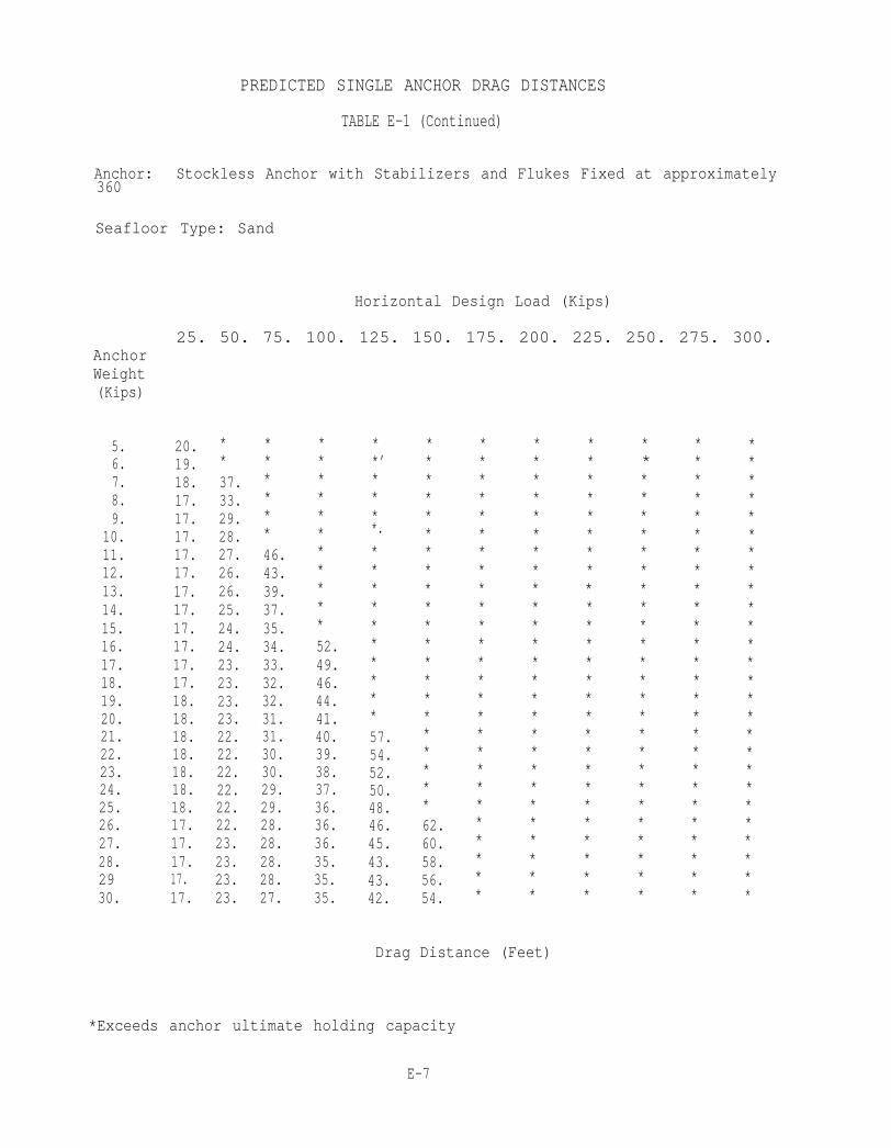
PREDICTED SINGLE ANCHOR DRAG DISTANCES
TABLE E-1 (Continued)
Anchor: Stockless Anchor with Stabilizers and Flukes Fixed at approximately360
Seafloor Type: Sand
Horizontal Design Load (Kips)
25. 50. 75. 100. 125. 150. 175. 200. 225. 250. 275. 300.AnchorWeight(Kips)
5.6.7.8.9.
10.11.12.13.14.15.16.17.18.19.20.21.22.23.24.25.26.27.28.2930.
20.19.18.17.17.17.17.17.17.17.17.17.17.17.18.18.18.18.18.18.18.17.17.17.17.17.
**37.33.29.28.27.26.26.25.24.24.23.23.23.23.22.22.22.22.22.22.23.23.23.23.
******46.43.39.37.35.34.33.32.32.31.31.30.30.29.29.28.28.28.28.27.
***********52.49.46.44.41.40.39.38.37.36.36.36.35.35.35.
**’****.
**********57.54.52.50.48.46.45.43.43.42.
*********************62.60.58.56.54.
**************************
**************************
Drag Distance (Feet)
**************************
* ** *************************
************************
**************************
*Exceeds anchor ultimate holding capacity
E-7
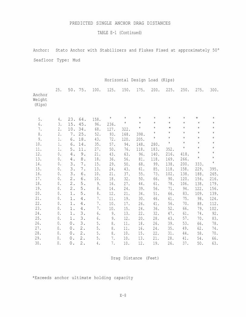
PREDICTED SINGLE ANCHOR DRAG DISTANCES
TABLE E-1 (Continued)
Anchor: Stato Anchor with Stabilizers and Flukes Fixed at approximately 50°
Seafloor Type: Mud
Horizontal Design Load (Kips)
AnchorWeight(Kips)
5.6.7.8.9.
10.11.12.13.14.15.16.17.18.19.20.21.22.23.24.25.26.27.28.29.30.
25.
4.3.2.2.1.1.1.0.0.0.0.0.0.0.0.0.0.0.0.0.0.0.0.0.0.0.
50. 75.
23. 64.15. 45.10. 34.7. 25.6. 18.6. 14.5. 11.4. 9.4. 8.3. 7.3. 7.3. 6.2. 6.2. 5.2. 5.1. 5.1. 4.1. 4.1. 4.1. 3.1. 3.0. 3.0. 2.0. 2.0. 2.0. 2.
100.
158.96.68.52.43.35.27.21.18.15.13.10.10.9.8.8.7.7.7.6.6.5.5.5.5.4.
125.
*236.127.93.72.57.50.43.36.29.24.21.18.16.14.12.11.10.10.9.9.8.8.8.7.7.
150.
**
322.168.120.94.76.63.56.50.43.37.32.27.24.21.19.17.15.13.12.11.11.10.10.10.
175.
***
398.205.148.118.96.81.68.61.55.50.44.39.34.30.26.24.22.20.18.16.15.13.12.
200.
*****
280.183.140.118.99.85.73.66.61.56.51.46.41.36.32.28.26.24.22.21.19.
Drag Distance (Feet)
225.
******
352.216.169.138.118.102.90.78.71.66.61.56.52.47.43.39.35.31.28.26.
250.
*******
418.266.200.158.138.120.106.94.83.75.70.66.61.57.53.49.44.41.37.
275.
*********
333.229.188.156.138.122.109.98.88.79.74.70.66.62.58.54.50.
300.
**********
395.265.216.179.156.139.124.112.102.92.83.78.74.70.66.63.
*Exceeds anchor ultimate holding capacity
E-8
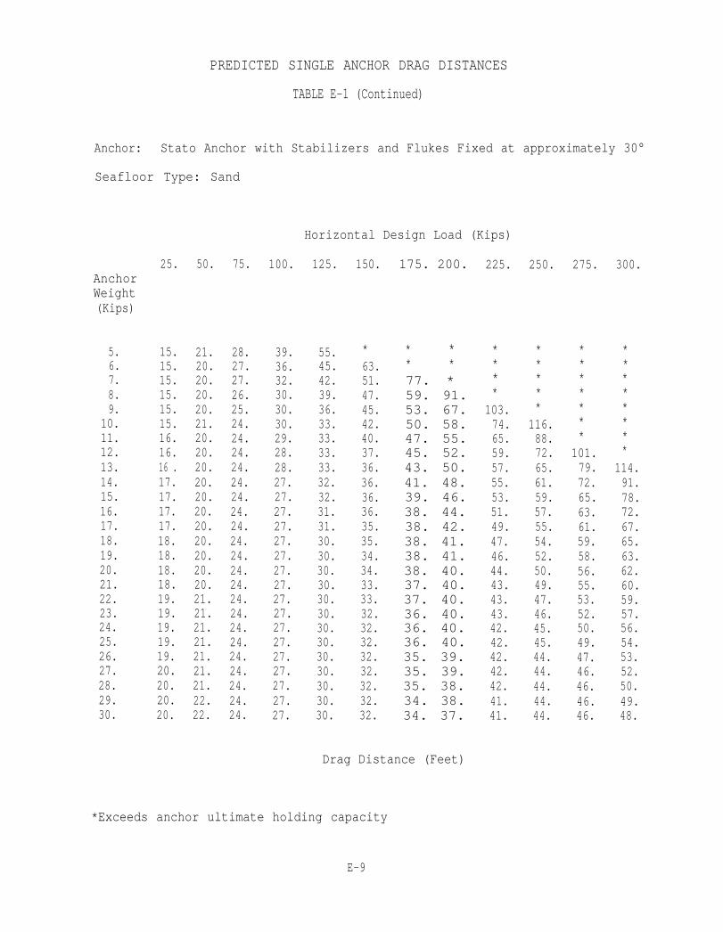
PREDICTED SINGLE ANCHOR DRAG DISTANCES
TABLE E-1 (Continued)
Anchor: Stato Anchor with Stabilizers and Flukes Fixed at approximately 30°
Seafloor Type: Sand
Horizontal Design Load (Kips)
AnchorWeight(Kips)
5.6.7.8.9.
10.11.12.13.14.15.16.17.18.19.20.21.22.23.24.25.26.27.28.29.30.
25.
15.15.15.15.15.15.16.16.16 .17.17.17.17.18.18.18.18.19.19.19.19.19.20.20.20.20.
50.
21.20.20.20.20.21.20.20.20.20.20.20.20.20.20.20.20.21.21.21.21.21.21.21.22.22.
75.
28.27.27.26.25.24.24.24.24.24.24.24.24.24.24.24.24.24.24.24.24.24.24.24.24.24.
100.
39.36.32.30.30.30.29.28.28.27.27.27.27.27.27.27.27.27.27.27.27.27.27.27.27.27.
125.
55.45.42.39.36.33.33.33.33.32.32.31.31.30.30.30.30.30.30.30.30.30.30.30.30.30.
150.
*63.51.47.45.42.40.37.36.36.36.36.35.35.34.34.33.33.32.32.32.32.32.32.32.32.
175. 200.
* ** *77. *59. 91.53. 67.50. 58.47. 55.45. 52.43. 50.41. 48.39. 46.38. 44.38. 42.38. 41.38. 41.38. 40.37. 40.37. 40.36. 40.36. 40.36. 40.35. 39.35. 39.35. 38.34. 38.34. 37.
225.
****
103.74.65.59.57.55.53.51.49.47.46.44.43.43.43.42.42.42.42.42.41.41.
250.
*****
116.88.72.65.61.59.57.55.54.52.50.49.47.46.45.45.44.44.44.44.44.
275.
*******
101.79.72.65.63.61.59.58.56.55.53.52.50.49.47.46.46.46.46.
300.
********
114.91.78.72.67.65.63.62.60.59.57.56.54.53.52.50.49.48.
Drag Distance (Feet)
*Exceeds anchor ultimate holding capacity
E-9
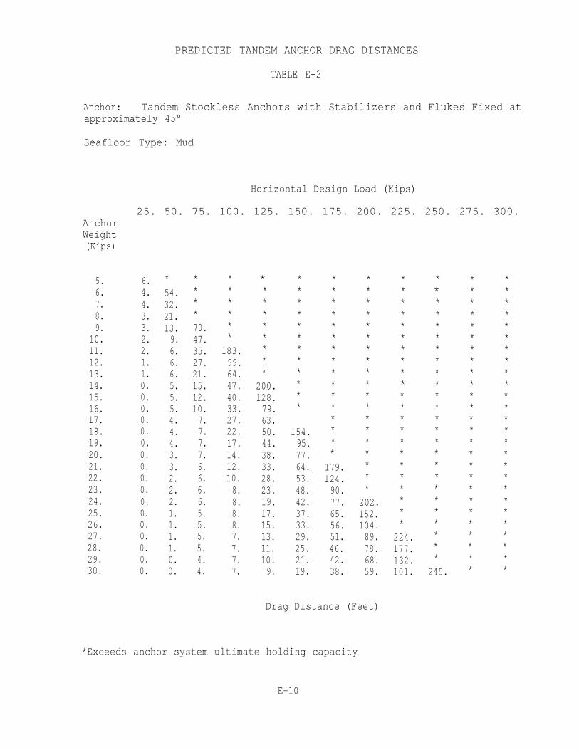
PREDICTED TANDEM ANCHOR DRAG DISTANCES
TABLE E-2
Anchor: Tandem Stockless Anchors with Stabilizers and Flukes Fixed atapproximately 45°
Seafloor Type: Mud
Horizontal Design Load (Kips)
25. 50. 75. 100. 125. 150. 175. 200. 225. 250. 275. 300.AnchorWeight(Kips)
5.6.7.8.9.
10.11.12.13.14.15.16.17.18.19.20.21.22.23.24.25.26.27.28.29.30.
6.4.4.3.3.2.2.1.1.0.0.0.0.0.0.0.0.0.0.0.0.0.0.0.0.0.
*54.32.21.13.9.6.6.6.5.5.5.4.4.4.3.3.2.2.2.1.1.1.1.0.0.
****70.47.35.27.21.15.12.10.7.7.7.7.6.6.6.6.5.5.5.5.4.4.
******
183.99.64.47.40.33.27.22.17.14.12.10.8.8.8.8.7.7.7.7.
*********
200.128.79.63.50.44.38.33.28.23.19.17.15.13.11.10.9.
************
154.95.77.64.53.48.42.37.33.29.25.21.19.
****************
179.124.90.77.65.56.51.46.42.38.
*******************
202.152.104.89.78.68.59.
Drag Distance (Feet)
**********************
224.177.132.101.
*************************
245.
**************************
**************************
*Exceeds anchor system ultimate holding capacity
E-10

PREDICTED TANDEM ANCHOR DRAG DISTANCES
TABLE E-2 (Continued)
Anchor: Tandem Stockless Anchors with Stabilizers and Flukes Fixed atapproximately 36°
Seafloor Type: Sand
Horizontal Design Load (Kips)
AnchorWeight(Kips)
5.6.7.8.9.
10.11.1213.14.15.16.17.18.19.20.21.22.23.24.25.26.27.28.29.30.
25. 50.
13. 20.13. 19.13. 18.13. 17.13. 17.13. 17.13. 17.13. 17.13. 17.13. 17.13. 17.13. 17.13. 17.13. 17.13. 18.13. 18.13. 18.13. 18.13. 18.14. 18.14. 18.14. 17.14. 17.14. 17.14. 17.14. 17.
75.
32.27.25.24.23.22.21.21.20.20.20.20.20.20.20.20.20.20.20.20.20.20.20.21.21.21.
100.
**37.33.29.28.27.26.26.25.24.24.23.23.23.23.22.22.22.22.22.22.23.23.23.23.
125. 150. 175.
* * ** * ** * ** * *42. * *38. * *34. 46. *32. 43. *31. 39. *30. 37. 47.29. 35. 44.29. 34. 41.28. 33. 39.28. 32. 37.27. 32. 36.27. 31. 35.26. 31. 35.26. 30. 34.26. 30. 34.25. 29. 33.25. 29. 33.25. 28. 32.25. 28. 32.25. 28. 32.25. 28. 31.25. 27. 31.
200.
***********52.49.46.44.41.40.39.38.37.36.36.36.35.35.35.
Drag Distance (Feet)
225.
**************53.50.48.46.44.42.41.40.40.39.38.38.
250.
****************57.54.52.50.48.46.45.43.43.42.
275.
*******************58.56.54.52.50.49.47.
300.
*********************62.60.58.56.54.
*Exceeds anchor system ultimate holding capacity
E-11
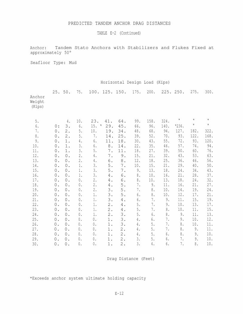
PREDICTED TANDEM ANCHOR DRAG DISTANCES
TABLE E-2 (Continued)
Anchor: Tandem Stato Anchors with Stabilizers and Flukes Fixed atapproximately 50°
Seafloor Type: Mud
Horizontal Design Load (Kips)
AnchorWeight(Kips)
5.6.7.8.9.
10.11.12.13.14.15.16.17.18.19.20.21.22.23.24.25.26.27.28.29.30.
25. 50.
4.0: 3.0. 2.0. 2.0. 1.0. 1.0. 1.0. 0.0. 0.0. 0.0. 0.0. 0.0. 0.0. 0.0. 0.0. 0.0. 0.0. 0.0. 0.0. 0.0. 0.0. 0.0. 0.0. 0.0. 0.0. 0.
75.
10.6.5.5.4.3.3.2.2.1.1.1.0.0.0.0.0.0.0.0.0.0.0.0.0.0.
100. 125. 150.
23. 41. 64.15. “10.7.6.6.5.4.4.3.3.3.2.2.2.1.1.1.1.1.0.0.0.0.0.0.
29. 45.19. 34.14. 25.11. 18.8. 14.7. 11.7. 9.6. 8.5. 7.5. 7.4. 6.4. 6.4. 5.3. 5.3. 5.3. 4.2. 4.2. 4.2. 3.1. 3.1. 3.1. 2.1. 2.1. 2.1. 2.
175.
99.66.48.39.30.22.18.15.12.10.9.8.8.7.7.6.6.5.5.5.4.4.4.4.3.3.
200.
158.96.68.52.43.35.27.21.18.15.13.10.10.9.8.8.7.7.7.6.6.5.5.5.5.4.
Drag Distance (Feet)
225. 250.
324.140.94.70.55.46.39.32.25.21.18.16.13.11.10.10.9.9.8.8.7.7.7.6.6.6.
*“236.127.93.72.57.50.43.36.29.24.21.18.16.14.12.11.10.10.9.9.8.8.8.7.7.
275.
**
182.122.93.74.60.53.46.40.34.28.24.21.19.17.15.13.11.11.10.10.9.9.9.8.
300.
**
322.168.120.94.76.63.56.50.43.37.32.27.24.21.19.17.15.13.12.11.11.10.10.10.
*Exceeds anchor system ultimate holding capacity
E-12
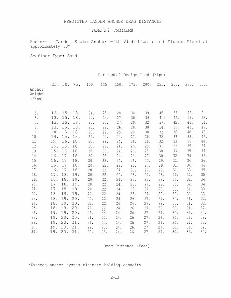
PREDICTED TANDEM ANCHOR DRAG DISTANCES
TABLE E-2 (Continued)
Anchor: Tandem Stato Anchor with Stabilizers and Flukes Fixed atapproximately 30°
Seafloor Type: Sand
Horizontal Design Load (Kips)
25. 50. 75.AnchorWeight(Kips)
5.6.7.8.9.
10.11.12.13.14.15.16.17.18.19.20.21.22.23.24.25.26.27.28.29.30.
12. 15. 18.13. 15. 18.13. 15. 18.13. 15. 18.14. 15. 18.14. 15. 18.15. 16. 18.15. 16. 18.15. 16. 18.16. 17. 18.16. 17. 18.16. 17. 18.16. 17. 18.17. 18. 19.17. 18. 19.17. 18. 19.17. 18. 19.18. 19. 19.18. 19. 20.18. 19. 20.18. 19. 20.19. 19. 20.19. 20. 20.19. 20. 21.19. 20. 21.19. 20. 21.
100.
21.20.20.20.20.21.20.20.20.20.20.20.20.20.20.20.20.21.21.21.21.21.21.21.22.22.
125.
25.24.23.22.22.22.22.22.23.23.22.22.22.22.22.22.22.22.22.22.22.22.22.22.23.23.
150.
28.27.27.26.25.24.24.24.24.24.24.24.24.24.24.24.24.24.24.24.24.24.24.24.24.24.
175.
34.30.29.28.28.27.26.26.26.26.26.26.26.26.26.26.26.26.26.26.26.26.26.26.26.26.
200.
39.36.32.30.30.30.29.28.28.27.27.27.27.27.27.27.27.27.27.27.27.27.27.27.27.27.
225.
45.41:37.34.32.32.32.31.30.30.29.29.28.28.28.29.29.29.29.29.29.29.29.29.29.29.
250.
55.45.42.39.36.33.33.33.33.32.32.31.31.30.30.30.30.30.30.30.30.30.30.30.30.30.
275.
78.52.46.43.40.38.35.35.35.34.34.34.33.32.32.32.31.31.31.31.31.31.31.31.31.31.
300.
*63.51.47.45.42.40.37.36.36.36.36.35.35.34.34.33.33.32.32.32.32.32.32.32.32.
Drag Distance (Feet)
*Exceeds anchor system ultimate holding capacity
E-13

![Numerical model validation for mooring systems: Method and ...123 (PTO) system [4]. Consequently, the mooring system is commonly represented in a simplified form which does not 124](https://img.dokumen.tips/doc/110x75/5e6dda2a309954236967b62a/numerical-model-validation-for-mooring-systems-method-and-123-pto-system.jpg)