Embed Size (px)
Citation preview

Instruction manual
Solutions for Drives
Fuji Electric low noise high performance inverter
Single-phase 200V input FVR-E11S-7ENThree-phase 400V input FVR-E11S-4EN
E11S
FVR
MGB_E11S15.FM Page 1 Saturday, September 15, 2001 1:21 PM

FVR-E11S-EN
Contents
Safety precautions .................................... 1
1 Before Using the Inverter ............... 1-11-1 Receiving Inspection ..................... 1-11-2 External view of Product ............... 1-21-3 Handling the Product .................... 1-31-4 Transportation ............................... 1-41-5 Storage ......................................... 1-4
2 Installation and Connection ........... 2-12-1 Operating Environment ................. 2-12-2 Installation Method ........................ 2-12-3 Connection .................................... 2-2
2-3-1 Basic Connection ................... 2-22-3-2 Connection of Main Circuit and
Grounding Terminal ................ 2-42-3-3 Connection of Control
Terminal .................................. 2-62-3-4 Terminal Layout .................... 2-112-3-5 Applicable Devices and Cable
Sizes for Main Circuit ........... 2-12
3 Operation ............................................ 3-13-1 Inspection and Preparation
Before Operation .......................... 3-13-2 Operation Method ......................... 3-23-3 Test Operation .............................. 3-2
4 Keypad Panel ..................................... 4-14-1 Appearance of Keypad Panel ....... 4-1
4-1-1 Upon an Alarm ....................... 4-44-1-2 Digital Frequency
Setting Method ....................... 4-4
5 Selecting Functions ......................... 5-15-1 Function Selection List .................. 5-15-2 Detail Description of
Each Function ............................. 5-12Fundamental Functions (F Functions) ................................... 5-12Extension Terminal Functions (E Functions) ................................... 5-25Control Functions of Frequency (C Functions).................................... 5-33Motor Parameters (P Functions) ................................... 5-36High Performance Functions (H Functions) ................................... 5-39Alternative Motor Parameters (A Functions) ................................... 5-53Optional Functions(O Functions) ................................... 5-55
6 Protective Operation ........................ 6-16-1 List of Protective Operations ......... 6-16-2 Alarm Reset .................................. 6-3
7 Troubleshooting ............................... 7-17-1 When Protective Function
Goes active ................................... 7-17-2 When Motor rotates Incorrectly ..... 7-6
8 Maintenance and Inspection .......... 8-18-1 Daily Inspection ............................. 8-18-2 Periodic Inspection ........................ 8-18-3 Measurement of Electrical
Amounts in Main Circuit ................ 8-58-4 Insulation Test ............................... 8-68-5 Replacement Parts ........................ 8-78-6 Inquiries about Product and
Guarantee ..................................... 8-7
9 Specifications .................................... 9-19-1 Standard Specifications ................ 9-1
9-1-1 Single-phase 200V input ........ 9-19-1-2 Three-phase 400V input ......... 9-2
9-2 Common Specifications ................ 9-39-3 External Dimensions ..................... 9-89-4 RS 485 Communication .............. 9-10
9-4-1 Connector and Communication Cable ........... 9-11
9-4-2 Recommended RS-232C/RS485 Converter .. 9-11
9-4-3 Remote/local changeover ..... 9-119-4-4 Communication Protocol ...... 9-129-4-5 Standard Frame .................... 9-149-4-6 Short Frame .......................... 9-169-4-7 Details of Frame ................... 9-189-4-8 Broadcasting ......................... 9-189-4-9 Communication Error Code .. 9-199-4-10 Data Type .............................. 9-199-4-11 Function Code List ................ 9-209-4-12 Data Format .......................... 9-24
10 Options .............................................. 10-110-1 External Options ......................... 10-1
11 Applicable Reactor ......................... 11-1
12 Electromagnetic compatibility (EMC) ........................ 12-112-1 General ....................................... 12-112-2 Recommended Installation .......... 12-112-3 The harmonics restriction in EU .. 12-212-4 RCD Installation .......................... 12-2
MGB_E11S13.FM Page 1 Saturday, September 15, 2001 1:20 PM

Safety precautions 1
FVR-E11S-EN
IntroductionThank you for purchasing our FVR-E11S seriesinverter.This product is designed to drive a three-phaseinduction motor. Read through this instructionmanual and be familiar with the handling methodfor correct use.Improper handling blocks correct operation orcauses a short life or failure.Have this manual delivered to the final user ofthe product. Keep this manual in a safe place un-til the inverter is discarded.For the usage of optional equipment, refer to themanuals for optional equipment.
Safety precautions
Read through this manual before starting instal-lation, connection (wiring), operation, or mainte-nance and inspection for correct use. Be familiarwith the knowledge about the device, informati-on about safety, and all the precautions beforestarting operation.The safety precautions are classified into the fol-lowing categories in this manual.
Negligence of the description under the CAUTIONtitle can cause serious results in certain circum-stances.These safety precautions are important andmust be observed at any time.
Purposes
Installation
WARNINGNegligence of the description can cau-se dangers including deaths or seriousinjuries.
CAUTIONNegligence of the description cancause dangers including intermediateor slight injuries or material losses.
WARNING
1. FVR-E11S is designed to drive a three-phase induction motor. Do not use it forsingle-phase motors or for other purposes.Otherwise fire could occur!
2. FVR-E11S may not be used for a life-sup-port system or other purposes directly rela-ted to the human safety.
3. Though FVR-E11S is manufactured understrict quality control, install safety devicesfor applications where serious accidents ormaterial losses are foreseen in relation tothe failure of it.Otherwise an accident could occur!
WARNING
1. Install the inverter on a nonflammablematerial such as metal.Otherwise fire could occur!
2. Do not place flammable matter nearby. Otherwise fire could occur!
MGB_E11S00.FM Page 1 Saturday, September 15, 2001 1:42 PM

FVR-E11S-EN
2 Safety precautions
Wiring
CAUTION
1. Do not hold the cover during transportati-on.Otherwise the inverter may drop and cause injuries!
2. Do not allow lint, paper, wood chips, dust,metallic chips or other foreign matter in theinverter or do not allow them attached tothe heat sink. Otherwise fire or an accident could occur!
3. Do not install or operate an inverter whichis damaged or lacking parts.Otherwise fire, an accident or injuries could occur!
WARNING
1. When connecting the inverter to the powersupply, add a circuit breaker for circuit pro-tection and earth leakage breaker in thepath of power supply. Otherwise fire could occur!
2. Be sure to connect the grounding cablewithout fail. Otherwise electric shock or fire could occur!
3. Both screws of grounding terminals ofFVR5.5/7.5E11S-4EN has to be tightenedup securely even if one grounding terminalis not used. Otherwise electric shock or fire could occur!
4. Qualified electricians should carry outwiring.Otherwise electric shock could occur!
5. Perform wiring after checking that thepower supply is turned off.Otherwise electric shock could occur!
6. Be sure to perform wiring after installingthe main body of the inverter.Otherwise electric shock or injuries could occur!
CAUTION
1. Check that the number of phases and therated voltage of the product agree with thenumber of phases and the voltage of theAC power supply.Otherwise fire or an accident could occur!
2. Do not connect the AC power cables to theoutput terminals (U, V, W).Otherwise fire or an accident could occur!
3. Do not connect a braking resistor directly tothe DC terminals (P (+), N (-)). Otherwise fire or an accident could occur!
4. The inverter, motor and wiring generateelectric noise. Take care of malfunction ofthe nearby sensors and devices.Otherwise an accident could occur!
MGB_E11S00.FM Page 2 Saturday, September 15, 2001 1:42 PM

Safety precautions 3
FVR-E11S-EN
Operation
Maintenance and inspection and parts replacement
WARNING
1. Be sure to install the terminal cover beforeturning the power on. Do not remove thecover during power application.Otherwise electric shock could occur!
2. Do not operate switches with wet hands. Otherwise electric shock could occur!
3. If the retry function has been selected, theinverter may automatically restart accor-ding to some causes after tripping. (Design the machine so that human safetyis ensured after restarting.) Otherwise an accident could occur!
4. If the torque limit function has been selec-ted, the inverter may operate at an accele-ration/deceleration time or speed differentfrom the set ones. Design the machine sothat safety is ensured even in such cases.Otherwise an accident could occur!
5. The STOP key is only effective whenfunction setting has been established tomake the STOP key enable. Prepare anemergency stop switch separately. Otherwise an accident could occur!
6. If an alarm reset is made with the operationsignal turned on, a sudden start will occur.Check that the operation signal is turnedoff in advance.Otherwise an accident could occur!
7. Do not touch the inverter terminals duringpower applies to the inverter even if the in-verter stops.Otherwise electric shock could occur!
CAUTION
1. Do not turn the main circuit power on or offto start or stop inverter operation. Otherwise failure could occur.
2. Do not touch the heat sink and braking re-sistor because they become very hot. Otherwise burns could occur!
3. Setting the inverter to high speeds is easy.Check the performance of the motor andmachines before changing the setting. Otherwise injuries could occur!
4. The brake function of the inverter does notprovide mechanical holding means. Injuries could occur!
WARNING
1. Turn the power off and wait for at least fiveminutes before starting inspection. (Further, check that the charge lamp isunlit, and check the DC voltage across theP (+) and N (-) terminals to be lower than25V DC.).Otherwise electric shock could occur!
2. Maintenance and inspection and parts re-placement should be made only by quali-fied persons. (Take off the watch, rings and other metal-lic matter before starting work. Use insula-ted tools.).Otherwise electric shock or injuriescould occur!
MGB_E11S00.FM Page 3 Saturday, September 15, 2001 1:42 PM

FVR-E11S-EN
4 Safety precautions
Disposal
Others
Conformity to Low Voltage Directive in EU
[Available only for the products with CE or TÜV mark]
CAUTIONHandle the inverter as an industrialwaste when disposing of it. Otherwise injuries could occur!
WARNINGNever remodel. Otherwise electric shock or injuriescould occur!
CAUTION
1. Safe separation for control interface of thisinverter is provided when this inverter isinstalled in overvoltage category II.PELV(Protective Extra Low Voltage) circuit orSELV(Safety Extra Low Voltage) circuit fromexternal controller is connected to the inter-face directly.
2. Basic insulation for control interface of this in-verter is provided when this inverter is installedin overvoltage category III. An insulation trans-former has to be installed between power sup-ply mains and this inverter when SELV circuitfrom external controller is connected to this in-verter directly. Otherwise supplementary insu-lation between control interface of this inverterand environment must be provided.
3. The ground terminal G should always beconnected to the ground. Don't use onlyRCD as the sole method of electric shockprotection.Dimensions of external PE conductorshould be same as dimensions of inputphase conductor and capable for possiblefault.
4. Use MCCB or MC that conforms to EN orIEC standard.
5. Where RCD (Residual-current-operatedprotective device) is used for protection incase of direct or indirect contact, only RCDof type B is allowed on the supply side ofthis EE (Electric equipment). Otherwiseanother protective measure shall be app-lied such as separation of the EE from theenvironment by double or reinforced insu-lation or isolation of EE and supply systemby the transformer.
6. The inverter has to be installed in environ-ment of pollution degree 2. If the environ-ment is pollution degree 3 or 4, the inverterhas to be installed in a cabinet of IP54 orhigher.
7. Use a prescribed wire according to theEN60204 Appendix C.
8. Install the inverter, AC or DC reactor, inputor output filter in an enclosure that meetsthe following requirement, to prevent a hu-man body from touching directly to theseequipment.
1) When a person can touch easily oneach connecting terminal or live parts,install the inverter, AC or DC reactor,output filter in an enclosure with mini-mum degree of protection of IP4X.
2) When a person can not touch easily oneach connecting terminal or live parts,install the inverter, AC or DC reactor,output filter in an enclosure with a mini-mum degree of protection of IP2X.
MGB_E11S00.FM Page 4 Saturday, September 15, 2001 1:42 PM

Safety precautions 5
FVR-E11S-EN
Caution for UL/cUL requirement
[Available only for the products with UL/cUL mark]
9. It is necessary to install the inverter in ap-propriate method using an appropriateRFI filter to conform to the EMC directive.It is customer's responsibility to checkwhether the equipment ,the inverter is in-stalled in, conforms to EMC directive.
10. Do not connect copper wire to groundingterminal directly. Use cramp terminal withtin or equivalent plating to reduce electro-chemical potential.
11. Do not remove the keypad panel beforedisconnecting power and do not insert/re-move the extension cable for keypad pa-nel remote operation while power is on.Confirm that the extension cable is secu-rely latched to keypad panel and inverterbefore power is on. A supplementary isolation is required forthe extension cable when the inverter is in-stalled in overvoltage category III.
12. Basic insulation for control interface of thisinverter is provided when the inverter isused at altitude over 2000m. The use at al-titude over 3000m is not permitted.
13. The supply mains neutral has to beearthed for FVR-E11S-4EN.
CAUTION
1. Take care of electric shock. Be sure to turnthe inverter off before starting work.
2. When the charge lamp is lit, the inverter isstill charged at a dangerous voltage.
WARNING
1. There are two or more live parts inside theinverter.
2. The inverter is approved as a part usedinside a panel. Install it inside a panel.
3. Perform wiring to the input, output andcontrol terminals of the inverter, referringto the table next page. Use UL certifiedround crimp terminal to the input and out-put terminals with insulation cover or co-vered with reduced tube to obtain theinsulation distance. Use a crimping tool re-commended by the terminal manufacturerwhen fabricating crimp terminals.
4. Install a fuse or circuit breaker betweenthe power supply and the inverter, refer-ring to the table next page.
5. The inverters FVR0.1 to 2.2E11S-7 aresuitable for use on a circuit capable or de-livering not more than 20,000 rms symme-trical amperes, 240V maximum.
6. The inverters FVR0.4 to 7.5E11S-4 aresuitable for use on a circuit capable or de-livering not more than the following sym-metrical amperes, 480V maximum. When the fuse is installed : 20.000AWhen the circuit breaker is installed:5000A
7. FVR-E11S-EN is an open type inverter.
8. A class 2 circuit wired with class 1 wire.
MGB_E11S00.FM Page 5 Saturday, September 15, 2001 1:42 PM

6 Safety precautions
FVR-E11S-EN
Inverter type
Tightening torque [N·m]
Applicable wire diameter[AWG] (mm2) 1)
Fuse 2)
[A]Breaker
[A]
L1/R, L2/S, L3/T
L1/L, L2/NP1,P(+)DB,N(-)U, V, W
Controlsection
L1/R, L2/S, L3/T
L1/L, L2/N G
P1,P(+)DB,N(-)U, V, W
Controlsection
FVR0.1E11S-7EN
1.2
0.4
14 (2.1)20
(0.5)
6 5
FVR0.2E11S-7EN 6 5
FVR0.4E11S-7EN 10 10
FVR0.75E11S-7EN
1.8
15 15
FVR1.5E11S-7EN 12 (3.3) 30 30
FVR2.2E11S-7EN 10 (5.3) 40 40
FVR0.4E11S-4EN
1.8
0.4
14 (2.1)20
(0.5)
6 5FVR0.75E11S-4EN
FVR1.5E11S-4EN 10 10
FVR2.2E11S-4EN 15 15
FVR4.0E11S-4EN 20 20
FVR5.5E11S-4EN3.5
12 (3.3) 30 30
FVR7.5E11S-4EN 10 (5.3) 40 40
1) Use copper wires of allowable maximum temperature 60 or 75 ˚C.
2) Use UL certified AC600V "Class J fuse."
GENERAL PRECAUTIONSDrawings in this manual may be illustrated without covers or safetyshields for explanation of detail parts. Restore the covers and shieldsin the original state and observe the description in the manual beforestarting operation.
MGB_E11S00.FM Page 6 Saturday, September 15, 2001 1:42 PM
1 Before Using the Inverter 1-1
FVR-E11S-EN
1
1 Before Using the Inverter
1-1 Receiving Inspection
Unpack and check the following items.If you have any problems with the product,contact the dealer or the nearest branch of FujiElectric Co., Ltd.
Ratings nameplate
1. Check the ratings nameplate to confirm thatthe delivered product is the ordered one.
TYPE: Type of inverter
FVR 0.4 E11S-7 ENVersionPower voltage system:7: Single-phase 200V class4: Three-phase 400V classSeries name: E11SNominal applicablemotor capacity:0.4: 0.4 kWProduct type
SOURCE: Number of input phases, inputvoltage, input frequency, inputcurrent
OUTPUT: Number of output phases, ratedoutput capacity, rated outputvoltage, output frequency range,rated output current, overloadcurrent rating
SER. NO.: Product number
1 1 0113R0001Serial number ofproduction lotProduction month:1 to 9: January to September,X: October, Y: November, Z: DecemberProduction year: Last digit of year (1 2001)
2. Check for breakage, missing parts, and dentsor other damage on the cover and the mainbody given during transportation.
3. Instruction manual and complete inverter isincluded.
MGB_E11S01.FM Page 1 Saturday, September 15, 2001 1:10 PM

FVR-E11S-EN
1-2 1 Before Using the Inverter
1
1-2 External view of Product
Fig 1-2-1 Overall view (4.0kW or below)
Fig 1-2-2 Overall view (5.5, 7.5kW)
Fig 1-2-3a View of wiring part (4.0kW or below)
Fig 1-2-3b View of wiring part (4.0kW or below)
A barrier is provided in the main circuit terminalblock cover for the P1, P (+), DB and N (-) cableport. Cut the barrier using nippers or the likebefore wiring.
Fig 1-2-4 View of wiring part (5.5, 7.5kW)
A barrier is provided in the cable cover for theP1, P (+), DB and N (-) cable port. Cut the barrierusing nippers or the like before wiring.
Keypadpanel
Controlterminalblock cover
Ratingsname-plate
Keypad panel mounting screw
Maincircuitterminalblockcover
Inter-mediatecover
Inter-mediatecover
Keypadpanel
Keypadpanelmountingscrew
Ratingsname-plateTerminal
blockcover
Control cable port
P1, P(+), DB, N(-) cable port
L1/R, L2/S, L3/T (L1/L, L2/N), U, V, W cable port
Grounding cable port
Control cable port
P1, P(+), DB, N(-) cable port
L1/R, L2/S, L3/T (L1/L, L2/N), U, V, W cable port
Grounding cable port
Control cable port
L1/R, L2/S, L3/T cable port
P1, P(+), DB, N(-) cable port
U, V, W cable port
Cable cover
Grounding cable port
Terminal block cover
MGB_E11S01.FM Page 2 Saturday, September 15, 2001 1:10 PM

1 Before Using the Inverter 1-3
FVR-E11S-EN
1
1-3 Handling the Product
1) Removing the control terminal block cover (4.0kW or below)While lightly pushing the sides of the controlterminal block cover at the catches, lift the co-ver in the procedure shown in Fig. 1-3-1 to re-move it.
Figure 1-3-1 Removing the control terminal block cover
2) Removing the main circuit terminal blockcover (4.0kW or below)While lightly pushing the sides of the maincircuit terminal block cover at the catches,slide toward you in the procedure shown inFig. 1-3-2 to remove it.
Figure 1-3-2 Removing the main circuit terminal blockcover
3) Removing the terminal block cover (5.5, 7.5kW )Loose the screws indicated below and whilelightly pushing the sides of the terminal blockcover at the catches, lift the cover in theprocedure shown in Fig. 1-3-3 to remove it.
Figure 1-3-3 Removing the terminal block cover
4) Removing the keypad panelLoosen the keypad panel mounting screwsand remove the keypad panel in theprocedure shown in Fig. 1-3-4. During theprocedure, slowly remove the keypad panelright toward the top. If the keypad panel ishandled abruptly, the connector will bebroken.
Figure 1-3-4 Removing the keypad panel
Reverse the procedures to mount the terminalblock cover and keypad panel.
screws
screws
MGB_E11S01.FM Page 3 Saturday, September 15, 2001 1:10 PM

FVR-E11S-EN
1-4 1 Before Using the Inverter
1
1-4 Transportation
Always hold the main unit when carrying the in-verter.If covers or parts are held, the inverter may bebroken or it may drop.
1-5 Storage
To store temporarilyStore the inverter in an environment described inTable 1-5-1.
Table 1-5-1 Storage environment
Note 1: The storage temperature is for ashort time during transportation orthe like.
Note 2: Even if the humidity is within the re-quirements of the specifications, pla-ces with abrupt temperaturechanges are subject to condensati-on or freezing. Avoid storing the in-verter in such places.
1. Do not place the inverter directly on the floor.
2. If the ambient atmosphere is adverse, wrapthe inverter in a vinyl sheet or the like whenstoring.
3. If humidity may give an ill effect, add a dryingagent (such as silica gel) in the packageprepared as described in item (2.).
To store for a long timeThe long-term storage method of the inverter va-ries largely according to the environment of thestorage site.
General storage methods are described below:
1. The storage site must satisfy the require-ments of specifications for temporary stora-ge.However, for storage exceeding threemonths, the upper limit of the ambienttemperature shall not exceed 30 ˚C. This isfor the prevention of deterioration of electro-lytic capacitors left turned off.
2. The package must be air tight so that moisturewill not enter. Add a drying agent inside thepackage to contain the relative humidity insidethe package within 70%.
3. The inverter installed on a unit or control pa-nel and left is likely to be exposed to moistureand dust. If this is the case, remove the inver-ter and move it to a preferable environment.
4. Electrolytic capacitors left turned off for anextended period of time deteriorate. Do notstore for one year or more without turning thepower on.
Item Specifications
Ambienttemperature
-10 to+50 ˚C
Places not subjected to abrupt tempera-ture changes or con-densation or freezing
Storagetemperature
(Note 1)
-25 to+65 ˚C
Relativehumidity
5 to 95%
(Note 2)
Atmosphere
The product must not be exposed to dust, direct sunlight, corrosive or flammable gases, oil mist,vapor, water drops or vibration. There must be little salt in theatmosphere.
Atmosphericpressure
During storage: 86 to 106 kPaDuring transportation: 70 to 106 kPa
MGB_E11S01.FM Page 4 Saturday, September 15, 2001 1:10 PM

2 Installation and Connection 2-1
FVR-E11S-EN
2
2 Installation and Connection
2-1 Operating Environment
Install the inverter in an environment describedin Table 2-1-1.
Table 2-1-1 Operating environment
Table 2-1-2 Output attenuation ratio in relation to altitude
2-2 Installation Method
1. Tightly mount the inverter in the upright positi-on on a rigid structure so that the "FVR-E11"characters face front. Avoid mounting the in-verter upside down or avoid mounting horizon-tally.
2. Allow clearances for cooling wind shown inFig. 2-2-1 to cool down the inverter which ge-nerates heat during operation. The generatedheat is radiated upward. Do not install the in-verter below a heat sensitive device.
Figure 2-2-1
3. The temperature of the heat sink rises toabout 90 degrees C during operation of theinverter. Mount the inverter on a base madeof a material withstanding the temperature ri-se.
Item Specifications
Site Indoors
Ambienttemperature
-10 to +50
°C
Relativehumidity
5 to 95% (without condensation)
Atmosphere
The inverter must not be exposed to dust, direct sunlight, corrosive ga-ses, oil mist, vapor or water drops.There must be little salt.No condensation occurs due to ab-rupt temperature changes.
Altitude1,000 m max. (Refer to Table 2-1-2 for altitudes exceeding 1000 m.)
Atmosphericpressure
86 to 106 kPa
Vibration
3 mm 2 to 9 Hz, 9,8 m/s2 9 to 20 Hz,2 m/s2 20 to 55 Hz,1 m/s2 55 to 200 Hz,
Altitude Output current attenuation ratio
1000 m or less 1.00
1000 - 1500 m 0.97
1500 - 2000 m 0.95
2000 - 2500 m 0.91
2500 - 3000 m 0.88
RightLeft
Above
Below
Main body
WARNINGInstall the inverter on a nonflammablematerial such as metal.Otherwise fire could occur.
MGB_E11S02.FM Page 1 Saturday, September 15, 2001 1:10 PM

FVR-E11S-EN
2-2 2 Installation and Connection
2
4. When installing the inverter inside a controlpanel or the like, take full consideration forventilation so that the ambient temperature ofthe inverter does not exceed the specificationrequirements. Do not install the inverter in apoorly ventilated small enclosure.
5. When storing multiple inverters inside a sin-gle unit or inside a control panel, horizontalinstallation is recommended to reduce mutualtemperature effects. When an vertical layoutis adopted for an unavoidable reason, installa partition plate or the like between invertersto isolate the heat of the lower inverter.
2-3 Connection
Remove the control terminal block cover toconnect the control terminal block. Remove themain circuit terminal block cover to connect themain circuit terminal block. Correctly connectcables taking care of the following precautions.
2-3-1 Basic Connection1. Be sure to connect the power cables to main
circuit power terminals L1/R, L2/S and L3/Tor L1/L,L2/N of the inverter. If the power ca-bles are connected to other terminals, the in-verter will be broken. As well, check thesource voltage for the allowable voltage ran-ge specified on the nameplate and so on.
2. Connect the grounding terminal without failaccording to national or local electric code toprevent electric shock, fire or other disastersand to reduce electric noise.
3. Use reliable crimp terminals for connection ofcables to the terminals.
4. After finishing wiring, check the following.
a) Check if the cables are connected correct-ly.
b) Check if there is no failure of connection.
c) Check if terminals or cables are short cir-cuited or there is a ground fault.
5. To change connection of an inverter havingbeen turned on.The smoothing capacitor in the direct currentpart of the main circuit takes time to be di-scharged after it is turned off. To avoid danger, check the DC voltage(across main circuit terminals P (+) and N (-))for a safety voltage (25 V DC or lower) usinga multi-meter, after the charge lamp is unlit.Wait until the residual voltage is dischargedbefore shorting a circuit, to avoid being hit bysparks caused by the voltage (electric char-ge).
CAUTIONDo not allow lint, paper, wood chips,dust, metallic chips or other foreignmatter in the inverter or do not allowthem attached to the heat sink. Otherwise fire or an accident couldoccur.
WARNING
1. Be sure to connect the grounding cablewithout fail.Otherwise electric shock or fire couldoccur.
2. Qualified electricians should carry out wi-ring.Otherwise electric shock could occur.
3. Perform wiring after checking that thepower supply is turned off.Otherwise electric shock could occur.
MGB_E11S02.FM Page 2 Saturday, September 15, 2001 1:10 PM

2 Installation and Connection 2-3
FVR-E11S-EN
2
Basic connection diagram Electric cabinet
Figure 2-3-1
*1) Supply a source voltage suitable for the rated voltage of the inverter.*2) Optional part. Use when necessary.*3) Peripheral equipment. Use when necessary.*4) To connect a DC reactor (DCR) for power factor correcting, remove the jumper between the P1 and P (+)
terminals.
Leistungs-kreis
Kompakt-leistungs-schalter oder Fehler-stromschutz-schalter 3)
Netz-spannung 1)
3-phasig400 bis 480 V50/60 Hz
Externe Ein-speisungSteuer-spannung 7)
Erdung Erdung
Motor
Bewehrtes oder abgeschirmtesKabel
Stör-melde-relais
Source Sink(Positiv- Negativlogik)
Steuerkreis
0 bis+10 V DC
Relais-ausgang
Bidirek-tionaleTran-sistor-ausgänge
Impulsausgang
Digitalmeßgerät(Impulszähler) 2)
Digitaleingang
Analog-ein-gang
Potentiometer 2)
Spannungseingang0 bis +10 V DC
Analogmeßgerät0 bis 60 Hz FM 2)
Anstelle des Potentiometers können auch 0 bis ±10 V DC oder 0 bis ±5 V DC an die Klemmen [12]- [11] angelegt werden.
9)
Zweiter Spannungseingang 0 bis ±10 V DC (0 bis ±5 V DC)
oder Stromeingang4 bis 20 mA DC
8)
Bremseinheit 2) 6)
Externer Bremswiderstand 2) 5)
Zwischen-kreisdrossel(DCR) 2) 4)
22 to 27 Vdc
Analog output
Pulse output
MGB_E11S02.FM Page 3 Saturday, September 15, 2001 1:10 PM

2-4 2 Installation and Connection
FVR-E11S-EN
2
2-3-2 Connection of Main Circuit and Grounding Terminal
Table 2-3-1 Connection of Main Circuit and Grounding Terminal
Note: When a thermal relay is installed in the path between the inverter and the motor, or especiallyin the case of a 400V system, the thermal relay may malfunction even with a wiring lengthshorter than 50 m. In such a case, add an OFL filter or lower the Motor sound adjustment(carrier frequency) of the inverter. ... Function code F26 Motor sound adjustment.
Symbol Name of terminal Description
L1/R, L2/S, L3/T Main circuit power input Connects a 3-phase power supply.
L1/L, L2/N Main circuit power input Connects a 1-phase power supply.
U, V, W Inverter output Connects a 3-phase induction motor.
P1, P(+) For DC reactor Connects an optional DC reactor.
P(+), DB For external braking resistor
Connects an optional external braking resistor.
P(+), N(-) DC link circuit terminal Connected to DC link circuit.
G Grounding Grounding terminal of the inverter chassis (housing). Connect to the protective ground.
1) Main circuit power input terminal (L1/R, L2/S, L3/T, L1/L, L2/N)
1. Connect the main circuit power input terminalsto the power supply through a circuit breakerfor circuit (wiring) protection or an earth leaka-ge breaker. There is not need to match thephase sequence.
2. It is recommended to connect a magnetic con-tactor to disconnect the inverter from the po-wer supply to prevent a failure or accidentfrom becoming serious upon activation of theprotective function of the inverter.
3. Do not turn the main circuit power supply on oroff to start or stop the inverter. Instead, usecontrol circuit terminals FWD and REV or theRUN and STOP keys on the keypad panel. Ifit is unavoidable to turn the main circuit powersupply on or off to start or stop the inverter, li-mit the frequency to once an hour or fewer.
4. Do not connect to a single-phase power sup-ply for 3-phase input inverter.
2) Inverter output terminals (U, V, W)
1. Connect these terminals to a 3-phase motorwith the correct phase sequence. If the direc-tion of rotation does not match the operationdirection, change arbitrary two cables amongthe U, V and W phases.
2. Do not connect a phase advance capacitor orsurge absorber to the inverter output.
3. If the wiring length between the inverter andthe motor is extremely long, the stray capacitybetween cables causes a high frequency cur-rent, possibly tripping the inverter due to anovercurrent, increasing the leakage current, ordeteriorating the current detection accuracy tocause deterioration of the performance orother phenomena. To prevent such trouble, li-mit the wiring length of the motor to 50 m for4.0 kW or a smaller output or to 100 m for a lar-ger output.
MGB_E11S02.FM Page 4 Saturday, September 15, 2001 1:10 PM

2 Installation and Connection 2-5
FVR-E11S-EN
2
3) DC reactor connecting terminals (P1, P (+))
1. Use this terminal to connect a DC reactor (op-tion). Remove the jumper connected in thefactory before connecting the DC reactor.
2. Do not remove the jumper if no DC reactor isused.
Figure 2-3-1 DCR connection diagram
4) External braking resistor connecting terminals (P (+), DB)E11S is not equipped with a braking resistor.An external braking resistor (option) is neces-sary for frequent operation or heavy dutyinertia load operation to enhance the brakingperformance.
1. Connect the P (+) and DB terminals of theexternal braking resistor to the P (+) and DBterminals of the inverter.
2. Arrange devices so that the wiring length iswithin 5 m and twist or closely (in parallel)place the two cables.
Bild 2-3-2 Connection diagram
5) Inverter grounding terminal ( G)
Ground the grounding terminal G for safetyand noise reduction without fail. The metallicframe of electrical equipment must be groun-ded in accordance with national or local elec-tric code to avoid electric shock, fire and otherdisasters.
Inverter
External braking resistor (DB)DC reactor (DCR)
CAUTION
1. Check that the number of phases and therated voltage of the product agrees with thenumber of phases and the voltage of theAC power supply.
2. Do not connect the AC power cables to theoutput terminals (U, V, W).Otherwise injuries could occur.
3. Do not connect a braking resistor directly tothe DC terminals (P (+), N (-)).Otherwise fire could occur.
MGB_E11S02.FM Page 5 Saturday, September 15, 2001 1:10 PM

2-6 2 Installation and Connection
FVR-E11S-EN
2
2-3-3 Connection of Control Terminal
Table 2-3-2 shows the functions of the control circuit terminals. The me-thod of connecting control function terminals varies according to thefunction setting. Refer to the connection method for the function.
Classifica-tion
Terminalsymbol
Terminal name Description of function
Analoginput
13Potentiometerpower supply
+10 V power supply for frequency setting POT. (POT: 1 to 5 k
Ω).
12 Voltage input
1. The frequency is set according to the external analog input voltage command.• 0 to +10 V DC / 0 to 100 %• Reversible operation using +/- signal:
0 to +/- 10 V DC / 0 to 100 %• Inverse mode operation:: +10 to 0 V DC / 0 to 100 %
2. The PID control feedback signal is input.Input resistance: 22 k
Ω
C1 Current input
1. The frequency is set according to the analog input current command.
• 4 to 20 mA DC / 0 to 100 % • Inverse mode operation: 20 to 4 mA DC / 0 to 100 %2. The PID control feedback signal is input.Input resistance: 250
Ω11 Common Common for analog signals
MGB_E11S02.FM Page 6 Saturday, September 15, 2001 1:10 PM

2 Installation and Connection 2-7
FVR-E11S-EN
2
Classifica-tion
Terminalsymbol
Terminal name Description of function
Digitalinput
FWDForward operation command
Forward operation with FWD-P24 ON and deceleration and stop with FWD-P24 OFF.
REVReverse operation command
Reverse operation with REV-P24 ON and deceleration-stop with REV-P24 OFF.
X1 Digital input 1 A coast-to-stop command from an external device, external alarm, alarm reset, multi-step frequency selection and other functions can be assigned to the X1 through X5 terminals. Refer to the terminal function E01 to 05 setting method in sec-tion 5-2 Detail Description of Each Function.
<Digital input circuit specification>
X2 Digital input 2
X3 Digital input 3
X4 Digital input 4
X5 Digital input 5
P24Control unitpower supply
+24V DC power supply for control input.Maximum output current : 50mA
CM Common Common for digital input
Analogoutput / pulseoutput
FM(11:
Commonterminal)
Analog monitor
The monitor signal for analog DC voltage (0 to +10 Vdc) is out-put. The signal description can be selected from the following.
Allowable connection impedance: min. 5 k
Ω
Pulse rate monitor
The monitor signal is output according to the pulse voltage. The signal description is the same as the FMA signal.Allowable connection impedance: min. 5 k
ΩUse SW1 on the control board and function code F29 to chan-ge between the analog monitor and Pulse rate monitor.(FMA: analog monitor, FMP: Pulse rate monitor)
Item min. typ. max.
Operationvoltage
Level OFF 0 V - 2 V
Level ON 22 V 24 V 27 V
Operation current at ON - 4.2 mA 6 mA
Allowable leakage current at OFF - - 0.5 mA
FWD,REV,X1 to X5
CM
4.7kohm
P24
+24
P24
FWD, REV,X1 to X5
CM
4.7 kΩ
• Output frequency 1 (before slip compensation)
• Input power
• DC link circuit voltage
• Output frequency 2(after slip compensation)
• Output voltage• Load factor
• Output current • PID feedback value• Output torque
MGB_E11S02.FM Page 7 Saturday, September 15, 2001 1:10 PM

FVR-E11S-EN
2-8 2 Installation and Connection
2
Table 2-3-2 Functions of control circuit terminals
Classificati-on
Terminalsymbol
Terminal name Description of function
Transistoroutput
Y1E Transistor output 1 The RUN signal, frequency equivalence signal, overload early warning signal and other signals are output to arbitrary ports at a transistor output. Refer to terminal function E20 to 21 setting methods in sec-tion 5-2 Detail Description of Each Function.
<Transistor output circuit specification>
Y2E Transistor output 2
CMCCommon(Transistor output)
Common for transistor output signal. Isolated from terminals CM and 11.
P24(CM:
commonterminal)
DC voltage supply
Power supply for transistor output load. (24 Vdc 50 mAdc Max.) (When using P24, short the CMC and P24 terminals.) (If the P24 terminal is overloaded or connected with the CM terminal, the inverter trips with Er3 indication. To reset, re-move external causes and, after several minutes, turn the in-verter on again.)
Relayoutput
30A, 30B, 30C
Alarm relay output
When the inverter is stopped with an alarm, a relay contact output (1C) is issued.Contact capacity: 48 V DC, 0.5 A (When complying with UL/cUL:42V DC 0.5A)Selection between excitation upon an alarm or excitation during normal operation is allowed.
or
Current
Operationvoltage
Item min. typ. max.
Operationvoltage
ON level - 1 V 2 V
OFF level - 24 V 27 V
Maximum load current at ON - - 50 mA
Leakage current at OFF - - 0.1 mA
MGB_E11S02.FM Page 8 Saturday, September 15, 2001 1:10 PM

2 Installation and Connection 2-9
FVR-E11S-EN
2
1) Analog input terminals (13, 12, C1, 11)
1. Because weak analog signals are handled,these signals are especially susceptible tothe external noise effects. Route the wiring asshort as possible (within 20 m) and use shiel-ded cables. In principle, ground the shield ofthe shielded cable; if effects of external induc-tive noises are considerable, connection toterminal 11 may be effective.
Figure 2-3-3
2. Use twin contacts relay for weak signals ifrelay is used in the circuit. Do not add acontact to terminal 11.
3. When the inverter is connected with an exter-nal device outputting the analog signal, amalfunction may be caused by electric noisegenerated by the inverter according to sometype of the circuit of the device. If this hap-pens, connect a ferrite core or capacitor tothe device outputting the analog signal.
Bild 2-3-4 Countermeasure against electric noise (example)
2) Digital input terminals (FWD, REV, X1 through X5, P24)
1. Generally the digital input terminals (FWD,REV, X1-5) are turned on or off in relation tothe P24 terminal.
2. To use contact input, use a reliable contactfree from poor contact. Example: Control relay made by Fuji Electric: HH54PW
3) Transistor output terminals (Y1E-Y2E, CMC)
1. Circuit configuration shown in Table 2-3-2 fortransistor output is adopted. Take care of thepolarity of the external power supply.
2. To connect a control relay, connect a surgeabsorbing diode across the coil of the relay.
Use of shielded cable Inverter
VR1k~5kΩ
Inverter
Ferritecore
Feed through in the same phase or wind twice or three times
MGB_E11S02.FM Page 9 Saturday, September 15, 2001 1:10 PM

FVR-E11S-EN
2-10 2 Installation and Connection
2
4) Others
1. Route the wiring of the control terminals asfar from the wiring of the main circuit as pos-sible. Otherwise electric noise may causemalfunctions.
2. Fix the control cables inside the inverter tokeep them away from the live parts of themain circuit (such as the terminal block of themain circuit).
WARNINGIf the control cables touch the live partof the main circuit, the insulation sheathof the control cable, insulation of whichis not reinforced, may be broken to cau-se a high voltage of the main circuit tobe fed to the control signal. This is ban-ned in the low voltage directive modelsfor Europe.Electric shock could occur.
CAUTIONElectric noise may be generated bythe inverter, motor or wiring. Take careof malfunctions of the nearby sensorsand devices.An accident could occur.
MGB_E11S02.FM Page 10 Saturday, September 15, 2001 1:10 PM

2 Installation and Connection 2-11
FVR-E11S-EN
2
2-3-4 Terminal Layout1) Main circuit terminal block
2) Control terminal block
FVR0.1 to 0.4E11S-7EN
Screw size: M3.5Tightening torque: 1.2 Nm
DB P1 P(+) N(-)
L1/L L2/N U V W
G G
FVR0.75E11S-7EN
Screw size: M4Tightening torque: 1.8 Nm
DB P1 P(+) N(-)G G
L1/L L2/N U V W
FVR0.4 to 2.2E11S-4EN
Screw size: M4Tightening torque: 1.8 Nm
DB P1 P(+) N(-)G G
L1/R L2/S L2/T U V W
FVR1.5 to 2.2E11S-7EN
Screw size: M4Tightening torque: 1.8 Nm
L1/L L2/N DB P1 P(+) N(-) U V W
G G
FVR4.0E11S-4EN
Screw size: M4Tightening torque: 1.8 Nm
L1/R L2/S L3/T DB P1 P(+) N(-) U V W
G G
FVR5.5 to 7.5E11S-4EN
Screw size: M5Tightening torque: 3.5 Nm
L1/R L2/S L3/T DB P1 P(+) N(-) U V W
G G
Screw size: M2.5
Tightening torque: 0.4 Nm
30A30C
30BY2E
Y1ECMC
C111
FM12
X113
X2CM
X3FWD
X4REV
X5CM
CMP24
MGB_E11S02.FM Page 11 Saturday, September 15, 2001 1:10 PM

2-12 2 Installation and Connection
FVR-E11S-EN
2
2-3-5 Applicable Devices and Cable Sizes for Main Circuit
Table 2-3-5 Selection of peripheral devices
*1 The applicable frame and series of the model of the molded case circuit breaker (MCCB) and earthleakage breaker (ELCB) vary according to the capacity of the transformer of the equipment. Fordetails of selection, refer to the concerning technical documents.
*2 The recommended cable size for the main circuit is the case for the use of the PVC cable atambient temperature 40 degree C specified in Appendix C of EN 60204
*3 The power supply impedance without a reactor is considered to be the equivalent of 0.1% of theinverter capacity, with 10% current unbalance accompanied by the voltage unbalance.
Inverter type
Nominalappliedmotor[kW]
Molded casecircuitbreaker (MCCB) orearth leakage circuitbreaker (ELCB) *1Rated current [A]
Recommended wire size [mm2]
With DCR Withoutreactor *3
Input circuit *2 [L1/R, L2/S, L3/T]
[L1/L, L2/N] G
Outputcircuit *2[U, V, W]
DCRcircuit *2
[P1][P(+)]DB
Controlwiring
With DCR Withoutreactor *3
FVR0. 1E11S-7EN 0.1
66
2.52.5
2.52.5
0.5
FVR0. 2E11S-7EN 0.2
FVR0. 4E11S-7EN 0.4 10
FVR0. 75E11S-7EN 0.75 10 16
FVR1. 5E11S-7EN 1.5 16 25 4
FVR2. 2E11S-7EN 2.2 25 32 4 62.5 (DB)
4 (Others)
FVR0. 4E11S-4EN 0.4
66
2.5
2.5
2.5 2.5 0.5
FVR0. 75E11S-4EN 0.75
FVR1. 5E11S-4EN 1.5 10
FVR2. 2E11S-4EN 2.210 16
FVR4. 0E11S-4EN 4.0
FVR5. 5E11S-4EN 5.5 16 25 4
FVR7. 5E11S-4EN 7.5 20 32 6
MGB_E11S02.FM Page 12 Saturday, September 15, 2001 1:10 PM

3 Operation 3-1
FVR-E11S-EN
3
3 Operation
3-1 Inspection and Preparation Before Operation
Check the following before starting operation:1. Check if connection is correct.
Especially check if the power cables are con-nected to inverter output terminals U, V andW and that the grounding cable is groundedwithout fail.
Fig. 3-1-1 Inverter connection diagram
2. Check for short circuits between terminalsand exposed live parts and ground faults.
3. Check for loose terminals, connectors andscrews.
4. Check if the motor is separated frommechanical equipment.
5. Turn the switches off so that the inverter doesnot start or operate erroneously at power-on.
6. After the power is turned on, check the follo-wing.
a) Check if the keypad panel shows analarm.
b) Check if the fan built in the inverter rotates(1.5 kW or above).
Inverter
Powersupply Motor
WARNINGBe sure to install the terminal cover be-fore turning the power on. Do not remove the cover during powerapplication.Do not operate switches with wethands.Otherwise electric shock could occur!
MGB_E11S03.FM Page 1 Saturday, September 15, 2001 1:11 PM

FVR-E11S-EN
3-2 3 Operation
3
3-2 Operation Method
There are various operation methods. Refer tochapter 4 "Keypad Panel" and chapter 5 "Selec-ting Functions" to select the method most suita-ble for the purpose and operation specification.
Table 3-2-1 shows general operation methods.
Table 3-2-1 General operation methods
3-3 Test Operation
After checking for errors in section 3-1, perform atest operation.In the factory shipment state, the inverter is in thekeypad panel operation mode.
1. Turn the power on and check that the LEDblinks while indicating the 0.00 Hz frequency.
2. Using the key, set the frequency to a lowfrequency such as 5 Hz.
3. To turn forward: F02 = 2To reverse: F02 = 3After setting the above, press the key tostart operation. To stop, press the key.
4. Check the following points.
a) Check if the direction of rotation is correct.b) Check for smooth rotation without motor
humming or excessive vibration.c) Check for smooth acceleration and dece-
leration.5. Referring to function code P04 Motor 1 (auto
tuning), tune the motor constant.
When no abnormality is found, raise the ope-ration frequency to check.
After checking for correct operation during theabove test operation, start normal operation.
Caution 1:- If any abnormality is found to the inverter or
motor, immediately stop operation anddetermine the cause referring to chapter 7Troubleshooting.
Caution 2:- If voltage is applied to the L1/R, L2/S and L3/
T or L1/L and L2/N main circuit power supplyterminals even after the inverter stops, the in-verter output terminals U, V and W are liveand you will be hit by electric shock when tou-ching the terminals. As well, the smoothingcapacity is not discharged immediately afterthe power is turned off and it takes time forthe capacitor to be discharged.To touch the electric circuit after turning thepower off, check that the charge lamp is unlitand check for safe voltage using a multime-ter.
Operationmethod
Frequencysetting
Operationcommand
Operationusing keypad panel
Keypad panel keys
Keypad panel keys
Operationusing external signal terminal
Contact input (switch), termi-nals FWD-P24, terminals REV-P24
Potentiometeror analog volta-ge, current or multistep speed operation
MGB_E11S03.FM Page 2 Saturday, September 15, 2001 1:11 PM

4 Keypad Panel 4-1
FVR-E11S-EN
4
4 Keypad Panel
The keypad panel is provided with variousfunctions such as operation (frequency settingand start/stop commands) from the keypad pa-nel, monitor and alteration of function code data,and various confirmation functions.Be familiar with the operation method of eachfunction before starting operation.
4-1 Appearance of Keypad Panel
Digital displayVarious function codes and data codes forprogramming are shown.The output frequency, output current andother data are displayed during operation,and the cause of a trouble is displayed usingcodes when protective function works.
Unit and operation mode displayThe unit of the data displayed at the digitaldisplay is indicated with an LED. The pro-gram mode is indicated. The PANEL CON-TROL lamp lights up in the keypad paneloperation mode.
RUN keyPress this key to start operation. An LED lights up during operation. When data code = , thekey does not function.
STOP keyPress this key to stop operation. When data code = , thekey does not function.
Up/down keysPress these keys to increase or decrease thefrequency or speed. In the programming mode, use these keys tochange the function code or data setting.
Function/Data keyUse this key to switch over between frequen-cy display, output current display and otherdisplay in the regular operation mode. In theprogramming mode, use this key to retrieveor write various function codes and variousfunction data.
Program (PRG)/RESET keyPress this key to switch over between the re-gular operation mode and programming mo-de. Use this key to reset an alarm stoppingstate after activation of a protective function.
F 0 2 1
F 0 2 1
MGB_E11S04.FM Page 1 Saturday, September 15, 2001 1:13 PM

4-2 4 Keypad Panel
FVR-E11S-EN
4
1) Monitor switching methodIn the regular operation mode, press the key to switch between frequency display, outputcurrent display and other display.
Output Output Output Synchronization frequency *1 current *2 voltage *2 rotation speed *2
Linespeed *2
*1 In the PID control mode (when function H20 is at "1" or "2"), the value is in the percent display and the dot at the leastsignificant digit always lights up.
Example: 10%: , 100%:
*2 Press the , key during display of these data to display the frequency setting.
2) Stopping operation
When is other than press to start operation or press to stopoperation. The direction of rotation is as shown below.
= : Forward rotation with FWD-P24 ON, reverse rotation with REV-P24 ON
= : Forward rotation (Inputs at the FWD and REV terminals are ignored.)
= : Reverse rotation (Inputs at the FWD and REV terminals are ignored.)
3) Changing the frequency
When = , press the key to increase the frequency or press the key
to decrease the frequency. Press and hold the or key and press the key to increasethe frequency change speed.
Note: Do not turn the power off for five seconds after performing a monitor change or functionsetting. Otherwise Er1 will be caused.
6 0. 0 0 1. 2 0 2 0 0 1 0 0 0
1 0 0 0
1 0. 0. 1 0 0. 0.
F 0 2 1
F 0 2 0
F 0 2 2
F 0 2 3
F 0 1 0
MGB_E11S04.FM Page 2 Saturday, September 15, 2001 1:13 PM

4 Keypad Panel 4-3
FVR-E11S-EN
4
4) Function setting method
Description of operation Operation procedure Display result
Initial state
1 Start the program mode. Press the key.
2 Select a setting or monitoring function. Press the or key.
3 Have the data displayed. Press the key.
4 Change the data. Press the or key.
5 Store the data.Press the key.
6Exit from the program mode. (Or select another function.) Press the key.
(Press the or key.)
6 0. 0 0
F 0 0
F 0 1
1
2
F 0 2
6 0. 0 0
5) Changing the function codeThe function code consists of an alphabeticcharacter and a numeral. The alphabeticcharacter is defined for each of the functiongroups.
Table 4-1-1 Major groups of function codes
The function code changes each time the or
key is pressed.
(Press and hold the or key to continue
to change the function code.)
While pressing and holding the or
key during function code change, press the
key to change to the next group with
another alphabetic character.
(Press the and keys to jump to the top
of the F, E, C, P, H or A code, or press the
and key to jump to the last of the F, E,
C, P, H or A code.)
Function code Function
F00 to F42 Fundamental functions
E01 to E41 Extension terminal functions
C01 to C33 Control functions of frequency
P01 to P10 Motor parameters
H01 to H46 High performance functions
A01 to A19 Alternative motor parameters
Changing example:
F 0 0 F 0 1 F 0 2 E 0 1
C 3 3 C 3 2 C 3 1 E 4 2
+
+
MGB_E11S04.FM Page 3 Saturday, September 15, 2001 1:13 PM

FVR-E11S-EN
4-4 4 Keypad Panel
4
4-1-1 Upon an AlarmWhen an alarm occurs, the description of the
alarm is displayed. Press the or key
during alarm display to display the latest three
alarms.
To display previous 4 alarms, select function
. (Refer to H02 Trip history.)
4-1-2 Digital Frequency Setting MethodPress the or key at the operation mode
screen. The LED display changes to the
frequency setting, and the data increases or
decreases in the unit of the least increment first.
While the or key is held down, the
changing digit moves to the upper order for fast
changes. Further, while pressing and holding
down the or key, press the key to
increase the changing speed further. No special
operation is necessary to store the new
frequency setting. The setting is automatically
stored when the inverter is turned off.
H 0 2
MGB_E11S04.FM Page 4 Saturday, September 15, 2001 1:13 PM

5 Selecting Functions 5-1
FVR-E11S-EN
5
5 Selecting Functions
5-1 Function Selecting List
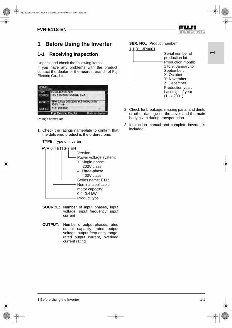
Description of change during operation
: The data changed by the or key takes effect on the inverter operation. However, press
the key to store the new data.
: Press the or key to change the data. The new data takes effect after the key is
pressed to store the data.
X: The data can be changed only while the inverter is stopped.
F: Fundamental functions
Func-tion
CodeName Setting range Min. unit
Factorysetting
Chan-ge
duringopera-
tion
RS485Data
format
Usersetting
F00 Data protection0:1:
Data change enabledData protected
1 0 X 0
F01Frequencycommand 1
0:1:2:3:4:
5:
6:
7:8:
Keypad operationVoltage input (terminal 12)Current input (terminal C1)Voltage and current inputVoltage input with polarity (terminal 12)Voltage input inverse mode operation (terminal 12)Current input inverse mode operation (terminal C1)UP/DOWN control mode 1UP/DOWN control mode 2
1 0 X 0
F02 Operation method
0:
1:2:3:
Keypad operation (direction of rotation: input at terminal block)External signal (digital input)Keypad operation (forward rotation)Keypad operation (reverse rotation)
1 2 X 0
F03 Maximum frequency 1 50 to 400 Hz 1 Hz 50 X 0
F04 Base frequency 1 25 to 400 Hz 1 Hz 50 X 0
F05Rated voltage 1(at Base frequency 1)
0V:Voltage proportional to the source voltage is output.
1 V230400
X 0 80 to 240 V (200 V class)160 to 480 V (400 V class)
F06Maximum voltage 1
(at Maximumfrequency 1)
80 to 240 V (200 V class)160 to 480 V (400 V class)
1 V 230400
X 0
F07 Acceleration time 1 0.01 to 3600 s 0.01 s 6.00
6
F08 Deceleration time 1 0.01 to 3600 s 0.01 s 6.00
6
F09 Torque boost 1
0:1:
2:
Automatic torque boostSquare reduction torquecharacteristicsProportional torque characteristics
1 0
0
3 to 31: Constant torque characteristics
MGB_E11S05.FM Page 1 Sunday, September 16, 2001 1:47 PM

5-2 5 Selecting Functions
FVR-E11S-EN
5Description of change during operation
: The data changed by the or key takes effect on the inverter operation. However, press
the key to store the new data.
: Press the or key to change the data. The new data takes effect after the key is
pressed to store the data.
X: The data can be changed only while the inverter is stopped.
Func-tion
CodeName Setting range
Min. unit Factorysetting
Chan-ge
duringopera-
tion
RS485Data
format
Usersetting
F10
Electronic thermal overload relay for motor 1
(Select)
0:1:2:
InactiveActive (for general purpose motors)Active (for forced-ventilated motors)
1 1 0
F11 (Level) 20 to 135 % of the rated inverter current 0.01 A
Fuji‘sratedmotorcurrent
6
F12(Thermal time
constant)0.5 to 10.0 min. 0.1 min 5.0
2
F13Electronic thermal overload relay
(for braking resistor)
0:1:
2:
InactiveActive (for external braking resistor DB
-2C/4C)Active (for external braking resistor TK80W : 0.1 to 2.2E11S-7DB
-4C : 0.4 to 7.5E11S-4)
1 0 X 0
F14
Restart mode after momentary power failure
0:
1:
2:
3:
Inactive (The inverter immediatelytrips upon power failure.)Inactive (The inverter trips after thepower failure is recovered.)Active (The inverter restarts at thefrequency effective at the time ofpower failure.)Active (The inverter restarts at thestarting frequency.)
1 0 X 0
F15Frequency limiter
(High) 0 to 400 Hz 1 Hz 70
0
F16 (Low) 0
0
F17Gain(For frequency setting
signal)0.0 to 200.0 % 0.1 % 100.0
2
F18 Bias frequency -400 to +400 Hz 1 Hz 0
1
F20DC brake
(Starting frequency)0.0 to 60.0 Hz 0.1 Hz 0.0
2
F21 (Braking level) 0 to 100 % 1 % 0
0
F22 (Braking time)0.0 s (Inactive)0.1 to 30.0 s
0.1 s 0.0
2
MGB_E11S05.FM Page 2 Sunday, September 16, 2001 1:47 PM

5 Selecting Functions 5-3
FVR-E11S-EN
5Description of change during operation
: The data changed by the or key takes effect on the inverter operation. However, press
the key to store the new data.
: Press the or key to change the data. The new data takes effect after the key is
pressed to store the data.
X: The data can be changed only while the inverter is stopped.
Func-tion
CodeName Setting range Min. unit
Factorysetting
Chan-ge
duringopera-
tion
RS485Data
format
Usersetting
F23Starting frequency
(Frequency)0.1 to 60.0 Hz 0.1 Hz 0.5 X 2
F24 (Holding time) 0.0 to 10.0 s 0.1 s 0.0 X 2
F25 Stop frequency 0.1 to 6.0 Hz 0.1 Hz 0.2 X 2
F26Motor sound
(Carrier frequency)0.75,1 to 15 kHz 1 kHz 15
0
F27 (Sound tone) 0 to 3 1 0
0
F29FMA and FMP terminals
(Select)
0:1:
Analog output (FMA)Pulse output (FMP)
1 0 X 0
F30FMA
(Voltage adjustment)0 to 200 % 1 % 100
0
F31 (Function)
0:
1:
2:3:4:5:6:7:8:
Output frequency 1 (before slip compensation)Output frequency 2 (after slip compensation)Output currentOutput voltageOutput torqueLoad factorInput powerPID feedback valueDC link circuit voltage
1 0
0
F33FMP
(Pulse rate)300 to 6000 p/s (Pulse count at 100 %) 1 p/s 1440
0
F34 (Voltage adjustment) 0 %, 1 to 200 % 1 % 0
0
F35 (Function) 0 to 8 (Same as F31) 1 0
0
F36 30Ry operation mode 0:1:
Excited when trippingExcited during regular operation 1 0 X 0
F40Torque limit 1
(Driving)20 to 200% 999: Inactive
1 % 180
0
F41 (Braking)0%: Automatic deceleration control20 to 200%999: Inactive
1 % 150
0
F42Torque vector control 1
0:1:
InactiveActive 1 0 X 0
MGB_E11S05.FM Page 3 Sunday, September 16, 2001 1:47 PM

5-4 5 Selecting Functions
FVR-E11S-EN
5Description of change during operation
: The data changed by the or key takes effect on the inverter operation. However, press
the key to store the new data.
: Press the or key to change the data. The new data takes effect after the key is
pressed to store the data.
X: The data can be changed only while the inverter is stopped.
E: Extension terminal functions
Func-tion
CodeName Setting range Min. unit
Factorysetting
Chan-ge
duringopera-
tion
RS485Data
format
Usersetting
E01 X1 terminal function
0:1:2:3:4:
5:
6:7:8:9:10:11:12:
13:14:15:16:17:
18:
Multistep frequency selection [SS1]Multistep frequency selection [SS2]Multistep frequency selection [SS4]Multistep frequency selection [SS8]Acceleration/deceleration time selection [RT1]3-wire operation stop command [HLD]Coast-to-stop command [BX]Alarm reset [RST]Trip command(External fault) [THR]Frequency setting 2/1 [Hz2/Hz1]Motor 2 / Motor 1 [M2/M1]DC brake command [DCBRK]Torque limiter 2/Torque limiter 1 [TL2/TL1]UP command [UP]DOWN command [DOWN]Write enable for KEYPAD [WE-KP]PID control cancel [Hz/PID]Inverse mode changeover [IVS] (terminal 12 and C1)Link enable [LE]
1
0 X 0
E02 X2 terminal function 1 X 0
E03 X3 terminal function 2 X 0
E04 X4 terminal function 6 X 0
E05 X5 terminal function 7 X 0
E10 Acceleration time 20.01 to 3600 s 0.01 s
10.0
6
E11 Deceleration time 2 10.0
6
E16Torque limiter 2
(Driving)20 to 200 %999: Inactive
1 % 180
0
E17 (Braking)0 %: Automatic deceleration control, 20 to 200 %999: Inactive
1 % 150
0
E20 Y1 terminal function
0:1:2:3:4:5:6:7:8:9:
Inverter running [RUN]Frequency equivalence [FAR]Frequency level detection [FDT]Undervoltage detection signal [LV]Torque polarity [B/D]Torque limiting [TL]Auto restarting [IPF]Overload early warning [OL]Life time alarm [LIFE]Frequency level detection 2 [FAR2]
1
0 X 0
E21 Y2 terminal function 7 X 0
MGB_E11S05.FM Page 4 Sunday, September 16, 2001 1:47 PM

5 Selecting Functions 5-5
FVR-E11S-EN
5
Description of change during operation
: The data changed by the or key takes effect on the inverter operation. However, press
the key to store the new data.
: Press the or key to change the data. The new data takes effect after the key is
pressed to store the data.
X: The data can be changed only while the inverter is stopped.
Func-tion
CodeName Setting range Min. unit
Factorysetting
Chan-ge
duringopera-
tion
RS485Data
format
Usersetting
E29Frequency level detection delay
0.01 to 10.0 s 0.01 s 0.1
6
E30FAR function signal
(Hysteresis)0.0 to 10.0 Hz 0.1 Hz 2.5
2
E31FDT function signal
(Level)0 to 400 Hz 1 Hz 50
0
E32 (Hysteresis) 0.0 to 30.0 Hz 0.1 Hz 1.0
2
E33OL function signal
(Mode select)0:1:
Electronic thermal overload relayOutput current 1 0
0
E34 (Level) 20 to 200 % of the rated inverter current 0.01 A
Fuji‘sratedmotorcurrent
6
E35 (Timer) 0.0 to 60.0 s 0.1 s 10.0
2
E40 Display coefficient A 0.00 to 200.0 0.01 0.01
6
E41 Display coefficient B 0.00 to 200.0 0.01 0.00
6
E42 LED display filter 0.0 to 5.0 s 0.1 s 0.5
2
MGB_E11S05.FM Page 5 Sunday, September 16, 2001 1:47 PM

5-6 5 Selecting Functions
FVR-E11S-EN
5
Description of change during operation
: The data changed by the or key takes effect on the inverter operation. However, press
the key to store the new data.
: Press the or key to change the data. The new data takes effect after the key is
pressed to store the data.
X: The data can be changed only while the inverter is stopped.
C: Control Functions of Frequency
Func-tion
CodeName Setting range Min. unit
Factorysetting
Chan-ge
duringopera-
tion
RS485Data
format
Usersetting
Jump frequency
0 to 400 Hz 1 HzC01 (Jump freq. 1) 0
0
C02 (Jump freq. 2) 0
0
C03 (Jump freq. 3) 0
0
C04 (Hysteresis ) 0 to 30 Hz 1 Hz 3
0
Multistep frequency setting
0.00 to 400.0 Hz 0.01 Hz
C05 (Freq. 1) 0.00
4
C06 (Freq. 2) 0.00
4
C07 (Freq. 3) 0.00
4
C08 (Freq. 4) 0.00
4
C09 (Freq. 5) 0.00
4
C10 (Freq. 6) 0.00
4
C11 (Freq. 7) 0.00
4
C12 (Freq. 8) 0.00
4
C13 (Freq. 9) 0.00
4
C14 (Freq. 10) 0.00
4
C15 (Freq. 11) 0.00
4
C16 (Freq. 12) 0.00
4
C17 (Freq. 13) 0.00
4
C18 (Freq. 14) 0.00
4
C19 (Freq. 15) 0.00
4
C21 Timer operation 0:1:
InactiveActive 1 0 X 0
C22 Stage 1 0.00 to 3600 s 0.01 s 0.00
6
C30Frequencycommand 2
0 to 8 (Same as F01) 1 2 X 0
C31Analog setting signaloffset adjustment
(Terminal 12)-5.0 to +5.0 % 0.01 % 0.0
3
C32 (Terminal C1) -5.0 to +5.0 % 0.01 % 0.0
3
C33Analog settingsignal filter
0.00 to 5.00 s 0.01 s 0.05
4
MGB_E11S05.FM Page 6 Sunday, September 16, 2001 1:47 PM
5 Selecting Functions 5-7
FVR-E11S-EN
5
Description of change during operation
: The data changed by the or key takes effect on the inverter operation. However, press
the key to store the new data.
: Press the or key to change the data. The new data takes effect after the key is
pressed to store the data.
X: The data can be changed only while the inverter is stopped.
P: Motor Parameters
Func-tion
CodeName Setting range Min. unit
Factorysetting
Chan-ge
duringopera-
tion
RS485Data
format
Usersetting
P01Number of motor 1 poles
2 to 14 2 4 X 0
P02Motor 1
(Capacity)0.01 to 5.5kW (4.0kW or less)0.01 to 11.00kW(5.5/7.5kW)
0.01 kW
NominalappliedmotorkW
X 4
P03 (Rated current) 0.00 to 99.9 A 0.01 AFuji‘s
standardrating
X 6
P04 (Tuning)0:1:2:
InactiveActive (%R, %X)Active (%R, %X, lo)
1 0 X 12
P05 (Online Tuning) 0:1:
InactiveActive 1 0 X 0
P06 (No-load current) 0.00 to 99.9 A 0.01 AFuji‘s
standardrating
X 6
P07 (%R1 setting) 0.00 to 50.00 % 0.01 %Fuji‘s
standardrating
4
P08 (%X setting) 0.00 to 50.00 % 0.01 %Fuji‘s
standardrating
4
P09(Slip compensation
control 1)0.00 to 15.00 Hz 0.01 Hz 0.00
4
P10(Slip compensation response time 1)
0.01 to 10.00 s 0.01 s 0.50
4
MGB_E11S05.FM Page 7 Sunday, September 16, 2001 1:47 PM

5-8 5 Selecting Functions
FVR-E11S-EN
5
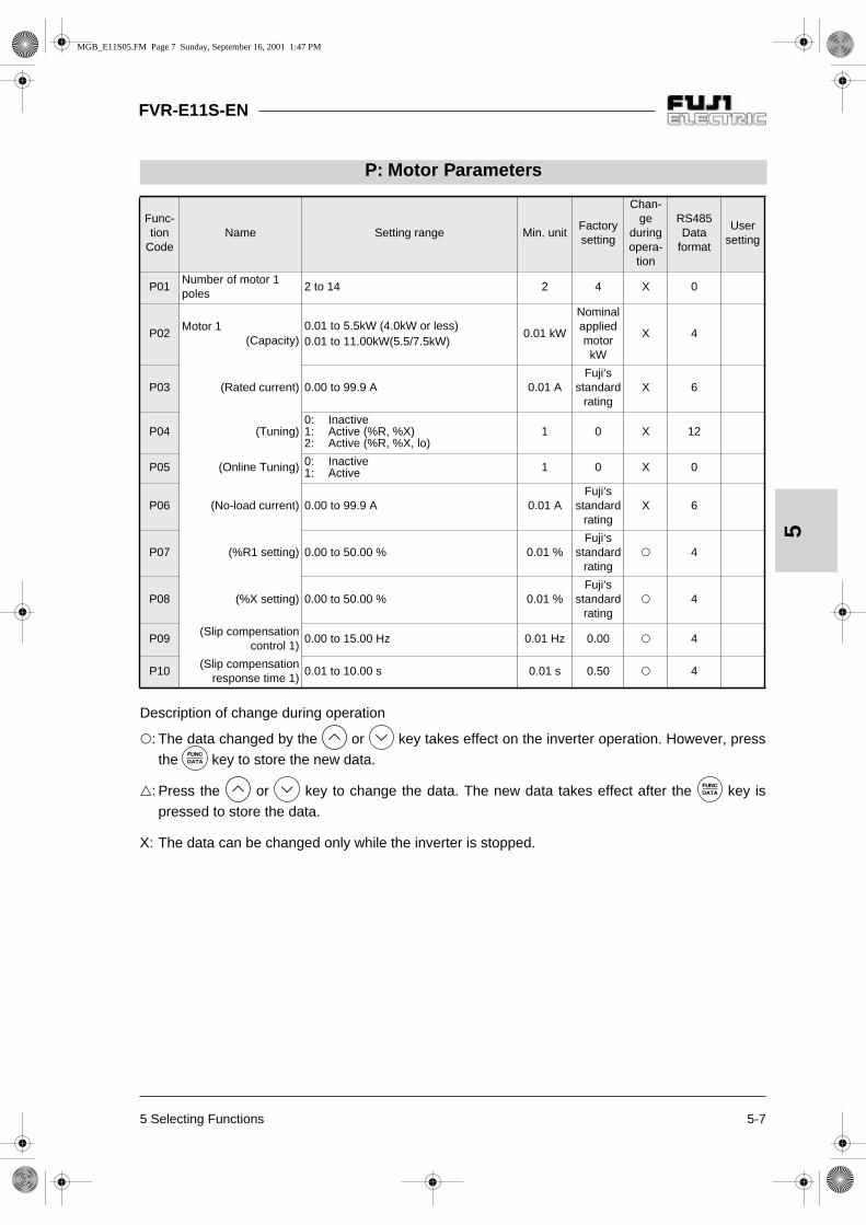
H: High Performance Functions
Func-tion
CodeName Setting range Min. unit
Factorysetting
Chan-ge
duringopera-
tion
RS485Data
format
Usersetting
H01 Total operation time Monitor only 10h 0 - 0
H02 Trip history Monitor only - ---- -
H03Data initializing(Data reset)
0:1:
Manual set valueReturn to factory set value 1 0 X 0
H04 Auto-reset (Times) 0: Inactive 1 to 10 times 1 time 0
0
H05 (Reset interval) 2 to 20s 1s 5
0
H06 Fan stop operation 0:1:
InactiveActive 1 0
0
H07ACC/DEC pattern(Mode select).
0:1:
2:
3:
Linear acceleration/decelerationS-curve acceleration/deceleration (weak)S-curve acceleration/deceleration (strong)Non-linear
1 0 X 0
H09Start mode (Rotating motor
pickup mode)
0:1:
2:
InactiveActive (only when Auto-restart after momentary power failure mode)Active(All start mode)
1 1 X 0
H10Energy-savingoperation
0:1:
InactiveActive 1 0
0
H11 Dec mode 0:1:
NormalCoast-to-stop 1 0
0
H12Instantaneousovercurrent limiting
0:1:
InactiveActive 1 1 X 0
H13Auto-restart
(Restart time)0.1 to 5.0s
0.1s 0.1 X 2
H14 (Frequency fall rate) 0.00 to 100.0Hz/s 0.01Hz/s 10.00
4
H20PID control
(Mode select)
0:1:2:
InactiveForward operationReverse operation
1 0 X 0
H21 (Feedback signal)
0:1:2:3:
Terminal 12 (0 to +10 Vdc) inputTerminal C1 (4 to 20 mA) inputTerminal 12 (+10 to 0 Vdc) inputTerminal C1 (20 to 4 mA) input
1 1 X 0
H22 P (Gain) 0.01 to 10.00 times (1 to 1000%) 0.01 time 0.10
4
H23 I (Integral time) 0.0: Inactive0.1 to 3600s 0.1s 0.0
2
H24 D (Differential time) 0.00: Inactive0.01 to 10.0s 0.01s 0.00
4
H25 (Feedback filter) 0.0 to 60.0s 0.1s 0.5
2
H26PTC thermistor
(Mode select)0:1:
InactiveActive 1 0
0
H27 (Level) 0.00 to 5.00V 0.01V 1.60
4
H28 Droop operation -9.9 to 0.0Hz 0.1Hz 0.0
3
MGB_E11S05.FM Page 8 Sunday, September 16, 2001 1:47 PM
5 Selecting Functions 5-9
FVR-E11S-EN
5
Description of change during operation
: The data changed by the or key takes effect on the inverter operation. However, press
the key to store the new data.
: Press the or key to change the data. The new data takes effect after the key is
pressed to store the data.
X: The data can be changed only while the inverter is stopped.
Func-tion
CodeName Setting range Min. unit
Factorysetting
Chan-ge
duringopera-
tion
RS485Data
format
Usersetting
H30Serial link
(Function select)0:1:2:3:
Monitor Frequency Operationsetting command
x x x x
1 0 0
H31RS485
(Address)1 to 31
1 1 X 0
H32(Mode select on no
response error)
0:1:2:
3:
Immediate Er8Er8 after interval set by timerRetry in interval set by timer (Er8 after failure to restore)Continuation of operation
1 0 0
H33 (Timer) 0.0 to 60.0s 0.1s 2.0 2
H34 (Baud rate)
0:1:2:3:4:
19200[bit/s]9600480024001200
1 1 0
H35 (Data length) 0:1:
8bit7bit 1 0 0
H36 (Parity check)0:1:2:
NoneEven parityOdd parity
1 0 0
H37 (Stop bits) 0:1:
2bits1bit 1 0 0
H38(No response error
detection time)0: Not detected1 to 60s 1s 0 0
H39 (Response interval) 0.00 to 1.00s 0.01s 0.01 4
H40Maximum temperature of heat sink
Monitor only degree C - - 0
H41Maximum effective current
Monitor only A - - 6
H42Main circuit capacitor life
Monitor only 0.1% - - 0
H43Cooling fan operation time
Monitor only 10h - - 0
H44 Inverter ROM version Monitor only - - - 0
H45Keypad panel ROM version
Monitor only - - - 0
H46 Option ROM version Monitor only - - - 0
MGB_E11S05.FM Page 9 Sunday, September 16, 2001 1:47 PM

5-10 5 Selecting Functions
FVR-E11S-EN
5
Description of change during operation
: The data changed by the or key takes effect on the inverter operation. However, press
the key to store the new data.
: Press the or key to change the data. The new data takes effect after the key is
pressed to store the data.
X: The data can be changed only while the inverter is stopped.
A: Alternative motor parameters
Func-tion
CodeName Setting range Min. unit
Factorysetting
Chan-ge
duringopera-
tion
RS485Data
format
Usersetting
A01 Maximum frequency 2 50 to 400Hz 1 Hz 50 X 0
A02 Base frequency 2 25 to 400Hz 1 Hz 50 X 0
A03Rated voltage 2 (at base frequency 2)
0V, 80 to 240V(200V class)0V,160 to 480V(400V class)
1 V230400
X 0
A04Maximum voltage 2(at maximum frequency 2)
80 to 240V (200V class)160 to 480V(400V class)
1 V230400
X 0
A05 Torque boost 2 0, 1, 2, 3 to 31 1 0 0
A06Electronic thermal overload relay for motor 2 (Select)
0:1:2:
InactiveActive (for general purpose motors)Active (for inverter motors)
1 1 0
A07 (level) 20 to 135% of the rated inverter current 0.01 A
Fuji’sratedmotorcurrent
6
A08(Thermal time
constant)0.5 to 10 min. 0.1 min 5.0 2
A09Torque vector control 2
0:1:
InactiveActive 1 0 X 0
A10Number of motor 2 poles
2 to 14 2 4 X 0
MGB_E11S05.FM Page 10 Sunday, September 16, 2001 1:47 PM

5 Selecting Functions 5-11
FVR-E11S-EN
5
Description of change during operation
: The data changed by the or key takes effect on the inverter operation. However, press
the key to store the new data.
: Press the or key to change the data. The new data takes effect after the key is
pressed to store the data.
X: The data can be changed only while the inverter is stopped.
Func-tion
CodeName Setting range Min. unit
Factorysetting
Chan-ge
duringopera-
tion
RS485Data
format
Usersetting
A11Motor 2
(Capacity)0.01 to 5.5kW (4.0kW or less)0.01 to 11.00kW(5.5/7.5kW)
0.01 kW
NominalappliedmotorkW
X 4
A12 (Rated current) 0.00 to 99.9 A 0.01 AFuji‘s
standardrating
X 6
A13 (Tuning)0:1:2:
InactiveActive (%R, %X)Active (%R, %X, lo)
1 0 X 12
A14 (Online Tuning) 0:1:
InactiveActive 1 0 X 0
A15 (No-load current) 0.00 to 99.9 A 0.01 AFuji‘s
standardrating
X 6
A16 (%R1 setting) 0.00 to 50.00 % 0.01 %Fuji‘s
standardrating
4
A17 (%X setting) 0.00 to 50.00 % 0.01 %Fuji‘s
standardrating
4
A18(Slip compensation
control 2)0.00 to 15.00 Hz 0.01 Hz 0.00 4
A19(Slip compensation response time 2)
0.01 to 10.00 s 0.01 s 0.50 4
O: Optional functions
Func-tion
CodeName Setting range Min. unit
Factorysetting
Chan-ge
duringopera-
tion
RS485Data
format
Usersetting
o00 Optional selection
0:1:
Option inactiveOption active(Set 0 when optional card is not used.)
- 0 0
MGB_E11S05.FM Page 11 Sunday, September 16, 2001 1:47 PM

FVR-E11S-EN
5-12 5 Selecting Functions
5
5-2 Detail Description of Each Function
Data protection The setting data can be protected against
inadvertent operation at the keypad panel.
Set value 0 : Data change enabled1 : Data protected
[Setting method]0 to 1: Press the and keys simulta-
neously.1 to 0: Press the and keys simulta-
neously.
Frequency command 1 The frequency setting method can be
selected.
0: The frequency is set by the operation of
and keys1: The frequency is set by the voltage input
(at terminal 12) (0 to +10 Vdc)2: The frequency is set by the current input
(at terminal C1) (4 to 20 mAdc).3: The frequency is set by the voltage input and
current input (terminal 12 and terminal C1)((-10 to +10 Vdc) + (4 to 20 mAdc)). Inputs atterminals 12 and C1 are added to determinethe frequency.
4: The frequency is set by the voltage input with polarity (at terminal 12) (-10 to +10 Vdc).In the case of input with polarity, operation ata direction opposite to the operation com-mand is possible
5: The frequency is set by voltage input inversemode operation (at terminal 12) (+10 to 0 Vdc).
6: The frequency is set by current input inversemode operation (at terminal C1) (20 to 4 mAdc)
7: UP/DOWN control mode 1The frequency is set by terminal UP, terminalDOWN. (initial value = 0) )8: UP/DOWN control mode 2The frequency is set by terminal UP, terminalDOWN (initial value = last value during previousoperation).Refer to the description of the E01 to E05functions for details.
Description of forward and reverse operation
F: Fundamental functions
F00
F01
Normal mode operation(setting: 1, 3, 4)
Frequency setting
Maximum frequency
Setting: 1, 3
Setting: 4- Maximum frequency
Analog input terminal [12], [V2]
Inverse mode operation(setting: 5)
Normal mode ope-ration (setting: 2)
Inverse mode ope-ration (setting: 6)
Analog input terminal [C1]
Maximum frequency
Frequency setting
MGB_E11S05.FM Page 12 Sunday, September 16, 2001 1:47 PM

5 Selecting Functions 5-13
FVR-E11S-EN
5
Frequency setting block diagram
Frequency setting
Keypad panel frequency setting
Fre
quen
cy s
ettin
g si
gnal
Analog input filter
Forward / reverse
operation
Negativepolarity
prevention
Gain Biasfrequency
Feedbackselection
Feedbackfilter
PID control
OperationselectionProportion
Integration
Differentiation
Limit signal
Maximumfrequency
Upper limit frequency
Limiterprocess
Fre-quencysetting
Lower limit frequency
Multistep frequency1 to 15
Link function frequency
setting
Multistepfrequency
changeover
UP/DOWNcontrol
Change-overcommand
Reverseoperation
Jumpfrequency
Reverseoperation
MGB_E11S05.FM Page 13 Sunday, September 16, 2001 1:47 PM

5-14 5 Selecting Functions
FVR-E11S-EN
5
Operation method The operation input method is set.
(Note: This function can be changed onlywhen the FWD and REV terminals are open.)
0: The motor starts or stops upon keypad
operation ( or ) key. The direction of rotation is determined bythe FWD and REV terminals on the controlterminal block as follows. FWD-P24 short-circuited:Forward rotationREV-P24 short-circuited:Reverse rotation
. The motor does not start if both the FWDand REV terminals are connected with theP24 terminal or both of them are open.
1: External signal (digital input) The motor starts or stops upon the state of the FWD and REV terminals on the control terminal block.FWD-P24 short-circuited:Forward rotationREV-P24 short-circuited:Reverse rotation
. The motor does not start if both the FWD and REV terminals are connected with the P24 terminal or both of them are open
2: Keypad operation (forward rotation only)The motor runs in the forward direction
when the key is pressed and
it decelerates to stop when the key is pressed.
3: Keypad operation (reverse rotation only)The motor runs in the reverse direction
when the key is pressed and
it decelerates to stop when the keyis pressed.
Maximum frequency 1 This is the maximum frequency which is out-
put by the inverter of motor 1.
Setting range: 50 to 400 Hz
If a value larger than the rating of the driven unitis set, the motor or machine may be broken. Seta value suitable for the driven unit.
Base frequency 1 This is the maximum output frequency in the
constant torque zone of motor 1, that is, theoutput frequency at the rated output voltage.Set the rating of the motor.
Setting range: 25 to 400 Hz
Note: If the setting of base frequency 1 islarger than the setting of maximumfrequency 1, the output frequency islimited by the maximum frequencyand the output voltage does not riseto the rated voltage.
F02 F03
F04
F06 Maxi-mum output voltage 1
Outputvoltage
Constanttorquezone
Output frequency
F04 Basefrequency 1
F03 Maximum output
frequency 1
F05 Ratedvoltage 1
MGB_E11S05.FM Page 14 Sunday, September 16, 2001 1:47 PM
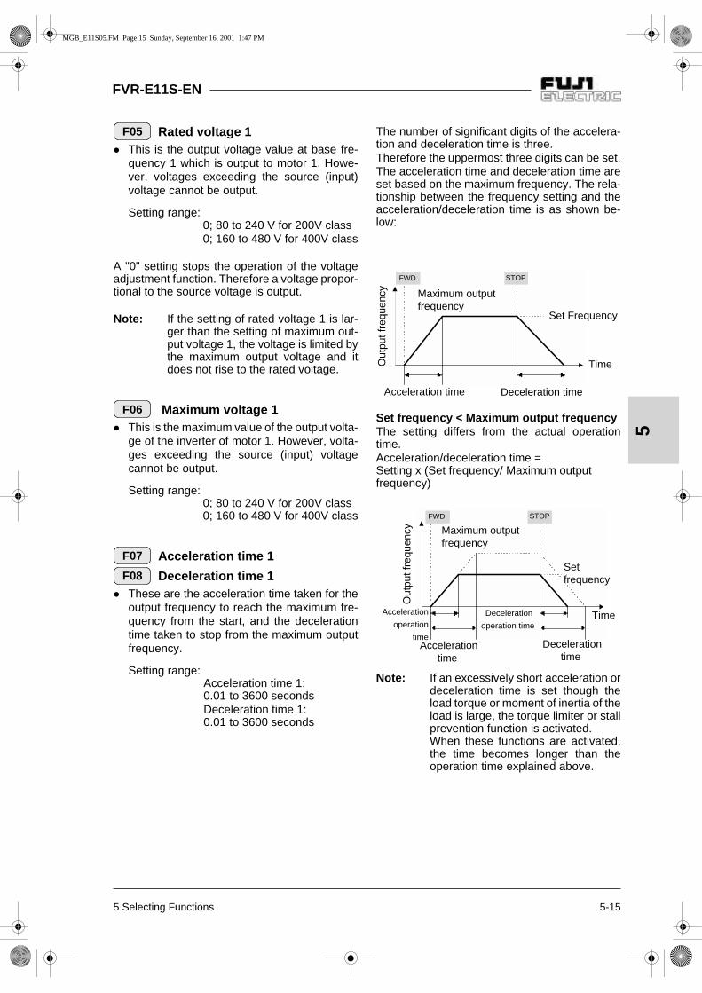
5 Selecting Functions 5-15
FVR-E11S-EN
5
Rated voltage 1 This is the output voltage value at base fre-
quency 1 which is output to motor 1. Howe-ver, voltages exceeding the source (input)voltage cannot be output.
Setting range: 0; 80 to 240 V for 200V class0; 160 to 480 V for 400V class
A "0" setting stops the operation of the voltageadjustment function. Therefore a voltage propor-tional to the source voltage is output.
Note: If the setting of rated voltage 1 is lar-ger than the setting of maximum out-put voltage 1, the voltage is limited bythe maximum output voltage and itdoes not rise to the rated voltage.
Maximum voltage 1 This is the maximum value of the output volta-
ge of the inverter of motor 1. However, volta-ges exceeding the source (input) voltagecannot be output.
Setting range: 0; 80 to 240 V for 200V class0; 160 to 480 V for 400V class
Acceleration time 1
Deceleration time 1 These are the acceleration time taken for the
output frequency to reach the maximum fre-quency from the start, and the decelerationtime taken to stop from the maximum outputfrequency.
Setting range: Acceleration time 1:0.01 to 3600 secondsDeceleration time 1:0.01 to 3600 seconds
The number of significant digits of the accelera-tion and deceleration time is three.Therefore the uppermost three digits can be set.The acceleration time and deceleration time areset based on the maximum frequency. The rela-tionship between the frequency setting and theacceleration/deceleration time is as shown be-low:
Set frequency < Maximum output frequencyThe setting differs from the actual operationtime.Acceleration/deceleration time = Setting x (Set frequency/ Maximum output frequency)
Note: If an excessively short acceleration ordeceleration time is set though theload torque or moment of inertia of theload is large, the torque limiter or stallprevention function is activated. When these functions are activated,the time becomes longer than theoperation time explained above.
F05
F06
F07
F08
FWD STOP
Maximum output frequency
Set Frequency
Time
Deceleration time Acceleration timeO
utpu
t fre
quen
cy
FWD STOP
Maximum output frequency
Setfrequency
Time
Deceleration time
Acceleration time
Out
put f
requ
ency
Deceleration
operation time
Acceleration
operation
time
MGB_E11S05.FM Page 15 Sunday, September 16, 2001 1:47 PM

FVR-E11S-EN
5-16 5 Selecting Functions
5
Torque boost 1 This function is for motor 1.
The following options can be selected:– Selection of load characteristics such as au-
tomatic torque boost, square reduction torqueload, proportional torque load and constanttorque load.
– Correction of magnetic flux shortage of motorin accordance with the voltage drop in low fre-quency zone, and torque boost during lowspeed operation (boosting of V/f characteri-stics).
Torque characteristics
Constant torque characteristics
Note: When the torque boost value is ex-cessively large, the motor is excessi-vely excited in the low speed zone atall types of characteristics. If operati-on continues in such a state, the mo-tor may be overheated. Set a valueaccording to the characteristics of thedriven motor.
Settingrange
Description of selection
0
Automatic torque boost characteristics where the torque boost value of theconstant torque load is automatically adjusted (refer to function code P04 "Motor 1 (“(Tuning)").
1Square reduction torque characteri-stics for fan and pump loads.
2
Proportional torque characteristics for intermediate load between the square reduction torque and torque characteri-stics.
3 to 31 Constant torque characteristics.
F09
Rated voltage 1
Basefrequency 1
Output voltage V
Output frequency f
Square reduction torque characteristicsProportional torque characteristics
Rated voltage 1
Base frequency 1
Output voltage V
Output frequency f
MGB_E11S05.FM Page 16 Sunday, September 16, 2001 1:47 PM

5 Selecting Functions 5-17
FVR-E11S-EN
5
Electronic thermal overload relay 1 (Select)
Electronic thermal overload relay 1 (Level)
Electronic thermal overload relay 1 (Thermal time constant)
The electronic thermal overload relay watchesthe output frequency, output current and opera-tion time of the inverter to prevent the motor fromoverheat. The protective function becomes acti-ve when 150% of the set amperage flows for thetime set at F12 (thermal time constant).
Selection between active and inactive opera-tion of the electronic thermal overload relayand selection of the target motor are made.When the general purpose motor is selected,the operation level is low at low revolutionspeeds according to the cooling characteri-stics of the motor.
Setting: 0: Inactive1: Active
(for general purpose motor)2: Active
(for forced-ventilated motor)
The operation level of the electronic thermaloverload relay is set in amperage. Enter thevalue 1.0 to 1.1 times rated current of the mo-tor.
The setting range is 20 to 135% of the ratedinverter current.
Graph of relationship between operation level current and output frequency
Set the time since 150% of the operation levelcurrent flows continuously until the electronicthermal overload relay functions.
Setting range: 0.5 to 10.0 min (minimum unit 0.1 minute).
F10
F11
F12
F10
F11
fe x 0.33
When F10 = 2
(When F10 = 1)
Ope
ratio
n le
vel c
urre
nt in
[%]
fb: Base frequency
Output frequency f0 [Hz]
F12
Ope
ratio
n tim
e [m
in]
Set by F12
((Output current)/(Operation level current)) x 100 [%]
Typical current - operation time characteristics
MGB_E11S05.FM Page 17 Sunday, September 16, 2001 1:47 PM

FVR-E11S-EN
5-18 5 Selecting Functions
5
Electronic thermal overload relay (for External braking resistor)
This function controls the operation frequencyof the braking resistor and the continuousoperation hours to prevent the braking resi-stor from being overheated.
Restart mode after momentary power failure
Select the operation to be taken by the inver-ter upon momentary power failure.
You can select between protective operation(alarm output, alarm display, and inverteroutput shutoff) upon detection of power failureto be taken against an undervoltage andrestart after momentary power failure wherethe coasting motor is not stopped but auto-matically restarted after the source voltage isrecovered.
Setting range: 0 to 3.
(Refer to the table below for details of thefunction.)
Set-ting
Name of function Operation upon power failure Operation upon power recovery
0
Inactive after momentary power failure (The inverter trips immediately.).
Upon detection of an undervoltage, a protective function is activated to stop the output.
The inverter does not restart.
The inverter restarts after the protective function is reset and an operation command is input.
1
Inactive after momentary power failure (The inverter trips after the power is recovered.).
Upon detection of an undervoltage, no protective function is activated but the output is stopped.
A protective function is acti-vated; the inver-ter does not restart.
2
Restart after momentary power failure (The inverter restarts at the fre-quency effective at the time of power failure.).
Upon detection of an undervoltage, no protective function is activated but the output is stopped.
The inverter automatically restarts at the output frequency effective at the time of power failure.
3
Restart after momentary power failure (The inverter restarts at the star-ting frequency; for low inertia loads.).
Upon detection of an undervoltage, no protective function is activated but the output is stopped.
The inverter automatically restarts at the starting frequency set at F23.
F13
Setting 0: Inactive 1: Active (For external braking resistor
DB -2C/4C)2: Active (For external braking resistor
TK80W120Ω) [0.1 to 2.2E11S-7] Active (For external braking resistor DB -4C) [0.4 to 7.5E11S-4]
F14
MGB_E11S05.FM Page 18 Sunday, September 16, 2001 1:47 PM

5 Selecting Functions 5-19
FVR-E11S-EN
5
Note: The chain line indicates the motor speed.
Function codes used for the restart after momen-tary power failure include H13 and H14. Refer tothe description of these codes, too. As well, a rotating motor pickup function can beselected as a starting method after a momentarypower failure. (Refer to function code H09 for de-tails of setting.)When the pickup function is used, the speed ofthe coasting motor is detected and the motor isstarted without a shock.
Because a speed detection time is necessary ifthe pickup function is made effective, the pickupfunction should be made ineffective and restartshould be made at the frequency effective beforethe power failure in a system with a large inertiato restore the original frequency, to make themost of the small decrease in the speed of thecoasting motor.The effective range of the pickup function is 5 to120 Hz. If the detected speed is out of the effec-tive range, the inverter restarts according to theregular function of restart after momentary powerfailure.
Setting: 0
Main circuit DC voltage
Under-voltage
Power failure Powerrestoration
TimeOutputfrequency
Protectivefunction 30 relay Active
Setting: 1
Main circuit DC voltage
Undervoltage
Time
Outputfrequency
Protectivefunction 30 relay Active
Power failure Powerrestoration
Setting: 2
Main circuit DC voltage
Undervoltage
Outputfrequency
(Motor speed)
Protective function30 relay
Output terminal(Y1-Y2 terminals);
IPF signalON
H13: Wait time
Accele-ration
Synchroni-zation
Setting: 3
Main circuit DC voltage
Undervoltage
Outputfrequency
(Motor speed)
Protective function 30relay
Output terminal(Y1-Y2 terminals);
IPF signal
H13: Wait time
MGB_E11S05.FM Page 19 Sunday, September 16, 2001 1:47 PM

FVR-E11S-EN
5-20 5 Selecting Functions
5
Frequency limiter (High)
Frequency limiter (Low) Set the upper and lower limits of the frequency
setting.
Setting range: 0 to 400 Hz
- The starting frequency is output when the in-verter starts operation, and the stopping fre-quency is output when it stops operation
- (Low limit) > (High limit) ... Priority is given tothe High limit value.
Gain (Frequency setting signal) Set the ratio of the frequency setting in relati-
on to the analog input.
The operation is as shown in the figure below.
Bias frequency This function obtains the frequency setting
from addition of the frequency setting in rela-tion to the analog input and a bias frequency.
The operation is as shown in the figure below.However, if the bias frequency is larger (smaller)than the maximum frequency (- maximum fre-quency), the limit is set at the maximum outputfrequency (- maximum output frequency).
DC brake (Starting frequency)
DC brake (Braking level)
DC brake (Braking time)
Starting frequency: Set the frequency atwhich the DC brake starts operation duringdeceleration and stop.
Setting range: 0.0 to 60.0 Hz
F15
F16
+ Maximum frequency
Lower limit value
Frequencyset
Upper limit value
Upper limit value
Frequency setting
Lower limit value
- Maximum frequency
F17
+ Maximumfrequency
Analog input
- Maximumfrequency
Set frequencyvalue
+ 10Vterminal 1220 mAterminal C1
F18
+ Maximumfrequency
Analog input+10 V terminal 12
20 mA terminal C1
Bias frequency(when negative)
- Maximumfrequency
Set frequency value
Bias frequency (when positive)
F20
F21
F22
F20
MGB_E11S05.FM Page 20 Sunday, September 16, 2001 1:47 PM

5 Selecting Functions 5-21
FVR-E11S-EN
5
Braking level: Set the output current level du-ring DC braking. The level can be set in anincrement of 1% of the rated inverter outputcurrent.
Setting range: 0 to 100%
Actual minimum level is fixed to 5% even if this function set from 1 to 5%for 5.5/7.5E11S-4EN
Braking time: Set the operation time of DCbraking.
Setting range 0.0: Inactive0.1 bis 30.0 seconds
Starting frequency (Frequency)
Starting frequency (Holding time)
Stop frequencyThe starting frequency can be set to insure thetorque during start of operation. Holding time forat the starting frequency before acceleration canbe set to wait for establishment of the magneticflux of the motor during start of operation.
Frequency: Set the starting frequency.
Setting range: 0.1 to 60.0 Hz
Holding time: Set the time for continuing thestarting frequency during start of operation.
Setting range: 0.0 to 10.0 seconds
- The Holding time is not placed duringchangeover between forward and reverserotation.
- The Holding time is not included in theacceleration time.
- The function is effective even when C21Timer operation is selected; the time isincluded in the timer value.
Set the stop frequency.
Setting range: 0.1 to 6.0 Hz
When the starting frequency is smaller than thestop frequency and the frequency setting issmaller than the stop frequency, operation doesnot start.
F21
F22
CAUTIONThe brake function of the inverter doesnot insure the function of a mechanicallatch.Injuries could occur!
F23
F24
F25
F23
F24
F25
Starting frequencyStopping frequency
Output frequency
Continuationtime
Forward rotation
Time
MGB_E11S05.FM Page 21 Sunday, September 16, 2001 1:47 PM

FVR-E11S-EN
5-22 5 Selecting Functions
5
Motor sound (Carrier frequency) This function adjusts the carrier frequency.
After adjustment, reduction of the motor noi-se, avoidance of resonance with the mecha-nical system, reduction of leakage currentfrom the output circuit wiring, reduction of in-verter noise and other effects can be obtai-ned.
Setting range: 0.75 to 15 (0.75 to 15 kHz)
- A smaller setting causes a worse outputcurrent waveform (with much harmoniccomponent) to cause an increase in themotor loss, resulting in a slightly higher motortemperature.
For example, when 0.75 kHz is set, reducethe motor torque by about 15%. When a largevalue is set, the inverter loss increases,raising the inverter temperature.
Motor sound (Sound tone) The sound tone of the motor noise can be
changed when the carrier frequency is 7 kHzor lower. Use the function according topreference.
Setting range: 0, 1, 2, 3
FMA and FMP terminals (Select) Select the operation method of the FM
terminal.
0: Analog output (FMA function)1: Pulse output (FMP function)
FMA (Voltage adjust)
FMA (Function)The output frequency, output current and othermonitor data can be output to the FM terminal ina DC voltage. The amplitude can be adjusted.Note: To use the FM terminal for analog
outputs, set F29 at "0" and set SW1on the control board to FMA.
Adjust the voltage corresponding to 100 [%]of the monitoring amount of the monitoringitem selected at F31 in a range from 0 to 200[%] (in an increment of 1 [%]).
Setting range: 0 to 200 [%]
Carrier frequency Lower Higher
Motor noise Larger to Smaller
Output current waveform
Worse to Better
Leakage current Less to More
Noise generation Less to More
F26
F27
F29
F30
F31
F30
10V or aboveF
MA
term
inal
out
put
volta
ge
MGB_E11S05.FM Page 22 Sunday, September 16, 2001 1:47 PM

5 Selecting Functions 5-23
FVR-E11S-EN
5
Select the monitoring item to be output at theFM terminal.
FMP (Pulse rate)
FMP (Voltage adjust)
FMP (Function)The output frequency, output current and othermonitor data can be output at the FM terminal inpulse voltages. The average voltage can be con-nected to an analog meter.
To select the pulse output and connect a digitalcounter or the like, set the F33 pulse rate to adesired value and set the F34 voltage to 0%.
To select the average voltage and connect ananalog meter, set the F34 voltage to determinethe average voltage; the F33 pulse rate is fixedat 2670 [p/s].
Note: To use the FM terminal for the pulseoutput, set F29 to "1" and set SW1 onthe control board to the FMP side.
Set the pulse frequency corresponding to 100[%] of the monitoring amount of the monito-ring item selected by F35 in a range from 300to 6000 [p/s].
Setting range: 300 to 6000 [p/s]
Pulse period [p/s] = 1/TDuty [%] = T1/T x 100Average voltage [V] = 15.6 x T1/T
Set the average voltage of the pulse output atthe FM terminal.
Setting range: 0 to 200 [%]However, if "0" is set, the pulse frequency va-ries according to the monitoring amount of themonitoring item selected at F35 (with the ma-ximum value being the F33 setting).
If a value between 1 and 200 is set, the pulsefrequency is fixed at 2670 [p/s].
The average voltage corresponding to 100 [%]of the monitoring amount of the monitoringitem selected at F35 is adjusted in a rangebetween 1 and 200 [%] (in an increment of 1 [%]).(The duty of the pulse changes.)
Note: FMP has approx. 0.2V offset voltageeven if FMP outputs zero value.
Select the monitoring item to be output at theFM terminal.
The options to be selected are the same asF31.
Set-ting
Target of monitoringDefinition of 100% of monitoring amount
0Output frequency 1 (before slip compensation)
Maximum output frequency
1Output frequency 2 (after slip compensation)
Maximum output frequency
2 Output current2 times rated inverter output current
3 Output voltage250V (200V class) ,500V (400V class)
4 Output torque2 times rated motor torque
5 Load factor 2 times rated motor load
6 Input power2 times rated inverter output
7 PID feedback value 100% feedback value
8DC link circuit voltage
500V (200V class)1000V (400V class)
F31
F33
F34
F35
F33
Approx. 15.6 [V]
Pulse period
F34
F35
MGB_E11S05.FM Page 23 Sunday, September 16, 2001 1:47 PM

FVR-E11S-EN
5-24 5 Selecting Functions
5
30Ry operation mode Select whether the alarm output relay (30Ry)
of the inverter is activated (excited) duringnormal operation or during a trip.
Note: Because the contact between 30Aand 30C is on after the inverter is tur-ned on (after about 1 second sincethe power is turned on) when the set-ting is "1", care must be taken to thesequence design.
Torque limiter 1 (Driving)
Torque limiter 1 (Braking) The torque limiting operation calculates the
motor torque from the output voltage, current,resistance of the primary winding of the motorand other data to control the frequency sothat the calculated value does not exceed thecontrol value. This operation insures inverteroperation without tripping upon abrupt chan-ges in the load torque while the limit value ismaintained.
Select the limit values of the driving torqueand braking torque.
The acceleration/deceleration operation timeduring activation of this function becomeslonger than the set acceleration/decelerationtime. When the driving torque is limited duringconstant speed operation, the frequency is lo-wered to reduce the load torque. (When thebraking torque is limited, the contrary oc-curs.).
Setting range: 20 to 200, 999%
Set "999" to inactivate the torque limiter.
Set only the braking torque to "0" toautomatically avoid OU tripping caused bypower regeneration
Torque vector control 1 The torque vector control calculates the tor-
que suitable for the load to make the most ofthe motor torque, and controls the voltageand current vectors to optimum ones accor-ding to the calculated value.
Set-ting
Description of operation
0
During normal operation 30A - 30C:OFF30B - 30C:ON
Upon a trip 30A - 30C:ON 30B - 30C:OFF
1
During normal operation 30A - 30C:ON30B - 30C:OFF
Upon a trip 30A - 30C:OFF 30B - 30C:ON
F36
F40
F41
Setting State of operation
0 Inactive
1 Active
WARNINGIf the torque limiter has been selected,the inverter may operate at an accele-ration/deceleration time or speed diffe-rent from the set ones. Design themachine so that safety is ensuredeven in such cases. Otherwise an accident could occur.
F42
MGB_E11S05.FM Page 24 Sunday, September 16, 2001 1:47 PM
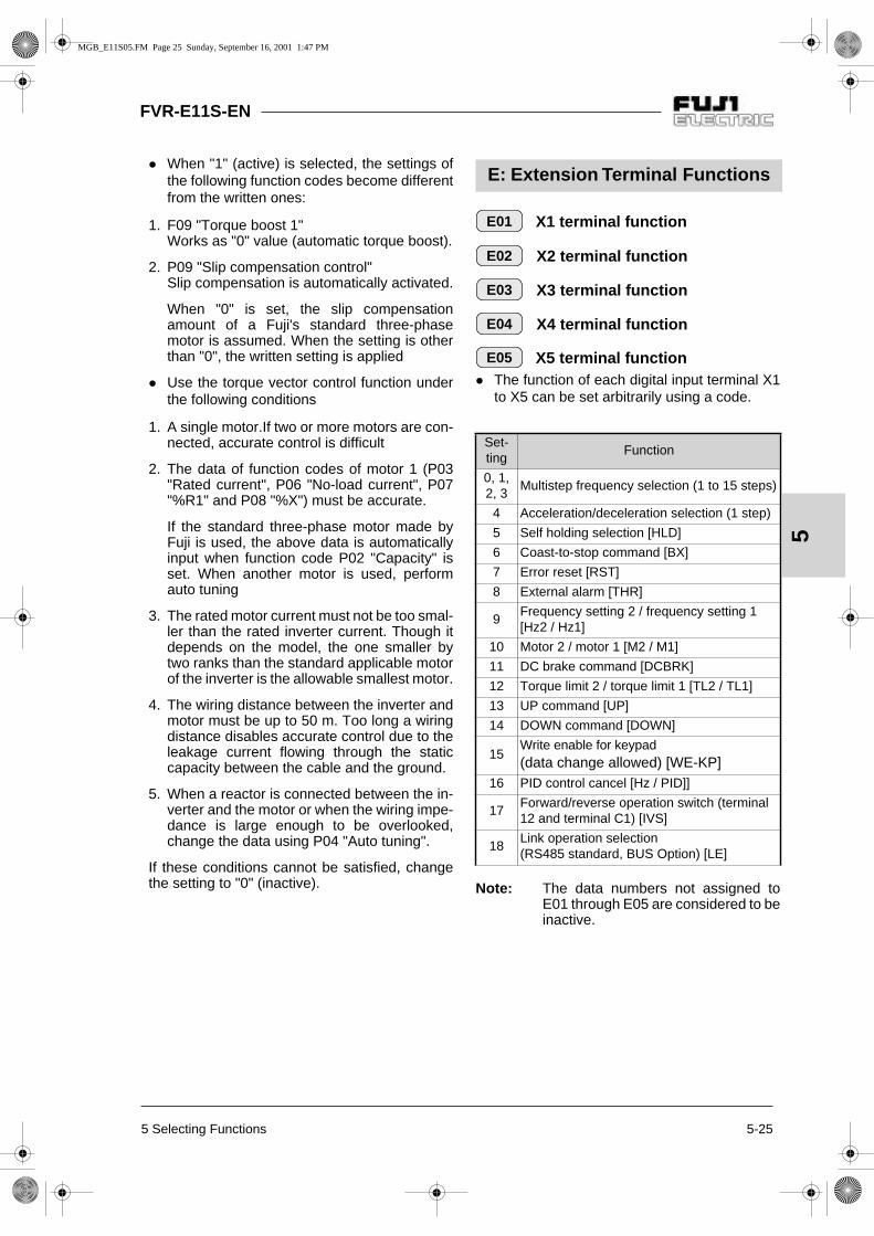
5 Selecting Functions 5-25
FVR-E11S-EN
5
When "1" (active) is selected, the settings ofthe following function codes become differentfrom the written ones:
1. F09 "Torque boost 1"Works as "0" value (automatic torque boost).
2. P09 "Slip compensation control"Slip compensation is automatically activated.
When "0" is set, the slip compensationamount of a Fuji's standard three-phasemotor is assumed. When the setting is otherthan "0", the written setting is applied
Use the torque vector control function underthe following conditions
1. A single motor.If two or more motors are con-nected, accurate control is difficult
2. The data of function codes of motor 1 (P03"Rated current", P06 "No-load current", P07"%R1" and P08 "%X") must be accurate.
If the standard three-phase motor made byFuji is used, the above data is automaticallyinput when function code P02 "Capacity" isset. When another motor is used, performauto tuning
3. The rated motor current must not be too smal-ler than the rated inverter current. Though itdepends on the model, the one smaller bytwo ranks than the standard applicable motorof the inverter is the allowable smallest motor.
4. The wiring distance between the inverter andmotor must be up to 50 m. Too long a wiringdistance disables accurate control due to theleakage current flowing through the staticcapacity between the cable and the ground.
5. When a reactor is connected between the in-verter and the motor or when the wiring impe-dance is large enough to be overlooked,change the data using P04 "Auto tuning".
If these conditions cannot be satisfied, changethe setting to "0" (inactive).
X1 terminal function
X2 terminal function
X3 terminal function
X4 terminal function
X5 terminal function The function of each digital input terminal X1
to X5 can be set arbitrarily using a code.
Note: The data numbers not assigned toE01 through E05 are considered to beinactive.
Set-ting
Function
0, 1, 2, 3
Multistep frequency selection (1 to 15 steps)
4 Acceleration/deceleration selection (1 step)
5 Self holding selection [HLD]
6 Coast-to-stop command [BX]
7 Error reset [RST]
8 External alarm [THR]
9Frequency setting 2 / frequency setting 1 [Hz2 / Hz1]
10 Motor 2 / motor 1 [M2 / M1]
11 DC brake command [DCBRK]
12 Torque limit 2 / torque limit 1 [TL2 / TL1]
13 UP command [UP]
14 DOWN command [DOWN]
15Write enable for keypad (data change allowed) [WE-KP]
16 PID control cancel [Hz / PID]]
17Forward/reverse operation switch (terminal 12 and terminal C1) [IVS]
18Link operation selection (RS485 standard, BUS Option) [LE]
E: Extension Terminal Functions
E01
E02
E03
E04
E05
MGB_E11S05.FM Page 25 Sunday, September 16, 2001 1:47 PM

FVR-E11S-EN
5-26 5 Selecting Functions
5
Multistep frequency [SS8] [SS4] [SS2] [SS1]Frequencies set to function codes C05 throughC19 can be selected according to external digitalinput signal switching. Set data 0 to 3 to the desi-red digital input terminals and combination of in-put signals determines the selected frequency.
Acceleration/deceleration time selection [RT1]Acceleration/deceleration time set to functioncodes E10 and E11 can be selected accordingto external digital input signal switching.
3-wire operation stopcommand [HLD]Used for three-wire operation. When HLD-P24 isON, the FWD or REV signal is maintained, andwhen it is OFF, the signal is reset.
Note: The inverter operates while FWD-P24or REV-P24 is ON even if HLD-P24 isOFF. An external interlock sequence,which makes FWD-P24 and REV-P24 OFF when HLD-P24 is OFF, isrequired.
Combination of input signals
Selected frequency3
[SS8]2
[SS4]1
[SS2]0
[SS1]
off off off off Selected by F01 or C30
off off off on C05 Multistep frequency 1
off off on off C06 Multistep frequency 2
off off on on C07 Multistep frequency 3
off on off off C08 Multistep frequency 4
off on off on C09 Multistep frequency 5
off on on off C10 Multistep frequency 6
off on on on C11 Multistep frequency 7
on off off off C12 Multistep frequency 8
on off off on C13 Multistep frequency 9
on off on off C14 Multistep frequency 10
on off on on C15 Multistep frequency 11
on on off off C16 Multistep frequency 12
on on off on C17 Multistep frequency 13
on on on off C18 Multistep frequency 14
on on on on C19 Multistep frequency 15
Input signal Selectedacceleration/deceleration time4
offF07 Acceleration time 1F08 Deceleration time 1
onE10 Acceleration time 2E11 Deceleration time 2
Input signalEffect of stop command
5
offThe motor can’t be started by an external signal.
onThe motor can be started by an operation command (FWD or REV).
Out
put
freq
uenc
y Forwardoperation
Reverseoperation
FWD-P24
Ignored
REV-P24HLD-P24
ON
ON
ON
ON
ON
ON
MGB_E11S05.FM Page 26 Sunday, September 16, 2001 1:47 PM

5 Selecting Functions 5-27
FVR-E11S-EN
5
Coast-to-stop command [BX]When the BX terminal is connected to the P24terminal, the inverter output is immediately shutoff and the motor coasts to stop. No alarm signalis output. This signal is not maintained.When the operation command (FWD or REV) isON and the BX terminal is disconnected from theP24 terminal, the motor starts at the starting fre-quency.
Alarm reset [RST]Upon tripping, when the connection between theRST and P24 terminals is turned on, the batchalarm output is removed, and when the connec-tion is turned off, the trip display is removed andoperation is restarted.
Trip command (External fault) [THR]When the connection between the THR and P24terminals is turned off, the inverter output is shutoff (to allow the motor to coast to stop), and analarm [OH2] is output. This signal is maintainedinternally until an RST input is added. Thisfunction is used to protect the external brakingresistor from being overheated. When this termi-nal function is not set, an ON input is assumed.
Frequency setting 2/1 [Hz2 / Hz1]An external digital input signal switches thefrequency setting method defined by functioncodes F01 and C30.The signal operation is changed under PIDcontrol. (Refer to H20 through H25.)
Motor 2/1 [M2 / M1]An external digital input signal switches eachmotor constant. However, this input is effectiveonly when the operation command to the inver-ter is turned off and the inverter is stopped. The-refore operation at 0 Hz is not included.
Input signalCoast-to-stop command
6
offOperation starts with the start frequency, if FWD or REV is ON.
onThe inverter output is shut off and the motor coasts to stop.
Input signalAlarm reset
7
off (after on)The trip display is removed and operation is restarted.
on The batch alarm output is removed.
Out
put
freq
uenc
y Forwardrotation
FWD-P24
Ignored
REV-P24
BX-P24
Forwardrotation
Forwardrotation
ON
ON
ON
ONON
Input signalTrip command (external fault)
8
offThe inverter output is shut off, and an alarm OH2 is output.
on Normal operation
Input signalSelected frequency setting
9
off F01 Frequency setting 1
on C30 Frequency setting 2
Input signalSelected motor
10
off Motor 1
on Motor 2
MGB_E11S05.FM Page 27 Sunday, September 16, 2001 1:47 PM

FVR-E11S-EN
5-28 5 Selecting Functions
5
DC brake command [DCBRK]When the external digital input signal is ON, DCbraking starts and continues as far as the signalremains turned on after the operation commandis turned off (or, the STOP key is pressed in thekeypad panel operation mode or both the FWDand REV terminals are turned on or turned off inthe terminal block operation mode) and theinverter frequency drops below the frequencyset at F20. In this case, the longer time betweenthe time set at function code F22 and the timewhen the input signal is turned on, is givenpriority.However, operation is restarted if the operationcommand is turned on.
Torque limiter 2/Torque limiter 1 [TL2 / TL1]An external digital input signal switches betweenthe torque limiter values set at function codesF40 and F41 or E16 and E17.
UP command [UP] / DOWN command [DOWN]The output frequency can be increased ordecreased according to the external digital inputsignal while the operation command is input(turned on). The changing range is 0 to themaximum output frequency and operation in adirection opposite to that in the operationcommand is impossible.
Write enable for KEYPAD [WE-KP]This function allows program changes only whilethe external signal is input; this is for theprotection of the program from inadvertentchanges.
Note: If data 15 is set to a terminal errone-ously, program change becomedisabled. Turn the terminal ON thenchange to another number.
Input signalDC brake command
11
offAn operation command starts operation.
on DC brake activated.
Input signalSelected torque limit value
12
offF40 Torque limiter 1 (Driving)F41 Torque limiter 1 (Braking)
onE16 Torque limiter 2 (Driving)E17 Torque limiter 2 (Braking)
Input signal Selected function (when operation command is ON)13 14
off off The output frequency is maintained.
on offThe output frequency increases at the acceleration time.
off onThe output frequency decreases at the deceleration time.
on on The output frequency is maintained.
Input signalSelected function
15
off Data change disabled.
on Data change enabled.
MGB_E11S05.FM Page 28 Sunday, September 16, 2001 1:47 PM

5 Selecting Functions 5-29
FVR-E11S-EN
5
PID control cancel [Hz/PID]An external digital input signal can disable PIDcontrol.
Inverse mode changeover (Terminal 12 and C1) [IVS]An external digital input signal switches betweenthe forward and reverse operations of analog in-puts (terminals 12 and C1).
Link enable (RS485) [LE]An external digital input signal is switched to va-lidate or invalidate the frequency command andoperation command from the link. The source ofthe command can be set at H30 Link function.
Acceleration time 2
Deceleration time 2 Additional acceleration and deceleration time
can be selected besides F07 "Accelerationtime 1" and F08 "Deceleration time 1".
The operation and setting range are the sameas those for F07 "Acceleration time 1" andF08 "Deceleration time 1". Refer to thesefunctions.
To switch between the acceleration and de-celeration time, select any terminal fromamong E01 "X1 terminal (Function selection)"through E05 "X5 terminal (Function selec-tion)" as a switching signal input terminal. Setthe selected terminal to "4" (acceleration/de-celeration time selection) and supply a signalto the terminal to switch. Switching is effecti-ve during acceleration, during deceleration orduring constant speed operation.
Torque limiter 2 (Driving)
Torque limiter 2 (Braking) Use these functions to switch the torque limi-
ter levels set at F40 and F41 using an exter-nal control signal. The external signal is sup-plied to an arbitrary control terminal amongX1 through X5, the function of which is set totorque control 2 / torque control 1 (data 12) atE01 to E05.
Input signalSelected function
16
off PID control valid.
onPID control invalid (frequency setting through keypad panel).
Input signalSelected function
17
off
When forward operation is set: forward operation.When reverse operation is set: reverse operation.
on
When forward operation is set: reverse operation.When reverse operation is set: forward operation.
Input SignalSelected function
18
off Link command invalid.
on Link command valid.
E10
E11
E16
E17
MGB_E11S05.FM Page 29 Sunday, September 16, 2001 1:47 PM

FVR-E11S-EN
5-30 5 Selecting Functions
5
Y1 terminal function
Y2 terminal function A part of control and monitor signals can be
output at the Y1 and Y2 terminals.
Inverter running [RUN]"Inverter running" means that the inverter out-puts a frequency as a speed signal. At this time,an ON signal is output. However, if the DC bra-king function is active, the signal is turned off.
Frequency equivalence [FAR]Refer to the description for function code E30Frequency equivalence (detection width).
Frequency level detection [FDT]Refer to the description for function codes E31and E32 Frequency level detection.
Undervoltage detection signal [LV]When the undervoltage protection function is ac-tive, that is, when the main circuit DC voltage isbelow the undervoltage detection level, an ONsignal is output. After the voltage is restored tobecome higher than the undervoltage detectionlevel, the signal is turned off. The ON signal isoutput also during activation of the undervoltageprotection function.Undervoltage detection level: Approx 200 Vdc (200V class)Approx 400Vdc (400V class)
Torque polarity [B/D]The polarity of the torque calculated inside theinverter is judged and the driving/braking torquediscrimination signal is output.When the calculated torque is the driving torque,an OFF signal is output, and when it is thebraking torque, an ON signal is output
Torque limiting [TL]When the torque limit is set, a stall preventionfunction automatically functions to change theoutput frequency automatically; the torque limi-ting signal is output externally to reduce the loador to indicate an excessive load at the monitor.The ON signal is output during torque limit,regeneration avoidance operation and currentlimit.
Auto restarting [IPF]An event of momentary power failure, start-up ofrestart mode after momentary power failure, andautomatic synchronization and recovery are re-ported to the outside.When the power is recovered and synchroniza-tion starts after a momentary power failure, anON signal is output, and the signal changes tothe OFF signal after the frequency before themomentary power failure is achieved.In the startup at the starting frequency mode,completion of restart is assumed at the time ofpower recovery, and the signal is turned off inthis timing. (Refer to the description for F14.)
Overload early warning [OL]An overload early warning level before thermalprotection trip (electronic thermal overload relay)of the motor is judged and an ON signal is out-put.Either the electronic thermal overload forecastor output current overload forecast can be selec-ted for overload forecast judgement.For the setting method, refer to Overload earlywarning (Operation selection) (E33) and Over-load early warning (Operation level) (E34).
Note: This function is effective only for mo-tor 1.
Setting Output signal
0 Inverter running [RUN]
1 Frequency equivalence [FAR]
2 Frequency level detection [FDT]
3 Undervoltage detection signal [LV]
4 Torque polarity [B/D]
5 Torque limiting [TL]
6 Auto restarting [IPF]
7 Overload early warning [OL]
8 Life time alarm [LIFE]
9 Frequency level detection 2 [FAR2]
E20
E21
MGB_E11S05.FM Page 30 Sunday, September 16, 2001 1:47 PM

5 Selecting Functions 5-31
FVR-E11S-EN
5
Life time alarm [LIFE]Life judgement output for main circuit capacitor.Refer to section 8-2 "1) Measurement ofcapacitance of capacitor in main circuit" fordescription.
Frequency level detection 2 [FAR2]This is a frequency level detection (detectionwidth) signal where function code E29 "Frequen-cy level detection delay" takes effect. Detectionlevel of the frequency is detected at the outputfrequency before the torque limiter.
Frequency level detection delay
FAR function signal (Hysteresis) Adjust the hysteresis and signal output delay
for achievement of the output frequency tothe set frequency (operation frequency). The delay is valid only for FAR2 and it can beadjusted between 0.01 and 10.0 seconds.The hysteresis can be adjusted in a range of0 to +/-10 Hz of the output frequency. The output frequency changes according tothe torque limiting operation. When the fre-quency exceeds the setting range (width), thesignal is turned off in a mode (FAR: E20, 21set to "1") or it is not turned off in anothermode (FAR2: E20, 21 set to "9").
E29: Setting range: 0.01 to 10.0 sE30: Setting range: 0.0 to 10.0 Hz
An ON signal can be output from the terminal wi-thin the detection range (width).
FDT function signal (Level)
FDT function signal (Hysteresis) Determine the operation (detection) level of
the output frequency and the hysteresis widthfor operation cancellation. When the outputfrequency exceeds the set operation level, anON signal can be output from the terminal.
Setting range:(Operation level): 0 to 400 Hz(Hysteresis width): 0.0 to 30.0 Hz
E29
E30
Outputfrequency +Detection width
Set frequency
ON ON
-Detection
width
+Detectionwidth
-Detectionwidth
Setfrequency
Time
FAR
FAR2ON ON
E29: Delay E29: Delay
E31
E32
Output frequency
Set frequency
ON
Hysteresiswidth
Time
OperationLevel
Cancella-tion level
Fre
quen
cy d
etec
tion
sign
al
MGB_E11S05.FM Page 31 Sunday, September 16, 2001 1:47 PM

FVR-E11S-EN
5-32 5 Selecting Functions
5
OL function signal (Mode select) The OL function signal includes two variati-
ons: "overload forecast by means of thefunction of the electronic thermal overload re-lay" and "overload forecast by means of out-put current".
Setting: 0: Electronic thermal overload relay1: Output current
OL function signal (Level) Determine the level of the electronic thermal
overload relay or output current.
Setting range:
Rated inverter output current x (20 to 200%)
The operation cancellation level is 90% of the setvalue.
OL function signal (Timer) When E33 "OL function signal (Mode select)"
is set at "1" (output current), set the time ta-ken until the forecast is issued.Setting range: 0.1 to 60.0 seconds
Display coefficient A
Display coefficient B Use these functions as conversion coef-
ficients for determining the display value (pro-cess amount) of the load speed, line speedand target value and feedback amount of thePID adjuster.
Setting range: Display coefficient A: 0.00 to 200.0 Display coefficient B: 0.00 to 200.0
Load speed and line speed.Use E40 "Display coefficient A":(Displayed value) = (Output frequency) x (0.01 to 200.0)The effective value of the display data is 0.01to 200.0. Therefore the display is limited bythe minimum value of 0.01 and the maximumvalue of 200.0 even if the value exceeds therange.
Target value and feedback amount of PIDadjuster.Set the maximum value of the display data atE40 "Display coefficient A" and set theminimum value at E41 "Display coefficient B".Display value = (Target value or feedbackamount) x (Display coefficient A – B) + B
LED display filter The data of "LED monitor" includes data for
which display of the changing moment is notnecessary. This type of data can be providedwith a filter for flicker prevention.
Setting range: 0.0 to 5.0 secondsThe target display items are the output currentand output voltage.
Set-ting
Function Outline
0
Electronicthermaloverload
relay
Overload forecast using the cha-racteristics of the electronic ther-mal overload relay which show inverse time limit characteristics against the output current.The operation selection of the in-verse time limit characteristics and the thermal time constant are the same characteri-stics as those of the electronic thermal overload relay (F10, F12) for motor protec-tion. To use for the forecast, set an earlier output than the electro-nic thermal overload relay for mo-tor protection.
1Outputcurrent
When the output current exceeds the set current for a period longer than the set time, an overload fo-recast is issued.
E33
E34
E35
E40
E41
Target value or feedback
Display value
E42
MGB_E11S05.FM Page 32 Sunday, September 16, 2001 1:47 PM

5 Selecting Functions 5-33
FVR-E11S-EN
5
Jump frequency 1
Jump frequency 2
Jump frequency 3
Jump frequency hysteresis
These functions jump the inverter output fre-quency at the set frequencies to avoid me-chanical resonance with the load.
Three jump frequencies can be set.
This function is inactive when all the jumpfrequencies 1 through 3 are set at 0 Hz.
The frequencies are not jumped duringacceleration or deceleration. If the settingranges of jump frequencies overlap, the sumof the setting ranges is jumped.
, ,
Setting range: 0 to 400 Hz Minimum unit: 1 Hz
Setting range: 0 to 30 HzMinimum unit: 1 Hz
C: Control Functions of Frequency
C01
C02
C03
C04
C01 C02 C03
C04
Jumpfrequency width
Jump frequency 1
Frequency setting [Hz]
Output frequency [Hz]
Jump frequency 3
Jump frequency 2
Jump frequency width
Jumpfrequency width
0
Frequency setting [Hz]
Output frequency [Hz]
Jumpfrequency 2
Jumpfrequency 1
Actualjump
width Jumpfrequency
width
0
MGB_E11S05.FM Page 33 Sunday, September 16, 2001 1:47 PM
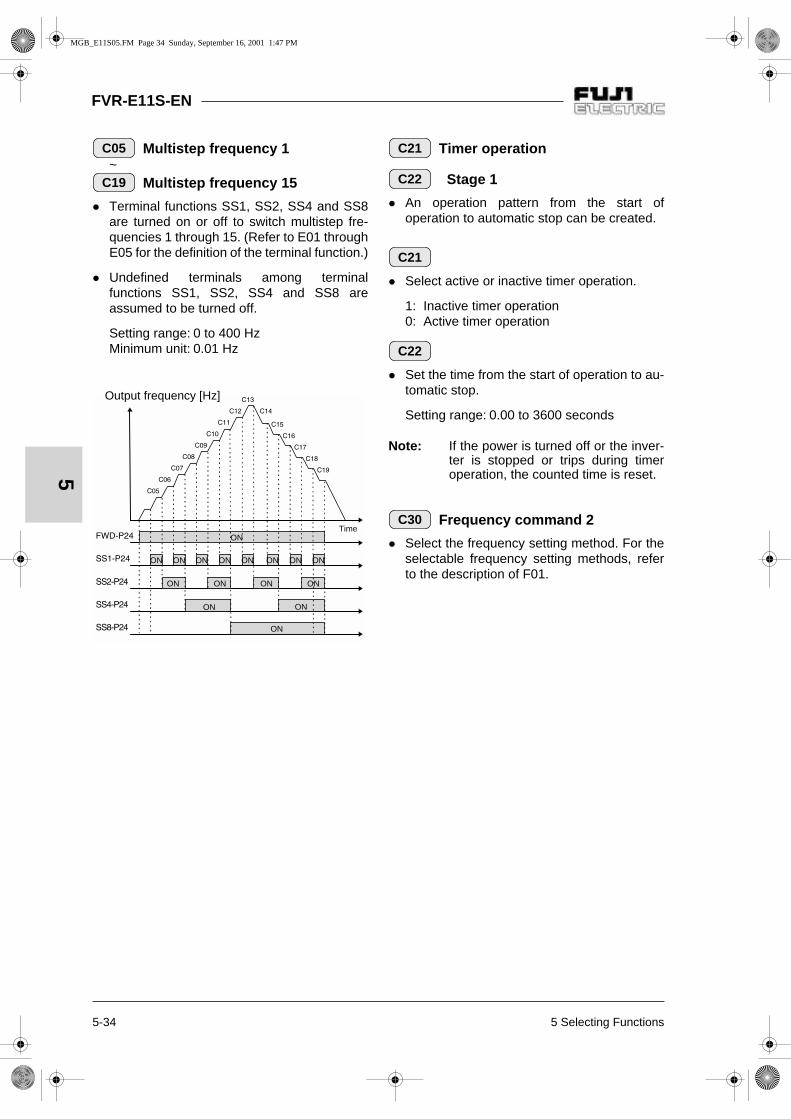
FVR-E11S-EN
5-34 5 Selecting Functions
5
Multistep frequency 1 ~
Multistep frequency 15
Terminal functions SS1, SS2, SS4 and SS8are turned on or off to switch multistep fre-quencies 1 through 15. (Refer to E01 throughE05 for the definition of the terminal function.)
Undefined terminals among terminalfunctions SS1, SS2, SS4 and SS8 areassumed to be turned off.
Setting range: 0 to 400 Hz Minimum unit: 0.01 Hz
Timer operation
Stage 1
An operation pattern from the start ofoperation to automatic stop can be created.
Select active or inactive timer operation.
1: Inactive timer operation0: Active timer operation
Set the time from the start of operation to au-tomatic stop.
Setting range: 0.00 to 3600 seconds
Note: If the power is turned off or the inver-ter is stopped or trips during timeroperation, the counted time is reset.
Frequency command 2
Select the frequency setting method. For theselectable frequency setting methods, referto the description of F01.
C05
C19
ON
ON ON ON ON
ON ON
ON
ON ON ON ON ON ON ON ON
Output frequency [Hz]
Time
C21
C22
C21
C22
C30
MGB_E11S05.FM Page 34 Sunday, September 16, 2001 1:47 PM

5 Selecting Functions 5-35
FVR-E11S-EN
5
Analog setting signal offset adjustment (Terminal 12)
Analog setting signal offset adjustment (Terminal C1)
Set the offset of the analog input (terminal[12], terminal [C1]).The offset can be set inthe range between -5.0 [%] and + 5.0 [%] ofthe maximum output frequency (in 0.1 [%]step).
Analog setting signal filter The analog signal supplied to control terminal
12 or C1 sometimes includes electric noise.Electric noise make the control unstable. Ad-just the time constant of the input filter to re-move the effects of electric noise.
Setting range: 0.00 bis 5.00 seconds
With a large time constant (setting), the con-trol becomes stable but there is a delay in thecontrol response. With a small time constant,the response is quick but the control beco-mes unstable.
If the setting is not clear, change the settingwhen the control is unstable or the response isslow.
Note: The function applies to both terminals[12] and [C1] (in common). However,when a PID feedback signal is input,H25 "PID control feedback filter" is ap-plied.
C31
C32
20mA
Maximumoutputfrequency
Frequencysettingvoltageinput
Maximumoutputfrequency
Frequency setting
Frequencysettingcurrentinput
Frequency setting
C33
MGB_E11S05.FM Page 35 Sunday, September 16, 2001 1:47 PM

FVR-E11S-EN
5-36 5 Selecting Functions
5
Number of motor 1 poles This parameter is the number of poles of
driven motor 1. Write a value to display cor-rect motor speeds (synchronized speeds) atthe LED.
Setting range: 2, 4, 6, 8, 10, 12 or 14
Motor 1 (Capacity) A standard applicable motor capacity is set
before shipment from the factory. Change thesetting to drive a motor rated at other than thestandard applicable motor capacity.
Setting range: 0.01 to 5.50 kW (3.7kW or smaller).0.01 to 11.00kW (5.5,7.5kW).
Set the standard applicable motor capacityspecified in section 9-1 "Standard Specificati-ons". The setting range should be betweenthe rank higher by one rank or lower by tworanks from the standard applicable motor ca-pacity. If the range is exceeded, accuratecontrol may not be possible. If a value bet-ween the standard applicable motor capacityand the capacity of another rank is set, thedata of the lower capacity is automaticallywritten for the data of the related functions.
After the setting of this function is changed,the settings of the following related functionschange to the data for the Fuji's three-phasestandard motor.-- P03 "Motor 1 (Rated current)"-- P06 "Motor 1 (No-load current)"-- P07 "Motor 1 (% R1)"-- P08 "Motor 1 (% X)"
Note: The settings of Fuji's three-phasestandard motor are the data for3-phase 400V/ 50 Hz.
Motor 1 (Rated current) This parameter is the rated current of motor 1.
Setting range: 0.00 to 99.9 A
Motor 1 (Tuning) The motor data is measured and the data is
automatically written.
Perform a tuning when the P06, P07 and P08data written in the inverter in advance differsfrom the actual motor data, that is, in the fol-lowing cases. Improvement in the control andcalculation accuracy is expected.
- When a motor other than the Fuji's stan-dard three-phase motor (4 poles) is used.
- When the impedance on the output sidecannot be ignored due to a long wiringlength between the inverter and the motoror connection of a reactor.
- When %R1 or %X is unknown due to anonstandard motor or a special motor.
P: Motor parameters
P01
P02
Setting State of operation
0 Inactive
1
The primary resistance (%R1) of the motor and the leakage reactance (%X) of the base frequency are measured while the motor is stopped, and the data is automatically written to P07 and P08.(Static tuning).
2
The primary resistance (%R1) of the motor and the leakage reactance (%X) of the base frequency are measured while the motor is stopped, then the no-load current (Io) is measured while the motor turns, and P06, P07 and P08 are automatically written.(Dynamic tuning).
P03
P04
MGB_E11S05.FM Page 36 Sunday, September 16, 2001 1:47 PM

5 Selecting Functions 5-37
FVR-E11S-EN
5
Tuning procedure1. Adjust the voltage and frequency according
to the characteristics of the motor. Adjust"F03", "F04", "F05" and "F06".
2. Enter the motor constants which cannot betuned. P02 "Capacity", P03 "Rated current",P06 "No-load current" (The no-load current isnot necessary in Dynamic tuning.).
3. To tune the no-load current, too, disconnectthe motor from the mechanical units andcheck that no danger occurs even if the motorturns.
4. Set P04 "Tuning" to "1" (motor stop) or "2"
(motor rotation) and press the key to wri-te the data, then issue an operation com-
mand (press the key or turn the FWD orREV terminal on) to start tuning. Tuning takesseveral seconds to several tens of seconds.(When the setting is "2", the motor accelera-tes to a half of the base frequency in the setacceleration/deceleration time to tune the no-load current, then decelerates. Therefore thetime necessary for tuning varies according tothe set acceleration/deceleration time.)
5. During tuning, the set data ("1" or "2") blinksrapidly and, upon the end of tuning, the nextfunction code (P05) is displayed. When theFWD or REV terminal is connected to start tu-ning, disconnect the terminal.
Note: Turn the BX and RST terminals offbefore starting tuning.
Motor 1 (Online tuning)
The motor temperature changes after opera-tion for a long time, changing the motorspeed. Use online tuning to reduce the speedfluctuation caused by temperature changesof the motor.
Motor 1 (No-load current) This parameter is the no-load current
(exciting current) of motor 1.
Setting range: 0.00 to 99.9 A
WARNINGIf auto tuning is set at "2", the motorturns at a half of the base frequency.Make sure that the motor is disconnec-ted from the mechanical units and thatno danger results from the rotation.Otherwise injuries could occur.
Setting State of operation
0 Inactive
1 Active
P05
P06
MGB_E11S05.FM Page 37 Sunday, September 16, 2001 1:47 PM

FVR-E11S-EN
5-38 5 Selecting Functions
5
Motor 1 (%R1 setting)
Motor 1 (%X setting) Write these parameters when a motor other
than the Fuji's standard three-phase motor isused and the impedance between the inver-ter and motor and motor constant are alreadyknown.
Calculate %R1 in the following formula.
whereR1: Resistance of primary coil of motor
for single phase [Ω]CableR: Resistance of output cable for single
phase [Ω]V: Rated voltage [V] I: Rated motor current [A]
Calculate %X in the following formula.
X1: Primary leakage reactance of motor [Ω]X2: Secondary leakage reactance of motor
(conversion to primary value) [Ω]XM: Motor excitation reactance [Ω]X Kabel: Reactance of output cable [Ω]V: Rated voltage [V] I: Rated motor current [A]
Note: Use the reactance effective at F04"Base frequency 1".
Add the value for a reactor and filterconnected to the output circuit. If the cablevalue can be ignored, the cable value shouldbe "0".
Motor 1 (Slip compensation control 1)
When the load torque changes, the motor slipchanges and the motor speed fluctuates.With the slip compensation control, a fre-quency proportional to the motor torque is ad-ded to the output frequency of the inverter tominimize the fluctuation of the motor speedcaused by torque changes.
Setting range: 0.00 to 15.00 Hz
Calculate the slip compensation data in thefollowing formula.
Slip compensation amount =
Slip = (Synchronized speed) – (Rated speed)
Motor 1 (Slip compensation response time 1)
Set the response time for slip compensation.
Setting range: 0.01 to 10.00 seconds
Note: With a small setting, the responsetime becomes shorter, but regenerati-on may cause overvoltage trippingwith some loads.In this case, set this function to longertime.
P07
P08
% R 1 = x 100 [%] R 1 + CableR
V / ( 3 x l)
%X = x100[%]X1+X2 XM/(X2 + XM)+ CableX
V / ( 3 x l)
P09
Base= x [Hz] frequencySlip [r/min]
Synchronized speed [r/min]
P10
MGB_E11S05.FM Page 38 Sunday, September 16, 2001 1:47 PM

5 Selecting Functions 5-39
FVR-E11S-EN
5
Total operation time The total power-on time of the inverter is
displayed. A number between 0 and 6500 isdisplayed, indicating 0 to 65000 hours. (Thetime is displayed in ten hours, though theinverter counts each hour. The time shorterthan one hour is not counted.)
Trip history A history of the latest four events of activation
of protective functions is stored in memory.
To call up each event, press the key.
Press the or key to confirm the
history.
The new record of protective operation is storedin the latest protective operation memory, andthe previous records are shifted one by one, andthe record of protective operation before the fourprevious ones is deleted
Data initializing(Data reset) This function restores (initializes) the factory
data over alterations made by the user.
Setting 0: Disabled1: Initialize
Press the and keys simultaneously
to change the setting to "1", then press the
key to initialize the settings of all
functions. After initialization is completed, the
setting automatically returns to "0".
Auto-reset (Times)
Auto-reset (Reset interval)When the protective function of the inverterwhich starts the retry function is activated,operation of the inverter protective function iscanceled to restart the inverter automaticallyinstead of an alarm and output stop.
Set the number of resetting cycles of theprotective function.
Setting range: 0 to 10 (0: retry inactive)
Procedure Displayexample
Remarks
1Call up
2
The latest protec-tive operation is displayed.
3
The protective operation before the previous one is displayed.
4
The protective operation before the two previous ones is displayed.
5
The protective operation before the three previous ones is displayed.
6
H: High Performance Functions
H01
H02
H 0 2H 0 2
1. O U 2
2. O H 1
3. O C 1
4. - - -
E n d
H03
H04
H05
H04
MGB_E11S05.FM Page 39 Sunday, September 16, 2001 1:47 PM

FVR-E11S-EN
5-40 5 Selecting Functions
5
Set the wait time from activation of a protec-tive function to resetting.
Setting range: 2 to 20 seconds
Inverter protective functions for retry and start.
When the data of H04 Retry (Times) is set to1 to 10, retry operation starts and the time setat H05 "Retry (Reset interval)" elapses, thenan inverter start command is automatically in-put. If the cause of the alarm has been remo-ved, the inverter starts without entering thealarm mode. If the cause of the alarmremains, the protective function is activatedagain to wait for the time set at H05 "Retry(Times)". If the cause of the alarm is not re-moved after the number of repetition cyclesset at H04 "Retry (Reset interval)", the inver-ter enters the alarm mode.
OC1, OC2, OC3 Overcurrent
OU1, OU2, OU3 Overvoltage
OH1 Overheated heat sink
dbHOverheated braking resistor
OL1 Overloaded motor 1
OL2 Overloaded motor 2
OLU Overloaded inverter
H05
WARNINGIf the retry function has been selected,the inverter may automatically restartaccording to some causes after trip-ping. (Design the machine so that hu-man safety is ensured after restarting.)Otherwise an accident could occur.
MGB_E11S05.FM Page 40 Sunday, September 16, 2001 1:47 PM

5 Selecting Functions 5-41
FVR-E11S-EN
5
Upon success of retry
Upon failure of retry
Active
H05 (Wait time)
Start
Time
DisappearanceOcurrence
0.1 s
Alarm
Protective function
Protective function automaticreset command
Output frequencyRetry count clear
5 minutes
Alarmreset
Active
End of retry
H04:(Count)setting
Firsttime
(Wait time)(Wait time)
DisappearanceOcurrence
Active Active Active
0.1 s 0.1 s 0.1 s
Alarm
Protective function
Protective function automaticreset command
Output frequency
Secondtime
MGB_E11S05.FM Page 41 Sunday, September 16, 2001 1:47 PM

FVR-E11S-EN
5-42 5 Selecting Functions
5
Fan stop operation With this function, the temperature of the heat
sink is detected while the inverter is turnedon, to turn on or off the cooling fan automati-cally. If this function is not selected, the coo-ling fan rotates at any time.
Setting 0: No on/off control.1: On/off control.
ACC/DEC pattern (Mode select) Select the acceleration/deceleration mode.
Setting 0: Inactive (linear accele-ration/deceleration)
1: S-curve acceleration/deceleration (Weak)
2: S-curve acceleration/deceleration (Strong)
3: Non-linear (for variable tor-que)
When the function is set at "1", "2" or "3", achange in the acceleration or deceleration timeduring acceleration or deceleration is notreflected immediately. The setting becomeseffective after a constant speed is reached or theinverter is stopped.
S-curve acceleration/deceleration To reduce the shock of the mechanical system,the change in the output frequency is madesmooth when the frequency is set.
Constant of each pattern
When the acceleration/deceleration time is extre-mely long or short, the result is linear acceleration/deceleration.
Curved acceleration/decelerationUse this option to minimize the acceleration/deceleration time for an acceleration/deceleration pattern of the motor including theoperation zone in the constant output range.
H06
H07
Output frequency
Slow S-shape pattern
Steep S-shape pattern
H07 = 1 (slow S-curve
pattern)
H07 = 2(steep S-curve
pattern)
Range of S-curve (α)
0.05 x (Maximum output frequency[Hz])
0.10 x (Maximum output frequency[Hz])
S-curvetime during acceleration(β acc)
0.10 x (Acce-leration time [s])
0.20 x (Acce-leration time [s])
S-curvetime during deceleration(β dec)
0.10 x (Dece-leration time [s])
0.20 x (Dece-leration time [s])
Output frequency
Acceleration time Deceleration timeMaximum out-put frequency
Set frequency
Base frequency
MGB_E11S05.FM Page 42 Sunday, September 16, 2001 1:47 PM

5 Selecting Functions 5-43
FVR-E11S-EN
5
Start mode (Rotating motor pickup)
This function smoothly starts a motor coa-sting due to an external force or the like aftermomentary power failure.The speed of the motor is detected upon po-wer recovery or restart and the same fre-quency as that for the motor speed is output.Therefore the motor starts smoothly without ashock. However, when the coasting speed ofthe motor converted in the inverter frequencyexceeds 120 Hz, setting of F03 "Maximumfrequency 1" or setting of F15 "Frequency li-miter (High)", the regular starting method isadopted.
Description of setting
1: This function is effective when the setting ofF14 "Restart after momentary power failure(Operation selection)" is "2" or "3". Starting is made at the same frequency asthat for the coasting speed.
2: Upon restart after momentary power failure,operation command ON and other startingmethods, the speed of the coasting motor isdetected and starting is made at the samefrequency as that for the coasting speed.
Note: When this function is used, use thefollowing setting to detect the accura-te rotation speed of the motor.
1. Set F09 Torque boost to "0" (automatictorque boost).
2. When a motor other than the one made byFuji Electric is used or when the wiring lengthis long, perform P04 Tuning.
Energy-saving operation When the output frequency for a small load is
constant (constant speed operation) and thesetting of F09 "Torque boost 1" is other than"0", the output voltage is automatically lowe-red to minimize the product (power) of thevoltage and the current.
Setting 0: Inactive1: Active
Notes:1. Use this function for fans, pumps or other
square reduction torque loads. If this functionis applied to a constant torque load or to anapplication with a rapidly changing load, thereis a delay in the control response.
2. The energy-saving operation is automaticallycanceled to resume regular operation duringacceleration or deceleration or when the tor-que limiter function is activated.
Dec mode Select the stopping method of the inverter af-
ter a stop command.
Setting 0: Normal (Deceleration to stop based on data of H07 "ACC/DEC pattern")
1: Coast-to-stop
Note: This function is not activated whenthe set frequency is lowered to stop.The function is activated only when astop command is input.
Setting Regular startingRestarting after
momentary power failure
0 Inactive Inactive
1 Inactive Active
2 Active Active
H09 H10
H11
MGB_E11S05.FM Page 43 Sunday, September 16, 2001 1:47 PM
FVR-E11S-EN
5-44 5 Selecting Functions
5
Instantaneous overcurrent limi-ting
When the motor load abruptly changes tocause a current exceeding the protective le-vel of the inverter to flow, the inverter tripsdue to the overcurrent. The Instantaneousovercurrent limiting function controls the in-verter output within the protective level evenupon an excessive load.
The operation level of the Instantaneousovercurrent limiting cannot be adjusted. Usethe torque limit function to set on output limi-tation.
The torque generated by the motor may be-come low in a Instantaneous overcurrent limi-ting state. Therefore deactivate themomentary overcurrent limit function for ap-plications such as the elevator where the tor-que generated by the motor must not be low.In this case, because the inverter trips due toan overcurrent when a current exceeding theprotective level of the inverter flows, use for-cible stopping measures by a mechanicalbrake or other protective measures.
Set value 0: Inactive1: Active
Auto-restart (Restart time) When the power supply to a running motor is
shut off or power failure occurs and the powersupply is quickly switched to another system,the phase of the voltage of the new systemdeviates from the phase of the voltage remai-ning in the motor and electrical or mechanicaltrouble may be developed. When switchingthe power supply system in a short time, writethe time for attenuation of the remainingvoltage from the motor after power shutoff.The setting is effective during restart aftermomentary power failure.
Setting range: 0.1 to 5.0 seconds
If the duration of momentary power failure isshorter than the wait time data, restart ismade after this time. If the duration of mo-mentary power failure is longer than the waittime data, restart is made after completion ofoperation preparation of the inverter (about0.2 to 0.5 second).
Auto-restart (Frequency fall rate) This function determines the drop ratio of the
output frequency for the synchronization bet-ween the output frequency of the inverter andthe motor speed, that is, the speed of syn-chronization. This function is also used todrop the frequency as a stall preventionfunction for an excessive load during regularoperation.
Setting range: 0.00, 0.01 to 100.0 Hz/s
Set "0.00" to drop according to the currentlyselected deceleration time.
Note: A large frequency drop ratio may cau-se temporary increase in the regene-ration energy from the load, activatingthe overvoltage protection function.On the contrary, a small frequencydrop ratio may cause long operationtime of the current limit function, acti-vating the inverter overload protectionfunction.
H12 H13
H14
MGB_E11S05.FM Page 44 Sunday, September 16, 2001 1:47 PM

5 Selecting Functions 5-45
FVR-E11S-EN
5
PID control (Mode select)~
PID control (Feedback filter) The PID control detects a control amount
(feedback value) from the sensor of the con-trolled object and compares it with the refe-rence value (set temperature, etc.). Upondifference between them, an action is takento reduce the difference. That is, this controlmethod makes the feedback value becomeconsistent with the reference value. This me-thod can be applied to flow control, pressurecontrol, temperature control and other pro-cess controls.
Because forward and reverse operation canbe selected for the output of the PID control-ler, the rpm of the motor can be increased ordecreased in relation to the output of the PIDcontroller.
Setting 0: Inactive1: Normal operation2: Inverse operation
The reference value can be given at F01"Frequency command 1" or directly inputfrom the keypad panel.Select an arbitrary terminal from E01 "X1 ter-minal (Function selection)" through E05 "X5(Function selection), and set data "9" (fre-quency command 2 / frequency command 1).To obtain the reference value from F01 "Fre-quency command 1", input an OFF signal tothe selected terminal. When inputting directlyfrom the keypad panel, turn the selected ter-minal on.
The process amount of the reference valueand feedback value can be displayed basedon the setting at E40 "Display coefficient A"and E41 "Display coefficient B".
H20
H25
Refe-rence
Drivingpart
Targetof control
Feedback value
H20
Inverter output frequency
Maximumfrequency
Normal
operation
Inverseoperation
PID output
100% refe-rence value or feedback value.
Displaycoefficient A
Displaycoefficient B
MGB_E11S05.FM Page 45 Sunday, September 16, 2001 1:47 PM

FVR-E11S-EN
5-46 5 Selecting Functions
5
PID control (Feedback signal)Select the feedback value input terminal andelectrical specification of the terminal. Selectone from the table below according to the speci-fications of the sensor.
Note:The feedback value of the PID control canbe input only in the positive polarity. Thenegative polarity (0 to -10 Vdc, -10 to 0 Vdc, etc.)cannot be input. Therefore the control cannot beapplied to reversible operation using the analogsignal.
H21
Setting Select item
0Control terminal 12, normal operation (voltage input 0 to +10V)
1Control terminal C1, normal operation (current input 4 to 20 mA)
2Control terminal 12, inverse operation (voltage input +10 to 0V)
3Control terminal C1, inverse operation (current input 20 to 4 mA)
Feedback value
Input
Normal
operation
Inverseoperation
Direct frequency setting at keypad
panel
Process amount setting at keypad
panel
Setting selected at F01
(Frequency setting 1)
E01 to E05 (Function)Frequency setting 1/2 switch
PIDcalculator
Forwardoperation
Reverseoperation
H20(Operation selection)
Terminal C1
E01 to E05 (Function)PID control cancel
Frequencycommand
Drivingpart
Controltarget
Signalreverse
Signalreverse
H21(Setting signal switch)
Terminal 12
Note: Numbers marked # indicate the setting of each function.
MGB_E11S05.FM Page 46 Sunday, September 16, 2001 1:47 PM

5 Selecting Functions 5-47
FVR-E11S-EN
5
PID control (P (P gain)) Generally speaking, P: gain, I: integral time
and D: differential time are not used alone.Functions are combined like: P control, PIcontrol, PD control and PID control.
P actionAn operation where there is proportional rela-tionship between the amount of operation(output frequency) and deviation is called Poperation. Therefore the P action outputs anoperation amount proportional to the deviati-on. However, the deviation cannot be elimi-nated by only the P action.
Setting range: 0.01 to 10.00 times
The P gain is a parameter which determinesthe degree of response to the deviation of Paction. With a large gain, the response isquick but hunting is likely to occur. With asmall gain, the response is stable but slow.
PID control (I (integral time)) I action
An operation where the speed of the changein the amount of operation is proportional tothe deviation is called I action. Therefore theI action outputs an operation amountobtained from integration of the deviation. Forthis reason, the I action is effective toconverge the control amount to the referencevalue. However, response is slow to thedeviation with abrupt changes.
Setting range: 0.0 Inactive, 0.1 to 3600 seconds
To determine the effect of the I action, I: integraltime is used as a parameter. With a long integraltime, the response is slow and reaction to an ex-ternal force is small. With a small integral time,the response is quick. When the integral time istoo small, there is hunting.
H22
Time
Deviation
Am
ount
of
oper
atio
n
Response
Time
H23
Time
Am
ount
of
oper
atio
nD
evia
tion
MGB_E11S05.FM Page 47 Sunday, September 16, 2001 1:47 PM

FVR-E11S-EN
5-48 5 Selecting Functions
5
PID control (D (Differential time)) D action
An operation where the amount of operationis proportional to the differential value of thedeviation is called D action. Therefore, the Daction outputs an operation amount obtainedfrom the differentiation of the deviation andthe response to abrupt changes is quick.
Setting range: 0.00 Inactive, 0.01 to 10.0 seconds
D: differential time is used as a parameter to de-termine the effect of the D action. With a long dif-ferential time, decrease in the vibration causedby the P action upon deviation is quick. With toolarge a differential time, vibration may becomelarger. With a small differential time, decrease inthe deviation becomes smaller.
PI controlDeviation remains with P action only. To eli-minate the remaining deviation, I action is ad-ded and P + I control is generally adopted.The PI control functions to always eliminatedeviation in spite of changes in the referencevalue and stationary disturbances. However,when the I action is strong, response to thedeviation with abrupt changes is slow.P action only can be used for loads with an in-tegral factor.
PD controlUpon deviation, the PD control generates anoperation amount larger than that obtained byD action only, to reduce the increase of thedeviation. When deviation is reduced tosmall, the function of the P action is madesmaller.For a load including integral factors to be con-trolled, the P action alone can cause huntingin the response due to the action of the inte-gral factors. The PD control is used in suchcases to decrease hunting of the P action tostabilize. That is, this control method is app-lied to loads having no braking in the processitself.
PID controlThe function of the I action to reduce the de-viation and the function of the D action to sup-press hunting are combined with the P action.Accurate responses without deviation are ob-tained.This control method is effective to loadswhich take time from generation of deviationto development of a response.
PID control (Feedback filter) This function provides a filter for the feedback
signal input at control terminal [12] or [C1].The filter makes the operation of the PID con-trol system stable. However, an excessivelylarge setting causes a poor response.
Setting range: 0.0 to 60.0 seconds
H24
Time
Dev
iatio
nA
mou
nt o
f op
erat
ion
H25
MGB_E11S05.FM Page 48 Sunday, September 16, 2001 1:47 PM

5 Selecting Functions 5-49
FVR-E11S-EN
5
PTC thermistor (Mode select) Select this function for a motor equipped with
a PTC thermistor for overheat protection.
Setting 0: Inactive1: Active
Connect the PTC thermistor as shown in thefigure. The protective operation is commonwith the external alarm input. Therefore theprotective function operates at the "externalalarm".
PTC Thermistor (Level) The voltage input at terminal [C1] is compa-
red with the set voltage and, when the inputvoltage at terminal [C1] is larger than the setvoltage (operation level), H26 "PTC thermi-stor (Operation selection)" is activated.
Setting range: 0.00 to 5.00 V(The setting smaller than 0.10 is handled
as 0.10)
The alarm temperature is determined by thePTC thermistor and the internal resistance ofthe PTC thermistor changes largely at thealarm temperature. Set the operation (volta-ge) level using this change of resistance.
From the figure of H26 "PTC thermistor (Opera-tion selection)", the 250 Ω resistor and the PTCthermistor (resistance Rp) configure a parallelcircuit. Therefore voltage VC1 (operation level) ofterminal [C1] is calculated in the following equa-tion.
The operation level can be set when Rp of theVC1 calculation equation is in the followingrange.
Rp1 < Rp < Rp2
To determine Rp simply, calculate the followingequation.
H26
Compa-
rator
1kΩ
PTCTher-mistor
H27
(Operation level)
ExternalAlarm
H27
PTC thermistor internal resistance
Alarmtemperature
Temperature
VC1 = x 10 [V]
250 Rp250 + Rp
250 Rp250 + Rp
1000 +
Rp = [Ω]Rp1 + Rp2
2
MGB_E11S05.FM Page 49 Sunday, September 16, 2001 1:47 PM

FVR-E11S-EN
5-50 5 Selecting Functions
5
Droop operationTo drive one machine with two or more motors,a larger load is exerted on the motor with a largerspeed. The droop control attributes droopingcharacteristics to the speed during loadfluctuation to balance the load. The drooping amount is calculated in the
following formula.
Setting range: -9.9 Hz to 0.0 Hz
Serial link (Function select) RS485 (standard accessory) can be connec-
ted as a link function (communicationfunction).
As a link function, the following items arepossible:1) Monitoring (monitoring of various data, confir-
mation of function code data)2) Frequency setting3) Operation command (FWD, REV and other
commands set for digital input)4) Function code data writing
Setting range: 0 to 3
The validity of communication can be switchedby a digital input. Set the link functions availablethrough communications.
The monitor function and function code data wri-ting function are always valid. When the commu-nication is disabled by means of a digital input, astate similar to setting "0" is obtained.
H28
X [Hz]Drooping content of speed at rated torque [r/min]Synchronized speed [r/min]
Drooping amount = Base frequency
Motor characteristics
Droop operation Droop operation inactiveTorque
SpeedSynchro-
nizedspeed
Rated torque
Setting Frequency settingOperation command
0 Invalid Invalid
1 Valid Invalid
2 Invalid Valid
3 Valid Valid
H30
MGB_E11S05.FM Page 50 Sunday, September 16, 2001 1:47 PM

5 Selecting Functions 5-51
FVR-E11S-EN
5
RS485 (address)~
RS485 (Response interval)Set the various conditions of RS485 communi-cation. Set according to the specifications of thehost unit. Refer to section 9-4 for protocol andother specifications.
Set the station address of RS485.
Setting range: 1 to 31
RS485 (Mode select on noresponse error)
Set the communication error handling pro-cess and the error handling timer value.
Setting range: 0 to 3
RS485 (Timer) Set the error handling timer value.
Setting range: 0.0 to 60.0 seconds
RS485 (Baud rate) Set the transmission speed.
RS485 (Data length) Set the data length.
RS485 (Parity check) Set the parity bit.
RS485 (Stop bits) Set the stop bit.
RS485 (No response error detection time)
In a system where there is always an accessto the station at certain intervals, no accesscaused by broken wire or other errors is de-tected and the inverter trips in Er8.
Setting range: 0 to 60 seconds0: No detection
RS485 (Response interval) Set the time taken until a response is sent
back to the host unit upon a request.
Setting range: 0.00 to 1.00 second
Setting Communication error handling process
0 Immediate Er 8 trip (coast to stop)
1Operation continues until the timer time elapses, then Er 8 trip.
2
Operation continues and retry is made until the timer time elapses, then Er 8 trip upon a communication error or continuation of operation upon no communication error.
3 Operation continues.
Setting Transmission speed
0 19200 bit/s
1 9600 bit/s
2 4800 bit/s
3 2400 bit/s
4 1200 bit/s
H31
H39
H31
H32
H33
H34
Setting Data length
0 8 bits
1 7 bits
Setting Parity bit
0 None
1 Even
2 Odd
Setting Stop bit
0 2 bits
1 1 bit
H35
H36
H37
H38
H39
MGB_E11S05.FM Page 51 Sunday, September 16, 2001 1:47 PM

FVR-E11S-EN
5-52 5 Selecting Functions
5
Maximum temperature of heat sink
The maximum value in each hour is displayedin degree C.
Maximum effective current The maximum value in each hour is displayed
in A.
Main circuit capacitor life The capacity of the capacitor in the main
circuit is displayed in %. For the measuringconditions, refer to section 8-2 (1)"Measurement of capacitance of capacitor inmain circuit".
Cooling fan operation time Integral hours is displayed. The displayed
time is 0 to 6500, indicating 0 to 65000 hours.(Though the displayed value is in ten hours,the inverter adds each hour. Operationshorter than one hour is not counted.)
Inverter ROM version The version of the software of the inverter is
displayed.
Keypad panel ROM version The version of the software of the keypad
panel is displayed.
Option ROM version For inverters with optional equipment, the
version of the optional software is displayed.
H40
H41
H42
H43
H44
H45
H46
MGB_E11S05.FM Page 52 Sunday, September 16, 2001 1:47 PM

5 Selecting Functions 5-53
FVR-E11S-EN
5
Maximum frequency 2 The maximum frequency output by the inver-
ter for motor 2. This parameter functions inthe same way as F03 "Maximum output fre-quency 1".For the description, refer to F03 "Maximumoutput frequency 1".
Base frequency 2 The maximum output frequency in the con-
stant torque zone of motor 2, that is, the out-put frequency at the rated output voltage.This parameter functions in the same way asF04 "Base frequency 1".For the description, refer to F04 "Base fre-quency 1".
Rated voltage 2 (at base frequency 2)
The rated output voltage supplied to motor 2.This parameter functions in the same way asF04 "Rated voltage 1".For the description, refer to F05 "Rated volta-ge 1".
Maximum voltage 2 (at maximum frequency 2
The maximum output voltage of the inverterfor motor 2. This parameter functions in thesame way as F06 "Maximum voltage 1". For the description, refer to F06 "Maximumvoltage 1".
Torque boost 2 The torque boost function of motor 2. This pa-
rameter functions in the same way as F09"Torque boost 1".For the description, refer to F09 "Torqueboost 1".
Electronic thermal overload relay for motor 2 (Select)
Electronic thermal overload relay for motor 2 (Level)
Electronic thermal overload relay for motor 2 (Thermal time constant)
The electronic thermal overload relayfunctions of motor 2. These parametersfunction in the same way as F10 through F12Electronic thermal overload relay for motor 1.For the description, refer to F10 through F12.
Torque vector control 2 The torque vector function of motor 2. This
parameter functions in the same way as F42"Torque vector control 1".For the description, refer to F42 "Torque vec-tor control 1".
Number of motor 2 poles The number of poles of driven motor 2. This
parameter functions in the same way as P01"Number of motor 1 poles".For the description, refer to P01 "Number ofmotor 1 poles)".
A: Alternative motor parameters
A01
A02
A03
A04
A05
A06
A07
A08
A09
A10
MGB_E11S05.FM Page 53 Sunday, September 16, 2001 1:47 PM

FVR-E11S-EN
5-54 5 Selecting Functions
5
Motor 2 (Capacity) The capacity of motor 2. This parameter
functions in the same way as P02 "Motor 1(Capacity)”. For the description, refer to P02"Motor 1 (Capacity)”. However, the function ofrelated motor data changes to A12 "Motor 2(Rated current)”, A15 "Motor 2 (No-load cur-rent)”, A16 "Motor 2 (%R1 setting)” and A17"Motor 2 (%X setting)”
Motor 2 (Rated current) The rated current of motor 2 . This parameter
functions in the same way as P03 "Motor 1(Rated current)”. For the description, refer to P03 "Motor 1(Rated current)”.
Motor 2 (Tuning) Tuning of motor 2. This parameter functions
in the same way as P04 "Motor 1 (Tuning)”.For the description, refer to P04 "Motor 1 (Tu-ning)”.
Motor 2 (Online tuning)
Online tuning of motor 2. This parameterfunctions in the same way as P05 "Motor 1(Online tuning)”. For the description, refer to P05 "Motor 1 (On-line tuning)”.
Motor 2 (No-load current) The no-load current of motor 2. This parame-
ter functions in the same way as P06 "Motor 1(No-load current)”. For the description, refer to P06 "Motor 1 (No-load current)”.
Motor 2 (%R1 setting)
Motor 2 (%X setting) %R1 and %X of motor 2. These parameters
function in the same way as P07 "Motor 1(%R1 setting)” and P08 "Motor 1 (%X set-ting)”. For the description, refer to P07 andP08.
Motor 2 (Slip compensation con-trol 2)
The slip compensation of motor 2. This para-meter functions in the same way as P09 "Slipcompensation control1”. For the description, refer to P09 "Motor 1 Slipcompensation control1”.
Motor 2 (Slip compensation re-sponse time 2)
Set the response time for slip compensationof motor 2. This parameter functions in thesame way as P10 "Slip compensation re-sponse time”. For the description, refer to P10 "Motor 1 Slipcompensation response time”.
A11
A12
A13
A14
A15
A16
A17
A18
A19
MGB_E11S05.FM Page 54 Sunday, September 16, 2001 1:47 PM

5 Selecting Functions 5-55
FVR-E11S-EN
5
Option selection0: Option inactive1: Option active
Set 1 when option card is used. Refer to the instruction manual of option card fordetail of optional functions.
O: Optional functions
o00
MGB_E11S05.FM Page 55 Sunday, September 16, 2001 1:47 PM
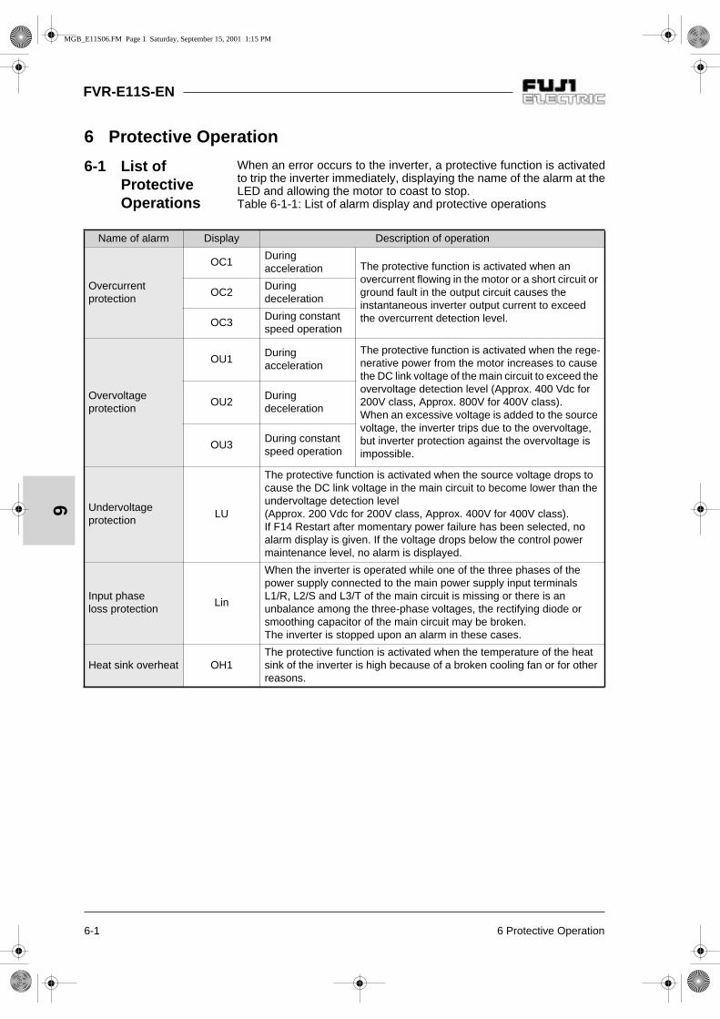
6-1 6 Protective Operation
FVR-E11S-EN
6
6 Protective Operation
6-1 List of Protective Operations
When an error occurs to the inverter, a protective function is activatedto trip the inverter immediately, displaying the name of the alarm at theLED and allowing the motor to coast to stop. Table 6-1-1: List of alarm display and protective operations
Name of alarm Display Description of operation
Overcurrentprotection
OC1Duringacceleration The protective function is activated when an
overcurrent flowing in the motor or a short circuit or ground fault in the output circuit causes the instantaneous inverter output current to exceed the overcurrent detection level.
OC2Duringdeceleration
OC3During constant speed operation
Overvoltageprotection
OU1Duringacceleration
The protective function is activated when the rege-nerative power from the motor increases to cause the DC link voltage of the main circuit to exceed the overvoltage detection level (Approx. 400 Vdc for 200V class, Approx. 800V for 400V class). When an excessive voltage is added to the source voltage, the inverter trips due to the overvoltage, but inverter protection against the overvoltage is impossible.
OU2Duringdeceleration
OU3During constant speed operation
Undervoltageprotection
LU
The protective function is activated when the source voltage drops to cause the DC link voltage in the main circuit to become lower than the undervoltage detection level (Approx. 200 Vdc for 200V class, Approx. 400V for 400V class). If F14 Restart after momentary power failure has been selected, no alarm display is given. If the voltage drops below the control power maintenance level, no alarm is displayed.
Input phase loss protection
Lin
When the inverter is operated while one of the three phases of the power supply connected to the main power supply input terminals L1/R, L2/S and L3/T of the main circuit is missing or there is an unbalance among the three-phase voltages, the rectifying diode or smoothing capacitor of the main circuit may be broken. The inverter is stopped upon an alarm in these cases.
Heat sink overheat OH1The protective function is activated when the temperature of the heat sink of the inverter is high because of a broken cooling fan or for other reasons.
MGB_E11S06.FM Page 1 Saturday, September 15, 2001 1:15 PM

6 Protective Operation 6-2
FVR-E11S-EN
6Table 6-1-1 List of alarm display and protective operations
Name of alarm Display Description of operation
External alarminput
OH2
The protective function is activated by a contact signal from an alarm contact of the external device such as the braking unit, braking resistor, and external thermal overload relay connected to the control circuit terminal (THR). Or an overheat protective function is activated by the PTC thermistor.
Braking resistor overheat
dbH
If the electronic thermal overload relay (for braking resistor) has been selected for function code F13, the protective function is activated upon a high operation frequency of the braking resistor to prevent the resistor from being burned due to the temperature rise.
Motor 1 overload
OL1If electronic thermal overload relay 1 has been selected for function code F10, the protective function is activated by a motor current excee-ding the set operation level.
Motor 2 overload
OL2If motor 2 has been selected and driven and electronic thermal overload relay 2 has been selected for function code A06, the protective function is activated by the current in motor 2 exceeding the set operation level.
Inverter overload OLUThe protective function is activated by an output current exceeding the overload current rating to protect the semiconductor elements in the main circuit of the inverter from high temperatures.
Memory error Er1The protective function is activated by a data writing error or other errors in the memory.
Keypad panel communicationerror
Er2The protective function is activated when a data transmission error or transmission stoppage is detected between the keypad panel and the control section in the keypad panel operation mode.
CPU error Er3The protective function is activated by electric noise or other errors developed in the CPU, or if P24 is overloaded.
Option errorEr4
Error during operation of optionEr5
Output phase loss Er7The protective function is activated during auto tuning when there is a broken wire or no connection in the inverter output circuit.
RS485communicationerror
Er8The protective function is activated when a communication error occurs during communication through RS485.
MGB_E11S06.FM Page 2 Saturday, September 15, 2001 1:15 PM

FVR-E11S-EN
6-3 6 Protective Operation
6
6-2 Alarm Reset
When the inverter trips, remove the cause then
press the key on the keypad panel or inputa reset command from the RST control terminalto reset the tripping state. Because the resetcommand is activated by an edge, supply thecommand in an OFF - ON - OFF sequence asshown in Fig. 6-2-1.
Figure 6-2-1
When resetting the tripping state, deactivate theoperation command. If the operation commandis left turned on, the inverter starts operation im-mediately after the error is reset.
Reset command
Keypad panel display
Alarmoutput OFF ON OFF
OFF ON OFF
Trip
Regular display(ready to operate)
Alarm display
10ms or longer
WARNINGWird der Befehl Zurücksetzengegeben solange noch ein Ein-Befehlansteht, läuft der Frequenzumrichterplötzlich wieder an, was zuGefahrenzuständen führen kann. AusSicherheitsgründen sollte daher vordem Zurücksetzen der Ein Befehl
WARNINGIf an alarm reset is made with the ope-ration signal turned on, a sudden startwill occur. Check that the operation sig-nal is turned off in advance.Otherwise an accident could occur!
MGB_E11S06.FM Page 3 Saturday, September 15, 2001 1:15 PM

7 Troubleshooting 7-1
FVR-E11S-EN
7
7 Troubleshooting
7-1 When Protective Function Goes Active
1) Overcurrent
Overcurrent during acceleration OC1
Overcurrent during deceleration OC2
Overcurrent during constant speed operation OC3
Remove a short circuit or the part
including a ground fault.
Yes Check if the motor connection terminal (U, V, W) circuit includes a short circuit or ground fault.
No No No
Reduce the load or increase the in-
verter capacity.
Yes Check if the load is too large.
No No No
Check if the tor-que boost amount can be decreased.
No Check if the torque boost amount is
proper.
Yes Yes
Decrease the tor-que boost amount.
Failure of the in-verter or mal-
function caused by electric noise
or other cause can be probable.
ContactFuji Electric.
No Check if the acceleration time is
too short for the load.
Yes No Check if the deceleration time is
too short for the load.
Yes No Check if there has been an abrupt change in the
load.
Yes
Set a longer time.
Yes Check if the acceleration time
can be made longer
No Yes Check if the deceleration time
can be made longer
No
Reduce the load fluc-tuation or increase
the inverter capacity.
The braking method must be examined.
Contact Fuji Electric.
Reduce the load fluc-tuation or increase
the inverter capacity.
No
MGB_E11S07.FM Page 1 Saturday, September 15, 2001 1:16 PM

7-2 7 Troubleshooting
FVR-E11S-EN
7
2) Overvoltage
Overcurrentduring
acceleration OU1
Overcurrentduring
deceleration OU2
Overcurrentduring constant speed operation
OU3
Decrease the source voltage to lower than the upper limit
in the specifica-tions.
No Check if the source voltage is within the range specified in the specifications.
Yes Yes Yes
Check if operation is observed after sudden removal of the load. Yes
No No No
Failure of the inverter or mal-function caused by electric noi-se or other cau-
se can be probable.Contact
Fuji Electric.
No Check if the DC link voltage of the main circuit during activation of the overvoltage is beyond the protective level.
Yes Yes Yes
No Check if operation is possible after sud-den acceleration.
Check if the deceleration time can be made longer.
Yes
Yes No No
Check if the accele-ration time can be
made longer.
YesSet a lon-ger dece-leration
time
No
Reduce the in-ertia moment.
Yes Check if the inertia moment of the load can be made smaller.
No No No
Check if a braking unit or DC control function is used. NoExamine applica-tion of a braking
unit or DC braking function.
Yes Yes Yes
Examination of the control method is necessary.Contact Fuji Electric.
MGB_E11S07.FM Page 2 Saturday, September 15, 2001 1:16 PM

7 Troubleshooting 7-3
FVR-E11S-EN
7
3) Undervoltage
4) Inverter inside overheat or heat sink overheat
Undervoltage LUCheck if power failure (including momentary
one) has occured.
Yes Reset and restart operation.
No
Check if there is failure of a device or poor contact in the power supply unit.
Yes Replace the defective device or repair the connection error.
Failure of the inverter or malfunction caused by
electric noise or other cau-se can be probable.Contact Fuji Electric.
NoYes
Check if the source voltage is within the range specified in the specifications.
YesCheck if there is a load
requiring a large starting current in the same power
supply system.
No
Check if operation is observed when the circuit
breaker and electromagnetic contactor
are turned on.
No
Check if the current (across P and N) and
the voltage of the main circuit are above the
detection level specified in Table 6-1-1.
No Yes Yes No
Examine the power supply system so that the specification values are satisfied.
Check if the power supply transformer capacity is
proper.
YesFailure of the inverter
is probable.Contact Fuji Electric.
Heat sink overheat OH1
Confirm the heat sink temperature at the keypad panel (H40).
Check if the temperature of the heat sink is -10 ˚C or lower.
YesThe detection circuit in the
printed circuit board is faulty. Contact Fuji Electric.
No
Check if the load exceeds the allowable limit.
Yes Reduce the load.
No
Check if the cooling fan rotates. No Replace the cooling fan.
Yes
Check if the path of cooling wind is blocked.
Yes Remove obstacles
No
Check if the ambient temperature is within the specification limits.
Yes Failure of the inverter or malfunction caused by electric noise or other
cause can be probable.Contact Fuji Electric.
No
improve the ambient temperature to within the specification limits.
MGB_E11S07.FM Page 3 Saturday, September 15, 2001 1:16 PM

7-4 7 Troubleshooting
FVR-E11S-EN
7
5) External alarm input
6) Inverter overload, motor overload
External alarm input OH2
Check if PTC input (H26) is set active.
No Yes
Check if control terminal function THR is assigned to X1 to X5 and an alarm
signal of the external device is connected
between the terminal and the P24 terminal.
No Connect the alarm signal contact.
Check if the PTC is activated.
YesA problem in the load or
cooling system of the motor is probable. Check the motor.
Yes No
Check if the alarm function of the connected external
device is activated.
NoRemove the cause of activation of the alarm
function.
Check if the operation level (H27) is set at the
proper value.
No Change to a proper value.
Yes Yes
Failure of the inverter or malfunction caused by electric noise or other
cause can be probable.Contact Fuji Electric.
Check if the external circuit (including
constants) is proper.
No Change to the correct external circuit.
Yes
Failure of the inverter or malfunction caused by electric noise or other
cause can be probable.Contact Fuji Electric.
Inverter overload OLU Motor overload OL1, OL2
Check if the characteristics of the electronic thermal overload relay
and the overload characteristics of the motor are in harmony.
No Connect an external thermal overload relay.
Yes
Check if the electronic thermal overload relay is properly set.
No Set to the proper level.
Yes
Check if the load is excessive. No
Failure of the inverter or malfunction caused by electric noise or other
cause can be probable.Contact Fuji Electric.
Yes
Reduce the load or increase the inverter capacity.
MGB_E11S07.FM Page 4 Saturday, September 15, 2001 1:16 PM

7 Troubleshooting 7-5
FVR-E11S-EN
7
7) Memory error Er1, keypad panel communication error Er2, CPU error Er3
8) Output wiring error
9) Input phase loss
Er1, 2, 3 display, irregular display or dark display.
Turn the power off, wait until the charge lamp (CRG) is unlit, then turn the power on again.
Check if the correct data is displayed on the LED. NoCheck if the connectors, sockets, ICs and other parts are properly connec-
ted and if there is no source of electric noise nearby.
NoCorrect the
point of trouble.
Yes Yes
The inverter is correct. Continue operation. Failure of the inverter.Contact Fuji Electric.
Output wiring error Er7
Check if the error occurs during tuning.
Yes No
Check if the circuits at terminal U, V and W are disconnected or there is a broken wire in them.
Yes Connect correctly or correct the wiring.
Check if the braking unit or braking resistor is er-rorneously connected.
Yes Connect correctly or correct the wiring.
No No
Check if the connector for connecting the key-pad panel is disconnec-
ted.
Yes Insert the connector.Failure of the inverter or malfunction caused by electric noise or other
cause can be probable.Contact Fuji Electric.
No
Check if control terminal FWD or REV is connec-ted with the P24 termi-
nal.
Yes Disconnect the connection.
No
Failure of the inverter or malfunction caused by electric noise or other
cause can be probable.Contact Fuji Electric.
Input phase loss
Check if all the power supply terminals L1/R, L2/S and L3/T of the main circuit are connected with cables.
No Connect all the three phases.
Yes
Check if the screw of the terminal block is loose. Yes Tighten the screw of the terminal block.
No
Check if the is a large voltage unbalance among three power supply phases.
Yes The power supply is faulty. Inspect the power supply system including wiring.
No
Failure of the inverter or malfunction caused by electric noise or other cause can be probable.
Contact Fuji Electric.
MGB_E11S07.FM Page 5 Saturday, September 15, 2001 1:16 PM

7-6 7 Troubleshooting
FVR-E11S-EN
7
7-2 When motor rotates incorrectly
1) The motor does not rotate.
The motor does not rotate.
Check if the charge lamp (CRG) is lit and that the keypad panel displays something.
No
Check if the circuit breaker and
electromagneticcontactor of the power supply are turned on.
No Turn them on.
Yes Yes
Remove the cause of the alarm, reset the
alarm then start operation.
Yes Check if the alarm mode screen is displayed.
Check if the voltage at the power supply terminal (L1/R, L2/S,
L3/T) is correct.
No
Check for voltage drop, phase lack, connection errors, poor contact and other problems and take
necessary actions.
No Yes
Check if the operation commands are input through the keypad panel or through the
control terminals.Check if a jumper or DC reactor is
connected across terminals P1 and P(+)
No Connect.
Continue operationif no error is found.
Yes Failure of the inverter is probable
Contact Fuji Electric.
Yes
Check if the motor rotates when the
RUN key is pressed.
No Check if the forward or reverse operation command is input
No
Check if the external circuit wiring across
control terminals FWD and REV and the P24 terminal is connected
correctly.
YesThe switch or relay is faulty, replace the
faulty parts.
No No
Press the up or down key to set the frequency
Yes
Check if the motor rotates when the up or down key is pressed.
No Check if the frequency is set.
No
Check if control terminals 13, 12, 11 and
C1 or, with multistep frequency selection, external circuit wiring across X1 to X5 and the P24 terminal is
connected correctly.
No Correct the wiring.
Set the correct frequency.
Yes
Check if the upper frequency limiter and the
set frequency are smaller than the starting
frequency.
Yes
The frequency setting unit, signal converter,
switch, relay contact or other unit is faulty.
Replace the faulty parts.
No
Keypadpanel
Controlterminal
Yes Yes
No Yes Yes
(Continued)
MGB_E11S07.FM Page 6 Saturday, September 15, 2001 1:16 PM

7 Troubleshooting 7-7
FVR-E11S-EN
7
No
Failure of motor.
Check that the voltage is present at the inverter
output terminals (U, V, W).
No Failure of the inverter is probable
Contact Fuji Electric.
NoYes
Check if the load is excessive.
Yes Check if the wiring to the motor is correct.
No Correct the wiring.
Yes
Check if the torque boost amount is
correctly set.
Yes
The load is excessively large and the motor is locked. Reduce the
load. For motors with a mechanical brake,
check that the brake is released.
No
Increase the torque boost amount.
Note: For the operation command frequen-cy setting and other data, select eachfunction and monitor at the keypadpanel.
The motor does not start when a coast-to-stopcommand or DC braking command is beinginput.
(Continued)
MGB_E11S07.FM Page 7 Saturday, September 15, 2001 1:16 PM

7-8 7 Troubleshooting
FVR-E11S-EN
7
2) The motor rotates but the speed does not change.
The change in the rotation speed of the motoris also small in the following cases:
F01 "Frequency command 1" and C30"Frequency command 2" are set at "3" and asignal is input from both of control terminals12 and C1, and there is no change in thesum of them.
The load is excessively large and the torquelimit and current limit functions are activated.
The motor rotates but the speed does not
change.
Check if the maximum frequency setting is
small.
Yes Set a larger value.
No
Change the setting. Yes Check if the upper/ lower frequency limiter
is activated.
Set the frequency.
YesNo
Yes
Check if the timer time is too long.
Check if the frequency setting method is
keypad panel operation, analog signal, multistep
frequency, or UP/DOWN method. Check if the operation method is
pattern operation.
Keypad paneloperation
Check if the speed changes when the up or
down key is pressed.
No
No
Check if the end of the pattern is reached.
Analog signal
Check if the frequency
setting signal(0 to 10 V, 4 to 20 mA) changes.
Yes
No Multistep frequencyor UP/DOWN
No
Check if the acceleration time and deceleration
time are identical.
Check if the wiring or the external circuits across
control terminals X1 through X5 and the P24
terminal are correct.
No Correct the wiring. No
Check if the wiring of the external
circuits with control terminals 13, 12, 11 and C1 are
correct.
No Yes Yes
Check if the frequency of each step for multi-step frequency is diffe-rent from each other.
No Correct the frequency setting.
Replace the frequency setting
unit and signal converter becau-se they are faulty.
Yes
Failure of the inverter or malfunction caused by electric noise or other
cause can be probable.Contact Fuji Electric.
NoCheck if the
acceleration time and deceleration time are
excessively long.
Yes
Change to the time suitable for the load.
Pat
tern
oper
atio
n
Yes
Yes
MGB_E11S07.FM Page 8 Saturday, September 15, 2001 1:16 PM

7 Troubleshooting 7-9
FVR-E11S-EN
7
3) The motor loses speed during acceleration.
4) Excessive heat generation from motor.
The motor loses the speed during acceleration.
Check if the acceleration time is too short.
Yes Increase the time.
No
Check if the inertia moment of the motor or load is too
large.
Yes Check if a special motor is used.
Yes ContactFuji Electric.
No No
Use thicker cables for the wiring between the inverter and the motor or reduce the
wiring length.
Yes Check if there is voltage drop at the
terminal of the motor.
Reduce the inertia moment of the load or increase the
inverter capacity.
No
Reduce the torque of the load or increase the
inverter capacity.
Yes Check if the torque of the load is too large.
No
Check if the torque boost amount
is proper.
Yes Failure of the inverter or malfunction caused by
electric noise or other cau-se can be probable.Contact Fuji Electric.No
Increase the torque boost amount.
Excessive heat generation from motor.
Check if the torque boost amount is too large.
Yes Reduce the torque boost amount.
No
Check if continuous operation is made at extremely low speed.
Yes Use a special motor designed for the inverter.
No
Check if the load is too large. Yes Reduce the load or increase the motor capacity.
No
Check if the output voltages (at U, V and W terminals) of the inverter are balanced.
Yes Failure of motor.
No
Failure of the inverter, malfunction due to electric noise or other
cause is probable. Contact Fuji Electric.
Note: Heat generation with a large frequen-cy setting may be caused by the wa-veform of the current. Contact FujiElectric.
MGB_E11S07.FM Page 9 Saturday, September 15, 2001 1:16 PM

8-1 8 Maintenance and Inspection
FVR-E11S-EN
8
8 Maintenance andInspection
Perform daily and periodic inspection to avoid trouble and keep reliableoperation for a long time. Take care of the following items during work.
8-1 Daily Inspection
Visually inspect errors in the state of operation from the outside withoutremoving covers while the inverter operates or while it is turned on.
1) Check if the expected performance (satisfying the standardspecification) is obtained.
2) Check if the surrounding environment satisfies the standardspecification.
3) Check that the display of the keypad panel is free from errors.
4) Check for abnormal noise, excessive vibration and bad smell.
5) Check for traces of overheat, discoloration and other defects.
8-2 Periodic Inspection
After stopping the operation, turn the power off and remove the front co-ver to perform periodic inspection.The smoothing capacitor at the DC section of the main circuit takestime to be discharged after the power is turned off. After checking thatthe charge lamp (CRG) is unlit, check that the DC voltage is lower thanthe safety level (25 VDC) using a multimeter or the like before startingwork.
1. Turn the power off and wait for at least five minutes before startinginspection (Further, check that the charge lamp is unlit and mea-sure the DC voltage across the P (+) and N (-) terminals to checkthat it is lower than 25V).Otherwise electric shock could occur!
2. Maintenance and inspection and parts replacement should bemade only by appointed persons. (Take off the watch, rings and other metallic matter before startingwork.)(Use insulated tools.)
3. Never remodel.Otherwise electric shock or injuries could occur!
WARNING
MGB_E11S08.FM Page 1 Saturday, September 15, 2001 1:16 PM

8 Maintenance and Inspection 8-2
FVR-E11S-EN
8
Check part Check item How to inspect Evaluation criteria
Environment
1) Check the ambient temperature, humidity, vibration and atmosphere (dust, gas, oil mist, water drops).
2) Check if tools or other foreign matter or dangerous objects are left around the equipment.
1) Check visually or measure using apparatus.
2) Visual inspection
1) The standard specification must be satisfied.
2) No foreign or dangerousobjects are left.
VoltageCheck if the voltages of the maincircuit and control circuit are correct.
Measure using a multimeter or the like.
The standard specification must be satisfied.
Keypad panel1) Check if the display is clear.2) Check if there is missing parts
in the characters.
1), 2)Visual inspection
1), 2)The display can be read and there is no fault.
Structure such as frame andcover
1) Abnormal noise and excessivevibration
2) Loose bolts (tightened parts)3) Deformation and breakage4) Discoloration and deformation caused
by overheat5) Stains and dust
1) Visual or hearinginspection
2) Retighten.3), 4), 5)
Visual inspection
1), 2), 3), 4), 5) No abnormalities
Mai
n ci
rcui
t
Common
1) Check if bolts and screws are tight and not missing.
2) Check the devices and insulators for deformation, cracks, breakage and discoloration caused by overheat and deterioration.
3) Check for foulness and dust.
1) Retighten2), 3)
Visual inspection
1), 2), 3) No abnormalities
Conductorand wire
1) Check the conductor for discoloration and distortion caused by overheat.
2) Check the sheath of the cable for cracks and discoloration.
1), 2)Visual inspection
1), 2) No abnormalities
Terminalblock
Damage Visual inspection No abnormalities
Smoothingcapacitor
1) Check for electrolyte leakage, discoloration, cracks and swelling of the case.
2) Check for safety valve protrusion and remarkably protruding valve
3) Measure the capacitance
1), 2) Visual inspection
3) * Monitor H42 Life judgement and measure with capacitance probe.
1), 2) No abnormalities
3) Capacitance (Initial value) x 0.85
>
MGB_E11S08.FM Page 2 Saturday, September 15, 2001 1:16 PM

8-3 8 Maintenance and Inspection
FVR-E11S-EN
8
Table 8-2-1 List of periodic inspection
Check part Check item How to inspect Evaluation criteria
Mai
n ci
rcui
t
Resistor1) Check for odor caused by overheat
and cracked insulator.2) Check for broken wire.
1) Smelling and visual inspection
2) Visual inspection or measurement with multimeter under disconnection of one lead
1) No abnormali-ties
2) Within 10 % of displayedresistance
Trans-former
Check for abnormal roaring noise and odor.
Hearing, visual and smelling inspection
No abnormalities
Relay1) Check for chatters during operation.2) Check for rough contacts.
1) Hearing inspection2) Visual inspection
1), 2)Noabnormalities
Con
trol
circ
uit
Controlprintedcircuitboard,connector
1) Check for loose screws and connectors.
2) Check for odor and discoloration.3) Check for cracks, breakage,
deformation and remarkable rust.4) Check the capacitors for electrolyte
leaks and deformation.
1) Retighten2) Smelling and visual
inspection3), 4)
Visual inspection
1), 2), 3), 4)Noabnormalities
Coo
ling
syst
em
Cooling fan
1) Check for abnormal noise and excessive vibration.
2) Check for loose bolts.3) Check for discoloration caused by
overheat.
1) Hearing and visual inspection, or turn manually (be sure to turn the power off).
2) Retighten.3) Visual inspection4) Life judgment based on
maintenance data*
1) Smooth rotation2), 3)
Noabnormalities
Ventilationpath
Check the heat sink, intake and exhaust ports for clogging and foreign matter.
Visual inspection No abnormalities
* Judgment of life using maintenance dataThe maintenance data of function codes H42and H43 can be used to display data for thejudgment of the capacitance of the capacitorin the main circuit and the life of the coolingfan to obtain a measure for the judgment ofparts replacement. The capacitor life forecastsignal is issued at the Y1 and Y2 terminals ac-cording to the measured capacitance after thecapacitance of the capacity reaches 85%.
Remarks:Remove foulness using cleaning clothwhich is chemically neutral.Use a vacuum cleaner to removedust.
MGB_E11S08.FM Page 3 Saturday, September 15, 2001 1:16 PM

8 Maintenance and Inspection 8-4
FVR-E11S-EN
8
1) Measurement of capacitance of capacitorin main circuitThis inverter is provided with a function wherethe capacitance of the main circuit capacitoris automatically measured upon shutoff of theinverter under certain conditions and it isdisplayed on the keypad panel upon power-up.The capacitance of the capacitor is displayedin the reduction ratio (% display) of the initialvalue stored inside the inverter beforeshipment.
Procedure of measurement of capacitorcapacitance1. Remove the optional card from the inverter
if it is mounted. Disconnect the braking unitor direct current bus to another inverterfrom the P (+) and N (-) terminals of themain circuit if there is any.The power factor improving reactor(DC reactor) may not be disconnected.
2. Turn the digital inputs (FWD, REV, X1-X5)at the control terminals off. Disconnect theRS 485 communication terminal if it is con-nected.
3. Turn the main power supply on. Checkthat the cooling fan rotates. Check that theinverter is stopped. (The "OH2 externalalarm" caused by deactivated digital inputterminals does not cause a problem.)
4. Turn the main power supply off.
5. After the charge lamp is unlit completely,turn the main power supply on again.
6. Monitor function code H42 to check the ca-pacitor capacitance (%).
2) Life of cooling fanFunction code H43 indicates the total opera-tion time of the cooling fan. The time is inte-grated in units of an hour and fractionsshorter than an hour are ignored.The actual life of the fan is largely effected bythe temperature. Take the time as a measure.
Table 8-2-2 Measure for judgment of life based onmaintenance data
1) Assumed life of cooling fan at ambient inverter tempe-rature of 40 ˚C.
Part Judgment level
Main circuit capacitor85 % or lower of the initial value
Cooling fan
30000 hours(4.0 kW or less), 25000 hours (5.5 kW or more) 1)
MGB_E11S08.FM Page 4 Saturday, September 15, 2001 1:16 PM

8-5 8 Maintenance and Inspection
FVR-E11S-EN
8
Table 8-3-1 Meters for measurement of main circuit
Fig. 8-3-1 Connection of meters
8-3 Measurement of Electrical Amounts in Main Circuit
Because the voltage and current of the power supply (input) of themain circuit of the inverter and the output (motor) include harmoniccomponents, the indicated value varies according to the type of themeter. Use meters indicated in Table 8-3-1 when measuring with me-ters for commercial frequencies. Marketed power factor meters measuring phase difference betweenthe voltage and current cannot measure the power factor. To obtain thepower factor, measure the power, voltage and current on each of theinput and output sides and calculate in the following formula.
In case of Three-phase
In case of Single-phase
Item
Input (power supply) side Output (motor) sideLink voltage(P(+) - N(-))
Voltage Current Voltage Current
Name of meter
AmmeterAR, S, T
VoltmeterVR, S, T
WattmeterWR, S, T
AmmeterAU, V, W
VoltmeterVU, V, W
WattmeterWU, V, W
DC voltmeterV
Type of meter
Moving iron type
Rectifier or moving iron
type
Digital power meter
Moving iron type
Rectifier typeDigital power
meterMoving coil
type
Symbolof meter
Note: When the output voltage is measured by a rectifier type, an er-ror may be included. To increase the accuracy, use a digital AC power meter.
Power factor = x100 [%]Electric power [W]
3 x Voltage [V] x Current [A]
Power factor = x100 [%]Electric power [W]
Voltage [V] x Current [A]
Power supplyMotor
MGB_E11S08.FM Page 5 Saturday, September 15, 2001 1:16 PM
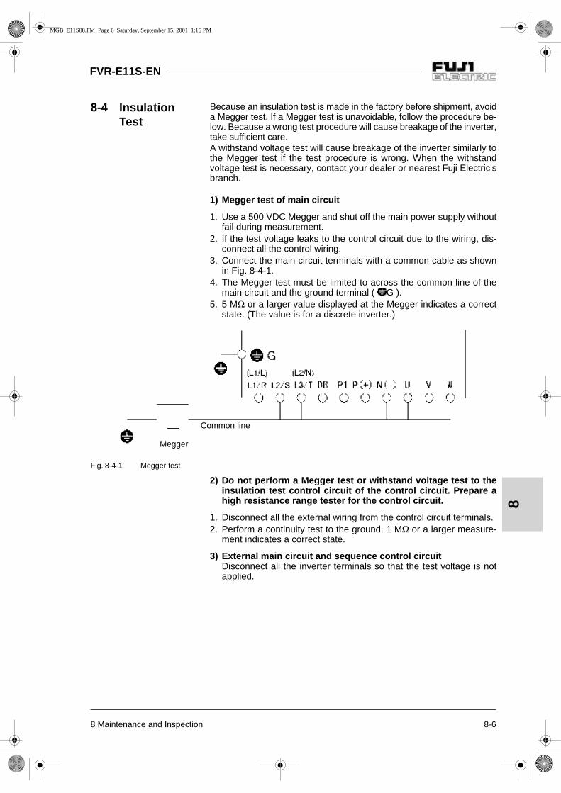
8 Maintenance and Inspection 8-6
FVR-E11S-EN
8
Fig. 8-4-1 Megger test
8-4 Insulation Test
Because an insulation test is made in the factory before shipment, avoida Megger test. If a Megger test is unavoidable, follow the procedure be-low. Because a wrong test procedure will cause breakage of the inverter,take sufficient care.A withstand voltage test will cause breakage of the inverter similarly tothe Megger test if the test procedure is wrong. When the withstandvoltage test is necessary, contact your dealer or nearest Fuji Electric'sbranch.
1) Megger test of main circuit
1. Use a 500 VDC Megger and shut off the main power supply withoutfail during measurement.
2. If the test voltage leaks to the control circuit due to the wiring, dis-connect all the control wiring.
3. Connect the main circuit terminals with a common cable as shownin Fig. 8-4-1.
4. The Megger test must be limited to across the common line of themain circuit and the ground terminal ( G ).
5. 5 MΩ or a larger value displayed at the Megger indicates a correctstate. (The value is for a discrete inverter.)
2) Do not perform a Megger test or withstand voltage test to theinsulation test control circuit of the control circuit. Prepare ahigh resistance range tester for the control circuit.
1. Disconnect all the external wiring from the control circuit terminals.2. Perform a continuity test to the ground. 1 MΩ or a larger measure-
ment indicates a correct state.
3) External main circuit and sequence control circuitDisconnect all the inverter terminals so that the test voltage is notapplied.
Megger
Common line
MGB_E11S08.FM Page 6 Saturday, September 15, 2001 1:16 PM

FVR-E11S-EN
8-7 8 Maintenance and Inspection
8
8-5 Replacement Parts
The life of the part is determined by the type ofthe part. The life of the part varies according tothe environment and operating conditions, andreplacement according to Table 8-5-1 is recom-mended.
Table 8-5-1 Replacement parts
8-6 Inquiries about Product and Guarantee
1) When making an inquiryUpon breakage of the product, uncertainties,failure or inquiries, report the following infor-mation to your dealer or nearest Fuji Electric'sbranch.
a) Inverter typesb) SER NO. (serial number of equipment)c) Date of purchased) Inquiries (for example, point and extent of
breakage, uncertainties, failure phenome-na, and other circumstances)
2) Guarantee of the product The product guarantee term is one year afterthe purchase or 18 months from the monthand year of production specified on thenameplate, whichever comes first.However, the product will not be repaired freeof charge in the following cases, even if theguarantee term has not expired.
a) The cause includes incorrect usage orinappropriate repairs or remodeling.
b) The product is used outside the standardspecified range.
c) The failure is caused by dropping, damageor breakage during transportation after thepurchase.
d) The cause is earthquake, fire, storm orflood, lightening, excessive voltage, orother types of act of God or secondarydisasters.
Name of partStandard re-placement
years
Replacementmethod and others
Cooling fan 3 yearsReplace with a new part.
Smoothing capacitor
5 yearsReplace with a
new part. (Replace after inspection.)
Electrolytic capacitors on printed
circuit board
7 years
Replace with new circuit board.
(Replace after inspection.)
Other parts -Determine after
inspection.
MGB_E11S08.FM Page 7 Saturday, September 15, 2001 1:16 PM

9 Specifications 9-1
FVR-E11S-EN
9
9 Specifications
9-1 Standard Specifications
9-1-1 Single-phase 200V inputItem Detail specifications
Inverter type FVR E11S-7EN 0.1 0.2 0.4 0.75 1.5 2.2
Nominal applied motor 1) [kW] 0.1 0.2 0.4 0.75 1.5 2.2
Output ratings
Rated capacity 2)[kVA]
0.31 0.59 1.1 1.9 3.1 4.3
Rated voltage 3) [V] Three-phase 200V / 50 Hz, 200V, 220V, 230V / 60 Hz (with AVR function)
Rated current 4) [A]0.8
(0.7)1.5
(1.4)3.0
(2.5)5.0
(4.0)8.0
(7.0)11
(10)
Overload capability150 % of rated output current for 1 min. 200 % of rated output current for 0.5 s
Rated frequency [Hz] 50, 60Hz
Input ratings
Phases, Voltage, Frequency
Single-phase 200 to 240 V / 50 to 60 Hz 10)
Voltage/frequencyfluctuation
Voltage: +10 to -10% Frequency: +5 to -5%
Momentary voltage dip capability 5)
Operation continues at 165V or higher voltage.When the input voltage drops below 165V from the rated voltage, operation continues for 15 ms.
Ratedcurrent9) [A]
With DCR 1.2 2.0 3.5 6.5 11.8 17.7
WithoutDCR
2.3 3.9 6.4 11.4 19.8 28.5
Required power supply capacity 6) [kVA]
0.3 0.4 0.7 1.3 2.4 3.6
Braking
Braking torque 7) [%] 100 70 40
Braking torque 8) [%] 150 %
DC braking Starting frequency: 0.0 to 60 Hz, braking current (0 to 100% in 1% increment), braking time (0.0
to 30.0 s)
Enclosure(IEC60529) IP20
Cooling method Natural cooling Fan cooling
Mass [kg] 0.6 0.7 1.2 1.8 1.9
Notes:1) The applicable standard motor indicates the case for a 4P standard motor made by
Fuji Electric.2) The rated capacity indicates the case for 230V output voltage.3) Voltages larger than the source voltage cannot be output.4) Amperage values in parentheses () are applicable to operation with 4 kHz or
higher carrier frequencies (F26 = 4 or more) or ambient temperatures exceeding40 degree C.
5) Tests at standard load condition (85% load)6) Indicates the value when using a DC reactor (DCR).7) Indicates the average braking torque for decelerating and stopping a discrete
motor from 60 Hz. (Varies according to the efficiency of the motor.)8) Indicates the value with an external braking resistor (option).9) Calculated on assumption that the inverter is connected to 500kVA power supply.10)Safe separation for control interface of this inverter is provided when this inverter is
installed in overvoltage category II. Basic insulation for control interface of thisinverter is provided when this inverter is installed in overvoltage category III.
MGB_E11S09.FM Page 1 Saturday, September 15, 2001 1:17 PM

9-2 9 Specifications
FVR-E11S-EN
9
9-1-2 Three-phase 400V inputItem Detail specifications
Inverter type FVR E11S-4EN 0.4 0.75 1.5 2.2 4.0 5.5 7.5
Nominal applied motor 1) [kW] 0.4 0.75 1.5 2.2 4.0 5.5 7.5
Output ratings
Rated capacity 2)[kVA]
1.0 1.7 2.6 3.9 6.4 9.3 12
Rated voltage 3) [V] Three-phase 380,400,415V/50Hz, 380,400,440,460V/60Hz (with AVR function)
Rated current 4) [A]1.5
(1.4)2.5
(2.1)3.7
(3.7)5.5
(5.3)9.0
(8.7)13
(12)18
(16)
Overload capability150 % of rated output current for 1 min. 200 % of rated output current for 0.5 s
Rated frequency [Hz] 50, 60Hz
Input ratings
Phases, Voltage, Frequency
Three-phase 380 to 480 V / 50 to 60Hz 11)
Voltage/frequencyfluctuation
Voltage: +10 to -10% Voltage unbalance 2% or less 10)Frequency: +5 to -5%
Momentary voltage dip capability 5)
Operation continues at 300V or higher voltage.When the input voltage drops below 300V from the rated voltage, operation continues for 15 ms.
Ratedcurrent9) [A]
With DCR 0.82 1.5 2.9 4.2 7.1 10.0 13.5
WithoutDCR
1.8 3.5 6.2 9.2 14.9 21.5 27.9
Required power supply capacity 6) [kVA]
0.6 1.1 2.1 3.0 5.0 7.0 9.4
Braking
Braking torque 7) [%] 70 40 20
Braking torque 8) [%] 150 %
DC braking Starting frequency: 0.0 to 60 Hz, braking current (0 to 100% in 1% increment),
braking time (0.0 to 30.0 s)
Enclosure(IEC60529) IP20
Cooling method Natural cooling Fan cooling
Mass [kg] 1.1 1.2 1.3 1.4 1.9 4.5
Notes:1) The applicable standard motor indicates the case for a 4P standard motor made by
Fuji Electric.2) The rated capacity indicates the case for 415V output voltage.3) Voltages larger than the source voltage cannot be output.4) Amperage values in parentheses () are applicable to operation with 4 kHz or
higher carrier frequencies (F26 = 4 or more) or ambient temperatures exceeding40 degree C.
5) Tests at standard load condition (85% load)6) Indicates the value when using a DC reactor (DCR).7) Indicates the average braking torque for decelerating and stopping a discrete
motor from 60 Hz. (Varies according to the efficiency of the motor.)8) Indicates the value with an external braking resistor (option).9) Calculated on assumption that the inverter is connected to 500kVA power supply.10)Refer to IEC61800-3 5.2.3.11)Safe separation for control interface of this inverter is provided when this inverter is
installed in overvoltage category II. Basic insulation for control interface of thisinverter is provided when this inverter is installed in overvoltage category III.
MGB_E11S09.FM Page 2 Saturday, September 15, 2001 1:17 PM

9 Specifications 9-3
FVR-E11S-EN
9
9-2 Common Specifications
Item Detail specifications
Out
put f
requ
ency
Adj
ustm
ent
Maximumfrequency
50 to 400 Hz variable
Basefrequency
25 to 400 Hz variable
Startingfrequency
0.1 to 60.0 Hz variable, Holding time : 0.0 to 10.0s
Carrierfrequency
0.75 to 15 kHz (The carrier frequency may automatically drop to 0.75 kHz to protect the inverter. )
AccuracyAnalog setting: Within +/- 0.2 % (+25 ±10 ˚C)Digital setting: Within +/- 0.01 % (-10 bis +50 ˚C)
Setting resolution
Analog setting: 1/3000 of maximum output frequencyKeypad panel setting: 0.01 Hz (99.99 Hz or lower), 0.1 Hz (100.0 to 400.0 Hz)Link setting: 1/20000 of Maximum frequency
(0.003Hz at 60Hz,0.006Hz at 120Hz,0.02Hz at 400Hz)or 0.01Hz (Fixed)
Con
trol
Voltage/freq.Characteristics
Adjustable at base and maximum frequency, with AVR control : 80 to 240 V(200V class),160 to 480V(400V class)
Torque boostAutomatic: Automatic torque boost can be selected with code setting.Manual: Setting by codes 1 to 31 (Boost for Variable torque available)
Starting torqueStarting torque 200% or above (with dynamic torque vector turned on, during 0.5 Hz operation)
DC brakingBraking time (0.0 to 30.0 s), braking current (0 to 100%), braking starting frequency (0.0 to 60.0 Hz) variable
Control methodSinusoidal PWM (Dynamic torque vector control) with "current vibration suppression function" and "dead time compensation function"
Operation method
Keypad operation: starting and stopping with and keys.(Keypad panel)
Digital input signal: forward (reverse) operation, stop command (3-wire operation possible), coast-to-stop command, external alarm, error reset, etc.
Link operation: RS485 (Standard) Profibus-DP,Interbus-S,DeviceNet,Modbus Plus,CAN open (Option)
MGB_E11S09.FM Page 3 Saturday, September 15, 2001 1:17 PM

9-4 9 Specifications
FVR-E11S-EN
9
Item Detail specifications
Con
trol
Frequency setting
Keypad operation: key and key.Setting with potentiometer (external potentiometer: 1 to 5 k
Ω, 1/2 W)Setting with 0 to ± 5 V DC.Setting with 0 to ± 10 V DC.Setting with 4 to 20 mA DC.0 to +10 V DC / 0 to 100% can be switched to +10 to 0 V DC / 0 to 100% externally.4 to 20 mA DC / 0 to 100% can be switched to 20 to 4 mA DC / 0 to 100% externally.
(UP/DOWNcontrol)
An external signal can be used to control the UP or DOWN command.
(Multistepfrequency)
Up to 16 different frequencies can be selected by digital input signals.
(Link operation)Link operation: RS485 (Standard)
Profibus-DP, Interbus-S, DeviceNet, Modbus Plus,CAN open (Option)
Acceleration / deceleration time
Variable setting in 0.01 to 3600s range. (2 sets of time can be set internally for each of acceleration and deceleration.)
(Mode select) Linear, S-curve (weak, strong), Non-linear available.Frequency limiter The high and low frequency limits can be set variably in a 0 to 100% range in Hz.Bias frequency Can be set variably in -400 to 400 Hz range.Gain(frequency setting)
Can be set variably in a 0 to 200% range.
Jump frequency control
Three jump frequencies and jump width (0 to 30 Hz) can be set.
Rotating motor pickup(Flying start)
Operation without shock is possible.
Auto-restart after momentary power failure
The motor speed can be detected after power recovery so that the motor is started at the speed.
Slip compensation control
The load during regular operation can be detected for the control of the frequency. Thecompensation value can be set variably in a 0.00 to +15.00 Hz range to the ratedfrequency.
Droop operationThe load during regular operation can be detected for the control of the frequency. The compensation value can be set in a -9.9 to 0.0 Hz range to the rated frequency. (Speed droop characteristics)
Torque limiter
When the load torque in the driving or braking mode exceeds the setting, the frequency is controlled to control the load torque to an almost constant level.The limiting torque can be set 20 to 200% and the driving and braking torque values can be independently set. The second torque limits can be set.
MGB_E11S09.FM Page 4 Saturday, September 15, 2001 1:17 PM

9 Specifications 9-5
FVR-E11S-EN
9
Item Detail specificationsC
ontr
ol
PID control
This function can control flowrate, pressure, etc. with analog feedback signal. The reference and feedback values are displayed in %.Reference signal
Keypad operation: key and key. : 0.0 to 100%Voltage input (Terminal 12) : 0 to 10V DCCurrent input (Terminal C1) : 4 to 20mA DCMultistep frequency setting : Setting freq./Max. freq.x100%RS485 : Setting freq./Max. freq.x100%
Feedback signalTerminal 12 (0 to +10V DC or +10 to 0V DC)Terminal C1(4 to 20mA DC or 20 to 4mA DC)
Second motor’s setting
The V/f pattern of the second motor can be internally set for selection by means of an external signal.The constant of the second motor can be internally set for selection by means of an external signal.The electronic thermal overload relay of the second motor can be internally set for selection by means of an external signal.
Energy saving operation
Weak magnetic flux can be set for small loads for operation with an increased motor efficiency.
Dis
play
During operation/stop
The keypad panel can be extended. (Optional 5m extension cable is available.)7-segment LED display items• Set frequency • Output frequency • PID setting/feedback value• Output current • Motor r/min• Output voltage • Line speed(A soft filter is provided to attenuate the fluctuation in the displayed value.)A charge lamp indicates power supply.
When setting The function code and data code are displayed.
When tripping
[The cause of tripping is displayed.]• OC1 (overcurrent: during acceleration)• OC2 (overcurrent: during deceleration)• OC3 (overcurrent: during constant speed operation)• OU1 (overvoltage: during acceleration)• OU2 (overvoltage: during deceleration)• OU3 (overvoltage: during constant speed operation)• LU (undervoltage)• Lin (input phase loss) (for 3-phase inverter)• dbH (external damping resistor overheat (thermal overload relay))• OH1 (overheat: heat sink)• OH2 (overheat: external thermal overload relay)• OL1 (overload: motor 1)• OL2 (overload: motor 2)• OLU (overload: inverter)• Er1 (memory error)• Er2 (keypad panel communication error)• Er3 (CPU error)• Er4 (option error)• Er5 (option error)• Er7 (output wiring error) (impedance imbalance)• Er8 (RS485 communication error)
During operation, when tripping
The latest four records of trip history are stored and displayed.
MGB_E11S09.FM Page 5 Saturday, September 15, 2001 1:17 PM

9-6 9 Specifications
FVR-E11S-EN
9
Item Detail specifications
Pro
tect
ion
Overloadprotection
Inverter protection electronic thermal overload relay.
Overvoltageprotection
An excess in the DC link circuit voltage (approx. 400 V DC for 200V class, approx. 800V DC for 400V class) is detected for inverter protection.
Overcurrentprotection
The inverter is protected against an overcurrent caused by an overload on the output side.
Surgeprotection
The inverter is protected against a surge voltage penetrating between the power supply cable of the main circuit and the ground.
Undervoltageprotection
Voltage drop (approx. 200 V DC for 200V class, approx. 400V DC for 400V class ) in the DC link circuit voltage is detected to stop the inverter.
Overheatprotection
The inverter is protected against failure and overload of the cooling fan.
Short-circuitprotection
The inverter is protected against an overcurrent caused by a short-circuit on the output side.
Ground fault protection
The inverter is protected against an overcurrent caused by ground fault in the output wiring.* Detection when starting
Motor protection
Electronic thermal overload relays protect general purpose motors and Fuji's inverter motor.The thermal time constant can be adjusted to 0.5 to 10.0 min.Second electronic thermal overload relay can be provided. (Switching with external signal)
Braking resistor protection
Upon an overheat of the damping resistor (external unit), discharging operation and inverter operation stop.
Stall prevention (simple torque limit)
• When the output current exceeds the limit during acceleration, the frequency change is stopped to avoid overcurrent stop.
• When the output current exceeds the setting during constant speed operation, the frequency is decreased to maintain an almost constant torque.
• When the DC voltage exceeds the limit during deceleration, the frequency change is stopped to avoid overvoltage stop.
Input phase loss protection
The inverter is protected against phase loss in the input voltage.
Output phase loss protection
An unbalance in the impedance of the output circuit is detected to output an alarm. (Error during tuning only)
Auto reset The number of retries and wait time can be set for the alarm stop.
MGB_E11S09.FM Page 6 Saturday, September 15, 2001 1:17 PM

9 Specifications 9-7
FVR-E11S-EN
9
Item Detail specificationsE
nviro
nmen
t
Installationlocation
• Indoors• Places without corrosive gases, flammable gases or dust (degree of pollution: 2)• Places without direct sunlight
Ambienttemperature
-10 to +50 ˚C
Relative humidity 5 to 95% RH (without condensation)Altitude 1000 m Max. (Atmospheric pressure 86 to 106 kPa)
Vibration
3 mm 2 to 9 Hz, 9,8 m/s2 9 to 20 Hz,2 m/s2 20 to 55 Hz,1 m/s2 55 to 200 Hz,
Storagetemperature
-25 to +65 ˚C
Storage humidity 5 to 95 % RH (without condensation)
MGB_E11S09.FM Page 7 Saturday, September 15, 2001 1:17 PM

9-8 9 Specifications
FVR-E11S-EN
9
9-3 External Dimensions
TypeStandard applicable
motor [kW]External dimensions (mm)
D D1 D2 D3
FVR0.1E11S-7EN 0.1 96 85 38 10
FVR0.2E11S-7EN 0.2 101 90 43 15
FVR0.4E11S-7EN 0.4 118 107 60 32
All dimensions in mm.
TypeStandard applicable
motor [kW]External dimensions (mm)
D D1 D2 D3 D4
FVR0.75E11S-7EN 0.75 126 115 63 40 86
FVR0.4E11S-4EN 0.4 126 115 63 40 86
FVR0.75E11S-4EN 0.75 150 139 87 64 86
FVR1.5E11S-4EN 1.5 170 159 87 64 106
FVR2.2E11S-4EN 2.2 170 159 87 64 106
MGB_E11S09.FM Page 8 Saturday, September 15, 2001 1:17 PM

9 Specifications 9-9
FVR-E11S-EN
9
TypeStandard applicable
motor [kW]External dimensions (mm)
D D1 D2 D3
FVR1.5E11S-7EN 1.5
158 147 95 72FVR2.2E11S-7EN 2.2
FVR4.0E11S-4EN 4.0
All dimensions in mm.
TypeStandardapplicablemotor [kW]
FVR5.5E11S-4EN 5.5
FVR7.5E11S-4EN 7.5
MGB_E11S09.FM Page 9 Saturday, September 15, 2001 1:17 PM
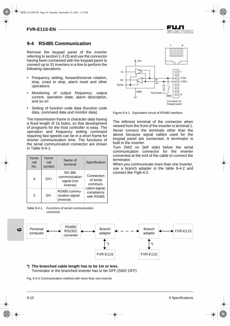
FVR-E11S-EN
9-10 9 Specifications
9
9-4 RS485 Communication
Remove the keypad panel of the inverterreferring to section 1-3 (3) and use the connectorhaving been connected with the keypad panel toconnect up to 31 inverters in a line to perform thefollowing operations.
• Frequency setting, forward/reverse rotation,stop, coast to stop, alarm reset and otheroperations
• Monitoring of output frequency, outputcurrent, operation state, alarm description,and so on
• Setting of function code data (function codedata, command data and monitor data)
The transmission frame is character data havinga fixed length of 16 bytes, so that developmentof programs for the host controller is easy. Theoperation and frequency setting commandrequiring fast speeds can be in a short frame forshorter communication time. The functions ofthe serial communication connector are shownin Table 9-4-1.
Table 9-4-1 Functions of serial communication connector
Figure 9-4-1 Equivalent circuit of RS485 interface
The leftmost terminal of the connector whenviewed from the front of the inverter is terminal 1.Never connect the terminals other than theabove because signal cables used for thekeypad panel are connected. A terminator isbuilt in the inverter.Turn SW2 on (left side) below the serialcommunication connector for the inverterconnected at the end of the cable to connect theterminator.When you communicate more than one inverter,use a branch adapter in the table 9-4-2 andconnect like Fig9-4-2.
Termi-nalNo.
Termi-nal
symbol
Name of terminal
Specification
4 DX+
RS 485 communication
signal (not inverse)
Connectionof serial
communi-cation signal; compliancewith RS4853 DX-
RS485 commu-nication signal (inverse)
Connector for Keypad panel
Terminator
*) The branched cable length has to be 1m or less.Terminator in the branched inverter has to be OFF.(SW2 OFF)
Fig. 9-4-2 Communication method with more than one inverter
Personalcomputer
RS485/RS232Cconverter
Branchadapter
Branchadapter
FVR-E11S
*) *)
FVR-E11S FVR-E11S
MGB_E11S09.FM Page 10 Saturday, September 15, 2001 1:17 PM

9 Specifications 9-11
FVR-E11S-EN
9
9-4-1 Connector and Communication Cable
Use marketed products for the connector, thecommunication cable and branch adapter. Table9-4-2 shows the specification of each of them.
Table 9-4-2 Connector and cable specification
9-4-2 Recommended RS-232C/RS485 Converter
For communications with PCs having anRS232C terminal, the following insulation typeconverter is recommended.
Model: KS485PTI Manufacture: System Sakom
or
Model: I-7520 Manufacture: Spectra
or comparablel.
9-4-3 Remote/local changeover
Operation between according to the frequencysetting and operation commands sent via serialcommunication, and according to the frequencysetting and operation commands set in theinverter main body, can be switched over.The frequency setting and operation commandselection is made as follows, using function H30and remote/local switching.The function of any of the X1 through X5terminals of the inverter main body is changed tobe the LE terminal which is used for remote/localswitching. Any of the functions E01 through E05is used to change the function of X1 to X5terminal. If X1 through X5 terminals are notassigned to the LE terminal, it is always in theremote mode.
Fig. 9-4-3 Command switching block diagram
When X1 through X5 terminals are assignedwith BX, THR and RST functions, the BX, THRand RST functions are activated even in theremote mode according to the inputs to theterminals. RS485 can not make THR ON/OFF.
Item Specification
Connector RJ45 connector
Cable
Cable complying with EIA568 (for 10BASE-T Straight connection)(Max. wiring length: 500m)
Branch adapterMS8-BA-JJJ (SK KOHKI CO., LTD or equivalent.)
Host(PC, PLC)
Frequencysetting
Frequencysetting
Operationcommand
RUN/STOP key / FWD,REV
FWD, REV, X1 to X5
Frequencysetting (keypad panel or analog)
Remote (H30=1,3)
Local or (H30=0,2)
Remote (H30=2,3)
Local or (H30=0,1)
ON: Remote OFF: Local
MGB_E11S09.FM Page 11 Saturday, September 15, 2001 1:17 PM

FVR-E11S-EN
9-12 9 Specifications
9
9-4-4 Communication Protocol
1) Serial communication specification
Table 9-4-3 Serial communication specification
2) Transmission protocol
It is the half duplex communication in thepolling/selecting method. The inverter alwayswaits for a write request (selecting) or a readrequest (polling) from the host. The inverter,when receiving in the wait state a requestframe to the own station from the host,returns a response frame. Upon polling, itreturns data together. In the case ofbroadcasting (selection of all stations in abatch), no response is returned.
Fig. 9-4-2 Communication method with more than oneinverter
Physical levelCompliance with EIA RS-485
(2-wire type)
Number of connected
stations
Host x 1 unit, inverter x 31 units (Station address 1 to 31)
Transmissionspeed
19200, 9600, 4800, 2400, 1200[bit/s]
Synchronizationmethod
Start-stop
Transmissionmethod
Half duplex
Transmissionprotocol
Polling/selecting, broadcast
Character type ASCII 7 bits
Character length Selection between 7 and 8 bits
Transmissiondistance
Max. 500 m
Stop bit Selection between 1 and 2 bits
Frame lengthStandard frame: fixed to 16 bytes, short frame: 8 or 12 bytes
ParitySelection from none, even and odd
Error check method
Checksum, parity, framing error
Polling/selecting
HostRequest
frameRequest
frame
Inverter Response frame
Response interval time (0 to 10 ms)
10ms or longer
Broadcast
HostRequest
frameRequest
frame
Inverter No response frame
10 ms or longer
MGB_E11S09.FM Page 12 Saturday, September 15, 2001 1:17 PM

9 Specifications 9-13
FVR-E11S-EN
9
3) Transmission procedure
1. Set communication functions H30 throughH39.
2. Make communication according to trans-mission frames.
3. If no response returns for one second fromthe inverter upon a frame from the host, retrycommunication. Several retries indicatecertain errors. Make investigation.
4. If no communication is received from the hostfor 30 seconds after the first operationcommand is received, the inverter judges atransmission breakdown error and shutsdown the inverter output, leaving the motor tocoast to stop.
5. After consecutive eight communicationerrors, the inverter output is shut down andthe motor coasts to stop.
4) Host controller transmission procedure
Do not send the next frame unless the responseis returned.
If the inverter does not respond for longer thanthe standard time, timeout should be judged andretry should be performed. If a retry is startedbefore timeout, normal reception may becomeimpossible, so that timeout should be judgedcorrectly. The timeout time is one second in theselecting mode and 0.5 second in the pollingmode. In the retry sequence, send the sameframe again as that sent before no response, orsend a polling (M26: communication errormonitor) frame for reading an error, and checkfor a normal response. (Judge the timeout againduring the check.)
If a normal response is returned, a transienttransmission error due to noise or the like isindicated, and correct communication can becontinued. If retries occur frequently, anyabnormalities are probable. In-depthinvestigation is necessary. If no response isreturned, continue retrying. If there are threeretries, there is some trouble in the hardware orsoftware of the host controller. Terminate thesoftware of the host controller and investigate.
No error code is returned in the case of negativeacknowledgment of a short frame. Judge theerror code using the communication errormonitor (M26) separately.
MGB_E11S09.FM Page 13 Saturday, September 15, 2001 1:17 PM

9-14 9 Specifications
FVR-E11S-EN
9
9-4-5 Standard FrameThe ASCII code character method is employed. A standard frame has a fixed length of 16 bytes.Using optional frames (12 bytes or 8 bytes), the transmission speed can be increased.
Note: Numbers with "H" at the end indicate hexadecimals.
Host
Inverter frame
7(6) 00 Start-of-heading character (SOH) Fixed to 01H.
1 Tens digit of station address (ASCII) Designate a station address of the destinationinverter with 01 to 31 or 99. (ASCII designation of each digit)2 Units digit of station address (ASCII)
3 Enquiry character (ENQ) Fixed to 05H.
4Command type character (ASCII)
E: Reset command, R: Polling (reading), W: Selecting (writing)
5 Function type character (ASCII) "S", "M", "F", "E", "C", "P", "H" or "A" is designated.
6 Tens digit of function number (ASCII) Designate a function number using a two-digitnumber.(Designate each digit of 00 to 46 in ASCII.)7 Units digit of function number (ASCII)
8 Space (ASCII) Fixed to 20H
9 First character of data (ASCII) The data corresponding to the function isconverted into a 4-digit hexadecimal, and eachdigit is designated in ASCII.
10 Second character of data (ASCII)
11 Third character of data (ASCII)
12 Fourth character of data (ASCII)
13 End-of-text character (ETX) Fixed to 03H
14 Upper digit of checksum (ASCII) From tens digit of the station address to ETXare added in a binary and the lower two digitsof it in hexadecimal notation are stored in ASCIIas a checksum.
15 Lower digit of checksum (ASCII)
MGB_E11S09.FM Page 14 Saturday, September 15, 2001 1:17 PM
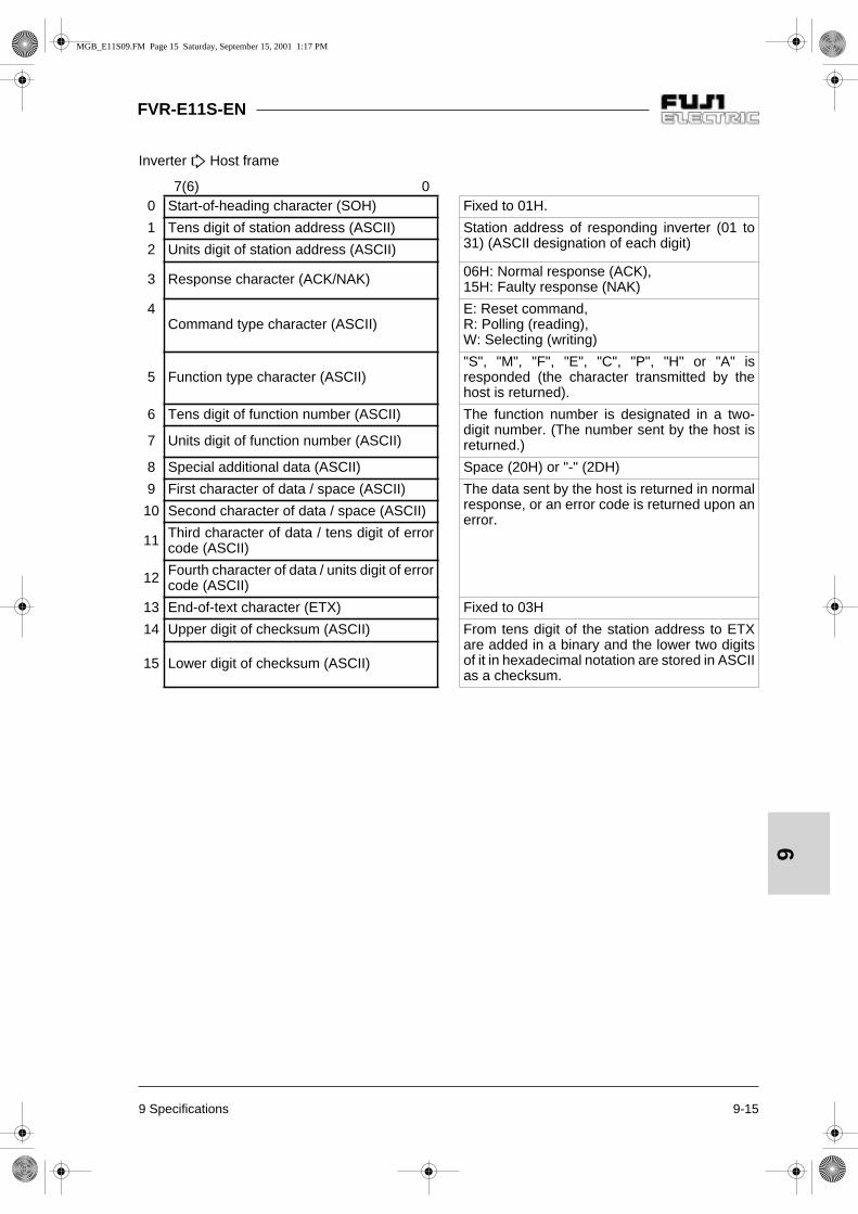
9 Specifications 9-15
FVR-E11S-EN
9
Inverter
Host frame
7(6) 00 Start-of-heading character (SOH) Fixed to 01H.
1 Tens digit of station address (ASCII) Station address of responding inverter (01 to31) (ASCII designation of each digit)2 Units digit of station address (ASCII)
3 Response character (ACK/NAK) 06H: Normal response (ACK), 15H: Faulty response (NAK)
4Command type character (ASCII)
E: Reset command, R: Polling (reading), W: Selecting (writing)
5 Function type character (ASCII)"S", "M", "F", "E", "C", "P", "H" or "A" isresponded (the character transmitted by thehost is returned).
6 Tens digit of function number (ASCII) The function number is designated in a two-digit number. (The number sent by the host isreturned.)7 Units digit of function number (ASCII)
8 Special additional data (ASCII) Space (20H) or "-" (2DH)
9 First character of data / space (ASCII) The data sent by the host is returned in normalresponse, or an error code is returned upon anerror.
10 Second character of data / space (ASCII)
11 Third character of data / tens digit of errorcode (ASCII)
12 Fourth character of data / units digit of errorcode (ASCII)
13 End-of-text character (ETX) Fixed to 03H
14 Upper digit of checksum (ASCII) From tens digit of the station address to ETXare added in a binary and the lower two digitsof it in hexadecimal notation are stored in ASCIIas a checksum.
15 Lower digit of checksum (ASCII)
MGB_E11S09.FM Page 15 Saturday, September 15, 2001 1:17 PM

9-16 9 Specifications
FVR-E11S-EN
9
9-4-6 Short FrameShort frames are prepared for special functions to reduce the data transmission time.
1) Selecting
Host
Inverter frame (selecting)
7(6) 0
Inverter
Host frame (selecting)
7(6) 0
0 Start-of-heading character (SOH) Fixed to 01H.
1 Tens digit of station address (ASCII) Designate a station address of the destinationinverter with 01 to 31 or 99. (Designation of each character in ASCII)2 Units digit of station address (ASCII)
3 Enquiry character (ENQ) Fixed to 05H.
4 Command type character (ASCII) "a", "e", "f" or "m" is designated.
5 First character of data (ASCII) The data corresponding to the function isconverted into a 4-digit hexadecimal, and eachdigit is designated in ASCII.
6 Second character of data (ASCII)
7 Third character of data (ASCII)
8 Fourth character of data (ASCII)
9 End-of-text character (ETX) Fixed to 03H
10 Upper digit of checksum (ASCII) From tens digit of the station address to ETXare added in a binary and the lower two digitsof it in hexadecimal notation are stored in ASCIIas a checksum.
11 Lower digit of checksum (ASCII)
0 Start-of-heading character (SOH) Fixed to 01H.
1 Tens digit of station address (ASCII) Station address of responding inverter (01 to31) (designation of each digit in ASCII)2 Units digit of station address (ASCII)
3 Response character (ACK/NAK) 06H: Normal response (ACK), 15H: Faulty response (NAK)
4 Command type character (ASCII) "a", "e", "f" or "m" sent from the host is returned.
5 End-of-text character (ETX) Fixed to 03H
6 Upper digit of checksum (ASCII) From tens digit of the station address to ETXare added in a binary and the lower two digitsof it in hexadecimal notation are stored in ASCIIas a checksum.
7 Lower digit of checksum (ASCII)
MGB_E11S09.FM Page 16 Saturday, September 15, 2001 1:17 PM

9 Specifications 9-17
FVR-E11S-EN
9
2) Polling
Host
Inverter frame (polling)
7(6) 0
Inverter
Host frame (polling)
7(6) 0
0 Start-of-heading character (SOH) Fixed to 01H.
1 Tens digit of station address (ASCII) Designate the station address of the desti-nation inverter with 01 to 31 or 99. (Designation of each digit in ASCII)2 Units digit of station address (ASCII)
3 Enquiry character (ENQ) Fixed to 05H.
4 Command type character (ASCII) "g", "h", "i", "j" or "k" is designated.
5 End-of-text character (ETX) Fixed to 03H
6 Upper digit of checksum (ASCII) From tens digit of the station address to ETXare added in a binary and the lower two digitsof it in hexadecimal notation are stored in ASCIIas a checksum.
7 Lower digit of checksum (ASCII)
0 Start-of-heading character (SOH)
1 Tens digit of station address (ASCII) Station address of responding inverter (01 to31) (Designation of each digit in ASCII)2 Units digit of station address (ASCII)
3 Response character (ACK/NAK) 06H: Normal response (ACK), 15H: Faulty response (NAK)
4 Command type character (ASCII) "g", "h", "i", "j" or "k" sent from the host isreturned.
5 First character of data / space (ASCII) The data corresponding to the command isconverted into a four digit hexadecimal andeach digit is designated in ASCII.
6 Second character of data / space (ASCII)
7 Third character of data / tens digit of errorcode (ASCII)
8 Fourth character of data / units digit of errorcode (ASCII)
9 End-of-text character (ETX) Fixed to 03H
10 Upper digit of checksum (ASCII) From tens digit of the station address to ETXare added in a binary and the lower two digitsof it in hexadecimal notation are stored in ASCIIas a checksum.
11 Lower digit of checksum (ASCII)
MGB_E11S09.FM Page 17 Saturday, September 15, 2001 1:17 PM

FVR-E11S-EN
9-18 9 Specifications
9
9-4-7 Details of Frame
1) Start-of-heading character (ASCII; SOH)
01H in binary.
2) Tens digit and units digit of station address
Two ASCII characters expressing a decimalstation address between 1 and 31.Example:Station address 1: Tens digit of station address: ASCII "0", unitsdigit of station address: ASCII "1"Station address 31: Tens digit of station address: ASCII "3", unitsdigit of station address: ASCII "1"
3) Enquiry character (ASCII; ENQ)
05H in binary.
4) Response character (ASCII; ACK/NAK)
The inverter sets ACK (06H) to recognize arequest.NAK (15H) is set when the request from thehost includes a logical error.
5) Command type character
In a standard frame, set "R" in ASCII for apolling (reading) request, or set "W" in ASCIIfor a selecting (writing) request. Set "E" inASCII for a resetting command. Only theupper case characters are valid.In a short frame, the function is directlydesignated using a command type character.Refer to (3) Short Frame in section 9-4-11Function Code List for details.
6) Function type character and tens digit andunits digit of function number
A request function is designated in threecharacters. Refer to section 9-4-11 FunctionCode List for details.
7) Special additional data
This is normally a space (20H). In a responseframe issued by an inverter to request forfrequency monitor (M09), a minus sign is setin ASCII during reverse rotation output.
8) Data
In a selecting (writing) request frame sentfrom the host to an inverter, designate writingdata. Refer to section 9-4-10 Data Type. In apolling (reading) frame, set space or arbitraryletter or number character. in a selectingresponse frame sent from an inverter to thehost, data "0000" or an error code iscontained, and in a polling frame, data or anerror code is contained.
9) End-of-text character (ASCII; ETX)
03H in binary.
10)Upper digit and lower digit of checksum
A binary sum of all the characters from tensdigit of the station address to the end-of-textcharacter is obtained and the lower two digitsof it in hexadecimal notation are expressed inASCII codes. Set in the upper case.Example: When the binary sum is "17EH"
The upper digit of the checksum is "7" inASCII. The lower digit of the checksum is "E"in ASCII.
9-4-8 BroadcastingAn operation command or frequency commanddestined to station address "99" is received andprocessed by all the inverters as broadcasting.However, no response is issued by the inverters.
MGB_E11S09.FM Page 18 Saturday, September 15, 2001 1:17 PM

9 Specifications 9-19
FVR-E11S-EN
9
9-4-9 Communication Error CodeThe inverter detects the following errors. Theerror code is in hexadecimal notation.
Table 9-4-4 Communication Error Code
The inverter does not return NAK in response toerrors 47 through 49 above. It issues noresponse.In the case of errors 4A through 50, an NAKresponse with an NAK code in the responsecharacter field and the two digit hexadecimalerror code in the data field is returned.The latest error can be referred to using thetransmission error end code monitor (M26).
9-4-10 Data Type1) In the case of value data
16 bit data is expressed in a hexadecimal andset using four ASCII codes. Concretelyspeaking, the data is between "0000" and"FFFF".Decimal fractions are weighted into integers.Refer to the corresponding section because theweight varies according to each piece of functiondata. In some functions, the negative value isexpressed in two's complement.The bit data is converted into the hexadecimaland expressed.The acknowledgement sent from the inverter inresponse to a selecting (writing) request is thewriting data. In the negative acknowledgement,the error code is returned in two hexadecimalcharacters.Set "0000" or an arbitrary letters and numbers inthe data to be transmitted to the inverter in apolling (reading) frame.Example: Frequency data, weight 100 times120.00Hz 120 x 100=12000=2EE0HThe data is "2" in ASCII, "E" in ASCII, "E" inASCII and "0" in ASCII in order from the firstcharacter to the fourth character.Acceleration time data, weight 10 times6.5 sec: 6.5 x 10 = 65 = 41HThe data is "0" in ASCII, "0" in ASCII, "4" inASCII and "1" in ASCII in order from the firstcharacter to the fourth character.
2) In the case of bit data
For bit type data requested by S06, M13 or otherfunctions, the bit data is expressed inhexadecimal notation and each digit istransmitted in ASCII codes.Example: S06 with FWD (bit 0) ON, X1 (bit 2)ON, and X3 (bit 4) ONBit data = 0000 0000 0001 0101
0015H (Hexadecimal)
30H 30H 31H 35H (ASCII)
Errorcode
(hexa-decimal)
Name of error
Description
47HChecksum
error
The checksum of the frame sent to the own station is in discrepancy.
48H Parity errorThe parity is in discrepancy.
49H OthersReception error other than above (framing, overrun)
4AHFormaterror
The enquiry character or the end-of-text character in the transmitted frame is in an incorrect position.
4BHCommand
error
A code other than designated commands (standard and option) is sent.
4EHFunction
code errorA request for an unknown function code is issued.
4FHWrite
disable
A write prohibited function or in-operation write prohibited function is written during operation.
50H Data errorData exceeding the standard range is written.
MGB_E11S09.FM Page 19 Saturday, September 15, 2001 1:17 PM
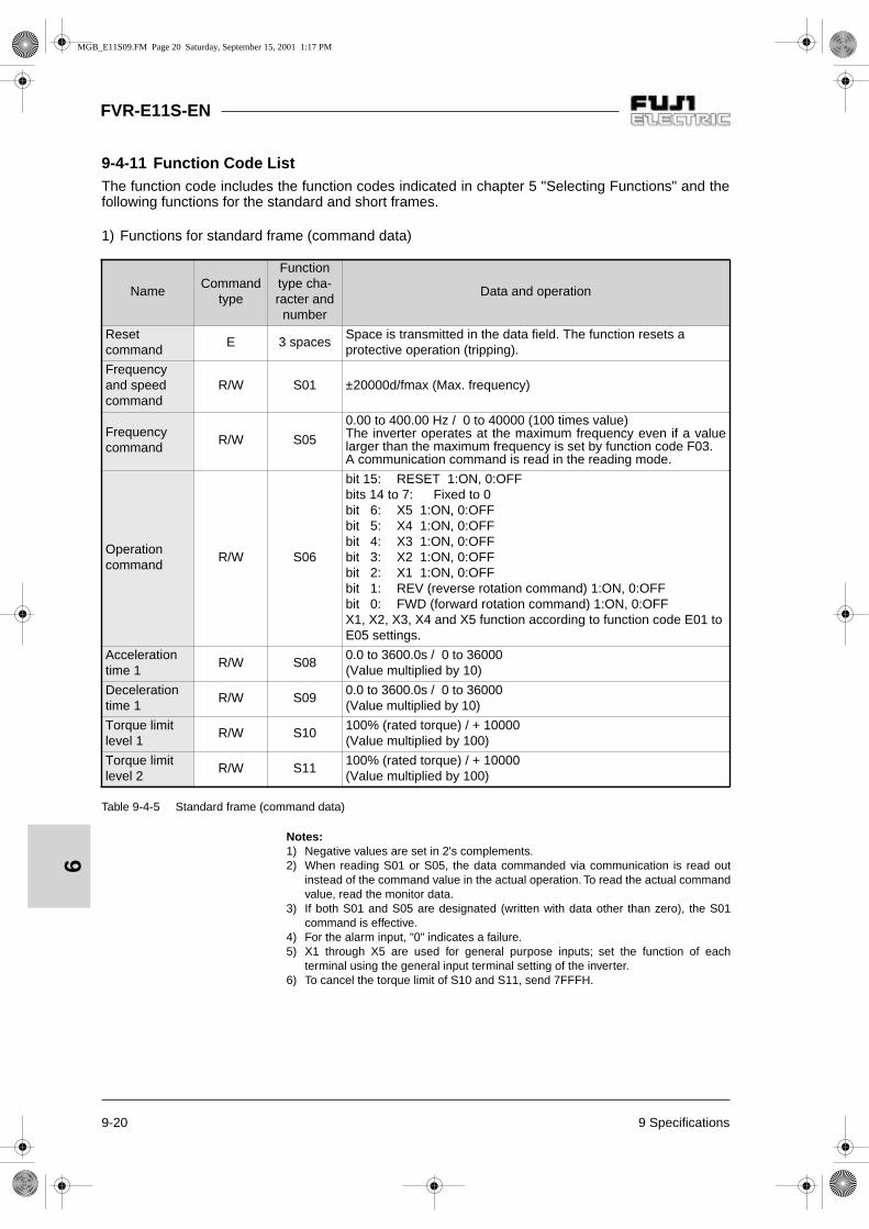
9-20 9 Specifications
FVR-E11S-EN
9
9-4-11 Function Code ListThe function code includes the function codes indicated in chapter 5 "Selecting Functions" and thefollowing functions for the standard and short frames.
1) Functions for standard frame (command data)
Table 9-4-5 Standard frame (command data)
NameCommand
type
Functiontype cha-racter and number
Data and operation
Resetcommand
E 3 spacesSpace is transmitted in the data field. The function resets a protective operation (tripping).
Frequencyand speed command
R/W S01 ±20000d/fmax (Max. frequency)
Frequencycommand
R/W S05
0.00 to 400.00 Hz / 0 to 40000 (100 times value)The inverter operates at the maximum frequency even if a valuelarger than the maximum frequency is set by function code F03.A communication command is read in the reading mode.
Operationcommand
R/W S06
bit 15: RESET 1:ON, 0:OFFbits 14 to 7: Fixed to 0bit 6: X5 1:ON, 0:OFFbit 5: X4 1:ON, 0:OFFbit 4: X3 1:ON, 0:OFFbit 3: X2 1:ON, 0:OFFbit 2: X1 1:ON, 0:OFFbit 1: REV (reverse rotation command) 1:ON, 0:OFFbit 0: FWD (forward rotation command) 1:ON, 0:OFFX1, X2, X3, X4 and X5 function according to function code E01 to E05 settings.
Accelerationtime 1
R/W S080.0 to 3600.0s / 0 to 36000 (Value multiplied by 10)
Decelerationtime 1
R/W S090.0 to 3600.0s / 0 to 36000 (Value multiplied by 10)
Torque limit level 1
R/W S10100% (rated torque) / + 10000 (Value multiplied by 100)
Torque limit level 2
R/W S11100% (rated torque) / + 10000 (Value multiplied by 100)
Notes:1) Negative values are set in 2's complements.2) When reading S01 or S05, the data commanded via communication is read out
instead of the command value in the actual operation. To read the actual commandvalue, read the monitor data.
3) If both S01 and S05 are designated (written with data other than zero), the S01command is effective.
4) For the alarm input, "0" indicates a failure. 5) X1 through X5 are used for general purpose inputs; set the function of each
terminal using the general input terminal setting of the inverter.6) To cancel the torque limit of S10 and S11, send 7FFFH.
MGB_E11S09.FM Page 20 Saturday, September 15, 2001 1:17 PM

9 Specifications 9-21
FVR-E11S-EN
9
2) Functions for standard frame (monitor data)
NameCommand
typecharacter
Functiontype cha-racter and number
Data and operation
Frequency(Final value)
R M01 ±20000d/fmax (Max. frequency)
Frequencycommandvalue
R M05100=1.00Hz (Value multiplied by 100)The current frequency setting is returned.
Calculatedtorque value
R M07 100% (rated torque) / ±10000 (value multiplied by 100).
Torquecurrent
R M08 100% (rated current) / ±10000 (value multiplied by 100).
Outputfrequency
R M09100=1.00Hz(Value multiplied by 100; special additional data: sign)The current output frequency is returned.
Motor output (powerconsumption)
R M10100% (rated output) / ±10000 (value multiplied by 100)
Output current R M11100 = 1% of rated inverter currentThe current output frequency is returned in the ratio of the rated current.
Output voltage R M12 10=1V
Operationcommand
R M13
bit 15: RESET 1:ON, 0:OFFbits 14 to 7: Fixed to 0bit 6: X5 1:ON, 0:OFFbit 5: X4 1:ON, 0:OFFbit 4: X3 1:ON, 0:OFFbit 3: X2 1:ON, 0:OFFbit 2: X1 1:ON, 0:OFFbit 1: REV (reverse rotation command) 1:ON, 0:OFFbit 0: FWD (forward rotation command) 1:ON, 0:OFFThe final command value including the state of the actual control terminal of the inverter is returned.
Operationstatus
R M14
bit 15: Function code data being writtenbit 12: 1: Communication validbit 11: 1: Batch failure (tripping)bit 10: 1: During decelerationbit 9: 1: During accelerationbit 8: 1: Current limit operationbit 7: 1: Voltage limit operationbit 6: 1: Torque limit operationbit 5: 1: DC link voltage establishedbit 4: 1: During brakingbit 3: 1: During output shutoffbit 2: 1: During DC brakingbit 1: 1: During reverse rotationbit 0: 1: During forward rotation
Generalpurposeoutputterminal
R M15bit 1: Y2; active upon "1"bit 0: Y1; active upon "1"
MGB_E11S09.FM Page 21 Saturday, September 15, 2001 1:17 PM

9-22 9 Specifications
FVR-E11S-EN
9Table 9-4-6 Standard frame (monitor data)
NameCommand
typecharacter
Functiontype cha-racter and number
Data and operation
Failuredescription;current one
R M16
Refer to (4) Alarm display data
Failuredescription;previous one
R M17
Failuredescription;one before previous one
R M18
Failuredescription;one before two previous ones
R M19
Totaloperation time
R M20 0 to 65535 / 0 to 65535 hours
DC link voltagemonitor
R M210 to 500 / 0 to 500V (200V class)0 to 1000 / 0 to 1000V (400V class)
Function code R M234112H = E11S single-phase 200V4113H = E11S 3-phase 200V4114H = E11S 3-phase 400V
Capacity code R M24 1=0.01kW
ROM version R M250 to 99: Standard, > 100: Non-standard
Transmissionerror handling code
R M26Refer to section 9-4-9. The latest error is returned. The communication error is initialized when the power is turned off.
Main circuit capacitor life
R M46 1=0.1%
Cooling fan life R M48 1 = 1 hour
Note:1) Output frequency monitoring (M09, M35) adds an ASCII code for forward rotation
(space), reverse rotation (minus) and stop (space) as direction of rotation data,and handled as 5-byte data.
MGB_E11S09.FM Page 22 Saturday, September 15, 2001 1:17 PM

9 Specifications 9-23
FVR-E11S-EN
9
3) Functions for short frame
Table 9-4-7 Short frame
4) Alarm display data
The failure description (alarm description) is as shown in the table below. The failure code is in thehexadecimal notation.
FunctionCommand type
characterData direction
Data range; transmission data /
actual data
Change during operation
Frequencycommand
a Selecting Same as S01 O
Frequencycommand
e Selecting Same as S05 O
Operationcommand
f Selecting Same as S06 O
Reset command m Selecting 4 spaces –
Calculated torque value monitor
h Polling Same as M07 –
Torque current monitor
l Polling Same as M08 –
Output frequency monitor
j PollingSame as M09; no sign is
attached.–
Operation state monitor
k Polling Same as M14 –
Table 9-4-8 Failure description
Failurecode
DescriptionIndicationon panel
0000 No alarm ---
0001Overcurrent,during acceleration
OC1
0002Overcurrent,during deceleration
OC2
0003Overcurrent, during constant speed operation
OC3
0006Overvoltage,during acceleration
OU1
0007Overvoltage,during deceleration
OU2
0008Overvoltage, during constant speed operation
OU3
000A Undervoltage LU
000B Input phase loss Lin
Failurecode
DescriptionIndicationon panel
0011 Heat sink overheat OH1
0012 External alarm OH2
0016 Braking resistor overheat dbH
0017 Motor 1 overload OL1
0018 Motor 2 overload OL2
0019 Inverter overload OLU
001F Memory error Er1
0020Keypad panel communication error
Er2
0021 CPU error Er3
0025 Output phase loss error Er7
0026RS485 communication error
Er8
MGB_E11S09.FM Page 23 Saturday, September 15, 2001 1:17 PM

FVR-E11S-EN
9-24 9 Specifications
9
9-4-12 Data formatThe data format of each piece of function codedata of the inverter is defined here.Prepare data according to the format numberedin the data format for each function code. (Referto section 5-1 Function Setting List and section9-4-11 Function Code List for the data format.)The data field of the transmission frame exceptfor data format 10 consists of a 4-digit ASCIIcode converted from a 4-digit hexadecimal dataas shown in the figure below. For details of eachformat, refer to the following data formats (1)through (11).
1) Data format 0
16-bit binary code, least increment 1, positivevalue only.
Example:In the case that F15: (frequency limiter, upperlimit) = 60 Hz
60 x 1 = 60 (dec.) = 003C (hex.), hence: 003C
2) Data format 1
16-bit binary code, least increment 1,positive/negative valueThe negative value is expressed in 2'scomplement. -1 FFFF (hex.)
Example:In the case that F18: (bias frequency) = -20 Hz
-20 x 1 = -20 (dec.) = FFEC (hex.), hence:FFEC
3) Data format 2
16-bit binary code, least increment 0.1,positive value only
Example:In the case that F17: (gain frequency settingsignal) = 100.0%
100.0 x 10 = 1000 (dec.) = 03E8 (hex.),hence: 03E8
4) Data format 3
16-bit binary code, least increment 0.1,positive/negative value
The negative value is expressed in 2'scomplement. -1 FFFF (hex.)
Example:In the case that C31: (analog input offsetadjustment, terminal 12) = -5.0%
-5.0 x 10 = -50 (dec.) = FFCE (2's complement)
5) Data format 4
16-bit binary code, least increment 0.01,positive value only
Example:In the case that C05: (multistep frequency 1)= 50.25 Hz
50.25 x 100 = 5025 (dec.) = 13A1 (hex.),hence: 13A1
15 14 13 12 11 10 9 8 7 6 5 4 3 2 1 0
4-digit hexadecimal data 4-digit ASCII code
0 0 3 C
F F E C
0 3 E 8
F F C E
1 3 A 1
MGB_E11S09.FM Page 24 Saturday, September 15, 2001 1:17 PM
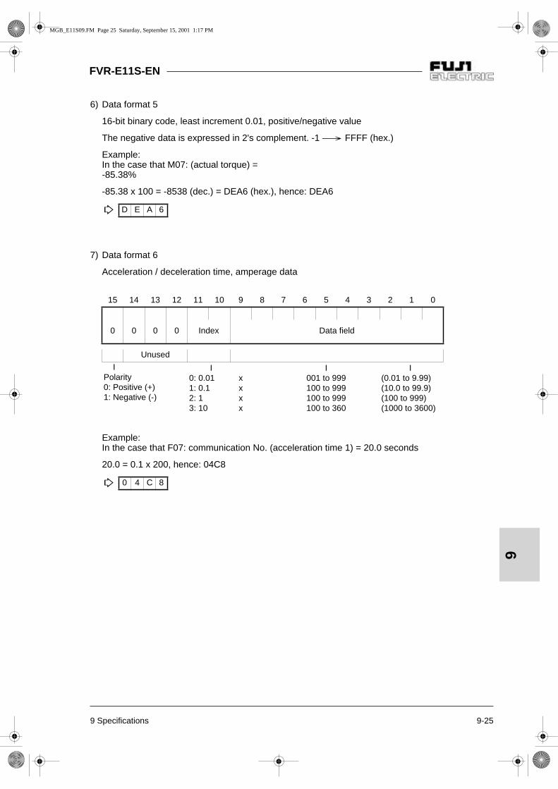
9 Specifications 9-25
FVR-E11S-EN
9
6) Data format 5
16-bit binary code, least increment 0.01, positive/negative value
The negative data is expressed in 2's complement. -1 FFFF (hex.)
Example:In the case that M07: (actual torque) = -85.38%
-85.38 x 100 = -8538 (dec.) = DEA6 (hex.), hence: DEA6
7) Data format 6
Acceleration / deceleration time, amperage data
Example:In the case that F07: communication No. (acceleration time 1) = 20.0 seconds
20.0 = 0.1 x 200, hence: 04C8
D E A 6
15 14 13 12 11 10 9 8 7 6 5 4 3 2 1 0
0 0 0 0 Index Data field
Unused
IPolarity0: Positive (+)1: Negative (-)
I0: 0.011: 0.12: 13: 10
xxxx
I001 to 999100 to 999100 to 999100 to 360
I(0.01 to 9.99)(10.0 to 99.9)(100 to 999)(1000 to 3600)
0 4 C 8
MGB_E11S09.FM Page 25 Saturday, September 15, 2001 1:17 PM

9-26 9 Specifications
FVR-E11S-EN
9
8) Data format 8
Operation command
I
FWD: forward rotation commandREV: reverse rotation command
(All bits: "1" when turned on)
Example:In the case that M13: (operation command) = 0000 0000 0100 0101 (bin.): FWD, X1, X5 = ON
M13 = 0045 (hex.), hence: 0045
9) Data format 9
General-purpose output terminal
I
General purpose output
(All bits: "1" when turned on)
Example:In the case that M15: (general-purpose output terminal) = 0000 0000 0000 0001 (bin.): Y1 = ON
M15 = 0001 (hex.), hence: 0001
15 14 13 12 11 10 9 8 7 6 5 4 3 2 1 0
Res
et
0 0 0 0 0 0 0 0 X5 X4 X3 X2 X1
RE
V
FW
D
Unused General purpose input
0 0 4 5
15 14 13 12 11 10 9 8 7 6 5 4 3 2 1 0
0 0 0 0 0 0 0 0 0 0 0 0 0 0 Y2 Y1
Unused
0 0 0 1
MGB_E11S09.FM Page 26 Saturday, September 15, 2001 1:17 PM

9 Specifications 9-27
FVR-E11S-EN
9
10)Data format 10
Operation state
(All bits: "1" when turned on or active)
FWD: During forward rotationREV: During reverse rotationEXT: During DC brakingINT: Inverter shutdownBRK: During brakingNUV: DC link establishedTL: Torque limit operationVL: Voltage limit operationIL: Current limit operationACC: During accelerationDEC: During decelerationALM: Batch alarmRL: Transmission valid/invalidBUSY: During data writing (processing)
Example:Omitted (The monitoring method is similar to format 8.)
11)Data format 11
16-bit binary code, least increment 0.01, positive/negative data (5-byte ASCII code)
Example:In the case that M09 (output frequency) = +60.00 Hz
60.00 x 100 = 6000 (dec.) = 1770 (hex.), hence: 1770
Positive data is handled in a 4-byte ASCII code similarly to data format 0.
In the case that M09 (output frequency) = -60.00 Hz
60.00 x 100 = 6000 (dec.) = 1770 (hex.). An ASCII code of the minus sign is added at the top.: -1770
15 14 13 12 11 10 9 8 7 6 5 4 3 2 1 0
BU
SY
– – RL
ALM
DE
C
AC
C
IL VL
TL
NU
V
BR
K
INT
EX
T
RE
V
FW
D19 18 17 16 15 14 13 12 11 10 9 8 7 6 5 4 3 2 1 0
ASCII code (of minus sign)
4-digit hexadecimal data 4-digit ASCII code
1 7 7 0
- 1 7 7 0
MGB_E11S09.FM Page 27 Saturday, September 15, 2001 1:17 PM
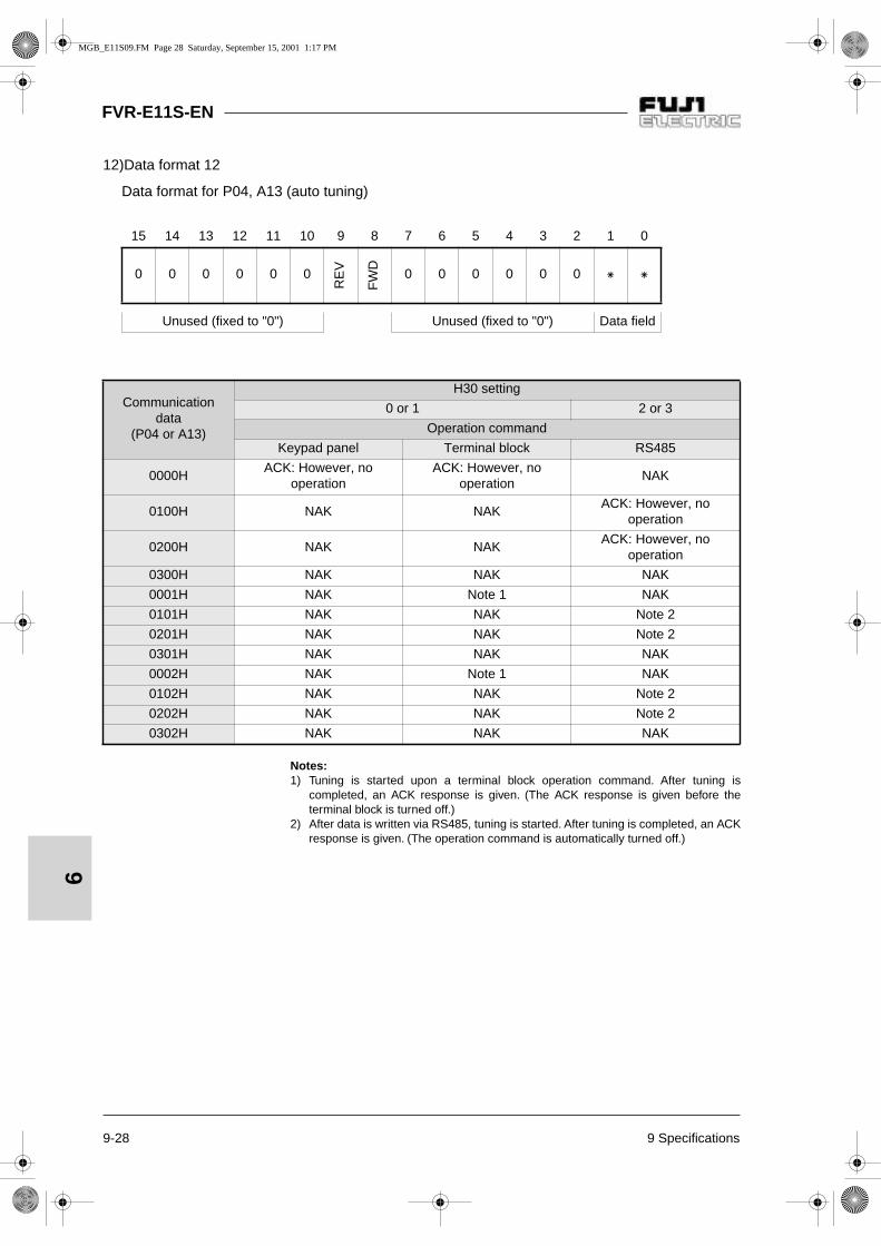
9-28 9 Specifications
FVR-E11S-EN
9
12)Data format 12
Data format for P04, A13 (auto tuning)
15 14 13 12 11 10 9 8 7 6 5 4 3 2 1 0
0 0 0 0 0 0
RE
V
FW
D
0 0 0 0 0 0
Unused (fixed to "0") Unused (fixed to "0") Data field
Communicationdata
(P04 or A13)
H30 setting
0 or 1 2 or 3
Operation command
Keypad panel Terminal block RS485
0000HACK: However, no
operationACK: However, no
operationNAK
0100H NAK NAKACK: However, no
operation
0200H NAK NAKACK: However, no
operation
0300H NAK NAK NAK
0001H NAK Note 1 NAK
0101H NAK NAK Note 2
0201H NAK NAK Note 2
0301H NAK NAK NAK
0002H NAK Note 1 NAK
0102H NAK NAK Note 2
0202H NAK NAK Note 2
0302H NAK NAK NAK
Notes:1) Tuning is started upon a terminal block operation command. After tuning is
completed, an ACK response is given. (The ACK response is given before theterminal block is turned off.)
2) After data is written via RS485, tuning is started. After tuning is completed, an ACKresponse is given. (The operation command is automatically turned off.)
MGB_E11S09.FM Page 28 Saturday, September 15, 2001 1:17 PM

10 Options 10-1
FVR-E11S-EN
10
10 Options
10-1 External options
Table 10-1-1 External options
Name Explanation
Molded case circuit breaker
The molded case circuit breaker (MCCB) is connected for theprotection of the main circuit wiring up to the inverter and for turningthe power on and off. The rated current or the rated interruptingcapacity varies according to the power supply specifications.
DC reactor (DCR)
Connect in the following cases.1) When the power supply transformer capacity exceeds 500 kVA.
2) When a thyristor load is connected to the same power supply orwhen the capacitor for power factor improvement is turned on oroff.
3) When the unbalance rate between phases of the source voltageexceeds 2%.
4) To reduce the harmonic current in the input. The input powerfactor can be improved to 0.9 to 0.95.
Magnetic contactor (MC)The inverter can be operated without an electromagnetic contactor.Connect one to turn the power off for the safety after the protectivefunction of the inverter is activated.
Surge absorber
Connect to suppress the surge generated when the electromagneticcontactors, control relays or other exciting coils are opened orclosed.S2-A-0 (for electromagnetic contactors), S1-B-0 (for miniaturecontrol relays)
Reactor for radio noise reduction
Use for noise reduction when electric noise interference is caused toradios or electronic devices near the inverter.
Frequency setting unit Connect to set the frequency from the control circuit terminals usingthe inverter power supply.
(Max. Voltage [V]) - (Min. Voltage [V])
(Average voltage of three phases [V])
Unbalance rate between phases [%] = x 67 %
MGB_E11S10.FM Page 1 Saturday, September 15, 2001 1:18 PM

11-1 11 Applicable reactor
FVR-E11S-EN
11
G
L1/R
L3/T
G
U
V
W
G
P1
P(+)
M3
P1
P(+)
L1/L
L2/N
L2/S
11 Applicable reactor
The DC reactors are recommended to reduce inverter input harmonic current or to correct inverterinput power factor.
Table 11-1-1 List of applicable reactor
Connection method
Three-phase power supplyMotor
Single-phase power supply
DC reactor
Figure 11-1-1 Connection method of DC reactor (DCR)
Applicable inverter model DC reactor (DCR)
FVR0.1E11S-7EN DCR2-0.2
FVR0.2E11S-7EN DCR2-0.4
FVR0.4E11S-7EN DCR2-0.75
FVR0.75E11S-7EN DCR2-1.5
FVR1.5E11S-7EN DCR2-2.2
FVR2.2E11S-7EN DCR2-3.7
FVR0.4E11S-4EN DCR4-0.4
FVR0.75E11S-4EN DCR4-0.75
FVR1.5E11S-4EN DCR4-1.5
FVR2.2E11S-4EN DCR4-2.2
FVR4.0E11S-4EN DCR4-3.7
FVR5.5E11S-4EN DCR4-5.5
FVR7.5E11S-4EN DCR4-7.5
MGB_E11S11.FM Page 1 Saturday, September 15, 2001 1:19 PM

12 Electromagnetic Compatibility (EMC) 12-1
FVR-E11S-EN
12
12 Electromagnetic Compatibility (EMC)
12-1 General
In accordance with the provisions described inthe European Commission Guidelines Docu-ment on Council Directive 89/336/EEC,FujiElectric Co., Ltd. has chosen to classify the FVR-E11S range of inverters as "Complex Compo-nents".Classification as a "Complex Components"allows a product to be treated as an "apparatus",and thus permits compliance with the essentialrequirements of the EMC Directive to bedemonstrated to both an integrator of FVRinverters and to his customer or the installer andthe user.FVR inverters is supplied ’CE-marked’,signifying compliance with EC Directive 89/336/EEC when fitted with specified filter unitsinstalled and earthed in accordance with thissheet.This Specification requires the following perfor-mance criteria to be met.
EMC product standard EN61800-3/1997
Immunity: Second environment (Industrial environment)
Emission: First environment(Domestic environment)
Finally, it is customer’s responsibility tocheck whether the equipment conforms toEMC directive.
12-2 Recommended Installation Instructions
It is necessary that to conformed to EMC Direc-tive, these instructions must be followed. Follow the usual safety procedures when wor-king with electrical equipment. All electrical con-nections to the filter, Inverter and motor must bemade by a qualified electrical technician.
1) Use the correct filter according to Table 12-2-1.
2) Install the Inverter and filter in the electricallyshielded metal wiring cabinet.
3) The back panel of the wiring cabinet of boardshould be prepared for the mounting dimensi-ons of the filter. Care should be taken to re-move any paint etc. from the mounting holesand face area of the panel. This will ensurethe best possible earthing of the filter.
4) Use the screened cable for the control, motorand other main wiring which are connected tothe inverter, and these screens should be se-curely earthed.
5) It is important that all wire lengths are kept asshort as possible and that incoming mainsand outgoing motor cables are kept well se-parated.
"To minimize the conducted radio disturb-ance in the power distribution system, thelength of the motor-cable should be as shortas possible."
MGB_E11S12.FM Page 1 Saturday, September 15, 2001 1:19 PM

FVR-E11S-EN
12-2 12 Electromagnetic Compatibility (EMC)
12
12-3 The harmonics restriction in EU
This inverter is professional use only and it isprohibited to connect this inverter to public lowvoltage power supply by standards (EN61800-3(+A11) and EN61000-3-2(+A14)) concerningthe harmonics restriction.The target inverters of the harmonics restrictionare models of up to active input power 1kW atpresent and Fuji inverter types, the standardsapply to, are as follows.
FVR0.1C11S-7ENFVR0.2C11S-7ENFVR0.4C11S-7ENFVR0.75C11S-7ENFVR0.1E11S-7ENFVR0.2E11S-7ENFVR0.4E11S-7ENFVR0.75E11S-7ENFVR0.4E11S-4ENFVR0.75E11S-4EN
12-4 RCD (Residual-current-operated protective device) for the single-phase 200V input inverter
In case of using RCD, as for the single-phase200V input inverter (FVR***-7EN), RCD of type Aor RCD of type B is allowed on the power supplyside of the EE (Electric equipment).
Fig. 12-4-1 Installation of RCD
RCD Inverter Motor
Type A or
Type B
Three-phase power supply
Single-phase power supply
Fig. 12-2-1 Recommended installation
M3
W
V
U
L3
L2
L1
G
L3'
L2'
L1'
G
L3/T
L2/S
L1/R
GG
RFI filter InverterMCCB or ELCB Screened motor cable
Metal wiring cabinet
Screening must be electri-cally continuous and earthedat the cabinet and the motor.
M3
W
V
U
N
L
G
N'
L'
G
L2/N
L1/L
GG
RFI filter InverterMCCB or ELCB Screened motor cable
Metal wiring cabinet
Screening must be electri-cally continuous and earthedat the cabinet and the motor.
MGB_E11S12.FM Page 2 Saturday, September 15, 2001 1:19 PM

12 Electromagnetic Compatibility (EMC) 12-3
FVR-E11S-EN
12
Table 12-2-1 RFI filters
Note: For detail, refer to the instruction manual that came with the RFI filters.Maximum motor cable length: 10m (EN55011 Class B), 50m (EN55011 Class A)
Fig. 12-2-2
AppliedInverter
Filter TypeRated
Current [A]
Max.Rated
Voltage
Max.LeakageCurrent
[mA]
Dimensions [mm]Mass[kg]W W1 H H1 D
FVR0.1E11S-7ENFVR0.2E11S-7ENFVR0.4E11S-7EN
EFL-0.4E11-7 6.5
1-ph240 Vac
39.7 71 55 189 178 50 0.7
FVR0.75E11S-7EN EFL-0.75E11-7 18 39.7 110 80 191 165 50 1.7
FVR1.5E11S-7ENFVR2.2E11S-7EN
EFL-2.2E11-7 29 39.7 174 145 191 165 76 2.8
FVR0.4E11S-4ENFVR0.75E11S-4EN
EFL-0.75E11-4 5
3-ph480 Vac
77 110 80 191 165 41 0.75
FVR1.5E11S-4ENFVR2.2E11S-4EN
EFL-2.2E11-4 10 80.5 110 80 191 165 41 0.95
FVR4.0E11S-4EN EFL-4.0E11-4 15 80.5 174 145 191 165 46 1.35
FVR5.5E11S-4ENFVR7.5E11S-4EN
EFL-7.5E11-4 30 176 182 145 278 252 56 2.00
LINE
LOAD
The view can vary dependent on the filter type.
MGB_E11S12.FM Page 3 Saturday, September 15, 2001 1:19 PM

European headquarterFuji Electric GmbH Lyoner Str. 26 D-60528 Frankfurt am Main Tel.: +49-69-66 90 29-0 Fax: +49-69-66 90 29-58e-mail: [email protected]: http://www.fujielectric.de
GermanyFuji Electric GmbH Fuji Electric GmbH Fuji Electric GmbHHead of sales Sales area Südwest Sales area WestLyoner Str. 26 Drosselweg 3 Dolmanstr. 4660528 Frankfurt am Main 72666 Neckartailfingen 51427 Bergisch GladbachTel.: +49-69-66 90 29-47 Tel.: +49-71 27-92 28 00 Tel.: +49-22 04-96 03 88Fax: +49-69-66 90 29-58 Fax: +49-71 27-92 28 01 Fax: +49-22 04-96 03 [email protected] [email protected] [email protected]
Switzerland United Kingdom SpainFuji Electric GmbH Fuji Electric GmbH Fuji Electric GmbHZweigniederlassung UK Branch Parc Technòlògic delAltenrhein 2, Chalkhill Road Vallés-Nr. 023IG-Park Hammersmith E-08290 Cerdanyola, CH-9423 Altenrhein London W6 8DW BarcelonaTel.: +41-71-8 58 29 49 Tel.: +44-208 233 11 66 Tel.: +34-93-58 24-3 33/5Fax: +41-71-8 58 29 40 Fax: +44-208 233 11 40 Fax: +34-93-58 24-3 [email protected] [email protected] [email protected]
Specialised dealer:
MGB-E11EN01.09
Subject to technical changes
Solutions for Drives
MGB_E11S14.FM Page 1 Thursday, October 4, 2001 11:33 AM