Embed Size (px)
Citation preview
MMS streaming protocol Website http://sdp.ppona.com/
SDP Team: “putting the MMS jigsaw puzzle together piece by piece”
UPDATE HISTORY Update 07.Dec.2003 Command 06 to client - authentication result flags updated. Command 0A to client - possible seeking rate added. Command 15 to server - typo error corrected, pre-roll time now in milliseconds not seconds. Command 1A to client - value CommandLevel for NTLM updated. Command 1A to server - encryption types list updated. Command 28 to server - possible seeking rate added. Command 33 to server - stream switch structure updated. Section: ‘Switch elements or Stream Ids’ updated text (see command 33 to server). Update 04.July.2003 (we changed the date format!) Command 06 to client – broadcast flags data updated, also result flags data updated. Command 07 to server – command structure update with ‘max stream time’ new info added. Section ‘About Error Codes and Command Level Values’ Prefix 1 data (client to server) updated. Section ‘MMS Pre Headers’ – UDP sequence / TCP flag (for TCP streaming) data updated. Update 01.04.03 Page numbers included for all documents. Section ‘MMS command packet header’ updated. Command 02 to client updated. Command 06 to client updated. Command 1A to client updated for NTLM use. Command 1A to server updated. Command 20 to client updated. Command 33 to server updated. Section ‘MMS Command Protocol State Sequences’ updated for NTLM use. Section ‘MMS Media and Header Object Packet Pre headers’ updated. Update 12.01.03 Website URL changed to main site address. Document now also available in PDF format. Update 16.12.02 Section ‘MMS Pre Headers’ has been updated. Update 06.11.02 Command 33 to server updated. Update 31.10.02 New MMS command 20 to client – command added. Command 01 to client updated. Command 05 to client updated. Command 07 to server updated. Command 11 to client updated. Command 15 to server updated.
1
Update 01.10.02 Command 01 to Client – structure updated Command 02 to Server – data updated Command 02 to Client – data updated Command 05 to Client – structure updated Command 06 to Client – data added at end Command 07 to Server – structure updated Command 09 to Server – data updated Command 0d to Server – data updated Command 11 to Server – data updated Command 1A to Server – data updated Section ‘MMS Pre Headers’ the whole section was updated, new data added Section ‘MMS Command Protocol State Sequences’ end details updated Update 30.09.02 New section added : ‘IEEE 754-1985 double precision values’ All MMS functions in this document using this 8 byte double precision value have been updated, including the MMS command header section. Command 05 to Client updated Command 06 to Client updated Command 07 to Server updated Update 12.09.02 New section added : ‘MMS flags’ to hopefully explain further how they work. Command 01 to server – text changed. Command 02 to server and 02 to client – text changed. Command 05 to client - basic structure now included. Command 06 to client – structure extended Command 11 to client – extra info added, now includes ‘packet pair’ Command 18 to server - updated Section ‘MMS command protocol state sequences’ has been updated Section ‘MMS pre-headers’ New item ‘MMS timing packet pairs’ added Section ‘ASF UDP/TCP packet re-syncronisation’ updated. Section ‘Time codes, media packets and ASF headers for live broadcasts’ extended with new summary. Update 20.06.02 Document error correction in section: ‘MMS Pre Headers’ sub section : ‘MMS Header Pre-Headers’ The line did read “not including the pre header field” And has been corrected and now reads “including the pre header field length”. Update 04.05.02 New section added ‘MMS Proxy Servers’ - an overall explanation. Section ‘Known MMS commands’ – Client to Server command 01 updated Section ‘Known MMS commands’ – A new command added; server to client 0A. Update 24 04.02 All references to ‘Session ID’ have been replaced with a new value ‘PacketIDType’ Update 23.04.02 Section ‘known MMS commands’ new data added to command 06 to client Change made to command 07 to server (packet ID type) Change made to command 15 to server (packet ID type) Section ‘About error codes…’ some inaccurate text has been removed
2
Update 22.04.02 Section ‘known MMS commands’ new data added to command 01 to client Section ‘MMS pre headers’ A re-write to explain more clearly how they work Section ‘MMS state sequences’ has been cleaned up All sections – Font updated to show hex codes more clearly Update 20.04.02 Section ‘ASF UDP/TCP packet resynchronisation’ the UDP ‘beef food’ command updated Section ‘known MMS commands’ regarding command 1A to server, updated Section ‘known MMS commands’ regarding command 15 to client, updated Update 20.03.02 Section ‘MMS command protocol state sequences’ - text added Section ‘command 05 to server’ – updated with new DRM info Update 13.03.02 Section ‘command 06 to client’ - updated with new info Section ‘command 15 to client’ - updated with new info regarding data blocks Section ‘command 18 to server’ – updated explanation Update 01.03.02 Major news and update to document :- MicroSoft has released its own ASF v1.0 specification document and is now freely available at their website. And its about time too!. Because of this newly available information, this MMS document will now only contain information regarding MMS protocol and does not include ASF1.0 structures. Its been a long time coming, this information is a breakthrough in terms of writing new code using ASF 1.0. ie. Code using windows media format. Section: ‘Lets talk about ASF format’ has been updated and all sections regarding ASF 1.0 removed. Section: ‘Your personal data security flaw’ has been updated. Update 18.01.02 Section ‘Error codes and Command level prefix 1” updated with a new CommandLevel value. Prefix 1 data in some client to server commands has been updated with the CommandLevel value. Section ‘Known MMS Commands’:
More data added to the 0x15 client to server command. Slight change made to command 02 client to server extra data field. Slight change made to command 05 client to server extra data field. Section ‘The MMS command packet header’ has new appended text. Update 15.01.02 New Acknowledgments section added at the end. Section ‘known MMS commands’
Command 1A password encryption explained. Command 01 to client – more information added Section ‘Known GUIDs’ a new object has been added. Update 30.12.01 Section - ‘Known MMS commands’
Command 1A both server and client sent, updated. Command 01 to server and 01 to client updated Command 18 to server and 15 to client updated
Command 06 to client updated Section – ‘MMS Command Protocol State Sequences’ updated.
3
Update 28.12.01 Section – ‘known MMS commands’ :-
01 to client changed, 05 to server changed, 15 to client re-write and new data, 18 to server changed.
Update 12.12.01 Section – ‘known MMS commands’ has a new command ‘0x1A’ added to the list Update 07.12.01 Section - ‘known MMS commands’ has new information on command 15 (to client) added Section - ‘MMS command state sequences’ has been updated with new information New section - ‘ Error Codes’ has been added Update 29.11.01 Item – ‘Some known GUIDs for objects’ has been updated with a new URL object Item – ‘ASF Header Objects’ has been updated with new data Item – ‘Known MMS Commands’ new data added to command 01 to server update 27.11.01 The document has been significantly re-written and now combines command specific data with MMS commands. The result is a more clear description of what is known of MMS commands and their inner data workings. There are distinct patterns now starting to emerge within commands. The addition of ‘prefix’ data should help developers to write command functions. This should be the way forward in the way this document is presented in the future. Item – ‘The command 06’ has been updated with new information Item – ‘Command Packets’ are now referred to as ‘Command Packet headers’ update 18.11.01 Item - ‘Stream Bit Rate Selection Object’ is now Stream MBR object - updated Item under the ASF Header objects section – ‘File Object’ data has been updated Other small text changes were made in the document, manly to clear up a few points update 4.11.01 Section – ‘Known MMS Commands’ the commands 0x0d, 0x28 and 0x30 mentioned. Section – ‘MMS pre Headers’ now includes new data Section – ‘MMS command protocol State Sequences’ updated Section – ‘Command Specific Data…’ updated, a re-write for command 0x07 update 1.11.01 Section – ‘ASF UDP/TCP packet resynchronisation’ has been totally re-written with new data Section – ‘Known MMS commands’, 18 and 15 updated a little Section – ‘Command specific data’ command 07 updated Other small changes made update 28.10.01 Section ‘ASF Header Objects’, a new streaming bit rate object has been added, also more updates to the existing objects. Section ‘ Some Known GUIDs…’ has been updated with this new object update 27.10.01 Section – ‘ASF Header Objects’, yet more data added regarding titles, versions and codecs update 25.10.01 Section - ‘ASF Header Objects’ the Title, Version and Codec objects have been updated Section - ‘Command specific data…’ sub-heading ‘Switch Elements or stream IDs’ has been updated
4
update 24.10.01 Section – ‘Some known GUIDs…’ has been updated with new GUID objects Section – ‘ASF header objects’ has been updated with some new object data New item – ‘Your personal data security flaw’ update 10.10.01 The command server to client 06 - new data has been entered. Section: ‘You can download broadband media files with a narrow band modem!’ has been re-written Section: ‘ASF Packet synchronisation…’ has been updated and extended Section: ‘ Switch’ Elements or Stream ID values in command packet’ has been updated Section ‘ MMS Pre-Headers ‘ – has new data added Section ‘MMS Command protocol state sequences’ – a small adjustment made in text update 28.09.01 Section: ‘ASF Header object data ‘ - File Object table has been updated with new data. Section: ‘Time Codes, media packets and ASF headers for Live broadcasts’ under summary has changed. Section: ‘Notes regarding packet lengths and data rates’ has been updated. A section showing IP packet, ASF packet and segment relationship has been added. >>> Start of history
5
Intro with back to basics There are two types of commonly used server, both can handle video and audio media transmission over the internet, but with good and bad points for each. They are, Standard Host Web Servers and Streaming Media Servers. Standard host servers use a basic HTTP protocol and are normally used for holding things like web sites, FTP and email. Streaming media servers are dedicated media servers and use two possible types of streaming application protocol (as used by MicroSoft ®). Those are HTTP version 1.0 or 1.1 and MMS (Multi Media Server) protocol. Note that the HTTP protocol used by streaming servers is a modified version of standard web server HTTP protocol and has extended pragma commands to allow real time streaming. Normal HTTP does not allow for this. Streaming media servers have distinct differences compared to normal host web servers. One difference is that media placed on a normal host web server using standard HTTP protocol does not require a special server or software for viewing or even downloading. Another difference is that streaming servers using MMS (like Microsoft Windows Media Services) feed the media to the viewer in real time from a streaming server. This type of server using MMS can reach huge audiences while standard HTTP servers would slow down and eventually stop when large audiences log on at the same time. Other server differences In most cases, standard Host Web Server material can easily be downloaded by the viewer, simply by right hand clicking a link button on a web site. The viewer can then select ‘download’ and make a copy of the file on the local hard disk. This means the viewer can watch the file off line and at any time. Also, copies can be made of the media file. This kind of media transfer is called ‘progressive’ streaming and is similar to downloading a document or FTP file over the internet. Streaming media servers on the other hand, are not so easily downloadable, in fact, they are not supposed to be downloadable at all! Microsoft has tried to ensure that no one has the information or software to do this. They have never supplied downloading software or protocol information simply because they do not want clients to be able to download material for copyright, pay per view model and traffic advertising reasons. Microsoft tell us that the content cannot be downloaded, reassuring that its safe and copy proof. Well, since this protocol is not even encrypted and most server operators don’t encode with digital rights management information (automatic artist web page referral), I find that assurance a little misleading. Furthermore, every time a client wants to view a media, they must do so on line, with no copy or download ability being available. Fact: most on line streamed media breaks down while viewing. Something like 7 out of 10 streams will have to re-buffer at some point or worse, disconnect. And because you can’t download it for break free viewing later, then this is as good as it gets. However, an application known as ASF Recorder.exe written by an anonymous writer some time ago allowed clients to download streamed HTTP v1.1 protocol media from a streaming media server. True MMS protocol streaming was still not available.
6
So what is MMS MMS or Multi Media Server protocol is MicroSoft’s ® propriety streaming protocol. Its prime use is to carry over the internet, multi media broadcasts, archived videos, sound tracks, live shows and a whole load of other real time or pre-recorded programming material. A viewer, using this protocol, can watch a media file fed from a dedicated streaming server in the form of a TV picture or audio track on their computer. Microsoft has developed and supplied free media viewer software (currently Media Player 7.0 or 7.1 update) for anyone with a home computer and internet link. MMS is specifically designed to convey the media to the viewer as glitch free as possible over a network or internet medium. MMS is not to be confused with file formats like ASF, AVI or MOV, they are actual encoding formats where MMS is the ‘carrier’ of formats that makes up so called streaming technology. MMS operates on top of UDP or TCP transport protocols, they are transport/network level, where as MMS exists and operates at application level. More about streaming protocols. There are two types of media streaming protocol used by Microsoft® at this time for streaming over the internet. These are outlined below. HTTP 1.0 / 1.1 streaming protocol This protocol uses a streaming protocol based on standard host server HTTP but differs in that it has some special extended pragma commands to allow real time streaming. This has already been explored with success by the anonymous writer of ASF Recorder. Sites using HTTP streaming protocol can be connected to and downloaded from using this available software. Sites that use this protocol may have the prefix HTTP:// or sometimes MMS:// with its HTTP streaming enabled, depending on the settings set by the server provider. This document will go no further in discussing this type of protocol since the work by the anonymous writer has already given an excellent protocol description and a fine piece of C coding. We salute you! This type of streaming protocol seems to be used less these days by professional servers with more and more server owners switching to the MMS streaming protocol. Probably for security and lower overhead reasons. MMS Streaming protocol This protocol is used extensively today by Microsoft’s streaming servers which operate on Windows NT server or Windows 2000 server platforms. Streaming server applications like Windows Media Services and NetShow using this protocol can stream in real time to many viewers simultaneously using different possible transport protocols like TCP and UDP. Servers using MMS streaming have the URL prefix MMS:// or MMST:// for TCP only sites and MMSU:// for UDP only sites. The transport protocol to be used is automatically selected by the server and viewer for best network performance. Selection is done using an automatic protocol select method. The viewer can also be configured to manually select the transport method. Starting with UDP, then TCP, then finally HTTP. These are selected in order of overhead usage where UDP has the least overhead, meaning less data is wasted in the transmission allowing more viewable data through your modem. HTTP has the biggest and worst overhead, but can be used through a firewall. UDP has no error correction, therefore the picture quality can (and usually does) have glitches, but it does have the fastest effective data rate. UDP does not usually work through a firewall because network administrators tend to disable UDP for security reasons. TCP is the happy medium, with error correction giving less errors but a slightly slower data throughput than UDP. TCP is the obvious choice for MMS downloading.
7
Ok. This is where it gets interesting. Until now, there has been no information available whatsoever regarding details of the MMS protocol. Extensive internet searching and library reading was all fruitless. Many emails and even more hours spent on the internet gave no results with a seemingly closed shop Microsoft policy saying nothing about the protocol. It all seemed to be going nowhere. Downloading from a streaming server site with its HTTP protocol enabled was possible using the widely available ASF recorder program but sites using MMS protocol were ‘view on line’ only. That is, until now :0) Streaming protocols – what else Streaming over the internet in real time has certain requirements. Viewers must be able to experience the media held on or going through the streaming server as it actually happens. Real time streaming means that you need a system that will carry the video or audio file with a time reference to your player with the minimum of fuss and download time. Making the player easy to use is important in order to allow anyone with basic computer knowledge to go on line and view the media. Also, many viewers need to be able to view media files or live shows simultaneously. Microsoft developed MMS to do this, but never released any information about the protocol. MMS is Microsoft’s equivalent, but not compatible to, Real Networks RTP protocol. That being an open protocol with well documented details available on the net. In fact, Real Audio player pro version actually has a record button on it! Other software like XfileGet also downloads RTP and is available to those interested in downloading RealAudio media. These are my findings and experiments on MMS and are explained as fully as possible. Please remember that additions will be inserted as time goes by because this document is not complete. Understand that with no data from Microsoft themselves means that the whole project is still in its experimental stages. However, enough knowledge has been gained to enable me to draft this document, and ultimately write software to actually download streamed ASF or other Windows media files straight onto a local hard disk. These are my own personal findings, THIS IS NOT A FULL PROTOCOL DESCRIPTION, so don’t blame me if things are not 100% accurate. So let’s start here – Packets and Streams MMS protocol is transmitted from the server to the viewer in the form of packets, blocks of data send over the internet, straight to your computer. A media file held on the server can typically be in the form of an ASF or WMV type format. Live broadcasts via a streaming server also consist of packet data. A packet may consist of multiple ‘streams’ in the case of TV/video or maybe only one stream in the case of a radio station audio broadcast. You can think of multiple streams as being mixed or combined into one actual packet. The streams sent within a packet depend on the type of media content. More about streams later. There are two distinct types of MMS protocol packet: Command packets and Media packets. First, let us deal with command packets MMS protocol uses a selection of commands for various jobs like connecting to the streaming server, requesting a file, acknowledging that the link is still in place as well as other tasks like end of file indication, lost packet requests and things like that. This is application level protocol and it’s at this level where the media viewer and server actually communicate and negotiate crucial information regarding the packet streams. This is all transparent to the viewer at home.
8
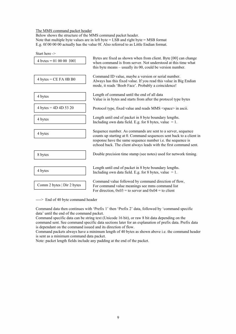
The MMS command packet header Below shows the structure of the MMS command packet header. Note that multiple byte values are in left byte = LSB and right byte = MSB format E.g. 0f 00 00 00 actually has the value 0f. Also referred to as Little Endian format. Start here ->
Bytes are fixed as shown when from client. Byte [00] can change when command is from server. Not understood at this time what ]
4 bytes = 01 00 00 [00 this byte means – usually its 00, could be version number.Command ID value, maybe a version or serial number. 4 bytes = CE FA 0B B0 Always has this fixed value. If you read this value in Big Endian
mode, it reads ‘Boob Face’. Probably a coincidence! Length of command until the end of all data
Value is in bytes and starts from after the protocol type bytes
4 bytes
Protocol type, fixed value and reads MMS <space> in ascii. 4 bytes = 4D 4D 53 20
Length until end of packet in 8 byte boundary lengths. Including own data field. E.g. for 8 bytes, value = 1.
4 bytes
Sequence number. As commands are sent to a server, sequence counts up starting at 0. Command sequences sent back to a client in response have the same sequence number i.e. the sequence is echoed back. The client always leads with the first command sent.
4 bytes
Double precision time stamp (see notes) used for network timing. 8 bytes
Length until end of packet in 8 byte boundary lengths. Including own data field. E.g. for 8 bytes, value = 1. 4 bytes
Command value followed by command direction of flow, For command value meanings see mms command list For direction, 0x03 = to server and 0x04 = to client Comm 2 bytes | Dir 2 bytes
----> End of 40 byte command header Command data then continues with ‘Prefix 1’ then ‘Prefix 2’ data, followed by ‘command specific data’ until the end of the command packet. Command specific data can be string text (Unicode 16 bit), or raw 8 bit data depending on the command sent. See command specific data sections later for an explanation of prefix data. Prefix data is dependant on the command issued and its direction of flow. Command packets always have a minimum length of 40 bytes as shown above i.e. the command header is sent as a minimum command data packet. Note: packet length fields include any padding at the end of the packet.
9
Known MMS commands This is a list of all the commands found to date. Commands are represented by a single hex byte value as shown below. The actual command byte is located within the MMS command packet header detailed earlier in this document. Command packets have data within them that is specific to the command itself. This means that a command packets’ length will vary, different procedures need to be applied depending on the command in use and the direction of the command (server to client or vice-versa) also determine the command data properties. This complicates matters a little, however, below is a breakdown of what is known so far. All commands are padded with zeros before sending over the network. The padding length ensures that the total command length (including all data) fits into an 8 byte length boundary. All text strings, unless otherwise stated, are sent as a 16 bit Unicode string type format. 01 To Server Prefix 1 f0 f0 f0 f0 - flags (see flags section) Prefix 2 0b 00 04 00 Then 1c 00 03 00 Then the structure as below Send the initial connect info including player version no. Client GUID (random) and the host address being connected to. This command is sent at the very start of protocol initiation. It sends local information to the server. The Unicode data string is made from the following data: “NSPlayer/7.0.0.1956; {128 bit local client GUID in hex text }; Host: The.Host.Net” + a null 0x00 + sometimes with a hidden data field showing more zeros (this seems optional). Notes: Client GUID is random, read the section ‘locally generated GUIDs’. The ‘Host’ field is optional – only used by versions of media player 7.0 or later (see below). The player version name must start with the value “NSPlayer”, if any other name of player is sent, the server will automatically send a default movie called ‘Upgrade Your Player’, regardless of any filename you may request. This is a 15 second movie telling you how to upgrade. The values after NSPlayer, can be anything, e.g. a version number like /7.0.0.1956 Only versions of media player 7.0 or later support a ‘MMS Proxy Server’ option. The ‘Host’ field indicates the actual streaming server domain or IP address, regardless of whether a proxy is being used or not. A proxy server can use this host address to then connect to the desired streaming server. This is why the ‘host’ field does not appear in older versions of media player – proxy servers are not supported below 7.0.
10
01 To Client Prefix 1 00 00 00 00 - ErrorCode Prefix 2 f0 f0 f0 f0 - flags (see flags section) Followed by structure as defined below. Server replies with own data including the server software version number and more. 0b 00 04 00 ?? 1c 00 03 00 ?? 00 00 00 00 00 00 f0 3f double precision value = 1 and unknown 01 00 00 00 ?? 01 00 00 00 ?? 00 80 00 00 ?? = unknown 00 00 a0 00 ?? or sometimes value shows 80 96 98 00 = 10000000 Ww ww ww ww Length of server version Xx xx xx xx Length of tool version Yy yy yy yy Length of download update player URL Zz zz zz zz Length of password encryption type Unicode strings follow of lengths given in the structure. If no field is required, the length = 0. Each length count represents a 2 byte field length for each Unicode character. It is interesting that server versions lower than 3.0 do not accept command 0x32 to server data dumps (see later in text). Media Player does not send them when less than v3.0. Presumably, this feature was not written in until that version. The Unicode strings are made from the following data: Server version + null like; 4.1.0.3858 or the latest currently shows 9.00.00.3101 Tool version + null like; 5.1.0.0 Update player URL + null like; http://www.theupdatesite.com/updateplayer.html Encryption type + null like; BASIC, DIGEST or NTLM Ending with 12 bytes of unknown data, sometimes as zeros, other times as hex data. Not all strings are present in a 0x01 command packet, but the server version seems to always be there. For a password protected session, BASIC or another encoding type string must be present. 02 To Server Prefix 1 f1 f0 f0 f0 - flags (see flags section) Prefix 2 ff ff ff ff Then 00 00 00 00 Then 00 00 a0 00 - unknown Then 02 00 00 00 - reflects the Header PacketIDType This sends the transport protocol, client IP address and client socket port to the server. The Unicode string is sent as below: “ \\123.456.789.012\TCP\1234” + null + optional Unicode data e.g. “0”. Optional data : This can show 10 bytes of unknown data when the transport protocol is UDP. Where: 123.456.789.012 is the client IP address, TCP (or UDP) states the transport protocol we want, And 1234 is the client TCP or UDP socket number
11
02 To Client Prefix 1 00 00 00 00 - ErrorCode Prefix 2 f1 f0 f0 f0 - flags (see flags section) Then nn nn nn nn - 4 bytes showing a length of data value as the
amount of 4 byte fields in its data. Note: this may not always be true! This value includes the length field itself. So, 4 bytes = 1.
Then Unicode string data follows. Response from protocol selection command 02. The text “Funnel Of The” or sometimes ‘Funnel of the gods’ is of unknown use normally seen in this data. Assume the transport protocol selection was accepted. 03 To Client Prefix 1 00 00 00 00 - ErrorCode Prefix 2 00 00 00 00 This indicates a protocol selection error from the server. It also indicates a close socket connection request from the server to the client. Connection is terminated after this command. 05 To Server Prefix 1 01 00 00 00 - CommandLevel Prefix 2 ff ff ff ff Then 8 zeros (unknown) could be double precision value Then Unicode string data as below. This command sends file path (at server) and file name request to the server. It does not include any IP or DNS information, just the path and name for the media. The Unicode data string consists of the following: “this/is/the/file/path/on/server/with/filename.ext” + null + unknown optional data like “2C3” Note: After a filename e.g. …/filename.asf there may also follow Digital Rights Management licence data. This is passed to the server as a parameter data string like this:- …/filename.asf?parameter1, parameter2 Just like any other .ASP or .JSP active input parameter string. Where parameter1 can = 0 and parameter2 shows 32 bytes of hex represented string data. If the media file requires this DRM data, and you do not supply the exact licence string, you get an error and you will be denied access. In that case, command 03 to client reports disconnection along with the ‘licence required’ errorcode. 05 To Client Prefix 1 00 00 00 00 - ErrorCode Prefix 2 04 00 00 00 - reflects the Media PacketIDType value Then struct follows Sending media file now. Includes the file play time. 01 00 00 00 Unknown but can change either 0 or 1. 00 00 00 00 Could be an offset time eg. 00 00 00 40 = 2 sec. 00 00 00 00 ?? 00 00 00 00 ?? 00 00 00 00 ?? Xx xx xx xx Shows file time less the buffer time as a single
precision float value. This value may only be valid during a seek operation. Otherwise it can show just 1.
12
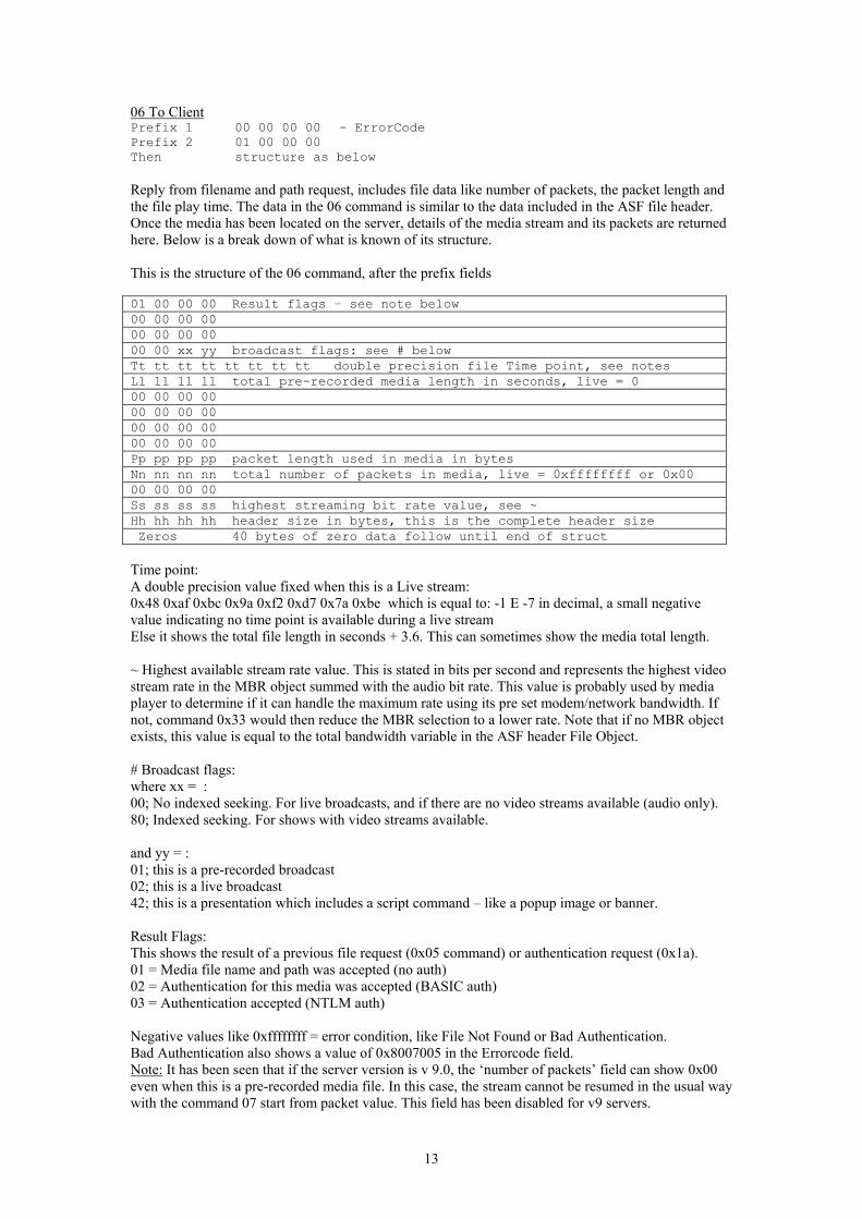
06 To Client Prefix 1 00 00 00 00 - ErrorCode Prefix 2 01 00 00 00 Then structure as below Reply from filename and path request, includes file data like number of packets, the packet length and the file play time. The data in the 06 command is similar to the data included in the ASF file header. Once the media has been located on the server, details of the media stream and its packets are returned here. Below is a break down of what is known of its structure. This is the structure of the 06 command, after the prefix fields 01 00 00 00 Result flags – see note below 00 00 00 00 00 00 00 00 00 00 xx yy broadcast flags: see # below Tt tt tt tt tt tt tt tt double precision file Time point, see notes Ll ll ll ll total pre-recorded media length in seconds, live = 0 00 00 00 00 00 00 00 00 00 00 00 00 00 00 00 00 Pp pp pp pp packet length used in media in bytes Nn nn nn nn total number of packets in media, live = 0xffffffff or 0x00 00 00 00 00 Ss ss ss ss highest streaming bit rate value, see ~ Hh hh hh hh header size in bytes, this is the complete header size Zeros 40 bytes of zero data follow until end of struct Time point: A double precision value fixed when this is a Live stream: 0x48 0xaf 0xbc 0x9a 0xf2 0xd7 0x7a 0xbe which is equal to: -1 E -7 in decimal, a small negative value indicating no time point is available during a live stream Else it shows the total file length in seconds + 3.6. This can sometimes show the media total length. ~ Highest available stream rate value. This is stated in bits per second and represents the highest video stream rate in the MBR object summed with the audio bit rate. This value is probably used by media player to determine if it can handle the maximum rate using its pre set modem/network bandwidth. If not, command 0x33 would then reduce the MBR selection to a lower rate. Note that if no MBR object exists, this value is equal to the total bandwidth variable in the ASF header File Object. # Broadcast flags: where xx = : 00; No indexed seeking. For live broadcasts, and if there are no video streams available (audio only). 80; Indexed seeking. For shows with video streams available. and yy = : 01; this is a pre-recorded broadcast 02; this is a live broadcast 42; this is a presentation which includes a script command – like a popup image or banner. Result Flags: This shows the result of a previous file request (0x05 command) or authentication request (0x1a). 01 = Media file name and path was accepted (no auth) 02 = Authentication for this media was accepted (BASIC auth) 03 = Authentication accepted (NTLM auth) Negative values like 0xffffffff = error condition, like File Not Found or Bad Authentication. Bad Authentication also shows a value of 0x8007005 in the Errorcode field. Note: It has been seen that if the server version is v 9.0, the ‘number of packets’ field can show 0x00 even when this is a pre-recorded media file. In this case, the stream cannot be resumed in the usual way with the command 07 start from packet value. This field has been disabled for v9 servers.
13
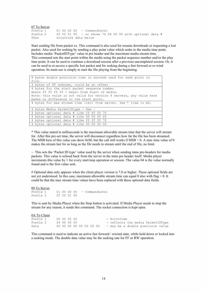
07 To Server Prefix 1 01 00 00 00 - CommandLevel Prefix 2 ff ff 01 00 - or shows 76 04 00 00 with optional data # Then structure data below Start sending file from packet xx. This command is also used for resume downloads or requesting a lost packet. Also used for seeking by sending a play point value which seeks to the media time point. Includes media ‘PacketIDType’ value in pre header and the maximum media stream time. This command sets the start point within the media using the packet sequence number and/or the play time point. It can be used to continue a download session after a previous uncompleted session. Or, it can be used to re-access a specific lost packet and for seeking during a fast forward or re-wind operation. Its main use is simply to start the file playing from the beginning. 8 bytes double precision time in seconds used for seek point in file. 4 bytes of FF unknown, could be an offset 4 bytes for the start packet sequence number where ff ff ff ff = begin from start of media. Note: this value is not valid for version 9 servers, any value here makes no difference to the start point. 4 bytes for max stream time limit from server. See * time in mS.
4 bytes Media PacketIDtype - See ~ 4 bytes optional data # like ff ff ff 7f 4 bytes optional data # like 00 00 00 00 4 bytes optional data # like ff ff ff 7f 4 bytes optional data # like 00 00 00 00 * This value stated in milliseconds is the maximum allowable stream time that the server will stream for. After this pre-set time, the server will disconnect regardless how far the file has been streamed. The MSB byte of this value can show 0x80, but the call still works if MSB = 0. A max time value of 0 makes the stream last for as long as the file needs to stream until the end of file, no limit. ~ This sets the ‘Packet ID type’ value used by the server when sending mms pre-headers for media packets. This value is echoed back from the server in the mms pre header itself. Media player increments this value by 1 for every start/stop operation or session. The value 04 is the value normally found and is the first value sent. # Optional data only appears when the client player version is 7.0 or higher. These optional fields are not yet understood. In this case, maximum allowable stream time can equal 0 also with flag = 0. It could be that the max stream time values have been replaced with these optional data fields. 09 To Server Prefix 1 01 00 00 00 - CommandLevel Prefix 2 ff ff 01 00 This is sent by Media Player when the Stop button is activated. If Media Player needs to stop the stream for any reason, it sends this command. The socket connection is kept open. 0A To Client Prefix 1 00 00 00 00 - ErrorCode Prefix 2 04 00 00 00 - reflects the media PacketIDType Data 00 00 00 00 00 00 00 00 - may be a double precision value This command is used to indicate an active fast forward / rewind state, while held down or locked into a seeking mode. The double data value may be the seeking rate for FF or RW operation.
14
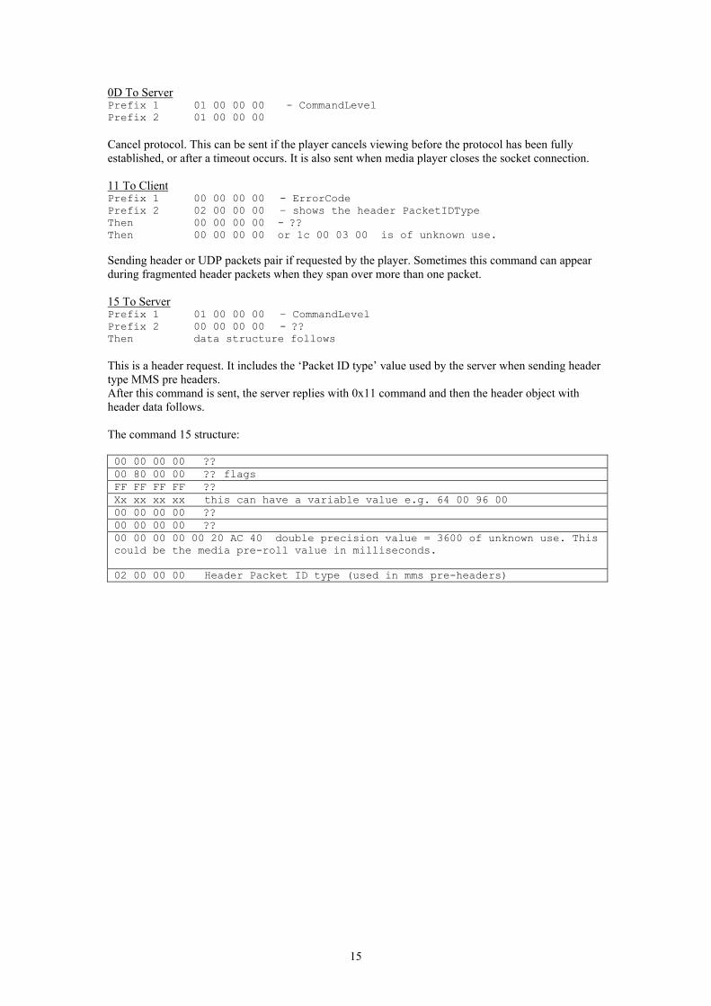
0D To Server Prefix 1 01 00 00 00 - CommandLevel Prefix 2 01 00 00 00 Cancel protocol. This can be sent if the player cancels viewing before the protocol has been fully established, or after a timeout occurs. It is also sent when media player closes the socket connection. 11 To Client Prefix 1 00 00 00 00 - ErrorCode Prefix 2 02 00 00 00 – shows the header PacketIDType Then 00 00 00 00 - ?? Then 00 00 00 00 or 1c 00 03 00 is of unknown use. Sending header or UDP packets pair if requested by the player. Sometimes this command can appear during fragmented header packets when they span over more than one packet. 15 To Server Prefix 1 01 00 00 00 – CommandLevel Prefix 2 00 00 00 00 - ?? Then data structure follows This is a header request. It includes the ‘Packet ID type’ value used by the server when sending header type MMS pre headers. After this command is sent, the server replies with 0x11 command and then the header object with header data follows. The command 15 structure: 00 00 00 00 ?? 00 80 00 00 ?? flags FF FF FF FF ?? Xx xx xx xx this can have a variable value e.g. 64 00 96 00 00 00 00 00 ?? 00 00 00 00 ?? 00 00 00 00 00 20 AC 40 double precision value = 3600 of unknown use. This could be the media pre-roll value in milliseconds. 02 00 00 00 Header Packet ID type (used in mms pre-headers)
15
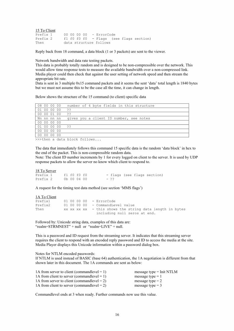
15 To Client Prefix 1 00 00 00 00 - ErrorCode Prefix 2 f1 f0 f0 f0 - Flags (see flags section) Then data structure follows Reply back from 18 command, a data block (1 or 3 packets) are sent to the viewer. Network bandwidth and data rate testing packets. This data is probably totally random and is designed to be non-compressible over the network. This would allow time response tests to measure the available bandwidth over a non-compressed link. Media player could then check that against the user setting of network speed and then stream the appropriate bit rate. Data is sent in 3 multiple 0x15 command packets and it seems the sent ‘data’ total length is 1840 bytes but we must not assume this to be the case all the time, it can change in length. Below shows the structure of the 15 command (to client) specific data 08 00 00 00 number of 4 byte fields in this structure 01 00 00 00 ?? 00 00 01 00 ?? Nn nn nn nn gives you a client ID number, see notes 00 00 00 00 01 00 00 00 ?? 00 00 00 00 00 00 00 00
>>>then a data block follows... The data that immediately follows this command 15 specific data is the random ‘data block’ in hex to the end of the packet. This is non-compressible random data. Note: The client ID number increments by 1 for every logged on client to the server. It is used by UDP response packets to allow the server no know which client to respond to. 18 To Server Prefix 1 f1 f0 f0 f0 - flags (see flags section) Prefix 2 0b 00 04 00 - ?? A request for the timing test data method (see section ‘MMS flags’) 1A To Client Prefix1 01 00 00 00 - ErrorCode Prefix2 01 00 00 00 - CommandLevel value Then xx xx xx xx - this shows the string data length in bytes
including null zeros at end. Followed by: Unicode string data, examples of this data are: “realm=STRMNEST” + null or “realm=LIVE” + null. This is a password and ID request from the streaming server. It indicates that this streaming server requires the client to respond with an encoded reply password and ID to access the media at the site. Media Player displays this Unicode information within a password dialog box. Notes for NTLM encoded passwords: If NTLM is used instead of BASIC (base 64) authentication, the 1A negotiation is different from that shown later in this document. The 1A commands are sent as below: 1A from server to client (commandlevel = 1) message type = Init NTLM 1A from client to server (commandlevel = 1) message type = 1 1A from server to client (commandlevel = 2) message type = 2 1A from client to server (commandlevel = 2) message type = 3 Commandlevel ends at 3 when ready. Further commands now use this value.
16
1A To Server Prefix1 01 00 00 00 - CommandLevel Prefix2 01 00 00 00 - flags unknown Data xx xx xx xx -shows the length in bytes of the
encrypted password data Then data follows The data that follows is an encrypted password and ID key, which is then sent to the server to gain access to its content. Passwords are ‘content’ specific rather than ‘Server’ specific. This means if your password is disclosed to someone, they will only have access to that individual media file, not the entire server site. This rule may change depending on the servers’ policy. This is a reply to the server sent 1A command. The encoded format string is simply: where ID is your id and PASSWORD is your password! ID:PASSWORD (including the colon : in the middle) Password encryption methods in use in MMS (server 2000 and later): BASIC -Uses BASIC authentication format with a Base64 encoding method NTLM - Now widely used by version 9 MMS servers. (NT/LanManager) On failure, the next command sent is the 0x06 to client showing an error code (prefix 1 = 0x80070005). This shows that password access was denied. On success, CommandLevel value increments by 1. 1B To Client Prefix 1 00 00 00 00 - ErrorCode Prefix 2 04 00 00 00 - reflects the media PacketIDType value This is a network timer test. The server sends these to the client at regular intervals, about 1 every minute. The client must reply within a certain time limit otherwise be cut off. 1B To Server Prefix 1 01 00 00 00 - CommandLevel Prefix 2 ff ff 01 00 This is a response to the 1B request, referred to as ACK. A 1B reply indicates all is ok and no packets are missing. This command is used for acknowledging a network test sent from the server at regular intervals. These tests make sure that the viewer is still receiving the media by making the viewer return a 1B command every minute or so on demand form the server. If there was a problem at the client end with a lost packet or bad connection, the 07 command is used to re-sync. No data field is required, although extra data does show here sometimes. 1E To Client Prefix 1 00 00 00 00 - ErrorCode Prefix 2 04 00 00 00 - reflects the media PacketIDType value End of media stream – stop playing. This also tells the player to empty what is left it its buffer to the end.
17
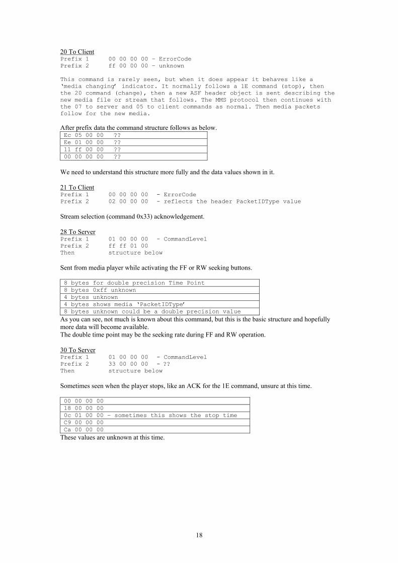
20 To Client Prefix 1 00 00 00 00 – ErrorCode Prefix 2 ff 00 00 00 – unknown This command is rarely seen, but when it does appear it behaves like a ‘media changing’ indicator. It normally follows a 1E command (stop), then the 20 command (change), then a new ASF header object is sent describing the new media file or stream that follows. The MMS protocol then continues with the 07 to server and 05 to client commands as normal. Then media packets follow for the new media. After prefix data the command structure follows as below. Ec 05 00 00 ?? Ee 01 00 00 ?? 11 ff 00 00 ?? 00 00 00 00 ??
We need to understand this structure more fully and the data values shown in it. 21 To Client Prefix 1 00 00 00 00 - ErrorCode Prefix 2 02 00 00 00 - reflects the header PacketIDType value Stream selection (command 0x33) acknowledgement. 28 To Server Prefix 1 01 00 00 00 - CommandLevel Prefix 2 ff ff 01 00 Then structure below Sent from media player while activating the FF or RW seeking buttons. 8 bytes for double precision Time Point 8 bytes 0xff unknown 4 bytes unknown 4 bytes shows media ‘PacketIDType’ 8 bytes unknown could be a double precision value
As you can see, not much is known about this command, but this is the basic structure and hopefully more data will become available. The double time point may be the seeking rate during FF and RW operation. 30 To Server Prefix 1 01 00 00 00 - CommandLevel Prefix 2 33 00 00 00 - ?? Then structure below Sometimes seen when the player stops, like an ACK for the 1E command, unsure at this time. 00 00 00 00 18 00 00 00 0c 01 00 00 – sometimes this shows the stop time C9 00 00 00 Ca 00 00 00
These values are unknown at this time.
18
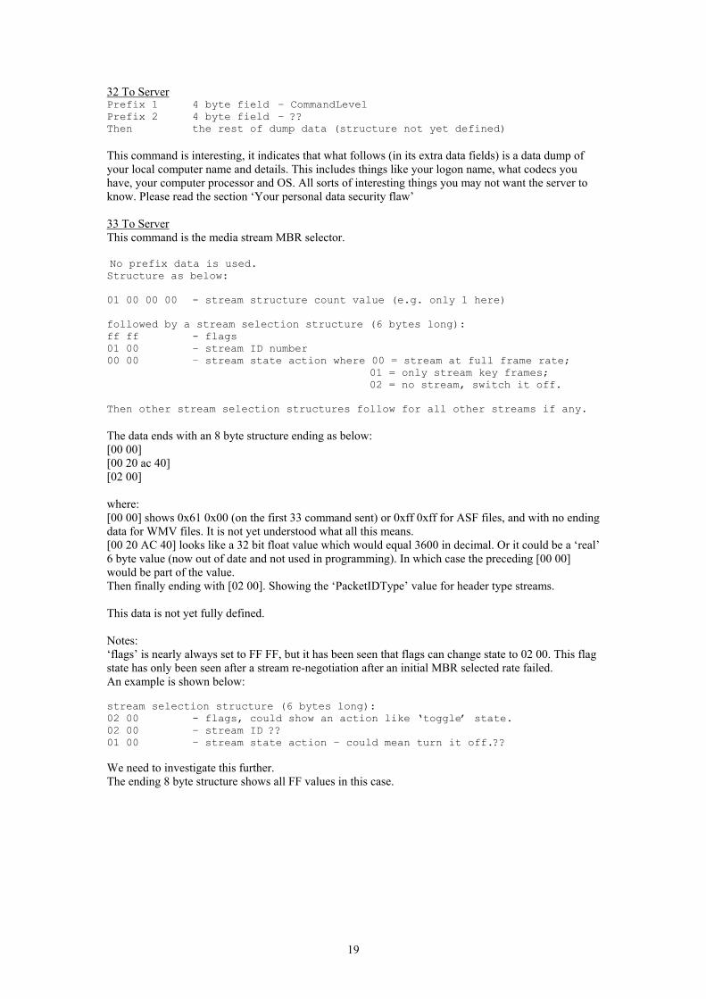
32 To Server Prefix 1 4 byte field – CommandLevel Prefix 2 4 byte field – ?? Then the rest of dump data (structure not yet defined) This command is interesting, it indicates that what follows (in its extra data fields) is a data dump of your local computer name and details. This includes things like your logon name, what codecs you have, your computer processor and OS. All sorts of interesting things you may not want the server to know. Please read the section ‘Your personal data security flaw’ 33 To Server This command is the media stream MBR selector. No prefix data is used. Structure as below: 01 00 00 00 - stream structure count value (e.g. only 1 here) followed by a stream selection structure (6 bytes long): ff ff - flags 01 00 – stream ID number 00 00 – stream state action where 00 = stream at full frame rate;
01 = only stream key frames; 02 = no stream, switch it off.
Then other stream selection structures follow for all other streams if any. The data ends with an 8 byte structure ending as below: [00 00] [00 20 ac 40] [02 00] where: [00 00] shows 0x61 0x00 (on the first 33 command sent) or 0xff 0xff for ASF files, and with no ending data for WMV files. It is not yet understood what all this means. [00 20 AC 40] looks like a 32 bit float value which would equal 3600 in decimal. Or it could be a ‘real’ 6 byte value (now out of date and not used in programming). In which case the preceding [00 00] would be part of the value. Then finally ending with [02 00]. Showing the ‘PacketIDType’ value for header type streams. This data is not yet fully defined. Notes: ‘flags’ is nearly always set to FF FF, but it has been seen that flags can change state to 02 00. This flag state has only been seen after a stream re-negotiation after an initial MBR selected rate failed. An example is shown below: stream selection structure (6 bytes long): 02 00 - flags, could show an action like ‘toggle’ state. 02 00 – stream ID ?? 01 00 – stream state action – could mean turn it off.?? We need to investigate this further. The ending 8 byte structure shows all FF values in this case.
19
MMS Flags (prefix data for some commands) Flag fields are found in prefix data fields in some (not all) MMS commands. This is an attempt to describe how they work and how the client and server can modify the value of these flags as the protocol progresses during initialisation. The exact purpose of these flags has been difficult to examine because their state rarely change or show meaningful data. But over time and experimentation, a pattern is starting to emerge. We will now show what is known about these flags fields. Generally, flags are ‘echoed’ by the server to the client player and can be modified if the state must be changed for any reason. Therefore, by the end of the exchange from client to server and back again, we are left with a valid flags state that both client and server have agreed to. It seems the main purpose of these flags is to determine the current player and server version types and network timing methods to use for both those versions. Either UDP packet pair or TCP 0x15 command packets can be selected by the flags state. Read the MMS commands and UDP packet pair sections for further information on these methods. < MMS protocol flags start here > Command 0x01 to server -> start flags something like 0xf0f0f0f0. If this value starts with 0x00000000, then no modifications are carried out as below – all flags remain zero for all states all the way to the end. This is true for very old media player versions less than 6.4. (like the original windows 95/98 install version). Command 0x01 to client -> Server echo of previous command 01 flags. However, flags can be incremented by 1 if the server does not support any timing packet methods. This is true with old server versions less than 4.0. As an example: if flags were 0xf0f0f0f0 from the client, the server could change the value to 0xf1f0f0f0 (little endian) if both UDP and TCP timing methods are not supported, else no modification is needed - echo 0xf0f0f0f0. Command 0x18 to server -> Client flags indicate what timing tests to do, if any. Flags start as 0xf0f0f0f0 and can be modified as follows : increments by 0x01 if the TCP timing method is required, increments by 0x811 if the UDP packet pair method is required, decrements by 0x01 if no timing method is required by the client. This is true when the player has its ‘Auto Detect’ internet speed tick unchecked. This is because it then uses a pre-defined connection speed and does not require timing packet tests. Flags = 0 if the player version is very old, less than 6.4, in this case no timing tests are done. Command 0x15 to client -> Server echo of flags from the previous 18 command. No modifications are needed. However, if the TCP method has been requested as the timing test, we send 3 packets of this 0x15 command (with random test data). If any other test method is required, or maybe non at all, then only one 0x15 command is sent with no random test data block. Command 02 to server -> Client echo of flags from previous 15 command No modifications are needed. Command 02 to client -> Server echo of flags from previous 02 command. No modifications are needed. <end of flag modifications – we are left with a completed flags state. We can now determine what timing method (if any) to use for this session > It seems very likely that any of these commands could alter the state of flags depending on the command’s purpose. But we have only seen the changes outlined above. This seems to be a reasonable basis for understanding the operation of flags during the modification of the flags state.
20
About Error Codes and Command level values – Prefix 1 data I expect this section to be updated as error handling becomes more detailed. Error handling is very important. Up until now, not much was known about mms errors. It seems all MMS commands have error code return fields to help control protocol flow. We must understand more about these errors so that the protocol can become more robust under fault conditions. Prefix 1 data (ErrorCode) when command is server to client. When a command fails for whatever reason, this field shows an Error Code. Where 00 = ok. Some example codes are shown below but there are many more unknown codes. Values are shown here in normal hex, these are converted to little endian format for prefix 1 data. 0xC00D001A file was not found 0XC00D000E the network is busy 0xC00D000F too many connected sessions to server exist, cannot connect 0xC00D0029 the network has failed – connection was lost 0xC00D0034 There is no more data in the stream (UDP) 0x80070005 You do not have access to the location or file 0xC00D0013 There was no timely response from the server 0x80070057 A parameter in the location is incorrect 0x8000FFFF file failed to open WinSock error codes from servers Error codes between 0x80072711 and 0x80072AFC are WinSock API errors, where the actual API error value is the error code masked with 0xFFFF. E.g. 0x80072711 and with mask 0xFFFF = 0x2711 = API error decimal 10001 for WinSock It is known that something in the order of 100 or more error values exist. A module written purely to handle error codes and messages should be used to handle errors as they are detected. Prefix 1 data (CommandLevel) when command is Client to Server This value normally shows: 0x01 (little endian 01 00 00 00) and shows what we have decided to call a CommandLevel value. This value has only been seen to change after a 1A password negotiation has taken place. After both 1A server side and 1A client side commands have been correctly sent, this value increments by 1 to the next protocol ‘Level’. It may indicate the security level, or it may simply be a program state change indicating the core mms function was left, then re-entered. After both 1A password commands have finished, this value must increment for correct protocol operation. This value can also increment after a password retry failure. In that case, prefix 2 (PacketIDType) increments by 1 also.
21
MMS Command Protocol State Sequences There is a common sequence to commands sent and returned. Although it is interesting that you can change some command sequences and it still works, its probably best left alone. Below shows a typical streaming session in order of sequence. Starting at top left of table. Client Sent Command -> NETWORK <- Server Sent Command 01 - start with player version, - 01 - server software version, tool etc GUID and optional host name 18 – packet timing data request - 15 – timing test replies
(1 or 3 of) see notes 02 – transport protocol select - 02 – protocol accepted UDP/TCP 03 – protocol failed 05 - media file name/path request - 1A – request for client password. (only if password required by
server, else send 06 command and ignore all 1A commands)
1A – send user password (encrypted) - 06 - media file details / packet info 15 - request media header - 11 – header request was accepted.
< If the client player flags requested UDP packet pair timing data, it is sent here > < At this point, the server sends the whole header object data > 33 - send stream ID switch selection - 21 – streams were accepted 07 - start streaming from packet xx - 05 - media packets follow < ### The server then sends media packets with mms pre-headers ### > During a stream, the server sends a 1B command about 1 every minute. The client replies with 1B also to keep the connection alive. A stream is stopped by the server - by sending a 1E command to client A stream is stopped by the client - by sending a 09 command or 0D command to server Extra notes: The server terminates streaming at EOF or end of live broadcast with the command 1E This allows the media player buffer to empty gracefully first before ending. Command 09 to server keeps the TCP connection open but halts the media player and server. Command 0D actually closes the TCP socket connection. The 09 to server stop command is usually followed by a 32 to server command with its dump data structure. Command 32 is only sent if the server version accepts command 32 data dumps. See notes. If the initial mms protocol fails before fully establishing the link (maybe the server or player times out) then the 0D command is used to close the connection. Media player times out after around 15 seconds if the MMS protocol fails. Also, if the user closes the player during mms initialisation, the 0D is sent to the server to indicate connection closure. The server can use a 20 command to change the current media stream without re-starting the player. After a 20 command to client is sent, a new header object is also sent and a new media stream then follows after the usual 07 to server and 05 to client mms commands. Note, it seems that 33 to server and 21 to client commands are not required, but are seen in some streams. For NTLM encoded password streams please note that the 1A command protocol is different as from that shown above. Please see the command 1A to client section in this document.
22
MMS Pre Headers Media and header packets are prefixed with mini headers attached at their start. I will refer to these as MMS pre-headers. This is an 8 byte long header attached to the start of every streamed media / header packet. This application protocol level header is used for carrying important packet information like the packet sequence number, PacketIDType, UDP count / TCP flags and packet length. MMS Media and Header Object Packet Pre headers 4 bytes Sequence number
1 byte PacketIDtype
1 byte UDP sequence / TCP flags
2 bytes Packet length
Sequence Number – 4 bytes Increments as packets are received. This is an absolute packet number and its starting value shows from the point at which the stream is started. I.e. start = 0 for pre-recorded media and start = another value for the live stream point where you came in. Packet ID type – 1 byte This increments for every stop/play action by media player. Every time a new play session is started, this counts by one. It can be thought of as the packet type ID or client session number for that session. After an initial start value as shown below, it then counts up to 0xff and scrolls around to 0x00 and so on. The server effectively echo’s this value back to the player using the last ID value sent to it. This value can be preset by : Client to server command 0x07 (for media type packets) Client to server command 0x15 (for header type packets). See command specific data for those commands for more details. We can pre-set these values when we send commands to a server rather than increment them. This gives us a handle on header and media packet types if we wish. Normal Packet ID initial assignments: 0x04 = start value for media packets 0x02 = start value for header packets 0xff = used for command 20 continue with new header data UDP sequence / TCP Flag - 1 byte (For UDP streaming only) This sequence is a relative packet number and always starts from 0 regardless where you came in to the stream. It increments by 1 for every UDP packet sent to the client. This sequence is used for UDP sequence checking and error correction. After the count limit of 0xff, the value wraps around to 0x00, and so on. (unsigned char). UDP sequence / TCP Flag – 1 byte (For TCP streaming only) This flag has preset values of : 0x00 shows the middle of packet series 0x04 shows the first packet of a packet series 0x08 shows the last packet of a packet series 0x0C shows there is only 1 packet in this series 0x10 shows a UDP packet pair timing packet (see MMS UDP Timing Packet Pairs info) Packet Length - 2 bytes little endian The total length in bytes of the packet, up to and including the last packet byte. It includes the pre-header field length itself
23

MMS UDP Timing Packet Pair Pre Headers 1 byte Sequence number
3 bytes flags = f0 f0 f0
1 byte ID = 0xff
1 byte flag = 0x10
2 bytes Packet Length
Where: Sequence number starts at 00 and wraps around after 0xff. 3 bytes shown as ‘flags’ is always f0 f0 f0. ID is always 0xff and is the Packet ID Type for ‘UDP packet pairs’ 1 byte shown as ‘flag’ is fixed as 0x10 and is the UDP sequence / TCP flags value for packet pairs. Packet Length includes the pre header field length as part of its value Packet pairs are used in UDP transport protocol timing tests. Two random data packets are send to the client player so it can time the interval between them and determine available bandwidth over the network while using UDP.
24
ASF UDP/TCP Packet resynchronisation Ok, what can be done if we get a corrupt packet? Or maybe it doesn’t arrive at all? IP packets (and thus the ASF packets within) can be tested either by checksum testing (requires access to the IP packet checksum in header), or maybe just by testing the ASF packet for a valid sequence number. Unfortunately, UDP has no way of recovering a lost or corrupt packet because UDP is connectionless and therefore has no handshake to re-request the packet. Bad or lost UDP packets are simply deleted if its checksum is incorrect, resulting in a missing packet – and a missing count sequence. UDP checksum testing is done within the Winsock32 layer (for windows) of which we have very little control. TCP on the other hand does recover lost and corrupt packets quite effectively using its checksum and re-send protocol. For this reason, TCP is far more robust when it comes to downloading and even real time viewing is improved. TCP packets very rarely get lost. UDP packets can and usually do get lost in the system, especially under heavily congested network conditions. For TCP packet viewing / recording, there is not much to do other than receive the data as it arrives and then deal with it accordingly. TCP takes care of all the headaches of errors, lost packets and anything else that comes along 99.9% of the time. For UDP packets, the application must take care of what happens next. If a packet gets lost of out of sequence, the player can do either of the following:- 1) Request the missing packet again from the server by using a UDP re-request command (see
below). When this happens, the lost packet (we detected a missing UDP sequence count) gets re-sent to the viewer. Hopefully this re-sent packet arrives in time and is placed in the buffer before its actually viewed. This being the case, the viewer is unaware of any loss and the media plays normally. If the re-sent packet arrives too late, noting can be done and a missing frame or two will cause the media player to freeze momentarily.
2) We can ignore the bad packet (maybe just ignore that we lost a sequence count) and keep playing, the player would resume on the next good packet anyway.
The best course of action regarding lost packets is still under investigation. A re-send is of course necessary for a download, we do not want to miss any packets if writing a file. But for a viewing session, it’s probably not needed. MMS application protocol does handle lost or corrupt packets even when using UDP, but it handles them within media player, using the MMS 07 command for TCP seeking and the so called ‘beef food’ command for UDP re-sends. Below shows what is known about the UDP re-send command – I’ve named it the ‘beef food’ command. This command is very different to the normal TCP MMS commands we have talked about already. This command is sent across a UDP datagram to the server and has its own defined command make up. This command is sent to the server on port 1755, just like a TCP command. [4 bytes] Header ID. This value is fixed as 0x0d, 0xf0, 0xef, 0xbe. Strangely, this value reads ‘beef food’ in big endian hex mode! Just like the ‘boob face’ fixed bytes in an MMS command. This must be a joke:0) [4 bytes] Client ID (found in 0x15 command from server) [2 bytes] Always 0x01, 0x00 fixed value – could be UDP command 01. [2 bytes] Shows how many packets are to be re-sent to the client (count of fields below) [Variable length] 4 byte fields. This is a list of packets to be re-sent. Note the value of each field can only range from 0 – 255 (even though it’s a 4 byte field), after that its wraps around to zero again.
It is unknown whether other UDP commands exist, but for now, this one is very useful. If the requested re-send packet fails to respond from the server, media player gives up after 5 attempts.
25
Lets talk a little about the ASF format ASF or ‘Advanced Systems Format’ developed by Microsoft, is a media file format just like many others e.g. AVI, RM and MOV. ASF is not to be confused with MMS protocol, although you will see the two being used together in nearly all applications of Windows Media streaming. Background to ASF We need to know certain things about the ASF file format. This document will not go into great detail about ASF, information is already available on other web sites. What we can say here is that the format version we need is 1.0 and not 2.0. Version 2.0 being the version that Microsoft developed later and then decided not to use. The two versions are quite different in key areas. Microsoft has not released details* on v1.0 probably again like MMS protocol, trying to keep the whole thing under their control. Version 2.0 has been published, but is of no use because it has never been implemented (as far as I know of). *Latest News : - MicroSoft has now revealed its ASF 1.0 spec and is now posted on their website. Date: 3rd Feb 2002. Use that document alongside this one and you get the whole picture. Locally generated GUID numbers When communicating with a streaming server, it is required that you send a locally generated GUID (during command 01). A GUID is a specially generated unique random number which can only be generated from your computer. The system is used commonly with applications over the internet. This client GUID is of the same format as the GUID’s used in ASF headers i.e. 16 bytes long (128 bits). Although the application is some what different and should not be confused. Client GUID’s are used by streaming servers to keep track of clients address while streaming, data can be routed back to the exact connection. Log files can also be made at the server with data statistics become available. Your own GUID will always be different, every time you send a GUID, it is what it says – unique at that time. It will never be repeated by your computer or anyone else’s computer, well, not possibly until after the year 3100 when GUID values will start to wrap around again. MMS Proxy Servers MMS protocol can work through a proxy server as well as a direct connection to a streaming server. This may be required if you are operating within an intra-net or local area network. An example of this could be a business network with a shared server (or proxy server) for all the clients to access the outside world internet. Proxy servers usually have security restrictions in place like firewall and email checking measures. A client operating within an intra-net like this can only access the outside world (internet) via such a server. This means a client wanting to access a streaming server outside the network must access it via their proxy server. Assuming the IT administrator of the proxy server allows the ports required for streaming media (windows uses port 1755 for commands and usually 7000 for UDP streams) then this can be achieved by setting media player to connect to the proxy server rather than directly to the streaming server. The effect is that the proxy becomes transparent. A client is effectively connected to the streaming server without any concern of the proxy’s operation. Normally what happens during a direct connection is this: The media URL is first examined and the IP address (or domain name) is resolved from the address entered. Like : mms://this.server.net/myfile.asf would give ‘this.server.net’ as the domain name. Once this domain is resolved using a DNS resolver or similar function then you may end up with a direct IP address looking something like: 123.456.789.123. This is the actual TCP socket address that the MMS protocol will connect to. All commands using MMS communicate using this IP. But with a proxy server we do this: Ignore the media URL domain and allow the proxy option URL to override the IP address of the URL domain name. This allows the client to connect directly to the proxy IP, rather than the streaming server itself. You can also override the Port number for the connection too. So instead of TCP port 1755, any port number could be used. Remember that the proxy server ‘redirects’ its data to the actual streaming server over the internet. Therefore the port you use to connect to the proxy is only what the proxy needs and is not necessarily what the streaming server needs. Of course, redirection from your selected proxy port to the required 1755 streaming media port would have to be set by the IT administrator of the proxy. This cannot normally be set by the client for security reasons. Note 1: Although a proxy connection does not require the domain name or IP part of the media URL, this data is still used to formulate the client to server MMS command 0x01, and is referred to as ‘Host’ in that command. Note 2: Versions of media player less than 7.0 do not support MMS proxy servers. And the command 01 does not send the ‘Host’ data field for that reason. HTTP protocol proxies are support by all players.
26
Notes regarding packet lengths and data rates ASF media files have a fixed packet length (version 1.0). Even if the data length sent over a network is less than the packet length, padding zeros are placed in the file to ensure the packet length remains fixed. However, while a file is being streamed, the streaming server only sends the data and not the padding. Sending padding in a stream would drastically increase the overhead and reduce the effective data rate. For this reason, we must determine what the packet length is in order to reconstruct the file, then we can apply padding to the packets as we download them. We can then save it as the original ASF format with padding. One way to do this is by using the information in the ASF header once its received or another way is by reading the data held in the server to client command 06. We could use the client command 06 data if we were downloading a format other than ASF. Some of the data in the ASF header is effectively sent in this 06 command. We can roughly calculate the original media packet length by: Packet length in bytes = size of ASF file divided by the number of packets in the file. Or for a better way, data is available in the File header object (see the ASF header) giving max and min packet lengths. These will be equal for ASF version 1.0 This simple calculation above works, although it may not be accurate for very small files like say 10 seconds playing time or less. Below is a table of pre-recorded data rates and packet lengths. A value given by the calculation could be approximated to this table, although beware, other bit rates are also used. Modem/network rate Actual bit rate (if different) Approx. ASF Packet length 28.8k 22kbps 900 (seems to be the minimum size) 56k 37kbps 947 100k 1280 250k 3200 300k 3840 700k 8960 2000k 25600 You can download broadband media files with a narrow band modem! Remember that the bit rate is the pre-recorded (maximum) data rate for the stored media file, and not necessarily the rate of which it can be viewed on line. Live streaming bit rates can only be as fast as your internet link will allow, this is due to the nature of real time streaming. You can only empty a glass of milk so fast by sucking through a thin straw! However, while downloading, it is possible to download a broadband media file with a narrow modem stored on a streaming server (not live). This is because although your modem may be say only 56k, we send no protocol to say that the data received is not in sync with the server. A real time viewer like media player would send re-send commands to re-sync. So by not issuing ‘re-send’ packet commands, the media file is effectively ‘buffered’ at the server before sending (assuming TCP transport protocol is used, note – servers using UDP would send the stream regardless of modem speed and data would be lost). Attempting to view (with media player) a broadband file with a narrow band modem would fail because the viewer software would try to re-sync all of the time, issuing re-rend commands and thus causing the network to eventually fail. But our download program does not send these mms re-send commands, and this allows the stream to keep coming regardless of the actual streaming bit rate. Of course the file takes longer to download, sucking through a straw will eventually empty a glass, it just takes longer! We are now not in real time here, but you do get the file, and its broadband.
27
Time Codes, media packets and ASF headers for Live broadcasts Relative and Real Time We need to talk here about asf time codes. While a stream is being sent to a viewer, each media packet contains certain time codes stated in milliseconds. These time codes are embedded in each packet of the media and in turn, increment in time to the next time code. If the stream is a pre-recorded media held on a streaming server, the first received time code will always be zero. The time codes will then increment as the media progresses. This is referred to as Relative time, i.e. t = 0 at the start of the file and restarting the file again will reset its t value to 0. If the stream is a Live stream like a TV broadcast however, the first time code received could be any value, depending on where in the stream time we came in. This is referred to as Real time. I.e. t = 0 only at the start of the broadcast and not necessarily where we came in, it is time as it actually happens. To convert Real to Relative time, we use a simple offset as below: New relative time = the currently read media time - first packet’s media time. Media packet time conversion on the fly While downloading a pre-recorded file is a straight forward process of copying the media packet (and so its pre recorded time codes within) to local disk, for live situations its not so simple. In the case of a live broadcast, we must convert the packet’s Real time codes to Relative time before we can save the modified packet to file. We must do this because Windows media player software needs these times to be saved correctly. Otherwise the player gets confused, and even though we may only have say 10 minutes worth of recording to disk, the player may see it as a 1 hour file or whatever, depending on where we came in and not what we actually downloaded. Consequently, the file would not play even though we may have downloaded actual media data, their time related information would be incorrect. A conversion to Relative time is needed to correct this effect, and in our software, we do this on the fly while actually downloading. To explain exactly which bytes need to be addressed in the packet for time modification is a rather complicated process and requires knowledge of the actual ASF media packet format. We can follow the rules of the ASF format and from that locate the send time and object times within the packet. Typically, there may be something like 3 to 5 object segments in each ASF packet that need to have their time codes modified to relative time. To further understand the rules of ASF media and their time codes, I suggest reading the ASF 1.0 document available on the net. I will not go into that specification here. There is also a diagram showing approximate time code locations later in this document.
28
ASF header update when finished downloading Another important point is the ASF header itself must be re-written with new download size and total playing time data for live streams. Of course, this can only be done when the download has finished otherwise we would not know the length of the file or its playing time. In a live stream, the header is sent from the server at the point where the viewer came in. And because we could be anywhere in the stream and the length of the stream is unknown (its live) data in the asf header like Total File Time and Play Time Duration are not set. Values like 0x00000000 are sent in the header instead, total packets would be 0xffffffff or 0x00. Once we have finished downloading a broadcast, either by the user stopping a download or maybe the broadcast ends then we must use the data we have to re-write these now known values back into the header we already saved on disk. This means the asf file header (see file object and data objects in the ASF 1.0 document) is updated with new file play time and file total time values to allow the media player to understand the saved file and its time scales. The result is, on playing the downloaded file, t = 0 always at the start of the file and so the file plays from the start where we came in and for the correct length of time. Other values are also updated in the header like number of packets, total file size in bytes, the data chunk length in bytes and the FILE / LIVE flag is set to FILE. ASF File Finishing - Summary 1) While downloading a pre-recorded file, we do not need to make any modifications to either the media packets time code or the asf header. Packets are written straight to disk with header object. 2) While downloading Live broadcasts, we need to modify all time codes of media packets and times of the objects within them to relative time, i.e. t = 0 at start of file. We also need to update the asf header (only after a completed LIVE download) with new time related data like, total time of file, play time as well as other data like total file size, number of packets and the broadcast flags are set to allow seeking (Pre-recorded = true). Note: video seeking only works on Media Player v6. Not v7! To make local files seek enabled with player 7.0 or later, you must include an index seeking object at the very end of the ASF file. One index object for every stream in the media must be included. Read the ASF specification for more details about the index-seeking object. IEEE 754-1985 double precision values This is a 64 bit double precision value. In MMS, it is usually used as a very accurate time value and can be seen in many MMS commands. They also appear in MMS command headers and probably used for network timing detection. Most major versions of C++ language compiler can convert straight to this format using the ‘double’ type as a time point value. As long as the compiler is IEEE 754 double precision compliant, then this conversion is very simple and values can be manipulated very easily. However, below shows how these values are constructed for those interested. Total length = char[8] or 64 bits Bit 0 = LSB Bit 63 = MSB Where: bits 0 – 51 represent the mantissa value eg. 3.1415 bits 52 – 62 are the exponent value eg x10-6 bit 63 is the sign flag where 1 = negative, 0 = positive Actually, it’s slightly more complicated than this, so if you need a better description, there are of course internet documents readily available with reference to IEEE 754-1985. A 32 bit version also exists, called a ‘Single precision’ value which follows similar rules but has less bytes in its field length.
29
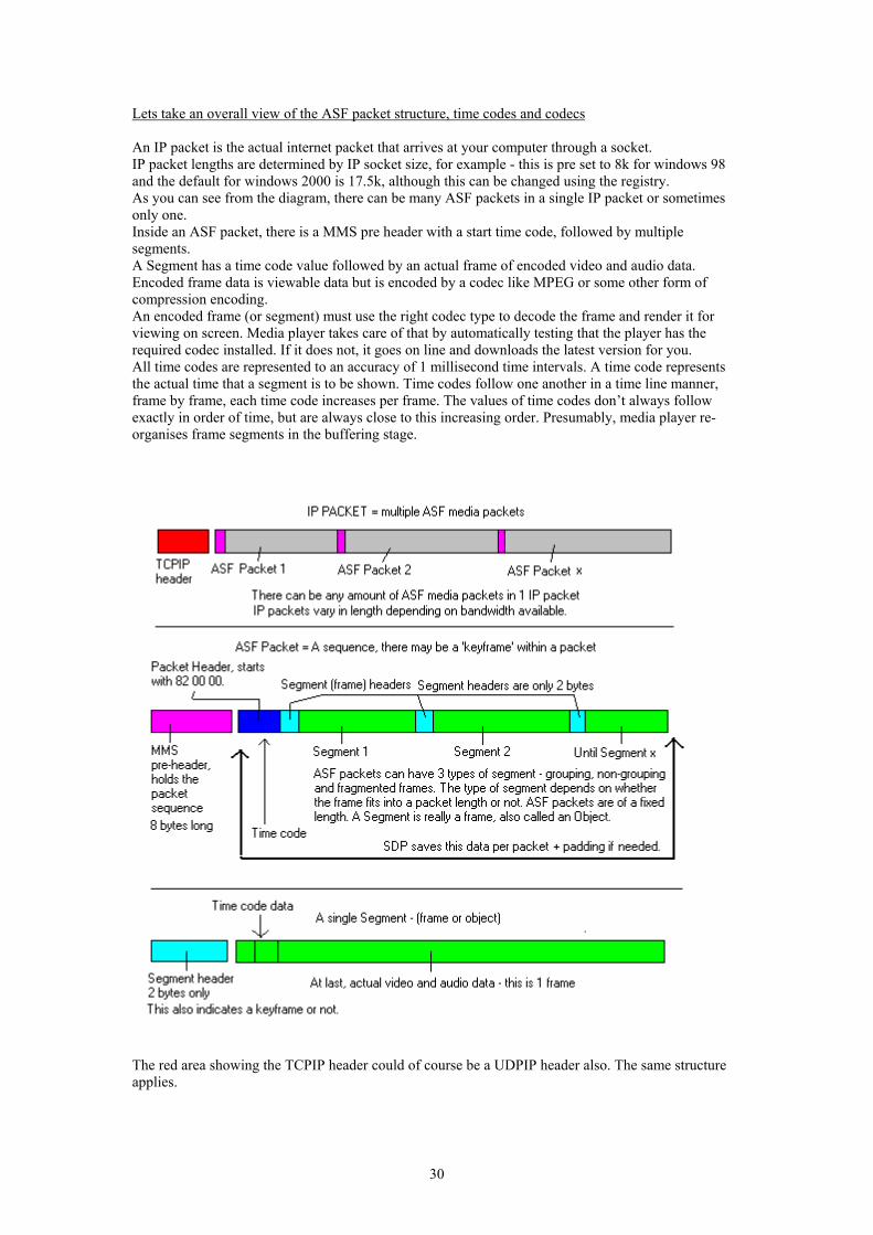
Lets take an overall view of the ASF packet structure, time codes and codecs An IP packet is the actual internet packet that arrives at your computer through a socket. IP packet lengths are determined by IP socket size, for example - this is pre set to 8k for windows 98 and the default for windows 2000 is 17.5k, although this can be changed using the registry. As you can see from the diagram, there can be many ASF packets in a single IP packet or sometimes only one. Inside an ASF packet, there is a MMS pre header with a start time code, followed by multiple segments. A Segment has a time code value followed by an actual frame of encoded video and audio data. Encoded frame data is viewable data but is encoded by a codec like MPEG or some other form of compression encoding. An encoded frame (or segment) must use the right codec type to decode the frame and render it for viewing on screen. Media player takes care of that by automatically testing that the player has the required codec installed. If it does not, it goes on line and downloads the latest version for you. All time codes are represented to an accuracy of 1 millisecond time intervals. A time code represents the actual time that a segment is to be shown. Time codes follow one another in a time line manner, frame by frame, each time code increases per frame. The values of time codes don’t always follow exactly in order of time, but are always close to this increasing order. Presumably, media player re-organises frame segments in the buffering stage.
The red area showing the TCPIP header could of course be a UDPIP header also. The same structure applies.
30
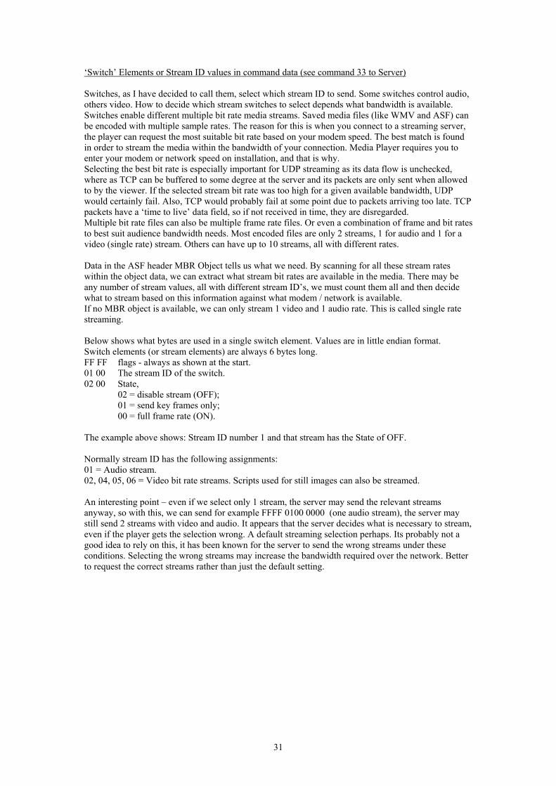
‘Switch’ Elements or Stream ID values in command data (see command 33 to Server) Switches, as I have decided to call them, select which stream ID to send. Some switches control audio, others video. How to decide which stream switches to select depends what bandwidth is available. Switches enable different multiple bit rate media streams. Saved media files (like WMV and ASF) can be encoded with multiple sample rates. The reason for this is when you connect to a streaming server, the player can request the most suitable bit rate based on your modem speed. The best match is found in order to stream the media within the bandwidth of your connection. Media Player requires you to enter your modem or network speed on installation, and that is why. Selecting the best bit rate is especially important for UDP streaming as its data flow is unchecked, where as TCP can be buffered to some degree at the server and its packets are only sent when allowed to by the viewer. If the selected stream bit rate was too high for a given available bandwidth, UDP would certainly fail. Also, TCP would probably fail at some point due to packets arriving too late. TCP packets have a ‘time to live’ data field, so if not received in time, they are disregarded. Multiple bit rate files can also be multiple frame rate files. Or even a combination of frame and bit rates to best suit audience bandwidth needs. Most encoded files are only 2 streams, 1 for audio and 1 for a video (single rate) stream. Others can have up to 10 streams, all with different rates. Data in the ASF header MBR Object tells us what we need. By scanning for all these stream rates within the object data, we can extract what stream bit rates are available in the media. There may be any number of stream values, all with different stream ID’s, we must count them all and then decide what to stream based on this information against what modem / network is available. If no MBR object is available, we can only stream 1 video and 1 audio rate. This is called single rate streaming. Below shows what bytes are used in a single switch element. Values are in little endian format. Switch elements (or stream elements) are always 6 bytes long. FF FF flags - always as shown at the start. 01 00 The stream ID of the switch. 02 00 State,
02 = disable stream (OFF); 01 = send key frames only; 00 = full frame rate (ON).
The example above shows: Stream ID number 1 and that stream has the State of OFF. Normally stream ID has the following assignments: 01 = Audio stream. 02, 04, 05, 06 = Video bit rate streams. Scripts used for still images can also be streamed. An interesting point – even if we select only 1 stream, the server may send the relevant streams anyway, so with this, we can send for example FFFF 0100 0000 (one audio stream), the server may still send 2 streams with video and audio. It appears that the server decides what is necessary to stream, even if the player gets the selection wrong. A default streaming selection perhaps. Its probably not a good idea to rely on this, it has been known for the server to send the wrong streams under these conditions. Selecting the wrong streams may increase the bandwidth required over the network. Better to request the correct streams rather than just the default setting.
31
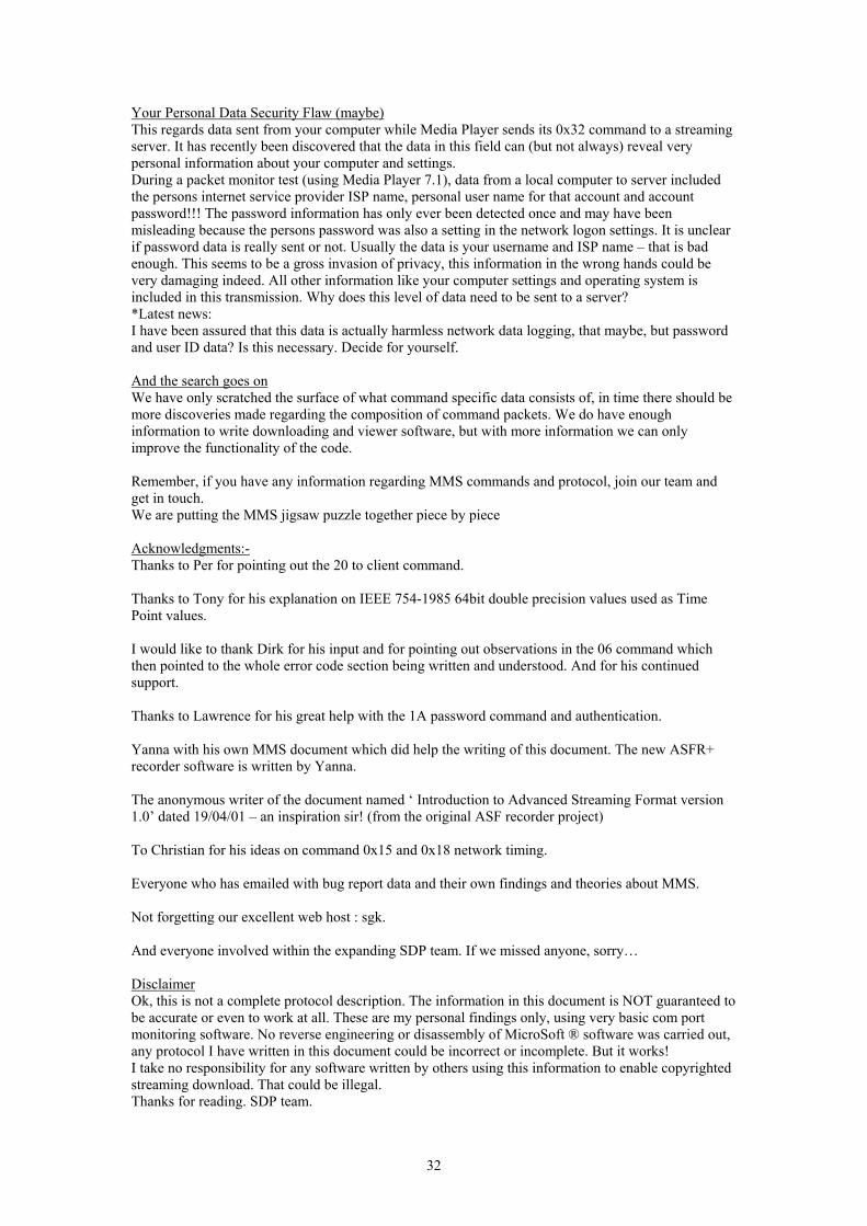
Your Personal Data Security Flaw (maybe) This regards data sent from your computer while Media Player sends its 0x32 command to a streaming server. It has recently been discovered that the data in this field can (but not always) reveal very personal information about your computer and settings. During a packet monitor test (using Media Player 7.1), data from a local computer to server included the persons internet service provider ISP name, personal user name for that account and account password!!! The password information has only ever been detected once and may have been misleading because the persons password was also a setting in the network logon settings. It is unclear if password data is really sent or not. Usually the data is your username and ISP name – that is bad enough. This seems to be a gross invasion of privacy, this information in the wrong hands could be very damaging indeed. All other information like your computer settings and operating system is included in this transmission. Why does this level of data need to be sent to a server? *Latest news: I have been assured that this data is actually harmless network data logging, that maybe, but password and user ID data? Is this necessary. Decide for yourself. And the search goes on We have only scratched the surface of what command specific data consists of, in time there should be more discoveries made regarding the composition of command packets. We do have enough information to write downloading and viewer software, but with more information we can only improve the functionality of the code. Remember, if you have any information regarding MMS commands and protocol, join our team and get in touch. We are putting the MMS jigsaw puzzle together piece by piece Acknowledgments:- Thanks to Per for pointing out the 20 to client command. Thanks to Tony for his explanation on IEEE 754-1985 64bit double precision values used as Time Point values. I would like to thank Dirk for his input and for pointing out observations in the 06 command which then pointed to the whole error code section being written and understood. And for his continued support. Thanks to Lawrence for his great help with the 1A password command and authentication. Yanna with his own MMS document which did help the writing of this document. The new ASFR+ recorder software is written by Yanna. The anonymous writer of the document named ‘ Introduction to Advanced Streaming Format version 1.0’ dated 19/04/01 – an inspiration sir! (from the original ASF recorder project) To Christian for his ideas on command 0x15 and 0x18 network timing. Everyone who has emailed with bug report data and their own findings and theories about MMS. Not forgetting our excellent web host : sgk. And everyone involved within the expanding SDP team. If we missed anyone, sorry… Disclaimer Ok, this is not a complete protocol description. The information in this document is NOT guaranteed to be accurate or even to work at all. These are my personal findings only, using very basic com port monitoring software. No reverse engineering or disassembly of MicroSoft ® software was carried out, any protocol I have written in this document could be incorrect or incomplete. But it works! I take no responsibility for any software written by others using this information to enable copyrighted streaming download. That could be illegal. Thanks for reading. SDP team.
32