Embed Size (px)
Citation preview

MMMnnnRRROOOAAADDD DDDiiissstttrrreeessssss MMMaaappppppiiinnnggg MMMaaannnuuuaaalll GIS/GPS
MnROAD
Mn/DOT Office of Materials
Draft Report
Agueda Guerra Cassandra O’Neal
Ruth Roberson Bruce Tanquist

MnROAD Distress Mapping Manual GIS/GPS
The Mn/DOT Office of Materials, in an attempt to optimize the process of data
collection and data analysis for the distress surveys in the MnROAD research facility,
has developed a method that uses a Global Positioning System (GPS) and a
Geographic Information System (GIS) software called ArcMap to make accurate distress
measurements in the field and to manipulate and analyze the data in the office. The
adoption of the GPS and GIS tools will convert the distress surveys in a quantitative
process, which will make easier to develop theories and draw conclusions about the
data collected in MnROAD.
This report contains a detailed procedure of how to use the GPS and GIS tools for
distress surveys purposes. It includes: how to use the GPS unit, how to manipulate the
data in the office, how to upload the data to the desktop PC and hand-held computer,
and how to use the hand-held computer for surveys in the field.

3
MnROAD Distress Mapping Manual GIS/GPS
Table of Content
Using the GPS unit Page
1. 24 Hours Prior To Field Use 4
1.1. Inventory Equipment 4 1.2. Charge Batteries 4
2. Assembling the Unit 4
3. Turning the Receiver On 4 4. Setting Up the Controller 5 5. Surveying 5 6. Turning the Equipment Off 6 Working at the Office 1. Transferring new data to the PC 7
1.1. Uploading the data in the Computer (Trimble) 7 1.2. Tracing the cracks 9 1.3. Exporting the data from Trimble to ArcMap 10 1.4. Importing the data in ArcMap 11
2. Filling the Attribute table 14
3. Digitalizing the hand-drawn maps 20 4. Updating the ArcPad File 27 Using the Palm Pilot in the Field 1. Editing the ArcPad file
1.1. Manipulating a Shapefile 32 1.2. Creating Bookmarks 34 1.3. Editing cracks in ArcPad 36 1.4. Transferring Files from the Palm Pilot to the Desktop PC 40

4
Using the GPS unit 1. 24 Hours Prior To Field Use
1.1. Inventory Equipment
Trimble Ranger Controller (Windows CE hand-held computer) Trimble 5800 Receiver Nokia 6600 cell phone (data plan only – no voice) Hand-held Computer (Palm Pilot) Tripod assembly with bracket for controller Dual battery charger for receiver batteries FRIWO transformers (1 each for controller and dual battery charger) AC and car chargers for cell phone Bluetooth adapter (plugs into 26-pin port on top of controller) USB cable with 26-pin port adapter for data transfer between controller and PC
(Bluetooth adapter must be removed to transfer data)
1.2. Charge Batteries
Charge all 4 batteries: 2 for the receiver, 1 for the controller, 1 for the cell phone Batteries should not be charged for extended periods of time Remove battery from the receiver when not in use Bluetooth adapter must be plugged in to the controller There is a car charger for the phone
2. Assembling the Unit
Step 1 Place battery in the receiver Step 2 Attach radio antenna to receiver. (This is not required for Bluetooth
connections) Step 3 Screw the upper portion of the tripod (black rod with level) into the
receiver Step 4 Check the condition of the tip on the lower portion of the tripod (black rod
with point on end), make sure that the tip is not damaged Step 5 Screw the upper portion and lower portion of the tripod together (the
receiver, level, and quick-adjust buttons should all be facing one direction)
Step 6 Place the controller in the quick-release bracket Step 7 Attach the quick-release bracket to the clamp on the upper portion of the
tripod (make sure the small metal piece is aligned with an opening to secure the controller in place, and the controller is facing the same direction as the receiver, level and quick-adjust buttons) Step 8 Place Bluetooth adaptor on the top of the controller (if not already on)
3. Turning the Receiver On
Step 1 Turn the cell phone on (press red button on top for 2 seconds) Step 2 Press the green power button on the receiver once Step 3 The green power light should stay on, the yellow satellite light will blink

5
quickly as it locates satellite signals, and then blink slowly once it locates 3 or more signals. After the satellite light starts to blink slowly move on to
Setup Controller 4. Setting Up the Controller
Step 1 Press green Power button Step 2 Double-click on Survey Controller Step 3 Click on Files to create a new job or open an existing job
Give a descriptive name like “mnrc01072105” = MnROAD cell 1 on July
21, 2005 The job name should be described by the place/cell #/mm/dd/yy There are 3 digits available for the place (mnr = MnROAD) There are 2 digits available for the cell #, after the letter “c” There are 2 digits available for the month, day, and year If the cell # does not apply (for example out on a job site), then there are
6 digits available for a descriptive place Record job name and surveyor name in the orange book Coordinate System – 15 North (UTM) This should already be set. Check the settings by clicking on the
”Coord. Sys.” button Select from library System:UTM Zone: 15 North Datum: WGS 1984 (same as NAD 1983) Use geoid model: Geoid03_Grid3 (Grid 2 is for the Western third of
Minnesota) Coordinates: Grid Project height: 295.000m (this is the appropriate height for MnROAD,
this value changes from project to project. Units (Dist.): Meters Cogo settings: Ground Scroll down to type in other details
5. Surveying
Step 1 Click Survey…VRS NTRIP…Start Survey Step 2 Press “Yes” on the cell phone when it is enquired, wait a few seconds and
press “Yes” again. The survey controller will go through a series of steps connecting to the modem and authenticating the connection
Step 3 A data source list is created. Select MNDOT_RTKNet CMR+…From the list by clicking on it Step 4 Enter in User Name: mmm01 and Password: 0135 Step 5 Select Enter Step 6 Select Accept Step 7 The Survey Controller will now establish a connection to Mn/DOT’s VRS
Server and proceed to start the survey Step 8 Click on Survey…Measure points

6
Step 9 Type a descriptive name like “a06hcr01pt01“ for cracks
The point name should be described by the road material/type of crack #/severity level/crack #/point #
There is 1 digit for the type of material, “a” = asphalt and “c” = concrete. If there is a different type of material, code it in the orange book.
There are 2 digits available for the type of crack #, the codes for the type of crack # are displayed in the distress type manual
There is 1 digit for the level of severity (l = low, m = moderate, or h = high)
There are 2 digits available for the crack #, after the letters “cr” There are 2 digits available for the point #, after the letters “pt” The codes for the point name are described in detail in the distress type
manual The next point will automatically increment to “a06hcr01pt02”
Step 5 If not measuring cracks, type a descriptive name and record it in the
orange book (if there are a series of points that should be connected, the descriptive name should have two number digits at the end of the name)
Step 6 Level the receiver Step 7 Click the Measure button in the lower-right corner of the screen Step 8 When the precision at or below 0.010m horizontal and 0.015m vertical,
click Store and wait for verification Step 9 Move to next point and repeat step 5 - 7 Step 10 To start measuring the next crack, adjust the road material, type of crack
#, and severity level. Add 1 to the crack number, and reset the point number to 01: “a06mc02pt01”
6. Turning the Equipment Off
Step 1 Click Survey…End survey Step 2 Power down the receiver Step 3 Turn off controller (press green power button once) Step 4 Turn off cell phone (hold down red button on top for 2 seconds) Step 5 Place controller in yellow bag Step 6 Disassemble the tripod Step 7 Take the battery out of the receiver Step 8 Before leaving the field, check to make sure all equipment is accounted
for and securely put away

7
Working at the Office 1. Transferring new data to the PC
1.1. Uploading the data in the Computer (Trimble) Step 1 Remove Bluetooth adapter from top of controller Step 2 Plug the flat end of the USB transfer cable into USB port in the front of the
PC and the other end into the Trimble adapter and plug that into 26 pin port on the top of the controller Step 3 Click Yes on the controller when prompted to connect to desktop Step 4 Select Guest Partnership and Next on the PC when prompted to set up a
Partnership (See Fig. 1)
Figure 1
Step 5 Start TGOffice (square yellow icon on the desktop) Step 6 Click File… New Project Step 7 Give the project a name that corresponds to the survey name on the
controller Step 8 Select Metric in the Template menu of the New Project window
(See Fig. 2)

8
Figure 2
Step 9 When Project Properties window comes up, click OK (defaults should be
okay) Step 10 Click File… Import… Survey Devices… OK. (See Fig. 3)
Figure 3
Step 11 Select Survey Controller (TSCe) on ActiveSync and click Open.
(See Fig. 4)

9
Figure 4
Step 12 Select the survey file(s) you want to import and click Open (hold down the
Ctrl key to select multiple files) Step 13 When prompted for a Geoid model, select "03_Minnesota_Central_East"1 Step 14 Click View…Point Labels…check the box next to Name… OK
1.2. Tracing the cracks
Step 1 Click on Reports… Additional Reports… Points… OK Step 2 Click View… Plan Step 3 Click View… Tool Bars… CAD. Step 4 On the plan CAD tool bar click on the insert lines icon (diagonal straight
line) Step 5 Using the Points Report as a reference, connect the points from crack 1
(See Fig. 5)
1 If this geoid model is not on the list, it needs to be added to the Current.csd file. Close Trimble Geomatics Office. Copy "G03U02.GGF" and "G03U03.GGF" from "R:\Design\GIS\Trimble Projects\Geoid Models" into "C:\Program Files\Common Files\Trimble\GeoData". Open Trimble Geomatics Office without opening a project. Select "Utilities…Coordinate System Manager". Then "Edit…Add Geoid Model". In the "Name" box, type "03_Minnesota_West". In the "File name" box, select "G03U02.GGF" from the list and click "OK". Repeat with "03_Minnesota_Central_East" (G03U03.GGF). These Geoid models can also be downloaded as self-extracting executables from: http://www.trimble.com/geoid_ts.asp (Click on "Geoid 03 Continental US" and download "Geoid 03 Region 02" and Geoid 03 Region 03").

10
Figure 5
Step 6 Close out of Insert Linework when finished with crack 1 Step 7 Reopen insert lines icon to connect points in crack 2 Step 8 Repeat Steps 5 – 7 until all the cracks in the job are turned into lines
instead of points 1.3. Exporting the data from Trimble from Trimble to ArcMap
Step 1 Click File… Export and select the Shape tab Step 2 Select Arcview shape files – points & lines (*.dbf, *.shp, *.shx) and OK.
(See Fig. 6) Step 3 Copy the folder with the new project name from C:\Trimble Geomatics
Office\Projects to R:\Design\GIS\MnROAD\Trimble Projects using ArcCatalog
Figure 6

11
1.4. Importing the data in ArcMap
Step 1 Start ArcMap and open the file where you want to include the new data Step 2 Make sure that the Standard menu is open (View… Toolbars…
Standard) Click Add Data (The yellow square with a black plus sign) or click File…Add data Step 3 Browse for the location of the new project. It should be found in
R:\Design\GIS\MnROAD\Trimble Projects. Click on it, and then click on the Export folder. Select the files Default and Default-Area and click Add Step 4 Make sure that the Table of Contents Window is open. If not, click
Window… Table of Contents. Layers named Default and default-Area will appear in the Table of Contents Step 5 Right click on the Layer Default in the Table of Contents. Click
Data…Export Data. (See Fig. 7) Step 6 Browse to the final location of the shape files in the “R” drive. It should
be: R:\Design\GIS\MnROADProjects\MnROAD Crack Maps Fall 2005. Type the name of the layer in the Saving Data window: GPS Cell## (## is the number of the corresponding cell). Click Save. (See Fig. 8)
Step 7 Select “Export All Features” and “Use the same Coordinates System as this layer’s source data” in the export Data window. Click OK (See Fig. 9)
Figure 7

12
Figure 8
Figure 9
Step 8 Click “Yes” when prompted to “add the exported data to the map as a
layer”. A layer called “GPS Cell##” will appear in the Table of Contents window. (See Fig. 10)

13
Figure 10
Step 9 Right-click on the layer Default and click Remove. (See Fig. 11)
Figure 11
Step 10 Repeat steps 5 to 9 for the Default-Area layer. Name the shape file as
“GPS Cell##p”
14
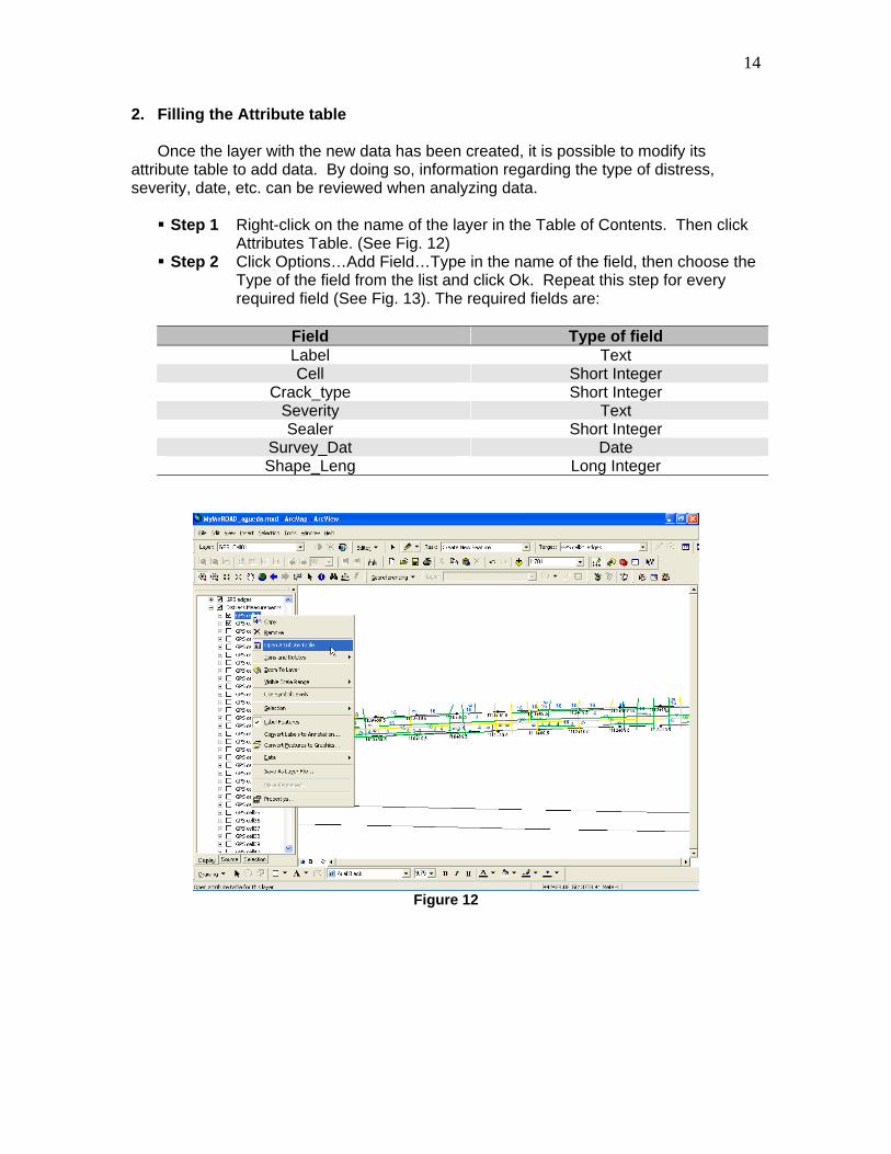
2. Filling the Attribute table
Once the layer with the new data has been created, it is possible to modify its attribute table to add data. By doing so, information regarding the type of distress, severity, date, etc. can be reviewed when analyzing data.
Step 1 Right-click on the name of the layer in the Table of Contents. Then click
Attributes Table. (See Fig. 12) Step 2 Click Options…Add Field…Type in the name of the field, then choose the
Type of the field from the list and click Ok. Repeat this step for every required field (See Fig. 13). The required fields are:
Field Type of field Label Text Cell Short Integer
Crack_type Short Integer Severity Text Sealer Short Integer
Survey_Dat Date Shape_Leng Long Integer
Figure 12
15
Figure 13
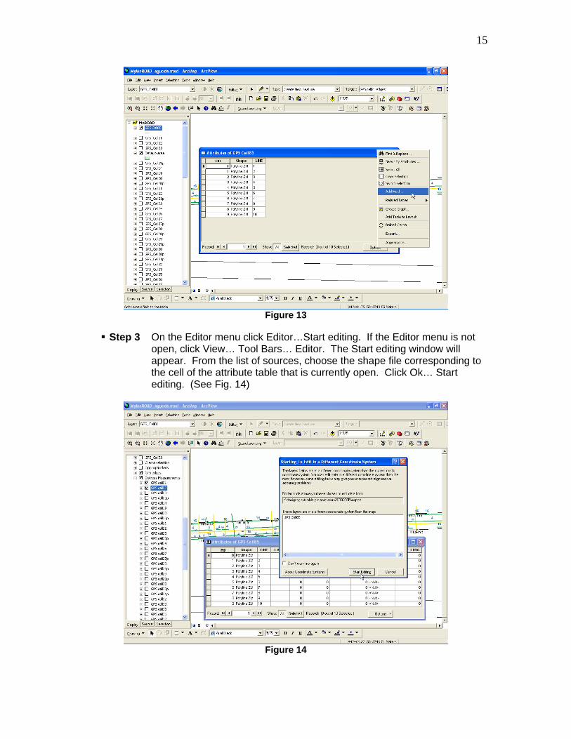
Step 3 On the Editor menu click Editor…Start editing. If the Editor menu is not
open, click View… Tool Bars… Editor. The Start editing window will appear. From the list of sources, choose the shape file corresponding to the cell of the attribute table that is currently open. Click Ok… Start editing. (See Fig. 14)
Figure 14
16
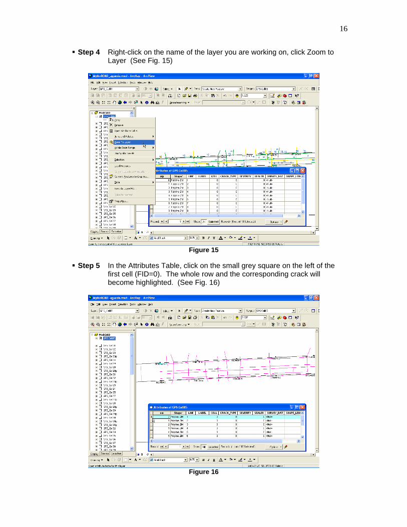
Step 4 Right-click on the name of the layer you are working on, click Zoom to Layer (See Fig. 15)
Figure 15
Step 5 In the Attributes Table, click on the small grey square on the left of the
first cell (FID=0). The whole row and the corresponding crack will become highlighted. (See Fig. 16)
Figure 16

17
Step 6 Use the Tool Zoom In to see clearly the crack in the display area Step 7 Start TGOffice (square yellow icon on the desktop) and open the file
corresponding to the cell you are working on. Arrange the windows: TGOffice, ArcMap, and Attributes of GPS Cell##, so the three of them are completely visible on the screen. (See Fig. 17) Step 8 Put the cursor close to a point of the selected crack. A tag like:
“a06hcr01pt02” will appear on the point. This tag indicates the material of the cell, the type of distress, the severity, the number of the crack, and the number of the point. With this information is possible to fill the attributes table. The survey date is in the name of the TGOffice file. The Shape_leng needs to be measured in TGOffice. (See Fig. 17) Step 9 To measure the length of the crack. Go to TGOffice. Click Survey…
Measure. Put the cursor close to the first point of the crack you want to measure and wait until the tag appears, click on the point and then do the same with the other points of the crack. The length of the crack appears in the window measure as: distance(ellipsoid). Type this value in the Shape_leng field of the attributes table for the corresponding crack.
Figure 17
Step 10 Repeat steps 5 to 9 for every crack Step 11 After completing the attributes tables with all the information, click
Editor… Stop Editing. Click “Yes” when prompted to save the changes Step 12 Close the TGOffice and Attributes Table windows and maximize the
ArcMap widow Step 13 Double-click on the name of the layer. The Layer Property window will
open Step 14 Select the Symbology tab and click on Categories. (See Fig. 18)

18
Figure 18
Step 15 Select Severity in the Value Field menu and then click Add All Values
(See Fig. 19)
Figure 19
Step 16 Deselect the All Other Values check box. Click on high and move it down
using the arrows on the right side of the window (See Fig. 20)

19
Figure 20
Step 17 Double-click on the line next to the word “low”. The Symbol selector
window will appear Step 18 Click on the color selector in the Options menu. Then select the A24
Green and a width of 1.5. Then click OK. (See Fig. 21)
Figure 21
Step 19 Repeat Step 17 and 18 for mod and high using the following standards

20
Cracks Severity Color Width
low Green (A24) 1.5 mod Yellow (A10) 1.5 high Red (A00) 1.5 N/A Blue (A15) 1.5
Patches
Severity Color Outline Color Outline Width low Tzavorite Green Green (A24) 0.4 mod Yucca Yellow Yellow (A10) 0.4 high Rose Quartz Red (A00) 0.4
Step 20 Click on the Labels tab. Check the Label Features in this Layer box.
Select Crack Type from the Text String menu. Click OK. (See Fig. 22)
Figure 22
Step 21 Save editing changes
3. Digitalizing the Hand-Drawn Maps
Step 1 Start ArcMap and open the file where you want to include the new data and navigate to the area where the data needs to be included Step 2 Make sure that the Standard menu is open (View… Toolbars…
Standard). Click Add Data (The yellow square with a black plus sign) or click File…Add data

21
Step 3 Browse for the location of the scanned hand-drawn maps. It should be at R:\Design\GIS\MnROAD\DATA\DISTRESS MAP. Select the file and click Add Step 4 Make sure that the Data Frame is not rotated. Click View… Data Frame
Properties. Type “0” (zero) in the Rotation box. Click OK Step 5 Make sure that the Georeferencing menu is open (View… Toolbars…
Georeferencing) Click Georeferencing …Fit to Display (See Figure 23)
Figure 23
Step 6 Click Rotate in the Georeferencing Menu (See Figure 24)

22
Figure 24
Step 7 Click on the scanned image and rotate it until it is aligned with the ArcMap
drawing. (See Figure 25)
Figure 25
Step 8 Click Add Control Points (See Figure 26)

23
Figure 26
Step 9 Click on one corner of the cell in the scanned image and then click on the
corresponding corner in the ArcMap drawing. The stations need to match up. The scanned image will move to that point (See Figure 27)
Figure 27
Step 10 Repeat Step 9 for the other 3 corners. The scanned image will fit the
ArcMap drawing (See Figure 28)

24
Figure 28
Step 11 Open the Attribute table of the corresponding cell (See Figure 29)
Figure 29
Step 12 Click Editor… Start Editing. Browse for the corresponding cell. Click
OK…Start Editing (See Figure 30)

25
Figure 30
Step 13 Click Sketch Tool (See Figure 31)
Figure 31

26
Step 14 Click on the beginning point of a crack that needs to be added to ArcMap. Trace the crack by clicking at points where the crack bends and curves, once the crack is fully traced double click at the end. Now a new feature is created. Check at the bottom of the attribute table for the new feature. (See Figure 32)
Figure 32
Step 15 Fill the attribute table with the information corresponding to the new crack Step 16 Repeat steps 13-15 for the other new cracks in the scanned image Step 17 If a crack on the scanned image has changed its severity (ex. low to
moderate), highlight the crack by clicking on it. Make sure to only highlight one crack at a time. Step 18 Go to the tool bar and click edit and scroll down to click copy. Step 19 Go to the tool bar and click edit and scroll down to click paste. Step 20 In the attribute table place the correct severity and survey date on the
newly added crack. Step 21 After digitalizing all the cracks of that scanned image, remove the image
from the file. To do this right-click on the name of the image in the Table of Contents and then click Remove (See Figure 33)

27
Figure 33
Step 22 Repeat steps 3-21 until all the segments of the cell are complete
4. Updating the ArcPad file In order to export the layers from ArcMap to an ArcPad project, it is necessary to install ArcPad onto the desktop PC to get the ArcPad Tools.
Step 1 Install ArcPad 6.0 onto your Palm Pilot and desktop PC Step 2 If necessary, install M.S. ActiveSync on your desktop PC Step 3 In ArcMap, go to View… Toolbars and choose Customize (See Figure 34)

28
Figure 34
Step 4 A Customize window appears. In this window, choose to Add from file
(See Figure 35)
Figure 35
Step 5 Navigate to this directory, C:/Program Files/ArcPad/apTools8/, and
choose to Open apTools8.dll (See Figure 36)

29
Figure 36
Step 6 An Added Objects window appears after opening the *.dll file Step 7 Click OK in the Added Objects window Step 8 Close the Customize window Step 9 Go to View…Toolbars, and choose ArcPad Tools. Once chosen, an
ArcPad Tools toolbar appears (See Figure 37)
Figure 37

30
Step 10 Go to Windows Explorer and create a folder, where the exported layers and ArcPad map document will be saved Step 11 Go back to the ArcMap project. Step 12 Prompt the ArcPad Map Wizard by clicking on the ArcPad Map
Wizard icon (See Figure 38)
Figure 38
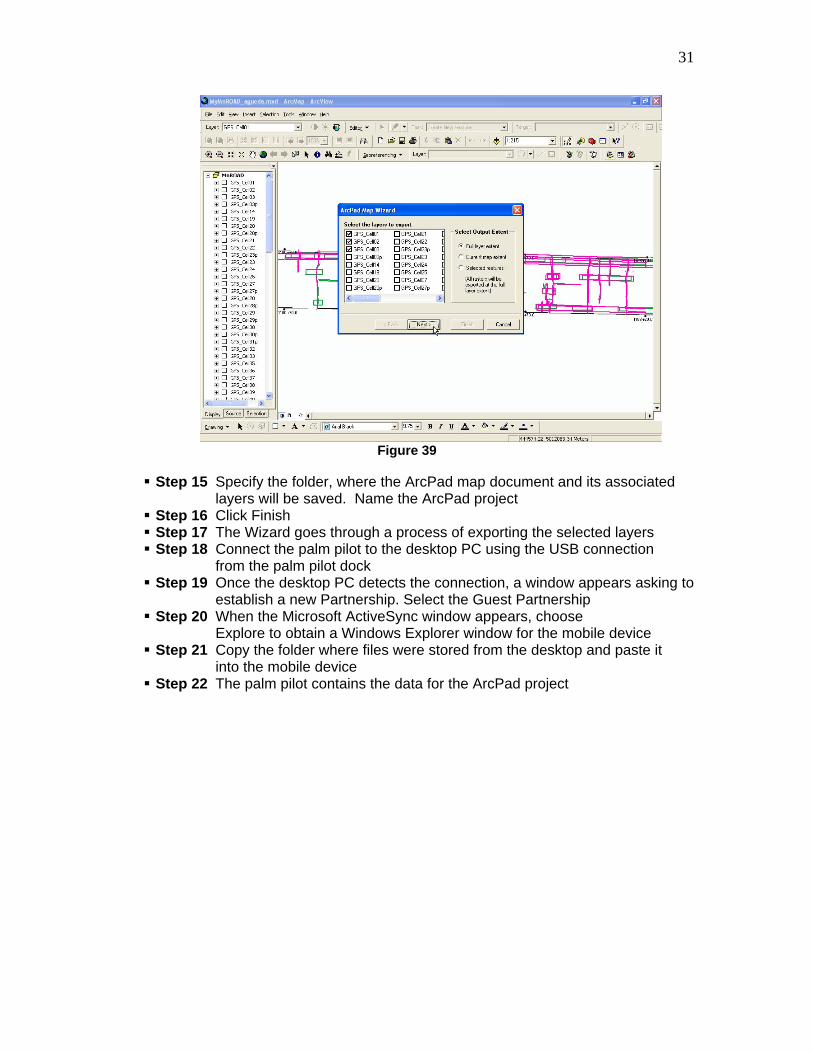
Step 13 Click Next Step 14 Select the layers to be exported by placing a check mark by them,
and click Next (see Figure 39)
31
Figure 39
Step 15 Specify the folder, where the ArcPad map document and its associated
layers will be saved. Name the ArcPad project Step 16 Click Finish Step 17 The Wizard goes through a process of exporting the selected layers Step 18 Connect the palm pilot to the desktop PC using the USB connection
from the palm pilot dock Step 19 Once the desktop PC detects the connection, a window appears asking to
establish a new Partnership. Select the Guest Partnership Step 20 When the Microsoft ActiveSync window appears, choose
Explore to obtain a Windows Explorer window for the mobile device Step 21 Copy the folder where files were stored from the desktop and paste it
into the mobile device Step 22 The palm pilot contains the data for the ArcPad project

32
Using the Palm Pilot in the Field
1. Editing the ArcPad file
1.1 Manipulating a Shapefile Step 1 Open ArcPad on the palm pilot Step 2 Click the arrow to the right of the Open file icon and choose Open
Map (see Figure 40)
Figure 40
Step 3 Select the ArcPad map document created in ArcMap Step 4 Click on the Layers icon to obtain a Layers window (See Figure 41)
Figure 41

33
Step 5 Highlight the layer that is going to be modified (See Figure 42)
Figure 42
Step 6 Click on the Layer Attributes icon in the Layers window to obtain a Layer
Properties window. Click on the Labels tab (See Figure 43)
Figure 43
Step 7 This window must show the same properties of the original ArcMap layer.

34
Step 8 Place a check mark in the two boxes directly to the right of the layer that is going to be used. By doing this, the Identify icon can be used to identify features by clicking on them in the map display, and the Select icon can be used to modify the features’ properties. (See Figure 44)
Figure 44
Step 9 Click OK to the Layers window
1.2 Creating Bookmarks: Bookmarks can be set and used to zoom directly to a pre-defined area. Step 1 Use tools to navigate to an area where the bookmark needs to be placed
(Zoom In tool, Pan, Zoom Out, Fixed Zoom In, Fixed Zoom Out) Step 2 Once zoomed to the area where the bookmark will be placed, click on the
arrow to the right of the Previous Extent icon. Choose Create Bookmark from the dropdown menu (See Figure 45)

35
Figure 45
Step 3 Name the bookmark and click OK (See Figure 46)
Figure 46
Step 4 The bookmarks will be visible choices when Zoom to bookmark is chose
under the same dropdown menu (See Figure 47)

36
Figure 47
1.3 Editing Cracks in ArcPad
Step 1 Click on the Layers icon to obtain a Layers window (See Figure 48)
Figure 48

37
Step 2 Place a check mark in the two boxes directly to the right of the layer that is going to be used. So, the Identify icon and the Select icon are activated. (See Figure 49)
Figure 49
Step 3 Click OK to the Layers window Step 4 To get information about a feature, Click on the Information icon and then
click on the feature (See Figure 50)

38
Figure 50
Step 5 A window with the information about the feature will appear (See Figure
51)
Figure 51
Step 6 To change the properties of the feature, click on the Select icon and then
double-click on the feature (See Figure 52)
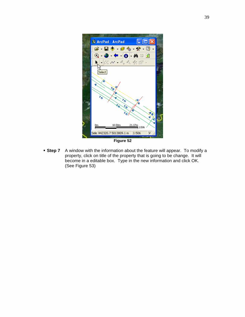
39
Figure 52
Step 7 A window with the information about the feature will appear. To modify a
property, click on title of the property that is going to be change. It will become in a editable box. Type in the new information and click OK. (See Figure 53)

40
Figure53
1.4 Transferring Files from the Palm Pilot to the Desktop PC
It is a simple process to import the shapefiles created in the field to a desktop GIS. Use Microsoft ActiveSync to establish a connection between the Palm Pilot and the desktop PC. Step 1 Connect the Palm Pilot to the desktop PC using the USB connection on
the Palm Pilot dock. Step 2 If a partnership does not exist between this mobile device and the PC,
choose to establish a guest partnership Step 3 When the Microsoft ActiveSync window appears, click Explore, the
Windows Explorer for the mobile device appears on the desktop PC. Step 4 Copy the folder where all the data is stored for the GPS exercise and
paste it onto the desktop PC Step 5 Add the new shapefiles to the ArcMap project