Embed Size (px)
Citation preview

National Radio Astronomy ObservatoryCharlottesville, Virginia
MMA MEMORANDUM # 90(also distributed as EDIR No. 292)
A STUDY OF MATERIALS FOR A BROADBAND MILLIMETER-WAVEQUASI-OPTICAL VACUUM WINDOW
A. R. Kerr, N. J. Bailey, D. E. Boyd and N. Horner
August 21, 1992
Introduction
Cryogenic millimeter-wave receivers require a low-loss vacuum windowthrough which the incoming beam can pass on its way to the cold feed horn.Thick dielectric plates have been used as windows, but their loss cancontribute significantly to the receiver noise temperature, and their usefulbandwidth is limited even when matching grooves or dielectric matching layersare used. A simpler approach, which has been in use for many years atBerkeley [1] and Caltech [2], is to use a thin sheet of mylar (polyethyleneterephthalate) as a vacuum window. Atmospheric pressure causes such a windowto balloon alarmingly, but the great strength and flexibility of mylar aresufficient in many applications so long as no sharp object pricks the window(in which event the results could be hazardous). Radiation cooling of themylar film by the cold innards of the dewar can cause condensation of water onthe outside of the window, which can contribute significant electrical loss.To prevent this, the mylar can be dried by air from a small fan.
This report describes a window in which a thin plastic film vacuumbarrier is supported by a thick slab of low density dielectric foam. Thedielectric foam bears the full atmospheric pressure, and also acts as aninfrared filter to reduce radiative cooling of the plastic film and radiativewarming of the cold contents of the dewar. This scheme was inspired by thewindow for circular waveguide described of Bradley and Norrod [3, 4], whichuses a plug of polystyrene foam inside the waveguide and a mylar film glued onthe atmospheric side of the window to prevent moisture absorption by the foamover long periods of time.
The Vacuum Barrier
Table I lists the properties of some plastic films which might besuitable for use as a vacuum barrier in the present application. The highstrength and low permeability to water vapor and atmospheric gases of theHR500/2S material make it appear the most attractive. This material,manufactured for food packaging by Hercules, Inc. [5], is a laminate ofbiaxially oriented polypropylene with 0.0001" layers of polyvinylidenechloride on both sides. It is available in 0.001" and 0.00075" thicknesses.
The water vapor and gas permeabilities of even the best of these filmsare not zero. However, experience at several observatories indicates thateven mylar windows, with their high water vapor transmission rate, aresatisfactory for extended periods of operation. This is presumably a result

2
of the natural ability of cryogenic systems to maintain a good vacuum bycryopumping. The window leak rate may be significant, however, for largewindows, or for multi-band receiver packages with many windows such as will beused on NRAO's proposed Millimeter Array. Just how much water and gas areceiver can cryopump before difficulties arise is not known. Accumulation ofice on cold quasi-optical components or inside feed horns may eventuallydegrade receiver performance, or an accumulation of frost may reduce thecryopumping capability of the system.
All the low loss plastic films we have tested have had substantial Heleak rates [6]. This may have serious long-term consequences in applicationswhere there is a high background level of He. It has been reported, forexample, that boil-off from a liquid He cooled bolometer caused a nearby 15 Kreceiver to warm up [7]. Such problems should be easy to avoid withappropriate ventilation, or venting of boiled off He.
Fig. 1 shows the theoretical insertion loss and return loss of severalthicknesses of film with εr = 3 (corresponding to mylar), as functions offrequency. Measurements of 1 mil and 2 mil mylar films at 230 and 260 GHz arealso shown, and are seen to agree reasonably with the theoretical values.Fig. 2 shows the measured insertion loss of some plastic film windows at 230and 260 GHz.
The Foam Support — Attenuation
Electrically, low density polystyrene foam is an almost ideal materialfor a millimeter-wave window. When the present work began in 1989, extrudedpolystyrene foam was available in several densities from Emerson & Cuming [8]as the Eccofoam PS series of materials, specified by relative dielectricconstant, and also from Dow [9] as their Styrofoam Hiload series of materials,specified by compressive strength. These materials were foamed using freongas. Because of its harmful effect on the atmosphere, freon was replacedaround 1989 with more benign gases (Dow now uses a hydro-chloro-fluorocarboncalled Isotron-142b). We have tested the newer materials from severalmanufacturers, and found them much too lossy for use in millimeter-wavewindows (typically 1 dB/in at 100 GHz). Recently, Emerson & Cuming havestopped selling the Eccofoam PS materials.
A suitable substitute for extruded polystyrene appears to be expandedpolystyrene, which has a visibly beaded structure and is commonly used for hotdrink cups and drink coolers. Expanded polystyrene is fabricated from beadsinitially containing the styrene monomer, benzene, and pentane as a blowingagent. The beads are "popped" in a vessel with high pressure steam. Thenewly formed foam contains a considerable amount of water from the steam, butthis diffuses away and the material stabilizes mechanically during a 90-dayageing period [10]. The beads come in several sizes. The samples we havetested from Radva Corporation [10] are made with ARCO Dylite size B beads;sizes X and T are smaller. A concern with this material was that themillimeter sized cell structure might cause scattering of millimeter-wavelength beams. However, measurements of Radva material (batches 3 and 4)indicate only about 1% scattered power from a 2"-thick sample at 260 GHz [11].
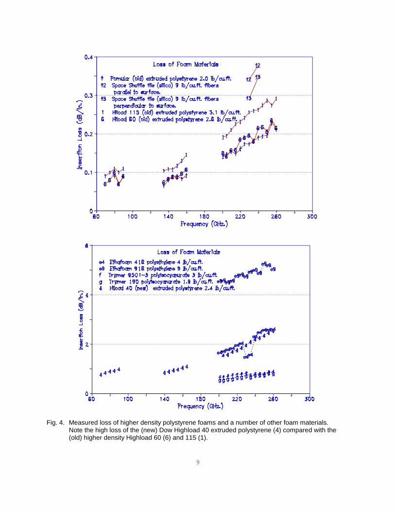
The insertion loss of a number of plastic foam materials is shown inFigs. 3 and 4. Fig. 3 shows the loss of expanded and (old) extrudedpolystyrene foams of density < 2.0 lb/ft3. It is clear that the density isthe critical parameter in determining the loss. In Fig. 4 the insertion lossis shown for higher density polystyrene samples, and for a number of otherfoam materials. The method of measurement is described in Appendix A.

3
We note, from Fig. 3, that the insertion loss of polystyrene foamappears to rise quite rapidly at frequencies approaching 300 GHz. It is notknown whether this is the skirt of a molecular resonance or is due to someother phenomenon. Further measurements will be made at higher frequencies inthe near future as appropriate equipment becomes available. For practicalpurposes, the increase in loss with frequency can be offset, at leastpartially, by using smaller diameter (and therefore thinner) windows at higherfrequencies.
The Foam Support — Mechanical
The shear strength of expanded polystyrene is shown as a function ofdensity in Fig. 5 [12]. The corresponding values for extruded polystyrene areclose to these. For minimum millimeter-wave loss, the window material shouldbe chosen to have the lowest density consistent with sufficient mechanicalstrength to support a pressure differential of one atmosphere with areasonable safety margin.
A circular window of diameter D in. and thickness t in., supported atits perimeter, when subjected to a differential pressure of 1 atm, willexperience a shear stress at its perimeter of 3.68 D/t lb/in2. For the windowdescribed below, D = 3 in, t = 1.125 in, and the shear stress is 9.8 lb/in2.Allowing a factor of two safety margin, the shear strength of the foam shouldbe � 20 lb/in2. From Fig. 5, this requires expanded polystyrene with adensity � 1.2 lb/ft3.
Destructive tests on windows with the above dimensions, made withexpanded polystyrene of density ~1.3 lb/ft3, have demonstrated a burstingpressure of ~3 atm.
Construction of a Broadband Vacuum Window
Fig. 6 shows the details of the broadband vacuum window. Thepolystyrene foam has a grid of small channels machined on the atmosphericpressure side, connected to two small through holes. This is to ensure thatgas or water vapor which leaks through the plastic film will find its wayrapidly to the inside of the dewar, whence it will be cryopumped by therefrigerator. Without the breather holes, molecules leaking through the filmwould diffuse through the foam. Because the vacuum side of the foam isradiatively cooled, molecules would freeze out when they reached asufficiently cold region of the foam. Over a long period, this could cause anincrease in the loss of a window, as was observed in the circular waveguidewindow of Norrod and Bradley [3] before they added a plastic barrier.
The polystyrene foam plug in Fig. 6 is glued into the aluminum tube.Prior to gluing, the aluminum surface is abraded with #80 sandpaper, and thencleaned with methanol followed by petroleum ether. The adhesive is applied toboth the inside of the aluminum tube and the outside of the polystyrene plug,which is then pushed into the tube. This procedure prevents voids formingduring assembly. Details of the adhesives, mix ratios, and curing schedulesare given in Appendix B.
The plastic film is glued to its aluminum ring under tension. This isaccomplished by first gluing the film to a larger ring, then placing thesmaller ring, coated with adhesive, in the middle. Prior to gluing, thealuminum rings are cleaned in methanol and petroleum ether, and the film inmethanol only. To provide tension, a 200 gm weight is placed on the smaller

4
ring during the cure. Details of the adhesives, mix ratios, and curingschedules are given in Appendix B.
Conclusion
A number of such windows have been made at NRAO over the last few years,and are in use in the lab and on all the SIS receivers on the 12-m Kitt Peaktelescope. Most of these have used low loss Eccofoam PS 1.04 extrudedpolystyrene, which is no longer available, and 0.001" or 0.00025" mylar vacuumbarriers. Newer windows, using expanded polystyrene and 0.00075" HR500/2Svacuum barriers, are now under long-term evaluation, and are expected to beused for all future receivers.
Acknowledgements
The authors are grateful to the many people who helped in this work. Inparticular, we thank the following people who supplied technical informationand/or samples of materials:
T. Anderson of Radva CorporationS. Forno of Hercules, Inc.J. Maruschak of Goddard Space Flight CenterA. Regianni of Emerson & CumingK. Renegar of Hibco PlasticsP. Richards of UC BerkeleyW. Spees of Du Pont, Inc.V. Vercoe of Dow ChemicalM. Wilson of Rockwell InternationalC. Wohlers of Garlock, Inc.P. Young of U.C. Industries
At NRAO, we thank: G. Behrens, D. Dillon, A. Marshall, S.-K. Pan, andG. Taylor for their help in testing the samples.
Sources of Materials
Material Manufacturer Supplier
Plastic Films
HR500/2S Hercules, Inc. ManufacturerWilmington, DE 19894
Mylar Du Pont Co. Elec. Insulation Suppl.Wilmington, DE 19898 Richmond, VA 23223
Cadillac Chem. & PlasticsVirginia Beach, VA 23455
Polypropylene Unknown Prof. P. L. RichardsU of CaliforniaBerkeley, CA 94720
Dielectric Foams
Eccofoam PS Emerson & Cuming ManufacturerCanton, MA 02021

5
Dylite Atlantic Richfield Co. Radva CorporationPhiladelphia, PA 19102 Radford, VA 24143
Hiload Dow Chemical Co. Samples from manufacturerMidland, MI 48674
Fomular U.C. Industries Samples from manufacturerParsippany, NJ 07054
Space Shuttle Tile Rockwell International Samples from manufacturerKennedy Space CenterFL 32815
Ethafoam Dow Chemical Co. Read PlasticsMidland, MI 48674 Rockville, MD 20852
Trymer Hibco Plastics Samples from manufacturerYadkinville, NC 27055
Adhesives
Eccobond Emerson & Cuming ManufacturerCanton, MA 02021
Scotch-Weld 3M Adhesives Waco Inc.Atlanta, GA 30360 Sandston, VA 23150
References
[1] D. P. Woody, "An Observation of the Submillimeter Background Radiation,"Ph.D. Thesis, University of California, Berkeley, 1975.
[2] B. N. Ellison and R. E. Miller, "A Low Noise 230 GHz SIS Receiver," Int.J. Infrared & Millimeter Waves, vol. 8, no. 6, pp. 609-625, June 1987.
[3] R. F. Bradley and R. D. Norrod, "Eccofoam as a Dewar Waveguide VacuumWindow," Electronics Division Technical Note No. 125, National RadioAstronomy Observatory, Charlottesville, VA 22903, Dec. 1984.
[4] R. F. Bradley, "Moisture Absorption by Eccofoam Dielectric Material,"Electronics Division Technical Note No. 131, National Radio AstronomyObservatory, Charlottesville, VA 22903, April 1985.
[5] Hercules, Inc., Wilmington, DE 19894.
[6] A. R. Kerr and Y. Taur, "Summary of WR-10 Waveguide Window Tests,"Internal Report, NASA/Goddard Institute for Space Studies, New York, NY10025, Sept. 1978.
[7] J. M. Payne, private communication.
[8] Emerson & Cuming, Canton, MA 02021.
[9] Dow Chemical Co., Midland, MI 48674.
[10] T. Anderson, Radva Corp., Radford, VA 24143, private communication,April 1992.
6
[11] J. W. Lamb, NRAO. Private communication, July 1992.
[12] ARCO Chemical Co., "Expanded Polystyrene Properties," AtlanticRichfield Co., Philadelphia, PA 19102, 1984.
[13] Du Pont Co., Polymer Products Dept, Industrial Films Div., Wilmington,DE 19898, Ideas of Mylar Polyester Film, Publication #E-41394(undated).
[14] Handbook of Plastics and Elastomers, C. A. Harper, Ed., McGraw-Hill,1975, pp. 1-101 to 1-102, 9-28. Note that the unit of permeability inTable 16 on p. 9-28 is gm/mil/(100 in2)/24 hrs, and not gm/mil/in2/24 hrsas stated.
[15] 3M Adhesives, Coatings and Sealers Division, St. Paul, MN 55144-1000.

7
TABLE I — PROPERTIES OF PLASTIC FILMS
PTFE Polyethylene Mylar Polypropylene(biax. orient.)
HR500/2Snote 3
Relative dielectric const.Tensile strength (psi)Water vapor trans. (note 1)Oxygen permeability (note 2)Nitrogen perm. (note 2)
2.1>15000.3--
2.26>1500
1500315
3.0>20000
1.861
2.55>12000
0.4120-
~2.6250000.3<1-
References: [5], [13], [14]Note 1: gm/100 sq.in./mil/24 hrs at 90% RH.Note 2: cc/100 sq.in./mil/24 hrs.Note 3: Biaxially oriented polypropylene with 0.0001" layers of polyvinylidene chloride on
both sides.
Fig. 1. Theoretical return loss and insertion loss vs. frequency for dielectric sheets with �r = 3 andthickness 0.00025", 0.005", 0.001", and 0.002". The points � and � are the measuredinsertion loss for 0.001" and 0.002" mylar.

8
Fig. 2. Measured loss of plastic films at 230 GHz (����) and 260 GHz (— — —).
Fig. 3. Measured loss of samples of expanded (����) and extruded (— — —) polystyrene foam ofseveral densities. (p1-p3) = Eccofoam PS 1.04 batch 1-3; (d1-d4) = Dylite batch 1-4. It isclear that the loss depends on density and not on whether the material is extruded orexpanded.
9
Fig. 4. Measured loss of higher density polystyrene foams and a number of other foam materials.
Note the high loss of the (new) Dow Highload 40 extruded polystyrene (4) compared with the(old) higher density Highload 60 (6) and 115 (1).

10
Fig. 5. Shear strength of expanded polystyrene as a function of density [12]. Extruded polystyrene issimilar.

11
Fig. 6. Construction of the broadband vacuum window. The plastic film vacuum barrier is supportedby the polystyrene foam plug. The small through holes "A" (1/16" dia.), connected to the gridof grooves in the upper surface of the foam, ensure that any gas molecules permeating thevacuum barrier are pumped away and do not condense at a cold region inside the foam.

12
APPENDIX A: Millimeter-Wave Loss Measurement
Measurements of insertion loss were made on samples of various films andfoams using the method described below. It was found that the skin on some ofthe foam samples caused a substantial reflection loss. Samples were thereforedeglazed by machining both sides where necessary.
Transmission loss measurements were made as shown in Fig. A1. Thereceiver output power was measured with the following loads in front of thereceiver: (i) the liquid nitrogen cold load (output power P1), (ii) thesample under test in front of the cold load (output power P2), and (iii) theroom temperature load (output power P3). The two Y-factors Y1 = P3/P1 andY2 = P2/P1 were calculated. If the sample is at room temperature, its loss isthen
1 - 1/Y1L = �������� , (A1)
1 - 1/Y2
which is independent of the hot and cold load temperatures. During themeasurements, the samples and the hot and cold loads were slightly inclined tothe axis of the receiver beam to avoid multiple reflections. Note that theloss given by eqn. (A1) includes the small reflection loss from the samples.
Fig. A1. Measurement of insertion loss of foam and film samples.

13
APPENDIX B: Adhesives Used in Constructing the Vacuum Window
Polystyrene to Aluminum
Eccobond 45 (Clear) epoxy adhesive [8].
Mix ratio: 1 part resin to 2 parts catalyst #15 (by weight).
Cure: Room temperature for 12 hours.
HR500/2S to Aluminum
Scotch-Weld Epoxy Adhesive DP-190 [15]
Mix ratio: 1:1 (by volume).
Cure: Room temperature for 12 hours.
Alternative:
Scotch-Weld Epoxy Adhesive 2216 [15]. (This is very similar toDP-190 (above) but has a different mix ratio.)
Mix ratio: 2(B):3(A) (by volume).
Cure: Room temperature for 12 hours.
Mylar to Aluminum
Considerable effort was required to find a suitable adhesive for mylar.Eventually, Eccobond 45 (Clear) was found to give a bond strong in tension andpeel provided a special two-stage curing schedule was used.
Eccobond 45 (Clear) epoxy adhesive [8].
Mix ratio: 1 part resin to 2 parts catalyst #15 (by weight).
Cure: 15 minutes at 220�F (104�C) followed by 10 minutes at 350�F(177�C). The second stage is considerably hotter than normallyrecommended for Eccobond 45; however is was found necessary toachieve a strong bond to mylar.

14
National Radio Astronomy ObservatoryCharlottesville, Virginia
ADDENDUM #1MMA MEMORANDUM # 90
(also distributed as EDIR No. 292)
A STUDY OF MATERIALS FOR A BROADBAND MILLIMETER-WAVEQUASI-OPTICAL VACUUM WINDOW
A. R. Kerr, N. J. Bailey, D. E. Boyd and N. Horner
13 April 1993
Addendum #1
To minimize the millimeter wave loss and the chance of amechanical failure of the vacuum windows described in the report, we initiallychose the lowest density polystyrene foam with sufficient mechanical strengthto give a factor of three safety margin in the bursting pressure. The vacuumwindow, shown in Fig. 6 of the report, had a bursting pressure of 3atmospheres when made with expanded polystyrene foam of density 1.3 lb/ft3.
We have found that after long-term operation under vacuum,windows using expanded polystyrene of density ~1.3 lb/ft3 undergo asubstantial permanent lumpy deformation of the outer surface (the atmosphericpressure side). It appears that the cells of the foam near the outer surfaceare gradually crushed, possibly as the closed cells slowly outgas through thefoam. At the same time, the outer surface of the window becomes distinctlyand permanently dished. These deformations had not occurred with windowsusing the no longer available Eccofoam PS 1.04 extruded polystyrene foam ofdensity ~1.7 lb/ft3. It is not known whether the compression of the foamcauses a significant change in millimeter-wave optical properties.
We are now using (expanded) polystyrene foam of higher density,~1.7 lb/ft3, for our vacuum windows. This exhibits much less crushing anddishing, but has ~0.03 dB more loss than the 1.3 lb/ft3 material. At 240 GHzthe total window loss is ~0.10 dB, which is the same as windows using the oldEccofoam PS 1.04 (~1.7 lb/ft3) material.


![LISA · 2019. 1. 31. · danfoss ra-U Gul 0,04-0,24 MMa FVi 0,08-0,5 Termostat a [mm] iMi nordic 85 iMi trV 300 95 MMa Evosense 90 danfoss ra2000 80 danfoss raS-C 90 venTILSaTS LISa](https://img.dokumen.tips/doc/110x75/5feabc0b6241102bc962f163/lisa-2019-1-31-danfoss-ra-u-gul-004-024-mma-fvi-008-05-termostat-a-mm.jpg)


![LISA - Lyngson AS · 2019. 3. 20. · danfoss ra-U Gul 0,04-0,24 MMa FVi 0,08-0,5 Termostat a [mm] iMi nordic 85 iMi trV 300 95 MMa Evosense 90 danfoss ra2000 80 danfoss raS-C 90](https://img.dokumen.tips/doc/110x75/5feabc658dc45b33ca1ff3b9/lisa-lyngson-as-2019-3-20-danfoss-ra-u-gul-004-024-mma-fvi-008-05-termostat.jpg)